Embed Size (px)
Citation preview

Preliminary Assessment of Porous Gas-Cooled and Thin-Liquid-Protected DivertorsS. I. Abdel-Khalik, S. Shin, and M. Yoda
ARIES Meeting, UCSD (March 2004)
G. W. Woodruff School ofMechanical Engineering
Atlanta, GA 30332–0405 USA

2
Outline
•Porous Gas Cooled Divertors
•Thin-Liquid-Protected Divertors

3
•Compare predictions of the MERLOT code against FLUENT (6.1.22) predictions Assess impact of using the incompressible fluid
continuity equation on MERLOT’s Predictions
Porous Gas Cooled DivertorsObjective

4
Porous Gas Cooled Divertors Test Problem Definition
• FLUENT has been used to solve the conservation equations (mass, momentum, and energy)
• Assumptions Laminar flow Isotropic porosity Either incompressible or
compressible flow Local thermodynamic equilibrium
between the gas and solid matrix Two-dimensional (r, )
• 60754 grid for r and directional resolution
surface heat flux
flow inlet to porous channel
flow outlet from porous channel
rori r
ro=12 mm, ri=9 mm

5
Porous Gas Cooled Divertors Effective Heat Transfer Coeffcient
Eff
ecti
ve h
eat t
rans
fer
coef
fici
ent [
W/m
2K
]
[radian]
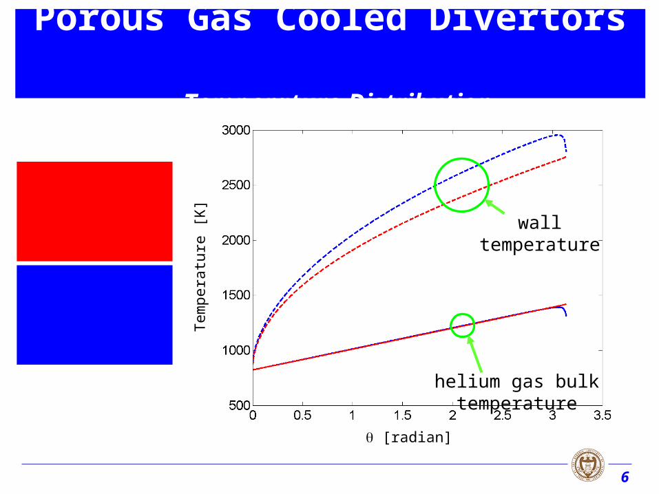
Tin=823K, Tout=1423K
Heat input : Q=30 MW/m2,
Porous medium characteristic dimension : dp=0.1 mm,
Porosity : =0.8
Coolant: Helium at 823K & 4.0 MPa
cpg=5191 J/kg K, kg=0.3 W/m K,
g=3.9610-5 kg/m s,
g=2.327 kg/m3 (for incompressible)
Solid Structure :
ks=100W/m K,
s=19300 kg/m3, cps=132 J/kg K
6
Tem
pera
ture
[K
]
[radian]
helium gas bulk temperature
wall temperature
Incompressible
Compressible
Porous Gas Cooled Divertors Temperature Distribution

7
Pre
ssur
e dr
op [
MP
a]
Velocity [m/s]
Pre
ssur
e dr
op [
MP
a]
Velocity [m/s]
p
og
p
og
d
V
d
V
ds
dP2
323
2 )1(75.1
)1(150
Ergun equation
Pressure drop P =
0rd
ds
dP
Tin=823K, Q=5 MW/m2, dp=0.1 mm
Porosity : =0.5 Porosity : =0.8
Porous Gas Cooled Divertors Pressure Drop
8
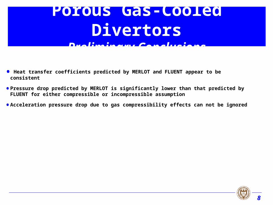
Porous Gas-Cooled DivertorsPreliminary Conclusions
• Heat transfer coefficients predicted by MERLOT and FLUENT appear to be consistent
• Pressure drop predicted by MERLOT is significantly lower than that predicted by FLUENT for either compressible or incompressible assumption
• Acceleration pressure drop due to gas compressibility effects can not be ignored

9
• This work is aimed at establishing limits for the maximum allowable temperature gradients (i.e. heat flux gradients) to prevent film rupture due to thermocapillary effects
Thin-Liquid-Protected DivertorsObjective
A maximum allowable surface temperature has been established to limit liquid evaporation and plasma contamination (~380 oC for Li)

10
)
2-(
2cos)( l
lsms
xx
xTTxT
Thin-Liquid-Protected Divertors Problem Definition
Non-uniform wall temperature
Wall
Thin Film
ho initial film thickness
xl
yl
• Initially, quiescent liquid and gas (u=0, v=0, T=Tm at t=0)
Liquid (Lithium)
Gas (Air)periodic B.C. in x direction
open B.C. at top, 0
y
T
y
v
y
u
x
y

11
• Evolution of the free surface is modeled using the Level Contour Reconstruction Method
• Two Grid Structures Volume - entire computational domain
(both phases) discretized by a standard, uniform, stationary, finite difference grid.
Phase Interface - discretized by Lagrangian points or elements whose motions are explicitly tracked.
Phase 2
Phase 1
F
Thin-Liquid-Protected Divertors Numerical Method

12
A single field formulation
Constant but unequal material properties
Surface tension included as local surface delta function sources
0 u
)(
T )dδ()(t
f sσκμρPt
ρ xxnuuguuu
TkcTt
cTρ
)()(
u• Energy
• Momentum
• Conservation of Mass
Thin-Liquid-Protected Divertors Governing Equations

13
)(d)(
d AABB
B
As
e ss
sF ttt
n
Force on a line element
NUMERICAL METHOD
tnttt
ssss
)(
thermocapillary force
normal surface tension force
o=6.6210-2 N/m
o=1.7410-4 N/moC
Tm=573 K
)( moo TT
Thin-Liquid-Protected Divertors Variable Surface Tension Source Term
Variable surface tension :
BtBAtA
n
n : unit vector in normal direction
t : unit vecotr in tangential direction
: curvature

14
),()(),( tIt GLG xx
),()(),( tIt GLG xx
• Material property field (Liquid=>Lithium, Gas=>Air*)
),()(),( tIccctcc GLG xx
),()(),( tIkkktkk GLG xx
(L=504.8 kg/m3, G=1.046 kg/m3)
(L=4.5110-4 kg/ms, G=2.010-5 kg/ms)
(cL=4287 J/kgoC, cG=1008 J/kgoC)
(kL=46.6 W/moC, kG=0.029 W/moC)
Thin-Liquid-Protected Divertors Material Properties
* Effect of Liquid/Gas density ratio becomes insignificant for values 100

15
• Two-dimensional simulation with 0.01[m]0.001[m] box size and 25050 resolution
• ho=0.2 mm, Ts=10 K
Thin-Liquid-Protected Divertors Steady State Results, very thin films
x [m]
y [m
]
time [sec]
y [m
]

16
• Two-dimensional simulation with 0.01[m]0.001[m] box size and 25050 resolution
• ho=0.2 mm, Ts=10 K
Thin-Liquid-Protected Divertors Steady State Results, very thin films
velocity vector plot
temperature plot

17
• Two-dimensional simulation with 0.01[m]0.001[m] box size, 25050 resolution, and ho=0.2 mm
Thin-Liquid-Protected Divertors Steady State Results, very thin films
x [m]
y [m
]
time [sec]
y [m
]
black : Ts=10 K blue : Ts=20 K red : Ts=30 K
maximum y location
minimum y location

18
Thin-Liquid-Protected Divertors Steady State Results, moderate film thickness
x [m]
y [m
]
• Two-dimensional simulation with 0.1[m]0.01[m] box size and 25050 resolution
• ho=2 mm, Ts=100 K

19
• Two-dimensional simulation with 0.1[m]0.01[m] box size and 25050 resolution
• ho=2 mm, Ts=100 K
Thin-Liquid-Protected Divertors Steady State Results, moderate film thickness
velocity vector plot
temperature plot

20
• Two-dimensional simulation with 0.1[m]0.01[m] box size, 25050 resolution, and ho=2 mm
Thin-Liquid-Protected Divertors Steady State Results, moderate film thickness
y [m
]
time [sec]
maximum y location
minimum y location
black : Ts=100 K blue : Ts=250 K

21
Thin Liquid-Protected DivertorsPreliminary Conclusions
• Methodology can be used to determine the Limiting values for temperature gradients (i.e. heat flux gradients) necessary to prevent film rupture
• In some cases (very thin films), limits may be more restrictive than surface temperature limits
• Path Forward:
Generalized charts will be developed to determine the temperature gradient limits for different fluids and film thickness values


![Wahyu khalik safety and security tourism.pptx [autosaved]](https://img.dokumen.tips/doc/110x75/55c63493bb61eb90668b4622/wahyu-khalik-safety-and-security-tourismpptx-autosaved.jpg)


