Embed Size (px)
DESCRIPTION
Preiss Core Standards in the Pressure Equipment Area 4668
Citation preview
1
Core Standards in the Pressure Equipment Area
Core Standards in the Pressure Equipment Area
Workshop on the Pressure Equipment DirectiveRiga, November 27&28, 2003
Dr. Reinhard PreissTÜV AustriaKrugerstrasse 16
A-1015 Vienna, AustriaTel. +43 1 51407 6136e-mail: [email protected]
http://www.tuev.at
Ref. Ares(2014)75244 - 15/01/2014

2
Harmonized Standards1) in the Pressure Equipment Area
Harmonized Standards1) in the Pressure Equipment Area
EN 13445 - Unfired Pressure Vessels
EN 13480 - Metallic Industrial Piping
EN 12952 - Water Tube Boilers and Auxiliary Installations
EN 12953 – Shell Boilers
1) Pressure equipment and assemblies which conform to the national standards transposing the harmonized standards the reference numbers of which have been published in the Official Journal of the European Communities shall be presumed to conform to the essential requirements referred to in Article 3 PED.

3
EN 13445 – Unfired Pressure Vessels1)EN 13445 – Unfired Pressure Vessels1)
Part 1 - GeneralPart 2 - MaterialsPart 3 - DesignPart 4 - FabricationPart 5 - Inspection and TestingPart 6 - Requirements for the design and fabrication of pressure vessels and pressure vessel parts constructed from spheroidal graphite cast iron
1) Figures and Tables from EN 13445 shown in this presentation are only intended for clarification of requirements of EN 13445 and do not necessarily correspond to the latest revision of the standard. Usage for other purposes, e.g. for design and manufacturing of pressure vessels, is not permitted. All rights of exploitation reserved worldwide for CEN national members.
4
EN 13445–1 General: ScopeEN 13445–1 General: Scope
EN 13445 applies to unfired pressure vessels subject to internalpressure greater than 0,5 bar(g), but may be used for vessels operating a lower pressures, including vacuum.
EN 13445 applies to maximum allowable temperatures for which creep effects need not be considered, i.e. for maximum allowabletemperatures for which the corresponding maximum calculation temperature renders a relevant proof strength smaller than the 100000 h creep rupture strength (ferritic steels: approx. 380°C, austenitic steels: approx. 425°C)
5
EN 13445–1 General: ScopeEN 13445–1 General: Scope
EN 13445 is not applicable to
Transportable pressure equipment
Items specially designed for nuclear use
Pressure equipment for generation of steam or superheated water at temperatures higher than 110°C
Vessels of riveted construction
Vessels of laminar cast iron or other material not included in Part 2 or Part 6
Multilayered, autofrettaged or pre-stressed vessels
Pipelines and industrial piping
6
EN 13445–2 MaterialsEN 13445–2 MaterialsCurrently limited to steels with sufficient ductility
Minimum elongation after fracture
≥ 14% transverse or critical direction≥ 16% longitudinal or less critical direction
Specified minimum impact energy (Charpy-V), at a test temperature in accordance with Annex B but not higher than 20°C:
≥ 27 J ferritic steels, steels with 1.5 - 5.0 % Ni
≥ 40 J other (35 J for some austenticsteels)Maximum carbon, phosphorus und sulfur contents for steels (e.g. for ferritic steel (not stainless) – max. values for cast analysis: Cmax=0.23%, Pmax=0.035%, Smax=0.025%)
7
EN 13445–2 MaterialsEN 13445–2 Materials
Technical delivery conditions :
European Standardse.g. EN 10028 (plate), EN 10222 (forging), EN 10216 (seamless pipe), EN 10217 (welded pipe), EN 10269 (fasteners)European Approval for Materials
Particular Material Appraisal
Technical delivery conditions for welding consumables shall be in accordance with EN 12074 and prEN 13479-1.

8
EN 13445–2 Materials: Grouping SystemEN 13445–2 Materials: Grouping System
Scan
9
EN 13445–2 Materials: Annex BEN 13445–2 Materials: Annex B
Requirements for prevention of brittle fracture
Method 1: Technical requirements applicable to all metallic materials, but limited to certain thicknesses for which experience exist.
Method 2: Technical requirements only applicable to C, CMn and low alloy ferritic steels with a minimum yield strength 460 N/mm2.
Method 3: Application of fracture mechanics. Only general guidance is given on the use of this method which shall only be used in agreement with the parties concerned.
≤

10
EN 13445–2 Materials: Annex B Method 1EN 13445–2 Materials: Annex B Method 1
Scan Table B1

11
EN 13445–2 Materials: Annex B Method 2EN 13445–2 Materials: Annex B Method 2Partent Material, welds and HAZ shall be meet the energy KV at impact
test temperature TKV. Table B.5 shows which figure shall be used to determine the impact test temperature TKV or the design reference temperature TR.

12
EN 13445–2 Materials: Annex B Method 2EN 13445–2 Materials: Annex B Method 2
Scan Figure B2
13
EN 13445–2 Materials: Annex B 4.2EN 13445–2 Materials: Annex B 4.2
Production test plates
Weld production test plate shall be performed in accordance with clause 8 of EN 13445-4.
The following requirements are additional to the requirements to clause 8 of EN 13445-4. In addition to this a weld production test plate1) is required according to welding procedure specification for TKV equal to or above -30°C, if the material thickness is greater than 12mm.
For TKV below -30°C, a weld production test plate1) is required if the material thickness is greater than 6mm.
The impact energy requirements of method 1 or 2 shall be met.
1) on a longitudinal seam per vessel

14
EN 13445–3 Design: Basic CriteriaEN 13445–3 Design: Basic CriteriaThe requirements specified in clauses 7 to 16 (DBF) provide satisfactory design for pressure loading of non-cyclic nature, i.e. when the number of full pressure cycles is less than 500. Then no fatigue analysis is necessary and the standard requirements of non destructive testing given in EN 13445-5 shall be applied.
For ni pressure cycles at a pressure Pi less than the full pressure P, the number of equivalent full pressure cycles is given by:
If a fatigue analysis is required it can be performed according to clause 17 (simplified fatigue analysis, rules only for cyclic pressure, conservative) or clause 18 (detailed fatigue analysis, normally by usage of FEM). NDT requirements according to Annex G of EN 13445-5 shall be used.
3
max⎟⎟⎠
⎞⎜⎜⎝
⎛⋅Σ=
PPnn i
ieq

15
EN 13445–3 Design: Basic CriteriaEN 13445–3 Design: Basic CriteriaWeld joint coefficient z for governing welded joints:
For exceptional and testing conditions, a value of 1 shall be used irrespective of the testing group.
The amount of NDT in accordance with EN 13445-5 depends on the testing group used for the vessel or the part of the vessel.
Pressure vessels to testing group 4 are intended to non-cyclic operations and are limited to 500 full pressure cycles or equivalent pressure cycles.
For testing group 4, the maximum nominal design stress for normal operating load cases shall be multiplied by 0,9.
431, 2Testing group
0,70,851z
16
EN 13445–3 Design: Basic CriteriaEN 13445–3 Design: Basic Criteria
Governing welded joints are
Longitudinal or helical welds in cylindrical shells
Longitudinal welds in a conical shell
Any main weld in spherical shell/head and main welds in a dishedhead
Not governing welded joints are
Circumferential welds between a cylindrical or conical shell and a cylinder, cone, flange or end other than hemispherical
Welds attaching nozzles to shells
Welds subjected exclusively to compressive stress

17
EN 13445–3 Design: Allowable stressEN 13445–3 Design: Allowable stress
Maximum allowable nominal design stresses:
Normal operating load cases Testing and exceptional l..c.
Steels other than austentic
⎥⎦
⎤⎢⎣
⎡=
4.2R;
5.1R
Minf 20/mT/2.0p 05.1/2.0 Ttestp
test
Rf =
Austenitic steels 35 > A ≥ 30% 5.1
Rf T/0.1p= 05.1
/0.1 Ttestptest
Rf =
Austentitc steels A ≥ 35% ⎥
⎦
⎤⎢⎣
⎡⎥⎦
⎤⎢⎣
⎡=
0.3;
2.1;
5.1//0.1/0.1 TmTpTp RR
MinR
Maxf ⎥⎦
⎤⎢⎣
⎡=
0.2R;
05.1R
Maxf Ttest/mTtest/0.1ptest
Cast steels ⎥⎦
⎤⎢⎣
⎡=
0.3R;
9.1R
Minf 20/mT/2.0p 33.1
Rf Ttest/2.0p
test =
The yield strength ReH may be used in lieu of Rp0.2 if the latter is not available

18
EN 13445–3 Design: DBFEN 13445–3 Design: DBF
Clause 7: DBF for shells under internal pressure - iterative or direct calculation of the required wall thicknessesCylindrical and spherical shellsDished endsCones and conical endsNozzles in the knuckle region
Clause 8: DBF for shells under external pressure - iterative or direct calculation of the required wall thicknesses and stiffenersCylindrical shellsConical shellsSpherical shellsVessel ends

19
EN 13445–3 Design: DBFEN 13445–3 Design: DBFClause 9: Openings in shells
Clause 10: Flat ends
Clause 11: FlangesFlanges that conform to an EN standard for pipework flanges (e.g. EN 1092-1) with pressure-temperature ratings may be used as pressure vessel components without any calculation under particular conditions. Flange calculation in clause 11 is based on Taylor-Forge methodAlternative rules for narrow face gasket flange design in Annex G are most appropriate when: a) thermal cycling is important, b) bolt stress is controlled by use of a tightening procedure, c) there are significant additional loadings (forces or moments) or d) leak tightness is of special importance.

20
EN 13445–3 Design: DBFEN 13445–3 Design: DBFClause 12: Bolted domed ends (Alternative Rules according to Annex G)
Clause 13: Heat exchanger tubesheets (Alternative Rules according to Annex J)
Clause 14: Expansion bellows
Clause 15: Pressure vessels of rectangular section
Clause 16: Additional non-pressure loadsLocal loads on nozzles in spherical or cylindrical shellsLine loadsLifting lugsHorizontal vessels on saddle supports, or on ring supportsVertical vessels on bracket supports, with supporting legs, with skirts, with ring support Global loads

21
EN 13445–3 Design: FatigueEN 13445–3 Design: FatigueClause 17: Simplified assessment of fatigue life
Simplified assessment of fatigue damage due to pressure fluctuations
P shall be obtained by applying the simplified cycle counting method or the reservoir cycle counting method and considering fluctuations of pressure instead of stress (details on the methods are given in clause 18).
The stress range is calculate by usage of a value which is given in Table 17-1, and is defined as ratio of the maximum structural stress to the nominal design stress.
The total fatigue damage is calculated to
Δ
σΔ η
∑ ≤=++=k
j
j
Nn
Nn
NnD
12
2
1
1 1.....

22
EN 13445–3 Design: FatigueEN 13445–3 Design: Fatigue
Clause 17: Fatigue design curves
23
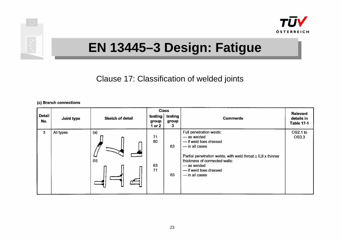
EN 13445–3 Design: FatigueEN 13445–3 Design: Fatigue
Clause 17: Classification of welded joints

24
EN 13445–3 Design: FatigueEN 13445–3 Design: FatigueClause 18: Detailed assessment of fatigue life
Detailed assessment of fatigue damage due to fluctuations of allloads (pressure, thermal, mechanical loads, etc..), determination of the stresses usually by FEM, linear damage accumulation model asin clause 17.
shall be obtained by applying the simplified cycle counting method or the reservoir cycle counting method .Total stresses to be used for unwelded regions, allowable cycle number for a given stress range calculated iteratively.Structural stresses to be used for welded regions, allowable cycle number for a given stress range calculated directly.Classification of welded jointsStructural equivalent stress range or structural principal stress range can be used for welded regions, the latter may result in a higher number of cycles.
σΔ
25
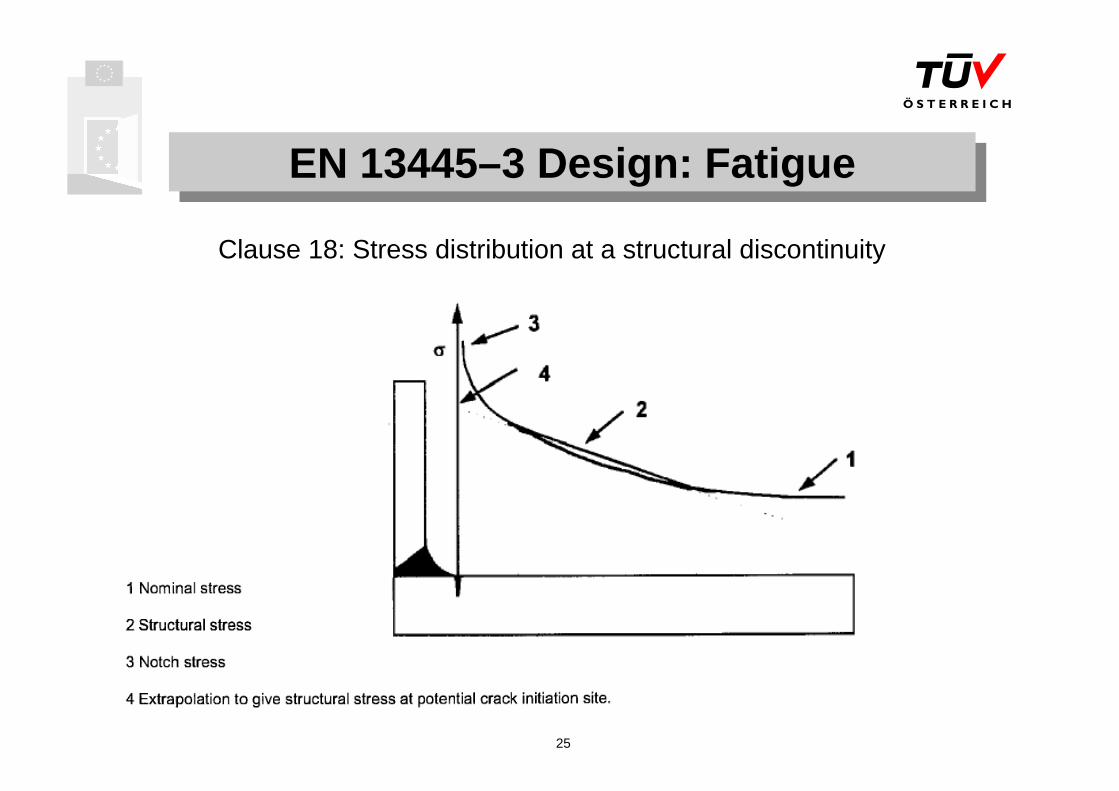
EN 13445–3 Design: FatigueEN 13445–3 Design: Fatigue
Clause 18: Stress distribution at a structural discontinuity

26
EN 13445–3 Design: DBAEN 13445–3 Design: DBAAnnex B (normative) DBA – direct route
As a complement and as an alternative to DBFFlexibility due to the partial safety factor concept (for actions and for resistances)Avoids uncertainties in stress categorisation due to direct addressing of the relevant failure modes (e.g. via elastic-plastic FEA)Failure modes considered are: a)Gross plastic deformation, b)Progressive deformation, c)Fatigue, d)Instability, e)Static equilibrium.New, innovative method for DBA, some principals might be adaptedby other codes (e.g. ASME VIII Div.2)Further information (DBA manual): see http://ped.eurodyn.com via links JRC and DBA
Annex C (normative) DBA – method based on stress categories
27
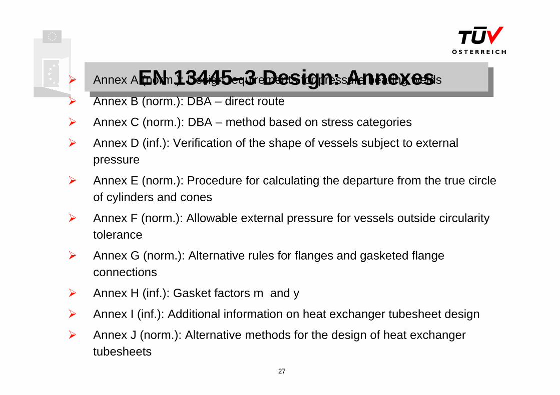
EN 13445–3 Design: AnnexesEN 13445–3 Design: AnnexesAnnex A (norm.): Design requirements for pressure bearing welds
Annex B (norm.): DBA – direct route
Annex C (norm.): DBA – method based on stress categories
Annex D (inf.): Verification of the shape of vessels subject to external pressure
Annex E (norm.): Procedure for calculating the departure from the true circle of cylinders and cones
Annex F (norm.): Allowable external pressure for vessels outside circularity tolerance
Annex G (norm.): Alternative rules for flanges and gasketed flange connections
Annex H (inf.): Gasket factors m and y
Annex I (inf.): Additional information on heat exchanger tubesheet design
Annex J (norm.): Alternative methods for the design of heat exchanger tubesheets

28
EN 13445–3 Design: AnnexesEN 13445–3 Design: Annexes
Annex K (inf.): Additional information on expansion bellows design
Annex L (inf.): Basis for design rules related to non-pressure loads
Annex M (inf.): Measures to be adopted in service
Annex N (inf.): Bibliography to clause 18
Annex O (inf.): Physical properties of steel
Annex P (norm.): Classification of weld details to be assessed using principal stresses
Annex Q (norm.): Simplifies procedure for fatigue assessment of unwelded zones
Annex ZA (inf.): Clauses of this European Standard addressing essential requirements or other provisions of the EU directives

29
EN 13445–4 FabricationEN 13445–4 Fabrication
ScopeMaterials traceabilityManufacturing tolerancesWelding requirementsProduction testsForming requirementsHeat treatmentRepairs and finishing operations

30
EN 13445–4 Fabrication: WeldingEN 13445–4 Fabrication: WeldingWelding procedure specifications (WPS) shall be in accordance with EN 288-2.Welding procedure approval test for pressure retaining welds shall be performed in accordance with EN 288-3 or by pre-production tests in accordance with EN 288-8 (additional requirements are given in clause 7.3 of EN 13445-4).Welding procedure approval test for other than pressure retaining welds directly attached to the pressure vessel may be acceptable by holding welding procedure approval records carried out in accordance with EN 288-6 and EN 288-7.Welders and welding operators shall be approved to EN 287-1 or EN 1418 resp.The manufacturer shall include the preheating temperatures in the WPS.

31
EN 13445–4 Fabrication: Production testEN 13445–4 Fabrication: Production testProduction test plates apply only to governing weldsFor vessels in testing group 4 no production test plates are requiredExample of requirements: production test plate are required for material group 1.1, 1.2 and 8.1:
Longitudinal weld, one test plate per vessel if z = 1.0One test plate per 100m of longitudinal weld if z = 0.85
After 10 consecutive test plates have successfully pasted the test,
One test plate per 100m of longitudinal weld if z = 1.0One test plate per 1000m of longitudinal weld if z = 0.85
The required testing of production test plates are dependent on the material and the thickness.

32
EN 13445–4 Fabrication: FormingEN 13445–4 Fabrication: FormingTemperature requirements for cold forming and hot forming for the different materialsRequirements for heat treatment after cold and hot forming for the different materialsNo mechanical tests are required for cold formed products without heat treatment.Requirements for hot formed or cold formed products with heat treatment: Formed products shall be individually tested until the manufacturer has passed 30 test coupons within the appropriate material group. Thereafter the tests are performed per batch ( a batch is defined by products of the same cast and the same final heat treatment).
33
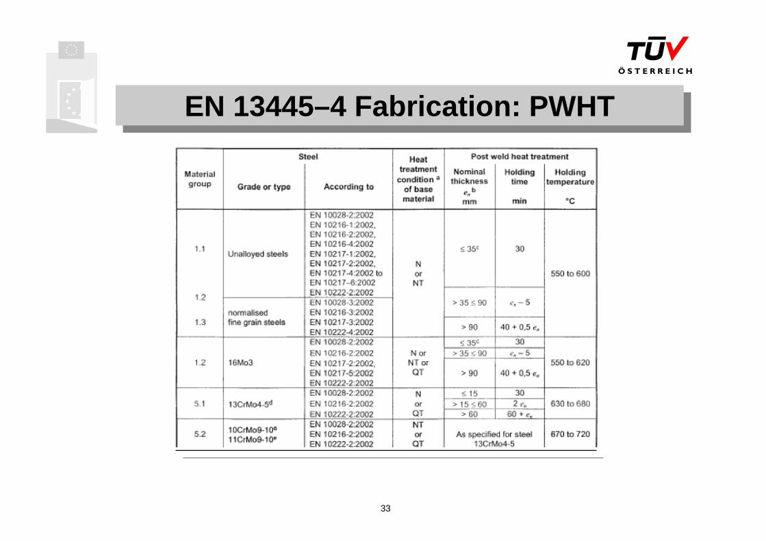
EN 13445–4 Fabrication: PWHTEN 13445–4 Fabrication: PWHT

34
EN 13445–4 Fabrication: PWHTEN 13445–4 Fabrication: PWHT
Mechanical properties after heat treatment – limits for maximum and holding time without effect on strength of the base material: PWHT time not exceeding 3 h at required PWHT temperature for material in groups 1.1 and 1.2 (except 16Mo3)PWHT temperature at least 30°C below the maximum tempering temperature and PWHT time not exceeding 3 h for all other materials.
If the conditions above are not fulfilled, test coupons heat treated with the vessel or subjected to a simulated PWHT are required (Note: possible exception for material in groups 1.1 and 1.2 - except 16Mo3 -, depending on the actual yield and tensile strength as per the relevant material test certification).

35
EN 13445–5 Inspection and TestingEN 13445–5 Inspection and Testing
Specification of the inspection and testing of individual or serially produced pressure vessels made of steels in accordance with EN 13445-2 predominantly subject to non-cyclic operation.
Special provisions for cyclic operation are given in Annex G of this part and in EN 13445-3.Material traceability: The manufacturer shall have an identification system, so that all material subject to stress due to pressure and those welded thereto in the completed vessel can be traced to its origin.

36
EN 13445–5 Inspection and Testing: NDTEN 13445–5 Inspection and Testing: NDTNDT of welded joints for final acceptance purposes shall depend upon the testing group of the welded joints under consideration (i.e. testing group 1, 2, 3 and 4).
Testing groups 1, 2 and 3 are subdivided into sub-groups 1a, 1b, 2a, 2b, 3a, 3b, in order to reflect the crack sensitivity of the material.
Where combinations of testing groups 1, 2 and 3 occur, the following shall occur:
In each section (course), the testing group of the governing welded joints shall determine the minimum group for all the weld in that section (including nozzle welds)The testing group of the weld between two welded sections shall be the higher oneThe minimum testing group between a welded and a seamless component, or between two seamless components, shall be determined by the available thickness at the weld. If it is greater than 1,17 (=1/0,85) times the minimum thickness, the testing group of the weld shall be 3 as a minimum requirement. Otherwise it shall be testing group 1 or 2.

37
EN 13445–5 Inspection and Testing: NDTEN 13445–5 Inspection and Testing: NDTTesting group 4 shall be used as a single testing group for the entire vessel.
Testing group 4 shall be applicable only for: Group 2 fluids
PS not greater than 20 bar
PS.V not greater than 20000 bar.L above 100°C, or PS.V not greater than 50000 bar.L equal or less 100°C
higher pressure test
maximum number of full pressure cycles less than 500
lower level of nominal design stress.
NDT testing personal shall be qualified and certified in accordance with EN473.

38
EN 13445–5 Inspection and Testing: NDTEN 13445–5 Inspection and Testing: NDT
Scan Table 6.6.1-1

39
EN 13445–5 Inspection and Testing: NDTEN 13445–5 Inspection and Testing: NDT

40
EN 13445–5 Standard hydrostatic testEN 13445–5 Standard hydrostatic testFor a vessel according to testing group 1, 2 and 3 the test pressure shall not be less than that determined by the following: or ,
whichever is the greater, wherePt is the test pressure
PS is the maximum allowable working pressure
fa is the nominal design stress for design conditions at test temperature
ft is the nominal design stress for design conditions at the max. allow. temperature
The ratio (fa/ft) to be used shall be the greatest ratio of those permitted based on the material for the main pressure envelope elements.
In all cases for each component of the vessel the test pressure shall be limited such that it does not generate a design stress greater than that given in EN 13445-3 for testing conditions, by reducing the test pressure, if necessary.
t
at f
fPSP ⋅⋅= 25.1 PSPt ⋅= 43.1

41
EN 13445–5 Insp. and Testing: AnnexesEN 13445–5 Insp. and Testing: AnnexesAnnex A (norm.): Inspection and testing of serially produced vessels (Note: limitations given in A.2)Annex B (norm.): Detailed dimensional requirements for pressure vesselsAnnex C (norm.): Access and inspection openings, closing mechanisms and special locking elementsAnnex D (inf.): Leak testingAnnex E (inf.): Acoustic emissionAnnex F (norm.): Standard hydrostatic test in case of static head acting in service or testingAnnex G (norm.): Inspection and testing of pressure vessels subjected to cyclic loadsAnnex H (inf.): Declaration of compliance with this standardAnnex ZA (inf.): Clauses of this European Standard addressing essential requirements or other provisions of the EU directives

42
Comparative Study on Pressure Equipment Standards
Comparative Study on Pressure Equipment Standards
A consortium of European partners, leaded by TUV Austria, is currently performing a "Comparative Study on Pressure Equipment Standards" on behalf of the European Commission. The study will compare the economic and non-economic implications in the application of (a) the EN 13445 (European Harmonized Standard for Unfired Pressure Vessels) and, (b) the internationally used ASME Boiler & Pressure Vessel Code plus major related codes when appropriate (TEMA, WRC bulletin), for the design, manufacture, inspection and acceptance testing of a 9 benchmark example unfired pressure vessels.
Results will be available in spring 2004.

![Aromataseinhibitorsfortreatmentofadvancedbreastcancer ...researchonline.lshtm.ac.uk/4668/1/Gibson_et_al... · [Intervention Review] Aromatase inhibitors for treatment of advanced](https://img.dokumen.tips/doc/110x75/606bd20ad618f10fde1d84e4/aromataseinhibitorsfortreatmentofadvancedbreastcancer-intervention-review.jpg)