Embed Size (px)
DESCRIPTION
Livro de pre-fabricação
Citation preview

Eline den Hartog December 2008
Prefabrication of concrete shells


Prefabrication of concrete shells
Eline den Hartog December 2008
Master’s thesis committee:
Prof. ir. L.A.G. WagemansIr. J.L. CoendersIr. A. BorgartDr. ing. S. Grunewald
Delft University of TechnologyFaculty of Civil Engineering and GeosciencesBuilding EngineeringStructural Design Lab

Prefabricated concrete shells

Preface
i
Preface
This report is the product of my Master’s thesis of the Master Building Engineering at the faculty of Civil Engineer-ing of Delft University of Technology. This Master’s thesis is performed at the Structural Design Lab. The Structural Design Lab is an educational and research body which deals with subjects of innovative structures, the relating (struc-tural) design process and related technologies.
This Master’s thesis is about the prefabrication of concrete shells. This report shows the results of the research to the different aspects of the design process of prefabricated concrete shells. On the basis of this research an overview of the design process of these types of shell is made. The process of segmentation and element generation of the shell and a case study in which the process is evaluated are presented.
I would like to thank my graduation committee, Prof. ir. L.A.G. Wagemans, Ir. J.L. Coenders, Ir. A. Borgart and Dr. ing. S. Grunewald for their guidance and ideas during the project. Furthermore, I would like to thank the other gradu-ates in room 0.72 for their company during the coffee and lunch breaks. Last but not least I would like to thank my boyfriend and my family for supporting me during my study and my graduation in particular.
Eline den HartogDelft, December 2008

ii
Prefabrication of concrete shells

Summary
iii
count during the structural analysis, because they influ-ence the structural behaviour of the shell.
Grid generation
The grid generation method will be used to generate a grid over a free form surface that forms the basis of the division of the surface into elements. There are different types of grid generation techniques that can be divided in struc-tured grids, unstructured grids and composite grids. From a theoretical point there is no optimal grid generation technique that results in the best grid for every surface. The most suitable grid generation technique for a surface depends on the geometry of the surface, the architectural design and the structural layout.
Concrete composites
The high performance fibre reinforced concrete compos-ites form a good solution for the use in prefabricated con-crete shell structures, they might make it possible that no ordinary reinforcement is used in the elements. There are many different types of high performance fibre reinforced concrete composites developed, that all have their own characteristics and are suitable for different applications. The most recently developed concrete composites, with different types of fibres added to it, have the best proper-ties for the application in prefabricated shell structures.
Formwork
The adjustable formwork is still in the experimental phase of its development and cannot be used jet for the produc-tion of elements for a real structure. The research does show that in the near future is should be possible to use the adjustable formwork.The mould should be easy and fast adjustable in order to produce the different elements of the structure. The maxi-mum size of the elements that have to produced with the flexible formwork is 3,0 x 3,0 m. The minimal radius of
SummaryIntroduction The Fifties and Sixties of the previous century were the golden era of thin concrete shell roofs. Two characteristics that made these thin shells very popular are the strength, and the architectural exciting forms. After this golden era the construction of these thin concrete shells has stag-nated. Reasons for this stagnation could be found in the difficulties that had to be encountered in the realization of these structures. One of the attempts to make the con-struction of shell more often build is with the prefabrica-tion of the shell.
Problem definitionNot many free formed shell structures in prefabricated concrete have been build. One of the reasons for this is that the design and production process of free formed shells in prefabricated concrete is not efficient enough to make the construction of these shells feasible in most cases.
ResearchDuring this Master’s thesis it is tries to find the difficulties and possibilities of the different aspects of the design and production process of prefabricated concrete shells and to come with possible solutions to overcome these difficul-ties to make the construction of prefabricated concrete shells more feasible.
Design aspects
Structural analysis
The structural analysis of shell structures is made a lot eas-ier with the introduction of finite element analysis soft-ware. However, for the use of these numerical programs some basic knowledge of the underlying theories and the mechanical behaviour of the structure are still essential.With prefabricated concrete shells the strength, stiffness and location of the connections have to be taken into ac-
The aircraft museum in Duxford is one of the few prefabricated concrete shell structures.
Model of the adjustable formwork as it is in development at the moment.
iv
Prefabrication of concrete shells
to achieve a maximal optimization of the design with the minimum amount of effort. The automation of some parts of the design process can ease the design of complicated structures, but thorough control of the found solutions will always be necessary. For optimization in the building industry there is most of the time not one solution that is the most optimal in all cases, this makes it more difficult to automate the optimization processes.
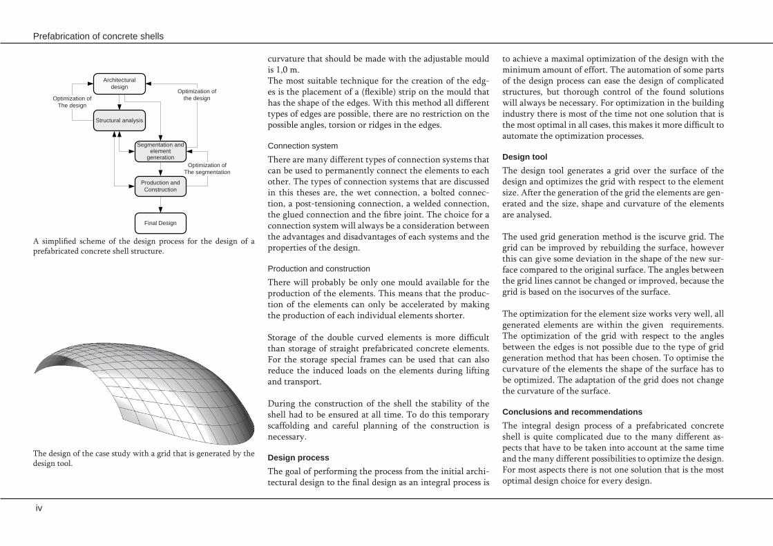
Design toolThe design tool generates a grid over the surface of the design and optimizes the grid with respect to the element size. After the generation of the grid the elements are gen-erated and the size, shape and curvature of the elements are analysed.
The used grid generation method is the iscurve grid. The grid can be improved by rebuilding the surface, however this can give some deviation in the shape of the new sur-face compared to the original surface. The angles between the grid lines cannot be changed or improved, because the grid is based on the isocurves of the surface.
The optimization for the element size works very well, all generated elements are within the given requirements. The optimization of the grid with respect to the angles between the edges is not possible due to the type of grid generation method that has been chosen. To optimise the curvature of the elements the shape of the surface has to be optimized. The adaptation of the grid does not change the curvature of the surface.
Conclusions and recommendationsThe integral design process of a prefabricated concrete shell is quite complicated due to the many different as-pects that have to be taken into account at the same time and the many different possibilities to optimize the design. For most aspects there is not one solution that is the most optimal design choice for every design.
curvature that should be made with the adjustable mould is 1,0 m. The most suitable technique for the creation of the edg-es is the placement of a (flexible) strip on the mould that has the shape of the edges. With this method all different types of edges are possible, there are no restriction on the possible angles, torsion or ridges in the edges.
Connection system
There are many different types of connection systems that can be used to permanently connect the elements to each other. The types of connection systems that are discussed in this theses are, the wet connection, a bolted connec-tion, a post-tensioning connection, a welded connection, the glued connection and the fibre joint. The choice for a connection system will always be a consideration between the advantages and disadvantages of each systems and the properties of the design.
Production and construction
There will probably be only one mould available for the production of the elements. This means that the produc-tion of the elements can only be accelerated by making the production of each individual elements shorter.
Storage of the double curved elements is more difficult than storage of straight prefabricated concrete elements. For the storage special frames can be used that can also reduce the induced loads on the elements during lifting and transport.
During the construction of the shell the stability of the shell had to be ensured at all time. To do this temporary scaffolding and careful planning of the construction is necessary.
Design processThe goal of performing the process from the initial archi-tectural design to the final design as an integral process is
The design of the case study with a grid that is generated by the design tool.
Architectural design
Structural analysis
Segmentation and element
generation
Production and Construction
Optimization ofThe segmentation
Optimization of the designOptimization of
The design
Final Design
A simplified scheme of the design process for the design of a prefabricated concrete shell structure.

Summary
v
The developed design tool is capable of generating a grid over a lot of different surfaces. However not for every sur-face an optimal grid is generated. A large drawback of the used grid generation technique is that the angle between the grid lines cannot be optimized.
For the production and construction of the shell it is bet-ter when no reinforcement needs to be applied in the ele-ments.
To make a next step in the development of prefabricated concrete shell it is advised to really build a prefabricated shell structure of which the elements are made with the adjustable formwork.
It is recommended to perform further research to the structural behaviour of prefabricated concrete shell struc-tures. For the increase of the application of high perform-ance fibre reinforced concrete composites it is advised that a design code is developed for these type of concrete com-posites.

vi
Prefabrication of concrete shells

Table of contents
vii
Table of contents at a glance
1. Introduction 1
2. Mechanics 17
3. Grid generation 33
4. Concrete Composites 49
5. Adjustable formwork 67
6. Edges and connections 77
7. Production and construction 91
8. Design process 103
9. Geometry design tool 115
10. Case study 133
Conclusions & Recommendations 153
References 159
Appendices 165

viii
Prefabrication of concrete shells
Table of contents
ix
Table of contents
1. Introduction 11.1 Introduction 31.2 Recently build prefabricated concrete ‘shell’ structures 6 1.2.1 American Air museum, Duxford, 1997 6 1.2.2 The Shawnessy LRT station canopies Calgarry, Canada, 2003 8 1.2.3 Canopy at sanatorium Zonnestraal, Hilversum, 2005 10 1.2.4 Toll station for the Millau Bridge, France, 2005 11 1.2.5 Concluding remarks 121.3 Problem description and aim 14 1.3.1 Problem description 14 1.3.2 Aim 141.4 Approach 15
2. Mechanics 172.1 Introduction 192.2 Surface Definition 20 2.2.1 Geometrical defined surfaces 20 2.2.2 Non-geometrical defined surfaces 222.3 Membrane and bending theory 24 2.3.1 Membrane theory 24 2.3.2 Bending theory 252.4 Finite Element Analysis 262.5 Shell buckling 272.6 Prefabricated concrete shell structures 282.7 Structural optimization 292.8 Conclusions 31
3. Grid generation 333.1 Introduction 353.2 Terminology and requirements of the grid 36 3.2.1 Terminology 36 3.2.2 Grid requirements 363.3 Structured grids 38 3.3.1 Boundary-confirming grids 38 3.3.2 Translational grids 39 3.3.3 Isotope technique 393.4 Unstructured grids 40
x
Prefabrication of concrete shells
3.4.1 Octree approach 40 3.4.2 Delaunay approach 41 3.4.3 Advancing-front technique 433.5 Composite grids 45 3.5.1 Block structured grids 45 3.5.2 Overset grid 46 3.5.3 Hybrid grids 463.6 Conclusions 47
4. Concrete Composites 494.1 Introduction 514.2 Steel reinforced concrete 524.3 Self compacting concrete 534.4 (Ultra) high performance concrete 544.5 Fibre reinforced concrete 55 4.5.1 Types of fibres 57 4.5.2 Fibre arrangements 58 4.5.3 Production methods 58 4.5.4 Properties of fibre reinforced concrete 594.6 Types of fibre reinforced concrete 61 4.6.1 ECC 61 4.6.2 Slurry Infiltrated Fibre CONcrete (SIFCON) 61 4.6.3 Slurry Infiltrated Mat CONcrete (SIMCON) 62 4.6.4 BSI/CERACEM 62 4.6.5 Ductal 62 4.6.6 CEMTEC 63 4.6.7 Hybrid fibre concrete 63 4.6.8 Evaluation 644.7 Conclusions 66
5. Adjustable formwork 675.1 Introduction 695.2 Strip mould 705.3 Pin bed mould 715.4 Recent developments 73 5.4.1 Adjustable formwork I 73 5.4.2 Adjustable mould II 745.5 Evaluation 755.6 Conclusions 76

Table of contents
xi
6. Edges and connections 776.1 Introduction 796.2 Edges 80 6.2.1 Angle of the element in cross-section 80 6.2.2 Angle of the element in plane 80 6.2.3 Form of the edges 80 6.2.4 Creation of the edges 826.3 Connections 84 6.3.1 Wet connection 84 6.3.2 Bolted connection 84 6.3.3 Post-tensioning connection 85 6.3.4 Welded connection 85 6.3.5 Glued connection 85 6.3.6 Fibre joints 86 6.3.7 Evaluation 876.4 Conclusions 89
7. Production and construction 917.1 Introduction 937.2 Production 94 7.2.1 Virtual mould 94 7.2.2 Inserts for the edges 94 7.2.3 Preparation of the mould 95 7.2.4 Casting process 95 7.2.5 Demoulding 96 7.2.6 Storage of the elements 96 7.2.7 Evaluation 977.3 Transport 987.4 Construction 997.5 Tolerances 1007.6 Conclusions 101
8. Design process 1038.1 Introduction 1058.2 Design aspects 1068.3 Relations between the aspects 1078.4 The design process 110 8.4.1 Architectural design 110 8.4.2 Structural analysis 110 8.4.3 Segmentation and element generation process 111

xii
Prefabrication of concrete shells
8.4.4 Production and construction process 112 8.4.5 Optimization 1138.5 Conclusions 114
9. Geometry design tool 1159.1 Introduction 1179.2 Grid generation 118 9.2.1 Requirements 118 9.2.2 Approach 119 9.2.3 Grid generation techniques 119 9.2.4 Evaluation 1229.3 Generation of the elements 123 9.3.1 Generation of the edges 123 9.3.2 Division of the surface into elements 123 9.3.3 Creation of the inner surface 123 9.3.4 Creation of the elements 124 9.3.5 Method of slicing the shell 124 9.3.6 Evaluation 1259.4 Element control 126 9.4.1 Requirements 126 9.4.2 Control of the element size 126 9.4.3 Control of the angles between the edges 126 9.4.4 Control of the element curvature 1279.5 Design tool 128 9.5.1 Description 128 9.5.2 Testing and evaluation 1309.6 Conclusions 132
10. Case study 13310.1 Introduction 13510.2 Architectural design 136 10.2.1 Concept 136 10.2.2 Model 13610.3 Structural analysis 137 10.3.1 Load definition 137 10.3.2 Shell properties 139 10.3.3 Analysis 140 10.3.4 Conclusions 14210.4 Detailing 143 10.4.1 Shape of the elements 143

Table of contents
xiii
10.4.2 Connections 143 10.4.3 Foundation 14610.5 Segmentation an geometry definition 147 10.5.1 Element size 147 10.5.2 Angles 147 10.5.3 Curvature 147 10.5.4 Geometry definition 148 10.5.5 Optimization 148 10.5.6 Evaluation 14810.6 Production and construction 149 10.6.1 Production process 149 10.6.2 Storage 149 10.6.3 Transport 150 10.6.4 Construction process 15010.7 Conclusion 151
Conclusions & Recommendations 153
References 159
Appendices 165Appendix 1 Personal data and graduation committee 167Appendix 2 Gaussian curvature 169Appendix 3 The test surfaces 171Appendix 4 Rhino mesh tool 175Appendix 5 Case study 177Appendix 6 Functional and technical roof aspects 181

xiv
Prefabrication of concrete shells

1. IntroductionIn this chapter the background of the subject of this Master’s thesis, prefabrication of concrete shells, will be described. An overview over some recently build prefabricated concrete shell structures has been given. And the problem description, the aim and the approach of this thesis will be outlined.
Turin exposition hall by P.L. Nervi. [12]

2
Prefabrication of concrete shells

Introduction
3
plywood was relatively expensive, especially in Europe, even when the form could be re-used several times. Gen-erally open forms were used, the use of these forms only limits the slope angle of the shell. Casting concrete in a thin layer on the curved shell surface is difficult. When the concrete mix is too dry the concrete cannot be com-pacted properly and has to be finished by hand and when the concrete mix is to fluid the concrete tends to sag and flow. Over the years several attempts have been made to reduce the construction costs and ease the construction of the thin shell.
One of these attempts is the use of an inflated membrane as a formwork. Shotcrete is sprayed on the inside of this form after the placement of the reinforcement. The main problems with this method is that the thickness and shape of the structure are difficult to control during the con-struction process and the tolerances of the construction are large.
1.1 IntroductionThe Fifties and Sixties of the previous century were the golden era of thin concrete shell roofs, many shell struc-tures were build by famous designers like Candela, Torroja and Isler. Two characteristics that made these thin shells very popular are the strength, which allows them to cov-er very large areas, and the architectural exciting forms, which often made them seem to defy the laws of gravity. After this golden era the construction of these thin con-crete shells has stagnated. Reasons for this stagnation could be found in the difficulties that have to be encountered in the realization of these structures. These difficulties are the technical difficulties of designing and constructing the shell and the high building costs of the shell.
Traditionally concrete shells were build using a plywood lining attached to a supporting formwork. Scaffolding was used to support the formwork. The plywood is used to ob-tain the required completely smooth surface. The use of
Figure 1.1 Algeciras markethall by Torroja (1934). [64]
Figure 1.3 Xochimiloco restaurant by Candela (1958). [64] Figure 1.4 Deitingen service station by Isler (1968). [64]Figure 1.2 Construction of the formwork for a concrete shell structure.

4
Prefabrication of concrete shells
Figure 1.5 Prefabricated pans of the Turin Exposition hall in place, Nervi. [19]
Segmentation
Another problem that rises is the division of the shell into elements. This division has its influence on the connec-tions, the mould and the building method. The question is whether there is an ideal method that can handle all restrictions of these aspects and make an optimal division of the surface possible.
Concrete composites
The development of new fibre reinforced high strength concrete composites may give new opportunities for thin concrete shells. The fibres probably cannot replace all the ordinary reinforcement, but they can at least reduce the amount of reinforcement that is needed. This would make the reinforcement of the elements easier.
Formwork
If prefabricated panels are used to make a shell structure at this moment a standard fixed formwork is used. The main problem with this type of formwork is that so for each different element a new form has to be made and re-use of the form is almost impossible. A re-usable adjustable formwork may solve this problem. The adjustable mould can be based on the principle of individual in height ad-justable pins covered by a rubber mat.
Connections
It is difficult to find an optimal connection system that can be used for every prefabricated shell structure. The requirements for the connections differ for each indi-vidual shell structure. For the placement of the elements some room for adjustment is needed, but a the same time a strong and stiff connection is required to ensure the sta-bility of the shell.
Other attempts make use of a permanent formwork, like ferro-cement or steel plates. On these permanent forms reinforcement is placed and the additional concrete is cast. Nervi designed and constructed many structures with this technique. The main disadvantages of this system are the high costs and that re-use of the formwork is not possi-ble.
Another way to create concrete shell structures is with the use of prefabricated concrete elements. In this case the shell is divided into elements, which are prefabricated. Af-ter production the elements are placed and connected on the building site. Benefits of this type of construction are the higher concrete quality that can be used, the higher building speed and the better logistic organization com-pared to in-situ cast concrete structures. A drawback of prefabricated concrete shell structures is that the form-work is still very expensive and re-use of the form is only occasionally possible. Other difficulties that rise with this type of shell structures are the construction of the shell and the connections between the elements.
Not many prefabricated concrete shells have been build in the past. But, there are some recent developments that might make prefabricated concrete shell structures more profitable. The prefabricated concrete shells and the de-velopment of these new techniques are the subject of this Master’s thesis.
Mechanics
The structural analysis of thin shells is quite complex due to the three dimensional shape of the shell and the com-bination of in-plane and bending stresses in the shell. The introduction of finite element methods made the analysis of shells easier, but the exact influence of the joint on the force transfer is not known.

Introduction
5
Construction
The construction of the shell also causes some difficulties. Shell structures are strong and stable when they are fin-ished, but during construction they are not capable of sup-porting themselves. The stability of the shell during con-struction has to be ensured with for example scaffolding. To minimize the amount of scaffolding and ease the as-sembly of the elements a good building plan is required.
The above described aspects and difficulties of the prefab-rication of concrete shell structures are discussed in this thesis. Figure 1.6 shows a diagram with these aspects and the choices that already have been made to limit the re-search area of this thesis. This thesis forms a continuation on the Master’s thesis performed by M. van Roosbroeck. [19] The results of this thesis will be used as a starting point for this thesis.
In-situ concrete
Tradititional formwork
Milled formwork
Fabric formworkFomwork
Steel reinfoced concrete
Concrete composite
Segmentation
Mechanics
Construction
Connections
Fibre reinforced concrete
Flexible formwork
Traditional formwork
Inflated membrane formwork
Permanentformwork
Prefabricated concrete
Concrete shell structures
Figure 1.6 Schedule with the different aspects discussed in this Master’s Thesis.

6
Prefabrication of concrete shells
Figure 1.9 Detail of the roof shell [28]
strip around the base of the vault provide enough daylight in the museum, despite the fact that the structure is partly sunken into the ground. The roof was designed in such way that it can support the suspended aircraft.
Mechanical behaviour
The prefabricated concrete roof, works as a shells struc-ture, and spans about 90 meter. The shell is supported by the upper precast concrete ring beam (see Figure 1.9), with a cross section of 1500 x 1000 mm. The upper ring beam is supported by columns made of welded rectangu-lar hollow sections (RHS), who were placed on the lower ring beam. The cross section of the columns is 700 x 300 mm and they have a thickness of 30 mm. The lower ring
1.2 Recently build prefabricated concrete ‘shell’ structures
Figure 1.8 Curved T-shape precast concrete element with cover slap (not on scale) [28]
Figure 1.7 Aircraft museum in Duxford. [64]
This paragraph gives an overview of prefabricated con-crete ‘shell’ structures that are build in the last ten years. Every design will be described and whenever possible the mechanical behaviour, the segmentation, the concrete composition, the connections, the used formwork and the construction method will be discussed.
1.2.1 American Air museum, Duxford, 1997The aircraft museum was designed by Foster and Partners. The design consists of a single vaulted enclosure, with a glazed wall on the south overlooking the museum run-way. The glazing is removable and its support construc-tion can pivot to allow exhibits to be moved in and out of the museum. The glazed wall and the continuous glass

Introduction
7
Connections
The connections have been designed as stiff in-situ con-nections. The seam between the elements is filled with stitching reinforcement and in-situ concrete, a so called wet connection. The stitching reinforcement consists of rods and stirrups.
Formwork
There was no detailed information found about the form-work that was used to cast the elements. But because al-most all the elements are identical it is assumed that only one mould was needed. For the edge elements that differ slightly from the other elements the existing mould could have been adjusted.
Construction
The plinth slab and the floor have been made out of rein-forced in-situ concrete. The other parts of the construc-tion have been made out of precast concrete and have been connected together with wet connections. The pre-cast elements have been placed on temporary scaffolding before the connection is made. After the connections had been made and the concrete has hardened the scaffolding could be removed.
Figure 1.11 Geometry of the roof shell. [28]
beam has a cross section of 1000 x 600 mm. The lower ring beam is supported by a plinth construction and concrete raking columns of different sizes. The plinth construction consists of a green roof on a 250 mm in-situ concrete slab. It forms a tension ring which bears both horizontal and vertical forces from the roof shell.
Segmentation
The shape of the structure is a segment of a torus or do-nut shape (see Figure 1.11). It is a self-supporting concrete structure made out of prefabricated concrete elements. The shape is segmented by rotating a circle along the torus, creating curved elements. In this way a structured grid is created and most elements have the same shape and curvature. Only the elements on the edge of the structure have a different shape.
Concrete composition
The elements have been made out of precast reinforced concrete. They have been designed as a T-shape with a cover slap to create a smooth outer surface (see Figure 1.8). The flange of the elements is 100 mm thick and the cover slab is also 100 mm thick.
Figure 1.10 The shell during construction. [28]
Figure 1.12 Placement of the elements on the temporary scaffolding [28]

8
Prefabrication of concrete shells
Figure 1.14 The different parts of a canopy before connection. [26]
reinforced rib, so it is able to take the higher tension forces in this part of the canopy. The open end of the cylindrical shell is tied by a reinforced tie beam and the other edges of the canopy are also made as reinforced beams.
The canopies are supported by three struts that are con-nected to a single column that supports the canopy (see Figure 1.13). Two of the struts are connected to the cor-ners at the open side of the cylindrical shell. The last strut is connected to the middle of the canopy at other side.
Segmentation
A complete canopy consists of two half shells joined to-gether with a bolted seam at the apex of the curve and a beam tension tie across the opening at the base. (See Fig-ure 1.14) Once assembled, this unit is stable. Prior to as-
1.2.2 The Shawnessy LRT station canopies Calgarry, Canada, 2003The shed of the Shawnessy light rail transit station in Cal-garry consists of twenty-four ultra thin shell canopies sup-ported by single slender columns. The canopies span in both directions 5,1 and 6 meter respectively and have a minimum thickness of only 20 mm. The canopies should protect the commuters from the elements.
Mechanical behaviour
The canopies consist of a part of a cylinder rising out at an angle to a slightly curved shell base (see Figure 1.15). This cylindrical shell and the slightly curved shell base can be very thin due to the small bending moments in these parts of the canopy. The connection between the cylindrical part and the flatter part of the canopy has been made as a
Figure 1.15 Schematic picture of one canopy. [26]
Figure 1.13 The connection between the column and the shell trough three struts. [58]

Introduction
9
Formwork
The precast canopy components were individually cast and consist of half shells, columns, tie beams, struts and troughs. The canopy forms were constructed out of plate steel. A 3D computer model was used to create the mould. The surface of the mould was covered with an epoxy based liner to provide an uniform finish of the concrete. Form deflections and stresses were analysed by FEM to ensure the form would meet the required tolerances and deflec-tion criteria. Repetition of the form of the elements per-mitted re-use of the formwork. The columns and half shell part were injection cast in closed steel forms. The injection casting was used to influ-ence the fibre orientation in the elements. The orienta-tion of the long slender fibres algin in the casting direc-tion. To avoid shrinkage cracks, the moulds were rotated at specified times during initial curing and the half shells were demoulded twelve hours after casting. The troughs were cast through displacement moulding and the struts and tie beams were produced using conventional casting techniques.
sembly the individual elements are very sensitive to forces induced by handling and storage. The same shell elements are used for all 24 canopies of the shed, so re-use of the formwork was possible in casting the shell and the columns.
Concrete composition
The station has been constructed with new concrete tech-nology. The thin shells of the canopies have been made out of a fibre reinforced ultra-high performance concrete (UHPC) called Ductal® which was not reinforced with standard steel bars. The shell parts are only reinforced with poly-vinyl alcohol fibres. Steel reinforcing bars are only used for the reinforced rib between the cylindri-cal shell and the slightly curved shell base, the tie beam, and the beams at the sides of the canopy. The concrete has been developed and manufactured by Lafarge North America and offers a unique combination of high strength and ductility in a highly mouldable product with excel-lent surface characteristics. The compressive strength of the used material is 150 N/mm2 and the flexural strength is 18 N/mm2.
This was the first time this new material was used for a shell structure, so a full scale prototype testing was per-formed at the University of Calgary’s Centre for Innova-tive Technology. The full scale prototype was tested under the design dead and live load for snow and wind uplift. Also a determination of the prototype response to dynam-ic loading was made. Finite Element Method (FEM) was used to determine the critical load cases and the boundary conditions required on the edge of the prototype to simu-late the neighbouring panels in the full structural unit.
Connections
The two halves of a single canopy have been bolted to-gether with grout injected into the connections. The struts were attached to the shells and columns with welded con-nections.
Figure 1.17 Casting process of the half shell elements. [38]
Figure 1.16 Placing of the canopies on the columns. [38]

10
Prefabrication of concrete shells
Figure 1.18 The canopy at sanatorium Zonnestraal. [64]
Figure 1.19 Detail of the connection between the branches and the roof. [50]
1.2.3 Canopy at sanatorium Zonnestraal, Hilversum, 2005To show the developments in concrete technology and construction techniques in the last 75 years the Dutch concrete association (Betonvereniging) developed a cano-py for the sanatorium Zonnestraal in Hilversum. The en-gineering firm ABT and Henket & Partners architects de-signed the 8 x 8 meter canopy as a thin plate in steel fibre reinforced ultra high performance concrete (UHPC) sup-ported by a single column, made out of stainless steel.
Mechanical behaviour
The canopy is designed as a single column with the roof plate on top of it. The canopy roof is not a real ‘shell’ be-cause the forces in the canopy are taken mainly trough bending. The roof plate is only 25 mm thick, but stiff-ened with ribs in radial and transversal direction. These ribs have a thickness of 40 mm. The roof is connected to the column by four ‘branches’ to reduce the cantilever length of the canopy. These branches are also made out of fibre reinforced UHPC and have a double curved organic shape.
Segmentation
The roof is segmented in four equal parts. This is done to make the handling of the elements during production, transport and construction easier. The branches are also cast individually. The equal part of the roof elements and the branches, made re-use of the forms possible.
Concrete composition
The roof is constructed with a UHPC mixture called BSI/CERACEM consisting of cement, steel fibres of 20 mm long and 0,3 mm in diameter, silica fume and calcined bauxite. This UHPC is denser than ordinary concrete which leads to a higher durability of the concrete. This concrete is also much stronger than ordinary concrete, what makes more slender constructions with larger spans possible.
Construction
With the experience from the laboratory, the right- and left- half shells, along with the tie beams, were pre-assem-bled in the factory and then transported to the site. At the site, the columns were installed first and temporary scaffolding was placed. The canopies were placed onto the temporary scaffolding, and the struts were attached to the shells and columns with welded connections.
The canopies are bolted together to create a roof that is about 76 m x 5 m wide. Because the canopies are support-ed at three points, with a long moment arm to the column, each individual canopy has little resistance to torsion. Therefore the design required a sequence of three cano-pies to be connected together to adequately resist torsion. Supporting the canopies on temporary scaffolding allowed the canopies to be connected before any load was intro-duced into the system. At every third canopy an expansion joint was used to allow expansion and contraction of the canopy roof system.
Figure 1.20 Formwork for the elements of the canopy. [64]

Introduction
11
1.2.4 Toll station for the Millau Bridge, France, 2005The toll station is situated about four kilometres north of the Millau viaduct in France. The architect Michel Her-bert imagined the roof as a ‘wing in torsion’. The toll sta-tions entire length of 98 m is rotated by 23 degrees to form a helically warped structure. The twisted and curved con-crete roof has a size of 98 x 28 meter and is supported by a slender steel structure. Each of the, on four axes placed, supporting structure consists of two sets of six inclined columns.
Mechanical behaviour
This is not a real ‘shell’ structure, but it acts more as a plate on supports. The load transfer in the roof will be mainly trough bending, because the curvature of the roof is to small to provide ‘shell action’. This can also be seen in the design of the elements. The elements are designed as hol-low core sections and are therefore especially suitable for the transfer of bending moment.
Segmentation
The roof is cut in the transversal direction into 54 ele-ments, with a length of 28 meter. The elements created in this way are all differently shaped concrete elements. The elements are about 85 cm thick at the centre, 10 cm thick at the ends and designed as a hollow core element.
Concrete composition
The use of the concrete mixture BSI/CERECAM made the impressive shape possible. BSI/CERECAM is a steel fibre reinforced concrete. The 20 mm long fibres fill 1.5 to 3% of the volume of the concrete and increase not only the tensile, but also the shear capacity of the concrete. This has a positive effect on the designer’s freedom and a re-duction of the amount of steel reinforcing bars. [19]
A large disadvantage of the material is its prize. It is much more expensive than ordinary concrete. But because more slender structures are possible this partly compensates the more expensive material.
Connections
The four parts have been bolted together on site. For the connection between the canopy and the branches also bolts have been used. To lead local peak forces into the roof plate stainless steel components have been designed to reinforce these connections.
The branches have been connected to the column with a bolted connection on the upper side of the column. At the bottom the branches rest on stainless steel consoles.
Formwork
The ribs and the roof surface are cast as one piece. For the four identical parts a plywood formwork is used. The form is placed in such a way that the upper side of the roof is horizontal. To be able to cast the circular edge of the canopy a double curved edge formwork was used. For the demoulding of the elements a combination of lifting and air pressure is used.
For the construction of the curved branches a double curved mould had to be made. A three-axial milling-machine was used to create the form of the branches in a massive ply-wood plate. The steel tube of the column forms the third part of the formwork. Before casting of the concrete the surface of the mould was flattened with filler and varnish.
Construction
On site all the elements have been placed on their final position, with the help of a temporary scaffolding, and are then bolted together.
Figure 1.21 Millau bridge toll station [64]
Figure 1.22 Details of the columns. [64]

12
Prefabrication of concrete shells
Figure 1.23 On-site casting factory and concrete mixing plant. [61]
of the previously cast element. (See Figure 1.25) After this the element has been moved out and placed on the stor-age yard where it stays till the final installation. With this system it has been possible to complete one segment every three days.
Construction
After prefabrication, the elements have been installed on a temporary scaffolding structure and were bolted togeth-er. After the placement of the elements, they have been post-tensioned to each other by means of twelve tension strands. This results in a permanent connection between the elements.
1.2.5 Concluding remarksThere are only a couple applications of prefabricated con-crete shells in the last 10 years. Most prefabricated con-crete structures with double curved elements that have been built in the last ten years are discussed in this par-agraph. Here some concluding remarks of this study are given.
Connections
The elements have been bolted together when installed on their final position. After all the elements were placed, the roof has been post-tensioned to increase the capacity of the roof.
Formwork
The elements, which weigh up to 65 ton, have been pro-duced in an on-site factory using a special steel formwork and a stationary concrete mixing plant. The steel structure of the formwork made it possible to construct elements without any tie points. The complicated segment design is characterized not only by the three dimensional accuracy but also by the excellent concrete finish.
In order to achieve an exact fit and obtain an accurate transition of forces between the individual segments, each segment has been directly cast on to the element in front. The segment production corresponds with the later instal-lation and assembly procedure. After hardening each seg-ment has been lowered in the casting installation to a new place to make it possible to cast the next element on top
Figure 1.25 Schematic representation of the construction process of the element for the tollgate canopy. [61]Figure 1.24 Temporary scaffolding for the installation of the precast elements. [64]
Introduction
13
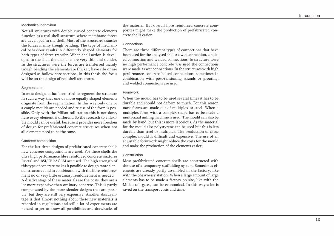
the material. But overall fibre reinforced concrete com-posites might make the production of prefabricated con-crete shells easier.
Connections
There are three different types of connections that have been used for the analysed shells: a wet connection, a bolt-ed connection and welded connections. In structure were no high performance concrete was used the connections were made as wet connections. In the structures with high performance concrete bolted connections, sometimes in combination with post-tensioning strands or grouting, and welded connections are used.
Formwork
When the mould has to be used several times it has to be durable and should not deform to much. For this reason most forms are made out of multiplex or steel. When a multiplex form with a complex shape has to be made a multi-axial milling machine is used. The mould can also be made by hand, but this is more laborious. As the material for the mould also polystyrene can be used but this is less durable than steel or multiplex. The production of these complex mould is difficult and expensive. The use of an adjustable formwork might reduce the costs for the mould and make the production of the elements easier.
Construction
Most prefabricated concrete shells are constructed with the use of a temporary scaffolding system. Sometimes el-ements are already partly assembled in the factory, like with the Shawnessy station. When a large amount of large elements has to be made a factory on site, like with the Millau toll gates, can be economical. In this way a lot is saved on the transport costs and time.
Mechanical behaviour
Not all structures with double curved concrete elements function as a real shell structure where membrane forces are developed in the shell. Most of the structures transfer the forces mainly trough bending. The type of mechani-cal behaviour results in differently shaped elements for both types of force transfer. When shell action is devel-oped in the shell the elements are very thin and slender. In the structures were the forces are transferred mainly trough bending the elements are thicker, have ribs or are designed as hollow core sections. In this thesis the focus will be on the design of real shell structures.
Segmentation
In most designs it has been tried to segment the structure in such a way that one or more equally shaped elements originate from the segmentation. In this way only one or a couple moulds are needed and re-use of the form is pos-sible. Only with the Millau toll station this is not done, here every element is different. So the research to a flexi-ble mould can be useful, because it provides more freedom of design for prefabricated concrete structures when not all elements need to be the same.
Concrete composition
For the last three designs of prefabricated concrete shells new concrete compositions are used. For these shells the ultra high performance fibre reinforced concrete mixtures Ductal and BSI/CERACEM are used. The high strength of this type of concrete makes it possible to design more slen-der structures and in combination with the fibre reinforce-ment no or very little ordinary reinforcement is needed. A disadvantage of these materials are the costs, they are a lot more expensive than ordinary concrete. This is partly compensated by the more slender designs that are possi-ble, but they are still very expensive. Another disadvan-tage is that almost nothing about these new materials is recorded in regulations and still a lot of experiments are needed to get to know all possibilities and drawbacks of

14
Prefabrication of concrete shells
1.3 Problem description and aimAn investigation to find a segmentation method that -is capable of making an efficient subdivision of the design of the shell surface and the development of a computational segmentation tool to use this method.An investigation of the possibilities and difficulties of -fibre reinforced composites for the use in prefabricat-ed shell structures.An investigation to the possible designs for the con- -nection between the elements in prefabricated con-crete shells.An investigation to the development of a flexible -formwork for the construction of double curved con-crete elements.
1.3.1 Problem descriptionNot many free formed shell structures in prefabricated concrete have been build. One of the reasons for this is that the design and production process of free formed shells in prefabricated concrete is not efficient enough to make the construction of these shells feasible in most cases.
One of the problems with the design process is that there is no segmentation method available that can be applied easily to all types of free form surfaces. Another problem is that the mechanical behaviour of shells in prefabricated concrete should become known and controllable.
The problems in the production process can be divided in difficulties with the formwork, the concrete reinforce-ment, and the connection system. The use of formwork is very inefficient when for every different element a new form is needed. Reinforcing a double curved element is very labour intensive and expensive. There is no system available with which the elements can be connected fast and easily and that can be used for the different connec-tions in the structure.
1.3.2 AimThe aim of this Master’s thesis is to find the difficulties and possibilities of the different aspects of the design and production process of prefabricated concrete shells and to come with possible solutions to overcome these difficul-ties to make the construction of prefabricated concrete shells more feasible.
To reach this goal the focus of this Master’s thesis will be on the following aspects:
An investigation of the mechanical behaviour of pre- -fabricated concrete shells, to find the possibilities and difficulties that have to be encountered during the design.

Introduction
15
methods that can be used as connection system are de-scribed and evaluated.
Chapter 7 ‘Production and construction’ considers the production of the elements, the construction of the shell, and some other aspects of the design and construction of the prefabricated concrete shells.
Part II Design process
After analysis of the different aspects of the design and construction of prefabricated concrete shells in Chapter 8 ‘Design process’ the design process of prefabricated con-crete shells has been analysed. This chapter shows in dif-ferent diagrams how the shell should be designed and op-timized.
In Chapter 9 ‘Geometry design tool’ the development of the design tool is described. The design tool generates the grid over the surface, defines the shape of the elements and controls the size, shape and curvature of the elements.
Part III Case study
In Chapter 10 ‘Case study’ a case study is performed in which the different aspects of the thesis come together.
Part IV Conclusions and Recommendations
In the ‘Conclusions and recommendations’ the conclu-sions of this thesis and some recommendations for further research are given.
This paragraph describes the method through which the aim of this Master’s thesis will be reached.
Part I Design Aspects
First the different aspects of the design and production process are investigated.
Chapter 2 ‘Mechanics’ gives a short introduction in shell mechanics and discusses different aspects of the structural analysis of (prefabricated) shell structures.
In Chapter 3 ‘Grid generation’ the existing grid genera-tion methods that can be used to generate a grid over the designed surface are investigated. This grid should be used for the segmentation of the shell surface.
In Chapter 4 ‘Concrete composites’ an overview of the of properties of different types of concrete, with a special fo-cus on (ultra) high performance and fibre reinforced con-crete, is given. In this chapter also some recently devel-oped fibre reinforced concrete mixtures are described. On the basis of the overview of the different types of the fibre reinforced concretes the most suitable concrete composi-tion and reinforcing method, for the fabrication of con-crete shells made out of double curved elements, has been defined.
Chapter 5 ‘Adjustable formwork’ describes the different studies to the flexible pin-bed mould, which is still in an experimental phase of its development. The characteris-tics of the adjustable formwork as it will be used in the proceeding of the thesis are defined.
In Chapter 6 ‘Edges and connections’ the formation of the edges and connections of the elements has been stud-ied. Different methods to create the edges of the elements are described and evaluated. In this chapter the different
1.4 Approach

16
Prefabrication of concrete shells

2. MechanicsBefore a structure can be build different calculations on the structures strength, stiffness and stability have to be made. This chapter discusses different aspects of the mechanical calculations of shell structures, like the membrane theory, the bending theory and finite element methods.
The Olanesti well station (1960). [64]

18
Prefabrication of concrete shells

Mechanics
19
In paragraph 2.2 different methods for surface defini-tion, based on geometrical or non-geometrical definition, are presented. After this an introduction about shell me-chanics will be given. In paragraph 2.3 the membrane and bending theory are discussed. Paragraph 2.4 discusses the finite element analysis. A short introduction of shell buck-ling is given in paragraph 2.5 and some specific character-istics of prefabricated shells are given in paragraph 2.6. At the end of this chapter structural optimization is discussed in paragraph 2.7 and some concluding remarks are given in paragraph 2.8.
2.1 IntroductionLoads applied to shell surfaces are carried to the founda-tion by the development of compression, tensile and shear stresses acting in the in-plane direction of the surface. The thickness of the surface does not allow the development of appreciable bending resistance. Thin shell structures are uniquely suited to carry distributed loads by in-plane forces or membrane forces.
At free-formed and geometrical defined surfaces the mem-brane theory often does not hold and some of the bending field components are produced to compensate the short-comings of the membrane field in the disturbed zone. This is also the case at the supports of shell and when point loads are applied on the shell surface. These disturbances have to be described by a more complete analysis which will lead to a bending theory of thin elastic shells.

20
Prefabrication of concrete shells
2.2 Surface DefinitionTranslation
Surfaces of translation are generated by sliding a plane curve along another curve, while keeping the orientation of the sliding curve constant. The latter curve, on which the original curve slides, is called the director of the sur-face. The other curve, that slices over the directrix, can be called the generator or generatrix of the surface.
Ruling
Ruled surfaces are generated by sliding each end of a straight line on their own generating curve, while remain-ing the straight line parallel to a prescribed direction or plane. The generated straight lines are not necessarily at right angles to the planes containing the generating direc-tor curves.
NURBS-techniques
NURBS, Non-Uniform Rational B-splines, are mathemati-cal representations on n-D geometry that can accurately describe any shape from a simple 2-D line, circle, arc or curve to the most complex 3-D organic free-form sur-face or solid. [19] Because of this flexibility and accuracy NURBS are ideal to describe free-form structures and they can be used in any process from illustration and anima-tion to manufacturing. NURBS-surfaces are specified by a complex combination of mathematical objects, formu-las and procedures, which interact to specify a new form in an iterative way. Designers that use these description techniques make use of special modelling programs, like Rhinoceros, to work with NURBS-techniques.
A NURBS curve is defined by its degree, a set of weight-ed control points and a knot vector. NURBS can be used to describe any curve. To describe any possible surface, instead of one parameter, two parameters are to be used in combination with a NURBS representation. By varying both parameters over their full ranges, a surface will be
A shell can be defined as a thin rigid three-dimension-al structural form enclosure in a volume bounded by a curved surface. A shell surface may assume virtually any shape. The geometry of a shell can also be described by the curved shape of the middle surface and the thickness of the shell. [3]
2.2.1 Geometrical defined surfacesGeometrical defined surfaces are surfaces that can be de-fined by means of parameters and mathematical functions. This makes it possible to describe irregular double curved surfaces. The more complex the shape, the more effort is required to describe the geometry in an accurate way. As the geometry is defined by mathematical formulas, the best and easiest way of representing the design is by making use of a computer. One method of geometrically specifying surfaces is to consider them as paths or traces of straight lines and curves. Examples of this are surfaces of revolution, translational surfaces or ruled surfaces. The main advantage of these surfaces is that they are rendered by line segments so there is already a grid generated that can be used to segment the surface into elements. Another way to geometrically specify surfaces relies on the special mathematics and procedures summarized under the name NURBS. These surfaces are not that easy to segment com-pared to the translational, rotational and ruled surfaces. There are also more advanced techniques like T-splines that are based on NURBS, but these are not discussed here.
Revolution
Surfaces of revolution are generated by the revolution of a plane curve, the meridional curve or generatrix, around an axis, the axis of revolution. Some examples of surfaces of revolution are conical shells, circular domes, spheres and torus shapes.
Figure 2.1 Example of a surface of revolution. [59]
Figure 2.2 Example of a surface of translation. [19]

Mechanics
21
The knot vector is a sequence of parameter values that determines where and how the control points affect the NURBS curve. The number of knots is always equal to the number of control points plus the curves degree plus one. The knot vector divides the parametric space in intervals, referred to a knot spans. The individual knot values are not meaningful by themselves; only the ratios of the dif-ference between the knot values matter.
The basis function describes how each geometric con-straint contributes to the final value of the curve. The values of the basis functions at any point along the curve indicate the amount of influence each control point has on the shape of the curve on that point. The resulting gen-eral equation of a curve can be described as the summing of the product of each geometric constraint and its basis function.
generated. By holding one parameter constant and vary-ing the other across the full range will generate a curve that is called an isoline. Frequently surfaces are visualised by using a set of evenly spaced isolines in each direction.
Curves can be of any degree (n), but the degree usually is 1, 2, 3 or 5. NURBS lines are of degree 1, NURBS cir-cles and parts of circles are of degree 2 and most free-form curves are of degree 3 or 5.
The control points determine the shape of the curve. Each point of a curve is computed by taking a weighted sum of a number of control points. The weight of each point var-ies according to the governing parameter. The weight of any control point is only non-zero in one interval of the parameter space. Within that interval the weight changes according to a polynomial function (the basis function) of a certain degree.
Directing plane
Generatrix
Displacement parallelto directing plane
Figure 2.3 Example of a ruled surface.
Figure 2.4 NURBS curves of different degrees.

22
Prefabrication of concrete shells
agents are earth gravity, air pressure or prestress. Physi-cal modelling processes are used to find an equilibrium for different types of situations.
Nature is seen as a source of inspiration for both archi-tects and civil engineers. When looking to optimization the evolution has produced many optimized structures in nature. In the world of nature structures are often opti-mized for withstanding forces of gravity. Structures in na-ture that have inspired engineers and architects in the past are for example cellular structures like honeycombs, drag-onfly wings, spider webs, bones and skeleton structures, sea shells, leaf structures and tree structures.
Hanging models are physical models that are shaped to their equilibrium state by gravity forces. Common used physical hanging models are wet cloth models, hanging chain models and hanging net models. Due to the used materials in hanging models, when hanging, they only contain tension forces. When inverting the model the
2.2.2 Non-geometrical defined surfacesThe non-geometric surface generation is another way to define surfaces. The most methods for non-geometric sur-face generation are form finding methods, which can be subdivided into experimental and analytical or numerical methods. Hanging nets and soap bubbles are well known examples of experimental form finding methods. Ana-lytical form-finding methods, such as the ‘force-density’ method and the ‘dynamic relaxation’ method are mainly the numerical counterparts of the physical, experimental methods. The objective of these form finding methods is to find an equilibrium state of a structure. When the right boundary conditions and form giving agents are applied irregular double curved surfaces are generated.
Physical form finding
Physical form finding methods are surface generation methods that make use of an actual model. Form finding processes require form giving agents, which have in this case a natural, physical character. Examples of form giving
Figure 2.7 The ribs Nervi used for his hangars are an example of a human ‘translation’ of the natural principle of ribbed structures, like in the Victoria amazonica. [24, 64]
Figure 2.6 Hanging model of the Sagrada Familia. [48]
Mirror line
Figure 2.5 Example of a wet cloth model.

Mechanics
23
To find the minimal surface of a membrane, the dynamic relaxation method solves the geometric non-linear prob-lem by equating it to a dynamic problem. Dynamic char-acteristics of the membrane need to be specified. For the form finding process, the pre-stresses in the membrane are fixed. The basis of the method is to trace step by step for small time increments the motion of each node of a structure until, due to artificial damping, the structure comes to a static equilibrium. The form finding process may start from an arbitrary geometry specification. The motion is caused by imposing a stress or force in some or all of the components of the structure. For load analysis, which must start from a correct initial or prestress equi-librium state the motion is caused by suddenly applying the loading.
The force density method uses a linear system of equations to model equilibrium states of non-linear systems such as pre-stressed cable nets under prescribed force density ra-tios. The method is based on force density ratios (cable force divided by cable length) that need to be defined for each element of the net. Different ratios give different equilibrium shapes for the net, the higher the force den-sity, the shorter the element for a given force. When the force densities for a node are equal and evenly distributed around the node, the minimal surface is found.
compression line or surface of the structure is found. Con-centrated loads on the model can be applied by hanging heavy elements in the model. Gaudi, for example, hung little bags filled with sand in his models to simulate con-centrated loads.
Soap films find the equilibrium shape of a minimal sur-face between preset (closed) boundaries. [24] With soap film modelling two main types of surfaces can be derived. The first one is to find the minimal surface for membrane structures and shells. Here the soap film shapes itself to a minimal surfaces between the set boundaries. The sec-ond one finding surfaces for pneumatic structures. Here an over-pressure is applied in the soap bubble and an internal (pneumatic) load is created to drive the forming process.
Structures that adapt to their environment according to a set of rules and strategies are called adaptive structures. They can be seen as physical form finding, since the struc-ture finds it own form by adapting to the environment, not in a scaled down model, but in full scale reality. The rules and strategies of the system are the driving force of the form finding process and the structure reaching its own structural optimum. [24]
Analytical form finding
Analytical form finding methods enable designers to pro-duce minimal surfaces, without making actual physical models. These methods are aimed at finding analytical minimal surfaces and are to be considered as the numeri-cal counterparts of the physical methods. Analytical form finding cannot be seen as a replacement for the physical form finding methods, they form an addition to them.
Figure 2.8 Soap film model. [24]
Figure 2.9 Pneumatic soap film model. [24]

24
Prefabrication of concrete shells
2.3 Membrane and bending theoryIn case of a pure membrane stress field only normal and longitudinal shearing stresses are produced, which are uniformly distributed through the thickness. The bend-ing stress resultants are small compared to the in-plane stress resultants for a thin shell. The stress resultants act-ing on a shell element, without the bending stress result-ants, are shown in Figure 2.10. The coordinate system can be placed on the middle surface according to the principal curvatures of the shell. But it is better to rotate the coordi-nate system in such a way that it can be placed in an arbi-trary direction, for example along an edge of the shell.
For an element three force equilibrium conditions be-tween the stress resultants and the load components can be set up. The positive action of the load components, act-ing on the middle surface of the shell element, is taken ac-cording to the positive directions of the three axes of the coordinate system.
The load component vector p is defined by:p = [px py pz]
T
Consistent with the three load terms in the load com-ponent vector p, the displacement vector u is defined by three displacements:
u = [ux uy uz]T
The displacements ux and uy are the displacements tangen-tial to the middle surface and the displacement uz is the displacement normal to the middle surface.
The membrane theory is based on the assumption that a thin shell produces a pure membrane stress field and that bending stress actions are not developed. The stresses are thus uniformly distributed. Because of the equality of the shearing stresses, the stress vector σ is defined by:
σ = [σxx σyy σxy]T
The stresses on the middle surface are thus described by the normal stresses, σxx and σyy, and by the shearing stress
Figure 2.11 Relation between the different vectors. [3]
2.3.1 Membrane theoryBecause of the small thickness-to-radius ratio of a thin shell, the flexural rigidity is much smaller than the ex-tensional rigidity. A thin shell subjected to external loads therefore mainly produces membrane stress resultants. The theory that describes this structural behaviour is called the membrane theory.
The basic assumption of the membrane theory is that a thin shell produces a pure membrane stress field and no bending stress actions are developed. The membrane the-ory is only applicable if certain boundary and loading con-ditions are met. These conditions are:
No sudden changes of the curvature are allowed. -No sudden changes of the thickness are allowed. -No concentrated loads allowed. -The reactions at the edges must be directed tangen- -tially to the middle surface and support arrangements must be made to allow this.
Figure 2.10 Stress resultants and load components on a shell element. [3]

Mechanics
25
The bending theory can be seen as an extension of the membrane theory. The load component vector p and the displacement vector u are still the same. But the other two vectors differ from the vectors used in the membrane theory. Due to the presence of the bending field compo-nents the bending stress resultant and the twisting stress resultant mxx, myy, and mxy have to be added to the stress resultant vector s. The strain vector e also changes, here the bending deformations κxx, κyy and ρxy are added. This results in changes in the relations between the vectors.
More information about the membrane theory can be found in ‘Theory of shells’ of J. Blauwendraad and J.H. Hoefakker [3].
σxy. The three stress resultants are obtained by integrating these stresses over the thickness t of the shell. Since the stresses are uniformly distributed this integration is equal to the multiplication of the stress vector with the thick-ness:
s = σt = [nxx nyy nxy]T
When it is assumed that the shell material behaves linear elastic, conform Hooke’s law, the strains are, correspond-ing to the stresses, uniformly distributed over the thick-ness of the shell. The deformation of the middle surface is therefore completely described by the strain vector e defined by:
e = [εxx εyy γxy]T
The deformation of the middle surface is thus described by the normal strains, εxx and εyy, and by the shearing strain γxy.
The relations between the different vectors are presented in Figure 2.11.
2.3.2 Bending theoryIn the regions where the membrane theory does not hold, some (or all) of the bending field components are pro-duced to compensate the shortcomings of the membrane field in the disturbed zone. These disturbances have to be described by a more complete analysis, which leads to the bending theory of thin elastic shells. [3]
When the bending field components are developed, they often only have a local range of influence and they attenu-ate rapidly. In many cases the bending behaviour is re-stricted to places where the membrane theory does not hold. Therefore the undisturbed and major part of the shell behaves like a true membrane. This unique property of shells is a result of the curvature of the spatial struc-ture.
Figure 2.12 Fixed edge conditions induce bending in the shell surface. The bending moments damp out rapidly. [22]
Figure 2.13 Relation between the different vectors. [3]

26
Prefabrication of concrete shells
2.4 Finite Element Analysismass and stiffness properties of the model.
The next stage of the FEA process is the analysis. The FEM conducts of a series of computational procedures involving applied forces, and the properties of the elements which produce a model solution. Such a structural analysis allows the determination of effects such as deformations, strains and stresses which are caused by applied structural loads such as force, pressure and gravity.
These results can then be studied using visualization tools within the FEA environment to view and to fully identify implications of the analysis. Numerical and graphical tools allow the precise location of data such as stresses and de-flections to be identified.
In a structural simulation, FEA helps tremendously in pro-ducing stiffness and strength visualisation and also in min-imizing weight and cost. FEA allows detailed visualisation of where structures bend or twist, and indicates the dis-tribution of stresses and displacements. The desired level of accuracy required and associated computational time requirements can be managed simultaneously. There are different commercial software packages, like ANSYS and DIANA, that provide facilities for generating the mesh, graphical display of input and output, which facilitate the verification of both input data and interpretation of the results.
Finite element analysis (FEA) is a computer simulation technique to analyse thin free-formed geometrical defined and form-finding shells and other structures. A common use of FEA is the determination of stresses and displace-ments in mechanical objects and systems. It uses a numer-ical technique called the finite element method (FEM). Development of the finite element method in structural mechanics is usually based on an energy principle such as the virtual work principle or the minimum total potential energy principle. The virtual work principle approach is more general as it is applicable to both linear and non-linear material behaviours.
In general, there are three phases in any computer-aided engineering task, like finite element analysis:
Pre-processing, defining the finite element model and -environmental factors to be applied onto it.Analysis, find the solution of finite element model. -Post-processing, analysis of the results using visuali- -zation tools.
The first step in using FEA, pre-processing, is constructing a finite element model of the structure that has to be ana-lysed. The input of a topological description of the struc-ture’s geometric features is required in most FEA pack-ages. This can be in either 1D, 2D or 3D form, although 3D models are predominantly used. The primary objective of the model is to realistically replicate the important pa-rameters and features of the real model. Once the finite el-ement geometric model has been created, a meshing pro-cedure is used to define and break up the model into small segments. In general, a finite element model is defined by a mesh network, which is made up of the geometric ar-rangement of elements and nodes. Nodes represent points at which features such a displacements are calculated. Ele-ments are bounded by sets of nodes, and define localized

Mechanics
27
If a shell is very sensitive to imperfections a different kind of finite element analysis is needed. In this geometrical nonlinear analysis. The load is applied in small increments for which the displacements are computed. Figure 2.5 shows the results of different finite element computations of a simply supported shallow dome.
In most cases the maximum load predicted with measured imperfections are within 10% of the experimental maxi-mum load. The maximum load is mainly affected by three types of imperfections; geometry, support stiffness and in-elastic effects. Experience show that of all geometrical im-perfections that are possible with the given amplitude the one affine to the buckling shape gives the smallest maxi-mum load. [24]
Buckling is one of the major failure modes of shell struc-tures. Shell structures are often highly sensitive to initial imperfections and therefore have buckling loads much lower than those computed for perfect structures. These imperfections include dents, residual stresses, temperature stresses, inhomogeneities, creep, shrinkage, eccentricity of loading and first order deformations. The shell structures that are very sensitive for imperfection are for example cylinders and radially compressed domes, hyppars on the other hand are not sensitive to imperfections. [24]
The value of the compressive load at which buckling oc-curs is called the critical load. For the stability of a shell, it is necessary to determine the critical buckling load. The critical load can be computed using formulas or a finite element program. This the load is reduced by a factor that takes into account the imperfection sensitivity. The result needs to be smaller than the design load that acts on the shell. This factor is experimentally determined and is of-ten called the ‘knock down factor’. Finite elements pro-grams can compute critical load factors and the associated normal modes. The real critical load is represented by the smallest load factor because a shell will buckle at the first opportunity it gets. For shell that are sensitive to imper-fections the maximum load factor might be as small as 1/6 of the critical load.
Figure 2.14 Shell finite elements analysis of a shallow dome. [24]
2.5 Shell buckling

28
Prefabrication of concrete shells
With a hinged connection there will always be a chain reaction of buckling and with a bending stiff connection there will always be the first type of buckling, where the shell fails but the elements still act together. The stiffness of the connection where the transition between these two types of buckling takes place differs for each design. To ensure that a shell structures fails on the first type of buck-ling, when it fails on instability, the stiffness of the con-nection has to be larger than the stiffness at the transition point.
It is most likely that a prefabricated concrete shell struc-ture fails at the joints between the different elements or in the shell close to the joints. So in order to perform a sound structural analysis the place and type of connections has to be known.
The mechanics of prefabricated concrete shell structures differ from these of in-situ concrete shell structures. The difference is that the prefabricated shells consist of dif-ferent prefabricated elements that are connected to each other on site and the in-situ shell is a monolithic struc-ture. The strength and stiffness of the connections have to be taken into account during the structural analysis of the shell, because they influence the possible failure modes, the strength and the stability of the shell structure.
In theory there are three different instability failure modes for prefabricated concrete shell structures [30]:
The shell fails, but the elements still act together as -one structure.A chain reaction of buckling between the elements -develops that makes the complete shell instable.Element failure due to buckling inside one element. -
2.6 Prefabricated concrete shell structures
Figure 2.16 Buckling behaviour of a shell with hinged connections. [30]
Figure 2.15 Buckling behaviour of a shell with bending stiff connections. [30]

Mechanics
29
structure with respect to the weight and overall stiffness or strength satisfying the equilibrium condition and the boundary constraints. It results in structures with modi-fied cross-sections of structural elements.
Material optimization is everyday practice for engineers. Material optimization is related to the optimal use of ma-terial in the structure. The goal is to achieve an optimum in material use and stress distribution.
The topology of a structure can be defined as the spatial ar-rangement of structural members and joints. Consequent-ly, topology optimization means varying the connectivity between structural members of discrete structures or be-tween domains of continuum structures.
Shape optimization refers to a technique in which the shape and thickness of a structure are optimized. The shape optimization method leads, by the aim of minimum of the total strain energy during form modification, to a membrane oriented design. By shape optimization the original design can be adapted in order to lower tension and bending stresses and progress to a more advantageous membrane state. This type of optimization is the most suitable for the optimization of shells.
Computational Optimization Algorithms
As the optimization of structures becomes dependent of an increasing amount of criteria, finding the best solution becomes very complicated. The development of compu-tational optimization algorithms has advanced spectacu-lar over the last decades. Various optimization algorithms with all kinds of application fields have been developed. Computational optimization algorithms often use a com-bination between different types of optimization, for ex-ample an integrated shape and topology optimization.
Structural optimization can be seen as the search for a bet-ter solution for a structural problem by generating addi-tional sensitivities with respect to non-considered param-eters. The optimized structure is better and more efficient than the initial structure. However this seems to be a very simple principle, the question how to define the optimiza-tion problem and to which extend it is executed is not.
In the optimization process first a shape is chosen for which the structural behaviour according to the given load cases and support conditions is evaluated. After the stresses, dis-placements, buckling loads and other safety requirements are checked a new and better design can be proposed by means of a sensitivity analysis. The process is repeated un-til the desired optimum is obtained.
Shape-sensitive structures like shells require high qual-ity design to obtain an optimal membrane design. Since in many situations this optimal shape is not obvious, the need for optimization techniques is clear. To fulfil the ba-sic membrane oriented design rules, a modification of the original design could substantially improve the structural behaviour reaching the ideal of a pure membrane stress in compression for all loading conditions. Optimization for shells results in a highly nonlinear optimization problem. This means that, in order to generate a reliable design by structural optimization, the nonlinear structural respons-es, like buckling or plasticity, must be considered.
A distinction can be made between size optimization, ma-terial optimization, topology optimization and shape opti-mization, even though these optimization techniques may have a lot of overlapping.
Size optimization refers to the optimization of the size of structural elements in a structure. The initial geome-try is not changed. Size optimization leads to an optimal
2.7 Structural optimization

30
Prefabrication of concrete shells
Optimization software must still be further developed as the bulk of investigations are concentrated on cross-sec-tional optimization, 2D shape optimization. The nonlinear behaviour is usually not taken into account as it greatly increases the complexity of the problem. This makes it difficult to optimize a shell structure, but the progression may foresee in sufficient optimizing shell software in the future. [17]
One of the most popular specific algorithms for structur-al optimization is Evolutionary Structural Optimization (ESO). ESO is a topology optimization method and thus involves consecutive removal of low stresses material un-til the maximum stress in the remaining material part is reached. The software makes use of finite element tech-niques to determine stresses.
Genetic algorithms are the most used general algorithms. The Darwinian based method generates every iteration new solutions by selection and crossover of previous ob-tained solutions in order to end up with a higher fitness generation. Random mutation of the new generation in-creases the change of reaching a global optimum. The process is repeated several times, keeping the size of the population constant.
Mechanics
31
The strength, stiffness and location of the connec- -tions influence the structural behaviour of the shell and have to be taken into account during the struc-tural analysis of the shell.
For shell structures the structural behaviour has to -be optimized to the ideal of a pure membrane stress in compression for all loading conditions. This proc-ess of optimization is very complex, because in most cases the most optimal shape is not obvious and there is a large amount of criteria that has to be taken into account.
Surfaces of revolution, translational surfaces and -ruled surfaces can not be used to define any free form surface, but the advantage of these surfaces is that they are defined by line segments so there is already a grid generated that can be used to divide the surface into elements.
NURBS can be used to define any free form surface, -but the segmentation of these surfaces can be more difficult compared to the segmentation of the other geometrical defined surfaces.
Finite element analysis, with the use of specialized -software, makes the structural analysis of shell struc-ture a lot easier. However, for the use of these nu-merical programs some basic knowledge of the un-derlying theories and the mechanical behaviour of the structure are still essential.
2.8 Conclusions

32
Prefabrication of concrete shells

3. Grid generation In order to be able to build a structure of prefabricated concrete elements the surface has to be segmented. There are different techniques that can be used for grid generation, which all have their strengths and weaknesses. In this chapter several of these techniques are considered and evaluated.
A part of a hybrid grid generated over the surface of an aircraft. [23]

34
Prefabrication of concrete shells

Grid generation
35
This chapter will provide a basic introduction into the fundamental concepts and approaches of grid generation techniques. First the terminology of grids and some grid requirements will be described in paragraph 3.2. The fol-lowing paragraphs will describe three fundamentally dif-ferent categories of grids and their generation techniques; structured grids, unstructured grids and composite grids. In the last paragraph some concluding remarks are given.
3.1 IntroductionLiseikin [12] defines a grid as a pre-processing tool or a foundation on which physical, continuous quantities are described by discrete functions and on which the differen-tial equations are approximated by algebraic relations for discrete values that are then numerically analysed by the application of computational codes. Grid generation tech-niques are commonly used for numerically solving physi-cal problems. These problems are described by partial dif-ferential equations and solved by finite element or finite difference methods. In these and other cases a grid is only a utility to reach a higher goal.
In this Master’s thesis the grid generation is used to seg-ment the surface of a free formed or a shell structure in elements that can be cast in concrete. The aim of the grid generation is to describe a geometrical complex continu-ous surface in a discrete way that is sufficiently accurate to represent a designed free formed surfaces.

36
Prefabrication of concrete shells
dimensional regions: structured and unstructured. These classes differ in the way in which the mesh points are lo-cally organized. When the local organization of the grid points and the form of the cells do not depend on their position but are defined by a general rule the mesh is con-sidered as structured. When the connection of the neigh-bouring grid nodes varies from point to point the mesh is called unstructured. The connectivity of structured grids is implicitly taken into account while the connectivity of unstructured grids has to be described explicitly by an ap-propriate data structure procedure.
The two fundamental different classes of grid give rise to three additional subdivisions of grid types: block struc-tured grids, overset grids and hybrid grids. These kind of grids possess to some extend the features of both struc-tured and unstructured grids.
3.2.2 Grid requirements With grid generation for traditional use the grid should discretize a domain or surface in such manner that the computation of physical quantities is carried out as effi-cient as desired. The accuracy, a component of the effi-ciency of the computation, is influenced by a number of grid factors. These factors are grid size, grid topology, cell shape and size and the consistency of the grid with the geometry and the solution.
Grid size and cell size
The grid size is indicated by the number of grid points, while the cell size implies the maximum value of the length of the cell edges. Grid generation techniques need to possess the ability to increase the number of grid nodes. At the same time the edge lengths of the resulting cells should be reduced in such a manner that they approach zero as the number of nodes tends to infinity.
3.2 Terminology and requirements of the grid
1
2
3
4
5
6
7
89
Figure 3.3 With unstructured grids the connection of neighbouring nodes varies from point to point.
3.2.1 Terminology There are two general notions of a grid in an n-dimension-al bounded domain or on a surface. One of these consid-ers the grid as a set of algorithmically specified points of the domain or the surface. The points are called the grid nodes. The second considers the grid as an algorithmi-cally described collection of standard n-dimensional vol-umes covering the necessary area of the domain or surface. The standard volumes generated by grid generation tech-niques, are referred to as grid cells. The boundary points of the one dimensional cells are called the cell vertices. These vertices are the grid nodes. Thus the grid nodes are consistent with the grid cells in that they coincide with the cell vertices. For cells in an n-dimensional domain or surface, there are commonly used n-dimensional volumes of simple standard shapes. (See Figure 3.1)
There are two fundamental classes of grid popular in the numerical solution of boundary value problems in multi-
i,j+1
i,j i+1,j
i,j+1
i,j i+1,j
Figure 3.2 The position of the grid points and the form of the cells in a structured grid are defined by a general rule.
Figure 3.1 Typical grid cells.
Grid generation
37
Consistency with geometry
The accuracy of the numerical solution of a partial dif-ferential equation and of the interpolation of a discrete function is considerably influenced by the degree of com-patibility of the mesh with the physical domain. The grid nodes must adequately approximate the original geom-etry, the distance between any point of the domain and the nearest grid node must not be too large. This distance must approach to zero when the grid size tends to infin-ity. Another requirement for consistency with the grid is concerned with the approximation of the boundary of the physical domain by the grid. There have to be a sufficient number of nodes, which can be considered as the bound-ary ones, so that the set of edges formed by these nodes models the boundary efficiently.
Element shape
The elements of which the surface can be composed of can have any shape. In representing 3D objects triangular and quadrangular meshes are the most common used.
Grid organization
The grids should have some organization of their nodes and cells. This organization should identify neighbouring points and cells.
Cell and grid deformation
The cell deformation characteristics can be formulated as some measures of the departure of the cell from a stand-ard, least deformed one. Standard elements are those with edges of equal length. The least distorted quadrilaterals are squares. Cell deformation is characterized through the as-pect ratio, the angles between the cell edges and the vol-ume or area of the cell.

38
Prefabrication of concrete shells
Method
The generation of boundary-confirming grids can be per-formed by a number of approaches and techniques. A boundary-fitted coordinate grid in the region Xn is com-monly generated first on the boundary of Xn and then suc-cessively extended from the boundary to the interior of Xn. On this basis there have been three basic groups of methods of grid generation developed:
Algebraic methods, which use various forms of inter- -polation or special functions.Differential methods, based mainly on the solution of -elliptic, parabolic and hyperbolic equations in a se-lected transformed region.Variational methods, based on optimization of grid -quality properties.
In the algebraic approach the interior points of the grid are commonly computed through formulas of transfinite interpolation. The simple algebraic methods enable the grid to be generated rapidly and the spacing and slope of the coordinate lines to be controlled by the coefficients in the transfinite interpolation formulas. In parts of the sur-face where the shape is more complicated, the algebraic approach does not give very good results. So the algebraic approaches are commonly used to generate grids in regions with smooth boundaries that are not highly deformed or as an initial approximation in order to start the iterative process of improving a grid.
For regions with arbitrary boundaries, differential meth-ods based on the solution of elliptic and parabolic equa-tions are commonly used. The interior coordinate lines derived through these methods are always smooth, being a solution of these equations, and thus discontinuities on the boundary surface do not extend to the region.
3.3 Structured gridsA grid can be classified as structured, when the local or-ganization of the grid points and the form of the cells do not depend on their position, but are defined by a general rule.
3.3.1 Boundary-confirming grids
Concept
The most popular and efficient structured grids are those whose generation relies on a mapping concept. According to this concept the nodes and cells of the grid in an n-dimensional region Xn are defined by mapping the nodes and cells of a reference grid in some standard n-dimen-sional domain Ξn with a certain transformation from Ξn to Xn. The domain Ξn is referred to as the logical or computa-tional domain. The domain Xn is referred to as the physi-cal domain. The idea is to choose a computational domain Ξn with a simpler geometry than that of the physical do-main Xn and then to find a transformation x(ξ) between these domains which eliminates the need for a non-uni-form mesh when approximating the complex geometry. If the computational domain and the transformation are well chosen the transformed domain should be accurate-ly represented by a small number of equally spaced mesh points. In practice there will be a trade off between the difficulty of finding the transformation and the number of uniformly spaced points required to find the solution with the desired accuracy.
The requirements imposed on the grid and the cell size are realized by the construction of a uniform grid in Ξn and a smooth function x(ξ). The consistency with the geom-etry is satisfied with a transformation x(ξ) that maps the boundary of Ξn onto the boundary of Xn.
Figure 3.4 Transformation of a complex geometry Xn to a simpler geometry Ξn by using a parametrisation x(ξ). [12]
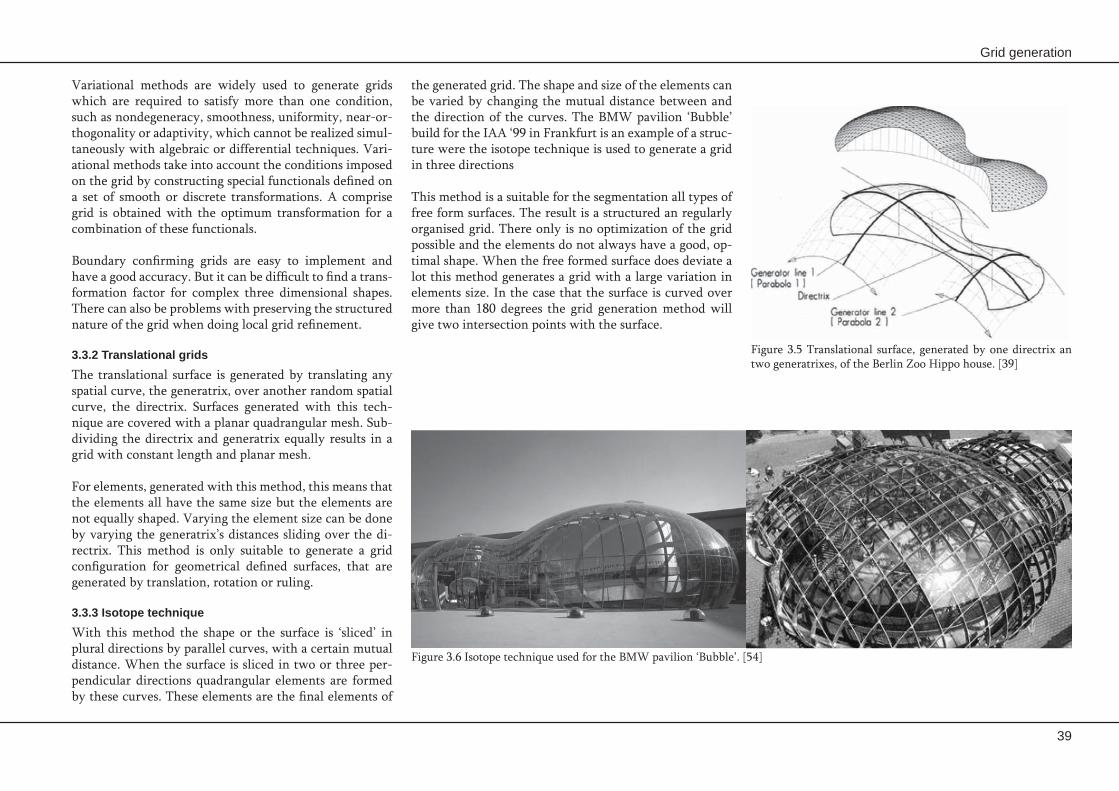
Grid generation
39
the generated grid. The shape and size of the elements can be varied by changing the mutual distance between and the direction of the curves. The BMW pavilion ‘Bubble’ build for the IAA ‘99 in Frankfurt is an example of a struc-ture were the isotope technique is used to generate a grid in three directions
This method is a suitable for the segmentation all types of free form surfaces. The result is a structured an regularly organised grid. There only is no optimization of the grid possible and the elements do not always have a good, op-timal shape. When the free formed surface does deviate a lot this method generates a grid with a large variation in elements size. In the case that the surface is curved over more than 180 degrees the grid generation method will give two intersection points with the surface.
Variational methods are widely used to generate grids which are required to satisfy more than one condition, such as nondegeneracy, smoothness, uniformity, near-or-thogonality or adaptivity, which cannot be realized simul-taneously with algebraic or differential techniques. Vari-ational methods take into account the conditions imposed on the grid by constructing special functionals defined on a set of smooth or discrete transformations. A comprise grid is obtained with the optimum transformation for a combination of these functionals.
Boundary confirming grids are easy to implement and have a good accuracy. But it can be difficult to find a trans-formation factor for complex three dimensional shapes. There can also be problems with preserving the structured nature of the grid when doing local grid refinement.
3.3.2 Translational grids The translational surface is generated by translating any spatial curve, the generatrix, over another random spatial curve, the directrix. Surfaces generated with this tech-nique are covered with a planar quadrangular mesh. Sub-dividing the directrix and generatrix equally results in a grid with constant length and planar mesh.
For elements, generated with this method, this means that the elements all have the same size but the elements are not equally shaped. Varying the element size can be done by varying the generatrix’s distances sliding over the di-rectrix. This method is only suitable to generate a grid configuration for geometrical defined surfaces, that are generated by translation, rotation or ruling.
3.3.3 Isotope techniqueWith this method the shape or the surface is ‘sliced’ in plural directions by parallel curves, with a certain mutual distance. When the surface is sliced in two or three per-pendicular directions quadrangular elements are formed by these curves. These elements are the final elements of
Figure 3.5 Translational surface, generated by one directrix an two generatrixes, of the Berlin Zoo Hippo house. [39]
Figure 3.6 Isotope technique used for the BMW pavilion ‘Bubble’. [54]

40
Prefabrication of concrete shells
3.4 Unstructured gridsUnstructured grids allow an instinctive approach to local adaptation, by either insertion or removal of nodes. Cell refinement in an unstructured grid can be accomplished locally by dividing the cells into smaller ones. Unstruc-tured grids also allow deleting grid cells in regions where the geometry is not that complex. Unstructured grids can be obtained with cells of arbitrary shape, but are generally composed of triangles (2D) or tet-rahedrons (3D). There are fundamentally three approaches for the generation of unstructured grids; octree approach, Delaunay procedures and advancing-front techniques.
3.4.1 Octree approach In the octree (3D) or quadtree (2D) approach the domain of the object is first covered by a regular Cartesian grid of cubic shells (3D) or squares (2D). Considering the two
Many free formed surfaces have a complex geometry that is not easily represented by structured grids. Structured grids lack the required flexibility and robustness for han-dling complex surfaces, and the grid cells may become too skewed and twisted.
Unstructured grids can be a solution for the problem of producing grids in regions with complex geometry. An unstructured grid can have irregularly distributed nodes and their cells are not obliged to have one standard shape. Beside this the connectivity of neighbouring grid cells is not subject to any restrictions, the cells can overlap or enclose each other. Unstructured grids provide the most flexible tool for the description of a shape’s geometry by a mesh.
Figure 3.7 Example of the octree approach. [23]

Grid generation
41
between the model boundary and interior cells without strict adherence to the boundary formed by the interior octants. Therefore they are not susceptible to the creation of poorly shaped elements caused by the boundary cells that just touch the model boundary.
The octree approach is a good method to develop an un-structured mesh over a free formed surface. The main drawback of the octree approach is the inability to match a prescribed boundary surface grid, so the grid on the sur-face is not constructed beforehand as desired but is de-rived from the irregular volume cells that intersect the surface. Another drawback is its rapid variation in cell size near the boundary. Since each surface cell is generated by the intersection of a hexahedron with the boundary there arise problems in controlling the variation of the surface cell size and cell shape.
3.4.2 Delaunay approach The Delaunay approach connects neighbouring points, of some specified set of nodes in the region of the shell sur-face, to form tetrahedral cells in such a way that the cir-cumsphere through the four vertices of a tetrahedral cell does not contain any other point. This definition is valid for a three dimensional application. For a two dimensional approach, the Delaunay triangulation, the definition re-duced to no points within the circumcircle through the three vertices of the triangular cell.
There are several ways of generating an unstructured grid based on the Delaunay criterion. The three most common used are discussed below.
Voronoi Diagram
For a random set of points the Voronoi diagram marks off the region of space that lies closer to each point than the other points. In Figure 3.9 the lines show the Voronoi dia-gram, forming a tessellation of the space surrounding the points. Each Voronoi tile (hatched area around P) consists
dimensional case the square is subdivided into four equal quadrants. Each quadrant is examined to determine if it is subdivided based on the given subdivision criteria. A common used subdivision criteria is to refine the cell if it contains any of the boundary of the object. This subdivi-sion is repeated until the subdivision criteria are satisfied throughout the domain. This subdivision process defines a tree structure where the nodes in the tree correspond to rectangles at a particular point in the process.
There are a variety of options available to create elements once the tree has been defined. The tree cells that are in-terior to the domain of the object are meshed with proce-dures that take specific advantage of the simplicity of the cell’s topology and shape, and use the knowledge of the tree structure to determine the influence of neighbouring cells on the mesh within the cell of interest.
Meshing of the cells that contain portions of the boundary of the object is a more complex process. There are differ-ent methods for meshing the boundary cells of the grid:
Apply an element removal procedure starting from a -basic cell level boundary representation. Development of a Delaunay triangulation based on -the mesh vertices of the cell level boundary repre-sentation, which is followed by an algorithm that en-sures that the resulting surface triangulation is topo-logically compatible and geometrically similar.Creation of tetrahedral elements from a given surface -triangulation using an element removal procedure.Creation of hexahedral elements to fill the region be- -tween the interior cells and the model boundary.
The first two procedures operate strictly accounting for the intersections of the model and cell boundary enti-ties, they are vulnerable to small, poorly shaped elements caused by boundary cells that just touch the model bound-ary. The last two procedures create elements in the region
Figure 3.8 Delaunay triangulation with empty circumcircles.
Figure 3.9 Voronoi diagram. [23]

42
Prefabrication of concrete shells
Figure 3.10 Different stages of the Boyer-Watson algorithm. In the first stage (a) a new grid node is added and the cells whose circumcircle contain this point are identified. In the next stage (b) the found cells are removed and in the last stage (c) a new triangulation is formed. [12]
To obtain a Delaunay triangulation, the following algo-rithm is followed:
A new grid node is added to the triangulation, chosen -from a given set of points or is found in accordance with some user-specified rule to supply new vertices.All the existing cells whose circumcircle contain the -new grid point are identified. The found cells are removed, which creates a convex -cavity, the so called Delaunay or inserting cavity.A new triangulation is formed by joining the new -point to all the boundary vertices of the inserting cavity.
This algorithm is repeated until the necessary require-ments for grid quality have been satisfied.
Edge-swapping algorithm
The edge swapping algorithm makes use of the equian-gular property of a Delaunay triangulation, which states that the minimum angle of each triangle in the mesh is maximized. [12] Assuming there is some triangulation of a given set of points, the swapping algorithm transforms
of the region of the plane that is closer to that point than to any other point. The edges of the tiles are formed by the perpendicular bisectors of the lines connecting neigh-bouring points. Each vertex of the Voronoi diagram is the circumcentre of the triangle formed by three points. This unique triangulation is the Delaunay triangulation and is such that the circumcircle through each triangle contains no points other than its forming points.
Problems with this approach can rise in the triangulation procedure when three points of a potential triangle lie on a straight line or when four or more points are cyclic. These cases van be eliminated by rejecting or slightly moving a point that causes the problem.
Bowyer-Watson Algorithm
The Bowyer-Watson algorithm is an incremental tech-nique that triangulates a set of points in accordance with the requirement of the Delaunay triangulation. The algo-rithm starts from some initial triangulation. This initial triangulation commonly consists for a two-dimensional domain of a square divided into two triangles which con-tain the given points.

Grid generation
43
Evaluation
The Delaunay triangulation is very popular in practical applications because Delaunay triangles are nearly equi-lateral. Beside this the maximum angles are minimized and the minimum angle is maximized. These properties give some grounds to expect that the grid cell of a Delau-nay triangulation are not too deformed.
A major drawback of the Delaunay triangulation are the problems that arise with describing fixed boundaries or edges. To overcome this disadvantage some grid genera-tion approaches of constrained triangulation are devel-oped. In the first approach the Delaunay property is over-ridden at points close to the boundaries and consequently the previously generated boundary grid remains intact. In the second, the points are added in the form of a skele-ton to ensure that breakthroughs of the boundary do not occur. The last method is to recover the boundary edges which are missing during the process of Delaunay trian-gulation, after the triangulation is completed.
3.4.3 Advancing-front technique With the advancing front technique the grid is generated by building cells progressively one at a time and marching from the boundary into the volume by successively con-necting new points to points on the front until all previ-ously unmeshed space is filled with grid cells. [12] Such a procedure allows an unstructured grid to be generated au-tomatically from a surface representation of the complex geometry. The advancing-front technique needs some ini-tial triangulation of the boundaries of the geometry, this triangulation forms the initial front. The marching process includes the construction of a new cell, which is built by connecting either some points on the front or connecting a newly inserted point with the vertices of a suitable face on the front.
it into a Delaunay triangulation by repeatedly swapping the positions of the edges in the mesh in accordance with the equiangular property. For this purpose, each pair of triangles which constitutes a convex quadrilateral is con-sidered. This quadrilateral produces two of the required triangles when one takes the diagonal which maximizes the minimum of the six interior angles of the quadrilat-eral, as shown in Figure 3.11. Each time an edge swap is performed, the triangulation becomes more equiangular. The end of the process results in the most equiangular tri-angulation. The minimum angle of each triangle in the mesh is maxi-mized. This has the advantage that the resulting mesh is optimal for the given point distribution, in that there are usually not many extremely skewed cells.
Insertion of new points
All Delaunay triangulation methods assume that the points to be triangulated are already known. These methods thus only address half of the grid generation problem. There are two approaches for sequential point insertion which provide a refinement of planar Delaunay triangulations. For both methods some measures of the grid quality, such as the minimum angle, the ratio of maximum to minimum edge length, and the ratio of circumradius to inradius, are used to generate new points. The approaches are:
Point placement at the circumcentre of the maximum -triangle; A simple but effective approach that consists in placing a new point at the circumcentre of the cell with the largest circumradius and iterating this proc-ess until the maximum is less than some prescribed threshold. Voronoi-segment point insertion; This approach con- -sists in inserting a point along a segment of the Voro-noi tessellation. This technique provides an opportu-nity to generate one or possibly several new triangles having the prescribed size of the final grid.
Figure 3.11 Triangulation which maximizes the minimum angle of the interior angles of the quadrilateral. [12]

44
Prefabrication of concrete shells
vertex for the new tetrahedron. The current triangle is then removed from the list of front faces, since it is now obscured by the new tetrahedron. This process continues until there are no more faces in the list of front faces and until the domain is fully meshed.
The advancing front technique offers the advantage of high-quality point placement and integrity of the bound-ary. The efficiency of the front advancing process large-ly depends on the arrangement of the grid points in the front, especially at sharp corners. If large variations in grid spacing are present, grid generation by the advanc-ing front method can become problematic. The advancing front technique is quite complex and therefore time con-suming, due to the need for searching nearby nodes and edges and the complex intersection checking.
To generate cells with acceptable angles and lengths of the edges, the advancing front method requires a prelimi-nary specification of local grid spacing and directionality at every point of the computational grid. The spacing is described by defining two orthogonal directions (for 2D) together with a length scale for each direction. The pro-cedure proceeds by listing all faces which constitute the front and then selecting an appropriate edge on the front. The choice of the edge is very important, since the quality of the grid may be affected by this choice. The face where the grid spacing is the smallest is selected. A collection of vertices on the front which are appropriate for connection to the vertices of the selected face to form a tetrahedron is searched. A new point is created which is consistent with the ideal position determined from the background in-formation about grid spacing and directionality. Each se-quential tetrahedron formed by the face and the ordered points is then checked to find out whether it intersects any face in the front. The first point which satisfies the test and gives a tetrahedron of good quality is chosen as the fourth
Figure 3.12 Different stages of the advancing front technique. [23]

Grid generation
45
3.5 Composite gridsThe free formed surface can be divided into sub do- -mains in which the properties of the surface are simi-lar. Different layouts of a structured grid are required to adequately describe the complex surface.The free formed surface behaves in a non uniform -way, zones of smooth and rapid variation of different scales may exist.
The requirement of mutual positioning or communication of adjacent grid blocks can also have a considerable influ-ence on the construction of locally structured grids and on the accuracy of the approximation of the free formed surface by the grid. There are several ways of connecting the different blocks. The coordinate lines defining the grid nodes of two adjacent blocks do not need to have points in common. The blocks can also be joined smoothly or non-smoothly. If the coordinate lines do not have to join this considerably simplifies the algorithm for constructing the grid in a block. If a smooth transition is desired this causes serious difficulties for structured mesh generation.
The choice of the topology in a block depends on the ge-ometry of the computational region and the choice of the transformation of the region into the block and has a con-siderable influence on the quality of the grid. There are two ways of specifying the computational region for the block:
As a complicated polyhedron which maintains the -schematic form of the block sub-domain.As a solid cube or a cube with cuts. -
With the first approach the problem of constructing the coordinate transformation x(ξ) is simplified and this meth-od is often used to generate a single block grid in a com-plicated domain. The second approach is based on a sim-ple geometry of the computational domain but requires a complicated transformation x(ξ). The choice of the grid
With the composite grid generation strategy the geomet-ric complex region division is divided into a few contigu-ous sub-domains, which can be considered as the cells of a coarse unstructured grid. After this subdivision, separate structured grids are generated in each sub domain. Com-bining these local grids, a mesh will be acquired that is referred to as a composite grid. The grids are locally struc-tured at the level of the individual blocks, but globally un-structured when considered as a collection of blocks. This strategy allows that the most appropriate grid configura-tion can be applied in each region.
The generation of the composite grid is a combination of the earlier described structured and unstructured grid generation techniques. For composite grids the main chal-lenge is to connect the different structured grids in such a way that the geometric complex surface is efficiently described. The three methods that are most common are block structured grids, overset grids and hybrid grids.
3.5.1 Block structured grids A common idea in a block structured grid technique is the use of different structured grids or coordinate systems in different regions, allowing the most appropriate grid con-figuration to be used in each region. Grids of this kind can be considered as locally structured at the level of an indi-vidual block, but globally unstructured when viewed as a collection of blocks. Block structured grids are consider-ably more flexible in handling complex geometries than structured grids. However the generation of the block structured grids may cost considerably more time and user interaction than the single block structured grid. The main reason for using multiblock grids rather than single block grids are:
The geometry of the free formed surface is complicat- -ed. It has for example multiple connected boundaries, cuts and cavities.
Figure 3.13 The different types of connection between contiguous blocks in a block structured grid; a) discontinuous, b) & c) non-smooth, and d) smooth. [12]

46
Prefabrication of concrete shells
3.5.3 Hybrid gridsHybrid numerical grids are meshes which are obtained by combining both structured and unstructured grids. These grids avoid the problems with overset grids by replacing the overlaid regions with an unstructured grid connect-ing the structured grids. Hybrid grids are formed by join-ing structured and unstructured grids on different parts of the region or surface. A structured grid is generated about each chosen boundary segment These structured grids are required not to overlap. The remainder of the domain is filled with the cells of an unstructured grid.
This combination of grid types not only allows the ben-efits of both structured and unstructured grids to be at-tained simultaneously, but also allows high grid quality to be achieved throughout the domain due to the appropriate use of each element type.
topology in a block depends on the structure of the solu-tion, the geometry of the domain and on the topology of the grid in adjacent blocks, in case of continuous or smooth grid lines. For complex geometries it is difficult to choose the grid topology of the blocks, because each block in the surface has its own natural type of grid topology, but these topologies are often not compatible to each other.
3.5.2 Overset gridThe partition of block structured grids into different do-main has the restriction that the different blocks have to be adjacent to each other. Overset grids are released from this restriction and the different blocks are allowed to overlap each other. The global grid is obtained as an as-sembly of structured grids which are generated separately in each block. These structured grids are overset on each other with data communicated by interpolation on over-lapping areas of the block.
The fact that the blocks are allowed to overlap signifi-cantly simplifies the problem of the selection of the blocks covering the surface geometry. But for generating a grid over a free form surface the overset grid approach seems to be unfit, due to the overlapping areas of the grids.
Figure 3.15 A fragment of a hybrid grid. [12]
Figure 3.14 Example of an overset grid. [12]
Grid generation
47
Unstructured grids provide the most flexible tool for -the discrete description of a complex geometry. This flexibility at the same time leads to the main draw-backs of unstructured grids, the grids are complex, there is no predictable organisation and the elements are not of the same size.
Composite grids are a combination between struc- -tured and unstructured grids. This strategy allows that the most appropriate grid configuration can be applied in each region an the positive features of both structured and unstructured methods are combined.
From a theoretical point of view it can be concluded -that there is no optimal grid generation technique that results in the best grid for every surface
The best suited grid generation technique depends on -the geometry of the surface, the architectural design and the structural layout.
The grid generation method will be used to generate -a grid over a free form surface that forms the basis of the division of the surface into elements.
A structured grid can be used to describe any com- -plex double curved surface, but the complexity of a surface determines the degree of suitability for apply-ing a fully structured grid generation technique.
The translational grid produces double curved ele- -ments that all have approximately the same size. The shape of the elements is generally not to deformed. The main drawback is that it can only be used for geometrically defined surfaces generated by transla-tion, rotation or ruling.
The isotope technique can also be used to describe -any complex double curved surface and generates double curved elements. But the shape of the gener-ated elements is not always optimal.
3.6 Conclusions

48
Prefabrication of concrete shells

4. Concrete CompositesThis chapter gives an overview over the recently developed concrete composites with high strength and fibre reinforcement. It also describes the possibilities and difficulties of these new composites.

50
Prefabrication of concrete shells

Concrete composites
51
4.1 IntroductionRecently many different types of (ultra) high performance fibre reinforced concrete have been developed. In this chapter a general description of steel reinforced concrete, self compacting concrete, high performance concrete and fibre reinforced concrete has been given. In paragraph 4.6 it has been tried to describe the most important types, preferences and possible applications of fibre reinforced concrete. In paragraph 4.7 a general overview has been created whether different types fibre reinforced concrete are applicable for prefabricated shells. On the basis of this overview the best concrete composition and reinforcing method for the fabrication of concrete shells made out of double curved elements has been defined.
Concrete is a building material that is characterised by a good workability, freedom of design, a high compressive strength and low cost. The main disadvantages of the ma-terial are the low flexural and tensile strength, which is roughly only one tenth of the compressive strength. Ten-sile and bending forces in the concrete can be absorbed by an adequate reinforcement. In general steel bars are used as reinforcement. To protect the reinforcement against corrosion a minimum thickness of the concrete cover is required. This thickness varies between 20 to 50 mm and depends on the exposure class. This results in a minimum thickness of reinforced concrete elements of approximate-ly 60-120 mm.
In slabs the reinforcement is applied in mats made out of steel reinforcing bars. When the elements are double curved this gives an extra difficulty placing the reinforce-ment, because the reinforcing mats have to be bend by hand in order to follow the curvature of the mould, so it is time- and labour intensive to reinforce these elements.
For prefabricated concrete shells slender and thin elements with double curvature are preferred. This kind of elements are hard to make with regular steel reinforced concrete. A solution for this might be found in fibre reinforced high performance concrete. For example textile reinforcement consisting of polymers, carbon or alkali-resistant glass fi-bres can be used to replace the steel reinforcement. Due to the improved corrosion behaviour these elements can be very thin and still have a high load carrying capacity.
Figure 4.1 Curved reinforcement for a prefabricated concrete element. [20]

52
Prefabrication of concrete shells
To make the failure of the concrete less brittle reinforce-ment can be added, so according to the regulations always a minimum amount of reinforcing bars have to be added to prevent brittle failure.
The tension strength of normal strength concrete is very low, only 1/10 to 1/15 of the compression strength. So in most calculations the tension strength of the concrete will be neglected. In order to be able to take tension forces steel reinforcing bars are added to the concrete members. The tension force in the concrete members is almost com-pletely taken by the steel reinforcement.
Reinforced elements are designed in such a way that the reinforcement is applied on places where tension is ex-pected. In this way the bending moments in the element can be taken in an efficient way. When a force is applied the concrete takes the compression force and the rein-forcement takes the tension force, after the development of some micro cracks. This is can be seen in Figure 4.3, where the stress and strain distribution in a reinforced concrete beam in bending is shown. The tension in the lower part of the beam is completely taken by the steel reinforcement and the compression in the top of the beam is taken by the concrete.
Due to shear forces in concrete elements diagonal cracks can occur, which can cause brittle failure if no measures are taken to prevent this. When the shear force is too large to be taken by the concrete reinforcement has to be ap-plied. It seem logical to apply diagonal reinforcement, be-cause in this way the cracks are crossed perpendicularly. This is however not workable in practise, so vertical stir-rups are applied to reinforce the concrete for shear forces.
4.2 Steel reinforced concrete
Strain Stress
Figure 4.3 The strain and stress distribution of a reinforced concrete beam in bending show that the tension in the lower part of the beam is taken by the reinforcement and compression in the top is taken by concrete.
Concrete is a hard material that is capable of taking large compression forces and consists of a mixture of cement, sand, gravel and water in the right proportions. This mix-ture hardens by the chemical reaction between cement and water.
The ratio in which the water and cement are mixed into the concrete influences the strength of the concrete, the high-er the water-binder ratio the lower the concrete strength. The amount of water also influences the workability of the concrete mixture, more water is needed for a better workability. With a large water binder ratio not all water is used to react with the cement grains, so some water is still left in the pores of the concrete and can cause micro cracks due to shrinkage of the concrete. An optimum be-tween strength and workability has to be found. Normally a water cement ratio of 0,4 or a little higher is used. Then most of the water can react with the cement and the mix-ture has still a good workability. Often a superplasticizer is added to the mixture to improve the workability of the concrete, and be able to reduce the water binder ratio.
After casting the concrete needs to be compacted with vi-brating energy to let the air bubbles out of the mixture, and minimize the air that stays in the concrete.
The arrangement of the grains in the concrete makes that only a small matrix force is needed to take a large verti-cal force. The grains are, in normal strength concrete, the strongest part of the concrete. Failure of the concrete un-der compression will start at the contact surface between the additive grains and the cement stone at the moment the tension force cannot be taken any more and micro cracks develop. The micro cracks grow to macro-cracks and end up in failure of the element. This kind of fail-ure can occur very suddenly without any warning in the form of large cracks or large deformations of the concrete.
Figure 4.2 Simplified scheme of the force flow in concrete. A large compression force results in a much smaller tension force on the contact surfaces between the grains.

Concrete composites
53
4.3 Self compacting concreteInternal friction can be decreased even more by adding fine fillers and superplasticizer to the mixture. Fine fillers have a grain diameter that lies between the diameter of fine sand and the diameter of cement grains. This makes the concrete structure very dense and because of this dense packing the concrete strength will automatically be relatively high.
Self compacting concrete is also beneficial for fibre rein-forced concrete elements. The fluidity of self compacting concrete can be used in the prefab-concrete industry very well to influence the orientation of the fibres in the con-crete. With a controlled flow of the mixture during casting the fibres can orientate themselves in the right direction, which can also be the direction where tension forces are present in the construction. In this way the tension prop-erties of the fibres can be optimized.
Compacting concrete is a very unpleasant activity and it saves a lot time when it can be eliminated from the cast-ing process. To improve working qualities on the site and save time self compacting concrete was developed. Self compacting concrete (SCC) is very fluid and does not re-quire any compacting after casting. It has such a viscosity that air bubbles can migrate to the outer surface of the fresh concrete, without adding any compacting energy to the concrete. [10] Since its introduction the use of SCC is widely spread. It is nowadays used for almost all prefab-ricated concrete elements. Another field of application is the use on site for constructions where compacting of the concrete causes problems due to the shape of the elements, the density of the reinforcement or the accessibility of the mould.
The idea of SCC is to add a little more cement paste than necessary for good functioning of the hardened concrete. This extra cement paste forms a thin layer around the ag-gregate grains that makes them ‘float’ in the mixture. (See Figure 4.4) The thin lubrication layer around the grains decreases the shear stresses and makes the material very fluid. Because these layers are very thin they do not influ-ence the characteristics of the hardened concrete.
Figure 4.4 ‘Floating grains’ in self compacting concrete. [41]

54
Prefabrication of concrete shells
Reduce the water-binder ratio
In normal strength concrete a water/binder ration of about 0,4 is used. For high strength concrete the water/binder-ratio is reduced and lies between 0,12 and 0,20. In this way all the water in high strength concrete is used for the hydration of the cement. The remaining cement particles, that are not hydrated, act as fillers. To keep the mixture workable superplasticizer is added.
Addition of fibres
A negative aspect of the dense and high strength matrix is that it results in a very brittle material, with a higher brittleness than normal strength concrete. To overcome this defect and increase the deformation ability short thin fibres can be added to the concrete mixture. All ultra high performance concrete mixtures that are developed con-tain fibres.
Improvement of the micro structure
The microstructure can be improved by heating the struc-ture at an optimum temperature, usually at 90 0C for two days during hardening. This enhances the pozzolanic re-action of micro silica and results in a reduction of the po-rosity. The porosity can be reduced even more, to almost zero, when the heat treatment is combined with the ap-plication of compression. [13]
4.4 (Ultra) high performance concrete
Figure 4.5 Optimal packing arrangement where each grain fills the voids between the larger grains.
Figure 4.6 The discontinuous distribution of grain sizes of high performance concrete compared to the continuous distribution of grain sizes of ordinary concrete. [4]
High performance concrete (HPC) is concrete with a com-pressive strength of at least 65 N/mm2. When the char-acteristic compressive strength is more than 115 N/mm2 the concrete is called ultra high performance concrete (UHPC). Characteristic for UHPC is the fast and high strength development and the dense structure which gives a very durable concrete. The basic principles of mixture design of (ultra) high performance concrete are described below.
Improve the homogeneity
The homogeneity of the material is improved by reduc-ing the size of the coarse aggregates. In this way the vari-ation in the stress in the hardened concrete is reduced. The coarse aggregates are replaced with very fine sand or stronger materials like bauxite, with a maximum size up to 8 mm.
Optimize the packing arrangement
To optimize the packing density of the mixture fine fillers, such as silica fume and fly ash, are added to fill the voids between the cement particles. This maximizes the pack-ing density of all grains so that each class fills the voids of the larger class. (See Figure 4.5) To get an optimal mixture the distribution of the grain sizes is discontinuous and not continuous like with normal strength concrete. (See Fig-ure 4.6) The sizes of the aggregates vary between a limited ‘diameter domain’, which differ in such way that the voids between the larger grain are filled by a smaller material and an optimal mixture is formed.

Concrete composites
55
the concrete should be high enough to prevent pull-out failure of the fibres. Multiple cracking is the phase when more cracks occur at a constant stress level that is equal to first crack stress. The stress-strain curve of this phase is horizontal or slightly ascending. After multiple crack-ing the concrete matrix is divided by parallel cracks and an additional tensile load will cause stretching or pull-out of fibres.
For continuous and aligned fibres the overall mechani-cal behaviour of FRC composite can be described in three stages of the tensile stress versus strain curve (Figure 4.8) by the ACK-model:
The elastic range;1. Multiple cracking;2. Post-multiple cracking.3.
The ACK-model is the first analytical model for the devel-opment and growth of multiple cracks in continuous fibre concrete. The actual concrete composite consists of short fibres with a nonlinear orientation trough the matrix, in-stead of long aligned fibres in the AKC-model, this influ-ences the characteristics of the concrete. The efficiency of the fibre reinforcement depends on the fibre length, the fibre orientation and the fibre-matrix shear bond strength. The fibre efficiency is expressed in terms of an efficiency factor.
Different types of fibres have a different influence on the concrete properties. Long fibres have a better bond-ing than short fibres and can therefore have an effect on wider cracks. Long fibres can increase the ductility and bearing capacity of the concrete by bridging larger macro cracks. Short thin fibres on the other hand are better for increasing the tensile strength by bridging micro cracks in the concrete.
4.5 Fibre reinforced concreteFibre reinforced concrete (FRC) is concrete to which fi-bres are added to improve the concrete characteristics. Most fibre reinforced concretes are also high or ultra high performance systems.
Fibres are most commonly discontinuous and random distributed through the cement matrix. They are not as efficient in withstanding tensile stresses as conventional reinforcement. But because they are more closely spaced than conventional reinforcement they are better in crack control and improve the ductility of the concrete. It is im-portant to recognize that in general, fibre reinforcement is not a substitute for conventional reinforcement
Before matrix cracking the reinforcing fibres do not play a major role in the strength resisting system of the fibre composites. In fibre reinforced composites the fibres have the most important role in the post cracking zone. In this phase the fibres bridge across the cracked matrix. They can serve two functions in a well-designed composite:
They may increase the strength of the composite 1. over that of the matrix by providing a mean of transferring stresses and loads across cracks. This implies an ascending stress-strain curve after first cracking and this behaviour is referred to as strain hardening.
They increase the toughness of the composite 2. by providing energy absorption mechanisms, related to the debonding and pull-out processes of the fibres bridging the cracks. This occurs even when the stress-strain curve is descending after first crack (strain softening).
As cracking occurs the load is transferred to the fibres in the concrete. To prevent failure the load-bearing capacity of the fibres should be greater than the load on the com-posite at first crack and the bond between the fibres and
Figure 4.7 Schematic description of strain softening (left) and strain hardening (right) in tension. [1]
Figure 4.8 Schematic description of the stress-strain curve, based on the ACK-model. [1]

56
Prefabrication of concrete shells
Fibre degradation can result from direct attack of the fi-bres by the cement matrix due to a reaction with the high-ly alkaline pore water or from attack by an external agent which penetrates through the cement matrix into the fi-bre. Alkaline degradation occurs in glass fibres and natu-ral fibres, while degradation due to penetration of external agents is more characteristic for steel fibres. The mecha-nisms are different, but the outcome is the same, namely reduction in strength and toughness over time.
The microstructure is sensitive to changes at the fibre-ma-trix interface over time. Due to continued hydration and densening of the interfacial transition zone. The influence of the micro structural changes could be particularly large in the case of thin filaments whose surface area is rath-er large. The bond in such systems is close to the critical bond, where transition from fibre pull-out failure to fibre fracture may occur. A result of this effect is an increase in strength and reduction in toughness over time.
The workability of the concrete is strongly influenced by the length of the fibres. It is not possible to put a large amount of long fibres in the concrete, while this is pos-sible for short fibres. The fibre content of short fibres can be increased up to 5 to 10 %, for long fibres the maximum fibre content is about 2,5%.
Long term performance
The special structure of fibre reinforced concrete and the characteristics of the fibres in the concrete may lead to long-term effects which are different from those of con-ventional concrete.
Changes in properties can be accounted for by several processes:
Fibre degradation due to chemical attack; -Fibre-matrix interfacial physical interaction; -Fibre-matrix interfacial chemical interactions; -Volume instability and cracking. [1] -
Figure 4.9 The influence of short fibres on bridging micro cracks a) and long fibres on bridging macro cracks b). [13]

Concrete composites
57
by creating fibres with a more complicated geometry like bends and waves.
Steel fibres corrode at the concrete surface. In practice it turned out that this has no negative consequences on the durability of the construction. The inner side of the con-crete is not damaged but with visual concrete this has to be taken into account. An alternative is the use of stainless steel or thermal galvanised fibres.
Synthetic fibres
The most used synthetic fibres are made of polypropyl-ene. Because of the size and weight of the fibre millions of fibres are present in a cubic metre of concrete, with a normal dose of about 0,9 kg per m3. Good fibres have some sort of coating to improve the mixing ability, to prevent air encapsulation and to improve the bonding properties of the fibres. Synthetic fibres are not visible on the con-crete surface.
There are two sorts of polypropylene fibres; fibrillated fi-bres and monofilament fibres. Fibrillated fibres are thicker than monofilament fibres and are applied in the form of mats. Monofilament fibres are thinner, can have a curva-ture and are applied as single fibres.
Synthetic fibres have no influence on the strength charac-teristics of the concrete and cannot be used as replacement of conventional reinforcement. But they do strengthen the structure of the concrete which has the following ben-efits:
Prevention of plastic shrinkage cracks; -Improvement of the permeability of the concrete; -Higher impact resistance of the concrete; -Higher durability for freezing and thaw salt; -Higher fire safety. -
Many of the long-term performance problems of fibre re-inforced cement composites are not the result of chang-es in the composite properties, but are rather induced by volume changes in the material, due to temperature and humidity changes. [1] The change in dimensions might cause a range of problems which go beyond reduction in the properties of the material itself. In application of thin sheets of fibre reinforced cements these changes may lead to bowing and to micro and macro cracking of the panels.
4.5.1 Types of fibres Different type of fibres can be used to reinforce the con-crete. The most common applied fibres are steel fibres, glass fibres and synthetic fibres.
Steel fibres
By adding steel fibres the strength characteristics of the concrete are positively influenced. Especially the tensile strength and the ductility of the concrete are improved. The ductility of the concrete is the ability of the concrete to withstand additional loads after the formation of the first cracks. Steel fibres also have a positive influence on the fire safety of the concrete. The amount of steel fibres in the concrete varies. In ultra high performance concrete, with a compressive strength of more than 200 N/mm2, very fine fibres are used and the amount of fibres can vary between 250 to 800 kg of fibres per m3.The fibre orientation cannot be controlled very accurate and the fibres are randomly distributed through the con-crete. At the edges the fibres can be orientated to one side. Most fibres are orientated in the casting direction. A con-sequence of this random fibre orientation is that the fibre reinforcement is less effective than traditional reinforce-ment.
Steel fibres are available in different thicknesses, lengths and shapes. They can be made of thin or wire steel. The mechanical bonding with the concrete can be improved
Figure 4.10 Steel fibres.
Figure 4.11 Synthetic fibres.

58
Prefabrication of concrete shells
due to the lower fibre content of 1,5%-3,5%, the high-er water/cement ratios, the shorter fibre lengths and the 3-dimensional fibre orientation.
4.5.2 Fibre arrangements The type of fibre arrangement can roughly be divided in two different systems; monofilament fibres or fibre mats.
Monofilament fibres
The most frequent used type of fibre arrangement is with monofilament or single fibres. The fibres are distributed trough the composite mixture. The arrangement of the fi-bres is pretty random and hard to control, but can be influ-enced by the casting direction of the concrete. The fibres also tend to align along the walls of the formwork. There is a large variety of different types and sizes of fibres that can be used. Long fibres have a larger negative influence on the workability of the mixture than short fibres.
Fibre mats
The application of fibre mats is particularly attractive for fabrication of thin elements, where cement paste or mor-tar is impregnated into a fabric. With fibre mats or fab-rics longer fibre lengths are possible. The fibre mats can be both woven and non woven. Woven fibre mats can be made of glass or synthetic filaments, for now woven mats steel fibres can be used.
4.5.3 Production methods The fibres can be added in different ways to the concrete mixture. Fibres reduce the workability of the concrete so a maximum volume percentage of fibres can be added to the concrete. This percentage depends among other things on the production method.
The first method is the premix process, where all ingre-dients are combined in a mixer and the fibres are simply treated as an extra ingredient of the cement mix. With this method a fibre content up to about 2% can be added, be-
Glassfibre
Glassfibre reinforced concrete (GRC) composites have been developed mainly for the production of thin sheet components. The fibres add flexural, tensile and impact strength and the resulting material allows the production of strong, lightweight, products used in architectural, civil engineering and many other applications.For the production of GRC Alkali Resistant (AR) glassfibre is used, which is essential due to the high alkalinity level in cement, which make the the long term performance of E-glassfibres is very poor. When AR-glassfibres are used the long-term performance is still a major criterion with the use of GRC.
Glass fibres are produced in a process in which molten glass is drawn in the form of filaments, through the bottom of a heated platinum tank or bushing. Usually, 204 filaments are drawn simultaneously and they solidify while cool-ing outside the heated tank. They are then collected on a drum into a strand consisting of the 204 filaments. Prior to winding the filaments are coated with a sizing which protects the filaments against weather and abrasion effects as well as binding them together in the strand. The fibres are used as chopped strands, roving or mats.
There are a couple different production methods for GRC, but the most common ones are hand-spray and premix. For the hand-spray method a special spray gun is used to simultaneously deposit chopped glassfibres and cementi-tious slurry onto a mould. After compacting, this is done by hand using a spring roller, a second layer is sprayed and compacted. Using the spray technique allows high percentages (4%-6%) of glass fibres to be used. This gives the better mechanical properties than the other tech-nique. With the cast premix method the glass fibre is mixed into the cementitious slurry and the resulting ma-terial is poured into the mould and compacted. The mould for the premix proces can be more complex than those for the spray method. The mechanical properties are lower,
Figure 4.12 Different types of glass fibres. [56]

Concrete composites
59
Unlike conventional concrete the tensile and compressive behaviour of fibre reinforced concrete differs when it is loaded in different directions since the concrete behaviour is highly dependent on fibre directions.
Behaviour under compression
Due to the fibre bridging effect the compressive strength of the concrete is increased with about 15% when 2,5 vol.% of fibres is added. Beside this effect the fibres improve the ductility of the concrete and prevent brittle failure.
For structural calculation of HPFRC under compression a Poison’s ratio of 0,2 can be used and the Youngs modu-lus is around 50 GPa [25]. The compressive strength can still be tested with conventional cylindrical specimen. The conventional calculation assumptions can still be used for the design calculations of HPFRC, only the turning points have to be adjusted.
Development of the compression strength in time
The result of some measurements done in different inves-tigations [4] show that the development of the concrete strength in time is influenced by the water-binder ratio. In a concrete with a lower water-binder ratio the strength develops faster. In general it can be said that when the 28-day strength is higher the strength also develops fast-er. Only to high performance concrete large amounts of superplasticizer are added, which also influences the strength development. This means that the development of the strength is slowed down on the first day. The su-perplasticizer makes the concrete workable but also influ-ences the strength development at the start of the harden-ing process.
Behaviour under tension
Normal concrete has a very low tensile strength that in some cases even can be neglected. The tensile strength of HPFRC is much higher, compared to normal concrete. The fibres have a positive contribution to the tensile strength
cause the fibres reduce the workability of the mixture.A technique, that is primarily used for glass fibre rein-forced concrete is the spray-up process. Chopped glass an cement slurry are sprayed simultaneously on to the form-ing surface. This technique is used to produce thin sheets and a fibre content up to about 6% can be added to the concrete.
A modification of the normal shotcreting techniques can be used for steel and polypropylene fibres. This technique is good for lining of tunnels and for the stabilization of rock slopes. With shotcreting a relative high volume of fibres can be added to the mixture.
To produce dense materials with a high fibre content lay-ers of fibres in the form of mats or fabrics can be placed in the mould. These mats are impregnated with a cement slurry and then vibrated or compressed.
Continuous production of a composite mix with special machinery can produce a continuous composite which has a thin shaped geometry. Based on the use of continuous reinforcement (fabrics, mats) in processes as pultrusion or a mix with discrete short fibres which is extruded to the desired shape.
4.5.4 Properties of fibre reinforced concreteThe properties of fibre reinforced high performance con-crete differ a lot among the different types. Due to this it is hard to derive common design properties that are valid for all types. At the moment almost nothing in written about high performance and fibre reinforced concrete in regula-tions. In the Netherlands NEN 6720 is valid for concrete with a maximum strength of 65MPa and CUR97 is valid for concrete strengths up to B105, without steel fibres. For fibre reinforced concrete with higher strengths there are still no regulations, but the French recommendations (‘Bé-tons fibrés à ultra-hautes performances, Recommandations provisoires’, januari 2002) can be used for calculations.

60
Prefabrication of concrete shells
of the concrete. The tensile strength of fibre reinforced concrete can give a significant contribution to the strength of an element under tension.
Creep
Creep is the in time increasing changes in the shape of concrete with equal loading. Creep depends strongly on the water-binder ratio, a lower water-binder ration gives less creep. In general concretes with a higher strengths (and a lower water-binder ratio) are less sensitive for creep compared to lower strength concretes. [4]
Shrinkage
There are different types of shrinkage, all with a differ-ent cause. Shrinkage can result in shortening of construc-tion elements or micro cracks. It is found that autogenous shrinkage has the largest share in the total shrinkage. The reason for this large share can be found in the low water-binder ratio. This causes self dehydration of the concrete. Beside this the dense structure of the concrete hinders the fluid transport in the concrete. [4]French researchers advice to take into account a shrink-age shortening of about 0,57 ‰ for BSI and 0,55 ‰ for Ductal. [4]

Concrete composites
61
4.6.2 Slurry Infiltrated Fibre CONcrete (SIFCON)SIFCON is produced by filling the formwork with bulk fibre and then injecting a fluid mortar slurry that coats the fibres. The fibres are usually placed manually in the formwork and then densified by vibration. With this production technique fibre volumes as high a 20% can be achieved, while workability problems in placing are avoided. With such high fibre contents it is possible to in-crease the flexural strength and toughness by more than an order of magnitude, compared with the unreinforced matrix or to a matrix reinforced with a low fibre volume.
The mix composition of the slurry is very important. To achieve a correct filling the slurry must be extremely liq-uid, with water-cement ratios very much higher than for other types of FRC. The slurry consists of cement, fine sand particles and in many cases fly ash and silica fume. To improve the flow properties usually superplasticizers are needed.
In the preparation of these composites special attention is required to avoid non-uniform fibre distribution. The ori-entation of the fibres can have a considerable influence on the properties. Due to the technique to incorporate the fi-bres the material is highly anisotropic. Because of this ani-sotropic structure the mechanical behaviour is also highly anisotropic.
The type and size of the steel fibres may also affect the properties of the composite. Fibres with a high aspect ratio (fibre length-diameters ratio = l/d l = fibre length d = fibre diameter) are used to improve the tensile strength of the material.
As a result of the specific mechanical and laying prop-erties the industrial applications of SIFCON are limited. The most promising application is for paving material and
4.6 Types of fibre reinforced concreteThere are different types of fibre reinforced concrete de-veloped. All of them have different contents and fibres, and because of that different characteristics. Some of them are discussed here. Considered are the composition, the characteristic and weather it is already used or possible future applications.
4.6.1 ECC‘Engineered Cementitious Composites’ (ECC) are strain hardening composites with a normal strength matrix (compressive strength of about 70 N/mm2) and a moder-ate fibre content of about 2% by volume. They contain synthetic fibres with a high elastic modulus that are not more than 20 mm long and have a diameter of less than 0,05 mm. A typical ECC has a tensile strain capacity of 3%-5%, with multiple cracks spaced less than 3 mm, al-though its tensile strength is still in a relatively normal range: between 4 N/mm2 and 7 N/mm2, while the PVA-fibre (Polyvinyl alcoholic fibre) content is still controlled around 2%-3% by volume [25]. The relatively short fibres with a very high length-diameter ratio allow the fibres to act both on the scale of the material and the scale of the structure. This result in a strain hardening, multi-cracking and ductile material. [34]
The very high length-diameter ratio of the fibres produces ECC that is usually highly viscous when fresh, particularly when they contain 2% or more fibres by volume. They are therefore not necessarily very easy to place using conven-tional techniques. The extrusion placing technique would seem preferable and ideally suited to the material, because the fibres are very flexible.
Potential application of the material are products and structural members that require noncorroding fibres and multi-cracking behaviour.
Figure 4.13 Typical flexural stress-deflection behaviour of SIFCOM. [27]

62
Prefabrication of concrete shells
A variety of application for SIMCON have been consid-ered, but of greatest interest are the us for rehabilitation of structures, seismic resistant components, blast-resistant structures and thin precast products. A modified SIMCON system called DUCON was evaluated for floor applica-tions. In this system the reinforcement consists of mat layers, rather than discrete fibres, allowing better control of the reinforcement as well as production of cages with cavities.
4.6.4 BSI/CERACEMBSI/CERACEM is a commercially available mixture com-posed out of a patented premix developed by Sika and Eiffage. The premix is made out of Portland cement, mi-cro silica and aggregates with a maximum diameter of 7 mm. The mixture is reinforced with straight steel fibres or synthetic fibres up to 3,5 Vol.% . The steel fibres have a round cross-section of 0,3 mm in diameter, and have a total length of 20 mm. They are normal strength steel fi-bres, this implies that they have a tensile strength of at least 1250 N/mm2.
It is a self-compacting, ultra high strength mixture with an average compressive strength of 175 N/mm2 and a bending strength of 45 N/mm2 [51]. Lappa [11] also defined the ma-terial as strain hardening and deflection hardening.
One of the most well know applications of this concrete mixture is the toll building of the Millau viaduct in France (See Chapter 1). Other applications are the canopy roof at the Sanatorium ‘Zonnestraal’ in Hilversum (See Chapter 1), and beams for a nuclear power plant and road bridges.
4.6.5 DuctalDuctal is developed by Lafarge, Bouygues and Rhodia. Ductal consists of a Portland cement and silica fume ma-trix, reinforced with either organic polymer or steel fibres, with additional fillers including wollastonite, sand and plasticizers. Its name implies that is shows a high defor-
pavements. Using SIFCON it is possible to obtain indus-trial slab repairs as SIFCON is a multi cracking material. There have been some industrial applications of this type, but in view of the very high cost of the technique these are exceptional cases.
4.6.3 Slurry Infiltrated Mat CONcrete (SIMCON)SIMCON is an advanced version of SIFCON, where pre-fabricated fibre mats are infiltrated with a highly fluid ce-ment slurry. The steel fibres are placed in a mat. A roll of densely packed steel fibres is manufactured at a specified thickness with designed fibre volume and fibre dimen-sions.
With this technique higher aspect ratios are possible and the orientation of the fibres can be controlled better. Fi-bres with a length of 241 mm and a diameter of 0,33 mm can be used and a fibre alignment of 60-70 % can be cre-ated in the production of the mat. Due to this the fibre content can be reduced to volume fractions in the range of 3-5 % and still obtain good mechanical properties com-pared to SIFCON. With a fibre content in the range of 3-5 % a tensile strength of 10-16 N/mm2 possible.
The cement slurry has a water-cement ratio of 0,35. Sand and micro silica are added as a filler material and super-plasticizer is added to increase the workability. Vibration, after pouring, is needed to get a thorough penetration of slurry into the steel fibre mats.
The flexural behaviour of SIMCON is characterized by multiple cracking and high ductility pattern. With in-creasing the actual fibre volume of SIMCON the ultimate flexural strength and toughness of the concrete are in-creased. As the fibre volume fraction becomes too high the improving of the flexural strength is diminished due to crowding of fibres within the composite. Crowding of fibres may also affect the slurry penetration which could have an impact on the flexural strength of the material.
Figure 4.14 BSI/CERACEM in the hardened state, beam cross section of 125 x 125 mm. [11]
Figure 4.15 Composition of BSI/Ceracem compared to the composition of ordinary concrete. [51]

Concrete composites
63
micro cracks, for this a large number of small-diameter fi-bres is needed. To be able to act on macro cracks the fibres should be long enough to be adequately anchored in the matrix. The long fibres can increase the bearing capacity and the ductility of the material while the short fibres im-prove the tensile strength.
The mixture is composed out of cement, silica fume and sand. Short fibres are needed for the workability, which is strongly linked to the length diameter ratio. For the work-ability long fibres must be used in much lower percentages than short fibres. To improve the workability also super-plasticizer is added.
From an experimental study at the LCPC it is found that the average compressive strength is 220 N/mm2 and the average bending tensile strength is very high, reaching 61.5 N/mm2.
The material is used for the rehabilitation of a bridge in Switzerland. According to Rossi [37] it should be possible to construct structures or manufacture structural members without reinforcement in addition to the fibres. He also thinks that CEMTECmultiscale is one of the most promising cement composite material able to accept this challenge.
4.6.7 Hybrid fibre concreteHybrid fibre concrete is developed by Markovic [13] dur-ing his PhD-thesis at the University of Technology in Delft, it is a fibre concrete that combines short and long fi-bres in the same mixture. The goal of combining short and long fibres is to improve both the tensile strength and the ductility of the concrete. He used short straight fibres, (fi-bre length = 6-13 mm) and long hooked fibres (fibre length = 30-60 mm) made of high-strength steel, with a strength fy = 2500 N/mm2.
The water-binder ratio of the concrete is 0,2. The com-pressive strength of the hybrid fibre concrete ranges from
mation ability. Ductal is also commercially available in a pre-mixed package including the pre-mixed powders, the fibres and the admixtures and can be mixed in a normal industrial mixer.
The concrete is self-compacting in most cases, and vibra-tion is only necessary occasionally. Ductal is adaptable to any placing technique like cast-in place, injection cast-ing, pumping or extrusion. The product may be thermally treated after casting, the elements then are subjected to temperatures of 60 to 90 oC for 48 to 72 hours. This heat treatment improves the mechanical characteristics of the concrete and enables speed of completion. The fineness of Ductal’s raw materials and the fluidity of the mix provides a material with the ability to replicate the micro-texture of the form surface or special mould textures.
The characteristic value of the compressive strength is between 150 and 180 N/mm2, when the concrete has a thermal treatment during hardening. The compressive strength of concrete without thermal treatment is only 100 to 140 N/mm2. The tensile strength of Ductal varies between 5 and 8 N/mm2 depending on whether the mate-rial is thermally treated. The same is valid for the flexural strength that varies respectively between 15-20 N/mm2 and 30-40 N/mm2. [52]Ductal has been used for the Shawnessy light rail sta-tion (See Chapter 1). Another applications is the highway bridge in Wapello Country, IOWA, North America.
4.6.6 CEMTECCEMTECmultiscale has been developed at the Laboratoire Central des Ponts et Chausées (LCPC) and contains steel fibres with three different lengths and a total quantity of fibres of 11% by volume [37]. The idea of mixing short fibres with longer ones is that the fibres can act both at the scale of the material, by increasing the tensile strength and at the scale of the structure, by increasing the bearing capacity and the ductility. [37] The short fibres act on the
Figure 4.16 The bending strength deflection graph of Ductal compared to normal strength concrete. [52]
Figure 4.17 The compressive strength strain graph of Ductal compared to normal strength concrete. [52]

64
Prefabrication of concrete shells
These requirements make that not all discussed concrete composites are as suitable. The discussed concrete com-posites will be evaluated by checking them with the re-quirements.
An overview of some characteristics of the different types of fibre reinforced concrete that are described in the pre-vious paragraph can be found in Table 4.1. In this table normal strength concrete (C35/45) and high strength con-crete without steel fibres (C90/105) are added.
ECC are composites of normal strength reinforced with synthetic fibres. The characteristics of this type of con-crete do not differ a lot from normal concrete of the same strength. Only the tensile strength is a little higher.
SIMCOM and SIFCON are both concretes composed of a fibre mat that is injected or infiltrated with a fluid cement slurry. These mixtures have a very high fibre content and due to this the concrete mixture has to be very fluid to give a good penetration of the concrete and compacting of the concrete is needed. The mixtures are made of normal strength concrete. The characteristics make that this type is especially good for the repair of structures.
Ductal and BSI/CERACEM are both commercially avail-able as premixed packages. These concrete mixtures are self compacting high strength mixtures reinforced with steel or organic polymer fibres. The fibre reinforcement combined with the high strength of the mixture makes that slender elements can be designed from which steel reinforcing bars are eliminated as much as possible. The mixtures Ductal and BSI/CERACEM are both already used for different prefabricated shell structures with double curved elements.
CEMTECmultiscale and hybrid fibre concrete are self com-pacting (ultra) high strength mixtures reinforced with dif-ferent types of fibres in one mixture. This makes that the
100 to 130 N/mm2. With the three-point bending test a flexural strength up to 40 N/mm2 was achieved for hybrid-fibre concrete with in total 2,0 vol.-% of short and long fibres. The maximum tensile strengths that were achieved were 10-12 N/mm2, with the same percentage of fibres.
This concrete is not used in practice jet. But Markovic [13] did a case study in which long-span prestressed beams de-signed in hybrid-fibre concrete were compared to the so-lution in conventional concrete C55/65. It was found that the beams in hybrid-fibre concrete are 2,5 to 4 times light-er than the conventional ones and that no conventional reinforcement was needed in the hybrid-fibre concrete beams. In this way the higher material cost can be fully compensated. Beside this it is expected that the durability of the structures made with hybrid-fibre concrete is bet-ter compared to the durability of ordinary concrete struc-tures. This can further decrease the maintenance cost for hybrid fibre concrete structures.
4.6.8 EvaluationThe aim of this chapter is to define which type of concrete composite has the best properties for the fabrication of double curved concrete elements for prefabricated struc-tures. The requirements for optimal concrete composite are:
The production of slender and thin elements which -are smooth (double) curved has to be possible.No or as less as possible steel reinforcing bars should -be used to reinforce the elements. It must be possible to cast the concrete with an ad- -justable formwork. The concrete composite should have a fast strength -development so the elements can be demoulded as fast as possible after casting the concrete.The concrete composite should preferably be self -compacting, because compacting thin elements on the adjustable formwork is difficult.

Concrete composites
65
aspect that influences the choice for a concrete mixture is the price. In general high performance concrete compos-ites are very expensive. The concrete price increases ex-ponentially when the compression strength is increased. Although this high price is partially compensated by the more slender and thin construction that can be made, nor-mal or lower strength composites might also be a good, less expensive alternative. What the most optimal con-crete composite is differs for each individual design, there is not a concrete composite that is the best in all cases.
fibres can increase the bearing capacity, the ductility and the tensile strength of the concrete. Because of the high tensile strength the ordinary steel reinforcement can be reduced to the minimum or eliminated completely from the designed elements. These mixtures are not commer-cially available yet, but have promising characteristics for the use in prefabricated shell structures with double curved elements.
CEMTECmultiscale and hybrid fibre probably have the best characteristics for the use in double curved prefabricated concrete elements. But these mixtures are not commer-cially available jet an there is therefore almost no experi-ence with the use of these mixtures in practice. Another
35/45 [16]
C90/105 [16]
ECC [34] SIFCON[1],[27]
SIMCON[1], [27]
Ductal [4],[52] (no thermal treatment)
Ductal [4],[52]
(thermal treatment)
BSI/CERACEM[4],[41],[51]
Hybrid fibre concrete
[1], [13]
CEMTECmultiscale
[1],[37]
Compressive strength N/mm2 45 105 70 - 69 100-140 150-180 175 100-130 220Tensile strength N/mm2 2,2 3,5 3,7 28 14-16 5 8 - 10-12 20Bending tensile strength N/mm2 - - - - 29 15-20 22 17 40 60
Modulus of Elasticity N/mm2 30000 36667 - - - 45000 50000 64000 - 55000Relative density kg/m3 2405 - - - - 2350 2500 2800 - 2915Water-binder ratio 0,4 - 0,45 0,26 0,35 0,2 0,2 0,14 0,2 0,2
Types of fibre Synthetic fibres
Bulk fibre
Fibre mat Steel fibres + wollastonite
Steel fibres + wollastonite
Straight steel fibres
2 different types of steel fibres
3 different type of steel fibres
Length mm 20 - 240 13-15 13-15 20 6-13 and 30-60 -Diameter mm 0,05 - 0,33 0,2 0,2 0,16-0,3 0,16-0,2
and 0,5-0,71-
Average fibre volume 2% 5-20% 3-5 % 2% 2% 3,50% 3% 11%(1)
Table 4.1 Characteristics of the described concrete mixtures with fibre reinforcement.(1) The 11% fibre volume is including wollastonite.

66
Prefabrication of concrete shells
The high performance fibre reinforced concrete com- -posites form a good solution for the use in prefabri-cated concrete shell structures.
In general it can be said that the higher the concrete -strength the more expensive the concrete is. These high cost for the concrete mixture can be (partly) compensated by the more slender structures and less maintenance of the structure.
To make the high performance fibre reinforced con- -crete composites applied for structures more often more research has to be done to define regulations for the design with these concrete composites.
There are many different types of high performance -fibre reinforced concrete composites that all have their own characteristics and are suitable for differ-ent applications.
The most recently developed concrete composites, -with different types of fibres added to it, have the best properties for the application in prefabricated shell structures.
4.7 Conclusions

5. Adjustable formworkThis chapter gives an overview over the development of the adjustable formwork for the production of double curved prefabricated concrete elements.
Detail of the flexible mould of M. van Roos-broek [19]

68
Prefabrication of concrete shells

Adjustable formwork
69
In paragraph 5.2 the system developed by H. Jansen [10] for the fabrication of double curved glass fibre reinforced plastic facade elements is discussed. In this mould the pins are placed not to close to each other and wooden strips covered with a rubber mat are used to form the smooth curvature of the mould.
M. van Roosbroeck [18] developed a mould for the pro-duction of double curved concrete elements. In this form-work the pistons are placed close to each other and are covered with a flexible layer in order to create a smooth surface. This formwork is discussed in paragraph 5.3. The two moulds that are described in paragraph 5.2 and 5.3 are not build at full scale. Only some test were done with small scale models of which the shape has to be adapted manually. In paragraph 5.4 the moulds of D. Riet-bergen are discussed. The first mould developed by him is still small but can be set up automatically with a computer program. The second mould is still under construction and is an improved larger version of his first mould.
In the last paragraph of this chapter some concluding remarks are given on the development of the adjustable formwork.
5.1 IntroductionIn the sixties of the previous century Renzo Piano invented an innovative solution for the construction of a free form shell structure. A scale model of the shell should be placed in a machine that determined the height of each point. These measured heights are electronically transferred to a system of vertical pistons. The system enlarges a part of the shell a specified number of times and gives each piston the right height. The mould, formed by placing a flexible mat on the pistons, could be used for the construction of polyester elements. This system was never really used, be-cause at that time the force analysis of this type of shells was not possible.
Most developments of an adjustable formwork for the construction of double curved elements are based on the principle of Renzo Piano. The forms are all composed of vertically adjustable pistons. The main difference between the different moulds is the distance between the pistons and the type of cover that is placed on the pistons.
Beside the use of an adjustable formwork there are some other methods that can be used to produce double curved elements. One of these methods is a milled formwork. This type of formwork is only economical when the form can be re-used several times, what is not possible in most cases. This method and other possible methods are not considered in this thesis, because the adjustable formwork is expected to be the best way to improve the production process of prefabricated concrete shells.
This chapter discusses different adjustable moulds that are developed in the past and that are in development at the moment.
Figure 5.1 Renzo Piano’s idea for and adjustable formwork for the fabrication of double curved elements. [5]

70
Prefabrication of concrete shells
can make. When there are too little pins not all elements can be made and the maximal curvature gives restrictions to the design and segmentation of the shells.
To create a smooth transition between the elements there has to be an extra line of pins to adjust the tangent at the edge of the elements. This makes the mould more expen-sive and more difficult to handle.
The strips have to be connected to the pins in such way that the connection is flexible enough to make movement of the pins possible, but not too flexible that the strips will not be pushed into a curved shape when the pins are moved.
By adjusting the pin bed a three dimensional surface is created in which the pin bed can be seen as a collection of control points. In computer program a NURBS surface could be used to represent the shape of the element. The number of control points in the computer program can not be larger than the number of pins in the mould. When that is the case it is not possible to approach the shape of the curved surface with the mould.
5.2 Strip mouldThe strip mould consists of a pin bed mould covered with two layers of thin wooden strips, with a certain width. The angle between the arrangement of the two layers is 90 degrees. On top of these strips a rubber mat is placed to give the elements a smoother surface. The double curved surface is created by the interaction between the strips. H. Jansen designed a strip mould for the construction of dou-ble curved glass fibre reinforced plastic facade elements. [10] With some modifications the principle of this mould can also be used for casting concrete elements.
The pins do not need to be placed as close together as with the pin bed mould, described in the next paragraph, be-cause the wooden strips have a higher stiffness than the rubber mat. This gives a large reduction in the number of pins that are needed for the mould. A drawback of this is that when the distance between the pins in increased the possible radii of curvature that can be made decreases, this might make the mould less flexible. The strips have to be stiff enough to keep the deflection, under the weight of the wet concrete, between two pins as small as possible, to get elements with a smooth surface. But on the other hand a too large stiffness of the strips can cause a limited minimal curvature of the strips.
For the strip mould it is necessary to be able to adjust the tangent at the beginning and end of the strips. In this way it is possible to create a smooth transition between the dif-ferent elements. This can be done with an extra line of pins or by a forced rotation of the last pins of each row. [10]
Evaluation
With this mould a continuous double curved surface can be created with a relative small amount of pins. Only the optimum has to be found between the minimization of the number of pins and the maximum curvature the mould
Figure 5.2 Strip mould as designed by H. Jansen with 1 layer of strips. [10]
Figure 5.3 Strip mould as designed by H. Jansen. [10]

Adjustable formwork
71
5.3 Pin bed moulding from 5 to 200 kN. The used jack screw driven pins have a lifting screw diameter of 15,7 mm and a maximum peak force of 5 kN. A disadvantage of this system is that the motor is placed in a cube under the lifting screw. The pins can therefore only be placed close together when the motors are not placed in one ground plane. It was assumed that a distance of 30 mm between the centres of two pins can be achieved.
Flexible layer
The material that is attached to the pins has to be strong enough to withstand the load of the concrete without any visible deformations. At the same time it must have a large enough elastic deformation capacity to make the curva-ture of the elements possible.
According to M. van Roosbroeck [19] a composed layer of a thermoplastic foil and a rubber layer is the best combina-tion of materials to form the mould with. The thin layer of rubber can be stretched with a small force and follows the curvature of the pins better than a thick rubber layer. The thermoplastic softens when heated and hardens when cooled. This process is reversible and may be repeated many times. This make that the material can be deformed when heated and is strong enough to transfer the forces of the concrete to the pins without to large deformations when cooled again.
Evaluation
If the flexible mould is made in the way as described above the mould can be used to cast many different elements. Because the pins are placed close to each other, it is pos-sible to create elements with almost any curvature. Due to the combination of thermoplastic and rubber layers the surface of the cast elements is smooth. The combination of the upper and lower mould makes it possible to cast elements of self compacting concrete.
The pin bed mould is a mould consisting of vertical pistons which are all separately adjustable in height. The pins are covered with a flexible layer to create a smooth surface on which the concrete can be cast. This layer must have the ability to deform to the different shapes of the mould and at the same time be strong enough to stay in shape by the forces acting on the layer during the hardening of the cast concrete. The pins are small and are positioned close to-gether to improve the quality of the produced surface.
Van Roosbroeck [19] described the flexible mould of M. Quack, this mould can produce double curved concrete elements with a maximum size of 4,5 x 3,38 m and a maxi-mum curvature of 1.5 m. This is an open mould that can be used for the construction of double curved facade ele-ments of glass-fibre reinforced sprayed mortar. Van Roos-broeck [18] suggested using a closed mould, with two pin bed moulds placed above each other. With this mould el-ements with an upper and lower curved side and a vary-ing thickness can be created. Beside this self compacting concrete, which is more fluid than sprayed mortar can be used and is it possible to get smoother surface at both sides of the elements.
Pins
The pins have to be adjustable in height to achieve this different drive systems can be used. The type of drive sys-tems for the pins depends on the force the pins should be able to generate to deform the flexible layer. This force depends on the type of material, the thickness of the layer and the elongation length. Other aspects that influence the choice for the drive system are the available sizes and the price of the systems.
Van Roosbroeck [19] suggested using the ‘ACTIONJACtm Metric MSJ Worm Gear Screw Jacks’ from Nook Indus-tries [60]. This system can generate a high peak force rang-
Figure 5.4 Computer model of the pin bed mould. [19]
Properties of the pin-bed mouldMaximum length of the elements 3,00 mMaximum width of the elements 3,00 mMaximum height of the elements 1,44 mDistance between to pins 30 mmPin diameter 15 mmThickness of the concrete elements 100 mmThickness of the rubber layer 0,5 mmThickness of the polypropylene layer 3,0 mm
Table 5.1 Properties of the pin-bed mould as defined by M. van Roosbroeck. [19]

72
Prefabrication of concrete shells
The cast elements in the closed mould are smooth and curved at both sides of the element.
But there are also some difficulties with the mould as de-scribed above. The first problem is the deformation of the thermoplastic layer. Thermoplastic materials are weak and easy to deform in a certain temperature range, for poly-propylene this is about 165 °C. The thermoplastic layer has to be carefully heated to this temperature using an oven or an infrared radiator. After heating the material can be deformed using a mould in combination with air pressure or a contra-mould. After deformation the layer has to be cooled carefully. This is a time consuming process to per-form for each element and not possible in the suggested configuration of the mould.
To make this mould a very large amount of pins is needed, for example a single mould of 2,00 x 2,00 m consists about 4400 pins with the suggested pin configuration. For a closed mould the double of this amount of pins is needed. This makes the mould very expensive to purchase. Beside the prize this makes the mould also very vulnerable to pin defects. When a pin is defect it is hard to reach the pin to replace or repair it.
The driving shaft of the suggested pins is placed in a box at the bottom of the pins the size of this box is about 168 x 105 mm. This mean that distance of 30 mm between the cores of the pins is hard to achieve, even when the shafts are not mounted in one plane.
Figure 5.6 Concrete element made with the mould of M. van Roosbroeck. [19]
Figure 5.5 Model of the pin bed mould made by M. van Roosbroeck. [19]

Adjustable formwork
73
The pins are mounted in six rows of six pistons. The dis-tance between the pistons is 190 mm. There are different configurations of the pins possible. With this mould an or-dinary matrix configuration is used. The pins are placed on a rail so other configurations could have been tested. This has not be done jet, because it is not assumed that a better result will be achieved with another type of configuration of the pins.
On the pins a 12 mm thick rubber layer is placed that forms the casting surface of the mould. The cover is re-inforced with two perpendicular layers of springs that are placed above each other in the rubber. These springs en-sure that the deflection of the rubber under the weight of the wet concrete between two pins is small enough to give the elements a smooth surface. At the same time the springs should keep the rubber cover flexible enough to let the cover take the required shape.
The cover is not fixed to the mould, this means that the rubber cannot be pulled into the required shape and the deformation of the cover has to take place through grav-ity. Fixing the rubber to the pins might make more shapes of the mould possible, but it also requires a better defor-mation capacity of the rubber cover. When the rubber is attached to each pin the deformations become very lo-cal and this might not improve the result of the cast ele-ments. Another problem that occurs when the rubber is not fixed to the mould is that it can move over the pins. This makes that, when the cover moves a bit before casting the cast element may not have exactly the required shape.From the above it can be concluded that the cover has to be attached loosely to the pins, to prevent local peak stresses in the rubber and moving of the cover.
5.4 Recent developmentsIn 2008 D. Rietbergen [41] is performing his PhD-thesis, at the Faculty of Architecture of Delft University of Tech-nology, that also involves the development of an adjust-able mould for the production of double curved concrete facade elements. For this research a small adjustable mould was build with a size of 950 mm by 950 mm, consisting of 36 pins. On the basis of the experiments performed with this mould in the end of 2008 a new larger and improved adjustable mould is being build in cooperation with Hurks beton, a Dutch company specialized in prefabricated con-crete. These two recently developed moulds are the largest recent developments on the adjustable formwork and are discussed in this paragraph.
The PhD thesis of D. Rietbergen is concentrated on fa-cade elements. This means the elements do not have a load bearing function. The elements will be mounted on the load bearing structure and only need to be able to carry their own weight and transfer the forces that act on the element to the load bearing structure. This makes it pos-sible that no reinforcement is placed in the elements, the concrete elements are only reinforced with the fibres. The fact that the elements are mounted to the load bearing structure and not connected to each other, makes the type of connection system that will be used different and it also influences the construction of the edges.
5.4.1 Adjustable formwork IThe size of this mould is 950 mm x 950 mm and it consists of 36 manually assembled pins. The pins can be adjusted in height by means of a computer program. This program can give each pin an assignment in the shape of a height and a speed. This assignment is stored on a chip in the pin. When each pin had its assignment the height of all pins can be adjusted at once.
Figure 5.7 Example of the reinforcing springs placed in the rubber cover that is placed over the pins.

74
Prefabrication of concrete shells
Because this mould is still in production during the writing of this report no information is available about the quality and properties of the elements cast with this mould. But it is expected that at the curvatures achieved with the previ-ous mould can also be made with this mould.
The idea is to use the mould to produce facade elements, this means that insulating the elements is necessary. To implement the insulation easily in the elements, sandwich elements, where the insulation material is placed between two layers of concrete, will be produced. To test the mould at first 40 mm thick fibre reinforced concrete elements will be cast. When the result with the single elements are satisfying the step to sandwich ele-ments might be made.
The minimal radii of curvature that are possible with this mould are found by experiment. The smallest radius of curvature that can be produced with the mould depends on the shape of the surface. With a saddle shape surface it was possible to cast an element with a minimal radius of 600 mm. With a dome shaped surface the minimal radius that was produced was 800 mm. When the mould is im-proved, for example by fixing the cover to the pins, even smaller radii of curvature might be possible.
For the fabrication of the test elements ECC was used. The concrete was poured out over the mould, that was already brought in the double curved shape, and levelled after-wards.
5.4.2 Adjustable mould IIIn the end of 2008 a new mould is in production. This mould is being made with the help of Hurks Beton, a Dutch company specialized in precast concrete.
This mould will be larger than the first mould, at least 1,2 x 1,2 m. The distance between the pins in this mould is 40 cm. In one directions the pins are covered with a flex-ible strip connecting the strips in one row. In the other direction a large amount of strips is placed that are con-nected to each other forming a dense net of flexible strips. On top of these strips a rubber cover will be placed that should ensure a smooth surface of the concrete elements. This rubber layer might be integrated with the upper layer of strips.
Figure 5.8 A small model that show the idea of the second adjustable mould. In one direction strips are placed on top of the pins. In the other direction a dense net of strips is placed that might be integrated with the rubber cover.

Adjustable formwork
75
Open or closed mould
During the design of the mould the choice has to be made whether a closed double mould or a open single mould will be used.
A closed double mould consists of two flexible moulds that are places above each other. This configuration makes the mould suitable for casting elements of very fluid concrete composites or casting elements with a varying thickness. A drawback of a closed mould is that compared to the sin-gle mould the double mould is twice as high and the dou-ble amount of pins are needed. This makes the mould a lot more expensive and more difficult to handle. Beside this care has to be taken that no air that stays entrapped in mould during the casting of the curved elements.
With a single mould it is more difficult to get a perfect finishing on both sides of the element. It is not possible to use very fluid concrete composites, but the open mould is very suitable for spray casting techniques that allow a high fibre content.
From the point of view of the costs and the size of the mould it is better to use a single mould. A closed mould will be too expensive.
The pins
From the previous paragraphs it can be seen that the dis-tance between the pins is one of the main variables of which a most optimal value has to be found. This distance directly influences the amount of pins that is needed for the mould and the curvatures that are possible with the mould. Indirectly it also influences the price and vulner-ability of the mould. When the distance between the pins is decreased the number of pins and minimum curvatures of the elements that can be made with the mould increase. At the same time the more pins there are in the mould the more expensive and the more sensitive for failure of the pins the mould becomes.
Surface of the mould
Different materials can be used to cover the pins and form the surface of the formwork. These coverings should make sure that the surface of the elements is smooth. For the material and thickness of the cover an optimum has to be found between stiffness and flexibility. The deflection of the cover between two pins under the weight of the wet concrete has to be as small as possible, to create a smooth element. But on the other hand the cover has to be flexible to make deformation of the surface possible.
There are different types of covers discussed in the previ-ous paragraphs. The covers can be divided in two main principles. In the first a strengthened rubber layer is placed directly on top of the pins, like with the pin bed mould. In the second principle method the rubber is not strengthened and placed on top of two layers of strips that are placed on the pins, like with the strip mould. In gen-eral both method are good, but depending on the design of the mould one of the method might be preferred above the other. The first method is better when the pins are relatively close together, when the pins are more apart the second method gives better results.
5.5 Evaluation
76
Prefabrication of concrete shells
5.6 ConclusionsIt can be seen that the adjustable formwork is still -in the experimental phase of its development. At the moment it cannot be used jet for the production of elements for a real structure. But the research does show that in the near future is should be possible to use the adjustable formwork.
To make the adjustable formwork feasible it should -be not to expensive to produce and should be re-usa-ble many times for both single or double curved ele-ments.
The mould should be easy and fast adjustable in order -to produce the different elements of the structure.
The maximum size of the elements that have to pro- -duced with the flexible formwork is 3,0 x 3,0 m, but it should also be possible to produce smaller elements with the form.
The minimal radius of curvature that should be made -with the adjustable mould is 1,0 m.
The formwork should be suitable for casting of high -performance fibre reinforced concretes, possibly with some steel reinforcement bars inserted into the ele-ments.

6. Edges and connections In prefabricated concrete shell structures the connections between the elements are of great importance, they provide the integrity of the building. In this chapter possible connection systems and different methods to create the edges of the prefabricated concrete elements are described and evaluated.
Creation of the edge by inserting a strip in the flexible mould. [19]

78
Prefabrication of concrete shells

Edges and connections
79
for the structural analysis of the shell. The outer surface is used to generate the mesh for the segmentation of the sur-face. The inner surface combined with the outer surface are used to create the elements and form the visualisation of the actual shell. The way the inner and outer surface are connected defines the form of the edge of an element. The edges of the elements can be created in different ways. A study has been be carried out to find the best way to create the edges of the elements.
In paragraph 6.2 the creation of the edges is discussed and in paragraph 6.3 the different options for the connection system are discussed. Paragraph 6.4 gives some concluding remarks of this chapter.
6.1 IntroductionThe connections in a free form structure of prefabricated concrete are important, because they need to transfer the forces in the shell from one element to another and they provide the structural integrity of the complete structure. The connections that are generally used in the prefab in-dustry cannot be applied on prefabricated shell structures directly. So for this type of structures a new connection system has to be designed. This connection system must enable a good force transfer between the elements and the form of the connections must not hinder the construction of the shell.
The thickness of the shell gives some difficulties creat-ing the elements. This thickness makes that in an element three different parts of the surface can be identified. These are the inner surface, the outer surface and the middle sur-face, see Figure 6.1. The middle surface is generally used
Inner surface
Outer surface
Middle surface
Figure 6.1 A segment of a shell with the three surfaces (inner, outer and middle) that can be distinguished.

80
Prefabrication of concrete shells
6.2 Edgesthe production method of the elements and construction method of the structure.
Vertical
When the outer surface of the shell is cut vertically in dif-ferent elements all grid lines on the surface of the shell are crossed in a vertical direction to create the elements. (Figure 6.3) This results in corners of around 90 degrees in parts of the shell where the shell alignment is nearly horizontal. But when the shell surface is almost vertical this results in very small angles between the edges in the cross-section of the elements.
Horizontal
When the outer surface of the shell is cut horizontally in different elements all grid lines on the surface of the shell are crossed in a horizontal direction to create the el-ements. (Figure 6.4) When the shell alignment is almost
Figure 6.4 Cross-section of an example of a shells that is sliced horizontal in different elements.
Figure 6.2 Minimum and maximum angle in the cross-section (above) and in the plane of the element (below).
The shape of the edges is important for a good fit between the different elements. The fact that the elements have a certain thickness can give some difficulties with the form and creation of the edges. In this paragraph the form and creation of the edges are discussed.
6.2.1 Angle of the element in cross-section The angle between the edges of the elements in cross-sec-tion can in theory vary between 0 and 180 degrees, but concerning the vulnerability of the elements to damage during transport and handling the sharpness of the edges is limited. The minimum angles in the cross-section is set on 45 degrees, this is thought to be an creatable angle. An-gles smaller than 45 degrees are possible, but require that the vulnerable points of the elements are cast in situ after the placement of the element in the construction. Con-cerning the connection systems and the vulnerability dur-ing assembly it is better to approach angles of 90 degrees.
6.2.2 Angle of the element in plane The angles between the edges of the elements in the plane of the elements can in theory also vary from 0 to 180 de-grees. Here the minimum angle is set on 45 degrees, and so the maximum angle is limited to 135 degrees. This is done, because sharper angles are very vulnerable for dam-age during transport and handling. It is better to try to let all angles be about 90 degrees, because than the corners of the elements are the least vulnerable.
6.2.3 Form of the edgesThere are different ways to cut the outer surface in order to form the edges of the elements. The methods that can be distinguished are vertical, horizontal, perpendicular and radial to the surface. Beside these standard methods combinations with or variations on those methods can be used to slice the shell in different elements. The chosen method influences the shape of the edges of the elements,
Figure 6.3 Cross-section of an example of a shells that is sliced vertical in different elements.

Edges and connections
81
Perpendicular
The outer surface of the shell can also be cut perpendicular to the surface. This means that the shell is sliced by a sur-face that is always perpendicular to the shell surface. (Fig-ure 6.6) When this method is used the angle between the edges of the element in cross-section is always 90 degrees. A disadvantages of slicing the shell in this way is that the edges of the elements can be in torsion, this means that the edges can be curved in stead of flat. (Figure 6.7) This can give extra difficulties with demoulding the elements and the construction of the shell.
Semi-perpendicular
As a variation on the perpendicular slicing the outer sur-face of the shell can be cut with a flat plane perpendicular to one point on the shell. The main difference with the perpendicular method is that the edge is always flat and without any torsion. The angle in the cross-section of the element will not all the time be exactly 90 degrees due to the curvature of the shell, but no too sharp angles will oc-
vertical this type of slicing the angles between the edges of the elements in the cross-section are almost 90 degrees. But when the shell surface is nearly horizontal this type of cutting results in small angles in the cross section of the elements.
Combination of vertical and horizontal
The two methods of slicing the shell that are discussed above can be combined to improve the form of the edges. (See Figure 6.5) When a combination of horizontal and vertical slicing is used the creation of sharp angles be-tween the edges in the cross section of the elements can be prevented. At every edge of the elements the best way, which results in the largest angle between the edges in the cross section of the element, to cut the outer surface is chosen. If for example vertical slicing results in an angle between the edges in the cross section of the element that is smaller than 45 degrees horizontal slicing must result in an angle larger than 45 degrees. In this way the angle of the element in the cross-section will never be smaller than 45 degrees.
Figure 6.5 Cross-section of an example of a shells that is sliced by the combination horizontal and vertical slicing.
Figure 6.6 Cross-section of an example of a shell that is sliced perpendicular to the surface.
Figure 6.7 A disadvantage of slicing a shell in perpendicular is that the edges are under torsion. [5]
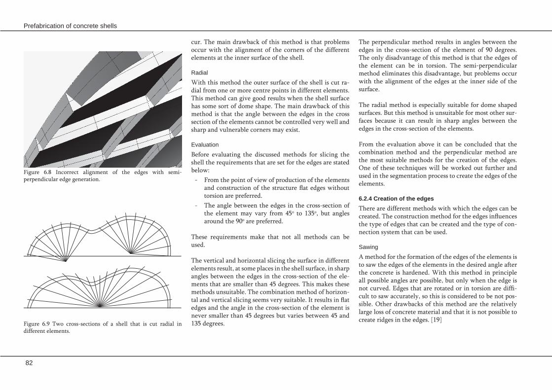
82
Prefabrication of concrete shells
The perpendicular method results in angles between the edges in the cross-section of the element of 90 degrees. The only disadvantage of this method is that the edges of the element can be in torsion. The semi-perpendicular method eliminates this disadvantage, but problems occur with the alignment of the edges at the inner side of the surface.
The radial method is especially suitable for dome shaped surfaces. But this method is unsuitable for most other sur-faces because it can result in sharp angles between the edges in the cross-section of the elements.
From the evaluation above it can be concluded that the combination method and the perpendicular method are the most suitable methods for the creation of the edges. One of these techniques will be worked out further and used in the segmentation process to create the edges of the elements.
6.2.4 Creation of the edgesThere are different methods with which the edges can be created. The construction method for the edges influences the type of edges that can be created and the type of con-nection system that can be used.
Sawing
A method for the formation of the edges of the elements is to saw the edges of the elements in the desired angle after the concrete is hardened. With this method in principle all possible angles are possible, but only when the edge is not curved. Edges that are rotated or in torsion are diffi-cult to saw accurately, so this is considered to be not pos-sible. Other drawbacks of this method are the relatively large loss of concrete material and that it is not possible to create ridges in the edges. [19]
cur. The main drawback of this method is that problems occur with the alignment of the corners of the different elements at the inner surface of the shell.
Radial
With this method the outer surface of the shell is cut ra-dial from one or more centre points in different elements. This method can give good results when the shell surface has some sort of dome shape. The main drawback of this method is that the angle between the edges in the cross section of the elements cannot be controlled very well and sharp and vulnerable corners may exist.
Evaluation
Before evaluating the discussed methods for slicing the shell the requirements that are set for the edges are stated below:
From the point of view of production of the elements -and construction of the structure flat edges without torsion are preferred.The angle between the edges in the cross-section of -the element may vary from 45o to 135o, but angles around the 90o are preferred.
These requirements make that not all methods can be used.
The vertical and horizontal slicing the surface in different elements result, at some places in the shell surface, in sharp angles between the edges in the cross-section of the ele-ments that are smaller than 45 degrees. This makes these methods unsuitable. The combination method of horizon-tal and vertical slicing seems very suitable. It results in flat edges and the angle in the cross-section of the element is never smaller than 45 degrees but varies between 45 and 135 degrees.Figure 6.9 Two cross-sections of a shell that is cut radial in
different elements.
Figure 6.8 Incorrect alignment of the edges with semi-perpendicular edge generation.

Edges and connections
83
Evaluation
Which of the above described methods is the most suit-able method for the creation of the edges depends on the design and segmentation of the shell and type of connec-tion system that will be used
With sawing only straight edges without any ridges can be created and it is only possible to produce straight edges. This make this technique less suitable for most connection systems and perpendicular slicing of the edges.
Contra moulding creates elements that perfectly fit onto each other, but a lot extra handling with the elements are needed to create the edges. Beside this there is always an-other technique needed to make the edges that can not be created with contra moulding. Insertion of a strip in the mould makes all different types of edges possible, there are no restriction on the possible angles, torsion or ridges in the edges.
The insertion of a strip in the mould is the most suitable technique in most cases and will be used for the produc-tion of the edges in the proceeding of this Master’s thesis. In some special projects it might be possible that one of the other technique is better. Before a technique is chosen the other possibilities should always be considered.
Contra-mouldingWith this method a previously cast element is used to pro-duce the following element. This principle was used for the construction of the elements of the Millau viaduct toll gates, see also Chapter 1 ‘Introduction’. An advantage of this method is that there is a perfect fit between the ele-ments, because they are cast next to each other. But this method does need a lot of extra handling with the ele-ments, because they have to be placed in the right position for the contra-moulding. When the elements are rectan-gular and have other elements on four sides, this technique requires a good organisation to keep the process going and cast all elements correctly. With this technique not all edges of an element can be created with contra-moulding. There are always some edges that have to be created with another technique, like sawing or inserting a strip.
Inserting a strip
A method for the formation of the edges of the elements is to insert an extra strip in the mould that forms the edges of the element. This strip can be made of different (flex-ible) materials. The edges can have any shape, ridges and torsion in the edge are no problem and all possible angles in the cross-section of the element are possible. The main disadvantage of this method is that some extra actions are needed to produce the strips and place them on the mould. [19]
Figure 6.10 The formation of an edge with the insertion of a strip in the pin-bed mould. [19]

84
Prefabrication of concrete shells
6.3 Connections6.3.1 Wet connection A wet connection is a connection where the two elements are placed next to each other at a certain distance. The seam between the elements can be reinforced with steel bars and is filled with mortar to connect the elements per-manently. The reinforcement is applied to strengthen the connection.
A benefit of a wet connection is that the elements do not have to fit perfectly. Some deficiencies in the size and the shape of the edge can be taken by the wet connection.This connection system gives a good strong connection that is can transfer, besides tension and compression forc-es, also bending moments and torsion. The load introduc-tion of the forces into the elements is equally spread over the edge of the elements. The final connection has a good durability and can resist extreme forces due to for example fire. The connection however is not especially suited for the use with UHPFRC elements.Disadvantages of a wet connection are the fact that it is labour and time intensive to place the extra reinforcement and the mortar in the seam between the elements. The placement of the mortar is also dependent on the weather, when it freezes or rains the mortar cannot be placed. After the mortar is placed it takes some time for the mortar is hardened and the strength of the connection has devel-oped.
6.3.2 Bolted connection With a bolted connection the elements are connected to each other by means of bolts. In the elements provisions have to be made to attach the bolts. This can be with spe-cial holes in the elements or with some steel provisions for the bolts that are inserted in the mould before casting.
Figure 6.11 The forces that act on the connection between the different elements.
The design of connections for precast concrete elements concerns both the structural requirements and the meth-od of construction. The main purpose of the structural connection is the transfer of forces between the differ-ent precast elements and to obtain structural interactions when the system is loaded. The ability of the connection to transfer the action forces is vital to the stability and load carrying capacity of the entire structure. The forces that have to be transferred are compression, tension and shear forces, bending and torsion.
Beside the structural requirements there are also some other aspect that have to be taken into account during the design of the connection. Many precast concrete connec-tion details are not vulnerable to fire and require no spe-cial treatment. Other connections, like bolted or welded connections, where weakening by fire would jeopardize the structure’s stability should be protected to give the same resistance as the structural frame. The need for movement in a structural system, due to for instance the concrete creep and shrinkage, temperature variations and support settlements should be considered. If the need for movement is not considered there will be a risk of damage to the connection zone.At the location of the connection often additional rein-forcing bars, plates and other inserts are required and little room is left for the concrete. The space needed for rein-forcement and the needed concrete cover have to be taken into account during the design of the connection.The connections should preferably behave in a ductile manner; this means that large plastic deformations take place before failure. Simplicity of the connection makes the chance of mistakes during construction smaller and will probably make the connection less expensive.
In the proceeding of this paragraph different types of con-nection methods will be described and evaluated.

Edges and connections
85
To install this type of connection the elements have to be fixed temporarily before the tension can be applied on the elements. This complicates the assembly of the ele-ments. When the tension is applied on the elements a very durable connection is made that is very suitable for the use with UHPFRC elements, due to the high compression strength of this type of concrete composites.
6.3.4 Welded connection When a steel provision is inserted in the mould before casting the elements can be welded together to form a per-manent connection.
A welded connection can be a very strong connection. When the inserts that are welded together are designed properly the load introductions can also be good and no peak stresses develop in the concrete. The fact that the insert are welded together makes that the adjustment pos-sibilities are small and the tolerances of the elements also have to be very small. It is very hard to make a good weld on the building site. So the assembly of the elements with a welded connection is difficult and not weather independent. The steel inserts that are welded together have to be protected against cor-rosion to make the connection durable. This type of con-nection is suitable for the use with UHPFRC.
6.3.5 Glued connection A recently developed connection system is the glued connection. In gluing technology the assembly parts are joined by the use of plastic or liquid adhesives that harden by chemical or physical processes. The strength of the ad-hesive joint is caused by two major forces, the adhesive and cohesive forces. In civil engineering epoxy resins are normally used to temporarily fix prefabricated concrete elements that are finally fastened with mechanical meas-ures. In this use the adhesive act more as a sealing and do not have to be capable bearing the constructional loading for the whole life service. Since UHPC is a very homo-
A bolted connection provides a high strength connection system that is easy and fast to assemble. The stiffness an capability of taking bending of a bolted connection de-pends on the design of the connection. The forces in the connection are introduced into the concrete locally, and if the connection is not designed properly too high peak forces may exist. If the connection is designed properly there are good ad-justment possibilities. Problems with this type of connec-tion are found in the price of the system, it is expensive to make this connection durable. The steel of the bolt is sensitive for corrosion and also a good fire protecting coat-ing has to be applied. The design of a bolted connection is very important it de-termines the strength, the load introduction, the ease of assembly and the durability of the connection. It can be difficult to design a good connection that can be used all over the shell surface, especially when the curvature and shape of the elements change over the surface.
6.3.3 Post-tensioning connection In a post-tensioning connection the elements are pro-vided with ducts trough which continuous tendons are placed. After the placement of all elements the continuous tendons are tensioned and fixed at the edges of the shell surface. To make sure the alignment of the elements is perfect, before the cables are tensioned, a temporary con-nection with epoxy resins can be made.
The post-tensioning connection with continuous cables does not only provide a strong connection between the element it also increases the tensile strength of the com-plete shell. The loads of the post-tensioning stress is in-troduced in the outer elements. This can give very high peaks stresses in the concrete around the anchor points of the tension cables.A drawback of this type of connection is that the elements need to have a minimal thickness, because the duct for the cable has to be placed in the elements.
Figure 6.12 Epoxy joint of a rough surface in detail; a) tensile load b) shear stress. [6]

86
Prefabrication of concrete shells
over a length of about 140 meter. In this bridge the precast UHPC deck plates are glued to the upper chords of the truss structure without any additional mechanical bond-ing devices. Before the application a series of tests was per-formed to test the strength and durability in all weather and climatic conditions of glued UHPC connections, made with an epoxy resin of Sika. The tensile strength of the tested prisms was between 6 and 7 N/mm2 and the flexural tensile strength between 10 and 13 N/mm2. [6] The speci-men failed within the concrete structure adjacent to the epoxy layer. Also some long-term stability tests were performed by fix-ing specimens in a frame under different thermal and cli-matic conditions for 56 days. The shear stress in the epoxy layer during these tests was 2 N/mm2. The strength of the specimen after 56 days was between 12 and 16 N/mm2. [6]The tests showed that the failure occurred in most cases in the concrete matrix.The testing program showed that there are still some ques-tions left and to make gluing a more often used method in the building industry and civil engineering some more testing has to be done.
6.3.6 Fibre jointsThe fibre joint is actually an alternative of the wet con-nection, where fibres are used in steads of reinforcing bars. The fibres used in UHPFRC are not suitable for use in the connection, due to their small dimension. Therefore fibres with a diameter of 0,7 mm, a length of approximately 60 mm and a hooked end are used. These fibres are inserted into a supporting ribbon that can also serve as a formwork for the edges of the elements (See Figure 6.15). This type of joint can transfer all forces on the connection, also forc-es oblique to the joint.
This type of joint is suggested by A. Lichtenfeld in [20]. In his paper he refers to some tests that have been performed to determine the load bearing capacity of the joint. For the tests on the construction joint specimens with a concrete
geneous material with respect to its mechanical proper-ties, the properties on the surface regions are the same as the properties of the bulk material, and has a high tensile strength it is suitable for gluing of the elements.
To obtain optimal results in the application of gluing tech-nology the surface properties of the parts are most im-portant. This means that the concrete surface has to be roughened and loose particles and other impurities have to be removed before the application of the epoxy resins to ensure a firm mechanical bonding of the adhesives to the UHPC surface. After the subsequent element is placed vibration can be used to make sure the target thickness of the joint is reached. The benefits of this type of connection is that it is easy applicable and that the shear and tension stresses can be transmitted very homogeneously. The ten-sile and bearing strength of the epoxy resin are practically identical with the tensile strength of the UHPC itself.
This type of connection is used for the first time in the Gartnerplatz Bridge in Kassel that spans the river Fulda
Figure 6.15 Supporting ribbon with fibres. [21]Figure 6.14 Cross-section ogf the Gartnerplatz bridge in Kassel. [6]
Figure 6.13 The Gartnerplatz bridge in Kassel. [6]

Edges and connections
87
The connection system must be able to be applied on -elements made of UHPFRC.The connections system should provide a fast, easy -and weather independent assembly of the elements.The connection system should have a good durabil- -ity.
The properties of the different connection systems, with respect to the different requirements stated above, are summarized in Table 6.1. This table show that all different connection systems have their advantages and disadvan-tages. There is not one connection system that can be con-sidered a the most optimal connection system. The choice for a connection system will always be a considering be-tween the advantages and disadvantages of each systems and also depends of the properties of the design.
On the basis of the properties of the connections the wet connection, glued connection and bolted connection will be used to develop a connection for the case study in the proceeding of this thesis.
height of 40 mm and a fibre content of 0,26% and 1,3% were used. The fibre overlap is 28 mm. The test results show that the applicable bond stress increases with a lower fibre content, this results from the reduced concrete dam-age due to a decrease in stress. The larger applicable bond stress coincides with a rather large deformation. Based on these first tests a required fibre content of 0,87% is derived, with an applicable bond stress of 8 N/mm2 and an overlap of 30 mm for UHPC with an axial tensile strength fct,ax of 12 N/mm2. On basis of these primary tests further testing has to be performed to further investigate the strength proper-ties and durability of the connection.
6.3.7 Evaluation Before the different types of connection systems are eval-uated the requirements for the connections are stated be-low:
The load bearing capacity of the connection may not -determine strength of the complete shell structure.At the place where the loads are introduced into the -element no very high peak forces may exist. The connection has to function in every occurring -situation.The connection system needs to have a possibility of -adjustment to the tolerances of the construction and the elements.
Figure 6.16 Test setup for the test with the fibre reinforced construction joint. [21]

88
Prefabrication of concrete shells
Wet connection Bolted connection Post-tensioning connection
Welded connection Glued connection Fibre joint
Connection strength Strong Strong, but stiffness and moment capacity difficult to ensure.
Strong and increased tensile capacity of the shell due to compression of the elements.
Strong Strong, but long term performance not completely known.
Strength and durability properties not completely known.
Load introduction The loads are introduced equally spread over the edge of the elements.
High peaks stresses can occur, but should be avoided with proper a design.
High peak forces in outer elements where tension tendons are anchored can occur.
No peak stresses in the concrete should occur.
The loads are introduced equally spread over the edge of the elements.
The loads are introduced equally spread over the edge of the elements.
Adjustment possibility Enough room for adjustment due to space between the elements.
Depending on the design, a good design has enough room for adjustment.
Not very large Small Not very large, but depends on the thickness of the layer of glue.
Sufficient
Suitable for use with UHPFRC
Not especially suitable, due to large difference in strength of mortar and concrete.
Suitable Very suitable, due to high compression strength of the concrete.
Suitable Very suitable, due to homogeneity of the concrete.
Very suitable
Ease of assembly It is labour intensive to place reinforcement and mortar, but the placement of the elements is easy.
When connection is designed properly the assembly is easy.
Complicated due to temporary fixing that is needed and the application of post-tensioning.
Difficult, due to welding on site.
Edges have to be roughened and cleaned carefully before the application of the epoxy layer.
Mortar should be placed in a relative narrow joint and the fibre may not bend during assembly.
Assembly speed Slow, mortar need time to harden and gain strength and the placement of the mortar is weather dependent.
Fast and weather independent assembly possible with a good design.
Slow, all elements have to be placed and fixed temporarily before tension can be applied.
When the weld is made the connection is strong, but careful preparation before welding is essential.
Slow, the edge have to be treated before the epoxy can be applied and the epoxy need some time to harden and gain strength.
Slow, mortar needs some time to harden and gain strength.
Durability Good Good, when protected properly against corrosion and fire.
Good Good, when protected properly against corrosion and fire
Still some research to long term performance needed.
Not known, research needed.
Table 6.1 Overview of the properties of the different connection systems.

Edges and connections
89
For some connection systems it is necessary that re- -inforcing bars or other inserts are placed in the ele-ments. For other systems it is not possible to place reinforcing bars in the concrete.
The choice for a connection system will always be a -consideration between the advantages and disadvan-tages of each systems and depends of the properties of the design.
On the basis of the properties of the connections the -wet connection, glued connection and bolted con-nection will be used to develop a connection for the case study in the proceeding of this thesis.
Edges
The two best methods to create the edges of the ele- -ments, for most surfaces, are the combination method and the perpendicular method.
The combination method combines both horizontal -and vertical slicing and results in flat edges of which the angle in the cross-section of the element is never smaller than 45 degrees but varies between 45 and 135 degrees.
The perpendicular method results in angles in the -cross-section of the element of 90 degrees. The only disadvantage of this method is that the edges of the element can be in torsion.
The most suitable technique for the creation of the -edges is the placement of a (flexible) strip on the mould that has the shape of the edges. With this method all different types of edges are possible, there are no restriction on the possible angles, torsion or ridges in the edges.
Connections
There are many different types of connection systems -that can be used to permanently connect the ele-ments to each other. The types of connection systems that are discussed in this theses are, the wet connec-tion, a bolted connection, a post-tensioning connec-tion, a welded connection, the glued connection and the fibre joint.
6.4 Conclusions

90
Prefabrication of concrete shells

7. Production and constructionIn this chapter the production of the prefabricated elements and the construction of the shell are considered.
Stored precast concrete elements. [2]

92
Prefabrication of concrete shells

Production and construction
93
The construction method will also give its restraints for example on the segmentation method and the connections between the elements. Of course the precise construction method is different for every design, but some general comments about the needed tolerances, scaffolding and lifting points can be given.
The production of the elements is discussed in paragraph 7.3. After this the transport of the elements is discussed in paragraph 7.3. The construction and the tolerances are discussed in respectively paragraph 7.4 and 7.5.
7.1 IntroductionWith the design of a prefabricated concrete shell different aspects have to be taken into account. This chapter dis-cusses the aspects of the design process that concern the production and construction of the shell structure.
The production of the elements takes place when the de-sign of the structure is completed. During the design the production of the elements is already considered, to take the restrictions from this process into account in the de-sign.
After the production of the elements they have to be transported to the site. This transport can be done with different means of transportation, boat, train or truck. But it is most likely that the elements will be transported by road. To this transport different restrictions on the size and weight of the elements are given.

94
Prefabrication of concrete shells
When the element is placed in the virtual mould, the loca-tions of the pins and the ejection length of each pin has to be defined. To determine the ejection length of the pins a grid, that represent the pins in the real formwork, is pro-jected on the surface of the element. After this the length of the line between the point on the surface and the cor-responding point on the bottom of the box can be deter-mined. This length is the ejection length of the pin. Both van Roosbroeck [19] and Rietbergen [41] made a program with which the height of the pins in the mould can be determined on the basis of a digital model of the elements.
Besides the height of the pins, also the place of the edges has to be determined with the help of the virtual mould. The outlines of the element can for example be printed on a large sheet of paper that can be placed on the adjust-able formwork to mark the places where the inserts for the edges can be placed.
The complete process of setting up the mould can be sum-marized as follows: 1. Extract an individual element.2. Place the element on the virtual mould. 3. Rotate the element to the right orientation.4. Project the grid of the mould on the element surface.5. Determine the ejection length of each pin.6. Determine the place of the edges of the element.7. Placement of the inserts and adjustment of the real mould.
7.2.2 Inserts for the edgesTo cast the elements inserts, that form the edges of the ele-ments, have to be made. The inserts can be placed on the mould before the mould is brought into the curved shape or after the mould is deformed.
7.2 ProductionIt is assumed that for the production of the elements a flexible pin bed mould will be used. This is an expensive mould and there will probably be only one mould avail-able for the production of the elements.
Because there is only one mould available the production process can only be shortened by speeding up the produc-tion of each individual element. This can be done by, fast demoulding after casting, fast adjustment of the mould for the next element and fast preparation of the mould for casting. With the preparation of the mould is meant the placement of the reinforcement and other inserts in the mould.
7.2.1 Virtual mouldTo set-up the mould the height of the pins in the mould has to be adjusted so that the shape of the element is formed. To determine the height of each pin an element is placed on a virtual mould. The virtual mould is a digital model of the adjustable formwork that is used to determine the set-tings of the real adjustable formwork.
The orientation in which the element is placed in the con-struction is in most cases not the most optimal orienta-tion for the production of the element in the adjustable mould. The best orientation of the element for produc-tion is when the pins are least ejected. This means that the orientation of the element must be as horizontal as possible and the element has to be rotated before it can be placed on the mould. To reach the desired orientation the element has to be rotated around two perpendicular axes. The line of rotation is a line that goes through the lowest points of the element in both directions. First the rotation in one direction is performed and then the second rota-tion line is placed and the rotation around the other axis is performed.
Figure 7.1 The rotation of an element around one axis to the right orientation for the placement on the adjustable formwork. After this rotation the elements has to be rotated around the other axis.

Production and construction
95
The second method can simplify the production of the inserts for the edges. This method is especially suitable when the edges are perpendicular to the surface. When the edge are flat or have an other orientation to the surface this method is less suitable. The first method is good for elements with flat edges and when the angle between the edge and the surface varies and is less suitable for edges in torsion.
7.2.3 Preparation of the mouldBefore the concrete can be cast the inserts which form the edges have to be placed on the mould. The provisions that might be needed for the transport of the elements and the connections between the elements also have to be placed on the mould. When necessary, the steel rein-forcement has to be placed on the mould before casting. If the element needs steel reinforcement the mould has to be brought into the curved shape before casting, because the reinforcing bars cannot be deformed by the mould after casting. It should be possible to place the reinforcement and inserts in the mould correctly orientated and within the necessary tolerances with a minimum amount of ef-fort. The more things, inserts, reinforcement etcetera, that have to be placed in the mould the longer it takes to pre-pare the mould for casting. It is desirable to repeat details as much possible, to make the preparation on the mould less complicated. When all inserts and the reinforcement have been placed on the mould the concrete can be poured into the mould to cast the element.
7.2.4 Casting processCasting concrete in a thin layer on the curved shell surface is difficult. When the concrete mix is too fluid the con-crete tends to sag and flow. The elements will be too thick in the lower parts and too thin in the upper parts of the mould. To prevent this the fibre reinforced concrete can be poured into the mould when the surface of the mould is still flat. The mould is brought to the deformed curved shape when the concrete is starting to get a little bit hard-
When the inserts are placed into the mould when the mould is already in the curved shape. The inserts should have the exact shape of the edges. This means that not only the applied ridges have to be formed, also the torsion of the edge has the be transferred to the edge.These inserts have to be made of a material that is easy to shape, like wood or expanded polystyrene foam (EPS). To form the inserts a multi-axial milling machine can be used. The computer model of the edges can be used to cut the insert in the right shape with a milling machine.
The inserts can also be placed on the mould before the mould is brought in the deformed shape. This means that the inserts should have enough deformation capacity to let it take the correct shape after deformation. The insert will rotate in line with the rotation of the mould. Only the rotation of one edge will probably not be the same all over the length of the edge so the insert must allow a varying rotation of the insert over the length of the insert. In other words it must be able to create an edge in torsion only by the rotation of the mould surface. This means that a flat edge that is mounted perpendicular on the mould surface is automatically is deformed to the right shape by the de-formation of the mould. This can make the production of the inserts for the edges easier, because no complicated inserts with edges in torsion have to be made with the use of milling machines. This types of inserts might also make re-used if the inserts possible.There might be some difficulties with the alignment of the two strips at the corners of the elements. To find out whether this gives real problems some tests have to be performed.The only task is to find the right type of insert that is strong but also has the flexibility of to deform into the right shape by rotation of the mould. The first idea is to make the in-serts of thin flexible strips that are mounted on the mould with a couple vertical strips that are placed perpendicular to the edge strip. These strips do also support the edge strip during the hardening of the concrete. (See Figure 7.2)
Figure 7.2 Design of the inserts that form the edges of the elements.
1
2
Concrete Edges
Adjustable pinsRubber cover layer
Figure 7.3 Casting principle of the adjustable mould. (1) The concrete is poured into the mould when it is still flat. (2) The deformation of the mould takes place when the concrete is partly hardened.

96
Prefabrication of concrete shells
transportation, by crane, to the storage pit. For transport by crane provisions for the attachment of crane hook have to be added to the mould before casting. It might be pos-sible to place the adjustable mould on a turning table, but this makes the mould more complicated and difficult to handle. Besides this the vertical transport of the elements makes that large transport loads are induced on the ele-ments.
Another idea that for demoulding the elements is to use a couple ties that are placed under the element before cast-ing to lift the element. The ties have to be placed under the rubber cover, that is placed on top of the pins, to keep the surface of the element smooth. For demoulding the ties are attached to a crane and the element can be care-fully lifted from the mould. The rubber cover is lifted with the element and can protect the element during storage. For this method no lifting provisions have to be inserted into the elements.
7.2.6 Storage of the elementsAfter production the elements have to be stored several times on different locations. The elements are demould-ed shortly after production, before they reach their final strength. At this time the type and place of the support of the elements during storage is very important. Wrong storage can cause cracks or unnecessary deformation.
The curvature of the elements makes it more difficult to store the elements. They cannot be stored in the same way as straight beams or flat floor elements, on top of each other separated with support blocks. It is suggested to use a special frame with six in height adjustable pins for the storage of the elements. On top of the pins a square sup-port block can be placed, to spread the weight of the ele-ment more equally. This support should be able to rotate freely around the top of the pin to get the optimal orien-tation for supporting the element. The pins can be simple screw pins, that can be adjusted in height manually. The
er. This method of casting prevents that elements with an undesired varying thickness are cast. A possible drawback of this method for casting the elements is that in the more curved areas some tension or compression stresses might be present due to deforming the partly hardened concrete. This might influence the stresses in the completed struc-ture.
Whether the mould will be deformed before or after pouring the concrete into the mould depends on the type of concrete that will be used for the elements. When a sprayed mortar is used it can be sprayed on the deformed mould without a large risk of sag or flow of the concrete. But when a more fluid concrete composite is used it might be better to bring the mould to the curved shape after cast-ing.
7.2.5 DemouldingBefore the elements are placed in their final position they have to be lifted several times. During these lifts special care has to be taken not to damage the elements. The first time the elements have to be lifted is with the demould-ing of the elements. At this moment the concrete does not have its full strength yet, and the elements are very sensi-tive for cracking and damage.
The lifting of the elements out of the mould of flat ele-ments can be done with a vacuum lifting machine. This is very suitable for vulnerable elements that are easily dam-aged. Another advantage is that, for this type of lifting, no lifting provisions are needed. The standard vacuum lift-ing machines are not suitable for lifting double curved el-ements. It might be possible to adapt these machines and make vacuum lifting for double curved elements possible, but this is probably very expensive.
For demoulding also a turning table can be used. On this table the mould is placed and it can turn the mould and the element in a vertical position for demoulding and
Figure 7.5 A flat element lifted by a vacuum lifting machine. [2]
Figure 7.4 Due to the deformation of the partly hardened concrete some tension or compression stresses may develop in the curved parts of the elements.

Production and construction
97
7.2.7 EvaluationTo speed up the production process the production of each individual element has to be as fast as possible. The pro-duction time of the elements is influenced by the set up time of the mould and the hardening time of the concrete. To make the preparation of the mould faster and easier it is preferred that no reinforcement is needed in the ele-ments.
A lot time can be saved when the same elements is used a couple times. In this case the shape of the mould does not need to be adjusted between the casting of two elements.
The storage of the elements on special frame is expensive, but eases the storage and transport of the elements and protects elements against damage.
frames can be made in such way that several elements can be stored on top of each other to save storage space.
The amount of frames that will be needed to store all ele-ments of a shell depends on the amount of elements in the shell. For a large shell many frames might be necessary, what makes the construction of the shell more expensive. But the size of the elements depends mainly on the size of the formwork. This means that the formwork also deter-mines the size of the frames and re-use of the frames for different shells is possible.
For transport the element have to be loaded on and of the truck. This can be done lifting each individual element with a crane. When the elements are stored on the frame, this frame can be used to place the element onto the truck. In this way the elements are exposed less to large trans-portation loads and are protected against damage during transport.
Figure 7.6 Precast concrete element on a turning table. [2]
Figure 7.7 Model of the frame to store the double curved elements.
Figure 7.8 Element transported with a crane in the factory. [2]

98
Prefabrication of concrete shells
For the weight of the vehicle, including the load, there are also limitations. The maximum load of a truck combina-tion is 50 ton. A truck weighs about 20 ton, so the maxi-mum the load on the truck is about 30 ton, The maximum load on one axle of the truck can be set on about 10 ton. More information about the regulations can be found on www.rdw.nl/tet.
When the elements are not produced on site, they have to be transported from the factory to the building site. De-pending on the facilities near the factory and near the site the elements can be transported by road, by rail or by wa-ter. Rail or water transport will not be used very often, be-cause in most cases not both the factory and the building site are close to a rail way or a large enough water way. These ways of transportation will only be used is very spe-cial cases. For the most materials transport by road is the most efficient way of transportation.
In the Netherlands there are restrictions on the sizes of the vehicle and the transported load. When these dimensions are exceeded a special transport licence is needed. These limitations are:
The maximum length of a single load is 12 meter. -The maximum width of the load is 3,0 meter. -The maximum height of the vehicle with the load is -4,0 meter.
When a low loader is used for the transport of the element, of which the platform has a height of about 1 meter, the maximum height of the load is approximately 3 meter.
7.3 Transport
Figure 7.9 Concrete elements on a low loader. [2]

Production and construction
99
Figure 7.10 Temporary scaffolding used during the construction of the canopy at sanatorium ‘Zonnestraal’.
To place the elements they are lifted by a crane and are carefully lowered into their final position. Before the ele-ments are disconnected from the crane support they have to be fastened and their stability has to be guaranteed. De-pending on the type of connection system that is used the elements are fastened permanently directly after placing or first with a temporary connection. In this case the final connection will be made after more elements are placed or it takes more time for the connection to gain enough strength to secure the element. This is for example the case with a wet connection, while a bolted connection can be made while the element is still supported by the crane.
When all elements are placed and the connection are made the temporary supports can be removed and the construc-tion can be finished.
When the elements are produced at the same time the work on the building site can start. Before the elements can be placed the work on the foundation or construction on which the shell is going to be placed has to be finished. Beside this probably also some scaffolding or other type of temporary supports for the elements have to be placed. When the site is prepared for the placement of the ele-ments they will be transported to the building site and the construction of the shell can start.
The construction sequence of the shell is already deter-mined during the design process. The loads that are in-duced on the elements during construction are often larger than the service loads on shell. Designing the connections and the elements these extra loads have to be taken into account and special measures have to be taken to prevent damage due to these loads. This can be done by strength-ening the connection or the elements and by placing tem-porary supports.The stability of the shell and the individual elements should be guaranteed at any moment during construction. To do this scaffolding will be necessary.
With the design of the connections the placing move-ments should be taken into account to prevent connection details that makes placement of elements impossible. The torsion in the edges makes the placement of the elements more difficult and makes that a larger adjustment area is needed to place the elements.
7.4 Construction

100
Prefabrication of concrete shells
The size and shape of the mould and the elements cast with it is never absolutely perfect, therefore there are al-ways some deviations in the shape of the elements. The tolerances can be defined as the maximum allowable de-viation in the size and shape of the elements and the con-struction. Deviations have basically two reasons. The first are inaccuracies caused by humans and the second physi-cal reasons. The total deviation of a prefabricated structure is the result of the following part deviations.
Product deviation
Product deviations are for example deviations in the size of the elements and temperature expansion. The size and shape of the mould is never absolutely perfect, therefore there are always some deviations in the size of the ele-ments. Due to the change in temperature the size of the concrete elements varies. To prevent cracking of the concrete the concrete must have space to expand and expansion joints have to be placed in the structure.
Erection deviation
For the assembly or connection of the elements some extra tolerances may be needed. There must be some space for handling and placement of the elements.
Deviation of the work done at the site
The work done at the site is commonly not performed as exact according to the plan as in the prefabrication con-crete technology.
All these possible deviations have to be taken into account during the design of the structure. If this is not done cor-rectly there is the risk on damage or delay during con-struction.
The reasons for the total deviation are the same for any structure where units are produced off site, regardless of the material. However, when something is not quite right concrete is a little more difficult to alter or adjust com-pared to for instance steel or wood. Therefore one has to pay more attention to tolerances in prefabricated concrete structures and to develop connection details that have the necessary room for adjustment. A connection should al-ways be as adjustable as possible. Preferably the connec-tion detail should be adjustable in three directions. This may be difficult to combine with a requirement for sim-plicity.
7.5 Tolerances

Production and construction
101
During the construction of the shell the stability of -the shell had to be ensured at all time. To do this tem-porary scaffolding and careful planning of the con-struction is necessary.
The elements are placed in the construction with the -help of cranes. To make lifting of the elements with a crane possible, lifting provisions, like hooks, have to be attached to the elements. The lifting of the ele-ments on these hooks might induce forces into the elements that are much larger than the standard de-sign load. These loads have to be taken into account during the design of the shell.
There are different types of deviations present in a -structure that can be divided in product deviations and erection deviations. The maximum allowable de-viations are defined by the tolerances of the struc-ture.
For the production of the elements they have to be -placed on the mould in the orientation of the element in which the pins of the mould are least ejected. To reach this orientation the elements have to be rotat-ed.
There are different types of inserts that can be used -to form the edges of the elements. The shape of the inserts depends on the form of the edges and wheth-er they are placed on the mould before or after the mould is brought into the deformed shape.
To make the production of the elements easier and -faster no steel reinforcing bars should be applied in the elements.
Storage of the double curved elements is more dif- -ficult than storage of straight prefabricated concrete elements. For the storage special frames can be used that can also reduce the induced loads on the ele-ments during lifting and transport.
The element can best be transported by road. This -makes that the maximum elements size and weight are limited. The maximum length of a load is 12 me-ter and the maximum width is 3 meter. The maxi-mum weight of the transport loads is about 30 ton.
7.6 Conclusions

102
Prefabrication of concrete shells

8. Design processIn this chapter the different aspects of the building process will be outlined and the relations between these aspects will be discussed.
Architectural design
Structural analysis
Segmentation and element
generation
Production and Construction
Optimization ofThe segmentation
Optimization of the designOptimization of
The design
Final Design

104
Prefabrication of concrete shells

Design process
105
segmentation are treated at the same time. To make the analysis of the design process a little less complicated only the shell structure is considered, even though it might be a part of a larger structure. All other parts of the structure, like for example the foundation, the cladding or the inte-rior design, are left out of consideration.
In paragraph 8.2 the different aspects of the design proc-ess are introduced. After this the relations between these aspect are given in paragraph 8.3, and in paragraph 8.4 the complete design process is analysed.
8.1 IntroductionAfter analysis of the different aspects of the design, pro-duction and construction of prefabricated concrete shells in this chapter the relations between these aspects and the design process of these shells will be analysed.
In the complete building process of prefabricated concrete shells three different phases can be distinguished, the de-sign, the production and the construction. In the design phase the complete design for the shell is made. In the sec-ond phase, the production, the elements are produced. In the last phase, the construction, the shell is build. In this chapter only the design process is discussed, because this is the most complicated phase of the building process.
The design of prefabricated shell structures is very com-plex. The process has the be performed as an integral process, where the design, the structural analysis and the
Design
Building process
Construction
Production
Figure 8.1 The complete building process can be divided in three parts, the design, the production and the construction of the shell.

106
Prefabrication of concrete shells
The formwork gives the choice for the mould with which the elements will be made and the restrictions this mould gives for the shape and production of the elements.
The concrete composition gives the choice for the mate-rial of which the elements will be made and the properties of this material.
The connection system determines how the edges are made and the properties of the connection system that will be used to connect the elements to each other.
The element size, shape and curvature give the restric-tions or choices for the size, shape and curvature of the el-ements. The choice for the element requirements is made mainly on the basis of other choices that have been made for example for the transportation method and the type of formwork that will be used.
Beside the aspects that are discussed in this paragraph a lot more aspects, that influence the design process can be determined. With the aspects discussed here it is tried to find the most important aspects concerning the structure of the shell. All other aspects are left without consider-ation. With these aspects it should be possible to give a pretty complete overview of the design process of the shell structure that at the same time will not be too complex.
The aspects that have to be taken into account during the design of a prefabricated concrete shell will be called the design aspects. The different design aspect that are distin-guished here are:
Architectural design -Segmentation and element generation process -Structural analysis -Production and construction -Formwork -Concrete composition -Connection system -Element size, shape and curvature -
The architectural design is the design for the building made by the architect. This design is in most cases the starting point of the design process.
The segmentation and element generation process is the process in which the shell is divided into the different ele-ments. This process generates a grid over the shell surface, defines the edges of the elements and can isolate the indi-vidual elements of the shell.
During the structural analysis the strength, stiffness and stability of the designed shell are determined and control-led according to the valid building codes. The stresses and deflections of the shell have to be within the requirements for all load cases.
In the aspect production and construction the production and construction process of the shell are determined. Here for example the production sequence of the elements, the building sequence and the placement of the scaffolding are determined.
8.2 Design aspects

Design process
107
Figure 8.2 The relationship scheme of the relations between the different aspects of the design process.
2. Relation architectural design & structural analysis
The architectural design will be used to perform the struc-tural analysis of the shell design. On the basis of the results of this analysis the shape of the surface may be changed, to get a more optimal force transfer in the shell.
3. Relation structural analysis & segmentation and element generation process
With the structural analysis of the shell surface the place of the edges of the elements has to be taken into account. The strength of the connections is probably not the same as the element strength so the place of the edges might in-fluence the structural behaviour of the shell.
The different aspects of the design process influence each other in different ways. For the aspects defined in the pre-vious paragraph the relations between them are given in Figure 8.2. These relations are defined with the help of the relationship scheme defined by Van Roosbroek [19]. The relations that are determined here are not exactly the same relations as Van Roosbroeck defined. The relations given in the scheme are explained below.
1. Relation architectural design & segmentation and element generation process
The architectural design will be used to segment the shell surface and generate the elements. When the segmenta-tion has been analysed the architectural design might be changed to make a more optimal segmentation of the shell possible.
8.3 Relations between the aspects
Architectural design
Concrete composite
Connection system
Production and Construction
Element shape, size
and curvature
Formwork7
8
14
11
9
13
Structural analysis
6
12
10
Segmentation and element
generation 5
3
4
2
1

108
Prefabrication of concrete shells
8. Relation formwork & element size, shape and curvature
The elements will be produced in the flexible pin-bed mould. The size of the mould gives restrictions to the max-imum size of the elements. The formwork does also give restrictions for the maximum curvature of the elements.
9. Relation concrete composite & production and construc-tion
The type of concrete composite that will be used for the elements influences the production of the elements. Each concrete composite has its own casting method and hard-ening time. These properties influence the time needed for casting and hardening of the concrete. The construction of the shell is also influenced by the concrete composite. The strength of the elements influence the type of scaffolding and lifting method that will be used for placing the ele-ments.
10. Relation structural analysis & production and construc-tion
The forces that are imposed on the elements and the struc-ture during the construction of the shell are often larger than the service loads on the structure. So the construc-tion of the shell has to be carefully planned taking into account the construction forces. These forces also have to be taken into account during the structural analysis of the shell.
11. Relation production and construction & formwork
The type of formwork that will be used influences the pro-duction of the elements. On the basis of the type of form-work the time that will be needed to set up the mould in the right shape between the casting of two elements can be determined.
4. Relation segmentation and element generation process & production and construction
The segmentation and the shape of the elements influence the production of the elements and the construction of the structure. When the generated elements cannot be pro-duced or give problems with the construction of the shell the segmentation or the shape of the elements has to be improved.
5. Relation segmentation and element generation process & element size, shape and curvature
During the segmentation of the surface the requirements for the size, shape and curvature of the elements have to be taken into account. When the generated elements do not fulfil the requirements for the elements size, shape and curvature the segmentation has to be improved until all element fulfil the requirements.
6. Relation structural analysis & concrete composite
The strength properties of the concrete composition influ-ence the structural analysis of the shell. The thickness of the shell and the needed reinforcement in the elements are determined by the interaction between the concrete composition and the shell analysis. With the strength properties of the concrete and the determined forces in the shell the thickness of the shell and the possible needed reinforcement in the elements can be calculated.
7. Relation concrete composite & formwork
The type of concrete composition influences the produc-tion of the elements. Different concrete compositions may require different casting methods. The type of formwork that will be used therefore influences the choice of the type of concrete composite.

Design process
109
12. Relation structural analysis & connection system
The type of connection system that will be used influences the force transfer in the shell. The strength and stiffness of the connection has to be determined while taking the forces in the shell into consideration.
13. Relation production and construction & connection sys-tem
On the basis of the chosen connection system the assembly process of the elements can be determined. The connec-tion system determines how the elements should be placed and how the connection should be made. Depending on the type of connection the speed of construction and the place and amount of scaffolding can be determined.
The production method is also influenced by the connec-tion system. The needed tolerances can be determined on the basis of the connection system. The production meth-od and production speed are influenced by the amount of inserts for the connection that have to be placed into the mould and the effort it takes to place these inserts cor-rectly.
14. Relation connection system & formwork
The type of formwork and the method with which the edges are created influences the design and choice of the connection system. The shape of the edges that can be made and the type of inserts that can be used influence the design of the connections.

110
Prefabrication of concrete shells
8.4 The design processpossible segmentation methods that can be used for this type of surface, not all surfaces can be segmented with every grid generation method. The architectural design and the segmentation of the shell will be used for the structural analysis. On the basis of the results of this anal-ysis the shape will be changed in order to get an improved force transfer and segmentation. The most optimal shape is a real shell structure, without any bending in the shell.
8.4.2 Structural analysisFor the structural analysis of the shell a finite element analysis program will be used. With this program the forc-es in the shell and the deflections of the shell can be cal-culated. To perform these calculations more information about the structure than only the shape and the segmenta-tion is needed. The additional information that has to be known to perform a structural analysis is:
The loads that act on the structure -The construction material -The type of connections between the elements -The connection of the shell with the foundation or -supporting structure
The loads on the structure can be defined using the regula-tions of the country in which the structure will be build.
The construction material is prefabricated concrete. The concrete composite that will be used can vary, but it is as-sumed that some sort of fibre reinforced concrete will be used. The strength properties and the regulations that have to be used for the calculation are different for the differ-ent concrete composites. When (ultra) high performance concrete is used an extra difficulty arises, because for these types of concrete still almost no regulations are made.
Architectural design
Structural analysis
Segmentation and element
generation
Production and Construction
Optimization ofThe segmentation
Optimization of the designOptimization of
The design
Final Design
Figure 8.3 The simplified design process of a prefabricated concrete shell structure.
In figure 8.3 the integral design process for the design of prefabricated concrete shells is shown in a very simpli-fied scheme. With the term integral it is meant that the design aspects of the design process are considered at the same time and not separately after each other. This proc-ess is determined based on the scheme with the relations between the different aspects shown in the previous para-graph. In this simplified scheme of the design process, the design choices, like the concrete composite, formwork and connection system, are not shown. The results of the different design aspects are used to improve the other as-pects of the process in different optimization routines. The result of this process is a design for the shell structure in which all aspects are taken into account and are improved as much as possible.
The architectural design can be seen as the starting point in this design process. On the basis of this design the first calculations and the first segmentation are made. The re-sults of these first calculations and segmentation can be used to modify and improve the shape of the shell. Be-tween the segmentation and element generation process and the structural analysis of the shell a continuous inter-action takes place improving both processes. On the basis of the generated elements the production and construc-tion process will be designed. This process will be used to optimise the generated elements and improve the struc-tural analysis of the shell. This process of design, calcula-tion and optimization will be repeated until the required optimization level is reached.
8.4.1 Architectural design The architectural design is made on the basis of the re-quirements for the building and a design idea or concept of the architect. On the basis of the architectural design a concept for the segmentation will be made. This can be either on the basis of the architectural concept or on the
Figure 8.4 Relations of the architectural design with other aspects of the design-process

Design process
111
with high shell forces, because in general the joints are the weakest link of the shell structure.
With the results of the structural analysis some shell prop-erties like the shell thickness and needed reinforcement can be calculated.
8.4.3 Segmentation and element generation processOn the basis of the architectural design the shell surface will be segmented. The segmentation process starts with the generation of a grid over de shell surface of the de-sign. This grid defines the size, shape and arrangement of the elements. This grid will be used during the structural analysis of the shell to determine the positions of the con-nections.
When the grid is generated the grid lines are used to gen-erate the elements. For each element the thickness and needed reinforcement is determined on the basis of the shell properties that are defined in the structural analysis. If the thickness and the shape of an element are known
The connections between the different elements influence the force transfer in the shell and the stability of the shell. How the forces in the shell are influenced depends on the type of connection system and the stiffness and strength of the connection.
The foundation or the supporting structure of the shell de-termines the edge conditions of the shell and influences the forces in the edges of the shell.
The results of the structural analysis is an overview over the stresses and deflections of the shell. This information can be used to improve the shape and segmentation of the shell. If for example the deflection in a certain part of the shell is relatively large it can be tried to give this part a larger curvature to reduce the deflections in this part of the shell. The curvature of the shell can also be changed to reduce the bending moments in the shell and improve the membrane action of the shell. The segmentation can be improved, after the structural analysis has been per-formed, by placing the grid lines not in parts of the shell
Segmentation and element
generationConcretecomposite
Connectionsystem
Shell forces, deflections and
properties
Foundation/support structure
Loads
Architecturaldesign
Optimization of the design
Optimization of the design
Structural analysis
Production and Construction
Figure 8.5 Relations of the structural analysis with the other aspects of the design-process.

112
Prefabrication of concrete shells
Shell properties
The thickness of the shell and the needed reinforce- -ment is defined in the structural analysis.
When the segmentation process is complete the different elements of the shell surface have been defined. The gen-erated elements are checked by the given requirements for the elements. These requirement can differ for each structure, here the following requirements are defined:
Shape of the elements -Element size -Element curvature -Shape of the edges -Thickness of the elements -Concrete cover -Tolerances -
When not all elements are designed according to the re-quirements and the desired optimization is not jet reached the segmentation and the architectural design of the shell have to be improved. When all aspects have reached the required optimization level the design can be considered as be complete.
8.4.4 Production and construction processThe production and construction of the shell are planned on the basis of the generated elements. The generated ele-ments are already controlled during the segmentation and element generation process. So the production of the ele-ment in the chosen formwork should be possible. Here the production order of the elements in determined.
During the construction of the shell forces are induced on the elements that are often larger than the service loads. These construction loads have to be taken into account during the structural analysis of the shell carefully. The construction of the shell should be planned is such way
the edges can be generated. With the design of the edges the type of connection system, the production of the el-ements and the construction of the shell are taken into account. In the segmentation process the edges of the ele-ments are generated according to this design.
During the segmentation process the following properties of the elements, the grid, the formwork and the shell have to be taken into account:
Elements properties
The shape of the edges of the elements should be -compliant with the connection system, the produc-tion method of the elements and the construction of the shell. The angle between the edges in the plane and the an- -gle between the edges in the cross-section of the ele-ments may vary from 450 to 1350, but angles around the 900 are preferred.A minimum size of the elements has to be defined to -prevent that the elements become too small and there will be too much elements, this slows down the pro-duction and construction process of the shell.
Grid properties
The grid should consist of double curved elements. -The elements should all have about the same size. -
Formwork properties
The maximum curvature of each individual element -is limited by the curvature that can be achieved with the formwork.The maximum size of the elements is restricted by the -size of the formwork.The design of the edges should be is such way that -they can be made with the flexible formwork and the chosen technique to create the edges.
Figure 8.6 The different actions in the segmentation and element generation process.
Architectural design
Control op the element properties
Generate the edges
Grid generation
Isolate individual elements
Shell properties
Element properties
Grid properties
Formwork properties
Define element thickness and reinforcement
Divide the surface into elements
Optimization of the segmentation and
element generation
Elements

Design process
113
Optimization the design for the segmentation
It might also be necessary to optimize the designed sur-face from the perspective of the segmentation of the shell. Not all surfaces are suitable for the generation of a grid of which the element are equally sized and not to skewed and twisted. When this is the case the surface has to be adapted to make the generation of a more optimal grid possible.
Optimization of the segmentation for the production and con-struction
The generated elements might not always be the most op-timal elements for production and construction. When this is the case the segmentation has to be adapted. The aspects that have to be optimized in most cases are the ele-ment size, shape and curvature or the shape of the edges of the elements.
For optimization in the building industry there is most of the time not one solution that is the most optimal in all cases. This makes it even more difficult to automate the optimization processes.
that the forces in the element and the partly finished structure do not become too large and that the stability of the shell is ensured at all time. To ensure the stability of the shell the use of scaffolding might be necessary.
The shape of the element must be such that all element can be placed in the right position easily. When this is not the case the shape of the elements has to be adapted.
8.4.5 OptimizationIn the design process different optimization loops can be seen. Optimizing the shell surface and the segmentation sounds simple but this is rather complex process.
Structural optimization of the design
Structural optimization is the optimization of the struc-tural behaviour of the design for all load cases. In the case of a shell structure the most optimal structural behaviour is a pure membrane stress in compression for all load cases. This process of optimization is very complex because in most cases the most optimal shape is not obvious and there is a large amount of criteria that has to be taken into ac-count.
In order to automate the optimization of the shell with the use of computers well defined parameters have to be defined that can be optimized. The definition of these pa-rameters is not easy. The last years many computational optimization algorithms have been developed. The opti-mization of the shell can be performed with computation-al optimization algorithms, but thorough control of the found solutions is still essential.
Figure 8.8 The relations of the production and construction process with the other aspects of the design process.
Structural analysis
Segmentation and element
generation
Production and Construction
Optimization ofThe segmentation
Final Design
Concrete composite
Connection system
Figure 8.7 Relations of the segmentation and element generation process with the other aspects of the design-process.

114
Prefabrication of concrete shells
8.5 ConclusionsThe goal of performing the process from the initial -architectural design to the final design as an integral process is to achieve a maximal optimization of the design with the minimum amount of effort.
The complete design process can not be automated -completely, there will always be some ‘human’ inter-action needed.
The automation of some parts of the design process -can ease the design of complicated structures, but thorough control of the found solutions will always be necessary.
For optimization in the building industry there is -most of the time not one solution that is the most op-timal in all cases. This makes it even more difficult to automate the optimization processes.

9. Geometry design toolIn this chapter the segmentation and elements generation process is discussed. The development of the design tool that can be used to generated the elements is based on this process.
A part of a shell that has been divided into different elements

116
Prefabrication of concrete shells

Geometry design tool
117
On the basis of the grid the surface can be divided in dif-ferent parts, which will form the elements. After dividing the surface the elements will be given a thickness and the shape of the edges will be defined. The process with which this will be done is described in paragraph 9.3.
Paragraph 9.4 deals with the control of the elements. Af-ter generating all elements it has to be controlled whether they fulfil the requirements that are set for the elements. In this paragraph the elements are controlled only on geo-metrical constraints.
In paragraph 9.5 the designed segmentation tool will be discussed and evaluated. The segmentation tool consists of three different parts; the grid generation, the generation of the elements and the control of the elements.
In this chapter the different aspects of the segmentation and element generation process will be discussed. This process considers the whole process from generating a grid on the surface to the detailing of the individual elements and checking the elements by the given requirements. First the different parts of the process that can be isolated are discussed and after this the design tool that has been developed is described.
Rhinoceros 4.0 will be used as the application with which the surface will de designed and segmented. The design tool has been written using Rhinoscript that is based on Visual Basic scripting.
In paragraph 9.2 the generation of the grid is discussed. As outlined in Chapter 3 there are a lot different meth-ods with which a grid can be generated. All these meth-ods have their own advantages and disadvantages. In Chapter 3 no final choice is made for the grid genera-tion method that will be used for the segmentation proc-ess. Here a couple methods will be outlined and developed further for the use in the segmentation tool. After this a final choice for the segmentation method can be made. Beside these methods there are many other methods, that might give better results for the segmentation of surfaces, but these methods were not available during this thesis.
9.1 Introduction

118
Prefabrication of concrete shells
9.2 Grid generationpreferred that there is not too much variation in the ele-ment size. As a result the element size needs to be con-trolled during the grid generation. In most grid generation techniques the element size can be controlled reasonably during the generation of the grid. After the generation of the grid the size of the elements has to be controlled to determine whether the size of the elements is within the set requirements.
For the production of the elements and the construction of the shell it is better that the elements are not too skewed or twisted and elements with low deformity and increas-ing uniformity are preferred. From the point of view of production the variation of the angle in the plane of the elements may for example vary from 45o to 135o degrees but angle of about 90o are preferred. Some grid genera-tion techniques generate elements that are pretty equally shaped, but others generate elements with a large varia-tion in shape. Therefore the shape of all elements has to be checked and optimized when necessary after the grid had been generated.
The surface should be divided in double curved elements and the grid generation technique should therefore gener-ate double curved elements instead of approximating the surface with flat elements. The use of the flexible form-work gives some constraints to the curvature of the ele-ments. With this mould it is not possible to create elements with a larger curvature than the maximum curvature of the mould. The grid generation technique should there-fore create elements with a curvature that is smaller than the maximal allowable curvature. The minimum radius of curvature of the used mould is set on one meter. Most grid generation techniques can not generate elements with a certain maximal curvature, in this case the curva-ture of each elements has to be checked after the grid has been generated. When not all elements are curved within
9.2.1 RequirementsThere are different requirements which the grid genera-tion technique has to fulfil. These requirements ideally will be used as input for the grid generation method. If this is done this will directly result in an ideal grid where all requirements are met. For most grid generation meth-od this will not be the case. Some requirement will be used as input, but others will be used to evaluate the quality of the grid and determine at which points the grid has to be optimized.
General
At first there are some general requirements, which con-sider the representation of the grid and the types of sur-faces that can be described with the grid.
The grid generation method has to be able to describe ir-regular, double curved surfaces and define the geometry in a digital model. The data, of the generated grid, stored in the digital model should be interpretable by software used in later stages of the design process. For the representation of the surface NURBS are used.
All the grid generation techniques that are described in this chapter can generate a grid over an irregular double curved surface. The data of the grid generation method can all be stored in a digital model. Whether this data can be used easily by other software depends on how the data is stored in the digital model.
Element shape and size
Secondly there are also some requirements that are con-cerned with the shape and size of the elements.
The transport of the elements from the factory to the site and the size of the formwork limit the size of the ele-ments. Beside the maximum size of the elements it is also

Geometry design tool
119119
Figure 9.1 A rapid variation in the height of the surface results in a variation in the element size.
The different grid generation methods are all tested on three different surfaces. The resulting grids of all three surfaces can be seen in Appendix 3.
Projection
This technique is based on the isotope technique and con-sists of the projection of a flat grid onto the surface that has to be segmented. Every flat grid can be projected onto a surface, but here only a grid composed of equally sized squares or rectangles is concerned. The grids generated with this method are structured and the size of the ele-ments is reasonably controllable by changing the cell size of the projected grid. A drawback is that when the free formed surface changes in height rapidly there can be a large variation in element size (See Figure 9.1). Another drawback of this method is that the elements at the edges of the surface can be small and badly shaped.
For the generation of a projected grid a simple script has been written that is based on the following steps:
Define the needed variables. -Ask the user the required length and width of the -grid.Ask the user the number of tiles in both directions. -Create the grid on the ground plane -Ask the user to define the surface on which the grid -has to be projectedProject the grid on the surface. -Delete the original grid. -
The developed script does not work optimal jet, but gives a good idea of the advantages and disadvantages of the pro-jection of a grid on a surface. To improve the script the size of the initial grid has to be based on the size of the surface, while this grid is now based on the size the user gives. It is also better when the user can give the required size of the cells in the initial grid in stead of the number of cells.
the limits the gird or the shape of the surface have to be changed until all elements are curved according to the re-quirements.
9.2.2 ApproachThere are three different methods with which the grid generation over the surface can be approached. In the first method a grid, that is probably not an optimal grid, will be generated over the surface. After the generation of the grid this grid will be optimized in a couple optimization loops in order to get an improved grid, which fulfils the given requirements. With the second method an optimal grid is generated over the surface that just need little im-provements after is has been generated. In the last method the surface is approached by an optimal grid that does not need optimization afterwards. This means that there will always be some deviation between the original surface and the generated grid.
These methods all have their own advantages and disad-vantages. A less optimal grid can be generated rapidly, while improving this grid takes a lot of time. Generating a more optimal grid is more complicated and takes longer, but when this grid has been generated almost no time is needed to improve it. When the grid is approached with an optimal grid it will take some time to analyse with which grid the surface is approached best and the devia-tion between the surface and the grid is minimized.
9.2.3 Grid generation techniquesThere are different grid generation techniques that can be used for the generation of the grid. On the basis of the evaluation in Chapter 3 four different grid generation techniques are chosen that are available, can be interpret-ed easily in practice and from which good result are ex-pected. It is possible to find better methods than the ones used in this thesis, but those were not available and could therefore not be used during this thesis.

120
Prefabrication of concrete shells
approaches the NURBS surface. The accuracy of this mesh depends on the mesh settings, like ‘minimum edge length’, ‘maximum edge length’ and ‘maximum distance, edge to surface’. More detailed information about these mesh set-tings can be found in Appendix 4. These detailed render mesh options control the way in which the NURBS sur-face converts to the polygon mesh.
The fact that a polygon mesh is created means that the sur-face is covered with a mesh that has elements with straight edges. To create the desired double curved elements the mesh is projected onto the surface. In this way the grid is placed on the surface an the double curved elements can be generated from the grid.
To generate the grid on the surface the following proce-dure is used:
Use the rhino command ‘_Mesh’ to generate a mesh -on the surface Use the script to extract the mesh wires -Project the wires on the surface -
Figure 9.4 The option control box that is used to control the settings for the mesh generation in Rhino.
These are some comments on the script as it is used here that have to be improved when this grid will be used for the final segmentation tool.
In the Figures 9.2 and 9.3 the script is used to generate a projected grid on two different surfaces. In the different figures it can be seen that the generated script is struc-tured and the elements are equally sized when the sur-face deviation in height is not to large. When the height of the surface varies rapidly some very large elements are generated. On the edges of the surfaces some small bad shaped elements are generated. These elements have to be improved before the grid can be considered as a good grid. It might be possible to improve the generated grid, and make the elements more equally in size, by making the projected grid more dense in rapidly in height varying ar-eas of the surface.
Rhino mesh
To generate this grid the Rhino command ‘_Mesh’ was used. The result of this command is a polygon mesh that
Figure 9.2 Surface of revolution with a projected grid.
Figure 9.3 Surface 2 with a projected grid. Figure 9.5 Surface 2 meshed with the Rhino meshing tool.

Geometry design tool
121
In Rhino the command ‘Extract.isocurve’ can be used to find and isolate the isocurves of a surface.
To generate this grid on the surface the following proce-dure is used:
Define the surface on which the grid has to be gener- -ated. Define number of elements in both direction. -Extract the isocurves in the u direction. - Extract the isocurves in the v direction. -
This method generates a structured grid over the surface. Whether this grid generation method generates a grid with equally sized elements depends on the placement of the isocurves over the surface. When the isocurves are not equally divided over the surface the size of the element can vary a lot over the surface. The place of the isocurve can be influenced by ‘rebuilding’ the surface. The rebuild command can be used in Rhino to reconstruct a surface to a specified degree and a specified number of control
This grid generation method can be used to segment every surface. The quality of the resulting grid can be adapted by changing the mesh settings. This results in a grid of which most elements are quadrangular and equally sized. The generated grid is however not optimal for every sur-face. For some surfaces the parts that have larger or more difficult curvatures are meshed with triangular or smaller elements.Another problem rises with the projection of the grid on the surface. This projection does not give a satisfying re-sult for all surfaces. For some surface the projected grid line doe not form a smooth grid over the surface, see Fig-ure 9.5.
Isocurve grid
This type of grid uses the isocurves of the surface to create the edges of the elements. An isocurve is a curved line that runs along the surface in the U and V direction of the sur-face. Each surface is made of NURBS curves is composed of isocurves.
Figure 9.6 Surface of revolution meshed with the Rhino meshing tool.
Figure 9.7 An isocurve grid generated over surface 1 before rebuilding the surface (left) and after rebuilding the surface (right). The maximum length of the edges is in both grids the same.

122
Prefabrication of concrete shells
These size of the elements can be controlled pretty well for most surfaces. The elements generated by the Rhino mesh tool approach the original surface with elements that have straight edges. The grid has to be projected onto the surface to get the desired grid. The only problem with pro-jecting the grid lines is that they do not follow the surface nicely, but can have a kink at the edge of the elements.
The isocurve grid generates a structured grid that is based on the isocurves of the surface. This means that the qual-ity of the grid depends on the placement of the isocurves over the surface. The placement of these isocurves can be improved by ‘rebuilding’ the surface. The element size and elements shape can vary a lot over the surface, but this can be improved by rebuilding the surface.
The translational grid is a structured grid that generates equally sized elements. The size of the elements can be controlled very well by varying the distance between the generator and the directrix. The shape of the elements varies a bit over the surface, but in general the elements are never to skewed and twisted. A large drawback it that this type of grid can only be used for the generation of a grid over translational surfaces.
The isocurve grid will be used for the development of the design tool. This grid is chosen, because it is an easy to implement method that generates a structured grid with reasonable equally sized elements that are not too skewed and twisted. The only major drawback of this grid is that is does not give a good grid for every surface. But there is no grid generation method available that is capable of gener-ating an optimal grid for every surface.
points. This means that the number of isocurves in both directions can be changed and the isocurves are placed more equally spread over the surface. Due to the ‘rebuild-ing’ of the surface there might be some deviation between the original and the rebuild surface in some areas of the surface. The size of this deviation is in the order of a cou-ple millimetres. It is assumed that this deviation should not cause any problems if it is performed in an early phase of the design process.
Translational grid
A translational grid is an almost optimal grid that consists of equally sized elements that also do not differ too much from each other in shape. Optimization of a translational grid is hardly possible, but most of the time not neces-sary.
The main problem with translational grid is that they can only be generated on a translational surface. This grid can only be used for a non-translational surface when this sur-face is approached with a translational surface. This is pos-sible for a lot surfaces, but not very easy to achieve.
9.2.4 Evaluation The different methods are evaluated on the basis of the requirement for the grid given in paragraph 9.2.1.
The projection method generates a structured grid that consists of quadrangular elements. The size of the elements can only be partially controlled. When the surface varies rapidly in height the element size may also vary over the surface. The shape of the elements is in general very nice, the elements are not too skewed or twisted. Only the ele-ments at the edges of the surface can have irregular trian-gular shapes and can be very small.
The Rhino meshing method generates a hybrid grid over the surface. This makes that the generated grid can be composed of both quadrangular and triangular elements.
Figure 9.8 A translational grid generated over a surface.

Geometry design tool
123
A point of attention with edges that are not perpendicular to the surface is that the length of the edge is larger than the thickness of the shell. So the length the generated edge line also has to be longer than the thickness of the shell.
9.3.2 Division of the surface into elementsThe surface will be divided into elements on the basis of the generated grid. The grid line mark the place of the edges of the elements. In Rhino script, that is used to make the design tool, there is no good method available for the division of the surface into elements. Therefore the Rhino command ‘split’ will be used to divide the surface into ele-ments. A drawback of using this Rhino command is that there is some user interaction needed during the execu-tion of the design tool. The user has to select the different objects that are needed to split the surface into elements.
9.3.3 Creation of the inner surfaceThere are two different methods with which the inner surface van be created. The first method is suitable for edges that are perpendicular to the surface and the second method is suitable for edges with a different angles to the surface.
For both methods the Rhino command ‘offsetsrf’ will be used to generate the inner surface. This command copies the selected surface in such way that the locations of the copied surface are at the same specified distance from the original outer surface. This distance is measured perpen-dicular to the original surface at every location and has to be equal to the element thickness.
In the first method an inner surface of the elements can be created by offsetting each individual element surface. In the second method the inner surface is generated by offsetting the complete outer surface. After the generation of the inner surface the surface can be divided into the ele-
When the grid has been generated over the surfaces. The next task of the design tool can start. This task is the gen-eration of the elements. The process of element generation can be divided into four different parts. These parts are, in order of execution:
Generation of the edges.1. Division of the surface into elements. 2. Creation of the inner surface.3. Creation of the elements.4.
9.3.1 Generation of the edgesThe generation of the edges can be divided in two differ-ent parts, the generation of the lines for the edges and the generation of the actual edges.
The edge lines are generated at each point on the sur-face where two grid lines cross each other. The edge lines are generated with the right angle to the surface and the length of the lines is equal to the thickness of the edge. When all edge lines are generated the edges can be made. The edges are made by creating a ‘sweep’ surface with two rails. The ‘sweep2’ is a Rhino command that creates a sur-face through a profile curve that defines the surface shape and two rail curves that define the surface edges. In this case the grid line is the profile curve and the edge lines are the rail curves that define the edges of the surface.
This type of edge generation makes that the edges always have the right thickness and corners of the different ele-ments are always perfect aligned. Beside this the genera-tion of the edges in this way can be used for all shell slicing methods, like perpendicular or horizontal. The different methods can also be combined by giving the different edge lines a different orientation with surface.
9.3 Generation of the elements
Figure 9.9 Edge generation by first generation the edge lines (above) and the creating the edges (below).

124
Prefabrication of concrete shells
direction. The length of the edge ling is equal to the thick-ness of the shell. The edges are created with the ‘sweep2’ command.
Combination
With the combination method the edges are always either horizontal or vertical. The choice for a horizontal or ver-tical edges is made on the basis of the angle between the edge and the surface. For each edge the orientation that gives the largest angle between the surface and the edge is chosen. The edges that are generated with this method always have an angle of minimal 45 degrees with the sur-face.
Determining the edge line that has the right orientation to the surface is a little more difficult that with the per-pendicular method. First the line normal to the surface at the place of the edge line is determined. This line will be rotated to a horizontal or vertical orientation. The angle between the surface and the horizontal and vertical orien-tation of the edge line determines which orientation will be chosen. The edge line will always be rotated in such way that it is still perpendicular to one of the two grid lines at the surface.
ments. For the splitting of the inner surface the edges are used to determine the place of the edge on the surface.
The first method can only be used when the edges are gen-erated perpendicular to the surface. When this is not the case the inner and outer surface of an element do not have exactly the same shape and the edges will not be aligned with the inner surface. The second method can be used in both cases, with the edges are both perpendicular or not perpendicular to the surface. Which method will be used depends mainly on the chosen angle between the edges and the shell.
9.3.4 Creation of the elementsAfter the generation of the different parts of the elements the elements can be created. This can de done by grouping the different parts, the four edges, the inner surface and the outer surface in one group. In this way each element can be isolated easily during the design process.
9.3.5 Method of slicing the shellIn Chapter 6 different methods for the generation of the edges are discussed. The two best methods are the combi-nation method of horizontal and vertical slicing and the perpendicular method. Both methods are discussed with some special attention to the implementation of the meth-od in the design tool.
Perpendicular
With the perpendicular edge generation method the edges are all perpendicular to the surface. So the angle between the edges in the cross-section of the element is always 90 degrees. A drawback of this method is that the edges can be in torsion.
To use this method the edge lines have to be oriented per-pendicular to the shell surface. This can be done by de-termining the normal vector of the surface at the place of the edge line and the placing the edge line in the same
Figure 9.11 Element with edges generated according to the combination edge generation method.
Figure 9.10 Element with edges generated according to the perpendicular edge generation method.
Figure 9.12 The normal vector of the surface will always be rotated in the plane of a grid line to the horizontal or vertical direction. The rotated edge line is still perpendicular to the other grid line.

Geometry design tool
125
9.3.6 EvaluationFor the design tool the choice is made for the perpendicu-lar edge slicing method for the elements that are not at the boundary of the shell. The edges of the elements at the boundary of the shell that are placed on the foundation are generated as a horizontal edge. This makes the construc-tion of the foundation and the placement of the first row of elements a lot easier.
This choice for the perpendicular edge generation method makes that the inner surface of the shell can be generated by offsetting each individual element surface. Only the alignment of the boundary edges with the inner surface are a point of attention, because these elements are gener-ated horizontal.
The generation method makes that the alignment of the edges at corners of the elements is always correct. And the perpendicular edges all have the right size.
For the isolation of the individual elements the edges have to be duplicated to make sure that the groups of each ele-ments can contain all edges.
The length of the edge line has to be longer than the thick-ness of the element. The exact length of the edge can be determined with:
l = d/sin αIn which l is the length of the edge line, d is the thickness of the shell and α is the angle between the edge line and the surface.
Evaluation
With both slicing methods described above the edges of the elements can be generated very well. An advantage of the combination method is that the edges of the elements are flat instead of in torsion. This can give some advantag-es during the construction of the shell, but if this really is the case depends on the construction method and the used connection system. On the other hand the perpendicular method might have some advantages for the load transfer between the elements
The perpendicular method is easier to implement in the design tool, because the normal vector of the surface does not have to be rotated to get the right orientation of the edge line, as with the combination method. Beside this the length of the edge lines does not need to be adapted to the orientation of the edge. The generation of the inner surface of the elements is also easier to implement for the perpendicular method.
Combination method
Perpendicular method
Angle between the edge and the surface.
45 < α < 135 α = 90
Shape of the edge. Flat In torsionOrientation of the edge.
Horizontal or vertical
Perpendicular to the surface
Ease of implementation A little difficult
Easy
Table 9.1 Overview of the properties of the different edge slicing method

126
Prefabrication of concrete shells
9.4.2 Control of the element sizeThe requirement for the elements size is that the elements should fit in a box with edges of 3 meter. When the angles between two edges of the element in the plane of the ele-ment are 90 degrees, this means the edges of the element should be maximal 3 meters. Because of the curvature of the edges of the elements the real width of the element is a little bit smaller than 3 meter. Only the generated elements do not all have angles between the edges of 90 degrees. When the angle is smaller or larger the maximum length of the edge of the element is also smaller.
The best method to determine wether the elements should fit in this box is to project the shape of the element on plane and measure the length of the diagonals. If the length of diagonals is smaller than 3√2 the element should fit in the box. This method is pretty complex to implement in the design tool. To make the method easier to implement the distance between two diagonal corners of each element is measured. This length can be longer, than the project-ed distance between the corners, due to the difference in height of the corners. This makes that the generated ele-ments that are a little smaller than the actual maximal size of the elements.
The grid generation method is made in such way that the grid that is generated does always fulfil the size require-ments. When not all elements are within the size limit a finer grid is generated until all element are within the size limits.
9.4.3 Control of the angles between the edgesThe angle between the edges of the elements in the plane of the element has to be larger than 45 degrees. It is not necessary to measure all angles in the grid, because some angles have the same size due to geometrical rules. Figure 9.15 shows these rules. The angles marked with a always
After generation all elements have to be checked to deter-mine whether they fulfil the requirements that are set for the elements. In this paragraph the elements are control-led only on geometrical constraints.
9.4.1 RequirementsThe requirement on which the elements will be control-led are:
Element size -Angles of the corners in the plane of the elements -Element curvature -
The maximum elements size is set by the size of the flex-ible formwork and the size of the truck with which the elements will be transported. It is defined that all elements should fit in a square box of which the length of the edges is maximal 3 m.
The minimum angle in the cross-section is set by the prop-erties of the concrete, if the angles become to small the corners become to vulnerable. The minimum angle of the corners of the elements in the plane of the element have to be larger than 45 degrees.
The limits in the element curvature are set by the maxi-mum curvature that can be made with the flexible form-work. In this case an adjustable formwork will be used for the production of the elements. The minimum curvature that can be made with this mould is k = 1 m-1.
The minimal angle of the corners of the edges in the cross-section of the elements was also set at 45 degrees. This value does not need to be controlled. The design tool does only generate angles that are larger than 45 degrees.
9.4 Element control
Figure 9.14 The maximum length of the diagonals of the projected element is 3√2 = 4,24 m
Figure 9.13 The elements should fit in a box with edge with a length of 3 meter.

Geometry design tool
127
9.4.4 Control of the element curvatureThe curvature of the elements should be larger than 1 m-1. The curvature of the elements can only be determined after the shell has been split into the different elements. When the radius of curvature of each elements has been measured, the data can be analysed to find whether the maximum radius of curvature is not exceeded.
In the case that some element do not fulfil the curvature requirements the surface of the shell has to be adapted. It is useless to change the segmentation of the shell, because the problem is in the curvature of the shell and the seg-mentation does not change this.
have the same size. The angle marked with be do also have the same size. Besides this the sum of the angles a and b is always equal to 180 degrees.
Due to these rules not all angles between the edges of the elements have to be measured. When only the angles marked with a * in the grid in figure 9.16 are measured all other angles can be calculated. In general it can be said that when the measured angle is between 45 and 135 de-grees, the other angles in the square are also between 45 and 135 degrees. So if one measures angel does not fulfil the set requirements all the angles in that point to not ful-fil the set requirements.
When not all angles fulfil the set requirements the seg-mentation or the shape of the surface has to be optimized until all angles do fulfil the set requirements. Figure 9.15 This section from a grid show that the angles a an the
angles b are equally sized. Besides this the size of angle a + b is always equal to 180 degrees.
Figure 9.16 In a grid only the angle marked with a * have to measured to know the size of all angles between the edges of the elements.

128
Prefabrication of concrete shells
Generate edges perpendicular to the surface
The edge lines are created at the crossing points of the grid lines. At first all edge lines are generated perpendicular to the surface. The edges are created by sweeping the grid line on the surface along the two matching edge lines. The edges created in this way are perfectly aligned at the cor-ners of the elements and have the right thickness, when the edge lines have the right thickness.
Create horizontal edges
The edges of the boundary elements that will be placed on the foundation or supporting structure should be horizon-tal. So for these edges the perpendicular edges have to be replaced by horizontal edges. This can be done by rotation the edge lines of these edges in the right direction to the horizontal plane. The length of these also has to be adapt-ed. After this rotation of the edge lines the new horizontal edges can be created. This replacing of the boundary edges is not implemented in the design tool.
Split the outer surface and create the inner surface
The inner surface is created by offsetting the already in elements divided outer surface. This means that each in-dividual element of the outer surface is used to create the inner surface of that elements.
Determine length of the edges
The data of the length of the edges will be exported to a .txt-file to make analysis of the data possible.
Determine angles
The angle between the edges of the elements is measure by measuring the angle between to grid lines. The meas-ured angles are also exported to a .txt-file to make analysis of the data possible.
Figure 9.17 The option box in which the user has to give the initial number of elements for the generated grid.
To for the design tool the different parts described in the previous paragraph are combined. The global execution procedure of the design tool can be seen in Figure 9.17. In this paragraph the total process of the complete design tool is discussed, tested and evaluated.
9.5.1 Description
Input
To determine the surface that has to be segmented and di-vided into elements, the surface has to be selected by the user. The user has to give the initial number of elements, the thickness of the shell and the maximum length of the edges in control boxed like the one in Figure 9.17.
Grid generation
The first grid is generated with the number of elements that is given by the user. The isocurves are divided over the surface by a division made on the basis of the domain of the surface. As a result for some surfaces elements with a large variation in size are generated. To improve the di-vision of the grid lines over the surface the can be rebuild before the generation of the grid. The user has the choice to rebuild the surface before the grid will be generated. This rebuilding can cause some deviation of the new sur-face with the original surface.
Measure diagonal length
To determine whether the generated grid has the right el-ement size the length between two diagonal corners of all elements is measured. When the length of this diagonals is longer that the maximum diagonal length the generat-ed grid is removed and a new grid is generated in which the number of elements is increased. This process will be repeated until all edges are within the limit for the edge length.
9.5 Design tool

Geometry design tool
129
Figure 9.18 Diagram of the execution process of the design tool.
Surface
Initial number of elements
Maximal edge length
Thickness of the shell
d < dmax No
Yes
Generate the grid
Increase the number of elements
Create the edges perpendicular to
the surface
Length of the
diagonals
Angles of the
elements
Element curvature
Determine the length of the diagonals d
Determine the angles betweent the edges of the
elements
Determine the curvatures of each
element
Create horizontal edges
Split the outer surface and create the inner surface
No
Calculate the max. length of the
diagonals dmax
Rebuild the surface
No
Rebuild the surface? Yes
Boundary element? Yes Edge on
foundation Yes
No
Length of the edges
Determine the length of the
edges

130
Prefabrication of concrete shells
Element generation
The generated edges are nicely aligned in the corners of the elements. The length of the edges is also generated correctly. Due to the generation of the edges perpendicu-lar to the surface the edges can be in torsion. The inner surface of the shell is nicely aligned with the edges of the elements.
The shape of the boundary edges should be dependent on the shape of the foundation. The edges of the elements that are placed on the foundation should be horizontal. This is not implemented in the design tool, so these edges are still generated perpendicular to the surface.
The outer surface is divided into elements using the Rhino command split. For the division of the outer surface into element some user interaction is needed. The user has to define the outer surface and the grid lines that will be used to split the surface. It is better that no user interaction is needed to split the surface. But in the rhino scripting lan-guage no good alternative was found that could replace the Rhino command and does not require any user inter-action.
Element control
The size of the elements is controlled by measuring the distance between two diagonal corners of the elements. By analysing this distance it can be determined whether the element fits in the box with the prescribed size. This control work good, it can only result in elements that are a little smaller than the prescribed size when the differ-ence in height between the corners is larger. The control of the angles between the edges of the elements does work properly. The control for the element curvature does also work properly.
The colour of the grid lines of the angles that do not met the requirement is changed to visualize the angles that do not fulfil the requirements for the angle between the edg-es in the plane of the surface.
Determine curvature
The curvature of the element is measured for each ele-ment. The results are exported to a .txt-file to allow fur-ther analysis of the element curvature.
9.5.2 Testing and evaluationThe three test surfaces are segmented twice, for both the original and rebuild surface, with the design tool to test the tool and evaluate the results. Results of generated grids can be found in appendix 3.
Grid generation
The used grid generation method is the iscurve grid. The test surfaces show that the grid can be improved by re-building the surface. In the rebuild surface the average elements size approximates the maximum element size better and less very small elements are generated. This re-building however gives some deviation in the shape of the new surface compared to the original surface.
The average angle between the edges for the different sur-faces is between 80 and 110 degrees, but almost for every surface there are some angles that are not within the set requirements. A large drawback of the chosen grid gen-eration method is that the angles between the grid lines cannot be changed or improved, because the grid is based on the isocurves of the surface.
The curvature of the elements is not really influenced by the rebuilding of the surface. When the curvature of the surface is too small to be made with the flexible mold the surface has to be adapted or the choice has to be made to cast these particular elements with another type of mould.
Figure 9.20 Surface 2 with an isocurve grid, after the surface has been rebuild.
Figure 9.19 Surface 2 with an isocurve grid.

Geometry design tool
131
Figure 9.22 Detail of the generated edges of surface 1.
Optimization
The optimization for the element size works very well, all generated elements are within the given requirements.
The optimization of the grid with respect to the angles between the edges is not possible due to the type of grid generation method that has been chosen.
To optimise the curvature of the elements the shape of the surface has to be optimized. The adaptation of the grid does not change the curvature of the surface.
Figure 9.21 Detail of the generated elements of the surface of revolution.

132
Prefabrication of concrete shells
user interaction is needed to split the surface.
The size of the elements is controlled by measuring -the distance between two diagonal corners of the ele-ments. This control work good, it can only result in elements that are a little smaller that the prescribed size due to the difference in height between the cor-ners is larger.
The control of the angles between the edges of the -elements does work properly.
The control for the element curvature does work -properly.
The optimization for the element size works very -well, all generated elements are within the given re-quirements.
The optimization of the grid with respect to the an- -gles between the edges is not possible due to the type of grid generation method that has been chosen.
To optimise the curvature of the elements the shape -of the surface has to be optimized. The adaptation of the grid does not change the curvature of the sur-face.
The used grid generation method is the iscurve grid. -The grid can be improved by rebuilding the surface. This rebuilding however gives some deviation in the shape of the new surface compared to the original surface.
The average angle between the edges for the differ- -ent test surfaces is between 80 and 110 degrees, but almost for every surface there are some angles that are not within the set requirements.
A large drawback of the chosen grid generation tech- -nique is that the angle between the edges of the ele-ments cannot be changed. This means that optimiza-tion of the elements shape is not possible.
All elements of the grid are different. This is not a -problem when the adjustable formwork will be used for the production of the elements. It is no prob-lem to change the shape of the mould for every ele-ment. However, the production of the elements can faster when some elements have the same shape and the mould does not need to be adjusted for each ele-ments.
The edges are generated perpendicular to the surface. -This means that the edges can be in torsion.
The shape of the boundary edges, that are placed on -the foundation, should be horizontal. This is not im-plemented in the design tool, so these edges are still generated perpendicular to the surface.
For the division of the outer surface into elements -some user interaction is needed. It is better that no
9.6 Conclusions

10. Case studyIn this chapter the case study that is performed is described. To see if the chosen design process describes the relations between the different aspects correctly and to further test the design tool a preliminary design is made for the designed shell surface.

134
Prefabrication of concrete shells

Case study
135
In this chapter the performed case study is described. To see To see if the chosen design process describes the rela-tions between the different aspects correctly and to fur-ther test the design tool a preliminary design is made for the designed shell surface.
First the design and the design concept of the shell are in-troduced in paragraph 10.2. After this the structural anal-ysis of the preliminary design is performed in paragraph 10.3. In paragraph 10.4 the shape of the elements, the con-nections and the foundation of the shell are discussed. Af-ter this the generated elements and the production and construction of the shell are discussed in the paragraphs 10.5 and 10.6. In the last paragraph some concluding re-marks about the case study are given.
10.1 Introduction

136
Prefabrication of concrete shells
Figure 10.2 Side view of the shell design with some dimensions.
10.2 Architectural design
In arch of the shell a glass facade will be placed. It is as-sumed that this facade is self supporting and does not carry any load to the shell surface.
The shell will be constructed as a prefabricated concrete structure. The foundation of the shell will be made of in-situ concrete. The design of the connection system will be defined during the design of this shell.
The elements will be made with a flexible formwork as defined earlier in this Master’s thesis. The concrete that will be used for the production of the elements will be a high performance fibre reinforced concrete. The fibres in the concrete are steel fibres with different sizes. The av-erage compression strength of the concrete will be about 100 N/mm2.
10.2.1 ConceptBefore the shape of the design is introduced the design conditions will be set that function as a starting point from which the design will be developed.
The following points will be considered during the devel-opment of the architectural design:
The building will have a irregular double curved ge- -ometry The structure will be designed using 3D modelling -software. The design will be a shell structure and should struc- -turally work as a shell. The design will be constructed in prefabricated con- -crete and must be suitable for this construction meth-od.
10.2.2 ModelThe design that will be analysed in this case study is pre-sented in the figures on this page. The size of the shell can also be seen in Figures 10.1 and 10.2.
Figure 10.3 Side view of the shell design. Figure 10.4 Perspective view of the shell design.
Figure 10.1 Top view of the shell design with some dimensions.

Case study
137137
10.3 Structural analysisThe size of the dead load depends mainly on the material used for the shell, in this case a fibre reinforced concrete composite, and the thickness of the shell.
Snow loading
With the design of a roof of a structure snow loading has to be taken into account. The way in which the snow falls on the roof depends on the shape of the roof, the rough-ness of the roof, the thermal conditions of the roof, the presence of other buildings and the local climate.
In the Netherlands the size of the characteristic snow load on the ground is sk = 0,7 kN/m2. The actual design loads depends on the shape of the roof. The snow load on the roof can be calculated with:
s = μi Ce Ct skIn which μi is the snow load shape coefficient, Ce is the exposure coefficient and Ct is the thermal coefficient. Ac-cording to the Dutch attachment to the Eurocode the ex-posure coefficient and the thermal coefficient are Ce = Ct = 1,0. The size of the snow load shape coefficient depends on the shape of the roof and is in this case μi = 0,8. With the factors that take into account the shape op the roof, the snow load becomes:
s = μi Ce Ct sk = 0,8 * 1,0* 1,0 * 0,7 = 0,56 kN/m2.
Wind loading
The wind loading on a structure also depends on different factors. These factors are the presence of other buildings in the surrounding of the building, the shape and height of the building and the local climate.
The wind pressure on the outside of a building can be cal-culated with:
We = qp(z) CpeThe wind pressure on the inside of a building is:
Wi = qp(z) Cpi
For every structure that will be build the strength, stiff-ness and stability have to be verified according to the valid building codes. In Europe the valid building code is the Eurocode, but every country can add some local regula-tions to the Eurocode.
The shell will be analysed with the help of Diana, a finite element analysis program. To perform this analysis the loads, load cases an the shell properties have to be known. With the results of the calculations the performance of the designed shell can be analysed and improved
10.3.1 Load definitionThere are different types of loads that have to be taken into account during the design of a structure. The most important types of loads are listed below.
Gravity loads
Gravity loads include both dead and live loads. Dead loads may be defined as the self-weight of the permanent con-struction, they include the structural, non-structural ele-ments and the permanent installations that are present in the building. Live loads are not permanent in nature and vary depending upon the usage of floor area in the build-ing. These include people loading, furniture loading and vehicle loading.
In this case the design concerns a shell structure that forms the roof of a building. Here only the dead loads are taken into account. The live loads are left out of consideration in the structural analysis of the design. This is because the live loads on a roof structure are not very large due to the shape and function of the roof. Beside this taking the live loads into account, during the analysis of the preliminary design, would make the analysis unnecessary complicat-ed.

138
Prefabrication of concrete shells
Figure 10.6 Coefficients of the inner pressure on the surface. [15]
the case of building structures, heating and ventilation re-gimes and thermal insulation.
This type of loading on the shell structure will not be tak-en into account during the preliminary design of the shell. But it is important to find out the effect of these loads in the next phase of the design.
Load cases
The different loads that have to be taken into account dur-ing the structural analysis of the shell structure lead to dif-ferent loads cases. The following loads cases are taken into account during the processing of the structural analysis:
Load case 1: Dead load -Load case 2: Dead load + snow load -Load case 3: Dead load + wind load 1 + negative inner -pressureLoad case 4: Dead load + wind load 1 + positive inner -pressureLoad case 5: Dead load + wind load 2 + negative in- -ner pressureLoad case 6: Dead load + wind load 2 + positive inner -pressureLoad case 7: Dead load + wind load 3 + negative inner -pressureLoad case 8: Dead load + wind load 3 + positive inner -pressureLoad case 9: Dead load + wind load 4 + negative inner -pressureLoad case 10: Dead load + wind load 4 + positive in- -ner pressure
According to the Eurocode the maximum wind load and the maximum snow load do not occur at the same time. This means that there is no load case where both the wind load and the snow load act on the structure at the same time.
Wind 2
-0,4 -0,8+0,4
Wind 1
+0,4 -0,8-0,4
In which qp(z) is the extreme wind pressure at a certain height z and Cpe and Cpi are the compression coefficients of respectively the outer and inner pressure.
The total wind pressure on a building is:W = We + Wi
With the compression coefficients of the outer pressure the building shape and wind direction can be taken into account. The coefficients for a wind load on the shell from different directions are shown in figure 10.5.
The compression coefficient of the inner pressure can have two different values, over pressure or under pressure. The size of the coefficients is then respectively Cpi = + 0,3 or Cpi = - 0,3.
The extreme wind pressure qp(z) = 0,62 kN/m2. This pres-sure is defined for a building with a height of 8 meter in a surrounding with buildings in wind area two.
Thermal loading
Daily and seasonal changes in shade, air temperature, so-lar radiation and re-radiation, will result in variations of the temperature distribution within individual elements of a structure. The magnitude of the thermal effects will depend on local climatic conditions, together with the ori-entation of the structure, its overall mass, finishes, and in
Wind 3-0,4
-0,8
+0,4
Wind 4+0,8
-1,2
-0,4
Figure 10.5 Compression coefficients on the surface for the different wind directions.

Case study
139
Density 24 kN/m - 3
Compression strength: 100 N/mm - 2
Tension strength: depends on the amount -of fibres added to the mixture
Thickness
In the calculations it is assumed that the shell has an equal thickness over the whole shell surface. When necessary the thickness of the shell can be changed locally in a later phase of the design process.
Thickness 100 mm -
Connections
In the these first calculations the shell is not divided into elements jet and so the place of the edges is not known. The calculations are therefor made for a solid shell where all connections are rigid and have the same strength as the shell.
Connections rigid -
Supports
The supports of a shell structure influence the force transfer in the shell. Here the supports are assumed to be pinned.
Supports pinned -
Meshing
Before the calculation can be performed in Diana the sur-face has to meshed and divided into elements. This is a dif-ferent mesh than the mesh that will be used to divide the surface in different prefabricated elements. The mesh that is applied determines the type of forces the surface can transfer. The number of elements determine the accuracy of the calculations.
Mesh type: QU8 CQ40S -Mesh division: 40 x 40 -
Limit states
Design for limit states is based on the use of structural and load models for relevant limit states. It needs to be veri-fied, for all relevant design situations and load cases, that no limit state is exceeded.
The limit state that concerns the safety of people and the safety of the building can be classified as ultimate limit state. The limit state that concerns the functioning of the structure or structural members under normal use, the comfort of people and the appearance of the construction works can be classified as serviceability limit state. Usually the serviceability requirements are agreed for each indi-vidual project.
For both limit states all the previously defined load cases are taken into account during the calculations. The size of the loads are not the same for both load cases. The differ-ence in size is defined by the safety factors. For the ulti-mate limit state the safety factors are 1,2 for the dead and live load and 1,5 for the variable loads, like the wind and snow load. The safety factors for the serviceability limit states are 1,0 for all loads. These safety factors are taken into account during the calculation with Diana.
10.3.2 Shell properties There are different properties of the shell that have to be know before the structural analysis can be performed. These properties are the concrete composition, the thick-ness of the shell, the strength of the connections, the sup-ports of the shell and the type of meshing of the shell.
Concrete
The type of concrete composite that will be used in the first calculations is hybrid fibre concrete, as defined before. The properties of this type of concrete composite are:
Young modulus (uncracked): 35000 N/mm - 2
Poisson’s ratio: 0,18 -

140
Prefabrication of concrete shells
Figure 10.8 Side view of the shell with the resulting deflections of the shell surface due to both the dead load and snow load.
ments Myy are present in the shell. To decrease the deflec-tions in the arch the bending moments in the shell have to be minimized. There are two methods to decrease these bending moments. The first method is to improve the shape of the shell in the area of the arch. The arch does not really follow the compression line. When the shape of the arch and the shell is improved and follows the com-pression line better the bending moments and the deflec-tions of the shell can be decreased. The second method is to strengthen the arch with for example extra reinforce-ment or a some sort of beam at the place of the arch. This will also reduce the forces and deflections in the arch. It is recommended first to try to improve the shape of the shell, before the shell or the arch will be strengthened.
Strength
The largest stresses in the shell are present in load case 2, where both the dead load and the snow load act on the surface. In the load cases where the dead load is combined with wind loads the stresses in the shell are smaller.
The maximum stress that is allowed in the shell depends on the type of concrete that is used and the applied rein-forcement. In this case hybrid fibre concrete will be used. This type of fibre reinforced concrete that the following strength properties:
Compression strength: 100 - 120 N/mm - 2
Tension strength: 4 - 8 N/mm - 2
The tension strength in the concrete depends on the amount of fibres that are added to the concrete. The more fibres are added the larger the tension strength of the con-crete.
The maximum stresses that are present in the shell are pre-sented in table 10.1. These stresses all occur in load case 2 in which the dead load and the snow load are combined. This table shows that the maximum compression stresses in the surface are much lower than the maximum com-
10.3.3 AnalysisThe loads and other properties will be inserted in Diana, the finite elements program that will be used to analyse the structural performance of the designed shell. The re-sults of the calculations with Diana will be analysed here.
Deflections
The maximum deflections that are allowed to exist in the shell in the serviceability limit state are:
u - x ≤ h/300 = 8 m/300 = 27 mmu - y ≤ h/300 = 8 m/300 = 27 mmu - z ≤ 0,004l = 0,004 * 16 m = 64 mm
The maximum deflections are present in the load case where both the dead load and the snow load act on the shell. These maximum deflections are:
u - x = 2,91 mmu - y = 6,08 mmu - z = 14,00 mm
These deflections are all smaller than the maximal allowed deflections.
The largest deflections are present in the arch of the shell. In Figure 10.7 it can be seen that the largest deflections are present in the place where also the largest bending mo-
Figure 10.7 The places with the largest deflections are also the places where the largest bending moments are present in the shell.
Top (N/mm2) Bottom (N/mm2)Tension Compression Tension Compression
σxx 2,67 4,62 1,77 2,59σyy 6,22 4,78 2,91 4,14σxy 2,55 3,64 1,48 1,95
Table 10.1 The maximum stresses that are present in the shell surface for all load cases.

Case study
141
The principal stresses are used to get a better idea of the force transfer in the shell. The directions of the principal stresses in the shell can visualize the load-carrying mecha-nisms of the shell. The directions of the principal stresses σ1 show the directions of the largest tension forces in the shell. The directions of the principal stress vector σ3 show the directions of the smallest or compression stresses in the shell. The figures in which the directions of the princi-pal stresses are visualized show that there is a compression area in the top of the shell from the middle of the arch to the lower back of the shell. The tension forces in the shell are for a large part distrib-uted to the arch and the sides of the shell. Trough the arch they are carried down to the foundation.
In Figure 10.15 the resultants of the reaction forces in the shell are show. It can be seen that these resultants are all in the direction of the shell. The largest reaction forces are present in the bottom of the arch. Beside this it can be seen
pression strength of the concrete. The maximum ten-sion stresses in the shell are also lower than the tension strength of the concrete. Although for these maximum stresses some further investigation has to be performed whether some reinforcement might be necessary. At first it will be assumed that no additional reinforcement is needed in the shell. The application of steel reinforcement makes the production of the elements and the construc-tion of the shell more complicated.
The maximum stresses in the shell all can be found in the area of the arch of the shell. The stresses that are found in the arch are both tension and compression stresses. The variation of the stresses will probably be caused by the varying bending moments in the arch. So some optimiza-tion of the shape of in the area of this arch can reduce the tension stresses in this part of the shell and improve the structural performance of the shell.
In the overview of the stresses σxx in the surface it can be seen that the largest part of the surface is in compression. But in some parts of the surface some small tension stresses are present. In general it is not favourable that there a ten-sion stresses present in concrete shell structure, even not when the stresses are very small. For load case 8 even in almost the whole shell surface tension stresses are present. This means that structural optimization of the shell sur-face is advisable.
The overview of the stresses σyy in the surface show that in all the whole shell compression forces are present for most load cases. Only in some small parts of the top of the shell some small tension forces are present.
The overview of the stresses σxy shows that the larg-est parts of the surface the tension forces are governing. Only in one lower part of the shell some tension forces are present.
Figure 10.9 The stresses σxx in the top (above) and bottom (below) of the shell surface due to load case 2 dead load and snow load.
Figure 10.10 The stresses σyy in the top (above) and bottom (below) of the shell surface due to load case 2 dead load and snow load.
Figure 10.11 The stresses σxy in the top (above) and bottom (below) of the shell surface due to load case 2 dead load and snow load.

142
Prefabrication of concrete shells
The assumed thickness of the shell is 100 mm. The only reinforcement that will be applied is the fibre reinforce-ment.
To improve the force transfer and the deflections of the shell the shell surface has to be optimized. When the bending in the shell can be reduced the tension forces in the shell will probably also reduce. When this structural optimization is performed properly, and no tension forces are present in the shell surface, the shell thickness might even be reduced.
that most forces are carried down to the sides of the shell.
The torsional moments Mxy in the arch are balanced by the development of effective shear forces in the edges of the elements. The principal of the development of effective shear forces due to torsional moments is shown in Figure 10.16.
10.3.4 ConclusionsThe analysis of the result of the finite element analysis show that the defections of the shell are smaller than the maximal allowable deflections of the shell. The largest de-flections are present in the arch of the shell.
The stresses in the shell are all smaller that the maximal allowable stress of the concrete. The largest tension and compression stresses are present in the arch of the surface. In some parts of the surface tension stresses are present, but the largest parts of the surface are in compression.
Figure 10.14 Principal stresses in the direction σ3 displayed with the vector representation for load case 2.
Figure 10.12 Principal stresses in the direction σ1 displayed with the vector representation for load case 2.
Figure 10.15 Resultants of the reaction forces of the shell for load case 2.
Figure 10.16 The development of local shear forces due to torsional moments Mxy in the shell.
Figure 10.13 Principal stresses in the direction σ2 displayed with the vector representation for load case 2.

Case study
143
10.4.2 ConnectionsIn Chapter 6 three connection systems have been chosen to be developed further during the case study. These sys-tems are:
The wet connection. -The bolted connection. -The glued connection. -
Here the choice for the connection system for this par-ticular shell will be made. To do this first the properties of the shell are described and then the different connection systems are discussed.
Shell properties
The properties of the elements are determined on the basis of the generated elements and the production method.
Thickness shell: 100 mm -Shape of the edge: Can be in torsion -Angle edge-surface: 90 degrees -Inserts in the edges: Possible -Ridge/valley in the edges: Possible -
On the basis of the structural analysis the different forces and the size of these forces in the shell can be determined. Table 10.2 shows the stress distribution for a couple places in the shell surface. These stress will be used as the deci-sive stress for the design of the connections between the elements.
Wet connection
The wet connection is a connection where the seam be-tween the elements is filled with some sort of concrete mortar and some reinforcement. The combination of the mortar and the reinforcement gives the connection its strength. The benefits of the wet connection is its strength
10.4.1 Shape of the elementsWith the shape of the elements is meant, whether the sur-face of the elements is flat or has some kind of rib struc-ture. There are different shapes that can be used for the elements. The most simple one is a flat surface. Both the upper and lower surface of the elements are flat. This type of ele-ments is the easiest to cast on an adjustable formwork. The second type is the cassette element. In this type of ele-ments the edges of the elements are thicker than the mid-dle surface of the element, creating some sort box. The last type is a ribbed elements where the ribs are not only placed at the edges of the elements, but also in the middle of the element surface.
The benefit of adding ribs to the elements it that the strength of the elements increases. Beside this less con-crete might be needed for the element because of the strength of these ribs.
A drawback is that ribbed or cassette elements are a lot more difficult to cast, due to the ribs on the inner sur-face of the elements, especially using the adjustable form-work. The adjustable formwork cannot be adjust in such way that the vertical edges of the ribs can be formed with the mould. To form these edges some sort of inserts have to be placed on the mould to form the ribs. This makes it very complicated to cast ribbed or cassette elements on the adjustable formwork. The benefit of the fast adjustment of the adjustable formwork will disappear when it will be used to cast ribbed elements.
This leads to the conclusion that for this shell the surface of the elements will be flat without any ribs.
10.4 Detailing
Figure 10.17 Detail of the ribbed elements used for the canopy at sanatorium Zonnestraal.
nxx
nxymxx
vx
Figure 10.18 The different types of forces that are present in the connection.

144
Prefabrication of concrete shells
bolted connection are the fast assembly, that is weather independent, and the strength of the connection that is present directly after assembly. The weaker points of the bolted connection are the durability, fire proofing, cost and ease of design.
The strength of a bolted connection can be very high. The strength of the steel bolts is much larger than the forces that are present in the concrete. The main problems with a bolted connection are the load introduction of the con-nection forces into the concrete elements and creating a connection with enough stiffness and bending capacity. When the loads are introduced into the concrete locally high peak force develop in the concrete element, which can cause failure of the connection. Because shell structure a very sensitive for buckling the connection should have a minimum stiffness. Because bolts are point connections it is hard to reach this stiffness with a bolted connection, while keeping the connections simple.
Making a good design for a bolted connection that is ap-plicable for all elements in the shell is very complicated. Over the shell surface different forces are present and more important the torsion of the edges varies over the surface.
It is almost always necessary to use some provisions that are inserted into the elements to make the connection. These inserts have to be placed on the mould correctly during the production of the elements and complicate the production.
The fact that the elements are bolted together makes that there is not very much space between the elements. This makes the tolerance are small and the placement of the el-ements can be complicated. When the elements are placed the bolt can be applied and the strength of the connection is directly on the final level.
and the large tolerances. The drawbacks of the wet con-nection are that it is labour intensive to place the mortar and reinforcement. Beside this the placement of the mor-tar is weather dependent and the mortar needs some time to harden and gain strength.
The compression strength of the wet connection depends mainly on the strength of the used mortar. In this case the elements are made of a high performance fibre reinforced concrete. So the mortar that will be used for the wet con-nection should also have a high compression strength in the order of 70-100 N/mm2. The tension and shear capac-ity of the connection depends more on the applied rein-forcement. It should not be a problem to achieve the re-quired strength for this shell with a wet connection. The major point of concern is the bonding between the mortar and the UHPC elements. It might be necessary to place protruding steel reinforc-ing bars in the elements. These bars will strengthen the connection between the elements in cooperation with the additional stitching reinforcement. These protruding bars complicate the production, transport and placement of the elements.
The thickness of the joint between the elements will be large enough to allow easy placement of the elements. This means that the torsion of the edges does not cause any problems during the assembly of the elements. After the placement of the elements the stitching reinforcement can be placed in the joint between the elements. To cast the mortar in the joint it might be necessary, depending on the design of the edges, to place some temporary form-work under the joint between the elements.
Bolted connection
The bolted connection connects the elements by means of bolts. In the elements special provisions have been made, like holed or inserted plates or bolts, that will be used to connect the elements permanently. Large benefits of the
Figure 10.19 The places where the average stresses in the shell are determined are marked with a number.
Top (N/mm2) Bottom (N/mm2)σxx σyy σxy σxx σyy σxy
1. 1,0 -1,0 0,5 0,5 -1,0 0,52. -1,0 -1,0 -1,0 -1,5 0 -1,03. 1,0 -1,0 -0,5 0,5 -1,0 -0,54. -3,0 -1,0 -2,5 0,5 0 0,55. -2,0 -3,0 -2,0 -2,0 2,0 0
Table 10.2 Stresses that will be used for the analysis of the connection strength.

Case study
145
These test results give a connection strength that is larger than the stresses that are present in the designed shell. So no problems are expected with the strength of this type of connection. The only thing is that the glued connection is still in an experimental phase of design, and more testing has to be done to make sure that it is also a reliable con-nection for the whole lifetime of the structure.
There are no requirement to the shape of the edges sim-ple flat edges without any ridges can be used. Some sort of ridges can be used to increase the shear strength of the connection, but this might make the assembly of the ele-ments a little more difficult. For this reason it is chosen to use edges without any ridges. The assembly of the ele-ment is already complicated due to the possible torsion of the edges. Another advantage of the glued connection is that no extra provision have to be inserted into the mould for the connection. This makes the production of the ele-ments a lot easier.
To obtain optimal bonding between the elements and the adhesives the surface of the edges has to be roughened and loose particles and other impurities have to be removed before the epoxy resin can be applied. After the subse-quent element has been placed vibration can be used to make sure the right thickness of the joint is reached. This roughening and cleaning of the edges make the assembly of the edges more complicated and labour intensive.
The thickness of the concrete layer that will be used is 5 mm. This size is used to maximize the ease of assembly of the elements. With this thickness the epoxy layer does not sag with application on vertical surfaces. For the more dif-ficult to place elements it might be better to used a thicker epoxy layer, to create more room for placing the element.
Glued connection
With the glued connection the elements are connected to each other by means an epoxy resin. This is a adhesive that hardens by chemical or physical processes. The benefits of the glued connection is its strength and the evenly over the surface spread the load introduction. Possible draw-backs are that it is labour intensive to make the connec-tion and that no large amount of data is present about the long term performance of the connection.
The used epoxy resin will be Sikadur-30 [65], this is a two component system that can also be used to secure rein-forcing bars in concrete elements. The same resin is used for the glued connections in the Gartnerplatz bridge in Kassel. Some properties of this resin are:
Maximum layer thickness: 30 mm -Shrinkage: 0,04 % -Compression strength: 70-80 N/mm - 2
(for a hardening temperature of +10 oC after 7 days)Shear strength: 14- 17 N/mm - 2
(for a hardening temperature of +15 oC after 7 days)Tension strength: 24-27 N/mm - 2
(for a curing temperature of +15 oC after 7 days)Bonding strength: concrete fracture - (> 4 N/mm2)Processing temperature: +8 - oC - +35 oC
For the application of the epoxy resin as structural con-nection some test were performed on the strength and du-rability of glued UHPC connection. The test results show that the tested prisms have a tensile strength of 6-7 N/mm2 and a flexural tensile strength of 10-13 N/mm2 in all weather conditions. The specimens failed in the concrete structure adjacent to the epoxy layer. The thickness of the used epoxy layer was varied between 3 and 6 mm. The long therm performance shear tests gave a shear strength of 12-16 N/mm2. [6]
Figure 10.20 Two different options for the design of the wet connection.
Figure 10.21 Three simple design ideas for a bolted connection.

146
Prefabrication of concrete shells
Wet connection
Bolted connection
Glued connection
Strength Good Good GoodDurability Good Point of at-
tentionPoint of at-
tentionLoad introduc-tion
Equally spread
Local Equally spread
Design Easy Difficult EasyDifficulties due to torsion
No Yes Yes
Reinforcement in the ele-ments
Possible Possible but dif-ficult
Not pos-sible
Allowable tol-erances
Large Small Small
Placement Easy Difficult DifficultLabour inten-sive assembly
Yes No Yes
Strength de-velopment
Very slow Direct Slow
Weather de-pendent
Yes No Yes
Table 10.3 Evaluation of the properties of the connection systems.
F - y = -38,8 kNF - z = -100,0 kN
The largest horizontal forces are present in the bottom of the arch. In the other parts of the shell the horizontal re-action forces are smaller. With the design of the founda-tion of the shell care has to be taken that these horizontal forces can be taken by the foundation.
Evaluation
The properties of the different connection systems are summarized in Table 10.3. On the basis of properties of the connections the glued connection will be used as con-nection systems for this shell structure. The main draw-back of this system is the fact that it is still an experimental connection system and the long term performances is not jet fully known. So in the next phased of the design of this shell special attention has to be paid to this aspect of the connection system. Another aspect that has to be looked at closely is whether the relative small joints between the elements give prob-lems with the placement of the elements.
10.4.3 Foundation The foundation is a very important part of the construc-tion. The complete shell is supported by the foundation. All induced forces on the construction are carried down to the foundation.
The supports of the shell are designed as pinned supports. The maximal reaction forces for the different load cases that are calculated with Diana are:
F - x = 105,0 kN
Figure 10.22 Horizontal support reactions in the y direction for load case 2.
Figure 10.23 Horizontal support reactions in the x direction for load case 2.

Case study
147
Figure 10.26 The problem areas of the grid the element size and element curvature are marked with the two circles.
Figure 10.24 The generated grid over the surface.
Figure 10.25 The elements of which an angle is determined as to small or to large are marked.
is also an angle that would not cause very large problem during casting and transport of the elements. But of course it is better when the elements are less skewed. The 7 re-maining incorrect angles can all be found in the areas of the surface that were already marked as problem area with the analysis of the elements size.
10.5.3 Curvature The analysis of the measured curvature of the elements shows that there are four elements where the minimum radius of curvature is smaller that 1,0 m. These minimum radii for these elements varies between 3 mm and 379 mm. These radii are too small to be able to cast these elements with the flexible formwork. The elements of which the curvature is larger than the maximum radius of curvature can all be found in the areas that are marked as problem area in Figure 10.26.
10.5 Segmentation an geometry definitionThe design tool is used to generate the grid over the case study design. The following length of the edges and thick-ness of the shell are used:
Maximum length of the edges: 3,0 m -Thickness of the shell is: 100 mm. -
10.5.1 Element sizeAll generated element are with the criteria for the size of the elements. The size of the different elements does not differ a lot for large parts of the surface. There are only two areas where very small elements are generated. These ar-eas are marked with two circles in Figure 10.26. The shape of these elements is also not very optimal. This means that these elements have to be improved during the optimiza-tion of the generated grid.
10.5.2 AnglesThe results show that there are a lot angles between the edges of the elements in the plane of the elements that do not fulfil the set requirements:
Angles between the edges has to be: 45 - o ≤ α ≤ 135o Number of angles < 45 degrees: 70 -Number of angles > 135 degrees: 4 -
The elements of which an angles is measured as incorrect are marked in Figure 10.25. This figure shows that in a large part of the surface the angles are too small.
When the size of the angles is inspected further it can be seen that
Number of angles < 35 degrees: 4 -Number of angles > 145 degrees: 3 -
This means that when the requirements for the angles are changed, there are only 7 angles that do not met the set requirement in stead of 70 angles. It is assumed 35 degrees
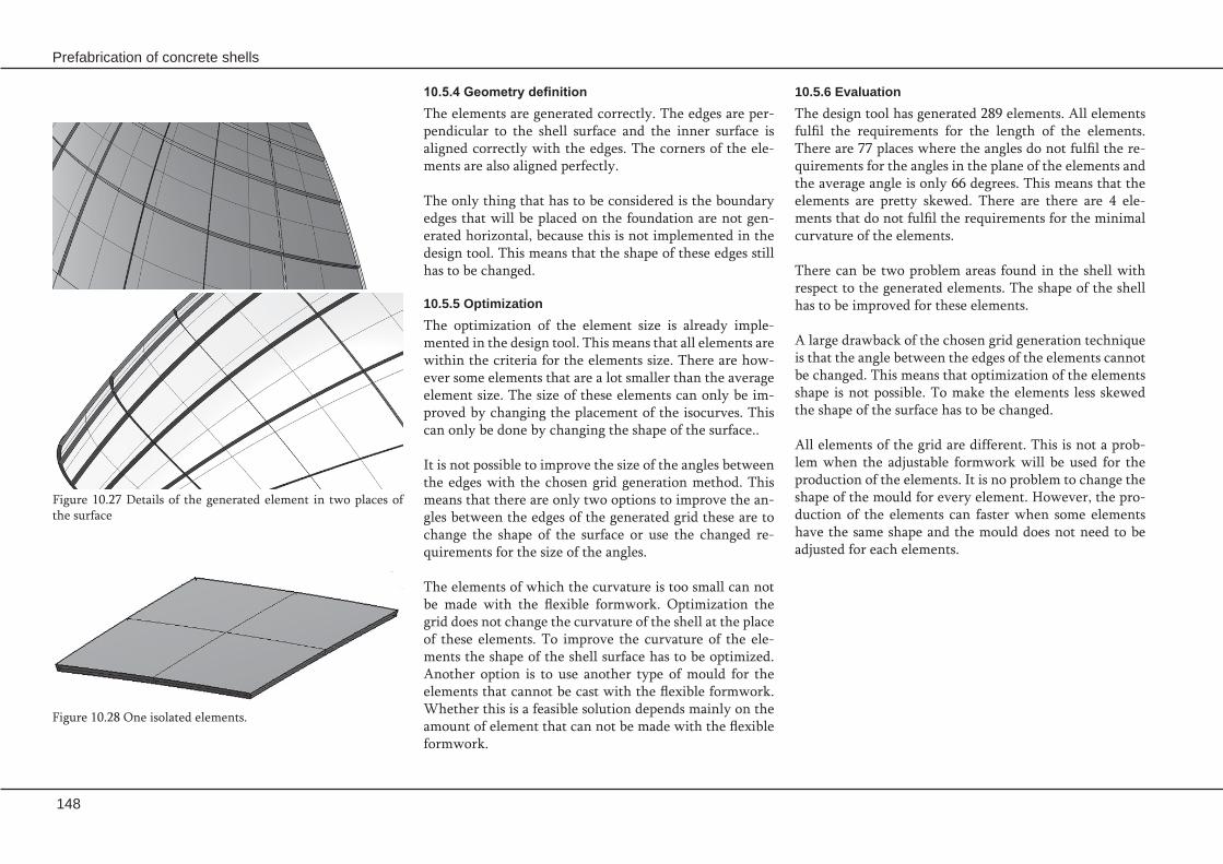
148
Prefabrication of concrete shells
Figure 10.27 Details of the generated element in two places of the surface
10.5.6 EvaluationThe design tool has generated 289 elements. All elements fulfil the requirements for the length of the elements. There are 77 places where the angles do not fulfil the re-quirements for the angles in the plane of the elements and the average angle is only 66 degrees. This means that the elements are pretty skewed. There are there are 4 ele-ments that do not fulfil the requirements for the minimal curvature of the elements.
There can be two problem areas found in the shell with respect to the generated elements. The shape of the shell has to be improved for these elements.
A large drawback of the chosen grid generation technique is that the angle between the edges of the elements cannot be changed. This means that optimization of the elements shape is not possible. To make the elements less skewed the shape of the surface has to be changed.
All elements of the grid are different. This is not a prob-lem when the adjustable formwork will be used for the production of the elements. It is no problem to change the shape of the mould for every element. However, the pro-duction of the elements can faster when some elements have the same shape and the mould does not need to be adjusted for each elements.
10.5.4 Geometry definition The elements are generated correctly. The edges are per-pendicular to the shell surface and the inner surface is aligned correctly with the edges. The corners of the ele-ments are also aligned perfectly.
The only thing that has to be considered is the boundary edges that will be placed on the foundation are not gen-erated horizontal, because this is not implemented in the design tool. This means that the shape of these edges still has to be changed.
10.5.5 Optimization The optimization of the element size is already imple-mented in the design tool. This means that all elements are within the criteria for the elements size. There are how-ever some elements that are a lot smaller than the average element size. The size of these elements can only be im-proved by changing the placement of the isocurves. This can only be done by changing the shape of the surface..
It is not possible to improve the size of the angles between the edges with the chosen grid generation method. This means that there are only two options to improve the an-gles between the edges of the generated grid these are to change the shape of the surface or use the changed re-quirements for the size of the angles.
The elements of which the curvature is too small can not be made with the flexible formwork. Optimization the grid does not change the curvature of the shell at the place of these elements. To improve the curvature of the ele-ments the shape of the shell surface has to be optimized. Another option is to use another type of mould for the elements that cannot be cast with the flexible formwork. Whether this is a feasible solution depends mainly on the amount of element that can not be made with the flexible formwork.
Figure 10.28 One isolated elements.

Case study
149
10.6 Production and constructionto be placed before the mould is brought in the deformed shape. This works very well for the edges in the middle of the shell, that are perpendicular to the surface. But the edges at the boundary of the shell are more difficult to form. These edges are flat and orientated horizontal. This means that the strips of these edges have to be in torsion before the mould is deformed. In this way the inserts become flat when the mould is brought into the curved shape. The orientation of the inserts with the flat mould also has to be calculated accurately to get a correct orien-tation of the edge of the cast element.
For the connections no inserts have to be placed into the elements. The only inserts that might be needed are some provision to lift the elements.
10.6.2 StorageFor the storage of the elements the frame introduced in Chapter 7 ‘Production and construction’ will be used. This frame ensures that no unnecessary deformation of the ele-ments occurs during storage of the elements.
This frame can also be used to transport the element from one location to the next. For example from the storage area in the factory on the truck and from truck to the stor-age area on the building site. When the frame is used to lift the elements no extra lifting loads are induced on the ele-ments, these loads are all taken by the frame. Besides this the frame also protects the elements during transport.
This shell consists of 289 elements. When all elements are produced before the construction the shell starts there are also 289 storage frames needed. These frames can be re-used for different projects, but prefabricated shell struc-tures will always be specials projects that are not built very often. So the construction of these special frames will increase building costs.
10.6.1 Production processThe production process consists mainly of the production of the prefabricated elements. The elements will be cast in a factory and transported to the building site after harden-ing. The elements will be cast using the adjustable mould as it is defined in Chapter 5 ‘Adjustable formwork’. The used concrete composite is hybrid fibre concrete.
Casting sequence
The casting sequence of the elements can be determined on the basis of the construction of the shell. The order of production of the elements will be the same as the placing order. With this production sequence it is least likely that the construction will be delayed due to problems with the production of the elements.
Casting process
Mould will be brought in the curved shape after casting, to prevent sag and flow of the wet concrete. The defor-mation of the partly hardened concrete may cause some extra stresses in the elements. The strength development of high performance concrete is relatively fast, but due to the large amounts of superplasticizer that are added to the mixture the strength developments is slowed down on the first day. Before the elements will be produced some test-ing has to be done to find the right combination between the amount of superplasticizer in the concrete, the work-ability of the concrete and the moment the mould will be deformed that will give the least extra stresses in the con-crete and the fasted production speed. The fact that the mould will be deformed after casting of the concrete makes that it is not possible to add any steel reinforcing bars to the elements.
Inserts
Because the concrete is cast before the mould is deformed the inserts that form the edges of the elements also have

150
Prefabrication of concrete shells
Before the elements can be placed the surface of the edg-es has to be roughened and cleaned carefully to ensure a good bonding between the element and the epoxy resin. After the epoxy has been applied on the edges of the al-ready placed elements the next element can be placed. Vi-bration can be used to achieve the required thickness of the epoxy joint.
During the placement of the elements the stability of the shell has to be ensured at all time. So each elements will be placed on a temporary scaffolding. This scaffolding makes that the elements are supported at all time and the crane time of each elements is minimized.
When all elements are placed and the connections have reached their final strength the scaffolding can be re-moved. At this moment the construction of the shell is almost finished, but the building process of the shell is not. At this time the glass facade in the arch can be placed and the work on finishing the building can start. This means that the electricity, isolation, floors etcetera can be in-stalled.
Figure 10.29 Building sequence of the shell.
10.6.3 Transport The elements will be transported from the factory to the building site by road. The elements are loaded with the storage frames on a truck. Depending on the exact size of the frame and the size of the truck between 6 to 12 ele-ments can be transported on one truck. This means that for the 289 element between 24 and 48 truck loads are needed to transport all elements from the factory to the building site.
10.6.4 Construction processBefore the construction of the actual shell can start the foundation of the shell has to be made. The foundation forms the basis of the shell and will be made out of in-situ concrete. When the construction works on the founda-tion are finished and prepared for the placement of the elements the construction of the shell can start.
The elements are placed one row at a time from bottom to the top of the shell. When the placement of the elements of one row is finished the placements of the elements of the next row can start. The construction of one row starts in the two ‘corners’ of the shell. Form that point the ele-ments are toward the middle of the back of the shell and to the arch in the front of the shell. The complete construc-tion process is visualized in appendix 5. By choosing this construction sequence in each row only one element has to be placed in between two other ele-ments on an element of the previous row. All other ele-ments can be placed on the element of the previous row next to one other element. This means that in each row there is only one element with which the torsion of the edges might give some difficulties with the placement. The element that might give these problems is located in the part of the shell which is least curved, and the edges of the elements are there also not to much in torsion.

Case study
151
Production and construction
Mould will be brought in the curved shape after cast- -ing, to prevent sag and flow of the wet concrete. This means that the inserts should be able to deform dur-ing the deformation of the mould. This production process makes the production of the inserts for the horizontal boundary edges more difficult.
The used connection system and the casting method -of the elements do not allow the application of steel reinforcing bars in the elements.
All elements of the grid are different. This is not a -problem when the adjustable formwork will be used for the production of the elements. It is no prob-lem to change the shape of the mould for every ele-ment. However, the production of the elements can faster when some elements have the same shape and the mould does not need to be adjusted for each ele-ments.
For the storage and transport of the elements spe- -cial frames will be used. The benefit of these frames is that they protect the elements against damage and unnecessary deformation, but the production of these frames is pretty expensive.
In the construction process of the shell there are some -elements that will be more difficult to place. It might be necessary to take some special measures in the de-sign of these elements, like increasing the thickness of the epoxy layer. Whether this is necessary has to be determined in the later phases of the design.
Structural analysis
The analysis of the results of the finite element analy- -sis show that the defections and stresses of the shell are withing the requirements. The largest deflections and stresses are present in the arch of the surface.
To improve the force transfer in the shell and ap- -proach the ideal of pure membrane action for all load cases the design has to be optimized.
Detailing
The glued connection will be used as connection sys- -tems for this shell structure. The main drawback of this system is the fact that it is still an experimental connection system and the long term performances is not jet fully known. This means that in the next phased of the design of this shell special attention has to be paid to this aspect of the connection system. An-other aspect that has to be looked at closely is wheth-er the relative small joints between the elements give problems with the placement of the elements.
The foundation has to be able to transfer the forces -form the shell correctly. The horizontal forces on the foundation are relatively large.
Geometry definition
A large drawback of the chosen grid generation tech- -nique is that the angle between the edges of the ele-ments cannot be changed. This means that optimiza-tion of the elements shape is not possible.
There can be two problem areas found in the shell -with respect to the generated elements. The shape of the shell has to be improved for these elements.
10.7 Conclusion

152
Prefabrication of concrete shells

Conclusions & RecommendationsIn this chapter the conclusions and recommendations of this Master’s thesis are given.

154
Prefabrication of concrete shells

Conclusions & recommendations
155
There are different types of connection systems for -the connection of the elements in the structure. There is no system that is the most optimal in all cases so the best connection system has to be chosen for each in-dividual design.
The integral design process of a prefabricated con- -crete shell is quite complicated due to the many dif-ferent aspects that have to be taken into account at the same time and the many different possibilities to optimize the design. For most aspects there is not one solution that is the most optimal design choice for every design.
The developed design tool is capable of generating a -grid over a lot of different surfaces. However not for every surface an optimal grid is generated. A large drawback of the used grid generation technique is that the angle between the grid lines cannot be op-timized.
To make a next step in the development of prefabri- -cated concrete shell it is advised to really build a pre-fabricated shell structure of which the elements are made with the adjustable formwork.
In the following the general conclusions of this thesis are given. The conclusions are discussed point wise and are ordered corresponding to their occurrence in the thesis.
The structural analysis of thin shells is quite complex -due to the three dimensional shape of the shell and the combination of in-plane and bending stresses in the shell. The introduction of finite element methods made the analysis of shells easier, but to the struc-tural behaviour of prefabricated concrete shells and the influence of the connections and the place of the connection on the structural behaviour still much re-search has to be done.
From a theoretical point there is no optimal grid gen- -eration technique that results in the best grid for every surface. The most suitable grid generation technique for a surface depends on the geometry of the surface, the architectural design and the structural layout.
The high performance fibre reinforced concrete com- -posites form a good solution for the use in prefabri-cated concrete shell structures. But more research has to be done to define regulations for the design of con-structions in high performance fibre reinforced con-crete composites.
At the moment large steps in the development of the -adjustable formwork are made by the construction of a large scale testing model.
Conclusions

156
Prefabrication of concrete shells

Conclusions & recommendations
157
Recommendations
157
In the following the recommendations of this thesis are given. The recommendations are discussed point wise and are ordered corresponding to their occurrence in the the-sis.
More research to the structural behaviour and the -stability of prefabricated concrete shell structures and the influence of the connections has to be per-formed.
For the increase of the application of high perform- -ance fibre reinforced concrete composites it is advised that a design code is developed for these type of con-crete composites.
More research has to be done to the development of -the adjustable formwork.
More research has to be done to the development of -connection systems for prefabricated concrete shell structures with elements made of high performance fibre reinforced concrete.
The segmentation of the shell is now made without -interaction with the structural analysis of the shell. A research has to be performed to with whether the structural performance might be improved when the segmentation is based on the structural analysis of the shell.
More research has to be done to the construction of -the prefabricated concrete shell. The advised method to do this research is with the construction of a real prefabricated concrete shell.

158
Prefabrication of concrete shells

References

160
Prefabrication of concrete shells

References
References
Books and reports
[1] Bentur, A. & Mindess, S.; Fibre reinforced cementitious composites 2nd edition; Taylor & Francis Group London and New York; 2007[2] Bennenk, H.W., Kuik, M.E.M.E. van, Waperom, H.H.; Prefab beton, deel 1; BFBN; Woerden; 2003[3] Blauwendraad, J en Hoefakker, J.H.; Theory of Shell, Course CT5143; Delft University of Technology; September 2004[4] Bruijn, H.J. de; Literatuur- en voorstudie: hogere sterkte beton nader belicht; Master’s Thesis; TUDelft; December 2005[5] Diks, M.E.; Translucent sandwich systeem voor dubbel gekromde toepassingen; Master’s Thesis; TUDelft; January 2005[6] Fehling, E., Schmidt, M., Stürwald, S.; Ultra High Performance Concrete (UHPC), Proceedings of the Second International Symposium on Ultra High Performance Concrete; Structural Materials and Engineering Series, Heft 10; Kassel, Germany; 5-7 May 2008[7] Grunewald, S.; Performance-based design of self-compacting fibre reinforced concrete; TUDelft; 2004[8] Haas, A.M.; Design of thin concrete shells, volume 1, positive curvature index; John Wiley & Sons New York & London; 1962[9] Handboek uitvoering betonwerken; Stubeco/ betonvereniging; 1e druk; Gouda; 2005[10] Jansen, H.; Prefabricage bij blobconstructies, een civiele kijk op blobarchitectuur; Master’s Thesis; TUDelft; november 2004[11] Lappa, E.S.; High strength fibre reinforced concrete, static and fatigue behaviour in bending; Phd Thesis; TUDelft; 2007 [12] Liseikin, V.D.; Grid Generation Methods; Springer; Berlin; 1999[13] Markovic, I.; High-Performance Hybrid-Fibre Concrete, Development and Utilisation; Phd Thesis; TUDelft; 2006[14] Nederlandse norm NEN-EN 1990 Eurocode – Grondslagen van het constructief ontwerp; December 2002[15] Nederlandse norm NEN-EN 1991-1 Eurocode 1: Belastingen op constructies; December 2002[16] Nederlandse norm NEN-EN 1992-1-1 Eurocode 2: Ontwerp en berekening van betonconstructies –Deel 1-1: Algemene regels en regels voor gebouwen; April 2005[17] Peerdeman, B; Analysis of Thin Concrete Shells Revisited: Opportunities due to Innovations in Materials and Analysis Methods; Master’s Thesis; TUDelft; June 2008[18] Pressley, A.; Elementary Differrential Geometry; Springer Undergraduate Mathematics Series; London; 2001[19] Roosbroeck, van M.K.H.M.; The Construction of prefab concrete shells, morphology-segmentation- material-production method; Master’s Thesis; TUDelft; February 2006[20] Ruhle, H.; Raumliche Dachtragwerke Construction und Ausfuhrung, Band 1; Verlagsgesellschaft Rudolf Muller; Koln-Braunsfeld; 1969[21] Schmidt, M., Fehling, E., Geisenhanslüke, C.; Ultra High Performance Concrete (UHPC), Proceedings of the International Symposium on Ultra High Performance Concrete; Structural Materials and Engineering
161
162
Prefabrication of concrete shells
Series, Heft; Kassel, Germany;13-15 September 2004[22] Schodek, D.L.; Structures fifth edition; Pearson Prentice Hall; 2004[23] Thompson, J.F., Soni, B.K., Weatherill, N.P., editors; Handbook of grid generation; CRC press; 1999, online version [24] Vambersky, Prof. dipl.-ing J.N.J.A., Wagemans, Prof. ir. L.A.G., Coenders, Ir. J.L.; Structural Design-Special Structures, course CT5250; Delft University of Technology; April 2006[25] Yuguang, Y; Bending behaviour of a High Performance Concrete overlay on an orthotropic steel deck; Master’s Thesis; TUDelft; August 2007
Articles
[26] Adeeb, S.M., Scholefield, B.W.J., Brown, T.G., Shrive, N.G., Kroman, J., Perry, V.H. and Tadros, G.; Modelling, testing, and construction of the first Ductal® canopy in the world; Canadian Journal of Civil Engineering; volume 32 2005; page 1152-1165[27] Bayasi, Z. & Zeng, J.; Flexural behaviour of slurry infiltraded mat concrete (SIMCON); Journal of materials in civil engineering; November 1997; page 194-199[28] Detail; Flugzeugmuseum in Duxford, England; Volume 38; 1998; number 6; page 988-991[29] Fielt, R.; Creatief met beton, Folly in Hilversum laat vorderingen constructietechniek zien; De ingenieur; jaargang 117; nummer10/11; 10 juni 2005[30] Haas, Ir. M. de; Comeback voor betonnen schaalconstructies? Stijve verbindingen voor prefab schalen; Cement; 2008; number 3[31] Huijben, R.N.J.; Geen brug te ver, Diverse prefab betonsoorten; Cement; 2002; number 4; page 34-39[32] Kaptijn, N.; Toekomstige ontwikkelingen van zeer-hogesterktebeton, De visie van Rijkswaterstaat; Cement; 2002, number 2; page 56-63[33] Kempkes, M.; Das Neue Tempodrom am anhalter Bahnhof in Berlin; Stahlbau; volume 71; 2002; number 3; page 165-170[34] Markovic, dr.ir.I.;Hybride Vezelbeton (1) Ontwikkeling en toepassingsrichting;Cement; 2007; number 4[35] Medwadowski, S.J.; Concrete thin shell roofs at the turn of the millennium; Current and emerging technologies of shell and spatial structures; proceedings of the colloquium held on 28-30 April 1997 in Madrid; edited by J. Abel, R. Astudillo and N.K. Srivastava; 1997; page 9-22.[36] Rossi, P.; Ultra-High-Performance Fiber-Reinforced Concretes; a French perspective on approaches used to produce high-strength, ductile fiber-reinforced concrete; Concrete International, December 2001[37] Rossi, P.; Development of new composite materials for construction; Proceedings of the Institution of Mechanical Engineers, Part L: Journal of Materials: Design and Applications; Volume 219; no. L1; Februari 2005; page 67-74[38] Shawnessy LRT station award press release; Lafarge North America, Canada, 2006[39] Slaich, J. and Schober, H.; Glass roof for the Hippo House at the Berlin Zoo; Structural Engineering International; Volume 7; 1997; number 4; page 252-254 [40] Vicenzino, E., Culham, G., Perry, V.H., Zakariasen, D., Chow, T.S. ; First use of UHPFRC in thin precast concrete roof shell for Canadian LRT station; PCI journal; sept/oct 2005; page 50-67

References
163
[41] Walraven, prof.dr.ir. J.; Waar gaan we naartoe met ons beton? Beton als conventioneel bouwmateriaal; Cement; 2002; number 4; page 6-13
Interviews
[42] Interview with Daan Rietbergen about his PhD-thesis.
Internet pages
[43] en.wikipedia.org/wiki/Finite_element_method date 14-4-2008[44] en.wikipedia.org/wiki/Finite_element_method_in_structural_mechanics date 15-4-2008[45] en.wikipedia.org/wiki/Finite_element_analysis date 14-4-2008[46] en.wikipedia.org/wiki/NURBS date 5-3-2008[47] en.wiki.mcneel.com/default.aspx/McNeel/RhinoScript.html[48] picasaweb.google.com/rs.tulipmed/HastaEspana/photo#5064723626394534210[49] www.asce.org/pressroom/news/display_press.cfm?uid=2650 date 24-4-2007[50] www.bouwwereld.nl/web/EenProjectUitgebreid.htm?contentid=648&jumpto=intro&showall=true#intro date 16-11-2007[51] www.bsieiffage.com/ date 24-8-2007[52] www.ductal-lafarge.com[53] www.fibretech.org date 7-02-2008[54] www.franken-architekten.de[55] ww.gmp-architekten.de/2projects/tempodrom/tdrom.html date 6-6-2007[56] www.grca.org.uk date 7-02-2008[57] www.imagineductal.com date 4-6-2007[58] www.lafargenorthamerica.com/wps/portal/!ut/p/kcxml/04_Sj9SPykssy0xPLMnMz0vM0Y_QjzKL N4p3CwbJgFjGpvqRyCIG8Y5wAV-P_NxU_SB9b_0A_YLc0IhyR0dFAKjZGbQ!/delta/base64xml/L3dJdyEvd 0ZNQUFzQUMvNElVRS82XzJfRlM!?WCM_GLOBAL_CONTEXT=/wps/wcm/connect/LNA/Library/ Project/Product/Ductal/Shawnessy+LRT+Station/Shawnessy_LRT_Station date 24-4-2007[59] www.mero.de/uploads/tx_cwtcartoongallery/free_ret_stru_e.pdf date 8-2-2008[60] www.nookindustries.com[61] www.peri.de/ww/en/projects.cfm?fuseaction=showreference&reference_ID=449 Date 5-6-2007[62] www.rdw.nl/tet[63] www.rhino3d.com/nurbs.htm date 5-3-2008[64] www.structurea.de[65] www.reconstructivism.net/[66] www.website.hurksbeton.nl/main.php?cm=79%2C80%2C122_1cCgGh1_oupxnHp7g1WQOV_588&cm_ wfs=589.1063&prid=92 date 24-4-2007 [67] http://www.sika.nl/tds_sikadur30_nl.pdf

Prefabrication of concrete shells
164
Appendices

166
Prefabrication of concrete shells

Appendix
167
Personal data
Name: Eline den Hartog Student number: 1014277Adress: Frank van Borselenstraat 44, 2613 NM DelftTelephone: 06-14277450E-mail: [email protected]
Graduation committee
Prof. ir. L.A.G. WagemansFaculty of Civil Engineering am Geoscienceroom 1.60 ST2T: 015- 2784752E: [email protected]
Ir. J.L. CoendersFaculty of Civil Engineering am Geoscienceroom: 1.60 ST2 T: 015-2785711 E: [email protected]
Ir. A. BorgartFaculty of ArchitectureT: 015-2784157E: [email protected]
Dr. ing. S. GrunewaldFaculty of Civil Engineering am Geoscienceroom: 1.04 ST2T: 015-2784580E: [email protected]
Appendix 1 Personal data and graduation committee

168
Prefabrication of concrete shells

Appendix
169
Appendix 2 Gaussian curvature
Figure 2.3. The Jahrhunderthalle Hoechst (Frankfurt, 1963) is an example of a sinclastic curved structure. [64]
Figure 2.4 The Saddledome (Calgary, 1983) is an example of an anticlastic curved structure. [64]
The second one is the Gaussian curvature, the product of the two principal curvatures:
kg = k1• k2The sign of the Gaussian curvature can be used to charac-terise the local shape of the surface. The classification of surfaces by Gaussian curvature results in four classes:
Plane
The Gaussian curvature is equal to zero. In this case both principal curvatures are equal to zero; k1= 0, k2 = 0. This means that in both principal directions the radius of cur-vature is infinite and the surface is flat.
Simply curved
The Gaussian curvature is equal to zero. In this case only one of the principal curvatures is equal to zero; k1= 0, k2 ≠ 0. These surfaces are single curved and developable.
Figure 2.2 Radius of curvature r of a general curve C. [59]
Figure 2.1 Intersection of different planes with a surface. [3]
At any point A (See Figure 2.1) on a surface a vector that is normal to the surface can be defined. A plane that in-tersects the surface and contains a normal is considered to be normal to the middle surface at that point. The plane curve formed by the intersection of the plane, that con-tains a normal of the surface, with the surfaces is called normal section of the surface at that point. Every point has an infinite amount of normal sections and they all have a local curvature k and a radius of curvature r. The local curvature is defined as the inverse of the radius of curvature. The two plane curves, with the minimal and maximal value of curvature, are called the principal sec-tions and their curvatures at point A are denoted as k1 and k2. These principal sections are orthogonal to each other. With these principal sections two properties of the surface at that point can be determined. The first one is the mean curvature:
H = ½ (k1 + k2)

170
Prefabrication of concrete shells
Figure 2.5 Surface classification by Gaussian curvature. [59]
Anticlastic
The Gaussian curvature is negative. This means that the principal curvatures have different signs. This results in a double curved surface. Examples of anticlastic surfaces are for example found as sable shape surfaces or in tensioned membrane surfaces.
A developable surface is defined as a surface that can be de-veloped into a plane form without cutting and/or stretch-ing their middle surface. An example of this type of sur-face is the cylindrical shell.
Synclastic
The Gaussian curvature is positive. This means that both principal curvatures have the same sign. This results in a double curved surface. Examples of synclastic structures are domes or elliptic paraboloids.

Appendix
171
Appendix 3 The test surfacesThe three test surfaces with a projected grid.
The three test surfaces with a Rhino mesh.
Figure 3.1 Surface of revolution with a projected grid. Figure 3.3 Surface 2 with a projected grid.Figure 3.2 Surface 1 with a projected grid.
Figure 3.4 Surface of revolution with a Rhino mesh. Figure 3.6 Surface 2 with a Rhino mesh.Figure 3.5 Surface 1 with a Rhino mesh.

172
Prefabrication of concrete shells
The three test surfaces with a isocurve grid, before rebuild-ing.
The three test surfaces with a isocurve grid, after rebuilding.
Figure 3.8 Surface 1 with an isocurve grid.Figure 3.7 Surface of revolution with an isocurve grid.
Figure 3.12 Surface 2 with an isocurve grid. Maximum deviation with rebuilding is 0,00589 m
Figure 3.11 Surface 1 with an isocurve grid. Maximum deviation with rebuilding is 0,00693 m
Figure 3.10 Surface of revolution with an isocurve grid. Maximum deviation with rebuilding is 0,00894 m
Figure 3.9 Surface 2 with an isocurve grid.
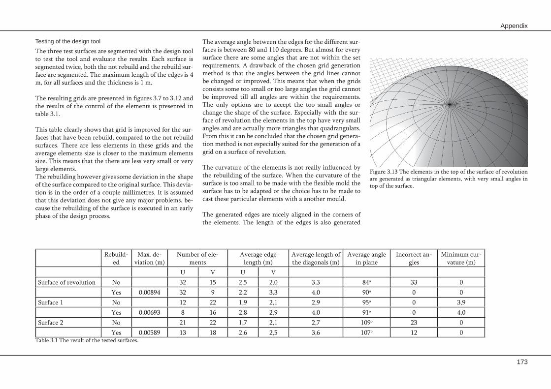
Appendix
173
Testing of the design tool
The three test surfaces are segmented with the design tool to test the tool and evaluate the results. Each surface is segmented twice, both the not rebuild and the rebuild sur-face are segmented. The maximum length of the edges is 4 m, for all surfaces and the thickness is 1 m.
The resulting grids are presented in figures 3.7 to 3.12 and the results of the control of the elements is presented in table 3.1.
This table clearly shows that grid is improved for the sur-faces that have been rebuild, compared to the not rebuild surfaces. There are less elements in these grids and the average elements size is closer to the maximum elements size. This means that the there are less very small or very large elements. The rebuilding however gives some deviation in the shape of the surface compared to the original surface. This devia-tion is in the order of a couple millimetres. It is assumed that this deviation does not give any major problems, be-cause the rebuilding of the surface is executed in an early phase of the design process.
Rebuild-ed
Max. de-viation (m)
Number of ele-ments
Average edge length (m)
Average length of the diagonals (m)
Average angle in plane
Incorrect an-gles
Minimum cur-vature (m)
U V U V Surface of revolution No 32 15 2,5 2,0 3,3 84o 33 0
Yes 0,00894 32 9 2,2 3,3 4,0 90o 0 0Surface 1 No 12 22 1,9 2,1 2,9 95o 0 3,9
Yes 0,00693 8 16 2,8 2,9 4,0 91o 0 4,0 Surface 2 No 21 22 1,7 2,1 2,7 109o 23 0
Yes 0,00589 13 18 2,6 2,5 3,6 107o 12 0Table 3.1 The result of the tested surfaces.
The average angle between the edges for the different sur-faces is between 80 and 110 degrees. But almost for every surface there are some angles that are not within the set requirements. A drawback of the chosen grid generation method is that the angles between the grid lines cannot be changed or improved. This means that when the grids consists some too small or too large angles the grid cannot be improved till all angles are within the requirements. The only options are to accept the too small angles or change the shape of the surface. Especially with the sur-face of revolution the elements in the top have very small angles and are actually more triangles that quadrangulars. From this it can be concluded that the chosen grid genera-tion method is not especially suited for the generation of a grid on a surface of revolution.
The curvature of the elements is not really influenced by the rebuilding of the surface. When the curvature of the surface is too small to be made with the flexible mold the surface has to be adapted or the choice has to be made to cast these particular elements with a another mould.
The generated edges are nicely aligned in the corners of the elements. The length of the edges is also generated
Figure 3.13 The elements in the top of the surface of revolution are generated as triangular elements, with very small angles in top of the surface.

174
Prefabrication of concrete shells
correctly. Due the generation of the edges perpendicular to the surface the edges can be in torsion. The torsion of the edges is influenced by the amount of curvature in the shell. The the curvature of the shell changes rapidly there is more torsion in the edges than when the curvature of the shell changes only slowly or regularly. Also the fact whether the surface is synclastic or anticlastic might influ-ence the torsion in the edge. It is expected that the amount of torsion in the edges is smaller for a synclastic surface than for a anticlastic surface.
The shape of the boundary edges should be dependent on the shape of the foundation. The edges of the elements that are placed on the foundation should be horizontal. This is not implemented in the design tool, so these edges are still generated perpendicular to the surface.
Figure 3.14 The edges of the surface of revolution are almost not in torsion probably due to the regular change of the curvature of the surface.
Figure 3.15 This detail of surface 1 shows that the edges of the elements are in torsion.
Figure 3.16 This detail of surface 1 shows that the torsion of the edge is larger when the curvature of the surface is larger.
Figure 3.17 This detail of surface 2 shows that these edges are also in torsion.
The inner surface of the shell is nicely aligned with the edges of the elements. Because the boundary edges are generated perpendicular to the surface and not horizon-tal at this point not problems with the alignment of the edges with the inner surface occur. When the boundary edges are generated horizontally the shape of the inner surface of these elements has to be adapted to the hori-zontal edge.

Appendix
175
Figure 4.1 The option control box of the Rhino mesh tool.
Appendix 4 Rhino mesh toolIn this appendix the process with which the mesh is gen-erated and the different control options are explained.
The rhino mesh tool creates polygon meshes from NURBS surfaces or polysurfaces. Surfaces are meshed in a two step process. First a regular quad mesh is created and then that mesh is refined by splitting some quads into 4 smaller quads. The ‘maximum aspect ratio’, ‘maximum edge length’ and ‘minimum initial grid quads’ settings control the gen-eration of the initial mesh. The ‘maximum angle’, ‘maxi-mum edge length’, ‘minimum edge length’, and ‘maximum distance, edge to surface’ settings determine which initial quads get split up into smaller quadrangles.
Density
This option uses a formula to control how close the poly-gon edges are to the original surface. Values between 0 and 1 can be used, larger values result in a mesh with a higher polygon count.
Maximum angle
This option controls the maximum allowable change be-tween the surface normal at any point and the mesh ver-tex. Two vertices are neighbors if they are at the ends of a facet edge. Smaller values result in slower meshing, more accurate meshes, and higher polygon count.
Maximum aspect ratio
Surfaces are initially tessellated with a regular quadrangle mesh, which is refined after generating. The initial quad mesh is constructed so that on average, the maximum as-pect ratio of the quads is less than or equal to Maximum aspect ratio.
Smaller values of the aspect ratio result in slower mesh-ing and a higher polygon count with more equilateral and nicely shaped polygons.
Minimum edge length
If any edge is shorter than the Minimum edge length, no further division of the mesh faces occurs. This length is, approximately, the minimum edge length of the quads in the initial mesh grid.
Maximum edge length
The polygons are divided until all polygon edges are short-er than the maximum edge length. This length is, approxi-mately, the maximum edge length of the quads in the ini-tial mesh grid.
Maximum distance, edge to surface
Polygons divide until the distance from a polygon edge midpoint to the NURBS surface is smaller than this value. This distance is also the approximate maximum distance from polygon edge midpoints to the NURBS surface in the initial mesh grid.
Minimum initial grid quads
With this value the number of quadrangles per surface in the initial mesh grid can be set. Bigger values result in slower meshing, more accurate meshes and a higher poly-gon count with more evenly distributed polygons. Setting this value to zero turns off the option.
Refine mesh
After its initial meshing, Rhino uses a recursive process to refine the mesh until it meets the criteria defined by ‘maximum angle’, ‘minimum edge length’, ‘maximum edge length’, and ‘maximum distance, edge to surface’ op-tions. No refinement results in faster meshing, less accu-rate meshes with a lower polygon count
Jagged seams
All surfaces are meshed independently and Rhino does not stitch the edges of joined surface edges together. If Jagged seams is not checked, watertight meshes are created. This causes faster meshing, a lower polygon count and cracks between joined surfaces in the rendered image.
Simple planes
All planar surfaces are meshed by meshing the surface edges and then filling the area bounded by the edges with triangles.
Pack textures
When polysurfaces are meshed, the packed texture coor-dinates are created. A packed texture is a partition of the unit square into disjoint sub-rectangles so that one bitmap can be used to apply independent textures to each face of the polysurface.

176
Prefabrication of concrete shells

Appendix
177
Appendix 5 Case study
Case study designRebuild No YesMaximum deviation (mm) 0,688Number of elements U 18 17
V 17 17Maximum edge length (m) U 3,00 2,95
V 2,64 2,63Minimum edge length (m) U 0,68 0,39
V 1,25 1,24Average edge length (m) U 1,49 1,58
V 2,16 2,10Average length of the diagonals (m)
dir1 2,02 1,98
dir2 3,15 3,14Average angle in plane 64o 66o
Incorrect angles 77 70Minimum curvature (m) 0 0
Table 5.1 Results of the generated grid of the case study design
Segmentation and element generationThe design tool is used to generate the grid over the case study design, for both the original and the rebuild surface. The results of the generated elements are given in table 5.1.
Maximum length of the edges: 3 m -Thickness of the shell is 100 mm. -
The first thing that can be seen on this results is that the difference between the original and the rebuild surface is much smaller than with the test surfaces of Chapter 9. This makes that the grid of the rebuild surface is not absolutely better than the original grid. Because the small difference between the two grids only the grid of the rebuild surface will be shown and discussed here. This grid will be used, because the number of elements in this grid is smaller and the number of elements with wrong angles is also smaller than in the original surface.
Element size
The results in table 5.1 show that the length of the edges in the U-direction is smaller than the length of the edges in the V-direction. This means that the shape of the edges is more rectangular that square. The size of the different elements does not differ a lot for large parts of the surface. There are only two areas where very small elements are generated. These areas are marked with two circles in Figure 5.4. The shape of these elements is also not very optimal. So these elements have to be im-proved during the optimization of the generated grid.
Figure 5.1 The problem areas of the grid the element size and element curvature are marked with the two circles.

178
Prefabrication of concrete shells
Construction processIn the following figures the placing sequence of the ele-ments is visualized.

Appendix
179

180
Prefabrication of concrete shells
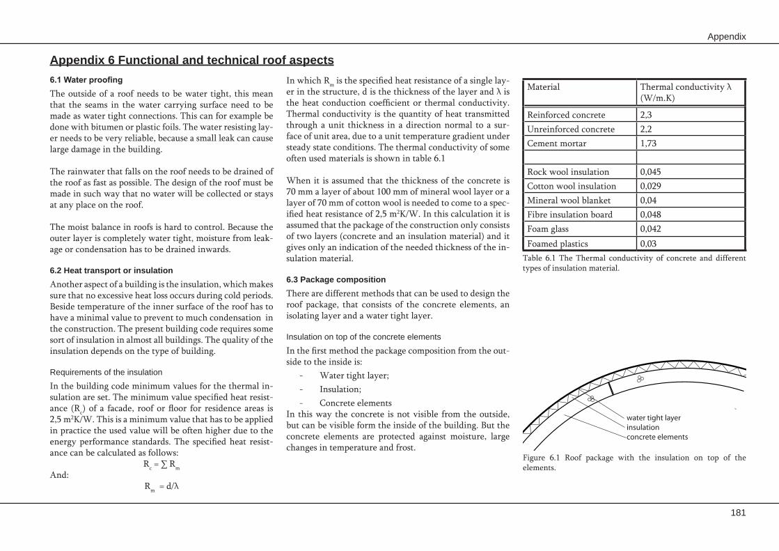
Appendix
181
In which Rm is the specified heat resistance of a single lay-er in the structure, d is the thickness of the layer and λ is the heat conduction coefficient or thermal conductivity. Thermal conductivity is the quantity of heat transmitted through a unit thickness in a direction normal to a sur-face of unit area, due to a unit temperature gradient under steady state conditions. The thermal conductivity of some often used materials is shown in table 6.1
When it is assumed that the thickness of the concrete is 70 mm a layer of about 100 mm of mineral wool layer or a layer of 70 mm of cotton wool is needed to come to a spec-ified heat resistance of 2,5 m2K/W. In this calculation it is assumed that the package of the construction only consists of two layers (concrete and an insulation material) and it gives only an indication of the needed thickness of the in-sulation material.
6.3 Package compositionThere are different methods that can be used to design the roof package, that consists of the concrete elements, an isolating layer and a water tight layer.
Insulation on top of the concrete elements
In the first method the package composition from the out-side to the inside is:
Water tight layer; -Insulation; -Concrete elements -
In this way the concrete is not visible from the outside, but can be visible form the inside of the building. But the concrete elements are protected against moisture, large changes in temperature and frost.
6.1 Water proofingThe outside of a roof needs to be water tight, this mean that the seams in the water carrying surface need to be made as water tight connections. This can for example be done with bitumen or plastic foils. The water resisting lay-er needs to be very reliable, because a small leak can cause large damage in the building.
The rainwater that falls on the roof needs to be drained of the roof as fast as possible. The design of the roof must be made in such way that no water will be collected or stays at any place on the roof.
The moist balance in roofs is hard to control. Because the outer layer is completely water tight, moisture from leak-age or condensation has to be drained inwards.
6.2 Heat transport or insulationAnother aspect of a building is the insulation, which makes sure that no excessive heat loss occurs during cold periods. Beside temperature of the inner surface of the roof has to have a minimal value to prevent to much condensation in the construction. The present building code requires some sort of insulation in almost all buildings. The quality of the insulation depends on the type of building.
Requirements of the insulation
In the building code minimum values for the thermal in-sulation are set. The minimum value specified heat resist-ance (Rc) of a facade, roof or floor for residence areas is 2,5 m2K/W. This is a minimum value that has to be applied in practice the used value will be often higher due to the energy performance standards. The specified heat resist-ance can be calculated as follows:
Rc = ∑ RmAnd:
Rm = d/λ
Appendix 6 Functional and technical roof aspects
Material Thermal conductivity λ (W/m.K)
Reinforced concrete 2,3Unreinforced concrete 2,2Cement mortar 1,73
Rock wool insulation 0,045Cotton wool insulation 0,029Mineral wool blanket 0,04Fibre insulation board 0,048Foam glass 0,042Foamed plastics 0,03
Table 6.1 The Thermal conductivity of concrete and different types of insulation material.
water tight layerinsulationconcrete elements
Figure 6.1 Roof package with the insulation on top of the elements.

182
Prefabrication of concrete shells
method is that it is more expensive due to the concrete facade elements.
Sandwich element
A sandwich element is composed of two layers of concrete with an insulation layer in between. The three layers are attached to each other to form a composed element. The benefit of this type of element is that the inner and outer layer of concrete can work together. This makes that the thickness of these layer might be reduced due to a more optimal distribution of the material. The production of these sandwich elements is a lot more complicated than the production of the normal double curved elements. This makes the production of the ele-ments also a lot more expensive. A benefit of the use of sandwich elements is that the insulation is integrated into the element and does not need to be placed on the struc-ture on site.
6.4 EvaluationFrom the point of view of moist balance in the roof, water tightness and insulation the first and the last two methods can have the same performance quality. The second method performs a lot worse from the as-pect of building physics, and it is not advisable to use this method. A drawback of sandwich elements is that the production is more complicated, but this might be compensated by the better mechanical performance due to a better mate-rial distribution. But in general it is better to use sandwich element as facade element, that do not have a load bearing function. Because it is very hard to connect the two con-crete layers of load bearing sandwich element in such way that they work together properly.
Whether the first or the third method is used depends mainly on the aesthetic wishes from the architect and fu-ture owner of the building and budget of the project.
Insulation under the concrete
In this method the concrete forms the outer layer of the structure and the insulation is placed under the concrete elements. The concrete element can be covered with a wa-ter tight layer or can be constructed in such way that they form water tight layer. The inside of the insulation is cov-ered with some finishing layer. With this method the ele-ments are visible on the outside of the structure. But the concrete elements are exposed to temperature changes, what can damage the concrete. Beside this the moist bal-ance in this type of package is not very optimal.
Double concrete layer
In this last method the following package composition from the outside to the inside is used:
Concrete facade elements; -Water tight layer; -Insulation; -Load bearing concrete elements. -
In this way the concrete can visible on both the outside and inside of the shell and at the same time an optimal roof package composition can be used. A drawback of this
water tight layerupper part of sandwich elementsinsulationbottom part of sandwich elements
Figure 6.4 Package composition of the shell composed of sandwich elements.
water tight layerconcrete elementsinsulationInterior finising
Figure 6.2 Package composition with the insulation under the elements.
concrete facade elementswater tight layerinsulationconcrete elements
Figure 6.3 Package composition with concrete elements on the inside and outside.