Embed Size (px)
Citation preview

Prefabricated
Page SCP-Steel Cased Pipe
1
Foreword Distant heating steel-cased piping fulfils all the demands made nowadays of modern and future-oriented distant -heating systems. Steel-cased piping has been used abroad for 80 years and in Europe for 50 years in the distant-heating field and has proven itself well suited to the purpose during this time. The German Distant-Heating Group (AGFW) and the German Federal Distant-Heating Piping Association (BFW) recommend steel-cased piping as safe. The major advantages compared to other types lie in the safe design, the rapid laying, the wide range of applications and uses, the pre-fabrication ex works, and the additional metrology and control systems. The steel-cased piping is a chambered system under vacuum. ISOBRUGG manufactures steel-cased piping in accordance with the CE-Certification 97/23EG Modul A1.

Prefabricated
Page SCP-Steel Cased Pipe
2
Applications ISOBRUGG steel-cased piping is suitable for use with all the media, temperatures, piping dimensions and pressure stages standard in distant heating and cooling depending on the piping materials and sidewall thickness. In addition, it is also used in industry as product piping.
Standard applications warm water up to +200C hot water domestic hot water thermal oil condensate High temperatures steam up to +400C hot air and gases Low temperatures chemical products (safety piping) to -30C cooling water, refrigeration Isobrugg steel-cased piping is excellent for difficult ground conditions wet ground subsidence-endangered areas stream crossings (drains) road crossings
for roadwork's and under concrete surfaces
transport piping Special uses of steel-cased chambered piping are: laying where this is subject to WHG § 9 and as safety piping in accordance with TRbF and VbF. Steel-cased piping dimensions and design data
Carrier pipe DIN 25 to DN 1200 Temperatures up to 400 C Special tailored types on request Pressure stages up to PN 64

Prefabricated
Page SCP-Steel Cased Pipe
3 INDEX OF CONTENTS
Product Description - System description - Technical Specifications
Components - Standard lengths - Support - Anchor - Bellows-type termination - Wall bushing - Bends - T-joints - Reducers - Compensating exapansion elements - Steel shaft
Accessories - Cathodic corrosion protection - Insulating flanges - Vacuum appliances - Vacuum pressure monitoring devices
Design - Technical Requirements for fabrication - Sample sectional drawing - Steel casing selection table - Selection of insulation material thickness - Determination of casing dimensions - Table of heat expansion - Seamless inner pipe table - Welded inner pipe table - Steel-cased piping selection table - Natural expansion tolerance - Prestressing

Prefabricated
Page SCP-Steel Cased Pipe
4 System Description
Steel-cased piping has been field-proven over decades as a “steel-in-steel” piping system for laying direct in the ground, suitable for transporting distant heat, steam, condensate and other media. Both the straight special units up to 16 metres in length and all the system-typical components such as bends, junctions, anchors, supports, etc. are pre-fabricated ex works. This means greater safety by comparison with on-site assembly. Steel-cased piping is suitable for all the application areas and operating conditions met in practise, but especially for extremely high temperatures and pressures. Strictly project-related pre-fabrication ensures the economic relationship of production costs to operating needs. The choice of carrier piping specification, determination of insulation thickness and calculation of the casing nominal dimensions is always dependent on the specific operating conditions. The gas- and water-tight welding of the carrier piping to the casing piping in shaft and con- struction bushings is standard in steel-cased piping. It is the pre-condition for the evacuation of the space between the carrier and casing piping. This evacuation ensures removal of any residual damp. At the same time, the insulation of the piping is greatly improved. Vacuum maintenance and monitoring ensures excellent means of checking that the system does not leak. This ensures safety during the operation of the system. Further safety measures are the carefully project-related cathodic corrosion-proofing preven- ting external corrosion of the casing piping. In addition, electronic monitoring devices warn immediately of any damp entering the insulation. The robust tailored design on the basis of long experience in building and using this piping sy- stem makes steel-cased piping a top-quality, safe transport means for all temperatures.

Prefabricated
Page SCP-Steel Cased Pipe
5 Technical Specification
Material-specific standard components Casing piping Longitudinally or spirally welded steel piping, dimensions according to DIN 2458, ISO, Material St. 37.0 or St. 52.0 (WA or WB) Delivery conditions DIN 1626 (dated October 84) Seal of approval DIN 50049-2-2 or 3.1B Welding bevelling per DIN 2559, Page 1, Code Number 21 or 22 Exterior protection a) Bituminous sheathing for increased temperatures per DIN 30673, Type A 5.5 G, double-with carrier layer of glass fibre cloth. b) PE-coated per DIN 30670 N, type n or v, electrical puncture strength 20 kV, peel resistance 35 N. Carrier piping a) Seamless steel piping per DIN 2448, ISO, Material St. 37.0 or St. 52.0 S, DIN 1629/EN with welding bevelling per DIN 2559 Page 1 Code No. 21 or 22. Material approval per DIN 50049-3.1B including circular seams in ex works special units. b) Seamless piping of heat-resistant steel (boiler piping) per DIN 17175 St. 35.8, Materials approvals per DIN 50049-3.1 B, welding bevelling per DIN 2559, Page 1, Code No. 21 or 22. c) Welded piping, longitudinal or spiral weld, dimensions per DIN 2458/EN 10217, ISO, delivery conditions per DIN 1626, St. 37.0 (WA or WB), Material approval per DIN 50049-3.1.B, welding bevelling per DIN 2559, Page 1, Code No. 21 or 22. Heat insulation Make-up pieces of high-silicate mineral wool fibre, SiOs content about 60% or make-up pieces of rock wool fibre, water resistant, temperature resistant 300°C, thermal conductivity 0.035 W/(m x K) (20C), non-flammable per DIN 4102/A1. Insulating make-up pieces fastened to carrier piping with stainless steel bands. Guide and friction supports Guide supports are roller- or friction-bearing supports. Rollers made of material GG 24 or St. 37-2k, roller bolts of St. 37-2k or stainless steel 1.4301, screws of heat-resistant material. on operating temperature, dollies for reducing thermal transfer made of suitable VA materials. To stop the heat flow, the support make-up pieces are secured to the mediumcarrying piping with compressed fibre strips. Bends a) Carrier piping bends Analogous to DIN 2605 or 2606 Material per carrier piping specs. Welding seams non-destructively tested to DIN 5411 using X-rays or gamma-rays. b) Casing piping bends Made in segments, radius per carrier piping. Material per piping specs. Weld seams non-destructively tested per DIN 54111. Tested for 100% leak-proofing. In the segment welding seam areas, insulation protection with fire-resistant material to prevent burning during welding. Anchor a) Free of thermal bridging, for taking up carrier piping reaction forces or bellows expansion reaction forces. Installed in special units ex works. Consists of 2 steel rings, US-tested, reinforced with plating and welded to carrier piping. A US-tested reinforced steel ring as casing piping disc welded to casing piping. KV3 wedges (asbestos-free) installed as force-transmitting intermediate support to interrupt heat flow and for electrical nent is subjected only to pressure stress. b) Intermediate anchor consisting of a plate on the casing piping, two plates on the carrier piping and pressure-fast intermediate supports isolating heat flow.

Prefabricated
Page SCP-Steel Cased Pipe
6 Technical Specification
End caps Vacuum-tight end caps between carrier and casing piping with simultaneous taking up of theaxial movement of the carrier piping. a) Bellows-type termination Expansion joint of material 1.4541, single- or multi-walled. Expansion take-up max. 30 mm, PN 16. Reduction of carrier piping temp. via bellows length. b) MS bellow termination Expansion joint of material St. 37 Expansion take-up max. 6 mm Pre-fab installation ex works in special units with vacuum and evacuation connections. Wall bushing Wall bushing consisting of sleeving piping with collar, prodoral coated, steel cased piping guided in collaring with friction slides, annular area sealed with rubber gasket. Electrically insulated. Connection between casing piping and sleeve MS bellow or heat-shrunk hosing. Complete special unit ex works. If necessary, annular space filled with suitable bituminous mass. T-branch Pre-fab and installed in a special unit ex works. Steel cased piping junctions - welding saddle per DIN 2618 Medium-carrying ping junction - T-piece per DIN 2615 or Weldolet.
Plant monitoring Specially developed automated warning and location metrology and monitoring system to permanently monitor dampness in the entire STEEL-CASED PIPING network using the resistance measurement method. Evacuation Evacuation of the casing piping after completion and commissioning using a mobile vacuummotor to remove all damp from the insulation and the casing piping. Services available Planning and engineering a) Pipeline design plans b) Detail plans c) Piping construction engineering calculations d) Metrology documentation, system monitoring/cathodic corrosion protection e) Evacuation documentation f) Pressure increase testing documentation / on demand

Prefabricated
Page SCP-Steel Cased Pipe
7 Components
Steel-cased piping standard lengths (SL) with single-pipe design (SINGLE-PIPE CONDUIT)
1 Carrier piping (CARRIER PIPING) 2 Thermal insulation (IS) 3 Casing piping (CASING PIPING) 4 CASING PIPING coating (PEN), (PEV), (BI) 5 Alignment support (slide or roller) LA) Min. span, support intervals “X” dependent on nominal carrier piping dimensions CARRIER PIPING DN 20 - 25 X = 2.00 m CARRIER PIPING DN 32 - 40 X = 2.40 m CARRIER PIPING DN 50 - 65 X = 3.00 m CARRIER PIPING DN 80 - 125 X = 4.00 m CARRIER PIPING DN 150 - 500 X = 6.00 m Support (alignment support) design dependent on load and operating mode.

Prefabricated
Page SCP-Steel Cased Pipe
8 Components
The bearings are due to a functional guidance and support of the termal isolated carrier pipe inside the casing pipe.
to DN 65 I RF from DN 80

Prefabricated
Page SCP-Steel Cased Pipe
9 Components
Interim anchor (ZFP) in SINGLE-PIPE CONDUIT An interim anchor is a connecting piece between the carrier and casing piping. It has the purpose of taking up the carrier piping reaction forces and diverting them to the casing piping and, from there, to the ground. The anchors are installed in the special units ex works. The Isobrugg steel-cased piping anchors are so designed that the overall design prevents unacceptably high carrier and casing piping temperatures. Calculation of carrier piping reaction forces effects and the design and dimensioning of anchors is project-related and dependant on the specific Isobrugg steel-cased piping. Interim anchor “CASING PIPING” in single-pipe conduits An anchor with torsion-resistant securing device/s is installed when compensators and cold or thermal prestressing are used. Diagram of an interim anchor
Principle sketch of interim anchor

Prefabricated
Page SCP-Steel Cased Pipe
10 Components
Bellows-type terminations are gas- and vacuum-tight caps permitting axial movement of the carrier piping. Bellows-type terminations are pre-fabricated ex works and installed in special units.
1 Carrier pipe 2 Thermal insulation 3 Casing pipe 4 Casing pipe plate 5 Carrier pipe plate 6 Axialbellow 7 Vacuumconnection 8 Drainplug

Prefabricated
Page SCP-Steel Cased Pipe
11 Components
Wall bushings (MD) for single Isobrugg steel-cased piping wall bushings are so designed as to be project-related and so that 1. the wall is not damaged by the longitudinal motion of the casing piping; 2. neither ground nor surface water can enter the building or shaft; 3. the bushings can take up minor axial movement of casing piping. They are not suitable for high loading with earth or for subsidence's. Earth covering in the shaft area, the sand base and piping sand covering are to be carried out in accor- dance with the appropriate DIN, AGFW and VOB Part C standards and to be so tam- ped down that subsidence is impossible. The bushings are installed on the special units ex works and then delivered to the site.
Wall entry with mild steel bellow
[Back] [Next Page]

Prefabricated
Page SCP-Steel Cased Pipe
12 Components
Steel cased pipe-elbow (B) at IRF

Prefabricated
Page SCP-Steel Cased Pipe
13 Components
T-branches are pre-fabricated ex works and installed in a special unit.
T-branch, single-pipe conduit Single-conduit outlet T-piece per DIN 2615 or Weldolet Casing pipe outlet Saddle piece per DIN 2618
Parallel outlet, single-pipe conduit Carrier pipe outlet T-piece per DIN 2615 Casing pipe outlet Saddle pieces per DIN 2618
Prefabricated
Page SCP-Steel Cased Pipe
14 Components
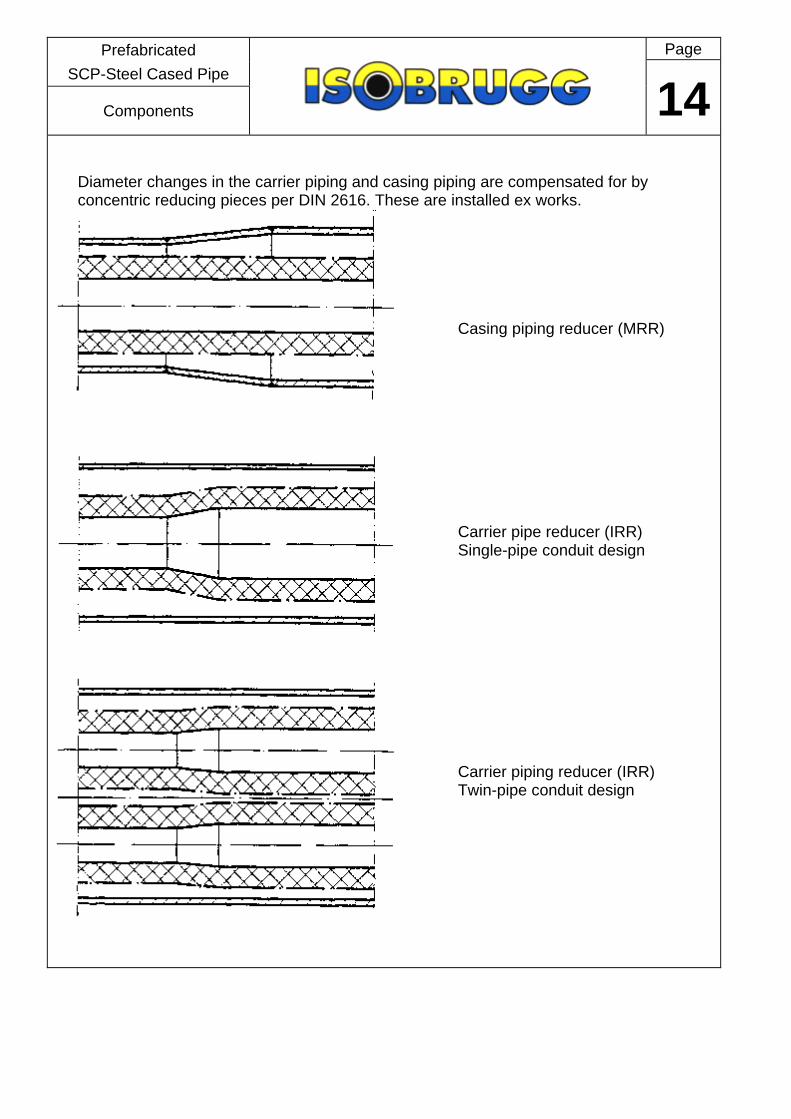
Diameter changes in the carrier piping and casing piping are compensated for by concentric reducing pieces per DIN 2616. These are installed ex works.
Casing piping reducer (MRR)
Carrier pipe reducer (IRR) Single-pipe conduit design
Carrier piping reducer (IRR) Twin-pipe conduit design

Prefabricated
Page SCP-Steel Cased Pipe
15 Components
Kompensator Dehnungselement (KDE)
expansion compensation by internal axial bellows with extended casing pipe
1 Carrier pipe 2 Casing pipe 3 Insolation 4 Axial bellow 5 Track guide 6 corrosion coating 7 Anchor 8 Casing pipe extension

Prefabricated
Page SCP-Steel Cased Pipe
16 Components
Steel shaft with access, designed for an operating loading of up to 60 SLW, in- cluding pump sump, inbuilt ladder, shaft ventilation, corrosion-proofing paint within, exterior corrosion-proofing of reinforced bitumen sheathing in tropical quality per DIN 30673 Type A, 5.5 G with double carrying layer of glass fibre matting, electrical puncture strength 20,000 V, with piping connection pieces for inlet and outlet piping, completely pre- fabricated ex works. Proof of static strength supplied on de- mand. Ballast concrete to hold shafting safely in place is the client’s responsibility.

Prefabricated
Page SCP-Steel Cased Pipe
17 Accessories
When constructing and operating cathodic corrosion-proof equipment, the following pre-conditions must be met: - good electric conductivity throughout; - perfect non-ageing piping sheathing of PE or bitumen without mechanical damage; - the casing piping to be protected must not have any electrical contact to non-system parts or any ancillary installations. Electrical insulation from ancillary low-impedance equipment in shafting or from interconnecting stations of the piping to be protected is carried out by installing insulating flanges. Insulating flanges consist of a flange pair electrically insulated from one another with welding socket ends and internally coated piping supports as insulant. Note that different makers have different designs. Design and installation of cathodic corrosion-proofing equipment for STEEL-CASED distant heat PIPING is part of our service and product range. After installation and commissioning, a metrology protocol on testing and acceptance of the equipment is drafted.

Prefabricated
Page SCP-Steel Cased Pipe
18 Accessories
Cathodic corrosion proofing of STEEL-CASED PIPING Cathodic protection of steel piping laid in the ground is state-of-the art nowadays as active corrosion protection for steel-cased distant heat piping together with passive corrosion protection (PE or bituminous sheathing of the steel-cased piping to DIN standards). This type of plant is required to protect steel-cased piping: 1. in corrosive soil, i.e. where soil resistance values are equal to or less than 10,0000 Ohm cm; 2. in pipelines with greatly varying such values, i.e. differences equal to or larger than 10,0000 Ohm cm; 3. in areas endangered by groundwater, and 4. in areas possibly subject to stray current. Pre-conditions for our guarantee against corrosion of exterior piping protection surfaces Please note DIN 30676, “Planning and use of exterior surface cathodic corrosion protection”. How such equipment functions can be seen in the diagram. The cathodic protective current IS is supplied by a rectifier connected to the mains. The current to the surface to be protected is via an external current anode. This is normally a Fe-Si sited in the earth at a set distance of around 5 m from the piping in a coke bed. The number and arrangement of the Fe-Si anodes depends on the protective current needed and hence on the piping surface to be protected as well as the specific soil resistance. INSULATING FLANGE BRAUNSTAHL insulating flanges are adherent flange connections pre-mounted and tested for electrical penetration resistance as standard. The standard model consists of 2 welding neck flanges, 2 gaskets (flat or O-ring), 1 insulating ring, nuts and bolts, insulating and steel annular discs. Only insulating materials with high electrical pe- netration resistance and good dielectric charac- teristics are used (DIN 7735 standard). O-ring gaskets of non-ageing paracril or other special materials only are used. Metallic materials are selected on the basis of technical conditions of supply or the correspon- ding German and foreign standards and regulati- ons. The standard design requires dis-assembly be- fore welding into the pipeline.

Prefabricated
Page SCP-Steel Cased Pipe
19 Accessories
Pre-condition for the guarantee under our Conditions of Sale is the evacuation of the steel-cased piping by an ISOBRUGG technician. During construction of STEEL-CASED PIPING, atmospheric damp usually penetrates the insulating material and condensate builds up on the casing. Once installation is complete, evacuation of the annular spacing with the aid of a mobile vacuum plant sucks out all the damp in the piping system as a steam-air mixture and the pressure is reduced to around 1 mbar. A pressure increase monitor permits leak rates to be checked constantly and hence inform on whether the system remains leak proof. Apart from these two functions, the heat loss can also be considerably reduced if the distant heating piping is under constant vacuum The mobile vacuum appliance consists of a vacuum pump, a refrigerating machine, a condensator, a fluid collector with automatic rapid emptying and an oil separator. The client must make 380 V AC current and a 32 A Euro plug available to operate the appliance.

Prefabricated
Page SCP-Steel Cased Pipe
20 Accessories
ISOBRUGG Vacuum leat detection with alarm montion Principle sketch of permanent leak detection system

Prefabricated
Page SCP-Steel Cased Pipe
21 Planning
Technical requirements for fabrication Please note: works to be carried out in conjunction with the technical code and the material specification for the fabrication of steel-cased piping and also the rules for installation; codes of practice and rules for civil works such as DIN 18300, DIN 4033, DIN 4124; as well as the rules for the prevention of accidents. All dimensions, especially angular measures, datum's, levels and trench profiles are to be checked prior to commencement of, and during, works. Notify ISOBRUGG immediately in the event of deviations. When crane-handling steel-cased piping, use textile slings only. In order to prevent damage to the external coating, use felt pads at support points during transport and intermediate storage. Only welders holding the RI certificate (DN 8560) or recognised equivalents may be used. Where indicated, carrier pipe is to be cold sprung the required distance as shown on drawing. Transport locking elements may only be removed after aligning and tack welding carrier piping. Within the area of site joints access holes as shown on the civil works data sheet are to be provided prior to laying and backfilling. External coating of each unit is to be Holiday-tested with 25 kV. The SCP units are numbered sequentially and marked accordingly at their ends. Each unit carries the marking, “oben”, denoting the twelve o’clock position. The 12 o’clock position of the carrier piping is marked by a stamped figure “0”. When lining-up the units for welding, both marking must be at the top in the 12 o’clock position.
I RF Einrohrführung Single-pipe conduit II RF Einrohrführung Twin-pipe conduit
CARRIER PIPING Innenrohr Carrier pipe CASING PIPING Mantelrohr Casing PipeIS Isolierdicke Insulation thicknessVL Vorlauf FlowRL Rücklauf ReturnD Dampf SteamK Kondensat CondensateBW Brauchwasser Domestic hot waterZ Zirkulation Circulation
Betriebsdaten: Operating data Betriebsdruck Operating pressure 9 bar Auslegungsdruck Design pressure 25 bar
Operating pressure 14 bar " " " " "Operating pressure 21 bar " " " " "
Temp.- 210 C ( 1 = 2.5 mm/m
LA Axiallager Alignment support ∆ L Innenrohrausdehnung Linear expansion of carrier pipe
LP Lagerplatte Support plate ∆ I Ausdehnungskoeffizient Linear co-effcient of expansion
ZF Zwangsführung Track guide kon Konzentrisch ConcentricFP Festpunkt Intermediate anchor ex. Exzentrisch EccentricMD Mauerdurchführung Wall entry MRR Mantelrohrreduzierung Casing reducer
AKV Axialkomp.-Verschluß Bellow type termination IRR Innenrohrreduzierung Carrier pipe reducer
AK Axialkomp. im Innenrohr Axial Bellow TA T-Zweig T-branch
B Bogen Bend BVS Verschlußkappe(CARRIER PIPING+CASING PIPING) Capped ends
L Linse MS Bellow BE Baueinheit Special unit
BV Baustellenverbindung Site joint
Mantelrohr - Halbschale Casing pipe
makeup piece
Mantelrohr beiziehen Casing pipes abutted

Prefabricated
Page SCP-Steel Cased Pipe
22 Planning

Prefabricated
Page SCP-Steel Cased Pipe
23 Planning
Steel-cased piping selection table single-pipe conduits (IR) Casing pipe sizes for differing temperature ranges dependant on carrier pipe dimensions and thermal insulation (IS) A minimum ring gap of 20 mm is included in the table. Double-check the casing pipe size in the expansion joint areas.

Prefabricated
Page SCP-Steel Cased Pipe
24 Planning
Thermal insulation selection table (standard) Economic thicknesses of mineral wool make-up pieces for various piping dimensions and operating temperatures. Given details of the ground conditions, lambda values for the soil, average soil tem- perature, the dimensions of the carrier and casing piping, medium temperature and corresponding insulation thickness, the heat loss of Isobrugg steel-cased piping can be calculated. For larger projects and lengthier transport piping, especially at high operating tempe- ratures, steel-cased piping systems should be operated with permanent vacuum. The insulation thicknesses in the table can then be reduced without affecting heat loss.

Prefabricated
Page SCP-Steel Cased Pipe
25 Planning
Determination of the casing piping di- mensions in single-pipe conduits(IR) A ring gap of at least 20 mm is essential to ensure the steel-cased piping can be put together easily. The casing piping in-terior diameter must therefore be at least 40 mm greater than the external diame- ter of the thermal insulation. This ring gap is also important to the emptying of the casing piping and the rapid evacua-tion and drying of the thermal insulation as well. At the same time, correct casing piping dimensions tallying with the ring gap size permit carrier pipe movement of at least 2 x 20 mm. Expansion greater than this can only be taken up given lar- ger casing piping.
Determination of the casing piping dimensions Examble: Carrier pipe dimension = DN 150 (168.3 x 4.0)
Carrier pipe temperature = 150 C Insulation thickness per selection table = 70 mm
Casing piping dimensions determination: CARRIER PIPING DN 150 = 168 mm
Insulation 2 x 70 mm = 140 mm Ring gap 2 x 70 mm = 40 mm = 348 mm
Casing piping size to select: DN 350. In the event of directional alteration, longitudinal expansion of the carrier piping is restricted with this choice. These dimensions are applicable for expansion take-up of max. +/- 19.8 mm, totalling 39.6 mm, at 50% pre-stress of the carrier piping. This governs the maximal expansion length (space between anchor and expansion compensators). At a temperature of 150 C, the longitudinal expansion factor = 1.88 mm/m. ∆ L total at 50% pre-stress = Total expansion
Longitudinal expansion factor = 39.6 mm
1.88 mm/m = 21.07 m. This casing piping size is therefore only suitable for short piping distances.
Prefabricated
Page SCP-Steel Cased Pipe
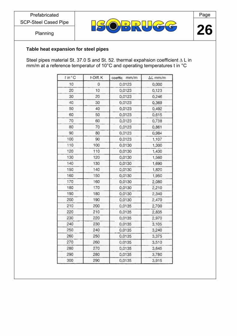
26 Planning
Table heat expansion for steel pipes Steel pipes material St. 37.0 S and St. 52. thermal expahsion coefficient ∆ L in mm/m at a reference temperatur of 10°C and operating temperatures t in °C

Prefabricated
Page SCP-Steel Cased Pipe
27 Planning
Carrier pipe data table seamless steel pipes acc DIN 2448/EN 10216, material St. 37.0 S - Standard

Prefabricated
Page SCP-Steel Cased Pipe
28 Planning
Carrier pipe data table welded steel pipes acc DIN 2448/EN 10217, material St. 37.0 WA or WB, Standard.
WA = welding valmcl 0,9 WB = welding valmcl 1,0

Prefabricated
Page SCP-Steel Cased Pipe
29 Planning
Casing piping table (standard) Casing piping dimensions per DIN 2458/EN 10217 in St. 37.0 WA material - works certification per DIN 50049-2.2 Insofar as thicker walls may be needed for construction engineering reasons, e.g. due to inadequate covering, larger casing piping can be used without hesitation.

Prefabricated
Page SCP-Steel Cased Pipe
30 Planning
One means of increasing expansion length results from the extension of the casing piping in the expansion bend areas. The expansion of casing piping DN 350 to casing piping DN 400 results in an increase in ring gap from 19.8 mm to 45.2 mm and in ex-pansion take-up to a total of 90.4 mm, which means the expansion length can be in- creased to about 40 m instead of the former approximately 20 m. Depending on pipeline profile, casing piping extension of up to four times the dimen- sions is possible, so that carrier piping expansion at 50% pre-stress of up to 200 mm can be compensated for. The natural expansion compensators such as U- Z- and L-bends can also be repla- ced with full-protection bellows-type axial compensators, whereby the normal casing piping usually need not be changed.

Prefabricated
Page SCP-Steel Cased Pipe
31 Planning
Steel-cased piping compensatory expansion elements Insofar as natural expansion compensators such as U-, L- or Z-bends are inadequa- te, bellows-type joints can be substituted. These are also welded to the carrier piping ex works and installed in the steel-cased piping with anchors and guide supports ac- cording to the maker’s regulations. Two expansion elements can be installed in any one special unit, i.e. one intermediate anchor and two compensators with track gui- des as per system diagram can be installed to take up the expansion from both di- rections like a U-bend expansion compensator. With special track guides, bellows- type axial compensators can also be used with twin-pipe conduits. Only so-called “FULLY PROTECTIVE COMPENSATORS” with external protective pi- ping, interior guide tubing, lift limitations devices, pre-stress safety devices, torsion safety devices and their own guide devices are suitable for installation in a steel-ca- sed piping system. The service life of a compensator is dependant on temperature, pressure, load, load change intervals, fluid medium hammering, corrosion and installation errors.

Prefabricated
Page SCP-Steel Cased Pipe
32 Planning

![[PPT]PREFABRICATED BUILDING - Wikispacescarlavl.wikispaces.com/file/view/PREFABRICATED+BUILDING.ppt · Web viewPREFABRICATED BUILDING Vargas, Valentina Vásquez, Carla CONTENT: Prefabricated](https://img.dokumen.tips/doc/110x75/5ada5d397f8b9a6d7e8ca107/pptprefabricated-building-buildingpptweb-viewprefabricated-building-vargas.jpg)