Embed Size (px)
Citation preview

© Faculty of Mechanical Engineering, Belgrade. All rights reserved FME Transactions (2016) 44, 125-132 125
Received: February 2015, Accepted: October 2015 Correspondence to: Dr Ivan Bozic Faculty of Mechanical Engineering, Kraljice Marije 16, 11120 Belgrade 35, Serbia E-mail: [email protected] doi:10.5937/fmet1602125B
Ivan Božić Assistant Professor
University of Belgrade Faculty of Mechanical Engineering
Radiša Jovanović Assistant Professor
University of Belgrade Faculty of Mechanical Engineering
Prediction of Double-Regulated Hydraulic Turbine On-Cam Energy Characteristics by Artificial Neural Networks Approach
The determination of the energy characteristics of a double-regulated
hydro turbine is based on numerous measuring points during extensive and
expensive experimental model tests in the laboratory and on site prototype
tests at the hydropower plant. By the spatial interpolation of representative
measured points that belong to the so-called on-cam curves for different
speed factors, the hill performance diagram is obtained. The focus of the
paper is the contemporary method of artificial neural network models use
for the prediction of turbine characteristics, especially in not measured
operation modes. A part of the existing set of experimental data for the
Kaplan turbine energy parameters is used to train three developed neural
network models. The reliability of applied method is considered by
analysing, testing and validating the predicted turbine energy parameters
in comparison with the remaining data.
Keywords: hydraulic turbine, on-cam characteristics, neural network
1. INTRODUCTION
The determination of the performance hill diagram of a hydro turbine is necessary if its guarantees are based on annual energy production [1]. Hydraulic turbine universal characteristics in the wide operating ranges are obtained by measuring numerous points during extensive experimental tests. The results of those experimental researches are valuable insofar as they are detailed and comprehensive. However, extremely costly both laboratory research on a double-regulated turbine model [2] and on site prototype [3-5] measurements always impose rationalization of conditions in which one turbine would be tested, but not at the expense of quality. For that purpose, the focus of the paper is the contemporary method of the artificial neural networks (ANNs) use for the prediction of turbine characteristics, especially in not measured operation modes.
In recent years, the ANNs have been proposed as an alternative to the physically based models and proven to be very successful in solving complex problems in various engineering fields including industry processes, digital signal processing, pattern recognition, identification, medical engineering, controls, energy modeling and prediction [6-9].
Literature survey shows that there is a relatively small number of published papers regarding the neural networks use in the study of the hydraulic turbine characteristics. A method for modelling of hydro-turbine hill chart with neural network presented in [10] shows that backpropagation neural network model of
hydro-turbine for special discharge and special torque can be used to describe its nonlinear characteristic. In [11], radial basis function neural networks models were established to identify hydropower unit. A neural network expert system for processing fault diagnosis of hydropower unit vibration is presented in [12]. A response surface approach is used for predicting the hill chart of a small horizontal Kaplan turbine based on computational fluid dynamics results [13].
2. TURBINE CHARACTERISTICS, PREDICTIONS
AND LIMITATIONS
The energy performance characteristics of the double-regulated turbine can be generally shown by the following functional dependency:
( , , , , , , , , ,...)GV Rf D Q n H T gη α β ρ= (1)
where: η – efficiency, D – reference diameter, αGV – guide vane angle, βR– runner blade angle, Q – discharge, n – rotational speed, H – net head, T – torque, ρ - water density and g – gravitational acceleration.
The completeness of turbine characteristics can be achieved only if all the influential geometry, energy and cavitation parameters are taken into account. However, the number of independent turbine parameter variables and their mutual functional dependences are such that it is not possible to have their simple graphical or analytical presentation. For this reason, the general dependences are reduced to a greater number of simple dependencies where some turbine performance quantities are, mathematically, the independent parameters whilst functional relations among the other ones are determined [14]. Even though simpler dependencies have significant roles in the hydro power engineering application, they also represent a step in the procedure of forming more complex turbine parameters dependencies - universal energy characteristics.

126 ▪ VOL. 44, No 2, 2016 FME Transactions
Usually, the universal energy characteristic is graphically represented as a three dimensional surface, i.e. as the spatial distribution of turbine dimensionless parameters. In general, such approach is valid for all the other geometrically similar turbines and has invaluable importance.
By considering the specific turbine dimensionless terms, which depend on several variables, it is possible to define the particular influence of each parameter, mutual functions of several variables and an excellent input data base for optimal control system, so relation (1) may become
( , , , )GV R ED EDf Q nη α β= (2)
where 0.5 0.5EDn nDg H
− −= and 2 0.5 0.5EDQ QD g H
− − −=
are speed factor and discharge factor, respectively. To determine on-cam energy characteristics or
performance hill chart of a double-regulated (Kaplan and bulb) turbine, in the first place it is necessary to do thorough off-cam performances measurements. In wide range of various speed and discharge factors, the best efficiency points are reached for several runner blade angles. Then, by the spatial interpolation of such representative measured points that also belong to the so-called on-cam curves (envelope) for different speed factors, the hill performance diagram is made. The more representative points are measured, the more interpolation quality is obtained in order to form the hill chart.
The general formulation of the spatial interpolation problem of turbine efficiencies can be defined as follows: given the N measuring values of a studied parameter η(j) determined at discrete measuring points
( ) ( ) ( ) ( ) ( )( , , , )j GV j R j ED j ED jr Q nα β= , where is j=1, …, N
within a certain region of a 4-dimensional space, find a 4-variate function F(r) which passes through the given points, i.e. fulfills the condition ( ) ( )( )j jF r η= .
Although the previous requirement can be fulfilled by numerous functions, it is necessary to impose additional conditions. Choice of the additional condition, which defines the character of various interpolation techniques, depends on the character of the modelled phenomena. On the other hand, the mathematical form of the law expressing some hydraulic turbine performance quantities that represent physical phenomena is in most cases unknown.
Before the description of the method applied in this paper and its appropriate limitations prescribed by the standard IEC 60193, a brief review of other existing prediction methods is given further below.
2.1 Existing prediction methods
Prior to the age of the mass use of computers, the fitting of the measured and calculated data in order to obtain the hill chart was done manually by the graph-analytical methods. Since then, several available fitting computerized methods according to IEC standard [1] have been based on representation of surfaces. The most frequently applied surface fit categories are: global (polynomial or custom functional form trend surface
and regression-based) and local (inverse distance weighted and regularized and tension splines) deterministic interpolations. Every double-regulated turbine is unique so finding the appropriate fitting methods for its characteristics poses several challenges. Various measured data with different accuracies, which are limited and spatially heterogeneous especially far from optimal sampling, make modeling of characteristics very complex. Interpolation methods based on the classical methods of least squares regression have been used for long, but determination of polynomial coefficients has not always been appropriate for obtaining the best fitted surface passing through the representative measurement points.
The general variational approach to interpolation and approximation is based on the assumption that the interpolation function should pass through (or close to) the data points and be as smooth as possible. These two requirements are combined into a single condition of minimizing the sum of the deviations from the measured points and the smoothness seminorm of the spline function [15]. The regularized and tension splines are the special cases of the variational approach. The former is designed to yield simultaneously good approximations both for the function itself and its derivatives, and the latter admits to tune the smoothness of the interpolant according to the character of the modeled phenomenon [16]. Splines provide enough flexibility for local geometry analysis which is often used as input to various process-based models. Splines rely on a physical model with flexibility provided by the change of elastic properties of the interpolation function [15]. However, performance hill chart as a surface is neither stochastic nor elastic media, but is the result of a host of natural processes so the natural synthesis of both spline types is the regularized spline with tension. One of the newer variational approach prediction methods for mathematical modeling of turbine characteristics is based on the modification and synthesis of Dm-splines and Hardy multiquadric interpolations [17].
However, since the other scientific fields develop spatial interpolation and approximation methods, the same are also applied to the field of hydro turbine performances. Typical examples are the so-called statistical concepts which are based on the interpolation by Kriging. Its main assumption is that the spatial distribution of measuring data can be modeled by a realization of a random function and uses statistical techniques to analyse the data (drift, covariance). The interpolated surface is constructed using statistical conditions of unbiasedness and minimum variance [15]. There are ordinary, universal and simple Kriging methods in which the focus is, respectively, on: the spatially correlated component with the fitted semivariogram use, the spatial drifting variation of values in addition to spatial correlation between sample points and the known means of the data set.
All the previously mentioned different methods, ranging from the manual to the more sophisticated ones, can produce quite different spatial representations. Therefore, their applicability in predicting values of spatial phenomena in unsampled locations (unmeasured conditions) is limited. In order to choose the adequate

FME Transactions VOL. 44, No 2, 2016 ▪ 127
method with appropriate parameters and obtain satisfactory final results of the turbine characteristics, the in-depth knowledge of the phenomenon, experience and specific expertise of users are of great importance. IEC standards [1,18,19] stipulate that the final choice of the interpolation method shall be clearly defined and agreed between the parties concerned. Nevertheless, it should be emphasized that the use of an inappropriate interpolation induces misleading turbine energy characteristics information which lead to wrong decisions about optimal control system input data and to bad calculating of electricity generation efficiency in hydropower plants. 2.2 Recommendations for predicting improvement
according to IEC standard limitations
Prediction tools are reliable and suitable for hydraulic turbine applications if they satisfy the following important requirements: robustness and flexibility in describing characteristics of various types of turbines, accuracy capability, estimation of derivatives and applicability to large datasets. The quality of prediction can be improved if strict recommendations for limitations according to IEC standard are taken into account. Those limitations are related to the number of measuring points, the stability condition of measuring point and the total measurement uncertainty.
For double-regulated turbines the operating conditions and the number of test points are not strictly defined according to IEC 60193, but depend strongly on the purpose of the test, the judgment and experience of the chief of tests, the contractual obligations or agreement of participants in the test. In any case, it is necessary to obtain a sufficient number of points to cover the operation and guarantee ranges. The number of test points shall be always increased if the extended operating range is to be investigated. A greater number of measurement points induces better turbine characteristics prediction, but on the other hand requires more test rig and staff engagement which always reflects in economy of the test. However, if insufficient number of discrete measuring points is taken into account, prediction results may not represent the actual physical phenomenon and real turbine performance hill chart.
The measurement methods applied nowadays result in a relatively small total uncertainty. Depending on the type of measurement, the uncertainty limits are determined by the following standards IEC 60193:1999, IEC 62006:2010 and 60041:1991, the first of which has the strictest criteria. Taking into account the total uncertainties, each measured point can be represented with the minimum (lower) and the maximum (upper) limits of the total uncertainty bandwidth.
During the tests, periodic or random fluctuating of different measured quantities cannot be avoided. Usually, they originate from the parts of the test rig in the laboratory and the turbine assembly at power plant, but also from the effects of the turbulent flows in the studied turbine. Therefore, the smoothening process during characteristics prediction can normally be restricted to averaging measurements at several points
around a given operating point. The condition of measuring point stability is fulfilled if quantities values are within the limits of relative random measurement uncertainty. The proscribed value of this uncertainty in optimal (best efficiency point) operation mode for efficiency, speed and discharge factors is ± 0.3%. These values of total uncertainties are greater in range far from the optimum regime.
Cross-validation is one of the best quantitative evaluation techniques of prediction reliability. The goal of cross validation is to define deviations quality between predicted (unknown, unsampled, unmeasured) values and measured dataset for the same conditions. Normally, such deviations should be within total measurement uncertainty limits. Referent criteria based on [1] are actually applied for cross-validation in the paper.
3. FEEDFORWARD NEURAL NETWORKS (FFNN)
Artificial neural networks (ANNs) method is a computational intelligence technique, which is based on the information processing system of the human brain and which may be used as an alternative method in engineering analyses and predictions. ANNs work as a black-box model and thus it is not necessary to have detailed information about the system. Instead, they learn the relationship between input and output variables by means of historical data, similar to the way a non-linear regression might perform, [6]. The main advantage of an ANN model is its self-learning capability and the ability to approximate a nonlinear relationship between the input variables and the output of a large and complex system. The feedforward neural network architecture consists of an input layer, an output layer, and one or more hidden layers of neurons. Each layer has a number of neurons and each neuron is fully interconnected with adaptable weighted connections to neurons in the subsequent layer. The nonlinear activation functions in the hidden layer neurons enable the neural network to be a universal approximator. The process of training network is the adjustment of the weights, so that the network can produce the desired response to the given inputs. Different training algorithms could be applied to minimize the error function, but the most widely used are the backpropagation algorithm and the algorithms derived from it. They use a gradient descent technique to minimize the cost function which is the mean square difference between the desired and the actual network outputs. In the training process, the cost function is minimized by modifying the weights and biases and this process goes on until the error between the network output and desired output falls below a predetermined value or the maximum number of epochs is exceeded. Generally, backpropagation learning algorithm consists of two phases, i.e., a forward pass and a backward pass, [20]. In the forward pass, a training input vector is presented to the network input layer, and its effect propagates through the network layer by layer until a set of outputs is generated by the output layer as the actual response of the network. During the forward pass, the synaptic weights of the networks are all fixed. On the

128 ▪ VOL. 44, No 2, 2016 FME Transactions
other hand, during the backward pass, the synaptic weights are all adjusted as the error signal is propagated from the output layer to the input layer. Afterwards, the trained ANN can be used for predicting the outputs for the inputs that have not been introduced in the training process. In this study, a multilayer feedforward network with single hidden layer and backpropagation learning algorithm is used.
For the single hidden layer network, the network output in scalar case can be expressed as:
2 1 0 01 1
ˆh n
i ij j i
i j
y f w f w x b b
= =
= + +
∑ ∑ (3)
where the network output ŷ is the predicted value of the variable y, iw and ijw are the weights and 0ib and b0 are
biases. The scalar h denotes the number of neurons in hidden layer and n denotes the number of inputs, while f1 and f2 are activation functions in hidden and output layer, respectively.
4. CASE STUDY
In order to experimentally obtain energy parameters of Kaplan turbine model, detailed researches [22,23] were conducted at the highly sophisticated test rig in the laboratory for hydraulic machinery - LMH (Lausanne, Switzerland). The model of vertical double-regulated turbine is 30.8 times smaller than the existing prototype built in the hydropower plant Iron Gate 1. The high accuracy measurements were carried out for 9 propeller regimes (constant runner blades angles) and for constant eight speed factors. For each runner blade angle, measurements were performed in non-cavitational conditiones for about 15 guide vane angles. From approximately one thousand measurement points, 76 of them which belong to on-cam characteristic surface were chosen. The selected measurement points were used for training and testing the neural network models and for the predicted points validation.
a. ANN model development
The network architecture is generally defined by the number of hidden layer nodes and the number of nodes in each of these layers, and it determines the number of model parameters that need to be estimated. The ANN models used in the experiments are three layer feedforward neural networks composed of one input layer, one output layer and one hidden layer because it has been shown that such a structure can approximate any continuous function of interest with given accuracy, [21]. The input layer contains n neurons used to feed n different inputs into the network (n is a variable because it varies with the proposed models), while the output layer contains one neuron. Since the data size is small, Levenberg–Marquardt training algorithm is adopted. This algorithm as a variant of back-propagation algorithm requires that the activation function used by the artificial neurons be differentiable. Thus, in the hidden layer and the output layer hyperbolic tangent and linear activation functions are used.
The proposed architecture is as shown in Fig. 1, and it consists of three modules, i.e., models. The first model (Model 1) is a neural network whose task is to predict turbine efficiency from the known measurements of βR, αGV, nED and QED as input variables. Model 2 predicts QED according to the input variables: βR, αGV and nED. Guide vane angle αGV prediction by Model 3 is based on βR and nED.
Figure 1. The proposed prediction models
The collected experimental data are used to train and test the proposed neural network models. The first group of the data (65 pairs of observations) is utilized for training the models. The second group of the data (11 pairs of observations) is utilized for testing the model. The criterion for the selection of the second group is such that it covers a wide operating range of turbine, and the 11 points are used only for validation of the predicted results. To ensure that no special factor is dominant over the others, all inputs and outputs are normalized to the interval (0, 1) by a linear scaling function. The NN models’ training starts with a minimum number of elements. The number of these elements is constantly increased and re-training of the NN is continued until satisfactory training is achieved, [Haykin]. For the proposed NN models, the optimum number of neurons in the hidden layer was identified using a trial and error approach. It was found to be 5, 7, and 9 neurons for models 1, 2 and 3, respectively.
Models’ performance can be evaluated through different criteria. In the paper, the root mean square error (RMSE), the mean absolute error (MAE), the mean absolute percentage error (MAPE) and the coefficient of determination (R2) are used.
5. RESULTS AND DISCUSSION
The results of the measured and predicted turbine energy parameters are further on shown as their
normalized values. Normalized values of efficiency *η ,
discharge factors *EDQ and speed factors *
EDn are
determined by converting the absolute values into the
optimal operating point value: *opt/η η η= ,
* /ED ED EDoptQ Q Q= and * /ED ED EDoptn n n= .
The comparison of the measured and the estimated values of efficiencies as well as the relative prediction error, for the training and test data, are shown in Fig. 2 and Fig. 3, respectively. For the above mentioned test rig, the total relative uncertainty of efficiency is ±0.218% at the turbine best efficiency point, which is a pretty rigorous criterion (according to [1], the proscribed

FME Transactions VOL. 44, No 2, 2016 ▪ 129
value of only total relative random measurement uncertainty is ± 0.3%). The error of the predicted
efficiency in optimal operating mode ( 10Rβ = � ,
32.5GVα = � , * 1EDQ = , * 1EDn = ) in relation to the
measuring ones is 0.096% [Fig. 2, sample number 41] which is within the test rig total uncertainty bandwidth.
Figure 2. The prediction results of the Model 1 for training data
Figure 3. The prediction results of the Model 1 for test data
As previously emphasized, values of total uncertainties are greater in range far from the optimum regime. However, the highest error during efficiency prediction, in the mode far from the optimum regime, is 0.37% which is within IEC uncertainty limitation because the recommended bandwidth does not take into account the systematic measurement uncertainty.
Fig. 4 gives the relative deviation for Model 2 both for training and test points determining the discharge factors for the given speed factors and guide vane and runner blades angles.
Figure 4. The prediction errors for the Model 2
Figure 5. The prediction errors for the Model 3
The highest relative error of test points is below 0.1%, which is significantly lower than the predicted relative random error according to [1] which is 0.3%. Relative errors of predicted guide vanes angles based on the Model 3 are shown in Fig. 5. The results of the models evaluation according to the previously mentioned criteria are shown in the Table 1.
Each of the mentioned indices shows that the prediction models are extraordinary and reliable in practice for wide a operating range. Therefore, the proposed models are used to obtain on-cam efficiency
130 ▪ VOL. 44, No 2, 2016 FME Transactions
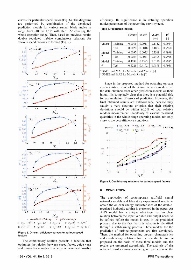
curves for particular speed factor (Fig. 6). The diagrams are performed by combination of the developed prediction models for various runner blade angles in range from -10° to 17.5° with step 0.5° covering the whole operation range. Then, based on previous results double regulated turbine combinatory relations for various speed factors are formed (Fig. 7).
Figure 6. On-cam efficiency curves for various speed factors
The combinatory relation presents a function that optimises the relation between speed factor, guide vane and runner blade angles in order to achieve best possible
efficiency. Its significance is in defining operation modes parameters of the governing servo system.
Table 1. Prediction indices
RMSE*
MAE*
MAPE [%]
R2 [-]
Training 0.0015 0.0011 0.1142 0.9984 Model 1 Test 0.0020 0.0018 0.1862 0.9960
Training 0.0032 0.0025 0.3319 0.9999 Model 2 Test 0.0054 0.0041 0.7405 0.9998
Training 0.4288 0.2585 1.0110 0.9985 Model 3 Test 0.6221 0.4192 1.9898 0.9961
* RMSE and MAE for Models 1 and 2 are in [-] * RMSE and MAE for Models 3 is in [°]
Since in the proposed method for obtaining on-cam
characteristics, some of the neural network models use the data obtained from other prediction models as their input, it is completely clear that there is a potential risk for accumulation of errors of prediction. However, the final obtained results are extraordinary, because they satisfy a very rigorous criterion that their relative deviations should be within ±0.3% of total relative random measurement uncertainty of various measured quantities in the whole range operating modes, not only close to the best efficiency conditions.
Figure 7. Combinatory relations for various speed factors
6. CONCLUSION
The application of contemporary artificial neural networks models and laboratory experimental results to obtain the on-cam energy characteristics of the double-regulated hydraulic turbine is presented in the paper. An ANN model has a unique advantage that no clear relation between the input variable and output needs to be defined before the model is used in the prediction process, due to the fact that this relation is identified through a self-learning process. Three models for the prediction of turbine parameters are first developed. Then, the method for obtaining on-cam characteristics and combinatory relations for the specific turbine is proposed on the basis of these three models and the results are presented accordingly. The analysis of the obtained results shows a rather good prediction of the

FME Transactions VOL. 44, No 2, 2016 ▪ 131
turbine parameters in unknown (unmeasured) operating conditions. The applied method validity is assessed by the comparative analysis of measured and predicted results, as well as by IEC standard prescribed band of their mutual deviations. The proposed methodology, the process of creating individual models and their mutual relations in the procedure of obtaining on-cam characteristics can be used in real engineering practice. The described access has the direct consequence in the rationalization of time, resources and costs necessary to obtain turbine characteristics by expensive model test in highly sophisticated laboratories and complex on site tests. The accuracy of the data also guarantees that this approach is very effective and can be applied to the determination of the relevant input control system data that will contribute to the operation quality of the hydraulic turbines and increased energy efficiencies of the hydropower plants.
REFERENCES
[1] IEC 60193 - Hydraulic turbines, storage pumps
and pump-turbines-Model acceptance tests, International standard, International Electro technical Commission, Geneva, 1999.
[2] Božić, I., Benišek, M.: Experimental and Numerical Analysis of the Kaplan Turbine Characteristics, Full Papers Proceeding of International
Conference „Power Plants 2014“, 28-31.10.2014, Zlatibor, pp. 387-396.
[3] Benišek, M., Božić, I., Čantrak, Đ., Ilić, D.: Hydraulic Tests of the Bulb Turbine Unit at the Hydropower Plant „Djerdap 2“, III International
Symposium Contemporary Problems of Fluid
Mechanics, 12-13.10.2011., Belgrade, pp. 187-194.
[4] Benišek, M., Petrović, D., Božić, I., Ćirić, Z., Damjanović, S., Zeljić, M.: Propeller and combinatory characteristics determination of Kaplan turbine in HPS Zvornik with the aim of increasing its efficiency, Power Plant Symposium
2008, 28-31.10.2008., Vrnjacka Banja
[5] Gajić A., Ignjatović B., Predić Z., Ivljanin B.: Test of Cam Characteristic of the Kaplan Turbine by On-Site Measurement, FME Transactions, Vol.33, Number 3, pp. 145-149, 2005
[6] Kalogirou, S.A.: Artificial neural networks in renewable energy systems applications: a review, Renewable and sustainable energy reviews, Vol. 5, No. 4, pp. 373-401, 2001.
[7] Karatasou S., Santamouris, M., and Geros, V.: Modeling and predicting building`s energy use with artificial neural networks: Methods and results, Energy and Buildings, Vol. 38, pp. 949-958, 2006.
[8] Pham D.T., Liu X., Neural Networks for
Identification, Predication and Control, Springer-Verlag, London, 1995.
[9] Jovanović, R., Sretenović, A. and Živković, B.: Application of artificial neural networks for prediction of heating energy consumption in University buildings, in: Proceedings of the 18th International Research/Expert Conference Trends in
the Development of Machinery and Associated Technology, Budapest, Hungary, 10-12 September, 2014.
[10] Cheng, W., Ye, Y. and Cai, L.: Modeling of hydro-turbine hill chart by neural network, Journal of Huazhong University of Science and Technology Vol. 6, 2003.
[11] Xiao, Z., Wang, S., Zeng, H. and Yuan, X.: Identifying of hydraulic turbine generating unit model based on neural network, in: Proceedings of
the Sixth International Conference on Intelligent
Systems Design and Applications, Vol. 1, pp. 113-117, IEEE, 2006 .
[12] Jia, R., Bai, L., Luo, X. and Liu, F.: Expert system on fault diagnosis based on neural network for hydropower units, Journal of Hydroelectric Engineering, Vol. 6, pp. 120-123, 2004.
[13] Arnone, A., Marconcini, M., Rubechini, F. and Schneider, A.: Kaplan Turbine Performance Prediction Using CFD: an Artificial Neural Network Approach, in: Proceedings of the
Conference HYDRO 2009, Lyon, France, 26-28 October, 2009, Paper 263.
[14] Benisek, M.: Hydraulic Turbines, (in Serbian), Faculty of Mechanical Engineering, Belgrade, 1998.
[15] Mitas, L., Mitasova, H.: General Variational Approach to the Interpolation Problem, Comput. Math. Applic. Vol. 16, No. 12, pp. 983-992, 1988
[16] Mitas, L., Mitasova, H. (1999). Spatial Interpolation. In: P.Longley, M.F. Goodchild, D.J. Maguire, D.W.Rhind (Eds.), Geographical Information
Systems: Principles, Techniques, Management and
Applications, Wiley, pp.481-492, 1999.
[17] Volkov Yu. S., Miroshnichenko V. L., Salienko A. E. Mathematical modeling of hill diagram for Kaplan turbine, (in Russian), Scientific journal Machine Learning and Data Analysis, Vol. 1 (10), pp.1439 – 1450, 2014.
[18] IEC 62006 - Hydraulic machines - Acceptance tests
of small hydroelectric installations, International standard, International Electrotechnical Commi–ssion, Geneva, 2010.
[19] IEC 60041 - Field acceptance tests to determine the
hydraulic performance of hydraulic turbines,
storage pumps and pump-turbines, International standard, International Electrotechnical Commi–ssion, Geneva, 1991.
[20] Haykin, S.: Neural Networks: A Comprehensive
Foundation, 2nd Edition, Prentice Hall, 1998.
[21] Hornik, K., Stinchcombe, M. and White, H.: Multilayer feedforward neural networks are universal approximators, Neural Networks, Vol. 2, pp. 359–366, 1989.
[22] Božić I.: Theoretical and Experimental
Investigation of the Energy Losses Distribution in
the Hydraulic Axial Turbines, (in Serbian), PhD thesis, University of Belgrade, Faculty of Mechanical Engineering, Belgrade, 2012.

132 ▪ VOL. 44, No 2, 2016 FME Transactions
[23] Official Model Test Report – HPP Djerdap 1, test № 535, (March-May 2008), Revised and completed version of Final Report, École Polytechnique Fédérale de Lausanne, Laboratory for Hydraulic Machines, Lausanne, Switzerland, 2011
ПРЕДИКЦИЈА ЕНЕРГЕТСКИХ
КОМБИНАТОРСКИХ КАРАКТЕРИСТИКА
ДВОЈНО РЕГУЛИСАНЕ ХИДРАУЛИЧНЕ
ТУРБИНЕ ПОМОЋУ ВЕШТАЧКИХ
НЕУРОНСКИХ МРЕЖА
Иван Божић, Радиша Јовановић Одређивање енергетских комбинаторских карактеристика двојно регулисане хидрауличне турбине се заснива на резултатима опсежних и
скупих експерименталних испитивања на моделу у лабораторији и теренских мерења на прототипу у хидроелектранама. Експлоатациони дијаграм се добија на основу просторних интерполација репрезентативних мерних тачака које припадају комбинаторским кривама формираних за различите брзинске факторе. У раду је дат акценат на примени савремене методе вештачких неуронских мрежа у одређивању комбинторских карактеристика турбине посебно у радним режимима који нису мерени. Део постојећих података о енергетским параметрима Каплан турбине који су добијени експерименталним путем искоришћени су за обучавање три развијена модела вештачких неуронских мрежа. Анализом, тестирањем и валидацијом добијених енергетских параметара турбине међусобним упоређивањем са осталим експерименталним подацима разматрана је поузданост примeњене методе.