Embed Size (px)
Citation preview

B. SHEN et al. : On Frank-Type Partial Dislocations in Czochralski-Grown Si 321
phys. stat. sol. (a) 155, 321 (1996)
Subject classification: 61.72; 64.75; 72.20; 55.11
Department of Physics and Institute of Solid State Physacs, Nanjang University’) (a) and Institute for Materials Research, Tohoku University, Sendai2) (b)
Precipitation of Cu, Ni, and Fe on Frank-Type Partial Dislocations in Czochralski-Grown Silicon
BY B. SHEN (a), T. SEKIGUCHI (b), R. ZHANG (a), Y. SHI (a), Y. D. ZHENG (a), and K. SUMINO (b)
(Received September 12, 1995)
The segregation behavior of metallic impurities, Cu, Ni, and Fe on Frank-type partial dislocations in Czochalski-grown silicon depends not only on the species of impurities, but also significantly on the cooling rate of the specimen after contamination. In slowly cooled specimens, Cu develops pre- cipitate colonies in the region away from Frank partials and does not decorate them even on an atomic scale, while Ni decorates Frank partials weakly. A high density of Cu or Ni precipitates is observed on Frank partials when specimens are cooled fast. Fe decorates Frank partials both in fast and slowly cooled specimens. The amount of precipitated Fe on Frank partials is larger in a slowly cooled specimen than in a fast cooled one. The difference in segregation behavior on Frank partials among Cu, Ni, and Fe is reasonably interpreted in terms of three parameters: precipitate nuclei as influenced by the dislocation-core structure, crystal structure of precipitates, and diffusivity of im- purities in Si.
1. Introduction
The dominant material used in semiconductor technology is Czochralski-grown silicon (CZ-Si), which contains a high concentration of interstitial oxygen atoms. Various kinds of microdefects are introduced into Si crystals during thermal processing of device fabri- cation due to oxygen precipitation [l, 21. Among them, main defects are extended de- fects, such as bulk stacking faults bounded by Frank-type partial dislocations and punched-out dislocations (perfect edge type). Meanwhile, Si crystals are very easily deco- rated by metallic impurities at high temperatures [3]. Main metallic impurities in Si are Cu, Ni, and Fe because of their high solubilities and diffusivities in Si.
The interaction between metallic impurities and dislocations in Si gives rise to various effects which are extremely important in Si device technology. Dislocations decorated by metallic impurities become electrically active at room temperature, so that they degrade significantly the electrical characteristics of Si devices [4, 51. On the other hand, the segregation behavior of metallic impurities in Si is strongly affected by the presence of extended defects, which gives the physical basis of the “internal gettering” technique used in Si device fabrication [6, 71.
’) Hankon Road, Nanjing 210008, People’s Republic of China. 2 , Sendai 980, Japan.
22%

322 B. SHEN, T. SEKIGUCHI, R. ZHANG, Y. SHI, Y. D. ZHENG, and K. SUMINO
The precipitation behavior of Cu, Ni, and Fe in Si has been studied extensively [8 to 101. However, most works were concentrated on Si crystals free from extended defects, few reports are available about precipitation of metallic impurities in the presence of well-characterized extended defects in Si. Cu precipitation on dislocations in Si was first investigated by Dash et al. [ll, 121. Their results have been widely used as a decoration technique of dislocations in Si crystals. However, these works were performed by means of techniques such as chemical etching or scanning infrared microscopy (SIRM). It was impossible to get information about the interaction between Cu and dislocations in de- tail. Tan and Tice [13] investigated Cu precipitation on punched-out dislocations around oxygen precipitates in CZ-Si and proposed the idea of "internal gettering". However, the mechanism of internal gettering is not yet well clarified until now. An understanding of the mechanism for internal gettering needs further study of the interaction between metallic impurities and extended defects in CZ-Si. Recently, Shen et al. [14] compared Cu precipitation on punched-out dislocations and Frank partials in CZ-Si and found that the precipitation behavior of Cu on these two types of dislocations was very differ- ent. Their results indicate that the type of dislocation and the cooling rate of the speci- men after high-temperature contamination have a strong effect on the precipitation be- havior of Cu in Si.
Since Cu, Ni, and Fe have different solubilities, diffusivities, and atomic sizes in Si [15], their segregation behaviors on extended defects are different from each other. How- ever, few reports to compare their segregation behavior on extended defects have been published until now. It is interesting to clarify how parameters such as the contamina- tion level and the cooling rate of specimens after contamination affect the segregation behavior of Cu, Ni and Fe on extended defects.
Due to its high spatial resolution, the electron beam induced current (EBIC) techni- que is most suitable to study the recombination characteristics on individual extended defects in semiconductors. Because the recombination process on any kind of extended defect in Si is very sensitive to metallic decoration [16, 171, the EBIC technique is a powerful tool to detect the segregation behavior of metallic impurities on individual extended defects. This is especially the case for a low level of metallic decoration which is difficult to be detected with conventional transmission electron microscopy (TEM).
In the present work, we combine EBIC and TEM observations to investigate the pre- cipitation behavior of Cu, Ni, and Fe in CZ-Si crystals. The specimens are dominated by Frank partials. Different segregation behaviors of metallic impurities on Frank partials were discussed on the basis of experimental results.
2. Experimental
The CZ-Si crystal used in this study was n-type, doped with phosphorus, 10 Q cm in resistivity, grown along the [lll] direction, in which the initial oxygen concentration was about 9.0 x 10¹⁷ atoms/cm3.
Specimens were cut from the above Si ingot in the shape of a parallelepiped 1.5 x 6.0 x 10.0mm3 in size with surfaces parallel to (lll), ( l i O ) , and (112) planes. Bulk stacking faults bounded by Frank partials were introduced into the specimens through two-step annealing (750 "C, 15 h + 1000 "C or 1100 "C, 20 h) in Ar. They were a few to several ten pm in diameter with a density of about 1.2 x lo7 or about 8.5 x lo8 cmP3, depending upon the temperature in the second step of annealing. Such

Precipitation of Cu, Ni, and Fe on Frank-Type Partial Dislocations in Si 323
densities and sizes of stacking faults are most suitable for EBIC or TEM observations. Besides stacking faults, punched-out dislocation loops were also observed around some small oxygen precipitates in the specimens. But they were much smaller in size and low- er in density than the stacking faults.
After the above heat treatments, the specimens were contamined with Cu, Ni, or Fe by annealing them together with Cu or Ni at 1000°C or Fe at 1100°C in va- cuum. According to the literature [15], the impurity concentration in the specimens is about 5.0 x 10¹⁷ atoms/cm3 for Cu, 4.0 x 10¹⁷ atoms/cm3 for Ni, and 2.0 x 10¹⁵ atoms/cm3 for Fe. Then, the specimens were cooled from the contamination tempera- ture in ice-water or in air. Specimens cooled by these two procedures are termed F1 or F2. The temperature change during cooling followed an empirical relation approxi- mately given by [HI:
T( t ) - T f = (To - T f ) exp ( -at) , (1)
where To and Tf are the initial and final temperatures in cooling and t the time. The time constant a is about 3.0 and 0.033s-l for F1 and F2, respectively. The average cooling rates of F1 and F2 are about 1600 and 23 K/s, respectively.
Specimens for TEM observation were thinned by means of mechanical polishing fol- lowed by chemical etching. The surface of TEM foils was parallel to the Si (111) plane. TEM observations were performed with a JEOL 2000EX transmission electron micro- scope operated at 200 kV.
EBIC measurements were performed with a TOPCON DS-130 scanning electron mi- croscope (SEM) in an EBIC mode controlled by a computer with an electron beam of 20kV and 1.0nA. The temperature range for EBIC measurements was between 40K and room temperature (290K). The surface of EBIC samples was parallel to the (111) plane. The Schottky contact on the surface was made by means of Au evaporation. The EBIC contrast C of a defect is defined by
C = ( I b - I d ) / I b (2) where I b is the EBIC of the background and I d the EBIC at the location of a defect. The details of this EBIC system are described elsewhere [19].
The concentration of interstitial Fe (Fei) in Fe-contaminated specimens was deter- mined by means of ESR from the intensity of the Fq signal at a magnetic field of 3135 G at 10 K using a continuous flow-type cryostat of Oxford Instruments and a JEOL X-band spectrometer.
3. Experimental Results
3.1 Cu precipitation
A Frank partial bounding a stacking fault free from metallic impurities shows EBIC contrast only at low temperatures but not at room temperature. Its EBIC contrast dis- appears at temperatures between 210 and 250 K as described in [14].
In Cu-contaminated specimens, the EBIC contrast of Frank partials is affected signifi- cantly by the cooling rate of the specimen after contamination. Fig. 1 shows EBIC images of fast and slowly cooled specimens (F1 and F2) at various temperatures. In F2 samples (Fig. 1 a to c), large circles marked by arrows show the contrast of stacking faults on the (111) plane parallel to the specimen surface. Not only Frank partials

324 B. SHEN, T. SEKIGUCHI, R. ZHANG, Y . SHI, Y . D. ZHENG, and K. SUMINO
Fig. 1. EBIC images of Frank partials bounding stacking faults (shown by arrows) at a), d) 50 K, b), e) 110 K, and c), f') 290 K in specimens contaminated with Cu at 1000 "C followed by a) to c) slow cooling (F2) and d) to f) fast cooling (F l )
bounding stacking faults but also fault planes are EBIC-active at low temperatures. The EBIC activity of fault planes will be discussed in a separate paper. The contrast of Frank partials is very strong at 50 K, becomes weaker at 110 K, and disappears at room temperature. Dark contrast of rod-like shape seen in the figure is due to colonies of Cu precipitates. The contrast of the colony increases with increasing temperature.
In F1 samples (Fig I d to f), a Frank partial (shown by an arrow) exhibits EBIC contrast both at low temperatures and room temperature. Other contrasts are from colo- nies of Cu precipitates, which are higher in density and smaller in size in comparison with those in F2.
Fig. 2 shows the temperature dependence of EBIC contrast of Frank partials in a non- contaminated specimen and Cu-contaminated F1 and F2 specimens. The contrast of Frank partials in F2 is almost the same as that in the non-contaminated specimen, both decrease with increasing temperature and disappear at temperatures between 230 and 250 K, indicating that Frank partials are not decorated by Cu in F2. In F1, the contrast of Frank partials increases with increasing temperature and is about 16.1% at room temperature. The temperature dependence of the contrast of Frank partials is very simi- lar to that of Cu precipitate colonies, indicating that Cu precipitation on Frank partials takes place in F1.
Fig. 3 shows TEM micrographs of F1 and F2. No Cu precipitates are observed on a Frank partial in F2 (Fig. 3a). Cu develops large colonies of precipitates in the region away from Frank partials. The colony is a planar arrangement of Cu precipitates in the (110) plane bounded by a perfect edge dislocation loop with Burgers vector a(110)/2.
Precipitation of Cu, Ni, and Fe on Frank-Type Partial Dislocations in Si 325
10 Fig. 2. Temperature dependence of EBIC contrast of Frank partials in a non-contaminated specimen and
8 specimens contaminated with Cu at 1000 "C followed by slow cooling (F2) or fast cooling (Fl)
h
v 8 T I 6 s - g 4
;2 0
0 0 50 100 150 200 250 300
Tern peratu re (K)
The type of the dislocation loop bounding the colony is the same as that of a punched- out dislocation loop generated from an oxygen precipitate. Furthermore, an oxygen pre- cipitate is observed inside the colony. These results indicate that Cu colonies originate from punched-out dislocations.
Fig. 3. TEM micrographs of a) a Cu precipitate colony and a Frank partial in a specimen contami- nated with Cu at 1000 "C followed by slow cooling (F2), and b) Cu precipitates on Frank partials in a specimen contaminated with Cu at 1000 "C followed by fast cooling (Fl)

326 B. SHEN, T. SEKIGUCHI, R. ZHANG, Y. SHI, Y. D. ZHENG, and K. SUMINO
On the other hand, a high density of Cu precipitates is clearly seen along a Frank partial in F1 (Fig. 3b). The shape of the loop which was originally circular is now dis- torted due to the climbing motion of the Frank partial.
3.2 Ni precipitation
Fig. 4 shows EBIC images of Ni-contaminated, fast and slowly cooled specimens (F1 and F2) at various temperatures. The large circles marked by arrows show the contrast of Frank partials. Other contrasts are those from Ni precipitates. In F2 (Fig. 4a to c), a Frank partial exhibits EBIC contrast both at low temperatures and room temperature. But the contrast is very weak at room temperature.
In F1 (Fig. 4d to f), the contrast of a Frank partial is also observed both at low temperatures and room temperature. The contrast in F1 is much stronger than that in F2 at room temperature.
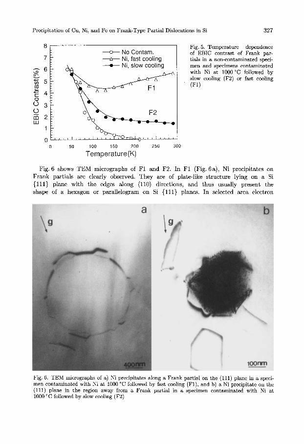
Fig. 5 shows the temperature dependence of EBIC contrast of Frank partials in F1 and F2 specimens. The contrast in F2 decreases with increasing temperature. But different from that in Cu-contaminated F2, it decreases very slowly from 100 K to room temperature, and still keeps about 1.4% at room temperature. In F1, the con- trast first decreases with increasing temperature until about 110 K, which is due to the influence from the contrast of the fault plane, then increases slowly with increas- ing temperature from 110K to room temperature, and attains about 5.6% at room temperature.
Fig. 4. EBIC images of Frank partials (shown by arrows) at a), d) 50 K, b), e) 110 K, and c), f) 290 K in specimens contaminated with Ni at 1000 "C followed by a) to c) slow cooling (F2) and d) to f ) fast cooling (Fl)
Precipitation of Cu, Ni, and Fe on Frank-Type Partial Dislocations in Si 327
8 Fig. 5 . Temperature dependence of EBIC contrast of Frank par-
7 tials in a non-contaminated speci- men and specimens contaminated with Ni at 1000°C followed by - 6 slow cooling (F2) or fast cooling
8 G 5 !I E 4
v
(F1)
6 3 0 a 2 W
1
0
-
0 50 100 150 200 250 300
Te m per at u re (K)
Fig. 6 shows TEM micrographs of F1 and F2. In F1 (Fig. 6a), Ni precipitates on Frank partials are clearly observed. They are of plate-like structure lying on a Si (111) plane with the edges along (110) directions, and thus usually present the shape of a hexagon or parallelogram on Si (111) planes. In selected area electron
Fig. 6. TEM micrographs of a) Ni precipitates along a Frank partial on the (111) plane in a speci- men contaminated with Ni at 1000 "C followed by fast cooling (Fl), and b) a Ni precipitate on the (111) plane in the region away from a Frank partial in a specimen contaminated with Ni at 1000 "C followed by slow cooling (F2)

328 B. SHEN, T. SEKIGUCHI, R. ZHANG, Y. SHI, Y . D. ZHENG, and K. SUMINO
diffraction (SAD) patterns, no spots other than those characteristic of the Si matrix are found.
In F2, no Ni precipitates on Frank partials are observed by means of TEM. But Frank partials exhibit weak EBIC contrast at room temperature as shown in Fig. 4c, we think that very small Ni precipitates difficult to be resolved by means of TEM or atomic state Ni should exist on Frank partials. In the specimen, Ni precipitates of a size from several hundred nm to a few pm are observed in the region away from Frank partials as shown in Fig. 6b. But their density is very low, only about 1.0 x lo6 cmP3. These precip- itates are usually observed in the shape of an octahedron surrounded by Si (111) planes. As in F1, no SAD pattern of Ni precipitates is observed. Ni precipitates are usually accompanied by punched-out dislocation loops around them.
3.3 Fe precipitation
In Fe-contaminated specimens, Frank partials also exhibit EBIC contrast at room tem- perature both in fast and slowly cooled specimens (F1 and F2) as shown in Fig. 7. But different from the case of Ni precipitation, the contrast in F2 is stronger than that in F1 at room temperature. On the EBIC images, besides the circles of Frank partials shown by arrows, other spots are those from Frank partials in other (111) planes or other defects decorated by Fe.
Fig. 8 shows the temperature dependence of EBIC contrast of Frank partials in F1 and F2 specimens. In F2, the contrast first decreases with increasing temperature until
Fig. 7. EBIC images of Frank partials (shown by arrows) a t a), d) 50 K, b), e) 110 K, and c), f) 290 K in specimens contaminated with Fe at 1100 "C followed by a) to c) slow cooling (F2) and d) to f) fast cooling (Fl)

Precipitation of Cu, Ni, and Fe on Frank-Type Partial Dislocations in Si 329
8 Fig. 8. Temperature dependence of EBIC contrast of Frank partials
7 -+- Fe, fast coolin in a non-contaminated specimen and specimens contaminated with Fe at 1100°C followed by slow 6 cooling (F2) or fast cooling (F l )
z 5
r ' 4
u No Contam. h
$?-
v) a C
8 3 0 2 m W 1
100 150 200 250 300 0
0 50
Te m per at u re (K)
about 110 K, which is due to the influence from the contrast of the fault plane, then increases from 110K to room temperature and is about 5.5% at room temperature, which is the highest among Cu-, Ni-, and Fe-contaminated F2. In F1, the contrast of a Frank partial first decreases with increasing temperature until 210 K. This is also due to the influence from the contrast of the fault plane. From 210 K to room temperature, the contrast increases slowly with increasing temperature and is about 3.2% at room tem- perature, which is the lowest among Cu-, Ni-, and Fe-contaminated F1.
In TEM observation, no Fe precipitates or other Fe-related defects on Frank partials or in the Si matrix are observed both in F1 and F2.
Fig. 9 shows the ESR spectra of Fei in Fe-contaminated F1, F2, and an as-grown specimen (no heat treatment for oxygen precipitation to introduce extended defects), which was contaminated with Fe at 1100 "C and fast cooled. The peak intensity of Fei
. . . .
. . . . . .
. _ . . . . i :
i : . .. . . . . . . .... CZ-Si
F2 - F1 _ _ - - _ _ -
1 , 1 1 1 1 1 1 1 1
3120 3140 3160
Magnetic Fie ld(G)
Fig. 9. ESR signals of intersititial Fe (Fei) in an as-grown CZ-Si crystal contaminated with Fe at 1100°C followed by fast cooling and specimens contaminated with Fe at 1100 "C followed by slow cooling (F2) or fast cooling (Fl) after heat treatment for defect introduc- tion

330 B. SHEN, T. SEKIGUCHI, R. ZHANG, Y. SHI, Y. D. ZHENG, and K. SUMINO
in the as-grown specimen is stronger than those in F1 and F2, indicating that Fe precip- itation on Frank partials has taken place both in F1 and F2. But the peak intensity in F1 is stronger than that in F2. This means that the concentration of Fei in F1 is higher than in F2. In other words, the amount of precipitated Fe atoms on Frank partials in F2 is larger than in F1.
4. Discussion
From the above experimental results, we find that the segregation behavior or metallic impurities on Frank partials depends not only on the species of impurities but also sig- nificantly on the cooling rate of the specimen after contamination.
In a specimen cooled slowly, Cu develops precipitate colonies in the region away from Frank partials and does not decorate them even on an atomic scale. Cu colonies origi- nate from punched-out dislocation loops although they are much lower in density and smaller in size in comparison with Frank partials. We think that two factors favor Cu precipitation on punched-out dislocations.
The first factor is that Cu precipitation on punched-out dislocations takes place under lower supersaturation of Cu than that on Frank partials. If Cu precipitates on a disloca- tion, the potential barrier for the nucleation of Cu atoms in terms of classical nucleation theory is reduced in the strain field of a dislocation [20]. The free energy of the nuclea- tion is proportional to the square of the Burgers vector of the dislocation. Since the magnitude of the Burgers vector of a perfect edge dislocation is larger than that of a Frank partial by a factor of m, the gain in the potential barrier in the strain field of the perfect edge dislocation is larger than that of the Frank partial. Therefore, punched- out dislocations are more efficient nucleation sites for Cu atoms.
However, only this factor is not sufficient since punched-out dislocation loops are much lower in density and smaller in size than Frank partials in the specimen. The second factor is the repeated nucleation process of Cu precipitats on the dislocation in Si, which has been investigated by Seibt [8] and Solberg et al. [21].
Because the phase of Cu precipitates in Si has been suggested to be a low-temperature polymorph of Cu3Si [22], which is a Cu-rich silicide, Cu precipitation in Si is accompa- nied by a very large volume expansion [22, 231. The repeated precipitation of Cu in- cludes at least three basic processes: 1. nucleation of a Cu precipitate at some pre-exist- ing dislocation, 2. growth of the precipitate resulting in the emission of Si interstitials (Sii) to relax the volume expansion which forces the dislocation to climb, 3. unpinning of the dislocation followed by the nucleation of a new Cu precipitate.
In a slowly cooled specimen (F2) , Cu first precipitates on small punched-out dislocation loops during cooling and forces them to climb by absorbing Sii which are emitted from Cu precipitates. Then, the growing loops provide more nucleation sites for new Cu precipi- tates as the specimen is cooled. Since the cooling rate is low enough, the growing loops can absorb most of the supersaturated Cu during the cooling. As a consequence, the supersat- uration of Cu necessary to nucleate precipitates on Frank partials is never attained. There- fore, Cu develops precipitate colonies and does not precipitate on Frank partials.
In a fast cooled specimen (Fl), the high cooling rate leads to sufficiently high super- saturation of Cu to nucleate precipitates on Frank partials as well as on small punched- out dislocation loops. Therefore, both Cu precipitation on Frank partials and the forma- tion of Cu colonies take place.

Precipitation of Cu, Ni, and Fe on Frank-Type Partial Dislocations in Si 33 1
In the case of Ni precipitation, the most important difference from Cu precipitation is that Frank partials exhibit EBIC contrast at room temperature in F2 although the con- trast is very weak, indicating that Ni can decorate Frank partials and change their recombination activity in F2.
The phase of Ni precipitates in Si is Nisi2 [24]. The cubic CaF2 structure of Nisi2 has the lattice parameter 0.5406 nm which is very similar to that of the diamond cubic unit cell of Si (0.5428 mm) [9, 241. Thus, Ni precipitates form a very well matched epitaxial structure with the Si matrix along (111) directions and no SAD pattern of Ni precipi- tates is observed [25]. In this case, only a limited number of Sii are involved in Ni pre- cipitation in Si.
In a slowly cooled specimen (F2), Ni first nucleates on small punched-out dislocation loops since punched-out dislocations are also more efficient nucleation centers for metal- lic impurities than Frank partials. However, small punched-out dislocation loops cannot grow through the climb motion by absorbing Sii like in the case of Cu precipitation. Thus, they cannot provide nucleation centers to absorb all the supersaturated Ni atoms as the specimen is cooled. With the decrease of temperature, the diffusivity of Ni de- creases, some of the Ni atoms far from punched-out dislocations precipitate on Frank partials near them. Therefore, although most of Ni atoms precipitate on punched-out dislocations, Ni can decorate Frank partials. Because Ni atoms are gettered by Frank partials at low temperatures in cooling, Ni precipitates on Frank partials, if they exist, are very small, and cannot be resolved by means of TEM. But the EBIC contrast along the Frank partial in F2 is not uniform at room temperature as shown in Fig. 4c, indicat- ing that small Ni precipitates exist on Frank partials.
In a fast cooled specimen (Fl), since the high cooling rate leads to much higher super- saturation of Ni than that in F2, Ni begins to nucleate on Frank partials at higher temperature in comparison with that in F2 during cooling. Therefore, Ni precipitates of a high density are observed on Frank partials. The situation is similar to that in Cu- contaminated F1.
In the case of Fe precipitation, Frank partials also exhibit EBIC contrast both in fast and slowly cooled specimens. However, different from Ni precipitation, the contrast in F2 is stronger than that in F1. On the other hand, no Fe precipitates or other Fe- related defects on Frank partials or in the Si matrix are observed by means of TEM.
The solubility of Fe is much lower than those of Cu and Ni in Si. For instance, the solubility of Fe at 1100 "C is only about 2.0 x lOI5 atoms/cm3, while that of Cu is about 1.0 x 10'' atoms/cm3 [15]. Therefore, Fe precipitates on Frank partials or in Si matrix, if present, should be very small, and thus cannot be resolved by means of conventional TEM.
Meanwhile, Fe atoms also have much lower diffusivity than Cu or Ni atoms in Si. For instance, the diffusivity of Fe at 1000 "C is about 2.0 x cm2/s, while that of Cu is about 1.0 x lop4 cm2/s [15]. In Fe-contaminated specimens, even if punched-out disloca- tions are more efficient nucleation sites for Fe than Frank partials like for Cu or Ni, the slow diffusion limits the relaxation of supersaturation of Fe through its precipitation on punched-out dislocations as the specimen is cooled. During cooling, Fe atoms only precip- itate on the defects within their diffusion distance, which is much shorter than that of Cu or Ni. In other words, the key parameter to determine the precipitation behavior of Fe in Si is the diffusion constant of Fe rather than the strength of the interaction be- tween Fe atoms and individual dislocations. Therefore, Fe more easily decorates Frank partials in F2 in comparison with Cu or Ni.

332 B. SHEN et al.: On Frank-Type Partial Dislocations in Czochralski-Grown Si
On the other hand, because the diffusion distance of Fe in F1 is shorter than in F2 during cooling, more Fe atoms are frozen at the interstitial sites in F1. Thus, the amount of precipitated Fe atoms on Frank partials in F1 is less than in F2.
5. Conclusion
The precipitation behavior of Cu, Ni, and Fe on Frank partials in CZ-Si depends not only on the species of metallic impurities, but also significantly on the cooling rate of a specimen after contamination. In slowly cooled specimens, Cu develops precipitate colo- nies in the region away from Frank partials and does not decorate them even on an atomic scale, while Ni decorates Frank partials weakly. A high density of Cu or Ni precipitates are observed on Frank partials when specimens are cooled fast. Fe decorates Frank partials both in fast and slowly cooled specimens. Furthermore, the amount of precipitated Fe on Frank partials is larger in a slowly cooled specimen than in a fast cooled one.
The difference in segregation behavior on Frank partials among Cu, Ni, and Fe impu- rities is reasonably interpreted in terms of 1. precipitation of metallic impurities on punched-out dislocations under lower supersaturation of impurities than on Frank par- tials, 2. the repeated precipitation of Cu, which does not take place for Ni due to the different crystal structures of Cu and Ni precipitates, 3. the lower diffusivity of Fe than those of Cu or Ni, which promotes the Fe decoration of Frank partials.
References
[l] S. M. Hu, J. Vacuum Sci. & Technol. 14, 17 (1977). [2] F. SHIMURA, Semiconductor Silicon Crystal Technology, Academic Press, San Diego (CA) 1989. [3] D. GILLES and H. EWE, in: Semiconductor Silicon 1994, Ed. H. R. HUFF, W. BERGHOLZ, and
[4] V. HIGGS, E. C. LIGHTOWLERS, C. E. NERMAN, and P. KNIGHTLEY, Mater. Sci. Forum. 83/87,
[5] T. S. FELL, P. R. WILSHAW, and M. D. DE COTEAU, phys. stat. sol. (a) 138, 695 (1993). [6] K. V. WVI, Imperfections and Impurities in Semiconductor Silicon, Academic Press/Wiley,
[7] D. GILLES, E. R. WEBER, and S. HAHN, Phys. Rev. Letters 64, 196 (1989). [8] M. SEIBRT, Solid State Phenom. 19/20, 454 (1991). [9] M. SEIBT and W. SCHROTER, Phil. Mag. A59, 337 (1989).
[lo] A. G. GULTS and L. E. KATZ, Phil. Mag. 30, 1419 (1974). [ll] W. C. DASH, J . appl. Phys. 27, 1193 (1956). [12] W. C. DASH, Phys. Rev. Letters 1, 400 (1958). [13] T. Y. TAN and W. K. TICE, Phil. Mag. 34, 615 (1976). [14] B. SHEN, T. SEKIGUCHI, J . JABLONSKI, and K. SUMINO, J. appl. Phys. 76, 4540 (1994). 1151 E. R. WEBER, Appl. Phys. A 30, 1 (1983). 1161 V. HIGGS, M. GOULDING, A. BRINKLEW, and P. KIGHTLEY, Appl. Phys. Letters 60, 1369 (1992). [17] P. R. WILSHAW, T. S. FELL, and M. D. DE COTEAU, J . Physique (IV) 1, C6-3 (1991). [18] H. TAKAHASHI, Doctor Thesis, Tohuko University (Japan), 1994. 1191 T. SEKIGUCHI, S. KUSANAGI, Y. MIYAMURA, and K. SUMINO, Acta phys. Polon. A 83, 71 (1993). [20] J. W. CAHN, Acta metall. 5, 169 (1957). [21] J. K. SOLBERG and E. NES, J . Mater. Sci. 13, 2233 (1978). [22] J. K. SOLBERG, Acta cryst. A34, 684 (1978). [23] M. SEIBT and W. SCHROTER, Solid State Phenom. 19/20, 283 (1991). [24] D. CHERNS, G. R. ANSTIS, J . L. HOTCHISON, and J. C. H. SPENCE, Phil. Mag. A46, 849 (1982). [25] P. D. AUGUSTUS, Inst. Phys. Conf. Ser. No. 67(4), 21 (1983).
K. SUMINO, Electrochem. SOC., Pennington 1994 (p. 772).
1309 (1992).
New York 1981.