Embed Size (px)
Citation preview

Pre-selection and Design Services for Thermal Hydrolysis Process System for the North End Sewage Treatment Plant Section 11355 City of Winnipeg Page 1 of 41 RFP #866-2016. December 2016
THERMAL HYDROLYSIS PROCESS SYSTEM
1. GENERAL
1.1 Summary
This Section covers the work necessary for the design, manufacture, supply, delivery, .1installation assistance, training, testing, commissioning, and guaranteed performance testing of a Thermal Hydrolysis Process System (THPS). All equipment, excluding the process gas unit will be installed indoors, within a new THP building. The process gas unit will be installed outside within a separate enclosure.
The systems that supply feedstock to the THPS, and the ancillary systems are critical parts .2to the operation of the THPS and must be fully integrated into the design of the THP. The pre-dewatering system, sludge storage, THPS feed pumps, and digester feed pumps will be provided by the Design Builder.
Responsibility and Scope of Supply: .3
.1 Provide a complete THPS, including all accessories and appurtenances.
.2 The System shall include but not be limited to:
.1 THPS reactors and vessels.
.2 Interconnecting sludge, water, gas and steam piping, including all necessary fittings and valves within the THP skid or module. Piping will extend to boundary of the skid, terminating in flanges for the interconnection of piping installed by the Design Builder.
.3 THP reactor recirculation pumps and fittings (if required).
.4 Process gas system skids including condensing/cooling systems, all safety and regulating valves, instruments and controls, and flanged connections to piping provided by the Design Builder. The process gas system skids will be installed outdoors, in a separate enclosure provided by the Design Builder.
.5 Control systems complete with all accessories and appurtenances, including main control panels, instruments and devices directly connected to equipment within the scope of supply or on equipment skids, pneumatic tubing, airsets, instrument air piping within the boundary of the skids, and connections at the skid boundary for interconnection by the Design Builder.
.6 Electrical wiring within the boundary of the skids, with terminations at junction boxes, for connection to the NEWPCC’s electrical power supply by the Design Builder.
.7 Safety systems including pressure/vacuum relief valves, pressure safety valves, emergency stops/pullcords for each piece of equipment, etc.
.8 Steam feed lances and control valves.
Pre-selection and Design Services for Thermal Hydrolysis Process System for the North End Sewage Treatment Plant Section 11355 City of Winnipeg Page 2 of 41 RFP #866-2016. December 2016
THERMAL HYDROLYSIS PROCESS SYSTEM
.9 Insulation and recovery jackets.
.10 Testing
.11 Structural components including supporting framework, anchoring systems, service platforms, handrails, staircases etc. that fit within the boundaries of the equipment skids.
.3 Provide all components and accessories of the System to enhance ease of operation and maintenance, and as necessary to place the equipment in operation in conformance with the specified performance, features and functions.
.4 The THPS Supplier is responsible for the THP vessel design including all layouts, 3D models, structural calculations for support platforms and structures, and vessel material and sizing.
.5 The THPS Supplier is responsible for the design of interconnecting piping and valves supplied and pre-assembled as part of the THPS package (on skid piping or piping that is part of a module), including supporting structure and pipe supports, and stress analysis and expansion/contraction design for all piping 100 mm in diameter or greater.
.6 The THPS Supplier will also review the design and installation of the upstream dewatering system, polymer system, steam generation system, feed and discharge pumps, and ancillary systems to be designed and provided by others to ensure that they are acceptable to the THPS Supplier.
.7 Instrumentation and Controls must meet the requirements of the City of Winnipeg Water and Waste Department Automation Design Guide.
.8 Electrical equipment and wiring must meet the requirements of Division 16.
1.2 References
Reference Codes and Standards: The design, manufacture, and installation of the THPS must .1meet or exceed the applicable provisions and recommendations of the following codes and standards authorities:
.1 SPPA: C.C.S.M. c. S210 The Steam and Pressure Plants Act
.2 ABMA: American Bearing Manufacturers Association
.1 ABMA 9, Load Ratings And Fatigue Life For Ball Bearings
.2 ABMA 11, Load Ratings And Fatigue Life For Roller Bearings
.3 AGMA: American Gear Manufacturers Association
.4 AISC: American Institute of Steel Construction
.1 Manual of Steel Construction.
Pre-selection and Design Services for Thermal Hydrolysis Process System for the North End Sewage Treatment Plant Section 11355 City of Winnipeg Page 3 of 41 RFP #866-2016. December 2016
THERMAL HYDROLYSIS PROCESS SYSTEM
.2 Specification for the Design, Fabrication, and Erection of Structural Steel for Buildings.
.5 ANSI: American National Standards Institute
.6 API: American Petroleum Institute
.1 API STD 520, Sizing, Selection, and Installation of Pressure-relieving Devices
.2 API STD 521, Pressure-relieving and Depressuring Systems
.3 API STD 620, Design and Construction of Large, Welded, Low-pressure Storage Tanks
.7 ASME: ASME International (formerly American Society of Mechanical Engineers)
.1 ASME/BPVC Section V, Nondestructive Examination
.2 ASME/BPVC Section VII, Recommended Guidelines for the Care of Power Boilers
.3 ASME/BPVC Section VIII-1, Division 1 Rules for Construction of Pressure Vessels
.4 ASME/BPVC Section VIII-2, Division 2 Alternative Rules - Rules for Construction of Pressure Vessels
.5 ASME/BPVC Section IX, Qualification Standard for Welding, Brazing, and Fusing Procedures; Welders; Brazers; and Welding, Brazing, and Fusing Operators - Welding, Brazing and Fusing Qualifications
.6 ASME B31.1, Power Piping
.7 ASME B31.3, Process Piping
.8 ASME B40.100, Pressure Gauges and Gauge Attachments
.9 ASME B40.200, Thermometers, Direct Reading and Remote Reading
.8 ASTM: ASTM International (formerly American Society of Testing and Materials)
.1 ASTM A193/A193M, Standard Specification for Alloy-Steel and Stainless Steel Bolting for High Temperature or High Pressure Service and Other Special Purpose Applications
.9 AWS: American Welding Society
.1 AWS D1.1: Structural Steel Welding Code
.2 AWS D1.6: Structural Welding Code – Stainless Steel
.3 AWS QC1: Standard for AWS Certification of Welding Inspectors
Pre-selection and Design Services for Thermal Hydrolysis Process System for the North End Sewage Treatment Plant Section 11355 City of Winnipeg Page 4 of 41 RFP #866-2016. December 2016
THERMAL HYDROLYSIS PROCESS SYSTEM
.10 CSA: Canadian Standards Association
.1 CSA B149.1 Natural Gas and Propane Installation Code.
.2 ANSI/CSA B149.6: Code for Digester Gas, Landfill Gas, and Biogas Generation and Utilization
.3 CSA B51: Boiler, Pressure Vessel, and Pressure Piping Code
.4 CSA C22.1, Canadian Electrical Code, Part I Safety Standard for Electrical Installations
.5 CSA W47.1: Certification of Companies for the Fusion Welding of Steel
.6 CSA W59: Welded Steel Construction (metal arc welding)
.7 CSA W178.1: Certification of Welding Inspection Organizations
.8 CSA W178.2: Certification of Welding Inspectors
.11 FM: Factory Mutual Research.
.12 IEC: International Electrotechnical Commission
.1 IEC60079 Series: Explosive Atmospheres
.13 IEEE: Institute of Electrical and Electronics Engineers.
.14 ISA: Instrument Society of America.
.1 ISA Tr 12.24.01, Recommended Practice for Classification of Locations for Electrical Installations Classified as Class I, Zone 0, Zone 1, or Zone 2
.2 ISA 12.01.01, Definitions and Information Pertaining to Electrical Equipment in Hazardous (Classified) Locations
.15 ISO: International Organization for Standardization
.16 National Fire Code of Canada
.17 NACE: NACE International (formerly National Association of Corrosion Engineers)
.1 NACE SP0178, Design, Fabrication, and Surface Finish Practices for Tanks and Vessels to Be Lined for Immersion Service
.18 NEMA: National Electrical Manufacturers Association.
.19 NFPA: National Fire Protection Association.
.20 NLGI: National Lubricating Grease Institute.

Pre-selection and Design Services for Thermal Hydrolysis Process System for the North End Sewage Treatment Plant Section 11355 City of Winnipeg Page 5 of 41 RFP #866-2016. December 2016
THERMAL HYDROLYSIS PROCESS SYSTEM
.21 Occupational Safety and Health Act (OSHA).
.22 Underwriters Laboratories Inc. (UL).
.23 Underwriters Laboratories of Canada (ULC).
.24 SMACNA: Sheet Metal and Air Conditioning Contractors' National Association.
.25 All local laws and ordinances.
1.3 Abbreviations
The following is a list of abbreviations which may be used in this Section: .1
.1 DS: Dry Solids
.2 GPT: Guaranteed Performance Test
.3 HMI: Human-Machine Interface
.4 HS: Hydrolyzed Sludge
.5 H2S: Hydrogen Sulphide.
.6 LCP: Local Control Panel
.7 MCP: Main Control Panel
.8 PCS: Process Control System
.9 PDPFS: Pre-dewatered primary fermented sludge
.10 PCN: Process Control Narratives
.11 PDS: Pre-dewatered Sludge (undigested).
.12 PDWAS: Pre-dewatered waste activated sludge
.13 P&ID: Piping and Instrumentation Diagram
.14 PLC: Programmable Logic Controller.
.15 PS: Primary Sludge
.16 SIS: Safety Instrumented System
.17 TEW: Treated Effluent Water
.18 TFS: Thickened Fermented Primary Sludge
.19 THPS: Thermal Hydrolysis Process System

Pre-selection and Design Services for Thermal Hydrolysis Process System for the North End Sewage Treatment Plant Section 11355 City of Winnipeg Page 6 of 41 RFP #866-2016. December 2016
THERMAL HYDROLYSIS PROCESS SYSTEM
.20 TPS: Thickened Primary Sludge
.21 TSS: Total Suspended Solids.
.22 TWAS: Thickened Waste Activated Sludge.
.23 WAS: Waste Activated Sludge.
1.4 Materials, Workmanship and Quality Assurance
The THPS Supplier will fabricate, pre-assemble, and test the equipment provided under this .1Section in their fabrication shop to the extent possible and as required for shop testing. The THPS Supplier will then disassemble and make the equipment ready for shipment for installation and reassembly by the Design Builder on site.
This Section directs attention to certain features, but does not purport to cover all details .2entering into the design of the equipment. Design all parts to have adequate strength and durability to ensure that the equipment performs in accordance with the requirements of the Contract.
Confirm material and equipment complies with the latest edition of the applicable standards in .3force at the time of tendering. In the case of a conflict between this Section and any standards, the more stringent of the two shall apply.
Provide materials and equipment as follows: .4
.1 New and of the highest quality. Reconditioned equipment is not acceptable.
.2 Suitable for the service intended.
.3 Selected and fabricated with an equipment design life exceeding 20 years
Design machinery such that all working parts are readily accessible for inspection and repair, .5and each part is suitable for the service required.
Design equipment to have adequate strength, power and capacity for both continuous and .6intermittent service.
Equipment Tag Numbers: As specified in the City of Winnipeg Tag Naming Standard .7(Appendix A), all items of equipment, piping, and piping accessories will be identified by a tag number. These tag numbers will be assigned by the Design Builder and should be used throughout the project as a unique identifier for the equipment and information associated with that equipment.
1.5 Submittals
Submittals must be made in accordance with Section 01330. Shop Drawings, Submittals for .1Information Only, Other Documents for Review, catalogue cuts, samples, and other material required to completely describe and specify the System and equipment must be submitted for review based on the requirements of Section 01330.
Pre-selection and Design Services for Thermal Hydrolysis Process System for the North End Sewage Treatment Plant Section 11355 City of Winnipeg Page 7 of 41 RFP #866-2016. December 2016
THERMAL HYDROLYSIS PROCESS SYSTEM
Provide the Submittals in two stages - an initial Submittal including all process data, Shop .2Drawings for mechanical, and structural elements and a second submittal including the remainder of the Shop Drawings, Other Submittals for Review, Submittals for Information Only, draft O&M Manuals, Training Plans and Training Materials for the complete scope of supply within the time specified in these specifications..
With the Submittals, provide a copy of the Technical Specifications marked up to reflect any .3revisions, additions, or deletions. Summarize any revisions, additions, or deletions in an attached document, clearly identifying the revision, addition, or deletion, and including an explanation. Include detailed explanation on the function of the process, performance of the process, interfacing equipment or Systems, and utility requirements.
For the Initial Submittal, provide the following Shop Drawings: .4
.1 General arrangement drawings showing the layout of the THPS, including dimensions. Include a plan view of the THPS and elevation/section views from the side and from the front of the THPS. As a minimum, also provide drawings for the following:
.1 All primary units of mechanical and electrical equipment showing outside dimensions.
.2 All maintenance and access platforms.
.3 Process piping and ductwork with diameter or maximum cross-section dimension of greater than or equal to 100 mm in double line format and piping and tubing less than 100 mm in single line format.
.4 Locations for all interfaces with process, structural, mechanical, and electrical and controls equipment supplied under other packages, including clearly identified tie-in points.
.5 Isometrics and 3D models, AutoCAD DWFx format (2014) of the THPS, including spool sheets for the piping.
.2 A detailed schematic process flow diagram (PFD) of the System to fully illustrate interconnection of equipment, location of critical monitoring and control instrumentation and to describe the functionality of the process. The process flow streams in the diagram must be cross referenced to the heat and mass balance summary to completely describe the process.
.3 A complete list of equipment, including primary equipment design criteria, proposed manufacturer's name and model number, and shipping and operating weights (when full). Append and cross reference equipment catalogue descriptions to the equipment list, where applicable.
.4 A summary of utility requirements for total System operation, including steam requirements (during start-up, normal, and peak conditions), wash water/flushing water, and instrument air. This summary must be based on the same conditions as the heat and mass balances described in this Section. Itemise utility requirements for each equipment component and list peak volumetric flow rate (L/s), maximum month, and
Pre-selection and Design Services for Thermal Hydrolysis Process System for the North End Sewage Treatment Plant Section 11355 City of Winnipeg Page 8 of 41 RFP #866-2016. December 2016
THERMAL HYDROLYSIS PROCESS SYSTEM
annual average demands (m3/h), design and operating pressures (kPa), and design and operating temperatures (°C).
.5 Materials of construction for major components.
.6 Outline drawings and specifications of all major items of equipment to be supplied showing all dimensions, parts, weight, and construction details and materials.
.7 Detailed drawings showing safety systems to be employed.
.8 Complete piping and instrumentation diagrams (P&IDs) using AutoDesk Smart P&IDs (2014). The P&IDs must graphically describe the process, the flow streams, the major equipment, and the control method. Show and label each pump, instrument, valve, line, and other similar item.
.1 The P&ID must accurately represent the relative position of equipment and control sensors within the process network so that the purpose and the operating ranges can be determined. Optionally, identify flow quantities and temperatures at appropriate points on the P&ID to clarify the process.
.2 Electrical interlocks and control functions must be represented by standard symbols on the P&ID.
.3 All equipment, valves, lines, and instruments and programming must use the City of Winnipeg’s tagging system.
.9 Process control narratives (PCN) to complement the P&IDs.
.1 Overview: Describe the goals and intent of each unit process within the THPS.
.1 The overview must provide a functional description of the process, including key operating parameters, control schemes, and interfaces to the PCS. The description must include the purpose of, and process reactions expected from each control device for all modes of operation, including reactions to fault conditions.
.2 The description must also include all manual actions required of the Plant operator. Automatic operations must be clarified as to discrete (ON/OFF or step) type actions and analog (proportional or gradual) type actions.
.2 Detailed Description: Describe in detail the monitoring and control functions of each unit process within the THPS.
.1 The detailed descriptions must provide definition of all interlocks, alarms and permissives.
.2 Define all dependent steps required for start-up, shutdown, and the consequences of out-of-sequence operator action. Describe start-up and shutdown steps for both the entire System and for select components of the System (eg. one reactor vessel).
Pre-selection and Design Services for Thermal Hydrolysis Process System for the North End Sewage Treatment Plant Section 11355 City of Winnipeg Page 9 of 41 RFP #866-2016. December 2016
THERMAL HYDROLYSIS PROCESS SYSTEM
.3 Describe adverse operating conditions and define operator action for each adverse operating condition.
.4 Address all possible process fault conditions.
.5 Indicate the extent of automatic and manual control action required for fail-safe reactions to fault conditions.
.6 Define all the requirements for process interlocks with the rest of the process.
.3 PCNs to be updated and provided after Commissioning with all commissioning settings and modifications, as part of the final submittals.
As part of the Second Submittal provide the following additional Shop Drawings: .5
.1 Locations and details of any sampling stations directly mounted to equipment in this Contract.
.2 Locations and details of all drain and vent connections.
.3 Piping less than 12 mm diameter may be shown in a schematic form for initial submission purposes. Actual routing drawings for piping less than 12 mm diameter are required for final Shop Drawings.
.4 A finish schedule and colour schedule for equipment, piping, and structural steel members.
.5 A schedule, or graphic, that delineates all piping and ductwork materials to be used in the System, by service. This submittal must include, as a minimum, size, material with grade designations, operating pressure and temperature, test pressure and test type (pneumatic or hydrostatic), insulation thickness and type, and recovering/jacketing to be used.
.6 A valve schedule that indicates for each valve: the valve number, service, the valve type, size, manufacturer and model/series number, and temperature/pressure ratings. In addition, catalogue information fully describing the materials of construction and manufacturer's service requirements must be submitted.
.1 For all actuated valves, include torque requirements, actuator type, fail position, stroke time, and limit switch details (where appropriate).
.2 For all actuated valves, include actuator catalogue information, tubing diagrams and wiring diagrams.
.3 For self-contained automatic valves (pressure/vacuum relief, pressure reducing, backpressure sustaining, etc.), include catalogue information describing materials of construction and manufacturer's service requirements. Include information describing pilot devices, tubing, and other attachments as necessary.
.4 For self-contained automatic valves, include in the valve schedule the adjustable range and initial factory set point of the valve.
Pre-selection and Design Services for Thermal Hydrolysis Process System for the North End Sewage Treatment Plant Section 11355 City of Winnipeg Page 10 of 41 RFP #866-2016. December 2016
THERMAL HYDROLYSIS PROCESS SYSTEM
.7 For the welding of pressure vessels and steel and stainless steel piping and ductwork, the following welding submittal information must be provided:
.1 Submit all documentation necessary to validate that piping and pressure vessels, including the completed Systems, comply with ASME, S P P A , a n d Manitoba Labour requirements for fabrication shop inspection, shop testing, quality control, and certification; for the services required for the piping, pressure vessels and complete Systems.
.2 Where the T H P S Supplier has obtained certification from ASME and has the National Board of Boiler and Pressure Vessel Inspectors Registration provide proof of ASME and National Board of Boiler and Pressure Vessel Inspectors documentation.
Provide the following Submittals for Information Only: .6
.1 Detailed heat and mass balance summary and basis of design for the complete THPS based on the requirements of this Section. Provide drawings stamped by an Engineer licensed in the Province of Manitoba. Base the heat and mass balance on conditions specified below in this Section under Design Conditions. Include, at a minimum, the following:
.1 Dry solids mass rates, total wet mass (dry solids and moisture) rates, percent dry solids concentrations, temperatures, and pressures for each process, recycle, discharge and exhaust stream.
.2 Heating and fuel requirements (natural gas and steam flows), including maximum design and operating temperatures and pressures.
.3 Cooling water requirements, itemized for each point of usage within the System, including flow rates, temperature, pressure, and quality of cooling water supply and cooling water discharge streams.
.4 All System exhaust gas flow rates, temperatures, pressures, density and quality, including H2S, methane and oxygen concentrations.
.2 The heat and mass balances to be submitted and displayed graphically, using a flow schematic of the THPS to display the figures. In addition, utility system requirements must be displayed. The following units must be used:
.1 For solid material flows:
Mass flow rate kilograms per day of dry material (kgDS/d) Solids concentration percent dry solids (%DS) Volumetric flow rate cubic metres per hour (m³/h) Temperature degrees Celsius (°C) Pressure (gauge) kiloPascals (gauge) (kPa(g)) Enthalpy mega joules per tonne (MJ/t) Heat flow/power mega joules per day (MJ/d) and kilowatts (kW)

Pre-selection and Design Services for Thermal Hydrolysis Process System for the North End Sewage Treatment Plant Section 11355 City of Winnipeg Page 11 of 41 RFP #866-2016. December 2016
THERMAL HYDROLYSIS PROCESS SYSTEM
For liquid flows: Mass flow rate kilograms per day (kg/d) Volumetric flow rate litres per second (L/s) or cubic metres per hour
(m³/h) Temperature degrees Celsius (°C) Pressure (gauge) kiloPascals (gauge) (kPa(g)) Enthalpy mega joules per tonne (MJ/t) Heat flow/power mega joules per day (MJ/d) and kilowatts (kW)
.2 For gaseous flows (biogas, process gas, air):
Mass flow rate kilograms per hour (kg/h) Volumetric flow rate normal and actual cubic metres per hour (Nm³/h,
m³/h). Normal (standard) conditions are defined as 1 atmosphere pressure and 15°C. Relative humidity is 0 percent.
Temperature degrees Celsius (°C) Pressure (gauge) kiloPascals (gauge) (kPa(g)) Enthalpy mega joules per tonne (MJ/t) Heat flow/power mega joules per day (MJ/d) and kilowatts (kW)
.3 For air flows:
Mass flow rate kilograms per hour (kg/h) Volumetric flow rate normal and actual cubic metres per hour (Nm³/h,
m³/h). Normal (standard) conditions are defined as 1 atmosphere pressure and 15°C.
Temperature degrees Celsius (°C) Pressure (gauge) kiloPascals (gauge) (kPa(g)) Enthalpy mega joules per tonne (MJ/t) Heat flow/power mega joules per day (MJ/d) and kilowatts (kW)
.4 For steam flows:
Mass flow rate kilograms per hour (kg/h) Volumetric flow rate cubic metres per hour m3/h expressed as cold
water equivalent (CWE) Temperature degrees Celsius (°C) Pressure (gauge) kiloPascals (gauge) (kPa(g)) Enthalpy mega joules per tonne (MJ/t) Heat flow/power mega joules per day (MJ/d) and kilowatts (kW)
Pre-selection and Design Services for Thermal Hydrolysis Process System for the North End Sewage Treatment Plant Section 11355 City of Winnipeg Page 12 of 41 RFP #866-2016. December 2016
THERMAL HYDROLYSIS PROCESS SYSTEM
.3 Pressure Vessels: In addition to Product Data and Shop Drawings, submit vessel calculations stamped and sealed by an Engineer licensed in the Province of Manitoba and provide certifications and test reports as required by the applicable codes.
.4 Stress analysis results and expansion/contraction design for skid mounted piping 100 mm in diameter or greater stamped and sealed by an Engineer licensed in the Province of Manitoba.
.5 A preliminary safety assessment of the System (for use in the HAZOP), summarising hazard potential and mitigation measures included in the design.
.6 A list of all certification requirements for operation and maintenance of the THPS in the Province of Manitoba. Certification requirements shall be specific to Manitoba as determined by the Office of the Fire Commissioner, Water and the Wastewater Facility Operators Regulation 77/2003, and any other applicable Provincial requirements.
.7 Safety Plan, prepared by the THPS Supplier, addressing equipment and features incorporated into the design, control attributes, and procedures to be followed for start-up, shutdown, normal operation, and emergency shutdown conditions including power failure, to assure a safe working environment for the THPS.
.8 Structural calculations for support structures for all equipment, piping and appurtenances, and for all access platforms, elevated walkways, stairs, and landings stamped by an Engineer licensed in the Province of Manitoba.
.9 Anchor bolt design calculations stamped by an Engineer licensed in the Province of Manitoba.
.10 A description, including narrative and drawings (where necessary), of equipment hoisting and maintenance access required. This description must include a summary plan for the maintenance and removal/replacement of all major equipment items. Hoisting and maintenance access to be provided by the Design Builder. Coordinate with the Design Builder.
Electrical Shop Drawings: .7
.1 Motor starters and VFDs will be provided by the Design Builder
.2 Provide sufficient electrical loading information to allow for sizing electrical distribution equipment, motor starting equipment and power cabling to power the proposed Systems and equipment.
.3 Electrical load list.
.4 Plan drawings showing locations of all equipment, devices and control panels.
.5 Interior layout drawings for electrical and instrumentation panels.
.6 Layout drawings for all electrical, instrumentation and controls cables.
.7 Recommended list of equipment that requires emergency or standby power.
Pre-selection and Design Services for Thermal Hydrolysis Process System for the North End Sewage Treatment Plant Section 11355 City of Winnipeg Page 13 of 41 RFP #866-2016. December 2016
THERMAL HYDROLYSIS PROCESS SYSTEM
Instrumentation and Control Shop Drawings: .8
.1 Control system architecture drawings depicting layout and location of hardware and communication interfaces.
.2 Technical information and descriptive data for all instruments and control devices provided under this Supply Contract.
.3 For the digital based control system provide I/O and memory mapping and detailed operating description consisting of flow charts that describe the functionality of the programmed logic.
.4 Provide digital control system hardware information depicting component layout drawings including terminal wiring schematics, I/O addressing, I/O rack/card assignments, and complete Bill of Materials.
.5 Provide digital control systems software information in the form of program files and Human Machine Interface (HMI) development files. In addition, provide a spreadsheet with a database listing tag names, data type, units, ranges or states, text description and memory location of all system data elements.
1.6 Operations and Maintenance Manuals
Provide Operations and Maintenance Manuals for the Systems specified herein as specified .1in Section 01330 organized with the information specified in Section 01735. Also include:
.1 Manual specifically written for the THPS provided in accordance with these documents and including detailed process operating instructions, start-up and shutdown procedures, process control and troubleshooting procedures, all emergency procedures, and safety procedures.
.2 The THPS Supplier will provide all information necessary for the Design Builder to compile an overall Operations Manual for the NEWPCC Upgrade. Refer to the City of Winnipeg Operations Specifications Content Pages in Appendix B for an indication of the information that must be provided to the Design Builder by the THPS Supplier.
.3 The approved safety plan in a separate tabbed section of the manual.
.4 Recommended settings for all automatic control functions.
.5 A set of complete as-approved information, and as-built electrical, instrumentation, and control wiring diagrams.
.6 Descriptive data and operating characteristics of all electrical and control equipment including; equipment ratings, testing and adjustment information, troubleshooting procedures, final devices settings or programmed features, programming manuals, Shop Drawing information updated to site record information and any other information required for operating and maintaining the devices or systems.
.7 A listing of all I/O points, with definitions, electrical characteristics, state conditions and ranges as appropriate.

Pre-selection and Design Services for Thermal Hydrolysis Process System for the North End Sewage Treatment Plant Section 11355 City of Winnipeg Page 14 of 41 RFP #866-2016. December 2016
THERMAL HYDROLYSIS PROCESS SYSTEM
.8 A map of internal tag and registers to be made available for integrators to read from and/or write to, as appropriate, via the PCS.
.9 A copy of final programs and program listings in native device format on hard media that can be used to reload the programs on the device(s).
.10 An index of all equipment suppliers, listing current names, addresses, and telephone numbers of those who should be contacted for service, information, and assistance.
.11 Test certificates and warranty certificates from all manufacturers.
.12 Local authorities' inspection, approval and acceptance certificates.
.13 As-fabricated drawings.
1.7 Spares
.1 Spare parts are to be supplied by the THPS Supplier and are intended to include all parts which normally would be required within the first two (2) years of operation for normal preventative maintenance and where fabrication requirements for special parts would delay delivery and could keep an item of equipment out of service for an extended period.
.2 Identify any special spare parts not provided above with a price list.
.3 In addition, provide a list of all spare parts, not including lubricants, which normally would be required through the first five (5) years of operation. Indicate expected replacement interval for each part listed and provide prices and expected delivery times.
1.8 Quality Assurance
Compatibility and Integration .1
.1 To ensure compatibility and integration, the design and installation of feed systems and ancillary systems supplied by others must be reviewed by the THPS Supplier. These systems include as a minimum:
.1 Pre-dewatered WAS and fermented primary sludge system including centrifuge feed tanks and associated pumps, centrifuges, centrate tanks and pumps, polymer system, dilution water System, THPS feed pumps, and digester feed pumps.
.2 Steam Supply System.
.3 Hydrolysed Sludge Cooling System.
Supply equipment free from defect in design, manufacture, workmanship and materials. .2
1.9 Safety
The THPS must comply with all Standards and Codes of Practice in Canada and Manitoba. .1
Pre-selection and Design Services for Thermal Hydrolysis Process System for the North End Sewage Treatment Plant Section 11355 City of Winnipeg Page 15 of 41 RFP #866-2016. December 2016
THERMAL HYDROLYSIS PROCESS SYSTEM
A safety plan must be produced and submitted, demonstrating compliance and demonstrating .2that the principles of designing for safety have been followed.
An overall HAZOP Study must be completed during the design phase of the THPS. As a .3minimum the process, electrical and I&C Engineers from the THPS Supplier must attend, along with representatives from the City, and Design Builder. The HAZOP Study will be held in the City of Winnipeg.
As part of the HAZOP a SIL (Safety Integrity Level) and LOPA (Layers of Protection .4Analysis) is required.
A HAZOP facilitator will be selected and paid for by the City of Winnipeg. .5
The THPS Supplier will provide the P&IDs and models for the equipment under their scope .6of supply. The Design Builder will provide the rest of the P&IDs and models for the complete System.
After the HAZOP, refinements to the System to provide safe working environment are the .7responsibility of the THPS Supplier to incorporate at no additional cost.
1.10 Warranty
Submit warranties for each specific piece of equipment or component in accordance with .1these specifications.
Provide Process Guarantee. .2
2. PRODUCTS
2.1 Description
The THPS will hydrolyse a blend of pre-dewatered waste activated sludge (PDWAS) and .1pre-dewatered primary fermented sludge (PDPFS). The combination of PDWAS and PDPFS is referred to as pre-dewatered sludge (PDS).
A dewatering system will be installed upstream of the THP, which will include but not limited .2to, centrifuge feed tanks (receiving TWAS and FPS), centrifuge feed pumps, centrifuges, a dewatered sludge collection storage and conveyor system. The dewatering system will be supplied by the Design Builder.
THPS feed pumps will distribute the feed sludge to the THPS. The dewatering system and .3THP feed pumps will be supplied by the Design Builder.
The THPS will thermally hydrolyze the delivered PDS, converting it to Hydrolyzed Sludge. .4The function of the THPS is described in this Section.
The HS pumps will pump the thermally HS into the digesters. The HS pumps will be .5supplied by the Design Builder.

Pre-selection and Design Services for Thermal Hydrolysis Process System for the North End Sewage Treatment Plant Section 11355 City of Winnipeg Page 16 of 41 RFP #866-2016. December 2016
THERMAL HYDROLYSIS PROCESS SYSTEM
2.2 Function of the THPS
The THPS will be located upstream of mesophilic anaerobic digestion and final dewatering. .1The sludge from the final dewatering process will be at approximately 30 percent solids concentration for land application, soil manufacturing, and/or landfill reclamation.
The THPS must be a complete system designed for the sole function of hydrolyzing PDS. .2The HS will achieve the following benefits:
.1 Reduce viscosity, allowing the downstream mesophilic anaerobic digestion to be operated at higher solids concentrations reducing the required number of digesters.
.2 Enhance anaerobic digestion performance in terms of solids destruction and biogas yield.
.3 Enhance dewaterability of the digested sludge reducing overall polymer use, sludge storage and disposal costs.
.4 Produce a sludge that meets the time and temperature requirements for pathogen requirements for Class A product as defined by Title 40 of the Code of Federal Regulations (CFR) Part 503, Subpart D.
To heat the contents of the THP reactors, directly inject live steam. Incorporate steam .3recycling within the THPS to minimise live steam requirements. Design the THPS to operate efficiently in terms of electrical power and steam consumption.
Provide arrangements to bypass individual pressure vessels to allow a vessel to be taken .4out of service for annual inspection, as per code requirements, while maintaining System operation with the remaining equipment, operating at maximum month flow conditions.
2.3 Equipment Standardization
The City of Winnipeg has standardized on specific electrical and automation manufacturers. .1The Electrical and Instrumentation Standardization Summary (Appendix C) provides a list of the equipment that has been standardized.
It is the City of Winnipeg’s preference that the equipment listed in The Electrical and .2Instrumentation Standardization Summary be used in the THPS. However, if in the opinion of the THPS Supplier there is a technical or safety reason that the standardized equipment should not be used, the THPS Supplier shall include in their proposal justification for using an alternative, and provide a solution for communication with the rest of the automation system.
The Supplier shall provide a solution to address changes to the Suppliers system over the .3life of the THPS. This includes the potential for the control system to become obsolete or unsupported. Provide an outline describing how replacement parts can be integrated seamlessly over a series of technological upgrades.
2.4 Materials of Construction
Reactors and Pressure Vessels: Material to be suitable for the intended use. .1
Pre-selection and Design Services for Thermal Hydrolysis Process System for the North End Sewage Treatment Plant Section 11355 City of Winnipeg Page 17 of 41 RFP #866-2016. December 2016
THERMAL HYDROLYSIS PROCESS SYSTEM
Miscellaneous Metals: Grating and checker plantes to anodized aluminum. Structural metal .2framing to be stainless steel, aluminum or galvanized steel.
Anchor Bolts, nuts, threaded components: 316 Stainless Steel. .3
Control panels: .4
.1 Provide control panels in accordance with Division 16 and the City of Winnipeg Water and Waste Department Automation Design Guide.
2.5 Redundancy
Provide N+1 redundancy at maximum month flow conditions as defined in this Section for THP .1reactors.
Provide redundancy for all vessels such that if one tank is out of service, the THPS can remain .2in operation at maximum month flow conditions with the remaining tanks in service.
Provide all recirculation/feed and other process pumping within the THPS with at least 100% .3capacity redundancy.
Design the THPS with redundancy for the complete System as supplied, including vessels, .4pumps, ancillary equipment, piping, valves, instruments, controls and connections, such that if any one unit, item, section of pipe or connection is out of service, the THPS can remain in operation at maximum month flow conditions.
2.6 Design Conditions
Ambient Conditions .1
.1 North End Sewage Treatment Plant THP Building Grade Elevation: 231.6 m.
.2 Atmospheric Pressure: average 98.54 kPa.
.3 Ambient Temperatures:
.1 Design Max: 35°C
.2 Design Min: - 35°C
2.7 Room Conditions
Design Max: 35°C .1
Design Min: 5°C .2
Maximum relative humidity: 100 percent .3
Minimum relative humidity: 15 percent .4
Maximum ambient sulphide concentrations: 1 ppm .5
Pre-selection and Design Services for Thermal Hydrolysis Process System for the North End Sewage Treatment Plant Section 11355 City of Winnipeg Page 18 of 41 RFP #866-2016. December 2016
THERMAL HYDROLYSIS PROCESS SYSTEM
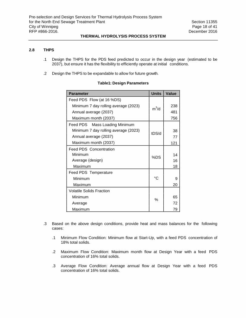
2.8 THPS
Design the THPS for the PDS feed predicted to occur in the design year (estimated to be .12037), but ensure it has the flexibility to efficiently operate at initial conditions.
Design the THPS to be expandable to allow for future growth. .2
Table1: Design Parameters
Parameter Units Value Feed PDS Flow (at 16 %DS)
m3/d
Minimum 7 day rolling average (2023) 238 Annual average (2037) 481 Maximum month (2037) 756 Feed PDS Mass Loading Minimum
tDS/d
Minimum 7 day rolling average (2023) 38 Annual average (2037) 77 Maximum month (2037) 121 Feed PDS Concentration
%DS
Minimum 14 Average (design) 16 Maximum 18 Feed PDS Temperature
°C
Minimum 9 Maximum 20 Volatile Solids Fraction
%
Minimum 65 Average 72 Maximum 79
Based on the above design conditions, provide heat and mass balances for the following .3cases:
.1 Minimum Flow Condition: Minimum flow at Start-Up, with a feed PDS concentration of 18% total solids.
.2 Maximum Flow Condition: Maximum month flow at Design Year with a feed PDS concentration of 16% total solids.
.3 Average Flow Condition: Average annual flow at Design Year with a feed PDS concentration of 16% total solids.

Pre-selection and Design Services for Thermal Hydrolysis Process System for the North End Sewage Treatment Plant Section 11355 City of Winnipeg Page 19 of 41 RFP #866-2016. December 2016
THERMAL HYDROLYSIS PROCESS SYSTEM
2.9 Sludge Cooling (By Design Builder)
The thermally hydrolyzed sludge will be cooled using heat exchangers prior to being sent to .1anaerobic digestion.
The sludge must be cooled to a temperature suitable for mesophilic anaerobic digestion. .2
The THPS Supplier will provide all cooling requirement information to the Design Builder. .3
2.10 Utilities Service Conditions (By Design Builder)
The THPS Supplier will provide all utility system information requirements (quality and .1quantity) to the Design Builder.
Provide tie-in connections for all utility systems, clearly identified, including, steam, treated .2effluent water, process gas, instrument air, electrical and communication services, drains, etc. that serve the THPS. Clearly identify these tie-in conditions on the drawings.
2.11 Area Classifications: mechanical, electrical, instrumentation and control equipment in the process areas of the THP building is considered unclassified relative to Class 1, Group D. Instruments in direct contact with the sludge or the headspace above the sludge must be rated for Class 1, Group D, Division 2.
2.12 Pressure Vessels
Pressure vessels to be designed, fabricated, tested and code stamped in accordance with the .1latest edition of Section VIII, Division 1, Pressure Vessels of ASME Boiler and Pressure Vessel Code and addenda and must meet Province of Manitoba Code requirements. A Canadian Registration Number (CRN) is required for each pressure vessel.
Design pressure vessels rated for maximum hydrostatic test pressure as per the ASME Boiler .2and Pressure Vessel Code Section VIII and full vacuum.
Flanges to comply with ASME B16.5. .3
Where required, provide properly installed blind flanges, corrosion resistant, selected for the .4intended service, securely tightened using Type 316 stainless steel spiral wound gaskets and ASTM A193/A193M G r a d e B8M bolts.
Provide top and bottom skirts as required for stiffening and support with access openings and .5pipe penetrations, as required, including drain holes and drain piping at low points.
Include manways, with davit and handle bars for easy removal, minimum 900 mm diameter, .6one at a low point in each vessel and a second hatch 900 mm in diameter on the roof or side of each vessel near the top.
Insulate vessels as required to minimize heat loss and for thermal protection. .7
Nozzles to penetrate a minimum of 150 mm into the vessel unless otherwise indicated. .8
Pre-selection and Design Services for Thermal Hydrolysis Process System for the North End Sewage Treatment Plant Section 11355 City of Winnipeg Page 20 of 41 RFP #866-2016. December 2016
THERMAL HYDROLYSIS PROCESS SYSTEM
2.13 Steam
Provide steam quantity, quality and operating conditions at all throughputs, including peak .1instantaneous steam demand (defined as the load required to heat all the reactors required to treat maximum month throughput), durations (including short term surges), steam use patterns, reliability requirements (i.e how long can the THPS sit in “hold” mode without steam, and any other operating constraints.
All steam piping (by THPS Supplier on equipment skids and by Design Builder for .2interconnecting piping) to meet the code requirements of ASME and Province of Manitoba.
Provide the necessary monitoring elements and transmitters to measure and report to the .3THP control system and the Schneider based PLC control system, the mass flow, temperature and pressure of the steam to the THPS and calculate and record cumulative mass flow and daily average temperature and pressure in the THP control system.
2.14 Process Gas System
Any process gases arising from the THPS must be treated and returned to the THPS or digester .1headspace. Venting process gas directly to atmosphere is not acceptable as part of normal operations.
2.15 Pressure/Vacuum Relief Valves (PVRVs)
Provide relief valves capable of relieving pressure and vacuum on the pressure vessels. .1
Equip the inlet side of all safety valves, which otherwise would be in constant or intermittent .2contact with sludge and particulate, with rupture discs. Provide pressure indication between rupture disks and PVRVs, including transmission to the local control system.
Mount PVRVs on the roof of each pressure vessel. .3
Emergency venting of process gas into the interior of the THP building is not acceptable. .4
PVRVs on pressure vessels to meet ASME steam safety valve requirements and SPPA .5certification requirements as well as API 520 and API 521 code requirements.
Provide full-bore valves designed to meet maximum venting requirements, clearly marked .6with correct pressure settings, readily accessible for testing and recertification.
Select materials resistant to organic gases at a pH between 2.0 and 7.0. .7
2.16 Metal Work
Provide all platforms, stairways, handrails, anchor bolts, and ladders as required, to provide .1convenient and safe access to all areas of equipment requiring maintenance or access to instrumentation.
Maintenance platforms must allow maintenance personnel access to equipment drive .2systems, lubrication points, sample points, valves, relief valves, instrumentation, and other equipment items commonly requiring attention, within reasonable and safe reach for a
Pre-selection and Design Services for Thermal Hydrolysis Process System for the North End Sewage Treatment Plant Section 11355 City of Winnipeg Page 21 of 41 RFP #866-2016. December 2016
THERMAL HYDROLYSIS PROCESS SYSTEM
person on the platform, and must not require additional stools or ladders for work to be performed.
Platforms located in areas where wet material is handled, around sample points, and around .3material transfer points must incorporate tray sections to prevent material from falling through to the floor level below.
2.17 System Equipment and Appurtenances
General: .1
.1 Provide all other equipment and appurtenances required for a complete package that meets the criteria of this Section.
.2 Select all equipment for type and function and size the equipment to accomplish the performance requirements specified herein.
.3 Material of Construction: Materials to be resistant to corrosion and suitable for the anticipated operating conditions, for a design service life minimum of 20 years.
Bearings: All rotating equipment antifriction bearings must be rated for a minimum ABMA 9 .2and/or ABMA 11 L10 life of 100,000 hours.
Coupling guards must meet The Workplace Safety and Health Act (Manitoba) requirements. .3
Thermal Expansion Provisions: Design the THPS with all necessary provisions to .4accommodate the effects of thermally induced movement and stress on all parts of the THPS. The provisions must allow operation of the THPS under all normal and abnormal upset thermal conditions and must prevent overstressing the THPS materials of construction and excessive movement of THPS components.
Sampling Points: .5
.1 Permanent sampling provisions must be provided for the sampling of the following materials in the general locations indicated:
.1 PDS feed to the THPS at the inlet to the pulper tank or reactors.
.2 HS output from the THPS.
.3 Additional sampling points as recommended by the THPS Supplier to monitor performance, and as required during testing and commissioning.
.2 Provide flushing connections and proper drains for sampling points.
.3 Provide sampling locations with easy access, arranged in a manner that is safe for the operator and minimises or eliminates material leakage and/or spillage while sampling is conducted.
Pre-selection and Design Services for Thermal Hydrolysis Process System for the North End Sewage Treatment Plant Section 11355 City of Winnipeg Page 22 of 41 RFP #866-2016. December 2016
THERMAL HYDROLYSIS PROCESS SYSTEM
Grounding: All equipment, piping, and ductwork must be electrically continuous and attached .6to a grounding conductor. Internal components of equipment must be static conducting and connected to the equipment grounding conductor.
Fail-Safe Provisions: .7
.1 Make provisions for safe operating and shutdown conditions in the event of power failures and equipment failures.
.2 Include automatic controls to shut off valves and gates to prevent uncontrolled sludge, steam, gas, or liquid flow. On loss of power, ensure valves fail to a safe position that prevents unsafe conditions or equipment damage.
.3 Design the System to provide safe failure mode. This will be reviewed and confirmed during the HAZOP.
2.18 Equipment Lifting and Removal
Provide individual hoists, lifting hooks and roof anchors or lifting beams on the underside of .1the platform mounted directly over each component as an integral part of the supplied skids or modules as required to enable each component to be lifted and removed to a suitable laydown area.
Lifting Lugs: Provide lifting lugs or other provisions for easy handling on all equipment and .2removable parts weighing over 40 kg.
2.19 Piping, Ductwork and Valves
General: .1
.1 All piping, piping supports, miscellaneous piping appurtenances, and valves for the THP skids or modules must meet ASME and SPPA requirements. Route and install piping so as to provide headroom and easy access to all process components and instruments. Deliver skids or modules pre-piped. Extend piping to the boundary of the skid terminating in flanges for the connection of interconnecting piping installed by the Design Builder.
.2 The Design Builder will provide all necessary interconnecting piping, piping support systems, miscellaneous piping appurtenances, and valves required to connect skids/modules to other skids/modules or equipment to provide a complete and operable System.
.3 Use standard long radius elbows for all sludge piping except PDS piping. Use 3D elbows for all PDS piping.
.4 Design piping to accommodate thermal displacement. Conduct stress analysis and expansion/contraction design on all piping systems 100 mm in diameter or greater.
.5 Design piping supports to handle thrust, gravity, dynamic forces, and seismic forces.
Pre-selection and Design Services for Thermal Hydrolysis Process System for the North End Sewage Treatment Plant Section 11355 City of Winnipeg Page 23 of 41 RFP #866-2016. December 2016
THERMAL HYDROLYSIS PROCESS SYSTEM
.6 Provide each piece of equipment having a baseplate or other drainage connection with a piping connection extending from the baseplate or other drainage connection to allow for tie-in by the Design Builder.
.7 Welding procedures for stainless steel piping must comply with ASME and SPPA requirements.
2.20 Valves
Provide manual valves and pneumatic operated valves. Select valves in conformance with .1ASME and SPPA requirements.
Provide self-contained automatic valves, solenoid valves, and valves for modulating service .2sized to meet the process requirements and installed where necessary to provide a complete and functional System.
Provide isolation valves at all process equipment connections to allow for maintenance. .3Include spectacle blinds in addition to the isolation valves as a means of double blocking on tank connections where personnel access is required in accordance with Manitoba Occupational Health and Safety Code requirements.
Provide drain and air release valves as required to facilitate easy start-up, shutdown, .4operation and cleaning of the System. Provide valves for each process stream. Include flushing connections to allow for pipe cleaning during maintenance.
Include open and closed limit switches on manual isolation valves that are operated more .5than once per month or that need to be open for another piece of equipment to operate.
Select materials suitable for the process fluid and conditions. For sludge valves, select .6abrasion resistant materials.
2.21 Actuators
Provide visual position indicators, manual override and limit switches for OPEN and CLOSE .1indication for both pneumatic and mechanically actuated valves.
For modulating valves include position indicators with indication at the local control and Plant .2Control System (PCS).
On a local control station in close proximity to each actuated valve, include selector switches .3to select hand/off/remote control modes and open/close switches or toggles as appropriate. In the “Hand” position provide hold-to-start spring return switch.
Provide the contacts necessary to transmit the position of hand/off/remote switch positions in .4the local control system and provide this information to the PCS.
2.22 Insulation
Provide insulation/barriers to limit the surface temperature of stacks, ductwork, piping, and .1other hot surfaces.

Pre-selection and Design Services for Thermal Hydrolysis Process System for the North End Sewage Treatment Plant Section 11355 City of Winnipeg Page 24 of 41 RFP #866-2016. December 2016
THERMAL HYDROLYSIS PROCESS SYSTEM
Insulate equipment, ductwork, piping and other cold surfaces to minimise condensation build-.2up.
Provide protective, heat dissipating barriers to prevent surface temperatures of all equipment, .3vessels, ductwork, and piping that is reachable from the ground, stairs, walkways and platforms from exceeding 50°C.
Provide aluminium recovery jackets on all insulated piping and tanks. .4
2.23 Electrical Systems
Provide a complete electrical power distribution system including local control panels, .1operator stations and accessories.
Motor control centres and variable frequency drives (VFDs) are by the Design Builder. .2Coordinate with the Design Builder to ensure that the motors are compatible with the selected VFDs.
Pre-wire each skid or module. Provide electrical wiring within the boundary of the skids, with .3terminations at junction boxes, for connection to the Plant's electrical power supply by the Design Builder.
Make all power and signal wiring between Sub-systems suitable for wet and corrosive .4locations in accordance with CSA 22.1 requirements as per Sections 18, 20 and 22.
Power Supply .5
.1 Available power will be 600V from the Design Builder. As an alternative 12.47 kV could be available from the Design Builder if required.
.2 Control system voltages as described in the City of Winnipeg Water and Waste Department Automation Design Guide.
2.24 Instrumentation and Controls
General: .1
.1 Provide control systems complete with all accessories and appurtenances, including control panels, instruments and devices, pneumatic tubing, airsets, and instrument air piping within the boundary of the skids/modules, and connections at the boundary of the skid/module for interconnection by the Design Builder.
.2 Provide a reliable, effective method of cooling for control panels containing electronic components or control elements. Plant standard uses compressed air for panel pressurization and cooling. Ensure that the maximum temperature in the control panel does not exceed 75% of the design maximum temperature of any component.
.3 Configure the THP control systems such that no single failure will render the THPS inoperable.
Pre-selection and Design Services for Thermal Hydrolysis Process System for the North End Sewage Treatment Plant Section 11355 City of Winnipeg Page 25 of 41 RFP #866-2016. December 2016
THERMAL HYDROLYSIS PROCESS SYSTEM
.4 Provide a THPS standalone digital based control system for overall control and monitoring of the complete THPS. Configure the THPS controls to shut down the THPS to a safe and stable condition in the event of emergency shutdown conditions. Provide hardware, software, and software configuration for a fully operational system as further described herein.
.5 Interface the THP control system with the PCS.
.6 The PCS will send a permissive to the THPS to start or modulate the THPS feed pumps, based on available digester capacity or blend tank storage capacity.
.7 The PCS will give a permissive to start or modulate the HS pumps based on the amount of capacity available.
.8 Include security settings to prevent operators from accidentally altering the controls that could damage the equipment, the building or cause safety issues.
.9 Instruments used for safety must not be used for process control, must be of a higher reliability rating than standard control instrumentation and must be hardwired to the Plant control system for signalling alarms. Develop and provide a SIS based safety system for process critical parameters and parameters that can induce life safety failure (i.e., gas release).
2.25 Inputs and Outputs
Provide a complete I/O list, including all support equipment. .1
Provide adequate I/O space and connectivity with 25 percent spare capacity for each type of .2input required.
Provide a list of critical I/O for the THPS, including all common support equipment. Critical I/O .3is defined as any field signal that results in a complete shutdown of the THP train on loss of signal, or any field signal that results in a safety hazard on loss of signal.
.1 For all critical I/O provide duplicate sensors wired to separate I/O modules, such that no single point of failure will cause a loss of signal.
.2 Provide diagnostic programming to automatically select the sensor to be used as the control signal. When an I/O fault occurs in the selected signal, provide for automatic and bump-less switchover to the duplicate sensor.
.3 As a minimum, an I/O fault is to be detected and alarmed if any one of the following conditions occurs:
.1 Instrument failure.
.2 Loss of signal.
Pre-selection and Design Services for Thermal Hydrolysis Process System for the North End Sewage Treatment Plant Section 11355 City of Winnipeg Page 26 of 41 RFP #866-2016. December 2016
THERMAL HYDROLYSIS PROCESS SYSTEM
2.26 Digital Based Control System
The NEWPCC automation system currently utilizes a Plant wide Distributed Control System .1(DCS) architecture based on ABB Bailey which will be replaced by Schneider PLC based control system. The PCS is used as the primary operator interface to monitor and control the entire Plant. In addition, it collects and provides historical plant information. It is intended that the THPS control systems be tightly integrated into the Schneider PLC and PCS.
Provide the THPS with digital controls using Schneider PLC based control hardware in .2accordance with the City of Winnipeg Automation Design Guide (Appendix D).
Provide a local control panel (LCP) based on Schneider PLC controls in close proximity to .3each THPS or skid and a master control panel (MCP) to be located in a control room. Provide duplicate HMIs at the LCP and at the PCS based on Schneider PLC controls to achieve a seamless operating system including a fully integrated portable operator tablet.
For the equipment, provide local operating stations (hand/off/remote or open/close/remote .4switches etc.) to facilitate local manual operation, testing, and maintenance.
2.27 Plant Communications
Where hardwired control is necessary, provide volt free contacts for hardwired status .1information between the controls systems as detailed below.
Communication with the PCS can be accomplished by means of an industry standard .2communication protocol on an Ethernet Communication Link, using either ModBus TCP/IP or Ethernet IP
Provide alarms to indicate to Plant operators that maintenance attention is required or to .3indicate an extreme alarm condition in which the THPS performance or safety may be jeopardized.
Provide the following signals, as a minimum, for each piece of equipment or instrument: .4

Pre-selection and Design Services for Thermal Hydrolysis Process System for the North End Sewage Treatment Plant Section 11355 City of Winnipeg Page 27 of 41 RFP #866-2016. December 2016
THERMAL HYDROLYSIS PROCESS SYSTEM
.1 List any functions available at the local control panel (LCP) that can be transferred to the PCS via Communications Link. Ensure that all information transmitted to the LCP is transmitted to the PCS.
.2 Allow for an Operator to manually adjust the reaction time/cycle time through the HMI connected to the PCS.
.3 Allow the Operator to change the following setpoints through the HMI on the PCS:
Signal Description Type From: To: Statuses
THPS Run Status DO LCP PCS Status of each Reactor (Fill, React, Draw) Comm LCP PCS Valve Status Comm LCP PCS Pump Status Comm LCP PCS Process Gas Unit Status Comm LCP PCS
Monitoring Parameters Instantaneous Sludge Feed Flow into each Reactor
Comm LCP PCS
Cumulative Sludge Feed Volume for each Reactor
Comm LCP PCS
Instantaneous Dry Mass of Sludge Feed Comm LCP PCS Cumulative Dry Mass of Sludge Feed Comm LCP PCS Sludge Feed Temperature Comm LCP PCS Reactor and Vessel Temperatures Comm LCP PCS Reactor and Vessel Pressures Comm LCP PCS Sludge Levels in Reactors and Vessels Comm LCP PCS Reaction Time Comm LCP PCS Rate of Temperature Increase Comm LCP PCS Instantaneous Live Steam Mass Flow Rate Comm LCP PCS Cumulative Live Steam Mass Flow Rate Comm LCP PCS Live Steam Temperature Comm LCP PCS Live Steam Pressure Comm LCP PCS Flowrate for each THPS Feed Pump Comm LCP PCS
Alarms
THPS Fault: Priority 1 Alarm DO LCP PCS PRV Alarm (Lifting Detection) Comm LCP PCS High Level Alarms: Priority 1 Alarm DO LCP PCS High Pressure Alarms: Priority 1 Alarm Comm LCP PCS Low Pressure Alarms: Priority 1 Alarm Comm LCP PCS High Temperature Alarms Comm LCP PCS Process Gas System Fault: Priority 1 Alarm Comm LCP PCS Setpoint Temperature not Reached within Reaction Time: Priority 2 Alarm
Comm LCP PCS
Pre-selection and Design Services for Thermal Hydrolysis Process System for the North End Sewage Treatment Plant Section 11355 City of Winnipeg Page 28 of 41 RFP #866-2016. December 2016
THERMAL HYDROLYSIS PROCESS SYSTEM
.1 THPS feed pumping rate by adjusting the flow setpoint and using the controls to change the VFD speed so that the flow matches the setpoint.
.2 HS pumping rate by adjusting the flow setpoint so that the flow matches the setpoint.
.3 THPS throughput.
.4 Reactor total cycle time.
.5 Reaction time.
.6 Reaction Temperature.
.7 Alarm set-points (excluding safety alarms).
.4 Control Signals: Provide the control signals for process interlocks between the THPS control system and the PCS:
.1 Storage tank high-high level shuts down HS pumps. Blend tank mid-high level will speed up the digester feed pumps (which normally operate at a constant rate set each day based on a level averaging system). On a blend tank high alarm, THPS will remain in operation under a “Maintain” mode for a set period of time (2 to 3 hours) to see if the issue downstream (at the digesters) can be rectified before the THPS starts shutting down, initiated by the blend tank high-high alarm.
.2 Blend tank mid-low level starts or speeds up HS pumps. Blend tank mid- low level will also slow down the digester feed pumps. If the blend tank level reaches the low setpoint the digester feed pumps drop to minimum speed. If the blend tank level drops to low-low setpoint, the digester feed pumps will shutdown.
.5 Provide status information, alarms, and analog values for remote monitoring by the PCS HMI.
.1 Status information, alarms, and analog values must be in contiguous blocks of data registers in the THP control system.
.2 Provide for 25 percent spares within the contiguous block of data registers.
.6 Application Software: The THPS Supplier must provide all application software and system configuration necessary to make the THPS control system fully functional and integrated with the Plant control system. Provide communication processors, LANs, Ethernet switches, and communication interfaces to communicate with the PCS.
2.28 Control Panels
Furnish a self-contained process control system in the MCP for automatic and manual .1control (to the extent possible for testing and maintenance without sacrificing the safety and process functionality) of the THPS fully assembled, wired, pre-programmed, and factory tested.
Pre-selection and Design Services for Thermal Hydrolysis Process System for the North End Sewage Treatment Plant Section 11355 City of Winnipeg Page 29 of 41 RFP #866-2016. December 2016
THERMAL HYDROLYSIS PROCESS SYSTEM
Refer to the City of Winnipeg Water and Waste Department Automation Design Guide for .2specifications on control panels.
2.29 Control System Programming
Provide Schneider PLC and HMI based master control panel (MCP) located in the main .1control room that communicates with local control panels dedicated to each THP train or skid.
Provide all control and monitoring functions as required for the operation and monitoring of .2the THPS including, but not limited to, timing, interlocks, and permissive functions required for safe operation.
Transmit status information, alarms, and analog values for remote monitoring of each THP .3train or skid to the Plant control system.
All control system programming for control and monitoring of the THPS including; .4programming language, program structure, tagging, file structure, generic functions, memory allocation, and documentation must meet the requirements of the City of Winnipeg Automation Design Guide.
Utilize Schneider trained and qualified system integrators. .5
2.30 Operator Interface
The Plant monitoring system uses a portable wireless touch screen interface allowing .1operators to view the HMIs from the Plant automation system to allow comprehensive operator interaction and fault diagnosis. Include the capability to show the THPS HMIs on the portable wireless devices.
Provide a menu-driven operator interface with automatic fault message windows appearing .2upon alarm conditions.
Coordinate with the Design Builder so that all displays and graphics are consistent with other .3areas of the plant.
The process graphic displays developed for the THPS must have the following display and .4operator interface features developed in accordance with the City of Winnipeg Automation Design Guide:
.1 Display process flow streams with labels and colour coding.
.2 Illustrate all major equipment items.
.3 Illustrate all control devices such as gates, valves, dampers, etc.
.4 Display equipment operational status and alarm conditions.
.5 Display process signal values for all measuring devices.
Provide for selection of control functions and access to associated graphic displays. .5

Pre-selection and Design Services for Thermal Hydrolysis Process System for the North End Sewage Treatment Plant Section 11355 City of Winnipeg Page 30 of 41 RFP #866-2016. December 2016
THERMAL HYDROLYSIS PROCESS SYSTEM
.1 Real-Time Trending Displays: Real-time trend displays must be configured to display the last four hours of trend data for all field analogue values monitored. The trend display time period shall be operator adjustable.
3. EXECUTION
3.1 Shop Painting and Corrosion Protection
Provide factory applied prime coat protective and maintenance coatings. Such equipment .1will be finish painted by the Design Builder to meet colour coding requirements.
All factory-primed equipment must have removable tags attached by the manufacturer .2identifying the applied coating system, paint manufacturer, and product name and number, where applicable.
For all surfaces, use corrosion-resistant materials or protect with corrosion protection .3systems. Materials or protection systems must adequately protect the equipment and appurtenances from corrosion caused by the service environment including chemicals and pH extremes.
Edge Grinding: Grind sharp corners of cut or sheared edges to a radius by multiple passes .4of a high-speed grinder as required to ensure satisfactory paint adherence.
Surface Preparation: Shop clean by sandblasting, or an equivalent process, all ferrous metal .5surfaces except motors, speed reducers, and stainless steel, in conformance with the paint manufacturer's recommendations. Remove all mill scale, rust, and contaminants before shop primer is applied.
Coating Repairs: Repair all damage to coating systems prior to acceptance by the Design .6Builder at delivery. Design Builder will be responsible for any coating repairs after delivery and acceptance on Site and due to installation of the THPS equipment. Design Builder’s repairs will be performed according to the paint manufacturer's recommendations. Provide required touch up paint to the Design Builder at no additional cost.
3.2 Source Quality Control (Factory Testing)
Complete factory testing to meet ASME and local code requirements. .1
All factory fabricated system components must be factory tested and inspected for .2compliance with the quality and functional requirements specified herein, and a certification of the results of these tests must be submitted to the Design Builder. Notify the Design Builder a minimum of 14 days prior to factory testing of equipment to allow the Design Builder time to schedule witnessing of shop tests at the Design Builder’s discretion.
Perform non-destructive testing on factory welds on tanks and piping assemblies as per the .3requirements in this Section.
Conduct hydrostatic testing of all vessels and piping assemblies as per the requirements of .4ASME BPVC Section VIII.

Pre-selection and Design Services for Thermal Hydrolysis Process System for the North End Sewage Treatment Plant Section 11355 City of Winnipeg Page 31 of 41 RFP #866-2016. December 2016
THERMAL HYDROLYSIS PROCESS SYSTEM
Factory test all pressure/vacuum relief valves in accordance with ASME BPVC Section VIII .5and SPPA requirements.
The complete THPS control system, including network communications, must be tested in the .6factory for all required functions. Provide sufficient software and hardware simulations to allow demonstration testing of the required functions. Factory Acceptance Test (FAT) will test 100% of the control loops by simulation and 20% of all DI/DO and AI/AO and fieldbus interfaces.
Operating noise levels must be such that the average noise level measured around the .7periphery of the complete assembly does not exceed 85 dBA (in simulated free field) when tested at the manufacturing facility. If operating noise levels exceed 85 dBA at 1 m, take appropriate measures to attenuate the sound.
3.3 Product Delivery, Storage and Handling
Comply with the requirements of Division 1. .1
Coordinate the delivery, storage and handling with the Design Builder. .2
Ship equipment in fabricated assemblies, when applicable, match marked, painted and .3knocked down for shipment.
3.4 Welding and Non-destructive Testing
Weld in conformance to CSA W47.1, CSA W59, AWS D1.1, AWS D1.6, ASME BPVC-IX and .1ANSI B31.3. Use CSA W47.1 or AWS D1.6 qualified welders. Use inert gas backing (GMAW or GTAW) for field and shop welds. For stainless steel, solar flux welding is not acceptable. Adhere to latest edition of NACE SP0178. Use an all stainless steel shop and equipment to prevent mild steel particles from contaminating stainless steel surfaces and joints.
The THPS Supplier is to engage an independent welding inspection firm to conduct a series .2of factory weld tests. Any site welds performed will also be subject to these requirements.
The THPS Supplier must retain the services of a CSA W178.1 certified weld testing agency .3that provides the services of a CSA W178.2 or an AWS QC1 certified welding inspector experienced with the referenced governing welding codes indicated above. The testing agency must be certified in accordance with the current CSA/CWB standards for Non- destructive Testing (NDT). The welding inspector must be present for the welding of the Systems outlined above, whether in the shop or in the field. The welding inspector's responsibilities include:
.1 Monitoring conformance with the approved welding procedure Specifications.
.2 Checking weld quality.
.3 Ensuring that welding finishes conform to the Specifications listed below.
.4 Checking welding and welding operator qualifications.
.5 Supervising of non-destructive testing personnel and evaluation of test results.
Pre-selection and Design Services for Thermal Hydrolysis Process System for the North End Sewage Treatment Plant Section 11355 City of Winnipeg Page 32 of 41 RFP #866-2016. December 2016
THERMAL HYDROLYSIS PROCESS SYSTEM
Provide 100% visual inspection in accordance with AWS D1.6. Provide CSA W178.2 Level 2 .4& 3 Certified Welding Inspectors or AWS QC1 Certified Welding Inspectors (CWI).
Provide Ultrasonic Testing (UT) of 10% of all butt/groove welds using acceptance criteria per .5ASME BPVC Section VIII, Div. 01, Appendix 12. Provide CGSB 48.9712 Level 2 Certified UT Inspectors or ANST Level 2 UT Inspectors Certified in accordance with SNT-TC-1A.
Provide Die Penetrant Testing (PT) of 10% of all fillet welds (minimum 10% of total weld .6length) using acceptance criteria per ASME BPVC, Section VIII, Div. 01, Appendix 8.
In the event of test failure(s), the THPS Supplier will be directed to undertake additional weld .7tests, of a number up to 10 times the number of failures, at the Suppliers cost.
Further failures will result in another group of welds being tested, again of a number equal to .810 times the number of failures. This re-testing will be repeated until there are no failures.
All factory welds which fail the tests must be repaired and re-tested at the THPS Supplier's .9expense. All site welds which fail the tests must be repaired and re-tested at the Design Builders expense.
Welding of piping must meet the requirements of ASME standards. .10
Seal watertight by continuous welds all welded joints which are exposed to view or in contact .11with the process streams. Partial welds are not acceptable.
Pickle and passivate all stainless steel welds according to the applicable codes and .12standards.
3.5 Installation
THPS equipment items must be installed in accordance with the THPS Supplier’s written .1installation instructions.
All strain from attached piping must be eliminated from equipment and any evidence of noisy .2operation or other signs of improper setting must be corrected by the Design Builder under the direction of the THPS Supplier.
3.6 Field Painting
Final field painting will be by the Design Builder. .1
For field fabricated equipment, prepare and coat exposed exterior ferrous metal surfaces. .2
3.7 Field Quality Control
Comply with the requirements of Division 1. .1
Several tests will need to be conducted in progression. The following paragraphs outline the .2general sequence:
Pre-selection and Design Services for Thermal Hydrolysis Process System for the North End Sewage Treatment Plant Section 11355 City of Winnipeg Page 33 of 41 RFP #866-2016. December 2016
THERMAL HYDROLYSIS PROCESS SYSTEM
.1 Installation Inspection: Review installation as necessary to verify that the equipment has been installed in accordance with the THPS Supplier's directions and recommendations. Any remedial measures identified during the Installation Inspection will be completed prior to running the Demonstration Test. Complete Form 102 for each equipment item.
.2 Demonstration Test: Run equipment dry for one (1) hour to illustrate that motor, drive, and ancillaries function as required. Conduct measurements and checks that ensure that the equipment is functioning as expected.
.3 Operational Tests:
.1 These tests consist of equipment and system operational tests. Equipment Operational Testing involves three (3) successful days of testing using “clean water” (treated Plant effluent is acceptable), demonstrating that the process mechanical, structural, electrical and instrumentation and control elements related to a process equipment have been installed as intended and operate over the range of design conditions specified. Once the individual pieces of equipment have been tested, the System Operational Testing will commence.
.2 System Operational Tests will be conducted over a period sufficient to achieve seven (7) days of successful operation, of which, the last three (3) days must be consecutive, with clean water being fed to the various components that constitute the overall THPS. Each item of equipment will undergo an operational test as required to prove successful operation at the maximum or most severe, average, and minimum or least severe conditions. Conduct hydrostatic tests for each tank, or vessel and piping assembly on the skid(s) using clean water. Conform to the applicable code requirements for hydrostatic testing of pressure vessels. Perform hydrostatic tests on the valves and gates to ensure water-tightness as per applicable code requirements. Vibration and noise tests will be conducted during the operational test period as required. For certain pieces of equipment where it would otherwise be damaging to the equipment to be operated with clean water, measured quantities of dilute sludge may be used. Complete Form 103 for each piece of equipment.
.4 Commissioning: This test will be conducted with pre-dewatered sludge (PDS) and steam. Once each system has been tested to the satisfaction of the Design Builder, the entire THP Facility (from the centrifuge feed tanks to the digester feed pumps) will be operated with sludge and steam over a period sufficient to achieve forty five (45) successful days of operation, of which, the last seven (7) days must be consecutive. Complete Form 104 once the Commissioning has been successfully completed.
.5 Guaranteed Performance Tests (GPT): Validating the performance of the THPS in terms of sludge throughput, reaction temperatures and pressures, steam consumption, and energy consumption will be undertaken after Plant commissioning during a period of relatively stable operation. Complete Form 105 once the GPT has been successfully completed.

Pre-selection and Design Services for Thermal Hydrolysis Process System for the North End Sewage Treatment Plant Section 11355 City of Winnipeg Page 34 of 41 RFP #866-2016. December 2016
THERMAL HYDROLYSIS PROCESS SYSTEM
3.8 Installation Inspection and Demonstration Test - Specific Requirements (Start-up and Field Mechanical Check)
The Design Builder will install the THPS as directed by the T H P S Supplier's .1representative.
The THPS Supplier's representative will be responsible for checking certain settings, .2measurements, etc., as required to ensure satisfactory installation and execute Form 102.
3.9 Operational Test with Clean Water - Specific Requirements
This test can only proceed after installation of the units and after all accessories are in an .1operable condition and Form 102 is signed. System controls do not need to be completely functional at this time. Equipment must be able to operate in manual mode.
Conduct hydrostatic tests on all tanks, vessels and piping assemblies. .2
In conjunction with the initial periods of the Operational Testing, the Design Builder is to .3perform a field mechanical test under the supervision of the THPS Supplier as described below:
.1 Submit each unit to complete normal start, normal stop, and emergency stop cycles. Submit each unit to a minimum 12 hour running test when the THPS is being fed with clean water. During this running test, observe and record all thermometers, pressure gauges, and flow indicators at the beginning, at two hour intervals, and end of the test. Check all safety devices for satisfactory operation.
.1 Correct any malfunctions appearing during the tests and extend the test period to ensure that the defective or misadjusted equipment will perform satisfactorily after adjustment.
.2 In conjunction with the start-up of the facility and after the field mechanical test, make the THPS equipment available to assist with start-up activities related to auxiliary equipment, including sludge dewatering, conveyance, and storage, steam feed, and other related equipment. The start-up of this auxiliary equipment requires the THPS to be on-line. The THPS Supplier's field representative is to operate the THPS equipment throughout this period.
The THPS Supplier's representative will be responsible for ensuring satisfactory operational .4testing and will sign Form 103.
3.10 Commissioning – Specific Requirements
Once the Operational Testing is complete and Form 103 is signed off, begin the .1Commissioning.
For this test to occur, in addition to the equipment supplied under this Contract, the .2centrifuges, centrifuge feed tanks and pumps, polymer system, storage tanks, digester feed pumps, and other ancillary systems as required to operate the entire System as a whole, must have their Operational Testing successfully completed and Forms 103 signed off. Coordinate with the Design Builder and other equipment suppliers.
Pre-selection and Design Services for Thermal Hydrolysis Process System for the North End Sewage Treatment Plant Section 11355 City of Winnipeg Page 35 of 41 RFP #866-2016. December 2016
THERMAL HYDROLYSIS PROCESS SYSTEM
Conduct the Commissioning with sludge and steam. .3
Test systems in steps to ensure that each component is operating correctly before sludge is .4fed to the next step in the THPS.
The THPS Supplier, with support from the Design Builder, will provide an initial detailed .5Commissioning Plan. The final Commissioning Plan will be prepared by the THPS Supplier and Design Builder.
Collect samples at each appropriate step of the Commissioning process, as to determine the .6operation of the systems, and have the samples analysed at a certified third party lab. Record all operating data and field observations. As a minimum, sample the sludge at the THPS feed pump discharge, inlet to the THP reactors and at the discharge of the HS pumps and determine the solids concentrations. Employ a certified, third party laboratory to test all samples. The THPS Supplier shall bear all costs of sampling and analysis. The City, at its discretion, may request duplicate samples for testing at the City lab and at the City’s expense. The THPS Supplier will provide a method and equipment for the safe sampling of sludge.
Once each System has been successfully tested, the entire THP Facility (from the centrifuge .7feed tanks to the digester feed pumps) will be operated with sludge and steam over a period sufficient to achieve forty five (45) successful days of operation, of which, the last seven (7) must be consecutive. Complete Form 104 once the Commissioning has been successfully completed.
3.11 Guaranteed Performance Test
After Commissioning has been completed, the Design Builder will conduct the Guaranteed .1Performance Test (GPT), with the THPS Supplier's representative present to supervise and monitor results. The THPS Supplier is responsible to define the GPT testing procedure for review and acceptance. The procedures will generally align with the following.
Guaranteed Performance Test (GPT) .2
.1 After the THPS has been operating stably for approximately three (3) months, conduct the GPT.
.2 Ensure that all auxiliary equipment is operational.
.3 Conduct GPT under the design parameters (minimum, average, and maximum).
.4 THPS Supplier's responsibilities include:
.1 THP reactor operation
.2 THPS interconnection piping and valves
.3 Controls
.5 The Design Builder’s responsibilities include:
.1 THPS Feed Pumps
Pre-selection and Design Services for Thermal Hydrolysis Process System for the North End Sewage Treatment Plant Section 11355 City of Winnipeg Page 36 of 41 RFP #866-2016. December 2016
THERMAL HYDROLYSIS PROCESS SYSTEM
.2 Steam supply
.3 Dewatering System operation
.4 Digester feed pump
.5 Disposal of sludge and testing water
.6 Natural gas supply
.7 Potable water supply
.8 Polymer supply
.9 Treated effluent water supply
.10 Power supply and other utilities
Guaranteed Performance Test Procedures: .3
.1 Conduct performance tests to demonstrate the equipment's ability to consistently perform at the design parameters specified in this Section.
.2 If more than one train is provided, both trains must be tested to prove performance requirements can be met.
.3 The anticipated Plant loading conditions during the GPT will be well below the maximum capacity specified for the Design Year. Simulate the maximum m o n t h loading condition by shutting off some equipment so that the maximum m o n t h loading can be simulated in the equipment remaining in service.
.4 Operate the THPS under each design operating condition listed in this Section for a minimum of seven (7) consecutive days for each test condition.
.5 Record all operating data and field observations. Sample the sludge at the THPS feed pump discharge, inlet to the THPS reactors, and at the discharge of the HS pumps and determine the solids and E.coli concentrations. Employ a certified, third party laboratory to test all samples. The THPS Supplier shall bear all costs of sampling and analysis. The City, at its discretion, may request duplicate samples for testing at the City lab.
.6 Both the certified third party testing and the City testing results will be used to prove compliance with the performance requirements prior to acceptance of the equipment.
.7 Should the equipment not achieve consistent compliance (greater than 95 % of the time) with any of the proposed performance characteristics during the GPT period then the THPS Supplier is to modify the equipment and repeat the performance tests.
.8 Should the equipment fail to meet any of the design requirements, the equipment will be rejected and must be replaced with acceptable equipment.

Pre-selection and Design Services for Thermal Hydrolysis Process System for the North End Sewage Treatment Plant Section 11355 City of Winnipeg Page 37 of 41 RFP #866-2016. December 2016
THERMAL HYDROLYSIS PROCESS SYSTEM
.9 Equipment replacement will include all costs (including engineering) for removal of any failed equipment, disposal costs, downtime, installation of any new equipment, and all retesting required proving compliance with the performance requirements.
3.12 Monthly Progress Report
After the THPS is ordered, the THPS Supplier shall submit a written report once per month .1summarizing progress of all testing activities completed in the previous month. As a minimum, the report should include all data, measures of performance, any failures and remedies, or emerging issues and plan to remedy.
3.13 Field Evaluation Report
The THPS Supplier shall submit a written report within two weeks of completing the GPT .1presenting the results of the performance tests. Include in the report all laboratory analysis reports (for TSS concentrations of the sludge, etc.), recorded data and observations. Submit three hardcopies and one electronic version (native version) of the report to the Design Builder. Include all data collected during field testing, including, but not limited to, the following:
.1 Data from GPT to demonstrate consistent achievement of the design conditions for the THPS.
.2 Conclusions from extended duration performance testing utilizing the average of the data collected, including: solids throughput and steam consumption.
.3 Steam consumption rates including peak instantaneous demands and thermal requirements (kJ/tonne dry solids processed).
3.14 Guaranteed Performance Requirements
General: The following are THPS performance requirements to be demonstrated in the GPT. .1In addition to these requirements, other requirements are outlined in related Specifications for specific equipment that constitutes part of the overall THPS package.
The THPS must be capable of operating in a stable and safe manner at the conditions listed in .2this Section under Design Conditions, and producing the required HS as defined below while operating at any combination of these conditions.
As a minimum, test the THPS under the following flow conditions: .3
.1 Minimum Flow and Load Condition: Minimum solids loading at Start-Up with a feed DS concentration of 18% total solids.
.2 Maximum Flow and Load Condition: Maximum month solids loading at Design Year with a feed DS concentration of 16% total solids. This sludge loading will need to be simulated by shutting off parts of the System. Test each part of the System at the simulated maximum month loading condition.
.3 Average Flow and Load Condition: Average annual loading with a feed DS concentration of 16% total solids.

Pre-selection and Design Services for Thermal Hydrolysis Process System for the North End Sewage Treatment Plant Section 11355 City of Winnipeg Page 38 of 41 RFP #866-2016. December 2016
THERMAL HYDROLYSIS PROCESS SYSTEM
The THPS must consist of step-wise heating of the DS feed with a holding time of at least 20 .4minutes at a temperature of 165°C and a pressure of 6 bar(g).
Maintain steady state operation throughout each test for each of the design operating .5conditions. The THPS will be required to maintain acceptable performance as defined in Table 2 at each of the throughput conditions specified.
Table 2: Guaranteed Performance Parameters
Parameter Units Design Condition
DS Flow Minimum (2023) Annual Average (2037) Maximum Month (2037)
m3/d
238 481 756
DS Mass Loading Minimum Annual Average Maximum Month
tDS/d
38 77 121
Reaction (Hold) Time
Minimum Maximum min
20 30
Reactor Temperature Minimum Maximum
°C
160 170
Reactor Pressure Minimum bar(g)
6 Maximum 9
HS Temperature °C
90 Minimum
Maximum 110 HS Concentration
%
10 Minimum Maximum 12
Configure the test to demonstrate that the THPS is capable of stable and safe operation at a .6
solids feed rate between minimum and maximum design solids feed rate. This can be achieved by running fewer reactors and/or adjusting the cycle times. At the minimum flow, the System can be operated intermittently.
Demonstrate that the THPS operates at the optimal steam consumption (tonnes steam/t .7DS).
Demonstrate the ability to bypass individual pressure vessels to allow a vessel to be taken .8out of service for annual inspection, as per Code requirements, while maintaining System operation with the remaining equipment, operating at maximum month flow conditions, and meet Class A pathogen requirements.

Pre-selection and Design Services for Thermal Hydrolysis Process System for the North End Sewage Treatment Plant Section 11355 City of Winnipeg Page 39 of 41 RFP #866-2016. December 2016
THERMAL HYDROLYSIS PROCESS SYSTEM
Process Guarantee: .9
.1 Thermal Efficiency:
.1 Thermal efficiency (kJ/tDS) is defined as the total amount of heat energy (kJ) required by the THPS to process a tonne of dry material (tDS) in the feed PDS.
.2 Processing Capacity (Throughput):
.1 During the performance test, the THPS will be tested with PDS at a minimum solids concentration of 16% and operated at the operating conditions specified. Should the tested feed capacity of the THPS be below the specified throughput capacity, the THPS Supplier may, at his expense, retest the THPS to establish the capability of the THPS to meet the performance requirements.
3.15 Design Support Services
THPS Supplier Review of Deign Builder Drawings .1
.1 Allow sufficient time to review and provide comments on the Design Builders drawings at four distinct stages of design completion (i.e., 30%, 60%, 90%, and Issued for Construction)
.2 Provide three (3) trips of two (2) person-days each for at least two (2) people to attend Review Meetings with the Design Builder and the Project Manager in the City of Winnipeg
.3 Provide one (1) trip of two (2) person-days for at least two (2) people to attend a HAZOP Review with the Design Builder and the Project Manager in the City of Winnipeg.
3.16 Field Services
The THPS Supplier will need to provide relatively continuous support for a period during .1installation witnessing, training, demonstration testing, operational testing, and commissioning. Allow for a minimum onsite services by the THPS Supplier’s Representatives for the following activities:
.1 Installation assistance, supervision and inspection.
.2 Completion of Forms 101 and 102 certifying proper installation
.3 Attendance at Demonstration Testing, Operational Testing, and Commissioning planning meetings.
.4 All pre-commissioning checks.
.5 Operational testing and completion of Forms 103 certifying satisfactory System and Sub-system performance.
Pre-selection and Design Services for Thermal Hydrolysis Process System for the North End Sewage Treatment Plant Section 11355 City of Winnipeg Page 40 of 41 RFP #866-2016. December 2016
THERMAL HYDROLYSIS PROCESS SYSTEM
.6 Commissioning assistance and completion of Form 104. Two (2) THPS Supplier’s Representatives will be required to provide full coverage for 45 days during Certificate of Satisfactory System Performance.
.7 Commissioning coordination with other areas related or interconnected to THPS (such as commissioning of centrifuges and related dewatering equipment, steam generation equipment, blend tanks and digester equipment.)
.8 Guaranteed Performance Testing (GPT) and completion of Form 105.
Ensure THPS Supplier’s Representative(s) are fully qualified to provide troubleshooting services on process, mechanical, electrical, instrumentation and controls issues. Provide the services of multiple THPS Supplier’s representatives as required.
Provide the services of a qualified technical THPS Supplier’s Representative at the Site for .2the minimum person days listed in Table 3.
Training: .3
.1 See Section 01664.
Guaranteed Performance Testing assistance and completion of Form 105 certifying .4satisfactory guaranteed System performance.
.1 Approximately three (3) months after Commissioning is complete and Form 104 is signed, provide GPT services, allowing for a minimum of three (3) trips each with fourteen (14) person-days for Guaranteed Performance Testing. The total length of time required for successful GPT is the responsibility of the THPS Supplier to determine based on the testing requirements. Exact commencement of GPT will depend on stable operation of the digesters as well as the THP Facility.

Pre-selection and Design Services for Thermal Hydrolysis Process System for the North End Sewage Treatment Plant Section 11355 City of Winnipeg Page 41 of 41 RFP #866-2016. December 2016
THERMAL HYDROLYSIS PROCESS SYSTEM
Table 3: THPS Supplier Services
Item Services to be Provided to the Design Builder Total Hours Form
1 Review of Engineering Drawings at 30, 60, 90 percent completion and IFC 160 TBD
2 HAZOP Review 40 TBD
3 Equipment Delivery and installation instruction 24 100 and 101
4 Installation Supervision and Assistance 200 TBD
5 Equipment Installation Inspection and Certification 80 102
6 Software Uploading, Testing and Commissioning for the Control System
160 TBD
7 Equipment Demonstration Tests and Initial Operator and Maintenance Training
256 T1
8 Assistance in Operational Testing (including at least three (3) consecutive days)
240 103/103A
9 Assistance during Commissioning (including at least seven (7) consecutive days)
720 104
10 Execution of Guaranteed Performance Test 336 105
11 Final Operator and Maintenance Training 256 T2
12 Control System Trouble-Shooting and Outstanding Operator and Maintenance Classroom and Site
40 TBD
13 Follow-up Operations and Maintenance Training 40 TBD
14 Travel time to Winnipeg (40 trips) 640
15 THPS Supplier to allow for 40 trips to Winnipeg
Total Hours 3,192 hours
Total Trips to Winnipeg 40 trips
TBD – Sign-off forms to be developed
END OF SECTION