Embed Size (px)
Citation preview

Pre-distortion
General Principles & Implementation in Xilinx FPGAs

Issues in Transmitter Design• 3G systems place much greater requirements on
linearity and efficiency of RF transmission stage– Linearity constrained by tight spectral mask requirement– Power Amps (PA) need to keep operational level close
to the compression point to achieve high-efficiency– Multicode transmission requires more backoff leading to
reduced efficiency• Output transmission spectral output dependent on
– Non-linearities of RF stages– Modulation method and coding

Generic Transmission System
Baseband ModulatorBaseband Modulator
p/2
DAC
DAC
cos(2pf0t)
DigitalBaseband to IF
Modulator
DigitalBaseband to IF
ModulatorDACDAC
AnalogIF to RF
Transposition
AnalogIF to RF
Transposition
I
Q
Analog Quadrature Modulator
High Power Amplifier+Filter
- Solid state, tube- Non linear distortions- Linear distortions
- Amplitude imbalance- Quadrature errors- Offsets- DAC response (sinx/x)
- Offset- DAC response (sinx/x)- SAW filter response
Causes of dis tortion shown in blue

Transmitter Design Goals• Minimize cost of components• Minimize the Output Backoff (OBO) while keeping
acceptable signal characteristics– OBO = Psat-Pm
• Maximize the signal dynamic range at the HPA input (IBO), but without clipping – IBOc = Pisat-Pic
(IBOc < 0 = signal clipping inside the HPA)

Rationale of Pre-distortion
• Dynamic adjustment & correction of non-linear and linear distortions
• Backing off the output signal level is usually not sufficient– Amplitude compression may be required
• Eliminate out-of-band spectrum noise– Most critical issue (non-linearity's increase its level)– Correction bandwidth : 3Bu to 4Bu
Benefits of Pre-Distortion• Complexity transferred to the digital domain
– Simpler overall design• Allows the analog power amplifier to be a simple
Class AB design– Frees manufacturers from complex feed-forward
amplifiers– Greater efficiency as analog error amplifier distortion
circuitry not required

Distortion Correction• Non-linear correction
– Inverse transform of the High Power Amplifier (HPA) transfer characteristic up to the saturation point
• Linear correction – Keep residual peak ripple amplitude within required limits– Residual group delay distortion to be maintained within
desired limits
Power Amp - Transfer Function Inverse Transfer Function Distortion Corrected Transfer Function

( ) ( )( )( )( )
( )( )OnX1φsing
0φcosgOnXMnY +
−=+=
Degradation Model for Analog Quadrature Modulation From Baseband
• Desired output distortion limits for acceptable transmitter quality
• Amplitude imbalance (g) : < 0.1 - 0.5 dB• Quadrature error (j) : < 0.5° - 1°• DAC offsets (oi, oq) : < 0.1% - 0.5%
of the peak signal amplitude
• DAC sinx/x response• Baseband degradation model

Degradation Issues for Analog Transposition from a Digital IF• Transposition from digital IF involves
– Digital quadrature modulation around IF– Up-conversion to a second IF + filter for image
rejection– Up-conversion to the final RF carrier
• Issues– DAC sinx/x response and offset– Amplitude and group delay distortions of the image
rejection filter

Different Non-Linear Distortion Models
• Memoryless Model (narrow bandwidth) – Equation ya(t)=G(xa(t)) where G() is a memoryless non-linear function– AM/AM and AM/PM curves
• Represented by a set of points (256 values usually enough) or a polynomial approximation
• Frequency Dependent Model (large bandwidth, IOT)– The AM/AM and AM/PM curves appropriate over a narrow bandwidth
• Results may differ substantially for sine waves outside a bandwidth of a few MHz– Use Volterra series expansion: y(n)=G(x(n),x(n-1),...,x(n-P))
• Non-linear order of ~5 (M=2) and time order of 2 to 5 samples• Estimation of Volterra kernels g2k+1() by mean square fitting between input and
output measurements

Non-Linear Spectral Degradation
Spectrum at amplifier
input
Spectrum at amplifier output Spectrum Shoulders
(spectral spreading)
In-band degradation

High Power Filter Degradation Model
• Objective of filter– Elimination of spectrum images generated by the
High Power Amplifier (HPA) intermodulation products– Eliminate the linear distortions between the output of
the amplifier and the antenna • Cannot reduce non-linear shoulders in the vicinity
of the signal spectrum– Will unacceptably degrade performance within the
spectrum
Requirements of the High Power Filter
• Minimal amplitude and phase distortions• Implement as complex filter at baseband level• The correction should provide
– Equivalent noise degradation < 0.1 dB – Residual peak amplitude ripple within required limits– Residual group delay distortion within acceptable limits
Pre-Distortion Requirements
• Out-of-band radiated power meets specified spectrum mask• Minimal in-band effects• Adaptive system (temperature variations, …)
– Slow adaptation rate• Non-linear pre-correction functions should work at up-
sampled rate :– Limitation of out-of-band shoulders– Up sampling factor
• Normally 2 to 4

Pre-Distortion Functions(Memoryless case)
• Functions performed by the pre-distortion algorithm for memoryless non-linear effects– Amplitude compression
• Signal dependent• OBO optimization• Signal clipping + shoulder filtering or adapted coding scheme
– Linear correction• Complex adaptive FIR filter
– Non-linear correction• Inverse Transform Look Up Table
– AM/AM and AM/PM Curves inversion
• Adaptation algorithm – Slow rate (software implementation)
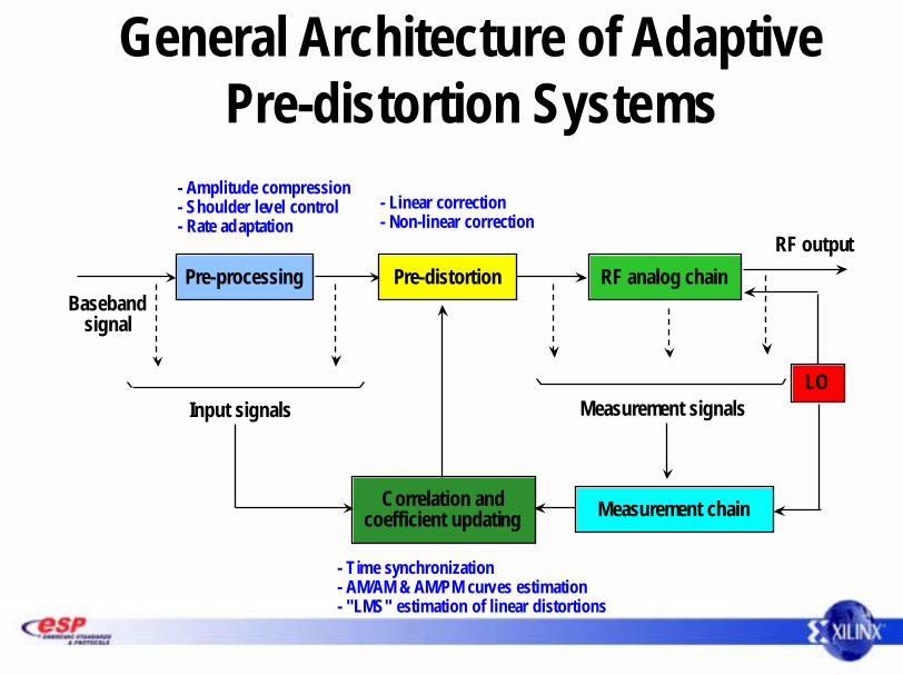
General Architecture of Adaptive Pre-distortion Systems
Baseband signal
Input signals Measurement signals
RF outputPre-processing Pre-distortion RF analog chain
Correlation andcoefficient updating Measurement chain
LO
- Amplitude compression- Shoulder level control- Rate adaptation
- Linear correction- Non-linear correction
- Time synchronization- AM/AM & AM/PM curves estimation- "LMS" estimation of linear distortions

Amplitude Compression Issues
• Loss of power efficiency if the amplifier must "pass" all the signal dynamic range– CDMA ~12 dB
• Control of the signal dynamic range at the amplifier input
• The signal may be clipped without noticeable degradation at the receiver side
– Clipping must not occur within the HPA or the pre-correction filters
• Limits the shoulder level on output
Amplitude Compression Guidelines
• Amplitude compression must be implemented at the transmitter input – Signal clipping + low-pass filter for shoulder removal– Should operate at a higher rate than the signal useful
bandwidth • Limitation of in-band degradation (Shoulder Aliasing)• Interpolation filter on input
• Need to compromise – Working frequency versus filter complexity

xQ
Amplitude Compression Implementation - Example 1
InterpolationFilter
InterpolationFilter
ShoulderFilter
ShoulderFilter
CordicAlgorithm
CordicAlgorithm
ComparatorComparatorCordic
AlgorithmCordic
Algorithm
xIρρρρ
θθθθ
Useful bandwidth Bu
Sampling frequency 2Bu to 4Bu
Target peak level
yQ
yI
http://www.xilinx.com/ipcenter/catalog/search/logicore/xilinx_cordic.htm

Amplitude Compression Implementation - Example 1
• Rectangular to polar conversion with the Cordic algorithm (16 bits)– Full Parallel : < 700 slices – Serial (16 CLK cycles per output) : < 300 slices
• Polar to rectangular conversion with the Cordic algorithm (16 bits)– Full Parallel : < 750 slices – Serial (16 CLK cycles per output) : < 350 slices
• Shoulder filter – Number of taps defined by the spectrum mask
• Usually at least 40 to 60 taps– May have complex shape (multiple channel processing)
• Complex taps– Distributed arithmetic structure well adapted for sampling rates between 20-40 MHz

InterpolationFilter
InterpolationFilter
ShoulderFilter
ShoulderFilter
Peak PowerPeak
Power
++DelayDelay
xI
xQ
Useful bandwidth Bu
Sampling frequency 2Bu to 4Bu
Target peak level
yI
yQ
Clipping Factor
Clipping Factor
I/Q Clipping signal
Soft clipping gain : - 0 if no clipping - 1 if full clipping
Amplitude Compression –Example 2

Amplitude Compression –Example 2
• Very efficient– Uses Virtex-II and Virtex-II Pro embedded multipliers
• Computation of the clipping gain may be done with a RAM block
• Gain multiplication & shoulder filter may be integrated in the direct signal path – As per Example 1
• Shoulder filter requirements– Same as Example 1

Input filterGi(f)
Input filterGi(f)
Look-Up TableLook-Up Table Output filterGo(f)
Output filterGo(f)
Pre-correction of Linear Distortions
• The input filter Gi(f) corrects the HPF linear distort ions – Inverse transform the HPF response within the signal bandwidth– May operate at symbol rate– Complex FIR filter, with adaptive coefficients
• Filter length usually 16 to 32 taps• MAC implementation usually chosen
• Output filter Go(f) – Must operate at a higher rate – Should invert the RF modulation equivalent filter over the total correction
bandwidth– Not all implementations require this filter
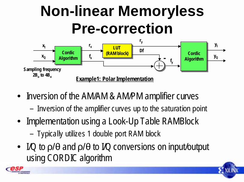
Non-linear Memoryless Pre-correction
• Inversion of the AM/AM & AM/PM amplifier curves– Inversion of the amplifier curves up to the saturation point
• Implementation using a Look-Up Table RAMBlock– Typically utilizes 1 double port RAM block
• I/Q to ρ/θ and ρ/θ to I/Q conversions on input/output using CORDIC algorithm
CordicAlgorithm
CordicAlgorithm
LUT(RAM block)
LUT(RAM block)Cordic
AlgorithmCordic
Algorithm
xI
xQ
rx
fx
Sampling frequency 2Bu to 4Bu
yI
yQ-
ry
Df
fy
Example1: Polar Implementation
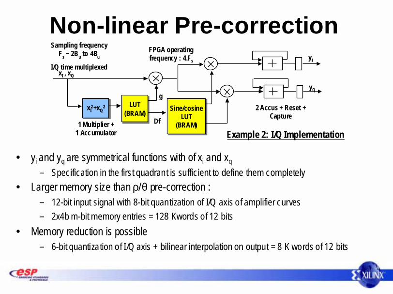
Non-linear Pre-correction
• yi and yq are symmetrical functions with of xi and xq – Specification in the first quadrant is sufficient to define them completely
• Larger memory size than ρ/θ pre-correction : – 12-bit input signal with 8-bit quantization of I/Q axis of amplifier curves – 2x4b m-bit memory entries = 128 Kwords of 12 bits
• Memory reduction is possible– 6-bit quantization of I/Q axis + bilinear interpolation on output = 8 K words of 12 bits
LUT(BRAM)
LUT(BRAM)xI
2+xQ2xI
2+xQ2
xI , xQ
Sampling frequencyFs ~ 2Bu to 4Bu
I/Q time multiplexedyI
yQg
DfSine/cosine
LUT(BRAM)
Sine/cosineLUT
(BRAM)
2 Accus + Reset +Capture
1 Multiplier +1 Accumulator
FPGA operatingfrequency : 4.Fs
Example 2: I/Q Implementation

Estimation of Correction Coefficients
• Model the amplifier characteristic– The overall dynamic scale needs to be calculated– Normally 32K to 64K samples required at modulation rate to
calculate coefficients• Feedback structure of the return path
– RF to baseband demodulation via real time (FPGA)• Analog quadrature demodulation must be avoided
– Digital demodulation needed• DDS + complex multiplication + filter
• Calculate new coefficients in software (as low rate)– Microblaze or Embedded PowerPC in Virtex-II Pro

Other Schemes
• Frequency dependent schemes– Time dependencies are added to the Look-Up Table
RAM– RAM size can grow substantially
• Joint linear and non-linear correction– Volterra– Neural network based

Xilinx Value Propositionin Pre-Distortion Applications
• Xilinx FPGAs provide the ideal feature set required for pre-distortion functions– XtremeDSP capability
• Extremely high-speed embedded multipliers• Block memory for coefficient storage
– Flexibility and Reconfigurability• Adapt designs during development and after deployment
– Soft and embedded processors• New coefficient calculation and control of the pre-distortion filter
carried out using an on-chip processor solution

Xilinx Pre-Distortion System Solution
Xilinx Memory CPU
Non-Xilinx Mixed Signal Embedded
Antenna
Buffer Me mory
DACRF
TransmitterPower Amp
TxBandpass
Filter
RF Receiver
ADCMicroBlazeor PowerPC
Dual Port Me moryFilter Coefficients &
Non-Linear Transform Table
DACI
Q
From Channel
Combiner
SystemControl
Bus
IFto
BasebandDigitalDown
Converter
Platform FPGA
Pre-Distortion Function
Linear Filter
Non-LinearCorrection
Amplitude Compression

Xilinx Software and IP Solutions
• Xilinx has a comprehensive range of IP and software to ensure speedy pre-distortion algorithm and filter development– System Generator
• Allows algorithmic development and targeting to silicon in a high-level DSP development toolset
– Mathworks & Simulink
– Coregen• Used to generate the desired filter in a simple and easy-to-use GUI based tool
– IP• Many blocks of IP available from Xilinx and our AllianceCore partners
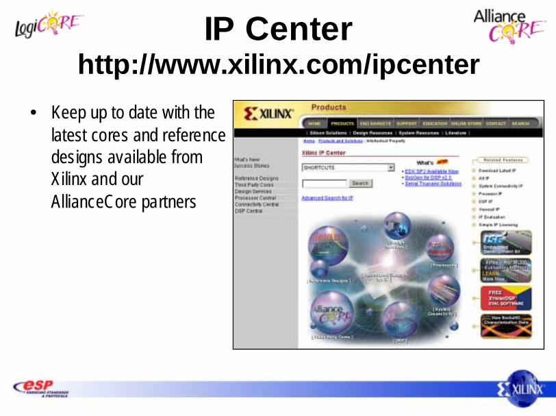
IP Centerhttp://www.xilinx.com/ipcenter
• Keep up to date with the latest cores and reference designs available from Xilinx and our AllianceCore partners

Xilinx CORE Generator
List of available IP from or
FullyParameterizable
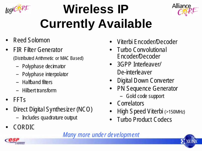
Wireless IP Currently Available
• Reed Solomon• FIR Filter Generator
(Distributed Arithmetic or MAC Based)– Polyphase decimator– Polyphase interpolator– Halfband filters– Hilbert transform
• FFTs• Direct Digital Synthesizer (NCO)
– Includes quadrature output
• CORDIC
• Viterbi Encoder/Decoder• Turbo Convolutional
Encoder/Decoder • 3GPP Interleaver/
De-interleaver• Digital Down Converter• PN Sequence Generator
– Gold code support• Correlators• High Speed Viterbi (>150MHz)• Turbo Product Codecs
Many more under development

CORDIC
Control SignalsFeatures
• Vector Rotation (Polar to Rectangular)• Vector T ranslation (Rectangular to Polar)• Trigonometric, Hyperbolic and Square Rootequations• Serial or Parallel implementation
Device Family ---------Size ----------------------Performance -----------
Design SourceBehavioral ModelInstantiation CodeTest BenchCore Source
Deliverables Applications• Math Functions used in Beam Forming, Smart Antennas etc.Smart-IP Technology Netlist
VHDL and VerilogVHDL and VerilogNoCORE Generator, IP Center
Spartan-II,Virtex/-E/-II/PRO200 slices, 16b Square root164 MHz, xc2v50-5
OutputOutputStage
Customization• Input and Output width• Compensation scaling• Rounding• Phase Format
A n-bits
Clock
Shift Add-Sub Stages
InputStage
CORDIC Engine

System Generator for DSP• Visual data flow paradigm• Polymorphic block libraries• Bit and cycle true modeling
• Seamlessly integrated with Simulink and MATLAB
– Test bench and data analysis
• Automatic code generation– Synthesizable VHDL– IP cores– HDL test bench– Project and constraint files

Summary• The use of pre-distortion offers equipment
manufacturers a way of rapidly reducing the overall cost of their systems– Cut costs in the complex analog domain– Use relatively cheap digital technology to compensate
for poor analog performance• Xilinx FPGAs have all the features needed to
implement complex pre-distortion functions