Embed Size (px)
Citation preview

Address: ngmn e. V. Großer Hasenpfad 30 • 60598 Frankfurt • Germany Phone +49 69/9 07 49 98-0 • Fax +49 69/9 07 49 98-41
PRE-COMMERCIAL NETWORKS TRIALS
MAJOR CONCLUSIONS by NGMN Alliance
Version: 2.0
Date: 17-February-2021
Document Type: Final Deliverable (approved)
Confidentiality Class: P - Public
Project: 5G Trial and Testing Initiative
Project Lead Cemil Karakus (Turkcell)
Contributors: Philippe Besson (Orange), Aitor Garcia (Vodafone), Tomas Jiricek (T-Mobile), Rexy Geevarghese (Bell), Shibo Li (China Mobile), Karri Kuoppamaki (T-Mobile USA), Giovanni Romano (TIM), Che-Wei Yeh (Chunghwa Telecom)
Approved by / Date: NGMN Board, 6th April 2021
© 2021 Next Generation Mobile Networks e.V. All rights reserved. No part of this document may be reproduced or transmitted in any form or by any means without prior written permission from NGMN e.V.
The information contained in this document represents the current view held by NGMN e.V. on the issues discussed as of the date of publication. This document is provided “as is” with no warranties whatsoever including any warranty of merchantability, non-infringement, or fitness for any particular purpose. All liability (including liability for infringement of any property rights) relating to the use of information in this document is disclaimed. No license, express or implied, to any intellectual property rights are granted herein. This document is distributed for informational purposes only and is subject to change without notice. Readers should not design products based on this document.

Pre-Commercial Networks Trials Major Conclusions, Version 2.0, February-2021
Page 2 (39)
List of Operators that shared their initial 5G trial results with NSA and SA architecture

Pre-Commercial Networks Trials Major Conclusions, Version 2.0, February-2021
Page 3 (39)
CONTENT 1 Introduction ......................................................................................................................................................................................... 4
2 Scope ..................................................................................................................................................................................................... 4
3 Executive Summary ......................................................................................................................................................................... 4
4 Trial Results ........................................................................................................................................................................................ 5
4.1 Mobility ........................................................................................................................................................................................... 6
4.1.1 NSA Mobility ..................................................................................................................................................................... 6
4.1.2 SA Mobility......................................................................................................................................................................... 7
4.1.3 5G/4G Inter-RAT Mobility ............................................................................................................................................ 8
4.2 Cell Capacity ................................................................................................................................................................................ 9
4.2.1 Cell Peak DL Throughput ............................................................................................................................................ 9
4.2.2 Cell Peak UL Throughput .......................................................................................................................................... 10
4.2.3 Cell Average Throughput ......................................................................................................................................... 11
4.3 Latency ....................................................................................................................................................................................... 12
4.3.1 Control Plane Latency ................................................................................................................................................ 12
4.3.2 User Plane E2E Latency (in connected mode) ................................................................................................. 13
4.3.3 User Plane RAN Latency (in connected mode) ............................................................................................... 14
4.4 Voice Services .......................................................................................................................................................................... 15
4.4.1 Voice Services (VoNR & EPS FallBack) ............................................................................................................... 15
4.4.2 E2E Voice Testing Results ........................................................................................................................................ 16
4.5 User Throughput and Spectral Efficiency ..................................................................................................................... 17
4.5.1 User Downlink / Uplink Throughput ..................................................................................................................... 17
4.5.2 Spectral Efficiency ....................................................................................................................................................... 19
4.5.3 Dynamic Spectrum Sharing on FDD NR ............................................................................................................ 20
4.5.4 CSI-RS Port Effect on DL Throughput Performance ..................................................................................... 22
4.5.5 Speed Impact ................................................................................................................................................................ 23
4.5.6 Carrier Aggregation combınatıon on en-dc ...................................................................................................... 24
4.6 Coverage .................................................................................................................................................................................... 25
4.6.1 5G Downlink Max Coupling Loss .......................................................................................................................... 25
4.6.2 5G Uplink Max Coupling Loss ................................................................................................................................. 26
4.6.3 5G Uplink vs. Downlink Coupling Loss Gap ...................................................................................................... 27
4.6.4 5G Uplink 2 Transmitters .......................................................................................................................................... 28
4.6.5 Outdoor Coverage ....................................................................................................................................................... 29
4.6.6 Indoor Coverage ........................................................................................................................................................... 30
4.6.7 5G Coverage Comparison Among Patterns ..................................................................................................... 31
4.6.8 5G BeamForming & Ressource Allocation ........................................................................................................ 33
5 Appendix ........................................................................................................................................................................................... 34
5.1 5G Downlink Coverage Performance - Summary .................................................................................................... 34
5.2 5G Uplink Coverage Performance – Summary .......................................................................................................... 35
5.3 5G vs. 4G Coverage - SummarY ...................................................................................................................................... 35
5.4 5G DL Throughput vs. Pathloss ........................................................................................................................................ 36
5.5 5G UL Throughput vs. Pathloss ........................................................................................................................................ 37
6 Abbreviations .................................................................................................................................................................................. 38

Pre-Commercial Networks Trials Major Conclusions, Version 2.0, February-2021
Page 4 (39)
1 INTRODUCTION
The NGMN 5G Trial & Testing Initiative (TTI) Project consists of four phases summarized as follows:
• Tests of technology building blocks: (e. g. Massive MIMO, new waveforms…) The member companies may be individually evaluating candidate technologies during the pre-5G deployment period.
• Proof of concept (PoC): The basic features of the radio interface, core network and 5G architectural components as specified by the Third Generation Partnership Project (3GPP). The PoC may be performed using solutions which may be partially proprietary.
• Interoperability phase includes testing of the network aspects and device/network interoperability.
• Pre-commercial networks trials phase with equipment close to commercial quality standard. This phase focuses on an initial planning phase (including test specifications), followed by the trials (with pre-commercial equipment installed on sites).
This document focuses on the Pre-commercial network trials phase actual trial results.
2 SCOPE
Pre-commercial networks trials project has two phases:
• Planning & Test specifications: Developing a testing framework for 5G NR based on 3GPP standards allowing the harmonization of the testing methodologies between the different partners. It includes definition of trials setup, requirements, and test cases.
• Version 3 of the framework document is already released and available from the following web link. Definition of the Testing Framework for the NGMN 5G Pre-Commercial Networks Trials
• Performing trials: Installation and setup of trial network and testing and performance reporting of the results.
This document focuses on performing trials phase. The main purpose is to assess and benchmark the performance of the 3GPP compliant 5G NR (release 15) in live field conditions with pre-commercial equipment.
3 EXECUTIVE SUMMARY
Given the freeze of 3GPP Release 15 5G standards and the onset of some initial 5G commercial deployments in countries such as South Korea, many operators accelerated their 5G trials in 2019. As a part of NGMN 5G Trial and Testing Initiative (TTI) project, NGMN operators, whose names are given above, shared their initial 5G trial results.

Pre-Commercial Networks Trials Major Conclusions, Version 2.0, February-2021
Page 5 (39)
Pre-commercial network trials phase of 5G TTI aims to consolidate the results from different operators and reach some major conclusions. In order to achieve this, trials shall be done based on testing framework document which was designed for this purpose. In the framework document, available from above link in scope section, all test requirements, procedures, and success criteria (if possible) are clearly stated. Due to the infancy of solutions from some vendors, equipment limitations and site constraints, not all tests were executed as per the framework document. Where possible, some of the results are consolidated with a fair approach and for some independent tests, the results are shared by referring operator’s name. For each section, the owners of the trials are stated as rapporteurs. The results are evaluated by either explicitly stating they are passed according to NGMN criteria or stating the observation of trial. Although there are more test sections for NSA and SA configuration in the framework document, eight of them attracted more attention by operators and related results are shared within this document. These are the most important aspects of mobile communication to show its characteristics, therefore we hope it will take great attention by the ecosystem. With the second version, more SA results as well as Dynamic Spectrum Sharing on FDD NR and other special trial results (e.g. speed impact) have been added to the document. Due to the Covid-19 effect, latter trials could be performed with some delay from the planned date. Anyway, NGMN partners did their best to complete the trials and bring interesting results. Overall, this consolidation effort, which gathers Trial reports mostly performed using a common methodology, draws some very promising conclusions on the performances of early 5G implementations. Additionally, it brings some observations that could lead to future improvements.
4 TRIAL RESULTS
9 operators shared their initial 5G trial results with NSA and SA networks for main scenarios below:
• Mobility
• Inter-RAT procedures
• Cell capacity
• Latency
• Voice services
• User throughput
• Spectral efficiency
• Coverage

Pre-Commercial Networks Trials Major Conclusions, Version 2.0, February-2021
Page 6 (39)
4.1 MOBILITY This section focuses on intra-cell mobility and inter-cell mobility (handover) scenarios. Only packet switched data scenarios are considered. Standalone (SA) and Non- Standalone (NSA) configurations are both covered in this section.
4.1.1 NSA MOBILITY
Rapporteurs:
Functional tests: All inter-cell mobility tests passed!
• Scenario 1: same MeNB, same SgNB, different SCG
• Scenario 2: same MeNB, different SgNB
• Scenario 3: different MeNB, same SgNB
• Scenario 4: different MeNB, No SgNB
*Handover interruption time: Time during which the user is not able to receive any user plane data.
Key Observations:
• Some vendors still don’t support NR cell mobility in NSA, NR cell is deleted and re-added during NR and/or Master LTE cell change.
• Small amount of user plane interruption time (less than 20ms) is observed even for NR-NR change. DL PDCP aggregation between LTE & NR leverages almost continuous data transfer.
• Control plane interruption time for intra/inter eNodeB Master LTE handover is between 20ms and 60ms which is similar to LTE.

Pre-Commercial Networks Trials Major Conclusions, Version 2.0, February-2021
Page 7 (39)
4.1.2 SA MOBILITY
Rapporteurs:
Key Observations:
• Intra and inter gNodeB handover tests are successfully completed in SA mode.
• Control plane handover interruption time is between 15 ms and 45 ms.
• User plane handover interruption time is between 17 ms and 62 ms.
• The results vary from vendor to vendor and the gap is huge. The Standalone architecture ecosystem is not still mature at time of trials performed by different operators.
• The minimum values observed during trials (e.g. 17-20ms) seem acceptable for eMBB case but for URLLC, improvements need to be done. (e.g. UE supports simultaneous Tx/Rx with the source cell and the target cell).

Pre-Commercial Networks Trials Major Conclusions, Version 2.0, February-2021
Page 8 (39)
4.1.3 5G/4G INTER-RAT MOBILITY
Rapporteurs:
Key Observations:
• Both 5G -> 4G Handover and 4G <- 5G Handover tests are completed successfully.
• Interruption times are similar to LTE handovers
• Without N26 interface which is between 5GC and EPC, interruption time is very high compared to a case with N26 interface.
Pre-Commercial Networks Trials Major Conclusions, Version 2.0, February-2021
Page 9 (39)
4.2 CELL CAPACITY
4.2.1 CELL PEAK DL THROUGHPUT
Rapporteurs:
Key Observations:
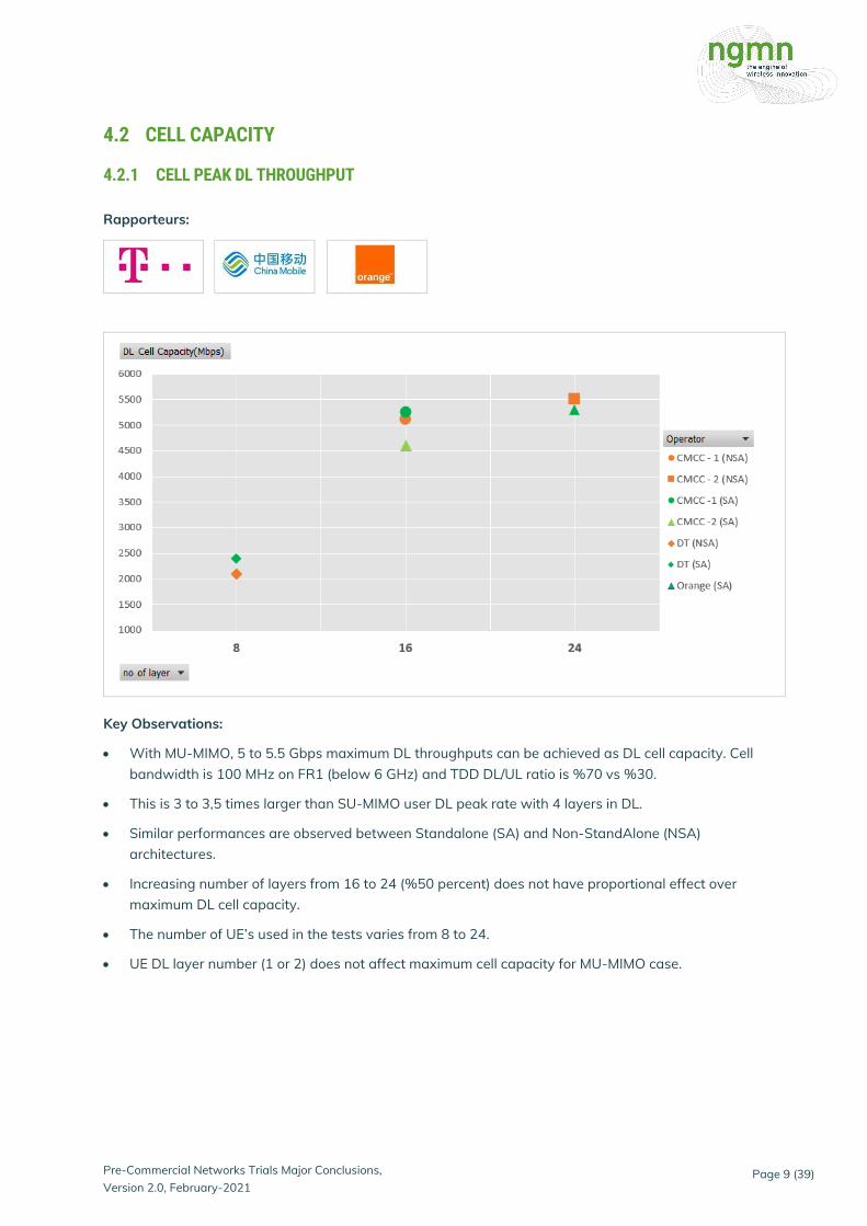
• With MU-MIMO, 5 to 5.5 Gbps maximum DL throughputs can be achieved as DL cell capacity. Cell bandwidth is 100 MHz on FR1 (below 6 GHz) and TDD DL/UL ratio is %70 vs %30.
• This is 3 to 3,5 times larger than SU-MIMO user DL peak rate with 4 layers in DL.
• Similar performances are observed between Standalone (SA) and Non-StandAlone (NSA) architectures.
• Increasing number of layers from 16 to 24 (%50 percent) does not have proportional effect over maximum DL cell capacity.
• The number of UE’s used in the tests varies from 8 to 24.
• UE DL layer number (1 or 2) does not affect maximum cell capacity for MU-MIMO case.

Pre-Commercial Networks Trials Major Conclusions, Version 2.0, February-2021
Page 10 (39)
4.2.2 CELL PEAK UL THROUGHPUT
Rapporteurs:
Key Observations:
• With MU-MIMO, 600 to 800 Mbps maximum UL throughputs can be achieved as UL cell capacity.
• This is 3 to 4 times larger than SU-MIMO user UL peak rate with 2 layers in UL.
• Similar performances are observed between Standalone (SA) and Non-StandAlone (NSA) architectures.
• Increasing number of layers from 4 -> 8 -> 12 has major affect over maximum UL cell capacity.
• The number of UE’s used in the tests varies from 4 to 8.

Pre-Commercial Networks Trials Major Conclusions, Version 2.0, February-2021
Page 11 (39)
4.2.3 CELL AVERAGE THROUGHPUT
Rapporteurs:
Key Observations:
• From uniform to non-uniform distribution, average DL cell throughput is reduced by 25% to 60% since multi-user pairing performance is degraded because of worse space isolation between users.
• For mobility scenarios, multi-user pairing performance is degraded, the rate is about 500~800Mbps, which is 45% ~ 75% lower than the static uniform scenario. Multi-user pairing and scheduling algorithms under different conditions still need to be optimized.
• There is a huge gap between different vendors and chipsets, whole ecosystem is still not mature at the time of trials.
• No major performance differentiation in SA architecture. Consistent gain about 250% of MU-MIMO over SU-MIMO is observed.

Pre-Commercial Networks Trials Major Conclusions, Version 2.0, February-2021
Page 12 (39)
4.3 LATENCY Latency is a very important parameter for enabling 5G use cases, particularly the URLLC use case for Latency-critical applications, such as, factory or home automation, automated vehicles, gaming services, remote computing... This section brings early 5G Latency performance reports with pre-commercial 5G solutions (infrastructure, transport and devices) through most significant testing configuration cases. Both control plane and user plane latencies are considered.
4.3.1 CONTROL PLANE LATENCY
Rapporteurs:
These tests are intended to validate different mobility state transitions (control plane) and their transitions times. More specifically, tests aim to:
• Quantify “Idle to Connected”/ “Connected to Idle”, and “Inactive
• to Connected”/ “Connected to Inactive” state transition times.
• Verify the associated process for each type of state transition.
Expected target value in standalone (SA) configuration: NGMN recommendations = Idle <->
Connected transition time ≤ 10 ms
NGMN recommendations = Inactive <->
Connected transition time ≤ 10 ms.

Pre-Commercial Networks Trials Major Conclusions, Version 2.0, February-2021
Page 13 (39)
Initial conclusions:
• NGMN objectives in SA are not yet met. In SA architecture, about 23ms and 45ms control plane latency is observed for Inactive to connected and Idle to Connected respectively.
• The implementation of a specific Low Latency Communication slice has no influence on call setup times.
4.3.2 USER PLANE E2E LATENCY (IN CONNECTED MODE)
Rapporteurs:
For the sake of clarity, Round Trip Times (RTT) for both RAN and End to End Latencies were considered.
Success criteria for eMBB:
• RAN latency ≤ 8 ms
• E2E latency with 200 km distance between NR node and EPC/NGCore + Application server ≤ 10-15 ms

Pre-Commercial Networks Trials Major Conclusions, Version 2.0, February-2021
Page 14 (39)
Initial conclusions:
• The End to End Latency slightly increases with the packet size.
• The radio link quality has a low impact of on the End to End Latency for low packet sizes.
• Early results in SA architecture are very promising.
• Core – RAN distance plays a key role in the e2e latency results, which reveals the need for MEC.
4.3.3 USER PLANE RAN LATENCY (IN CONNECTED MODE)
Rapporteurs:

Pre-Commercial Networks Trials Major Conclusions, Version 2.0, February-2021
Page 15 (39)
Initial Conclusions:
• The radio link quality has a low impact of on the End to End Latency for small packet sizes.
• The optimization of the network and the implementation of specific features (e.g. pre- allocation, slicing) have a significant impact on the Latency results, regardless of the architecture.
• TDD framing format will also influence latency timing. As the switch period from DL to UL is reduced, NR latency can see improved results.
• Early results in SA architecture are very promising.
• Latency results were obtained with one single user. However, when the network is not congested, the number of users (up to 10 in a cell) has no impact on the Latency.
4.4 VOICE SERVICES
4.4.1 VOICE SERVICES (VONR & EPS FALLBACK)
Rapporteurs:
2 ways to support voice services in 5G SA were tested.
And 2 key aspects of voice in 5G SA were tested with or without N26 interface (between AMF & MME):
• The impact of 5G-4G mobility procedure on Voice Service During a VoNR call, when 5G coverage is no more available, the call has to be seamlessly moved to 4G.
• The impact of EPS Fallback (EPS-FB) on Call Set up Time (CST) EPS-FB triggers inter-system Hand Over during call establishment which impacts the CST
VoNR: Voice over New Radio & 5GC – EPS: Evolved Packet System; 4G – AMF: Access and Mobility Management Function, 5G

Pre-Commercial Networks Trials Major Conclusions, Version 2.0, February-2021
Page 16 (39)
4.4.2 E2E VOICE TESTING RESULTS
Rapporteurs:
Test case Type of Voice call Observations
Mobility 5G (VoNR) to 4G (VoLTE) mobility
With N26 interface voice interruption time is 70ms Without N26 interface, the interruption time is 700ms (recommended limit for a voice call = 300ms)
Call set up time
Originating 5G (EPS-FB) to 4G (VoLTE) Originating 5G (VoNR) to 4G (VoLTE)
With EPS-FB, the Call Setup Time is 1s more than with VoNR (with N26) and still slightly increased without N26 (+ 0,5s).
Initial Conclusions:
• VoNR & EPS Fallback calls successfully passed in 5G Standalone Architecture mode
• Standardization requirements seem correctly implemented
• Performance and voice quality seem good in initial trials
• VoNR Call Setup Time is expected to be at least as good as for VoLTE (2 - 3,5 sec).
• Increase of Call Setup Time for voice with EPS-FB is expected to stay limited: ~1 sec. more than VoNR (with N26) which should have a limited impact on the end user experience
• N26 is needed for best seamless voice continuity in mobility. Without N26, 10 times larger mobility interruption time is observed (70ms vs 700ms)
• EPS-FB needs to fallback from 5G to 4G network, therefore the coverage of 4G and 5G will affect EPS-FB voice service performance

Pre-Commercial Networks Trials Major Conclusions, Version 2.0, February-2021
Page 17 (39)
• Ecosystem is not mature (terminal, network, optimization…) for VoNR so average MOS of VoNR perceived by users is slightly less than MOS of VoLTE at time of trials
4.5 USER THROUGHPUT AND SPECTRAL EFFICIENCY
4.5.1 USER DOWNLINK / UPLINK THROUGHPUT
Rapporteurs:
Success criteria ([eMBB use case]; < 6GHz, 100 MHz BW; dense-urban environment)
• For 4x4 DL MIMO, 5G should deliver around 1.75 Gbps DL peak rate with DDDSU slot configuration.
• For UL assuming 2x2 UL MIMO, 5G should deliver around 200 Mbps UL peak rate with DDDSU slot configuration and 64QAM modulation.
• NGMN: 100X improvement over LTE (3GPP Release-12) for UL/DL data rate on cell edge (assuming centralized architecture) (NGMN White Paper 6: 50 Mbps and 25 Mbps).

Pre-Commercial Networks Trials Major Conclusions, Version 2.0, February-2021
Page 18 (39)
Initial Conclusions:
• There are differences between the results due to the different conditions of individual trials, which were also done in different stages of the NR implementation development.
• SA and NSA trial DL throughput results are similar for peak values as expected. However, the average and edge DL throughput results are superior in SA than NSA. This is mainly due to fact

Pre-Commercial Networks Trials Major Conclusions, Version 2.0, February-2021
Page 19 (39)
that the SA trials are performed at least one year later than NSA trials and terminal, network and optimization features are becoming more mature day by day.
• SA UL throughput performance is improved at least by double thanks to the uplink MIMO in UEs.
• TDD frame structure plays a key role for UL/DL throughput results.
• For peak measurement we can see that the results are close to the target but still need some improvements.
• The target values for average and edge user throughput were mostly reached during the trials however tests should be repeated under loaded 5G networks.
4.5.2 SPECTRAL EFFICIENCY
Rapporteurs:
Success criteria (eMBB use case)
• 3GPP peak spectral efficiency targets (eMBB use case): 30 Bit/s/Hz for DL(8X8MIMO), 15 Bit/s/Hz for UL
• ITU-R medium spectral efficiency targets (eMBB use case): 7.8 Bit/s/Hz for DL, 5.4 Bit/s/Hz for UL
• ITU-R cell edge spectral efficiency targets (eMBB use case): 0.225 Bit/s/Hz for DL, 0.15 Bit/s/Hz for UL

Pre-Commercial Networks Trials Major Conclusions, Version 2.0, February-2021
Page 20 (39)
*Results are recalculated based on TDD frame structure
Initial Conclusions:
• There are differences between the results due to the different conditions of individual trials, which were also done in different stages of the NR implementation development.
• Downlink peak spectral efficiency targets are close however because of commonly deployed single uplink transmitter for NR in NSA devices, UL spectral efficiency targets are far away to be met in live 5G NSA networks.
• Uplink peak spectral efficiency is approximately 2.4 times better in SA trials thanks to the uplink MIMO and 256 QAM.
• The values for average and edge throughput were mostly reached during the trials.
4.5.3 DYNAMIC SPECTRUM SHARING ON FDD NR
Rapporteurs:

Pre-Commercial Networks Trials Major Conclusions, Version 2.0, February-2021
Page 21 (39)
Initial Conclusions about Downlink Performance:
• 4 to 10 percent LTE DL throughput degradation because of NR control channels overhead compared to current LTE cell downlink capacity
• 15 to 30 percent NR DL throughput degradation because of LTE control channels (especially CRS) overhead compared to FDD frequency downlink capacity which is refarmed to NR
• Additional DL performance degradation on NR due to interference from LTE neighbor cells on DSS band is expected (the percentage of degradation is under study)
• This is mainly due to non-support of interference cancellation of 4G signalization by 5G UEs (contrary to 4G UEs)
Initial Conclusions about Uplink Performance:
• 3 to 13 percent LTE UL throughput degradation because of NR overhead compared to current LTE cell uplink capacity
• 5 to 18 percent NR UL throughput degradation because of LTE overhead compared to FDD frequency uplink capacity which is refarmed to NR

Pre-Commercial Networks Trials Major Conclusions, Version 2.0, February-2021
Page 22 (39)
4.5.4 CSI-RS PORT EFFECT ON DL THROUGHPUT PERFORMANCE
Rapporteurs:
Key Observations:
• 16 and 32 Ports CSI-RS compared to 8 ports increase the DL throughput performance significantly at cell middle.
• No gain is observed at cell center.
• The gain is only visible with 32 ports at cell edge.

Pre-Commercial Networks Trials Major Conclusions, Version 2.0, February-2021
Page 23 (39)
4.5.5 SPEED IMPACT
Rapporteurs:
Trial Setup:
• Speed tests are carried out on the oval race track.
• Tracks are recorded all over the circuit at different speeds ranging from 10km/h to 200 km/h for 10 minutes each

Pre-Commercial Networks Trials Major Conclusions, Version 2.0, February-2021
Page 24 (39)
• Full buffer UDP traffic is sent during the test
• NR at 3,5GHz with 100 MHz bandwidth & LTE Anchor at 700 MHz with 10 MHz bandwidth Key Observations:
• Degradation of throughput due to speed is not as important as expected
• Cell center performances are still constant even at high speeds due to the circuit topology
• Good performances are observed from center to the edge of the cell
• At 200 km/h speed, cell edge performance is around 193 Mbps
• Performances are sensitive to speed but the impact is device dependent
4.5.6 CARRIER AGGREGATION COMBINATION ON EN-DC
Rapporteurs:
Key Observations:
• Achievable peak throughput depends on CA combinations supported by UE in EN-DC.
• Especially for NR in low-bands case, in order to make total observed throughput by UE competitive with /superior to current LTE Advanced scenario, many CA combination in EN-DC should be supported by ecosystem.

Pre-Commercial Networks Trials Major Conclusions, Version 2.0, February-2021
Page 25 (39)
4.6 COVERAGE
4.6.1 5G DOWNLINK MAX COUPLING LOSS
Rapporteurs:
(*) Results for tests with 80W cell power for 60MHz bandwidth. The difference in downlink results could be related to uplink max transmitted power reached earlier with TCP vs UDP. The TCP to UDP gap is incremental as the cell power is increased from 80W to 120W and 200W
Key Observations:
• 5G Downlink maximum coupling loss ranges from 140.8 to 148.8 dB
• DL 10Mbps is observed at 4-11 dB less
• No major difference between SA and NSA
Pre-Commercial Networks Trials Major Conclusions, Version 2.0, February-2021
Page 26 (39)
4.6.2 5G UPLINK MAX COUPLING LOSS
Rapporteurs:
Key Observations:
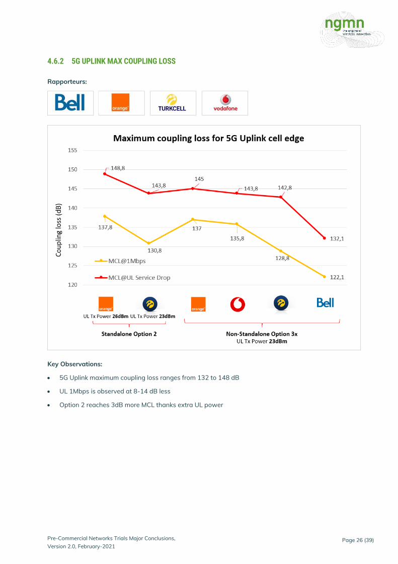
• 5G Uplink maximum coupling loss ranges from 132 to 148 dB
• UL 1Mbps is observed at 8-14 dB less
• Option 2 reaches 3dB more MCL thanks extra UL power
Pre-Commercial Networks Trials Major Conclusions, Version 2.0, February-2021
Page 27 (39)
4.6.3 5G UPLINK VS. DOWNLINK COUPLING LOSS GAP
Rapporteurs:
Key Observations:
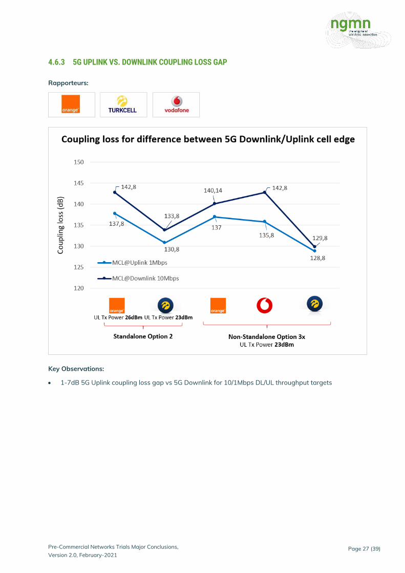
• 1-7dB 5G Uplink coupling loss gap vs 5G Downlink for 10/1Mbps DL/UL throughput targets

Pre-Commercial Networks Trials Major Conclusions, Version 2.0, February-2021
Page 28 (39)
4.6.4 5G UPLINK 2 TRANSMITTERS
Rapporteurs:
Key Observations:
• Up to 6 times UL throughput at bad radio conditions when using 2 transmitters in device with +3dB transmitted power vs 1 transmitter
• With 256QAM and 2 transmitters in the uplink, up to 2.4 times peak uplink throughput can be observed

Pre-Commercial Networks Trials Major Conclusions, Version 2.0, February-2021
Page 29 (39)
4.6.5 OUTDOOR COVERAGE
Rapporteurs:

Pre-Commercial Networks Trials Major Conclusions, Version 2.0, February-2021
Page 30 (39)
Key Observations:
• The 5G NR signal level has an average coverage gain about +1dB vs 4G2100 but gain is not positive near base station
• Because of different beamforming characteristics of CSI-RS and SSB signals, CSI-RS Signal to Interference Noise (SINR) is much better than SSB SINR.
• Different CSI-RS and SSB implementations are observed between vendors.
4.6.6 INDOOR COVERAGE
Rapporteurs:

Pre-Commercial Networks Trials Major Conclusions, Version 2.0, February-2021
Page 31 (39)
Key Observations:
• Full range of RSRPs up to -120dBm (indoor starting at -75dBm and outdoor starting at -55dBm) are observed during trial.
• Indoor downlink performance is similar or slightly better than outdoor.
• Indoor uplink performance is worse than outdoor for RSRP values less than -95 dBm.
4.6.7 5G COVERAGE COMPARISON AMONG PATTERNS
Rapporteurs:

Pre-Commercial Networks Trials Major Conclusions, Version 2.0, February-2021
Page 32 (39)
Key Observations:
• Pattern 0 maximizes the coverage area at ground level as expected since horizontal antenna width is 105°, while pattern 4 and 16 having a smaller horizontal antenna width reduce the coverage extension.
Test conditions:
• NSA Option 3x
• 3.7GHz 80MHz 30KHz SCS 8:2 DL/UL pattern
• 4x4MIMO 256QAM DL/ 2x2MIMO 64QAM UL
• gNB power 66W, UE UL Tx power TBC
• Different beam patterns measured
• Outdoor & Mobility condition (max 50 Km/h)
• Isolated cell
• Full buffer UDP

Pre-Commercial Networks Trials Major Conclusions, Version 2.0, February-2021
Page 33 (39)
4.6.8 5G BEAMFORMING & RESSOURCE ALLOCATION
Rapporteurs:
1 Initial State
2 Final State Trial Setup:
• 2 UE’s continuously downloading 400 Mbps UDP
• UE 1 is static at location B
• UE 2 is moving from point H to point G. Key Observations: Initial state:
• Each CPE is managed by the scheduler of gNB as «single user in cell independent from the other»
• full time resources (1600)
• 144 RB (assigned by gNB scheduler)
• rank 2 (two polarizations)

Pre-Commercial Networks Trials Major Conclusions, Version 2.0, February-2021
Page 34 (39)
Final state: When CPEs get closer to each other, beams cannot be separated anymore. CPEs start sharing resource in time and frequency, and gNB scheduler starts to work on RB allocation and MIMO ranks:
• half of time resources (1600 → 800)
• full RB (144 → 208)
• rank 2 → 3 → 4
5 APPENDIX
5.1 5G DOWNLINK COVERAGE PERFORMANCE - SUMMARY
• Maximum Coupling Loss (MCL) from 140.8 to 148.8 dB to drop the service based on different trial results
• 10Mbps Cell edge throughput level is reached with a range between 4-11dB less
• At 1,33W/MHz cell power, there is almost no difference between TCP and UDP at 3,33W/MHz a gap appears between TCP and UDP performance due to UL coverage limitation
• Because of different beamforming characteristics of CSI-RS and SSB signals, CSI-RS Signal to Interference Noise (SINR) is much better than SSB SINR. Different CSI-RS and SSB implementations are observed between vendors.
• 3 Different horizontal/vertical beam patterns were tested by Tim, results as expected
• Indoor coverage: full range of RSRPs up to -120dBm indoor starting at -75dBm from -55dBm outdoor reference
• No differences between SA and NSA are reported by the trials performed by Orange

Pre-Commercial Networks Trials Major Conclusions, Version 2.0, February-2021
Page 35 (39)
5.2 5G UPLINK COVERAGE PERFORMANCE – SUMMARY
• Maximum coupling loss from 130 to 145 dB to drop the service based on different trial results
• 1Mbps Cell edge throughput is reached with a range between 8-14 dB less
• Up to 7dB 5G uplink coupling loss gap vs 5G downlink for 10/1Mbps DL/UL throughput targets. Dynamic 5G UL data fallback to LTE is required to extend downlink coverage
• Option 2 reaches 3dB more MCL thanks to extra 3dB UL power
• Up to 6 times UL throughput at bad radio conditions when using 2 transmitters in device with +3dB transmitted power vs 1 transmitter
5.3 5G VS. 4G COVERAGE - SUMMARY
• Results are not conclusive but there is an agreement on describing the 5G NR 3.5-3.7GHz downlink coverage somewhere between the 1800MHz and 2100MHz bands, real value is very dependent on several factors like urban/sub-urban scenario, vendor beamforming capabilities, device maturity and TDD settings
• Especially controversial is the definition on whether the SSB-RSRP or CSI-RS should be used as reference for 4G coverage gain estimation
• Vodafone: Aprox 2dB better signal strength was observed vs 4G2100 RS when using the SSB at the Vodafone trial. As for the CSI-RS as reference, the gain is positive from coupling loss aprox. 120dB but negative below which would mean there is a positive gain at medium/cell edge but negative closer to the base station, probably related to beamforming maturity
• Turkcell: C-Band 5G NR coverage seems close to LTE 1800 coverage. CSI-RS RSRP is 4dB better than SSB RSRP
• Bell: Average 7dB stronger SINR in test cluster of 5G SSB vs 4G RS is reported by Bell

Pre-Commercial Networks Trials Major Conclusions, Version 2.0, February-2021
Page 36 (39)
5.4 5G DL THROUGHPUT VS. PATHLOSS Rapporteurs:
• Orange Option 2 (SA): drop at -131dBm, 10Mbps@-125dBm
• Orange Option 3 (NSA): drop at -131dBm, 10Mbps@-124dBm
• Vodafone Option 3 (NSA): Min RSRP -130dBm, 10Mbps@-125dBm
• Turkcell Option 2 (SA): Min RSRP -126dBm, 10Mbps@-116dBm
• Turkcell Option 3 (NSA): Min RSRP -123dBm, 10Mbps@-112dBm
• DT Option 2 (SA): drop at -130dBm, 10Mbps@-128dBm
• While LOS shows generally better throughput vs NLOS vs distance, there are some areas where this is not the case. It is dependent on the radio environment (mainly reflections)
• 5G peaks reached with SSB RSRP between -65dBm and -80dBm due to 4x4MIMO allocation, up to 150m distance
• 5G drops due to poor 4G anchor signal quality: 5G NR requires a wider 4G anchor cell layout

Pre-Commercial Networks Trials Major Conclusions, Version 2.0, February-2021
Page 37 (39)
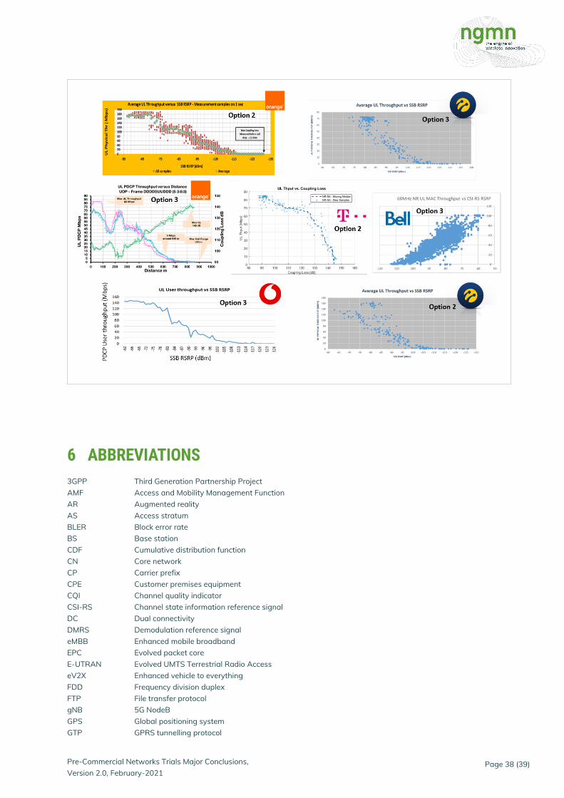
5.5 5G UL THROUGHPUT VS. PATHLOSS Rapporteurs:
• Orange Option 2: drop at -131dBm, 1Mbps@-115dBm
• Orange Option 3: drop at -124dBm, 1Mbps@-116dBm
• Vodafone Option 3: Min RSRP -126dBm, 1Mbps@-118dBm
• Bell Option 3: Min RSRP at -113dBm, 1Mbps@-110dBm
• Turkcell Option 2: Min RSRP -126dBm, 1Mbps@-113dBm
• Turkcell Option 3: Min RSRP -125dBm, 1Mbps@-111dBm
• DT Option 2: drop at -133dBm, 1Mbps@-130dBm
• UL peaks stable up to approx. -75dBms, 300m distance, thanks to good 2x2MIMO performance
• Gap between NR DL and UL is 7-10dB
Pre-Commercial Networks Trials Major Conclusions, Version 2.0, February-2021
Page 38 (39)
6 ABBREVIATIONS
3GPP Third Generation Partnership Project AMF Access and Mobility Management Function AR Augmented reality AS Access stratum BLER Block error rate BS Base station CDF Cumulative distribution function CN Core network CP Carrier prefix CPE Customer premises equipment CQI Channel quality indicator CSI-RS Channel state information reference signal DC Dual connectivity DMRS Demodulation reference signal eMBB Enhanced mobile broadband EPC Evolved packet core E-UTRAN Evolved UMTS Terrestrial Radio Access eV2X Enhanced vehicle to everything FDD Frequency division duplex FTP File transfer protocol gNB 5G NodeB GPS Global positioning system GTP GPRS tunnelling protocol

Pre-Commercial Networks Trials Major Conclusions, Version 2.0, February-2021
Page 39 (39)
GUI Graphical user interface HARQ Hybrid automatic repeat request IoT Interference over thermal IP Internet protocol KPI Key performance indicator LOS Line of sight LTE Long term evolution MCG Master cell group MCS Modulation and coding scheme MEC Multi-access edge computing MIMO Multiple input multiple output mMTC Massive machine type communication MOS Mean opinion score MTU Max transfer unit NAS Non-access stratum NGC Next generation core network NGMN Next generation mobile networks NLOS Non-line of sight NR New radio NSA Non-standalone OSI Open Systems Interconnection PBCH Physical broadcast channel PDCCH Physical downlink control channel PDCP Packet Data Convergence Protocol PDN Packet data network PDSCH Physical downlink shared channel PING Packet internet groper PLR Packet loss rate PoC Proof of concept PRB Physical resource block PSS Primary synchronization signal PUCCH Physical uplink control channel PUSCH Physical uplink shared channel QoS Quality of service RAN Radio access network RAT Radio access technology RLC Radio link control RRC Radio resource control RSRP Reference Signal Received Power RSRQ Reference Signal Received Quality RTT Round trip time SA Standalone SCG Secondary cell group SINR Signal to interference and noise ratio SNR Signal to noise ratio SRS Sounding reference signal SSS Secondary synchronization signal TCP Transmission control protocol TDD Time division duplex TTI Trial & Testing Initiative UDP User datagram protocol UE User equipment uRLLC Ultra-reliable low latency communications vBBU Virtualized baseband unit VR Virtual reality