Embed Size (px)
DESCRIPTION
Pratt and Whitney Wasp rebuild manual
Citation preview
-',r,i., -r:i,,.
OVERIIAT]LMANUAL
(Part No. tt8616)
Ucrqz /o.8, //aap,J/t
J/urLlrcJ I Serzip't 8,4qilrcrrSEGOI{D EDITIOil
PRATT & WHITilEY AIRGRAFTDipision of
TJNITED AIRCRAFT CORPORATION
EAST HARTFORD, CONNECTICUT
kinted in Unit d Strtr of Amcica
ET
PREFACE
This second edition of the Wasp Jr. B, Wasp Hl,and Hornet E
Series Overhaul Manual incorporates only minor revisions to the
January, 1941,edition and does not necessarily supersede it.
L)
42* P83ld\ \ " \ \ ' \ \ 3
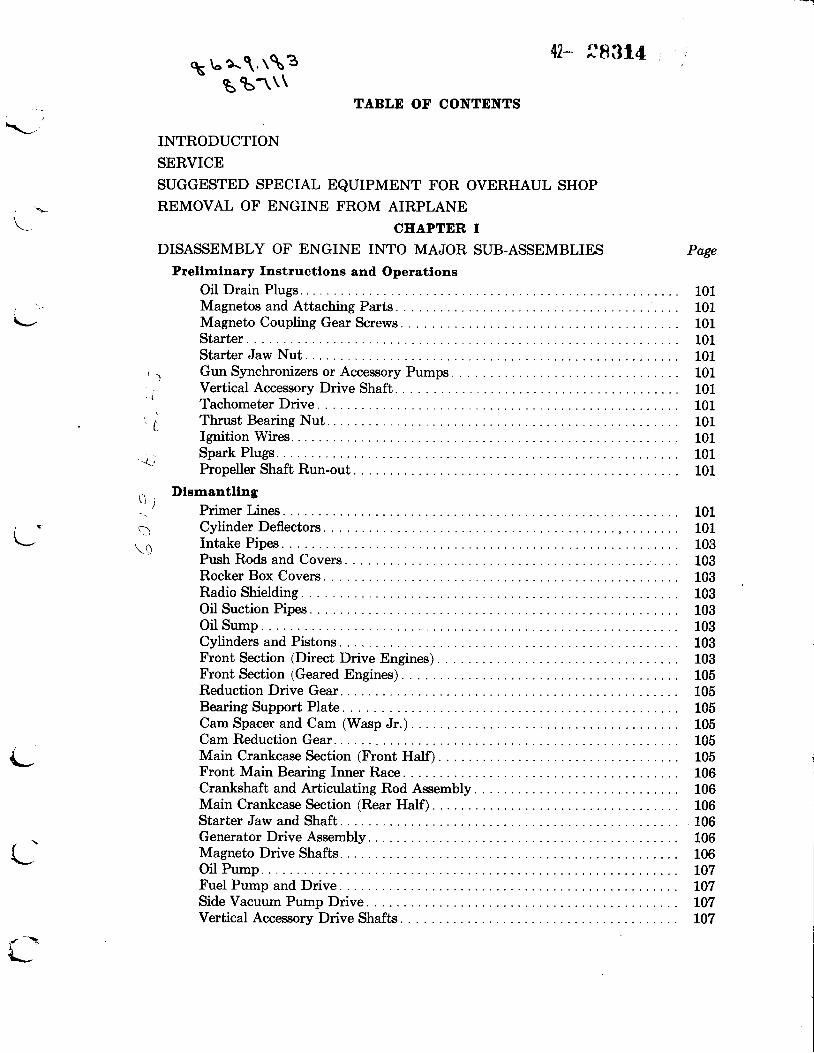
B t1\\TABLE OF CONTENTS
INTRODUCTION
SERVICE
SUGGESTED SPECIAL EQUIPMENT FOR OVERHAUL SHOPREMOVAL OF ENGINE FROM AIRPLANE
CIIAPTER IDISASSEMBLY OF ENGINE INTO MAJOR SUB-ASSEMBLIES
Prellrnlnary Instructlons and OperatlonsOil Drain PlugsMagnetos and Attaching Parts.Magneto Coupling Gear Screws.Starter.Starter Jaw NutGun Synchronizers or Accessory Pumps
Page
L.
-..t
* ( ;
Nut.
101101101101101101101
Vertical Accessory Drive Shaft.
101101101
101101
Tachometer Drive.
i Thrust BearingIgnition Wires.
' . i I
n\ q
Spark Plugs.Propeller Shaft Run-out.
DlsmantllngPrimer Lines. 101Cylinder Deflectors 101Intake Pipes. 103Push Rods and Covers 103Rocker Box Covers 103Radio Shielding 103Oil Suction Pipes. 103Oil Sump.Cylinders and PistonsFront Section (Direct Drive Engines)Front Section (Geared Engines)Reduction Drive Gear.Bearing Support Plate.Cam Spacer and Cam (Wasp Jr.). .Cam Reduction Gear.Main Crankcase Section (Front Half).Front Main Bearing Inner Race.Crankshaft and Articulating Rod AssemblyMain Crankcase Section (Rear Half).Starter Jaw and Shaft.Generator Drive AssemblyMagneto Drive Shafts.Oil PumpFuel Pump and DriveSide Vacuum Pump DriveVertical Accessory Drive Shafts
e
103103103105105105105105105106106106106106106107L07L07107
{\-
CEAPTDR I (contlnued)
DISASSEMBLY OF ENGINE INTO MAJOR SUB-ASSEMBLIES (continued) Page
Dlsmantllng (contlnued)
Oil Drain Pipe. . L07Carburetor Hotspot (If Provided). . . 108
' -....-rJ' t\._,/-'-
I
I
\-,
\
Oil Pressure Relief Valve 108Separating Rear and Blower Sections. .Magneto Drive Gear (on Magneto). . . .
108108
Tool Llst 109
CHAPTER IIDISASSEMBLY OF MAJOR SUB-A$SEMBLIES
Front (Nose) Seatlon - Wasp Jr.Tappets and Rollers (Wasp Jr. B and 82)Rocker Oil Manifold (Wasp Jr. 83)Front Breather Assembly (If Provided). . .Propeller Regulator ValveThrust Bearing
Front (Nose) Seotlon - Wasp Hl and Hornet D (Dlreat Drlve)Propeller Oil Feed Pipe Assembty.Governor DriveThrust Bearing
Front Sectlon (Reductlon Gearlng and Eouslng Assembly) trrasp Hl-G,Eornet E-G and Ez-G
Reduction Gearing.Pinion Cage.Propeller Oil Feed Pipe. .Fixed GearGovernor DrivePropeller Shaft.
(Hornet E-G and E2-G onty)
Front Seotlon (Reductlon Gearlng and Eouslng Assembly) Hornet E8-GReduction Gearing.Fixed Gear.Propeller Shaft.Governor Drive
Bearlng Support PlateGovernor Idler GearCam Reduction GearGovernor Oil Feed Pipe (Hotnet E-G Series Engines)Reduction Drive Gear Bearing. . .
Maln Crankcese Seatlon
Cam Reduction Gear.lFront Ealf;- Wasp Jr.
Moln Crankcase Sectlon (Front Half) - Wasp Hl and Eornet E SerlesCam and Oil Feed BracketTappets and Rollers.
20L20120120L20L
20120L20L
' 2 0 1
20L201201202202
202202202202
203203203203
203203203
203
Front Main Bearing Outer Race and Rollers.
i
\_
CHAPTER II (contlnued)
DISASSEMBLY OF MAJOR SUB-ASSEMBLIES (continued)
CyllndersValve Springs and ValvesRocker ShaftsRocker Arm Bearings. . .Piston RingsPiston Pin Plugs.
Crankshaft AsserrblySpring Blower Drive CouplingRear Crankshaft GearRear Main BearingCrankshaft Front and Rear SectionsFlyweights (Removable Type)Flyweights (Riveted Type)Oil PlugSpring Blower Drive Bolt.
Master Rod and Artlculatlng Rod AssemblyKnuckle Pins
Blower Sectlon (Outboard Support Type) - Wasp El and Eornet E SerlesBreather AssemblyOil Pressure Pipe and Bracket AssemblyRemoval of ImpellerRear Blower Bearing CoverIntermediate Gear and Shaft AssemblvFloating Gear.Impeller Shaft
Blower Seotlon (Steel Cage Type) - Wasp Jr.Breather AssemblyOil Pressure PipeRemoval of ImpellerRear Blower Bearing CoverFloating Gear AssemblyImpeller Shaft.Intermediate Gear and Shaft Assembly
Rear SectlonGenerator Drive AssemblyOil PumpValve Lubricator Pump (If Provided). . . .Side Vacuum Pump DriveStarter Shaft and Bearing
Tool Llst.
CLEANINGCHAPTER III
GeneralD e g r e a s i n g . . . . . . . . . . . . . . . . . . . . . . . .Decarbonizing. . .Cleaning Procedure
Page
2L02I02102I0210
2tL
204204204204204
205205205205205205205205
i\-
L
206206206207207207208
208208208208209209209
i--
301301301301
{-
CHAPTER TV
INSPECTION
General InforrratlonPhyslcal Inspectlon Procedure - General
Fits and ClearancesStuds.LinersBushingsCrankcases, Brackets, Adapters, Sump, Cover Plates, Etc.. .Gears.ShaftsPipes.RivetsOil Seal or Transfer Rings (Piston Ring Type)Oil Seal or Transfer Ring Bearing SurfacesAnti-Friction Bearings
Physlcal Inspectlon Procedure - DetatlFront (Nose) Sectlon - \[asp Jr.
GeneralOil SlingerThrust Bearing Nut..Valve Tappet Guide and Tappet Assembly.Front Breather (If Provided). . . .Propeller Regulator Valve
Front (Nose) Sectlon - Wasp Hl and Eornet E (Dtreat Drlve)GeneralOil SlingerThrust Bearing Nut. .
Front Sectlon (Reductlon Gearlng and Houslng Assembly) Wasp Hf-Gand Hornet E-G Serles
GeneralOil Slinger (Not on Hornet E3-G)Thrust Bearing Nut.Pinion CagePropeller Shaft.Reduction Drive Gear.
Maln Crankcase Sectlon (Wasp Jr.)GeneralCam Reduction Gear BushingCrankshaft Thrust Bearing SpacerCam (Plate Type)Cam OiI Feed Bracket (Two Piece Type) . .Cam Oil Feed Bracket (One Piece Type) . . . .C a m S p a c e r . . . . .
Maln Crankcaseand Geared)
Sectlon - Wasp Hl and Hornet E Serles (Dlrect Drlve
General
Page
)
\
40L40r402402402402402402402402402402
403403403403403403
403403403404404404
404404404404404405405
405405
403403403
Cam Drive Gear.
CEAPTER fV (contlnued)
INSPECTION (continued)
Maln Crankease Sectlon - Wasp Hl and Hornet E Serles (Dtrect Drlveand Geared) (conttnued)
Cam (Shelf Type)Valve Tappet Guide and Tappet AssemblySump
Page
Cyllnders - AII ModelsGeneralCylinder HeadsValve GuideValve Seat Inserts.Exhaust ValvesInlet Valves.Valve Springs, Washers and Locks.Rocker Arms, Bearings and Adjusting Screws.Push Rods.Push Rod Covers.Intake Pipes. . .Cvlinder Barrels.
Plstons, Plston Plns and Plston RlngsPistons.Piston Pins.Piston Pin PlugsPiston Rings
Crankshalt and Artlculatlng Rod AssemblyGeneralFront and Rear Main Bearings. . .Master Rod. .Master Rod Bearing. , . .Bronze Alloy Bearings. . .Leaded Silver Master Rod Bearings. . . .Articulating Rods.Knuckle Pins. .Spring Coupling Blower DriveCrankshaft Gear.Determination of Crankshaft Run-out.Measurement of Crankpin. . .
Blower SeotlonGeneral 4LgB l o w e r C a s e . . . . . . . . . . . . . . . . . . . . . . . . . . . . . . . . . . . . . . . . . . . . . . . . . . . . . . . . ' . 4 i t gImpeller and Impeller Shaft. . . 420Floating Gear Bearing.. . . 420
Rear SectlonGeneral 420Rear Case 420Fuel Pump Drive Bracket 420Oil Pump 420
405405405
405405405407407407407407408408408408
4094t04L04L0
4704104t04rl4L14Lt4184r94194194t9419
]
CEAPTER fV (contlnued)
INSPECTION (continued) Page
Rear Sectlon (contlnued)
Oil Pressure Relief Valve 420Oil Screen 420Hot Spot (If Provided). . . . 420Magneto Rubber Coupling. 420
Magnaflux InspeotlonGeneral 420D e s c r i p t i o n . . . . . . . . : 4 2 0Table of Magnaflux Data 424Engine Inspection Forms 429
Tool Ltst 496
CHAPTER VREPAIR AND ASSEMBLY OF MAJOR SUB-ASSEMBLIES
RepalrGeneralHousings, Cover Plates, Crankcase Section, Etc.. .StudsRivetsBearing Surfaces and Bushings. . . .PlatingExpansion of Parts by Heat.Chromic Acid Treatment. . . .
501501501501501501501501
Painting 502Metallized Cylinders. 502
Detall InstructlonsFront (Nose) Sectlon - Wasp Jr.
Thrust Bearing Liner. 504Valve Tappet Sockets 505Valve Tappet Guides. 505Propeller Regulator Valve 506Front Breather Assembly 506
Front (Nose) Sectlon - Wasp El and Hornet E (Dlrect Drlve)Thrust Bearing Liner. 506Governor Drive Gear Bushing (Wasp Hl) . 506Intermediate Governor Driven Gear Bushing (Wasp H1) . 506Cam Reduction Gear Bushing 507
Front Seotlon (Reductlon Gearlng and Houstng Assembly) - Wasp Hl-GEornet E-G, E2-G and E8-G
Thrust Bearing Cover Assembly (Hornet E3-G)Thrust Bearing Liner.Governor Drive Gear Bushing (Hornet only).Fixed GearPinion Cage.Pinion Gear Bushings. . . .Reduction Drive Gear. .Propeller Shaft and ThreadsPropeller Shaft Rear Bearing
507507507507509509509509509
CHAPTER V
REPAIR AND ASSEMBLY OF MAJOR
(contlnued)
SUB-ASSEMBLIES (continued) Page
5105115115115115115115L25L25135135t4
5L45155155165L75L75L75L7
Maln Crankcase SectlonsPlate Type Cam (Wasp Jr.)Cam Adjustment rPlate Type)Shelf Type Cam (Wasp H1 and Hornet E Series)Cam Oil Feed Bracket (Wasp Jr.). .Cam Reduction Gear Bushing (Wasp Jr.). . .Cam Reduction Gear Bushing (Wasp and Hornet)Reduction Drive Gear Bearing LinerFront and Rear Main Bearing LinersValve Tappet Guides.Intermediate Governor Drive Gear Bushing (Hornet Engines)Improved Oil Transfer - Blower to Main Case (Wasp Jr.). . .Installing Mounting Disc for Name Plate.
CyllndersCylinder Barrel Reconditioning.Valve GuidesBronze Valve InsertsExhaust Valve Seat-Replacing.Valve RefacingValve LappingSpark Plug Bushings.Rocker Shaft Inserts.Rocker Arm Ball End Socket 518Push Rod Tube Packing Glands 518
ffill*:X?lt,'r*ffi'snacerl ;13Push Rod Cover Tubes. 518Rocker Box Covers (Wasp Jr.,B2, 83, Wasp and Hornet) 519Inter-Cylinder and Inter-Ear Drain Pipes. 519Intake Pipes and Push Rod Cover Tubes 519Exhaust Port Liner Replacement (Wasp and Hornet). . . . . 519Spare Cylinders. 519
Plstons and Plston RlngsPistons 520Piston Rings 520Lapping Piston Rings in Cylinders. . . . . 520
Crankshaft and Artleulatlng Rod AssemblyCrankpinMaster Rod Bearings. . . .Knuckle Pins .Plating Knuckle Pins.Articulating Rod Bushings 528Piston Pins and Plugs. 529Flyweights (Wasp and Hornet) . 529
Blower and Rear SectlonsImpeller Shaft Bearing Cage (Steel Cage) (Wasp Jr.).
523524525526
530531Impeller Shaft Bearing Cage Lock
t"1
CHAPTER V (contlnued)
REPAIR AND ASSEMBLY OF MAJOR SUB-ASSEMBLIES (continued)
Blower and Rear Sectlons (contlnued)
Impeller Shaft Bearing Cage (Outboard Bearing) (Wasp and Hornet). . . . .Intermediate Shaft Rear Bearing Liner
Page
Starter Shaft Bearing Liner.Blower Intermediate Bearing Bolt
531531532532532532533533534534534535535535535
Blower Bearing CoverOil Pressure Pipe. . .Magneto Shaft Bushings.Starter Shaft Bushing. .Installation of a New Blower Section on an Old Rear Sectionlnstalling a New Rear Section on an OId Blower SectionVertical Accessory Drive Shaft Bushing.Vacuum Pump Drive Liner.Intake Air Temperature Thermometer Interference. . . .OiI PumpPratt and Whitney Valve Lubricator (Wasp Jr. B and B2)
Assernbly of Major Sub-AssernbllesGeneral
Detall fnstructlonsFront (Nose) Sectlon - Wasp Jr.
Tappets and RollersFront Breather Assembly (If Provided)Propeller Regulator Valve (If Provided) . . . .
Front (Nose) Sectlon - Wasp Hl and Hornet E (Dlrect Drlve)Propeller Oil Feed PipeGovernor Drive Gear (Wasp Hl only)Intermediate Governor Drive Gear (Wasp Hl only)
Front Sectlon (Reductlon Gearlng and Houslng Assernbly)Wasp Hl-G, Hornet E-G and E2-G
Fixed Gear..Propeller OiI Feed Pipe lHornet Engines)Pinion Cage (Wasp H1-G)Pinion Cage (Hornet E-G and E2-G)Propeller Shaft.Checking Pinch Fit of Thrust Bearing Cover Eg7Assembly of Propeller Shaft and Reduction Gear Housing. . . . bgz
Front Sectlon (Reductlon Gearlng and Ilouslng Asserrbly) Eornet E8-GPropeller ShaftPinion Cage.Assembly of Reduction Gear Housing
Bearlng Support PlateCam Reduction Gear.Propeller Governor Idler Gear (Hornet E-G, E2-G and E3-G)Governor Oil Feed Pipe (Hornet E-G, E2-G and E3-G)
Maln Crankcase Sectlon - Wasp Jr.
535
536536536
536536536537537
536536536
538538538
539539539
{-'
Cam Reduction Gear 539
CHAPTER V (contlnued)
REPAIR AND ASSEMBLY OF MAJOR SUB-ASSEMBLIES (continued)
Maln Crankcase Sectlon - Wasp Hl and Ilornet E SerlesFront Main Bearing Outer Race and RollersTappets and RollersCam and Oil Feed Bracket
CyllndersRocker Arm BearingsRocker Arms and Shafts lWasp Jr.)Rocker Arms (Wasp and Hornet). .Valves and Valve Springs
Artlculatlng Rod AssernblyAssembly of Articulating Rods. . . .
Crankshaft Assembly
Articulating Rod AssemblyFlyweightsCrankshaft Plug .Front and Rear Main
Blower Sectlon (Steel Cage Type)
Intermediate Gear Assemblv. . .
Vertical Accessory Drive Shaft.Tachometer ShaftsStarter Jaw and Shaft.Starter Shaft End ClearanceStarter or Starter Cover
Page
541
542542542542
543
60r.601601601601602
539539539
539540540540
Bearing Inner Races.. . . .
Wasp Jr.
Floating Gear. 543Impeller Shaft Assembly. . . 543
Blower Sectlon (Outboard Support Type) - Wasp and IlornetIntermediate Gear Assemblv. 544Floating Gear. 544Impeller Shaft. 544
Rear SectlonGenerator Drive Assembly (Wasp Jr., Wasp H1, H1-G and Hornet E, E-G) . . .Generator Drive Assembly (Hornet E2-G and E3-G)Oil Pump AssemblyPratt and Whitney Valve LubricatorSide Vacuum Pump Drive. 547Starter Shaft and Bearing. 547Oil Screen and Check Valve Assemblv. 547
548Tool Llst.
CHAPTER VI
FINAL ASSEMBLY
General InlorrnatlonFlnal Assernbly
Blower and Rear Sections
546546546546
CHAPTER
FINAL ASSEMBLY (continued)
Flnal Assernbly (contlnued)
VI (contlnued)
Page
Generator Drive AssemblyMagneto Drive Shafts. . . .Oil Pump.Fuel Pump Drive and FueI Pump...Pratt and Whitney Lubricator Pump lWasp Jr. B and82;.Gun Drive or Accessorv Drive Covers.Vacuum Pump DriveOil Drain PipeOil Pressure Relief ValveCarburetor Hotspot or Adapter (If Provided). . . .Main Crankcase Section (Rear HaIf). . . . . .Crankshaft and Articulating Rod AssemblyMain Crankcase Section (Front Half). . .Cam Drive Gear Wasp Hl and Hornet E. .Cam Drive Gear (Wasp Jr. Engines)Cam Oil Feed Bracket (Wasp Jr. Engines)Cam and Cam Spacer (Wasp Jr. Engines)Cam Reduction Gear (Wasp and Hornet).Bearing Support Plate (Geared Engines). .Reduction Drive Gear (Geared Engines). .Checking Pinch Fit of Thrust Bearing Cover (Direct Drive Engines)Front Section (Direct Drive Engines)Thrust Bearing and Slinger (Direct Drive Engines)Thrust Nut (Direct Drive Engines)Pistons and CylindersOil SumpOil Suction Pipe. .Cylinder DeflectorsIgnition ManifoldIntake Pipes.Push Rods and CoversPrimer Lines and Cylinder Oil Feed Pipes.Checking Valve TimingAdjustment of Valve Clearances 609Timing and Synchronizing Magnetos to Engine. 610Magnetos with Steel Couplings 611
Flnal Operatlons
Magnetos. 6L2Ignition Wiring. 6t2
602603603603603603603604604604604605605605
606606606607607607607608608609609609609609609
Rocker Box CoversReduction Gear Housing (Geared Engines)Propeller Oil Feed Pipe. .Spark PlugsInspection of Assembled Engine
605606606606
6L26126L26t26L2
613Tool Llst.
RUN-IN OF
CHAPTER VII
ENGINES AFTER OVERHAUL
General
Page
701
705705707
707
708
708
708
7tL
7LL
7LL
7L2
7t2
7t5
7L77177L7717
Test Ilouse. . . . . 70tMounting Stand 70IEngine Compartment.... 703
fntake and Exhaust Alr Stacks. 703
Control Roorn.T a c h o m e t e r . . . . .S t o p W a t c h 1 . . . . .FueI Pressure Gage.Oil Pressure Gages.Oil Inlet and Oil Outlet Temperature Gages.Air Inlet Temperature Gage.Manometers . . . . .Clock.Potentiometer-pyrometer, or Pyromillivoltmeter, and Thermocouple Switch. .Barometer and Chart.Psychrometer and Chart (Optional)Manual Controls for Engine.Fuel Flowmeter or EquivalentFueI Wobble Pump- ----r
Priming PumpOil Weight Tank.Oil Wobble PumpIgnition SwitchFire Extinguishers
Llst of Manufacturers of fnstruments, Controls andEqulpment... . . . . . .
Carburetor Alr Intake Systern.
Englne Exhaust System.
Teet Propellers. .
Coollng Shrouds
Fue l Sys tem. . . .
Oll Systern
Controls
Installatlon of Englne for Test.
Test Prooedure - General .
Startlng the Englne. . . . .Oil Pressure.. . . .Fuel PressureEngine Run-In Schedule.Checking Operation of Carburetors having Pratt & Whitney Automatic
703705705705705705705705705705705705705705705705705
Mixture and Power Control Unit.. 7L7
CEAPTDR VII (contlnued)
RUN-IN OF ENGINE AFTER OVERHAUL (continued)
Eorsepower Deterrrlnatlon. 719Absolute Blower Rim Pressure.. . . . 7LgCorrected Barometer. 719True Barometer. . 7LgWet and Dry Bulb Temperatures. . . . . 7tg
E. P. Correctlon Factors.Checking Fuel Flow.Fuel Flow.Specific Fuel Consumption (lbs./H.P./hr.),Checking Oil Consumption.Final Engine Check.
CIIAPTER VIII
PREPARATION OF ENGINE AFTER RUN-IN
GeneralCleaning EngineOil Drain Plugs.Spark Plugs.Valve Clearances.
Preperatlon for Installatlon ln AlrplaneGreasing Rocker Arm Fittings (Grease Lubricated - Wasp Jr. B Engines). .Checking MagnetosWaterproofing MagnetosChecking Nuts and Screws.Cylinder Deflectors.
Preparatlon ol Englnes lor StorageGeneral.Preliminary Treatment.Rocker Box CoversRocker Boxes.Thrust BearingGenerator and Vacuum Pump Drives.Exhaust Ports.
Lf i,nxi''i:ffiH:::i"iol"Painted Surfaces and Rubber PartsExternal Engine Cleaning.Carburetor Opening.OpeningsPropeller Shaft.
720720720720720721
801801801801
801801801801801
802802802802802802802802802803803803803803
CHAPTER VIII (aontlnued)
PREPARATION OF ENGINE AFTER RUN-IN (continued)
Preparatlon of Englnes for Storage (contlnued)Page
Crankcase Parting Surfaces 803Carburetor 803Magneto 803Spark Plugs 803Accessories or Auxiliaries. . . . 803General Inspection. 803
Preparatlon of Englne lor Runnlng After Storage
General. 804Carburetor 804
CEAPTER IX
INSTALLATION AND RUN-UP OF ENGINE IN AIRPLANE
Installlng Englne ln Alrplane
General.With Fixed Mount.Installation of Accessories, Pipe Connections and Controls. . . .With Removable Mount. . . . .Fixed Pitch, Controllable, Constant Speed and Hydromatic Propellers. . . . . .Run-up of Engine in AirplaneGround Running Precautions... . .Adjustment of Oil Pressure Relief Valve
CHAPTER X
GUN SYNCHRONIZERS. 1001
1101
CEAPTER XI
SPARK PLUGS
CHAPTER XII
FUEL PUMPS
General Informatlon
Pesco FueI Pumps. . . . . l20LCeco Fuel Pumps 1209
CEAPTER XIII
CARBURETORS
901901901901902902902902
Stromberg NA-R9A and NA-R9B...Stromberg NA-R9C1 and NA-R9C2.Stromberg NA-Y9E and NA-Y9EL
13011309L3t7t323Stromberg NA-Y9C, NA-Y9G and NA-Y9G1

CHAPTER XIII (contlnued)
CARBURETORS (continued)
Stromberg NA-Y9HStromberg NA-Y9J.Bendix-Stromberg Automatic Mixture Control Unit.
CIIAPTER XIV
MAGNETOS
General Construotlon
Scintilla SB9R.Scintilla VAG9-D and VAG9-DRAmerican Bosch SB9RU-3 .
CHAPTER I(V
RADIO SHIELDING
Pratt and Whitney Type.
CIIAPTER XVI
AUTOMATIC OIL TEMPERATURE CONTROL UNIT.
CHAPTER XVII
AUTOMATIC MIXTURE AND POWER CONTROL UNIT.
CHAPTER XVIII
MISCELLANEOUS CONVERSIONS
APPENDIX
Tightening Torque RecommendationsNumerical Tool ListTables of ClearancesCharts for Tables of Clearances and Lubrication Diagrams
Page
1335L34L1361
1401140814tL
1501
1601
1701
'1801
\v
INDEX OF ILLUSTRATIONS
Frontispieces
Right Front View (Wasp Hl Engine)Right Rear View
Left Rear View
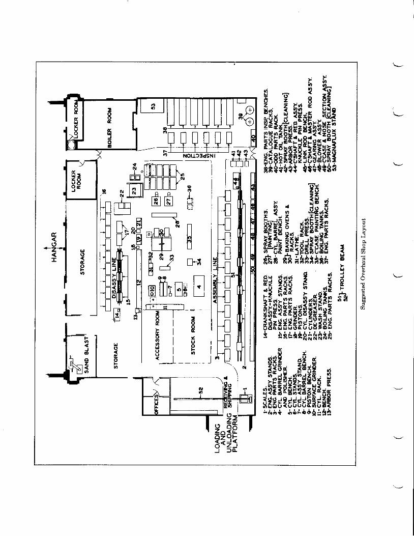
Suggested Overhaul Shop Layout
CHAPTER I
DISASSEMBLY OF ENGINE INTO MAJOR SUB-ASSEMBLIES Page
Fig. 101- Engine Overhaul Stand 102Fig. 102 - Loosening the Thrust Nut 102Fig. 103 - Checking Propeller Shaft Runout with Dial Indicator. . . 702Fig. 104 - Removal of Front Section (Geared Engines) I04Fig. 105 - Removal of Front Section (Direct Drive Engines) 104Fig. 106 - Removal of Reduction Drive Gear. . 104Fig. 107 - Removal of Front Half of Main Crankcase. 105Fig. 108 - Removal of Front Main Bearing Inner Race.. 106Fig. 109 - Removal of Crankshaft and Articulating Rod Assembly 106Fig. 110 - Removal of OiI Pump L07Fig. 111 - Removal of Gun Drive Gear. L07Fig. 112 - Separating Rear and Blower Sections 108
CHAPTER II
DISASSEMBLY OF MAJOR SUB-ASSEMBLIES
Fig. 201 - Removal of Pinion Cage Lock Nut. .Fig. 202 - Removal of Pinion Cage Assembly.Fig. 203 - Removal of Pinion ShaftsFig.204 - Use of the Valve Spring DepressorFig. 205 - Removal of Spring Blower Drive CouplingFig. 206 - Rernoval of Rear Main Bearing Inner Race.Fig.207 - Separating the Two Sections of the CrankshaftFig. 208 - Disassembly of Flyweight SectionsFig. 209 - Removal of Knuckle PinsFig. 210 - Use of the Blower Gear Holder. . . . .Fig. 211 - Removal of the Impeller Nut. .Fig.2L2 - Removal of the Impeller.Fig. 213 - Removal of Intermediate Shaft Rear Bearing and Inner Liner. . .Fig. 214 - Removal of Floating Gear Retaining Nut. .
CHAPTER III
CLEANING
Fig. 301__ Typical Engine Parts Wash Stand.
202202203203204205206206207207208209209209
302304Fig. 302 - Typical Engine Wash House.
CEAPTER IV
INSPECTION
Fig. 401 - Inspection of Propeller Shaft for ConcentricityFig. 402 - Use of Valve Stretch Gage.Fig. 403 - Spring Testing MachineFig. 404 - Inspection of Cylinders for Wear and Taper.Fig. 405 - Checking Side Clearance of Piston Rings. . .Fig. 406A-F - Leaded Silver Master Rod Bearings. . . . 412-4L7Fig. 407 - Inspection of Articulating Rods for Torsional Displacement. . . . . 4I8Fig. 408 - AN-484 Magnaflux Machine 421Fig. 409 - Demagnetizing Unit. . 422Fig. 410 - Magnetizing Articulating Rods. 426Fig. 411 - Magnetizing Reduction Gear Cage. 426Fig. 4L2 - Magnetizing Shelf Type Cam 426Fig. 413 - Magnetizing Cylinder in a Solenoid 427Fig. 4L4- Magnetizing Cylinder with Cable through Bore and Out Intake
Port. . 427Fig. 415 -- Magnetizing Reduction Drive GearFig. 416 - Magnetizing Knuckle Pin in a Solenoid. . .Fig. 4L7 - Magnetizing Valve Tappet Rollers on a RodFig. 418 - Magnetizing Valve Tappet Rollers in a Solenoid. . .Fig. 419 - Method of Holding Valve Tappet Rollers in Inspection Bath. . . .Fig. 420 - Magnetizing Propeller Shaft
CIIAPTER V
REPAIR AND ASSEMBLY OF MAJOR SUB-ASSEMBLIES
Fig. 500 - Typical Set-up for Metal SprayingFig. 501 - Installing Valve Tappet Guide - Wasp Jr.. . . . 505Fig. 502 - Reaming Valve Tappet Guide - Wasp Jr.. . . 505Fig. 503 - Reaming Governor Driven Gear Bushing - Wasp H1. . . 506Fig. 504 - Reaming the Intermediate Governor Drive Gear Bushing -
Wasp Hl. .Fig. 505 - Reaming Cam Reduction Gear Bushing - Wasp H1-GFig. 506 - Grinding Fixed Gear Ring SurfaceFig. 507 - Boring Pinion Gear Bushing. . . .Fig. 508 - Reoperation of Propeller Shaft Threads. . .Fig. 509 - Removing Cam Reduction Gear Bushing. . . .Fig. 510 - Installing Mounting Disc for Name Plate on Sump.Fig. 511 - Drilling Out Valve Guide.Fig. 512 - Reaming Valve Guide 515Fig. 513 - Removal of Inlet Valve Seat - Boring. 515Fig. 514 - Facing Valve Seat. .Fig. 515 - Refacing ValveFig. 516 - Reaming Rocker Shaft Inserts. . . .Fig. 517 - Removing Rocker Arm Ball Cup. .Fig. 518 - Removing Push Rod Ball End. .Fig. 519 - Lapping Cylinder Barrel Flange.Fig. 520 - Valve Tappet Reworking.Fig. 5204' - Piston Ring Arrangements (Wasp Jr. Engines)Fig. 5208 - Piston Ring Arrangements (Wasp and Hornet Engines)Fig. 521 - Checking End Clearance of Piston Ring. .
Page
404406407408409
i
427427428428428428
5085085095105105t25135L4
516516518519519520520521522523
I
CEAPTER V (contlnued)
REPAIR AND ASSEMBLY OF MAJOR SUB-ASSEMBLIES (continued) Page
Fig.522 - Cylinder and Piston Ring Lapping Machine. 524Fig. 523 - Installation of Master Rod Bearing. . . . . 526Fig. 524 - Methods of Plugging and Taping Knuckle Pins Before Plating.. . 527Fig. 525 - Installing Piston Pin BushinC. . . . . 528Fig. 526 - Pinning the Piston Pin BushinC. . . . . 529Fig.527 - Wadell Boring Fixture - Articulating Rod. 530Fig. 528 - Removing Oil Pressure Pipe from Rear Section.Fig. 529 - Reaming Magneto Shaft Bushing. . . .Fig. 530 - Facing Magneto Shaft Bushing.. . .Fig. 531 - Reaming Starter Shaft Bushing. . . .Fig. 532 - Assembly of Pinion Shafts into Cage.Fig. 533 - Assembly of Pinion Cage on Propeller Shaft.Fig. 534 - Installing Rocker Arm Bearing. . . . .Fig. 535 - Installing Knuckle Pins in Master Rod. .Fig. 536 - Section of Master Rod Showing Knuckle Pins and Lock.Fig. 537 - Assembly of Crankshaft.Fig. 538 - Diagram Showing Direction of Thrust of Impeller Shaft and
Intermediate Shaft Bearings - Steel Cage TypeFig. 539 - Diagram Showing Direction of Thrust of Impeller Shaft and
Intermediate Shaft Bearings - Outboard Support Type.Fig. 540 - Assembly of Impeller with the PusherFig. 541- Checking Clearance Between Impeller and Blower Case. .Fig. 542 - Blower Bearing Cover Assembly Showing Location of Securing
Screws.Fig. 543 - Checking Clearance Between O.D. of Spacer and I.D. of Blower
Bearing Cover Hole..
CEAPTER VI
FINAL ASSEMBLYFig. 601- Checking Starter Shaft Bushing with Flush Pin GageFig. 602 - Checking Backlash between Generator Drive Gear and Starter
Jaw GearFig. 603 - Checking Backlash between Vacuum Pump Drive Gear and
Fuel Pump Drive Gear. .Fig. 6034' - Vacuum Pump Gaskets.Fig. 604 - Checking Clearance between Bottom of Cam Spacer and Top of
Cam Hub - Wasp Jr. Engine.Fig. 605 - Installing Reduction Drive Gear.Fig. 606 - Installing Cylinder.Fig. 607 - Installing OiI SumpFig. 608 - Timing Marks on Scintilla SB-9R MagnetoFig. 609 - Timing Pointer for Timing and Synchronizing Magnetos.Fig. 610 - Rear View of American Bosch SB9RU-3 Magneto Showing
Timing MarksFig. 611- Wiring Diagram.
CHAPTER VII
RUN.IN OF ENGINES AFTER OVERHAUL
Fig. 701 - Typical Engine Test Chamber.
53153253353453753854054054L541
542
542543544
545
546
602
602
603604
605606607608610610
6116LL
702704Fig.702 - Adapter Mount Plate for Single Row Engines.

CHAPTER VII (conttnued)
RUN-IN OF ENGINE AFTER OVERHAUL (continued)
Fig. 703 - Typical Control RoomFig. 704 - Piping Diagram of Typical Test House
7067L07137147167t8
Fig. 705 - Typical Installation Drawing-Wasp Jr. 83.Fig. 7054' - Typical Installation Drawing-Wasp S3H1.Fig. 706 - Sample Log of Engine TestFig. 707 - Psychrometric Vapor Pressure Chart
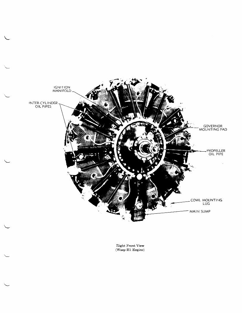
I G N I T I O NM A N I F O L D
I N T E R - C Y L I N D E RO I L P I P E S
1-- owl MoIJNTING
GOVERNORMOUNTING PAD
PROPELLERO I L P I P E
MAIN SUMP
Right Front View(Wasp H1 Engine)
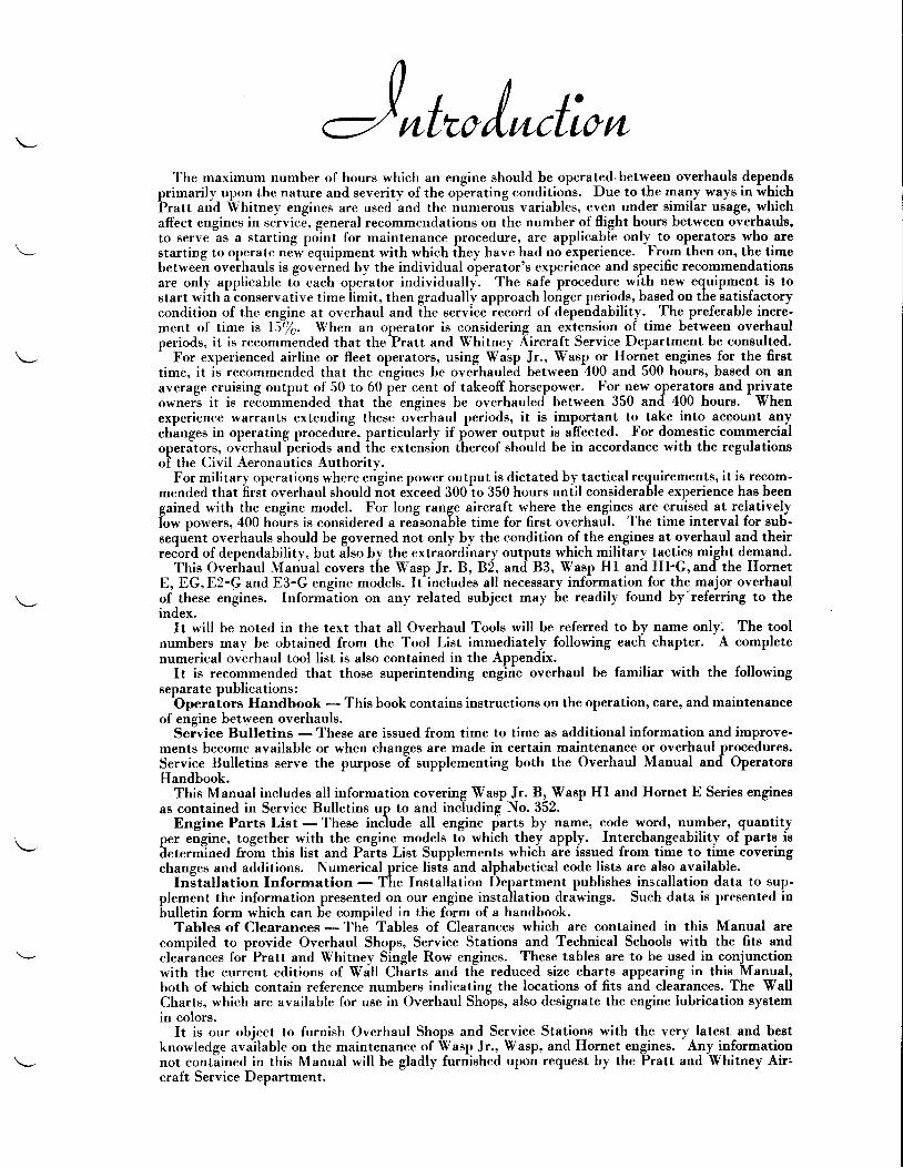
J*t r/*ctioruThe maximum number of hours which an engine should be operated'between overhauls depends
primarily upon the nature and severity of rhe op-erating conditions. Due to the many ways in ihichPratt and Vhitney engines are used and the riumeto,ls variables, even under similar ueage, whichaffect engines in service, general recommendations on the number of flight h_ours between overhaula,to serve as a starting point for maintenance procedure, are applicable only_to operators who arestarting to operate nJw'equipment with which ihey have had nd&perience.
-Fromihen on, the time
between oveihauls is governid by the individual operatoros experience and sp_ecific recommendationeare only applicable t6 each opeiator individually^. The safe procedure_with new equipment is tostart with a
-conservative time limit, then graduallv approach longer periods, based on the satisfactory
condition of the engine at overhaul and ihe .".rni""i""o.d of d6pendability. The preferable incre-ment of time is lS-/e. When an operator is considering an ext_ension of time between overhaulperiods, it is recommended that the?ratt and Vhitney Aircraft Service Department be consulted.-
For experienced airline or fleet operators, using Wasp Jr., Wasp or Hornet errgines-for the firettime, it ii recommended that the engines be oveihaul"h betlne"n 400 and 500 hours, baeed on anaverage cruising output of 50 to 60 per cent of takeoff horsepower. For new operl-tors and privateowner"s it is reiommended that the engines be overhaul"d between 350 and 400 hours.
- Vhen
experience warrants extending these ov-erhaul periods, it is important to take into account anychinges in operating proceduri, particularly if power output is affected. For domestic commercialop.r""to.r, overha"lllriods and ihe e*tensi,on thereof should be in accordance with the regulationsof the Civil Aeronautics Authoritv.
For military operations where engine power output is dictated by tactical requirements, it is recom-mended that frrs't overhaul should iot eiceed 300io 350 hours uniil considerable experience has beengained with the engine model. For long range aircraft where the engines are cruised at relativelyiorn po*.r.. 400 hoirs is considered a reisonable time for first overhaul. The time interval for sub-sequent overhauls should be governed not only by the condition of the engines at overhaul and theirrecord of dependabil ity, but i lso by the extraordinary outputs which military tactice might demand.
This Oveihaul Manual covers tLe Wasp Jr.B,Bi, "ttd'83, Wasp Hl "niHl-G,and-the HornetE, EG,E2-GandE3-Gengine models. It^includes all necessary information for the major overhaulof these engines. Informition on any related subject may be readily found by-referring to theindex.
It will be noted in the text that all Overhaul Tools will be referred to by name only. The toolnumbers may be obtained from the Tool List immediately following each chapter. A completenumerical overhaul tool l ist is also contained in the Appendix.
It is recommended that those superintending engirie overhaul be familiar with the followingseparate publications :-Operators
Handbook - This book contains instructions on the operation, care, and maintenanceof engine between overhauls.
Seivice Bulletins - These are issued from time to time as additional information and improve-ments become available or when changes are made in certain maintenance or overhaul procedurea.Service Bulletins serve the purpose oT supplementing both the Overhaul Manual and OperatorBHandbook.
This Manual includes all information covering Vasp Jr. B, Wasp Hl and Hornet E Seriee enginesas contained in Service Bulletins up to and including No. 352.
Engine Parts List - These inciude all engine iarts by name, code word, numbero quantityper eigine, together with the engine models t6 which they apply. Interchangeability of parte iideterm-ined from this list and Paits List Supplements which are issued from time to time coveringchanges and additions. Numerical price lisfs and alphabetical code lists are also available.
Installation Information - The Installation Department publishes installation data to sup-plement the information presented on our engine installation drawings. Such data is presented inbulletin form which can be compiled in the form of a handbook.
Tables of Clearances - The Tables of Clearances which are contained in this Manual arecompiled to provide Overhaul Shops, Service Stations and Technical Schools with the fits andcleaiances fof Pratt and Whitney Single Row engines. These tables are to be used in conjqnctionwith the current editions of Wdll Chlrts and the reduced size charts appearing in this Manual,both of which contain reference numbers indicating the locations of fits and clearances. The WallCharts, which are available for use in Overhaul Shopso also designate the engine lubrication Eyetemin colors.
It is our object to furnish Overhaul Shops and Service Stations with the very latest and beetknowledge available on the maintenance of Wasp Jr.,, Wasp, and Ho_rnet_engines. Any informationnot contained in this Manual will be gladly furnished upon request by the Pratt and Whitney Air.craft Service Department.
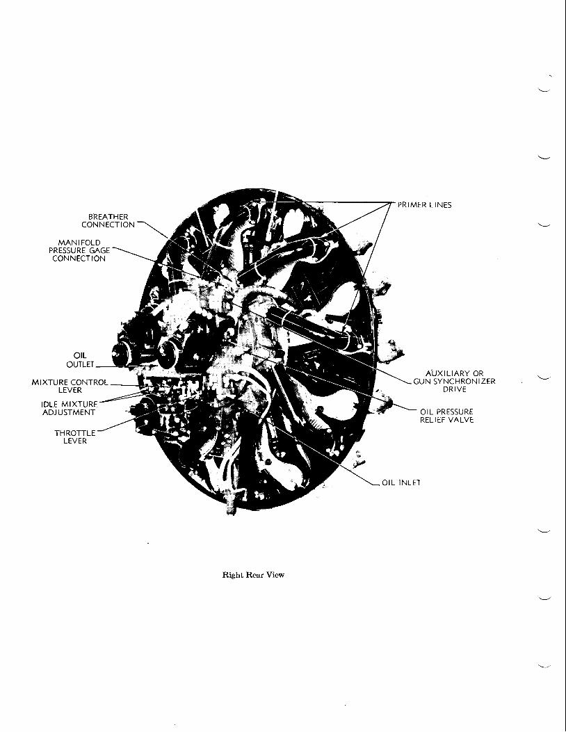
MANIFOLDPRESSURE GAGECONNECTION
MIXTURE CONTROLLEVER
IDLE MIXTUREADJUSTMENT
THROTTLELEVER
olLOUTLET
P R I M E R L I N E S
AUXIL IARY ORGUN SYNCHRONIZER
D R I V E
OIL PRESSURERELIEF VALVE
O I L I N L E T
Right Rear View
BREATHERCONNECTION
Authorized ServiceService Stations.
s t R v l c tStations - The emblem illustrated below is
AUTHORIZED
displayed by Authorized
PARTS & SERYICEAll stations displaying this sign have equipment and personnel for thoroughly and efficiently
overhauling Pratt and Whitney engines. Thege stations use only Pratt and Whitney Aircraft partswhich are iotd at the publishei ""i'"log prices at all Service Staiions throughout the United Sfatee.
Factory Service Department - Pratt and Whitney Aircraft maintains a Factory ServiceDepartment to assiet its customers in the operation and maintenance of Pratt and Whitney Air-crait engines. The Service Department maintains contact with Operatorg and Overhaul activitieeby mearis of periodic visite of s6rvice representativeso who are also ivailable for the investigation ofairy specific difficulty or problem. Any request for assistance should be addressed direit to theSeivicl,s Department of thi Pratt and Whitnev Aircraft, East Hartford, Connecticut.
Ordering Parts - Whenever possible, parts should be ordered from a Parts Catalog. Thesecatalogs arJfurnished to Operatoriand Serv'ice Stations and are available to other intereste? parties.In casi a parts list ie not av'ailable, give name of engine, modelo and engine number, and a full descrip-tion of the part wanted and where it is used. Whenever possible, parts should be ordered throughthe neareet Service Station.
Some parts are not furnished individually but must be purchased as assemblies. This is becaueethey require special or expensive equipment for assembling and cannot be fabricated except in aehop especially equipped for thie work. If an order is received for a unit of an assembly comingunder this classification, the complete assembly will be shipped.
Spare parts for carburetors, magnetos and special radio shielding together with such accessoriesae propellers, hubso vacuum pumps, starters, generators, should be ordered direct from the manu-facturer.
Returning Parts - Whenever possibleo parts being returned for repairso information, inspectionor credit, ehould be returned through an authorized Service Station. In caee it is not possible tosend parts in through an authorized Service Stationo it is necessary to first obtain the prop"i authorityfrom the factory for their return. When requesting authority fol return of parts or when returningparts to a Service Station all information should be given as to:
l. Reason for return. 3. Type of engine from which parts are taken.2. Engine Number. 4. Number of hours of service of the part and of the engine.
If the parts are being returned direct to the factory, proper notification of shipment must be sentto the factory so that it will arrive at least one day in advance of the receipt of parts...
When returning parts for repair only, it is unnecessary to obtain authority for return and, whereasdesirable, it is not essential to have them sent through a Service Station. All factory repair work ishandled by the United Airports Divieion, RentschlEr Field, East Hartford, Conn.' Strictly repairiteme ehould be sent to that address.
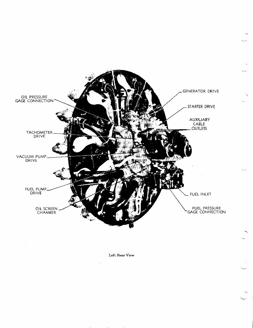
OIL PRESSUREGAGE CONNECTION
TACHOMETERD R I V E
VACUUM PUMPD R I V E
FUEL PUMPDRIVE
GENERATOR DRIVE
STARTER DRIVE
AUXILIARYCABLE
OUTLETS
FUEL INLET
FUEL PRESSUREGAGE CONNECTION
OIL SCREENCHAMBER
Left Rear View
SUGGESTED SPECTAL EQUTPMENT FOR OVERHAUL SEOP
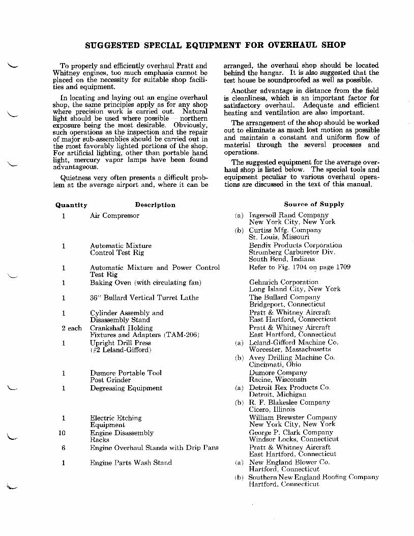
To properly and efficiently overhaul Pratt andWhitney engines, too much emphasis cannot beplaced on the necessity for suitable shop facili-ties and equipment.
In locating and laying out an engine overhaulshop, the same principles apply as for any shopwhere precision work is carried out. Naturallight should be used where possible - northernexposure being the most desirable. Obviously,such operations as the inspection and the repairof major sub-assemblies should be carried out inthe most favorably lighted portions of the shop.For artificial lighting, other than portable handlight, mercury vapor lamps have been foundadvantageous.
Quietness very often presents a difficult prob-lem at the average airport and, where it can be
Quantlty I)escrlptlon
1 Air Compressor
I
2 each
1
Automatic MixtureControl Test Rig
Automatic Mixture and Power ControlTest RigBaking Oven (with circulating fan)
36" Bullard Vertical Turret Lathe
Cylinder Assembly andDisassembly StandCrankshaft HoldingFixtures and Adapters (TAM-206)Upright Drill Press(rt2 Leland-Gifford)
Dumore Portable ToolPost GrinderDegreasing Equipment
Electric EtchingEquipmentEngine DisassemblyRacksEngine Overhaul Stands with Drip Pans
Engine Parts Wash Starid
arranged, the overhaul shop should be locatedbehind the hangar. It is also suggested that thetest house be soundproofed as well as possible.
Another advantage in distance from the fieldis cleanliness, which is an important factor forsatisfactory overhaul. Adequate and efficientheating and ventilation are also important.
The arrangement of the shop should be workedout to eliminate as much lost motion as possibleand maintain a constant and uniform flow ofmaterial through the several processes andoperations.
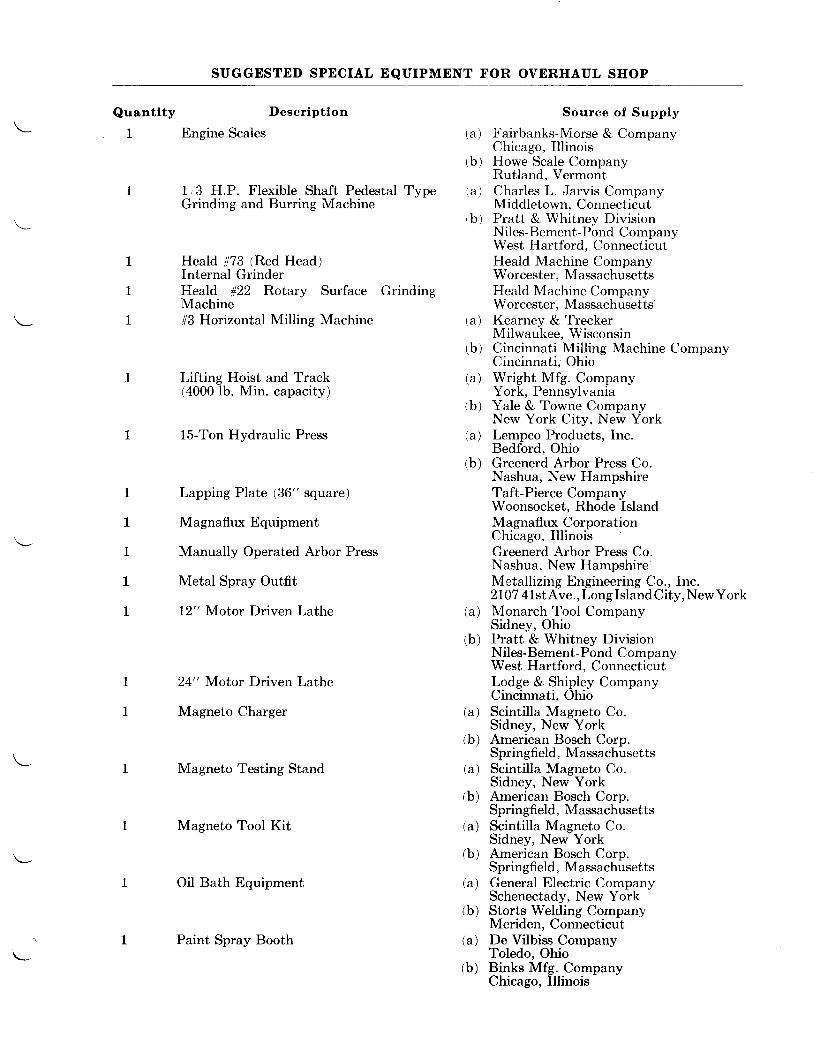
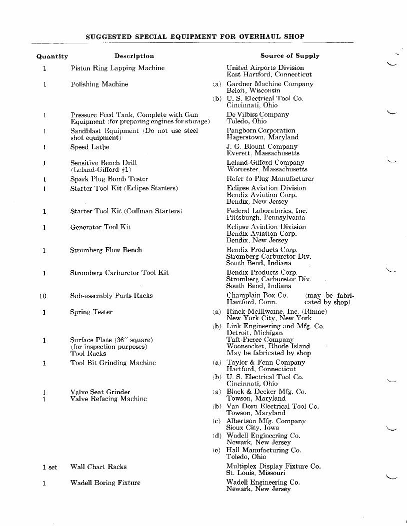
The suggested equipment for the average over-haul shop is listed below. The special tools andequipment peculiar to various overhaul opera-tions are discussed in the text of this manual.
Souree of Supply
Ingersoll Rand CompanyNew York City, New YorkCurtiss Mfg. CompanySt. Louis, MissouriBendix Products CorporationStromberg Carburetor Div.South Bend, IndianaRefer to Fig. 1704 ol page 1709
Gehnrich CorporationLong Island Oity, New YorkThe Bullard CompanyBridgeport, ConnecticutPratt & Whitney AircraftEast Hartford, ConnecticutPratt & Whitney AircraftEast Hartford, ConnecticutLeland-Gifford Machine Co.Worcester, MassachusettsAvey Drilling Machine Co.Cincinnati, OhioDumore CornpanyRacine, WisconsinDetroit Rex Products Co.Detroit, MichiganR. F. Blakeslee CompanyCicero, IllinoisWilliam Brewster CompanyNew York City, New YorkGeorge P. Clark CompanyWindsor Locks, ConnecticutPratt & Whitney AircraftEast Hartford, ConnecticutNew Bngland Blower Co.Hartford, ConnecticutSouthern New England Roofing CompanyHartford, Connecticut
( a i
(b )
1
1
1
( a )
(b )
( a )
(b)
1
10
6
1 ( a )
( b )
\-
>1
rl
a
Ia
a0)q000
ct)
H e I 3 ro = o Y z
Fp,, i Ag-; -*
fiilnHillillfiligu
o u ; E E , $
Flisi;;fifiifi
5
TFllL-'l
lI-"4
t!(,E
Io {i
t..tgE1 oE F' c
! fJct86+,hN N
d2fo
Hrl:fii:!;fr!aPtl*dTTHHHi {Er
G
*fififi**fiuifi*.rt*llelli;FH;fiE*&.tr+ 66*5AAi{ i
rDo,P'\D
r ( \ d lt r t t
.#t +
sgQ O
l o l |F ll a l l Q l
tldo
!lJ
II
{ ' t 6
d.
I*z-I
{ { * * * *
lEtI
r ( ,
zo
24< 4
(,zooJ
NOlJ.f,3dSNl
IR n Iis+ryq H I
I T I U IflV !'-; IF ' � ' I- s e
Ih l . t t l
F-" LII blt tIJ iF_*__lS i s lfr I F I
_ q _i__i__i
Eiil \^[:]l a
€' l*LJflJ'Pil T--n
9 E I T I1 i l f f * gt l t l . + . /
l l l H -l l l - o ogl ffi r-r,
I II H LI.JI E]iI ll i'lA-{-ti:r--=----JF I T Ie l 8 i
l c lt > lI t r lt ol o � ll o ll L J lt u lt u iL _ < _ r _
-'a rd
)9o
SUGGESTED SPECIAL EQUIPMENT FOR OVERHAUL SHOP
Quantlty
1
Descrlptlon
Engine Scales
1,,3 H.P. Flexible Shaft Pedestal TypeGrinding and Burring Machine
Heald #73 (Red Head)Internal GrinderHeald #22 Rotary Surface GrindingMachine#3 Horizontal Milling Machine
Lifting Hoist and Track(4000 lb. Min. capacity)
15-Ton Hydraulic Press
Lapping Plate (36" square)
Magnaflux Equipment
Manually Operated Arbor Press
Metal Spray Outfit
12" Motor Driven Lathe
24" Motor Driven Lathe
Magneto Charger
Magneto Testing Stand
Magneto Tool Kit
Oil Bath Equipment
Paint Spray Booth
Source of Supply
Fairbanks-Morse & CompanyChicago, IllinoisHowe Scale CompanyRutland, VermontCharles L. Jarvis CompanyMiddletown, ConnecticutPratt & Whitney Divis ionNiles-Bement-Pond CompanyWest Hartford. ConnecticutHeald Machine CompanyWorcester, MassachusettsHeald Machine CompanyWorcester, MassachusettsKearney & TreckerMilwaukee, WisconsinCincinnati Milling Machine CompanyCincinnati, OhioWright Mfg. CompanyYork, PennsylvaniaYale & Towne CompanyNew York City, New YorkLempco Products, Inc.Bedford, OhioGreenerd Arbor Press Co.Nashua, New HampshireTaft-Pierce CompanyWoonsocket, Rhode IslandMagnaflux CorporationChicago, IllinoisGreenerd Arbor Press Co.Nashua, New HampshireMetallizing Engineering Co., Inc.2107 41stAve., Long Island City, NewYorkMonarch Tool CompanySidney, OhioPratt & Whitney DivisionNiles-Bement-Pond CompanyWest Hartford, ConnecticutLodge & Shipley CompanyCincinnati, OhioScintilla Magneto Co.Sidney, New YorkAmerican Bosch Corp.Springfield, MassachusettsScintilla Magneto Co.Sidney, New YorkAmerican Bosch Corp.Springfield, MassachusettsScintilla Magneto Co.Sidney, New YorkAmerican Bosch Corn.Springfield, MassachusettsGeneral Electric CompanySchenectady, New YorkStorts Welding CompanyMeriden, ConnecticutDe Vilbiss CompanyToledo, OhioBinks Mfg. CompanyChicago, Illinois
( a )
(b )
( a )
r b )
( a )
(b )
( a )
(b )
(a)
(b)
(a )
(b )
(a)
(b)
(a )
(b )
( a )
(b )
( a )
rb)
(a)
(b)
SUGGESTED SPECIAL EQUIPMENT FOR OVERHAUL SHOP
Quantity Description
1 Piston Ring Lapping Machine
1 Polishing Machine
1 set
1
Pressure Feed Tank, Complete with GunEquipment {for preparing engines for storage)
Sandblast Equipment (Do not use steelshot equipment)Speed Lathe
Sensitive Bench DrilllLeland-Gifford #1)Spark Plug Bomb Tester
Starter Tool Kit (Eclipse Starters)
Starter Tool Kit (Coffman Starters)
Generator Tool Kit
Stromberg Flow Bench
Stromberg Carburetor Tool Kit
Sub-assembly Parts Racks
Spring Tester
Surface Plate (36" square)ifor inspection purposes)Tool RacksTool Bit Grinding Machine
Valve Seat GrinderValve Refacing Machine
Wall Chart Racks
Wadell Boring Fixture
Source of Supply
United Airports DivisionEast Hartford, ConnecticutGardner Machine CompanyBeloit, WisconsinU. S. Electrical Tool Co.Cincinnati, OhioDe Vilbiss CompanyToledo, OhioPangborn CorporationHagerstown, MarylandJ. G. Blount CompanyEverett, MassachusettsLeland-Gifford CompanyWorcester, MassachusettsRefer to Plug ManufacturerEclipse Aviation DivisionBendix Aviation Corp.Bendix, New JerseyFederal Laboratories, Inc.Pittsburgh, PennsylvaniaEclipse Aviation DivisionBendix Aviation Corp.Bendix, New JerseyBendix Products Corp.Stromberg Carburetor Div.South Bend, IndianaBendix Products Corp.Stromberg Carburetor Div.South Bend, Indiana
Champlain Box Co. (may be fabri-Hartford, Conn. cated by shop)Rinck-Mclllwaine, Inc. (Rimac)New York City, New YorkLink Engineering and Mfg. Co.Detroit, MichiganTaft-Pierce CompanyWoonsocket, Rhode IslandMay be fabricated by shopTaylor & Fenn CompanyHartford, ConnecticutU. S. Electrical Tool Co.Cincinnati, OhioBlack & Decker Mfg. Co.Towson, MarylandVan Dorn Electrical Tool Co.Towson, MarylandAlbertson Mfg. CompanySioux City, IowaWadell Engineering Co.Newark, New JerseyHall Manufacturing Co.Toledo, OhioMultiplex Display Fixture Co.St. Louis, MissouriWadell Engineering Co.Newark. New Jersev
( a )
(b )
10
(a )
(b )
t a )
(b)
(a )
(b)
(c)
(d )
(e)
REMOVAL OF ENGINE FROM AIRPLANE
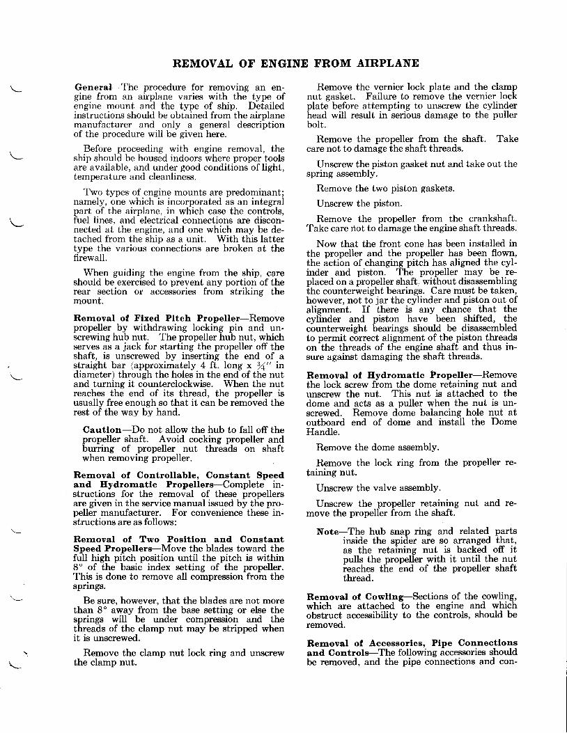
General-The procedure for removing an en-gine from an airplane varies with the type ofengine mount and the type of ship. Detailedinstructions should be obtained from the airplanemanufacturer and only a general descriptionof the procedure will be given here.
Before proceeding with engine removal, theship should be housed indoors where proper toolsare available, and under good conditions oflight,temperature and cleanliness.
Two types of engine mounts are predominant;namely, one which is incorporated as an integralpart of the airplane, in which case the controls,fuel lines, and electrical connections are discon-nected at the engine, and one which may be de-tached from the ship as a unit. With this lattertype the various connections are broken at thefirewall.
When guiding the engine from the ship, careshould be exercised to prevent any portion of therear section or accessories from striking themount.
Removal of Flxed Pttch Propeller-Removepropeller by withdrawing locking pin and un-screwing hub nut. The propeller hub nut, whichserves as a jack for starting the propeller off theshaft, is unscrewed by inserting the end of astraight bar (approximately 4 ft. long x /a" indiameter) through the holes in the end of the nutand turning it counterclockwise. When the nutreaches the end of its thread, the propeller isusually free enough so that it can be removed therest of the way by hand.
Cautlon-Do not allow the hub to fall off thepropeller shaft. Avoid cocking propeller andburring of propeller nut threads on shaftwhen removing propeller.
Rernoval of Controllable, Constant Speedand Eydrornatlc Propellers-Complete in-structions for the removal of these propellersare given in the service manual issued by the pro-peller manufacturer. For convenience these in-structions are as follows:
Rernoval of Two Posltlon and ConstantSpeed Propellers-Move the blades toward thefull high pitch position until the pitch is within8" of the basic index setting of the propeller.This is done to remove all compression from thesprings.
Be sure, however, that the blades are not morethan 8o away from the base setting or else thesprings will be under compression and thethreads of the clamp nut may be stripped whenit is unscrewed.
Remove the clamp nut lock ring and unscrewthe clamp nut.
Remove the vernier lock plate and the clampnut gasket. Failure to remove the vernier lockplate before attempting to unscrew the cylinderhead will result in serious damage to the pullerbolt.
Remove the propeller from the shaft. Takecare not to damage the shaft threads.
IJnscrew the piston gasket nut and take out thespring assembly.
Remove the two piston gaskets.
IJnscrew the piston.
Remove the propeller from the crankshaft.Take care rlot to damage the engine shaft threads.
Now that the front cone has been installed inthe propeller and the propeller has been flown,the action of changing pitch has aligned the cyl-inder and piston. The propeller may be re-placed on a propeller shaft. without disassemblingthe counterweight bearings. Care must be taken,however, not to jar the cylinder and piston out ofalignment. If there is any chance that thecylinder and piston have been shifted, lhgcbunterweight bearings should be disassembledto permit correct alignment of the piston threadson'the threads of tlie engine shaff and thus in-sure against damaging the shaft threads.
Rernoval of Hydrornatle Propeller-Removethe lock screw from the dome retaining nut andunscrew the nut. This nut is attached to thedome and acts as a puller when the nut is un-screwed. Remove dome balancing hole nut atoutboard end of dome and install the DomeHandle.
Remove the dome assembly.
Remove the lock ring from the propeller re-taining nut.
Unscrew the valve assembly.
Unscrew the propeller retaining nut and re-move the propeller from the shaft.
Note-The hub snap ring and related partsinside the spider are so arranged that,as the retaining nut is backed off itpulls the propeller with it until the nutieaches the end of the propeller shaftthread.
Removal of Cowllng-Sections of the cowling,which are attached to the engine and whichobstruct accessibility to the controls, should beremoved.
Removal of Accessories, Plpe Connectlonsand Controls-The following accessories shouldbe removed, and the pipe connections and con-\
REMOVAL OF ENGINE FROM AIRPLANE
trols disconnected prior to removal of enginefrom the airplane:
1. Battery.2. Throttle control rods (on side of carbu-
retor).3. Mixture control rods (on side of carbu-
retor behind throttle).4. Starter energizing rod (if provided).5. Governor control linkage (if provided).6. Hot air control rod (on air intake).7. Oil inlet pipe connection (at right side of
rear section below oil pump).8. Oil outlet pipe connection (at rear center
of engine).9. Oil outlet temperature gage connection.
10. Oil pressure gage pipe.11. Oil tank vent pipe.12. Carburetor fuel supply pipe (at left side
of carburetor).13. Fuel pressure gage pipe (at left or"rear
side of carburetor).L4. Fuel pressure relief pipe.15. Fuel pump inlet and outlet pipes.16. FueI pump drain pipe.L7. Manifold pressure gage pipe.18. Wiring from magnetos to switch.19. Thermocouplewiring.20. Tachometer cable.2L. Exhaust pipes to hotspot (if provided).22. Exhaust manifold and pipes.23. Carburetor air scoop (below carburetor).24. Generator, if provided (it is necessary
that all external wire connections be firstdisconnected).
25. Starter.26. Carburetor.27. Vacuum pump.28. Any other accessories, piping or wiring
attached thereto, which might interferewith removal of an engine.
Rernoval of Englne frorn Alrplane-Hook theLifting Sling, PWA-37, to a chain hoist and thesling to the lifting links provided at the top of theengine, and then relieve mount of engine weight.
Remove the engine mounting bolts, startingwith those at the bottom and concludine with thetop bolt.
Caution-Two men are required for thisoperation, one to remove the mounting boltsand one to operate the chain hoist.
Cover portions of the rear section and acces-sories which may strike the mount, and thencarefully remove engine from mount. Lower theengine and fasten it to the upturned mountingflange of an engine stand using six V16" bolts.
The engine is now ready for the overhaul shop.When received in the overhaul shop, an inspec-tion and record should be made of the conditionof the engine and its equipment.
Rernoval of Englne frorn Packlng Box-Theengine may be removed from its packing box byattaching the Lifting Sling, PWA-37, to the lift-ing links provided at the top of the engine, andsupporting the engine from a chain hoist. Thebox should be tilted on its side so the engineis in a horizontal (flight) position. Proceed in amanner similar to that indicated under the head-ing "Removal of Engine from Airplane."
Cautlon-When tilting the box and engine,gradually take up the weight with the hoistto avoid danger of tipping over. Care shouldbe taken that the arms of the Lifting Slingdo not damage the upper cylinders and ad-jacent parts.
The engine may also be removed from thepacking box in an upright (propeller shaft up)position by removing the thread protector on theend of the propeller shaft, attaching the properengine Lifting Eye, and using a chain hoisthooked to the Lifting Eye.
Support the engine weight by the hoist, removethe bolts securing the blower section to the platein the box, and carefully guide the engine fromthe plate while lifting it with the hoist. Theengine should then be placed on an engine standand fastened with at least six bolts.
The carburetor and other accessories should beremoved from their compartments in the packingbox.
\-
101
CEAPTER I
DISASSEMBLY OF ENGINE INTO MAJOR SUB-ASSEMBLIES
PRELIMINARY INSTRUCTIONS AND OPERATIONS
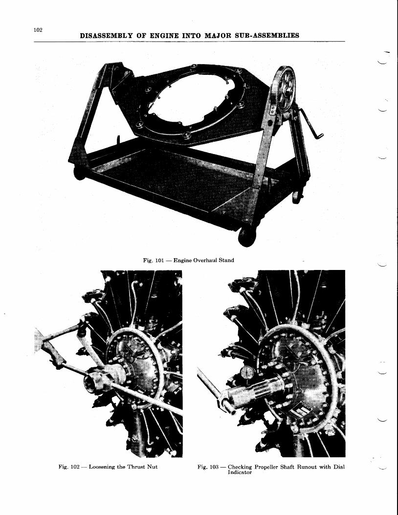
Before proceeding with the dismantling opera-tions as outlined in this chapter, the engineshould be mounted on an Engine Overhaul Stand(see Fig. 101). This is best accomplished byattaching a Lifting Eye to the end of the propellershaft and raising the engine onto the stand with alifting hoist having a minimum capacity of oneton. Fasten the engine to the stand with atleast six bolts through the mounting bolt holesin the blower section.
The dismantling instructions which follow arewritten with the understanding that all safetywiring, palnuts and cotter pins will be removedwhere necessary before attempting to disassem-ble any part from the engine.
For preliminary steps in engine disassembly,the.engine stand should be turned so that theengine assumes a horizontal (or flight) position.The procedure outlined in the following para-graphs is suggested.
Oil Dratn Plugs-Remove the plug at the bot-tom of the oil screen chamber in the rear sectionwith the Oil Screen Cover Wrench, and lift outthe oil screen and check valve assembly. Also,remove the oil drain plug from the bottom of thesump. Allow the oil to drain from the oil screenchamber and from the sump into suitable recepta-cles.
At this time it is advisable to examine thescreen, the sump drain plug and the oil for thepresence of any metal chips or foreign matterwhich would indicate a failure or some otherunsatisfactory condition in the engine.
Magnetos and Attachlng Parts-Removemagheto spark control rods, if provided. Re-move bolts, and unfasten clamps which attachmagneto shields to the magneto. Then removethe- shields and distributor blocks. Both setsof magneto distributor blocks should be pro-tected with heavy paper or cloth.
Remove cap screws which secure magnetos tothe rear section and lift off each magneto with itsrespective rubber coupling.
Magneto Coupllng Gear Screws-Loosen but
do not remove screws which fasten magnetocoupling gears to the rear ends of the magnetodrive shafts.
Cautlon-The screw driver used for thisoperation should fit snugly into the slots ofthe screws. If the screw driver is too small itwill damage the screw slots.
Starter-Unscrew nuts which fasten starter torear section and remove starter.
Starter Jaw Nut-Loosen but do not removenut which fastens starter jaw to the rear end ofthe starter shaft.
Gun Synchronlzers or Accessory Pumps-(Inscrew the nuts which fasten them to rearsection and remove. This procedure will applyto the removal of gun or pump drive covers ifthese parts are installed.
Vertlcal Accessory l)rlve Shaft-Loosen butdo not remove nuts on the upper ends of thevertical accessory drive shafts.
The engine should then be turned with thestand so that the propeller sllaft is in an uprightvertical position and the rear section is nearestthe floor.
Tachometer Drlve-Unscrew fillister headscrews which secure tachometer couplings to therear section and remove couplings and shafts.Thrust Bearlng Nut-In order to facilitatelater removal of the thrust bearing nut, loosen itone quarter turn using the Thrust Nut Wrench(see Fig. L02).Ignltlon Wlres-Unfasten at spark plugs.
Spark Plugs-Remove spark plugs with theproper Spark Plug Wrench.
Propeller Shaft Run-out-Mount a dial indi-cator on a thrust bearing cover stud with theplunger resting on the propeller shaft (see Fig.103). The run-out should not exceed .005" and.015" (full lndlcator readlng) on the rear andfront cone seats respectively. In the event thatthese limits are exceeded, particular note shouldbe made for further investigation after the enginehas been completely disassembled.
DISMANTLING
Dismantle the engine as follows:
Prkner Llnes-Disconnect all primer lines atthe blower end and also at the cylinders to whichthey are attached. Unfasten clamps holdingthem to the intake pipes and withdraw each
primer line from the deflector through which itextends.
Cyltnder I)efleetors-Early Wasp Jr. B engineswere equipped with V-type inter-cylinder deflec-tors. These deflectors are secured to the cylin-
102DISASSEMBLY OF ENGINE INTO MAJOR SUB-ASSEMBLIES
Fig. 101 - Engine Overhaul Stand
%
Fig. L03 - Checking Propeller Shaft Runout with DialIndicator
Fig. 102 - Loosening the Thrust Nut
103DISASSEMBLY OF ENGINE INTO MAJOR SUB.ASSEMBLIES
ders by means of a butterfly clamp. To remove,unscrew the wing nuts which fasten the deflectorsto the clamps and remove the deflectors andclamps.
Later Wasp Jr. B, early Wasp H1 and H1-G,and Hornet E engines were equipped with boltedpressure type deflectors. To remove, unscrewlhe nuts holding the cylinder head deflectors tothe cylinders. Unbolt each from the adjacentdeflector and remove. LJnscrew wing nuts hold-ing the inter-cylinder deflectors to retainingclamps and remove clamps and deflectors.
The "latch type" pressure deflectors, the typeused on current engines, are removed in the samemanner as the "bolted type", except that inter-cylinder and cylinder head deflectors are detachedbv withdrawing the spring loaded clamps fromthe cylinder head deflectors.
On Wasp Jr. engines having either the "one
shot" or "automatic" type of valve lubrication,the oil supply pipe should be disconnected at theinter-cylinder tee-pipe of No. 1 cylinder and at theIubricator pump or "one shot" valve on the rearsection befbre the removal of the No. 1 cylinderhead deflector. Withdraw the pipe from thedeflector. On engines incorporating the "one
shot" system, it will also be necessary to discon-nect the oil supply pipe to No. 6 cylinder.
Intake Ptpes-Loosen the packing nuts at theblower section, using the Intake Pipe PackingNut Wrench. Remove the cap screw and nutsat the cylinder ends and remove the intake pipesfrom the engine.
Note-These pipes are made of thin gagealuminum and are easily damaged ifdropped.
Push Rods and Covers-LJnscrew the top andbottom push rod cover gland nuts, using thePush Rod Tube Gland Wrench. Remove theclamps which secure the spark plug conduitsto the push rod covers.
Rocker Box Covers-Remove the rocker boxcovers from each cylinder.
On the Wasp and Hornet engines, prior to theremoval of the two rocker box covers adjacentto the sump, the tee-pipe connecting to the sumpshould be disconnected and then the rocker capsand tee-pipe removed as a unit. The rockercaps may then be disconnected from the tee-pipe.
Turn the engine until the valve actuated by thepush rod to be removed is closed. Depress thevalve spring with the Rocker Arm Depressor andremove the push rod and cover.
Radlo Shteldtng-Unscrew bolts which fastenthe front and rear radio shielding manifolds tothe main crankcase section and lift off the twomanifolds. On some shielding, the union nut
joining the two sections of the rear manifoldshould be unfastened prior to removal from theengine.
Otl Suctlon Ptpes-Unscrew the nuts whichfasten the lower ends of these pipes to the rearof the sump and the upper ends to the right handside of the rear section. Then unfasten clampsand remove pipes.
Otl Surnp-Using the Oil Sump Nut Wrench,unscrew the four nuts securing the sump to theengine. Pull the sump from the engine, takingcare not to damage the oil pressure pipes whichfit into the sump on Wasp and Hornet engines.
Cyltnders and Plstons-Prior to the removalof cylinders, the wrap locks or hose clamps mustbe removed from the inter-cylinder lubricator ordrain pipes and the hose connection between thepipes slipped to one side.
The rnaster rod cyllnder should be the lastrernoved.. On Wasp Jr. and Wasp engines thisis No. 5 cylinder, and on Hornet engines it isNo. 7 cylinder.
Turn the crankshaft or propeller shaft with theCrankshaft Spline Wrench, until the piston ofthe cylinder to be removed is at the top of itsstroke.
Remove the cylinder hold-down nuts, using theCylinder Nut Wrench, and pull off each cylinder.Upon removal of each cylinder, it is recommendedthat the cylinder be placed on wood or in someappropriate carrier to prevent damage to thecooling fins and the bottom end of the barrel.
Push the piston pin from each piston and re-move the latter.
Note-If difficulty is experienced in pushingout a piston pin, the head of the pistonmay be slightly heated and then thepin tapped out, using a fiber drift.
Cautlon-When using a drift to drive out apiston pin, the articulating rod in which the pinis fitted should be supported to prevent dam-age to either the knuckle pin bushing or themaster rod bearing.
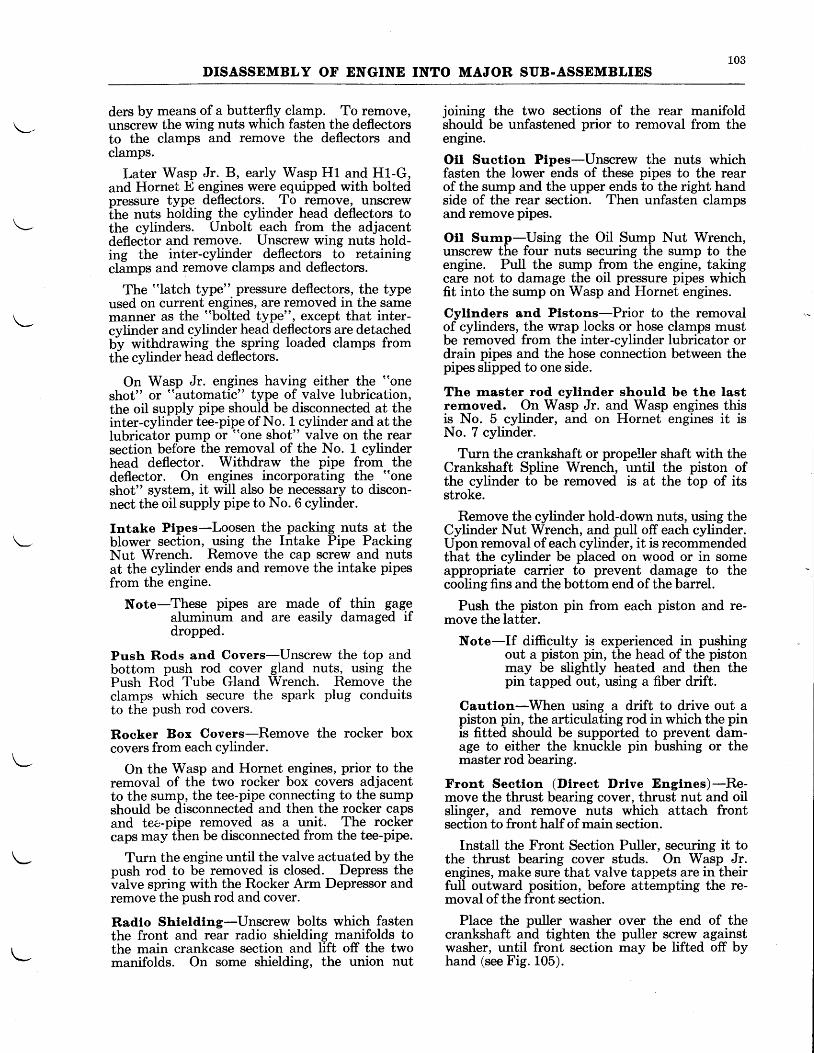
Front Sectlon (Dlrect l)rlve Englnes)-Re-move the thrust bearing cover, thrust nut and oilslinger, and remove nuts which attach frontsection to front half of main section.
Install the Front Section Puller, securing it tothe thrust bearing cover studs. On Wasp Jr.engines, make sure that valve tappets are in theirfull outward position, before attempting the re-moval of the front section.
Place the puller washer over the end of thecrankshaft and tighten the puller screw againstwasher, until front section may be lifted off byhand (see Fig. 105).
LO4DISASSEMBLY OF ENGINE INTO MAJOR SUB.ASSEMBLIES
L
13B ,
}
Fig. 104 - Removal of Front Section (Geared Engines)
Fig. 105 - Removal of Front Section (Direct DriveEngines)
Fig. 106 - Removal of Reduction Drive Gear
105
DISASSEMBLY OF ENGINE INTO MAJOR SUB-ASSEMBLIES
l
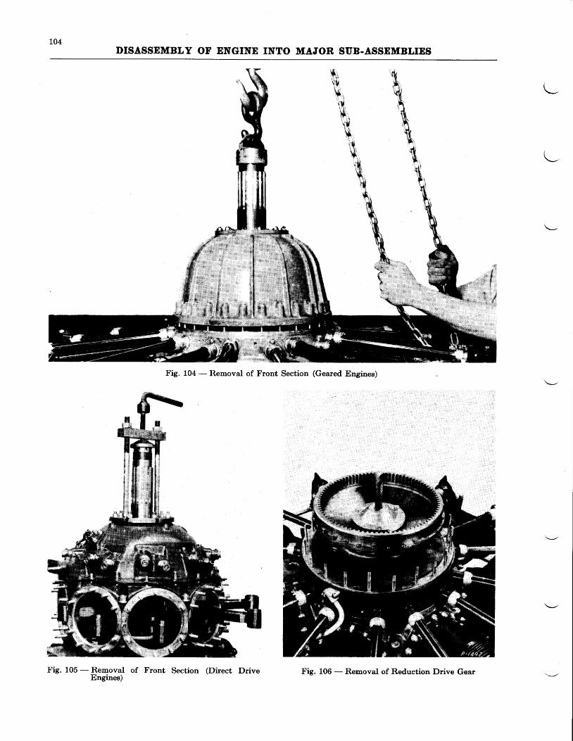
Fig. 107 - flsmsYal of Front
Cautlon-Do not attempt to remove frontsection by hammering on valve tappet guidesor by prying between parting faces of front sec-tion and crankcase.
Front Sectlon (Geared Englnes)-Remove thenuts holding thd front secti-on to the front halfof the main crankcase.
On the Ilornet EG, E2'G, and. E3'G englnes.tt ts lmportant to rernove the short oll feedptpe tn ihe oll supply llne to the governor in6td"t to prevent serious damage to the propelleroil feed bip" assemblyr To remove this- pine,unscrew ilie locator pipe and screw a Vta"-20threaded bolt into the
-internal threads of the
pipe. Pull out the pipe by pulling on the bolt.
Screw the Propeller Shaft Lifting Eye to thefront of the propeller shaft, and, -using a chainhoist, tift the front section from the engine (seeFie. 10a).
Reductlon Drlve Gear-Bend down the tabon the reduction drive gear lock nut, an4 usingthe Lock Nut Wrench, unscrew the lock nut.Usine the Reduction Drive Gear Puller, pull thedrivJgear from the front crankshaft splines (seeFig. 106).
The bearing which supports this geal will-liftout of its support plate when t-he gear -i9 pulled.For removalblthe bearing, see Chapter II.
Half of Main Crankcase
Bearlng Support Plate-Loosen, bu-t - do notremovelhe nut securing the governor drive gearto the front of cam reduction gear. Remove thethree screws holding the bearing support plateto the front half of-the main crankcase and liftoff the plate.
Cam Spacer and Cam (Wasp J".) - Pgfore re-moval examine crankshaft for burrs which mighthinder removal of cam spacer and cam drive gear.These may be removed by stoning. Lift off camspacer and cam.
Cam Reductlon Gear-Lift the cam reductiongear from its bushing in the front crankcase onWasps and Hornets.
- Lift off the spacer and wire
to the cam reduction gear, to assure correct rela-tionship of parts at reassembly. The cam reduc-tion gear on Wasp Jr. engines is removed afterdisasiembly of the main crankcase. For instruc-tions for removal of this part, refer to Chapter II.
Maln Crankcase Sectlon (Front Half)-Un-screw the nine castellated nuts from the throughbolts uniting the two halves of the main crank-case.
Using a fiber drift, tap the nine crankcase boltsdownward until they bottom on the blower sec-tion.
Cautlon-Do not drive bolts against blowersection.
106DISASSDMBLY OF ENGINE INTO MAJOR SUB-ASSEMBLIES
" " ' . . ' ' . :
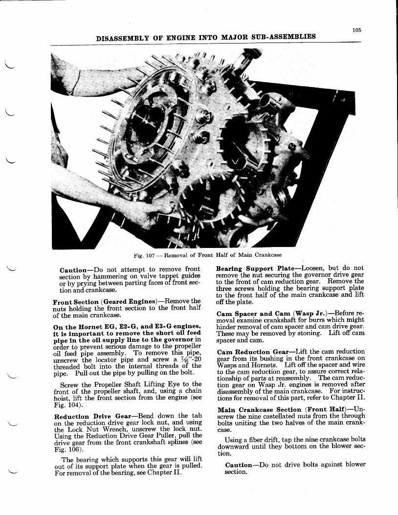
Fig. 108 - Removal of Front Main Bearing Inner Race
Remove the front half of the main crankcase,lifting up evenly on both sides to prevent cramp-ing the front main bearing (see Fig. 107). Itmay be necessary to tap the crankcase lighttywith a fiber drift to start it. The front mainbearing outer race and rollers are removed withthe front half of the crankcase on geared engines.
Subsequent to disassembly of the front halfof the main crankcase on direct drive engines,the front main bearing outer race and rollersshould be lifted from the crankshaft by hand.Early Wasp Jr. B engines were equipped withone-piece front main bearings. See next para-graph for disassembly.
Front Maln Bearlng Inner Race-Before dis-assembling the crankshaft from the engine it isrecommended that the front main bearing innerrace or the one-piece front main bearing on earlyWasp Jr. B engines be removed with the FrontMain Bearing Puller (see Fig. 108).
Crankshaft and Artlculatlng Rod Assern-bly-Screw a Lifting Eye on the forward endof the crankshaft, and lift the complete assemblyfrom the rear half of the main crankcase, bymeans of a chain hoist, and lower upon a suitablecarrier (see Fig. 109).
Maln Crankcase Seetlon (Rear Half)-Un-screw the nuts which fasten this section to the
Fig. 109 - Removal of Crankshaft and Articulating RodAssembly
blower section. Remove this section by liftingit upwards from two positions. One positionshould be at a point between the cylinder pads ofNos. 5 and 6 cylinders, while the other should bedirectly opposite this position. It may be neces-sary to tap the section with a hammer and fiberdrift at several positions in order to release itfrom the blower. Remove the crankcase throughbolts.
Turn the accessory section with the stand sothat the rear section lies in the flight position.Then disassemble the following parts from therear section.
Starter Jaw and Shaft-LInscrew the nut whichfastens the starter jaw to the rear end of thestarter shaft and remove jaw.
Remove the starter drive gear and shaft fromthe accessory section by tapping the shaft for-ward with a fiber drift and hammer.
Generator Drlve Assernbly-Unfasten the fournuts which fasten the generator drive cover andgenerator drive assembly to the rear section andremove these parts.
Magneto Drlve Shafts-Remove screw whichfastens each magneto coupling flange to its re-spective magneto drive shaft and pull each flangefrom its shaft.
LO7DISASSEMBLY OF ENGINE INTO MAJOR SUB-ASSEMBLIES
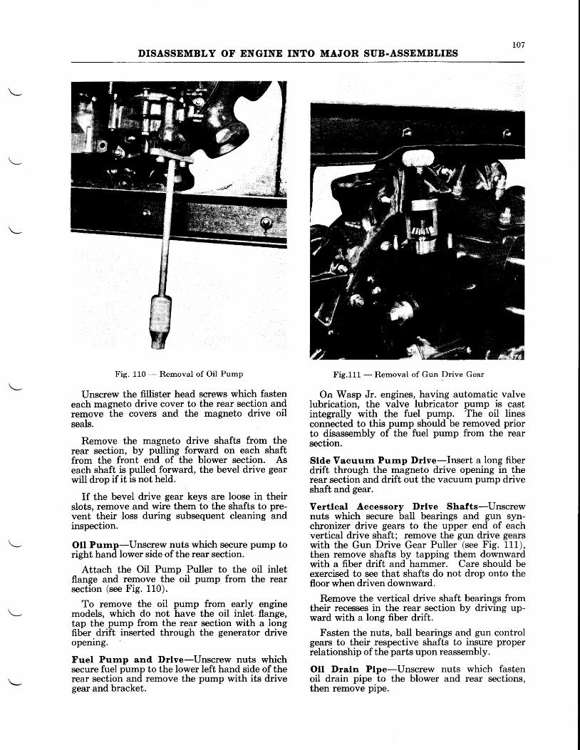
Fig. 110 - Removal of Oil Pump
IJnscrew the fillister head screws which fasteneach magneto drive cover to the rear section andremove the covers and the magneto drive oilseals.
Remove the magneto drive shafts from therear section, by pulling forward on each shaftfrom the front end of the blower section. Aseach shaft is pulled forward, the bevel drive gearwill drop if it is not held.
If the bevel drive gear keys are loose in theirslots, remove and wire them to the shafts to pre-vent their loss during subsequent cleaning andinspection.
Otl Purnp-Unscrew nuts which secure pump toright hand lower side of the rear section.
Attach the Oil Pump Puller to the oil inletflange and remove the oil pump from the rearsection (see Fig. 110).
To remove the oil pump from early enginemodels, which do not have the oil inlet flange,tap the pump from the rear section with a longfiber drift inserted through the generator driveopening.
Fuel Purnp and Drlve-Unscrew nuts whichsecure fuel pump to the lower left hand side of therear section and remove the pump with its drivegear and bracket.
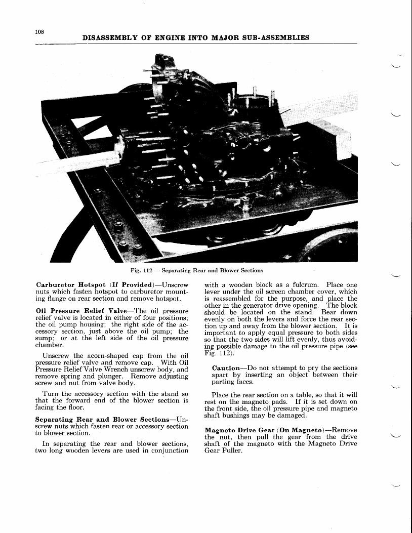
Fig.111 - Removal of Gun Drive Gear
On Wasp Jr. engines, having automatic valveIubrication, the valve lubricator pump is castintegrally with the fuel pump. The oil linesconnected to this pump should be removed priorto disassembly of the fuel pump from the rearsection.
Stde Vacuurn Purnp Drlve-Insert a long fiberdrift through the magneto drive opening in therear section and drift out the vacuum pump driveshaft and gear.
Vertlcal Aeeessory I)rlve Shafts-IJnscrewnuts which secure ball bearings and gun syn-chronizer drive gears to the upper end of eachvertical drive shaft; remove the gun drive gearswith the Gun Drive Gear Puller (see Fig. 111),then remove shafts by tapping them downwardwith a fiber drift and hammer. Care should beexercised to see that shafts do not drop onto thefloor when driven downward.
Remove the vertical drive shaft bearings fromtheir recesses in the rear section by driving up-ward with a long fiber drift.
Fasten the nuts, ball bearings and gun controlgears to their respective shafts to insure properrelationship of the parts upon reassembly.
Otl Draln Ptpe-Unscrew nuts which fastenoil drain pipe to the blower and rear sections,then remove pipe.
108DISASSEMBLY OF ENGINE INTO MAJOR SUB.ASSEMBLIES
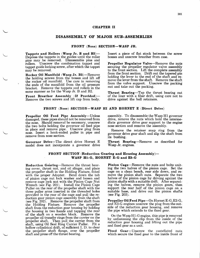
Fig. 112 *- Separating Rear and Blower Sections
Carburetor Hotspot 1If Provided)-Unscrewnuts which fasten hotspot to carburetor mount-ing flange on rear section and remove hotspot.
Otl Pressure Relief Valve-The oil pressurerelief valve is located in either of four positions;the oil pump housing; the right side of the ac-cessory section, just above the oil pump; thesump; or at the left side of the oil pressurechamber.
Unscrew the acorn-shaped cap from the oilpressure relief valve and remove cap. With OilPressure Relief Valve Wrench unscrew body, andremove spring and plunger. Remove adjustingscrew and nut from valve body.
Turn the accessory section with the stand sothat the forward end of the blower section isfacing the ffoor.
Separating Rear and Blower Sectlons-Un-screw nuts which fasten rear or accessory sectionto blower section
In separating the rear and blower sections,two long wooden levers are used in conjunction
with a wooden block as a fulcrum. Place onelever under the oil screen chamber cover. whichis reassembled for the purpose, and place theother in the generator drive opening. The blockshould be located on the stand. Bear downevenly on both the levers and force the rear sec-tion up and away from the blower section. It isimportant to apply equal pressure to both sidesso that the two sides will lift evenly, thus avoid-ing possible damage to the oil pressure pipe (seeFie. 112) .
Caution-Do not attempt to pry the sectionsapart by inserting an object between theirparting faces.
Place the rear section on a table, so that it willrest on the magneto pads. If it is set down onthe front side, the oil pressure pipe and magnetoshaft bushings may be damaged.
Magneto I)rlve Gear (On Magneto)-Removethe nut, then pull the gear from the driveshaft of the magneto with the Magneto DriveGear Puller.

109DISASSEMBLY OF ENGINE INTO MAJOR SUB-ASSEMBLIES
TOOL LIST
Tool Name
DDPRESSOR - Rocker Arm. .
Tool No.
PWA-455
EYD - L i f t ing, #30 Spl ine. . . . . . . .PWA-520
EYE - L i f t ing, #40 Spl ine. . . . . . . .PWA-1332
EYE - L i f t ing, #50 Spl ine. . . . . . . .PWA-1333
EYE - Lifting, For Geared Crankshafts.PWA-662
EYE - Lifting, For Geared Crankshafts.PWA-1079
PLATE - Mounting, IJse with TAM-1161 . . TC-23007
PULLER - Front Main Bearing (One PieceBearing) . PWA-150
PULLER
PULLER
PULLER
PULLER
PULLER
PULLER
PULLER
PULLDR
PULLER
PULLER
STANI)
WRDNCE
WRDNCE
WRENCE
WRDNCE
WRENCE
WRDNCE
WRENCE
WRDNCE
WRENCE
WRENCE
WRDNCE
WRDNCH
WRDNCE
WRENCE
WRENCE
WRENCE
WRENCE
WRENCE
WRENCE
WRENCE
WRDNCE
WRDNCE
WRENCE
. . . . P W A - 4 7 0
. . . . P W A - 5 0 5
. . . .PWA-L6L7
. . . . P W A - 6 7
. . . .PWA-657
. . . .PWA-2372
. . . . P W A - 6 2 1
. . . .PWA-L327
. . . . P W A - 4 4 2
. . . . P W A - 3 9 4TC.. . . . T A M - I 1 6 1
- Front Main Bearing- Front Main Bearing- Front Main Bearing- Front Section- Front Section- Gun Drive Gear- Magneto Drive Gear. . . : . .- Oil Pump- Reduction Drive Gear. . . . .- Reduction Drive Gear. . . . .- Engine Overhaul, Use with
23007
-Crankshaft, #SOSpline . . . .PWA-112- Crankshaft, #40Spline . . . .PWA-155- Crankshaft, #50 Spline. . . .PWA-197- Cylinder Nut . . PWA-186- Intake Pipe Packing Nut . PWA-237- Intake Pipe Packing Nut . .PWA-144- Oil Pressure Relief Valve. . PWA-67L-O i lSc reen Cove r . . . .PWA-228- Oil Sump Nut. . PWA-341- Push Rod Tube Gland . . . .PWA-2434- Reduction Drive Gear Lock Nut. PWA-504- Reduction Drive Gear Lock Nut. PWA-660-Thrust Nut . . . .PWA-1093-Th rus t Nu t . . . .PWA-1092- Thrust Nut. . . PWA-1084-Th rus t Nu t . . . .PWA-1094- Thrust Nut. . . .PWA-1095- SPark Plug - rY*" hex. . . . PWA-1398- BendixPlugTB - 74" hex.. . . . . .PWA-L44I- Bendix Plug656 - Y4" hex.. . . . .PWA-1474- Bendix LS10 - V8" hex.. . PWA-1684- Aero LS 1AB - 34" hex.. PWA-1696- Aero LS 3AB - ,(" hex., BG LS
32L - 78" hex., and AN typeplugs - 78" hex. . . . .PWA-2254
Wasp Jr. Wasp Hornet
B 82 B3 E1 ET. G D E.G E2.G 88. G
x x x x x x x x I
x x xx x x
x x xx
x x xx x x x x x x x x
x
x x x x xx
x x xx x x
x xx x x x x x x x xx x x x x x x x xx x x x x x x x x
xx x x
x x x x x x x x x
x x xx x x
x x xx x x x x x x x xx x x
x x x x x xx x x x x x x x xx x x x t x x x xx x x x x x x x I
x x x x x x x x rx
x x xx x x
xx x
x xx
x x x x x x x x xx x x x x x x x xx x x x x x x x xx x x x x x x x xx x x x x x x x x
x x x x x x x x x
20r
CHAPTER II
DISASSEMBLY OF MAJOR SUB.ASSEMBLIES
FRONT (Nose) SECTION-WASP JR.
Tappets and Rollers (Wasp Jr. B and B2)-Depress the tappets in the guides until the rollerpin-s may be removed. Disassemble pins andiollers. Unscrew the combination tappet andtappet guide loc\ing screw, after which the tappetmay be removed.
Rocker Otl Mantfold (Wasp Jr. B3)-Removethe holding screws from the bosses and lift offthe rocker oil manifold. Use care in removingthe ends of the manifold from the oil pressurebracket. Remove the tappets and rollers in thesame manner as for the Wasp Jr. B and 82.
Front Breather Assernbly (If Provlded)-Remove the two screws and lift cap from body.
FRONT (Nose) SECTION-WASP HI
Propeller Otl Feed Ptpe Assernbly-Unlessdamaged, these pipes should not be removed fromthe nose. Should removal be necessary, unscrewthe two bolts holding the governor oil feed pipein place and remove pip_e., Unscrew plug fromnos-e. Insert a hook-ended puller in pipe andremove from nose section.
Governor Drtve-The direct drive Hornet Emodel does not incorporate a governor drive
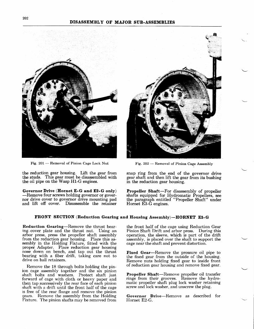
Reductlon Gebring-Remove the thrust bear-ing cover, thrust nut, and oil slinger, and placethe propeller shaft in the Holding Fixture, fittedwith the proper Adapter. Bend down the tabof pinion cage nut lock washer and loosen andremove cage lock nut with the Pinion Cage NutWrench (see Fig. 201). Install the Pinion CagePuller on the rear of the propeller shaft with thethree puller arms inserted in the threaded holesprovided in the rear of the cage and pull the re-duction gear pinion cage assembly from the shaft(see Fig. 202). Remove the propeller shaft fromthe Holding Fixture. Remove the propellershaft from the reduction gear housing by holdingthe housing in two hands and tapping the rearof the shaft on a wooden block. Remove thepropeller oil transfer rings from the carrier on thebrobeiler shaft. Then pull the carrier from theshait, using Oil Seal Ring Carrier Puller. Fit ahollow cylindrical drift, of sufficient I. D. to clearthe propeller shaft flange, over the propellershaft and press off the thrust bearing.
Insert a piece of flat stock between the screwbosses and unscrew breather from case.
Propeller Regulator Valve-Remove the nutssecuring the propeller regulator valve assemblyto the front section. Lift the complete assemblyfrom the front section. Drift out the tapered pinholding the lever to the end of the shaft and re-move the lever from the shaft. Remove the shaftfrom the valve support. IJnscrew the packingnut and take out the packing.
Thrust Bearlng-Tap the thrust bearing outof the liner with a fiber drift, using care not todrive against the ball retainers.
AND HORNET E (Dlrect Drlve)
assembly. To disassemble the Wasp H1 governordrive, remove the nuts which hold the interme-diate governor drive gear support to the enginenose section and remove the assembly.
Remove the retainer snap ring from thegovernor drive gear shaft and slip the shaft fromits bushing.Thrust Bearlng-Remove as described forWasp Jr. engines.
Plnlon Cage-Remove the nuts and bolts unit-ing the two halves of the pinion cage. Set thecage on a clean bench, rear side down, and re-move the pinion shaft nuts. Separate the twohalves of the pinion cage by driving against thepinion shafts with a suitable drift. After separat-ing the halves, remove the pinion gears, thensupport the rear half of the pinion cage on asuitable base, and drive out the pinion shafts(see Fig. 203).
Propeller Oll Feed Ptpe-On Hornet E-G, E2-G,and E3-G engines unscrew the plug from the out-side of the reduction gear housing, and removethe pipe which extends to the fixed gear.
On the Wasp H1-G engine, this pipe is removedby unfastening the clip from the inside of thereduction gear housing and lifting out the pipeand fixed gear as a unit.
Flxed Gear-Unscrew the castellated nutswhich secure the fixed gear to the inside front of
FRONT SECTION (Reductlon Gearlng and Ilouslng Assernbly)-WASP Hl-G, HORNET E-G and Ez-G
202DISASSEMBLY OF MAJOR SUB-ASSEMBLIES
tl
Fig. 201 - Removal of Pinion Cage Lock Nut
the reduction gear housing. Lift the gear fromthe studs. This gear must be disassembled withthe oil pipe on the Wasp Hl-G engines.
Governor Drlve (Hornet E-G and Ez-G only)-Remove four screws holding governor or gover-nor drive cover to governor drive mounting padand tift off cover. Disassemble the retainer
FRONT SECTION (Reductlon Gearlng
Reduction Gearing-Remove the thrust bear-ing. cover plate and the thrust nut. Using anarbor press, press the propeller shaft assemblyfrom the reduction gear housing. Place this as-sembly in the Holding Fixture, fitted with theproper Adapter. Place reduction gear housingnose down on bench, and tap out the thrustbearing with a fiber drift, taking care not todrive on ball retainers.
Remove the 18 through bolts holding the pin-ion cage assembly together and the six pinionshaft bolts and washers. Protect shaft justforward of cage with cloth or heavy paper andthen tap successively the rear face of each pinionshaft with a drift until the front half of the cageis free of the rear flange and remove the piniongears. Remove the assembly from the HoldingFixture. The pinion shafts may be removed from
Fie. 202 - Removal of Pinion Cage Assembly
snap ring from the end of the governor drivegear shaft and then lift the gear from its bushingin the reduction gear housing.
Propeller Shaft-For disassembly of propellershafts equipped for Hydromatic Propellers, seethe paragraph entitled "Propeller Shaft" underHornet E3-G engines.
and Ilouslng Assernbly)-HORNET E8-G
the front half of the cage using Reduction GearPinion Shaft Drift and arbor press. During thisoperation, the sleeve, which is part of the driftassembly, is placed over the shaft to support thecage near the shaft and prevent distortion.
Flxed Gear-Remove the pressure oil pipe tothe fixed gear from the outside of the housing.Remove nuts holding fixed gear to inside frontof reduction gear housing and remove fixed gear.
Propeller Shaft-Remove propeller oil transferrings from their grooves. Remove the hydro-matic propeller shaft plug lock washer retainingscrew and lock washer, and unscrew the plug.
Governor Drive-Remove as described forHornet E2-G.
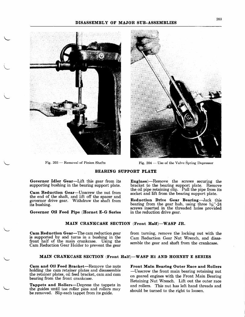
203DISASSEMBLY OF MAJOR SUB.ASSEMBLIES
Fig. 203 - Removal of Pinion Shafts
BEARING SUPPORT PLATE
Governor fdler Gear-Lift this gear from itssupporting bushing in the bearing support plate.
Carn Reductlon Gear-Unscrew the nut fromthe end of the shaft, and lift off the spacer andgovernor drive gear. Withdraw the shaft fromits bushing.
Governor Otl Feed Plpe (Ilornet E-G Serles
Englnes)-Remove the screws securing thebracket to the bearing support plate. Removethe oil pipe retaining clip. Pull the pipe from itssocket and lift from the bearing support plate.
Reductlon l)rlve Gear Bearlng-Jack thisbearing from the gear hub, using three 5 "-24screws inserted in the threaded holes providedin the reduction drive gear.
MAIN CRANKCASE SECTION (Front Half)-WASP JR.
Carr Reductlon Gear-The cam reduction gearis supported by and turns in a bushing in thefront half of the main crankcase. Using theCam Reduction Gear Holder to prevent the gear
Carn and Oll Feed Bracket-Remove the nutsholding the cam retainer plates and disassemblethe retainer plates, oil feed bracket, cam and cambearing from the front crankcase.
Tappets and Rollers-Depress the tappets inthe guides until tne roller pins and rollers maybe removed. Slip each tappet from its guide.
from turning, remove the locking nut with theCam Reduction Gear Nut Wrench, and disas-semble the gear and shaft from the crankcase.
Front Maln Bearlng Outer Race and Rollers-LJnscrew the front main bearing retaining nuton geared engines with the Front Main BearingRetaining Nut Wrench. Lift out the outer raceand rollers. This nut has left hand threads andshould be turned to the right to loosen.
MAIN CRANKCASE SECTION (Front IIalf)-WASP IIr AND HORNET E SERIES
Fig. 204 - IJse of the Valve Spring Depressor
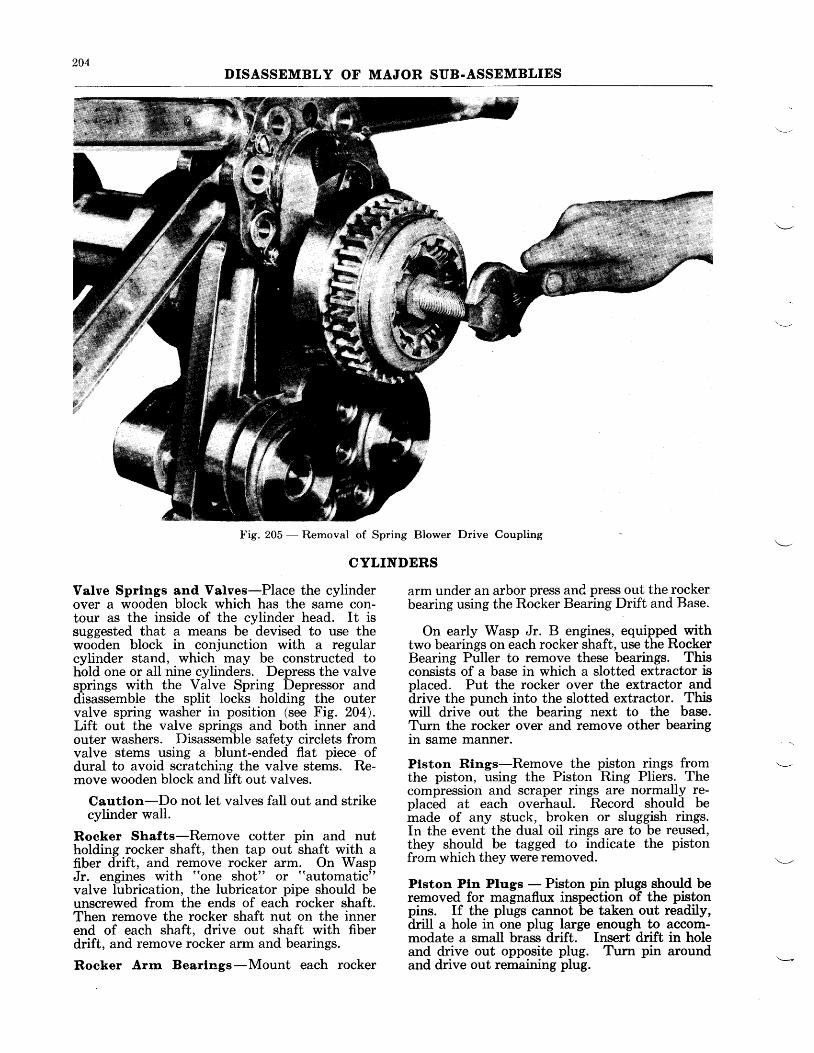
204DISASSEMBLY OF MAJOR SUB.ASSEMBLIES
Fig. 205 - Removal of Spring Blower Drive Coupling
CYLINDERS
Valve Sprlngs and Valves-Place the cylinderover a wooden block which has the same con-tour as the inside of the cylinder head. It issuggested that a means be devised to use thewooden block in conjunction with a regularcylinder stand, which may be constructed tohold one or all nine cylinders. Depress the valvesprings with the Valve Spring Depressor anddisassemble the split locks holding the outervalve spring washer in position (see Fig. 204).Lift out the valve springs and both inner andouter washers. Disassemble safety circlets fromvalve stems using a blunt-ended flat piece ofdural to avoid scratching the valve stems. Re-move wooden block and lift out valves.
Cautlon-Do not let valves fall out and strikecylinder wall.
Rocker Shafts-Remove cotter pin and nutholding rocker shaft, then tap out shaft with afiber drift, and remove rocker arm. On WaspJr. engines with "one shot" or "automatic"
valve lubrication, the lubricator pipe should beunscrewed from the ends of each rocker shaft.Then remove the rocker shaft nut on the innerend of each shaft, drive out shaft with fiberdrift, and remove rocker arm and bearings.
Rocker Arm Bearings-Mount each rocker
arm under an arbor press anC press out the rockerbearing using the Rocker Bearing Drift and Base.
On early Wasp Jr. B engines, equipped withtwo bearings on each rocker shaft, use the RockerBearing Puller to remove these bearings. Thisconsists of a base in which a slotted extractor isplaced. Put the rocker over the extractor anddrive the punch into the slotted extractor. Thiswill drive out the bearing next to the base.Turn the rocker over and remove other bearingin same manner.
Plston Rlngs-Remove the piston rings fromthe piston, using the Piston Ring Pliers. Thecompression and scraper rings are normally re-placed at each overhaul. Record should bemade of any stuck, broken or sluggish rings.In the event the dual oil rings are to be reused,they should be tagged to indicate the pistonfrcm which they were removed.
Plston Ptn Plugs - Piston pin plugs should beremoved for magnaflux inspection of the pistonpins. If the plugs cannot be taken out readily,drill a hole in one plug large enough to accom-modate a small brass drift. Insert drift in holeand drive out opposite plug. Turn pin aroundand drive out remaining plug.
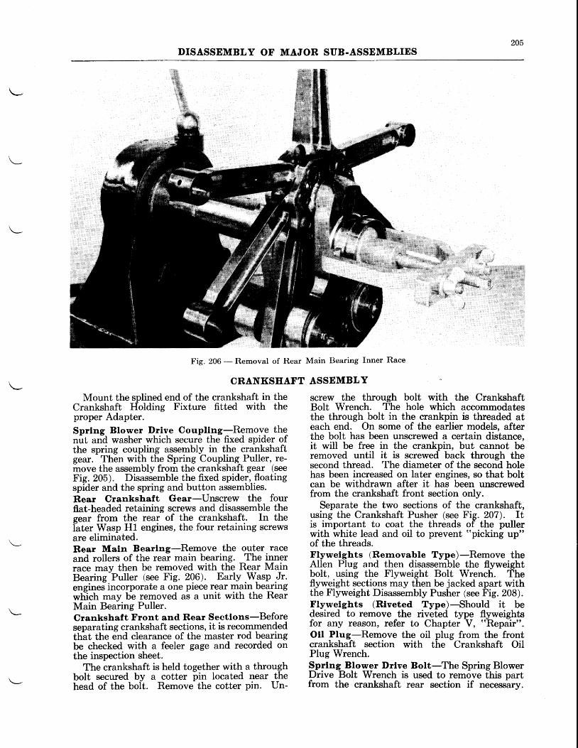
205DISASSEMBLY OF MAJOR SUB.ASSEMBLIES
N.a
Fig. 206 -- Removal of Rear Main Bearing Inner Race
CRANKSHAFT ASSEMBLY
Mount the splined end of the crankshaft inCrankshaft Holding Fixture fitted withproper Adapter.Sprlng Blower Drive Coupllng-Remov_e thenut and washer which secure the fixed spider ofthe spring coupling assembly in the crankshaftgear.
- Then with the Spring Coupling Puller, re-
move the assembly from the crankshaft gear (seeFig. 205). Disassemble the fixed spider,,floatingspider and the spring and button assemblies.Rear Crankshaft Gear-Unscrew the fourflat-headed retaining screws and disassemble thegear from the rear of the crankshaft. In thel-ater Wasp H1 engines, the four retaining screwsare eliminated.Rear Maln Bearlng-Remove the outer raceand rollers of the rear main bearing. The innerrace may then be removed with the Rear MainBearing-Puller (see Fig. 296). Early.Wgsp .Jr.engrnes rncorporate a one piece rear main bearingwtich may b-e removed as a unit with the RearMain Bearing Puller.Crankshaft Front and Rear Sectlons-Beforeseparating crankshaft sections, it is recommendedth-at the end clearance of the master rod bearingbe checked with a feeler gage and recorded onthe inspection sheet.
The crankshaft is held together with a throughbolt secured by a cotter pin located near thehead of the bolt. Removs the cotter pin. Un-
screw the through bolt with the CrankshaftBolt Wrench. The hole which accommodatesthe through bolt in the crankpin is threaded ateach end. On some of the earlier models, afterthe bolt has been unscrewed a certain distance,it will be free in the crankpin, but cannot beremoved until it is screwed back through thesecond thread. The diameter of the second holehas been increased on later engines, so that boltcan be withdrawn after it has been unscrewedfrom the crankshaft front section only.
Separate the two sections of the crankshaft,using the Crankshaft Pusher (see Fig. 207). Itis important to coat the threads of the pullerwith white lead and oil to prevent "picking up"of the threads.Flywelghts (Rernovable Typ")-Remove theAllen PIug and then disassemble the flyweightbolt, using the Flyweight Bolt Wrench. Theflyweight sections may then be jacked apart withthe Flyweight Disassembly Pusher (see Fig. 208).Flywelghts (Rtveted Type)-Should it bedesired to remove the riveted type flyweightsfor any reason, refer to Chapter V, "Repair".
Otl Plug-Remove the oil plug from the frontcrankshaft section with the Crankshaft OitPlug Wrench.
thethe
Sprlng Blower Drive Bolt-The Spring BlowerDrive Bolt Wrench is used to remove this partfrom the crankshaft rear section if necessarv.
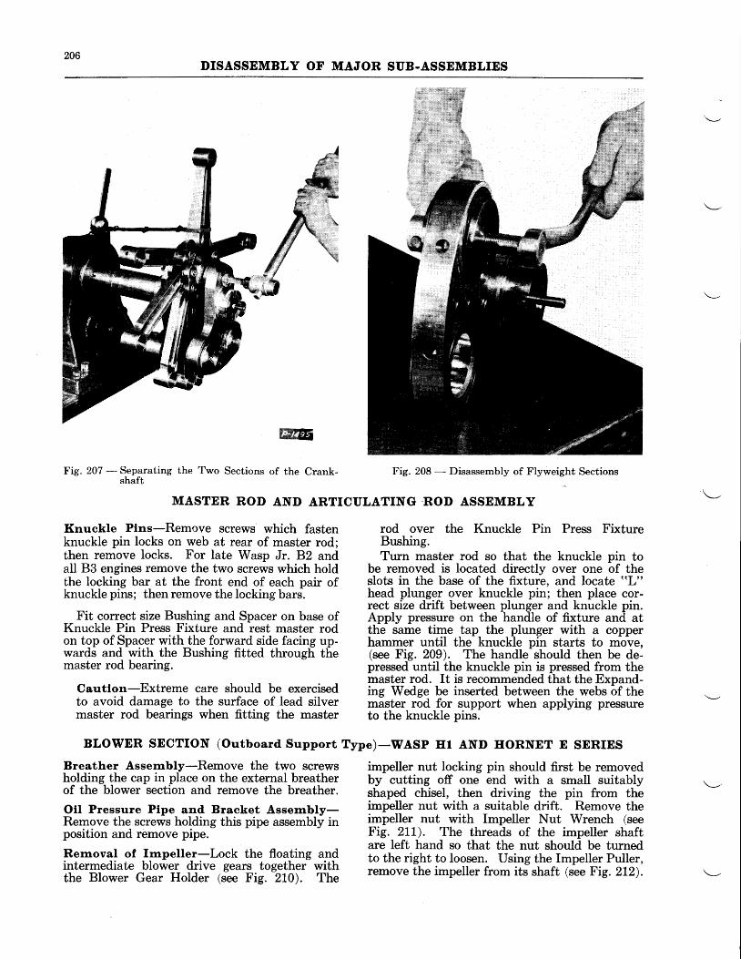
206DISASSEMBLY OF MAJOR SUB-ASSEMBLIES
W
Fig- 207 - Separating the Two Sections of the Crank-shaft
Knuckle Plns-Remove screws which fastenknuckle pin locks on web at rear of master rod;then remove locks. For late Wasp Jr. B2 andall 83 engines remove the two screws which holdthe locking bar at the front end of each pair ofknuckle pins; then remove the locking bars.
Fit correct size Bushing and Spacer on base ofKnuckle Pin Press Fixture and rest master rodon top of Spacer with the forward side facing up-wards and with the Bushing fitted through themaster rod bearing.
Cautlon-Extreme care should be exercisedto avoid damage to the surface of lead silvermaster rod bearings when fitting the master
Breather Assernbly-Remove the two screwsholding the cap in place on the external breatherof the blower section and remove the breather.
Oll Pressure Ptpe and Bracket Asserrbly-Remove the screws holding this pipe assembly inposition and remove pipe.
Rernoval of knpeller-Lock the floating andintermediate blower drive gears together withthe Blower Gear Holder (see Fig. 2L0). The
MASTER ROD AND ARTICULATING .ROD ASSEMBLY
Fig. 208 - Disassembly of Flyweight Sections
rod over the Knuckle Pin Press FixtureBushing.Turn master rod so that the knuckle pin to
be removed is located directly over one of theslots in the base of the fixture, and locate "L"
head plunger over knuckle pin; then place cor-rect size drift between plunger and knuckle pin.Appty pressure on the handle of fixture and atthe same time tap the plunger with a copperhammer until the knuckle pin starts to move,(see Fig. 209). The handle should then be de-pressed until the knuckle pin is pressed from themaster rod. It is recommended that the Expand-ing Wedge be inserted between the webs of themaster rod for support when applying pressureto the knuckle pins.
impeller nut locking pin should first be removedby cutting off one end with a small suitablyshaped chisel, then driving the pin from theimpeller nut with a suitable drift. Remove theimpeller nut with Impeller Nut Wrench (seeFig. zLL). The threads of the impeller shaftare left hand so that the nut should be turnedto the right to loosen. Using the Impeller Puller,remove the impeller from its shaft (see Fig. 2L2).
BLOWER SECTION (Outboard Support Type)-WASP Hr AND IIORNET E SERIES
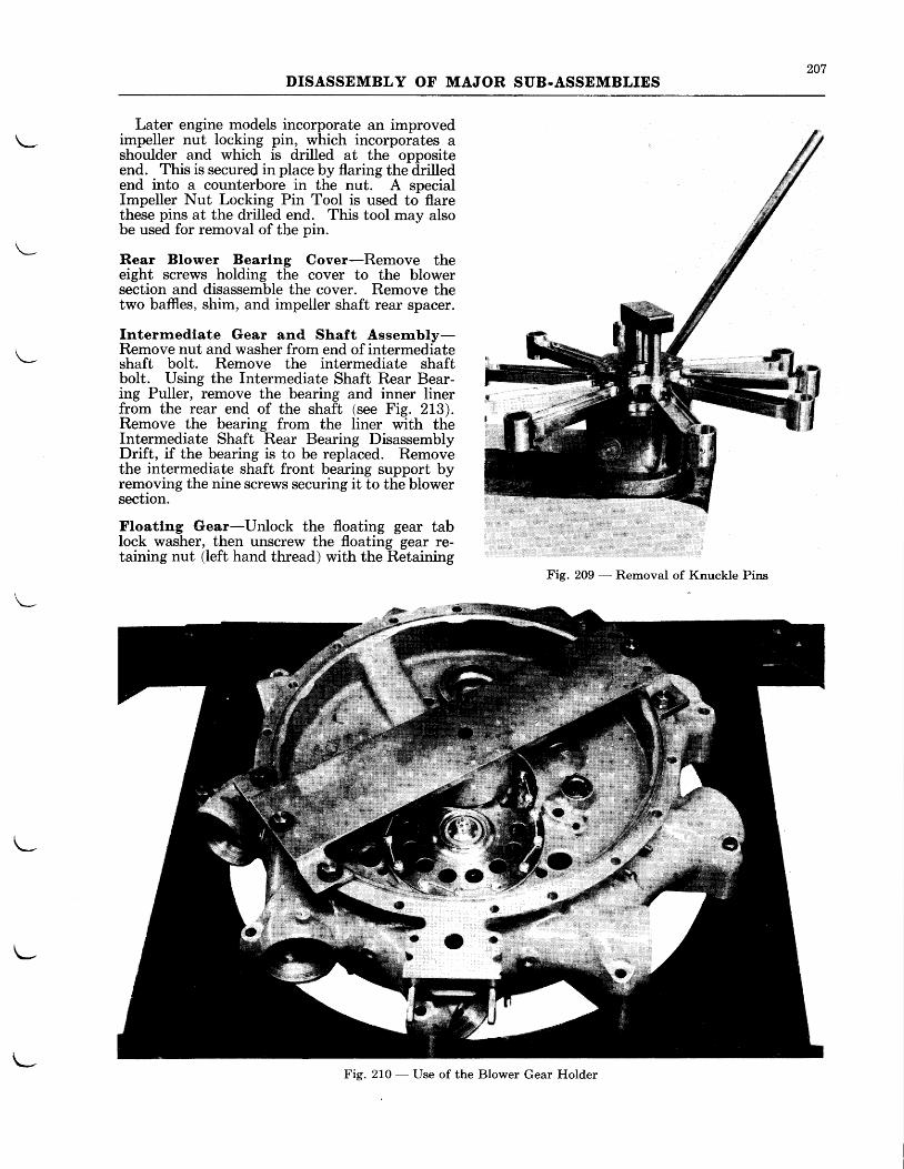
207DISASSEMBLY OF MAJOR SUB.ASSEMBLIES
Later engine models incorporate an improvedimpeller nut locking pin, which incorporates ashoulder and which is drilled at the oppositeend. This is secured in place by flaring the drilledend into a counterbore in the nut. A specialImpeller Nut Locking Pin Tool is used to flarethese pins at the drilled end. This tool may alsobe used for removal of the pin.
Rear Blower Bearing Cover-Remove theeight screws holding the cover to the blowersection and disassemble the cover. Remove thetwo baffies, shim, and impeller shaft rear spacer.
Intermediate Gear and Shaft Assernbly-Remove nut and washer from end of intermediateshaft bolt. Remove the intermediate shaftbolt. Using the Intermediate Shaft Rear Bear-ing Puller, remove the bearing and inner linerfrom the rear end of the shaft (see Fig. 2L3).Remove the bearing from the liner with theIntermediate Shaft Rear Bearing DisassemblyDrift, if the bearing is to be replaced. Removethe intermediate shaft front bearing support byremoving the nine screws securing it to the blowersectron.
Floating Gear-Unlock the floating gear tablock washer, then unscrew the floating gear re-taining nut (left hand thread) with the Retaining
Fig. 209 - Removal of Knuckle Pins
U
Fig. 210 - Use of the Blower Gear HolderL-
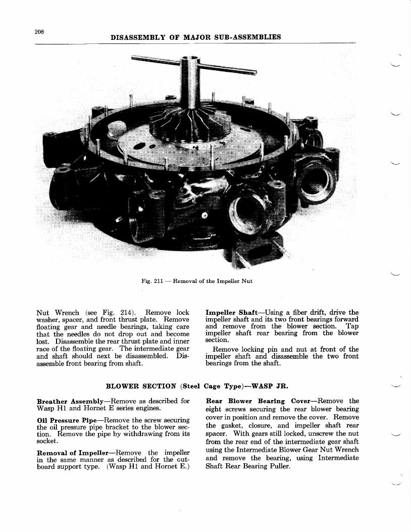
208DISASSEMBLY OF MAJOR SUB-ASSEMBLIES
Fig. 211 - Removal of the Impeller Nut
Nut Wrench (see Fig. 2L4). Remove lockwasher, spacer, and front thrust plate. Removefloating gear and needle bearings, taking carethat the needles do not drop out and becomelost. Disassemble the rear thrust plate and innerrace of the floating gear. The intermediate gearand shaft should next be disassembled. Dis-assemble front bearing from shaft.
BLOWER SECTION (Steel
Breather Assernbly-Remove as described forWasp H1 and Hornet E series engines.
Oll Pressure Ptpe-Remove the screw securingthe oil pressure pipe bracket to the blower sec-tion. Remove the pipe by withdrawing from itssocket.
Rernoval of Irnpeller-Remove the impellerin the same manner as described for the out-board support type. (Wasp H1 and Hornet E.)
hnpeller Shaft-Using a fiber drift, drive theimpeller shaft and its two front bearings forwardand remove from the blower section. Tapimpeller shaft rear bearing from the blowersection.
Remove locking pin and nut at front of theimpeller shaft and disassemble the two frontbearings from the shaft.
Cage Type)-WASP JR.
Rear Blower Bearlng Cover-Remove theeight screws securing the rear blower bearingcover in position and remove the cover. Removethe gasket, closure, and impeller shaft rearspacer. With gears still locked, unscrew the nutfrom the rear end of the intermediate gear shaftusing the Intermediate Blower Gear Nut Wrenchand remove the bearing, using IntermediateShaft Rear Bearing Puller.
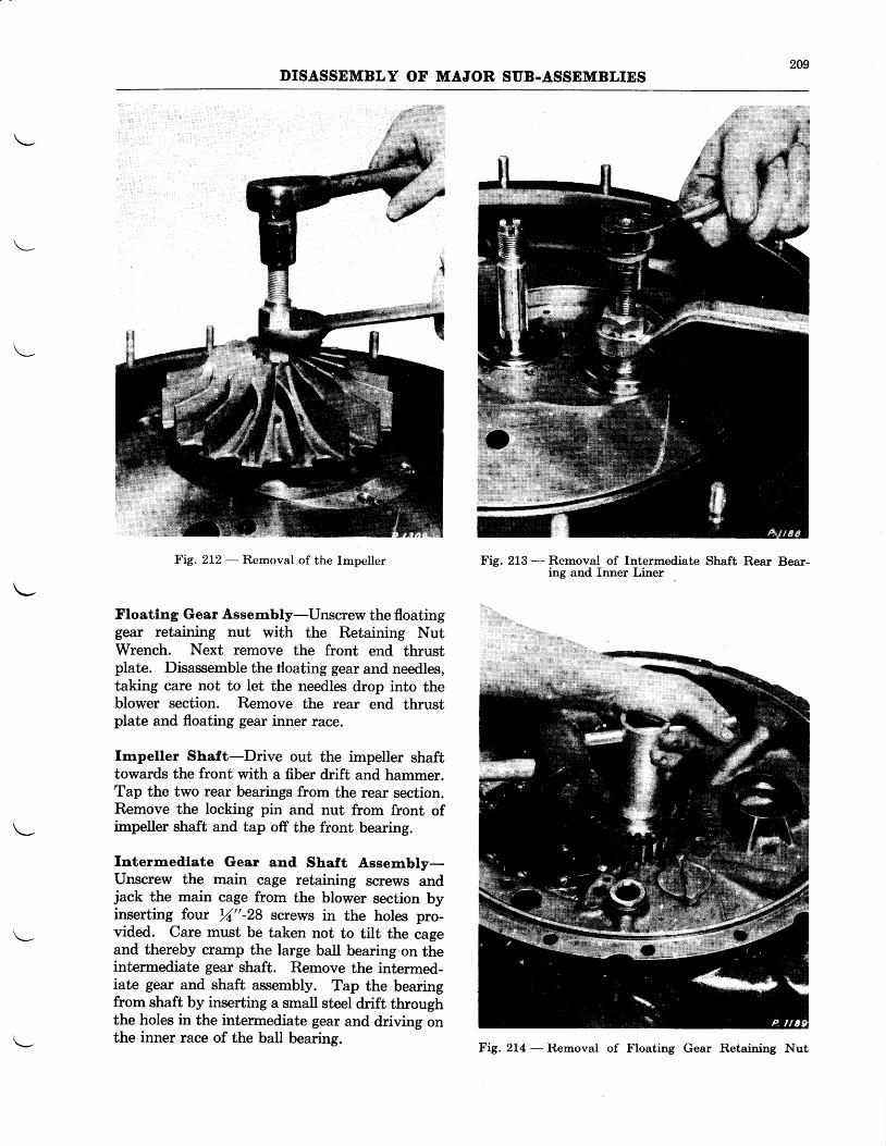
209DISASSEMBLY OF MAJOR SUB.ASSEMBLIES
Fig. 212 - Removal of the Impeller
Floatlng Gear Assernbly-Unscrew the floatinggear retaining nut with the Retaining NutWrench. Next remove the front end thrustplate. Disassemble the tloating gear and needles,taking care not to let the needles drop into theblower section. Remove the rear end thrustplate and floating gear inner race.
Impeller Shaft-Drive out the impeller shafttowards the front with a fiber drift and hammer.Tap the two rear bearings from the rear section.Remove the locking pin and nut from front ofimpeller shaft and tap off the front bearing.
Interm.edlate Gear and Shaft Assernbly-llnscrew the main cage retaining screws andjack the main cage from the blower section byinserting four rZ"-28 screws in the holes pro-vided. Care must be taken not to tilt the cageand thereby cramp the large ball bearing on theintermediate gear shaft. Remove the intermed-iate gear and shaft assembly. Tap the bearingfrom shaft by inserting a small steel drift throughthe holes in the intermediate gear and driving onthe inner race of the ball bearing.
Fig. 213 - Removal of Intermediate Shaft Rear Bear-ing and Inner Liner
Fig. 2L4 - Removal of Floating Gear Retaining Nut
2L0DISASSEMBLY OF MAJOR SUB.ASSEMBLIES
REAR
Generator Drive Assembly-For the singlebearing type remove four screws holding thebearing retainer plate in place and remove thedrive gear assembly from bracket. Fasten thegear assembly in a soft jawed vise, remove theiotter pin, and using Generator Drive Gear NutWrench, unscrew the spanner nut holding thebearing on shaft. Remove the bearing by tap-ping with a fiber drift.
For the double bearing type fasten the assem-bly in a soft jawed vise. Bend down the tab ofthe lock washer and remove the spanner nut fromthe end of the shaft, using Generator Drive GearNut Wrench. Tap the gear from the innerraces of the bearings and remove the outerbearing and spacer. LJnscrew the four screwsholding the bearing retainer plate in place andremove the plate and inner bearing.
Otl Purnp-There are four through bolts thatsecure the various sections of the oil pump to-gether. Two of these bolts are a loose fit whilefhe other two are a tight fit and act as dowelsto keep the various sections in alignment.
Remove the nuts and washers from the twotight bolts and drift them from the pump. Thenremove the nuts from the two loose bolts andremove the bolts. Detach the base, or pressure
SECTION
section, of the pump from the scavenge sections.If difficulty is experienced in removing the gearwhich is keyed to the drive shaft, place it in asoft jawed vise and remove it by tapping lightlyon the end of the drive shaft. At the same timehold the pump sections away from the gear toprevent the key from imbedding in the adjacentsection.
Remove the remaining sections and gears inthe same manner until the disassembly is com-plete.
Valve Lubrlcator Pump (If Provtded)-Un-screw the four nuts holding the cover plate inposition and lift off the cover plate. Withdrawthe shaft and spring assembly, and remove thetwo ball thrust bearings. Using a brass drift,remove the drive gear shaft and tift out thedrive gear.
Stde Vaeuurn Purnp Drlve-Drive out thecotter pin and remove the nut from the end ofthe drive shaft. Disassemble the two ball bear-ings and spacer from the shaft.
Starter Shaft and, Bearlng-Remove thebearing from the shaft with the Starter ShaftBearing Puller. Remove the bearing spacerfrom the shaft.
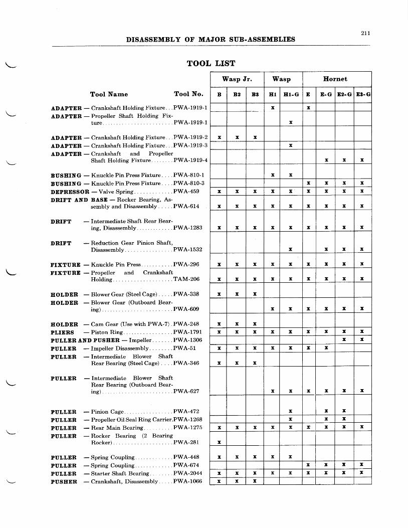
211DISASSEMBLY OF MAJOR SUB.ASSEMBLIES
TOOL LIST
Tool Narne Tool No.
ADAPTER - Crankshaft Holding Fixture. . .PWA-1919-1
ADAPTER - Propeller Shaft Holding Fix-ture. . . PWA-1919-1
ADAPTDR - Crankshaft Holding Fixture. . . PWA-19L9-2
ADAPTER - Crankshaft Holding Fixture. . .PWA-1919-3
ADAPTDR - Crankshaft and PropellerShaft Holding Fixture . . PWA-1919-4
BUSEING - Knuckle Pin Press Fixture. . . . PWA-810-1
BUSEING - Knuckle Pin Press Fixture. . . .PWA-810-3
DEPRESSOR -Valve Spr ing . . .PWA-459
DRIFT AND BASD - Rocker Bearing, As-sembly and Disassembly PWA-614
- Reduction Gear Pinion Shaft,D i sassemb ly . . . . . .PWA-1532
FIXTURE - Knuckle Pin Press PWA-296
FIXTURD - Propeller and CrankshaftHolding . . . .TAM-206
EOLDER - Blower Gear (Steel Cage) PWA-338
EOLDER - Blower Gear (Outboard Bear-i te) . . .PWA-609
EOLDER - Cam Gear (Use with PWA-7) . PWA-248
PLIERS - Piston Ring. PWA-1791,
PULLER AND PUSEER - Impeller. . . . . . .PWA-1306
PULLDR - Impeller Disassembly. . .PWA-51
PULLDR - Intermediate Blower ShaftRearBearing (Steel Cage) . . . .PWA-346
PULLDR - Intermediate Blower ShaftRear Bearing (Outboard Bear-i ng ) . . .PWA-627
DRIFT
DRIFT
PULLER
PULLER
PULLER
PULLDR
- Intermediate Shaft Rear Bear-ing, Disassembly . PWA-1283
- Pinion Cage PWA472- Propeller OiI Seal Ring Carrier.PWA-1268- Rear Main Bearing . . . .PWA-7275- Rocker Bearing (2 Bearing
Rocke r ) . . . .PWA-281
PULLDR -Spr ingCoupl ing . .PWA-448
PULLER -Spr ingCoupl ing . .PWA-674
PULLER - Starter Shaft Bearing . . PWA-2044
PUSEER - Crankshaft, Disassembly. . . . .PWA-1066
Wasp Jr. Wasp Ilornet
B 82 B3 ET ET. G E E . G E2.G 83. G
x x
x
x x xx
x x x
x xx x x x
x x x x x x x x x
x x x x x x x x x
x x x x x x x x x
x x x x
x x x x x x x x x
x x x x x x x x x
x x x
x x x x x x
x x xx x x x x x x x x
x xx x x x x x x
x x x
x x x x x x
x x xx x x
x x x x x x x x x
x
x x x x xx T x x
x x x x x x x I x
x x x
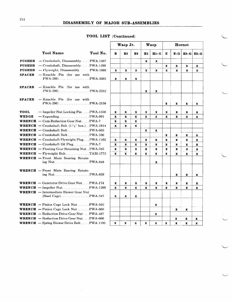
212DISASSEMBLY OF MAJOR SUB-ASSEMBLIES
TOOL LIST (Continued)
PUSHER
PUSEER
PUSEER
SPACER
SPACER
SPACER
TOOL
WEDGE
WRENCE
WRENCE
WRENCE
WRENCH
WRENCH
WRENCE
WRENCE
WRENCE
WRENCE
WRENCE
WRENCE
WRENCH
WRENCE
WRENCE
WRENCE
WRENCE
WRENCH
WRENCE
Tool Narne Tool No.
- Crankshaft, Disassembly. . . . .PWA-1387- Crankshaft, Disassembly. . . . .PWA-1388- !'lyweight, Disassembly PWA-1068- Knuckle Pin (for use with
PWA-296). . . PWA-2093
- Knuckle Pin (for use withP W A - 2 9 6 ) . . . . . . P W A - 2 2 5 2
- Knuckle Pin (for use withPWA-296) . PWA-2530
- Impeller Nut Locking Pin. . . . PWA-1558- E x p a n d i n g . . . . . . . P W A - 9 9 1- Cam Reduction Gear Nut. . . . PWA-7- Crankshaft BoIt ( I t6" hex.) . . PWA-1914- Crankshaft BoIt . . PWA-603- Crankshaft Bolt . . PWA-106- Crankshaft Flyweight PIug. . . PWA-I102- Crankshaft Oil Plug. . . . PWA-?- Floating Gear Retaining Nut. . PWA-345- Flyweight Bolt . . .TAM-1773- Front Main Bearing Retain-
i n g N u t . . . . P W A - 6 4 8
- Front Main Bearing Retain-i n g N u t . . . . P W A - 6 5 9
- Generator Drive Gear Nut. . . . PWA-174- Impeller Nut PWA-1269- fntermediate Blower Gear Nut
(Steel Cage) . PWA-347
- Pinion Cage Lock Nut. " PWA-502- Pinion Cage Lock Nut. . PWA-660- Reduction Drive Gear Nut. . PWA-487- Reduction Drive Gear Nut . PWA-660- Spring Blower Drive Bolt. . . . . PWA-1195
Wasp Jr. Wasp Ilornet
B 82 B3 E I H l . G E E . G E2- G E3- G
x xx x x x
x x x x x x x x x
x x x
x x
x x x x
x x x x x x x x xx x x x x x x x xx x xx x x
x xx x x x
x x x x x x x x xx x x x x x x x xx x x x x x x x xx x x x x x r x x
x
x x x
x x x x x x x x xx x x x x x x x x
x x x
xx x
xx x x
x x x x x x x x x
301
CHAPTER III
CLEANING
General-Two methods of cleaning are generallyemployed in preparing the parts of a disassembledengine for inspection and repair. It is custom-ary to degrease all the parts of the engine assoon as the disassembly has been completed. Itwill be found that the usual degreasing methodswill also be quite effective in removing any softsludge carbon deposits. However, in the caseof hard carbon deposits, such as are found on thepiston assembly, a decarbonizing process is re-quired. Great care should be used in separatingthe magnesium parts from the steel and alumi-num parts. MAGNESIUM PARTS SHOULDALWAYS BE CLEANED WITH A NEU-TRAL, NON-CORROSIVE, DEGREASINGMEDIUM.
Degreastng-The removal of grease and softcarbon compounds may be accomplished byspraying with gasoline, kerosene, or a whitefurnace oil. Due to the inflammabilitv of thefirst two named washing mediums, moit opera-tors prefer to use a high grade white furnace oilof 38-40 specific gravity. The parts may beeither immersed in the oil or sprayed in a pro-tected hood with the oil and compressed air(see Figs. 301-302). For many of the parts ofthe engine, this method of cleaning will be foundsatisfactory. A vapor condensate method ofcleaning has been developed by the Detroit RexProducts Company, 13007 Hillview Avenue,Detroit, Michigan. In this method the vaporfrom a tank of steam heated "Perm-A-Clor"
condenses on the cool parts and washes off allthe grease, leaving the parts perfectly dry as theyare removed from the chamber. In this process,as well as other methods which leave the partsunprotected, the cleaned parts should besprayed with a light oil as soon as they are washedto prevent rusting.
Decarbonlzlng-Most of the decarbonizing so-lutions on the market also remove the unbakedenamel from the engine parts. A great varietyof commercial preparations are available, some ofwhich will attack aluminum and magnesiumparts if they are allowed to stand too long in thesolution. It is urged that the operator proceedwith caution in trying out unfamiliar decarboniz-ing agents and follow carefully the manufac-turer's instructions governing the use of the par-ticular solvent. In general, these solutions maybe divided into two classes-those that use wateras a solvent and those that use'a hydrocarbonsolvent, such as kerosene. Magnesium partsshould never be cleaned in any decarbonizingsolution of caustic soda base, or in any processin which water may accumulate in the bottom
of the cleaning tank. It ls very irnportantthat leaded sllver rnaster rod bearlngs arenot subjected to any cleanlng bath otherthan whlte furnace oll, or lts equlvalent.
Two successful decarbonizing agents known as"Penetrol" and "Carbrax" that are widely usedfor removing hard carbon deposits are producedby the Turco Products Company, 6135 SouthCentral Avenue, Los Angeles, California. Inthe use of these products, the manufacturer's in-structions for mixing the compound to the properstrength should be closely followed. The secondnamed agent, "Carbrax", has been found particu-larly effective in removing the hard carbon depos-its from pistons with a minimum of damage tothepiston and a minimum of hand labor. It shouldnot be used for other aluminum or magnesiumparts.
Another chemical compound which has provedeffective is "Oakite", manufactured by OakiteProducts, Incorporated, 22 Thames Street, NewYork City.
When a decarbonizing agent other than awhite furnace oil, or its equivalent, is used, theparts should be washed thoroughly in hot waterto remove any trace of the cleaning agent. Ifthis is not done, the remaining solution may com-bine with the moisture in the lubricating oil whenthe engine is returned to service and may causeviolent foaming of the oil, with a resulting dis-charge of oil from the breather pipes.
Cleanlng Proced.ure-After the external sur-faces of the parts are cleaned, a particular effortshould be made to insure that all the internalpassages of the engine are thoroughly cleanedand blown out with compressed air. Particularattention should be paid to the oil passages of thecrankshaft, blower, and rear section. A sufficientnumber of the oil passage plugs should be re-moved to facilitate the cleaning and inspectionof the oil passages, fhen the degreasing fluid shouldbe forced under pressure through each of thepassages, and the system blown out with com-pressed air.
Pistons should be immersed in the cleattittgsolution until the carbon has been softened sothat it can be wiped off or removed with a softmetal or wood scraper. Particular care shouldbe taken in cleaning the carbon from the ringgrooves to prevent damage to the grooves. Al-though some cleaning solutions are very effectivein removing the carbon from the inside of thepistons, sandblasting of the inside surfaces isgenerally necessary in order that a thorough in-spection may be made for cracks.
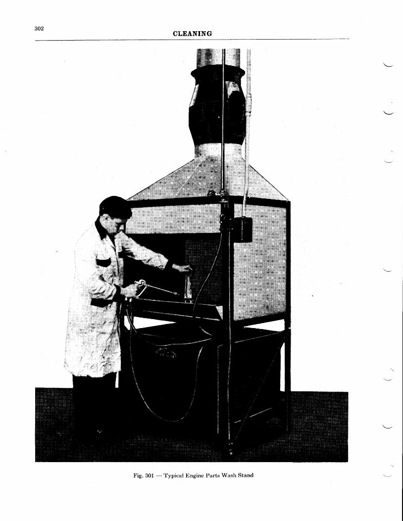
302CLEANING
Fig. 301 - Typical Engine Parts Wash Stand
303CLEANING
When the pistons are sandblasted, the pistonpin bosses should be closed off with rubber plugs.'Ihe sandblasting should not be more than neces-sary to remove the carbon, as excessive blastingsometimes tends to make small cracks invisible.After sandblasting, the oil drain holes in the oilring grooves should be cleaned out. The use of asoft wire brush on non-bearing surfaces is permis-sible. Do not disturb the polished glaze formedon the outside diameter of the piston and the in-side diameter of the piston pin bosses. The out-side of the cylinders may be sandblasted to re-move the enamel before repainting. When theoutside of the cylinder is sandblasted, the sparkplug bushing, push rod cover tube gland, androcker shaft inserts should be protected withrubber plugs, and the rocker box covers should beinstalled. When the inside of the exhaust portis sandblasted, the exhaust valve seat and guideshould be protected with a discarded valve. It isrecommended that only a fine grade of sand beused during the sandblasting operation. Theuse of steel grit or coarse sand is dangerous.The sandblasting should be done uniformly overthe entire surface and the nozzle should not beheld in one place so as to cause excessive erosionof the metal. It should be remembered thatcontinual sandblasting of the cooling fins willeventually wear the fins away and impair theircooling efficiency.
The inside of the cylinder head should be sand-blasted to remove the carbon and permit athorough inspection of this surface. During thesandblasting, the threaded holes in the sparkplug bushings should be protected with rubberplugs or with a set of discarded spark plugs.The barrel of the cylinder is protected with arubber sleeve. It is permissible to sandblast thevalve seats. This is often desirable. as it cuts thecarbon or glaze that is apt to form'on the seats,particularly the exhaust, and facilitates recon-ditioning. The ends and insides of the valveguides should be protected with rubber plugs,however.
Atry hard carbon remaining on the head of thevalve after removal from the cleaning solutionmay be removed with a fine wire brush. It ispermissible to sandblast the exhaust valve pro-viding that a very fine grade of sand is used andthe stellite face of the valve and the valve stemare protected. It is not advisable to sandblastthe intake valve as sandblasting removes the
outside coating which tends to protect the headfrom further corrosion. Very little corrosiontakes place on the head of the exhaust valve.
Ball and roller bearings should be cleaned witha neutral cleaning solution. In cases where hardcarbon has been deposited in the bearing, it maybe immersed in "Penetrol", or any carbon solventthat will not attack the bearing or the retainer.Most bearing trouble is caused by the entry ofdirt into the bearing. The cleaning of a bearingis a particular, painstaking job, and should bedone with complete thoroughness and caution.
Anti-friction bearings are very susceptible tomagnetization, both in transit and storage, andwhile running in the engine. Any magnetizationof the bearing will cause minute magnetic parti-cles to adhere to the balls and the races and willcause scoring of these parts during operation.It is, therefore, recommended that all bearingsbe demagnetized by passing them through ademagnetizer, and thoroughly washed and oiledbefore installing them in an engine. This appliesto both new and used bearings. Non-dernounta-ble bearings are demagnetized as an assembly.With the demountable type bearings, the partsare passed through the demagnetizer separately.Large bearings should be rotated as they are beingbrought out of the demagnetizer.
After removal from the cleaning solution, thebearing should .be washed and blown out withcompressed air. When blowing out the bearingwith compressed air, hold both races to preventturning of the bearing. DO NOT ALLOW THEBEARING TO SPIN. Spinning of the bearingin a dry condition will cause scoring of the races.The cleaning of the bearing should be continueduntil the bearing runs smooth when well oiled.A dry bearing will often appear loose and defec-tive. When the bearing has been cleaned, itshould be oiled, wrapped in waxed paper and putin a box to prevent the entry of dirt. A cleanbearing should never be allowed to lie exposedon the work bench. Strict observance of theseprecautions will keep bearing trouble down to amrnlmum.
Leaded master rod bearings are cleaned byflowing a white neutral furnace oil over the sur-face. Do not wipe with a rough cloth. Clean-ers, such as "Penetrol", "Oakite", etc. willremove the lead from the bearing surface.
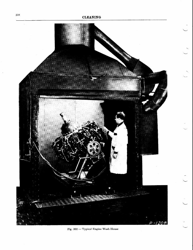
304CLEANING
Fig. 302 - Typical Engine Wash Ffouse
401
CEAPTER IV
INSPECTION
GENERAL INFORMATION
Thorough and intelligent inspection of all theengine parts, is the controlling factor in efficientand dependable overhaul work, and too muchimportance cannot be placed on careful examina-tioir, and the decisioni it involves. The fulfill-ment of these requirements at overhaul cannot beaccomplished solely from any instructions thatmay be presented. Instructions are necessary,but their main importance in many instanceswill be to supplement the judgment and experi-ence that a qualified inspector gains after yearsof this work. For less experienced personnel,the procedure described in this chapter shouldbe closely followed.
That portion of the Overhaul Shop devotedto this work should be so located as to receive themaximum of natural illumination, and shouldprovide sufficient space so that all engine partscan be arranged on an inspection table at thesame time. With all the parts arranged on onetable, the inspector may make reference toother component parts which may be affectedby a worn part. In this manner it is often possi-ble to determine at once the cause of any ab-normal wear, and to judge the condition of theengine as a whole as compared with other engineshaving the same amount of service.
During the inspection procedure the inspectorshould check and record the total time of majorengine parts, retiring from service, at the speci-fied time, &try part for which a definite life hasbeen established. If a part requires repair, a tagshould be attached to it, describing the worknecessary for reconditioning the part. Wherethe reconditioning affects a fit or clearance, thetag should remain attached to the part until finalassembly. This will serve as a warning to checkthe fit or clearance with its adjacent part orparts.
Scratched or scored bearing surfaces and bush-ings should be routed to the Repair Departmentfor correction as described in Chapter V. Theparts should then be reinspected and the inspec-tor should make certain that involved clearanceshave not been adversely affected.
PHYSICAL INSPECTION
The physical inspection of the engine involvescertain procedures that are common to similarparts and areas of the various detail parts andsub-assemblies.
To eliminate excessive repetition of instruc-tions, the following inspection procedure will begeneral to the parts specified, and should be per-
The typical engine inspection form, shown inthis chapter, is suggested for use in the averageoverhaul shop. This form rnay be amended tosuit individual practice and conditions. A recordof the wear and clearances, also pertinent infor-mation concerning the condition of the compon-ent parts of the engine, should be made by theinspector on these inspection forms. Instruc-tions for the reconditioning or replacement of apart should be included when either of these twoprocedures is found necessary. From the infor-mation recorded by the inspector, it should bepossible for workmen to determine readily whatrepair operations or replacements are necessary.
Clearance measurements are for the most partmade with micrometers or feelers. When feelersare used for determining clearances, the finalsize of feeler should be a reasonably snug fit.Where extremely accwate measurements are de-sirable, micrometers must be used. The back-Iash of all gears should be measured with a dialindicator suitably mounted, so that the plungerwill rest at the same distance from the center ofthe gears as that of its pitch diameter. Pluggages are furnished for certain functions, and areof the "NO GO" and "GO" types, the proper fitbeing obtained when the "GO" end fits and the"NO GO" will not enter the holes
The inspection procedure should include themeasurement of all the fits and clearances indi-cated by reference numbers and arrows on theClearance Charts at the back of this manual,or on large wall charts where these are available.The desired fit or clearance values will be foundopposite the corresponding reference numbers inthe Service Table of Clearances, also includedat the back of this manual. The ClearanceTables are self-explanatory as to method of useand contain reference numbers coffespondingto those on the Clearance Charts; minimum andmaximum limits for the desired fit or clearanceat each location, and replacement limit figures.
Inspection of engine parts is divided into twocategories, "Physical" and "Magnaflux" inspec-tion. These two methods of inspection are treat-ed separately in the instructions which follow.
PROCEDURE-GENERAL
formed in conjunction with such other inspectionas may be prescribed for the same parts.
Flts and Clearances-Check all backlash, fitsand clearance figures, the locations of which areindicated on the Clearance Charts.
Studs-Examine all studs for stretch, cross-
402INSPECTION
threading, mutilation and looseness in theirrespective locations.
Liners-Examine for flaking, pitting, galling,excessive wear and looseness with mating parts.
Bushlngs-Examine for cracks, mutilation, scor-irg, indications of overheating, looseness andexcessrve wear.
Crankcases, Brackets, Adapters, Surnps,Cover Plates, Etc.-Inspect for cracks, nicks,breaks, smoothness of mounting flanges and part-ing surfaces, obstructions in drilled passages,condition of paint, tightness of plugs, and mutila-tion of internal threads in tapped holes.
Gears-Examine for evidence of improper toothbearing, pitting, fatigue cracks, excessive wearand burrs.
Shafts-Examine for straightness, condition ofthreads and splines, smoothness of bearing journ-als, excessive wear and fatigue cracks.
Shafts may be examined for straightness byrolling on a plane surface, by rolling bearing sur-faces on (rV" blocks and checking for run-outwith a dial indicator, or in some cases on lathecenters.
Plpes - Inspect all oil pipes for dents, cracks,nicks, and condition of their flanges (if provided).It is important to check all oil pipes that fit in amating bracket or hole in crankcase for any loose-ness which might result in loss of oil pressure.
Rivets-Examine rivets for secure anchorage.
Otl Seal or Transf er Rings (Plston RlngType)-If oil seal or oil transfer rings are in goodcondition and show no appreciable wear or loss oftension, it is recommended that they be continuedin service. When the rings are worn, the carriersshould be carefully inspected for wear and rough-ness.
PHYSICAL INSPECTION
Contained in the following paragraphs are thedetail inspection instructions for engine partswhich cannot be classified or completely coveredin "Physical Inspection Procedure--General".To assist in determining what parts are to beinspected in accordance with the instructionsgiven under the aforementioned title, a paragraphentitled "General" which lists these parts,appears directly following each major sub-assembly title. In a few instances the parts soIisted will require additional inspection and, insuch cases, the procedure is described in a subse-quent paragraph.
Otl Seal or Transfer Ring Bearing Surfaces-Oil seal or transfer ring surfaces and liners shouldbe checked for excessive grooving. When thewear from the rings has reached a maximum of.003" on the I.D., or when wear has resulted in aridge of .0015" at any one location, the surfaceor liner should be reground to accommodateoversize rings.
Antl-Frlctlon Bearlngs-,Some types of currentbearings can be completely disassembled. Innerand outer races, as well as individual rollers orballs, of such bearings can be thoroughly in-spected and may be magnafluxed if desired. Ifrnagnafluxed, extrerne care should be exer-clsed to rnake certain that all the parts arecornpletely dernagnetlzed before r€&ss€rn-bly. Inspect the races and rollers or balls forsigns of pitting, galling, scoring, flaking and ex-cesslve wear.
Where roller or baII bearings are of a type thatcannot be completely disassembled, or can beonly partly disassembled, the bearings should bethoroughly cleaned and visually inspected as faras possible. An effort should be made to examinecarefully inner and outer races and the rollers orballs for the conditions mentioned in the preced-ing paragraph. The bearings should then beoiled with a light oil and checked for smoothness.Dry bearings are quite apt to feel rough andsound noisy when turned. Inspec{ ball or rollerretainers for cracks or defects. loose rivets andsigns of corrosion.
The inner diameter of inner races and the outerdiameter of outer races, should be examined forindications of excessive spinning. Such an indi-cation warrants an investigation of involved fits.
Radial and axial wear of bearings is usuallynegligible if the bearings are satisfactory in otherrespects. With the exception of impeller androcker arm bearings, for which limits are specifiedin this chapter, bearings may be continued inservice as long as they appear in good conditionand turn smoothlv.
PROCEDURE-DETAIL
To illustrate the foregoing, under the headingof "Front (Nose) Section-Wasp Jr.", in the firstparagraph which follows, the Thrust BearingLiner appears. By referuing back to "Liners"
under "Physical Inspection Procedure - Gen-eral", instructions for the inspection of thispart may be found. Likewise, the "Thrust
Bearing Cover" appears in the same paragraph.As this assembly consists of a cover plate and aliner, its inspection may be accomplished asdescribed under these respective headings in"Physical Tnspection Procedure - General".
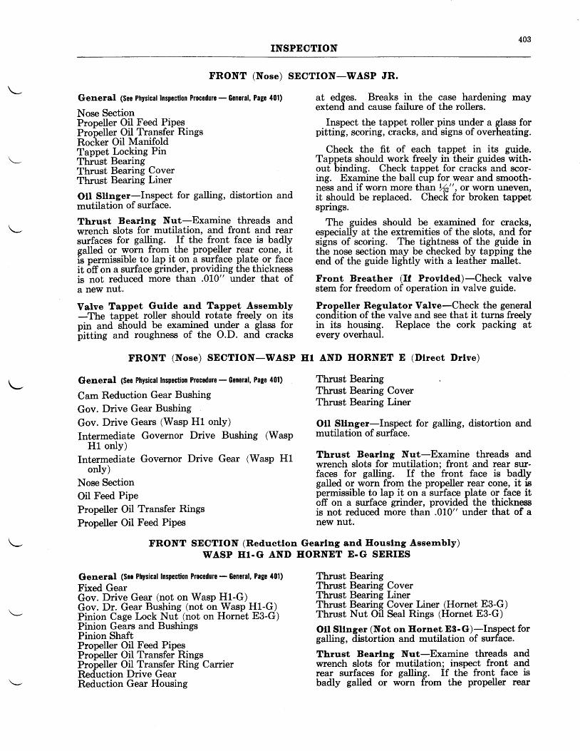
403INSPECTION
FRONT (Nose) SECTION-WASP JR.
General (See Physical Inspection Procedure - General, Page 401)
Nose SectionPropeller Oil Feed PipesPropeller Oil Transfer RingsRoc-ker Oil ManifoldTappet Locking PinThiust BearingThrust Bearing CoverThrust Bearing Liner
Otl Sltnger-Inspect for galling, distortion andmutilation of surface.
Tb.rust Bearlng Nut-Examine threads andwrench slots for mutilation, and front and rearsurfaces for galling. If the front face is badlyealled or worn from the propeller rear cone, itils permissible to lap it on a surface plate or faceit otr on a surface grinder, providing the thicknessis not reduced more than .0L0" under that ofa new nut.
Valve Tappet Gulde and Tappet Assernbly-The tappet roller should rotate freely on itspin and should be examined under a glass foriritting and roughness of the O.D. and cracks
FRONT (Nose) SECTION-WASP IIr
Gleneral (See Physical Inspection Procedure - General, Page 401)
Cam Reduction Gear Bushing
Gov. Drive Gear Bushing
Gov. Drive Gears (Wasp H1 only)
Intermediate Governor Drive Bushing (WaspH1 only)
Intermediate Governor Drive Gear (Wasp H1only)
Nose SectionOil Feed Pipe
Propeller Oil Transfer Rings
Propeller Oil Feed Pipes
at edges. Breaks in the case hardening mayextend and cause failure of the rollers.
Inspect the tappet roller pins under a glass forpitting, scoring, cracks, and signs of overheating.
Check the fit of each tappet in its guide.Tappets should work freely in their guides with-out binding. Check tappet for cracks and scor-ing. Examine the baII cup for wear and smooth-ness and if worn more than )(2", or worn uneven,it should be replaced. Check for broken tappetspnngs.
The guides should be examined for cracks,especially at the extremities of the slots, and forsigns of scoring. The tightness of the guide inthe nose section may be checked by tapping theend of the guide lightly with a leather mallet.
Front Breather (If Provlded)-Check valvestem for freedom of operation in valve guide.
Propeller Regulator Valve-Check the generalcondition of the valve and see that it turns freelyin its housing. Replace the cork packing atevery overhaul.
AND HORNET E (Dlrect Drlve)
Thrust BearingThrust Bearing CoverThrust Bearing Liner
Otl Sltnger-Inspect for galling, distortion andmutilation of surface.
Thrust Bearlng Nut-Examine threads andwrench slots for mutilation; front and rear sur-faces for galling. If the front face is badlygalled or worn from the propeller rear cone, it ispermissible to lap it on a surface plate or face itoff on a surface grinder, provided the thicknessis not reduced more than .010" under that of anew nut.
\-'
FRONT SECTION (Reductlon Gearlng and Ilouslng Assembly)WASP HT.G AND EORNET E.G SERIES
Gleneral (See Physical lnspection Procedure - General, Page 401)
Fixed GearGov. Drive Gear (not on Wasp H1-G)Gov. Dr. Gear Bushing (not on Wasp H1-G)Pinion Cage Lock Nut (not on Hornet E3-G)Pinion Gears and BushingsPinion ShaftPropeller Oil Feed PipesPropeller Oil Transfer RingsPropeller Oil Transfer Ring CarrierReduction Drive GearReduction Gear Housing
Thrust BearingThrust Bearing CoverThrust Bearing LinerThrust Bearing Cover Liner (Hornet E3-G)Thrust Nut Oil Seal Rings (Hornet E3-G)
Otl Sllnger (Not on Hornet E8-G)-Inspect forgalling, distortion and mutilation of surface.
Thrust Bearlng Nut-Examine threads andwrench slots for mutilation; inspect front andrear surfaces for galling. If the front face isbadly galled or worn from the propeller rear
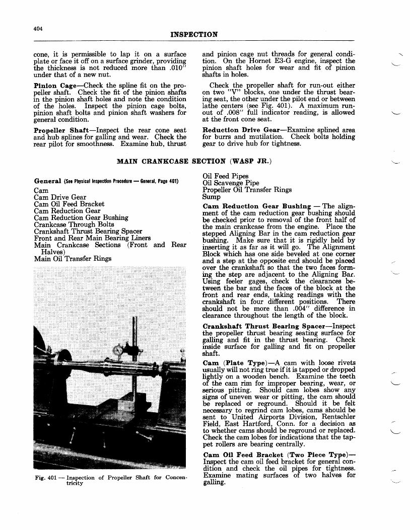
404INSPECTION
cone, it is permissible to lap it on a surfaceplate or face it off on a surface grinder, providingthe thickness is not reduced more than .010"under that of a new nut.
Plnlon Cage-Check the spline fit on the pro-peller shaft. Check the fit of the pinion shaftsin the pinion shaft holes and note the conditionof the holes. Inspect the pinion cage bolts,pinion shaft bolts and pinion shaft washers forgeneral condition.
Propeller Shaft-Inspect the rear cone seatand hub splines for galling and wear. Check therear pilot for smoothness. Examine hub, thrust
and pinion cage nut threads for general condi-tion. On the Hornet E3-G engine, inspect thepinion shaft holes for wear and fit of pinionshafts in holes.
Check the propeller shaft for run-out eitheron two "V" blocks, one under the thrust bear-ing seat, the other under the pilot end or betweenlathe centers (see Fig. 401). A maximum run-out of .008" full indicator reading, is allowedat the front cone seat.
Reductlon l)rlve Gear-Examine splined areafor burrs and mutilation. Check bolts holdinggear to drive hub for tightness.
MAIN CRANKCASE SECTION (WASP JR.)
General (See Physical Inspection Procedure - Scncral, Page 401)
CamCam Drive GearCam Oil Feed BracketCam Reduction GearCam Reduction Gear BushingCrankcase Through BoltsCrankshaft Thrust Bearing SpacerFront and Rear Main Bearing LinersMain Crankease Sections (Front and Rear
Halves)Main Oil Transfer Rings
Oil Feed PipesOil Scavenge PipePropeller Oil Transfer RingsSumpCam Reductlon Gear Bushlng - The align-ment of the cam reduction gear bushing shouldbe checked prior to removal of the front half ofthe main crankcase from the engine. Place thestepped Aligning Bar in the cam reduction gearbushing. Make sure that it is rigidly held byinserting it as far as it will go. The AlignmentBlock which has one side beveled at one cornerand a step at the opposite end should be placedover the crankshaft so that the two faces form-ing the step are adjacent to the Aligning Bar.Using feeler gages, check the clearances be-tween the bar and the faces of the block at thefront and rear ends, taking readings with thecrankshaft in four different positions. Thereshould not be more than .004" difference inclearance throughout the length of the block.
Crankshaft Thrust Bearlng Spaeer-Inspectthe propeller thrust bearing seating surface forgalling and fit in the thrust bearing. Checkinside surface for galling and fit on propellershaft.Cam (Plate Type)-A cam with loose rivetsusually will not ring true if it is tapped or droppedlightly on a wooden bench. Examine the teethof the cam rim for improper bearing, wear, orserious pitting. Should cam lobes show anysigns of uneven wear or pitting, the cam shouldbe replaced or reground. Should it be feltnecessary to regrind cam lobes, cams should besent to United Airports Division, RentschlerField, East Hartford, Conn. for a decision asto whether cams should be reground or replaced.Check the cam lobes for indications that the tap-pet rollers are bearing centrally.
Cam Otl Feed Bracket (Two Pleee Type)-Inspect the cam oil feed bracket for general con-dition and check the oil pipes for tightness.Examine mating surfaces of two halves forgalling.
Fig. 401 - Inspection of Propeller Shaft for Concen-tricity
405INSPECTION
Examine the condition of the floating typemain oil transfer rings and their fit on the camhub. Check their side clearance and examine forconcentricity. It is not necessary to replacethis type of ring at each overhaul unless wornexcessively. However, it is well to lap bothplate and ring contact surfaces at each overhaul.
General (See Physical Inspcction Procedure - Gonsral, Page 401)
Bearing Support PlateCam BearingCam Drive GearCam Oil Feed BracketCam Reduction GearCam Reduction Gear BushingsCrankcase Through BoltsFront and Rear Main Bearing LinersFront Main Bearing Retaining NutGovernor Idler Gear (Hornet E-G, E2-G, and
E3-G)Governor Idler Gear Bushing (Hornet E-G, Ez-G,
and E3-G)Front and Rear Main Crankcase SectionsMain Oil Transfer RingsOil Feed PipesOil Scavenge PipesReduction Drive Gear BearingReduction Drive Gear Bearing LinerSump
Carn Drlve Gear - Inspect splined area forgalling and for fit on crankshaft.
Cam (Shelf Type)-Inspect cam teeth forimproper bearing, wear, and signs of pitting.Check the inside bearing surface for smooth-ness. Should the cam lobes be worn unevenly
Cam Otl Feed Bracket (One Plece Type)-Check the fit of the one-piece type bracket onthe cam hub. Examine the steel bushing whichis riveted inside the casting for general condi-tion. This part cannot be removed for in-spection.Cam Spacer-Examine for galling, distortion,and warping.
or show signs of serious pitting, the cam shouldbe replaced or reground.
Valve Tappet Gulde and Tappet Assembly-The tappet roller should turn freely on its pin.Examine under a glass for pitting and roughnessof the O.D. and cracks at edges. Breaks incase hardening may extend and cause failure ofthe rollers. Inspect the tappet roller pins undera glass for pitting, scoring, cracks, and signs ofoverheating.
Check the fit of each tappet in its guide.Tappet should work freely in the gurde withoutbinding. Check tappet for cracks and scoring.Examine the ball cup for wear and smoothnessand if worn more than Ye" ot uneven, it shouldbe replaced.
The gurdes should be qxamined for cracks,especially at the extremities of the slots, and forsigns of scoring. The tightness of the guide inthe crankcase may be checked by tapping theend of the guide lightly with a leather mallet.
Sump-On engines having the propellerregulator valve located in the sump, follow theinstructions for inspection of this part as givenunder the Front (Nose) Section for Wasp Jr.engines.
MAIN CRANKCASE SECTION-WASP ET AND HORNET E SERIES( Dlrect Drlve and Geared)
\-
CYLINDERS-ALL MODELS
General (Sec Physical Inspection Proccdure - General, Page 401)
Push Rod Cover GlandsRocker BearingsRocker Box CoversRocker Box Oil Drain or Pressure PipesRocker Shaft Inserts (in Cylinder Head)Spark Plug Bushings
Cyltnder Heads-As recommended in ChapterIII, "Cleaning", cylinders should be sandblastedon the outside to remove old enamel beforerepainting. This also proves an effective meansof disclosing cracks which might not otherwisebe apparent. If cylinders are not to be repainted,closely examine the enamel, for breaks whichwould indicate cracks.
If two or more center head fins are crackedtheir entire length, the cylinder should be dis-
carded. Small cracks in the head fins are notcause for rejection.
Inspect the inside surface of the cylinder headand the inlet and exhaust ports for cracks.Examine the heavy strengthening rib on the frontof the valve housings and the heavy flange atthe base of the cylinder head for cracks. Ex-amine the insides of the rocker box walls forcracks.
Valve Gulde-Examine valve guides for exce-sive wear. As valve guides do not wear evenlyand become out-of-round, the flat type Maxi-mum Wear Gages are recommended for use. Themaximum width of the gage is the limit for theguide size. If this enters more than one half inchat the top or bottom of a guide, the guide shouldbe replaced.
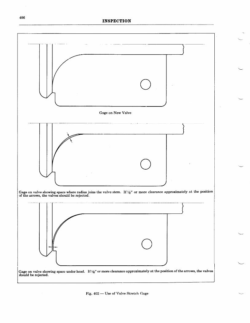
406INSPECTION
Gage on New Valve
Gage on valve showing space where radius joins the valve stem. lf ,6' or more clearance approximately at the positionof the arrows, the valves should be rejected.
Gage on valve showing space under head. If Kz'or more clearance approximately at the position of the arrows, the valvesshould be rejected.
Fig. 402 - Use of Valve Stretch Gage
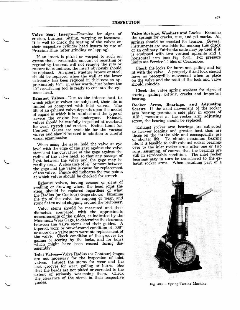
407INSPECTION
Valve Seat Inserts-Examine for signs oferosion, burning, pitting, warping -or looseness.It is well to check the seating of the valves ontheir respective cylinder head inserts- by use ofPrussian-Blue (after grinding or lapping).
If an insert is pitted or warped to such anextent that a reasonable amount of recutting orregrinding the seat will not removg thg pits ort"Jtore itJ roundness, the insert obviously shouldbe replaced. An insert, whether bronze or steel,should be replaced when the wall at the lowerextremity has been reduced in thickness to a-p-proxima[ely Yrc"; in other words, just before the15' r*s,rtfacind tool is ready to cut into the cyl-inder head.
Exhaust Valves-Due to the intense heat to*fti.tt exhaust valves are subjected, their Ii& isU*it"a as compared with inlet valves. Thelife of an exhaust valve depends upon the model6T engitt"-in which it is installed and the-!{Pe ofservicl the engine has undergone. Exh-aust'rr"t.r". should be carefully inspected at overhaulfor wear, stretch and erosion. Radius Limit (orContour) Gages are available for the variouslrutr"t aira sftoutd be used in addition to carefulvisual examination.
When using the gage, hold the valve at eyeIevel with the edge of the gage against the valverl.* and the curvature of the gage against theiuai"t of the valve head, so that any passage ofii?ttt between the valve and the gage -may bereadilv seen. A clearance of \2" or more betweenlfte eie" and the valve is cause for, replacementof ttr]. ialve. Figure 402 indicates the two points"l *hich valves stroda be checked for stretch.
Exhaust valves, having creases or signs ofr*.llitte ot drawing whefe the head joins thert"*, ittoUa be rbplaced regardless gf wlatthe Radius (or Contour) Gage shows. Flxaminettr. tip of the yalYq foI "rrpping or wear,. andstone flat to avoid chipping around the periphery'
Valve stems should be measured and theirdiameters compared with the appr-olimatemeasurements oi the guides, as indicated by theMuii*"- Wear Gage, to determine the clearanceU"i*""" the valve stems and their guides' Atapered, worn or out-of-round condition of .006"or more on a valve stem warrants replacement ofihe-vulve. Check condition of the grooves for
i"iti"g or scoring by- the locks, 9n4 for burrsfr-tti.ft" might hive
- been caused during dis-
assemblY.
Inlet Valves-Valve Radius (or Contour) G.agesare not necessary for the inspection of - inletlr"in.t. Inspect
-the stems foi wear and the
f,o.t groovei for wear, galling or burrg. SeeIttut t"he heads are not pi[ted or corroded to thee"le"t of seriously weakening thgm. Checkthe clearance of the stems in their respectiveguides.
Valve Sprlngs, IVashers and Locks-Examinethe spriigs f6r'cracks, rust, and pit marks. AII
springs should be checked for tension. Severalinstrriments are available for making this checkor an ordinary Fairbanks scale-may -b9 used if itis equipped witfr two vertical uprights and ahorizbntil arm (see Fig. 403). For pressurelimits see Service Tables of Clearances.
Check the locks for buns and galling and forfit tith the valve. A properly fitted Iock shouldh"n" no perceptible movement yhgn in placeotr tft" vaive arid the radii of the lock and valveshould coincide.
Check the valve spring washers for signs- ofscoring, galling, pitting,
-cracks and imperfect
bearing.
Roeker Arrns, Bearlngs, and' AdiustlngS"""-.-If the'axial movement of the rocker;r* bearing permits a side,play in excess.of.0L5", measured at the rocker- arm adjustingscrew, the bearing should be replaced.
Exhaust rocker arm bearings are subjectedto heavier loading and greater heat than arethose on the intaLe side-and consequen-tly areoT-shottet life. To obtain maximum bearingtif", it is feasible to shift exhaust rocker bearingsover to the inlet rocker arms after one or tworuns, assuming, of course,- that ttre bearings are,tiU i" servicdable condition. The inlet rockerLLutittgs may in turn be transferred to the ex-G;;t ;;ckei arms. When installing part of a
Fig. 403 - Spring Testing Machine
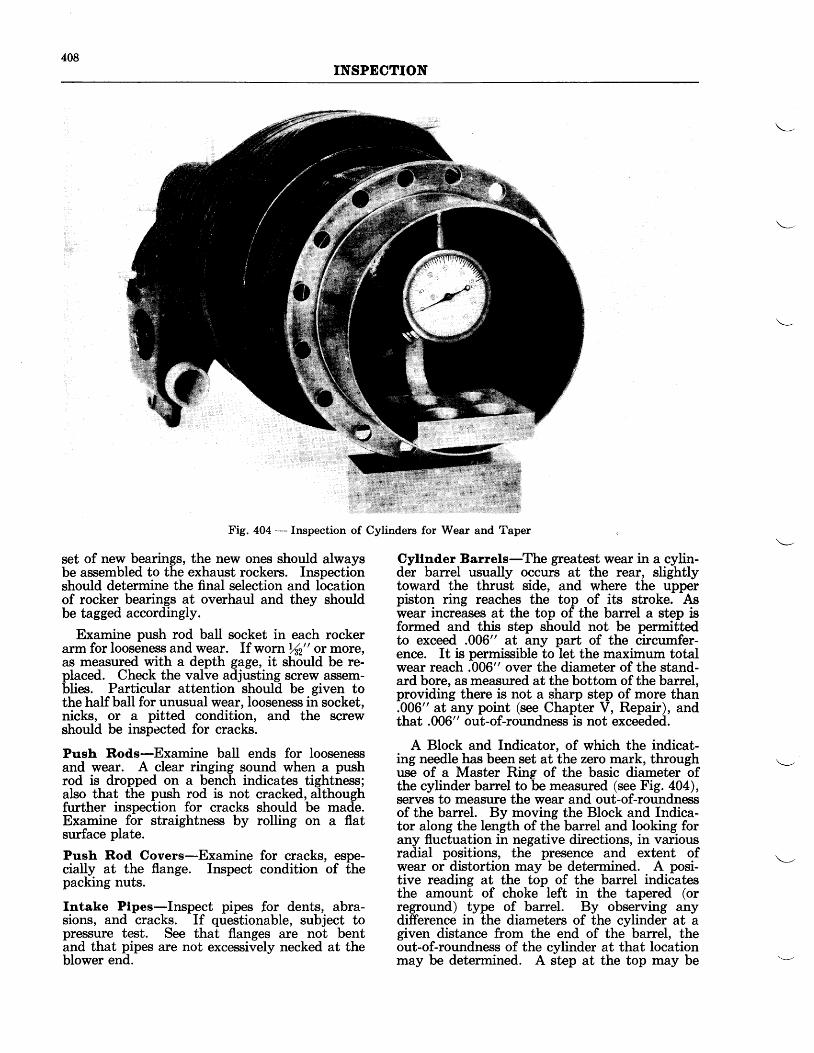
408INSPECTION
Fig. 404 - Inspection of Cylinders for Wear and Taper
set of new beariogt, the new ones should alwaysbe assembled to the exhaust rockers. Inspectionshould determine the final selection and locationof rocker bearings at overhaul and they shouldbe tagged accordingly.
Examine push rod ball socket in each rockerarm for looseness and wear. If worn %2" or more,as measured with a depth gage, it should be re-placed. Check the valve adjusting screw assem-blies. Particular attention should be given tothe half ball for unusual wear, looseness in socket,nicks, or a pitted condition, and the screwshould be inspected for cracks.
Push Rods-Examine ball ends for loosenessand wear. A clear ringing sound when a pushrod is dropped on a bench indicates tightness;also that the push rod is not cracked, althoughfurther inspection for cracks should be made.Examine for straightness by rolling on a flatsurface plate.
Push Rod Covers-Examine for cracks, espe-cially at the flange. Inspect condition of thepacking nuts.
Intake Plpes-Inspect pipes for dents, abra-sions, and cracks. If questionable, subject topressure test. See that flanges are not bentand that pipes are not excessively necked at theblower end.
Cyllnder Barrels-The greatest wear in a cylin-der barrel usually occurs at the rear, slightlytoward the thrust side, and where the upperpiston ring reaches the top .of its stroke. Aswear increases at the top of the barrel a step isformed and this step should not be permittedto exceed .006" at any part of the circumfer-ence. It is permissible to let the maximum totalwear reach .006" over the diameter of the stand-ard bore, as measured at the bottom of the barrel,providing there is not a sharp step of more than.006" at any point (see Chapter V, Repair), andthat .006" out-of-roundness is not exceeded.
A Block and Indicator, of which the indicat-ing needle has been set at the zero mark, throughuse of a Master Ring of the basic diameter ofthe cylinder barrel to be measured (see Fig. 404),serves to measure the wear and out-of-roundnessof the barrel. By moving the Block and Indica-tor along the length of the barrel and looking forany fluctuation in negative directions, in variousradial positions, the presence and extent ofwear or distortion may be determined. A posi-tive reading at the top of the barrel indicatesthe amount of choke left in the tapered (orreground) type of barrel. By observing anydifference in the diameters of the cylinder at agiven distance from the end of the barrel, theout-of-roundness of the cylinder at that locationmay be determined. A step at the top may be
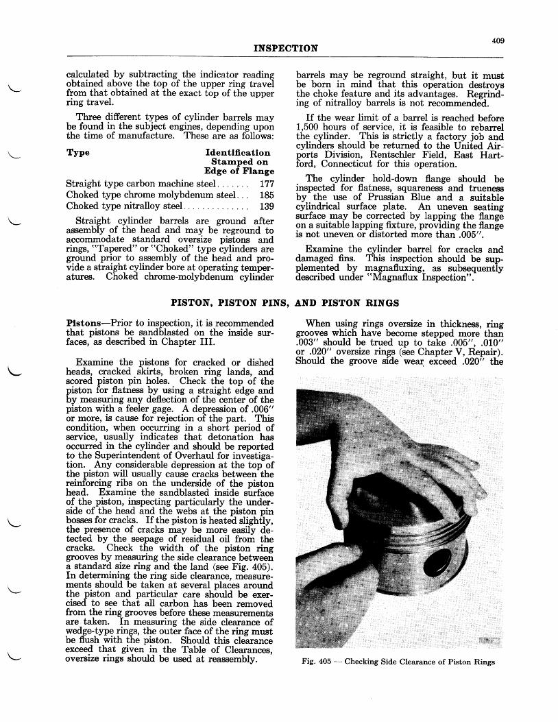
409INSPECTION
calculated by subtracting the indicator reading\ obtained above the top of the upper ring travel\-- from that obtained at the exact top of the upper
ring travel.
Three different types of cylinder barrels maybe found in the subject engines, depending uponthe time of manufacture. These are as follows:
Type IdenttffcatlonStamped on
Edge of Flange
Straight type carbon machine steel L77Choked type chrome molybdenum steel. . . 185Choked type nitralloy steel 139
Straight cylinder barrels are ground afterassembly of the head and may be reground toaccommodate standard oversize pistons andrings, "Tapered" or "Choked" type cylinders areground prior to assembly of the head and pro-vide a straight cylinder bore at operating temper-atures. Choked chrome-molybdenum cylinder
PrsToN, PrsToN PrNS,
Plstons-Prior to inspection, it is recommendedthat pistons be sandblasted on the inside sur-faces, as described in Chapter III.
Examine the pistons for cracked or dishedheads, cracked skirts, broken ring lands, andscored piston pin holes. Check the top of thepiston for flatness by using a straight edge andby measuring any deflection of the center of thepiston with a feeler gagg. $ deprgssion of .Q=06"or more, rs cause for rejection of the part. Thiscondition, when occuning in a short period ofservice, usually indicates that detonation hasoccurred in the cylinder and should be reportedto the Superintendent of Overhaul for investiga-tion. Any considerable depression at the topofthe piston will usually cause cracks between-thereinforcing ribs on the underside of the pistonhead. Examine the sandblasted inside surfaceof the piston, inspecting particularly the under-side of the head and the webs at the piston pinbosses for cracks. If the piston is heated slightiy,the presence of cracks may be more easily db-tected by the seepage of residual oil from thecracks. Check the width of the piston ringgrooves by measuring the side clearance betweena standard size ring and the land (see Fig. 405).In determining the ring side clearance, measure-ments should be taken at several places aroundthe piston and particular care shbuld be exer-cised to see that all carbon has been removedfrom the ring grooves before these measurementsare taken. In measuring the side clearance ofyed_ge-lype rings, the outer face of the ring mustbe flush with the piston. Should this clearanceexceed th.at given in the Table of Clearances,oversize rings should be used at reassembly.
barrels may be reground straight, but it mustbe born in mind that this operation destroysthe choke feature and its advantages. Regrind-ing of nitralloy barrels is not recommended.
If the wear limit of a banel is reached before1,500 hours of service, it is feasible to rebarrelthe cylinder. This is strictly a factory job andcylinders should be returned to the United Air-ports Division, Rentschler Field, East Hart-ford, Connecticut for this operation.
The cylinder hold-down flange should beinspected for flatness, squareness and truenessby the use of Prussian Blue and a suitablecyli-ndrical surface plate,. _ An uneven seatingsurface. may be corrected by lapping the flangeon a suitable lappi_ng fixture, providing the flangeis not uneven or distorted more than .005".
Examine the cylinder barrel for cracks anddamaged _fi4r. This inspection should be sup-pleme_nted by magnafluxing, as subsequent-lydescribed under "Magnaflux Inspection".
AND PISTON RINGS
When rlsing _rings -oversize in thickness, ringgrooves which have become stepped more than.003" should be trued up to take .005", .010"or .020" oversize rings (see Chapter V, Repair).Shoutd the groove side wear exceed .020r' the
\-
Fig. 405 - Checking Side Clearance of Piston Rings
410INSPECTION
piston should be scrapped, as further reductionin the inter-ring land width will weaken thelands and may cause failure.
With the wedge-type construction, it willprobably never be necessary to machine thering groove for oversize rings. If, in exceptionalcases, this does become necessary, pistons shouldbe returned to the United Airports Division,Rentschler Field, East Hartford, Connecticut,for reoperation.
Plston Plns - Prior to inspection of the pistonpins, the plugs should be removed as describedin Chapter II.
Inspect the piston pin for scoring, cracks,
excessive wear, and rust pitting. Refer toChapter V for information on piston pin types.
Plston Pln Plugs-It is permissible to re-usepiston pin plugs which have not been damagediluring rembvai and which are still within thedesire-d service limits for fit in the piston pin.The plugs are originally__installed _ previous togrinding the piston pin. When used f-or-replace-irent, [owev-er, they must be installed to theservice fit specified in the Table of Clearances toprevent swelling the end of the piston pin.
Plston Rlngs-All piston rings except the dualoil control and scraper rings are replaced ateach overhaul. These rings may be used fortwo overhaul periods provided they show noappreciable wear or loss of tension.
The Master and Articulating Rod AlignrngFixture is used for checking the master rod foralignment (bend and twist). This fixture maYbe used either with the master rod bearing andknuckle pin bushing installed or with themremoved.
- To check the rod for bend, place the
master rod on the fixture with the expandingmandrel inserted in the master rod bore. Extremecare should be exercised not to damage the leadedsurface of the master rod bearing. By adjust-ing the mandrel and jack, regulate the positionoflhe rod so that its center line is approximately45/s" above the surface plate and -parallel to it.Piice the expanding sleeve in-the piston pinbushing and expand-with its arbor -until tight.Move
-up the iirdicator until it makes contact
with the arbor 3" from the centerline of themaster rod. Remove the jack and with the lefthand move the rod up and down and record themaximum readins obtained on the dial indicator.Without movinglhe position of the dial indica-tor bracket, remove fhe master rod, reverse itsfaee, and reinstall on the fixture.- Ag"it -movethe
'rod up and down with the left hand and
observe the maximum reading on the dial indicator. A difference in the 1wo readings willindicate bend in the master rod. A maximumdifference of .005" is allowed with the indicatornlaced 3" from the centerline of the master rodior r new rod and .0L0" for a used rod. It isvery important that the rod is- parallel with thealigning fixture within this limit.
To check for twist, replace the jack and re-verse the indicator bracket so that the plungerwill bear on the bottom side of the arbor at aposition 3" from the centerline of the master rod.Move the indicator back and forth until a maxi-mum reading is obtained. Repeat this operationon the other side of the arbor and compare thetwo readings. A maximum twist of .010" at atotal distance of 6" (3" on each side of center-line) is allowed.
CRANKSEAFT AND ARTICULATTNG ROD ASSEMBLY
General (See Physical Inspection Procedure - General, Page 101)
Blower Spring Drive BoltCrankshaft BoltCrankshaft Front SectionCrankshaft Rear GearCrankshaft Rear SectionFlvweieht LinersFrbnt ind Rear Main BearingsKnuckle Pin BushingsPiston Pin Bushings
Front and Rear Maln Bearings-Inspectionof these bearings will reveal that wear occnrslsooner on the inner race than on the outer.Except for those on the early Wasp Jr. B engines,the Eearings are made with a separqble innerrace. so that it can be examined and replace-rnent made if necessary. Inspection of the innerrace will usually show that the load has beenconcentrated upon a small part of the circum-ference of the race. Viewing the shaft from therear with the crankpin uppermost, this is lo-cated at about the "five o'clock" position.
If a bright line is noticed on the loaded sideof the innlr race under one end of the rollers,the race should be turned on the shaft to bring afresh area into the loaded zorre- It is suggestedtttut the race be turned 120o, which will allowior another turning at the succeeding overhaul.lf uny pitting or flaking of the r?qelvay-is visibleio thb iraked eye, the iace should be discarded.Ordinarily the
-outer race and rollers will be in
eood condition and may be reused when a$sem-6tea with a new innei race. However, if thebearing feels rough- when-assembled with a newinner iace or if- the rollers appear pitte-d' ordamaged in any waY, the entire assembly shouldbe replaced.Master Rod-Inspect the knuckle pil holes forevidence of gallin!, ridges, scoring, burrs, andcracks. Chedi< thtfit of-the knuckle pins in-theknuckle pin holes. The measurements should betaken after any polishing operations.
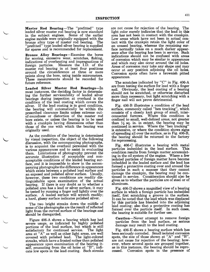
4LLINSPECTION
Master Rod Bearlng-The "prefitted" typeleaded silver master rod bearing is now standardin the subject engines. Some of the earlierengine models were originally equipped with thebronze alloy type of master rod bearing. The"prefitted" type leaded silver bearing is suppliedfor spares and is recommended for replacement.
Bronze Alloy Bearlngs-Examine the boresfor scoring, excessive wear, scratches, flaking,indications of overheating and impregnations offoreien particles. Measure the I.D. of themast"er rbd bearing in at least four positionsaround the circumference at three or morepoints along the bore, uging- inside micrometers.These measurements should be recorded forfuture reference.
Leaded Sllver Master Rod Bearlngs-Inmost instances, the deciding factor in determin-ing the further serviceability of leaded silverbeirings during inspection at overhaul is thecondition of the lead coating which covers thesilver. If the lead coating is in good condition,the bearing will automatically be within theprescribed clearance limits unless extreme out-bf-roundness or distortion of the master rodbore exists, or unless the bearing is to be usedwith a crankpin having dimensions other thanthose of the one with which the bearing wasoriginally used.
As the condition of the bearing is determinedby visual inspection, the object of the followingdiscussion, with the accompanying photographs,is to acquaint the overhaul personnel with thevarious appearances and to assist in evaluatingthem. Limitations of photography prevent theaccurate illustration of acceptable and non-acceptable conditions of the leaded bearing sur-face, and it is impossible to show in the accom-nanying photographs the difference in appearancewtriitr exists between a polished lead surface andan exposed and polished silver surface. Usually,however, these two conditions are readily dis-tinguishable upon examination of the actualbeirine. If there is any doubt as to whether apolished area has a lead or silver surface, it maybe tested by running a finger nail lightly over thesurface. A leaded surface will scratch readily;a hard, glassy surface indicates polished silver.
The two bright streaks down the middle ofsome of the photographs are the result of reflectedlieht from the curved surface of the bearings andsf,ould be disregarded.
Figure 406-A shows a bearing wtrich has- hadsevere usage, as indicated by highly polishedportions of the lead surface, but which is stillsatisfactory for continued service. The lightarea at "A" as well as other light areas, are wellcovered with polished lead. The light-coloredstreaks, which have a frosted rather than polishedappearance upon examination of the bearing it-s6lf, emanating from the oil holes at "p", indi-cate low spots in the lead coating. Such streaks
are not cause for rejection of the bearing. Thelieht color merely indicates that the lead in thisaiea has not been in contact with the crankpin.Low areas which have not been in actual con-tact with the crankpin retain the light color ofan unused bearing, whereas the remaining sur-face normally takes on a much darker appear-ance after the bearing has been in service. Suchindications should not be confused with areasof corrosion which may be similar in appearanceand which may also occur around the oil holes.Areas of corrosion may take any shape and mayoccur at any position adjoining the oil holes.Corrosion spots often have a brownish pittedappearance.
The scratches indicated by "C" in Fig. 406-Aare from testing the surface for lead with a fingernail. Obviously, the lead coating of a bearingshould not be scratched, or otherwise disturbedmore than necessary, but light scratching with afinger nail will not prove detrimental.
Fig. 406-8 illustrates a condition of the leadsurface, commonly called "hen tracking", whichconsists of a closely knit group of small, inter-connected furrows. Where this condition isconfined to small, well-defined areas, not greaterthan rA sq,. in. in extent, the bearing may becontinued in service. Where the "hen tracking"is extensive, or where the condition shows signsof spreading all over the surface, as in Fig.406-8,the-bearing should be returned to the factoryfor reprocessing.
Fig. 406-C illustrates a bearing with mqtalparticles imbedded in the lead surface. Thisiondition results from foreign matter accumulat-ing in the oil system of the engine. Where a fewisolated particles of foreign matter have becomeimbedded in the leaded surface and the lead hasformed a protective coating over and around theparticles in such a manner that they _cannotilamage the crankpin, the bearing may be con-tinued in service. Consideration should also begiven as to whether the particles are of steel or ofaluminum
Fig. 406-D shows a magnified view of a bearingsurfa-ce in which a foreign particle has imbeddeditself, first scratching a groove in the surface.It can be noted that the lead which was displacedby this particle has blended into the adjoininglead coating; also that a protective coating hasformed over the particle itself. In such cases,the bearing is suitable for further use.
Cautlon-Never attempt to remove foreignparticles from the lead surface, as seriousdamage may result to the lead coating.Fig. 406-E shows a bearing surface which has
been seriously corroded. Small isolated corrosionspots, the size of those shown at "A" and "B",
are not cause for rejection of the bearing; how-ever, where several spots are grouped together,as in this instance, the bearing should be repro-cessed. Corrosion spots in the presence of
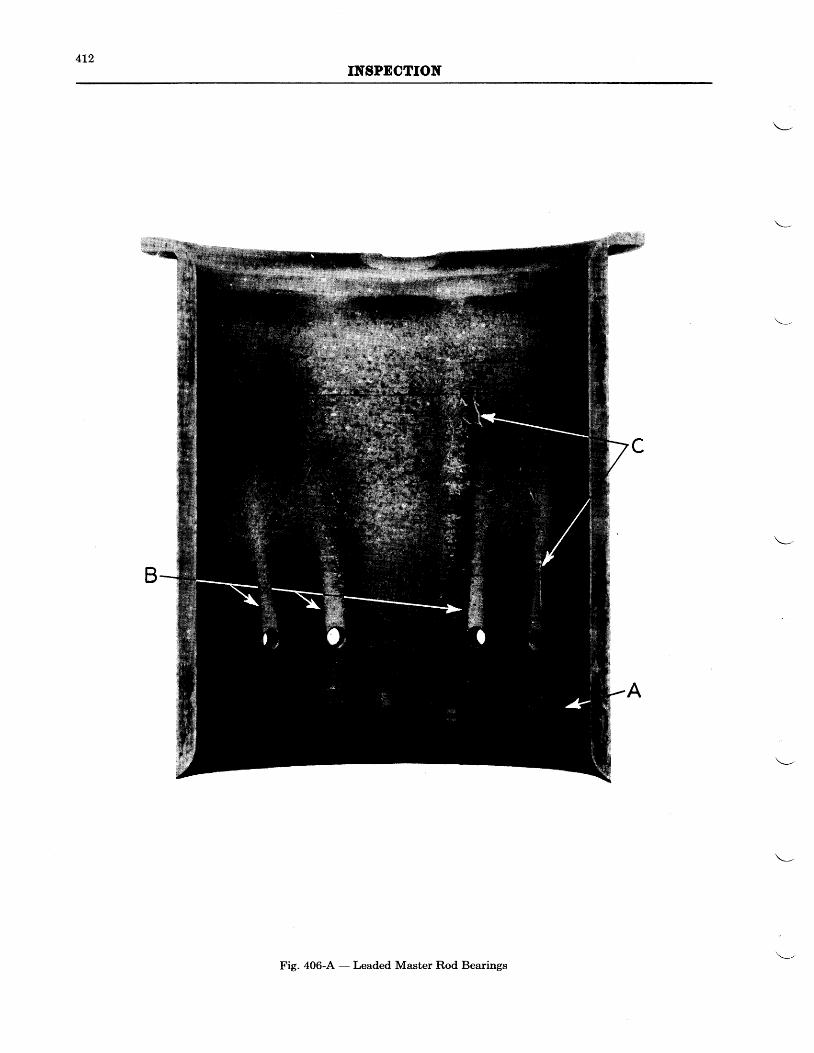
4L2INSPDCTION
Fig. 406-A - Leaded Master Rod Bearings
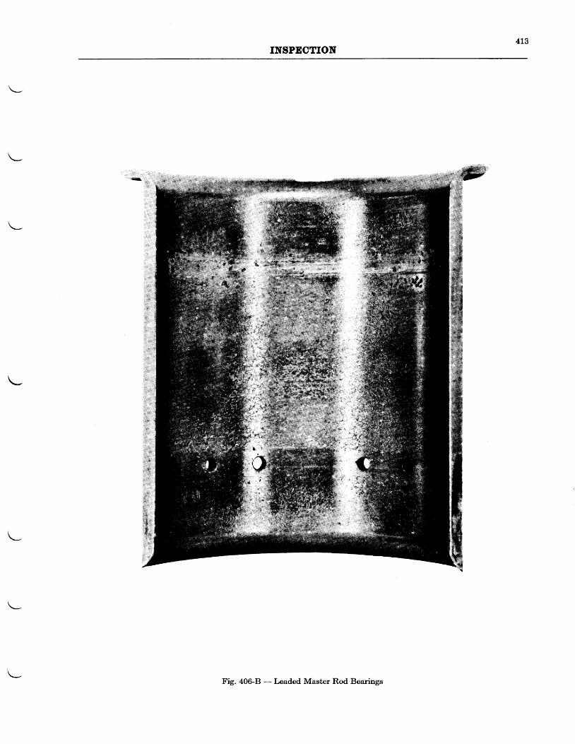
4L3INSPECTION
Fig. 406-B - Leaded Master Rod Bearings
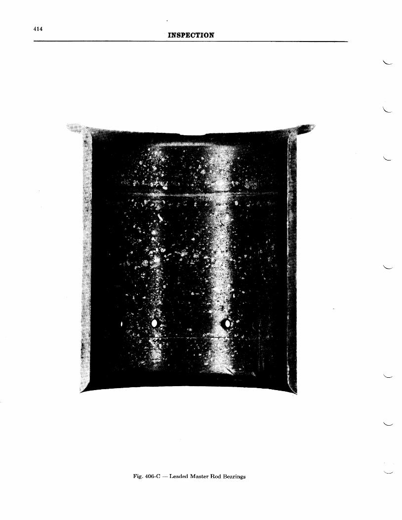
4t4INSPDCTION
Fig. 406-C - Leaded Master Rod Bearings
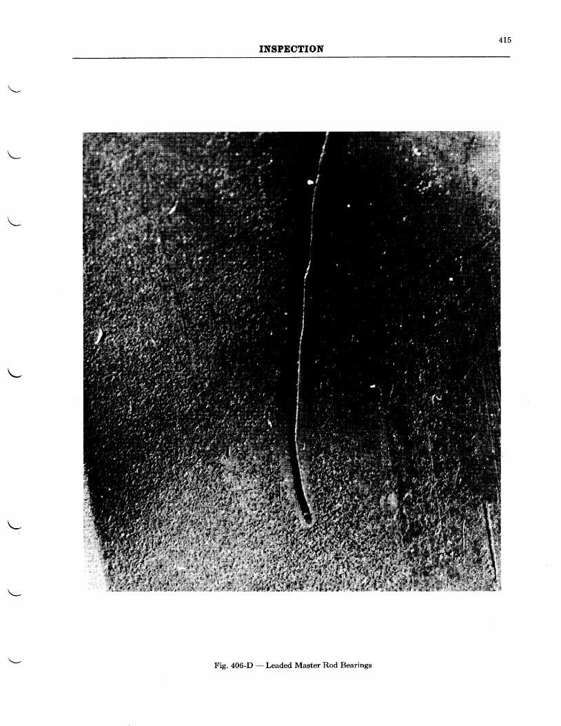
4L5INSPECTION
Fig. 406-D - Leaded Master Rod Bearings
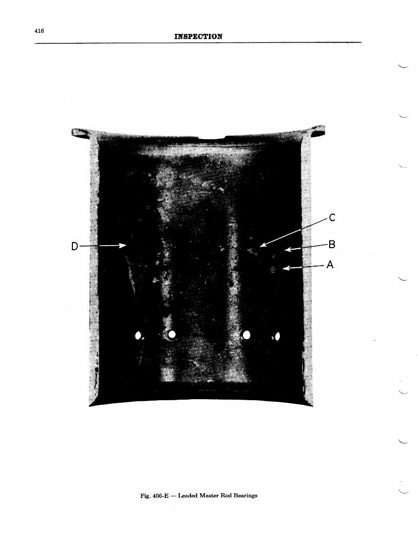
4t6IIYgPDCTION
c
B
A
Fig. 406-E - Leaded Master Rod Bearings
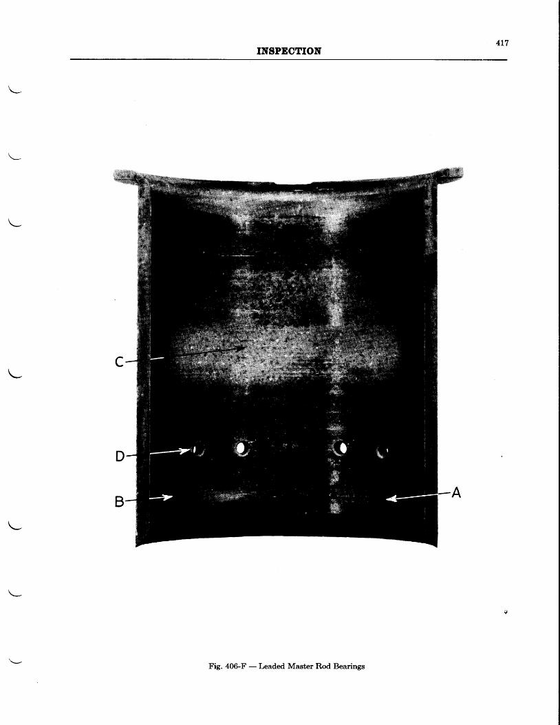
4L7INSPECTION
Fig. 406-F - Leaded Master Rod Bearings
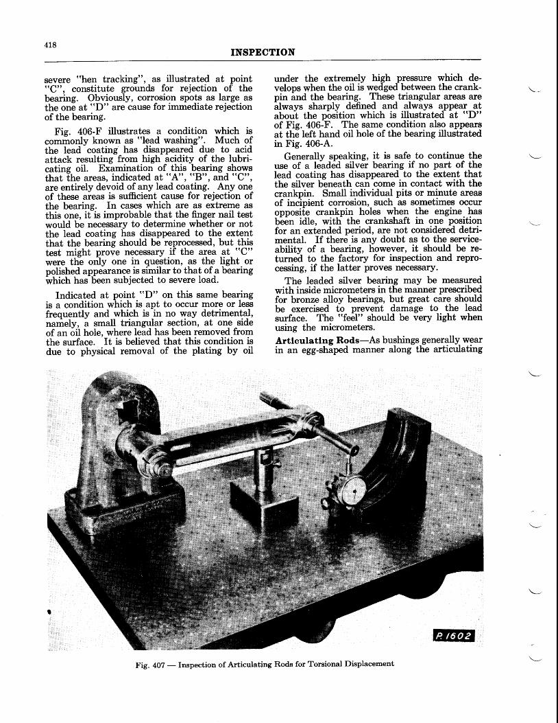
418INSPECTION
severe "hen tracking", as illustrated at point"C", constitute grounds for rejection of thebearing. Obviously, corrosion spo_ts as large asthe one at "D" are cause for immediate rejectionof the bearing.
Fis. 406-F illustrates a condition which iscomfronly known as "lead washing". Much ofthe lead coating has disappeared due to acidattack resulting from high acidity of the lubri-cating oil. Examination of thil -bpg.ring _shorvsthat [he areas, indicated at "A", "B", and "C",
are entirely devoid of any lead coating. Any oneof these areas is sufficient cause for rejection ofthe bearing. In cases which are as extreme asthis one, it is improbable that the finger nail testwould be necessary to determine whether or notthe lead coating has disappeared to the extentthat the bearing should be reprocessed, but thistest might prove necessary if the area at "C"
were ttie orily one in question, as the light orpolished appearance is similar to that of a bearingwtrictt has 6een subjected to severe load.
Indicated at point ((T)" on this same bearingis a condition which is apt to occur more or lessfrequently and which is in no way detrimentql,nariely, a small triangular section, at one -sideof an oil hole, where lead has been removed fromthe surface. It is believed that this condition isdue to physical removal of the plating by oil
under the extremely high pressure which de-velops when the oil is wedged between the crank-pin and the bearing. These triangular areas arealways sharply defined and always appear_ atabout the pbsition which is illustrated at (tD"
of Fie. 406:F. The same condition also appearsat the left hand oil hole of the bearing illustratedin Fig. 406-.4..
Generally speaking, it is safe to continue theuse of a leaded silver bearing if no part of thelead coating has disappeared to the extent thatthe silver b-eneath can come in contact with thecrankpin. Small individual pits or minute areasof inc-ipient corrosion, such as sometimes occuropposile crankpin holes when the engine hasb-e6n idle, with the crankshaft in one positionfor an extended period, are not considered detri-mental. If there is any doubt as to the service-ability of a bearing, however, it should_ be re-turned to the factory for inspection and repro-cessing, if the latter proves necessary.
The leaded silver bearing may be measuredwith inside micrometers in the manner prescribedfor bronze alloy bearings, but great care shouldbe exercised to prevent damage to the leadsurface. The "feel" should be very tight whenusing the micrometers.
Artlculatlng Rods-As bushings generally- wearin an egg-shaped manner along the articulating
Fig. 407 - Inspection of Articulating Rods for Torsional Displacement
4L9INSPECTION
rod center line, the clearance between the knucklepin and the knuckle pin bushing should beineasured by using a narrow feeler gage, or asnap gage and micrometers.
Articulating rods are checked for bend andtwist on the same fixture and in the same manneras the master rod, with the exception that thepiston pin bushing end is placed over the mandrel?see Fie. 407).The same bend and twist limitsapply.
-As with the master rod, it is particularly
irirbdrtant that the articulating rods are parallelwifh the aligning fixture within the prescribedlimit.Knuckle Pins-Chrome-vanadium knuckle pinswere originally supplied on all lhe subjectensines, with the exception of the Wasp Jr. 82and 83 and Hornet E3-G engines. Nitralloypins are now supplied and may be identified byihe nu-bet "249" stamped on one end.
Prior to inspection any plating remaining onthe pins should be stripped, and galled areaspoHshed with crocus cloth and oil. Inspect thebins under a glass. The presence of cracks isiause for rejection. Check for scoring. Makesure that oil passages are clear and that thealuminum plug inside of the pin is properlyanchored and intact.
Knuckle pins worn out-of-round more than.0015" should be replaced. For fitting replace-ment pins, see ChaPter V.
Sprtng C_oupltng Blower Drive - Examinespiines and spring retaining webs on fixed spiderf6r burrs anil wear. Examine spring retainingwebs and teeth on floating spider for wear, burrs,and cracks. Check the pressure of each spring.If worn more than %2" on the ends, the springsshould be replaced. Inspect the bronze frictionband for wear. Check the buttons for gallingon the ends and stone smooth any galled areas.
Crankshaft Gear-Examine lugs on rear sideof gear for buns.
Deterrnlnatlon of Crankshaft Run'out-An assembled crankshaft may be checked for
BLOWER
General (See Physical Inspection Procedure - General, Page 101)
Blower Bearing CagesBlower Bearing CoverBlower CaseBreather Assy.Floating Gear Lock NutFloating GearImpeller NutImpeller ShaftIntermediate Blower Drive Gear BearingsIntermediate Blower Drive ShaftIntermediate Shaft Bolt
run-out by mounting the front and rear mainbearing seats on two movable "V" blocks on aplane table. Rotate the crankshaft slowly andmeasure the run-out with a dial indicator. Therun-out should not exceed .008" at, the frontcone seat and .004" at the rear cone seat, fullindicator reading. For geared engines, themaximum allowable run-out is .002", full indi-cator reading, with the dial indicator plungerbearing on a concentric ring placed on the crank-shaft splines as near the front as possible.
Note-It is important that the crankshaftbolt should be normally tight whenchecking crankshaft run-out.
As the diameter of the front main bearingseat on the Wasp Jr. engine is smaller than thatof the rear main bearing seat, the front half ofthe crankshaft must be raised a distance equalto half the difference of these diameters, so thatthe centerline of the crankshaft will be parallelto the plane table. This is accomplished byplacing a concentric ring of correct thicknessbver the front main bearing seat, or by proppingup the front block with shim stock.
Measurernent of Crankpln-The O.D. ofthe crankpin should be measured in at leastfour positions around the circumference at threeor more points along the length, using a microm-eter. Compare the mean measurement thusobtained with the similar one taken from themaster rod bearing to judge the clearance be-tween the master rod bearing and the crankpin.The wear on the crankpin is normally negligiblewith the leaded master rod bearings. Measure-ments should be taken, however, and recordedat each overhaul.
A crankpin should not be allowed to becomeout-of-round morne than .00]-" , and should notbe permitted to remain deeply scored. ,Slightscoring or roughness may be corrected withcrocus cloth and oil. Severe scoring or morethan .001" out-of-roundness will require lapping,or, in extreme cases, grinding. Instructions forlapping crankpins are given in Chapter V.
SECTION
Intermediate Shaft Rear Bearing Liner
Magneto Drive ShaftsMagneto Drive Shaft Bushings
Oit Pipe and Bracket
Starter Drive Shaft
Starter Drive Shaft Bearing
Blower Case-Inspect mounting lugs for condi-tion and alignment of mounting faces. Checkbearing cages for condition of the bearing racebores and
-for tightness in the case. Oversize
cages are available and may be installed asdescribed in Chapter V.
\-
420INSPECTION
knpeller and knpeller Shaft-Inspect theimpeller vanes for nicks and mutilation. Checkfor galling on the hub and the hub splines. Seethat the serial numbers stamped on the impellerand on its shaft match, on engines having ablower ratio greater than 10:1.
Check the spline fit between the impeller andthe impeller shaft. If the impeller is tight onthe impeller shaft for a distance of one third ofthe impeller hub, the fit may be considered satis-
REAR
General (See Physical Inspection Procedure - General. Page 401)
Fuel Pump Drive GearFuel Pump Drive BracketGenerator Drive GearGenerator Drive BearingGenerator Drive SupportGun Control Drive GearLubricator GearLubricator SpringMagneto Drive Gears and CouplingsMagneto Drive Shaft BushingsOil Drain PipeOil Pressure PipeOil Screen CoverRear CaseStarter Drive Shaft BushingStarter JawTachometer Drive GearVacuum Pump Drive GearVacuum Pump Drive LinerVertical Accessory Drive ShaftVertical Accessory Drive Shaft Ball BearingsVertical Accessory Drive Shaft Bushings
Rear Case-Inspect the vanes in carburetorelbow to see that they are tight and in goodcondition. If necessary, lap the carburetor orhotspot mounting pad. Check tightness of mag-neto locating dowels.
MAGNAFLUX
General-The "Magnaflux" method of inspec-tion leads to the detection of defects and fatiguecracks which otherwise could not be seen inthe normal course of inspection, and its use isrecommended for overhaul shops.
This inspection should include the _testilg ofthe parts 6y the magnetic method, the tabula-tionbf the liind, natuie, and extent of the defectsfound, and the final decision as to the suitabitityof the parts for further service.
Inspectors in this field should be specialistswho have been thoroughly trained to evaluatecorrectly the various indications which may beencountered.
Descrlptton-The process consists of magnetiz-ing the part to be inspecte$ and jmmersing it ina tank iontaining magnetic oxide suspended in
factory. The impeller shaft should be tin flashplated at each overhaul. The impeller shaftbearings should be replaced at each overhaul.
Floatlng Gear Bearlng-Examine the innerand outer floating gear race for roughness orpitting. Examine needle bearings for pit marksor exces.sive wear, particularly at their extremi-ties. Examine floating gear front and rearspacers for excessive wear or scoring.
SECTION
Fuel Pump Drlve Bracket-The top face ofthe fuel pump drive bracket which forms a seatfor the gear should be smooth and parallel tothe face of the flange.
Oll Purnp-Examine oil pump body for scoringand wear. The gears should turn freely andsmoothly and show no indication of rubbing onthe body. Inspect the drive and idler shafts forroughness and wear. Check fit of keys in key-ways.
Otl Pressure Relief Valve-Examine plungerfor proper seating in the cage. See that _reliefvalve spring is in good condition and has sufficientpressrure.
Otl Screen-Examine the oil screen for dis-tortion, mutilation of the screen, or splits in thesolder. Check fit of screen in recess in rear caseand examine check valve seat. Examine checkvalve for proper seating.
Eotspot (If Provtded)-Examine the hot spottube for signs of burning through and excessiverusting. Examine the ends of the tubes forroundness and signs of nicks or damage.
Magneto Rubber Coupltng-See chapter en-titled "Assembly".
INSPECTION
Varsol, a vehicle similar to kerosene, the boilingpoint of which is around 300" F. (149" C.). Kero-sene may be used, but generally it is too oily togive satisfactory results. The oxide is kept dis-persed by air bubbling through_ small holes inair pipes located in the bottom of the tank.
When an electric current flows through a con-ductor, a magnetic field is created around theconductor at
-right angles to the direction of
current flow. Atty flaw or crack in the conductormaterial causes the direction of flow to bechanged and a resultant distortion in the mag-netic-field. This causes north and south polesto be formed on either side of the flaw, varyingin strength directly with the angularity of theflaw or track to the direction of current flow.When the part is immersed in the testing bath,the oxide particles will bridge the gap between
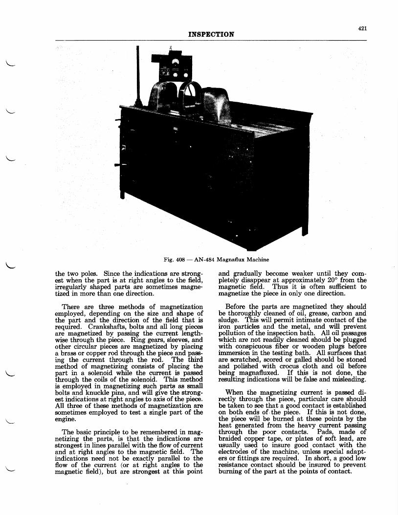
42IINSPECTION
Fig. 408 - AN-484 Magnaflux Machine
the two poles. Since the indications are strong-est when the part is at right angles to the field,irregularly shaped parts are sometimes magne-tized in more than one direction.
There are three methods of magnetizationemployed, depending on the size and shape ofthe part and the direction of the field that isrequired. Crankshafts, bolts and all long piecesare magnetized by passing the cunent length-wise through the piece. Ring gears, sleeves, andother circular pieces are magnetized by placinga brass or copper rod through the piece and pass-ing the current through the rod. The thirdmethod of magnetizing consists of placing thepart in a solenoid while the cunent is passedthrough the coils of the solenoid. This methodis employed in magnetizing such parts as mallbolts and knuckle pins, and will give the strong-est indications at right angles to axis of the piece.All three of these methods of magnetization aresometimes employed to test a single part of theenglne.
The basic principle to be remembered in mag-netizing the parts, is that the indications arestrongest in lines parallel with the flow of cunentand at right angles to the magnetic field. Theindications need not be exactly parallel to theflow of the current (or at right angles to themagnetic field), but are strongest at this point
and gradually become weaker until they com-pletely disappear at approximately 20o from themagnetic field. Thus it is often sufficient tomagnetize the piece in only one direction.
Before the parts are magnetized they shouldbe thoroughly cleaned of oil, grease, carbon andsludge. This will permit intimate contact of theiron particles and the metal, and will preventpollution of the inspection bath. All oil passageswhich are not readily cleaned should be pluggedwith conspicuous fiber or wooden plugs beforeimmersion in the testing bath. All surfaces thatare scratched, scored or galled should be stonedand polished with crocus cloth and oil beforebeing magnafluxed. If this is not done, theresulting indications will be false and misleading.
When the magnetizrng current is passed di-rectly through the piece, particular care shouldbe taken to see that a good contact is establishedon both ends of the piece. If this is not done,the piece will be burned at these points by theheat generated from the heavy curent passingthrough the poor contacts. Pads, made ofbraided copper tape, or plates of soft lead, areusually used to insure good contact with theelectrodes of the machine, unless special adapt-ers or fittings are required. In short, a good lowresistance contact should be insured to preventburning of the part at the points of contact.
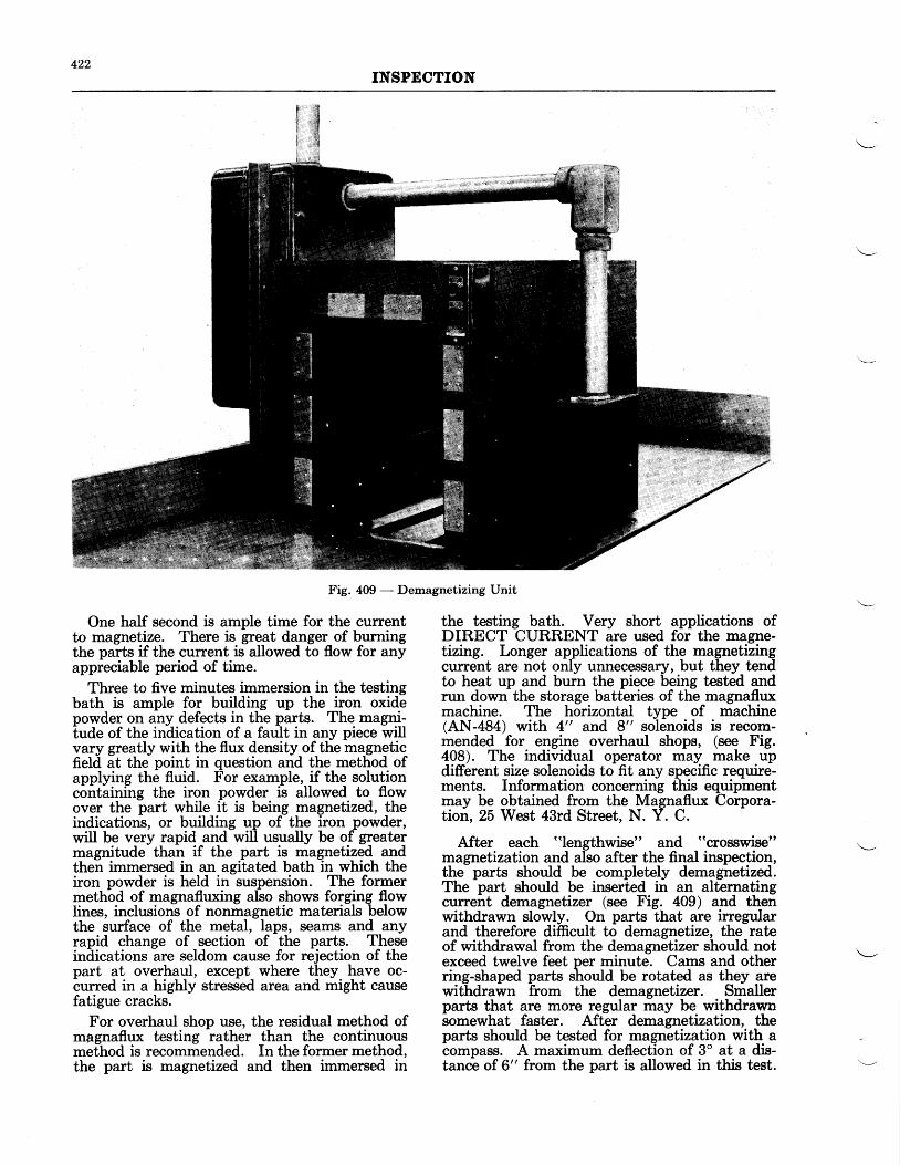
422INSPECTION
Fig. 409 - Demagnetizing Unit
One half second is ample time for the currentto magnetize. There is great danger of burningthe parts if the current is allowed to flow for anyappreciable period of time.
Three to five minutes immersion in the testingbath is ample for building up the iron oxidepowder on any defects in the parts. The magni-tude of the indication of a fault in any piece willvary greatly with the flux density of the magneticfield at the point in question and the method ofapplying the fluid. For example, if the solutionc6ntii"iirg the iron powder i-s allowed to flowover the part while it is being magnetized, theindications, or building up of the iron powder,will be very rapid and will usually be of greatermagnitude than if the part is magnetized andthen immersed in an agitated bath in which theiron powder is held in suspension. The formermethod of magnafluxing also shows forging flowlines, inclusions of nonmagnetic materials belowthe surface of the metal, laps, seams and anyrapid change of section of the parts. Theseindlications are seldom cause for rejection of thepart at overhaul, except where they have oc-curred in a highly stressed area and might causefatigue cracks.
For overhaul shop use, the residual method ofmBgnaflux testing rather than the continuousmethod is recommended. In the former method,the part is magnetized and then immersed in
the testing bath. Very short applications ofDIRECT CURRENT are used for the magne-tizing. Longer applications of the magnetizingcurrent are not only unnecessary, but they tendto heat up and burn the piece being tested andrun down the storage batteries of the magnafluxmachine. The horizontal type of machine(AN-484) with 4" and 8" solenoids is recom-mended for engine overhaul shops, (see Fig.408). The individual operator may make updifferent size solenoids to fit any specific require-ments. Information concerning this equipmentmay be obtained from the Magnaflux Corpora-tion, 25 West 43rd Street, N. Y. C.
After each "lengthwise" and "crosswise"
magnetization and also after the final inspection,the parts should be completely demagnetized.The part should be inserted in an alternatingcurrent demagnetizer (see Fig. 409) and thenwithdrawn slowly. On parts that are irregularand therefore difficult to demagnetize, the rateof withdrawal from the dema gnetizer should notexceed twelve feet per minute. Cams and otherring-shaped parts should be rotated as they arewithdrawn from the demagnetizer. Smallerparts that are more regular may be withdrawnsomewhat faster. After demagnetization, theparts should be tested for magnetization with acompass. A maximum deflection of 3" at a dis-tance of 6" from the part is allowed in this test.
423INSPDCTION
The oil passages which were plugged prior tomagnafluxing the part, should be unplugged afterinspection and the part thoroughly washed andoiled. If a part showing a slight defect is passedfor service, a complete record of the defect,showing its location and extent, should be keptso that the part may be given special attentionat the next inspection.
From the operator's point of view, the magna-flux method of inspection is of value mostly inbringing to light possible fatigue cracks whichdevelop while the part is in service. The abilityto evaluate magnaflux indications properly is toa great extent, a matter of experience and judg-ment, acquired only after extended experiencecovering various shaped parts and differenttypes of defects. For this reason, we cordiallyinvite all new operators, or new users of themagnaflux method of inspection of our engines,to send the man who will specialize in this work,to the Pratt and Whitney Aircraft factory for atraining course in this method of inspectingengine parts. In this manner, one will have theopiortunity of obtaining in a short time a varietyof-experience in the magnetizing of the various
engine parts and the interpretation and evalua-tion of the resulting magnaflux indications.
In the inspection of parts being magnafluxedattention will be given to the following generalareas where defects are most likely to occur. Onspecific parts where special attention to a partic-ular section is necessary it is noted in the Tableof Magnaflux Data which follows.
Inspect gear teeth at the roots and at the pitchline of the thrust side. Inspect splines and mat-ing lugs at the roots. Fillets and sharp angleson stressed parts should be given particularattention. Note galled or roughened areascarefully for the beginning of fatigue cracks.Steel pipes with flanges should be inspected atthe union of the flange and the pipe. Inspectbolt and shaft threads at the roots. Oil holesand shaft holes in stressed areas should be exam-ined for radial cracks emanating from the holes.
In the table which follows the term "length-
wise magnetization" will indicate that the mag-netizing current is directed along or parallel tothe major axis of the part. Likewise, "crosswise
magnetization" will indicate that current isdirected approximately 90o to the major axis.
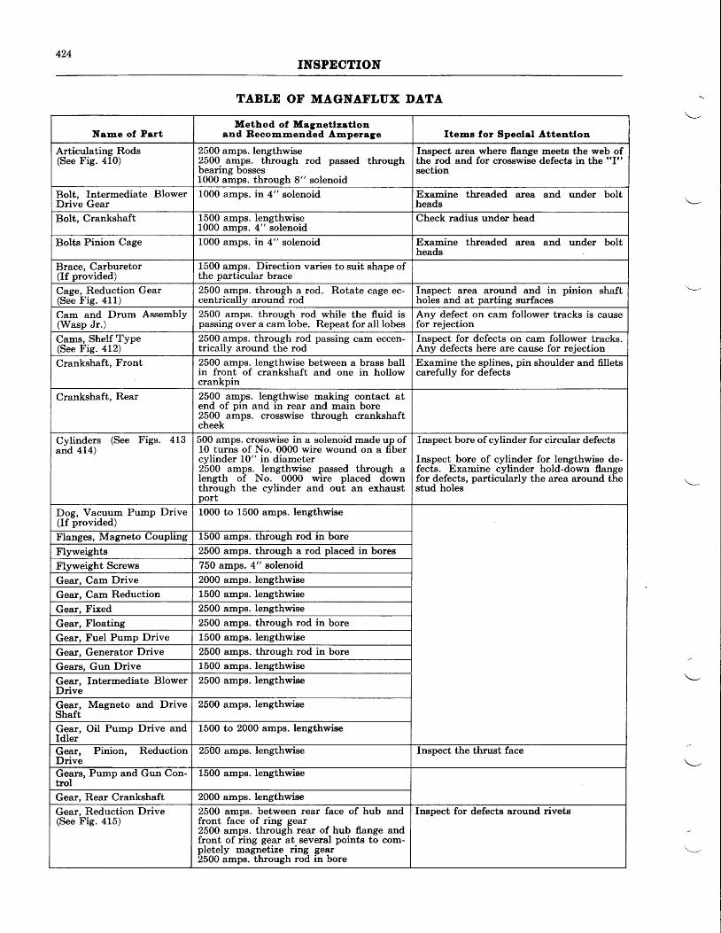
424INSPECTION
Name ol PartMethod ol Magnetlzstlon
and Reoom,mended Amperege Itens lor Speolol Attentlon
Articulating Rods(See Fig. 410)
2500 amps. lengthwise2500 amps. through rod passed throughbearing bossesL000 amps. through 8" solenoid
Inspect area where flange meets the web ofthe rod and for crosswise defects in the "I"
section
Bolt, Intermediate BlowerDrive Gear
1000 amps. in 4" solenoid Examine threaded area and under boltheads
Bolt, Crankshaft 1500 amps. lengthwise1000 amps. 4" solenoid
Check radius under head
Bolts Pinion Cage 1000 amps. in 4" solenoid Examine threaded area and under boltheads
Brace, Carburetor(If provided)
1500 amps. Direction varies to suit shape ofthe particular brace
Cage, Reduction Gear(See Fis. 411)
2500 amps. through a rod. Rotate cage ec-centrically around rod
Inspect area around and in pinion shaftholes and at parting surfaces
Cam and Drum Assembly(Wasp Jr.)
2500. amps. through-rod_while the fluid ispassing over a cam lobe. Repeat for all lobes
Any defect on cam follower tracks is causefor rejection
Cams, Shelf Type(See Fig. 412)
2500 amps. through rod passing cam eccen-trically around the rod
Inspect for defects on cam follower tracks.Any defects here are cause for rejection
Crankshaft, Front 2500 amps. lengthwise between a brass ballin front of crankshaft and one in hollowcrankpin
Examine the splines, pin shoulder and filletscarefully for defects
Crankshaft, Rear 2500 amps. lengthwise making contact atend of pin and in rear and main bore2500 amps. crosswise through crankshaftcheek
Cylinders (See Figs. 4Lgand 414)
500 amps. crosswise in a solenoid made up of10 turns of No. 0000 wire wound on a fibercylinder 10" in diameter2500 amps. Iengthwise passed through alength of No. 0000 wire placed downthrough the cylinder and out an exhaustport
Inspect bore of cylinder for circular defects
Inspect bore of cylinder for lengthwise de-fects. Examine cylinder hold-down flangefor defects, particularly the area around thestud holes
Dog, Vacuum Pump Drive(If provided)
1000 to 1500 amps. lengthwise
Flanges, Magneto Coupling 1500 amps. through rod in bore
Flyweights 2500 amps. through a rod placed in bores
Flyweight Screws 750 amps. 4" eolenoid
Gear, Cam Drive 2000 amps. lengthwise
Gear, Cam Reduction 1500 amps. Iengthwise
Gear, Fixed 2500 amps. lengthwise
Gear, Floating 2500 amps. through rod in bore
Gear, Fuel Pump Drive 1500 amps. lengthwise
Gear, Generator Drive 2500 amps. through rod in bore
Gears, Gun Drive 1500 amps. lengthwrse
Gear, Intermediate BlowerDrive
2500 amps. lengthwise
Gear, Magneto and DriveShaft
2500 amps. lengthwise
Gear, Oil Pump Drive andIdler
1500 to 2000 amps. lengthwise
Gear, Pinion, ReductionDrive
2500 amps. lengthwrse Inspect the thrust face
Gears, Pump and Gun Con-trol
1500 amps. lengthwise
Gear, Rear Crankshaft 2000 amps. lengthwise
Gear, Reduction Drive(See Fig. 415)
2500 amps. between rear face of hub andfront face of ring gear2500 amps. through rear of hub flange andfront of ring geat at several points to com-pletely magnetize ring gear2500 amps. through rod in bore
Inspect for defects around rivets
TABLE OF MAGNAFLUX DATA
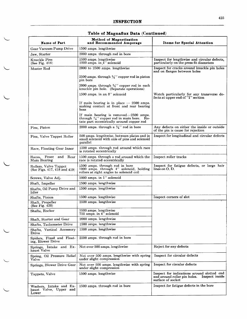
425INSPECTION
Table of Magnaflux Data (Contlnued)
Narne ol PertMethod of Magnet lzst lon
snd Reoommended Amperege trteme for Speolal Attentlon
Gear Vacuum Pump Drive 1500 amps. lengthwrse
Jaw. Starter 2000 amps. through rod in bore
Knuckle Pins(See Fig. 416)
1500 amps. lengthwise1000 amps. in,4" solenoid
Inspect for lengthwise and circular defects,particularly on the press fit diameters
Master Rod 2000 to 2500 anps. lengthwise
2500 amps. through gy'," copper rod in pistonpin bore
2000 amps. through f" copper rod in eachknuckle pin hole. (Separate operations)
1-500 amps. in an 8" solenoid
If main bearing is in place - 2500 amps.making contact at front and rear bearingboss
If main bearing is removed-2500 amps.through 11" copper rod in main bore. Ro-tate part eccentrically around copper rod
Inspect for cracks around knuckle pin holesand on flanges between holes
Watch particularly for any transverse de-fects at upper end of "I" section
Pins. Piston 2000 amps. through a 94" rod in bore Any defects on either the inside or outsideof the pin is cause for rejection
Pins, Valve Tappet Roller 500 amps. Iengthwise, between plates and insmall solenoid with axis of pins and solenoidparallel
lnspect for longitudinal and circular defects
Race, Floating Gear Inner 1500 amps. through rod around which raceis rotated eccentricallv
Races, Front and RearMain Bearing
1500 amps. through a rod around which therace is rotated eccentricallv
Inspect roller tracks
Rollers, Valve Tappet(See Figs. 4L7, 4L8 and 419)
1500 amps. through rod in bore1000 amps. through 4" solenoid, holdingrollers at right angles to solenoid coil
Inspect for fatigue defects, or large hairlines on O. D.
Screws, Valve Adj. 1000 amps. in l" solenoid
Shaft, Impeller 1500 amps. lengthwrse
Shafts, Oil PumP Drive andIdler
1500 amps. lengthwrse
Shafts, Pinion 1500 amps. lengthwise Inspect corners of slot
Shaft, ProPeller(See Fig. 420)
2500 amps. lengthwrse
Shafts, Rocker 1500 amps. lengthwise750 amps. itt 4" solenoid
Shaft, Starter and Gear 2000 amps. lengthwrse
Shafts, Tachometer Drive 1500 amps. Iengthwise
Shafts, Vertical AccessorYDrive
1500 amps. lengthwrse
Spiders, Fixed and Float-ing, Blower Drive
2500 amps. through rod in bore
Springs, Intake and Ex-haust Valve
Not over 500 amps.lengthwise Reject for any defects
Spring, OiI Pressure ReliefValve
Not over 500 amps. lengthwise with springunder slight compression
Inspect for circular defects
Springs, Blower Drive Gear Not over 500 amps. lengthwise with springunder slight compression
Inspect for circular defects
Tappets, Valve 1-500 amps. Iengthwise Inspect for indications around slotted endand around roller pin holes. Inspect insidesurface of socket
Washers, Intake and Ex-haust Valve, Upper andLower
1500 amps. through rod in bore Inspect for fatigue defects in the bore
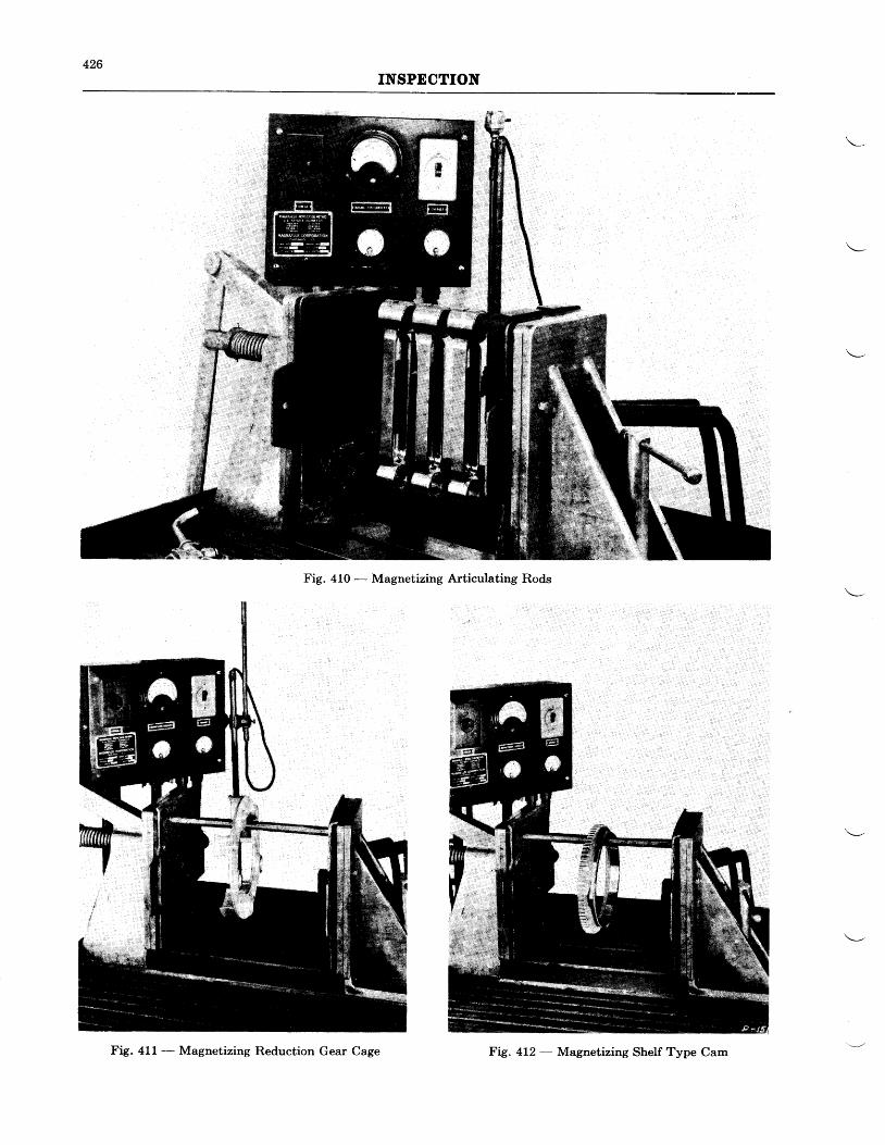
426INSPECTION
Fig. 410 - Magnetizing Articulating Rods
Fig. 411 - Magnetizing Reduction Gear Cage Fig. 412 - Magnetizing Shelf Type Cam
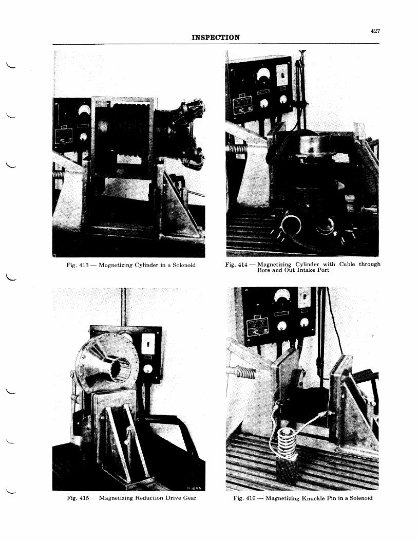
427INSPECTION
Fig. 413 - Magnetizing Cylinder in a Solenoid Fig. 414 - Magnetizing Cylinder with Cable throughBore and Out Intake Port
Fig. 415 - Magnetizing Reduction Drive Gear Fig. 416 - Magnetizing Knuckle Pin in a Solenoid
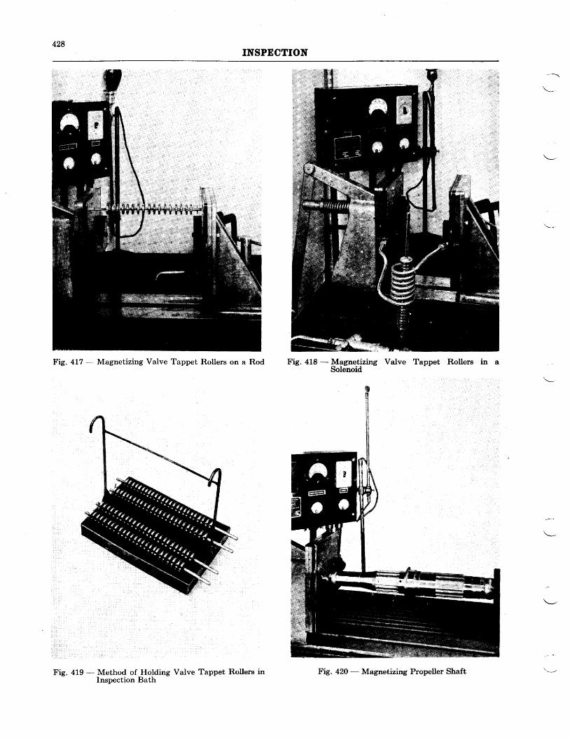
428INSPECTION
Fig. 4L7 - Magnetizing Valve Tappet Rollers on a Rod Fig. 418 - Magnetizing Valve Tappet Rollers in aSolenoid
Fig. 419 - Method of Holding Valve Tappet Rollers inInspection Bath
Fig. 420 - Magnetizing Propeller Shaft
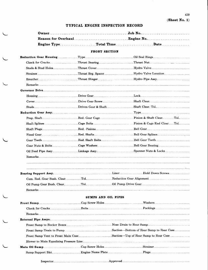
429
(Sheet No. l)
TYPICAL ENGINE INSPECTION RECORI)
\-,
Owner
Reason for Overhaul. . .
Englne Type . . . Total Tlme. .
FRONT SDCTION
.... . . . .Thrust Bearing.
. . . . . , .Thrust Cover . . . . .
. . . . . . . .Thrust Brg. Spacer . . . . . . . . . .
. . . . . . . .Thrust Sl inger.. .
. . . .Red. Gear Cage
. . Job No..
. . Englne No.
. . I)ate. .
Hydro VaIve. . . . . . . .
. . . . Hydro Valve Location... . . . . . . . .
SUMPS AND OIL PIPES
, . . . . . . . . . . . . . . .Cap Sc rew Ho les . . . . . . . . . . . . . .
E r t e rna l P lpe Assys . . . . . . . . . . . . . . . .
Front Sump to Rocker Boxes........
Front Sump Dra in to Pump. . . . . . . ; . . . . . .
Front Sump Vent to Front Main Case... . . . . . . .
Reduction Gear Alignment..........
Oi l Pump Dr ive Gear . . . . . . . . .
..Washers..
..Packings.
Inspector.. . . . . . . . . .Approved. . . . . .
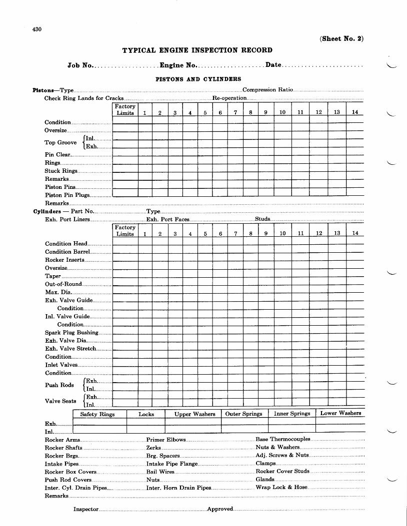
430
TYPICAL ENGINE INSPECTION RECORI)
.I)ate
(Sheet No. 2)
Job No.. . .
Condi t ion Head. . . . . . . . . . . . . . . . .
Condit ion BarreI.. . . . . . . . . . . . . .
Rocker Inserts......
Oversize...
Taper
Out-of-Round... . . . . . . . . .
Max. Dia . . . . . . . . . . . .
Exh. Valve Guide....
Condition
In l . Va lve Guide. . . . . . . . . . . . . . .
Condition
Spark Plug Bushing..,......
Exh. Valve Dia... . . . . . . . . . . . . . . .
Exh. Valve Stretch...........
Condition
In le t VaIves. . . . . . . . . . . . . . . . . . . . . . .
Condition
D,-^L D^,r- Ie*" 'r r r D ' r t v s D
1 r t 1 . . . . . . . . . . . .
- f nxh. . . . . . . . . .Va lveSea ts { - .
I I n l ' " " " " '
Exh... . . . . . . .
In I . . . . . . . . . . . . . .
Rocker Arms... . . . . .
Rocker Shafts.......
Rocker Brgs... . . . .
Intake Pipes... . . . . . .
Rocker Box Covers... . . . . . . . .
. Englne No..
PISTOITS ANI} CYLINI'ERS
..Compression Ratio....
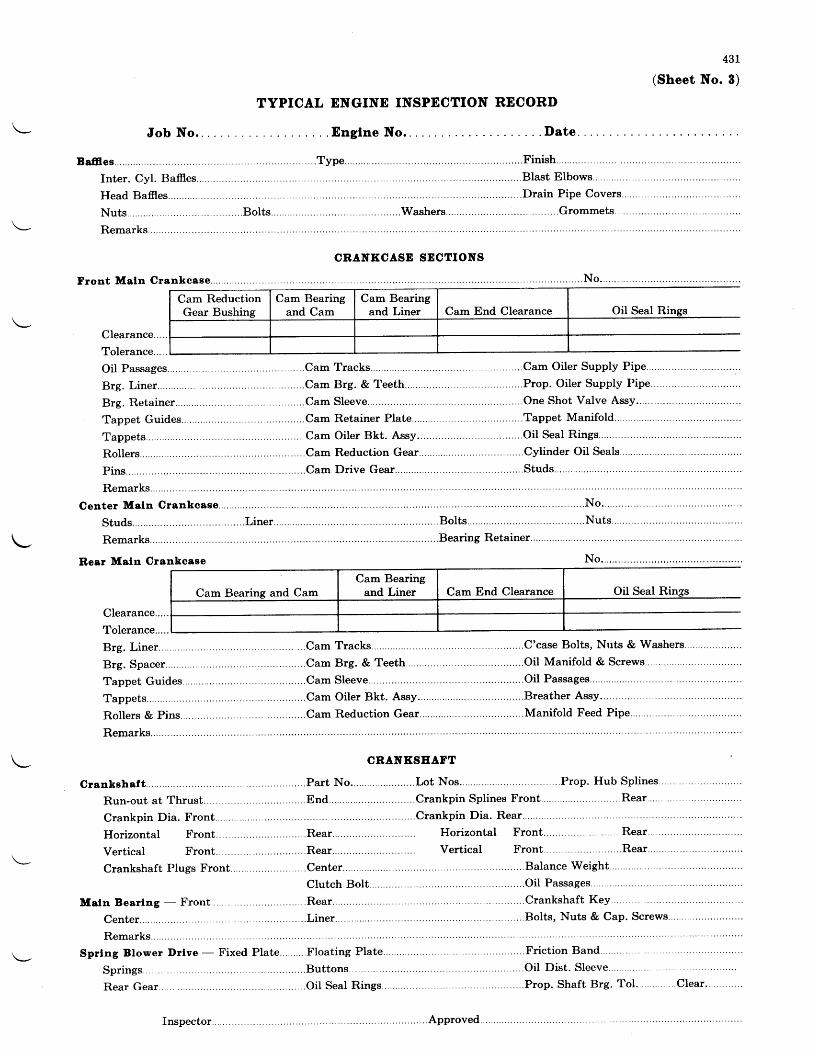
431
8)
Job No.
Bnff iee. . . . . .
I n te r . Cy l . Ba f res . . . . . . . . . . . . . . .
Head Bafres. . . . . . .
TYPICAL ENGINE INSPECTION RECORD
. Englne No..
. . . . . . . . .Type
. . . . . . ; . "hers . . . . . . . . . .
B last E lbows. . . . . . . . . . . . .
. . . . . . .Drain Pipe Covers
.Grommets...
(Sheet No.
CRANKCASE SDCTIONS
Clearance...
Tolerance...
Remarks..
Rear Meln Crankoase
Oil Seal Ri
.. . .Cam Oiler Supply Pipe... . . .
. . . . .Prop. Oiler Supply Pipe... . .
. . . . . . . . . . . . . .One Sho t Va l ve Assy . . . . .
, . . . . . . . T .ppe t Man i f o l d . . . . . . . . . . . . . . . .
N o . . . . . . . . . . . . .
.Nu ts . . . . . . . . . .
Oil Seal
. . . . . . . .Cam Tracks. . . . . . . . . . . . . . . .C 'case Bol ts , Nuts & Washers
... . . . .Cam Brg. & Teeth... . . . . . . . . . .OiI Manifold & Screws..
Tappet Guides. . . . . . . . . . . .Cam Sleeve. . . . . .
Tappets... .
Rol lers & Pins... . . . .
Remarks..
.Cam Oiler Bkt.
.Cam Reduction
Grankshe f t . . . . . . . . . . . . . . .
Run-out at Thrust.. . . .
Crankpin Dia. Front..
Horizontal Front.
. . .End... . . . . . . . . .Crankpin Splines Front.
Horizontal Front. . . . . .Rear.. . . . .
Ver t ica l Front . . . . . . . . . .Rear . . . . . . .
.Balance Weight.. . . .
. . . . .OiI Passages...
. . . .Crankshaft Key... .
. . . . . . . . . .BoIts, Nuts & Cap. Screws.
Vertical
Crankshaft Plugs Front
Meln Bear lng - Front . . . . . .
Center. . . . . .
Remarks..
Sprlng Blower Drlve - Fixed
Springs
Rear Gear
Cam End ClearanceCam ReductionGear Bushing
Cam End ClearanceCam Bearing and CamCam Bearing
and Liner
Inspector
. . .C lea r . . . .
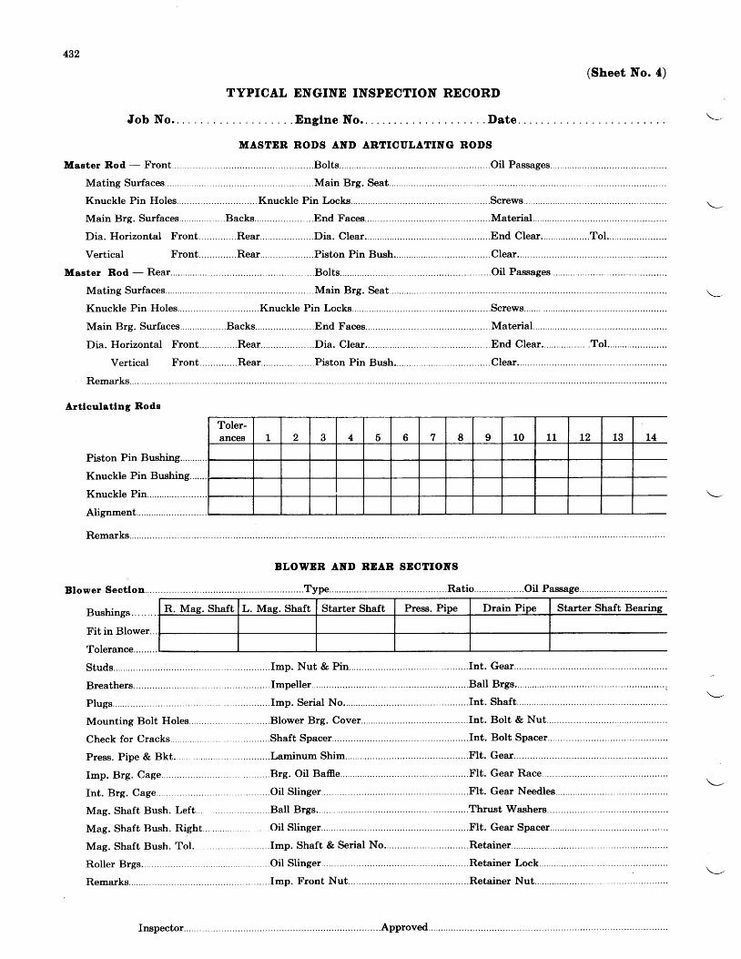
432
Blower
(Sheet No. 4)
Job No. . . .
Knuckle Pin Holes .. . . . . . . . . . .Knuckle
Main Brg. Sur faces. . . . . . . . . . . . . . . . . .Backs. . . . . . . . .
Vertical
Knuckle Pin Holes
Main Brg. Sur faces. . . . . . . . . . . . . . . . . .Backs. . . . .
TYPICAL ENGINE INSPECTION RECORI)
MASTDR AND ARTICULATING
BLOWDR AND BDAB SDCTIOITS
Plugs. . . . . . . . .
Mounting Bolt Holes... . . . . .
Check for Cracks
Press. Pipe & Bkt.. . . . . .
Imp. Brg. Cage. . . . . . .
In t . Brg. Cage. . . . . . . . .
Mag. Shaft Bush. Left....
Mag. Shaft Bush. Rieht.. . . . . . . .
Mag. Shaft Bush. Tol.. . .
Rol ler Brgs... . . . . . .
Remarks..
Laminum Shim... . . . . . . .
Brg. Oil Baff ie.. . . . . . .
. . .Oi l Sl inger.. . . . .
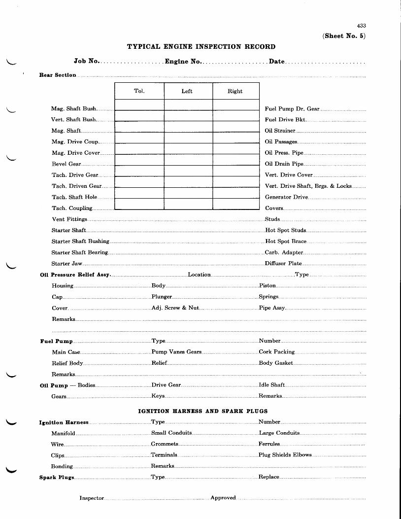
433
(Sheet No. 5)
TYPICAL ENGINE INSPECTION RECORI)
J o b N o . . . . .
Rear Sectlon...
Date.
\-Assy . . , . . . . . . .olr
\-,
\- Ignltlon Eornees..
Nut . . . . . . . . . . .
Drive Gear.. . . . . .
Manifold
Wire. . . . . . . . . .
Spork P lugs. . . . . . . .
EARNDSS AND SPARK PLI'GS
\-
Inspector...

434
Job No.. . .
Rtght MagnetoHousing...
Rota. Magnet....Dist. Finger Cyl.... ..
Brkr. Contact Screws......
Coupling..Ground Screw... . . . .
Remarks..
(Sheet No. 0)
TYPICAL ENGINE INSPECTION RECORD
. Englne No.. . Date
ACCESSOBIES
..Number.
. . . . . . . . . . .D is t . B locks. . . . . . . .
. . . . . . . . . . . . .Ca rbon B rush . . . . . . . . . . . . . . .
M a i n B o d y C a s e s . . . . . . ' ' . . . . . . . . . . B o d y S c r e w s � � � � � � � � � � � � � � � � � � � � � � � � � � � � � � � � � � � � � � � � � � � � � � � � � � � � � � � � � � � � � � � � � � � � � � � � � � � � � � � � � � � � � � � � � �
OII Temp. Control - Bodies .. .Thermostat.. . . . . . . . . . . . . . .Va1ve... . .
Set . Number . . . . . . . . . . . . . . . . . . . . . . . . . . . .Mid-pos i t ion Press. . . . . . . . . . . . . . . . . . . . . .Cru is ing Press. . . . . . . . . . . . . . . . . . . . . .
Needle Valve Sylphons.. .......Needle Valves... .........Range Shifter...
Press Cont . Va lve. . . . . . . . . . . . . . . . . .Cont . Va lve Levers . . . . . . . . . . . . . . . . . . . .Nuts and Washers. . . . . . . . . . .
Gaskets.. . . . . . .tltorter....
Ser ies . . . . . . . . . . . .Plan. Gear..Fly Wheel..Bevel Pinions... . . . . .Bel l Gear.. . . . . . . . .
Remarks..Stor ter Motor . . . . . .
Housing...Brushes....Field Coils.. . . . . . . . .Terminal Shield.. . . . . . . . . .
Solenold Swltch... . .Housing...Terminal Nuts... . . . . . . . . . .Shielding.
Meshlng Solenold.
Housing..Coi l Term. Nut . . . . . . . . .Shielding.

Job No. . .
Booster Col l . . . . . . . . . . .
Housing...
Contact Screw. . . . . . . . . . .
TYPICAL ENGIND INSPECTION
. Englne No..
Model . . . . . . .
RECORI). . Date
435
(Sheet No. 7)
Remarks..
Gene ra to r . . . . . . . . . . . . . .
Armature
Brushes....
Reverse Cur. Cutout.. . . . . . . . . . . . . .
Resis. Units.. . . . . . .
Remarks..
Sh lpp lng Par ts . , . . . . . .
Hub Attach. Parts..
Primer Lines... . . . . . .
Spark P lug Hole P lugs. . . . . . . . . . . . . . . . . .
Remarks,.
Inspector.. . . .
..Sp". Dampeners...
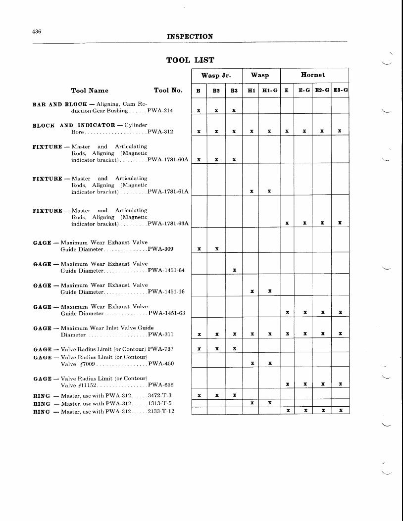
436INSPECTION
TOOL LIST
Tool Narne Tool No.
BAR AND BLOCK - A l ign ing, Oam Re-duction Gear Bushing. . . . . .PWA-214
BLOCK AND INDICATOR - CYl inderBore. PWA-312
FIXTURE - Master and ArticulatingIl.ods, Aligning (Magnetici nd i ca to rb racke t ) . . . .PWA-1781 -60A
FIXTURE - l\faster and ArticulatingItods, Aligning (Magnetici nd i ca to rb rac l<e t ) . . . .PWA-1781 -61A
FIXTURD - Master and ArticulatingRods, Aligning (Magneticindicator bracket) . . . .PWA-1781-63A
GAGE - Maximum Wear Exhaust ValveGuide Diameter . . . .PWA-309
GAGD - Maximum Wear Exhaust ValveGuide Diameter . . . .PWA-7451-64
GAGE - Maximum Wear Exhaust ValveGuideDiameter . . .PWA-1451-16
GAGE - Maximum Wear Exhaust ValveGu ide D iame te r . . . .PWA-1451 -63
GAGE - Maximum Wear Inlet Valve GuideD i a m e t e r . . . . P W A - 3 1 1
GAGE - Valve Radius Limit (or Contour) PWA-737
GAGE - Valve Iladius Limit (or Contour)Valve #7009 . .PWA-450
GAGE - Valve Raclius Limit (or Contour)Valve #11L52 . .PWA-656
RING - Master, use with PWA-312 3472-T-3
RING - Master , use wi th PWA-312. . . . .1313-T-5
RING - Master, use with PWA-312 2133-T-12
Wasp Jr. Wasp Hornet
B B2 B8 E1 ET- G E E.G 82. G 83. G
x x x
x x x x x x x x x
x x x
x x
x x x x
x x
x
x x
x x x x
x x x x x x x x x
x x x
x x
x x x x
x x xx x
x x x x
501
CEAPTER V
REPAIR AND ASSEMBLY OF MAJOR SUB-ASSEMBLIES
REPAIR
General-In this chapter the method of repairingor replacing engine palts is described. Certainrep"ii instrlctio-ns, c6rrlron to a number of similartype parts, are contained in the subsequent para-graphs of this "General" section and will not berepeated under the detail repair instructions.
Ilouslngs, Cover Plates, Crankcase Sectlons,Etc.-Burrs or mutilations which do not tend toincrease in size or in any way impair the servicea-bility of the part should be smoothed over or re-moved. Excessive flaking, chipping or scratch-ing of paint should be cause for completely re-painting the part.
Studs-Studs which are loose or have mutilatedthreads should be replaced by oversize studs.Whenever a stud which is already oversize re-quires replacement, it should be replaced by thenext oversize. Consult the parts list for availa-ble sizes. Where the threads of a stud hole havebecome damaged or stripped out it is possible todrill and retap the hole for a special stepped studif tltere is sufficient material around the hole.It is also sometimes possible to install a bronzebushing in such cases. The Pratt and WhitneyAircraft Service Department should be consultedif this is contemplated.
Rlvets-All loose rivets which are found at in-spection should be replac6d, or tightened if feasi-ble.Bearlng Surfaces and Bushlngs-Bearing sur-faces and bushings should be polished with crocuscloth and oil if scratched or scored. A fine stonemay be used on steel bearing surfaces if polishingwith crocus cloth is not sufficient to make themsmooth. Unless scratched or scored the glazedsurfaces of bushings should not be disturbed.
Plating-At overhaul it is common practice toplate certain engine parts to prevent galling, cor-rosion or picking up of the metal.
During the plating operation, stresses are setup in the metal, causing embrittlement, whichmay cause cracks and subsequent failure if notcorrected. It is believed that the embrittlementis due to the absorption of hydrogen by the metalduring plating operations. The harder the metalbeing plated and the thirrner its section, thegreater the embrittlement.
To relieve this condition, it is recommendedthat, immediately after any kind of plating,highly stressed parts, in particular, be baked forone hour at a temperature of 275" F. -- 300' F.(135' C.-149" C.). Iffacilitiesfor baking are notavailable, the parts may be placed in actively
boiling water for approximately three hours.Springs or other articles subject to flexure, shouldnot be flexed prior to the baking operation.
In cases where plating work is sent to a com-mercial plating concern, these precautions shouldbe emphasized.
Expanslon of Parts by Heat-In many in-stances, the removal of liners and bushings re-quires that heat be applied to the metal surround-ing the part to be removed. The method ofplacing the part in a heated oven and graduallybringing the entire area up to the required tem-perature is the safest and the least likely to causewarping. The heating of the parts with a torchis the most universally practiced method, and issatisfactory providing sufficient care is exercisedin its use. A soft flame gas torch should be used,and care taken not to allow the flame to concen-trate too long on one spot. The flame should beplayed over the entire area surrounding the partto be removed. Because of the nature of magne-sium, the application of a torch to this metal re-quires .the utmost care. The immersion ofmagnesium parts in actively boiling water willexpand them sufficiently for the removal of liners,without the attendant danger of warping occa-sioned by the use of a torch. The amount ofheating that is necessary for the removal of linersis largely a matter of judgment and experience.If magnesium parts are kept below 250o F.(LzL" C.) and if aluminum parts are kept below300o F. (149" C.), the danger point will not bereached.
Chrornlc Acld Treatrnent - The chromic acidtreatment is an anti-corrosion treatment appliedto magnesium base alloys. At overhaul it issometimes desirable to thus treat magnesiumparts which contain indications of corrosion oron which the original pickling treatment is nolonger effective. A steel tank large enough topermit submersion of any part which is to betreated is required. The procedure for strippingand cleaning the parts is as follows:
Degrease the parts in a vapor degreaser or inkerosene. Remove the paint as described in theparagraph entitled "Painting", and immerse theparts for approximately five minutes in a boilingchromic acid solution (100' C. - 212" F.) of thefollowing composition:
Chromic Acid (Cr0r)Water
1.5 lbs.to make 1.0 gal.
If tap water is used, .lo/o silver nitrate (AgNOs)should be used to precipitate soluble chlorides.
502REPAIR AND ASSEMBLY OF MAJOR SUB-ASSEMBLIES
Dissolve the silver nitrate in distilled water andadd it to the chromic acid bath.
Remove the parts and rinse thoroughly infresh cold running water and then in hot water.Dry with compressed air. Apply the primerand paint as described under "Painting".
Palnting-Before repainting parts at overhaul,their surfaces must be properly prepared to re-ceive the paint. If it is desired to remove theoriginal finish, any one of three methods of strip-ping may be used. The first, dipping the paintedparts in a heated stripping solution, is the mosteffective. Solutions such as the No. 70 Stripperof the E. A. Gerlach Co., 3567 Sepviva St.,Philadelphia, Pa., are satisfactory for use in thefirst method. The second method involvesbrushing a heavy coat of a paint removing sub-stance on the paint and then wiping the old pqintfrom the metal. "Wonder-Paste" manufac-tured by the Wilson-Imperial Co., Newark, N. J.,is one of the satisfactory products for use in thismethod. The third method involves removalof the paint with a stiff wire brush. When thismethoil is used with magnesium parts, it is de-sirable to retreat them \{rith the Chromic AcidTreatment.
If the old paint is not to be removed, the sur-face should be smoothed up with emery or crocuscloth. Cylinder heads should have all the re-maining old paint removed by sandblasting priorto repiinting to prevent building-up of the oldcoats and impairment of cooling efficiency. R€-fer to Chapter III for instructions on sandblast-ing cylinders.
Prior to printing, all surfaces should be de-greased as described in Chapter III "Cleaning".
Holes should be plugged with corks, and areasand perts not to be painted should be coveredwith suitable masks or masking paper. The fol-lowing list gives the type of paint, number ofcoats to be applied, the length of time for bakingand the baking heats to be used. Paints may beapplied with an atomizer or a brush; they maybe baked or air-dried.
Magneslurn Parts(A) 1 coat zinc chromate primer(B) 3 coats gray enamel or(C) 3 coats black enamel
Alurnlnurn Alloy Parts (Ereept CylinderIfeads)
(A) 1 coat zinc chromate primer(B) 2 coats gray enamel orrc) 2 coats black enamel
Baklng Tlme for Above Palnts(A) l lhow at250'F. (121 'C.)(B) 1 )4 holulrs at 275" F. (135" C.)(C) 1)4 hours at 275" F. (135' C.)
Alurnlnurn Alloy lleads and Steel Barrels
2 coats black high-bake enamel and bake3 hours at 425" F. (218' C.)
The following makes of finishes are satisfactoryfor use:
Zinc Chromate Primer PWA Spec. 219 manu-factured by the Egyptian Lacquer Co., l27ASixth Ave., N. Y. C.
Gray Aircraft Engine Enqme! PWA Spec.- 146muttrrfactured by the Egyptian Lacquer Co., 1270Sixth Ave., N. Y. C.
Black Aircraft Engine Enamel, PWA SP*'803-A manufactured bV Pratt & Lambert Co',Buffalo, New York.
Black Aircraft Engine Cylinder Enamel (BWASpec. 226-A) V-1183, manufactured by the LoweBros. Co., Dayton, Ohio.
All surfaces contacting flat gaskets should bepainted with one coat each of zinc chromateprimer and enamel.
Aluminum alloy and steel mating surfacesshould be left unpainted.
Magnesium alloy mating, surfaces should bepainte? with one coat each of zinc chromateprimer and enamel.
Metallized Cylinders-It is not anticipatedthat frequent iesurfacing of aluminu-m sprayedcvlinders will be necessiry, although this willd"epend largely upon conditions o-f operation andth6 kind of tr-eatinent to which the cylinders aresubjected (as well as upo-n the -quality of themetallizing' job). Norm^ally, it shbuld be suffi-cient to clean cylinders in a regular engine-partscleaning bath a[ overhaul, and respraying shouldnot be necessary for at least two or three over-hauls. When resurfacing becomes necessary' orif it is desired to metalliZe cylinders which werepreviously enameled, this may be accomplishedas follows:
Thoroughly degrease, sandblast, qld clean theexternal frrrfaceJ as described in Chapter III'The old aluminum finish need not be entirelyremoved, the well bonded portions making qsatisfactory base for a new coat. Where enamelwas previously used, however, all traces of theettatttlel must be removed. After cylinders havebeen cleaned and sandblasted, do not touchwlth bare hands a surface whlch ls to bernetal sprayed.
Cover all studs and openings. (Old parts suchas metal plates, rubber
-stoppers, rubber hose and
copper tribing are often useful-for this purpose.)Olh rocker Jovers, held in place by pieces ofcopper tubing inserted over ?nd ^pinched tighton ttte studs, are recommended for p-rotectin-gthe inside of ihe rocker boxes. Discarded spark
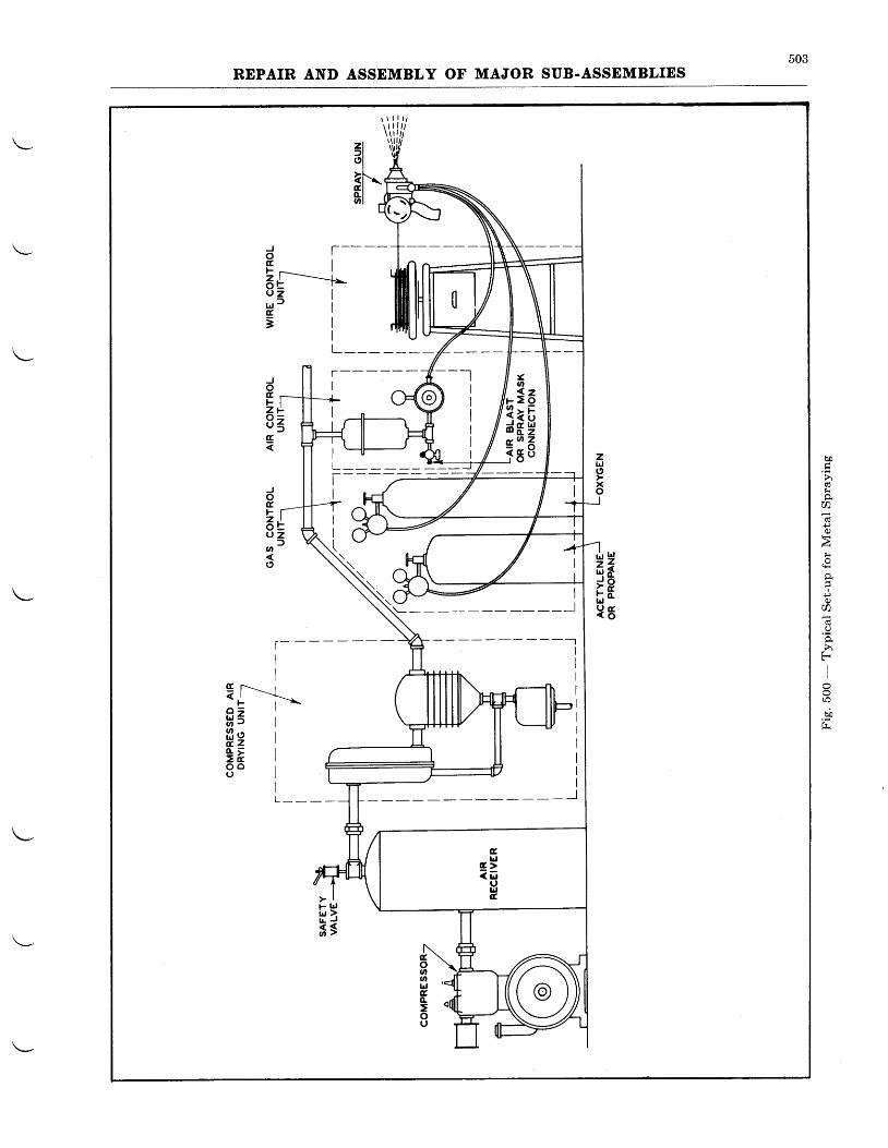
503REPAIR AND ASSEMBLY OF MAJOR SUB.ASSEMBLIES
J T -o tF I
aE----*Q z Iu J fg3
tdzldJ
FbJu
lrj2a<oa,o.tro
tl-**o - |fr=frzi t8 "
> lF lrjtrt )I L J
f stroananldc,o.=oU
Gtd
c >< L '
utdt
boi
h
}r
a6€
li
I
+)Q)
0
f)
ll
ro
bi
504REPAIR AND ASSEMBLY OF MAJOR SUB-ASSEMBLIES
plugs and gaskets ryay_ be used to proteq_t thethreaded inserts. The lower side of the cylindermounting flange and the skirt of the barrelshould be protected by a sleeve made high andwide enough to hold the assembly firmly.
The booth in which the cylinders are to besprayed should be equipped with an exhaust fanto diaw off fumes, etc., and should have a smallturntable on which the parts may be rotated.'fhis turntable may be power driven if desired.If the table is rotated by hand, an asbestos mittenmust be worn to protect the operator from theflame of the spray torch. Rocker box coversshould be held flat while being sprayed.
Cautlon-It is important that the operatorwear a respirator and goggles while sandblast-ing and metal spraying.
The spray gun should be held approxim4telysix inchei from the work and at an angle of about15' - 20' to the surface in both directions,so that the area between the fins is effectivelycoated. Apply a final coat holding the gun atright angles to the surface to insure a goo_d ggat-ing on the edges of the fins. The desired thick-neis is .003" and the maximum thickness shouldnot exceed .005". Excessively thick coatingtends to produce a rough finish and has a ten-dency to flake off. After spraying, inspect thefinish for uniformity and quantity.
When cylinders are to be stored after spraying,they should be completely coated with No-OxideEEE, which may be obtained from DearbornChemical Company, New York City, N. Y.,or some other similar corrosion preventing com-pound.
Assuming that compressed air (35 cu. ft, offree air per minute at 80 p.s.i.) and sandblast
equipment is available, the following equipmentis recommended:
Type E Metco Metallizing Unit complete with:1 _ 11 B & S and rf,, Wire Nozzles1 - 1 1 B & S a n d f t " A i r c a p s1 - Lathe Fixture1 - Tube Valve Lubricant1 - Tube Gear Case Lubricant1 - Complete set of Tools1 - Instruction Manual
Type 2H Gas, Oxygen, and Air Hose UnitType A Metco Air Control UnitType 25 Metco Wire Control UnitNo. G-10 Metco Oxygen RegulatorNo. 2G-X40A Gas RegulatorType W Metco Compressed Air Drying Unit-No.
554A, complete with expeller and after-cooler
Wilmington - Metco Type SH23 City GasCompressor complete with Yz H.P., L20-220Volt, single phase, 50-60 cycle, dust proof motor,gas tankrpressure switch, and flash back arrestor.
Note-All of the above material is obtainablefrom:Metallizing Engineering Company, Inc.2107 41st AvenueLong Island City, New York
Note-If it is desired to use Propane, Hydro-gen, or Acetylene Gas (in bottled form)in place of city gas, the gas compressorrs unnecessary.
Fig. 500 shows schematically a typical metalspray equipment set-up.
DETAIL INSTRUCTIONS
FRONT (Nose) SECTION-WASP JR.
Thrust Bearlng Llner-If for any reason itis neaessary to replace a liner in the front sec-tion, the area adjacent to the liner should beheated to a temperature of 200" F.-250' F.(93' C.-121" C.) (see Page 501) and then theliner should be drifted out of the nose.
In order to reinstall the new liner, the frontsection should be reheated to the same tempera-ture and the new liner inserted in position.This operation will be facilitated by chilling theliner with dry ice (COz) prior to installation inthe front section. Care should be taken to seethat the oil holes in the new liner are in align-ment with the oil holes in the front section andthat the liner is bottomed properly. This lattercondition should be checked by attempting to
insert a .001" feeler gage between the liner andthe case. If it is not possible to insert this gageat any point, the liner may be judged to havebottomed properly.
After a new liner is installed, the thrust bear-ing seating surface and the propeller_oil--transferriig seatiig surface should be ground. Where itis necessary to grind the bore of a liner to accom-modate oversize oil transfer rings, the same in-structions apply as for a standard bore with theonly difference being in the size to which theIiner is ground. To accomplish the grilding,the front section should be bolted to an adapterplate mounted in a lathe. Using a dial indicator,indicate the nose section so that the liner for-ward face and bore are turning concentrically
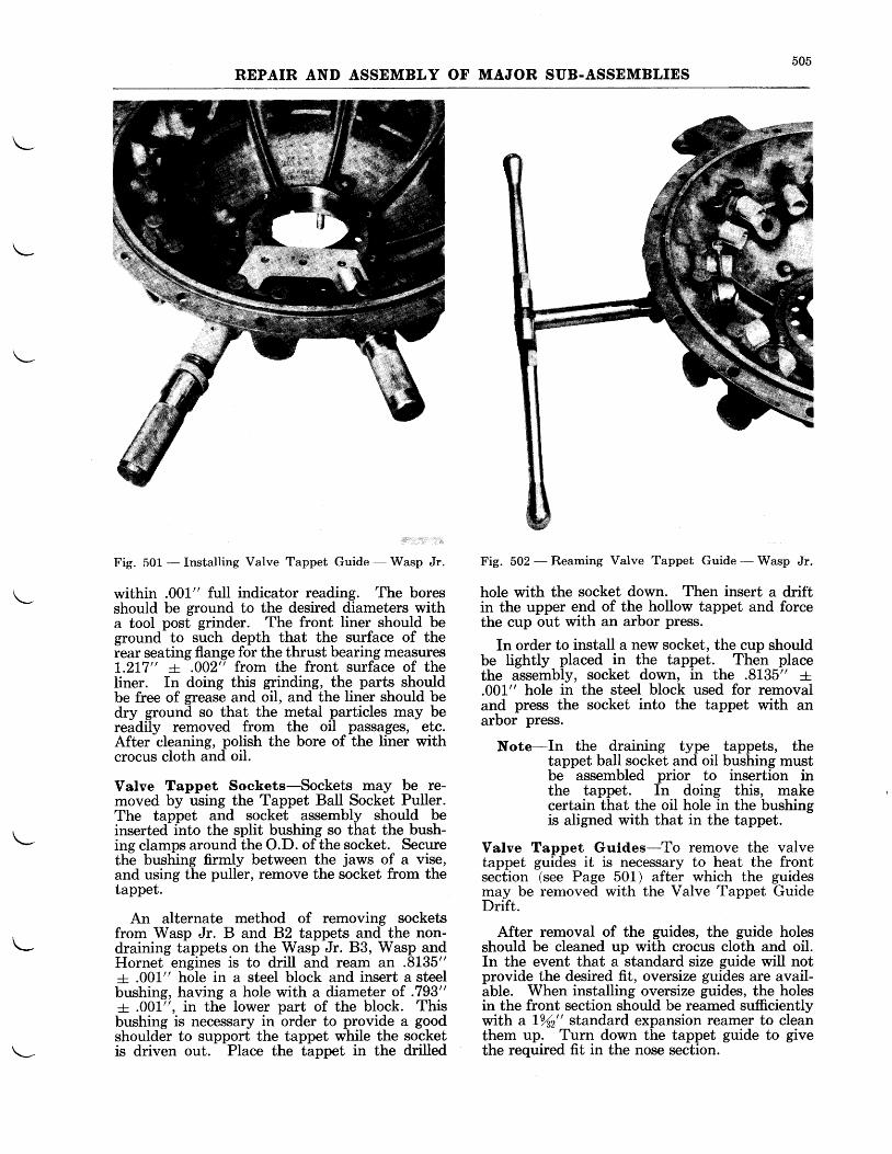
505REPAIR AND ASSEMBLY OF MAJOR SUB.ASSEMBLIES
Fig. 501 - Installing Valve Tappet Guide - Wasp Jr.
within .001" full indicator reading. 'fhe boresshould be ground to the desired diameters witha tool post grinder. The front liner should beground to such depth that the surface of theiear seating flange for the thrust bearing measures!.2I7" + .002" from the front surface of theliner. In doing this grinding, the parts shouldbe free of grease and oil, and the liner should bedry ground so that the metal particles may bereadily removed from the oil passages, ete.After cleaning, polish the bore of the liner withcrocus cloth and oil.
Valve Tappet Sockets-Sockets may be re-moved by using the Tappet Ball Socket Puller.The tappet and socket assembly should beinserted into the split bushing so that the bush-ing clamps around the O.D. of the socket. Securethe bushing firmly between the jaws of a vise,and using the puller, remove the socket from thetappet.
An alternate method of removing socketsfrom Wasp Jr. B and 82 tappets and the non-draining tappets on the Wasp Jr. 83, Wasp andHornet engines is to drill and ream an .8L35"+ .001" hole in a steel block and insert a steelbushing, having a hole with a diameter of .793"+ .001", in the lower part of the block. Thisbushing is necessary in order to provide a goodshoulder to support the tappet while the socketis driven out. Place the tappet in the drilled
Fig. 502 - Reaming Valve Tappet Guide - Wasp Jr.
hole with the socket down. Then insert a driftin the upper end of the hollow tappet and forcethe cup out with an arbor press.
In order to install a new socket, the cup shouldbe lightly placed in the tappet. Then placethe assembly, socket down, in the .8135" r.001" hole in the steel block used for removaland press the socket into the tappet with anarbor press.
Note-In the draining type tappets, thetappet ball socket and oil bushing mustbe assembled prior to insertion inthe tappet. In doing this, makecertain that the oil hole in the bushingis aligned with that in the tappet.
Valve Tappet Guldes-To remove the valvetappet guides it is necessary to heat the frontsection (see Page 501) after which the guidesmay be removed with the Valve Tappet GuideDrift.
After removal of the guides, the guide holesshould be cleaned up with crocus cloth and oil.In the event that a standard size guide will notprovide the desired fit, oversize guides are avail-able. When installing oversize guides, the holesin the front section should be reamed sufficientlywith a 1912" standard expansion reamer to cleanthem up. Turn down the tappet guide to givethe required fit in the nose section.
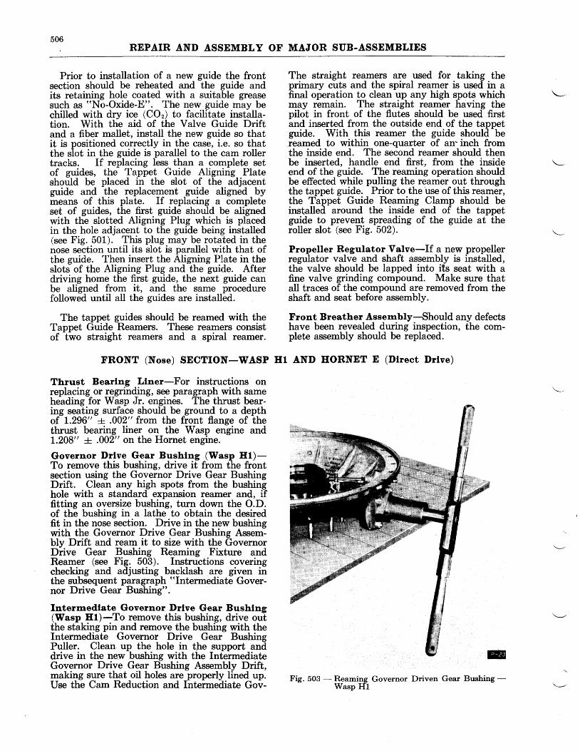
506REPAIR AND ASSEMBLY OF MAJOR SUB-ASSEMBLIES
Prior to installation of a new guide the frontsection should be reheated and the guide andits retaining hole coated with a suitable greasesuch as "No-Oxide-E". The new guide may bechilled with dry ice (COz) to facilitate installa-tion. With the aid of the Valve Guide Driftand a fiber mallet, install the new guide so thatit is positioned correctly in the case, i.e. so thatthe slot in the guide is parallel to the cam rollertracks. If replacing less than a complete setof guides, the Tappet Guide Aligning Plateshould be placed in the slot of the adjacentguide and the replacement guide aligned bymeans of this plate. If replacing a completeset of guides, the first guide should be alignedwith the slotted Aligning Plug which is placedin the hole adjacent to the guide being installed(see Fig. 501). This plug may be rotated in thenose section until its slot is parallel with that ofthe guide. Then insert the Aligning Plate in theslots of the Aligning Plug and the guide. Afterdriving home the first guide, the next guide canbe aligned from it, and the same procedurefollowed until all the guides are installed.
The tappet guides should be reamed with theTappet Guide Reamers. These reamers consistof two straight reamers and a spiral reamer.
FRONT (Nose) SECTION-WASP
Thrust Bearlng Llner-For instructions onreplacing or regrinding, see paragraph with sameheading for Wasp Jr. engines. The thrust bear-ing seating surface should be ground to a depthof L.296" + .002" from the front flange of thethrust bearing liner on the Wasp engine andt.208" + .002" on the Hornet engine.
Governor Drlve Gear Bushlng (Wasp Hl)-To remove this bushing, drive it from the frontsection using the Governor Drive Gear BushingDrift. Clean any high spots from the bushinghole with a standard expansion reamer and, iffitting an oversize bushing, turn down the O.D.of the bushing in a lathe to obtain the desiredfit in the nose section. Drive in the new bushingwith the Governor Drive Gear Bushing Assem-blv Drift and ream it to size with the GovernorDiive Gear Bushing Reaming Fixture andReamer (see Fig. 503). Instructions coveringchecking and adjusting backlash are given inthe subsequent paragraph "Intermediate Gover-nor Drive Gear Bushing".
Intermedlate Governor Drlve Gear Bushlng(Wasp Hf )-To remove this bushing, drive outthe staking pin and remove the bushing with theIntermediate Governor Drive Gear BushingPuller. Clean up the hole in the support anddrive in the new bushing with the IntermediateGovernor Drive Gear Bushing Assembly Drift,making sure tbat oil holes are properly lined up.Use the Cam Reduction and Intermediate Gov-
The straight reamers are used for taking theprimary cuts and the spiral reamer is used in afinal operation to clean yq ?ny high spotg whichmay remain. The straight reamer having thepilot in front of the flutes should be used firstand inserted from the outside end of the tappetguide. With this reamer the guide should bereamed to within one-quarter of an'inch fromthe inside end. The second reamer should thenbe inserted, handle end first, from the insideend of the guide. The reaming operation shouldbe effected while pulling the reamer out throughthe tappet guide. Prior to the use of this reamer,the Tappet Guide Reaming Clamp should beinstalled around the inside end of the tappetgurde to prevent spreading of the guide at theroller slot (see Fig. 502).
Propeller Regulator Valve-If a new propellerregulator valve and shaft assembly is installed,the valve should be lapped into its seat with afine valve grinding compound. Make sure thatall traces of the compound are removed from theshaft and seat before assembly.
Front Breather Assembly-'Should any defectshave been revealed during inspection, the com-plete assembly should be replaced.
Hl AND HORNET E (Dlrect Drlve)
Fig- 503 - Reaming Governor Driven Gear Bushing -Wasp H1
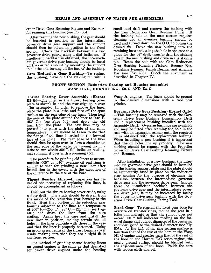
507REPAIR AND ASSEMBLY OF MAJOR SUB-ASSEMBLIES
ernor Drive Gear Reaming Fixture and Reamersfor reaming this bushing (see Fig. 504).
After reaming the new bushing, the gear shouldbe inserted in position in the intermediategovernor drive gear support and the supportshould then be bolted in position in the frontsection. Check the backlash between the twogovernor drive gears, using a dial indicator. Ifi-nsufficient backlash is obtained, the intermedi-ate governor drive gear bushing should be facedoff the desired amount by mounting the supportin a lathe and turning off the face of the bushing.
Cam Reductlon Gear Bushlng-To replacethis bushing, drive out the staking pin with a
Thrust Bearlng Cover Assernbly (HornetES-G)-The liner in the thrust bearing coverplate is shrunk in and the rear edge spun overafter assembly. In order to remove the liner,place the plate in a lathe and face off the spunSurface on-the rear edge of the liner. Then lieatthe area of the plate around the liner to 200o F.(93" C.) (see Page 501) and drive the oldliner from the plate. The new liner may bepressed into place with the plate at the samelemperature. Care should be taken to see thatthe flange of the liner is seated on the forward'face of the plate. The rear edge of the linershould then be spun over to form a shoulder onthe rear edge of the plate, by trueing up in alathe to run within .001", full indicator reading,and spinning it over with a spinning tool.
The procedure for grinCing old liners to accom-modate .005" or .010" oversize oil seal rings issimilar to that for grinding a new liner afterinstallation in the cover, with the exception ofthe difference'in the size of the bore.
Thrust Bearlng Llner-If inspection has re-vealed the necessity of replacing this liner, itshould be accomplished as follows:
Drift out the thrust bearing cover studs, usinga fiber drift. The studs should be driven fromthe inside of the reduction gear housing to thefront. Heat that portion of the reduction gearhousing adjacent to the liner to a temperqtureof 200d F.-250' F. (93' C.-t2L' C.) (see Page501) and drive the liner from the nosesection. Again heat the case and install thenew liner in position, making certain the oilholes in the liner coincide with those in the caseand that the liner is properly bottomed. Usingan arbor press, reinstall the thrust bearing coverstuds, making sure that they are a tight fit inthe front section.
The method of grinding thrust bearing linerson seared engines is the same as that describedfor
-direct drive engines under the heading
small steel drift and remove the bushing withthe Cam Reduction Gear Bushing Puller. Ifthe br,r,shing hole in the nose section requirescleaning up, an oversize bushing should beused and turned down on the O.D. to obtain thedesired fit. Drive the new bushing into theretaining boss and, using the hole in tlge case as aguide for the rf" drill, transfer-drill the stakinghole in the new bushing and drive in the stakingpin. Ream the hole with the Cam ReductionGear Bushing Reaming Fixture, Reamer Bar,Roughing Reamer, Finish Reamer and AligningBar (see Fig.505). Check the alignment asdescribed in Chapter IV.
FRONT SECTION (Reduetlon Gearlng and Houslng Assembly)wasP El-G, EoRNET E-G, E2-G AND E8-G
Wasp Jr. engines. The liners should be groundto the desired dimensions with a tool postgrinder.
Governor l)rlve Gear Bushlng (Eornet OnIy)-This bushing may be removed with the Gov-ernor Drive Gear Bushing Disassembly Driftand a replacement bushing installed with theAssembly Drift. Oversize bushings are availableand may be fitted after reaming the. hole in thecase with an expansion reamer until the requiredfit is obtained with the replacement bushing.When installing a new bushing it is importantthat the oil holes line up properly. The newbushing should be reamed with the PropellerGovernor Drive Gear Bushing Reaming Fixtureand Reamer.
After installation of a new bushing, the inter-mediate governor drive gear should be installedon the bearing support plate and the plate shouldbe temporarily fitted in place on the reductiongear housing for the purpose of checking thebacklash between the intermediate governordrive gear and the governor drive gear. Shouldthere
- be insufficient backlash between the
governor drive gear and the intermediate gover-nor drive gear, it may be increased by facingthe governor drive gear bushing with the Gov-ernor Drive Gear Bushing Facing Tool.
Flxed Gear-To regrind the fixed gear bore foroversize oil transfer rings, mount the gear in alathe and indicate so that the runout does notexceed .001" full indicator reading on the for-ward flange and outside diameter of the centeringshoulder; grind to the desired diameter (see Fig.506). As the I.D. of the ring seating surfa_ce isless than that of the rest of the bore on the WaspH1-G engine and greater than that of the rest ofthe bore-on the Hornet E-G series engines, thenewly ground surface should be blended withthe adjacent area of the bore. Polish the borewith crocus cloth and oil.
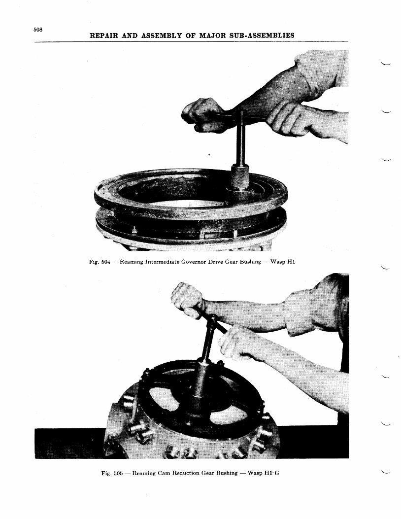
508REPAIR AND ASSEMBLY OF MAJOR SUB.ASSEMBLIES
4
Fig. 504 --- Reaming Intermediate Governor Drive Gear Bushittg - Wasp Hl
Fig. 505 - Reaming Cam Reduction Gear Bushing - Wasp Hl-G
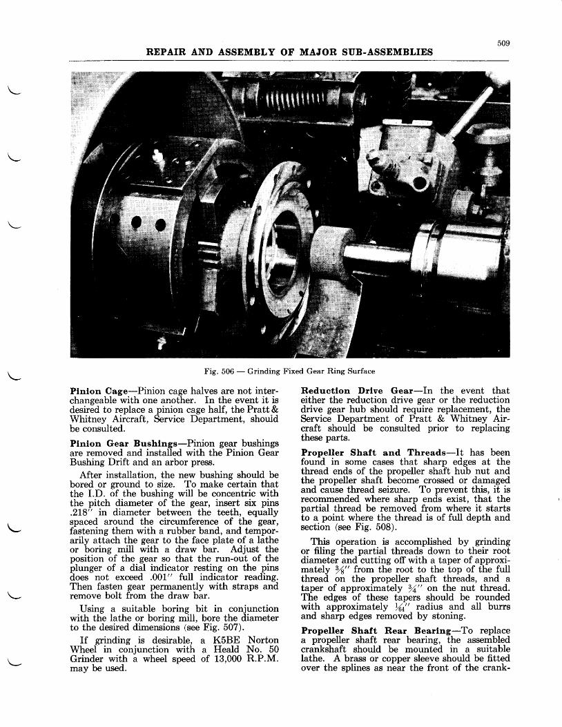
509REPAIR AND ASSEMBLY OF MAJOR SUB.ASSEMBLIES
Fig. 506 - Grinding
Plnlon Cage-Pinion cage halves are not inter-changeable with one another. In the event it isdesired to replace a pinion cage half, the Pratt &Whitney Aircraft, Service Department, shouldbe consulted.
Plnion Gear Bushlngs-Pinion gear bushingsare removed and installed with the Pinion GearBushing Drift and an arbor press.
After installation, the new bushing should bebored or ground to size. To make certain thatthe I.D. of the bushing will be concentric withthe pitch diameter of the gear, insert six pins.218" in diameter between the teeth, equallyspaced around the circumference of the Beil,fastening them with a rubber band, and tempor-arily attach the gear to the face plate of a latheor boring mill with a draw bar. Adjust theposition of the gear so that the run-out of theplunger of a dial indicator resting on the pinsdoes not exceed .001" full indicator reading.Then fasten gear permanently with straps andremove bolt from the draw bar.
Using a suitable boring bit in conjunctionwith the lathe or boring mill, bore the diameterto the desired dimensions (see Fig. 507).
If grinding is desirable, a K5BE NortonWheel in conjunction with a Heald No. 50Grinder with a wheel speed of 13,000 R.P.M.may be used.
Fixed Gear Ring Surface
Reductlon Drlve Gear-In the event thateither the reduction drive gear or the reductiondrive gear hub should require replacement, theService Department of Pratt & Whitney Air-craft should be consulted prior to replacingthese parts.
Propeller Shaft and Threads-It has beenfound in some cases that sharp edges at thethread ends of the propeller shaft hub nut andthe propeller shaft become crossed or damagedand cause thread seizure. To prevent this, it isrecommended where sharp ends exist, that thepartial thread be removed from where it startsto a point where the thread is of full depth andsection (see Fig. 508).
This operation is accomplished by grindingor fiIing the partial threads down to their rootdiameter and cutting off with a taper of approxi-mately 3f" from the root to the top of the fullthread on the propeller shaft threads, and ataper of approximately 3.4" on the nut thread.The edges of these tapers should be roundedwith approximately %t" radius and all burrsand sharp edges removed by stoning.
Propeller Shaft Rear Bearlng-To replacea propeller shaft rear bearing, the assembledcrankshaft should be mounted in a suitableIathe. A brass or copper sleeve should be fittedover the splines as near the front of the crank-
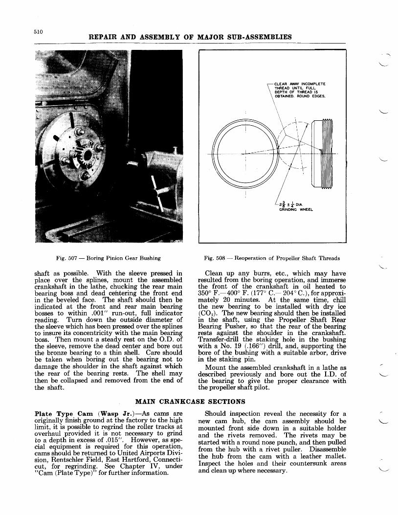
510REPAIR AND ASSEMBLY OF MAJOR SUB.ASSEMBLIES
r- CLEAR AWAY INCOMPLETE\ rxneeo uNnL FULL\ DEPTH OF THREAD IS
\ oenrNeo. RoUND EDGES.
\T
Fig. 507 - Boring Pinion Gear Bushing
shaft as possible. With the sleeve pressed inplace over the splines, mount the assembledcrankshaft in the lathe, chucking the rear mainbearing boss and dead cehtering the front endin the beveled face. The shaft should then beindicated at the front and rear main bearingbosses to within .001" run-out, full indicatorreading. Turn down the outside diameter ofthe sleeve which has been pressed over the splinesto insure its concentricity with the main bearingboss. Then mount a steady rest on the O.D. ofthe sleeve, remove the dead center and hore outthe bronze bearing to a thin shell. Care shouldbe taken when boring out the bearing not todamage the shoulder in the shaft against whichthe rear of the bearing rests. The shell maythen be collapsed and removed from the end ofthe shaft.
Fig. 508 - Reoperation of Propeller Shaft Threads
Clean up any burrs, etc., which may haveresulted from the boring operation, and immersethe front of the crankshaft in oil heated to350" F.-400" F. (177' C.- 204" C.), for approxi-mately 20 minutes. At the same time, chillthe new bearing to be installed with dry ice(COr). The new bearing should then be installedin the shaft, using the Propeller Shaft RearBearing Pusher, so that the rear of the bearingrests against the shoulder in the crankshaft.Transfer-drill the staking hole in the bushingwith a No. 19 (.166") drill, and, supporting thebore of the bushing with a suitable arbor, drivein the staking pin.
Mount the assembled crankshaft in a lathe asdescribed previously and bore out the I.D. ofthe bearing to give the proper clearance withthe propeller shaft pilot.
MAIN CRANKCASE SECTIONS
Plate Type Carn (Wasp Jr.)-As cams areoriginally finish ground at the factory to the highIimit, it is possible to regrind the roller tracks atoverhaul provided it is not necessary to grindto a depth in excess of .015". However, as spe-cial equipment is required for this operation,cams should be returned to United Airports Divi-sion, Rentschler Field, East Hartford, Connecti-cut, for regrinding. See Chapter IV, under"Cam (Plate Type)" for further information.
Should inspection reveal the necessity for anew cam hub, the cam assembly should bemounted front side down in a suitable holderand the rivets removed. The rivets may bestarted with a round nose punch, and then pulledfrom the hub with a rivet puller. Disassemblethe hub from the cam with a leather mallet.Inspect the holes and their countersunk areasand clean up where necessary.
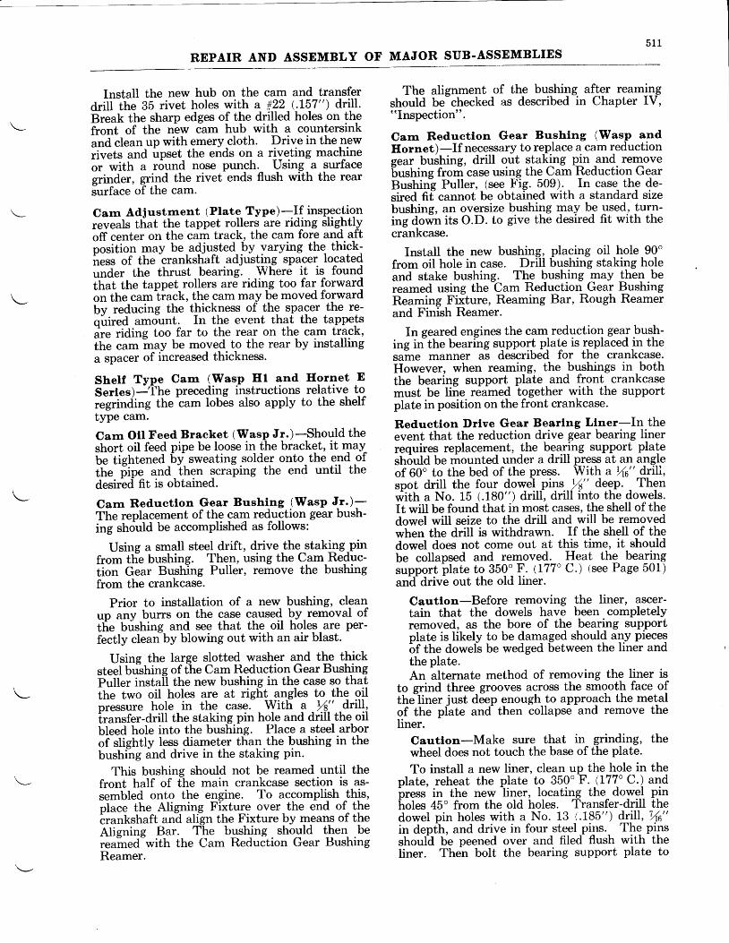
5 1 1
REPAIR AND ASSEMBLY OF MAJOR SUB-ASSEMBLIES
InstaII the new hub on the cam and transferdrill the 35 rivet holes with a #22 (-I57") drill.Break the sharp edges of the drilled holes on thefront of the n-ew Cam hub with a countersinkand clean up with emery cloth. Drive in the newrivets and upset the ends on a rlyeting machineor with a round nose punch. Using a surfacesrinder, grind the rivet ends flush with the rearSurface of the cam.
Carn Adjustrnent (Plate Type) .It insPectionreveals tiat the tappet rollers are riding slightlyoff center on the cam track, the cam fore and aftposition may be adjusted by varying the- thick-iess of the crankshaft adjusting spacer located""aut the thrust bearing. Where it is foundttrat the tappet rollers are riding too far forwardott th" camiiack, the cam may be moved forwardby reducing the thickness of the spacer the re-quired amount. In the event that the tappetsaie riding too far to the rear on the cam track,lh. .u- -uy be moved to the rear by installinga spacer of increased thickness.
Shelf Type Cam (Wastrl Hl and Hornet ESertes)-'ihe prece4iry lnstructions relative toregrinciing the cam lobes also apply to the shelftype cam.
Cam Otl Feed Bracket (\ilasp Jr.)-Should theshort oil feed pipe be loose in the bracket, it mayU" iient"ned by sweating solder onto the end ofitt. iip. and then scraping the end until thedesirbcl fit is obtained.
Cam Reductlon Gear Bushlng (Wasp Jr.)-The replacement of the cam reduction gear bush-ing should be accomplished as follows:
Using a small steel drift, drive -theistaking-pinfrom tht bushing. Then, using the Cam Reduc-tion Gear Bushing Puller, remove the bushingfrom the crankcase.
Prior to installation of a new bushing, cleanutr anv burrs on the case caused by removal oftie brishing and see that the oil holeg are per-fectly clean by blowing out with an air blast.
Using the large slotted washer and the thicksteel bushing of fhe Cam Reduction Gear BushingPuller install the new bushing in the case so thatthe two oil holes are at right angles to the oilDressure hole in the case. With a LA" drill,transfer-drill the staking pin hole and drill the oilbleed hole into the bushing. Place a steel arborof sliehtlv less diameter than the bushing in thebushing ind drive in the staking pin.
This bushing should not be reamed until thefront half of the main crankcase section is as-sembled onto the engine. To accomplish th!s,place the Aligning Fixture over the end of thecrankshaft and align the Fixture by means of theAlienine Bar. The bushing should then bereained-with the Cam Reduction Gear BushingReamer.
The atignment of the bushing. aflgr rearnilgshould be-checked as described in Chapter IV,"Inspection".
Carn Reductlon Gear Bushlng (Wasp andIlornet)-If necessary to replace a cam reductionsear bushing, drill out staking pin and removebushing from case usi4g the Cam Reduction GearBushing Puller, (see Fig. 5-09). In case the de-sired fif cannot be obtained with a standard sizebushing, an oversize bushilg +uy b-e used, turn-ing down its O.D. to give the desired fit with thecrankcase.
Install the new bushing, placing oil hole 90'from oil hole in case. Drill bushing staking holeand stake bushing. The bushing may the! bereamed using the Cam Reduction Gear BushingReaming Fiiture, Reaming Bar, Rough Reamerand Finish Reamer.
In geared engines the cam reduction geal bush-ing in"the bearing support Plat^e is replaced in thesame manner as described for the crankcase.However, when reaming, the bushings in boththe bearing support plate , and front crankcasemust be line reamed together with the supportplate in position on the front crankcase.
Reductlon Drlve Gear Bearlng Llner-In theevent that the reduction drive gear bearing linerrequires replacement, -the bgqti"g support platestuida be mounted under a drill press at an angleof 60o to the bed of the press. With a Yt6" drili,spot drill the four dowel pins tf" deep. Then*ittt a No. 15 (.180") drill, drill into the dowels.It will be found that in most cases, the shell of thedowel will seize to the drill and will be removedwhen the drill is withdrawn. If the shell of thedowel does not come out at this time, it shouldbe collapsed and removed. Heat the bearingsupport plate to 350'F. (177" C.) tsee Page 501)an-ddrive out the old liner.
Cautlon-Before removing the liner, ascer-tain that the dowels have been completelyremoved, as the bore of the bearing supportplate is likely to be damaged should any piecesbf tne dowels be wedged between the liner andthe plate.An alternate method of removing the liner is
to grind three grooves across the smooth face ofthe"liner just deep enough to approach the metalof the pl-ate and- then collapse and remove theliner.
Cautlon-Make sure that in grinding, thewheel does not touch the base of the plate.
To install a new liner, clean up the hole in theplate, reheat the plate to 350" F. -(177" C.) andpress in the new litler, Iocating the- dowgl pj"holes 45o from the old holes. Transfer-drill thedowel pin holes with a No. 13 1.185") drill, Vt6"in depth, and drive in four steel p!ls.- The pinsshoulh be peened over and filed flush with theliner. Then bolt the bearing support plate to
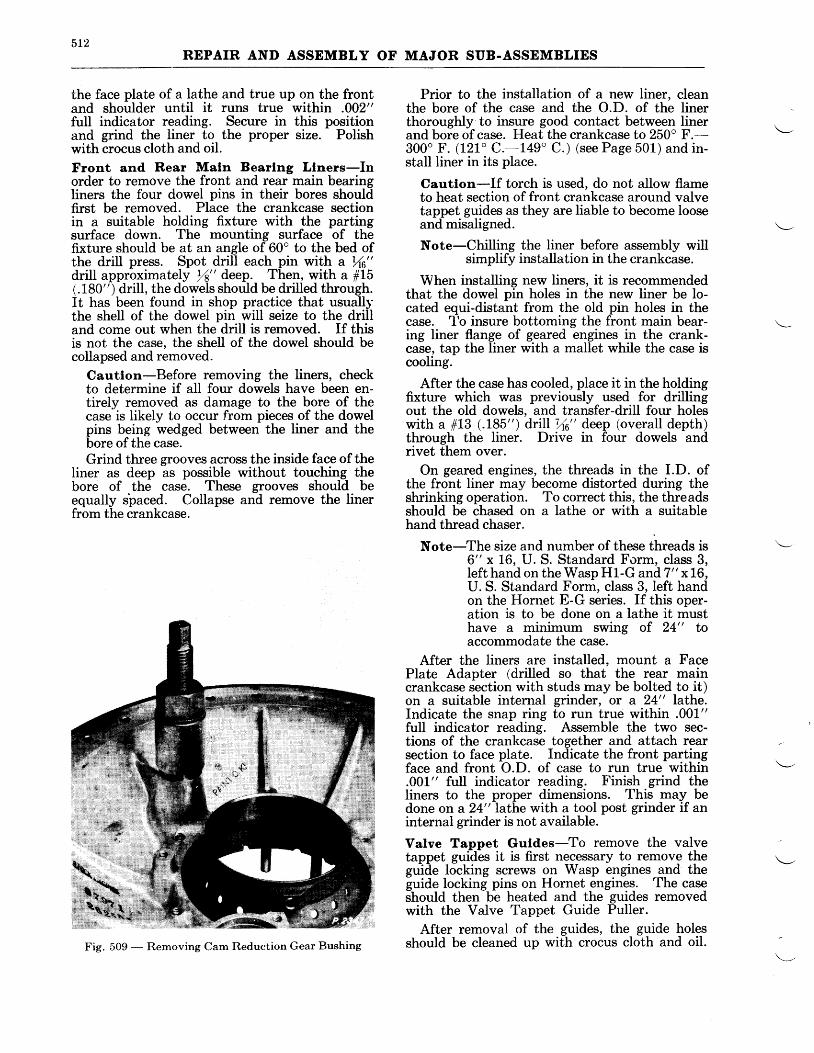
5L2REPAIR AND ASSEMBLY OF MAJOR SUB.ASSEMBLIES
the face plate of a lathe and true up on the frontand shoulder until it runs true within .002"full indicator reading. Secure in this positionand grind the liner to the proper size. Polishwith crocus cloth and oil.
Front and Rear Maln Bearlng Llners-Inorder to remove the front and rear main bearingliners the four dowel pins in their bores shouldfirst be removed. Place the crankcase sectionin a suitable holding fixture with the partingsurface down. The mounting surface of thefixture should be at an angle of 60o to the bed ofthe drill press. Spot drill each pin with a \6"drill approximately Ya" deep. Then, with a ffLi(.180") drill, the dowels should be drilled through.It has been found in shop practice that usuallythe shell of the dowel pin will seize to the drilland come out when the drill is removed. If thisis not the case, the shell of the dowel should becollapsed and removed.
Cautlon-Before removing the liners, checkto determine if all four dowels have been en-tirely removed as damage to the bore of thecase is likely to occur from pieces of the dowelpins being wedged between the liner and thebore of the case.Grind three grooves across the inside face of the
liner as deep as possible without touching thebore of the case. These grooves should beequally spaced. Collapse and remove the linerfrom the crankcase.
Prior to the installation of a new liner, cleanthe bore of the case and the O.D. of the linerthoroughly to insure good contact between linerand bore of case. Heat the crankcase to 250" F.-300' F. (121' C.-149' C.) (see Page 501) and in-stall liner in its place.
Cautlon-If torch is used, do not allow flameto heat section of front crankcase around valvetappet guides as they are liable to become looseand misaligned.
Note-Chilling the liner before assembly willsimplify installation in the crankcase.
When installing new liners, it is recommendedthat the dowel pin holes in the new liner be lo-cated equi-distant from the old pin holes in thecase. 1'o insure bottoming the front main bear-ing liner flange of geared engines in the crank-case, tap the liner with a mallet while the case iscooling.
After the case has cooled, place it in the holdingfixture which was previously used for drillingout the old dowels, and transfer-drill four holeswith a #LB (.185") driIl Vl6" deep (overall depth)through the liner. Drive in four dowels andrivet them over.
On geared engines, the threads in the I.D. ofthe front liner may become distorted during theshrinking operation. To correct this, the threadsshould be chased on a lathe or with a suitablehand thread chaser.
Note-The size and number of these threads is6" x 16, U. S. Standard Form, class 3,Ieft hand on the Wasp H1-G and7" x 16,U. S. Standard Form, class 3, left handon the Hornet E-G series. If this oper-ation is to be done on a lathe it musthave a minimum swing of 24" toaccommodate the case.
After the liners are installed, mount a FacePlate Adapter (drilled so that the rear maincrankcase section with studs may be bolted to it)on a suitable internal grinder, or a 24" Iathe.Indicate the snap ring to run true within .001"full indicator reading. Assemble the two sec-tions of the crankcase together and attach rearsection to face plate. Indicate the front partingface and front O.D. of case to run true within.001" full indicator reading. Finish grind theliners to the proper dimensions. This may bedone on a 24" Iathe with a tool post grinder if aninternal grinder is not available.
Valve Tappet Guldes-To remove the valvetappet guides it is first necessary to remove theguide locking screws on Wasp engines and theguide locking pins on Hornet engines. The caseshould then be heated and the guides removedwith the Valve Tappet Guide Puller.
After removal of the guides, the guide holesshould be cleaned up with crocus cloth and oil.Fig. 509 - Removing Cam Reduction Gear Bushing
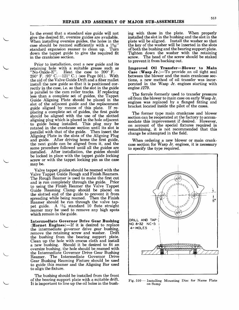
513REPAIR AND ASSEMBLY OF MAJOR SUB-ASSEMBLIES
In the event that a standard size guide will notgive the desired fit, oversize guides are available.When installing oversize guides, the holes in thecase should be reamed sufficiently with a l%2"standard expansion reamer to clean up. Turndown the tappet guide to give the required fitin the crankcase section.
Prior to installation, coat a new guide and itsretaining hole with a suitable grease such as"No-Oxide-E". Heat the case to 200" F.-250o F. (93' C.-L?L'C.) (see Page 501). Withthe aid of the Valve Guide Drift and a fiber malletinstall the new guide so that it is positioned cor-rectly in the case, i.e. so that the slot in the guideis parallel to the cam roller tracks. If replacingless than a complete set of guides, the TappetGuide Aligning Plate should be placed in theslot of the adjacent guide and the replacementguide aligned bv means of .this plate. If re-placing a complete set of guides, the first guideshould be aligned with the use of the slottedaligning plug which is placed in the hole adjacentto
- guide being installed. This plug may be
rotated in the crankcase section until its slot isparallel with that of the guide. Then insert theNigning Plate in the slots of the Aligning Plugancl guide. After driving home the first guide,the next guide can be aligned from it, and thesame procedure followed until all the guides areinstalled. After installation, the guides shouldbe locked in place with the tappet guide lockingscrew or with the tappet locking pin as the casemay be.
Valve tappet guides should be reamed with theValve Tappet Guide Rough and Finish Reamers.The Rough Reamer is used to make the first cutand is run completely through the guide. Priorto using the Finish Reamer the Valve TappetGuide Reaming Clamp should be placed onthe slotted end of the guide to prevent it fromspreading while being reamed. Then the FinishReamer should be run through the valve tap-pet guide. A |rA standard 10 flute straightieamer may be used to remove any high spotswhich remain in the guide.
Intermedlate Governor Drlve Gear Bushlng(Hornet Englnes)-If it is desired to replacethe intermediate governor drive gear bushing,remove the retaining screw and washer. Driftthe bushing from the bearing support plate.Clean up the hole with crocus cloth and installa new bushing. Should it be desired to fit anoversize bushing, the hole should be reamed withthe Intermediate Governor Drive Gear BushingReamer. The Intermediate Governor DriveGear Bushing Reaming Fixture should be usedto guide this reamer and the Aligning Bar usedto align the fixture.
The bushing should be installed from the frontof the bearing support plate with a suitable drift.It is important to line up the oil holes in the bush-
ing with those in the plate. When properlyinstalled the slot in the bushing and the slot in theplate will be aligned. Install the washer so thatthe key of the riasher will be inserted in the slotsof both the bushing and the bearing support plate.Tighten down the washer with the retainingscrew. The head of the screw should be stakedto prevent it from backing out.
Improved Otl Transfer-Blower to MalnCase (Wasp Jr.)-To provide an oil tight sealbetween the blower and the main crankcase sec-tions, a new method of oil transfer was incor-porated in the Wasp Jr. engines starting withengine #279.
The ferrule formerly used to transfer pressureoil from the blower to main case on early Wasp Jr.engines was replaced by a flanged fitting andbracket located inside the pilot of the cases.
The former type main crankcase and blowersection can be reoperated at the factory to accom-modate this improvement if desired. However,on account of the special fixtures required inremachining, it is not recommended that thischange be attempted in the field.
When ordering a new blower or main crank-case section for Wasp Jr. engines, it is necessaryto specify the type required.
Fig. 510 - Installing Mounting Disc for Name Plateon Sump
DRILL AND TAPNO. 8-32 NC-34- HOLES
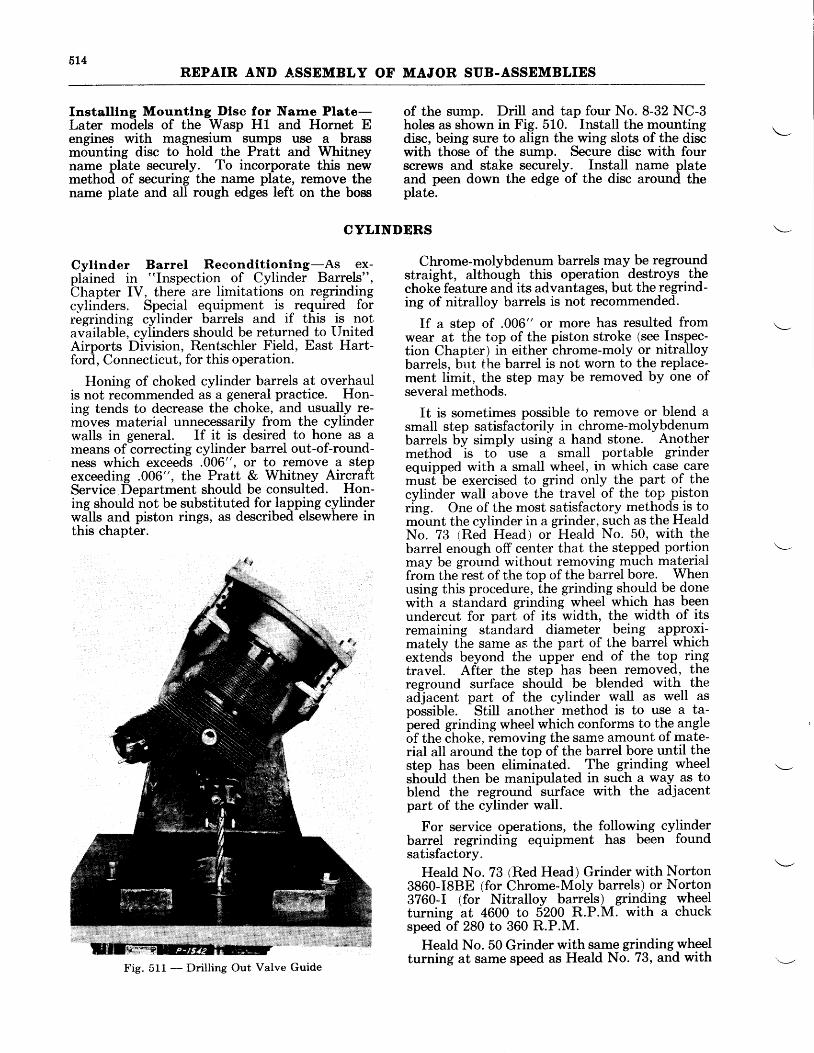
5L4REPAIR AND ^ASSEMBLY OF MAJOR SUB.ASSEMBLIES
Installlng Mountlng Dlsc for Name Plate-Later models of the Wasp Hl and Hornet Eengines with magnesium sumps use a brassmounting disc to hold the Pratt and Whitneyname plate securely. To incorporate this newmethod of securing the name plate, remove thename plate and all rough edges left on the boss
of the sump. Drill and tap four No. 8-32 NC-3holes as shown in Fig. 510. Install the mountingdisc, being sure to align the wing slots of the discwith those of the sump. Secure disc with fourscrews and stake securely. Install name plateand peen down the edge of the disc around theplate.
CYLINDERS
Cylinder Barrel Reconditioning-As ex-plained in "Inspection of Cylinder Barrels",Chapter IV, there are limitations on regrirrdingcylinders. Special equipment is required forregrinding cylinder barrels and if this is notavailable, cylinders should be returned to UnitedAirports Division, Rentschler Field, East Hart-ford, Connecticut, for this operation.
Honing of choked cylinder barrels at overhaulis not recommended as a general practice. Hon-ing tends to decrease the choke, and usually re-moves material unnecessarily from the cylinderwalls in general. If it is desired to hone as ameans of correcting cylinder banel out-of-round-ness which exceeds .006", or to remove a stepexceeding .006", the Pratt & Whitney AircraftService Department should be consulted. Hon-ing should not be substituted for lapping cylinderwalls and piston rings, as described elsewhere inthis chapter.
Chrome-molybdenum barrels may be regroundstraight, although this operation destroys .thechoke feature and its advantages, but the regrind-ing of nitralloy barrels is not recommended.
If a step of .006" or more has resulted fromwear at the top of the piston stroke (see Inspec-tion Chapter) in either chrome-moly or nitralloybarrels, but the barrel is not worn to the replace-ment limit, the step may be removed by one ofseveral methods.
It is sometimes possible to remove or blend asmall step satisfactorily in chrome-molybdenumbarrels by simply using a hand stone. Anothermethod is to use a small portable grinderequipped with a small wheel, in which case caremusf be exercised to grind only the part of thecylinder wall above the travel of the top _pistonring. One of the most satisfactory methods is tomount the cylinder in a grinder, such as the HealdNo. 73 (Red Head) or Heald No. 50, with thebarrel enough off center that the stepped portionmay be ground without removing much mate-rialfrom thelest of the top of the barrel bore. Whenusing this procedure, the grinding shoul4 b. donewitti a standard grinding wheel which has beenundercut for parf of its width, the width of itsremaining standard diameter being a-pploxi-mately the same as the part of the barrel whichextends beyond the upper end of the top ringtravel. After the step-has been removed, thereground surlhce should be blended with theadJacent part of the cylinder wall as well aspossible. Still another method is to use a ta-pered grinding wheel which conforms to the anglebf the choke, iemoving the same amount of mate-rial all around the top of the barrel bore until thestep has been eliminated. The grinding wheelshould then be manipulated in such a way as toblend the reground surface with the adjacentpart of the cylinder wall.
For service operations, the followlng cylinderbarrel regrinding equipment has been foundsatisfactory.
Heald No. 73 (Red Head) Grinder with Norton3860-I8BE (for Chrome-Moly barrels) or Norton3?60-I (for Nitralloy barrels) grinding wheelturning at 4600 to SZOO R.P.M. with a chuckspeed of 280 to 360 R.P.M.
Heald No. 50 Grinder with same grinding wheelturning at same speed as Heald No. 73, and with
Fig. 511 - Drilling Out Valve Guide
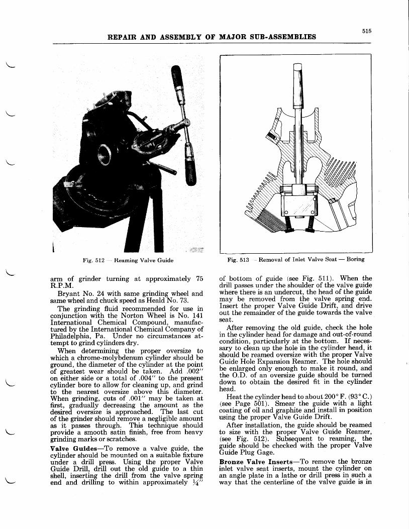
A I D
REPAIR AND ASSEMBLY OF MAJOR SUB.ASSEMBLIES
Fig. 513 - Removal of Inlet Valve Seat - BoringFig. 512 - Reaming Valve Guide
arm of grinder turning at approximately 75R.P.M.
Bryant No. 24 with same grinding wheel andsame wheel and chuck speed as Heald No. 73.
The grinding fluid recommended for use inconjunction with the Norton Wheel is No. l4lInternational Chemical Compound, manufac-tured by the International Chemical Company ofPhiladelphia, Pa. Under no circumstances at-tempt to grind cylinders dry.
When determining the proper oversize towhich a chrome-molybdenum eylinder should beground, the diameter of the cylinder at the pointof greatest wear should be taken. Add .002"on either side or a total of .004" to the presentcylinder bore to allow for cleaning up, and grindto the nearest oversize above this diameter.When grinding, cuts of .001" may be taken atfirst, gradually decreasing the amount as thedesired oversize is approached. The last cutof the grinder should remove a negligible amountas it passes through. This technique shouldprovide a smooth satin finish, free from heavygrinding marks or scratches.Valve Guides-To remove a valve guide, thecylinder should be mounted on a suitable fixtureunder a drill press. Using the proper ValveGuide Drill, drill out the old guide to a thinshell, inserting the drill from the valve springend and drilling to within approximately rA"
of bottom of guide (see Fig. 511). When thedrill passes under the shoulder of the valve guidewhere there is an undercut, the head of the guidemay be removed from the valve spring end.Insert the proper Valve Guide Drift, and driveout the remainder of the guide towards the valveseat.
After removing the old guide, check the holein the cylinder head for damage and out-of-roundcondition, particularly at the bottom. If neces-sary to clean up the hole in the cylinder head, itshould be reamed oversize with the proper ValveGuide Hole Expansion Reamer. The hole shouldbe enlarged only enough to make it round, andthe O.D. of an oversize guide should be turneddown to obtain the desired fit in the cylinderhead.
Heat the cylinder head to about 2A0" F. (93 ' C. )(see Page 501-). Smear the guide with a lightcoating of oil and graphite and install in positionusing the proper Valve Guide Drift.
After installation, the guide should be reamedto size with the proper Valve Guide Reamer,(see Fig. 5L2). Subsequent to reaming, theguide should be checked with the proper ValveGuide Plug Gage.Bronze Valve Inserts-To remove the bronzeinlet valve seat inserts, mount the cylinder onan angle plate in a lathe or drill press in such away that the centerline of the valve guide is in
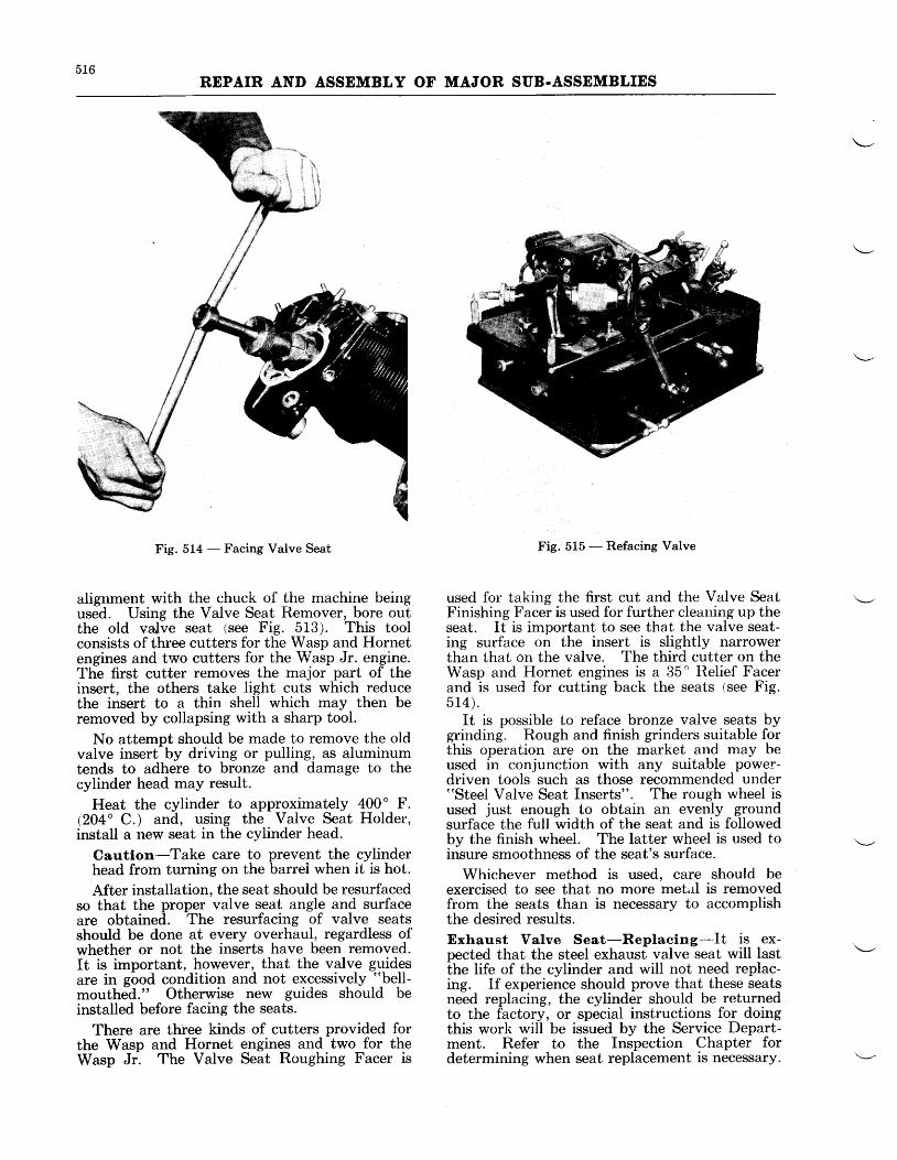
516REPAIR AND ASSEMBLY OF MAJOR SUB.ASSEMBLIES
Fig. 514 - Facing Valve Seat
alignment with the chuck of the machine beingused. Using the Valve Seat Remover, bore outthe old valve seat (see Fie. 513). This toolconsists of three cutters for the Wasp and Hornetengines and two cutters for the Wasp Jr. engine.The first cutter removes the major part of theinsert, the others take light cuts which reducethe insert to a thin shell which may then beremoved by collapsing with a sharp tool.
No attempt should be made to remove the oldvalve insert by driving or pulling, as aluminumtends to adhere to bronze and damage to thecylinder head may result.
Heat the cylinder to approximately 400" F.(204" C.) and, using the Valve Seat Holder,install a new seat in the cylinder head.
Caution-Take care to prevent the cylinderhead from turning on the banei when it is hot.
After installation, the seat should be resurfacedso that the proper valve seat angle and surfaceare obtained. The resurfacing of valve seatsshould be done at every overhaul, regardless ofwhether or not the inserts have been removed.It is important, however, that the valve guidesare in good condition and not excessively "bell-
mouthed." Otherwise new guides should beinstalled before facing the seats.
There are three kinds of cutters provided forthe Wasp and Hornet engines and two for theWasp Jr. The Valve Seat Roughing Facer is
Fig. 515 - Refacing Valve
used for taking the first cut and the Valve SeatFinishing Facer is used for further cleauing up theseat. It is important to see that the valve seat-ing surface on the insert is slightly narrowerthan that on the valve. The third cutter on theWasp and Hornet engines is a 35' Relief Facerand is used for cutting back the seats (see Fig.5r4).
It is possible to reface bronze valve seats bygrinding. Rough and finish grinders suitable forthis operation are on the market and may beused in conjunction with any suitable power-driven tools such as those recommended under"Steel Valve Seat Inserts". The rough wheel isused just enough to obtain an evenly groundsurface the full width of the seat and is followedby the finish wheel. The latter wheel is used toinsure smoothness of the seat's surface.
Whichever method is used, care should beexercised to see that no more metal is removedfrom the seats than is necessary to accomplishthe desired results.Exhaust Valve Seat-Replaeing-It is ex-pected that the steel exhaust valve seat will lastthe life of the cylinder and will not need replac-ing. If experience should prove that these seatsneed replacing, the cylinder should be returnedto the factory, or special instructions for doingthis work will be issued by the Service Depart-ment. Refer to the Inspection Chapter fordetermining when seat replacement is necessary.
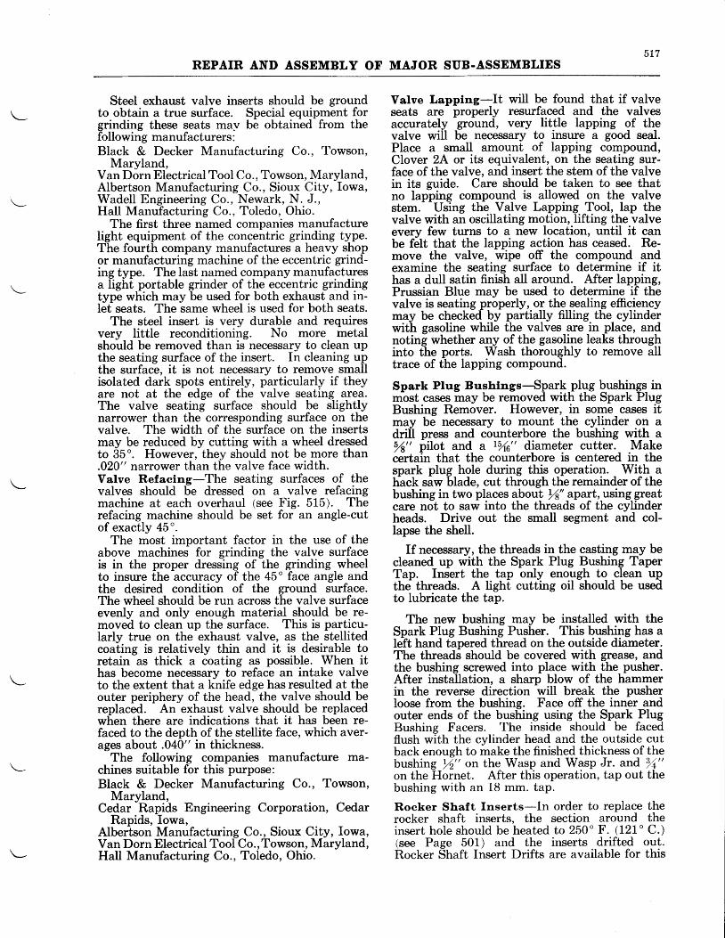
5L7REPAIR AND ASSEMBLY OF MAJOR SUB.ASSEMBLIES
Steel exhaust valve inserts should be groundto obtain a true surface. Special equipment forgrinding these seats may be obtained from thefollowing manufacturers :Black & Decker Manufacturing Co., Towson,
Maryland,Van Dorn Electrical Tool Co., Towson, Maryland,Albertson Manufacturing Co., Sioux City, Iowa,Wadell Engineering Co., Newark, N. J.,HaIl Manufacturing Co., Toledo, Ohio.
The first three named companies manufacturelight equipment of the concentric grinding type.The fourth company manufactures a heavy shopor manufacturing machine of the eccentric grind-ing type. The last named company manufacturesa light portable grinder of the eccentric grindingtype which may be used for both exhaust and in-let seats. The same wheel is used for both seats.
The steel insert is very durable and requiresvery little reconditioning. No more metalshould be removed than is necessary to clean upthe seating surface of the insert. In cleaning upthe surface, it is not necessary to remove smallisolated dark spots entirely, particularly if theyare not at the edge of the valve seating area.The valve seating surface should be slightlynarrower than the corresponding surface on thevalve. The width of the surface on the insertsmay be reduced by cutting with a wheel dressedto 35o. However, they should not be more than.020" narrower than the valve face width.Valve Refaclng-The seating surfaces of thevalves should be dressed on a valve refacingmachine at each overhaul (see Fig. 515). Therefacing machine should be set for an angle-cutofexactly 45".
The most important factor in the use of theabove machines for grinding the valve surfaceis in the proper dressing of the grinding wheelto insure the accuracy of the 45" face angle andthe desired condition of the ground surface.The wheel should be run across the valve surfaceevenly and only enough material should be re-moved to clean up the surface. This is particu-larly true on the exhaust valve, as the stellitedcoating is relatively thin and it is desirable toretain as thick a coating as possible. When ithas become necessary to reface an intake valveto the extent that a knife edge has resulted at theouter periphery of the head, the valve should bereplaced. An exhaust valve should be replacedwhen there are indications that it has been re-faced to the depth of the stellite face, which aver-ages about .040" in thickness.
The following companies manufacture ma-chines suitable for this purpose:Black & Decker Manufacturing Co., Towson,
Maryland,Cedar Rapids Engineering Corporation, Cedar
Rapids, Iowa,Albertson Manufacturing Co., Sioux City, Iowa,Van Dorn Electrical Tool Co.,Towson, Maryland,Hall Manufacturing Co., Toledo, Ohio.
Valve Lapplng-It will be found that if valveseats are properly resurfaced and the valvesaccurately ground, very little lapping of thevalve will be necessary to insure a good seal.Place a small amount of lapping compound,Clover 2A or its equivalent, on the seating sur-face of the valve, and insert the stem of the valvein its gurde. Care should be taken to see thatno lapping compound is allowed on the valvestem. Using the Valve Lapping Tool, lap thevalve with an oscillating motion, Iifting the valveevery few turns to a new location, until it canbe felt that the lapping action has ceased. Re-move the valve, wipe off the compound andexamine the seating surface to determine if ithas a dull satin finish all around. After lapping,Prussian Blue may be used to determine if thevalve is seating properly, or the sealing efficiencymay be checked by partially fi.lling the cylinderwith gasoline while the valves are in place, andnoting whether any of the gasoline leaks throughinto the ports. Wash thoroughly to remove alltrace of the lapping compound.
Spark Plug Bushlngs-'Spark plug bushings inmbst cases may be removed with the Spark PlugBushing Remover. However, in some cases itmay be necessary to mount the cylinder on adrill press and counterbore the bushing with a,{ t pilot and a Lyr6" diameter cutter. Make6drtain that the counterbore is centered in thespark plug hole during this operation. With ahack siw 6tade, cut thiough tlie remainder of thebushing in two places about rf" apart, using greatcare not to saw into the threads of the cylinderheads. Drive out the small segment and col-lapse the shell.
If necessary, the threads in the casting may becleaned up with the Spark Plug Bushing TaperTan. Insert the tap onlv enoush to clean upupT"p,. Insert tJtq. tup otly eno.ugh tothe threads. A Iight cutting oil should be usedto lubricate the tap.
The new bushing may be installed with theSpark Plug Bushing Pusher. This bushing has aIeft hand tapered thread on the outside diameter.The threads should be covered with grease, andthe bushing screwed into place with the pusher.After installation, a sharp blow of the hammerin the reverse direction will break the pusherloose from the bushing. Face off the inner andouter ends of the bushing using the Spark PlugBushing Facers. 'Ihe inside should be facedflush with the cylinder head and the outside cutback enough to make the finished thickness of thebushing r/2" ott the Wasp and Wasp Jr. and 3,/+"on the Hornet. After this operation, tap out thebushing with an 18 mm. tap.
Roeker Shaft Inserts-In order to replace therocker shaft inserts, the section around theinsert hole should be heated to 250" F. (121'C.)(see Page 501) and the inserts drifted out.Rocker Shaft Insert Drifts are available for this
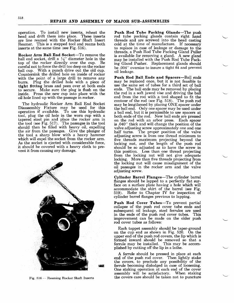
518REPAIR AND ASSEMBLY OF MAJOR SUB.ASSEMBLIES
operation. To install new inserts, reheat theh-ead and drift them into place. These insertsare line reamed with the Rocker Shaft InsertReamer. This is a stepped tool and reams bothinserts at the same time (see Fig. 516).
Rocker Arm Ball End Socket-To remove thebaII end socket, drill a rf" diarneter hole in thetop of the rocker directly over the cup. Becareful not to force the drill too deep on the rockerball cup. With a punch drive out the old cup.Countersink the drilled hole on inside of rockerwith the point of a large drill to remove anyburrs. PIug the drilled hole with a piece ofttght fitttng brass and peen over at both endsto secure. Make sure the plug is flush on theinside. Press the new cup into place with theoil hole lined up with the passage in rocker.
The hydraulic Rocker Arm Ball End SocketDisassembly Fixture may be used for thisoperation if available. To use this hydraulictool, plug the oil hole in the worn cup with atapered steel pin and place the rocker arm inthe tool (see Fig. 5I7). The passages in the toolshould then be filled with heavy oil, expellingthe air from the passages. Give the plunger ofthe tool a sharp blow with a heavy hammerwhich will expel the socket from the rocker arm.As the socket is ejected with considerable force,it should be covered with a heavy cloth to pre-vent it from causing any damage.
Push Rod Tube Packlng Glands-The pushrod tube packing glands contain right handthreads and are screwed into the head castingcold at the time of manufacture. If necessaryto replace in case of leakage or damage to thethreads, a Push Rod Tube Packing Gland Pulleris available for removing a gland. A new glandmay be installed with the Push Rod Tube Pack-ing Gland Pusher. Replacement glands shouldbe .004" oversize to insure a tight fit and preventoil leakage.
Push Rod Ball Ends and Spacers-Ball endsmay be replaced once, but it is not feasible touse the same set of tubes for a third set of ballends. The ball ends may be removed by placingthe rod in a soft jawed vise and driving the ballend from the rod with a tool shaped to fit thecontour of the rod (see Fig. 518). The push rodmay be lengthened by placing ONE spacer underthe ball end. Only one spacer may be used undera ball end, but it is permissible to use spacers atboth ends of the rod. New ball ends are pressedon the rod with an arbor press. Each spaceris .040" thick and will change the position of thevalve adjusting screw approximately one and onehalf turns. L'he proper position of the valveadjusting screw is from one thread minimum tofive threads maximum projecting beyond thelocking nut, and the length of the push rodshould be so adjusted as to have the screw inthis position. Less than one thread projectingfrom the locking nut will not give adequatelocking. More than five threads projecting fromthe locking nut will cause misalignment of theoil passages in the rocker arm and the valveadjusting screw.
Cyllnder Barrel Flanges-The cylinder barrelflanges should be lapped to a perfectly flat sur-face on a surface plate having a hole which willaccommodate the skirt of the banel (see Fig.519). Refer to Chapter IV for inspection ofcylinder barrel flanges previous to lapping.
Push Rod Cover Tubes-To prevent partialcollapse of the push rod cover tube ends andsubsequent oil leakage, steel ferrules are usedin the ends of the push rod cover tubes. Thisimprovement can be made on the older pushrod cover tubes as follows:
Each tappet assembly should be taper-groundon the cup end as shown in Fig. 520. On theupper end of the push rod covers, the lip which isformed inward should be removed so that aferrule may be installed. This may be accom-plished by cutting off the lip in a lathe.
A ferrule should be pressed in place at eachend of the push rod cover. Then lightly stakethe covers, to preclude any possibility of theferrule becoming dislodged in case of loosening.One staking operation at each end of the coverassembly will be satisfactory. When stakingthe covers care should be taken not to punctureFig. 516 -- Reaming Rocker Shaft Inserts
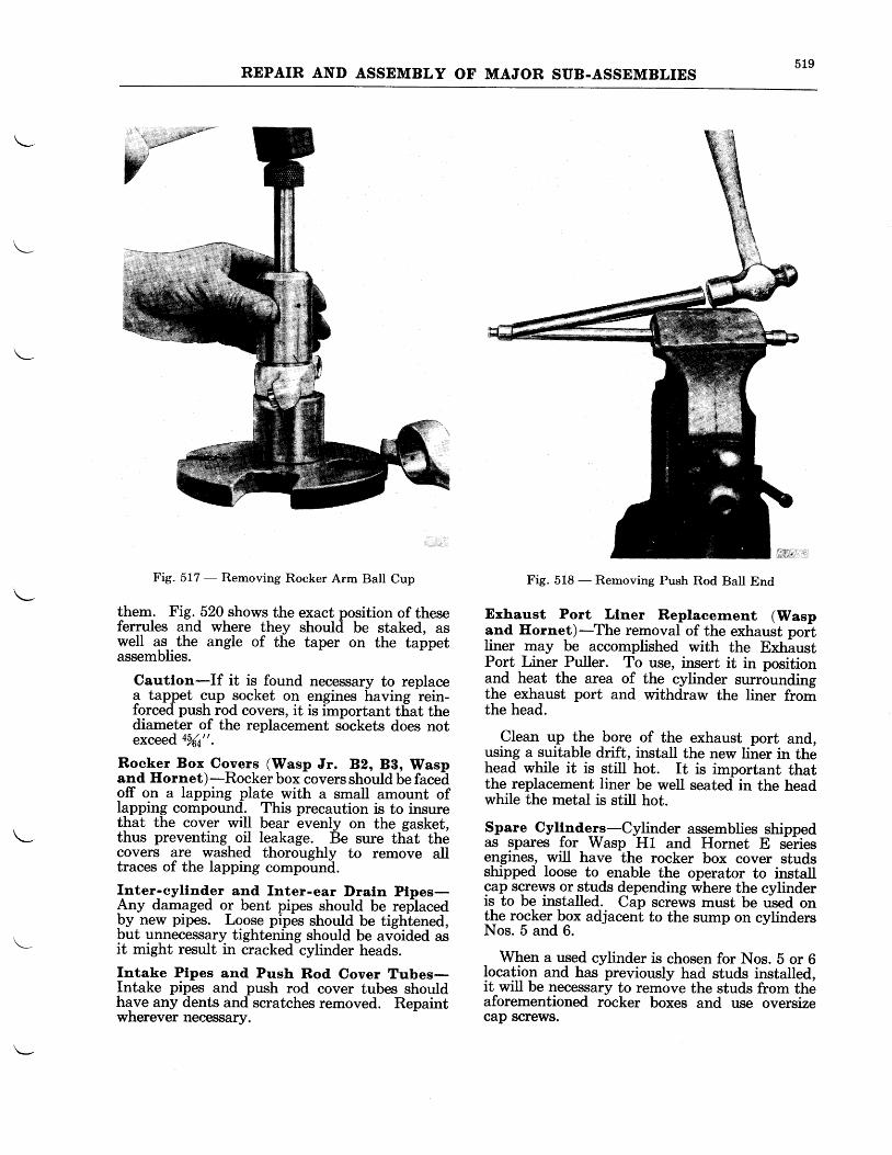
519REPAIR AND ASSEMBLY OF IVIAJOR SUB.ASSEMBLIES
Fig. 517 - Removing Rocker Arm Ball Cup
them. Fig. 520 shows the exact position of theseferrules and where they shoultl be staked, aswell as the angle of the taper on the tappetassemblies.
Cautlon-If it is found necessary to replacea tappet cup socket on engines having rein-f,orced push rod covers, it is important tf,at thediameter of the replacement sbckets does notexceed a%a".
Rocker Box Covers (Wasp Jr. 82, 88, Waspand Hornet)-Rocker box
-covers should 6e faceh
off on a lapping plate with a small amount oflapping compound. This precaution is to insurethat the cover will bear evenly on the gasket,thus preventing oil leakage. Be sure that thecovers are washed thoroughly to remove alltraces of the lapping compound.
Inter_-cyllnd_er and Inter-ear Draln Plpes-Ary damaged or bent pipes should be replacedFy new pipes. Loose pipes should be tightened,but unnecessary tightening should be avoided asit might result in cracked cylinder heads.
fntake Plpes and Push Rod Cover Tubes-Intake pipes and push rod cover tubes shouldhave any dents and scratches removed. Repaintwherever necessary.
Fig. 518 - Removing Push Rod Ball End
Exhaust Port Llner Replacernent (Waspand Eornet)-The removal of the exhaust portIiner may be accomplished with the ExhaustPort Liner Puller. To use, insert it in positionand heat the area of the cylinder surroundingthe exhaust port and withdraw the liner fromthe head.
Clean up the bore of the exhaust port and,using a suitable drift, install the new liner in thehead while it is still hot. It is important thatthe replacement liner be well seated in the headwhile the metal is still hot.
Spare Cyltnde_Ig-Cylinder assemblies shippedas spares for Wasp H1 and Hornet E s-ei{esengines, will have the rocker box cover studsshipped loose to enable the operator to installcap screws or.qtuds depending where the cylinderis to be installed. Cap screws must be rised onthe rocker box adjacenl to the sump on cylindersNos. 5 and 6.
When a used cylinder is chosen for Nos. b or 6location and has previously had studs installed,it will be necessary to remove the studs from theaforementioned rocker boxes and use oversizecap screws.
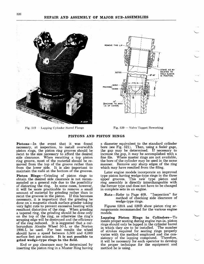
520REPAIR AND ASSEMBLY OF MAJOR SUB-ASSEMBLIES
REMOVE THIS LIP
Fig. 519 Lapping Cylinder Barrel Flange
PISTONS AND
Plstons-In the event that it was foundnecessary, at inspection, to install overwidthpiston rings, the piston ring grooves should berecut to the size necessary to afford the desiredside clearance. When recutting a top pistonring groove, most of the material should be re-moved from the top of the groove rather thanfrom the lower side. It is also important tomaintain the radii at the bottom of the grooves.
Plston Rlngs-Grinding of piston rings toobtain the desired side clearance is not recom-mended as a general rule due to the possibilityof distorting the ring. In some cases, however,it will be more practicable to remove a smallamount of material by grinding rather than torecut the grooves in the piston. If this becomesnecessary, it is important that the grinding bedone on a magnetic chuck surface grinder takingvery tight cuts to prevent excessive heating withresultant distortion of the ring. When grindinga tapered ring, the grinding should be done onlyon the top of the ring, as otherwise the ring'sscraping edge will be destroyed and the efficiencyof the ring reduced. It is suggested that a car-borundum Aloxite Wheel 50-L or the Norton1906-L be used. For best results the wheelshould have a speed between 5,500 and 6,000surface feet per minute. It is not posslble togrlnd wedge-type rlngs ln the ffeld.
End or gap clearance may be determined byinserting the piston ring in a Master Ring having
STAKE AS IN-DICATED TOHOLD SLEEVEtN POSITION.
y9282PACKtNGI
rt4096
1go--------J(ulcnrrue ro Mrssi.o. or coven)
Fig. 520 - Valve Tappet Reworking
PISTON RINGS
a diameter equivalent to the standard cylinderbore (see Fig. 52L). Then, using a feeler gage,the gap may be determined. If necessary toincrease the gap, it may be accomplished with afine file. Where master rings are not available,the bore of the cylinder may be used in the samemanner. Remove any sharp edges of the ringwhich may have resulted from the filing.
Later engine models incorporate an improvedtype piston having wedge-type rings in the threeupper grooves. This new type piston andring assembly is directly interchangeable withthe former type and does not have to be changedin complete sets in an engine.
Note-Refer to Page 409. "Inspection" formethod of checking side clearance ofwedge-type rings.
Figures 520A and 520B show piston ring ar-rangements recommended for the various enginemodels.
I,apptng Ptstol Rfngs tn . Cylinders-Toinsure proper seating during engine run-in, pistonrings should only be lapped in the cylinder barrelin which they are to be installed. The numberof strokes required for seating rings properlyvaries with the method employed and the con-sistency of the lapping compound. Therefore,it will be necessary for each operator to developthe proper technique for the equipment andmethod he is using.
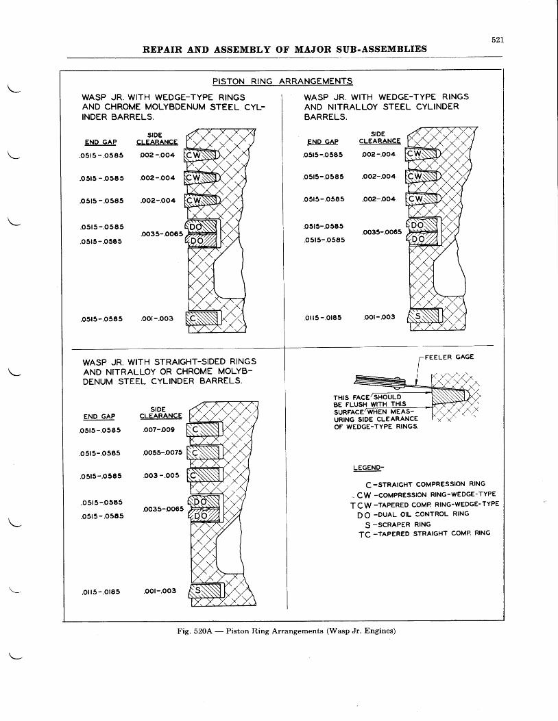
52LREPAIR AND ASSEMBLY OF MAJOR SUB.ASSEMBLIES
PISTON RING ARRANGEMENTS
WASP JR. WITH WEDGE-TYPE RINGSAND CHROME MOLYBDENUM STEEL CYL-INDER BARRELS.
SIDEEND GAP CLEARANCE
.o5r5 -.0585 .o02 -.OO4
.o5r5 - '0565 'o02-.OO4
.o5t5 -.0585 .OO2-.OO4
.o5r5-.o585
.o5r5-.o585.oo35-0065
.o5r5-.o585 .oot-.oo3
WASP JR. WITH STRAIGHT-SIDED RINGSAND NITRALLOY OR CHROME MOLYB-DENUM STEEL CYLINDER BARRELS.
WASP JR. WITH WEDGE-TYPE RINGSAND NITRALLOY STEEL CYLINDERBARRELS.
SIDEENO GAP CLEARANCE
.05t5-.0585 .o02-.OO4
o5r5-.o585 .OO2-.OO4
.05r5-.o585 .OO2-.OO4
o5t5-.o585.oo35-0065
.o5t5-.o585
.oi ls -.0185 .OOl-.OO3
FEELER GAGE
THIS FACE/SHOULDBE FLUSH WITH THISSURFACE/WHEN MEAS-URING SIDE CLEARANCEOF WEDGE.TYPE RINGS.
END GAP
.o515- .o585
.05r5-.o585
.o5t5- .O585
.o5r5-O585
.o5r5- .O585
SIDECLEARANCE
.o07-oo9
oo5s-.oo75
.oo3 -.oos
.oo35-0065
LEGEND-
c -STRAIGHT COMPRESSION RING
- CW -coMPREssloN RING-wEDGE-TYPE
TCW -TAPERED COMP RING.WEDGE.TYPE
D O -DUAL OIL CONTROL RING
S -SCRAPER RING
TC -TAPERED STRAIGHT COMP. RING
Fig. 520.4' - Piston Ring Arrangements (Wasp Jr. Engines)
.o i l5- .O185 .oor-.oo3
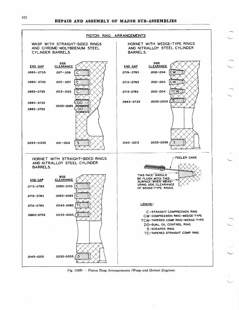
522REPAIR AND ASSEMBLY OF MAJOR SUB.ASSEMBLIES
END GAP
'0665-.O735
o665-.O735
o665-O735
END GAP
.o7t5-.o785
'o7r5-o785
.o7t5-o785
.o665-.O735
SIDECLEARANCE
.oo7-.oo9
oo5-.oo7
.oo3-.oo5
o035-.0065
SIDECLEARANCE
.o085-oto5
.0065-oo85
oo45-.o065
oo35-.o055
.oo35-oo55
WASP WITH STRAIGHT-SIDED RINGSAND CHROME- MOLYBDENUM STEELCYLINDER BARRELS.
PISTON RING ARRANGEMENTS
END GAP
.o7r5-.o785
.07t5-.o785
.o7t5-.0785
.o665-.o735
.o145- .o215
HORNET WITH WEDGE-TYPE RINGSAND NITRALLOY STEEL CYLINDERBARRELS.
SIDECLEARANCE
.oo2-.o04
oo2-oo4
oo2-.oo4
oo35-oo55
oo35-o055
FEELER GAGE
URING SIDE CLEARANCEOF WEDGE.TYPE RINGS.
LEGEND-
c-srRArGHT COMPRESSION RING
cw-coMPREssloN RING-WEDGE- TYPE
TCW-TAPERED COMP RING.WEDGE- TYPE
DO-DUAL OIL CONTROL RING
S-SCRAPER RING
TC-TAPERED STRAIGHT COMP RING
.0265-O335 .oor- .0o3
HORNET WITH STRAIGHT-SIDED RINGSAND NITRALLOY STEEL CYLINDERBARRELS.
THIS FACE/ SHOULDBE FLUSH WITH THIS
Fig. 5208 - Piston Ring Arrangements (Wasp and Hornet Engines)
or45-o2r5
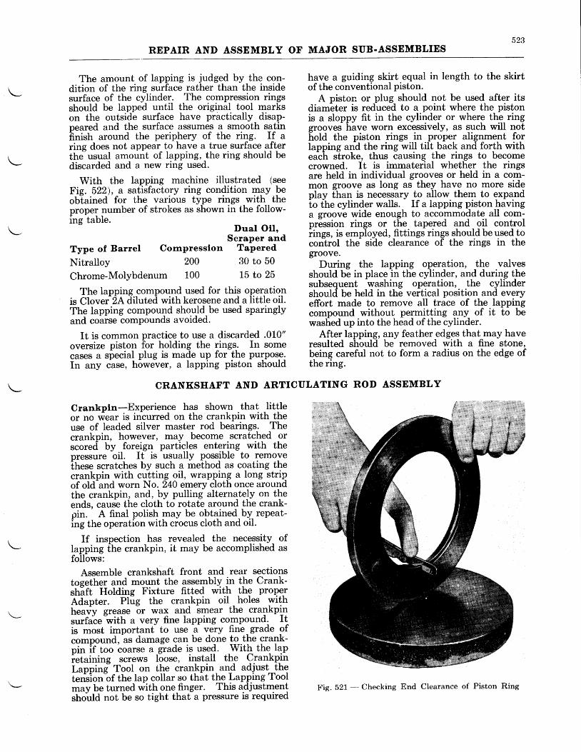
523REPAIR AND ASSEMBLY OF MAJOR SUB.ASSEMBLIES
The amount of lapping is judged by the con-dition of the ring surface rather than the insidesurface of the cylinder. The compression ringsshould be lapped until the original tool markson the outsid-e surface have practically disap-peared and the surface assumes a smooth satinfrnish around the periphery of the ring. If aring does not appear- to ha-ve a true surface afterthe usual amount of lapping, the ring should bediscarded and a new ring used.
With the lapping machine illustrated (seeFie. 522), a satisfactory ring condition may beobtained for the various type rings with theproper number of strokes as shown in the follow-ing table
Duar oil,Scraper and
Type of Barrel Cornpresslon Tapered
Nitralloy 200 30 to 50
Chrome-Molybdenum 100 15 to 25
have a guiding skirt equal in length to the skirtof the conventional piston.
A piston or plug should not be used after itsdiameter is reduced to a point where the pistonis a sloppy fit in the cylinder or where the ringgrooves have worn excessively, as qgch will nothold the piston rings in proper alignment forIapping an-d the ring will tilt back and forth withe"ch s"troke, thus causing the rings to becomecrowned. It is immaterial whether the ringsare held in individual grooves or held in a com-mon groove as long as they have no more sideplay fhan is necessary to allow them to expandio fhe cylinder walls. If a lapping piston havinga groove wide enough to accommodate all com-pression rings or the tapered and oil controliings, is employed, fittings rings should be used tocontrol tho side clearance of the rings in thegroove.
During the lapping operation, _tb. valvesshould be in place in the cylinder, and durilg thesubsequent washing operation, the cylindershoulcl be held in the vertical position and everyeffort made to remove all trace of the lappingcompound without permitting any_ of it to bewashed up into the head of the cylinder.
After lapping, any feather edges that may haveresulted should be removed with a fine stone,being careful not to form a radius on the edge ofthe ring.
The lapping compound used for this oper,ationis Clover 2A diluted with kerosene and a little oil.The lapping compound should be used sparinglyand coarse compounds avoided.
It is common practice to use a discarded .010"oversize piston for holding the 1ings. In somecases a special plug is made up for the purpose.In any case, however, a lapping piston should
Crankpln-Experience has shown that littleor no wear ts rrrcurred on the crankpin with theuse of leaded silver master rod bearings. Thecrankpin, however, may become scratched orscored by foreign particles entering with thepressure oil. It is usually possible to removethese scratches by such a method as coating thecrankpin with cutting oil, wrapping a long stripof old-and worn No. 240 emery cloth once aroundthe crankpin, and, by pulling alternately on theends, cause the cloth to rotate around the crank-pin. A final polish may be obtained by repeat-ing the operation with ciocus cloth and oil.
If inspection has revealed the necessity- oflapping fhe crankpin, it may be accomplished asfollows:
Assemble crankstiaft front and rear sectionstoeether and mount the assembly in the Crank-strift Holding Fixture fitted wiltt -thg properAdapter. Plug the crankpin oil holes withheavy grease 6r wax and imear the crankpinsurfalein'itft a very fine lapping compound. Itis most important to use u "*V fine-grade ofcompound, as damage can be done to the crank-pin if too coarse a -grade is used. With the lapietaining screws loose, install the Crankp.inLappine" Tool on the crankpin and adjust thetension"of the lap collar so that t[9 Lapping Toolmav be turnea witfr one finger. This adjustmentstrould not be so tight thaf a pressure is required
CRANKSHAFT AND ARTICULATING ROD ASSEMBLY
Fig. 521 --- Checking End Clearance of Piston Ring
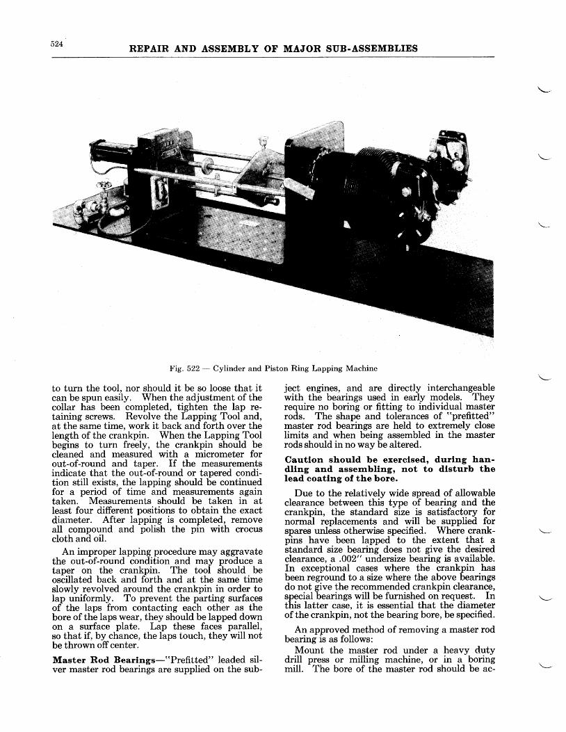
524 REPAIR AND ASSEMBLY OF MAJOR SUB.ASSEMBLIES
Fig. 522 - Cylinder and
to turn the tool, nor should it be so loose that itcan be spun easily. When the adjustment of thecollar has been completed, tighten the lap re-taining screws. Revolve the Lapping Tool and,at the same time, work it back and forth over theIength of the crankpin. When the Lapping Toolbegins to turn freely, the crankpin should becleaned and measured with a micrometer forout-of-round and taper. If the measurementsindicate that the out-of-round or tapered condi-tion still exists, the lapping should be continuedfor a period of time and measurements againtaken. Measurements should be taken in atIeast four different positions to obtain the exactdiaineter. After lapping is completed, removeall compound and polish the pin with crocuscloth and oil.
An improper lapping procedure may aggravatethe out-of-round condition and may produce ataper on the crankpin. The tool should beoscillated back and forth and at the same timeslowly revolved around the crankpin in order toIap uniformly. To prevent the parting surfacesof the laps from contacting each other as thebore of the laps wear, they should be lapped downon a surface plate. Lap these faces parallel,so that il bV chance, the laps touch, they will notbe thrown offcenter.
Master Rod Bearlngs-"Prefitted" leaded sil-ver master rod bearings are supplied on the sub-
Piston Ring Lapping Machine
ject engines, and are directly interchangeablewith the bearings used in early models. Theyrequire no boring or fitting to individual masterrods. The shape and tolerances of "prefitted"
master rod bearings are held to extremely closelimits and when being assembled in the masterrods should in no way be altered.
Cautlon should be exerclsed, durlng han-dllng and assernblltg, not to dlsturb theIead coatlng of the bore.
Due to the relatively wide spread of allowableclearance between this type of bearing and thecrankpin, the standard size is satisfactory fornormal replacements and will be supplied forspares unless otherwise specified. Where crank-pins have been lapped to the extent that astandard size bearing does not give the desiredclearance, a .002" undersize bearing is available.In exceptional cases where the crankpin hasbeen reground to a size where the above bearingsdo not give the recommended crankpin clearance,special bearings will be furnished on request. Inthis latter case, it is essential that the diameterof the crankpin, not the bearing bore, be specified.
An approved method of removing a master rodbearing is as follows:
Mount the master rod under a heavy dutydrill press or milling machine, or in a boringmill. The bore of the master rod should be ac-
525REPAIR AND ASSEMBLY OF MAJOR SUB.ASSEMBLIES
curately centered by the use of a dial indicator.Using an eccentric boring tool, bore out themaster rod bearing until only a thin shell re-mains, using great care not to cut into the bore ofthe master rod, itself. 'fhe bearing can be re-moved from the master rod by hand, or by tap-ping it lightly, after it has been reduced to a thinshell.
An alternate method of removing a master rodbearing is to make two cuts in the bearing aboutrf" apart and just deep enough to cut into thesteel back of the bearing.
Caution-Extreme care must be exercised notto cut into or damage the master rod.
Remove the small section, then collapse andremove the remainder of the bearing.
With the bearing removed, the bore of themaster rod should be measured. It is well toreinstall the knuckle pins in their holes as thepress fit of the pins is apt to affect the rod boremeasurements slightly. If enlarged so that anew standard size bearing will not give the properfit, the master rod should be reground to thenearest oversize. This is normally a factory joband rods should be returned to the United Air-ports Division, Rentschler Field, East Hartford,Connecticut, for reoperation.
The bore of the master rod should be magna-fluxed whenever a bearing is removed. It isrecommended that the bearing be removed andthe rod bore magnafluxed at about 2500 hourswhether or not the bearing requires replacement.See Chapter IV for nrethod of Magnaflux In-spection.
To install a new bearing, first heat the masterrod in an oil bath to 425o F'.-450o F., (218' C.-232 C.) preferably keeping it to the higher limit.Next, put the bearing in position on the MasterRod Bearing Assembly Arbor. It is well to put apiece of paper between the arbor and the bearingto protect the soft lead surface of the latter.Tighten the handle lightly to avoid difficulty inremoving it after the heat expands the bearing,and chili both the bearing and the arbor with dryice (COr). The bearing should be assembledwith the flange at the rear side of the master rod.After heating for twenty minutes, remove therod from the tank and allow the surplus oil todrain from it.
Quickly press in the new bearing by hand (seeFig. 523). Due to the length of the bearing andits tightness in the rod, it is important that thebearing be pressed in as rapidly as possible. Thebearing must be started straight with the slotin the flange perfectly aligned with the lug on themaster rod, and pressed home so that the flangeof the bearing seats firmly against the face of themaster rod. After the master rod has cooleddown to approximately room temperature, putthe master rod and bearing under an arbor press
and, using the same arbor as for installing thebearing, press the flange of the bearing againstthe master rod. This is necessary due to thefact that when the bearing cools there will be aslight clearance between the bearing flange andthe master rod.
Knuckle Ptrrs-At overhaul, knuckle pins andknuckle pin holes should be cleaned up andpolished. All traces of galling should be removedfrom the knuckle pin holes. Any score markson tlrg pins and holes should be cleaned up bypolishing off the high areas enough to obtainan even surface. Mount the knuckle pins in aIathe and polish with crocus cloth and oil. Theholes in the master rod may be cleaned ,rp with aflexible shaft polisher, or with crocus cloth andoil.
The cleaning and polishing of knuckle pins andknuckle pin holes is likely to affect the fit of thepins in the holes. The fit of each knuckle pinin the master rod should, therefore, be chec[edafter these operations have been completed.Measurements of the pins should be made with amicrometer and of the holes with a telescopicgage.
Knuckle pins and knuckle pin holes are gradedand marked with relation to their sizes. Eachknuckle pin and each hole in the master rod has aletter designation. A, B, and C designatestandard size knuckle pins, and D, E, and F areused where oversize pins are necessary to main-tain the desired fits. The sizes varv in steps of.0003". The knuckle pins and knuckle pin holesshould be of the same classification size. If it isfound that one end of a knuckle pin hole variesin classification size from the opposite end, thediameter of the smaller should be increased sothat the classification of both ends is the same.When the holes vary by one or two sizes, thismay be accomplished by lapping; otherwise theholes should be honed. The number and classi-fication sizes should be etched on both the pinand the master rod. When classification sizesare changed the etched letter should also bechanged.
Replacement knuckle pins for Wasp andHornet qngines are now made from nitralloysteel. These pins are directly interchangeablewith_ the previous type and may be identified bythe Number "249" stamped on one end.
Replacement.l<nuckle pins for the Wasp. Jr.engines are available in either chrome vanadiumor nitralloy steel.
Cautlon-If it is desired to change fromchrome vanadium to nitralloy knuckle pinsit is important that the crankshaft be properlybalanced. Refer to "Nitralloy Knuckle Pins",Chapter XVIII, "Miscellaneous Conversions".
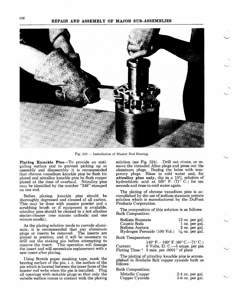
526REPAIR AND ASSEMBLY OF MAJOR SUB.ASSEMBLIES
Fig. 523 - Installation
Platlng Knuckle Plns-To provide an anti-galling surface and to prevent picking up atassembly and disassembly it is recommendedthat chrome vanadium knuckle pins be flash tinplated and nitralloy knuckle pins be flash copperplated at the time of overhaul. Nitralloy pinsmay be identified by the number "249" stampedon one end.
Before plating, knuckle pins shoutd bethoroughly degreased and cleaned of all carbon.This may be done with pumice powder and ascrubbing brush or if equipment is available,nitralloy pins should be cleaned in a hot alkalineelectro-cleaner (one minute cathodic and oneminute anodic).
As the plating solution tends to corrode alumi-num, it is recommended that any aluminumplugs or inserts be removed. The inserts arepinned in position, and it will be necessary todrill out the staking pin before attempting toremove the insert. This operation will damagethe insert and will necessitate replacement with anew insert after plating.
Using Scotch paper masking tape, mask thebearing surface of the pin, i. e. the surface of thepin which is located between the inner faces of themaster rod webs when the pin is installed. Plugall openings with suitable plugs so that only theoutside surface comes in contact with the plating
of Master Rod Bearing
solution (see Fig. 524). Drill out rivets, or re-move the threaded Allen plugs and press out thealuminum plugs. Replug the holes with tem-porary plugs. Rinse in cold water and, fornltralloy plns only, dip in a L\/o solution ofhydrochloric acid at 160' F. (71" C.) for tenseconds and rinse in cold water again.
The plating of chrome vanadium pins is ac-complished by the use of sodium stannate acetatesolution which is manufactured bv the DuPontProducts Corporation.
The composition of this solution is as follows:Bath Composition:
Sodium StannateCaustic SodaSodium AcetateHydrogen Peroxide
Bath Temperature:140o F.-160" F. (60 'c . -71 'C.)
Cunent: 6 Volts, D. C.-5 amps. per pinPlating Time: * 3 min. per .0001" of plate
The plating of nitralloy knuckle pins is accom-plished in Rochelle Salt copper cyanide bath asfollows:Bath Composition:
Metallic CopperCopper Cyanide
L2 oz. per gal.1 oz. per gal.2 oz. per gal.
(100 Vot.) Xo oz.per gal.
2-4 oz. per gal.3-6 oz. per gal.
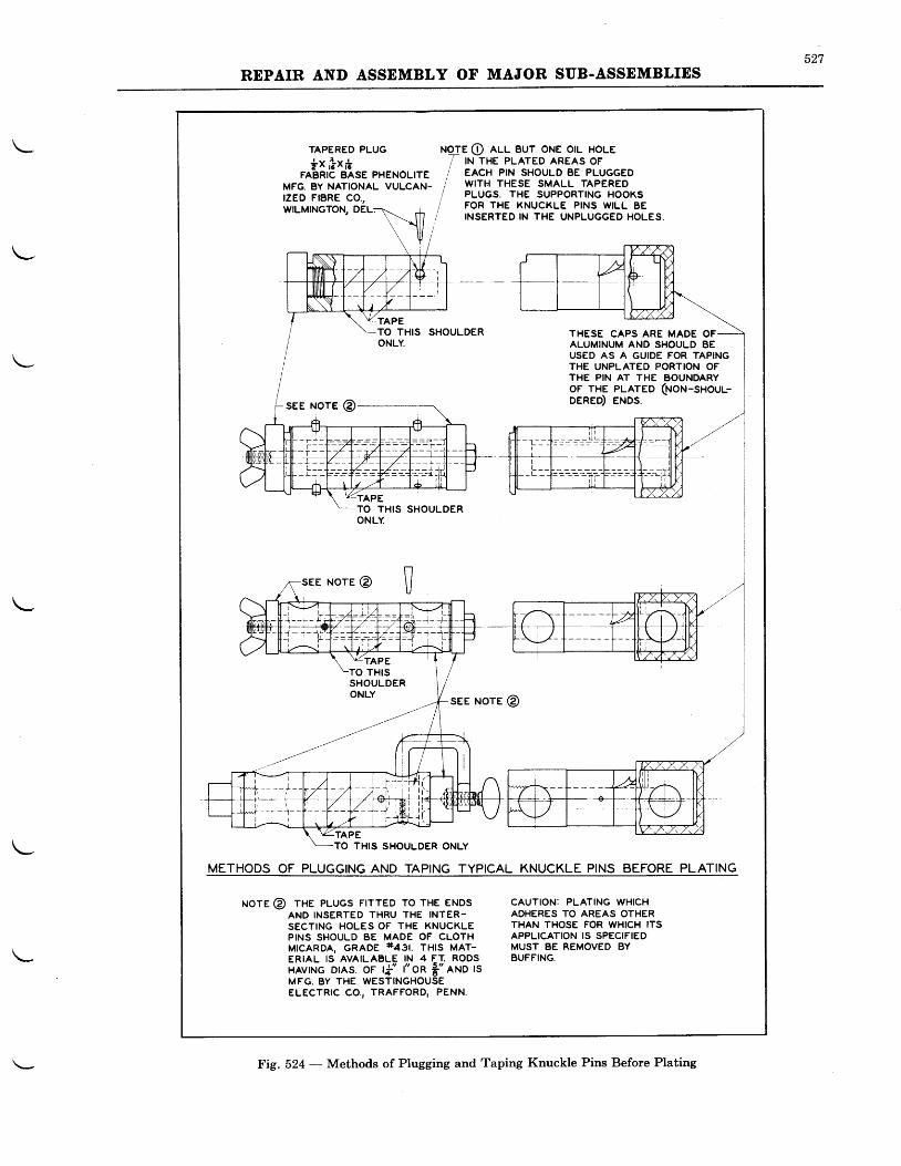
527REPAIR AND ASSEMBLY OF MAJOR SUB.ASSEMBLIES
THESE CAPS ARE MADE OFALUMINUM AND SHOULD BEUSED AS A GUIDE FOR TAPINGTHE UNPLATEO PORTION OFTHE PIN AT THE BOUNDARYoF THE PLATED (NoN-snouu-DERED) ENDS.
METHODS OF PLUGGING AND TAPING TYPICAL KNUCKLE PINS BEFORE PLATING
uore @ THE PLUGS FlrrED To rHE ENDSAND INSERTED THRU THE INTER.SECTING HOLES OF THE KNUCKLEPINS SHOULD BE MADE OF CLOTHM|CARDA, GRADE t+agt. tnts uet-ERIAL IS AVAILABLE IN 4 ET. RODSHAvTNG DtAs. oF t{' t" oR $" eruo tsMFG. BY THE WESTINGHOUSEELECTRTC CO., TRAFFORD, PENN.
CAUTION: PLATING WHICHADHERES TO AREAS OTHERTHAN THOSE FOR WHICH ITSAPPLICATION IS SPECIFIEDMUST BE REMOVED BYBUFFING.
TAPETHIS
see ruore @
Fig. 524 - Methods of Plugging and Taping Knuckle Pins Before Plating
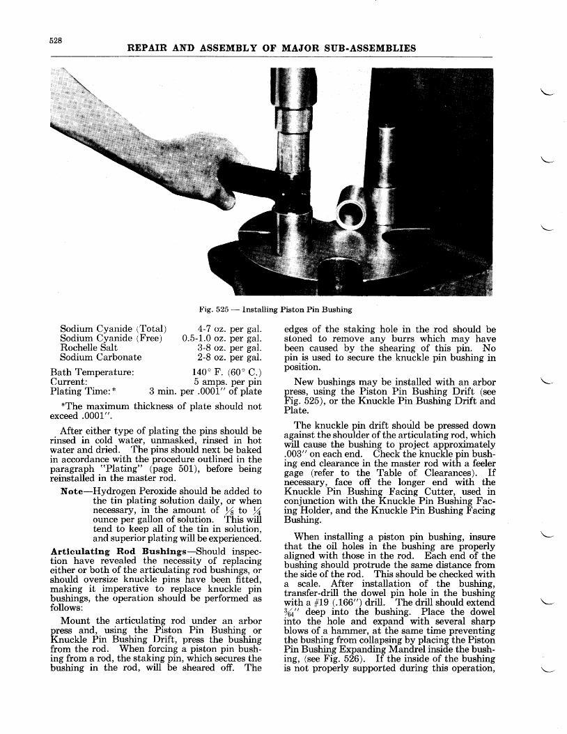
528REPAIR AND ASSEMBLY OF MAJOR SUB.ASSEMBLIES
Fig. 525 _- Installing Piston Pin Bushing
Sodium Cyanide lTotal) 4-7 oz.Sodium Cyanide (Free) 0.5-1.0 oz.Rochelle SaIt 3-8 oz.Sodium Carbonate 2-8 oz.
per gal.per gal.per gal.per gal.
Bath Temperature: 140" F. (60" C.)Current: 5 amps. per pinPlating Time: x 3 min. per .0001" of plate
*The maximum thickness of plate should notexceed .0001".
After either type of plating the pins should berinsed in cold water, unmasked, rinsed in hotwater and dried. The pins should next be bakedin accordance with the procedure outlined in theparagraph "Plating" (page 501), before beingreinstalled in the master rod.
Note-Hydrogen Peroxide should be added tothe tin plating solution daily, or whennecessary, in the amount of /s to %ounce per gallon of solution. 'lhis willtend to keep all of the tin in solution,and superior plating will be experienced.
Artleulatlng Rod Bushlngs-Should inspec-tion have revealed the necessity of replacingeither or both of the articulating rod bushings, orshould oversize knuckle pins have been fitted,making it imperative to replace knuckle pinbushings, the operation should be performed asfollows:
Mount the articulating rod under an arborpress and, using the Piston Pin Bushing orKnuckle Pin Bushittg Drift, press the bushingfrom the rod. When forcing a piston pin bush-ing from a rod, the staking pin, which secures thebushing in the rod, will be sheared off. The
edges of the staking hole in the rod should bestoned to remove any burrs which may havebeen caused by the shearing of this pin. Nopin is used to secure the knuckle pin bushing inposition.
New bushings may be installed with an arborpress, using the Piston Pin Bushing Drift (seeFig. 525), or the Knuckle Pin Bushing Drift andPlate.
The knuckle pin drift shotild be pressed downagainst the shoulder of the articulating rod, whichwill cause the bushing to project approximately.003" on each end. Check the knuckle pin bush-ing end clearance in the master rod with a feelergage (refer to the Table of Clearances). Ifnecessary, face off the longer end with theKnuckle Pin Bushing Facing Cutter, used inconjunction with the Knuckle Pin Bushing Fac-ing Holder, and the Knuckle Pin Bushing FacingBushing.
When installing a piston pin bushing, insurethat the oil holes in the bushing are properlyaligned with those in the rod. Each end of thebushing should protrude the same distance fromthe side of the rod. This should be checked witha scale. After installation of the bushing,transfer-drill the dowel pin hole in the bushingwith a #t9 (.166") drill. The drill should extend%t" deep into the bushing. Place the dowelinto the hole and expand with several sharpblows of a hammer, at the same time preventingthe bushing from collapsing by placing the PistonPin Bushing Expanding Mandrel inside the bush-ing, (see Fig. 526). If the inside of the bushingis not properly supported during this operation,
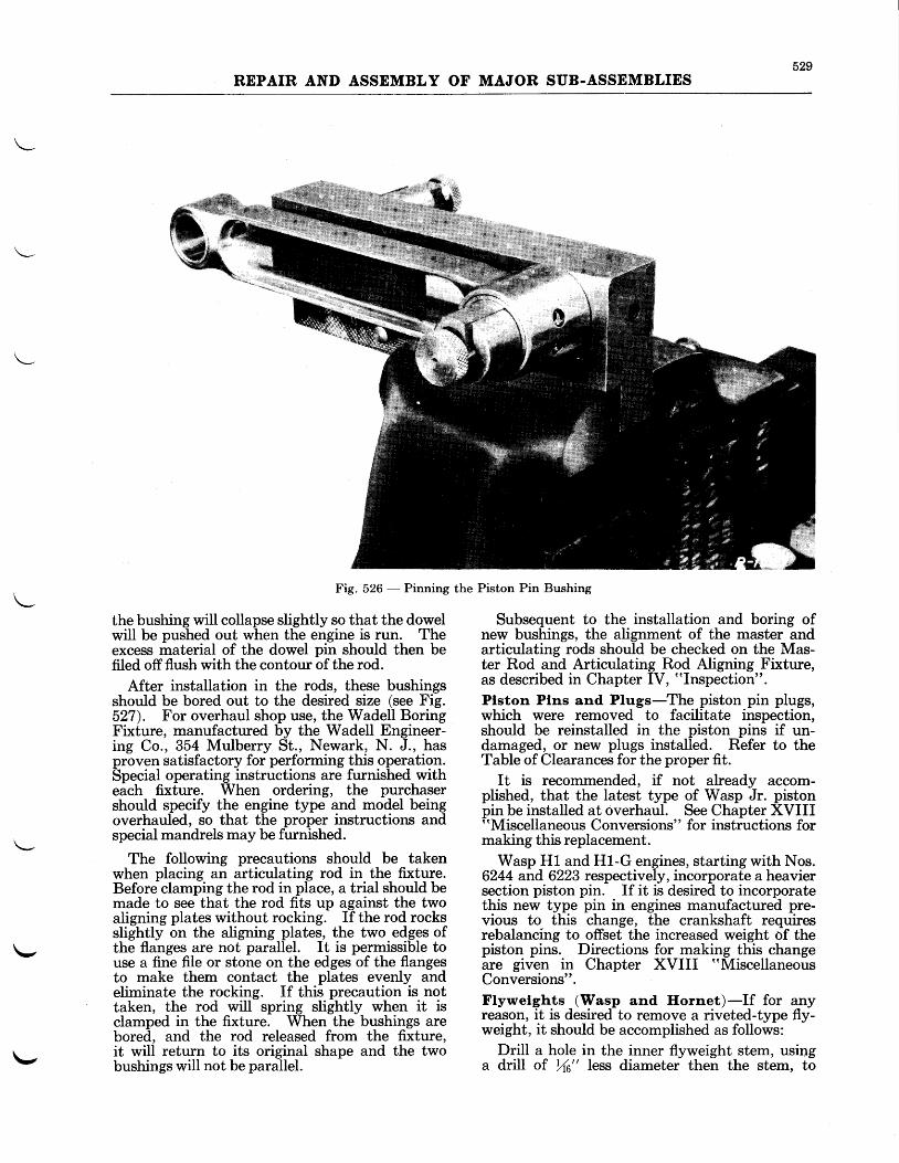
529REPAIR AND ASSEMBLY OF MAJOR SUB.ASSEMBLIES
\-,
Fig. 526 - Pinning the
the bushing will collapse slightly so that the dowelwill be pushed out when the engine is run. Theexcess material of the dowel pin should then befiled offflush with the contour of the rod.
After installation in the rods, these bushingsshould be bored out to the desired size (see Fig.527). For overhaul shop use, the Wadell BoringFixture, manufactured by the Wadell Engineer-ing Co., 354 Mulbemy St., Newark, N. J., hasproven satisfactory for performing this operation.Special operating instructions are furnished witheach fixture. When ordering, the purchasershould specify the engine type and model beingoverhauled, so that the proper instructions andspecial mandrels may be furnished.
The following precautions should be takenwhen placing an articulating rod in the fixture.Before clamping the rod in place, a trial should bemade to see that the rod fits up against the twoaligning plates without rocking. If the rod rocksslightly on the aligning plates, the two edges ofthe flanges are not parallel. It is permissible touse a fine file or stone on the edges of the flangesto make them contact the plates evenly andeliminate the rocking. If this precaution is nottaken, the rod will spring slightly when it isclamped in the fixture. When the bushings arebored, and the rod released from the fixture,it will return to its original shape and the twobushings will not be parallel.
Piston Pin Bushing
Subsequent to the installation and boring ofnew bushings, the alignment of the master andarticulating rods should be checked on the Mas-ter Rod and Articulating Rod Aligning Fixture,as described in Chapter IV, "Inspection".
Plston Plns and Plugs-The piston pin plugs,which were removed to facilitate inspection,should be reinstalled in the piston pins if un-damaged, or new plugs install-ed. R-efer to theTable of Clearances for the proper fit.
It is recommended, if not already accom-plished, that the latest type of Wasp Jr. pistonpin be installed at overhaul. See Chapter XVIII"Miscellaneous Conversions" for instructions formaking this replacement.
Wasp H1 and H1-G engines, starting with Nos.6244 and 6223 respectively, incorporate a heaviersection piston pin. If it is desired to incorporatethis new type pin in engines manufactured pre-vious to this change, the crankshaft requiresrebalancing to offset the increased weight of thepiston pins.. Directions for qgLi$-!his-changeare given in Chapter XVIII "Miscellaneous
Conversions".Flywelghts (Wasp and Hornet)-If for anyreason, it is desired to remove a riveted-type fly-weight, it should be accomplished as follows:
Drill a hole in the inner flyweight stem, usinga drill of 14" less diameter then the stem, to\-
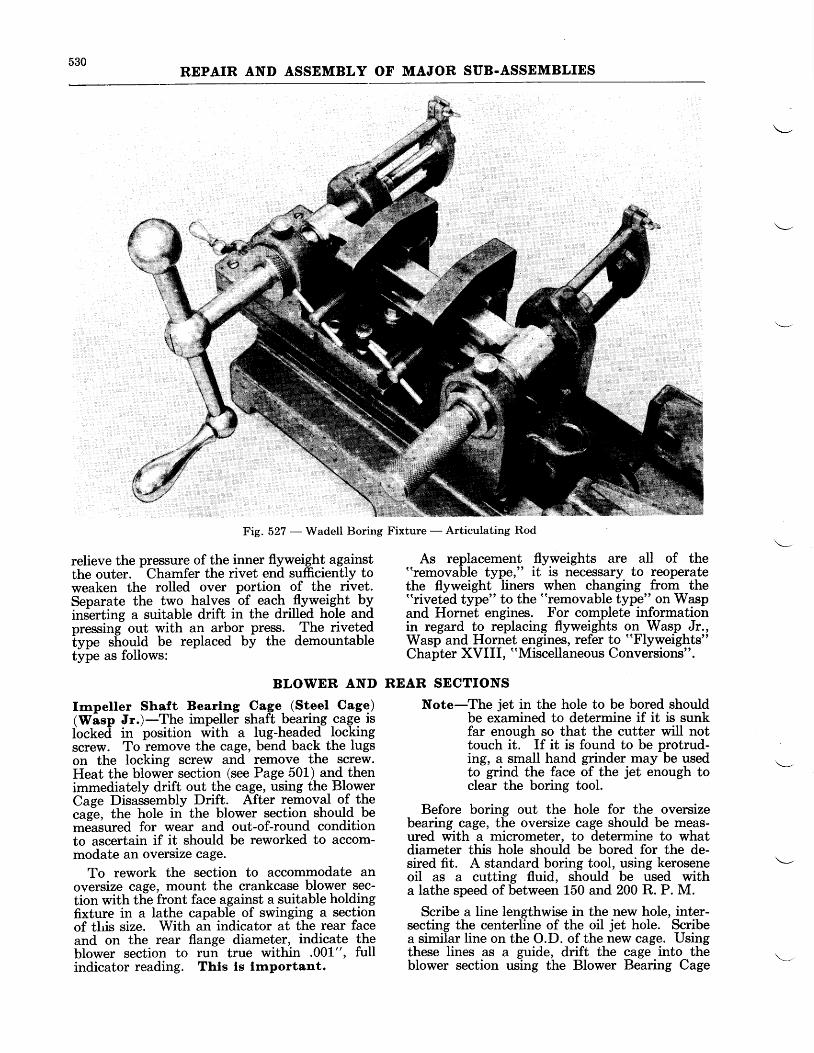
530REPAIR AND ASSEMBLY OF MAJOR SUB.ASSEMBLIES
Fig. 527 - Wadell Boring Fixture - Articulating Rod
relieve the pressure of the inner flyweight againstthe outer.
- Chamfer the rivet end sufficiently to
weaken the rolled over portion of the rivet.Separate the two halves of each flyweight byins-erting a suitable drift in the drilled hole andoressing out with an arbor press. The rivetedtyp" should be replaced by the demountabletype as follows:
As replacement flyweights are all of the"removable type:' it is necessary to reoperatethe flyweight liners when changing from the"riveted type" to the "removable type" on Waspand Hornet engines. For complete informationin regard to replacing flyweights on Wasp Jr.,Wasp and Hornet engines, refer to "Flyweights"
Chapter XVIII, "Miscellaneous Conversions".
BLOWER AND REAR SECTIONS
Irnpeller Shaft Bearlng Cage (Steel Cage)(Wasp Jr.)-The impeller shaft bearing cage islocked in
'position with a lug-headed loc\ing
screw. To remove the cage, bend back the lugson the locking screw and remove the screw.Heat the blower section (see Page 501) and thenimmediately drift out the cage, using the BlowerCage Disassembly Drift. After removal of thecaie, the hole in the blower section should bemdasured for wear and out-of-round conditionto ascertain if it should be reworked to accom-modate an oversize cage.
To rework the section to accommodate anoversize cage, mount the crankcase blower sec-tion with the front face against a suitable holdingfixture in a lathe capable of swinging a sectionof tlis size. With an indicator at the rear faceand on the rear flange diameter, indicate theblower section to run true within .001-", fullindicator reading. Thts ls funportant.
Note-The jet in the hole to be bored shouldbe examined to determine if it is sunkfar enough so that the cutter will nottouch it. If it is found to be protrud-ing, a small hand grinder may be usedto grind the face of the jet enough toclear the boring tool.
Before boring out the hole for the oversizebearing cage, the oversize cage should be meas-ured with a micrometer, to determine to whatdiameter this hole should be bored for the de-sired fit. A standard boring tool, using keroseneoil as a cutting fluid, should be used witha lathe speed of between 150 and 200 R. P. M.
Scribe a line lengthwise in the new hole, inter-secting the centerline of the oil jet hole. Scribea similar line on the O.D. of the new cage. Usingthese lines as a guide, drift the cage into theblower section using the Blower Bearing Cage
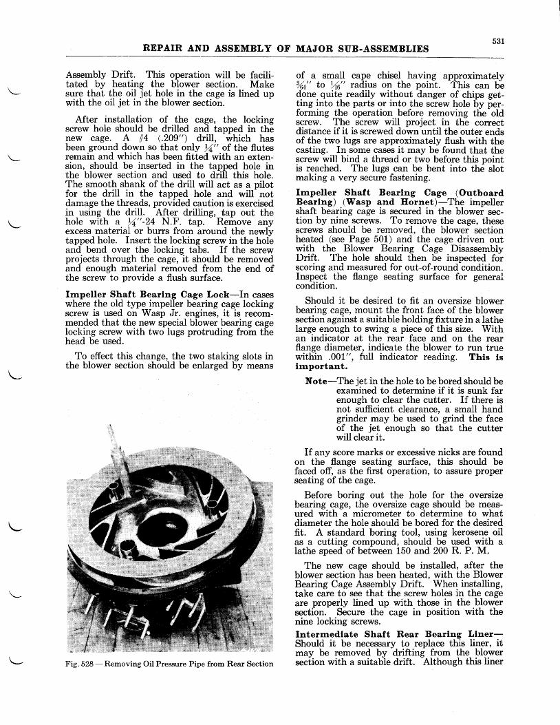
531REPAIR AND ASSEMBLY OF MAJOR SUB-ASSEMBLIES
Assembly Drift. This operation will be facili-tated by heating the blower section. Makesure that the oil jet hole in the cage is lined upwith the oil jet in the blower section.
After installation of the cage, the lockingscrew hole should be drilled and tapped in thenew cage. A #4 (.209") drill, which hasbeen ground down so that only rA" of the flutesremain and which has been fitted with an exten-sion, should be inserted in the tapped hole inthe blower section and used to drill this hole.The smooth shank of the drill will act as a pilotfor the drill in the tapped hole and will notdamage the threads, provided caution is exercisedin using the drill. After drilling, tap out thehole with a rZ" -24 N.F. tap. Remove anyexcess material or burrs from around the newlytapped hole. Insert the locking screw in the holeand bend over the locking tabs. If the screwprojects through the cage, it should be removedand enough material removed from the end ofthe screw to provide a flush surface.
knpeller Shaft Bearlng Cage Lock-In caseswhere the old type impeller bearing cage lockingscrew is used on Wasp Jr. engines, it is recom-mended that the new special blower bearing cagelocking screw with two lugs protruding from thehead be used.
To effect this change, the two staking slots inthe blower section should be enlarged by means
of a small cape chisel having approximatelys4nt' to r/16" radius on the point. 'fhis can bedone quite readily without danger of chips get-ting into the parts or into the screw hole by per-forming the operation before removing the-oldscrew. The screw will project in the correctdistance if it is screwed down until the outer endsof the two lugs are approximately flush with thecasting. In some cases it may be found that thescrew will bind a thread or two before this pointis reached. The lugs can be bent into the slotmaking a very secure fastening.
Irnpeller Shaft Bearlng Cage (OutboardBearing) (Wasp and Hornet)-The impellershaft bearing cage is secured in the blower sec-tion by nine screws. To remove the cage, thesescrews should be removed, the blower sectionheated (see Page 501) and the cage driven outwith the Blower Bearing Cage DisassemblyDrift. The hole should then be inspected forscoring and measured for out-of-round condition.Inspect the flange seating surface for generalcondition.
Should it be desired to fit an oversize blowerbearing cage, mount the front face of the blowersection against a suitable holding fixture in a latheIarge enough to swing a piece of this size. Withan indicator at the rear face and on the rearflange diameter, indicate the blower to run truewithin .001", full indicator reading. This lsirnportant.
Note-The jet in the hole to be bored should beexamined to determine if it is sunk farenough to clear the cutter. If there isnot sufficient clearance, a small handgrinder may be used to grind the faceof the jet enough so that the cutterwill clear it.
If any score marks or excessive nicks are foundon the flange seating surface, this should befaced off, as the first operation, to assure properseating of the cage.
Before boring out the hole for the oversizebearing cage, the oversize cage should be meas-ured with a micrometer to determine to whatdiameter the hole should be bored for the desiredfit. A standard boring tool, using kerosene oilas a cutting compound, should be used with alathe speed of between 150 and 200 R. P. M.
The new cage should be installed, after theblower section has been heated, with the BlowerBearing Cage Assembly Drift. When installing,take care to see that the screw holes in the cageare properly lined up with those in the blowersection. Secure the cage in position with thenine locking screws.Interrnedlate Shaft Rear Bearlng Llner-Should it be necessary to replace this liner, itmay be removed by drifting from the blowersection with a suitable drift. Although this linerFig. 528 -Removing Oil Pressure Pipe from Rear Section
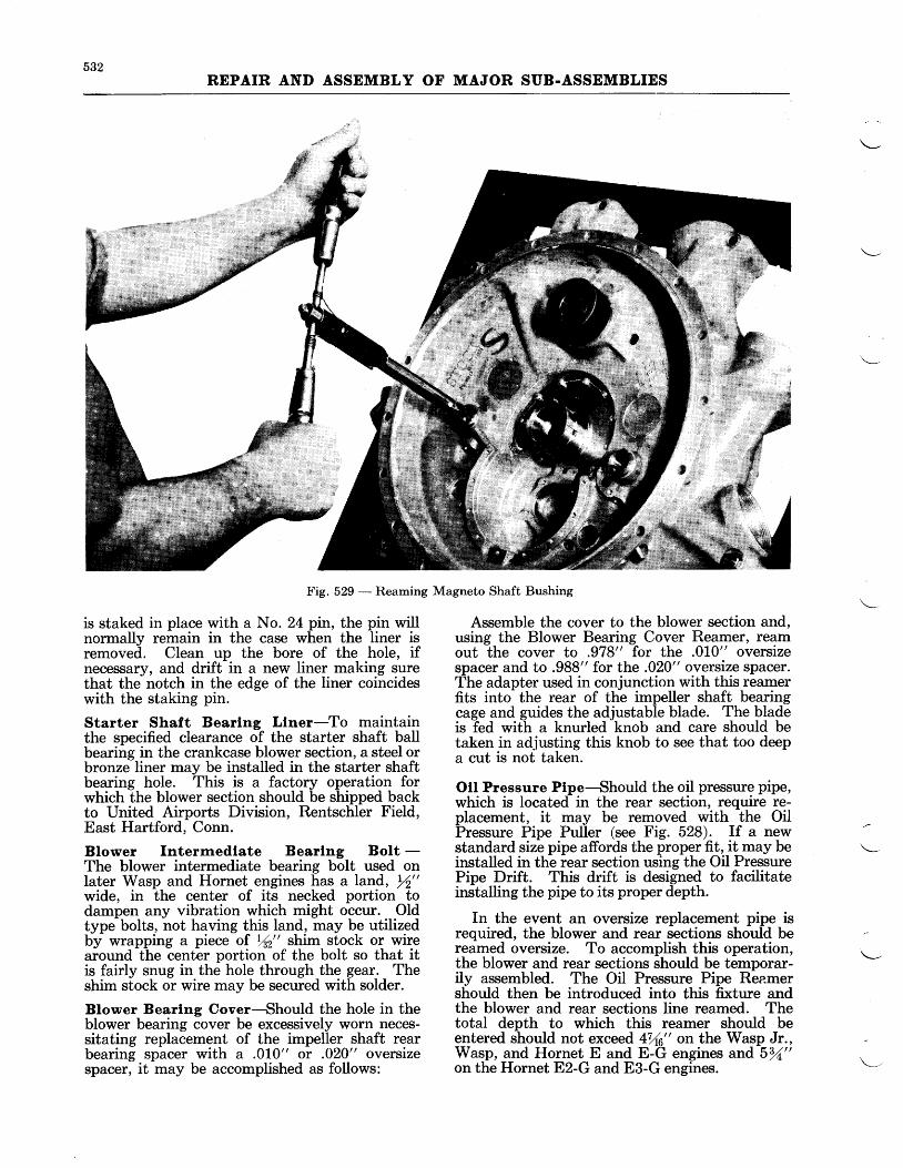
532REPAIR AND ASSEMBLY OF MAJOR SUB.ASSEMBLIES
Fig. 529 - Reaming Magneto Shaft Bushing
is staked in place with a No. 24 pin, the pin willnormally remain in the case when the liner isremoved. Clean up the bore of the hole, ifnecessary, and drift in a new liner making surethat the notch in the edge of the liner coincideswith the staking pin.
Starter Shaft Bearlng Liner-To maintainthe specified clearance of the starter shaft ballbearing in the crankcase blower section, a steel orbronze liner may be installed in the starter shaftbearing hole. This is a factory operation forwhich the blower section should be shipped backto United Airports Division, Rentschler Field,East Hartford, Conn.
Blower Intermedlate Bearlng Bolt -The blower intermediate bearing bolt used onlater Wasp and Hornet engines has a land, \f"wide, in the center of its necked portion todampen any vibration which might occur. Oldtype bolts, not having this land, may be utilizedby wrapping a piece of %2" shim stock or wirearound the center portion of the bolt so that itis fairly snug in the hole through the gear. Theshim stock or wire may be secured with solder.
Blower Bearlng Cover-Should the hole in theblower bearing cover be excessively worn neces-sitating replacement of the impeller shaft rearbearing spacer with a .010" or .020" oversizespacer, it may be accomplished as follows:
Assemble the cover to the blower section and,using the Blower Bearing Cover Reamer, reamout the cover to .978" for the .010" oversizespacer and to .988" for the .020" oversize spacer.The adapter used in conjunction with this reamerfits into the rear of the impeller shaft bearingcage and guides the adjustable blade. The bladeis fed with a knurled knob and care should betaken in adjusting this knob to see that too deepa cut is not taken.
Oll Pressure Ptpe-Should the oil pressure pipe,which is located in the rear section, require re-placement, it may be removed with the OilPressure Pipe Puller (see Fig. 528). If a newstandard size pipe affords the proper fit, it may beinstalled in the rear section using the Oil PressurePipe Drift. This drift is designed to facilitateinstalling the pipe to its proper depth.
In the event an oversize replacement pipe isrequired, the blower and rear sections should bereamed oversize. To accomplish this operation,the blower and rear sections should be temporar-ily assembled. The Oil Pressure Pipe Reamershould then be introduced into this fixture andthe blower and rear sections line reamed. Thetotal depth to which this reamer should beentered should not exceed 416" on the Wasp Jr.,Wasp, and Hornet E and E-G engines and 531"on the Hornet Ez-G and E3-G engines.
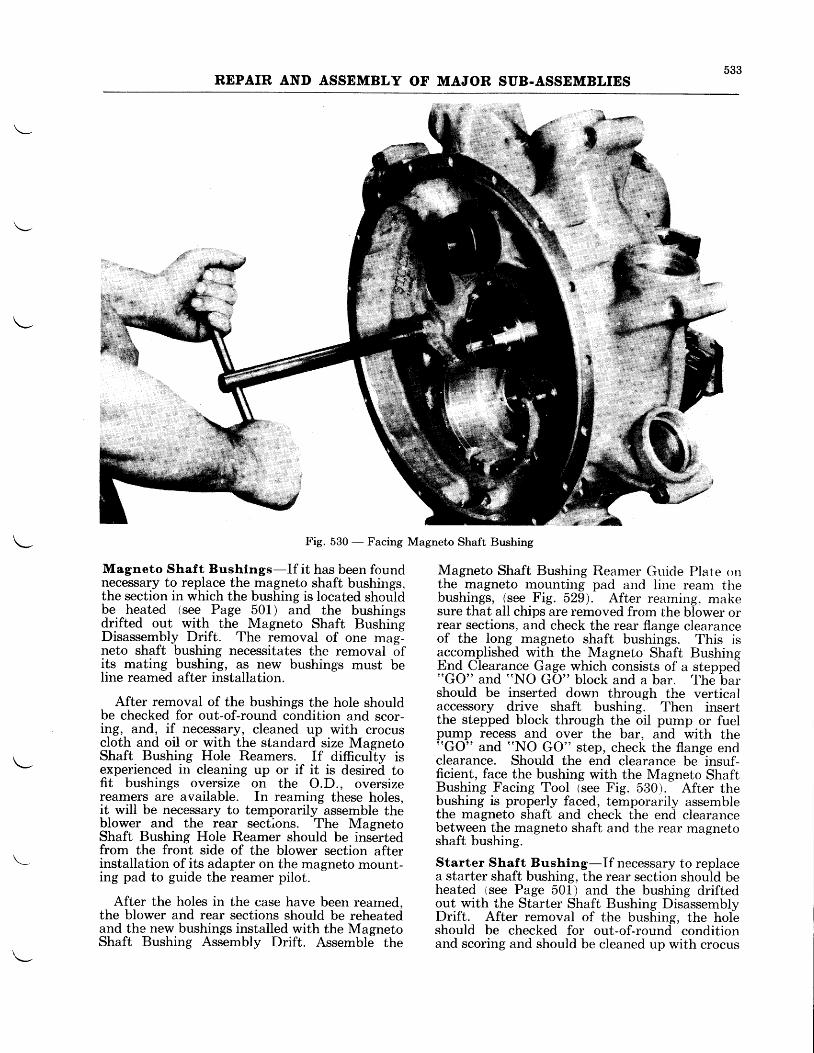
533REPAIR AND ASSEMBLY OF MAJOR SIIB.ASSEMBLIES
Fig. 530 - Facing Magneto Shaft Bushing
Magneto Shaf t Bushlngs-If it has been foundn€cessary to replace the magneto shaft bushings.the section in which the bushing is located shouldbe heated (see Page 501) and the bushingsdrifted out with the Magneto Shaft BushingDisassembly Drift. The removal of one mag-neto shaft bushing necessitates the removal ofits mating bushing, as new bushings must beline reamed after installation.
After removal of the bushings the hole shouldbe checked for out-of-round condition and scor-irg, and, if necessary, cleaned up with crocuscloth and oil or with the standard size MagnetoShaft Bushing HoIe Reamers. If difficully isexperienced irr cleaning up or if it is desired tofit bushings oversize on the O.D., oversizereamers are available. In reaming these holes,it will be necessary to temporarily assemble theblower and the rear sections. The MagnetoShaft Bushing Hole Reamer should be insertedfrom the front side of the blower section afterinstallation of its adapter on the magneto mount-ing pad to guide the reamer pilot.
After the holes in the case have been reamed,the blower and rear sections should be reheatedand the new bushings installed with the MagnetoShaft Bushing Assembly Drift. Assemble the
Magneto Shaft Bushing Reamer Guide Plate onthe magneto mounting pad and iine ream thebushings, (see Fig. 529). After reaming. makesure that all chips are removed from the blower orrear sections, and check the rear flange clearanceof the long magneto shaft bushings. This isaccomplished wlth the Magneto Shaft BushingEnd Clearance Gage which consists of a stepped"GO" and "NO GO" block and a bar. The barshould be inserted down through the verticalaccessory drive shaft bushing. Then insertthe stepped block through the oil pump or fuelpump recess and over the bar, and with the((GO" and "NO GO" step, check the flange endclearance. Should the end clearance be insuf-ficient, face the bushing with the Magneto ShaftBushing Facing Tool (see Fig. 530). After thebushing is properly faced, temporarily assemblethe magneto shaft and check the end clearancebetween the magneto shaft and the rear magnetoshaft bushing.
Starter Shaft Bushing-If necessary to replacea starter shaft bushing, the rear section should beheated tsee Page 501) and the bushing driftedout with the Starter Shaft Bushing DisassemblyDrift. After removal of the bushing, the holeshould be checked for out-of-round conditionand scoring and should be cleaned up with crocus
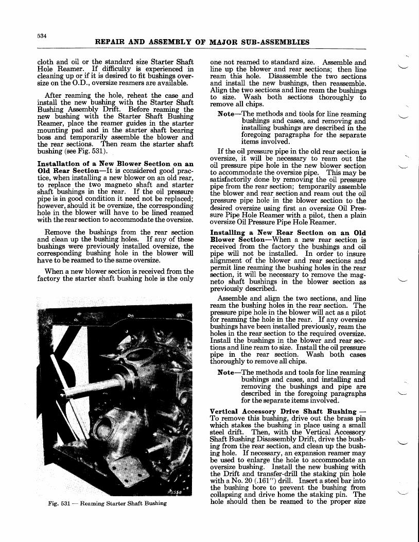
534REPAIR AND ASSEMBLY OF MAJOR SUB-ASSEMBLIES
cloth and oil or the standard size Starter ShaftHole Reamer. If difficulty is experienced incleaning up or if it is desired to fit bushings over-size on the O.D., oversize reamers are available.
After reaming the hole, reheat the case andinstall the new bushing with the Starter ShaftBushing Assembly Drift. Before reaming thenew bushing with the Starter Shaft BushingReamer, place the reamer guides in the startermounting pad and in the starter shaft bearingboss and temporarily assemble the blower andthe rear sections. Then ream the starter shaftbushing (see Fig. 531).
Installatlon of a New Blower Sectlon on anOld Rear Section-It is considered good prac-tice, when installing a new blower on an old rear,to replace the two magneto shaft and startershaft bushings in the rear. If the oil pressurepipe is in good condition it need not be replaced;however, should it be oversize, the correspondinghole in the blower will have to be lined reamedwith the rear section to accommodate the oversize.
Remove the bushings from the rear sectionand clean up the bushing holes. If any of thesebushings were previously installed oversize, thecorresponding bushing hole in the blower willhave to be reamed to the same oversize.
When a new blower section is received from thefactory the starter shaft bushing hole is the only
one not reamed to standard size. Assemble andline up the blower and rear sections; then lineream this hole. Disassemble the two sectionsand install the new bushings, then reassemble.Align the tw_o sgctions and line ream the bushingsto size. Wash both sections thorougtrly toremove all chips.
Note-The methods and tbols for line reamingbushings and cases, and removing andlinslalling bushings are described in theforegoing paragraphs for the separateitems involved.
If the oil pressure pipe in the old rear section isoversize, it will be necessary to ream out theoil pressure pipe hole in the new blower sectionto accommodate the oversize pipe. This may besatisfactorily done by removing the oil pressurepipe from the rear section; temporarily assemblethe blower and rear section and ream out the oilpressure pipe hole in the blower section to thedesired oversize using first an oversize Oil Pres-sure Pipe Hole Reamer with a pilot, then a plainoversize Oil Pressure Pipe Hole Reamer.
Installlng a New Rear Sectlon on an OtdBlower Sectlon-When a new rear section isreceived from the factory the bushings and oilpipe will not be installed. In order to insurealignment of the blower and rear sections andpermit line reaming the bushing holes in the rearsection, it *ill be necessary to remove the mag-neto shaft bushings in the blower section aspreviously described.
Assemble and align the two sections, and lineream the bushing holes in the rear section. Thepressure pipe hole in the blower will act as a pilotfor reaming the hole in the rear. If any oversizebushings have been installed previously, ream theholes in the rear section to the required oversize.Install the bushings in the blower and rear sec-tions and line ream to size. Install the oil pressurepipe in the rear section. Wash both casesthoroughly to remove all chips.
Note-The methods and tools for line reamingbushings and cases, and installing audremoving the bushings and pipe aredescribed in the foregoing paragraphsfor the separate items involved.
Vertlcal Accessory Drlve Shaft Bushlng -To remove this bushing, drive out the brass pinwhich stakes the bushing in place using a smallsteel drift. Then, with the Vertical AccessoryShaft Bushing Disassembly Drift, drive the bush-lng fro;n tbe rear section, and clean up the bush-ing hole. If necessary, an expansion reamer maybe used to enlarge the hole to accommodate anoversize bushing. Install the new bushing withthe Drift and transfer-drill the staking pin holewith a No. 20 (.t6L" ) drill. Insert a steel bar intothe bushing bore to prevent the bushing fromcollapsing and drive home the staking pin. Thehole should then be reamed to the proper sizeFig. 531 - Reaming Starter Shaft Bushing
535REPAIR AND ASSEIIIBLY OF MAJOR SUB.ASSEMBLIES
with the Vertical Accessory Drive Shaft Reamer.This reamer is used in conjunction with a pilotwhich is mounted on the gun synchronizermounting pad.
Vacuum. Purnp l)rlve Llner-The VacuumPump Drive Liner Puller should be used for re-moving this part from the engine. With a suita-ble drift, drive the new liner into the hole untilthe flange of the liner seats on the shoulder in thehole, taking care to press the liner down evenly.Cocking will prevent proper seating. To deter-mine if this liner has been properly bottomed,measure the distance from the flange of the linerto the face of the vacuum pump mounting padwith a depth gage. This depth should be .802"to .824".
Intake Alr Ternperature Therrnorneter In-terference-On Wasp Jr., Wasp, and Hornet Eand E-G engines on which the intake air tempera-ture is measured at the mixture duct of the rearsection, the diameter of the hole in the upper vaneof the mixture duct has been increased fromYta" to 2%2". In cases where this has not alreadyb,een accomplished, this hole should be enlarged.Use a 2yur r counterbore with a %0" pilot, suppbrt-ing the vane during this operation by means of awooden block placed between it and the nextlower vane. After boring, remove all sharpedges. Extreme care should be taken to removeall chips from the air intake passage.
Otl Pump-If inspection has revealed the neces-sity for replacement of any one section of the oilpump housing, it will be necessary to replace theentire housing assembiy. Scratches and burrsin any section of the housing, not serious enough
to cause rejection of the casting, should be re-moved with a small triarlsul?r scraper, as emeryshould not be used on aluminum. Where insuf-ficient clearance between t_he geqrs and housinghas caused the ggars to 4rb_ on the casting, thiscondition should be rectified by scraping enoughmaterial from the casting to Srlr" the
"specifi6d
clearance at this qoint, pro-viding lhe iubbingis not a result of some abnormal condition.Scratches and buns on the shafts should be re-moved by mounting the shaft in a polishing latheand - pplislring -wit-h ^elnety._ After polfuhing,check the fit of the shaft in the housing.
-
If necessary to replace idler shaft use a solidsteel drift that fits snugly into the hollow searshaft to shear the pin from the inside of the sliaft.Drift out the part of the pin that extendsthrough the gear on one side. Mount the gearand shaft in a drill press and drill out the remlin-iqg. put! of the qi4 to 1 deplh of,ap,proximately%a" inthe gear with a #31 (.120") drill-. The hol-etfrougb_the gear and sha& is used as a guide forthe driiligg operation. Remove the gear andclean up the pin holes.
Pratt and Whltney Valve Lubrleator (WaspJr. B an$ B2)-In order-to prevent delivery oTan excessive amount of oil to-the valve mec6an-ism, it is important that the clearance betweenthe lubricator gear plunger and the housing bemaintained within the specified limits. As o-ver-size plungersr are not available, excessive clear-ance will entail replacement of the housins. Incases where the angular end surface of thelubri-cator plunger shows signs of wear, it should belapped smooth. Wlqere signs of flaking are ob-served, the plunger should be renewed.
-
3. All gaskets, packings and oil seals should bereplaced at each overhaul.
4. A torque indicating wrench should beused when tightening the nuts which have recom-mended torques listed in the Appendix.
5. In all assembly operations refer to theTable of Clearances for the desired fit or clear-ance.
6. New safety wiring, tab washers, cotterpins, fiber nuts and palnuts should be installedwhere necessary. It is important that cotterpins and safety wire fit snugly in the holes forwhich they are intended. Always install thehead or loop end of the cotter pin to fit in thecastellation of the nut and not outside. Theends should be bent, one up and back over thestud or bolt end, and the other down flat againstthe hexagon flat ofthe nut.
ASSEMBLY OF MAJOR SUB.ASSEMBLIES
General-The assembly methods and procedureslisted below, although playing an important partin efficient engine overhaul, will not be specif-ically mentioned in the "Detail Instructions" ofthis Assembly Section and the Final AssemblyChapter which follow. Although these itemsmay seem of minor importance, the ultimatelife and performance of the engine may beseriously affected if they are slighted throughcarelessness or neglect.
1. During assembly operations, care shouldbe taken to prevent dirt, dust, cotter pins, safetywire, nuts, washers, and any other parts fromentering the engine. Suitable plugs and cover-ings to fit all openings should be improvised andused.
2. All bearing surfaces, anti-friction bearings,and movable parts should be thoroughly coatedwith oil.
536REPAIR AND ASSEMBLY OF ITIAJOR SUB.ASSEMBLIES
DETAIL INSTRUCTIONS
FRONT (Nose) SECTION-WASP JR.
Tappets and Rollers-Prior to the assembly oftappets and rollers in the front section, the tap-pets should be coated liberally with oil. ForWasp Jr. B and 82 engines insert the spring intothe tappet, slide the tappet into the guide, andsecure it in position with the combination tappetand tappet guide locking screw.
For the Wasp Jr. B3 engine, the rocker oilmanifold should be placed inside the front sectionand secured to the tappet guide bosses with theL8 combination locking screws. Then coat thetappets with oil and insert each in its respectiveguide.
Draining type tappets should be installed in thefollowing tappet guide locations: 1 In., 1 Ex.,21n. ,28x. ,3 Ex. , 8 In . , 9 In . , and 9 Ex.
After installation, the tappets should be de-pressed until roller pin hole clears the inner endof the tappet guide. Insert the roller in the tap-pet slot and slide the roller pin into position, mak-ing sure the ends of the roller pin are inside thetappet guide when the tappet is allowed to returnto its normal position.
FRONT (Nose) SECTION-WASP Hl
Propeller Otl Feed Plpe-Insert the propelleroil feed pipe through its hole in the front sectionand into the hole in the thrust bearing liner.
Governor Drlve Gear (Wasp Hl only)-Coatthe inside diameter of the governor drive gearbushing with oil and place the governor drivegear in position in its bushing. Secure in posi-tion with the locking ring.
Intermedlate Governor Drlve Gear (Wasp Elonly)-Place the intermediate governor ilrive
Front Breather Assembly (If Provlded)-Remove the cap flom the breather assembly dndinstall the assembly -in the- nose section, turningit by means of a lever inserted between thescrew bosses in the body of the breather. Installcap and secure it with the two screws.
Propeller Regulator Valve (If Provtded) -Prior to installation of the propeller regulatorvalve in the nose section on Wasp Jr. B ind 82e_ngr.lgs or the prgpeller oil stlnnly fttting on WaspJr. 83 engines, the pipe leading from the resula-tor valve boss to the thrust bearing liner strbuldbe installed.
If a new valve and shaft is to be installed in!h9 pTopellgr regulator valve, it should be lappedinto the valve seat with a fine lapping compound.After lapping make sure that all traces
-of the
compound are washed from the valve and seat.A +* pagkigs should be installed in the cover bytwisting in the direction of the thread until it isbottomed. Slide the shaft through the coverfrom the bottom and install the packing nut inthe cover. Install the lever on the outer end ofthe shaft and secure it in position with the taperpin. Fit the assembly in the case and secirrewith three nuts.
AND EORNET E (Dlreet Drlve)
gear il tbq intermediate-governor drive gear sup-port bushing. Assemble the pinion diive searon the end of the shaft and lock in position i'iththe washer and nut. Assemble the supportinside the front section and secure with ihreeretaining nuts.
Instructions for adjusting the backlash be-tween the intermediate governor drive gear andthe governor drive gear are contained under theheading "Intermediate Governor Drive GearBushing" in the Repair Section of this Chapter.
lropel[e.r Otl Feed ltp" (Eornet Engtnes)-Insert this pipe into the nose section and-into iheoil pipe hole in the fixed sear; then secure it inpgsition by screwing the nose section oil passageplug into the pipe hole.
Ptrlton_C"gg (tVasp Hl-G)-The pinion shafts,pinio3 shaf-t holes, pinion races, and pinion gearsare all numbered. When these parts are profertyassembled,- -the numbers of the various mitin!parts should correspond.
. Place the pjnion shafts in their proper holesin the rear half of the pinion cage ana phce the
FRONT sEcTIoN (Reductlon Gearlng and Houslng Assernbly)wasP El-G, HORNET E-G AND Ez-G
Flxed Gear-Install the fixed gear in the frontof the reduction gear housing and secure with thehold-down nuts and washers. For the WaspH1-G engine, the propeller oil feed pipe should bbinserted in the oil pipe hole in the gear, prior tothe assembly of the gear in the nose section.Secure in position with its hold-down clip afterthe fixed geax is in place.
When installing the fixed gear.on Hornet en-gines, see that the propeller oil feed pipe hole inthe gear is properly aligned with the hole in thehousing to permit subsequent installation of thepropeller oil feed pipe.
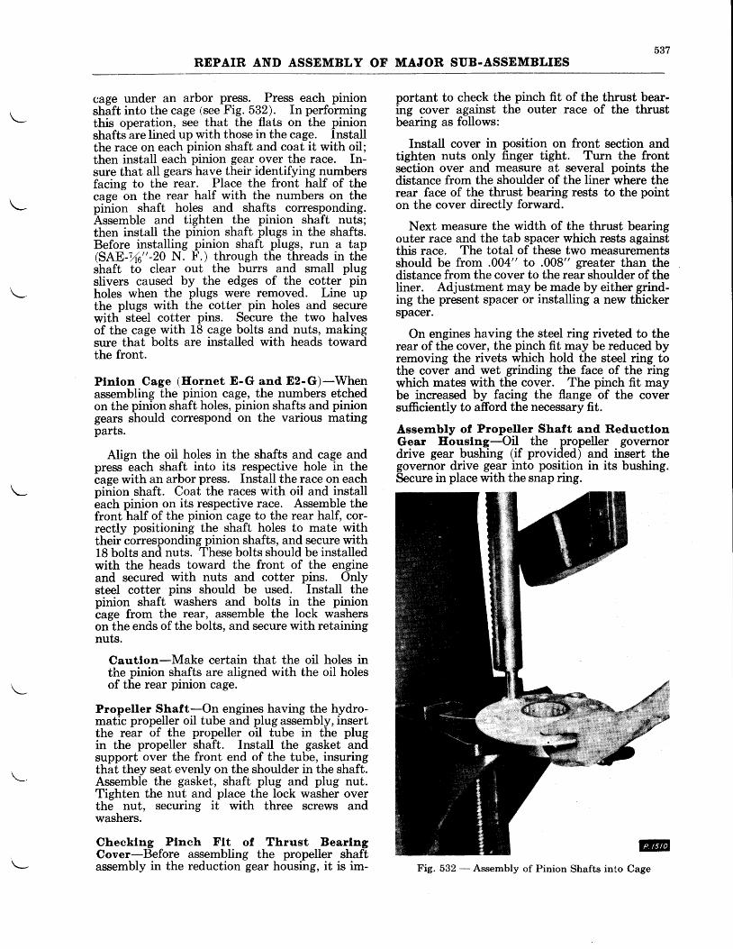
537REPAIR AND ASSEMBLY OF MAJOR SUB-ASSEMBLIES
cage under an arbor pJess. Press each pinionshaft into the cage (see Fig. 532). In performingthis operation, see that the flats on the pinionshafts are lined up with those in the cage. Installthe race on each pinion shaft and coat it with oil;then install each pinion gear over the race. In-sure that aII gears have their identifying numbersfacing to the rear. Place the front half of thecage on the rear half with the numbers on thepinion shaft holes and shafts corresponding.Assemble and tighten the pinion shaft nuts;then install the pinion shaft plugs in the shafts.Before installing pinion shaft plugs, run a tap(SAB-%6"-20 N. I'.) through the threads in theshaft to clear out the burrs and small plugslivers caused by the edges of the cotter pinholes when the plugs were removed. Line upthe plugs with the cotter pin holes and securewith steel cotter pins. Secure the two halvesof the cage with 18 cage bolts and nuts, makingsure that bolts are installed with heads towardthe front.
Plnlon Cage (Hornet E-G and E2-G)-Whenassembling the pinion cage, the numbers etchedon the pinion shaft holes, pinion shafts and piniongears should correspond on the various matingparts.
Align the oil holes in the shafts and cage andpress each shaft into its respective hole in thecage with an arbor press. Install the race on eachpinion shaft. Coat the races with oil and installeach pinion on its respective race. Assemble thefront half of the pinion cage to the rear half, cor-rectly positioning the shaft holes to mate withtheir corresponding pinion shafts, and secure withL8 bolts and nuts. These bolts should be installedwith the heads toward the front of the engineand secured with nuts and cotter pins. Ottlysteel cotter pins should be used. Install thepinion shaft washers and bolts in the pinion-cage
from the rear, assemble the lock washerson the ends of the bolts, and secure with retainingnuts.
Cautlon-Make certain that the oil holes inthe pinion shafts are aligned with the oil holesof the rear pinion cage.
Propeller Shaft-On engines having the hydro-matic propeller oil tube and plug assembly, insertthe rear of the propeller oil tube in the plugin the propeller shaft. Install the gasket andsupport over the front end of the tube, insuringthat they seat evenly on the shoulder in the shaft.Assemble the gasket, shaft plug and plug nut.Tighten the nut and place the lock washer overthe nut, securing it with three screws andwashers.
Checklng Plneh Ftt of Thrust BearlngCover-Before assembling the propeller shaftassembly in the reduction gear housing, it is im-
portant to check thg ninch fit of the thrust bear-ing cover against the outer race of the thrustbearing as follows:
Install cover in position on front section andtighten nuts only finger tight. Turn the frontsection over and measure at several points thedistance from the shoulder of the liner where therear face of the thrust bearing rests to the pointon the cover directly forward.
Next measure the width of the thrust bearingouter race and the tab spacer which rests againstthis race. The total of these two measurementsshould be from .004" to .008" greater than thedistance from the cover to the rear shoulder of theIiner. Adjustment may be made by either grind-ing the present spacer or installing a new thickerspacer.
On engines having the steel ring riveted to therear of the cover, the pinch fit may be reduced byremoving the rivets which hold the steel ring tothe cover and wet grinding the face of the ringwhich mates with the cover. The pinch fit maybe increased by facing the flange of the coversufficiently to afford the necessary fit.
Assembly of Propeller Shaft and ReductlonGear Eouslng-Oil the propeller governordrive gear bushing (if provided) and insert thegovernor drive gear into position in its bushing.Secure in place with the snap ring.
@CageFig. 532 - Assembly of Pinion Shafts into
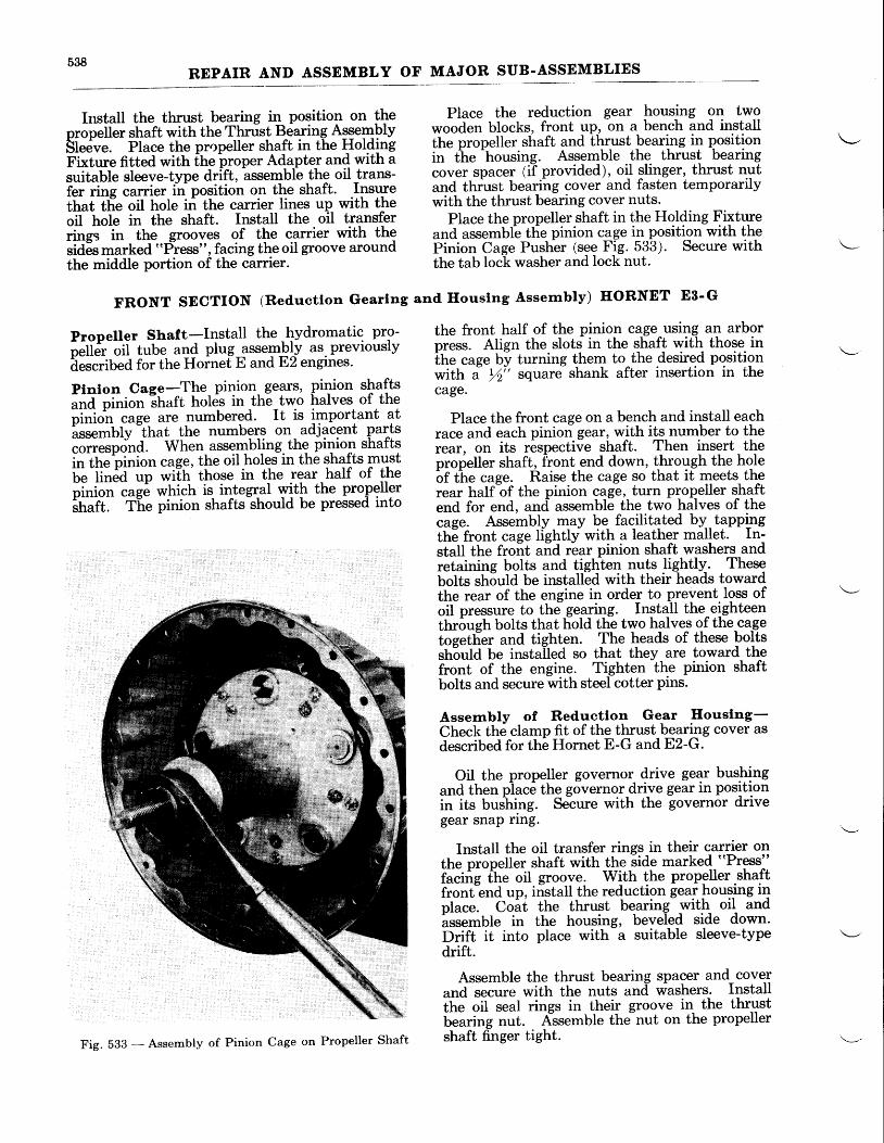
538REPAIR AND ASSEMBLY OF MAJOR SUB-ASSEMBLIES
Install the thrust bearing in position on theoroneller shaft with the Thrust Bearing AssemblySt"d'rre. Place the propeller shaft in the HoldingFi*trte fitted with fhe proper Adapter and with asuitable sleeve-type drift,
-assemble the oil trans-
fer ring carrier in position ol the shaft. Insuretttut tfre oil hole iri the carrier lines up with theoil hol" in the shaft. Install the oil transferrinqs in the grooves of the carrier with thesid6s marked "PYre$s", facing the oil groove aroundthe middle portion of the carrier.
FRONT SECTION (Reductlon Gearlng
Propeller Shaft-Install the hydromatic pro-
;;f"-r-;ii tube ald plug-assembly as. previouslyi"t.tiU"a for the Hoinef E and E2 engines'
Plnlon Cage-The pinion- gears, pilion shafts""a-pi"iott
-tnuft holds in the two halves of the
pi"i"" cage are numbered. It is important atlssemblv ihat the numbers on. adjacent parts."rr.rp""a when assembling. thg pinion shaftsin ttte pinion cag9, the oil.holqs in the shafts musti;;-ii;6d up wilh'those in the rear half of the"i"io" .ug; which is integral with the propgller|h;?l: tfi" pinion shafts should be pressed into
Place the reduction gear housing on twowooden blocks, front up, on a bench and installthe propeller shaft and thrust bearing in positionin the
-housing. Assemble the thrust bearing
cover spacer (i-f provided), oil slinger, thrust nutand thiust bearihg cover and fasten temporarilywith the thrust bearing cover nuts.
Place the propeller shaft in the Holding Fixtureand assembl-e tlie pinion cage in positi-on with thePinion Cage Push-er (see Fig. 533). Secure withthe tab lock washer and lock nut.
and Ilouslng Assernbly) HORNET E3'G
the front half of the pinion cage using an arborpress. Alien the slots in the shaft with those inthe cuge by turning them to the desired positionwith i ,4'' square shank after insertion in thecage.
Place the front cage on a bench and install eachrace and each pinion geat, with its number to therear, on its respective shaft. Then insert thepropeller shaft, front-end down, t-hroggh the holebf ttte cage. Raise the cage so that it meets therear halfbf the pinion cage, turn pro!'eller shaftend for end, and- assemble the two halves of thecage. Assembly nlay be facilitqted by.tapplngth6 front cage lightly with a leather mallet. In-stall the froit and rbar pinion shaft washers andretaining bolts and tighlen nuts lightly. Thesebolts sn5ula be installed with their heads towardthe rear of the engine in order to prevent.loss ofoil pressure to the gearing. Install the^eighteenthrough bolts that hold the two halves of the-ca-getoget6er and tighten. The heads of these boltssh6utd be installed so that they are toward thefront of the engine. Tighten the pinion shaftbolts and secure with steel cotter pins.
Assernbly of Reductlon Gear Eouslng-Check the clamp fit of the thrust bearing cover asdescribed for the Hornet E-G and E2-G.
Oil the propeller governor drive ge?r bushingand then plac,i the governor-dri-ve gear in positionin its buihing. Seiure with the governor drivegear snap ring.
Install the oil transfer rings in their carrier onthe propeller shaft with the side marked "Press"
i""i"g fhe oil groove- With the propeller shaftiront"end up, iistall the reduction gea! housing ir]nlace. Coaf the thrust bearing- with oil and^assemble
in the housing, beveled side down'Drift it into place with-a suitable sleeve-typedrift.
Assemble the thrust bearing spacer and coverand secure with the nuts and washers. Installlhe oil seal rings in their groove iq the thrustbearing nut. Alssemble the nut on the propellershaft finger tight.
F ig .533 -Assemb lyo fP in ionCageonPrope l l e rSha f t
539REPAIR AND ASSEMBLY OF MAJOR SUB.ASSEMBLIES
Carn Reductlon Gear-Coat the inside diam-eter of the cam reduction gear bushing with oiland then place the gear in its bushing. Thegovernor drive gear, (geared Hornets only)should then be placed in position on the front endof the cam reduction gear shaft and secured withthe nut and washer.Propeller Governor Idler Gear (Ilornet E-G,Ez-G, and E3-G)-Drift idler gear bushingthrough front of anchor plate so that locking
grooves are in alignment with each other. In-stall idler gear lock plate and bolt, and stakehead of bolt. Place idler gear on its bushingat the same time meshing it with the idler drivegear.
Governor Otl Feed Plpe (Hornet E-G, Ez-G,and E8-G)-Install the governor oil feed pipein place on the bearing support plate and securethe pipe with its retaining bracket and clip.
Carn Reductlon Gear-Prior to assembly ofthe cam reduction gear on the engine, the camreduction gear locking nut should be tried inposition on the gear to make sure that it seatsoroperlv in the end of the shaft. Then oil theiatti reduction gear bushing and place the camreduction gear in position in its bushing. Placethe Cam Reduction Gear Holder over the front
Front Maln Bearlng Outer Race and Rol-lers-Coat the front main bearing outer race androllers with oil and insert into the front mainbearing liner. On geared engines the front mainbearing outer race and rollers should be securedin position with a retaining nut. This nut con-tains left hand threads and should be turned tothe left with Front Main Bearing Retaining NutWrench. Adjustment for the proper clearancebetween this nut and the front main bearingouter race may be made by grinding the rearface of the nut.
Tappets and Rollers-Prior to assembly of thetappets and rollers in the front half of the maincrinkcase section, the tappets and guides shouldbe given a liberal coating of oil. Then insert eachtappet in its guide and depress until the roller pinholes clear the end of the tappet guide. Insertthe roller in the tappet slot and slide the rollerpin into position, making sure that the ends of theroller pin are inside the tappet guide when thetappet is allowed to return to its normal position.
BEARING SUPPORT PLATE
MAIN CRANKCASE SECTION-WASP JR.
CYLINDERS
of the gear and then assemble the cam reductiongear locking nut in place on the rear end of theshaft and tighten with the Cam Reduction GearNut Wrench. Check the clearance between thelock nut and the bushing and if insufficient, facethe bushing enough to give the required clearancewith the Cam Reduction Gear Bushing Facer.
The valve tappets usgd on early Wasp and H_ornetengines incorporated only two oil drain holes.When installing this type of valve tappet, careshould be taken to align these holes with thegrooves in the tappet guide. The valve tappetsused on later Wasp and Hornet engines have fouroil drain holes, thereby eliminating the possi-bility of installing the tappet so that oil will notdrain through.
Draining type tappets should be installed inthe following tappet guide locations: 1 In., 1 Ex.,2In.,28x.,3 Ex., 8 In., 9 In. and 9 Ex.
Carn and Otl Feed Bracket-Assemble thecam bearing on the cam shelf, making sure it isthoroughly seated by tapping lightly with afiber drift. Coat the inside of cam with oil andassemble the cam over the cam bearing. Assem-ble the cam oil transfer bracket and the camretainer plates and secure with the necessary nuts.The cam end clearance should be checked byinserting a feeler gage between the cam retainerplate and the cam.
MAIN CRANKCASE SECTION-WASP Hl AND HORNET E SERIES
Rocker Arm Bearlngs-Install the rocker armbearings in the rocker arms with the Rocker ArmBearing Assembly Drift and Base (see Fig. 534).The bearings of the early SKF type, having asingle piece inner race for both sets of balls,should be installed in such a manner that the sidethrust is not taken by that portion of the innerand outer race which contains the loadingnotches. The position of the loading notch islocated by a stamped "O" on the inner and outerraces. The marking on the outer race also indi-
cates the position of the oil hole and should beplaced toward the adjusting screw end of therocker when the bearing is installed in the rockerarm. The markings on the inner race should beplaced toward the push rod end of the rockerwhen the rocker arm is installed in the cylinder.
For rocker arm bearings having independentinner races for the two sets of ball bearings, theforegoing instructions are not necessary. Thebearings are installed originally \{rith the grooved
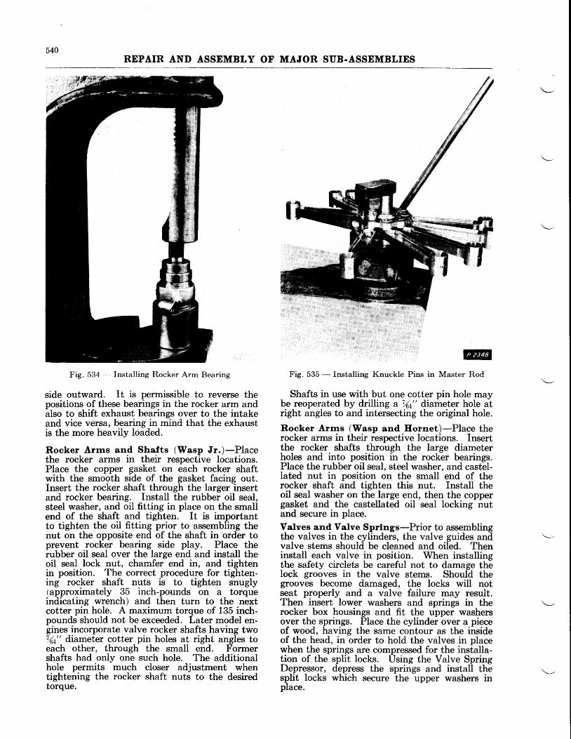
540REPAIR AND ASSEMBLY OF MAJOR SUB.ASSEMBLIES
Fig. 534 Installing Rocker Arm Bearing
side outward. lt is permissible to reverse thepositions of these bearings in the rocker arm andalso to shift exhaust bearings over to the intakeand vice versa, bearing in mind that the exhaustis the more heavily loaded.
Rocker Arrns and Shafts (Wasp Jr.)-Placethe rocker arms in their respective locations.Place the copper gasket on each rocker shaftwith the smooth side of the gasket facing out.Insert the rocker shaft through the larger insertand rocker bearing. Install the rubber oil seal,steel washer, and oil fitting in place on the smallend of the shaft and tighten. It is importantto tighten the oil fitting prior to assembling thenut on the opposite end of the shaft in order toprevent rocker bearing side play. Place therubber oil seal over the large end and install theoil seal lock nut, charnfer end in, and tightenin position. The coruect procedure for tighten-ing rocker shaft nuts is to tighten snugly(approximately 35 inch-pounds on a torqueindicating wrench) and then turn to the nextcotter pin hole. A maximum torque of 135 inch-pounds should not be exceeded. Later model en-gines incorporate valve rocker shafts having two7(4" drameter cotter pin holes at right angles toeach other, through the small end. Formershafts had only one such hole. The additionalhole permits much closer adjustment whentightening the rocker shaft nuts to the desiredtorque.
, @F ig. 535 - Installing Knuckle Pins in Master Rod
Shafts in use with but one cotter pin hole maybe reoperated by drilling d %t" diameter hole atright angles to and intersecting the original hole.
Roeker Arrns (Wasp and Hornet)-Place therocker arms in their respective locations. Insertthe rocker shafts through the large diameterholes and into position in the rocker bearings.Place the rubber oil seal, steel washer, and castel-lated nut in position on the small end of therocker shaft and tighten this nut. Install theoil seal washer on the large end, then the coppergasket and the castellated oil seal locking nutand secure in place.
Valves and Valve Sprlngs-Prior to assemblingthe valves in the cylinders, the valve guides andvalve stems should be cleaned and oiled. Theninstall each valve in position. When installingthe safety circlets be careful not to damage thelock grooves in the valve stems. Should thegrooves become damaged, the locks will notseat properly and a valve failure may result.Then insert lower washers and springs in therocker box housings and fit the upper washersover the springs. Place the cylinder over a pieceof wood, having the same contour as the insideof the head, in order to hold the valves in placewhen the springs are compressed for the installa-tion of the split locks. Using the Valve SpringDepressor, depress the springs and install thesplit locks which secure the upper washers inplace.
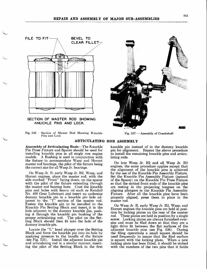
54LREPAIR AND ASSEMBLY OF MAJOR SUB-ASSEMBLIES
FILE TO FIT BEVEL TOCLEAR FILLET
SECTION OF MASTER ROD SHOWINGKNUCKLE PINS AND LOCK.
Fig. 536 -- Section of Master Rod Showing KnucklePins and Lock
ARTICULATING
Assernbly of Artlculatlng Rods-The KnucklePin Press Fixture and Spacer should be used forinstalling knuckle pins in all single row enginemodels. A Bushing is used in conjunction withthe fixture to accommodate Wasp and Hornetmaster rod bearings, the pilot of the fixture beingthe correct size for all Wasp Jr. bearings.
On Wasp Jr. R, early Wasp Jr. F.2, Wasp, andHornet engines, place the master rod, with theside marked "Front" facing down, on the spacerwith the pilot of the fixture extending throughthe master rod bearing bore. Coat the knucklepins and hoies with heavy oil such as KendallNo. 400 Gear Lubricant and insert an undersizedummy knuckle pin in a knuckle pin hole ad-jacent to the rtl" section of the master rod.Fasten the knuckle pin to be installed to theKnuckle Pin Setting Block and inserL it in thehole adjacent to thd dummy knuckle fiin, push-ing it through the knuckle pin bushing of theproper articulating rod. The pilot on the Set-ting Block should then fit into the hole of thedummy knuckle pin.
Locate the "L" head plunger over the SettingBlock and force the knuckle pin into its hole byapplying pressure to the handle of the fixture(see Fig. 535). Install the adjacent knuckle pinand articulating rod in a similar manner, insert-ing the pilot of the Setting Block in the first
@
Fig. 537 - Assembly of Crankshaft
ROD ASSEMBLY
knuckle pin instead of in the dummy knucklepin for alignment. Repeat the above procedureto install the remaining knuckle pins and articu-lating rods.
On late Wasp Jr. 82 and all Wasp Jr. 83engines, the same procedure applies except thatthe alignment of the knuckle pins is achievedby the use of the Knuckle Pin Assembly Fixture.Set the Knuckle Pin Assembly Fixture (insteadof the Spacer) on the Knuckle Pin Press Fixtureso that the slotted front ends of the knuckle pinsare resting in the projecting tongues on thealigning plungers in the Knuckle Pin AssemblyFixture. After all the knuckle pins have beenproperly aligned, press them in place in themaster rod.
On Wasp Jr. B, early Wasp Jr.B,2, Wasp, andHornet engines the knuckle pins are held in posi-tion by locking plates on the rear of the masterrod. These plates are held in position by a singlescrew. Locking plates are always furnished over-size and must be filed down so that they are alight drive fit between the flat surfaces of theadjacent knuckle pins (see Fig. 536). Duringthe filing operations a small square should beused frequently to insure that the filed surfaceis square with the locking plate. When a newlocking plate has been fitted, it should be etchedwith the numbers of the two pins that it holds
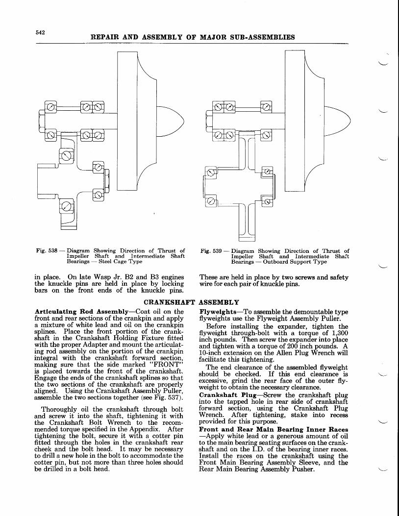
542REPAIR AND ASSEMBLY OF MAJOR SUB.ASSEMBLIES
Fig. 538 - Diagram Showing Direction of Thrust ofImpeller Shaft and Intermediate ShaftBearings - Steel Cage Type
in place. On late Wasp Jr. 82 and B3 enginesthe knuckle pins are held in place by lockingbars on the front ends of the knuckle pins.
CRANKSEAFTArtleulattng Rod Assembly-Coat oil on thefront and rear sections of the crankpin and applya mixture of white lead and oil on the crankpinsplines. Place the front portion of the crank-shaft in the Crankshaft Holding Fixture fittedwith the proper Adapter and mount the articulat-ing rod assembly on the portion of the crankpinintegral with the crankshaft fopward section,making sure that the side marked "FRONT"
is placed towards the front of the crankshaft.Engage the ends of the crankshaft splines so thatthe two sections of the crankshaft are properlyaligned. Using the Crankshaft Assembly Puller,assemble the two sections together (see Fig. 537).
Thoroughly oil the crankshaft through boltand screw it into the shaft, tightening it withthe Crankshaft Bolt Wrench to the recom-mended torque specified in the Appendix. Aftertightening the bolt, secure it with a cotter pinfitted through the holes in the crankshaft rearcheek and the bolt head. It may be necessaryto drill a new hole in the bolt to accommodate thecotter pin, but not more than three holes shouldbe drilled in a bolt head.
Fig. 539 - Diagram Showing Direction of Thrust ofImpeller Shaft and Intermediate ShaftBearings - Outboard Support Type
These are held in place by two screws and safetywire for each pair of knuckle pins.
ASSEMBLYFlywelghts-To assemble the demountable typeflyweights use the Flyweight Assembly Puller.
Before installing the expander, tighten theflyweight through-bolt with a torque of 1,300inch pounds. Then screw the expander into placeand tighten with a torque of 200 inch pounds. A10-inch extension on the Allen PIug Wrench willfacilitate this tightening.
The end clearance of the assembled flyweightshould be checked. If this end clearance isexcessive, grind the rear face of the outer fly-weight to obtain the necessary clearance.Crankshaft Plug-,Screw the crankshaft pluginto the tapped hole in rear side of crankshaftforward section, using the Crankshaft PlugWrench. After tightening, stake into recessprovided for this purpose.Front and. Rear Maln Bearlng Inner Races-Apply white lead or a generoun amount of oilto the main bearing seating surfaces on the crank-shaft and on the I.D. of the bearing inner races.Install the races on the crankshaft using theFront Main Bearing Assembly Sleeve, and theRear Main Bearing Assembly Pusher.
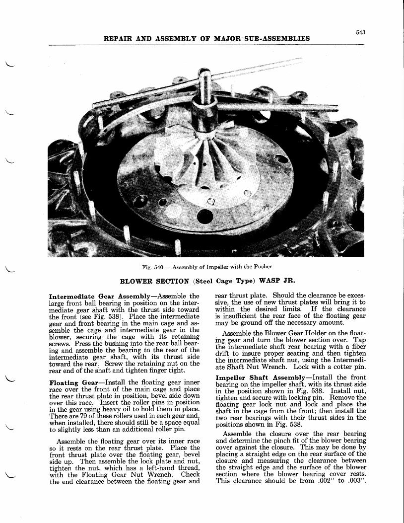
543REPAIR AND ASSEMBLY OF MAJOR SUB.ASSEMBLIES
Fig. 540 - Assembly of Impeller with the Pusher
BLOWER SECTION (Steel
Intermediate Gear Assernbly-Assemble theIarge front ball bearing in position on the inter-me-diate gear shaft with the thrust side towardthe front-(see FiS. 538). Place the intermediategear and front bearing in the main cage and as-semble the cage and intermediate gear in theblower, securing the cage with its retainingscrews. Press the bushing into the rear ball bear-ing and assemble the bearing,to the rear of thein[ermediate gear shaft, with its thrust sidetoward the rear. Screw the retaining nut on therear end of the shaft and tighten finger tight.
Floatlng Gear-Install the floating gear innerrace ovei the front of the main cage and placethe rear thrust plate in position, bevel side downover this race. Insert the roller pins in positionin the gear using heavy oil to hold them in place.There are79 of these rollers used in each gear and,when installed, there should still be a space equalto slightly less than an additional roller pin.
Assemble the floating gear over its inner raceso it rests on the rear thrust plate. Place thefront thrust plate over the floating gear, bevelside up. Then assemble the lock plate,an_d nu!,tighten the nut, which has a left-hand thread,with the Floating Gear Nut Wrench. Checkthe end clearance between the floating gear and
Cage Type) WASP JR.
rear thrust plate. Should the clearance be exces-sive, the use of new thrust plates will bring it towithin the desired limits. If the clearanceis insufficient the rear face of the floating gearmay be ground off the necessary amount.
Assemble the Blower Gear Holder on the float-ing gear and turn the blower section over. Tapth6 intermediate shaft rear bearing with a fiberdrift to insure proper seating and then tightenthe intermediate shaft nut, using the Intermedi-ate Shaft Nut Wrench. Lock with a cotter pin.
knpeller Shaft Assernbly-Install the frontbeaiing on the impeller shaft, with its thrust sidein the position shown in Fig. 538. Install nut,tighten and secure with locking pin. Remove thefloating gear lock nut and lock and place theshaft in the cage from the front; then install thetwo rear bearings with their thrust sides in thepositions shown in Fig. 538.
Assemble the closure over the rear bearingand determine the pinch fit of the blower bearingcover against the closure. This may be done byplacing a straight edge on the rear surface of theclosure and measuring the clearance betweenthe straight edge and the surface of the blowersection where the blower bearing cover rests.This clearance should be from .002" to .003".
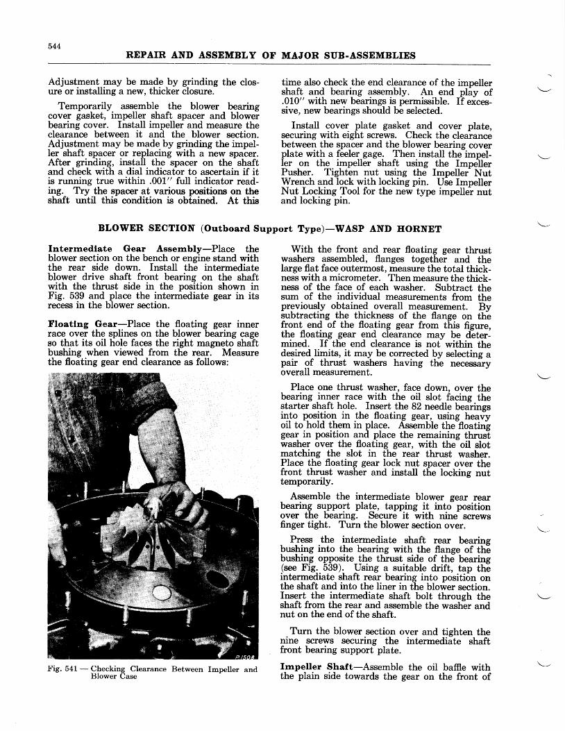
544REPAIR AND ASSEMBLY OF MAJOR SUB-ASSEMBLIES
Adjustment may be made by grinding the clos-ure or installing a new, thicker closure.
Temporarily assemble the blower bearingcover gasket, impeller shaft spacer and blowerbearing cover. Install impeller and measure theclearance between it and the blower section.Adjustment may be made by grinding the impel-ler shaft spacer or replacing with a new spacer.After grinding, install the spacer on the shaftand check with a dial indicator to ascertain if itis running true within .001" full indicator read-ing. Try the spacer at various positions on theshaft until this condition is obfained. At this
Interrnediate Gear Assernbly-Place theblower section on the bench or engine stand withthe rear side down. Install the intermediateblower drive shaft front bearing on the shaftwith the thrust side in the position shown inFig. 539 and place the intermediate gear in itsrecess in the blower section.
Floatlng Gear-Place the floating gear innerrace over the splines on the blower bearing cageso that its oil hole faces the right magneto shaftbushing when viewed from the rear. Measurethe floating gear end clearance as follows:
BLOWER SECTION (Outboard Support Type)-WASP AND HORNET
time also check the end clearance of the impellershaft and bearing assembly. An end pliy of.010" with new bearings is permissible. If exces-sive, new bearings should be selected.
Install cover plate gasket and cover plate,securing with eight screws. Check the clearancebetween the spacer and the blower bearing coverplate with a feeler gage. Then install the impel-ler on the impeller shaft using the ImpellerPusher. Tighten nut using the Impellef NutWrench and lock ryith locking pin. Use ImpellerNut Locking Tool for the new type impeller nutand locking pin.
With the front and rear floating gear thrustwashers assembled, flanges togethei and thelarge flat face outermost, measure the total thick-ness with a micrometer. Then measure the thick-ness of the face of each washer. Subtract thesum of the individual measurements from thepreviously obtained overall measurement. Bysubtracting lhe thickness of the flange on th-efront end of the floa_ting gear from this figure,the floating gear end clearance may be deter-mined. If the end clearance is not within thedesired^Iimits, it may be corrected by selecting apair of thrust washers having the necessaryoverall measurement.
Place one thrust washer, face down, over thebearing _rn4e{ race with the oil slot facing thestarter shaft hole. Insert the 82 needle bearingsinto positiot in the _floating gear, using heavyoil to hold them in place. Assemble the-floatinggea{ in position and place the remaining thrustwasher over the floating gear, with the-oil slotmatching the slot in the rear thrust washer.Place the floating gear lock nut spacer over thefront thrust washer and install the locking nuttemporarily.
Assemble the intermediate blower gear rearbearing sqpport plale, tapping it into positionover the bearing. Secure it with nine screwsfinger tight. Turn the blower section over.
Press the intermediate shaft rear bearingbushing into the bearing with the flange of thebushing opposite the thrust side of the bearing(see Fig..539). Using a suitable drift, tap theintermediate shaft rear bearing into position onthe shaft and into the liner in the blower section.Insert the intermediate shaft bolt throueh theshaft from the rear and assemble the washlr andnut on the end of the shaft.
Turn the blower section over and tighten thenine screws securing the intermediate shaftfront bearing support plate.
Impeller Shaft-Assemble the oil baffie withthe plain side towards the gear on the front of
Fig. 541 - Checking Clearance Between Impeller andBlower Case
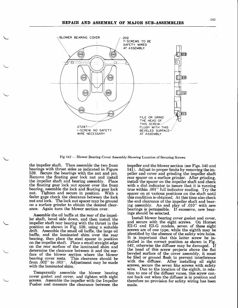
545REPAIR AND ASSEMBLY OF MAJOR SUB.ASSEMBLIES
BLOWER BEARING COVER 2027-SCREWS TO BESAFETY WIREDAT ASSEMBLY.
/',/27297---"I -SCREW. NO SAFETYWIRE NECESSARY.
the impeller shaft. Then assemble the two frontbearings with thrust sides as indicated in Figure539. Secure the bearings with the nut and pin.Remove the floating gear lock nut and inslallthe impeller shaft and bearing assembly. Placethe floating gear lock nut spacer over the frontbearing, aqsemble the lock and floating gear locknut. Tighten and secure in position-.
- With a
feeler gage check the clearance between the locknut and lock. The lock nut spacer may be groundon a surface grinder to obtain the desired- clear-ance. Again turn the blower section over.
Assemble the oil baffie at the rear of the impel-ler shaft, bevel side down, and then install lheimpeller shaft rear bearing with the thrust in theposition as shown in Fig. 539, using a suitabledrift. Assemble the small oil baffie, the large oilbaffie, and the laminated shim over the- rearbearing, thgn place the steel spacer in positionon tbe impeller shaft. Place a small straight edgeon the rear surface of the laminated sliim anddetermine the clearance between it and the sur-face of the blower section where the blowerbearing cover rests. This clearance should befrom .002" to .003". Adjustment may be madewith the laminated shim.
Temporarily assemble the blower bearingcover gasket and cover, and tighten with eighiscrews. Assemble the impeller with the ImpelierPusher and measure the clearance between the
FILE OR GRTND . / .THE HEAD OF , /THls scREgl---" ,FLUSH W|TH TH|S /BEVELED SURFACE-AT ASSEMBLY
h-ig 542 - Blower Bearing Cover Assembly Showing Location of Securing Screws
impeller and the blower section (see Figs. 540 and54L). Adjust to proper limits by removing the im-peller and cover and grinding the impeller shaftrear spacer on a surface grinder. After grinding,install the spacer on the impeller shaft and checkwith a dial indicator to insure that it is runningtrue within .001" full indicator reading. Try thespacer on at various positions on the shaft untilthis condition is obtained. At this time also checkthe end clearance of the impeller shaft and bear-ing assembly. An end play of .010" with newbearings is permissible. If excessive, new bear-ings should be selected.
Install blower bearing cover gasket and cover,and secure with the eight screws. On HornetEz-G and E3-G models, seven of these eightscrews are of one type, while the eighth may beidentified by the absence of the safety wire hbles.It is important that this latter screw be in-stalled in the correct position as shown in Fig.542, otherwise the diffuser may be damaged. Ifthe'head of this screw projedts above ihe flatbeveled surface of the cover assembly, it mustbe filed or ground flush to prevent interferencewith the diffuser. After installing all eightscrews, secure the seven like screws with safetywire. Due to the location of the eighth, in rela-tion to one of the diffuser vanes, this screw can-not back out when the diffuser is in position andther,efore no provision for safety wiring has beenmade.
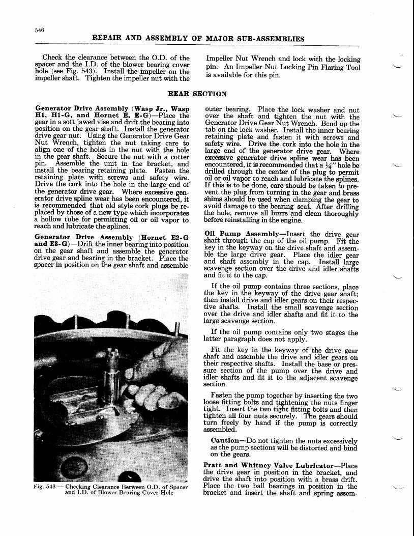
546REPAIR AND ASSEMBLY OF MAJOR SUB-ASSEMBLIES
Check the clearance between the O.D. of the_sp?cer and the I.D. of the blower bearing coverhole (see Fig. 5a3). Install the impellerbn theimpeller shaft. Tighten the impeller nut with the
REAR
Generator l)rlve Assernbly (Wasp Jr., WaspHl, III-G, and Ifornet E. E-G)-Place tliegeaT in a softjawed vise and drift the bearing intoposition on the gegr shaft. Install the genelatordrive gear nut. Using the Generator Diive GearNrt Wrench, tighten the nut taking care toalign one of the holes in the nut witli the holein the gear shaft. Secure the nut with a cotterpin. Assemble the unit in the bracket, andinstall the bearing retaining plate. Fasten theretaining plate with screws and safety wire.Drive the cork into the hole in the large.end ofthe generator drive geal. Where excessive gen-erator drive spline wear has been encountered, itis recommended that old style cork plugs be re-placed by those of a new type which ihcolporatesa hollow tube for permitting oil or oil vipor toreach and lubricate the splines.
Generator Drlve Assernbly (Ifornet E2- Gand E8-G)-Drift the inner bearing into positionon- the gear sbaft and assemble the geheratordrive gear and bearing in the bracket. Place thespacer in position on the gear shaft and assemble
!'ig. 543 - Checking Clearance Between O.D. of Spacerand I.D. of Blower Bearing Cover Hols
Impeller Nut Wrench and lock with the lockingpin. An Impeller Nut Locking Pin Flaring Toolis available for this pin.
SECTION
outer bearing. Place the lock washer and nutover the shaft and tighten the nut with theGenerator Drive Gear Nut Wrench. Bend up thetab on the lock washer. Install the inner bearingretaining plate and fasten it with screws andsafety wire. Drive the cork into the hole in thelarge end of the ge4elator drive gear. Whereexcessive generator drive spline wear has beenencountered, it is recommended that a rZ,, hole bedrilled through the ce-nter of the plug to permitglt gq oil vapor to reach and lubricate the rptitto.If this is to be .done, care should be taken fo pre-v-ept thp plW,from turning in the gear and biassshims should be used when clamping the gear tolvoi-d damage to the bearing sgat. After iiri[ingthe hole,. remove all burrs and clean thorougHtbefore reinstalling in the engine.
Oll^ Purnp _AsFerrrbly-I_nsert the drive gearqhaft through the cap of the oil pump. Fiithekey in the keyway on the drive shaft lnd assem-ble- the lF g" drlrr_" g.ear._ Place the idler gearand shaft assembly in- the .cap. Install largescavenge section over the drive and idler shaftsand fit it to the cap.
If the oil pu4p contain-s lhree sections, placetfe kgV itl_ tltg keyw_ay_ of the drive gear shaft;then install drive and idler ge,4rs on tlieir respec-tive shafts. Install the small scavenge sec-tionover the drive and idler shafts and fif it to thelarge scavenge section.
If the oil pump contains only two stages thelatter paragraph does not apply.
Fit the key i! _the_ keyway of the drive gearshaft and assemble the drive and idler sears ontheir respective shafts. Install the basetr pres-sure section of the pump over the drive- andidler shafts and fit it to the adjacent scavengesection.
Fasten the pgmp together by inserting the twolgo,se fitting bolts and-tightening the nuts fingertigbt. Iqqert the two tight fitting bolts and tlientighter_r a! four nuts securely. TLe gears shouldturn {r-eeJv by hand if the pump
-is correctly
assembled.
Cautlon-Do not tighten the nuts excessivelyas the pump sections will be distorted and binilon the gearc.
Pratt and Whltney Valve Lubrlcator-Placet!,e drive gear in position in the bracket, anddrive the shaft into position with a brass'drift.Place the two ball bearings in position in thebracket and insert the shift and spring assem-
547
REPAIR AND ASSEMBLY OF MAJOR SUB-ASSEMBLIES
bly. Fasten the cover plate, with its,gasket, inposition with the propef nuts and washers.
When installing the valve lubricator, it hasbeen found that lhe marks on the sliding plateshould be set at a point somewhere between one,and one and three-quarters (L%) on the scale.However, this may not be a perrnanent settiqg'although'it may be used dui{ng- run-in of theengine] As a precaution, it is well to remove therodker box covers after about ten (10) minutesof running and check to see if sufficient oil isbeine furnfshed to the rocker mechanism of eachcylinlder. If an ever-supply is being fqnishe-d,wnicn is hkely to cause sfiSht smoking from theexhaust, it tituy be overcome by setting thepointer at a lower position on the scale. If thereis not enough oil found in the rocker boxes, thatis, if the springs, washers, and rockers are notmoist with oil, adjustment should be madetoward the higher end of the scale.
Stde Vacuum Pump Drlve-Drift the innerbearing into position on the vacuum pump drive-
sear shaft. Place the spacer over the gearJnaft and assemble outer bearing over the spacer.Install and tighten the nut which secures thebearing on the shaft. Insure that the hole inthe nuT ahgns with the lock pin hole in the shaft.If a new sf,aft is installed, a hole must be drilledin the shaft with a No. 40 (.098") drill, using the
hole in the nut as a guide. Pin the nut to theshaft with a No. 8 cotter pin.
Starter Shaft and Bearlng-Place the startershaft on a clean wooden bench (gear end down).Assemble the bearing spacer, bevel side down,over the shoulder on the shaft. Push the bearinginto position on the shaft.
Otl Screen and Check Valve Assembly-Insert the oil scr@n and check valve assemblyin the chamber of the rear section; then screwthe oil screen chamber plug in place.
Cautlon-Make sure that the rubber oilseal is correctly positioned between the valveassembly and the screen body.

548REPAIR AND ASSEMBLY OF MAJOR SUB.ASSEMBLIES
TOOL LIST
Tool Narne Tool No.
ADAPTER - Crankshaft Holding Fixture. . .PWA-1919-1
ADAPTDR - Propeller Shaft Holding Fix-ture . . .PWA-1919-1
ADAPTER - Crankshaft Holding Fixture. . .PWA-19L9-2
ADAPTDR - Crankshaft Holding Fixture. . .PWA-1919-3
ADAPTER - Crankshaft and Propeller ShaftHolding Fixture ..PWA-1919-4
ADAPTER - Face Plate, Crankcase Hold-ins . . . .12950-T-11
ADAPTDR - Magneto Shaft Bushing,Reaming . . . .PWA-820
ARBOR - Inlet Valve Seat, Removing PWA-608-1
ARBOR - Master Rod Bearing, Assembty..TAM-315
ARBOR - Master Rod Bearing, Assembly. .TAM-267
ARBOR - Master Rod Bearing, Assembly. .TAM-270
BAR - Aligning, Cam Reduction Gearand Intermediate Governor DriveGear Bushing, Reaming... PWA-959
BAn - A[gning, Magneto Shaft Hole. . . . PWA-1981
BAR - Reamer, Cam Reduction GearBushing PWA-970
BUSEING - Knuckle Pin Bushing Facing(Use with PWA-860 and PWA-861) . . PWA-862-3
BUSEING - Knuckle Pin Bushing Facing(Use with PWA-860 and PWA-861) . . PWA-862-6
BUSEING - Knuckle Pin Bushing Facing(Use with PWA-860 and PWA-861) . .PWA-862-1
BUSHING - Knuckle Pin Press Fixture. . . . PWA-810-1
BUSEING - Knuckle Pin Press Fixture. . . . PWA-810-3
BUSEING - Starter Shaft, Reaming (Usewith PWA-60) . PWA-819
CLAMP - Tappet Guide, Reaming . PWA-1369
CLAMP - Tappet Guide, Reaming . PWA-1370
CLAMP - Tappet Guide, Reaming . PWA-1371
CUTTER - Knuckle Pin Bushing, Facing. . . PWA-861
DEPRDSSOR -Valve Spr ing . . .PWA-459
DRIFT AND BASE - Rocker Bearing, As-sembly and Disas-semblv PWA-614
Wasp Jr. Wasp Eornet
B 82 B3 EI ET- G E E . G E2- G E 3 - G
x x
x
x x x
x
x x x
x x x x x x x x x
x x x x x x x x x
x x x x x x x x x
x x x
x x
x x x x
x x x
x x x x x x x x x
x x x x x
x x x
x x
x x x x
x x
x x x x
x x x x x x x x x
x x x
x x
x x x x
x x x x x x x x x
x x x x x x x x x
x x x x x x x x x
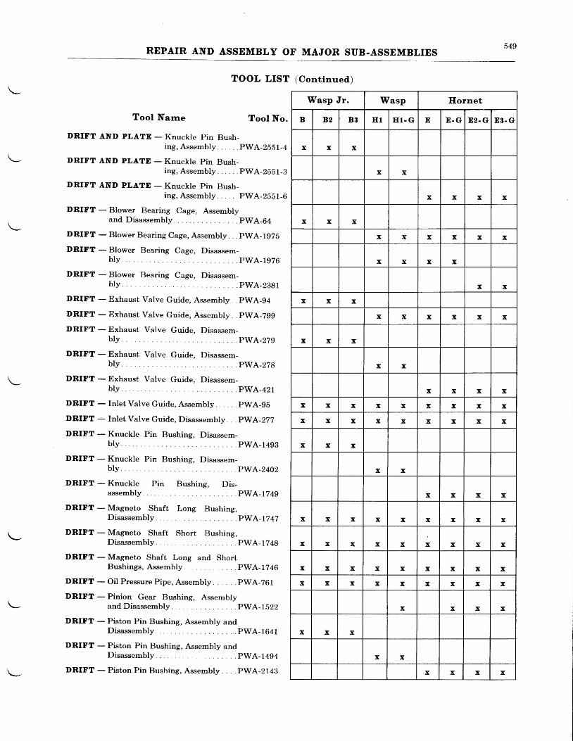
549REPAIR AND ASSEMBLY OF MAJOR SUB.ASSEMBLIES
TOOL LIST (Contlnued)
Tool Narne Tool No.
DRIFT AND PLATE - Knuckle Pin Bush-ing, Assembly . PWA-2SSL-4
DRIFT AND PLATD - Knuckle pin Bush-ing, Assembly. PWA-2551-3
DRIFT AND PLATD - Knuckle Pin Bush-ing, Assembly . . . . .PWA-2SSL-6
DRIFT - Blower Bearing Cage, Assemblyand Disassembly pWA-64
DRIFT - Blower Bearing Cage, Assembly. . . pWA-lgZb
DRIFT - Blower Bearing Cage, Disassem-bly . .PwA-r976
DRIFT - Blower Bearing Cage, Disassem-bly PwA-2881
DRIFT - Exhaust Valve Guide, Assembly. . pWA-94
DRIFT - Exhaust Valve Guide, Assembly . pWA-Zgg
DRIFT - Exhaust Valve Guide, Disassem-PWA-279
DRIFT - Exhaust Valve Guide. Disassem-blv.
DRIFT - Exhaust Valve Guide, Disassem-bly PwA-421
DRIFT - Inlet Valve Guide, Assembly PWA-95
DRIFT - Inlet Valve Guide, Disassembly . . .PWA-277
DRIFT - Knuckle Pin Bushing, Disassem-bly . PWA-1493
DRIFT - Knuckle Pin Bushing, Disassem-bly. . .PwA-2402
DRIFT - Knuckle Pin Bushing, Dis-a s s e m b l y . . . . . . P W A - 1 7 4 9
DRIFT - Magneto Shaft Long Bushing,Disassembly . . . . PWA-1?42
DRIFT - Magneto Shaft Short Bushing,Disassembly . . . . PWA-1?48
DRIFT - Magneto Shaft Long and ShortBushings, Assembly ..PWA-1?46
DRIFT - Oil Pressure Pipe, Assembly PWA-261
DRIFT - Pinion Gear Bushing, Assemblyand Disassembly PWA-1522
DRIFT - Piston Pin Bushing, Assembly andD isassemb ly . . . . PWA-1641
DRIFT - Piston Pin Bushing, Assembly andDisassembly . . . . PWA-1494
DRIFT - Piston Pin Bushing, Assembly . . PWA-2149
Wasp Jr. Wasp Ilornet
B 82 B3 E I E I . G E E . G D2. G 88 . G
x x x
x x
x x x x
x x x
x x x x x x
x x x x
x x
x x x
x x x x x x
x x x
x x
x x x x
x x x x x x x x x
x x x x x x x x x
x x x
x x
x x x x
x x x x x x x x x
x x x x x x x x x
x x x x x x x x x
x x x x x x x x x
x x x x
x x x
x x
x x x x
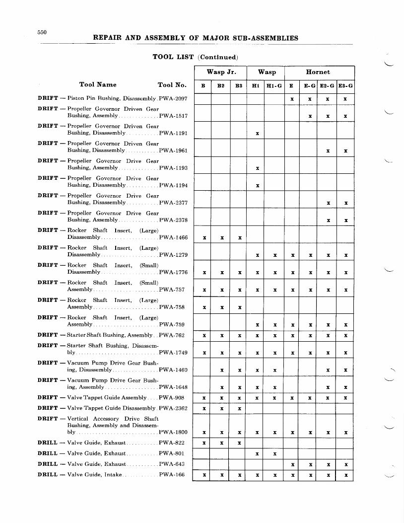
550REPAIR AND ASSEMBLY OF MAJOR SUB.ASSEMBLIES
TOOL LIST (Contlnued)
Tool Narne Tool No.
DRIFT - Piston Pin Bushing, Disassembly PWA-2092
DRIFT - Propeller Governor Driven GearBushing,Assembly . .PWA-1512
DRIFT - Propeller Governor Driven GearBush ing , D i sassemb ly . . . . .PWA-1191
DRIFT - Propeller Governor Driven GearBushing, Disassembly.. . . . .PWA-1961
DRIFT - Propeller Governor Drive GearBushing, Assembly . .PWA-1193
DRIFT - Propeller Governor Drive GearBushing, Disassembly. . . . . .PWA-1194
DRIFT - Propeller Governor Drive GearBushing, Disassembly... .PWA-2377
DRIFT - Propeller Governor Drive GearBushing, Assembly .. .PWA-2378
DRIFT - Rocker Shaft Insert, (Large)Disassembly . . . . PWA-1466
DRIFT - Rocker Shaft Insert, (Large)D i sassemb ly . . . . PWA-1279
DRIFT - Rocker Shaft fnsert, (Smalt)Disassembly . . . . PWA-1776
DRIFT - Rocker Shaft fnsert, (Small)Assembly PWA-757
DRIFT - Rocker Shaft Insert, (Large)Assembly PWA-758
DRIFT - Rocker Shaft Insert, (Large)Assembly PWA-759
DRIFT - Starter Shaft Bushing, Assembly. . PWA-762
DRIFT - Starter Shaft Bushing, Disassem-bly . PWA -r7 49
DRIFT - Vacuum Pump Drive Gear Bush-ing, Disassembly PWA-1460
DRIFT - Vacuum Pump Drive Gear Bush-ing, Assembly PWA-1648
DRIFT - Valve Tappet Guide Assembly. . . PWA-908
DRIFT - Valve Tappet Guide Disassembly. PWA-2362
DRIFT - Vertical Accessory Drive ShaftBushing, Assembly and Disassem-b l y . . . . P W A - 1 8 0 0
DRILL - Valve Guide, Exhaust PWA-822
DRILL - Valve Guide, Exhaust PWA-801
DRILL - Valve Guide, Exhaust PWA-643
DRILL - Valve Guide, Intake PWA-166
Wasp Jr. Wasp Ilornet
B 82 B3 E 1 E l . G E D . G E2- G E3. G
x x x x
x x x
x
x x
x
x
x x
x x
x x x
x x x x x x
x x x x x x x x x
x x x x x x x x x
x x x
x x x x x x
x x x x x x x x x
x x x x x x x x x
x x x x x x
x x x x x x
x x x x x x x x x
x x x
x x x x x x x x x
x x x
x x
x x x x
x x x x x x x x x
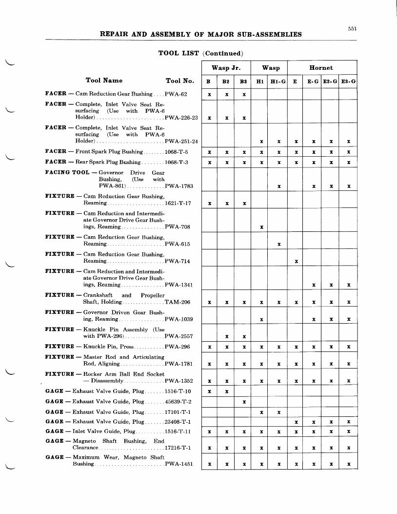
551REPAIR AND ASSEMBLY OF MAJOR SUB.ASSEMBLIES
TOOL LIST (Contlnued)
Tool Narne Tool No.
FACER - Cam Reduction Gear Bushing. . . . PWA-62
FACER - Complete, Inlet Valve Seat Re-\- surfacing (Use with PWA-6
Holder) . . .PWA-226-29
FACDR - Complete, Inlet Valve Seat Re-surfacing (Use with PWA-6Holder) . . .PWA-25L-24
FACER - FrontSpark Plug Bushing. . . . . . . . 1008-T-b\-
tr. ACER - Rear Spark Plug Bushing. . . 106g-T-g
FACINGI TOOL - Governor Drive GearBushing, (Use withPWA-861) . . .PWA-1783
FIXTURE - Cam Reduction Gear Bushing,Reaming . . . . L62L -T -L7
FIXTURE - Cam Reduction and Intermedi-ate Governor Drive Gear Bush-ings, Reaming. . . . .PWA-708
FIXTURE - Cam Reduction Gear Bushing,Reaming . . . .PWA-615
FIXTURE - Cam Reduction Gear Bushing,
\ - Reaming . . . .PWA-214
FIXTURE - Cam Reduction and Intermedi-ate Governor Drive Gear Bush-i ngs , Reaming . . . . .PWA-1341
FIXTURE - Crankshaft and PropellerShaf t , Hold ing . . . .TAM-206
I'IXTURD - Governor Driven Gear Bush-i ng , Reaming . . . . .PWA-1039
FIXTURE - Knuckle Pin Assembly (Usewi thPWA-296\ . . .PWA-2557
FIXTURE - Knuckle Pin, Press PWA-296
FIXTURD - Master Rod and ArticulatingRod , A l i gn ing . . . . .PWA-1781
\- FIXTURE - Rocker Arm Ball End SocketDisassembly . . . . PWA-1352
GAGD - Exhaust Valve Guide, Plug. 1516-T-10
GIAGE - Exhaust Valve Guide, Plug. .45639-T-2
GAGTD - Exhaust Valve Guide, PIug. . 17101-T-1
\- GAGE - Exhaust Valve Guide, Plug. 23408-T-1
GAGD - Inlet Valve Guide, PIug. . . .1516-T-11
GAGD - Magneto Shaft Bushing, EndClearance . .17216-T-I
GAGE - Maximum Wear, Magneto Shaft
l - Bushing . . .PWA-1451
Wasp Jr. Wasp Hornet
B 82 B8 E 1 E l - G E E . G 82. G E8- e
x x x
x x x
x x x x x x
x x x x x x x x x
x x x x x x x x x
x x x x
x x x
x
x
x
x x x
x x x x x x x x x
x x x x
x x
x x x x x x x x x
x x x x x x x x x
x x x x x x x x x
x x
x
x x
x x x x
x x x x x x x x x
x x x x x x x x x
x x x x x x x x x
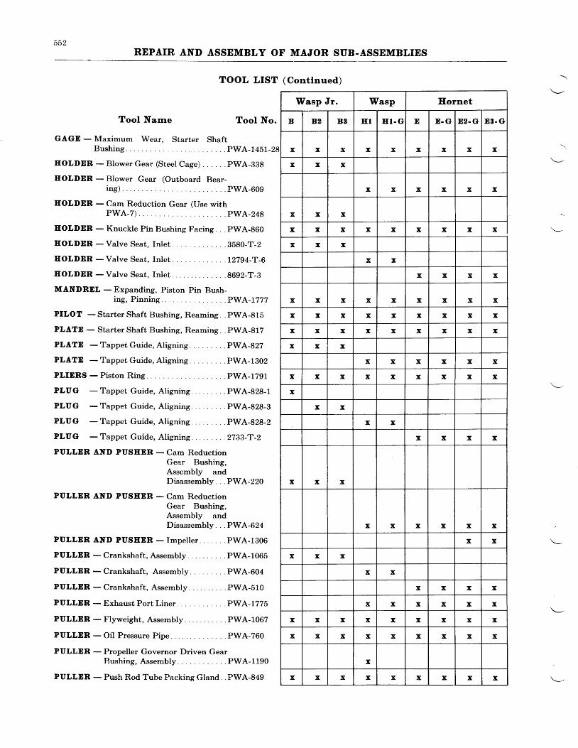
552REPAIR AND ASSEMBLY OF MAJOR SUB.ASSEMBLIES
TOOL LIST (Conttnued)
TooI Narrre Tool No.
GAGE - Maximum Wear. Starter ShaftBushing . PWA-145I-28
EOLDDR - Blower Gear (Steet Cage) . PWA-398
EOLDDR - Blower Gear (Outboard Bear-i r r g ) . . . . pwA_609
EOLDER - Cam Reduction Gear (Use withPWA-7) PWA_248
EOLDDR - Knuckle Pin Bushing Facing. . . PWA-8G0
EOLDDR - Valve Seat, Inlet. . .3b80-T-2
EOLDER - Valve Seat, Inlet. . .L2794-T-B
EOLDER - Valve Seat, Inlet. .8692-T-8
MANDRDL - Expanding, Piston Pin Bush-ing, P inn ing. . . . .PWA-L777
PILOT - Starter Shaft Bushing, Reaming. . PWA-815
PLATE - Starter Shaft Bushing, Reaming. . PWA-812
PLATD -TappetGuide,Al igning . . .PWA-82?
PLATD -TappetGuide,Al igning . . .PWA-1302
PLIERS - Piston Ring. . .PWA-1791
PLUG -Tappet Guide, Al igning .. .PWA-828-1
PLUG -Tappet Guide, Al igning .. .PWA-828-3
PLUG -Tappet Guide,Al ign ing . . .PWA-828-2
PLUG - Tappet Guide, Aligning . . .2733-T-2
PULLER AND PUSEEB - Cam ReductionGear Bushing,Assembly andDisassembly. . . PWA-220
PULLER AND PUSEER - Cam ReductionGear Bushing,Assembly andDisassembly. . . PWA-624
PULLER AND PUSEER - Impel ler . . . . . . .PWA-1306
PULLER -Crankshaft,Assembly . . . .PWA-1065
PULLER -Crankshaft, Assembly . . .PWA-604
PULLDR -Crankshaft, Assembly .. . .PWA-510
PULLDR - Exhaust Port Liner . PWA-1775
PULLER-Flyweight , Assembly . . .PWA-1067
PULLER - Oil Pressure Pipe. . . PWA-760
PULLDR - Propeller Governor Driven GearBushing, Assembly .PWA-1190
PULLER - Push Rod Tube Packing Gland PWA-849
Eornet
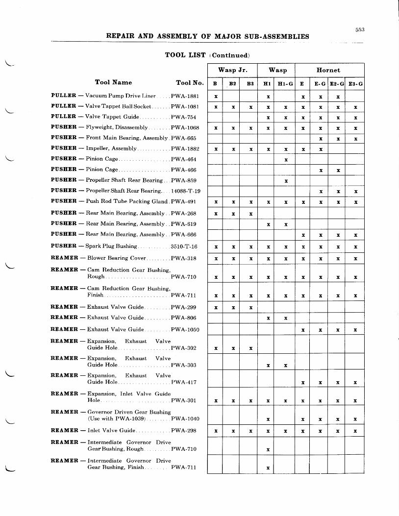
DD.J
REPAIR AND ASSEMBLY OF MAJOR SUB-ASSEMBLIES
TOOL LIST tContlnued)
Tool Narne Tool No.
PULLDR - Vacuum Pump Drive Liner pWA-1881
PULLER - ValveTappet Bal lSocket. . . . . . .pWA-1081
PULLER - Valve Tappet Guide pWA-254
PUSEER -Flyweight,Disassembly . .pWA-1068
PUSEDR - Front Main Bearing, Assembly pWA-66b
PUSEDR - Impel ler , Assembly . . . . . .PWA-1882
PUSEER-Pin ion Cage . .PWA-4G6
PUSEDR - Propeller Shaft Rear Bearing PWA-859
PUSEER - Propeller Shaft ll,ear Bearing.. . . 14088-T-19
PUSEER - Push Rod Tube Packing Gland. PWA-491
PUSEER - Rear Main Bearing, Assembly. . PWA-208
PUSEDR - Rear Main Bearing, Assembly PWA-O19
PUSEER - Rear Main Bearing, Assembly. . PWA-GG6
PUSEER -Spa rkP lugRush ing . . . . . . 3510 -T -16
REAMER - Blower Bearing Cover . . PWA-818
RDAMDR - Cam Reduction Gear Bushing,Rough PWA-210
BDAMER - Cam Reduction Gear Bushing,Finish . . PWA-711
REAMER - Exhaust Valve Guide PWA-299
RDAMDR - Exhaust Valve Guide . PWA-806
RDAMER -Exhaust Valve Guide . . .PWA-1050
REAMER - Expansion, Exhaust ValveGuide Hole. PWA-302
RDAMER - Expansion, Exhaust ValveGuide Hole. PWA-303
REAMDR - Expansion, Exhaust ValveGuide Hole. . PWA-417
REAMER - Expansion, Inlet Valve GuideHole. . PWA-301
REAMER - Governor Driven Gear Bushing(Use with PWA-1039) PWA-1040
REAMER - Inlet Valve Guide . PWA-298
REAMER - Intermediate Governor DriveGearBush ing ,Rough . . . . PWA-710
REAMER - Intermediate Governor f)riveGear Bushing, Finish . PWA-711
Wasp Jr. Wasp Ilornet
B 82 B3 E 1 E l - G E E - G E2. G E 3 . G
x x x x x
x x x x x x x x x
x x x x x x
x x x x x x x x x
x x x
x x x x x x x
x
x x
x
x x x
x x x x x x x x x
x x x
x x
x x x x
x x x x x x x x x
x x x x x x x x x
x x x x x x x x x
x x x x x x x x x
x x x
x x
x x x x
x x x
x x
x x x x
x x x x x x x x x
x x x x x
x x x x x x x x x
x
x
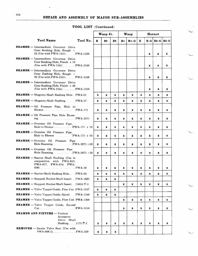
554REPAIR AND ASSEMBLY OF MAJOR SUB.ASSEMBLIES
TOOL LIST (Cont lnued)
Tool Narne Tool No.
REAMDR - Intermediate Governor DriveGear Bushing Hole, Rough +10 (Use with PWA-1341) . PWA-1339
REAMER - Intermediate Governor DriveGear Bushing Hole, Finish * 10(Usewi th PWA-1341) . . .PWA-1940
REAMER - Intermediate Governor DriveGear Bushing Hole, Rough +20 (Use with PWA-1341) PWA-1349
REAMER - Intermediate Governor DriveGear Bushing Hole, Finish * 20(Use with PWA-1341) . PWA-1350
REAMER - Magneto Shaft Bushing Hole. . PWA-61
REAMER - Magneto Shaft Bushing . PWA-57
RDAMER - Oil Pressure Pipe, Hole toBlower PWA-171
REAMER - Oil Pressure Pipe Hole Ream-i n g . . . . . P W A - 2 0 7 1
REAMER - Oversize Oil Pressure Pipe,HoIe to Blower . . PWA-171 + 10
REAMDR - Oversize Oil Pressure Pipe,Hole to Blower PWA-171 + 20
RDAMER - Oversize Oil Pressure PipeHole Reaming. . PWA-2071+10
RDAMER - Oversize Oil Pressure PipeHole Reaming. . . PWA-2071 +20
REAMER - Starter Shaft Bushing (Use inconjunction with PWA-815,PWA-917, PWA-919, PWA-820) PWA-58
REAMER - Starter Shaft Bushing Hole. . . . PWA-60
REAMER - Stepped, Rocker Shaft Insert . PWA-1682
REAMDR - Stepped, Rocker Shaft Insert. . . 13824-T-3
REAMER - Valve Tappet Guide, Firsr Cut. PWA-1347
REAMER - Valve I'appet Guide, Spiral . . . PWA-1348
RDAMER - Valve Tappet Guide, First Cut. PWA-1368
REAMDR - Valve Tappet Guide, SecondCut PWA-1346
REAMER AND FIXTUBD - Vert icalAccessoryDrive ShaftB u s h i n g . . . . . 1 1 7 1 - T - 1
REMOVER - Intake Valve Seat (Use withPWA-608-1) . . PWA-329
Iilasp Jr. Wasp Ilornet
B B2 B3 E 1 H T - G E E . G E2- G 83. G
x x x
x x x
x x x
x x x
x x x x x x x x x
x x x x x x x x x
x x x x x x x x x
x x x x x x x x x
x x x x x x x x x
x x x x x x x x x
x x x x x x x x x
x x x x x x x x x
x x x x x x x x x
x x x x x x x x x
x x x
x x x x x x
x x x
x x x
x x x x x x
x x x x x x
x x x x x x x x x
x x x
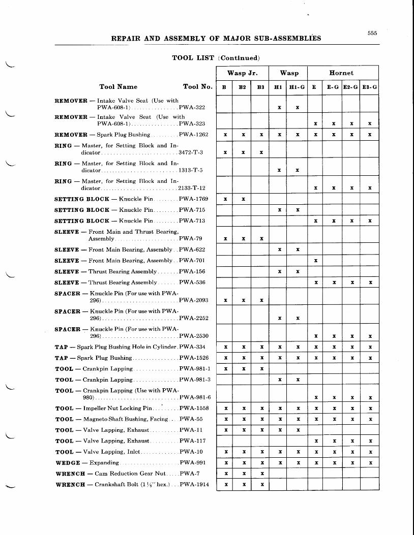
555REPAIR AND ASSEMBLY OF MAJOR SUB-ASSEMBLIES
TOOL LIST (Contlnued)
Tool Narne Tool No.
RDMOVER - Intake Valve Seat (Use withPWA-608-1) PWA-322
REMOVDR - Intake Valve Seat (Use withPWA-608-1) PWA-323
RDMOVER -SparkPlugBushing . . . .PWA-1262
RING - Master, for Setting Block and In-d i c a t o r . . . . 3 4 7 2 - T - 3
RING - Master, for Setting Block and In-d i c a t o r . . . . 1 3 1 3 - T - 5
RING - Master, for Setting Block and In-d i ca to r . . . . 2733 -T -12
SDTTING BLOCK - Knuckle Pin . .PWA-1769
SETT ING BLOCK -Knuck le P in . . .PWA-715
SDTTING BLOCK -Knuck le P in . . .PWA-713
SLDEVE - Front Main and Thrust Bearing,Assembly PWA-79
SLDDVE - Front Main Bearing, Assembly . .PWA-622
SLEEVE - Front Main Bearing, Assembly. . PWA-701
SLEEVD - Thrust Bearing Assembly . . PWA-156
SLEEVD - Thrust Bearing Assembly . . PWA-536
SPACDR - Knuckle Pin (For use with PWA-296). PWA-2093
SPACER - Knuckle Pin (For use with PWA-296) . . . .PWA-2252
SPACER - Knuckle Pin (For use with PWA-296) . . PWA-2530
TAP - Spark Plug Bushing Hole in Cylinder. PWA-334
TAP -Spark P lug Bushing. . . . .PWA-1526
TOOL-Crankp inLapp ing . . . . .PWA-981 -1
T O O L - C r a n k p i n L a p p i n g . . . . . P W A - 9 8 1 - 3
\- TOOL - Crankpin Lapping (Use with PWA-
980). PWA-981-6
TOOL - Impeller Nut Locking Pin. . : . . .PWA-1558
TOOL - Magneto Shaft Bushing, Facing. . . . PWA-55
TOOL -Va l ve Lapp ing , Exhaus t . . . .PWA- l l
TOOL -Va l ve Lapp ing , Exhaus t . . . .PWA-117
TOOL - Valve Lapping, Inlet. PWA-10
WEDGE -Expandi t tg . . . PWA-991
WRENCE - Cam Reduc t i on Gea r Nu t . . . . .PWA-7
WRENCE - Crankshaft BoIt ( Ir4" hex.) . . . PWA-1914
Wasp Jr. Wasp Hornet
B B2 B3 E 1 E l - G E E - G 82. G E 3 . G
x x
x x x x
x x x x x x x x x
x x x
x x
x x x x
x x
x x
x x x x
x x x
x x
x
x x
x x x x
x x x
x x
x x x x
x x x x x x x x x
x x x x x x x x x
x x x
x x
x x x x
x x x x x x x x x
x x x x x x x x x
x x x x x
x x x x
x x x x x x x x x
x x x x x x x x x
x x x
x x x
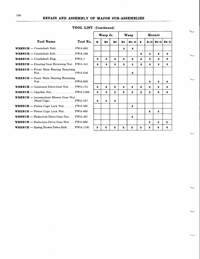
oDo
REPAIR AND ASSEMBLY OF MAJOR SUB.ASSEMBLIES
TOOL LIST (Conttnued)
WRENCH
WRDNCE
WRENCH
WRENCE
WRENCE
WRDNCH
WRENCE
WRENCE
WRENCE
WRDNCE
WRDNCE
WRDNCE
WRENCE
WRENCE
Tool Narne Tool No.
- Crankshaft Bolt . PWA-603
- Crankshaft Bolt PWA-106
- Crankshaft Plug . . PWA-7
- Floating Gear Retaining Nut. . PWA-345
- Front Main Bearing RetainingNut. . PWA-648
- Front Main Bearing RetainingNut PWA-659
- Generator Drive Gear Nut PWA-174
- Impeller Nut PWA-1269
- Intermediate Blower Gear Nut
. (Steel Cage) . PWA-347
- Pinion Cage Lock Nut. . PWA-502
- Pinion Cage Lock Nut. . PWA-660
- Reduction Drive Gear Nut . . PWA-487
- Reduction Drive Gear Nut. . PWA-660
- Spring BlowerDrive Bolt. . . . . .PWA-1195
Wasp Jr. Wasp Hornet
B 82 B3 E T HT- G E E . G D2. G 83. G
x x
x x x x
x x x x x x x x x
x x x x x x x x x
x
x x x
x x x x x x x x x
x x x x x x x x x
x x x
x
x x
x
x x x
x x x x x x x x x
601
After the sub-assemblies and accessories havebeen cleaned, inspected, repaired and reassem-bled as described in the previous chapters, theyshould be forwarded to the final assembly linefor assembly.
The instructions in this chapter are writtenwith the assumption that new gaskets and rubberseals will be installed where they are required,
CHAPTER VI
FINAL ASSEMBLY
GENERAL INFORMATION
FINAL ASSEMBLY
replacing those which were removed at dis-assembly; all mating gears, shafts, bearings andfitting surfaces on oil pipes will be adequatelyoiled prior to installation; all safety wiring,palnuts and cotter pins will be installed wherenecessary, following the final assembly of eachpart; and all the necessary fits and clearanceswill be checked for the required limits containedin the Service Table of Clearances.
Blower and Rear Sectlons-Turn the swiveltop of the Engine Overhaul stand to a horizontalposition and attach the blower section to thetop of the Mountilg Plate with the impellerfacine downward. Then secure blower section tostand- with at least five mounting bolts.
Turn the blower section so that impeller isfacing upward.
Fit gasket over studs and on the parting faceof blower section, where it joins the rear section.Then assemble rear section to blower and securewith the necessary nuts and washers. It mayprove necessary to lightly tap the rear sectionirittr a fiber drift at the magneto and starterdrive shaft locations. Be sure case or bushingsare not distorted or damaged.
Cautlon-The rear section should be pushedevenly on the blower to prevent damagingthe oil pressure pipe and horizontal drive shaftbushings.
Turn the accessory section with the stand sothat the rear section lies in its normal flyingposition and proceed with the installation ofthe following:
Vertlcal Accessory I)rlve Shaft-Insert eachshaft through its respective bushing in the rearsection. Fit ball bearing (and gun control gear,if provided) over upper end of each vertical driveshaft and secure with nut. Each nut should betightened only finger tight on its respectiveshaft at this time.
Tachorneter Shafts-Insert tachometer shaftinto its respective hole in the rear section andensase its gear teeth with those on verticalacdeslory diive shaft. Place gasket againsttachometer coupling mounting pad on rear sec-tion. Then secure tachometer shaft in positionby fastening tachometer drive coupling to rearsection with two fillister head screws. The
tachometer shaft or shafts may be installed onleft and/or right side of the rear section, depend-ing upon whether one or two shafts are used. Inthis connection, it is important to install eachtachometer drive coupling on its particular sideof the engine. Each coupling has a spiral oilgroove in its bore to provide a return for the oilwhich leaks past the bushing. If installed onthe wrong side, this groove would assist oil leak-age rather than prevent it. On engines shippedfrom the factory the tachometer drive pads onthe rear section are marked No. "1" for the rightside, and No. "2" for the left side (viewed fror^rthe rear). The couplings are similarly markedand the numbers on the rear section and couplingshould correspond when properly positioned.
Starter Jaw and Shaft-Insert starter shaftthrough its bushing so that the splined end ofthe shaft protrudes into the rear section. Ifnecessary, tap shaft with hammer and fiberdrift and drive ball bearing completely intorecess of blower section. Fit starter jaw andwasher over end of starter shaft in the ordermentioned; then screw nut on end of shaft andtighten.
Starter Shaft End Clearance-After installa-tion of the starter shaft, the clearance betweenthe starter jaw and the face of the starter shaftbushing should be checked. As all engines arecarefully checked before leaving the factory forthe desired starter shaft end clearance, it shouldnever be necessary to increase this clearanceexcept when new parts are installed, or unless agasket of abnormal thickness is used betweenthe blower and rear section. However, if lessthan the minimum clearance is found with theoriginal parts installed, check to see that thebushing has not worked backwards in the rearsection.
Should the end clearance be excessive, theflange of the starter shaft bushing should be
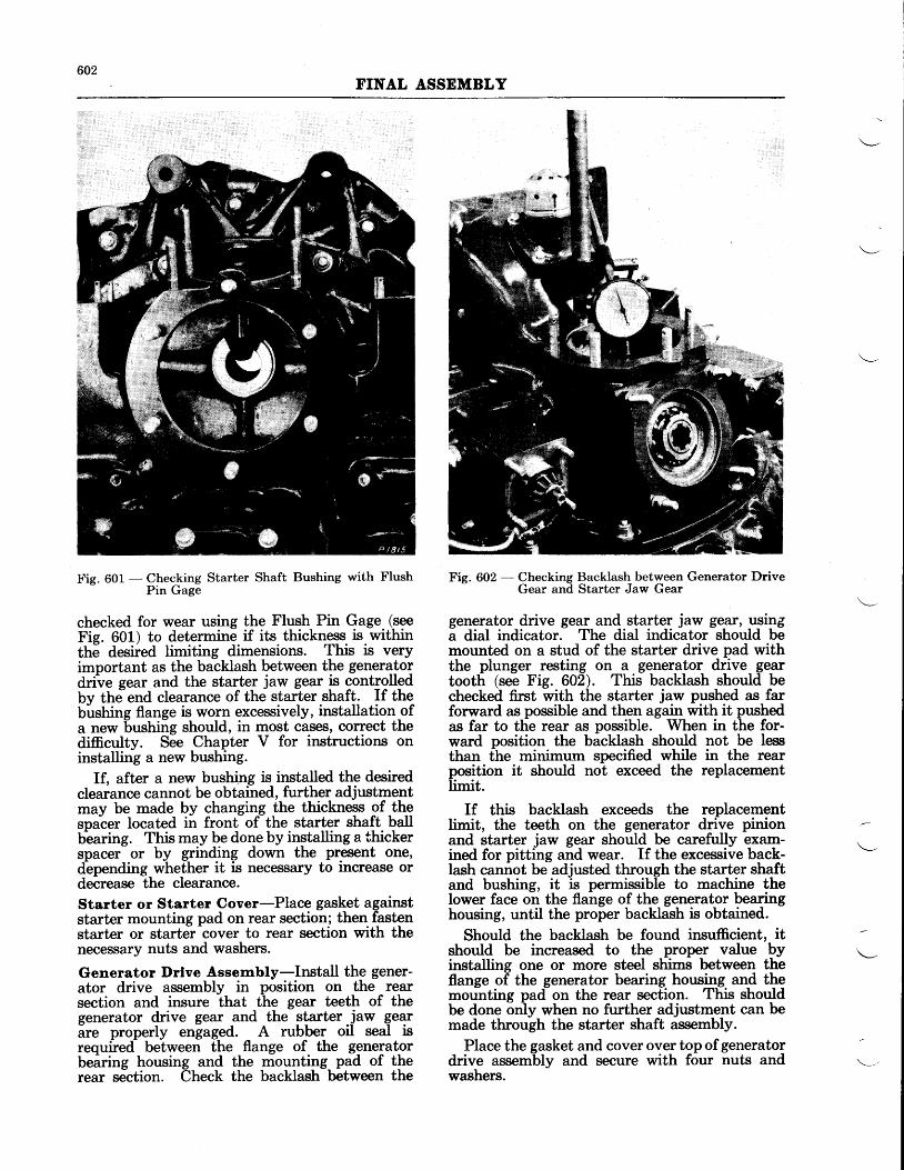
602FINAL ASSEMBLY
Fie. 601 - Checking Starter Shaft Bushing with Flush- Pin Gage
checked for wear using the Flush Pin Gage (seeFie. 601) to determine if its thickness is withinth6 desired limiting dimensions. This is veryimportant as the backlash between the generatordrive gear and the starter jaw gear is controlledbv the end clearance of the starter shaft. If thebirshing flange is worn excessively, installation ofa new bushing should, in most cases, correct thedifficulty. See Chapter V for instructions oninstalling a new bushing.
If, after a new bushing is installed the de.siredclearance cannot be obtained, further adjustmentmay be made by changrng the thickness of therpu-c"r located iir fronfof-the starter shaft ballbbaring. This may be done by installing a thickerspacer or by grinding down the present one,d-epending whether it is necessary to increase ordecrease the clearance.Starter or Starter Cover-Place gasket againststarter mounting pad on rear section; then fastenstarter or starter cover to rear section with thenecessary nuts and washers.
Generator Drlve Assembly-Install the gener-ator drive assembly in position on the rearsection and insure that the gear teeth of thegenerator drive gear and the qtarter -ju* gearare properly engaged. A rubber oil seal isrequired between the flange of the generatorbeiring housing and the mounting pad of therear section. Check the backlash between the
Fig. 602 - Checking Backlash between Generator DriveGear and Starter Jaw Gear
generator drive gear and starter jaw g€r, usi4ga dial indicator. The dial indicator should bemounted on a stud of the starter drive pad withthe plunger resting on a generator drive geartooth (see Fig. 602). This backlash should bechecked first with the starter jaw pushed as farforward as possible and then again with it pushedas far to the rear as possible. When in the for-ward position the backlash should not be lessthan the minimum specified while in the rearposition it should not exceed the replacementlimit.
If this backlash exceeds the replacementlimit, the teeth on the generator drive pinionand starter jaw gear should be carefully exam-ined for pitting and wear. If the excessive back-lash cannot beadjusted through the starter shaftand bushing, it is prmissible to machine thelower face on the flange of the generator bearinghousing, until the proper backlash is obtained.
Should the backlash be found insufficient, itshould be increased to the proper value byinstalling one or more steel shims between theflange of the generator bearing housing and themounting pad on the rear section. This shouldbe done only when no further adjustment can bemade through the starter shaft assembly.
Place the gasket and cover over top ofgeneratordrive assembly and secure with four nuts andwashers.
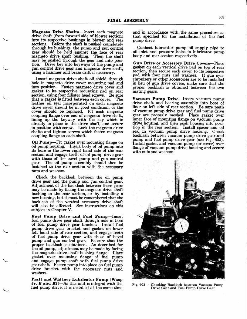
603FINAL ASSEMBLY
Magneto Drlve Shafts-Insert each magnetodrive shaft (from forward side of blower section)into its respective bushings in blower and rearsections. Before the shaft is pushed completelythrough its bushings, the pump and gun controlgear should be held against the face of rearmagneto drive shaft bushing. Then the shaftmay be pushed through the gear and into posi-tion. Drive key into keyways of the pump andgun control drive gear and magneto drive shaft,using a hammer and brass drift if necessary.
Insert magneto drive shaft oil shield throughhole in magneto drive cover mounting pad andinto position. Fasten magneto drive cover andgasket to its respective mounting pad on rearsection, using four fillister head screws. Be surethat a gasket is fitted between each cover. Theleather oil seal incorporated on each magnetodrive cover should be in good condition, or thecover should be replaced. Fit each magnetocoupling flange over end of magneto drive shaft,lining up the keyway with the key which isalready in place in the drive shaft, and securein position with screw. Lock the magneto driveshafts and tighten screws which fasten magnetocoupling flange to each shaft.
OII Pump-Fit gasket over mounting flange onoil pump housing. Insert body of oil pump intoits bore in the lower right hand side of the rearsection and engage teeth of oil pump drive gearwith those of the bevel pump and gun controlgear. The oil pump assembly should then befastened to the rear section with the necessarynuts and washers.
Check the backlash between the oil pumpdrive gear and the pump and gun control gear.Adjustment of the backlash between these gearsrmay be made by facing the magneto drive shaftbushing in the rear section, or by installing anew bushing, but it must be remembered that thebacklash of the vertical accessory drive shaftwill also be affected. See instructions on thissubject in Chapter V.
Fuel Pump l)rlve and Fuel Pump-Insertfuel pump drive gear shaft through hole in bossof fuel pump drive gear bracket, Install fuelpump drive gear bracket and gasket on lowerleft hand side of rear section, and engage teethof fuel pump drive gear with those of bevelpump and gun control gear. Be sure that theproper backlash is obtained. As described forthe oil pump, adjustment may be made by facingthe, magneto drive shaft bushing flange. Placegasket over mounting flange of fuel pumpand engage pump shaft with fuel pump
-drive
geqr shqft. _Fasten pump into place on fuel pumpdrive bracket with the necessary nuts aniiwashers.
Pratt and Whttney Lubrlcator Pump (WaspJr. B and B2)-As this unit is integral with thefuel pump drive, it is installed at the same time
and in accordance with the same procedure asthat specffied for the instaliation of the fuelpump drive.
Conhect lubricator pump oil supply pipe tooil _inlet _and pressure holes in lubricatoi pumpbody and rear section respectively.
Gun Drlve or Accessory Drlve Covers-Placegasket on each vertical drive pad on top of rearsection, then secure each cover to its respectivepad with four nuts and washers. If gorr syn-chronizers or other accessories are to beinstafedin lieu of gun drive covers, make sure that theproper backlash is obtained between the twomating gears.
Vacuum Pump_ Drlve-Insert vacuum pumpdrive shaft and bearing assembly into b6re ofliner on left side of rear section. Be sure teethof vacuum pump drive gear and fuel pump drivegear are properly meshed. Place gasket overinner face of mounting flange on vacuum pumpdrive housing, and then push housing into posi-tion in the rear section. Install spacer and oilseal in vacuum pump drive housing. Checkbacklash between vacuum pump drive gear andpump and fuel pump drive gear (see Fig. 603).I_nstall gasket and vacuum pump (or cover) overflange of vacuum pump drive housing and securewith nuts and washers.
Fig. 603 - Checking Backlash between Vacuum PumpDrive Gear and Fuel Pump Drive Gear
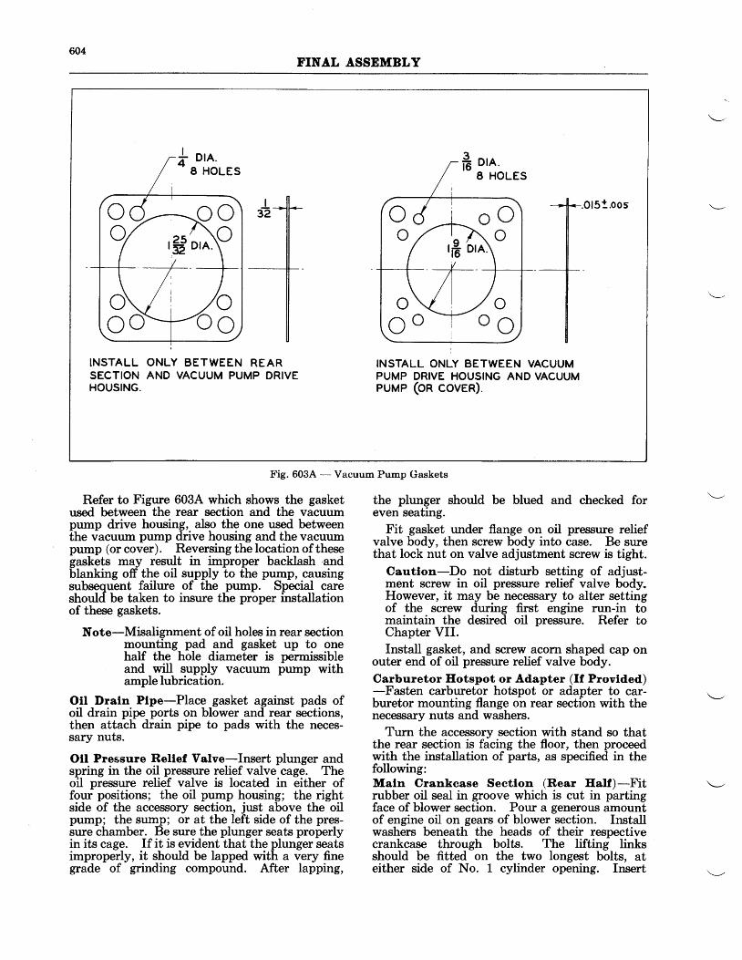
604FINAL ASSEMBLY
Refer to Figure 603A which shows the gasketused between the rear section and the vacuumpump drive housing, also the one used betweenthe vacuum pump drive housing and the vacuumpump (or cover). Reversing the location of thesegaskets may result in improper backlash ,andblanking off the oil supply to the pump, causingsubsequent failure of the pump. Special careshould be taken to insure the proper installationof these gaskets.
Note-Misalignment of oil holes in rear sectionmounting pad and gasket up to onehalf the hole diameter is permissibleand will supply vacuum pump withample lubrication.
Otl Dratn Plpe-Place gasket against pads ofoil drain pipe ports on blower and rear sections,then attach drain pipe to pads with the neces-sary nuts.
Oll Pressure Rellef Valve-Insert plunger andspring in the oil pressure relief valve cage. Theoil pressure relief valve is located in either offour positions; the oil pump housing; the rightside of the accessory section, just above the oilpump; the sump; or at the left side of the pres-sure chamber. Be sure the plunger seats properlyin its cage. If it is evident that the plunger seatsimproperly, it should be lapped with a very finegrade of grinding compound. After lapping,
the plunger should be blued and checked foreven seating.
Fit gasket under flange on oil pressure reliefvalve body, then screw body into case. Be surethat lock nut on valve adjustment screw is tight.
Cautlon-Do not disturb setting of adjust-ment screw in oil pressure relief valve body,However, it may be necessary to alter settingof the screw during first engine run-in tomaintain the desired oil pressure. Refer toChapter VII.Install gasket, and screw acorn shaped cap on
outer end of oil pressure relief valve body.Carburetor Eotspot or Adapter (ff Provtded)-Fasten carburetor hotspot or adapter to car-buretor mounting flange on rear section with thenecessary nuts and washers.
Turn the accessory section with stand so thatthe rear section is facing the floor, then proceedwith the installation of parts, as specified in thefollowing:Maln Crankcase Sectlon (Rear Half )-Fitrubber oil seal in groove which is cut in partingface of blower section. Pour a generous amountof engine oil on gears of blower section. Installwashers beneath the heads of their respectivecrankcase through bolts. The lifting linksshould be fitted on the two longest bolts, ateither side of No. 1 cylinder opening. Insert
l'5toos
ilINSTALL ONLY BETWEEN REARSECTION AND VACUUM PUMP DRIVEHOUSING.
INSTALL ONLY BETWEEN VACUUMPUMP DRIVE HOUSING AND VACUUMPUMP (On cOven).
rff ore.c d r o oo , a r ^ A . o
rfi brn)
Fig. 603,4. - Vacuum Pump Gaskets
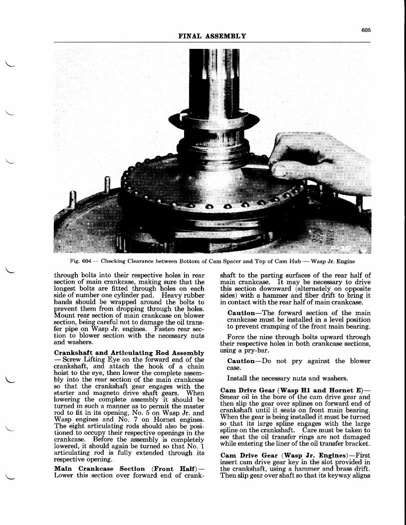
605FINAL ASSEMBLY
Fig. 604 - Checking Clearance between Bottom of Cam Spacer and Top of Cam Hub - Wasp Jr. Engine
through bolts into their respective holes in rearsection of main crankcase, making sure that thelongest bolts are fitted through holes on eachside of number one cylinder pad. Heavy rubberbands should be wrapped around the bolts toprevent them from dropping through the holes.Mount rear section of main crankcase on blowersection, being careful not to damage the oil trans-fer pipe on Wasp Jr. engines. Fasten rear sec-tion to blower section with the necessarv nutsand washers.
Crankshaft and Artlculatlng Rod Assernbly- Screw Lifting Eye on the forward end of thecrankshaft, and attach the hook of a chainhoist to the eye, then lower the complete assem-bly into the rear section of the main crankcaseso that the crankshaft gear engages with thestarter and magneto drive shaft gears. Whenlowering the complete assembly it should beturned in such a manner as to permit the masterrod to fit in its opening, No. 5 on Wasp Jr. andWasp engines and No. 7 on Hornet engines.The eight articulating rods should also be posi-tioned to occupy their respective openings in thecrankcase. Before the assembly is completelylowered, it should again be turned so that No. 1articulating rod is fnlly extended through itsrespective opening.Maln Crankcase Sectlon (Front Half )-Lower this section over forward end of crank-
shaft to the parting surfaces of the rear half ofmain crankcase. It may be necessary to drivethis section downward (alternately on oppositesides) with a hammer and fiber drift to bring itin contact with the rear half of main crankcase.
Cautlon-The forward section of the maincrankcase must be installed in a level positionto prevent cramping of the front main bearing.
Force the nine through bolts upward throughtheir respective holes in both crankcase sections,using a pry-bar.
Cautlon-Do not pry against the blowercase.
Install the necessary nuts and washers.
Carn l)rlve Gear (Wasp Ifl and Hornet E)-Smear oil in the bore of the cam drive gear andthen slip the gear over splines on forward end ofcrankshaft until it seats on front main bearing.When the gear is being installed it must be turnedso that its large spline engages with the largespline on the crankshaft. Care must be taken tosee that the oil transfer rings are not damagedwhile entering the liner of the oil transfer bracket.
Carn Drlve Gear (Wasp Jr. Engtnes)-Firstinsert cam drive gear key in the slot provided inthe crankshaft, using a hammer and brass dnift.Then slip gear over shaft so that its keyway aligns
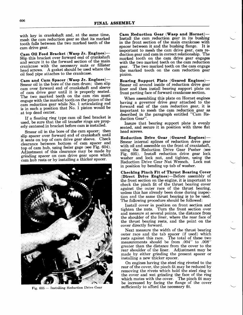
606FINAL ASSEMBLY
with key in crankshaft and, at the same time,-"rtr th"e cam reduction gear so that its markedl"otft lutt* tr"t*een the t*o marked teeth of thecam drive gear.
Cam Otl Feed Braeket (Wasp Jr. Engl+el)-Stio tt ir bracket over for*ard end of crankshaft;A il*e it to the forward section of the main"ru"["ut" with the necessary nuts or fillisterft"ua ."t"*t. A gasket shoulcl be used where theoil feed pipe attaches to the crankcase.
Carn and Cam' Spacer iWasp Jr. Englnes)-S*"ut oit in the bole of the cam drum; ther! slip"urn on"t forward end of crankshaft and sleeve;f-;fi drive gear un!il it is properly seated'The two mark-ed teeth on the cam rim must""n"e" *itft the marked tooth on the piryorl of the""il?"a"ction gear while No. 1 articulating -rodi" il r""tt a position that No. 1 piston would beat top dead center.
If a floating ring type cam oil feed bracket isused, be sure that the oil transfer tFqt are.prPp-erly centered in bracket before cam is installed'
Smear oil in the bore of the cam spacer-; thenslip spacer over forward end of crankshaft untilit
^reais on top of cam drive gear sleeve. Check
.i"uiu"." betiveen bottom of cam spager -?ndtop of cam hub, using feeler gage (see Fig. -60+).Adj".tt"ent of this clearance may Ue madg .bIsrinaine spacer on cam drive gear upon which6am hub r6sts or by installing a thicker spacer'
Cam Reductlon Gear (Wasp and Eornet)-Install the cam reduction gear in its bushingin the front section of the main crankcase withspacer between it and the bushing flange. It isimportant to mesh the cam driv_e gear,, cam_re-duction gear and cam in correct relationship. Themarked tooth on the cam drive gear engageswith the two marked teeth on the cam reductiongear. The two marked teeth on the_ cam engagethe marked tooth on the cam reduction gearpinion.
Bearlng Support Plate (Geared Englnes)-Smear oil around inside of reduction drive gearliner and then install bearing support plate onfront parting face of forward crankcase section.
When assembling this plate on Hornet engineshaving a governor drive gear attached to theforward end of the cam reduction gar, it isimportant to mesh the cam reduction gear asdescribed in the paragraph entitled "Cam Re-duction Gear".
Insure that bearing support plateseated, and secure it in position withhead screws.
is evenlythree flat
Reductlon Drlve Gear (Geared Englnes)-Smear internal splines of reduction drive gearwith oil and assemble on the front of crankshaft,using the Reduction Drive Gear Pusher (seeFig. 605). Install reduction drive gear lockwasher and lock nut, and tighten, using theReduction Drive Gear Nut Wrench. Lock nutin position by bending up tab of washer.
Checklng Plnch Ftt of Thrust Bearlng Cover(Direct Drlve Englnes)-Before assembly ofthe front section on the engine, it is important tocheck the pinch fit of the thrust bearing coveragainst the outer race of the thrust bearing,unless this has already been done during inspec-tion and the same thrust bearing is to be rrsed.The following procedure should be followed:
Install cover in position on front section andtighten the nuts. Turn the front section overand measure at several points, the distance fromthe shoulder of the liner, where the rear face ofthe thrust bearing rests, and the point on thecover directly forward.
Next measure the width of the thrust bearingouter race and the tab spacer (if used) whichrests against this race. The total of these twomeasurements should be from .004" to .008"greater than the distance from the cover to therear shoulder of the liner. Adjustment may bemade by either grinding the present spacer orinstalling a new thicker spacer.
On engines having the steel ring riveted to therear of the cover, the pinch fit may be reduced byremoving the rivets which hold the steel ring tothe cover and wet grinding the face of the ringwhich mates with the cover. The pinch fit maybe increased by facing the flange of the coversufficiently to afford the necessary fit.Fig. 605 - I'nstalling Reduction Drive Gear
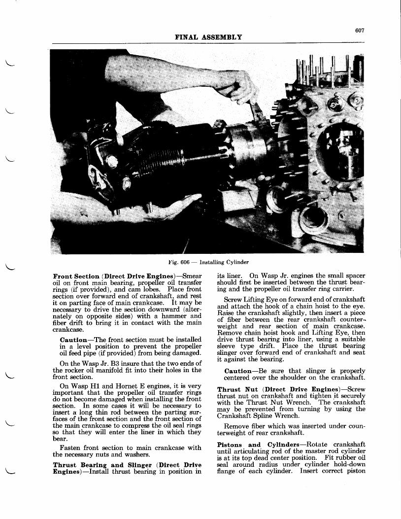
607FINAL ASSEMBLY
Fig. 606 - Installing Cylinder
Front Sectlon (Dtrect Drlve Englnes)-Smearoil on front main bearing, propeller oil transferrings (if provided), and cam lobes. Place frontsection over forward end of crankshaft, and restit on parting face of main crankcase. It may benecessary to drive the section downward (alter-nately on opposite sides) with a hammer andfiber drift to bring it in contact with the maincrankcase.
Cautlon-The front section must be installedin a level position to prevent the propelleroil feed pipe (if provided) from being damaged.
On the Wasp Jr. B3 insure that the two ends ofthe rocker oil manifold fit into theif holes in thefront section.
On Wasp H1 and Hornet E engines, it is veryimportant that the propeller oil transfer ringsdo not become damaged when installing the frontsection. In some cases it witl be necessary toinsert a long thin rod between the parting sur-faces of the front section and the front section ofthe main crankcase to compress the oil seal ringsso that they will enter the liner in which theybear.
Fasten front section to main crankcase withthe necessary nuts and washers.
Thrust Bearlng and Sllnger (Dlrect DrlveEnglnes)-Install thrust bearing in position in
its liner. On Wasp Jr. engines the small spacershould first be inserted between the thrust bear-ing and the propeller oil transfer ring carrier.
Screw Lifting Eye on forward end of crankshaftand attach the hook of a chain hoist to the eye.Raise the crankshaft slightly, then insert a pieceof fiber between the rear crankshaft counter-weight and rear section of main crankcase.Remove chain hoist hook and Lifting Eye, thendrive thrust bearing into liner, using a suitablesleeve type drift. Place the thrust bearingslinger over forward end of crankshaft and seatit against the bearing.
Cautlon-Be srrre that slinger is properlycentered over the shoulder on the crankshaft.
Thrust Nut (Dlrect Drlve Englnes)-Screwthrust nut on crankshaft and tighten it securelywith the Thrust Nut Wrench. The crankshaftmay be prevented from turning by using theCrankshaft Spline Wrench.
Remove fiber which was inserted under coun-terweight of rear crankshaft.
Plstons and Cyllnders-Rotate crankshaftuntil articulating rod of the master rod cylinderis at its top dead center position. Fit rubber oilseal around radius under cylinder hold-downflange of each cylinder. Insert correct piston
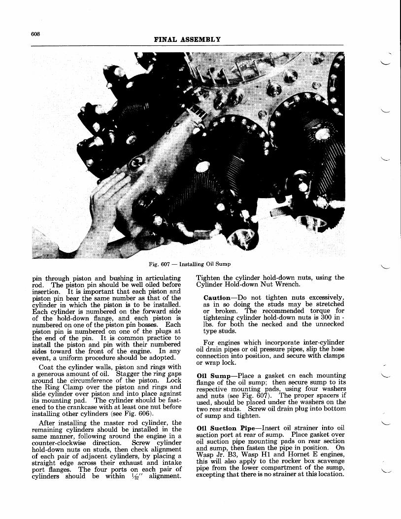
608FINAL ASSEMBLY
Fig. 607 - Installing Oil Sump
pin through piston and bushing in arJiqulatlngiod. The piston pin should be well oiled beforeinsertion. It is important that each piston andpiston pin bear the same number as that of the-ylinder in which the piston is to be installed.Each cylinder is numbered on the forward sideof the hold-down flange, and each piston isnumbered on one of the piston pin bosses. Eachpiston pin is numbered on one of the plugs atthe end of the pin. It is common practice toinstall the piston and pin with their numberedsides toward the front of the engine. In anyevent, a uniform procedure should be adopted.
Coat the cylinder walls, piston and rings witha generous amount of oil. Stagger the ring gap_saround the circumference of the piston. Lockthe Ring Clamp over the piston and rings andslide cylinder over piston and into place againstits mounting pad. The cylinder should be fast-ened to the crankcase with at least one nut beforeinstalling other cylinders (see Fig. 606).
After installing the master rod cylinder, theremaining cylinders should be installed in thesame manner, following around the engine in acounter-clockwise direction. Screw cylinderhold-down nuts on studs, then check alignmentof each pair of adjacent cylinders, by placing astraight edge across their exhaust and intakeport flanges. The four ports on each pair ofcylinders should be within Yn" alignment.
Tighten the cylinder hold-down nuts, using theCylinder Hold-down Nut Wrench.
Cautlon-Do not tighten nuts excessively,as in so doing the studs may be stretchedor broken. The recommended torque fortightening cylinder hold-down nuts is 300 in -lbs. for both the necked and the unneckedtype studs.
For engines which incorporate inter-cylinderoil drain pipes or oil pressure pipes, slip the hoseconnection into position, and secure with clampsor wrap lock.
Oll Surnp-Place a gasket cn each mountingflange of the oil sump; then secure sump to itsresp-ective mounting pads, using four washersanil nuts (see Fig. 607). The proper spacers ifused, should be placed under the washers on thetwo rear studs. Screw oil drain plug into bottomof sump and tighten.
Oll Suctlon Ptpe-Insert oil strainer into oilsuction port at rear of sump. Place gasket overoil suction pipe mounting pads on rear sectionand sump, then fasten the pipe in position. OnWasp Jr. 83, Wasp H1 and Hornet E engines,this will also apply to the rocker box scavengepipe from the lower compartment of the sump,excepting that there is no strainer at this location.
609FINAL ASSEMBLY
Cyttnder l)eflectors-Unless a shroud is usedfor cooling purposes during the run-in of anengine after overhaul, it is recommended thatthe cylinder deflectors be left off until after run-in of the engine. For complete instructions oninstalling cylinder deflectors see Chapter VIII.
Ienltlon Manlfold-Attach both front and rearsf,ielding manifolds to the main crankcase withthe necessary nuts or cap screws. On the rearmanifold, it is first necessary to disjoin the twosections before installing it on the engine. Afterthe manifold has been installed in position, thetwo parts may be joined together with the largeunion nut.
Intake Ptpes-With the necessary flange, glandnut and rubber packing in place on the intakepipe, place pipe in position and screw gland nutIoosely into the blower. Install copper gasketat cylinder intake port with the split side towardthe port, then fasten intake pipe flange to cylinderheaii with cap screw and nuts.
Cautlon-Tighten screw and nuts evenly toprevent distortion at the flange.
Tighten gland nut at blower end of pipe, usingthe Intake Pipe Nut Wrench.
Cautlon-Do not tighten excessively, as inso doing the end of the intake pipe may neckdown.
Push Rods and Covers-Wasp Jr. engines,which incorporate either on Automatic ValveLubricator or the One-Shot System, require theuse of a drilled type push rod ball end at the tap-pet ends, only, of the push rods for the followingcylinders: Inlet #L,2,3, 8, and 9 cylinders; andExhaust #L, 2, 3, 4, 7, 8, and 9 cylinders. Plaintype ball ends should be used on both ends of theremaining push rods.
Smear oil on the ball ends of each push rod, andthen insert push rod in cover. Rotate crankshaftuntil tappet which actuates push rod to be in-stalled is fully receded in its respective guide.Depress rocker arm with the Rocker Arm De-pressor, and fit push rod and cover into properposition. Be sure that push rod is properlymarked and inserted in its correct position withrespect to the cylinder number. Tighten glandnut on each end of cover using Push Rod GlandNut Wrench. The gland nut at the tappet endof the cover should be tightened first.
Cautlon-Tighten these nuts snugly but notexcessively.
Prlmer Llnes and Cyllnder Otl Feed Plpes-Screw primer line distributor into top of blowersection and attach necessary primer lines. Con-nect primer lines to their respective elbows atthe cylinder heads. On Wasp Jr. B enginm,having a valve lubricator system, attach the
pressure pipe to the tee connection at No. 1cylinder and to the oil outlet at the lubricatorpump on the rear section.
Checklng Valve Tlmlng-Fit Timing Pointerover propeller shaft of direct drive engine and toreduction drive gear of geared engines.
With CrankshaftWrench, turn crankshaft anti-clockwise until the piston in No. 1 cylinder is atthe exact top dead center of the compressionstroke (both valves closed). Set the clearancebetween adjusting screw ball and valve stem to.060" for Wasp Jr. and Wasp engines and .078"for Hornet engines, for both inlet and exhaustvalves in No. L cylinder. To perform this opera-tion, use Valve Adjusting Screw Wrench andfeeler gage.
Turn crankshaft anti-clockwise nearly onerevolution until pointer is near inlet open mark(I.O.) on front section of direct drive enginesand bearing support plate of geared drive engines,then insert .0015" feeler gage between adjustingscrew ball and stem of No. 1 inlet valve. TapCrankshaft Wrench in an anti-clockwise directionuntil a slight pressure is exerted against feeler,or until inlet valve is just ready to open, then noteposition of pointer with respect to inlet openingmark.
Turn cranlcshaft anti-clockwise until pointerpasses exhaust valve closing mark (8.C.), theninsert .0015" feeler gage between adjusting screwball and stem of number one exhaust valve.Next turn crankshaft clockwise until pointer isin a vertical position. Tap wrench in an anti-clockwise direction until pressure on feeler beginsto release, then note position of pointer with re-spect to exhaust closing mark.
The following table contains the opening andclosing positions of the valves.
Inlet Opens Inlet Closes Exhaust Opens Erhaust Closes(in degrees (in degrees (in degrees (in degrees
Engine before top after bottom before bottom after topTipe center) center) center) center)
waspJr. 26"^E- zsir. zri n. srl l .wil- ie?n. rcir* zrl n. eri r,.Hornet 20" E. 77" L. 76" E. 21" L.
Adjustrrrent of Valve Clearances-The valveclearances are adjusted in a sequence which con-forms to the firing order of the cylinders, (i.e. 1,3 , 5 , 7 , 9 , 2 , 4 , 6 , 8 ) .
Turn the crankshaft anti-clockwise until bothvalves of cylinder No. 1 are closed and the pistonis at the exact top dead eenter of the compres-sion stroke. Insert a .010" feeler gage betweenthe valve tip and the adjusting screw ball.Loosen lock nut and back off or turn down onvalve clearance adjusting screw, using ValveAdiusting Screw Wrench, until .010" clearanceis obtained. Retighten the lock nut, being care-ful not to turn the adjusting screw.
Cautlon-When the adjusting screw lock nutsare tightened an excessive pressure should notbe exerted as such will pre-load the adjusting
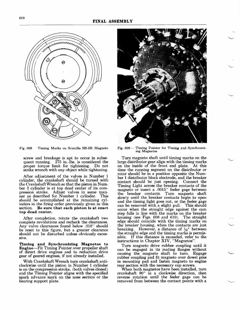
610FINAL ASSEMBLY
Fig. 608 - Timing Marks on Scintilla SB-9R Magneto
screw and breakage is apt to occur in subse-quent running. 275 in.-lbs. is considered theproper torque limit for tightening. Do notstrike wrench with any object while tightening.
After adjustment of the valves in Number 1cylinder, the crankshaft should be turned withthe CrankshaftWrench so that the piston in Num-ber 3 cylinder is at top dead center of its com-pression stroke. Adjust valves in same man-ner as described for Number 1 cylinder. Thisshould be accomplished at the remaining cyl-inders in the firing order previously given in thissection. Be sure that each plston ls at exacttop dead center.
After completion, rotate the crankshaft twocomplete revolutions and recheck the clearances.Any valve clearances found below .010" shouldbe reset to this figure, but.a greater clearanceshould not be disturbed unless obviously exces-sive.
Tfunlng and Synchronlzlng Magnetos toEnglne-Fit Timing Pointer over propeller shaftof direct drive engines and to reduction drivegear of geared engines, if not already installed.
With Crankshaft Wrench turn crankshaft anti-clockwise until the piston in Number 1- cylinderis on the compression stroke, (both valves closed)and the Timing Pointer aligns with the specifiedspark advance mark on the nose section or thebearing support plate.
Fig. 609 - Timiig Pointer for Timing and Synchroniz-ing Magnetos
Turn magneto shaft until timing marks on thelarge distributor gear align with the timing markson the inside of the front end plate. At thistime the running segment on the distributor orrotor should be in a position opposite the Num-ber 1 distributor block electrode, and the breakercontact should be just opening. Connect theTiming Light across the breaker contacts of themagneto or insert a .0015" feeler gage betweenthe breaker contacts. Turn magneto shaftslowly until the breaker contacts begin to openand the timing light goes out, or the feeler gagecan be removed with a slight pull. This shouldoccur when the straight edge against the camstep falls in line with the marks on the breakerhousing (see Figs. 608 and 610). The straightedge should coincide with the timing marks onthe breaker housing, when the contacts are justbreaking. However, a distance of Ysz" betweenthe straight edge and the timing marks is permis-sible. If this distance is exceeded, refer to theinstructions in Chapter XIV, "Magnetos".
Turn magneto drive rubber coupling until itcan be engaged in its mating flanges withoutcausing the rnagneto shaft to turn. Engagerubber coupling and fit magneto over dowel pinsin mounting pad and fasten magneto to enginerear section with the necessary cap screws.
When both magnetos have been installed, turncrankshaft 90' in a clockwise direction, thenreverse rotation until the feeler gage can beremoved from between the contact pdints with a
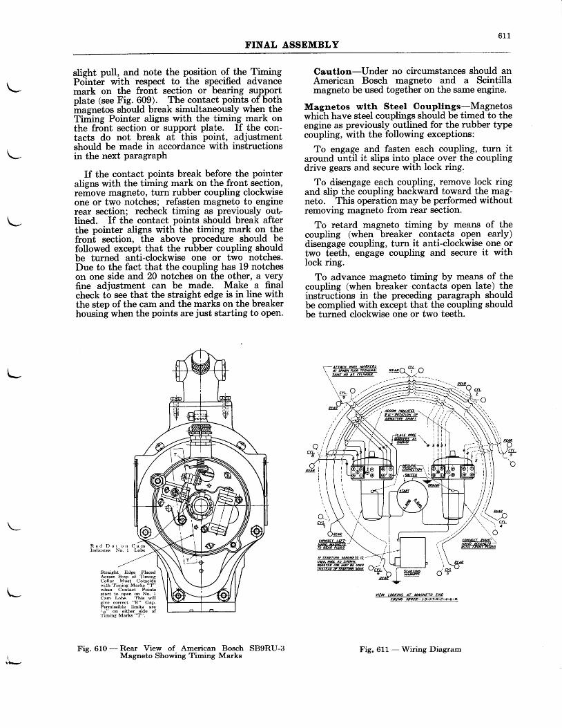
6 1 1FINAL ASSEMBLY
\-
\-
t-
slieht pull, and note the position of the TimingPo-intei with respect to the specified advancemark on the front section or bearing supportplate (see Fig. 609). The contact points of bothmagnetos should break simultaneously when theTiming Pointer aligns with the timin_g- mark onthe front section or support plate. If the con-tacts do not break at this point, adjustmentshould be made in accordance with instructionsin the next paragraph
If the contact points break before the pointeraligns with the timing mark on the front section,remove magneto, turn rubber coupling clockwiseone or two notches; refasten magneto to enginerear section; recheck timing as previously outIined. If the contact points should break afterthe pointer aligns with the timing mark o_n- thefront section, the above procedure should befollowed except that the rubber coupling shouldbe turned anti-clockwise one or two notches.Due to the fact that the coupling has 19 notcheson one side and 20 notches on the other, a veryfine adjustment can be made. Make a finalcheck to see that the straight edge is in line withthe step of the cam and the marks on the breakerhousing when the points are just starting to open.
R e d D o t o n C a mIndicates No. 1 Lobe
Cautlon-Under no circumstances should anAmerican Bosch magneto and a Scintillamagneto be used together on the same engine.
Magnetos wtth Steel Coupllngs=Mqgnetoswhich have steel couplings should be timed to theengine as previously outlined for the rubber typecoupling, with the following exceptions:
To engage and fasten each coupling, turn itaround until it slips into place over the couplingdrive gears and secure with lock ring.
To disengage each coupling, remove lock ringand slip the coupling backward toward the mag-neto. . This operation may be performed withoutremoving magneto from rear section.
To retard magneto timing by means of thecoupling (when breaker contacts open early)disengage coupling, turn it anti-clockwise one ortwo teeth, engage coupling and secure it withlock ring.
To advance magneto timing by means of thecoupling (when breaker contacts open late) theinstructions in the preceding paragraph shouldbe complied with except that the coupling shouldbe turned clockwise one or two teeth.
Straight Edge PlacedAcros Step of TimingCollar Muet Coincidewith Timing Marks "T"
I when Contact Points
\- B'i* f"f,B."" &i,I';,figive correct "E" Gap.Permisible limits arel;!" on either side ofTiming Marks "T".
YIEW L@KINO AT UAaNE|O ENOFIRINO OPzEP- l-3-5-7-9-2-1-6-A
Fie. 610 - Rear View of American Bosch SB9RU-3- Magneto Showing Timing Marks
Fig. 611 - Wiring Diagram
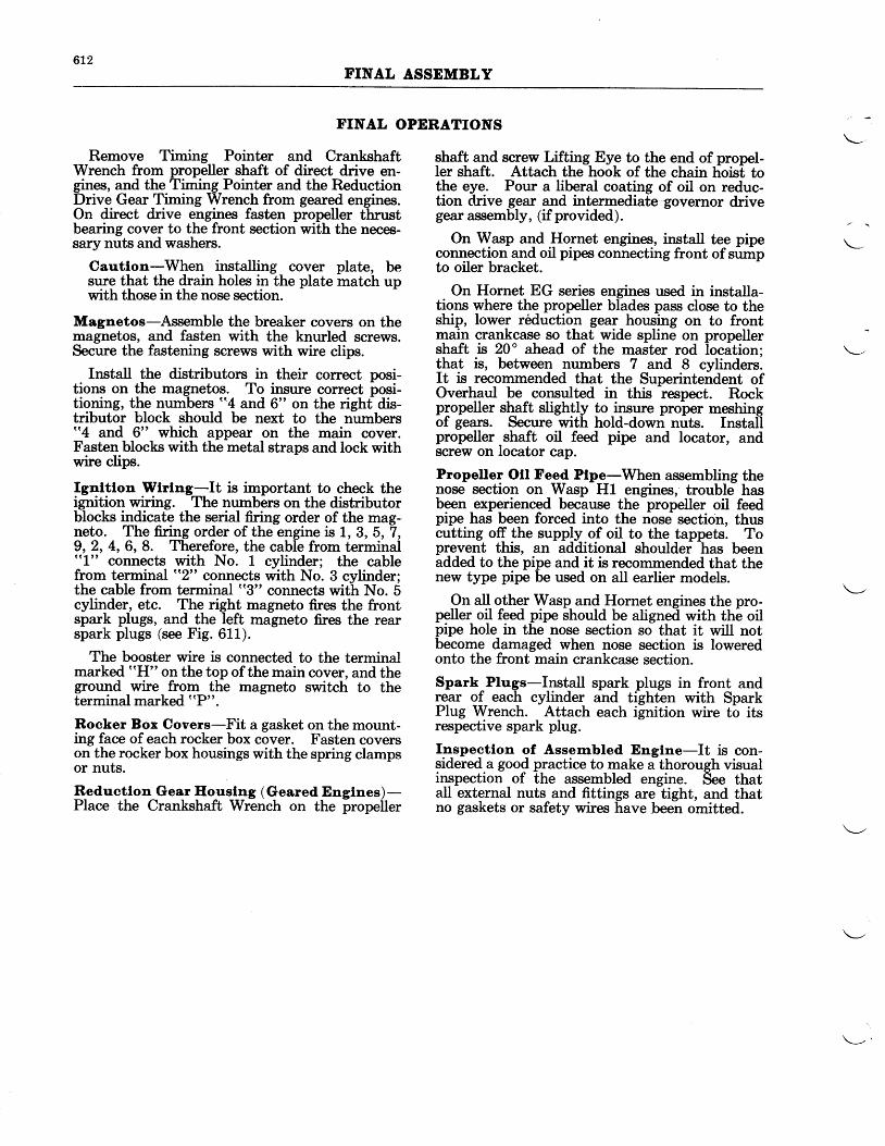
6L2T.INAL ASSEMBLY
FINAL OPERATIONS
Remove Timing Pointer and CrankshaftWrench from propeller shaft of direct drive en-gines, and the Timing Pointer and the ReductionDrive Gear Timing Wrench from geared engines.On direct drive engines fasten propeller thrustbearing cover to the front section with the neces-sary nuts and washers.
Cautlon-When installing cover plate, besure that the drain holes in the plate match upwith those in the nose section.
Magnetos-Assemble the breaker covers on themagnetos, and fasten with the knurled screws.Secure the fastening serews with wire clips.
Install the distributors in their correct posi-tions on the magnetos. To insure correct posi-tioning, the numbers "4 and 6" on the righf dis-tributor block should be next to the numbers"4 and 6" which appear on the main cover.Fasten blocks with the metal straps and lock withwire clips.
Ignltlon Wrlng-It is irnportant to check theignition wiring. The numbers on the distributorblocks indicate the serial firing order of the mag-neto. The firing order of the engine is 1, 3, 5,7,9,2, 4, 6, 8. Therefore, the cable from terminal((1" connects with No. 1 cylinder; the cablefrom terminal "2" connects with No. 3 cylinder;the cable from terminal "3" connects with No. 5cylinder, etc. The right magneto fires the frontspark plugs, and the left magneto fires the rearspark plugs (see Fig. 611).
The booster wire is connected to the terminalmarked ((H" on the top of the main cover, and theground wire from the magneto switch to theterminal marked ttP".
Rocker Box Covers-Fit a gasket on the mount-ing face of each rocker box cover. Fasten coverson the rocker box housings with the spring clampsor nuts.
Reductlon Gear Eouslng (Geared Englnes)-Place the Crankshaft Wrench on the propeller
shaft and screw Lifting Eye to the end of propel-ler shaft. Attach the hook of the chain hoist tothe eye. Pour a liberal coating of oil on reduc-tion drive gear and intermediate governor drivegear assembly, (if provided).
On Wasp and Hornet engines, install tee pipeconnection and oil pipes connecting front of sumpto oiler bracket.
On Hornet EG series engines used in installa-tions where the propeller blades pass close to theship, lower reduction gear housing on to frontrnain crankcase so that wide spline on propellershaft is 20" ahead of the master rod
-location;
that is, between numbers 7 and 8 cylinders.It is recommended that the Superintendent ofOverhaul be consulted in this respect. Rockpropeller slgft slighlly to jnsure proper meshingof gears. Secure with hold-down nuts. Instaiipropeller shaft oil feed pipe and locator, andscrew on locator cap.
Propeller Otl Fe_ed Ptpe-When assembling thenose section on Wasp H1 engines, trouble hasbeen experienced because the propeller oil feedpipe has been forced into the nose section, thuscutting off the supply of oil to the tappets. Toprevent this, an additional shouldei has beenadded to the pipe and it is recommended that thenew type pipe be used on all earlier models.
On all other Wasp and Hornet engines the pro-peller oil feed pipe should be aligned with the oilpipe hole in the nose section so that it will notbecome damaged when nose section is loweredonto the front main crankcase section.
Spark Plugs-Install spark plugs in front andrear of each cylinder and tighten with SparkPlug Wrench.
-Attach each i[nition wire tb its
respective spark plug.
I4spectlon of Assernbled Engtne-It is con-sidered a good practice to make a thorough visuali{rgpection of the assembled engine. See thatall external nuts and fittings are tight, and thatno gaskets or safety wires have been omitted.
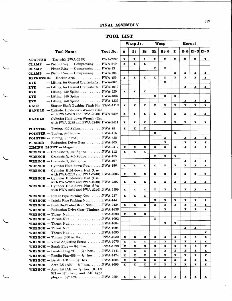
613FINAL ASSEMBLY
TOOL LIST
ADAPTER _
CLAMP\- cLAMP
CLAMP
DEPRESSOR
Tool Nanre
(Use with PWA-2239) ..
Tool No.
.PWA-2240
DYEDYEDYEDYEDYEGAGEEANDLE
Piston Ring - Compressing. . . . .PWA-249
PistonRing - Compressing... . .PWA-13
Piston Ring .- Compressing. . . . .PWA-184- R o c k e r A r m . . . . . P W A - 4 5 5
Lifting, for Geared Crankshafts. . PWA-662
Lifting, for Geared Crankshafts. . PWA-1079-Lifting, #30 Spline. . . . . . . .PWA-520- Lifting, #40 Spline. . . . . . . .PWA-1332-Lif t ing, #50 Spline. . . . . . . .PWA-1333- Starter Shaft Bushing Flush Pin. TAM-1113- Cylinder Hold-down Wrench (Use
with PWA -2299 and PWA-2240) . PWA-2398
EANDLE - Cylinder Hold-down Wrench (Usewith PWA-2239 and PWA-2240). PWA-241L
POINTDR -T im ing , 130 Sp l i ne . . . . . . . .PWA-85
POINTER -T iming, 140 Spl ine. . . . . . . .PWA-115
POINTER -T iming, (3 :2 red. ) . ' .PWA-535
PUSEER - Reduction Drive Gear. . . .PWA-465
T IMING L IGET-Magne to . . . . .PWA '24L7
WRENCE - Crankshaf t , #30 Spl ine . . . .PWA-112
WRENCE - Crankshaft, #40 Spline .. . .PWA-155
WRDNCE - Crankshaft, #50 Spline .. . .PWA-197
WRENCE - Cylinder Hold-down Nut . . PWA-186
WRENCE - Cylinder Hold-down Nut (Usewith PWA-2239 and PWA-2240). PWA-2006
WRENCE - Cylinder Hold-down Nut (Usewith PWA -2239 and PWA-2240) . PWA-2397
WRDNCE - Cylinder Hold-down Nut (Usewith PWA-2239 and PWA-2240). PWA-2399
WREITCE - Intake Pipe Packing Nut . . PWA-237
WRDNCE - Intake Pipe Packing Nut . . PWA-144
WRENCE - Push RodTube Gland Nut. . . . ' .PWA'2434
WREITCE - Reduction Drive Gear (Timing) . .PWA-1636
WRENCE - Thrust Nut. . . .PWA-1093
WRENCE-Th rus t Nu t . . . .PWA-1092
\PRENCE -Thrust Nut . . . .PWA-1084
WRDNCE - Thrust Nut. . . .PWA-1094
WRENCE - Thrust Nut. . . .PWA-1095
WRENCE - Torque (600 in. lbs.) . PWA-2239
WRDNCE - Valve Adjusting Screw . . . .PWA-1075
WRDNCE - Spark Plug - ry*" hex. . . .PWA-1398
WRENCE - Bendix Plug 7B - V8" hex.. . . . .PWA-1441
WRENCE - Bend i xP lug6S6 - 14 " hex . . . . . .PWA- I474
WRDNCE - BendixLS1O - r ' /8" hex.. . .PWA-1684
WRDNCE - Aero LS L,4'8 - ,4" hex. . . PWA-1696
WRDNCE - Aero LS 3AB - 94" hex. BG LS321- !,4" hex., and AN tYPeplugs - ,4" hex... . -PWA-2254
Wasp Jr. Wasp Ilornet
B 82 B8 EI ET. G D E . G 82. GI D3. G
x x x x x x x x xx x x
x xx x x x
x x x x x x x x xx
x x xx x x
x x xx x x
x x x x x x x x x
x x x x x x x x x
x x x x x x x x x
x x xx x
x x x xx x x x
x x x x x x x x xx x x
x x xx x x
x x x x x x x x x
x x x x x x x x x
x x x x x x x x x
x x x x x x x I x
x x xx x x x x x
x x x x x x x x I
x x x xx x x
xx x
x xx
x x x x x x x x xx x x x x x x x xx x x x x x x x xx x x x x x x x xx x x x x x x x xx x x x x x x x xx x x x x x x x x
x x x x x x x x I
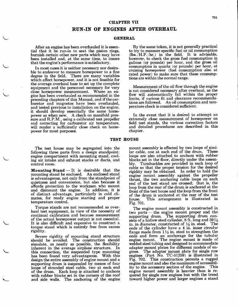
701
CIIAPTER VII
RUN-IN OF ENGINES AFTER OVERHAUL
GENERAL
After an engine has been overhauled it is essen-tial that it be run-in to seat the piston rings,burnish certain other new parts which may havebeen installed and, at the same time, to insurethat the engine's performance is satisfactory.
In most cases it is neither necessary nor desira-ble to endeavor to measure horsepower to a finedegree in the field. There are many variableswhich affect horsepower, and it is not feasible forthe average overhaul base to set up the completeequipment and the personnel necessary for veryclose horsepower measurement. Where an en-gine has been overhauled as recommended in thepreceding chapters of this Manual, and if the car-buretor and magnetos have been overhauled,and tested previous to installation on the engine,it should develop essentially the same horse-power as when new. A check on manifold pres-sure and R.P.M., using a calibrated test propellerand correcting for carburetor air temperature,will render a sufficiently close check on horse-power for mnst purposes.
TEST
The test house may be segregated into thefollowing three parts from a design standpoint:engine compartment with mounting stand, cool-ing air intake and exhaust stacks or ducts, andcontrol room.
Mountlng Stand - It is desirable that themounting stand be enclosed. An enclosed standis advanfageous, not only from the standpoint ofquietness and convenience, but also because itaffords protection to the workmen who mountand dismount the engine. In addition, it isof distinct advantage, particularly in cold cli-mates, for ready engine starting and propertemperature control.
Torque stands are not recommended as over-haul test equipment, in view of the necessity ofcontinual calibration and because measurementof the actual horsepower output is not essential.It is also difficult and expensive to construct atorque stand which is entirely free from excessrigidity.
Severe rigidity of mounting stand structureshould be avoided. The construction shouldsimulate, as nearly as possible, the flexibilityinherent in the average airplane structure. Inthis connection, the suspended type mountinghas been found very advantageoust. With thisdesign the entire assembly of engine mount 4qd asupporting drum is suspended by means o{ fburIoops of slranded steef cable, two at each endof [he drum. Each loop is attached to anchorswith rubber blocks set in the corners of the roofand side walls. The anchoring of the engine
By the same token, it is not generally practicalto tiy to measure specific fuel or oil consumptlgn(lbs. /H.P . /br.) in
- the field. It is advisable,
however, to check the grosst fuel consumption ingallons (or pounds) pei hour, and the gross oilconsumption in quarts (or pounds) per ho_ur, atcruising horsepower (fuel consumption also atrated power) to make sure that these consump-tions are within the normal range.
Measurement of the oil flow through the engineis not considered necessary after overhaul, as theflow will automatically fall within the properlimits, if various fit and clearance recommenda-tions are followed. An oil constumption and tem-perature check is considered sufficient.
In the event that it is desired to attempt anextremely close measurement of horsepower onfield test stands, the various correction factorsand detailed procedures are described in thischapter.
HOUSE
mount assembly is effected by two loops of simi-lar cable, one at each end of the drurrr. Theseloops are also attached to anchors with rubberblo-cks set in the floor, directly under the assem-bly. Turnbuckles are provided in each loop ofcable so that the propel tension for the desiredrigidity may be obtained. In order to hold theengine mount assembly against the propelle-rthiust, the two anchoring cable loops on eachend of the test stand are crossed; that is, theloop from the rear of the drum is anchored at thefront of the test house and the loop from the frontof the drum is anchored at the rear of the testhouse. This arrangement is illustrated inFig. 701.
The engine mount assembly is constructed intwo parts - the engine mount prope-r and thesupporting drum. The supportin-g drum- con-sists of a liollow steel cylinder, 8 ft. long andS9thin. in diameter, constructed of r/z in. steel. Theends of the cylinder have a 4 in. inner circularflange made from lft in. steel to strengthen theends and form an anchorage for the tubularengine mount. The engine mount is made ofwelded steel tubing and designed to accommodateadapter mount plites for di-fferent models of en-grnes. The adapter mount plate for single rowengines (Part No. TC-51259) is illustrated inFit. 702. This construction per-it.- a ruggg.dengrne mount and also the maximum of accessibil-itf to the accessory sggtio.n of the engine. Thisengine mount assembly is heavier than is re-quired for single row engines but with the trendtbward highei power an-d larger engines a stand\_
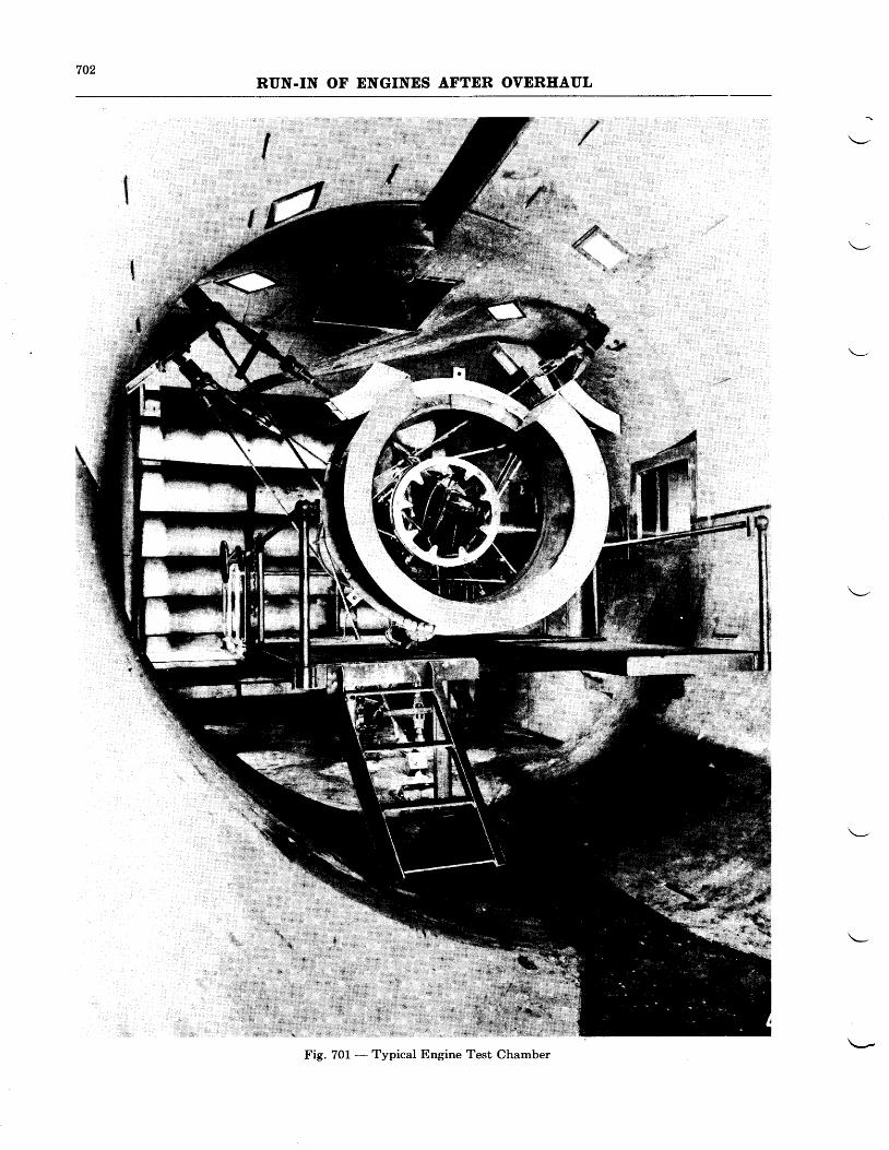
702RUN-IN OF ENGINES AFTER OVEREAUL
Fig. 701 - Typical Engine Test Chamber
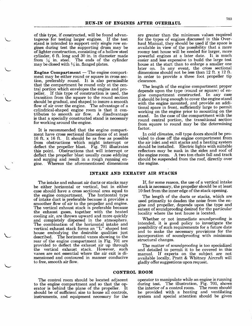
703RUN.IN OF ENGINES AFTER OVERHAUL
of this type, if constructed, will be found advan-tageous for testing larger engines. If the teststand is intended to support only single row en-grnes during test the supporting drum may beof lighter construction, consisting of a hollow steelcylinder, 6 ft. long and 30 in. in diameter madefrom % in. steel. The ends of the cylindermay be closed with Yain. flanged plates.
Englne Cornpartrnent - The engine compart-ment may be either round or square in cross sec-tion, preferably round. It is also permissiblethat the compartment be round only at the cen-tral portion which envelopes the engine and pro-peller. If this type of construction is used, thetransition from the square to the round sectionshould be gradual, and shaped to insure a smoothflow of air over the engine. The advantage of acylindrical-shaped engine room is that it con-tributes to smooth air flow. A disadvantageis that a specially constructed stand is necessaryfor working around the engine.
It is recommended that the engine compart-ment have cross sectional dimensions of at least16 ft. x 16 ft. It should be as free as possiblefrom obstructions which might interrupt ordeflect the propeller blast. Fig. 701 illustratesthis point. Obstructions that will interrupt ordeflect the propeller blast usually cause eddyingand surging and result in a rough running en-gine. Whereas the aforementioned dimensions
INTAKE AND EXHAUST AIR STACKS
The intake and exhaust air ducts or stacks maybe either horizontal or vertical, but in eithercase should have a cross sectional area equal tothe engine compartment. The horizontal typeof intake duct is preferable because it provides asmoother flow of air to the propeller and engine.The vertical exhaust stack is preferable becausethe exhaust gases, together with the heatedcooling air, are thrown upward and more quicklyand completely dispersed in the atmosphere.The combination of the horizontal intake andvertical exhaust stack forms an "L" shaped testhouse embodying the desirable qualities justdescribed. The horizontal vanes showing to therear of the engine compartment in Fig. 70I areprovided to deflect the exhaust air up throughthe vertical exhaust stack. However, suchvanes are not essential where the air exit is di-mensioned and contoured in manner conduciveto free, smooth air flow.
CONTROL
The control room should be located adjacentto the engine compartment and so that the op-erator is behind the plane of the propeller. Itshould be of sufficient size to house all controls,instruments, and equipment necessary for the
are greater than the minimum values requiredfor the types of engines discussed in this Over-haul Manual, they should be used if the space isavailable in view of the possibility that a moreroomy test house will be needed for larger, morepoweiful engines at a later date. It is mucheasier and less expensive to build the large testhouse at the start than to enlarge a smaller onelater on. In any event, the crbss sectionaldimensions should not be less than L2 ft. x 12 ft.in order to provide a three foot propeller tipclearance.
The length of the engine compartment properdepends upon the type (round or square) of en-gine compartment constructed. In any caseil should be long enough to cover the engine standwith the engine mounted, and provide an addi-tional space-in front, sufficiently large to permitworking on the engine prior to mounting on thestand.
- In the case of the compartrhent with the
round central portion, the transitional sectionfrom square to round may be the determiningfactor.
In cold climates, roll type doors should be pro-vided to close off the engine compartment fromthe air inlet and exit stacks and a heating systemshould be installed. Electric liehts with suitablereflectors may be sunk in the iides and roof ofthe engine room. A two ton chain fall and trackshould be suspended from the roof, directly overthe engine.
If, for some reason, the use of a vertical intakestack is necessary, the propeller should be at least10 feet from the inner edge of the stack opening.
The length of the ducts or stacks, which areused primarily to deaden the noise from the en-gine and propeller, depends upon the type andextent of soundproofing desired for the particularIocality where the test house is located.
Whether or not immediate soundproofing isintended, it is good policy to investigate thepossibility of such requirements for a future dateand to make the necessary provisions for theincorporation of soundproofing with minimumstructural changes.
The matter of soundproofing is too specializedand detailed to permit it to be covered in thismanual. If experts on the subject are notavailable locally, Pratt & Whitney Aircraft willgladly offer suggestions upon request.
ROOM
operator to manipulate while an e:rgine is runningduring test. The illustration, Fig. 703, showsthe inlerior of a control room. The room shouldbe provided with a heating and ventilatingsystem and special attention should be given
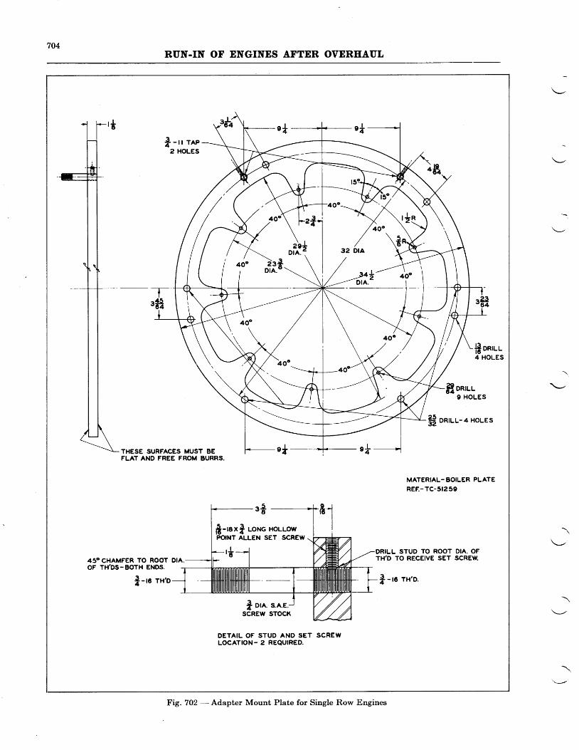
704RUN.IN OF ENGINES AFTER OVEREAUL
f - r r ree2 HOLES
f onn-r-9 HOLES
tt onruu-4 HoLEs
THESE SURFACES MUST BEFLAT AND FREE FROM BURRS.
MATERIAL-BOILER PLATEREE-TC-5t259
-.* ______*t-8
fi-raxI uor.rc HoLLorv IPOINT ALLEN SET SCREW \n-,*--l w DRILL STUD TO ROOT DIA. OF
TH,D TO RECEIVE SET SCREIV.45O CHAMFER TO ROOT DIA.OF TH,DS.BOTH ENDS.
jl-ro rx'o | -ro rx'o.
I ore. s.A.E.SCREW STOCK
DETAIL OF STUD AND SET SCREWLOCATION- 2 REQUIRED.
Fig,.7O2 - Adapter Mount Plate for Single Row Engines
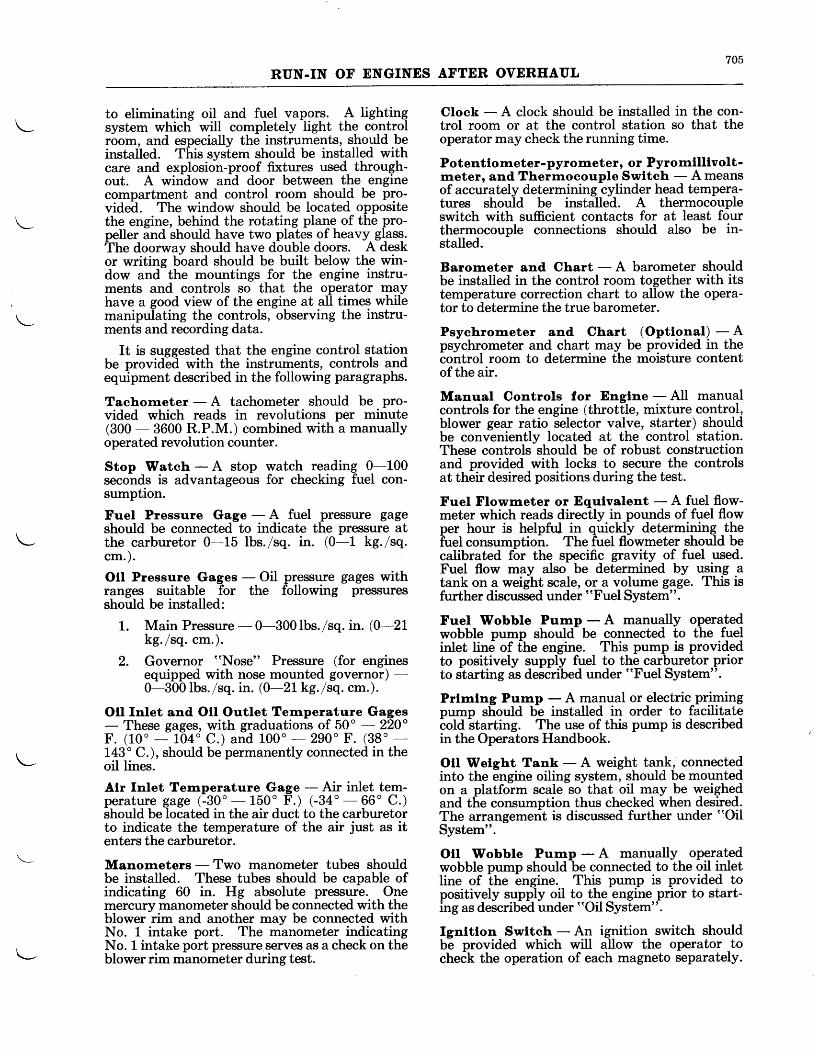
705RUN.IN OF ENGINES AFTER OVEREAUL
to eliminating oil and fuel vapors. A lightingsystem which will completely light the controlrbom, and especially the instruments, shogld beinstalled. This system should be installed withcare and explosion-proof fixtures used through-out. A window and door between the enginecompartment and control room should be pro-vided. The window should be located oppositethe engine, behind the rotating plane of the pro-peller and should have two plates of heavy glass.The doorway should have double doors. A deskor writing board should be built below the win-dow and the mountings for the engine instru-ments and controls so that the operator mayhave a good view of the engine at all times whilemanipulating the controls, observing the instru-ments and recording data.
It is suggested that the engine control stationbe provided with the instruments, controls andequipment described in the following paragraphs.
Tachometer - A tachometer should be pro-vided which reads in revolutions per minute(300 - 3600 R.P.M.) combined with a manuallyoperated revolution counter.
Stop Watch - A stop watch reading 0-100seconds is advantageous for checking fuel con-sumption.
Fuel Pressure Gage - A fuel pressure gageshould be connected to indicate the pressure atthe carburetor 0-15 lbs./sq. in. (0-1 kg./sq.cm.) .
Oll Pressure Gages - Oil pressure gages withranges suitable for the following pressuresshould be installed:
1. Main Pressure - 0-300 lbs. /sq. in. (0-21kg. /sq.cm.) .
2. Governor "Nose" Pressure (for enginesequipped with nose mounted governor) -0-300Ibs./sq. in. (0-21 kg./sq. cm.).
Oil fnlet and Otl Outlet Ternperature Gages- These gages, with graduations of 50' - 220"F. (10 ' - 104 ' C.) and 100' - 290" F. (38 ' -143' C.), should be permanently connected in theoil lines.
Alr Inlet Temperature Gage - Air inlet tem-perature gage (-30'- 150' F.) (-34'- 66" C.)should be located in the air duct to the carburetorto indicate the temperature of the air just as itenters the carburetor.
Manometers - Two manometer tubes shouldbe installed. These tubes should be capable ofindicating 60 in. Hg absolute pressure. Onemercury manometer should be connected with theblower rim and another may be connected withNo. 1 intake port. The manometer indicatingNo. l intake port pressure serves as a check on theblower rim manometer during test.
Clock - A clock should be installed in the con-trol room or at the control station so that theoperator may check the running time.
Potentiometer-pyrorneter, or Pyromllllvolt-rneter, and Thermocouple Swltch - A meansof accurately determining cylinder head tempera-tures should be installed. A thermocoupleswitch with sufficient contacts for at least fourthermocouple connections should also be in-stalled.
Barometer and Chart - A barometer shouldbe installed in the control room together with itstemperature correction chart to allow the opera-tor to determine the true barometer.
Psychrorrreter and Chart (Opttonal) - Apsychrometer and chart may be provided in thecontrol room to determine the moisture contentof the air.
Manual Controls for Englne - All manualcontrols for the engine (throttle, mixture control,blower gear ratio selector valve, starter) shouldbe conveniently located at the control station.These controls should be of robust constructionand provided with locks to secure the controlsat their desired positions during the test.
Fuel Flowmeter or Equlvalent - A fuel flow-meter which reads directly in pounds of fuel flowper hour is helpful in quickly determining _thefuel consumption. The fuel flowmeter should becalibrated for the specific gravity of fuel used.Fuel flow may also be determined by using atank on a weight scale, or a volume gage. This isfurther discussed under "Fuel System".
FueI Wobble Pump - A manually operatedwobble pump shoulil be connected to the fuelinlet line of the engine. This pump is providedto positively supply fuel to the carburetor priorto starting as described under "FueI System".
Prlmlng Pump - A manual or electric primingpump should be installed in order to facilitatecold
-starting. The use of this pump is described
in the Operators Handbook.
OtI Wetght Tank - A weight tank, connectedinto the engiire oiling system, should be mountedon a platfoim scale so that oil may be weighedand the consumption thus checked when desired.The arrangement is discussed further under "Oil
System".
Otl Wobble Pump - A manually operatedwobble pump should be connected to the oil inletline of the engine. This pump is provided topositively supply oil to the engine prior to start-ing as described under "Oil System".
Ignltlon Swltch - An ignition switch shouldbe provided which will allow the operator tocheCk the operation of each magneto separately.
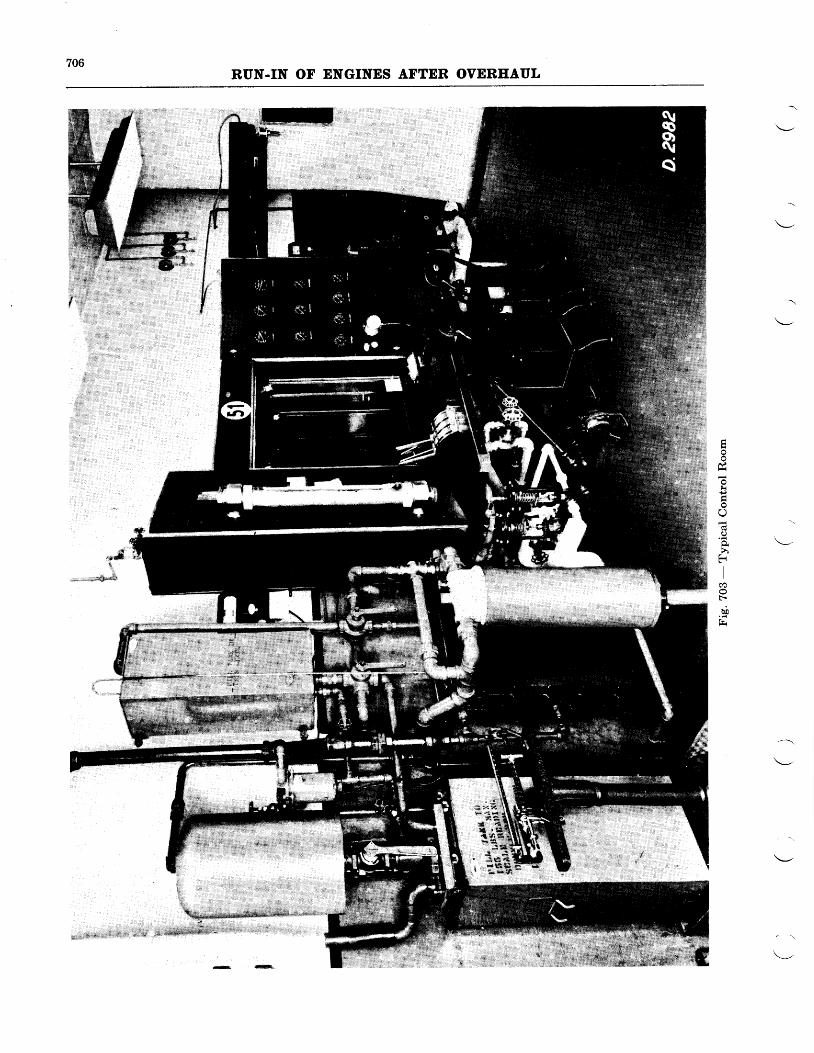
706RUN.IN OF ENGINES AFTER OVEREAUL
Fr{J
O \---h
fi
II
F-
b!f - .
"*dt
707RUN.IN OF ENGINES AFTER OVERIIAUL
The ignition switch should also have an off posi-tion which will positively cut-out the ignitionsystem of the engine.
Flre Extlngulshers - The control stationshould be provided with portable fire extinguish-ers of the Pyrene (carbon tetrachloride) andFoamite (sulphuric acid and soda) types. Apermanent COz system should be installed. Twocontrol valves for the permanent CO2 system
1. Tachometers
2. Stop Watches
3. Fuel Pressure Gages
4. Oil Pressure Gages
5. Oil Intet and Oil OutletTemperature Gages
6. Air Inlet Temperature Gages
7. Manometers
8. Clock
9. Potentiometer-pyrometer orPyromillivoltmeter, andThermocouple Switch
10. Barometer and Correction Chart
11. Psychrometer and Chart(Optional)
L2. Manual Controls for Engine
LIST OF MANUFACTURERS OF INSTRUMENTS,CONTROLS AND EQUIPMENT
should be installed at the control station, one tooperate the system in the engine compartmentand one to operate the system for the controlroom. A third valve outside the test houseshould operate both the control room and enginecompartment systems.
Following is a list of manufacturers from whomthe foregoing instruments and other equipmentmay be procured:
Blanchard Instrument Co.Cambridge, Mass., U.S.A.
A. R. & J. E. Moylan Co.264 West 64th StreetNew York City, N. Y., U.S.A.
American Ashcroft Hancock Co.Bridgeport, Conn., U.S.A.
American Ashcroft Hancock Co.Bridgeport, Conn., U.S.A.
Foxboro CompanyFoxboro, Mass., U.S.A.
Foxboro CompanyFoxboro, Mass., U.S.A.Taylor Instrument Co.Rochester, N. Y., U.S.A.
American Ashcroft Hancock Co.Bridgeport, Conn., U.S.A.Macalaster Bickwell Co.Cambridge, Mass., U.S.A.(Glass U Tubes Ya in.OD x 40 in.long for manometers)
May be obtained locally
Leeds & NorthropPhiladelphia, Pa., U.S.A.Lewis Engineering Co.Naugatuck, Conn., U.S.A.Foxboro CompanyFoxboro, Mass., U.S.A.
Taylor Instrument Co.Rochester, N. Y., U.S.A.Henry J. Green1191 Bedford AvenueBrooklyn, N. Y., U.S.A.
Taylor Instrument Co.Rochester, N. Y., U.S.A.Julien P. Friez & SonsBaltimore, Md., U.S.A.
Simmonds Aero Accessories10 Rockefeller PlazaNew York City, N. Y., U.S.A.
708RUN.IN OF ENGINES AFTER OVERHAUL
13. Fuel Flowmeters
L4. Fuel Wobble Pump
15. Priming Pump (Manual)
(Electric)
16. Oil Wobble Pump
L7. Ignition Switch
18. Fire Extinguishers
19. Scales (Fuel and Oil)
The entire test house structure may be built ofbrick and mortar, or reinforced concrete. In anyevent, the material should be non-inflammable.
Inasmuch as the engine stand supportingcables are designed for a maximum tension ofapproximately 80,000 pounds, the wall and roof
CARBURETOR AIR
The air intake duct to the carburetor shoulddraw its air from outside the test house. Itshould have a cross sectional area of at least38 sq. in. and should be as free as possible fromsharp bends or irregularities that might restrictair flow or cause turbulence. The air duct en-trance at the outside of the test house should beIocated so that dirt or foreign material will notbe taken in. A preheater, utilizing the heat oftwo or more exhaust stacks, or a steam radiator,should be provided in the system to supply pre-heated air to the carburetor. It should be possi-ble to maintain the temperature of air enteringthe carburetor at 100' F. or more under the low-est outside air temperature conditions for the
ENGINE EXEAUST SYSTEM
Fischer & PorterHatboro , Pa., U.S.A.
United Aircraft Products Inc.Dayton, Ohio, U.S.A.
The Lunkenheimer Co.Begkman St. and Waverly Ave.Cincinnati, Ohio, U.S.A.Bendix Products Div.Bendix Aviation Corp.South Bend, Indiana, U.S.A.
United Aircraft Products Inc.Dayton, Ohio, U.S.A.
Scintilla Magneto Div.Bendix Aviation Corp.Sidney, New York, U.S.A.
May be obtained locally
May be obtained locally
structure should be capable of withstanding thisstress with an adequate safety factor.
Layouts and detail construction drawings ofrecorimended test house designs are availableand may be obtained from the Pratt & WhitneyAircraft Service Department.
INTAKE SYSTEM
locality. A suitable iarburetor air temp-eratureregulaling valve should be qrovided. The pre-heating system should be so designed as to causeno apfrebiable restriction or disturbance to airflow.-
- If the preheater is located some distance
from the carb-uretor, the portion of the duct be-tween it and the carburelor should be well in-sulated to prevent loss of heat.
The entire intake system should be sufficientlystrong to withstand "backfire" pressutes, and abackfire relief valve should be located near thecarburetor.
A flexible section should be incorporated be-tween the carburetor and the fixed poltion of theintake air duct.
The use of an exhaust collector ring is notrecommended for the test stand operation. Shortstacks are desirable, in that they simplify themounting of the engine on the stand and permitthe operator to detect misfiring cylinders or im-
proper mixtures by watcbing the exhaust flame ateach cylinder. The exhaust of two or morecylinders may be conducted through a stove toprovide preheated air to the carburetor, as men-iioned under "Carburetor Air Intake System".
TEST PROPELLERS
From the standpoints of convenience, economyand cooling efficiency, a four-bladed wooden testpropeller is recommended for the average test
stand. Suitable test propellers, together withthe hubs and attaching parts, are listed in thePratt & Whitney Aircraft Parts Catalogs.
709RUN.IN OF ENGINES AFTER OVERHAUL
Since the location and characteristics of a testhouse have considerable bearing on the propellerdiameter, a test propeller, as furnished, is some-what larger in diameter than normally necessary,to permit calibration on the particular test standwhere it is to be used. A new propeller should becalibrated on a new engine, or on one that isknown to be running satisfactorily, and underatmospheric conditions which are consideredaverage for the location. This is done by trim-ming off the ends of the blades in small incre-ments until the engine will turn its normal ratedrevolutions per minute at its rated manifoldpressure.
The detailed procedure for calibrating, trim-ming and balancing is as follows:
Check the propeller for static balance withregular propeller balancing equipment. If re-balancing is necessary, trim the heavy blade, orblades, as required, referring to the related para-graphs which follow for the proper method oftrimming.
Install the propeller on an engine which isknown to be normal in every respect, and run theengine to get an indication of how much the pro-peller diameter must be decreased. Atmosphericconditions should be noted so that they can beduplicated, or necessary corrections made, duringsubsequent trial runs of the calibration procedure.
Run the engine at its normal manifold pressureand note the R.P.M.
Due to variables such as temperature, atmos-pheric pressure, shape of the test house, etc., it isimpossible to state, without trial, exactly howmuch increase in R.P.M. can be expected perinch reduction in propeller diameter on a giventest stand. The increase is usually somewherebetween 30 and 50 R.P.M., however. It issuggested that the diameter be decreased 1 in.(Yz in. per blade) for the first trimming opera-tion, then the resultant change in R.P.M. notedand used as a guide during further trimming ofthe blades.
The first step preparatory to the actual trim-ming of the blades is to rest the propeller firmlyon a bench or suitable stand and draw a line fromthe hub to the tip of each blade. This line shouldbe on the front face and along the center of theblade width.
Cautlon - To prevent damage to the fabricblade covering, when drawing this line, do notuse a hard pencil or sharp pointed tool.Next, mark off one half the desired decrease
in diameter on the line drawn along each bladeand scribe an arc from this point, the radius ofwhich is Yz the width or chord of each blade.Saw off the blade end to this line and round allsharp corners with a suitable file. Paint thenewly exposed wood with a good grade of shellacto prevent the fabric covering from becomingloose and the wood from splintering.
Upon completion of the trimming operation,
the propeller must be rebalanced before installa-tion on the engine. Make sure the hub and coneare perfectly clean, then mount the propeller on aregular propeller static balancing stand, usingproper arbors and centering cones. The balanc-ing-stand should of course be in a location freefrom vibrations and drafts. Rotate the pro-peller slowly and make sure nothing is affectingentirely free movement. Set the propeller sothat two blades are horizontal and determinewhich, if either, is the heavier. Using a drawknife or suitable fiIe, trim the end of the heavyblade, blending the edges in a round shape,holding to the radius as originally scribed. It hasbeen found that a round blade end is much lesssubject to splintering and wear than a square one.
Set the other pair of blades in a horizontalposition and repeat the procedure described forthe first pafo, then place the propeller so theblades are 45o off the vertical position. Repeatthe trimming until the propeller is in perfectstatic balance. When in true static balance, themass of one pair of blades will exactly counter-balance the mass of the other pair, even thoughit may be found that one blade may vary asmuch as ry' ir'. in length from the other threeblades to obtain this balance.
Caution - Do not use any plugs or fillers ofany kind, or additional shellac, to obtain bal-ance.As previously stated, the engine should turn
its normal rated"R.P.M. at normal rated manifoldpressure when the trimming of the test propellerhas been completed (refer to engine performancecurves for proper values), regardless of the alti-tude at which the test stand is located. It ispermissible that the manifold pressure exceednormal rated manifold pressure bV 3% at ratedspeed and that the R.P.M. vary plus or minus 50from rated R.P.M. at rated manifold pressure.
If the calibrating is done in cold weather, thepropeller should be trimmed to obtain the maxl-rnum allowed tolerance on rated manifold pres-sure and the mlnlmurn tolerance on the ratedR.P.M. Where there is a wide difference be-tween winter and summer temperatures, it isdesirable to have two test propellers, one cali-brated for winter use and the other for summerurie. Quite often the same engine will require apropeller which is up to two inches smaller forwinter use than for summer use, to obtainproper manifold pressure and R.P.M. values.
A test propeller may eventually become toosmall for a given model of engine, due to stockwhich has been removed to overcome damage(splinters, nicks, etc.) which occurred during testoperation. In such an instance, it may be foundpossible to retrim it for use on some smaller orless powerful engine.
When wooden test propellers are not in usethey should be protected from weather, particu-larly ice and snow.
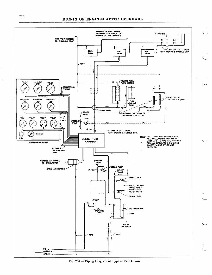
7LORUN.IN OF ENGINES AFTDR OVERHAUL
III'ER C FT.EL TA}I€OTT'TAL FOR FI.ELS OF
SES.6 OCTA}C RATIT{GS
3-WAY VALVE
\\ t' sAFETy GATE nLvE
WITH WEIG}IT T FUSbLC L|t{(
STRAilER
THI' YENT "**IIE D ? l f f r J c H f f i l I
INSTRUMENT FANEL
YOI.TE FIILrLd E?ER
OPTONAL M€THODIS OFOITAINING FI'EL FLOW
VENT COCK
FULFLO FILTERMOOEL WFDSwtTH il3CVCFILTER UNITS.
DRAIN COCK
OIL RADIATOR
rcIl,- usE r- P|PE ANO FITTINGS FORALL FUEL, WATER AND STEAMLrNEs AND tf eree ANo FrrrrNcs
" FoR tr-r- crRduttttNc otL LtNEs' EXCEPT IYHERE OTHERWISE
SPECIFIED.
OIJT3DE AN NTAKE +To cAR$nEToR
.E:
CAR8. AN
STEAMI
gATERTO SEWER
ttat ctuTcn accaaeaaTa Ld clutct
Fig. 704 - Piping Diagram of Typical Test House

7LLRUN-TN OF ENGINES AFTER OVERHAUL
COOLING
A shroud or cooling cowl should be used duringrun-in of a geared engine to insure satisfactorycooling of the cylinders. One may also be usedfor direct drive engines and should be used if it isdesired to run the engine with the cylinder airdeflectors in place. The cooling shroud takes theplace of the cowling which encircles the cylindersin a normal airplane installation. It is usuallyflared at the forward edge so as to deflect suf-ficient air over and between the cvlinders. It
FUEL
The lines feeding fuel to the engine shouldhave a minimum diameter of one inch and shouldbe free from sharp bends or restrictions of anykind. Particular care should be exercised toprovide sufficient flexibility in the piping to pre-vent line breakage or leakage. In no caseshould a trench or connecting passage below thefloor be used to carry piping or controls into theengine compartment, as fuel or gases may collectin such a passage and cause an explosion or fire.
A wobble pump with relief valve should beinstalled in the fuel system to facilitate filling thecarburetor prior to starting the engine. Aprimer, either manually or electrically operated,should be connected to the primer fitting on theengine. The priming pump may be installed
The piping of the oil system should be at leastLrl in. in diameter, and as free as possible fromfittings which tend to restrict the oil flow inorder to insure an adequate supply of oil to theengine under all temperature conditions. Par-ticular care in this regard should be given to theoil intake system.
In order to provide a positive supply of warmoil to the engine when starting in extremely coldweather, a wobble pump capable of building upat least 60 lbs./sq. in. pressure should be incor-porated in the oil intake system. Provisionshould be made for catching the cold oil that isin the oil intake line as hot oil forces the cold oilout before this line is connected just prior tostarting the engine.
The oil system should incorporate oil cleaningprovisions, such as an oil fllter in the oil returnline to the engine. An oil filter which has provedsatisfactory in test stand operations is the FulfloModel WFDS with 1136VC Type fiIter unitsmanufactured by the Commercial Filters Corpo-ration, 16 Macallen Street, Boston, Mass., U.S.A.
Both the oil pipes and the filter should be soananged that they are completely demountablefor periodic cleaning. If it is not possible to
SHROUDS
should be constructed of a heavy gage durablematerial to withstand the constant buffeting ofthe test propeller and should be mounted inde-pendent of the engine so that it may be quicklymoved to the front of the test stand to allow easyaccess in mounting and dismounting the engine,unless it is made with hinged sections as illus-trated in Fig. 70L to allow the engine to bemounted and dismounted without disturbingthe shroud.
SYSTEM
either in the control room, or directly at the en-gine.
The system should be provided with a means ofmeasuring fuel flow for the purpose of checkingconsumption. The simplest method of measure-ment is a flowmeter calibrated for the specificgravity of the fuel used. A very satisfactorymethod is to weigh the fuel and accurately timethe consumption of a given weight. Anothermethod of measurement is by means of a volumegage. When a volume gage is used, it is essentialto have an accurate check on the specific gravityof the fuel.
A suggested fuel system is shown in the pipingdiagram (Fig. 704).
OIL SYSTEM
make the pipes completely demountable, theyshould be arranged with gpadual bends, so thatthey may be cleaned easily with a swab. Thefilter should be cleaned and new filter units in-stalled after 300 hours of operation. The filtermanufacturer's instructions for renewing the filterunits should be followed.
In order to maintain oil temperatures withinthe desired range, a combination steam and waterradiator may be introduced in the oil system.Thus, by applying steam, the temperature canquickly be brought up to the desired point and byr-egulating the flow of the cooling water, it may bemaintained within the desired limits.
An accurate measurement of the oil consump-tion may be obtained by mounting the oil tankon a platform scale.
Figure 704 illustrates a suggested oil system.
Warnlng - It has been found that, in teststand operation where the oil is vented to theoutside
-air, there is sometimes a tendency for
the oil to form a high acid content. This condi-tion, if allowed to remain unchecked, can causeconosion or "washing" of the leaded masterrod bearing and possible destruction of the bear-ing. It iv particularly important that a close
7L2RUN.IN OF ENGINES AFTER OVERHAUL
check be kept upon the acid content of the oil.If the neutralization number, according toA.S.T.M. analysis method No. D 188-27 T,exceeds .3, there is danger of corrosion of theleaded master rod bearing. The oil should bechanged any time that the neutralization num-ber approaches this figure. It is good practiceto change the oil every 30 hours and, everysecond oil change or every 60 hours, to flush theoil system out with clean, new engine oil. Whenthis is done, the oil cooler should be removed andcleaned separately. Il at any time, the neu-tualization number of the oil at the end of thetest exceeds .65, the engine should be disassem-bled and the master rod bearing inspected.
The use of an acid inhibitor in the test standoil will aid in preventing high neutralizationnumbers and in prolonging the periods betweenoil drains. Thq company furnishing the oilshould be consulted in this connection.
The use of an oil cleaner in the oil system willalso serve to prolong the periods between oilchanges. Atty increase in operating time be-tweei oil changes should be approache-d griduallyas warranted by the general condition of the oiland its freedom from excessive acidity.
If there has been an engine failure on the teststand the complete oil system should be flushedout with a petroleum solvent.
Engine controls are provided by suitable bellcranks and torque tubes which extend from theengine mount assembly to the operating room.Hydraulically operated controls are being used,in some instances, with very satisfactory results.It is recommended that the streamlined memberwhich houses the operating controls, fuel lines,oil lines, and instrument wires extend from theside of the engine mount drum to the wall of thetest house on a level with the horizontal centerline of the supporting drum.
CONTROLS
INSTALLATION OF ENGINE FOR TEST
This streamlined member should be supportedfrom the wall of the engine room and should beconnected to the suppoiting drum by a flexibleleather section. Fle}ible connections should beprovided at this point in the fuel lines, oil-liJres,ind engine controls. As stated under "Fuel
System'i, the use of a trench or plt underneathtie engine is not recommended.
-In case of an-y
leakage or breakage of the fuel line,_fuel will col-lect in such a trench and any explosion or firewill be conducted directly to the control room.
The test stand should be equipped with anEngine Mounting Ring, such as Pratt & WhitneyAirbraft Part No. TC-5t259,. as illustrated inFig. 702.
The starter which is to be used should have itsproper gasket and be installed on the engine.-It
shoutii be securely fastened and the attachingnuts safety-wired to prevent it from becomingloose during run-in.
The fuel pump with its proper gasket should beinstalled on the engine with the fittings necessaryfor the connection of the fuel lines.
Lifting Sling PWA-37, in conjunction with ahoist, should be used for lifting the engine intoposition for mounting on the stand. Gearedilrive engines should have an additional rope slilgto support the "nose". This rope sling should beattached to the hook of the chain fall and passedaround under the propeller shaft to keep the cen-ter line of the engine horizontal while installingthe engine on the test stand. The engine shouldbe secured to the Engine Mounting Ring withnine bolts.
The following instrument and control connec-tions should be made:
1. Connect manometer line to blower rim formeasuring manifold pressure (absoluteblower rim pressure to be used as manifoldpressure in determining horsepower).
2. Connect manorneter line to No. 1 inlet port,also for measuring manifold pressure.(Optional)
3. Connect the tachometer.
4. Connect the throttle control.
5. Connect the mixture control.
6. Connect main oil pressure gage line to theconnection at the upper left side of the rearsection.
7. Install propeller governor cover Part No.26646 on Wasp and Hornet engines havingprovision for such on the nose section.
8. Connect pressure gage line to oil passage in"nose" section. Thfu connection is locatedto the right of the governor mounting -Pgd'as viewed from the front of direct driveWasp engines. On geared Hornet enginesthe cbnndction is made at the boss on top ofthe reduction gear housing.
9. Connect manual control to the two-positionpropeller control valve for engines soequipped.
10. Connect fuel line to the engine fuel pumpand to the carburetor.
11. Connect fuel relief valve (if not integral withfuel pump) in fuel inlet line to carburetor.
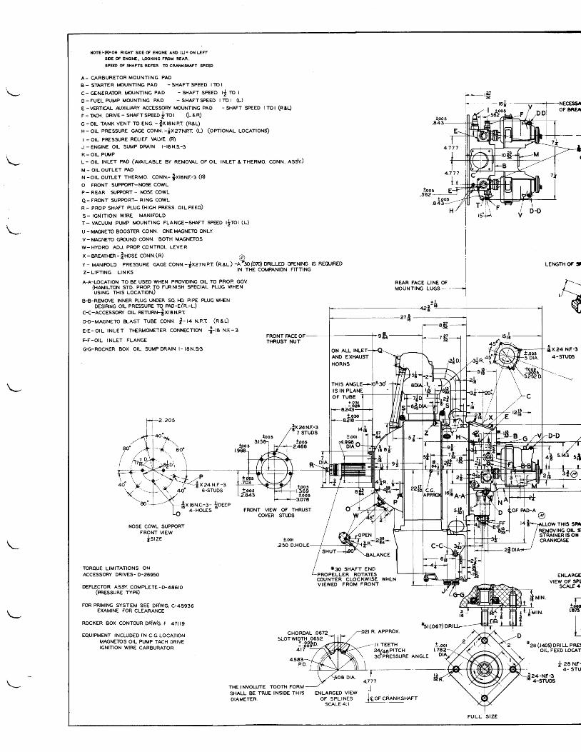
NOTE:-(FFON RIGHT SIDE OF ENONE AND (Q= ON LEF'SIDE OF ENGINET LOOKING FROM FEAR.SPEED OF SHAFTS REFER TO CRANXSHAFT SPEED
A- CARBURETOR MOUNTING PAD
B- STARTER ITOUNTING PAD -SHAFTSPEED ITOI
c- GENERAToR ircuNTtNG pAD - sHAFr seeeo ti ro t
O-FUEL PUMP MOIJNTING PAD - SHAFTSPEED ITO I (L)
E -VERTICAL A,XILIARY ACCESSOFI. MOUNTING PAD - SHAFT SPEED ITOI (ReL)
F-TrcH DRtvE-snerrseeeofrot (L&R)
c -orL rANK vENr ro eNo. - txtaru.er (REL)
H-otL eRESSURE cAGe coruN.-$xzzr'rRr (l) (oprroNAl LocATtoNs)
I _ OIL PRESSURE RELIEF VALVE (R)
J -ENGINE OIL SUMP DRAIN I - I8N.S-3
K - O I L P W P
L- otL TNLET pAD (AVATLABLE By REMovAL oFort - INLETaTHERMo cor . r ru. essV.)
M - OIL OUTLET PAD
N-or l ourLET THERMo. coNru.- |xrerur- r (d
O FRONT SUPPORT-i.IOSE COWL
P- REAR SUPPORT- NOSE COWL
Q-FRONT SUPPORT- RING COWL
R- pRop sHAFT pLUG(HIGH pREss. ot l reeo)
S - I G N I T I O N W I R E M A N I F O L D
T- vAcuuM puMP iiouNTlNG FLANGE-SMFT SPEED trrot(L)
U - MAGIIETO BOOSTER CONN. ONE MAGNETO ONLY
v-I\,IAGNEIO GROTJND CONN. BOTH MAGNETOS
W-HYDRO ADJ. PROP CONTROL LEVER
x-BREATHER-f,rosr conn.(il @)y- MANTFOLC PRESSURE CeCe CONr.r.-$x27N.p.T (A.al) -n7so(o?o) DRILLED oFEN|NG lS REQIJIRED
Z-L;FT;NG LTNKS lN THE COIvPANION FITTING
A-A-LOCATION TO BE USED WHEN PROVIDING OIL TO PROP GOV(HaururoN srD. pRoP To Ft-RNtsH sPEclAL PLUG WHENUSING THIS LOCATIONJ
B-B-REMOVE INNER PLUG UhDER SQ. HD PIPE PLUG WHENDESIRING oIL PRESSURE TO PAD-ETR.-l.)
c-c-AccEssoR/ ou nerunr+-t xtINprD-D-MAGNETo BLAST TUBE coxu. |-t+ H.e.r (nal)
E-E-orL rNLET TI-ERMoMETER coNNEcrroN -t-ra ru.r-sFRONT FACE OFTHRUST NUT
t xeaN. r -a6.STUDS
f x rarvc-:- ljoeee
NECESSIOF BREA
4 7 7 7
4 . 7 7 7
tpol.562 -
!a 4
REAR FACE LINE OFMOUNTING LUGS
+Lf t .a
.-sg
t Z !' 3 2
LE,\GTH Of, '
fix aa xr-r4-5TU6
F-F-OIL INLET FLANGE
GG-ROCKER BOX OIL SUMPDRAIN I - I8N.93
NOSE COWL SUPPORTFRONT UEW
. cstzE
TORQUE LIMITATIONS ONACCESSORY DRIVES- D-2695O
DEFIICTOR ASS/. COMPLETE -}.486I0(rRessune rvpd
FOR PRIMII{G SYSTEM SEE DRWG, C-45936EXAMINE FOR CLEARArcE
RocKER Box coNTouR on'wb r +zttg
EQUIPMENT INCLUDED IN C.G LOCATIONMAGNETOS OIL PUMP TACH DRIVEIGNITION WIRE CARBURATC'R
FRONT VIEW OF THRUSTCO/ER STUDS
t.001.250 D.HO
CHORDAL .0672
*3o SHAFT ENDPROPELLER ROTATESCOUNTER CLOCKWISE WHENVIEWED FROM FRONT
R. APPROX.
+d
J"'zjf on
ENLAR@VIEW OF SPl
SCAE 4 '
M f N . -ll Mrt. r_
-L !oo.jurr.r "it
l lt_
4583P D .
THE INVOLUTE TOOTH FORMSHALL BE TRUE INSIDE THISDIAMETER.
ENLARGED VIEWO F S P L I N E S
SCALE 4: I
SLOTWTDTH.0652l:886to. -
4t7 ----f I I TEETH24146PtTCHso'pRessuee
see (r4os) ont LL pRE:OIL FEED LOCAN
f, za Nr-- 4- STU,lz+-M-s'- 4-STUDS4.777
ill?."-rH,s sr
fnor.rio*^r"^r.
*st(.ooz)
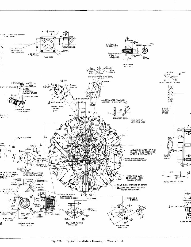
nro.I-rax s -e.oe-sartffif
I ] A D R ' L L JI rq.E' ssuRE ott-. :ED LOCATION raocra) ontu.
c'stNK-eo'4$on*i
tdro22
Dr&
TACH DRIVEFULL SIZE
^ ls': -,.eI ,-.i33 6oi,i,i\6$---_"'-ill".3/r4_+i+*J
/ / l -
- an ' * t oo5! _:- -.aa
61 t
-t:]:-{-=
" : - * - j za
DEVELOPMENT OF JAWcn n.uax$_.azslffi ua.
[.<,-- :r 5t-iNEs ';'ffi'-toot'$$!orl,, vrA_.zrg$L
/ 3oif.9Y!'"*." + fl ' 4 1 / ,1-1/r/- ? /'c I ;l{5 ro FAcE oF GEAR
FRONT,SUPPgRT- RrNG COWL/ /FULLSIZE
5i8-t_
__-t
$ onrul3HOLES
3o'
GEi\ERATOR DRIVEscele I sze
/Qor srARrER
I//
c
OILOUTLET PADFULL SIZE
@S x a s
COWL LUGS WILL BE INLocArroN sHowN wrrxrrc$
ANGULAR LOCATION OF TH]SFLAhIGE TO BE DETERMINEDAT Ei{GINE INSTALLATION,
REQUIRED FOR
EXHAIJST PIPEFLANGEj srze
T2JAWS-EQUALLYSPACED
I,rit
RUE ANGLEOF FLANGEtf- a4-
fixz+r.r.n-s2- STUDS
REi'Or'ING OIL PUMP BODY
MOUNTING LUGSDRILLED HOLES
EQTJALLY SPACED
alf r,lrxc.on. ovER RocKER co/ERs
D€VELOPMENT OF JAW
F -- S : r^CE FOftE|t x: :'r- STRA|NEFIA r € . S : \ g O FEASa
.ozarl.333
l2 TEETH ?O/ag PIICASO.PRESSUEE ANGLE
smi333 ore
llt 6
frur.t* M A X
DRILL
R.6Z
+ooa_ooo
r.500 DrA
o25 R.APPROX
ftf corvl cLEARAT€E DrA. ovERROCKER @VER STIJOS
TNVoLUTE roorH iFORM MUST BETRUE INSIDE THIS DIA.
[;IInttt--?vo*,aa=H
sfrrlj
CARBURETOf
F-F D I A .2 HOLES
r l v rN +r [ iJoos
r.875
VrcUUM PUMP PAD(ruu- sze)
OIL INLET FLANGEFULL SIZE
OIL INLET PADFULL SIZE
;**6o*'r.tooo r
t .625 DrA.
D€t r H
l : ' : : l
I t . t
\J _ .
a l
I
riio.
Fig. 705 - Typical Installation Drawing - Wasp Jr. 83
$ ora.
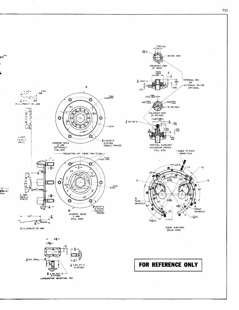
713
!.o02 HEX3t2
.8Put n,
fi- rar.r-r
.3I4 DIA. MAX
HEX
E X T E R N A L S P L I N EOPTIONAL
- lO ' * too5n - - -.2t6
-._^__Cl,-
; - - - i z n
: T . ' - : P \ | s N T O F ' J A W
.osslSP'
+se1.!l!
f-ea Nr-a
2 ) ^ 5i:,- - -Y5,4: : :
-.------ PRO.JECTION OF THESE TWO S
'-$x za ur-s6-STUDSEQUALLY SPACED
t.oos..-- sDtA.
STARTER DRIVEI2 JAW
(oerroNeu)FI.I.L SZE
VERTICAL AUXILIARYACCESSORY DRIVES
FULL SIZE TCABLE TO EACH
\ smnx eluc
RADIO SHIELDING(nena vnw)
FOR REFEREilCE ONIY
3 f - - : :
f . \ f -rtA
7l\,--tr1\! \ l
= \ l= I'/ {i,
#sB /STARTER DRIVE
3 JAW(FULL srzE)
]xea H.r-a1 6-STUDS! EQUALLY
SPACED
)€dI-OPMENT OF JAIY
- 6 t -
-r$-
l*Htr,.Hr+t l vf r x 2 4 N F - 3
: x ]07
i
- e d -
SFRONTMANIFOLD
t ore ontu-
CARBURETOR I/PI}.ITING PAO
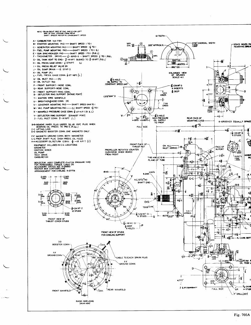
torg,-(Rl,or.| $Gxt llDE OF Er{G. AfiO (L}'Ofi LEFTSID€ OF EilG, LOOXIi'G FFOI' REARSHAFT SPEEDS REFIR ?O CRANK3HAFT SP€ED
A- CARS.IRETOR NA-YgH
B- STARTER iDul{Tlt\G PAD-SMFT SPEED I TOI
c- cEr€RAToR rrouNTtNG pAD-g{AFr'speeo tl ro r
D_ nf,L pur/p rbUNTttC pAD_SHAFT SpEED trO r (r_)
E: cUN Syr{cHRONtZER pAD-grAFT SPEED tTOt (Ra.L)
F- TAcl-torrETER DRIvE- j-rexs-r - sHAFr seeeo j To | (RlL
G- orL TANK lol? ro exc- !-u-Ner zusHED ro t-ta-Ner (nal)
H- o|L [email protected] i-27N.PT (L)
I - OIL PRESS. RELIEF \ALVE (R}
J- OIL SIJMP ORAIN_h' I?NF.3
K- o|L PUMP (R)
L- FLEL pREss. cAGE coNN. i-az ner (r- )
N_ oL f{-ET BAD_(R)O- OIL OUTLET BAD
P - FRONT SUPPORT- NOSE @WL
O- REAR SUPPORT-ISSE COWL
R- FrcNT SUPPORT-RING COWLs- o€FLEcroR RtNc supPoRr lrNrerc ponrl
T- GNITON WIRE MANIFOLD
u: BReATHERllpsEcoNN. lRl
V- @VER},IOR I,|OI'NTIiIG PAD-SHAFT SPEED U44TO I
w_ vAc. puMp lvouN?p.lc pAD_(L) srlrr speeo r* ro r
x - MANtFoLo pREsstJRE cece conn. {-zz-N.er (R. r. D
y- DEFLESIoR Rtlrc SUPR RT (ExHAJsr pcrtT)
z- FUEL rNLEr coNN. i- ta-Net /r )
B8-RE[,|O/E lNf€R PLTJG UND€R SA. FO. PIPE PLUG wl-€ND€SIRIhIG OIT. PREsS. TO FAD E.R.U-)
C.C LFTING LINKD-O MAGNETO BOOS.1€R CONN. ONE MAGNETO ONLY
F-F I|AGI.|ETO GROUND CONN. rcTH [,l,AG1'lETOs
G,€ PROP. SI{AFT R-IJG GIIGI-I PRESS. OIL FEED)H-H{CCESSORYO|LRETURT.T COr.rN. f
-ra Uer (u)
EQUIPI,ENT INCLUDED lN C.G LOCATIONSMAGT€TO5TGNITION WIRESOIL PUMPTACFI. DRIVE€TRBURETOR
D€FfJcToR AssY co[rPlJTE->41726 en€ssun€ wPq)FOR PERMISSB.E TORQ{JE LOADS ONACCESSORY DRIVES SEE D'26950R/OCKER BOX COTITOJRSAI|DARMNGEMENT FOR COII/LITIG R.27TI8
r3.53r
tooSt-
3.531lpos
2565Foc[t' - t
2.5651.loos
I
fx2a NF-312 STLDS
FRONT VIEW OFTNUST CO/ER STI.DS
t375'toor o
FROIIT VEIVOF STuDSFOR CC'IA'LING SLPPOR'T
I !0roLrErrs
fh" O }|oLEIGH PRESS{JREOIL SUPPLYTO PROP
ON ALLINLET }ORNS
REAR FACEOFtOLr{TNG
r--_4.777'
I
. i Gorcot*s.. tt
EI{-ARGEO VEWOF SPI-INESSCALE.4:l
fixze}f-s4 TNSERTS
fi aee
SPACE REODEREIn/IIG FA
st---------i
G-GROOVES EOUALLY SPrc!
fl x2aNF-34 STUDS 1
OFa
IN.PORT
z{o'
CARB DN
-42{fA-
?-
FRO.IT FrcE OFTHRUST T{JT
TI-IIS A'{GLE S N
Pl-AtE OF TUBE
€€x3ra0
\Y)t-L_':I{r'7 r 3 4-/
-Tv loos-/ L.*r'o
:386,
i---.--- -cL't,-E
--r-t 7 'r E
. lt5 lT r l u_ I--1i-err
&sTr.at
zsoa!.o,\
- | x a+ r.rr- a---16 sruDs r e
f x r O N C - 3 - = r
ffitrr- t
F.F
GROUND
. tI t 6
RADIO SHIELDIiIG(nern vrew,)
REAR MANIFOLD
Fig. 7054
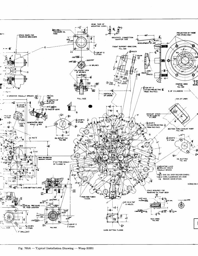
PRO,'ECTPN OF T}EEottY
ffifi.'i'tr-3[sr *\H ,4
hlu4--t
i r
;SPACE REa,D. FoR
/
**,* *f^(ERs
/
J , -I- E-�--rS'
{ rac n r - r4 STT.DS
;i-s JAwsJEpUALLY
SPACED
1@ !.oro" .52o 4 SARTER DRilE3-J.il
Fllr lrzE
6 ! nElru
- {tr--
6-GROOVES EQUALLY SPACID
l---.i-F-venncer_ e\
I **,*/\..
t oF cYLrNo€R, \',
.OF UT€R
firaar,rF-3 --2-STUOS
.ao"tt , n
)$
i | re l xr-s9 STr.rOS PRO-ECThIG SFROM PADFACE.
.?@'DtA.r8trtdLEiIGTH OFE spt rNr
i . Lax.
.675::tglor^TO FACEOFGEAR
FULL SIZE
o- l
t,-.-.
ry"NOR DRIVEsc r/E i srzE
CARB FTTOT' NA}€E
.r+l83lneer.a PnE ssrJREOIL FEED I-oC,�TPN
.soo'.*9!
f,xea}f-r2-STiDS
r"nSECTPN THRU EXHAUST PORT
FULL SIZE
3 r 'r?t'\
-t -�-rl-o"- Sn
OL I}TLETPAD�T,LL 3ZE
9I\DUNTII{G LUGS$'oeruuo xouesEQIALLY SPACED
EI.IG. DIA c^/ER ROCKERCCI\/ERS,
i, D-CO/VL CLEARAI.IC E DlA, c^/ERtft ROCKER CO/ER STUDS.
- * 2 f e
n(nss) ue. r
+-_-+r,
a f1
ROO Tt8E5ro.DrA.
SPACE REqJIRED FORREIYOVING OIL PUMP BODY.*
t -o2 -
8 tii
@:*
ILARGED VIEWoF sPt-h€s
-----t4il . --rl_r x24NF-3I 4 STUDS IT l x24 i l r '
I 4 sruDs
@/ L3252 0
/ +oo2,/ _,OOO5
i ior
" i-tiilllt l I , i l' l t z i l IL i I l l, u l t 6
-scE lfrf,al'fiac
i l "ir
hr
OI.(I,TfT PADnltrll
"FT- q i
I
Fig. 705^{ - Typical Installation Drawing - Wasp S3H1
CARB. BOTTOM FLAI€E
TACH. F r,ERI-L J:ZE
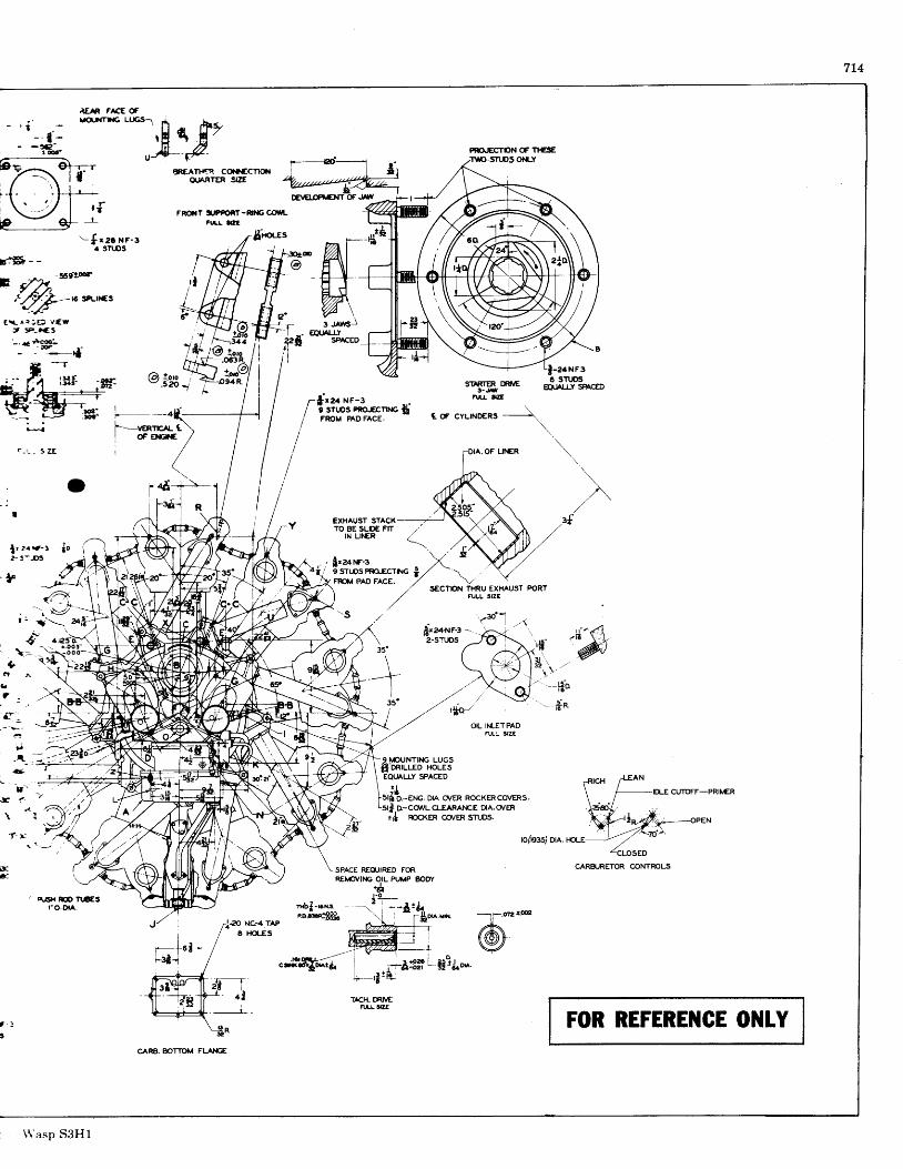
7L4
iEN F^CE OF
'-{'g1r-r
F:*$ - -
$Clgct! -r-)1-,?T6srurcs
OUANTER gZE
FRO{T i'P]FOflT-FT€@TLru,! t(!E
$-rr:tes
$n
sTr.Ds oil-Y
SURTER DFIE3-Jfl
Flrr |IZE
f a ^ . ; E ) Y f Wt 3P-trES
- '+ tS
._T
| ter xr-r9 STIJOS FRO..ECT|NG TFRC'M PADFACE.
.il-lsi
ti l
EXHAUST STACXTO BE SLDE FTT
IN LII€R
FMt| PAD FACE.
c. f CYLTND€RS --------\
firaa{F-3 --,*1 .4
2-STTJOS
OIL IIILET PADF1JLL 3ZI
X
{."L. - r t Z - - -
f : q"-- alfr
,-{lrzarc-39 STI,DS PRO.ECTING i
35'
---r1
gs'
SPACE REOUIRED FORRElvOl/ll{G OIL PUMP SODY
;.1€o nc-e.ree e+a'
M JZ'"'",'"/
Er-rcLEs W,, --,- T*-
"-lflS!'"^{ l r-&#llgtg'^.;t |
*-'3!L-r- al rAcH. m €
I _ Rrl-g|zE
:*nbJ-ro.11^ -..2--l-grg.raiec$$"
^\,, -1
9o^.r'*
SECTPN TI{RU €XHAUST PORTFULL SIZE
9]'DUNT|I{G LUGSfi'oRtueo nouesEQTALLY SPACED
DLE CUTOFF-PRIi/ERD.-ET.IG, D|A Or'ER ROCKERCC^/ERS.D-CO/VL CLEARArcE DIA, O/ER
;* RocKER co/ER sruDs.Z\\/r------€PEN
7o',.rc(nesJ on. rou
CARzuRETOR @NTROLS
!R.ET D TL€ESro.or^.
@:
t - l
I
FOR REFEREilCE Ol{tY
WF 3
f r2er f - r lo f
n-^Ai,
\ \ 'asp S3H1
GARB. BOTTOM FLAIGE
7t5RUN.IN OF ENGINES AFTER OVEREAUL
t2. Connect fuel pump drain line.
13. Connect a tee into the blower rim manifoldpressiure line and lead to the economizerunit of the NA-Y9J carburetor (used onsome Wasp engines).
L4. Connect a mercury manometer to NA-Y9C,NA-Y9G or NA-Y9G1 carburetors to indi-cate the absolute pressure below the car-buretor when the automatic mixture andpower control unit is checked in "Mid" and('Cruising" position. This connection ismade at the carburetor on the acceleratingpump side near the parting section andautomatic mixture regulator flange.
15. Connect a line from the automatic mixtureand power control unit of NA-Y9C, NA-YgG or NA-Y9G1 carburetors to a tee inthe main oil pressure line.
16. Connect a line to the oil drain connectionof the automatic unit of NA-Y9C, NA-YgG or NA-Y9G1 carburetors and leadthis to the oil drain pipe on the left side ofthe engine rear section.
17. Connect breather lines to the breatherconnections of the engine.
18. Connect priming system.
19. Connect fuel pressure gage line to car-buretor.
20. Connect magneto ground wires.
2L.* Connect head thermocouples to at least twocylinders.
22. Install carburetor air inlet duct.
23. Connect air inlet thermometer line in airduct to carburetor.
24. Connect oil inlet and outlet lines.
25. Install exhaust stacks.
26. Install cooling cowl (if used).
*Note-A survey of all cylinder hgad andbanel tdmperatures should be madeon the first engine run in a new testhouse, or on the first engine of eachtype to be run in an old test house.Tliese temperatures should be deter-mined by spark plug gasket thermo-couples ior- head temperatures -andrivet type thermocouples embeddedjust ab6ve the cylindef barrel mount-ing flange for banel temperatures.Frbm tliis temperature survey, thetwo hottest cylinder locations can bedetermined ahd thermocouples usedat these locations for all future tests.Cylinder barrel temperatwe measure-ment is unnecessary after the initialcheck.
The installation diagram, Fig. 705, *.itt behelpful in finding the previously mentionedconnections.
The test propeller should be inspected prior toinstallatiott'ott'the engine propell-er shaft to besure that its hub splines and nut are free fromburrs or dirt which might cause damage to- theengine propeller shaff. The propeller shaftsnSUa b^e c6vered with a light o-il, the propellerinstalled and the attaching nut securely tight-ened. Any looseness will allow the test club towork on the propeller shaft which may causedamage or galling. For the tightening gperat-iona torlue of from 625 ft.-lbs. to 750 ft.-lbs.should be applied to the propelle,r nut. Thitmay be accorirplished bv urling a bar fogl feetlon! and applying a weight of-between 160 and190-pound; ai the end ol the bar. The weightshould be applied at right angles to the ground.The bar shorild not be struck with a hammer orother heavy instrument except to check the tlght-ness of thd nut. To check-the tightness of thenut after the above operation has been per-formed, a 21h lb. hammel may be used to strikethe bar near the nut. Care should be taken notto exceed a normal swing of the hammer.
TEST PROCEDUREGENERAL
An experienced test operator should havecharge of the run-in of an overhauled engine.The operator should keep the engine and instru-ments under constant observation. A log of theengine test (see sample sheet, FiS. 706) recordingobservations at 15 minute intervals, should bekept filed with the engine inspection and overhaulrecords at the completion of the test.
It is recommended that the temperature of theair entering the carburetor be maintained at90" F. (32" C.) for test stand operation. This isparticularly important when running-in enginesequipped with NA-Y9C, NA-Y9G or NA-YgGl carburetors.
The engine should be watched for oil and fuelleaks, and= necessary corrections should be madeduring the run-in, where possible. A few minoradjuslments, 6uch as oil and fuel pressure reliefadjustments, are usually necessary-and should bemade during th€ run-in.
Where the engine is equipped with short ex-haust stacks and it is possible to watch the ex-haust flame from each cylinder, the flames shouldbe watched for any difference or change in colorwhich might indicate misfiring plugs, excessivelylean or rich mixtures or other discrepancies at oneor more cylinders.
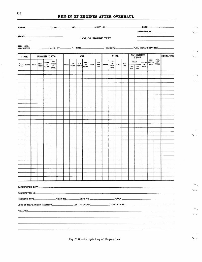
7L6RUN.IN OF ENGINES AFTER OVERHAUL
ENGINE SERIES-NO.-SHEET NO'
sTD. OBS.BAROMETER-IN. HG. AT- F. TIME HUMIDITY-FUEL (OCTANE RATING)-
OBSERVED BY
LOG OF ENGINE TEST
CARBURETOR DATA
CARBURETOR
MAGNETO TYPE
LOSS OF REV'S.-RIGHT MAGNETO
RIGHT NO,-LEFT NO.
LEFT MAGNETO TEST CLUB
REMARKS
Fig. 706 - Sample Log of Engine Test
7t7RUN.IN OF ENGINES AFTER OVERHAUL
STARTING
Before starting the engine, a wobble pump inthe oil system should be operated until the enginepump is supplied with oil. This precaution isparticularly important in cold weather. Whereit is extremely cold, the oil feed line should bedisconnected at the engine oil pump and the coldoil forced out of the line through use of the wob-ble pump just prior to starting the engine. In-structions for starting the engine are containedin the Operators Handbook.
These instructions should be strictly adheredto.
Oll Pressure - If the oil pressure, after starting,does not register on the gage almost immediatelythe engine should be stopped and an investiga-tion made for the cause.
Before the run-in is completed, the pressureshould be set, by adjusting the relief valve sothat it is 70 - 90 lhs./sq. in. (5 - 6 kg./sq. cm.)with the engine turning 2200 R.P.M. and the oilinlet temperature at 140" - 167' F. (60'7 5 ' C . ) .
Fuel Pressure - If the fuel pressure is notwithin the desired range of 3 - 5 lbs./sq. in.(0.21 -0.35 kg./sq. cm.) at 1000 R.P.M. andabove, it should be adjusted by means of the fuelpressure relief valve.
Englne Run-In Schedule - The followingschedule outlines the minimum run-in periodrecommended for properly seating piston ringsand burnishing newly installed bushings, etc.,in an overhauled engine.
THE ENGINE
tenths inches of mercury), below the carburetorin the "Mid" and "Cruising" positions with thethrottle wide open. If the unit will not main-tain the desired regulated pressures within theaforementioned limits, it is not functioningproperly. If the unit has been overhauled andbench tested as described in Chapter XVII, onlyin rare cases will it require readjustment and thisshould be done only by someone who is familiarwith the proper procedure.
To check the automatic mixture control unitwhile installed on the engine, the following pro-cedure should be carried out:
1. With the throttle partly closed, (1200R.P.M.) put the selector valve in thet(Mid" position and speed up the engineby opening the throttle until the mano-meter indicating pressure below the car-buretor reaches a point where there is nochange in pressure for an increase inthrottle opening. This will be the pres-sure to which the automatic unit is regu-lating and it should remain constant for allthrottle positions from this point to fullthrottle. If the operation is satisfactoryand the pressure is correct for the particu-lar carburetor setting, the "Cruising"
position should be checked.
2. To checkl the "Cruising" position, partlyclose the throttle and move the selectorvalve to the "Cruising" position; thenspeed up the engine by opening the throt-tle, as was done in checking the "Mid"
position. The manometer indicating pres-sure below the carburetor should show anincrease in pressure until it indicates theregulating pressure for the "Cruising"
position, anil should remain constant forah throttle positions from this point tofull throttle.
Note-The pressure below the carburetor,when in "Mid" or "Cruising" positionis controlled by the air shutters;therefore a thorough investigation ofthe shutters and their linkage should bemade before readjusting the regulatorunit.
3. The throttle should be partly closed, untilit is positively controlling the engine speedand power, before moving the selectorvalve out of the "Cruising" position andinto the "Mid" position. The throttleshould be still further closed, until it isagain controlling the engine speed andpower before moving the selector valveout of the "Mid" position and into the"Manual Full Rich" position or "Emer-gency" position. The engine should be
R.P.M.800-1000
L200140016001800190020002L00
Rated Speed
Minutes15
t2060606060603015
Checklng Operatlon of Carburetors havlngPratt & Whltney Autornatlc Mlxture andPower Control Untt - This unit should beoverhauled and bench tested as described inChapter XVII. After the overhauled enginehas been run-in, it is advisable to check theoperation of the unit when mounted on thecarburetor and controlling its operation. It isalso desirable to check approximate fuel consump-tion in the two automatic positions. Theprincipal check of the unit is for its ability tomaintain constant, without hunting, the desiredabsolute pressure, plus or minus .2 in. Hg (two-
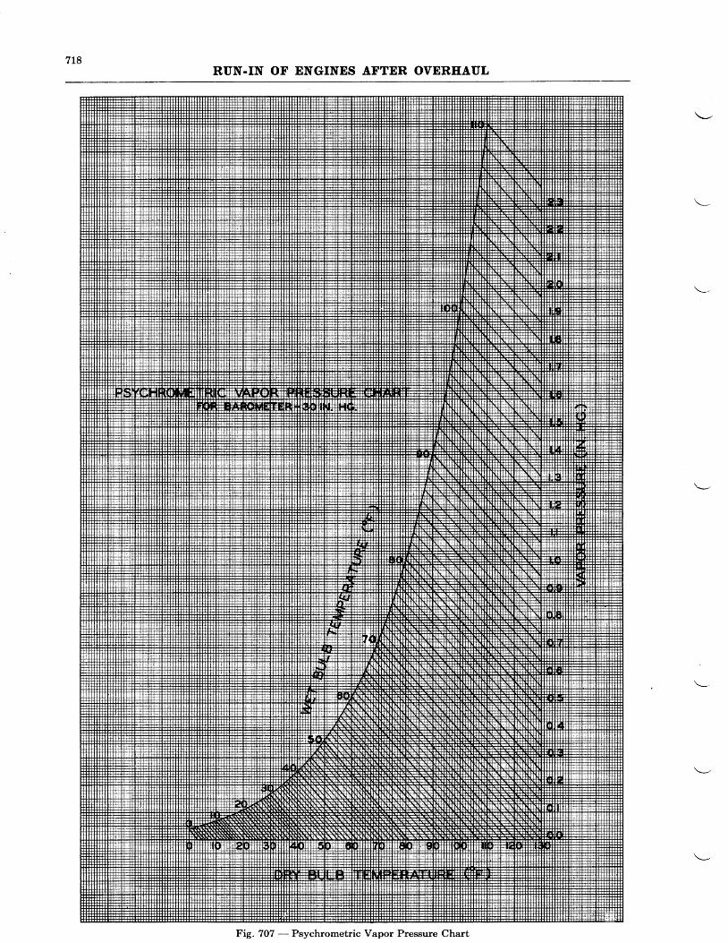
7L8RUN.IN OF ENGINES AFTER OVERHAUL
Fig. 707 - Psychrometric Vapor Pressure Chart
7L9RUN-IN OF ENGINES AFTER OVEREAUL
operated in the "Manual Full Rich" posi-tion at all times on the test stand exceptwhen checking the operation of the Auto-matic Mixture and Power Control Unitand for fuel consumption checks.
EORSEPOWER
A reasonably accurate determination of thehorsepower dei'eloped by a Wasp Jr., Wasp orHornet engine may be made by ieferring to thesea level calibration curve for the particularengine (assuming that the test stand is locatedapproximately at sea level). The OperatorsHandbook describes, in detail, how to use thecalibration or operating curves, including in-formation pertaining to the carburetor air tem,perature correction.
If the test stand is situated appreciably abovesea level, the altitude part of the calibrationcurve should be used as described in the Opera-tors Handbook.
The information which follows is furnished inthe event that, for some reason, the closest possi-ble determination of actual horsepower on thetest stand is desired.
Absolute Blower Rtrn Pressure or absolutemanifold pressure (in. of Hg) is the algebraicsum of Observed Blower Rim Pressure and Cor-rected Barometric Pressure. Thus if an engineis operating with a Blower Rim Pressure of -2.3in. Hg and Corrected Barometer is found to be29.22 in. Hg then the Absolute Blower RimPressure (absolute manifold pressure) is 29.22 *(-2.3) : 26.92 in. Hg.
Corrected Barometer is found by subtractingfrom the True Barometer the vapor pressure(i.e. pressure due to moisture content) in the air.For example: assume wet and dry bulb tempera-tures of 78' F. and 84' F. resp,ectively Q8/84.From the Psychrometric Vapor Pressure Chart acorrection factor of 0.9 is found for these tem-peratures. Thus, if the True Barometer is 30.L2,the Corrected Barometer is 30.12 - 0.9 : 29.22in. Hg.
Trre Barorneter is computed from the Ob-served Barometer by correcting the latter fortemperature variation away from the standardtemperature upon which the barometer scale isbased. Thus if the Observed Barometer is
The carburetor is of the fixed jet type, theproper jet sizes having been determined andtested in each carburetor. Under no circum-stances should these be changed without firstconsulting the factory.
DETERMINATION
30.25 in. Hg at 79" F., refer to the BarometricTemperature Correction Chart, supplied with thebarometer by the manufacturer, and for 30.0 in.Hg and 78"'F. find a correction factor of -.13.The True Barometer is found by adding the cor-rection factor (with the conect sign) thus:
30.25- .13nn True Barometer
The True Barometer should be computed andrecorded once every hour.
Wet and. Dry Bulb Temperatures are requiredin order to compute the vapor pressure from thePsychrometric Vapor Pressure Chart (Fig. 707)and obtain the Corrected Barometer. Readingsshould be recorded once every hour.
After the absolute manifold pressure has beenderived and used with the engine R.P.M. to readhors,epower on the calibration curve, the horse-power read from the curve must be conected forthe variation from 60' F. (standard temperatureat sea level). The following formula can thenbe used to deterrhine the actual horsepower:
Actual Horsepow€r:Horsepower Read on Curve
For example, consider the Wasp engine runningat 2200 R.P.M. with an absolute blower rim pres-sure of 32.5 in. Hg and a carburetor air tempera-ture of 80" F. At 32.5 in. Hg and 2200 R.P.M.,the sea level calibration curve shows 525 brakehorsepower.
Using the horsepower correction factor tablewhich follows, a correction factor of 1.019 isfound for the carburetor air temperature of 80' F.Using the correction factor in the above formulafor actual horsepower, 525 : 515 actual horse-power. 1.019
The following table of correction factors forcarburetor air temperatures should be used withthe foregoing formula.
720RUN.IN OF ENGINES AFTER OVEREAUL
AirTemp. oF.
CorrectlonFactor
Correct lonFactor
AirTemp. oF.
CorrectlonFactor
H. P. CORRECTION FACTORSBarometer 29.02 ln. Mercury
AirTemp. oF.
8 1 . .
95. .1 .0339 6 . . . . 1 . 0 3 49 7 . . . . L . 0 3 598. . . .1.0369 9 . . . . 1 . 0 3 7
100. . . 1.038101. . . .1 .039L 0 2 . . . : . . . . . 1 . 0 4 0103 . . . . 1 .041104. . . .L.0421 0 5 . . . . L . 0 4 3106. . . .1.044t 0 7 . . . . L . 0 4 5108. . . .1.046109. . . .L.047110. . . .L .047111. .1 .048Ltz. . . .1.049113. . .1 .050Lt4. . 1.051
or 434lbs./hr. In case of stands equipped with afuel flowmeter the flow in tbs. /hr. is read direct.
Speclffc Fuel Consunptlon (lbs-/8.P./!t.)j Stto,rtd it be desired to-determine Specific FuelConsumption (not considered practical in averagecase on held test stahds) the actual horsepower,arrived at as described under "Horsepower
Determination", must be used. The followingformula may then be emploYed:
S.F.C, Fuel Flow (lbs.ihr.), : m
Thus for an ensine developine 525 H.P. with afuel flow of 350-lbs.1hr., the Specific Fuel Con-sumption is equal to:
Cheeklng FueI Flow - After the engine hasbeen run--in, the gross fuel consumption inpounds or gallons per hour should be checked.it is recomirended ihat the fuel consumption bemeasured at several points within the cruisingrange and at rated power and speed of the engine.
The gross fuel consumption may be determinedreadily at all times if a fuel flow meter accuratelycalibrlted for the specific gravity of the fuel isinstalled in the fuel line tb the engine. Flowmeters of this type should be calibrated onceevery two months and should be accurate towithin L/6 tlvoughout its usable range. It-ryuyalso be found bf timing a given weight- of fuelthat the engine- consumes from a weigb! t-ankmourrted on a scale. A third method of findingthe gross fuel consumption is by timing^a -givenvolume of fuel consumed. The volume fuel flowtank should be accurately calibrated for thespecific gravity of fuel. See Tig. 794,for thevarious arrangements for determining fuel flow.
When determining gross fuel consumption !Vthe volume or weifhl method, the longe,r theduration of the check, the more accurate the re-sult will be. However, in any case, the timeinterval should not be less than one minute(60 seconds).
Fuel Flow-Fuel flow (lbs./hr.) is computedby means of the formula:
Flow _lbs. x 3600sec.
Thus if it takes74.5 seconds to empty 9 lbs. of gasout of the weight tank, the Fuel Flow : 9_. J600
74.5
350- :525
Note-Becalrse
.666 lbs. lH,.P.llv.
of the several engine modelsand numerous carburetor settings in-volved, it is not feasible to cover actualfuel consumption figures in this manual.Where fuef consumPtion figures aredesired for a particular englr-le modeland carburetor setting, informationwill be furnished by the-Pratt & Whit-ney Aircraft Service Department uponrequest.
Checklng Otl Consumptlon - qg+ng. .th"run-in, th6 goss oil consumption should be deter-mined' while the engine is
-running the hour at
2000 R.P.M. The consumption may b-e ascer-tained by subtracting the weight of oil- at theettd of tlie hour, as in-dicated on the weight tank
72LRUN-IN OF ENGINES AFTER OVERHAUL
scales, from the weight at the beginning of thehour. Readings should be recorded every 15minutes.
If the gross oil consumption is not more than4.5 lbs. for Wasp Jr.,6lbs. for Wasp, or 7.25 lbs.for Hornet engines, and not increasing during thelast two 15 minute intervals, the condition ofthe newly fitted piston rings should be consideredsatisfactory. If the oil consumption is high, orincreasing during the last two 15 minute inter-vals, the run-in may be continued for an addi-tional two hours at 1600 R.P.M. to further seatthe piston rings, after the run at rated speed iscompleted. If the condition is not correctedafter this run, as determined by a check run ofone half hour at 2000 R.P.M., the cylindersshould be removed and the condition of the ringsinvestigated.
Flnal Englne Check - Since the test clubpropeller does not have the same flywheel effect
as an airplane propeller, it is impractical tomake a final idle adjustment of the carburetoron the test stand. However, at the completionof the run-in, the engine should be checked foridling, acceleration, and operation of the mag-netos.
The engine should not lose over 100 R.P.M.when opeiating on one magneto at 907o ratedspeed. Checks on single magnetos should bemade in as short a time as practicable, as con-tinued running on one magneto at high horse-power output can cause serious detonation.After checking one magneto, the engine should beallowed to run 5 or 10 seconds on both magnetosbefore switching to the other alone.
If the engine is to be placed in storage, itshould be run at least 30 minutes at 50% normalrated speed on unleaded gasoline, before beingremoved from the run-in stand.
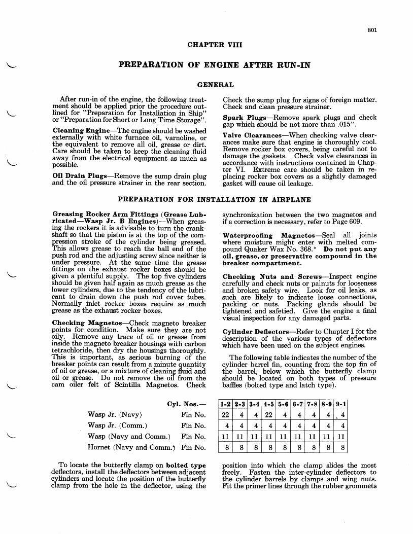
801
CHAPTER VIII
PREPARATION OF ENGINE AFTER RUN-IN
GENERAL
After run-in of the engine, the following treat-ment should be applied prior the procedure out-Iined for "Preparation for Installation in Ship"or "Preparation for Short or Long Time Storage".
Cleanlng Englne-The engine should be washedexternally with white furnace oil, varnoline, orthe eqoivalent to remove all oil, grease or dirt.Care should be taken to keep the-cleaning fluidaway from the electrical equipment as much aspossible.
Oll Dratr!_ Plugs-Remove the sump drain plugand the oil pressure strainer in the iear section.
Greaslng Rocker Arm Ftttlngs (Grease Lub-rlcated-Wasp Jr. B Englnes)-When greas-ing the rockers it is advisable to turn the crank-shaft so that the piston is at the top of the com-pqessio4 stroke of the cylinder being greased.This allows grease to reach the ball end of thepush rod and the adjusting screw since neither isunder pressure. At the same time the greasefittings on the exhaust rocker boxes shodd begiveq a_ plentiful supply. The top five cylindersshould be given half again as much grease as thelower cylinders, due to the tendency of the lubri-cant to drain down the push rod cover tubes.Normally inlet rocker boxes require as muchgrease as the exhaust rocker boxes.
Checktqg Magnetos-Check magneto breakerpoints for condition. Make sure they are notoily. Remove any trace of oil or grbase frominside the magneto breaker housings with carbontetrachlolide, then dry the housings thoroughly.This is important, as serious burning of thebreaker points can result from a minute quantityof oil or grease, or a mixture of cleaning fl:uid aniloil or grease. Do not remove the oil from thecam oiler felt of Scintilla Magnetos. Check
Wasp Jr. (Navy)
Wasp Jr. (Comm.)
Wasp (Navy and Comm.)
Check the sump plug for signs of foreign matter.Check and clean pre$sure strainer.
Spark Plugs-Remove spark plugs and checkgap which should be not more than .0L5".
Valve Clearances-When checking valve clear-ances make sure that engine is thoroughly cool.Remove rocker box covers, being careful not todamage the gaskets. Check valve clearances inaccordance with instructions contained in Chap-ter VI. Extreme care should be taken in re-placing rocker box covers as a slightly damagedgasket will cause oil leakage.
synchronization between the two magnetos andif a correction is necessary, refer to Page 609.
Waterprooffng Magnetos-Seal all jointswhere moisture might enter with melted com-pound Quaker Wax No. 368. * Do not put anyoil, grease, or preservatlve cornpound. ln thebreaker cornpartment.
Checking Nuts and Screws-Inspect enginecarefully and check nuts or palnuts for loosenessand broken safety wire. Look for oil leaks, assuch are likely to indicate loose connections,packing or nuts. Packing glands should betightened and safetied. Give the engine a finalvisual inspection for any damaged parts.
Cyltnder Deflectors-Refer to Chapter I for thedescription of the various types of deflectorswhich have been used on the subject engines.
The following table indicates the number of thecylinder barrel-fin, counting from the top fin ofthe barrel, below which the butterfly clampshould be located on both types of pressurebaffies (bolted type and latch type).
position into which the clamp slides the mostfreely. Fasten the inter-cylinder deflectors tothe cylinder barrels by clamps and wing nuts.Fit the primer lines through the rubber grommets
PREPARATION FOR INSTALLATION IN AIRPLANE
Cyl. Nos.-
Fin No.
Fin No.
Fin No.
Hornet (Navy and Comm.) Fin No.
To locate the butterfly clamp on bolted typede,flectors, install the deflectors between adjacentcylinders and locate the position of the butterflyclamp from the hole in the deflector, using the
l-2 2-B 8-4 4-6 5-6 6-7 7-8 8-9 9 - l
22 4 4 22 4 4 4 4 4
4 4 4 4 4 4 4 4 4
1 1 1 1 1 1 11 1 1 1 1 1 1 11 1 1
8 8 8 8 8 8 8 8 8
802PREPARATION OF ENGINE AFTER RUN.IN
in the deflectors and connect to the cylinderswhere necessary. The primer lines should befastened to the intake pipes with clamps.
For Wasp Jr. engines which incorporate a valvelubricator system and require installation of thecylinder oil feed pipe on No. 1 cylinder, fit thelrpper section of the oil feed pipe through the rub-ber grommet in No. 1 cylinder heail deflectorand connect it to the inter-ear pipe on the cylin-
General-Unless an overhauled engine is to beplaced in service within a few days after run-in,it should receive special treatment before beingplaced in storage. Previously, "Long or ShortTime Storage Treatment" was applied to theengine, depending upon the length of time andclimate conditions to which the engine would besubjected. However, since the final destinationof an engine is unpredictable, it is recommendedthat all engines be given the maximum amountof storage protection. It is recommended, there-fore, that the following treatment which is com-parable to the previously recommended "LongTime Storage" be applied to all engines whichare not to be used immediately after overhaul.A tag indicating the date of treatment should beattached to both the engine and the packingcase. Engines to be shipped overseas should bepacked in a special double thickness waterproofedpacking case.
Prellmlnery Treatment-During the last 30minutes of operation previous to storage, theengine should be run on clear or unleaded gaso-line. The engine should then be washed downwith white furnace oil or varnoline, or theirequivalent, to remove all grease and dust. Whenwashing the engine, the cleaning spray should bekept away from all electrical equipment. Pref-erably while the engine is still warm, drain theengine of excess oil by removing the sump drainplugs and main oil screen and plugs. Clean andreplace the screen and all plugs.
Within two hours after the conclusion of theclear gasoline mn, spray corrosion preventivecompound, Rust Veto No. 3568-8*, into eachcylinder, with the piston at the bottom of itsstroke, in sufficient quantity to insure adequatecoverage..
The following procedure should be completedas soon as possible after engine shutdown, butin every case the requirements regarding RockerBoxes and Exhaust Ports should be completedwithin 24 hours.
Roeker Bor Covers-Remove and clean therocker box covers.
Rocker Boxes-Inject sufficient corrosion pre-ventive compound, No-Oxide EEE, * into the
der with a hose connection. The hose connectionshould be secured to the pipe with wrap locks orclamps. The lower end of the pipe should thenbe connected to the lubricator pump.
The latch-type deflectors are installed in thes€rme manner as the bolted-type with the excep-tion that the inter-cylinder deflectors are latchedto the adjacent cylinder head deflectors insteadof being bolted.
PREPARATION OF ENGINES TOR STORAG}E
rocker boxes. to coat thoroughly the valverockers, valves, valve springs, and the interiorof the rocker boxes. Actuate the valvemechanism to insure thorough coating of thevalves and valve gurdes. Replace the rockerbox covers.
Thrust Bearlng-Remove the thrust bearingcover plate, and thoroughly coat the thrust bear-ing with corrosion preventive compound, No-Oxide EEE *, then replace the thrust bearingcover plate.
Generator and Vacuunr Punrp Drives-Re-move the generator drive and vacuum pumpdrive cover plates and apply corrosion preventivecompound, No-Oxide EEE *, to the splines andbearings. Replace the cover plates.
Exhaust Ports-Spray a sufficient quantity ofcorrosion preventive
"compound, Rust Veto No.
3568-8*, into the exhaust ports to coatthoroughly the heads of the exhaust valves.The exhaust valves should be in the full openposition to insure a thorough coating. Installthe exhaust port covers.
Internal Englne Preservatlon-(To be com-pleted prior to cylinder treatment). With sparkplugs removed, pump corrosion preventive com-pound, No-Oxide EEE *, through the engine oilpassages by means of the engine oil pump insufficient quantity to^411. the system. Thit.willrequire some mearu of driving the propeller shaftat a speed of approximately 150-200 R.P.M.Do not allow the first oil leaving the engine oiloutlet to mix with the supply which is enteringthe engine. Rotate and rock the engine on thestand to coat thoroughly the interior. Drain theexcess compound from the sumps. Replace theplugs and safety in place,
Cyllnder Treatment-Turn the engine standso the engine propeller shaft is extending ver-tically upward. Close the lower set of sparkplug holes with plugs. With the intake valveopen and the piston at the bottom of the stroke,spray the interior of each cylinder with corrosionpreventive compound, Rust Veto No. 3568-8*,through the top set of spark plug holes, so that aquantity of spray will be deposited on the intakevalves as well as on the cylinder walls. Follow-
803PREPARATION OF ENGINE AFTER RUN.IN
ing this operation, rotate the crankshaft at leastsix revolutions for piston ring coverage. Re-spray each cylinder with the piston at the bottomof the stroke for final cylinder wall coverage.Remove the plugs and drain the excess compoundfrom each cylinder by tilting and rotating theengine on the stand. After draining, installdehydrator dummy spark plugs, Protek-Plugs*,in all the spark plug openings. Attach the sparkplug leads to the dehydrator plugs, and insurethat the plugs are tightly seated on the sparkplug bushings. Do not turn the crankshaftafter thls operatlon.
Note-Do not remove the moisture seals fromthe dehydrator plugs, until they areto be installed.
Palnted Surfaces and Rubber Parts-Corro-sion preventive compound, Rust Veto No. 3568-B *, fu detrimental to paint and enamel. Removeany of this compound spilled or sprayed ontopaint€d surfaces by wiping with a clean, drycloth.External Englne Cleanlng-Spray the ex-terior of the engine with cleaning fluid (whitefurnace oil, or varnoline) and dry with com-pressed air. When spraying the engine, thecleaning spray should be kept away from allelectrical equipment. Particular attention mustbe given to removing cleaning fluid from allrubber parts.
Carburetor Openlng-Install the hot spot, ifshipped with the engine. Securely attach a %pound bag of dehydrating agent, Silica-Gel*,in the intake manifold. Mount the woodencover on the carburetor opening, using acid freewaxed paper as a gasket between the cover andthe carburetor mounting flange.Openlngs-Cover all other openings. Coverbreathers, oil inlet and outlet connections, etc.,with waxed paper securely tied in place.
Propeller Shaft-The exposed surface of thepropeller shaft should be coated thoroughlywith corrosion preventive compound, No-OxideEEE*. When required, a thread protector capshould be installed.
Crankcase Partlng Surfaces-Special careshould be taken to coat the parting surfaces onthe nose and rear sections with corrosion pre-ventive compound, No-Oxide EEE *.
Carburetor-After removing the carburetorfrom the engine carefully drain all the gasoline.Fill the entire carburetor with corrosion preven-tive oil, Necton No. 50 *. Thoroughly slush theinterior surfaces by rocking the carburetor, exer-cising care not to damage the float or needlevalves. Operate the throttle pumps to emptythe carburetor. Drain all excess oil and replacethe plugs. Lock the throttle in the full-closedposition. Check all screws and nuts, makingsure they are tight and properly safetied. At-
tach the carburetor warning tag, and wrap thecarburetor in a waterproof bag.
Magneto-Clean the contact points and inspectthe
-breaker mechanism of the magneto. Seal
the magneto with melted magneto sealing com-pound, Quaker Wax No. 368*. Do not putany oll, grease, or preservatlve conrporrnd lnthe breaker compartment.
Spark Plugs-Clean the spark plugs and adjustthefu gaps.- Coat only the threads of the-sp-arkplugs with corrosion preventive compou-nd, No-Oxi-de BEE *. Wrap in acid-free waxed paper,and place in the speciial spark plug shipping box.
Accessorles or Auxlllarles-Inspect such partsas generators, starters, automatiC power -controlunit, etc., when furnished with the engine, forproper preparation for storage. Cover.any un-painted-poitions with corrosion preventive com-pound, Rust Veto No. 3568-8 *. - Pour corrosionireventive oil, Necton No. 50*, -into the fuelb*rrp and propeller governor, and rotate to fillitt civities,- w6en suCh parts are furnished withthe engine. Drain the excess oil. Coat thepropeller hub parts with corrosion preventiveLompound, No-Oxide EEE*, and wrap !t- inacid-free waxed paper before packing. Like-wise, wrap all the above accessories and auxili-aries in acid-free waxed paper before placingin the shipping case.General Inspectton-During preparation .forstorage the en-gine should be c[er:-keii thoroughlyto be sure thit all nuts are tight and properlysafetied. The propeller thrust bearing nutshould be made [ight and all parts of the engineshould be in proper adjustment ready for run-mng.
The entire engine should then be covered with aheavy waterprobf paper and the paper securedin place.
*specifications listed in this chapter may be procuredfrom- the' following sources. When- procuring material to'the
specifi.cationslisted, requests should be made that thematelial'be furnished i'n accordance with latest reuision ofthis specification as designated by a letter suffix to the speci-fication.
Speclffcatlon Number Source of Supply
Quaker wax No. 368 8:*nf*f,T;:"1"":;:.,
Rust veto No' 3568-8 ";#i"f"ftf!tblf;'".
No-oxideEEE o;nuV?offiir",o,N,.., ". and
Chicago, IllinoisNecton No. 50 Standard OiI Co. of New Jersey
Sitica-Gel m.ay be procured from the Dauison ChernicalCo., Baltirnore, Md.Protek-Plugs may be procured from' Pratt & WhitneyAircraft, East Hartford, Conn.
Corrosion preuentiue compound, No-Oxide EEE, shouldbe heated to 180' F. (82' C.) before using.
Rust Veto .Ay'o. 3568-8, should be sprayed on surfaceswith a DeVilbiss Gun, Type CL-IOL, or its equiualent, withair pressure m,aintained at 4O to 5O l.bs. per square inch.
804PREPARATION OF ENGINE AFTER RUN.IN
PREPARATION OF ENGINE FOR RUNNING AFTER STORAGE
General-Before starting an engine that hasbeen taken out of storage, extreme care should betaken to see that all oil has been drained from thecylinders and the intake pipes. The generalprecautions before starting an engine are out-lined in the Operator's Handbook. These pre-cautions should be carefully followed and, inaddition, the following instructions be adhered to.
Remove any trace of oil or grease from insidethe magneto breaker housings with carbontetrachloride, then dry the housings thoroughly.This is important as serious burning of thebreaker points can result from a minute quantityof oil or grease, or a mixture of cleaning fluid andoil or grease. Do not remove the oil from thecam oiler felt of Scintilla Magnetos.
The engine should be brought up to room tem-perature (60'F. minimum) and the Protek-Plugsremoved from the spark plug bushings. Protek-Plugs, after removal from cylinders cannot bereused with any assurance that they will providecontinued protection. Therefore, it is recom-mended that they be destroyed immediatelyafter removal. Oil sump drain plugs and thelower intake pipe should also be removed, thus
allowing any oil which may have accumulatedin the lower part of the engine to drain out, aswell as to drain any oil which may have collectedin the lower intake pipe and which would bedrawn into the cylinders when the engine isstarted. Turn the crankshaft at least twenty-five times by hand with the above-mentionedplugs removed and allow oil to drain thoroughly.
Install the spark plugs and the oil sump plugs.When reinstalling the intake pipes, the gasketbetween the intake pipe and the cylinder shouldbe in good condition and the flange should beevenly seated and pulled up snugly. Beforeengaging the starter, the engine should be turnedover by hand at least six times.
The engine should be run for approximatelyone hour, not over 1000 R.P.M., using a grade ofoil from 75 to 100 viscosity. This is followed bydraining the oil and replacing with a graderecommended for service before the engine isflown.
Carburetor-Before installing the carburetoron the engine, the heavy oil in the carburetorshould be thoroughly washed out with gasoline.
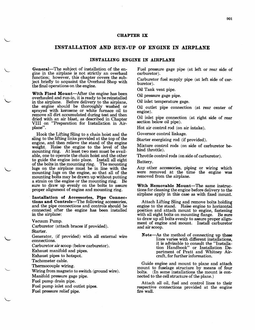
901
CEAPTER IX
INSTALLATION AND RUN-UP OF ENGINE IN AIRPLANE
INSTALLING ENGINE IN AIRPLANE
General-The subject of installation of the en-gine in the airplane is not strictly an overhaulfunction; however, this chapter covers the sub-ject briefly to acquaint the Overhaul Shop withthe final operations on the engine.
Wtth Flxed Mount-After the engine has beenoverhauled and run-in, it is ready to be reinstalledin the airplane. Before delivery to the airplane,the engine should be thoroughly washed orsprayed with kerosene or white furnace oil toremove all dirt accumulated during test and thendried with an air blast, as described in ChapterVIII on "Preparation for Installation in Air-plane".
Hook the Lifting Sling to a chain hoist and thesling to the lifting links provided at the top of theengine, and then relieve the stand of the engineweight. Raise the engine to the level of themounting ring. At least two men must be avail-able, one to operate the chain hoist and the otherto guide the engine into place. Install all eightof the bolts in the mounting ring. The mountinglugs on the airplane must be in line with themounting lugs on the engine, so that all of themounting bolts may be drawn up without puttinga strain on the engine or the mounting ring. Besure to draw up evenly on the bolts to assureproper alignmerrt of engine and mounting ring.
Installatlon of Accessorles, Ptpe Connee-tlons and Controls-The following accessories,and the pipe connections and controls should beconnected after the engine has been installedin the airplane:
Vacuum Pump.Carburetor (attach braces if provided).Starter.Generator, (if provided) with all external wireconnections.Carburetor air scoop (below carburetor).Exhaust manifold and pipes.Exhaust pipes to hotspot.Tachometer cable.Thermocouple wiring.Wiring from magneto to switch (ground wire).Manifold pressure gage pipe.Fuel pump drain pipe.Fuel pump inlet and outlet pipes.Fuel pressure relief pipe.
Fuel pressure gage pipe (at left or rear side ofcarburetor).Carburetor fuel supply pipe (at left side of car-buretor).Oil Tank vent pipe.
Oil pressure gage pipe.
Oil inlet temperature gage.
Oil outlet pipe connection (at rear center ofengine).Oil inlet pipe connection (at right side of rearsection below oil pipe).
Hot air control rod (on air intake).Governor control linkage.Starter energizing rod (if provided).
Mixture control rods (on side of carburetor be-hind throttle).Throttle control rods (on side of carburetor).Battery.Any other accessories, piping or wiring whichwere removed at the time the engine wasremoved from the airplane.
Wlth Rem.ovable Mount-The same instruc-tions for cleaning the engine before delivery to theairplane apply in this case as with fixed mount.
Attach Lifting Sling_and remove bolts holdingengine to the stand. Raise engine to horizontalpositioq and attach mount to engine, fastettingwith all eight bolts on mounting flange. Be sureto draw-up all bolts evenly to assure proper align-ment of engine and mount. Install carburetorand air scoop.
Note-As the method of connecting up theselines varies with different installations,it is advisable to consult the "Installa-tion Handbook" or Installation De-partment of Pratt and Whitney Air-craft, for further information.
Guide engine and mount to plane and attachmount to fuselage structure by means of fourbolts. (In some installations the mount is con-nected to the cell structure of the plane.)
Attach all oil, fuel and control lines to theirrespective connections provided at the enginefue wall.
902INSTALLATION AND RUN.UP OF ENGINE IN AIRPLANE
Flxed Pltah, Controllable' Constant Speedand Eydromatlc Propellers-Complete in-structions for the installation of these propellersare given in the service manual issued by thepropbller manufacturer, and this manual shouldbe cbnsulted before installation.
Run-up of Englne ln Alrplane-The generalpurpose of the run-up of the engine in the airplaneis tb insure that the installation is functioningnormally and that the engine operating charac-teristics are satisfactory. The duration of therun-up period should be at least thirty minutesand preferably an hour.
Ground Runnlng Preaautlons-Enginesequipped with pressure baffies can be severelyol:erhbated wheir running on the ground unlessextreme care is exercised. The effectiveness ofpressure cooling is dependent on the forwardspeed of the plane building up a positive pressurein front of the engine cylinders, and a negativepressure behind the cylinders thereby forcingthe cooling air between the fins. When runningup an engine against the blocks, the flow of airis very much reduced, so that unless the power isIimited the cylinders will overheat.
It is recommended that at least two cylinderhead thermocouples be installed and that, whenwarming up, the temperature should not beallowed to exceed 400" F. (204" C.). Themaximum R. P. M. possible within this 400o F.(204" C.) limit will vary with different installa-tions and propellers, so that for a given airplaneit is good practice to determine what limitingR. P. M. under average conditions is necessary as
an added protection against overheating. It isgenerally possible, however, to warm up theengine at the usual 1000 R. P. M.
When opening the throttle further to checkthe R. P. M. and magnetos, the cylinder headtemperature should not be allowed to exceed500'tF. (260" C.) in the short burst. The cylin{ertemperatures are likely to increase rapidly afterpassing 400o F. (204" C.).
Where it is found necessary to give a newlyinstalled engine a prolonged ground run-up,- thering cowl and int-er-cylinder bafles should beremoved as an aid to cooling.
After this run-up, the oil strainer should becleaned to remove any foreign matter whichmight have come from the tank or pipes of theairplane. Check all installations and controls tosee that everything is satisfactory.
Adjustment of OII Pressure Rellef Valve-To
-adjust the pressure turn the adjgsting screw
with a screw diiver, until the desired pressure isobtained. The valve is adjusted at the factoryto give ?0-90 pounds pressure at rlted sp$when the oil inlet tempeiature is 140o F. (60'C.).When testing an eng-ine in a new installation,the pressure should be checked and, if_necessary,adjusted to give the above-mentioned pressure.However, wh-en the relief valve is once set for aparticular airplane, readjustment to care forvariatiotts in pressure is irot advocated. If thepressure drops abnormally, it is recommendedttrat the cause be determined rather than thatthe relief valve be readjusted.
1001
CEAPTER X
GUN SYNCERONIZERS
DISASSEMBLY
Unscrew cam follower cap and lock plunger orplug from gun'synchronizer cover, using suitablewrenches. Unscrew four cap screws which fastenzun synchronizer cover; then remove cover andittim.- Withdraw cam-follower, cam and gearshaft, bearings and bearing retainer as a unitfrom housing. Remove cotter pin, nut and bolt
The following parts should be inspected visu-ally for the various conditions as outlined:
Gun synchronizer housing cover for cracks,mutilations and condition of paint.
Cam follower, cam and gear teeth for evidenceof wear.
Balt bearing retainer for free fit in housing.
Dowel pin hole for proper depth.
REPAIR ANI)
Press lower ball bearing on cam and gear shaft.Fit upper ball bearing in bearing retainer andinsert cam follower in hole of retainer. Pressupper ball bearing on cam and gear shaft. Toperform this operation it is necessary that rollerand cam follower be placed between lobes ofcam. Secure the ball bearings and bearing re-tainer on the shaft by means of the bolt, washer,nut and cotter pin. Install the cam follower,cam and gear shaft, bearings and bearing retainerin the housing as a unit. Place laminated shimover gun synchronizer cover mounting flangeand housing, and fasten cover in proper positionon housing with four cap screws. Insert a smallscrew in the tapped hole at the end of the camfollower; then pull follower to the top ofthe stroke. Screw lock plunger in cover insuringthat it seats properly in notch of cam follower.
It may be necessary to move cam followerslightly to permit engagement of plunger innotch. Care must be exercised not to jamplunger when it is installed. In the event thatthe plunger will not enter, it should be removedtogether with the cam, and the width of the notchshould be checked.
CLEANING
All parts of the gun synchronizer may be cleaned with white firrnace oil. (Specific Gravity 38-40.)
INSPECTIOIT
from cam and gear shaft. Remove retainer andupper bearing from cam and gear shaft by tap-ping on end of shaft with a dural drift andhammer; then remove cam follower. The bear-ing may be pushed out of retainer with fingersafter both of these parts have been removed fromshaft. Remove lower bearing.
Ball bearing as described in Chapter IV,Inspection.
Be sure that the lock plunger is of such a widththat it will fit in notch of cam follower to thedesired clearance. This plunger must not berounded at the end, as if such were the case itwould not seat properly in notch of cam follower.
Be sure that the cam follower slides freely inits respective holes in the housing.
ASSEMBLY
If the end of the lock plunger becomes jammed,do not attempt to correct this condition by filingthe burred edges on the plunger, as in so doingthe plunger may become sufficiently reduced indiameter to render it a loose fit in notch. Sincea loose fit will seriously affect clearance betweencam and roller on cam follower, a plunger whichis damaged at the end should be replaced with anew plunger.
Remove inspection cover plate on housing(after lock plunger is installed) and check clear-ince betwebn cim and roller on cam follower.This clearance must be in accordance with thatspecified in the Tables of Clearances and shouldb-e adjusted (if necessary), by adjusting thelaminated shim beneath the gun synchronizercover to provide the proper clearance. On latersynchronizers an ecc'entric sleeve on the lockplunger is used to adjust the clearance betweenlhe c-am follower and the cam. This should beturned until the desired clearance is obtainedbetween the cam and cam follower. Be sure thatthe inspection plate is installed after clearanceis checked.
Remove the screw in the end of the cam fol-
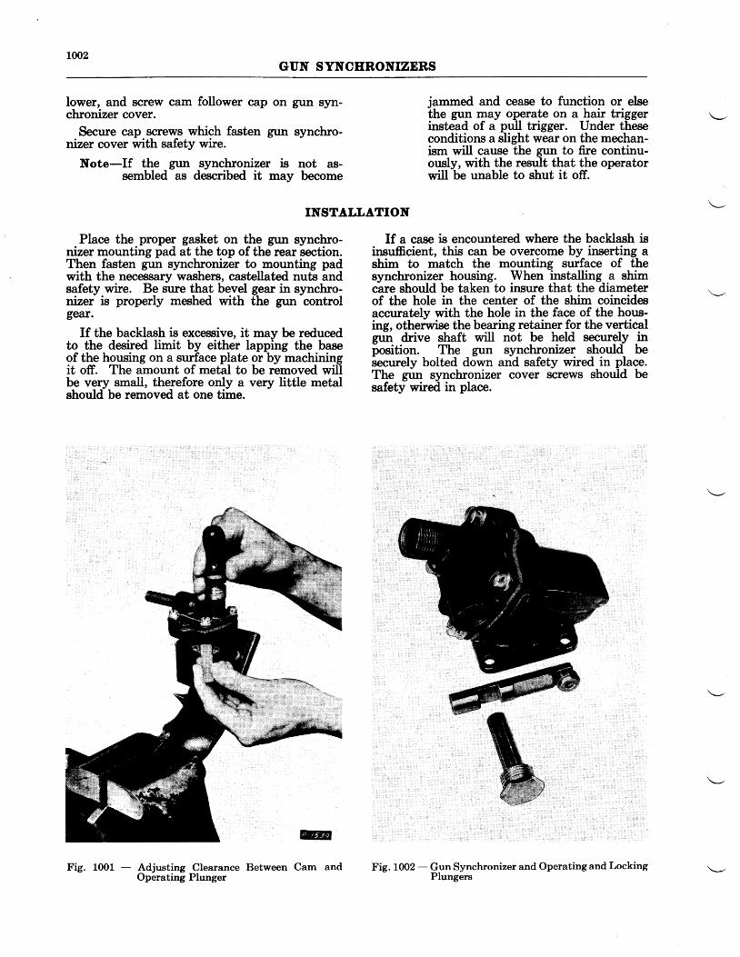
1002GUN SYNCERONIZERS
lower, and screw cam follower cap on gun syn-chronizer cover.
Secure cap screws which fasten gun synchro-nizer cover with safety wire.
Note-If the gun synchronizer is not as-sembled as described it may become
jammed and cease to function or elsethe gun may operate on a hair trigger \--instead of a pull trigger. Under theseconditions a slight wear on the mechan-ism will cause the gun to fire continu-ously, with the result that the operatorwill be unable to shut it off.
INSTALLATION
Place the proper gasket on the gun synchro-tizer mounting pad at the top of the rear section.Then fasten gun synchronizer to mounting padwith the necessary washers, castellated nuts andsafety.wire. Be sure that bevel gear in synchro-nizer is properly meshed vrith the gun controlgear.
If the backlash is excessive, it may be reducedto the desired limit by either lapping the baseof the housing on a surface plate or by machiningit off. The amount of metal to be removed willbe very small, therefore only a very little metalshould be removed at one time.
If a case is encountered where the backlash isinsufficient, this can be overcome by inserting ashim to match the mounting surface of thesynchronizer housing. When installing a shimcare should be taken to insure that the diameterof the hole in the center of the shim coincideaccurately with the hole in the face of the hous-ing, otherwise the bearing retainer for the verticalgr" drive shaft will not be held sqcurely inposition. The gun synchronizer should besecurely bolted down and safety wired in place.The gun synchronizer cover screws should besafety wired in place.
Fig. 1002 - Gun Synchronizer and Operating and LockingPlungers
Fig. 1001 - Adjusting Clearance Between Cam andOperating Plunger
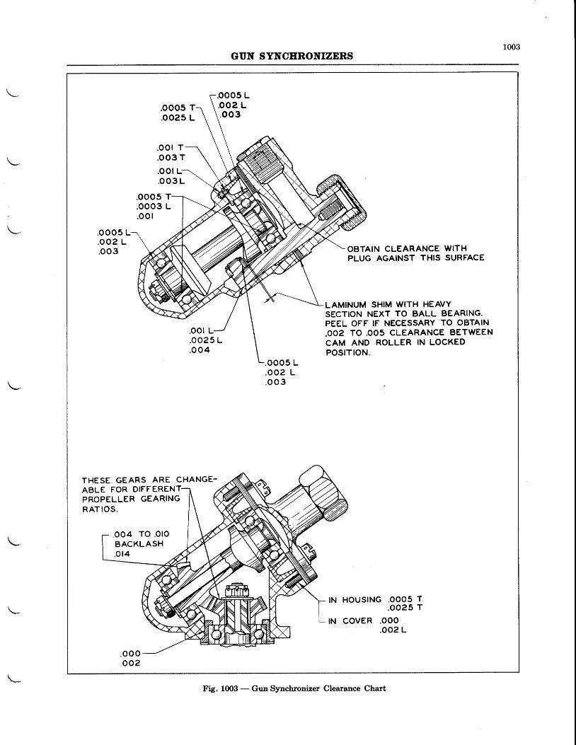
1003GUN SYNCERONIZERS
.ooo5 T
.oo25 L
.ooo5 Loo2 L.oo3
.oor T
.oo3 T
.ooo5 T
.ooo3 L
.oo I
.OOO5 ul
. o02 L.oo3 OBTAIN CLEARANCE WITH
PLUG AGAINST THIS SURFACE
.oor L
LAMINUM SHIM WITH HEAVYSECTION NEXT TO BALL BEARING.PEEL OFF IF NECESSARY TO OBTAIN.OO2 TO .OO5 CLEARANCE BETWEENCAM AND ROLLER IN LOCKEDPOSITION.
. oo25 L
.o o4.ooo5 L.oo2 L. o o 3
THESE GEARS ARE CHANGE-
oo4 TO .OlOBACKLASH.ot4
IN HOUSING .OOO5 T.oo25 T
tN covER .ooo.oo2 L
.oot L-
ABLE FOR DIFFERENTPROPELLER GEARINGRAT IOS.
Fig. 1003 - Gun Synchronizer Clearance Chart
1101
CEAPTER XI
SPARK PLUGS
GENERAL
Spark plugs should be inspected and testedeach time they are removed from an engine. Thenumber of hours between these inspection periodsdepends a great deal upon the type of operationto which the plugs are subjected, the rate of elec-trode gap increase usually being the determiningfactor. In general, operators set up inspectionand reconditioning procedures to suit their in-dividual requirements. However, it is recom-
CLEAIYIIIC AND
It ls _v_ery seldom necessary and definitelyundesirable to complefsly disassemble sparkplugs at every periodic inspection. Under normalconditions, such as a scheduled operation wherecontrol is rigidly maintained, the following serviceprocedure is recommended.
Spark plugs should be installed in the engineas received, and operated until the tips of-thecenter electrodes have been reduced toapproxi-mately the manufacturer's specified miirimumdiameter or the ground electrodes to the mini-mum thickness, b"!rg removed only for inspec-tion at the prescribed periods and serviced asoutlined in this section. Before installing theplugs, a light coat of mica lubricant should beapplied to the threads, and before screwing theplug into the cylinder, inspect the spark plugbushing threqds to make sure they are absolutelyclean. Use fully annealed solid copper gasketsthat are in good condition. Do not use old gas-kets which have become hard, distorted, or burredfrom previous service. Care is to be exercised inpreventing excssive force being used whentightening the plugs in the cylinder. The pressureexerted should not exceed 450 inch poundswhen cold, (approximately 37 foot pounds).
Spark plugs are to be removed from the en-gines at the prescribed inspection periods atwhich time they are to receive the followingmaintenance wlthout belng dlsassembled.
Lightly brush the threads and end of the shellusing a soft wire brush. Do not use excessivepressure as it will tend to round offthe electrodes.
Inspect shell threads for nicks and burrs. Chasevyith 18 mm die when necessary.
Inspect top barrel threads for nicks and burrs.Chase with s4-27, or 5f-24,, die when neces-sary.
mended that the spark plug manufacturer beconsulted as to details in connection with theparticular make and model spark plug in use.
The following instructions treat with the rec-ommended procedure for servicing spark plugs ina general manner. For specific instructions andtools for the different makes and types of plugs,the respective manufacturers should be calledupon.
INSPECTION
Thoroughly rinse the electrode end of the oilyplugs in clean, unleaded gasoline. Do not holdthe plugs immersed in the gasoline and if they arenot coated with dirt or oil film, this operationmay be eliminated. The blackened appearanceat the end of the plug in the absence of heavyoil or lead deposit is not detrimental to its opera-tion. This is acquired after a few minutes ofoperation in the engine. Permit the plugs to drythoroughly after rinsing.
Clean the inside of the upper shielded barrel.For this operation, use a smali piece of soft clothwound on a wooden stick dipped in clean, ur-leaded gasoline.
To remove moisture bake all plugs in an ovenat 300o F. to 350o F. (149" C.:177" C.) for aperiod of two hours or more.
Set the gaps to the recommended .0L2" clear-ance, using a flat, narrow width thickness leafgage.
Check the electrode gaps using a wire feelergage.
Bomb test aI spark plugs set at .0t2" gap.at 200 lbs./sq. in. For this purpose use COior air, where an adequate and dependable sup-ply of dry, high pressure air is available.
After the above work has been completed, careis to be taken when storing the spark plugsawaiting installation in the engine. To preventrusting, plugs should be coated with a light oil orsuitable rust inhibitor. Be careful not to alloweither the oil or the compound to enter theshielded banel or the inside shell around the noseof the core. In order to keep the plugs clean, andprevent moisture absorption, they should becovered by protecting caps screwed on both theshell and the barrel thread. The top or shieldedbarrel cap should be equipped with an internal
LLO2SPARK PLUGS
gasket to insure an air-tight seal. As an addedprecaution, plugs should be stored in a heatedcompartment.
This procedure is to be repeated at each perioduntil the limiting factors outlined previously are
RECONDITIONING
In the event that the conditions of operationare such that it should require some recondition-ing by the operator, the following procedureshould be followed:
Dlsassembly-Spark plugs should be disas-sembled, using snug-fitting socket wrenches.Open end wrenches should never be used as theyar-e liable to slip and cause damage.
If the threads securing the core and shell to-gether have a tendency to bind during the dis-assembling procedure, do not attempt to force thethreads. Place the plugs in a rack, electrode endup, and pour a very small quantity of penetratingoil in the firing chamber. Place the plugs in aheat regulated oven with temperature main-tained between 150' F. and 200o F. (66" C.-93o C.) for at least twenty-four hours. Thisprocedure will facilitate the disassembly in mostcases. If difficulty is still experienced, it may be-come nece$sary to scrap the parts.
Shell Assembly-Where large quantities ofshells are being serviced and the facilities areavailable, removal of carbon and lead depositsis best accomplished by placing the shells in aheated salt bath, or a similar preparation whichis recommended by the manufacturer. In smallquantities, they may be soaked in clean, unlqqdedsrasoline to remove the oil and carbon. Harddarbon and lead deposits may be removed with aknife or round wire brush. A small wad of steelwool wound on a drill and used in a lathe or drillpress chuck is also effective in cleaning the insideof the shell. Care should be taken to preventdamage to the internal threads, the core gasketseat, and electrodes.
Rust may be removed by dipping in a L0%solution of suplhuric acid at L20o F. (49" C.)for a few minutes and then rinsing in cold runningwater. After drying, coat the shells with a lightoil, or suitable rust inhibitor.
All shells should be inspected for damagedhexagons, condition of the electrodes and bunedthreads. Damaged threads should be cleaned upwith a tap or die, or in some cases with a file.
When the shell electrodes are burnt away inexcess of the manufacturer's limit and can nolonger be properly adjusted, they should be dis-carded and new shells used. On some makes, newelectrodes may be inserted, as long as the shell isin otherwise good condition.
reached, at which time those makes of sparkplugs which can have the center electrodes re-tipped or new shells to replace the ground elec-trbdes installed , are to be returned to the manu-facturer, otherwise the plugs are to be discardedas unserviceable.
OF SPARK PLUGS
Core Assembly-Check the core assembly fordefects. If the %6-27" or sl-24" elbow attachingthreads at the shielded end of the plug are crossedor badly damaged, the core should be scrappedinasmuch as there would not be positive assur-ance that the elbow would be secured firmly inplace. Small nicks or burrs can be cleaned up byiunning a die over the threads, or with a tool-maker's file.
Check the mica insulation in the upper barrelfor defects, such as deep scratches or gouging.Minor scratches are permissible. However, deepscratches or gouging may develop trouble lateron. A definite crack in the insulation should because for rejection. Remove all traces of dirt andoil, etc. from within the shielded barrel. A smallround wooden stick, or dowel, with severallayers of clean cloth wrapped around it anddibped in clean, unleaded gasoline proves effec-tive for cleaning the inside of the barrel.
Examine the core threads for nicks, pitting,forms of corrosion, or mutilation. Small nicks orpits can usually be stoned out or removed witha fine toolmaker's file. Threads which are badlyscuffed, during disassembly, are cause for rejec-tion. Corrosion, if not too severe, may be toler-ated. Check the amount of metal left on the cen-ter electrode shoulder in accordance with themanufacturer's instructions, and if worn in ex-cess of the manufacturer's limit, the core shouldbe scrapped.
To remove the lead deposits which have accu-mulated on the mica core nose, it is recom-mended that the core be inserted in a motor-driven cleaning socket and revolved at a speed ofapproximatelyl750 R. P. M. Sockets for the vari-oG plugs should be obtained from lhe respectivespar-k blue manufacturers. Preferably gradeNo. 180 Aloxite cloth should be used for thisproce$s. However, J''{o. 0_0 sa4dpaper will- alsoserve the purpose. Lead deposits are not of uni-form hardnesii or equally distributed; hence itis possible that some sections on the core nosemay offer greater resistance to removal than othersections.
-For this reason, the operator is cau-
tioned not to exert too much pressure on thecloth in the early stages of cleaning. Followingthe removal of the carbon, lead deposit, etc.,polish the mica using No. 300 Aloxite cloth orNo. 000 Crocus cloth-in order to obtain a smoothfinish. The operator is cautioned not to removeany more mica insulation than is absolutely nec-
1103SPARK PLUGS
essary to obtain a clean and well-polished corenose. Never use emery or carborundum cloth orpaper, steel wool, file or sandblasting, as it is det-limental since particles from these materialsmight affect the plugs in the event that they be-come imbedded in the mica insulation. Sand-blasting is too harsh on mica insulation andwould wear away the insulation at a rapid rate.
Care should be taken during the core nosecleaning operation to prevent unnecessary wearof the center electrode tips.
If there is sufficient metal left upon the centerelectrode tip, it can be rounded off by insertingthe core in the chuck of a motor-driven lathe andturning down the tip. Ottly enough material toobtain a smooth finish should be removed. Thetip should be rechecked for contour after thisoperatron.
On certain types of plugs, it is possible to retipthe center electrodes when worn to an extent thatthev exceed the manufacturer's limits. In thisresiect, the manufacturer should be consulted.
Examine the clean mica core nose surfaces forpits, burned areas, or unusual wear. Evidence ofanv one of these defects should be cause forrei-ection. Check the diameter of the core nosie,using the gage provided by the manufacturer. Ifthe mica diameter adjacent to the core tip passesthrough the narrow part of the opening in thega1e,lhe, insulation has worn apay beyond theSafe point and is cause for rejection.
Assembly-Using mica lubricant sparingly, onthe lower threads, assemble the core into theshell of the plug. Normal tightening is sufficient.Over-tightening will only distort the core and per-haps damage it. The manufacturer of the par-ticular spark plug should be consulted for thetorque limits which generally is never in excess of3501n.-lbs. (approximately 29 foot pounds).
Bornb Tests-After assembly, the spark plugsshould be tested in a pressure tester or bomb testat200lbs./sq. in. of COz. Air may be used pro-viding special precautions are taken to excludeany moisture.
All new or reconditioned spark plugs should
F" r"grrlarly across the .0L2" g?p.at 200 lbs./sq.in. pressure. The duration of the test shouldbe
-approximately fifteen seconds. If any
plugs fail to fire consistently at this pressure,theie may be a possibility of moisture having
collected on the core nose or in the shield cham-ber. Place such plugs in a heat regulated ovenand bake them for approximately two hours at250" F. to 350' F. (LzL' C.-I77o C.). Retestthem after they have cooled sufficiently forhandling. If they still fail to fire consistentlyafter the operator has assured himself that thetest equipment is operating satisfactorily, andthat the flash-over is not occurring within theshield chamber, the plug is short-circuited andshould be rejected.
Practice is required to determine when a plugfires regularly in a bomb. With some types ofplugs, the spark "hunts" from one electrodeiroint'to another, firing across the point havingthe least resistance at the instant. To an inex-perienced operator this hunting might appear tobe a t'miss".
After testing, the plugs should be coated witha light oil or a suitable rust inhibitor to pre,ventconosion, and protector caps installed on bothends of the plug.
To avoid the effects of moisture, spark plugsshould always be stored in a dry place. This isparticularly important during the winter periodsor damp weather. A cabinet, or a box, heatedwith one or more 100 watt electric light bulbsprovides a suitable storage place.
Terrnlnal Sleeves-Particular care should beexercised when installing the termir:al sleeveson the ignition wire. Cut just the specifiedamount of insulation from the conductor to per-mit the right length of wire to extend throughthe wire outlet. The insulation must bear firmlyagainst the brass disc on the inside end of thesleeve. The ends of the ignition wires, con-structed with a layer of cotton under the lac-quered surface, should be dipped in an insulatingvarnish to about /s", and permitted to dry beforeterminal sleeves are applied to the wire. Thistreatment prevents the layer of cotton from act-ing as a wick should moisture find its way intothe assembly. When installing the terminal inthe plug it should be wiped perfectly cleaa, andaftei that not touched by the fingers as oil, acid,dirt, etc., will promote flashover, cause de-terioration, and
-eventual failure of the sleeve.
The repeated installation of dirty sleeves in aspark plrrs results in contaminatlng the micainsulation on the inside of the barrel, whicheventually will cause faulty operation.
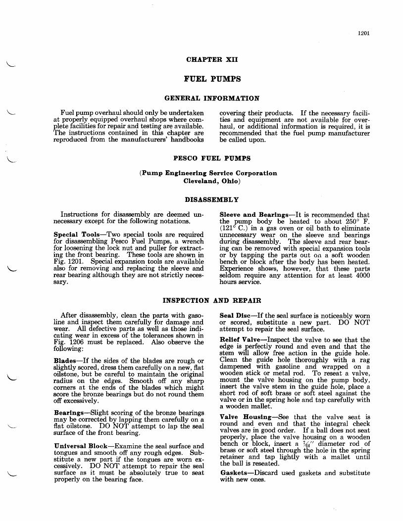
t20L
Iruel pump overhaul should only be undertakenat properly equipped overhaul shops where com-plete facilities for repair and testing are available.Ihe instructions contained in this chapter arereproduced from the manufacturers' handbooks
CEAPTER XII
FUEL PUMPS
GENERAL INFORMATION
PESCO FUEL PUMPS
(Pump Englneerlng Servlce CorporatlonCleveland, Ohto)
DISASSEMBLY
covering their products. If the necessary facili-ties and equipment are not available for over-haul, or additional information is required, it isrecommended that the fuel pump manufacturerbe called upon.
Instructions for disassembly are deemed un-necessary except for the following notations.
Speclal Tools-Two special tools are requiredfor disassembling Pesco Fuel Pumps, a wrenchfor loosening the lock nut and puller for extract-ing the front bearing. These tools are shown inFig. 120I-. Special expansion tools are availablealso for removing and replacing the sleeve andrear bearing although they are not strictly neces-sary.
INSPECTION
After disassembly, clean the parts with gaso-line and inspect them carefully for damage andwear. All defective parts as well as those indi-cating wear in excess of the tolerances shown inFig. 1206 must be replaced. Also observe thefollowing:
Blades-If the sides of the blades are rough orslightly scored, dress them carefully on a new, flatoilstone, but be careful to maintain the originalradius on the edges. Smooth off any sharpcorners at the ends of the blades which mightscore the bronze bearings but do not round themoff excessively.
Bearlngs-'Slight scoring of the bronze bearingsmay be corrected by lapping them carefully on aflat oilstone. DO NOT attempt to lap the sealsurface of the front bearing.
Unlversal Block-Examine the seal surface andtongues and smooth off any rough edges. Sub-stitute a new part if the tongues are worn ex-cessively. DO NOT attempt to repair the sealsurface as it must be absolutely true to seatproperly on the bearing face.
Sleeve and Bearlngs-It is recommended thatthe pump body be heated to about 250o F.(LzL" C.) in a gas oven or oil bath to eliminateunnecessary wear on the sleeve and bearingsduring disassembly. The sleeve and rear bear-ing can be removed with special expansion toolsor by tapping the parts out on a soft woodenbench or block after the body has been heated.Experience shows, however, that these partsseldom require any attention for at least 4000hours service.
AND REPAIR
Seal Dtsc-If the seal surface is noticeably wornor scored, substitute a new part. DO NOTattempt to repair the seal surface.
Rellef Valve-Inspect the valve to see that theedge is perfectly round and even and that thestem will allow free action in the gurde hole.Clean the guide hole thoroughly with a ragdampened with gasoline and wrapped on awooden stick or metal rod. To reseat a valve,mount the valve housing on the pump body,insert the valve stem in the guide hole, place ashort rod of soft brass or soft steel against thevalve or in the spring hole and tap carefully witha wooden mallet.
Valve Eouslng-See that the valve seat isround and even and that the integral checkvalves are in good order. If a ball does not seatproperly, place the valve housing on a woodenbench or block, insert a %t" diameter rod ofbrass or soft steel through the hole in the springretainer and tap lightly with a mallet untilthe ball is reseated.Gaskets-Discard used gaskets and substitutewith new ones.
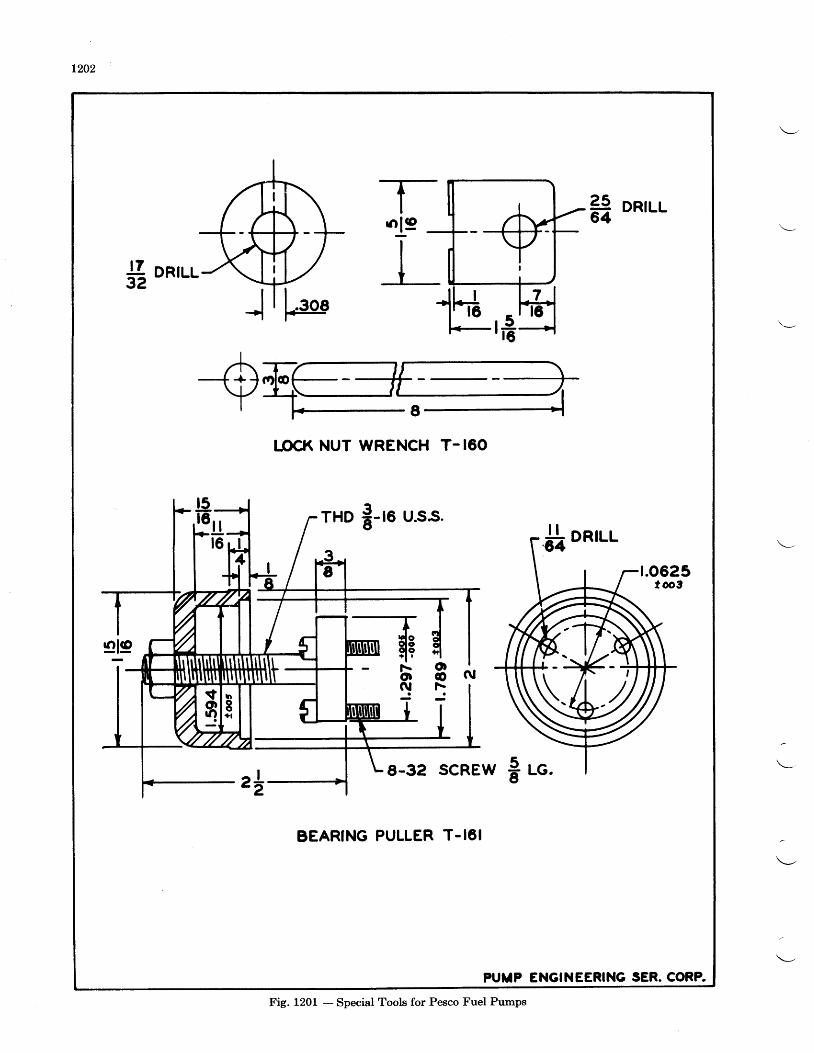
L202
.19IIt
2564
DRILL
LOCK NUT WRENCH T- 160
rHD 8-'. u.ss."jI onrur-
t.0625tooS
oo\
N
s-32 scREw I .o.
BEARING PULLER T-16I
PUIIP ENGINEERING SER. CORA
Fig. 1201 - Special Tools for Pesco Fuel Pumps
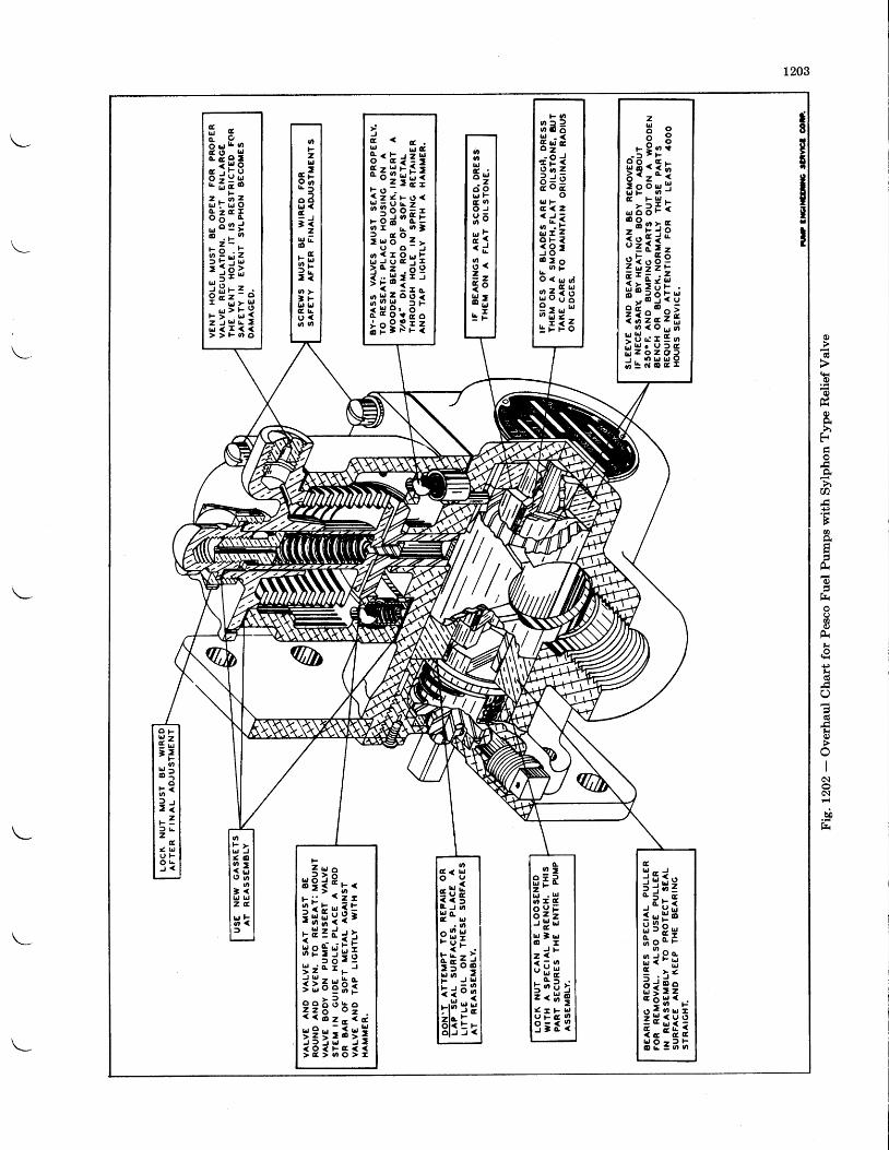
1203
c)
o
o)
hF
h0
+)
Fo
Ha
r-.
oo)
t{
d+)fr
7
lr
o{
c\
b!
s8
TE
iTxI
5 ' 8:!frL'| Lt L ,
:Ii ,i 5 6 df , ' t ' -
ff;;6l tE"o l J J <
a g- 5 ; p ":E :T I; g " H j
I e l E tl s p r s
!it;;fi:5r f szi'zrZll U c r 9 oq H i ; i 56 E c o c -
l-lr'|
3 e =Eg ;r P ig u r z
i d ga22< c i
I i=i 8 :@ > o, . t Fo < r . l s f
s63HH ; s l: E F 6
f *3 , E ,
;;gfiz . i zU J I - L r o
: E;5@ . t - o
i i l ;u =
i E : : air!H:
J
H;ili:i 9 ; r o .
; ;5: f ii s E i = 3q; t i3E
lxiiil
oFzLJ
" 79 i tE f
o Blrl <t
; iz
t ! L@
. 9 .
; g3 io >] r 'lr, L,C Lu <6 t n
0olrl
E ic i o!,1 FG oO J
3 6- , :- c3 .? zi os ;g I
O F
E=.- I
F
an
H lo
h <l r: lr Z] l |z
g,
< uI J FO L) <
oF plr., J< . O
? ;9 3 n
o] <LJ LJz c
H ID
F
H e : p , .
i ; ; l ; i; ;s liiS i c r r . ,
3 i a 6 ; 3??g : :? ,:3:*;::
l;l;H:Ei[ :PfrEai=,,i i ; ;:H 8 = ? h
s i iH ; Hq;EB } H
J Fz <J H E_ o . ii . t U lz . A g< I F r yq ;3 I
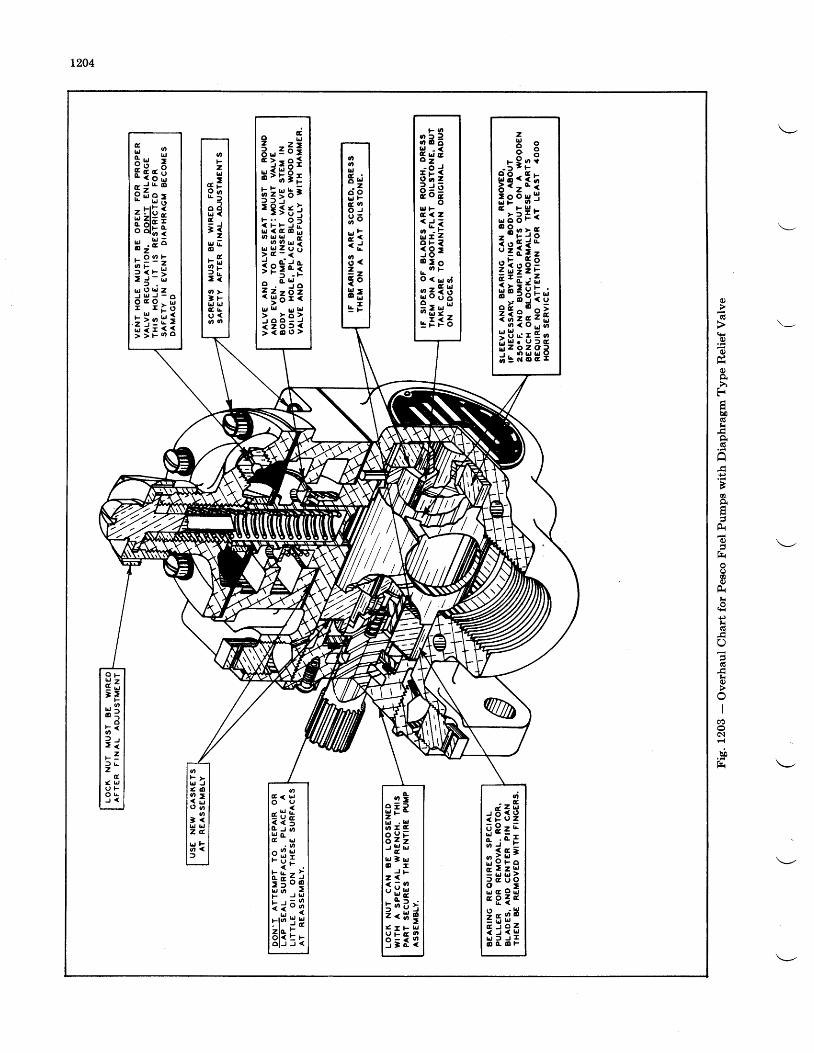
L204
tt
Ftrh0
hg
+)
Ba
F,
()a
@
Fr
+)r.{
kq)
II
c\
bb
Fr
t s . n
3 e 3Hg;; 9 i9 r a � zp d gH T :. d 3
f ; i=i 8 'o > o, . ' Fo < u g f
s 6 3 gH ; s lc I f 6
i,;sl! ; : ; ;
IIEiH3 e $;.3?rr l :iln:1
.r !* i; ; ; ; ;I e lE r3![ : :2EzE?
;*lil;{ U e r E o
3;i;EF
F TEEsia j t @
8 0 F ;
gH;rH ; H -r 99 r -
3 ; :Et r l ( , t J Z
d H d . g! i : ; i
oFzlrJ
. . i8 go Bl ! <E
; iz
trt E@. G7ry3 ro >] r!J |.JG l |u <. o o
tt,ordEzc ioL ' Ft oO JH 6= <- c3 <2 _- -t oH ;g F
O F
Efr= >
F6
B :o
; <J r> ir 7: ) L
zI
< uU FO t !J <
oF yt d J( . 09 ,A L Jg 6
o- <lrJ L,Z G
u Fo <
d < b ,O U
- r f ,
r3 ;lrJ Gg trJ
s [ !gseiu 6 .F ) b t
: ; ; ;alt E'-o l J J <
a i3z 'Lr . lr,. n t E
i,'r"EH } H
J Fz <JHf i: : * l( r F u
q : i 1
rfiEHq=;
si;iEr:E3s[1; j j 1O G O F
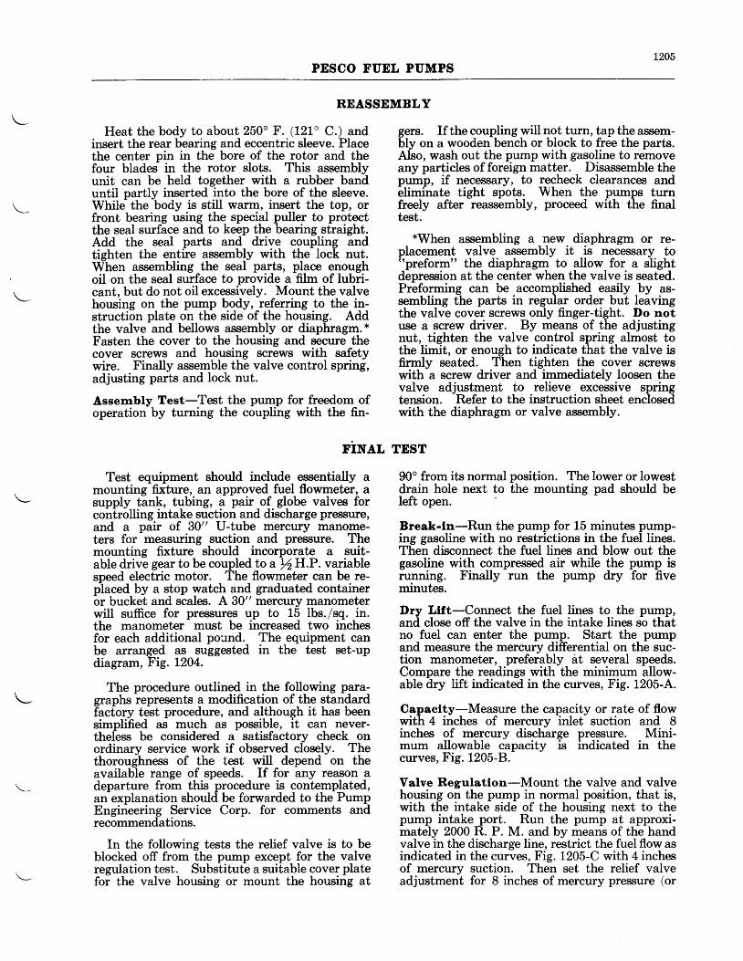
L205PESCO FUEL PUMPS
REASSEMBLY
Heat the body to about 250" F. (121" C.) andinsert the rear bearing and eccentric sleeve. Placethe center pin in the bore of the rotor and thefour blades in the rotor slots. This assemblyunit can be held together with a rubber banduntil partlv inserted into the bore of the sleeve.While the body is still warm, insert the top, orfront bearing using the special puller to protectthe seal surface and to keep the bearing straight.Add the seal parts and drive coupling andtiehten the entire assembly with the lock nut.When assembling the seal parts, place enoughoil on the seal surface to provide a film of lubri-cant, but do not oil excessively. Mount the valvehousing on the pump body, referring to the in-struction plate on the side of the housing. Addthe valve and bellows assembly or diaphragm. *Fasten the cover to the housing and secure thecover screws and housing screws with safetywire. Finally assemble the valve control spring,adjusting parts and lock nut.
Assernbly Test-Test the pump for freedom ofoperation by turning the coupling with the fin-
rilYer.,
Test equipment should include essentially amounting fixture, an approved fuel flowmeter, asupply tank, tubing, a pair of globe valves forcontrolling intake suction and discharge pre$sure,and a pair of 30" U-tube mercury manome-ters for measuring suction and pressure. Themounting fixture should incorporate a suit-able drive gear to be coupled to a ftH.P. variablespeed electric motor. The flowmeter can be re-placed by a stop watch and graduated containeror bucket and scales. A 30" mercury manometerwill suffice for pressures up to 15 lbs./sq. in.the manometer must be increased two inchesfor each additional pound. The equipment canbe arranged as suggested in the test set-updiagram, Fig. 1204.
The procedure outlined in the following para-graphs represents a modification of the standardfactory test procedure, and although it has beensimplified as much as possible, it can never-theless be considered a satisfactory check onordinary service work if observed closely. Thethoroughness of the test will depend on theavailable range of speeds. If for any reason adeparture from this procedure is contemplated,an explanation should be forwarded to the PumpEngineering Service Corp. for comments andrecommendations.
In the following tests the relief valve is to beblocked off from the pump except for the valveregulation test. Substitute a suitable cover platefor the valve housing or mount the housing at
gers. If the coupling will not turn, tap the assem-bly on a wooden bench or block to free the parts.Also, wash out the pump with gasoline to removeany particles of foreign matter. Disassemble thepump, if necessary, to recheck clearances and6liminate tight spots. When the pumps turnfreely after reassembly, proceed with the finaltest.
*When assembling a new diaphragm or re-placement valve assembly it is necessary to"preform" the diaphragm to allow for a slightdepression at the center when the valve is seated.Preforming can be accomplished easily by as-sembling the parts in regular order but leavingthe valve cover screws only finger-tight. Do notuse a screw driver. By means of the adjustingnut, tighten the valve control spring almost tothe limit, or enough to indicate that the valve isfirrnly seated. Then tighten the cover screwswith a screw driver and immediately loosen thevalve adjustment to relieve excessive springtension. Refer to the instruction sheet enclosedwith the diaphragm or valve assembly.
TEST
90o from its normal position. The lower or lowestdrain hole next to the mounting pad should beleft open. I
Break-ln-Run the pump for 15 minutes pump-ing gasoline with no restrictions in the fuel lines.Then disconnect the fuel lines and blow out thegasoline with compressed air while the pump isrunning. Finally run the pump dry for fiveminutes.
Dry Ltft-Connect the fuel lines to the pump,and close off the valve in the intake lines so thatno fuel can enter the pump. Start the pumpand measure the mercury differential on the suc-tion manometer, preferably at several speeds.Compare the readings with the minimum allow-able dry lift indicated in the curves, Fig. 1205-4.
Capaclty-Measure the capacity or rate of flowwith 4 inches of mercury inlet suction and 8inches of mercury discharge pressure. Mini-mum allowable capacity is indicated in thecurves, Fig. 1205-8.
Valve Regulatlon-Mount the valve and valvehousing on the pump in normal position, that is,with the intake side of the housing next to thepump intake port. Run the pump at approxi-mately 2000 R. P. M. and by means of the handvalve in the discharge line, restrict the fuel flow asindicated in the curves, Fig. 1205-C with 4 inchesof mercury suction. Then set the relief valveadjustment for 8 inches of mercury pressue (or
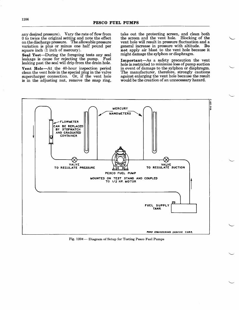
L206PESCO FUEL PUMPS
any desired pressure). Vary the rate of flow from0 to twice the original setting and note the effecton the discharge pressure. The allowable pressurevariation is plus or minus one half pound persquare inch (1 inch of mercury).Seal Test-During the foregoing tests any sealleakage is cause for rejecting the pump. Fuelleaking past the seal will drip from the drain hole.
Vent Eole-At the 4O-hour inspection periodclean the vent hole in the special plug in the valvesupercharger connection. Or, if the vent holeis in the adjusting nut, remove the snap dtg,
take out the protecting screen, and clean boththe screen and the vent hole. Blocking of thevent hole will result in pressure fluctuation and ageneral increase in pressure with altitude. Donot apply air blast to the vent hole because itmight damage the sylphon or diaphragm.
Important-As a safety precaution the venthole is restricted to minimize loss of pump suctionin event of damage to the sylphon or diaphragm.The manufacturer, therefore, strongly cautionsagainst enlarging the vent hole because the resultwould be the creation of an unnecessary hazard.
a
o
IM E R C U R Y
,.-txouerenT\
FLOWMETERCAN BE REPLACED
BY STOPWATCHAND GRADUATED
CONTAINER
F U E L S U P P L YTANK
tur.tp Eti tctNEEB|No sERylcE coRe
VALVE \ to\-6lol,/ VALVETO REGULATE PRESSURE /: 'TZI TO REGULATE SUCTION
PESCO FUEL PUMP
MOUNTED ON TEST STAND AND COUPLEDTO '/2 HP. MOTOR
Fig. 120a - Diagram of Setup for Testing Pesco Fuel Pumps
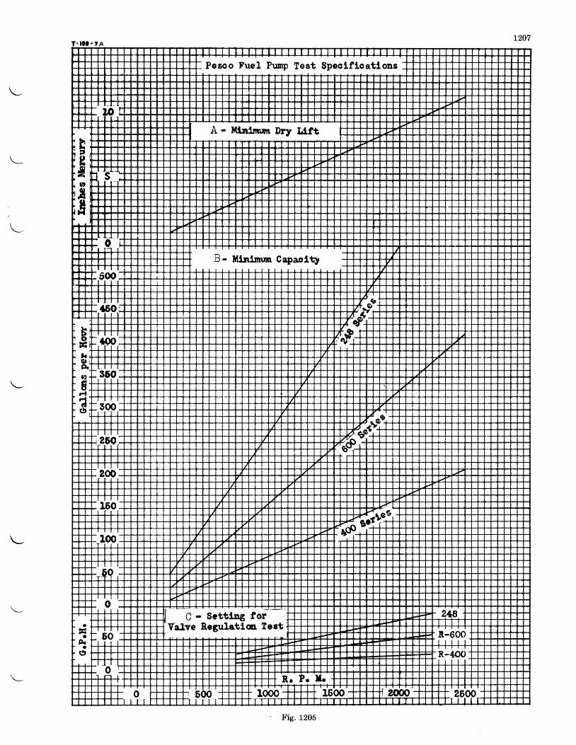
Fig. 1205
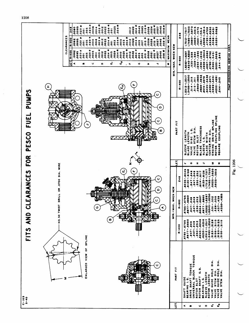
1208
(ooc\
bih
: lA i rer is ; !qHi t l i tg i i i ;g i ig ; iE
LJtI:tx:
'ldzzLla3it!
It
oiil
F 9 O 6 . ' - r ? O O - a
i i i i l t ! t I i i, t . l , 3 l i , i l ; l l l
! i i i i i ! q l q iI
u l ou l oz l o
i l *< l -
3lsgg sE s!a illq iE siisiagl sEiegig;;i g 5 - . : B = l s $ : s i : e n l ! . . !
r . - r - o re o r u o e q e e e e o o e e e o o e " 3 3 3 3 g t g S 8 3 3q q q q q q c c q q c q 9 q c q e c q q q q q q q c q q c q o
o|'I
c
l i i?r i i i i l i ig io i i ! ie i i i iI
$
ldz
c0tro
]Ll
oLll,cJzhl
Llc'jooog
Go
Eo
ntooct2
CI'o-=3o,JlrlDlr-
ou3nlrfg
G,o]L
3t,lrlu-
AE
lrJJ(,
o-
cnts1r-
! g6,1,
ootIc filIlltlilIt
!L
FE
f
2t d -- J
. o i $ t- - i * ! i ; : =
i i : l : i j ! ; ;g i; H a r s x i x l i s iL I < J J F < U < - O F fJ J < < O J J J | | | - o Ot a > > c 3 ' ' o u h t G t
t :ld b t ' a - r : z
!ld2zLlI'x
:I
i:
ot?cl
o o r 9 o o
?i r l i ; i l f? iq l i { i i i i t i
oooIciiiii?illi?i3r l i i { i ! ! ! q l11
ool?Iai i i i i i l iFii l ;1 F F t r o o . o . " p . l l l
; i i i { ! q i i l ; ; ;
!b
cG
I i i3 9 6 62 ' i ! : L l :F e d - d : 6 :F e E a - o t o
H a r d F I a l b ,3 : i i 3 ; : ! ; ! ! l li l l i i i i ; ; l ; ; tt u c z O O u J O (o 3 C ) ) a 9 , 3 ' | , c ,
FulIl
- t
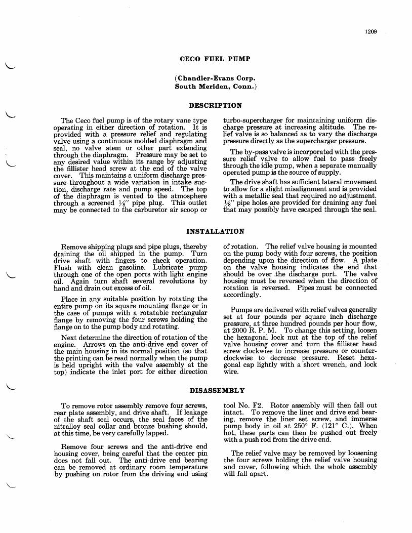
t209
The Ceco fuel pump is of the rotary vane typeoneratine in either direction of rotation. It ispiovided- with a pressure relief and regulatingvalve using a continuous molded diaphragm andseal, no valve stem or other part extendingthrough the diaphragm. Pressure may be set toany desired value within its range by adjustingthe fillister head screw at the end of the valvecover. This maintains a uniform discharge pres-sure throughout a wide variation in intake suc-tion, discharge rate and pump speed. The topof the diaphragm is vented to the atmospherethrough a screened L/a" pipe plug. This outletmay be connected to the carburetor air scoop or
CECO FUEL PUMP
(Chandler-Evans Corp.South Merlden, Conn.)
DESCRIPTION
INSTALLATION
DISASSEMBLY
turbo-supercharger for maintaining uniform dis-charge pressmre at increasing altitude. The re-lief valve is so balanced as to vary the dischargepressure directly as the supercharger pressure.
The by-pass valve is incorporated with the pres-sure relief valve to allow fuel to pass freelythrough the idle pump, when a separate manuallyoperated pump is the source of supply.
The drive shaft has sufficient lateral movementto allow for a slight misalignment and is provided$rith a metallic seal that required no adjustment.L/s" pipe holes are provided for draining any fuelthat may possibly have escaped through the seal.
Remove shipping plugs and pipe plugs, therebydraining the oil shipped in the pump. Turndrive shaft with fingers to check operation.Flush with clean gasoline. Lubricate pumpthrough one of the open ports with light engineoil. Again turn shaft several revolutions byhand and drain out excess of oil.
Place in any suitable position by rotating theentire pump on its square mounting flange or inthe case of pumps with a rotatable rectangularflange by removing the four screws holding theflange on to the pump body and rotating.
Next determine the direction of rotation of theengine. Arrows on the anti-drive end cover ofthe main housing in its normal position (so thatthe printing can be read normally when the pur4pis held upright with the valve assembly at thetop) indicate the inlet port for either direction
of rotation. The relief valve housing is mountedon the pump body with four screws, the positiondepending upon the direction of flow. A plateon the valve housing indicates the end thatshould be over .the discharge port. The valvehousing must be reversed when the direction ofrotation is reversed. Pipes must be connectedaccordingly.
Pumps are delivered with relief valves generallyset at four pounds per square inch dischargepressure, at three hundred pounds per hour flow,at 2000 R. P. M. To change this setting, loosenthe hexagonal lock nut at the top of the reliefvalve housing cover and turn the fillister headscrew ciockwise to increase pressure or counter-clockwise to decrease pressure. Reset hexa-gonal cap lightly with a short wrench, and lockwrre.
To remove rotor assembly remove fout screws,rear plate assembly, and drive shaft. If leakageof the shaft seal occurs, the seal faces of thenitralloy seal collar and bronze bushing should,at this time, be very carefully lapped.
Remove four screws and the anti-drive endhousing cover, being careful that the center pindoes not fall out. The anti-drive end bearingcan be removed at ordinary room temperatureby pushing on rotor from the driving end using
tool No. F2. Rotor assembly will then fall outintact. To remove the liner and drive end bear-irg, remove the liner set screw, and immersepump body in oil at 250o F. (12L' C.). Whenhot, these parts can then be pushed out freelywith a push rod from the drive end.
The relief valve may be removed by looseningthe four screws holding the relief valve housingand cover, following which the whole assemblywill fall apart.
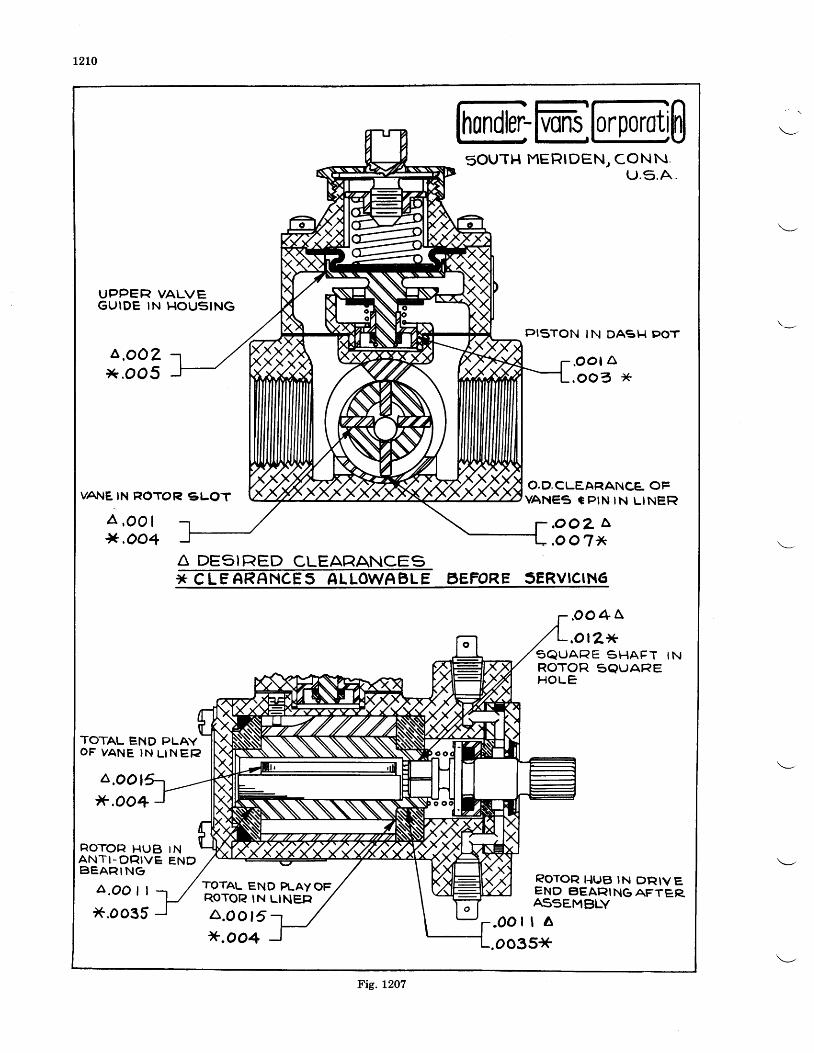
L?LO
SouTH MERIDENT CONNu.5 .A .
UPPER VALVEGUIDE IN HOUSING
PISTON IN DASH POT
a,oozx.oo5 .oot a
,oo3 ,+
VANE IN ROTOR gLOTO.D,CLEAF|ANCE OFVANES E PIN IN L INER
a , o o l*,oo1
.oo2 L,oo7 / \
X C LE ARANCES ALLOWABLE aEFORE SERVICING
. oo4a,ol2)+
S Q U A R E S H A F T t NROTOR SQUAREH O L E
TOTAL END PLAYOF YANE IN L INEF?
a.oo l)+,oo+
ROTOFI HUB INANTI -O t r I IVE ENDBEAFI ING
A.OO | |
*.o035
TOTAL END R-AY OFROTOT? I.IUB IN DRIVEEND eIEARING AFTERAS5EMBLYRoTOR lN LINg;1
A.o o15x.oo4
A DESIRED CLEARANCES
Fig. L2O7
LzLLCDCO FUEL PUMP
ASSDMBLY
Clean all parts carefully in gasoline. Immersepump body in oil at 250' F. (121' C.). Insertdrive end bearing by holding it on a tapered woodplug. Reheat if necessary, then insert liner insimilar manner, using a r/e" pin to line up theliner groove with the set screw hole. After cool-ing, install the liner set screw and its gasket, andinsert the complete rotor assembly. Then placeanti-drive end bearing carefully into pump body,and press squarely in place with an arbor presn.Do not heat when installing this bearing. Re-place gasket and cover and draw down four screwsuniformly.
Next assemble the shaft and seal parts in driveend of pump that are held in place by four screws.Tighten screws uniformly and check for freedomof rotation of the pump mechanisrn. If free,
INSPECTION ANI)
Fig. No. 1207 shows cross-sectional views of thepump. Clearances should be checked as shownfor both desired values and those maximumvalues above which parts should be replaced.Special attention should be paid to see that thebore of the liner is smooth, also that the workingsurfaces of the vanes are smooth and that themetallic drive shaft seals are carefully lapped.The square end of the drive shaft and its matingsquare hole in the rotor should not be worn ex-
stake the four screws in place. Assemble therelief valve in the valve housing, being sure thatit rests squarely on the valve seat and that itworks freely. Assemble the other parts of thevalve, such as diaphragm, spring and springfollower; and replace the valve housing on thepump body in the proper position, dependingupon the direction of rotation, with the fourscrews. Tighten uniformly. The lock wiringof all screws and the hexagonal lock nut shouldnot be done until after the pump has been checkedand the pressure regulated.
It is recommended that all gaskets and rubbersubstitute packings be replaced with new ones.
On pipe threads use only an approved pipesealing compound.
MAINTENANCE
cessively. When assembled, the pump shouldturn freely and show no sign of binding.
The diaphragm should be carefully checked tosee that there are no cracks or breaks, and thatit is very flexible. The valve shall fit freely in thevalve housing. The valve seat shall have aclean square edge all around, and may be checkedwith Prussian blue to insure proper seating ofthe valve.
1301
CHAPTER XIII
INSTRUCTIONS FOR STROMBERG NA.RgA AND NA-RgB CARBURETORS
OVERHAUL-NA.R9A
I)lsassembly-The carburetor should be dis-assembled for cleaning and inspection each timethe engine is given an overhaul. After thecarburetor has been removed from the engineand the hot spot and air intake or heater takenoff, the halves of the carburetor may be separatedbv the removal of the fillister head screws att[e parting surface and the venturi set screw.The
-economizer needle, mixture control needle,
Dump sleeve and venturi are held in the throttlebodv. The pump sleeve should be slipped off theoperating stem as soon as the halves are separatedas it is a brass stamping and is easily bent ifallowed to drop on the floor or bench. If it isnecessary to remove the venturi, it will haveto be driven out using a wooden plug similar tothat shown in Fig. 1301-.{. AU parts in thebodies, with the possible exception of the idledischarge jet assemblies, should be removed toenable a thorough cleaning and inspection.
Cleanlng and Inspectlon-The bodies andall parts should be thoroughly cleaned in gaso-line, and all passages blown out with compressedair. All variable parts should be checked tosee that their sizes are in accordance with thelatest carburetor specification sheet for the en-gine. Inspect all moving parts to see that theyiio not have excessive clearance.
Replacements-When ordering replacementparts it is necessary to give complete informa-iion concerning the parts desired to avoid delayin shipment or the receipt of wrong parts.Wherever possible, the serial number of the car-buretor should be given. A careful reference tothe attached assembly drawing (see Fig. 1302) todetermine the correct part number and name,and if marked with an asterisk ( *) giving the sizeas stamped on the piece, will greatly facilitateservice. A specification sheet giving the sizes ofiets, fuel level, economizer setting, etc., will be-furnished
no charge if you will write to the BendixProducts Corporation, Stromberg CarburetorDivision, South Bend, Indiana, advising themodel of your engine. Parts Price lists will alsobe furnished on request. P-t9223 covers acomplete set of gaskets for this model.
Reassembly-All headless screw plugs belowthe fuel level should be assembled with shellac,being careful not to get it on the end of theplug where it will come off and be carried bythe gas into one of the metering orifices. Head-less screw plugs above the fuel level and all otherthreaded parts screwed into the bodies shouldhave a compound of graphite and castor oil puton the threads.
When it is necessary to replace the throttleshaft, pump lever or throttle stop, assemble theIever and stop as shown in Figure 1301-8 and D.The throttle valve should be so fitted that itexcludes practically all tight when in the closedposition.
It is recommended that in replacing a floatneedle valve or a needle valve seat that thesetwo assemblies be replaced at the same time,as it is very difficult to fit a new needle to anold seat or a new seat to an old needle. The floatlevel should be fu" below the parting surfaceand is dependent upon the thickness of the gas-ket under the needle valve seat. The level shouldbe checked under the conditions encountered inservice as regards the fuel used and the fuel pres-sure or head at the carburetor. Those carburet-ors having a Yro" needle seat or gravity type,which is that one used with a gravity feed sys-tem having less than a9'1" fuel head, should havethe level set using 1 tb. pressure (39" gasoline.71-0 sp. gr.) at the carburetor. Those carburetorshaving a .L96" needle seat or pressure type,which is that one used with a gravity feed sys-tem having more than a 97 " fuel head or a fuelpump, should have the level set using 3 lbs. pres-sure (117" gasoline at .7I0 sp. gr.). If after assem-bling, the level is not correct, remove the needlevalve seat and put in thicker gaskets to lowerthe level and thinner gaskets to raise it. Achange in gasket thickness of t4ntt wrll changethe level approximately s/a".
When any parts of the mixture control sys-tem are replaced, care should be taken to seethat they are assembled correctly. As previouslyexplained the needle valve is operated by aneccentric pin which is a part of the mixture con-trol stem assembly. The mixture control stopis pinned to this same stem and it is importantthat the stop be located on it at the proper anglewith the eccentric pin. This may be done byplacing the mixture control stem, without thestem nut, spring and packing, in the throttlevalve body with the eccentric pin away fromthe pump mechanism and turning it until thedistance from the parting flange surface to thepin is Yra" (see Fig. 130L-E). With the stem heldin this position, place the mixture control stopagainst the shoulder of the stem with the stopagainst the stop in the body (full rich position)and drill through the stop and stem. Then as-semble the spring, packing, and nut on the stem,press the stop on against the nut, and pin inplace.
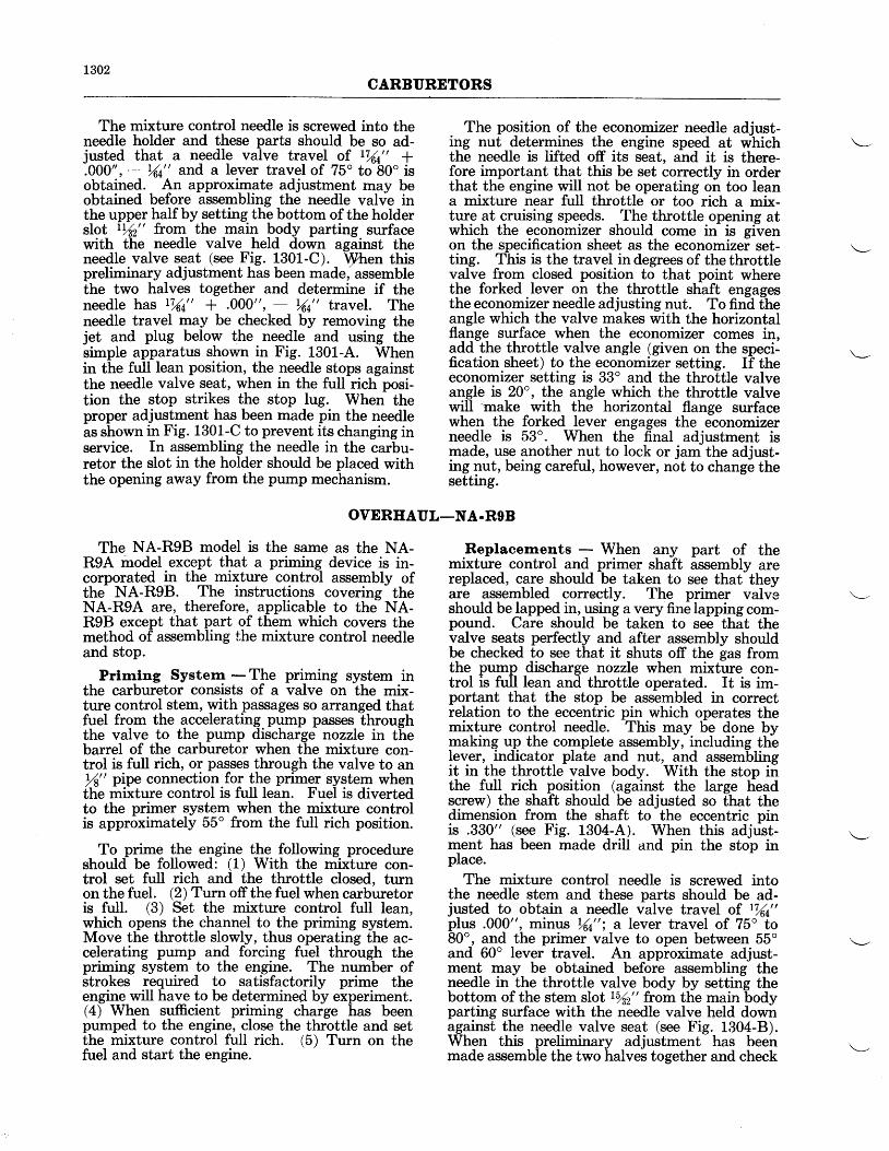
t302CARBURETORS
The mixture control needle is screwed into theneedle holder and these parts should be so ad-justed that a needle valve travel of r%t" +.000", - rAt" and a lever travel of 75o to 80o isobtained. An approximate adjustment may beobtained before assembling the needle valve inthe upper half by setting the bottom of the holderslot LrAz" from the main body parting surfacewith the needle valve held down against theneedle valve seat (see Fig. 1301-C). \)Zhen thispreliminary adjustment has been made, assemblethe two halves together and determine if theneedle has r%a,, + .000,,, _ |(t,, travel. Theneedle travel may be checked by removing thejet and plug below the needle and using thesimple apparatus shown in Fig. 1301-4. Whenin the full lean position, the needle stops againstthe needle valve seat, when in the full rich posi-tion the stop strikes the stop lug. When theproper adjustment has been made pin the needleas shown in Fig. 1301-C to prevent its changing inservice. In assembling the needle in the carbu-retor the slot in the holder should be placed withthe opening away from the pump mechanism.
The position of the economizer needle adjust-ing nut determines the engine speed at whichthe needle is lifted off its seat, and it is there-fore important that this be set correctly in orderthat the engine will not be operating on too leana mixture near full throttle or too rich a mix-ture at cruising speeds. The throttle opening atwhich the economizer should come in is givenon the specification sheet as the economizer set-ting. This is the travel in degrees of the throttlevalve from closed position to that point wherethe forked lever on the throttle shaft engagesthe economizer needle adjusting nut. To find theangle which the valve makes with the horizontalflange surface when the economizer comes in,add the throttle valve angle (given on the speci-fication sheet) to the economizer setting. If theeconomizer setting is 33' and the throttle valveangle is 20o, the angle which the throttle valvewill 'rnake with the horizontal flange surfacewhen the forked lever engages the economizerneedle is 53o. When the final adjustment ismade, use another nut to lock or jam the adjust-ing nut, being careful, however, not to change thesetting.
OVERIIAUL-NA.R9B
The NA-R9B model is the same as the NA-RgA model except that a priming device is in-corporated in the mixture control assembly ofthe NA-R9B. The instructions coverins
- the
NA-R9A are, therefore, applicable to tht NA-RgB except that part of them which covers themethod of assembling the mixture control needleand stop.
Prlmlng Systern - The priming system inthe carburetor consists of a valve on the mix-ture control stem, with passages so arranged thatfuel from the accelerating pump passes throughthe valve to the pump discharge nozzle in thebarrel of the carburetor when the mixture con-trol is full rich, or passes through the valve to anrA" pipe connection for the primer system whenthe mixture control is full lean. Fuel is divertedto the primer system when the mixture controlis approximately 55o from the full rich position.
To prime the engine the following procedureshould be followed: (1) With the mixture con-trol set full rich and the throttle closed, turnon the fuel. (2) Turn off the fuel when carburetoris full. (3) Set the mixture control full lean,which opens the channel to the priming system.Move the throttle slowly, thus operating the ac-celerating pump and forcing fuel through thepriming system to the engine. The number ofstrokes required to satisfactorily prime theengine will have to be determined by experiment.(4) When sufficient priming charge has beenpumped to the engine, close the throttle and setthe mixture control full rich. (5) Turn on thefuel and start the engine.
Replacernents - When any part of themixture control and primer shaft assembly arereplaced, c,ale should be taken to see that theyare assembled correctly. The primer valv-eshould be lapped in, using a very fine lapping com-pound. Care should be taken to see that thevalve seats perfectly and after assembly shouldbe checked to see that it shuts off the gas fromthe pump discharge nozzle when mixture con-trol is full lean and throttle operated. It is im-portant that the stop be assembled in correctrelation to the eccentric pin which operates themixture control needle. This may be done bymaking up the complete assembly, including thelever, indicator plate and nut, and assemblingit in the throttle valve body. With the stop inthe full rich position (against the large headscrew) the shaft should be adjusted so that thedimension from the shaft to the eccentric pinis .330" (see Fig. 1304-A). When this adjust-ment has been made drill and pin the stop inplace.
The mixture control needle is screwed intothe needle stem and these parts should be ad-justed to obtain a needle valve travel of r%t"plus .000", minus rAE"; a lever travel of 75o to80o, and the primer valve to open between 55oand 60o lever travel. An approximate adjust-ment may be obtained before assembling theneedle in the throttle valve body by setting thebottom of the stem slot r%2" from the main bodyparting surface with the needle valve held downagainst the needle valve seat (see Fig. 1304-8).When this preliminary adjustment has beenmade assemble the two halves together and check
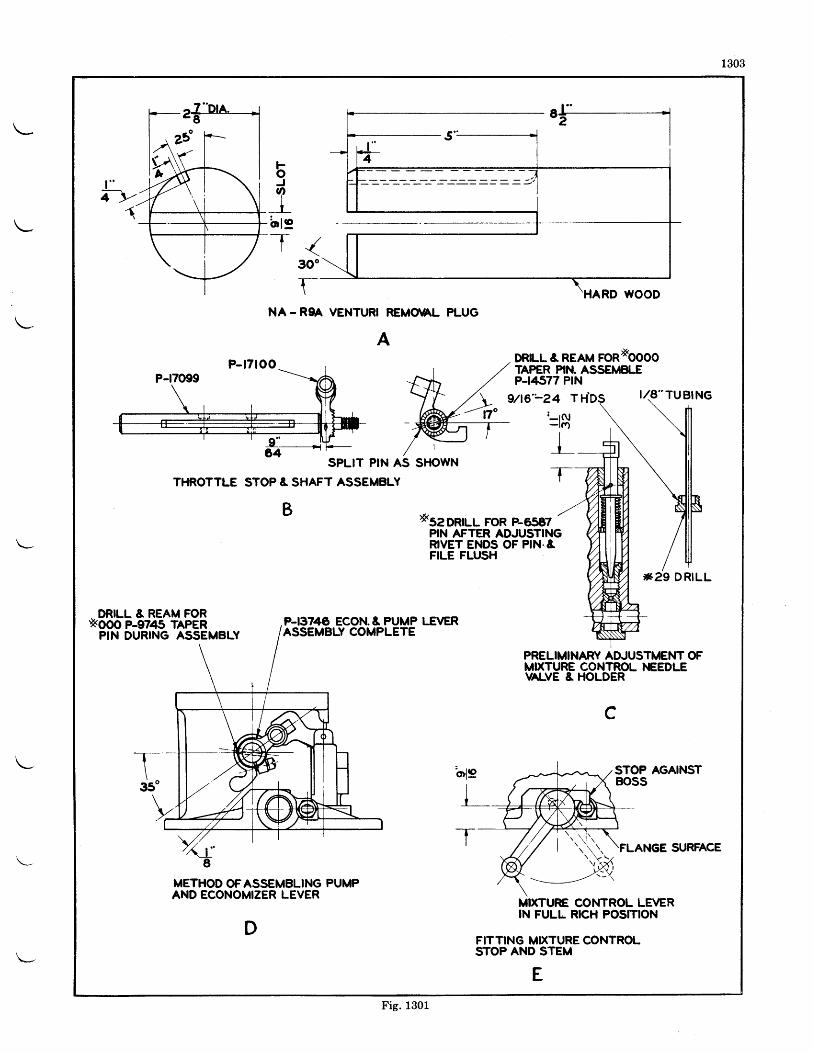
1303
t "T-\-
F.oJvl
It
bte-TI
1
NA - RgA VENTURI REMO\AL PLUG
ADR[.L & REAM FORXOOOOTAPER PIN. ASSEMBI.EP-t4577 PtN
SPLIT PIN AS
THROTTLE STOP & SHAFT ASSEMBLY
9/a6'-24 Tt- tN
_ _t(f)
It
-t-- -
B xseonuL FoR F65E7PIN AFTER ADJUSTINGRIVET ENDS OF PIN"&FILE FLUSTI
DRILL & REAM FORx.ooo P-9745 TAPER
PIN DURING ASSEMBLYP-I3746 ECON. & PUMP LE1YERASSEMBLY COMPLETE
PRELIMINARY ADJUSTMENT OFMIXTURE CONTROL }€EDLEVAT-VE & HOLDER
c
T350
ol9
II
-t- -
STOP AGAINSTBOSS
SURFACE8
METHOD OFASSEMBLING PUMPAND ECONOMIZER LEVER
DMIXTURE CONTROL LEVERIN FULL RICH POSITION
FITTING MIXTURE CONTROLSTOP AND STEM
E
P-t7too
]*29 D RILL
Fig. 1301
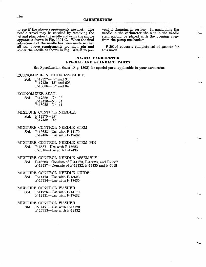
1304CARBURETORS
to see if the above requirements are met. Theneedle travel may be checked by removing thejet and plug below the needle and using the simpleapparatus shown in Fig. 1304-C. When the finaladjustment of the needle has been made so thatall the above requirements are met, pin andsolder the needle as shown in Fig. 1304-B to pre-
vent it changing in service.needle in the carburetor thestem should be placed withfrom the pump mechanism.
P-20L46 covers a completethis model.
In assembling theslot in the needlethe opening away
set of gaskets for
NA.ROA CARBURETORSPECIAL AND STANDARD PARTS
See Specification Sheet (Fig. 1302) for special parts applicable to your carburetor.
ECONOMIZER NEEDLE ASSEMBLY:Std. P-L7321- 5o and 34o
P-17430-L5o and 60oP-18036- 2o and 34"
ECONOMIZER SEAT:Std. P-17328-No.
P-17436-No.P-I.8028-No.
MIXTURE CONTROL NEEDLE:std. P-L4L70-L5'
P-L7432-30"
MIXTURE CONTROL NEEDLE STEM:Std. P-15623-Use with P-14L70
P-17 435-Use with P -t7 432
MIXTURE CONTROL NEEDLE STEM PIN:Std. P-6587-Use with P-15623
P-7018-Use with P -17 435
MIXTURE CONTROL NEEDLE ASSEMBLY:Std. P-16283-Consists of P-14170, P-15623, and P-6587
P-L74}7-Consists of P-L7432, P-L7435 and P-7018
MIXTURE CONTROL NEEDLE GUIDE:Std. P-t4L7}-Use with P-15623
P -t7 434-Use with P-L7 435
MIXTURE CONTROL WASHER:Std. P-LL726-Vse with P-14170
P-17431-Use with P -L7 432
MIXTURE CONTROL WASHER:Std. P-1417t-Use with P-L4L70
P-L7 433-Use with P-I7 432
323444
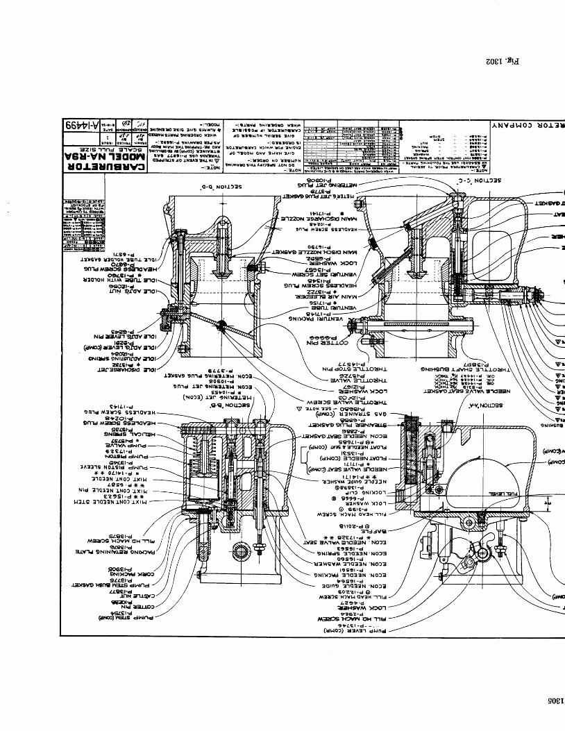
-: l . l t td INIIZOIO X?lU\l . le rstod .rt tortrnttvtJO LatHnX ' lYt l ts
t^t9
- : ( | t t t o l o t ll ioJ,t tnatvf r{t tHM lo! lNtgx?
JO ' l tool, , l ONV tLrVN tAlD
-: l?qto No l?t lulnN9ral/vrvlO Sll{J Atlft.ls .lON O€
-:tJ,oN
=|Z|S 'l'rnJ 3]vts
u-vN 1300nuotSunEuvs -:9l lvd ?i lAoaroi l tsft ln l?Ogts ax
avrlrg o.l lonr :tour*tl? I-: t IgN
P erol 33s.- O'gget.d(dno, u3NtYUJ.s SYC
z0gilEI.{
ANVdr, . toJ uor3 l l
NOlf2SS
.v-v.r.rorJrEs
Vu9NlHSnS I
(avprN
(ctt€
l o l sHtrl
lnN
9 i r r )Y l?Nrus
nitva
rLs9 -dIr)rsYE 13010H tBnr
o-Q NOu.)3S
6 4 a e - dt3ysv9 9n1J 9xtttrrl,l .ito2l
9 0 5 0 1 - d9n'rC I3n 9Nlllltt^l 'NO?t
SS lg t ' e l *(No:a) r:c ?Nrtaral,.l
.,c.€"NouJ-s
go60t-dglTrd r3f 9Ntt:Ftil
6.LLEIr$rwg grTrd J5f '9p3L3r.t
t ' tL r -d *g'lzbfrl 39:|YH)SE! NlVlA.
3 ' ? 0 1 - d9n1d l^et:s s8t'loveH
0 6 4 9 r - dl;lxsvo lnzzoN'H)s,cr Nrwl
zc39-d-a3HSV A X301Lgi9er4
,vr=rat)s .r-=ts r?,nJ.NEnglc! l
gn'rd Ma?rtsZZLet-e I
"r!t(Er=n€ etl\r/ NlVt lgslAl-d rt3€nr ranlNSA
9 ' | r r -d9Nlylvd tunlN3n
9999-dN|d
L L s r t - d 'Ntd dors 3-ll'J.oeiHJ"
9ZLCre=A''rvn 31lJ.odtu-
zgtzt-da3H€i\/ir\ >{)o1eO;Zt 'J
M3a)s Sn.rvn =1lJo3HL
ggs9'da-vsvg9n1J e3r
4€ltEl.d *E^'lyn dhrndc ? € L l - di.to'tStd dhtnd
6rLet-a3A3?1S Notstd dNnd
* { ( o l ' l t l -d r3'lo33N 'J,N0?
.txl l,,lL9S9 .cJ t( t(
N td 3101?N INOS J .X | I . I€ ? 9 S r - d x *
hlJ.s 3'1033N .r.No) J,XIN
oL99-d90'ld,uEratJgt SSi|.|(l VaH
c,|,4ct-d *u3q'roH HJ.trv\ -gt1l 3.tor
99,q;zt-dlnN '9.fov
l1o
euz?-e /Nrd l3^;n qmv 31ol
1r.or1 ..rl$ girlor
;.:rl,?9('?,t-d
o|\ilius 9N[9nrtvzerci'g *
L3fSgvHrs,o
C ' l l r - dI n'rd,v\3u?s sB3'10Y3 l{
a+zot.d9nrd /\,l3a|'s sg3'rO\GlH
9eLEt-agNEtdS 'tv?l'tirH
9OGClrd'9Nrytw y30t
LLlrct-aJ]N iru,EY
€€:DlrJNtd I;u10,
tslQ,t'd(ar$)rGus dhrnd
9882-dlitvsv9 -L\Gls =rKl33N 'No23
s B 9 l t - d @ x- (dr{o)) t!:rs ? z'lg3aN tyo'rJa
lc"nvr) "*,iil'i-'j* ^"" ''
| | (ahrof,) 3]o33Nlvo1l5 t l l t r - d *
(ano:) tvas sn1vn =rxte=r N
Szget-d / iM:|:tt€'H3vhr €H 'r.]LJ
i /
=r-r.v'rd u*,n?El"u*n r/ l,/l
gOGCl.c, ,/ I
t L t r t - d { ( r (?3HSYM Sdrno 3'1033N
@ 9 6 9 c 1 - ddr.t f oNr)|20'1
@ 9999-du3t {svM ) :o1
@ eete-aM?U2S r{fvl.l OYEH '1'llJ
€ i l0?-d @31J3Vt l
* x e?Eet -d i(rvss 3A1YA 31033N 'NO?3
€ 9 S 9 t - d!NruJs 3'1(133N'NO)3
o9s9t -dIJ3HSV/\ ?'1s33N'NO23
l 9 S 9 t - d9Nl)2Vd 31Ct3EN
' 9 5 9 t - d30rn9 31q3lN
6 0 ? ? t - d @/r\3:l?S H)Yt l CIV:IH '-1'1lJ
L Z g t - dairH9YlA )t3qt
tzez-a/Yr=lzDSlf2vl^| oH'TilJ
9 l t c t . d ^ - . . .('dr.lo:) rra^3'r dlrnd
9LLeraJ.iDrsY9'|€O€'1t=lt.S drdnd
' N O ) 3
' N O ) 3
908I
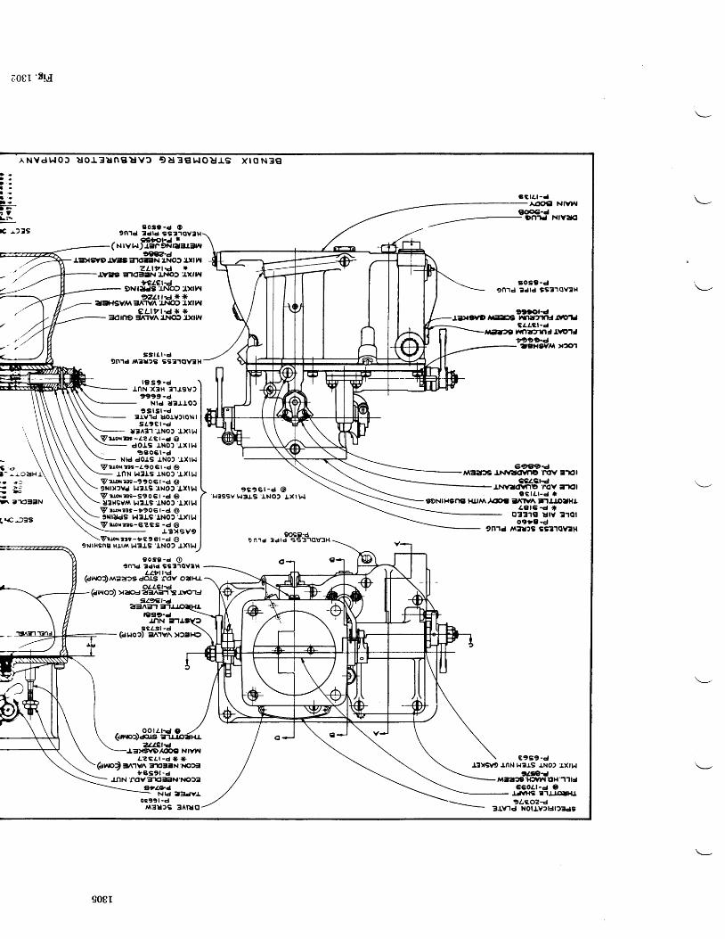
e08I ' t I . {
^ N v d h t 0 J u o l 3 u n g u v f , 9 a 3 € L . t o u l s x t o N 3 eD -D .D ' rl ot :3 <t -I F. fLF
E r2 lS
cci l . t-d-AOOE| NIVNIg6ci-d
Dn'rd Nrvao
et -
&-drE|xw9 ty=13 ErKllilN 'r,Not aI| Fl
zLt? t -a Il\nl3 gt<EttN LNo) '4xr1^f
utr,ff6ti$t t",tn.*r"r =,ffii''lHdtr,^
et-rtr-d * *=1(t no =t^'rv^ LNo) .:rxrw
SSlt t .c ign'rd l^tr?s ss310v:lH
r 9 s 9 - dJ.nN x3H 31tSVl
9999-dNId UEJ. IOJ
9 S l S r - d3rvld lJOtYlloNl
s L 9 E r - dU3431 J.No) :lxlt^l
Vru,o{7ir -Z?ZEt-d @dol,g tNo)'Jxrhl
99061-dNrd dors INol 'lxrr,,l
V " r o N r t r - t 9 0 6 t - d @rnN HllS J'NOI'J,XlN
Vrr! | |r$-9906t-d O9NrX2Vd !1319 tNOf IXlt^lV i lo r r rs -Sgo6t -d OU3|{SV,Y\ l.l3IS'lNOf 'tXt t"l
p rronns-i9o6t-d @9illudS t^l3lS'INOt'lxl t"l
peorzes-6?Es -d @J-3xsv9
Vrl .xr r i - tg9st -d @9NrHSng Htrr\ W3J,S
'INO? J.XtW
9 s 9 6 r - d @r.,r3ssv t{3ts 'tNo2 txlw
909C-d9n.ld 3dld SS3']C!U3H
9 0 s 9 - c O9n1d tdrd ss]rov3t{
- atfrt-J *(NlVl^r)r3F9n |aer3w
9 o s 9 - d O9n1d tdrd st3.roYtH
LLttra(dhro')/v\aa)s do.rs r(lv oeHr
044€l:d(dwo") va|oJ e:rner l3 rrc13
30s9-d9n1d Sdrd ss?10v3H
tttol'dx:r|fs rrSriut'tftl.&ulJ
cr.tcl-dtmlynJlrolJigt9.d'zttHev/l x51
G?f,qD4MSets Inn,ilKlvno 'rcV ;l-tol
ce4€t.dlN\ft|(llfrE ',.ov -rl(ll
S C l t l - d r tsENr HSng Hlrl^ .^(pc Elflv^ inlolHr.
ee t6-d J r0331€ UtY l10l
o9|9.d9n1d ,v1?!2S SS':|1AV:H
€ 9 S 9 - dl,3vsvg rnN H3J.s rNo, J.xtt.l
tilfr:dM3:t"3 't{'vr t EH -l'ltJ
660r.1-d ol,Jvlrli a.lJ.LGltt{l?Lf.oz4
' a a a- ) J- l o!
l\ 3E3.N
Lr€.J3S
(a, to) anvl\ =rE3aNl€)3' B s 9 t . d
9Z9Ct-ea3n=n e'l
r399-dlnN -n
S c a s l - d \(aHoc) =l^'rv^ x)rlda
o o l(ann:)aos
zLlet€'l3v€itlDl.lc,€ NrvhlL?€t l -d JF *
.tnN rov:rt'=GrN't{o)tetla?l
Nrd z3dvL0r991 -d
r.Jr3u)s 3^lt|o
d
^ i o a H f
908I
3IV1d NOlIY2rJr23ds
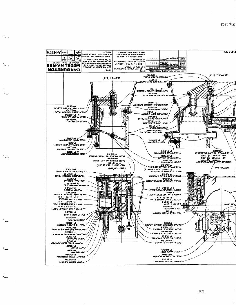
- ?6str-d gNt/{VtO tu svfflo. tarvta tt{J,oir|.ar,l-t! qtv
9r.r'rirro-tt Ar (aHo) rrrtytrisYO 4attt-d lsn s(Mllt{J.o:rddltls ao INIA?tlu.ril \y
- ' l roN
-: l r lYd tNrrt( l lo N?Hf^t 'r trssod rr loJ.StnttvtJaO ltrat. lnx 'rYtl ls ZAl9
- : o t t t € l o s lrorl t |nt lvc Hf lr l rs !o! tNr9x?
ro . l tQo t r oNV 3 t tYN lA rD
-; l t?qlo No l tgLlnNtNrrAVl<! s[{J, Al|ltde IoN OO
_: t J ,oN
=zrs'] ']nJ 3-]v?s6U-VN 130D1
uolSunguut
808r 'E Id
ANVdt . I
rAs9 -d
oaAcf-d rLressv -xlfll,
g€OZt-dJnN 9r€V
c) r l r -d9ntt fi13u2s Bslnov3t{
Srzot€9md,rlEFS s9E11lV?H
*tl,tse9i.g4i'rv?rEsr
4Et€hd *eA'lVil\d^rf'td€ " G a r - dFE&sld dAnd
6fi4.€l'd't^t3ssv tsA3ars dhlnd* * 0e l9 r -d t r?1q?3N J.ilO? .lxtbr
* * Lg39 -dNrd 31013N.il*o? .J.xt 1..
* * € " r s l - J1",l3rs 31033i( rilO) rxtt.l
c9?€l-dXral.l l.lrJ'S Ctlfld
196€l-drallgvi\)|201
sz8€r-d/VGTJfIS H:'VhI AHTIIJ
9€elrdEt-w'td 9NtNtvt ltt 9Noaf,lH
caecl-dr3HSYlA 9xrxtvrAl| .l{t)Ovd
li6ehEqrrlXwJ XtOt92LEt-4
.r3)lsv9't{3llE }vals dl.|nd4fl€€
JrN Tust(EDI€
Nld rElr r'rCOtZGr-d
9NlHSng lrEJJS dr^lnd9LZGI-d
't"l3SBY WAIS dhlncl
?gnr
c-q Notl)?s
6 A A C - dtlillsvD gnid txrSartu|xo23
e060t -d9n1d r3n 9r|l|:LLtht .Notl
ss )01 .d r('Ho:r) t?c eNtu3r?t.l
.€-{1. t{ouJ:ls
I t r l / . l -d le]ail 39affHf,g'El Nlv^l
e t ? o l - d9n1d A^ta2s tsnqv?H
ose9r -dI:t)tsvo lnaN'Htsrcl xrvl
2&t?-d-aaHS/Y\ >|3O1L9l9€|-4Its r.=ts lijalrNSn
Zzl-et'd Ieirlgln€ ?ilv Ntvr^l
gslet-d |r
NOU,?19
.FV.NO[2ilS
3€nr rafrrNt^9 ' ra r -d
9Nrylvd lunlNtn
99994t\ld
@wt'dMEa)6 E,A'rVn =rUl.oeHJ
98A?-d.t\GB =ndaEN }{Or3
{( rF g?rtr-d r1V3S :lfW
3.lOEGtN r{O)3l I l t l -d i t
'].|3SSV -l.�3S irn1v^ StlEFN) F * l t t ? l - d
z3HSYM 3d1n0 t1033Nc69€l -d
dr1) gNlyro ' l
f,999-du?r{EYM Xf O1
50r -d,S?U'S H)Yl , , l OY3H'u l l
ESE|rd3A1VA;r1(l:t3N .LWIJ
€9S91 :€JgNnadB 3' lottN'xo23o'ts9l -d
UlHSY,I\ 31OBBN 'NO?l
1 9 S g t - d9 N l v f \ € 3 1 Q 3 3 N ' N O f 3
t t9g9l -d30tn9 31q33N'NOfe
ggm4tGtfl- rtA )arflezr-d
,|l;EGTffn| ([{'TIH9 '1C,1-d't,lSSSV it*\-s'l dHnd
V "l.ox 3"s - og9€t -d' ! .tassv u3NrYUJ.s Sve
9S€9'dJ.iDtSY9 9r'l1d ?l:tNtY?lJ€
eri294 /Nk aE 3'r9mVtlol
vn)a-at sssv dans.l qltv lrrtl
"@2H9N0ds eNusftrw irtl
*Lotsf'*,*^G
LLsUt -d 'Ntd dorg a-lr.ioaHl
-/ NU \ \\N \ \ \ I
\ \ \4'Bcri.o**\'-Hffij?#t--'\
JitxsvgrvE s 3 'rvA irtctEtN \
gzLerd€t^'rvn =rluo?tF{r
908I
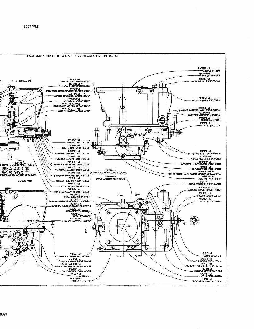
-,
e0gl 'EI"i{
AxVd l . lOJ Uo l3ungEv f , 9U3C| I ^ IOUIS X loN?g
xOr1219 30s9 -ctn' ld 3drd sst. lovSt{
- €Eil€rJ *( N I v t^t) JEIF 9f.{|a!11!il4,
eg''u�-d^ar$lo rt:rs :rr(EGrN ].Nof Lill^l
z L t t t - e *rvl3 in<El3 r LNOt'fxrw
ur,S6t'l#o" "t,^* * 2L t1-a
ati*{SVrv\ 3A'rYn'rr\|of J.Xl 3^l* * e L t r r - d
3dn9:tflv^J}{q? l)(|t l
t t r?Gl -Gl
dOl,S'!l'lo) 'l.xtlr
aasfr -d
t.|ld dOIS l,ilO] J.Xttlt66St -d
U]ll{Svrt l'JYHs'lNOl'Ixll.l'szter -d
,ilHsfig lJ\il{s l.No)'rxl!.|??98r -d
9xtHsnel'tilo) J.xt!.Is?9€r -d
99€'(tl"d.r:Dtgv9 ffilal)9 nnntfiJ trtrlJ
6 b ? € l - dAOC}CI NIVW
f|€€€-clj On.|cJ NIYaO
ss tLr -d9n1d nirDs ss31qv3H
sose-den.rd Sdrd ss?1ov?l{
c/,tcl-dWnU2rlnJl\tor1J,99'>-d
"tSHstvli x3cr19t99-d
\t.
r-68SFd \).trrtl l'-anf, 31rtol+1 J,
.rY.l€utiF
c f :r;Ii
,xr).)vc Ijvlls tilo) .lxll,lte9€l -Gl
ifilxsv^\ 9||l)rfvd'lt{o) lxt}r? 9 9 3 1 ' d
9r.rlds tJvr{s 'lNof rxll,.lttz6l -d
'L|3SSV 3A1YA'rNOt'txll^t9 b z 6 t - d
HSNS RI'IA IJYHS INO) IXII,{0 0 s ? - d
,f\t tdtd sst.lqvtHLLfrFA']{?SSv l aefg&J.s rov oaFu
04(€hd:l.f:rssv xaEJ ?fen-t !3 aroid
l€tslg.drnN 3-l
9ca9l -dLJ=ssv =l^']v^ xf3H9
o o r e r - d'l{3ssv &rssL?6r -d
Jr * &?€tr -d' r.l3ss v :t^.lvn :rEl3ilr\r'!{o)3
t '€s9 t -dInN'rov?rt :ErN'l{o?3
e?lCrd- Nrd llk;vloct? l -c
oEz6t -d'l,.l3SSV
IIVHS'INO2'tXl t^l
09 iB-d9md /|\t|l29 s
Nrd urrro2
oL9i -49n'rd l tir2s 9s31(tv3H
gosE-dtn.1d edld s€310\/eH
eacrq-4Maa36 J'tr&?r€VTrg'nOV 3'rOl
€ce€hdIi{v?toYflE 'fov:rKll
el{zz6l -d .*€DNtHgn€ Hl^^,^@tt EIAT,A =nlroaH.t
4g t5-d r io331il t lY 310t
s s l L t - d9n'rd,t\3rr2s SsSilov3l{
zztar-dAA:IA2S'H)Yr.r OYek 11tJ
sa9Er-dl,3^3'r 'r.NO) :lxrlJ
9 5 r S l - d3rv.ld torv2rqNl
4'4,\
F *, i iY
or. ' l al ts{-d lorj>.- tt lt.'tr-d loAD--q nlrr.< lFO.- I( artS-d
ffi, -v1rfi t^.rt^irtstE=lN
@
l f |s9-dJ.nN 3'llSY)
€1959-d,1^3d)S' l { )Y l i q \€H' l ' r t j
€ E e a t - dI?XS\r9 rnN L|3J,S rNO' J.Xlr,,l
913e4M3a"9'H3Yl l Ut{''l'llJ
6 6 0 a 1 - dr.JvHs e.r!o!t{r
lo9G -d
908r
M3Uf,G 3Atr!C 3-tv'rd Nolrv2r3r2rds
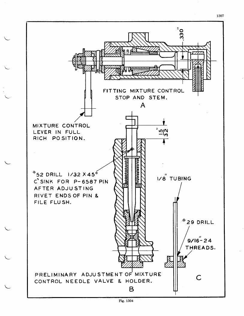
1307
- o(Yl
F I T T ING MIXTUR E CONT ROLS T O P A N D S T E M .
A
M I X T U R E C O N T R O LL E V E R I N F U L LR I C H P O S I T ] O N .
= .'rt\- r o-_
t
o s z D R T L L t / g z x 4 s " , ,I / 8 T U B I N Gc ' s r N K F o R P - 6 s 9 7 P t N
A F T E R A D J U S T I N GR I V E T E N D S O F P t N &F I L E F L U S H .
D R I L L
t ,
9/t6- 2 4T H R E A D S .
P R E L I M I N A R Y A D J U S T M E N TC O N T R O L N E E D L E V A L V E &
O F M I X T I J R ECH O L D E R .
BFig. 1304
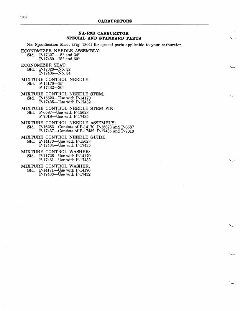
1308CARBURETORS
NA-ROB CARBURETORSPECIAL AND STANDARD PARTS
See Specification Sheet (Fig. 1304) for special parts applicable to your carburetor.ECONOMIZER NEEDLE ASSEMBLY:
Std. P-L7327- 5" and 34"P-17430-15o and 60o
ECONOMIZER SEAT:Std. P-t7328-No. 32
P-L1436-No. 34
MIXTURE CONTROL NEEDLE:std. P-14170-15"
P-L7432-30'
MIXTURE CONTROL NEEDLE STEM:Std. P-15623-Use with P-L4L70
P -L7 435-Use with P -L7 432
MIXTURE CONTROL NEEDLE STEM PIN:Std. P-6587-Use with P-15623
P-7018-Use with P -L7 435
MIXTURE CONTROL NEEDLE ASSEMBLY:Std. P-16283-Consists of P-14170, P-15623 and P-6587
P-L7437-Consists of P-17432, P-17435 and P-7018
MIXTURE CONTROL NEEDLE GUIDE:Std. P-14L73-Use with P-15623
P-L7 434-Use with P-L7 435
MIXTURE CONTROL WASHER:Std. P-7L726-Use with P-L4L70
P -L7 4}I-Use with P -L7 432
MIXTURE CONTROL WASHER:Std. P-L4L7L-tTse with P-L4L70
P -L7 433-Use with P -L7 432
INSTRUCTIONS FOR STROMBERG NA-RgCT ANI)
1309
NA.RgCz CARBURETORS
OVEREAUL
I)lsassembly-The carburetor should be dis-assembled for cleaning and inspection each timethe engine is given an overhaul. After thecarburetor has been removed from the engineand the hot spot and air intake or heater takenoff, the halves of the carburetor may be separatedby the removal of the hexagon nuts at the partingsurface, the venturi suction tube for theeconomizer and the venturi set screw. Theeconomizer needle, pump sleeve and venturi areheld in the throttle body. The pump sleeveshould be slipped off the operating stem as soonas the halves are separated as it is a brass stamp-ing and is easily damaged if allowed to drop onthe floor or bench. If it is necessary to removethe venturi, it may be necessary to use a woodenplug similar to that shown in Fig. 1307-A todrive it out. All parts in the bodies, with thepossible exception of the idle discharge jet as-iembly, should be removed to enable aih6roughcleaning and inspection.
The economizer needle and diaphragm maybe removed by removing the- nuts- holding theeconomizer cover to the throttle body.
The assembly containing the mixture controlplates and primer valve may be removed fromthe throttle body for a more complete disas-sembly. The automatic mixture control unitshould be overhauled in strict accordance withthe instructions issued on that unit.
Cleanlng and Inspeetlon-The bodies andall parts should be thoroughly cleaned in gaso-line, and all passages blown out with compressedair. Alt variable parts should be checked tosee that their sizes are in accordance with thelatest carburetor specification sheet for theengine. Inspect all moving parts to see thatthey do not have excessive clearance.
Replacements-When ordering replacementparts, it is necessary to give complete informationconcerning the parts desired to avoid delay inshipment or the receipt of wrong parts. When-ever possible, the serial number of the carburetorshould be given. A careful reference to theassembly drawing (Fig. 1309) to determinethe correct part number and name, and ifmarked with an asterisk (*) giving the size asstamped on the piece, will greatly facilitate ser-vice. A specification sheet giving the sizes ofjets, fuel level, economizer setting, etc., will befurnished if you write to the Bendix ProductsDivision of Bendix Aviation Corporation, SouthBend, Indiana, advising the model of your en-glne. Parts price lists will also be furnished onrequest. P-61307 covers a complete gasket setfor the NA-RgCl and P-61308 covers a gasketset for the NA-R9C2 carburetor.
Reassembly-All the headless screw plugsbelow the fuel level should be assembled withshellac, being careful not to get it on the endof the plug where it will come off and be carriedby the gas into one of the metering orifices.Headless screw plugs above the fuel level andall other threaded parts screwed into the bodiesshould have a compound of graphite and castoroil put on the threads.
When it is necessary to replace the throttleshaft, pump lever or the throttle stop, assemblethe lever and stop, as shown in Figures 1307-8 and1307-C. The throttle valve should be so fitted thatit excludes practically all light when in the closedposition.
It is recommended that in replacing a floatneedle valve, or a needle valve seat, that theseparts be replaced at the same time, as it is verydifficult to fit a new needle to an old seat or anew seat to an old needle. The float level shouldbe V4" below the parting surface and is dependentupon the thickness of the gasket under the needlevalve seat. The level should be checked underthe conditions encountered in service as regardsthe fuel used and the fuel pressure or head at thecarburetor. If, after assembling, the level is notcorrect, remove.the needle valve seat and put inthicker gaskets to lower the level and thinnergaskets to raise it. A change in gasket thicknessof Y64" will change the level approximately 5/a" .
When any parts of the mixture control coverassembly are to be replaced, the shaft and stopshould be assembled as shown in Fig. 1307-D.If the valve plates are to be replaced, they shouldbe lapped in with a very fine lapping compoundso that any possibility of air leakage wilt beeliminated.
The cruise valve stem and lever should beassembled as shown in Fig. 1-307-E.
Upon completion of the carburetor assembly,the economizer should be set to open at the valuespecified on the specification sheet. The venturisuction tube through the wall of the venturishould pe plugged ald t};re %" pipe plgg in -theecononuzer cover should be removed and asource of vacuum connected to this chamber.The small 10-32 plug in the economizer adjust-ment screw in the cover should be removed andan Ames Dial Gauge should be assembled sothe leg is resting against the economizer needlestem as shown in Fig. 1307-F. The vacuumshould be increased until the Ames dial indicatesthat the needle has started moving and that pointshould be taken as the opening point. NOTE:A water manometer should be connected to the10-32 manometer connection on the economizer
1310CARBURETORS
cover so the correct suction may be read in"inches of water". If the opening point is notas specified on the specification sheet the locknut on the adjustment screw should be loosenedand the necessary adjustments made.
It is essential that there are no leaks aroundthe gasket surface of the carburetor or aroundthe mixture control assembly, therefore, thecarburetor should be water-tested. Plates and
gaskets should be assembled to both flanges ofthe carburetor and 3 to 5 lbs./sq. in. air pressureapplied to the inside of the carburetor througha connection in one of the plates. NOTE: Donot exceed 6 lbs./sq. in. pre$sure as the floatmight be damaged. The carburetor should thenbe submerged in water and any leaks found andrepaired.
Safety wire the carburetor before installingon the engine.
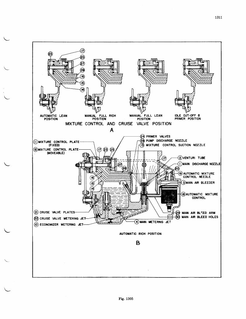
131 1
AUTOMATIC LEAN MANUA- FULL RICHPOSITION POSITON
MIXTURE CONTROL AND
A
MANUAL FULL LEAN IDLE CUT-OFF 8POS]TON PRIMER POSITION
CRUISE VALVE POSITION
MIXTURE OONTROL PLATE(FIXED)
PRIMER VALVESPUI'P DISCHARGE NOZZLETIXTURE CONTROL SUCTION NOZZLE
TURE CONTROL PLATE(MOVEABLE}
VENTURI TUBE
MAIN DISCHARGE
AUTOMATIC MIXTURECONTROL NEEDLE
AIR BLEEDER
@ cnurse vALvE PLATEs MAIN
MAIN
TOMATIC MIXTURECONTROL
AIR BL1ED ARMAIR BLEED HOLES
@ cnurse VALVE METERTNG JEMAN ilETERING .JET
@ econoMEER METERTNG
AUTOTATIC RICH POSITION
B
; N N - - -
Fig. 1305
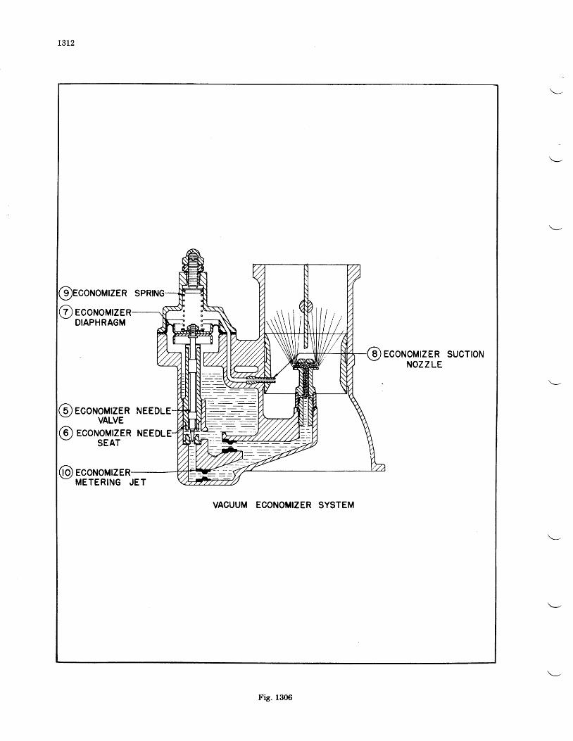
t3L2
ECONOMIZERNOZ Z LE
SUCTION
VACUUM ECONOMIZER SYSTEM
5 ) ECONOMIZER NEEDLE
METERING JET
9 )ECONOMIZER SP
@ econoMrzEDIAPHRAGM
ECONOMIZE
VALVE
Fig. 1306
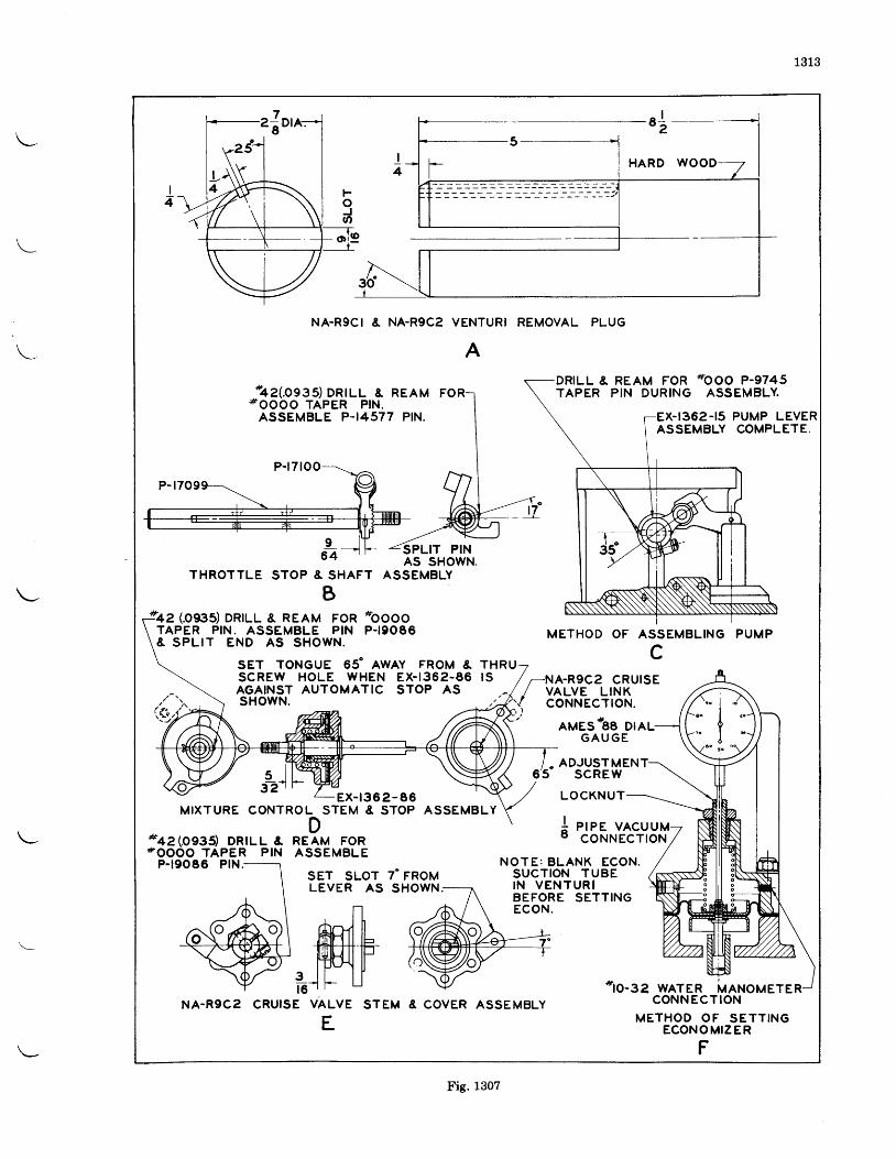
1313
\
NA.RgC I & NA.RgCz VENTURI REMOVAL PLUG
A
*4" (0935) DRILL & REAM FoR'fOOOO TAPER PIN.ASSEMBLE P.I4577 PIN.
DRILL & REAM FORTAPER P IN DUR ING
AMESOEE DITLG A U G E
ADJUST M EN T6' �5 SCREW
LOCKNUT
P I P E V A C U U MCONNECTION
*ooo P-9745ASS EMBLY.
EX-I362-I5 PUMP LEVERASSEMBLY COMPLETE.
P-t7too
96 4
THROTTLE STOP & SHAFT
B
AS SHOWN.ASSEMBLY
oooooP-t90E6
SET TONGUE 05" IWEV FROM &scREw HoLE wHEN EX- |362-86AGAINST AUTOMATIC STOP ASsHowN.
METHOD OF ASSEMBLING PUMPF
L
I S / r -NA-R9C2 CRUISE/ VALVE LINK
{ coNNEcrroN.
s l3?r
#+a(oggs) DRTLL &#OOOO TAPER PIN
DRE AM FORASSEMBL E
SET SLOTLEVER AS
-,ffi
EX- t362-86MIXTURE CONTROLSTEM E STOP ASSEMBLY
II
P-t90E6 PlN. NOTE: BLANK ECON.SUCTION T UBEI N V E N T U R IBEFORE SETTINGECON.
7. FRoMSHOWN;
NA-R9Cz CRUISE VALVE STEM
E
*to-34 wATER MANoMETERCONN ECTION
M E T H O D O F S E T T I N GECONOMIZER
F
1'+e (ogss) DRTLL & REAM FoRTAPER PIN. ASSEMBLE PIN& S P L I T E N D A S S H O W N .
E COVER ASSEMBLY
Fig. 1307
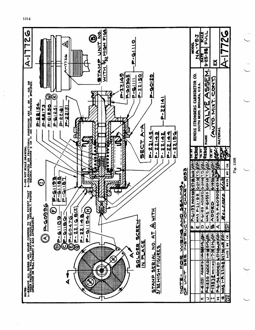
1314
@o
b b \._A .vnn
0
d- l
ol
fl
EI7l
j-cctzJ4eluoozIl-o
I|5tuflol
4
g$I
0.
0IL
0t
It
iffii
ffil
olol:lold.l
e-o. f
@
t9rolsloldl@
fl6rielqE
T1 o
5B*fi
HE?$aa2 P
;saliFtEee3sE!13iiH
stl*l1-0{tu
obtca9lL
TgTGIo\r|
trl.o l
E?|ll
|iil
\9NIl'-F-z
ot ?s$
io
dg,
49 <EgE a1 -
I ' E
2 eH 9E sF Evr i .
= gozEIE
zlHIqtdl
)lslrd-z
F-UUi*
tP?sFls
IrdF
E' bi Br E
$N, U, r8- e
$$\rt
sI\\
d1tr
cij-
oj-
ot '
ta
nFcc!
7'o.Uiq
a
IPo
@tJl5s d
ut{!
Eooc|'|e3d.
@
9n,n,do
a?
odoo{oI0d_
ooU|oI&a
0Itlo0(
0 loooodog
ctgqqi
{R
L w 0 t, a t irHt t
$i $$$I
v()
T5t9
frD
taI r
Emtr!I@oClr{tLo{
o
FC
I
fFrl-
c|'l
FrO
nF
A
altloo(vrq,o
I
a
q
daIJ
orOoad-
o||,Et
$l(flLfto-t
oulooctead
Y f H T rtPFr:
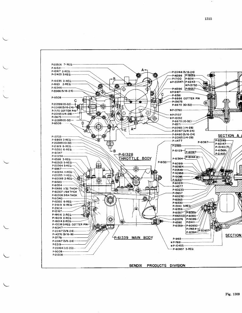
1315
P-20506 7-REQ.
P-6r331-P.|?t67 z-REa.Ft2403 2-REQ:
P-6t235 2-REQ;P-6il2t 2-REO.P-6t346P-20r65 F/t6-2
P-8508
P-20399(P-2Or66 (5/r6-24)P-717O COTTER PIF20r65 fl/4-P-r3675P-20399flo-32)-P-8508-
P-t3733P-6869 z-REQ.P-20399 (lO-3e)P-2r8r9 6-REO.P-t5350 6-REQ.--P-6r347P-60234P-6588 3-REQ;P-60303 5-REQ:P-20364 5-REQ:P-6867P-60244 |P-20355 i l-REQ:P-60089 2-REQ:P-6r320P-6r354P-ro666 t/32P-60307 t/64THrCKP-60308 3/64THlCKP-6t340P-r5350 6-REQ.P-2 r8 r9 6 -REQ;P-2924P-r? r67P-tg6t6 z-REO.P-r60r9 z-REQ.P-r60r4 2-REQ;P-ro238 aREa. COTTERP-6t34P-20167 F/A-241P-t4376 (9/16-r8)P-3779P-20r67 $/e-Z4lP-531P-20t64 U/2-P-9008
0166 (5/16-24)-P-r659s
lp--T-pagose-FrTroo lF929r-xP-2O347-l P-6243]
l*P-|373-Fr6ss6 tElros?,(P-918
6581
Ft3675P-6670 00-3
icP-r3760
*P-r7r37
66 OOTTER PII{
!-'19?1-lp+ogs
P-6r328
P-6I339 MAIN BODY
?-t?252P-6670 (rO-32)P-6571P-zOr65 (t/4-28't
20t67 (3/8-24'P-8460 (5/t6-24'P-2Of65 (t/4-?81P-l1477
P-r9086
P-6023P44577P-60233P-r3657P_6O252-
P-r3r40 3-REP-6135F6r35P-r66tO(2P-20376P-6592 lF2l4l
SEGTION A /
P-60r4P-13r40 (P-
SECTION
*P-7881xP-ro455
P-60857 3-REO.
P-zt208
rvtstoN
Fig. 1309
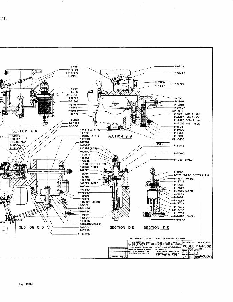
1 3 1 5
P-9745P-t3726P-6r3r6P-t7r48
P-8880P-60ilOP-9201A-t7726P-6r341
P-6668P-r3898Fr37
P-60224P-60228
P-2924P-4627
SECTION B B
SECTION D D SECTION E E
IO IE .COIPLCIE SE t OF gASI t lS FOF C lReuR€rOn P -6 t J6g
l /32 THrCKt/64 THrCK3/64 THrCKr/ t6 THtcK
)
SECTION A AP-601P-60t47.Pr3r40(P-61
SECTION C C
P-r4376F37Fr3897 z-REQ.P-r7099P-16597
P-ro252F155P-70277
P-6P-7I7O COTTERP-6r336
P-6r349
P-2r805P-6r3t9P-2Of64 {n'�t-zo'�)P-53r9
*P-2r454Ft6790P€5O8P-6564P-r4825P-ro248 F/e-241
P-r3531P-[640P-19285P-60627
*P-r7r7r3r9
P-t4425?-t4426P- t4427P€5O8P-20ro9P-6558P-r3680
xP-1o455
t342
P-6r343
P-7037r z-REQ.
P-6r333P.7I7O 3-REQ. COTTERP-13877P-r3775P-ro9t8P-r3876
3-REO.
r3875 3-REO.P-t3873
r9283749
Fr7329*P-r3737
r3735165 (r/4-28)
P-60973
PIN
\ - P - 6 t 3 t 5P-t7423
*P.|7425
P-20351P-61P-6r3
rOR SPECIAL PATY3 ANO9EE3 0F VAnrltLE PAntSitf ln to crnoue:ron3PgCr f r cA t ro t t h [EYs .
00 xot StEcrfY l t tgoaaf, i la iuaagR ot oRo€t3
c l vE rA I t A ro € io t i ftooEl For fhrcH caPouP€roFrs oR0 f ,RE0 .
G IY I SENIAL TU IOCN OFcaReucEron r ; Po99 to tE|HE I OROfF I I€ 'AR?O.
STROT'8ERG CAREURETOR
Fie. 1309
1401
Scintilla SB9R magnetos employ the principleof rotating magnet and stationary coil. Rotationof the four pole magnet produces reversals of themagnetic flux through the core of the coil. Thisproduces a high tension current in the secondaryivinding. Ttrls high tension current is conductei
CIIAPTER XIV
MAGNETOS
GENERAL CONSTRUCTION(Type SB9R)
DISASSEMBLY
by the distributor to the spark plugs.The condenser, connected across the breaker
cont4cts, is located on top of the coil. Thehreaker is held in position by two hold-downsprings which makes it quickly removable forinspection without the use of tools.
The following procedure of disassembly isrecommended to avoid any possibility of break-age. As the parts are removed, place them inorder on the bench to facilitate reassembly.
Dlstrlbutor Blocks-Remove the distributorblocks after having released their spring clamps.
Magneto Coll Cover-Take out the two fasten-ing screws and lift offcover.
Breaker Cover-Remove safety pin and breakercover fastening screw, after which the cover canbe removed.
Magneto Coll-Remove the two coil fasteningscrews and clamps after which the coil can beremoved. Care must be taken so as not to breakor damage the high tension carbon brush whenremoving the coil. The felt pad under the coilcan be taken out by hand.
Contaot Breaker Assernbly-Remove thebreaker assembly after having taken out the twobreaker hold-down springs. On fixed sparkmagnetos, also remove the clamp assembly whichsecures the breaker cup to the housing.
Remove the contact point assembly after tak-ing out its two securing screws. Inspect thecontact point assembly as outlined under "In-
spection of Contact Point Assembly".
Front End Plate, Rotatlng Magnet, andMagneto Ilouslng-Remove the front end plateafter having taken out its two securing screwsand the four lock nuts. Use Socket WrenchNo. 4-1337 for the lock nuts. Tap each sideof the front end plate lightly with a rawhidemallet to remove it from the housing.
Remove the distributor cylinder after pryingout the lock ring with a small screw driver.
Remove the cup from the end of the largedistributor gear hub. Unscrew the lock nutson the end of the distributor gear axle and lift offthe distributor gear. Do not loosen the two
screws which sec'rre the distributor gear axleto the front end qlate-unlgss the axle is-damagedand must be replaced. This will maintain lheoriginal adjustment fo1 t_he gears. The top balland cage assembly and the spacer with the shimwashers will come out as lobse parts when thedistributor gear is lifted from tlie axle. Makesure that the same spacer and shlrn washersare used when reassembling as this will give,in the majority of cases, the correct adiustmenfbetween the axle and gear. It is goodpracticeto wire.the spacer and shim to one ball and cageassembly to prevent from being misplaced.
If the bearings of the distributor gear axle needreplacement, the outside race foi the bearingwhich came out as a loose part and, also, th6complete bearing and retainer at the othef endof the gear hub, must be pressed out. To facili-tate this, it is suggested that a small pressing discof the size and shape shown in Fig. 1401 be used.This disc can be placed inside oT the sear hubwith its flat face in contact with each outer raceas indicated.
Remove the rotating magnet from the housingand place it on a clean part of the bench to mak6sure that small chips oi particles do not come incontact wlth rt.
Remove the insulating plate from the housingafter having taken out its two securing screwswhich also hold the safety gap bridge.
Replacernent of Drlve Shaft and BreakerEnd Ball Bearlngs-If any one part of a ballbearing is defective and needs replacement, thecornplete bearlng rnust be replaced.
The outer ball races are insulated from themagneto by insulating strips and are also backedby washers of the same material as used in theinsulating strips.
Remove the outside race from the front endplate with Puller No. 4-222 and remove the in-side race from the magnet with Puller No. 4-243.
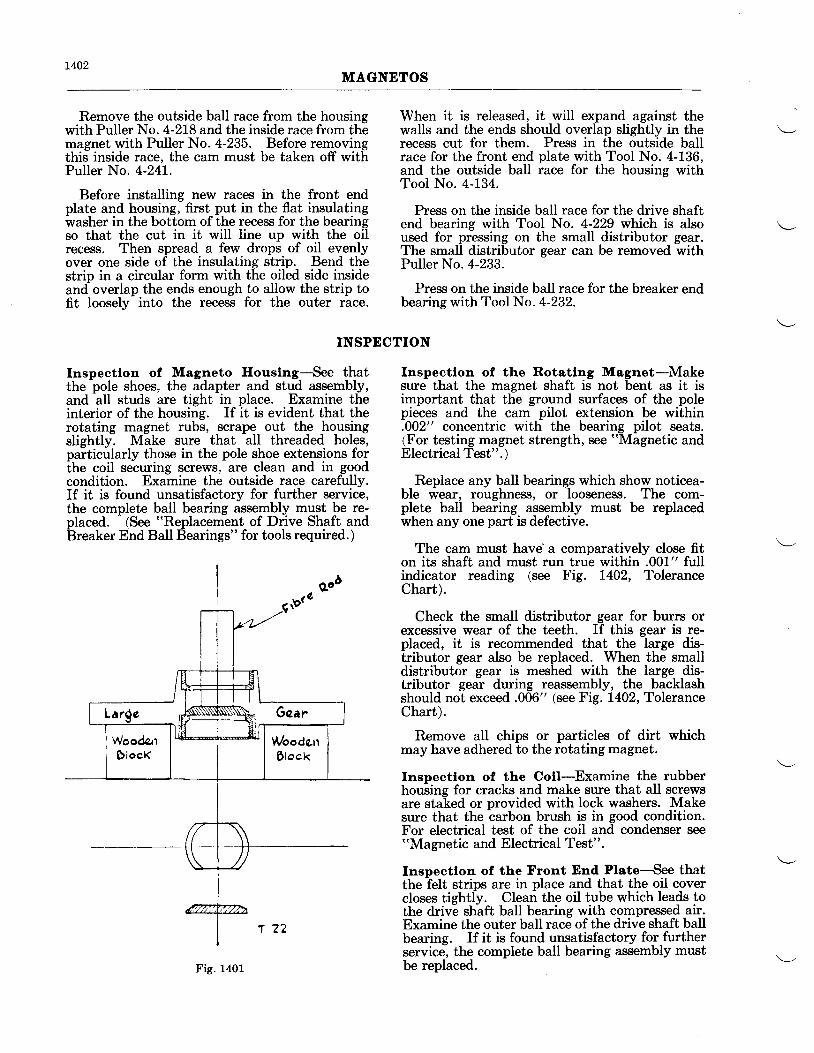
t402MAGNETOS
Remove the outside baII race from the housingwith Puller No. 4-218 and the inside race from themagnet with Puller No. 4-235. Before removingthis inside race, the cam must be taken off withPuller No. 4-241.
Before installing new races in the front endplate and housing, first put in the flat insulatingwasher in the bottom of the recess for the bearingso that the cut in it will line up with the oilrecess. Then spread a few drops of oil evenlyover one side of the insulating strip. Bend thestrip in a circular form with the oiled side insideand overlap the ends enough to allow the strip tofit Ioosely into the recess for the outer race.
When it is released, it will expand against thewalls and the ends should overlap slightly in therecess cut for them. Press in the outside ballrace for the front end plate with Tool No. 4-136,and the outside ball race for the housing withTooI No. 4-134.
Press on the inside ball race for the drive shaftend bearing with Tool No. 4-229 which is alsoused for pressing on the small distributor gear.The small distributor gear can be removed withPuller No. 4-233.
Press on the inside ball race for the breaker endbearing with Tool No. 4-232.
INSPECTION
Inspectlon of Magneto lfouslng-See thatthe pole shoes, the adapter and stud assembly,and all studs are tight in place. Examine theinterior of the housing. If it is evident that therotating magnet rubs, scrape out the housingslishtlv. Make sure that all threaded holes,paiticularly those in the pole shoe extensions forthe coil securing screws, are clean and in goodcondition. Examine the outside race carefully.If it is found unsatisfactory for further service,the complete ball bearing assembly must be re-placed. (See "Replacement of Drive Shaft andiJreaker End Ball Bearings" for tools required.)
Inspectlon of the Rotatlng Magnet-Makesure that the magnet shaft is not bent as it isimportant that the ground surfaces of the polepieces and the cam pilot extension be within.002" concentric with the bearing pilot seats.(For testing magnet strength, see "Magnetic andElectrical Test".)
Replace any ball bearings which show noticea-ble wear, roughness, or looseness. The com-plete ball bearing assembly must be replacedwhen any one part is defective.
The cam must have'a comparatively close fiton its shaft and must run true within .001" fullindicator reading (see Fig. L402, ToleranceChart).
Check the small distributor gear for burrs orexcessive wear of the teeth. If this gear is re-placed, it is recommended that the large dis-tributor gear also be replaced. When the smalldistributor gear is meshed with the large dis-tributor gear during reassembly, the backlashshould not exceed .006" (see Fig.1402, ToleranceChart).
Remove all chips or particles of dirt whichmay have adhered to the rotating magnet.
Inspectlon of the Coll-Examine the rubberhousing for cracks and make sure that all screwsare staled or provided with lock washers. Makesure that the carbon brush is in good condition.For electrical test of the coil and condenser see"Magnetic and Electrical Test".
Inspectlon of the Front End Plate-See thatthe
-felt strips are in place and that the oil cover
closes tightly. Cleari the oil tube which Ieads tothe drive shaft ball bearing with compressed air.Examine the outer ball race of the drive shaft ballbearing. Ifit is found unsatisfactory fol furtherservice, the complete ball bearing assembly mustbe replaced.Fig. 1401
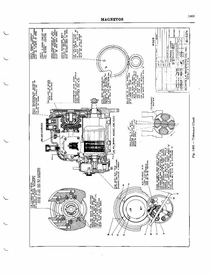
1403MAGNETOS
rrr6{,
l
I
l uzI 'U .ar {
7 ;LXI> rl < ;-20(t)
F= e J
- o o
u Pz :# PL l tI t J
; 6 0t- T r
' t
:l
I
l
oNro
H ,
::; grP i - r d3fr'.' l=iH;c;F != l i
;r l l , 3E" t : 5 ! , i x6 " r o ' L a -
;E:!E;EEE:iJ 6::$gfii: :l;l
E ; ii d dl 6 0
P U; ! e= t f0 < c2
5 j j
a l
a
Ia9
:6I li
:i i[(: i ! i ;lirsieE- l r sn
ii!;:ri r z c < < >5 t [H " i2 : 6 0 j z
i 3 iU;J
o . - -
i i iZ"o
^ 4
3 i zlE ri : l@ u c
f;F: gfil:'.a9",Itr" 3} < E F
^Hpt ig ;
33 ds
E g ; ;z o 9 . , , ,H 3 H E Q
o o
lEli it! ' J t i . lt x , o . ,
i ; ! ! 3;u ! ; o o! 3 i s
I
O0)
I0)
ti
I6l
d
bi
2
c
E -..1 'u
iiriii;i;i. e l E * . S I : d
fiE,riii;;:i;qiits*:!r:tgi:q: i;:::;H;i;E
ooF
o!
z9
2
F
=t
!
ot
0
2
i!:r--:] ;= 3 IE r Iaz i l Ie Rt li hPlF i= lr 2 0 lu uo l
zo
o d9 z2 wi FC Nt o
: ,r R
i :2 t
tI
?a4.Je L
hE, =: i
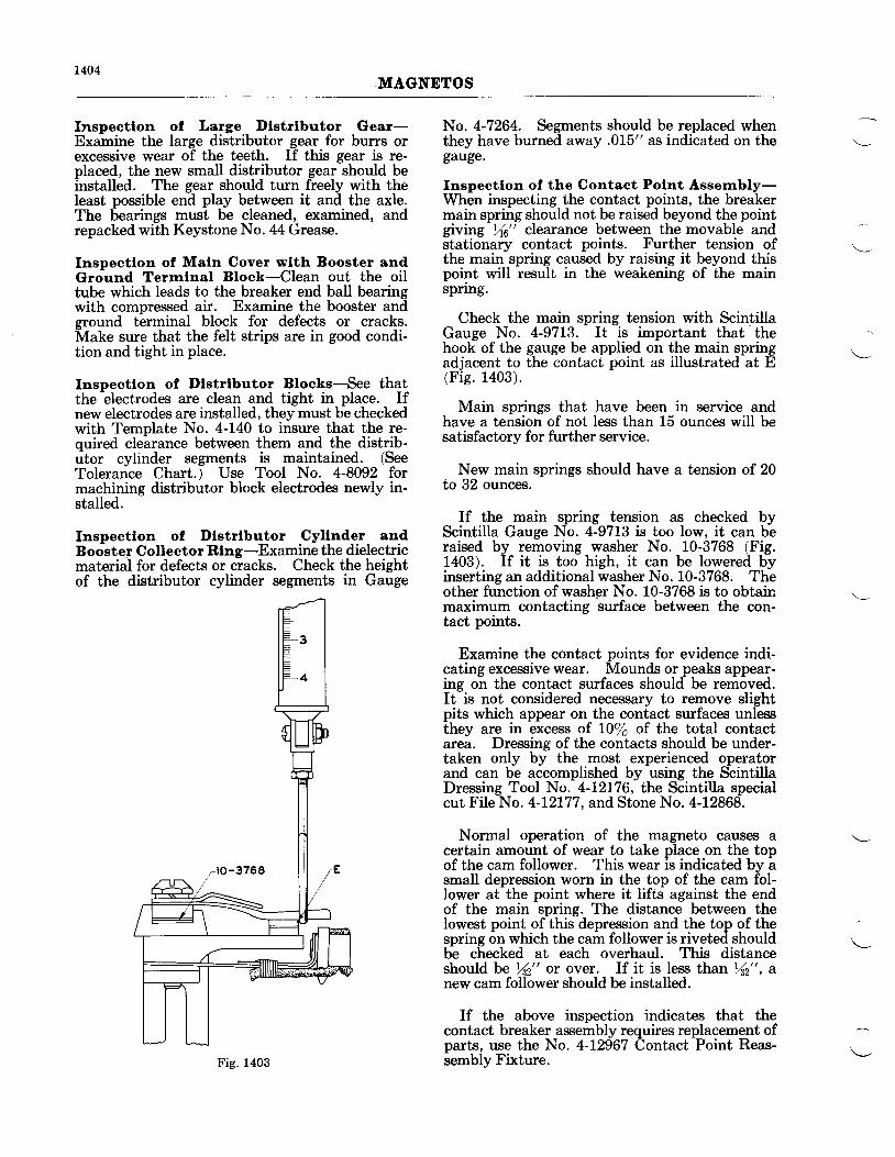
1404MAGNETOS
fnspectlon of Large Dlstrlbutor Gear-Examine the large distributor gear for burrs orexcessive wear of the teeth. If this gear is re-placed, the new small distributor gear should beinstalled. The gear should turn freely with theleast possible end play between it and the axle.The bearings must be cleaned, examined, andrepacked with Keystone No. 44 Grease.
Inspectlon of Maln Cover wlth Booster andGround Terrnlnal Block-Clean out the oiltube which leads to the breaker end ball bearingwith compressed air. Examine the booster andground terminal block for defects or cracks.Make sure that the felt strips are in good condi-tion and tight in place.
Inspectlon of Dlstrlbutor Bloaks-See thatthe electrodes are clean and tight in place. Ifnew electrodes are installed, they must be checkedwith Template No. 4-L40 to insure that the re-quired clearance between them and the distrib-utor cylinder segments is maintained. (SeeTolerance Chart.) Use Tool No. 4-8092 formachining distributor block electrodes newly in-stalled.
fnspectlon of Dlstrlbutor Cyllnder andB oolt er C ollector Rlng -Examine the dielectricmaterial for defects or cracks. Check the heightof the distributor cylinder segments in Gauge
No. 4-7264. Segments should be replaced whenthey have burned away .015" as indicated on thegauge.
Inspectlon of the Contaot Polnt Assernbly-When inspecting the contact points, the breakermain spring should not be raised beyond the pointgiving Yrc" clearance between the movable andstationary contact points. Further tension ofthe main spring caused by raising it beyond thispoint will result in the weakening of the mainsprrng.
Check the main spring tension with ScintillaGauge No. 4-9713. It is important that
.the
hook of the gauge be applied on the main springadjacent to the contact point as illustrated at E(Fig. 1403).
Main springs that have been in service andhave a tension of not less than 15 ounces will besatisfactory for further service.
New main springs should have a tension of 20to 32 ounces.
If the main spring tension as checked byScintilla Gauge No. 4-9713 is too low, it can beraised by removing washer No. 10-3768 (Fig.1403). If it is too high, it can be lowered byinserting an additional washer No. 10-3768. Theother function of washgr No. 10-3768 is to obtainmaximum contacting surface between the con-tact points.
Examine the contact points for evidence indi-cating excessive wear. Mounds or peaks appear-ing on the contact surfaces should be removed.It is not considered necessary to remove slightpits which appear on the contact surfaces unlessthey are in excess of I0/o of the total contactarea. Dressing of the contacts should be under-taken only by the most experienced operatorand can be accomplished by using the ScintillaDressing Tool No. 4-12L76, the Scintiila specialcut File No. 4-12177, and Stone No. 4-12868.
Normal operation of the magneto causes acertain amount of wear to take place on the topof the cam follower. This wear is indicated by asmall depression worn in the top of the cam fol-lower at the point where it lifts against the endof the main spring. The distance between theIowest point of this depression and the top of thespring on which the cam follower is riveted shouldbe checked at each overhaul. This distanceshould be /n" or over. If it is less than Yn", dnew cam follower should be installed.
If the above inspection indicates that thecontact breaker assembly requires
Fig. 1403
parts, use the No. 4-12967 Csembly Fixture.
rires replacement ofontact Point Reas-
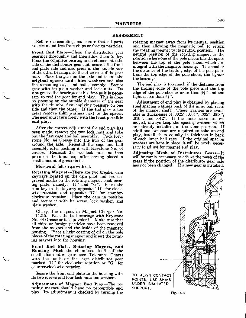
r405MAGNETOS
REASSEMBLYBefore reassembling, make sure that all parts
are clean and free from chips or foreign particles.
Front End Plate-Clean the distributor gearbearings thoroughly and then allow them to dry.Press the complete bearing and retainer into theside of the distributor gear hub nearest the frontend plate side and also press in the outside raceof the other bearing into the other side of the gearhub. Place the gear on the axle and install theorlglnal spacer and shlm washers and alsothe remaining cage and ball assembly. Securegear with its plain washer and lock nuts. Donot grease the bearings at this time as it is neces-sary to test the gear fbr end play. This is doneby pressing on the outside diameter of the gearwith the thumbs, first applying pressure on oneside and then the other. If the end play is toogreat remove shim washers next to the spacer.The gear must turn freely with the least posslbleend play.
After the correct adjustment for end play hasbeen made, remove the two lock nuts and takeout the first cage and ball assembly. Pack Key-stone No. 44 Grease into the hub of the geararound the axle. Reinstall the cage and ballassembly after packing it with Keystone No. 44Grease. Reinstall the two lock nuts and thenpress on the brass cup after having placed asmall amount of grease in it.
Moisten all felt strips with oil.Rotatlng Magnet-There are two breaker camkeyways located on the cam pilot and two en-graved marks on the rotatihg magnet back bear-ing plate, namely, "D" and "G". Place thecam key in the keyway opposite "D" for clock-wise rotation and opposite "G" for counter-clockwise rotation. Place the cam in positionand secure it with its screw, lock washer, andplain washer.
Charge the magnet in Magnet Charger No.4-14215. Pack the ball bearings with KeystoneNo. 44 Grease or its equivalent. Make sure thatall chips or foreign particles have been removedfrom the magnet and the inside of the magnetohousing. Place a light coating of oil on the polepieces of the rotating magnet and insert the rotat-ing magnet into the housing.
Front End Plate, Rotatlng Magnet, andIlouslng-Mesh the chamfered tooth of thesmall distributor gear (see Tolerance Chart)with the tooth on the large distributor gearmarked "D" for clockwise rotation or "G" forcounter-clockwise rotation.
Secure the front end plate to the housing withits two screws and four lock nuts and washers.
Adjustrnent of Magnet End Play-The ro-tating magnet should have no perceptible endplay. Its adjustment is checked by turning the
rotating magnet away from its neutral positionand then allowing the magnetic pull to returnthe rotating magnet to its neutral position. Theneutral position of the rotating magnet is theposition where one of the pole pieces fills the spacebetween the top of the pole shoes which areintegral with the magneto housing. The smallerthe distance of the trailing edge of the pole piecefrom the top edge of the pole shoes, the tighterthe bearings.
The end play is too much if the distance fromthe trailing edge of the pole piece and the topedge of the pole shoe is more than fu" and tootight if less than /s".
Adjustment of end play is obtained by placingsteel spacing washers back of the inner ball racesof the magnet shaft. These washers are avail-able in thicknesses of .0025", .004",.005", .008",.0L0", and .012". If the inner races are re-moved, always keep the spacing washers whichare already installed, in the same position. Ifadditional washers are required to take up endplay, install them equally in thickness in backof each inner ball race. If the original spacingwashers are kept in place, it will be rarely neces-sary to adjust for magnet end play.
Adjustlng Mesh of Dlstrlbutor Gears-Itwill be rarely necessary to adjust the mesh of thegears if the position of the distributor gear axlehas not been chahged. If a new gear is installed,
TO ALIGN CONTACTPOINTS, USE SHIMSUNDER INSULATEDSUPPORT.
Fig. 1404
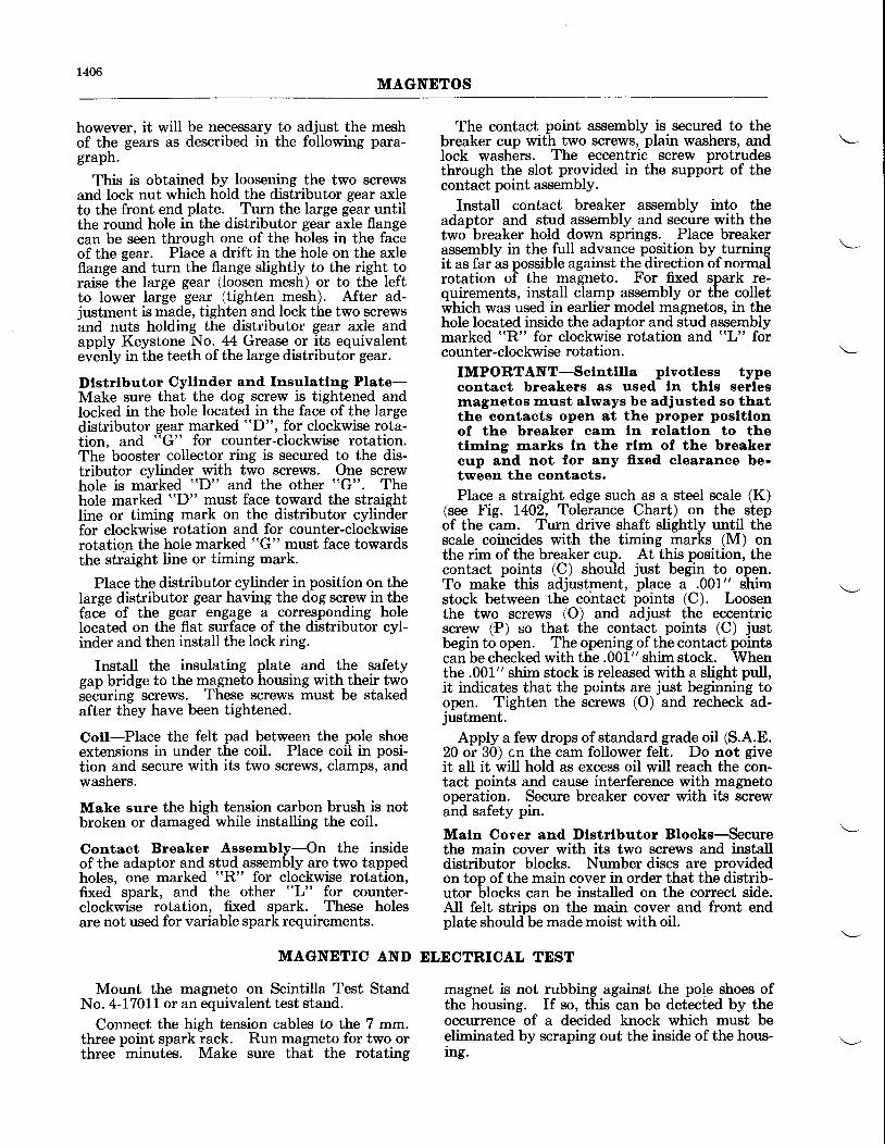
1406MAGNETOS
however, it will be necessary to adjust the meshof the gears as described in the following para-graph.
This is obtained by loosening the two screwsand lock nut which hold the distributor gear axleto the front end plate. Turn the large gear untilthe round hole in the distributor gear axle flangecan be seen through one of the holes in the faceof the gear. Place a drift in the hole on the axleflange ind turn the flange slightly to the right toraise the large gear (loosen mesh) or to the leftto lower large gear (tighten mesh). After ad-iustment is made, tighten and lock the two screwsand nuts holding the distributor gear axle andapply Keystone No. 44 Grease or its equivalentei""iy in ihe teeth of the large distributo-r gear.
Dlstrlbutor Cyllnder and fnsulatlng Plate-Make sure that the dog screw is tightened andlocked in the hole located in the face of the largedistributor gear marked "D", for clockwise rota-tion. and "G" for counter-clockwise rotation.The booster collector ring is secured to the dis-tributor cylinder with two screws. One screwhole is marked "D" and the other "G". Thehole marked "D" must face toward the straightline or timing mark on the distributor cylinderfor clockwise rotation and for counter-clockwiserotation the hole marked "G" must face towardsthe str'aight line or timing mark.
Place the distributor cylinder in position on thelarge distributor gear having the dog screw in theface of the gear engage a coruesponding holelocated on the flat surface of the distributor cyl-inder and then install the lock ring.
Install the insulating plate and the safetygap bridge to the magneto housing with their twoseCuring screws. These screws must be stakedafter they have been tightened.
Cotl-Place the felt pad between the pole shoeextensions in under the coil. Place coil in posi-tion and secure with its two screws, clamps, andwashers.
Make sure the high tension carbon brush is notbroken or damaged while installing the coil.
Contact Breaker Assernbly-On the insideof the adaptor and stud assembly are two tappedholes, one marked "R" for clockwise rotation,fixed spark, and the other "L" for counter-clockwise rotation, fixed spark. These holesare not used for variable spark requirements.
The contact point assembly is secured to thebreaker cup with two screws, plain washers, andlock washers. The eccentric screw protrudesthrough the slot provided in the support of thecontact point assembly.
Install contact breaker assembly into theadaptor and stud assembly and secure with thetwo breaker hold down springs. Place breakerassembly in the full advance position by turningit as far as possible against the direction of normalrotation of the magneto. For fixed spark re-quirements, install clamp assembly or the colletwhich was used in earlier model magnetos, in thehole located inside the adaptor and stud assemblymarked "R" for clockwise rotation and "L" forcounter-clockwise rotation.
IMPORTANT-Sclnttlla plvotless typecontaet breakers as used ln thls serlesmagnetos must always be adjusted so thatthe contacts open at the proper posltlonof the breaker carn ln relatlon to thetlrnlng marks ln the rlrn of the breakercup and not for any ffxed clearanoe be-tween the contacts.Place a straight edge such as a steel scale (K)
(see Fig. 1402, Tolerance Chart) on the stepof the cam. Turn drive shaft slightly until thescale coincides with the timing marks (M) onthe rim of the breaker cup. At this position, thecontact points (C) should just begin to open.To make this adjustment, place a .001" shimstock between the cohtact points (C). Loosenthe two screws (O) and adjust the eccentricscrew (?) so that the contact points (C) justbegin to open. The opening of the contact pointscan be checked with the .001" shim stock. Whenthe .001" shim stock is released with a slight pull,it indicates that the points are just beginning toopen. Tighten the screws (O) and recheck ad-justment.
Apply a few drops of standard grade oil (S.A.E.20 or 30) cn the cam follower felt. Do not giveit all it will hold as excess oil will reach the con-tact points and cause interference with magnetooperation. Secure breaker cover with its screwand safety pin.
Maln Cover and Dlstrlbutor Blooks-'Securethe main cover with its two screws and installdistributor blocks. Number discs are providedon top of the main cover in order that the distrib-utor blocks can be installed on the correct side.AII felt strips on the main cover and front endplate should be made moist with oil.
MAGNETIC AND DLECTRICAL TEST
Mount the magneto on Scintilla Test StandNo. 4-17011 or an equivalent test stand.
Connect the high tension cables to the 7 mm.three point spark rack. Run magneto for two orthree minutes. Make sure that the rotating
magnet is not rubbing against the pole shoes ofthe housing. If so, this can be detected by theoccurrence of a decided knock which must beeliminated by scraping out the inside of the hous-rng.
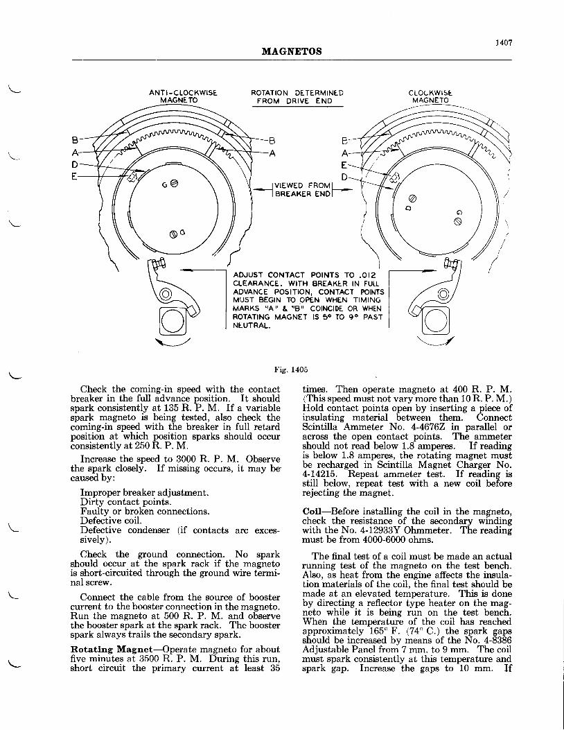
1407MAGNETOS
ANTI -CLOCKWISEMAGNETO
ROTATION DETERMINE DFROM DRIVE END
IVIEWED FROMII BREAKER ENDI
ADJUST CONTACT POINTS TO .OI2CLEARANCE. WITH BREAKER IN FUILADVANCE POSITION, CONTACT POINTSMUST BEGIN TO OPEN WHEN TIMINGMARKS IAII & qBX COINCIDE OR WHENROTATING MAGNET IS 50 TO 90 PASTNEUTRAL,
Fig. 1405
cLoCKwrstMAGNETO
Check the coming-in speed with the contactbreaker in the full advance position. It shouldspark consistently at 1ii5 R. P. M. If a variablespark magneto is being tested, also check thecoming-in speed with the breaker in full retardposition at which position sparks should occurconsistently at250 R. P. M.
Increase the speed to 3000 R. P. M. Observethe spark closely. If missing occurs, it may becaused by:
Improper breaker adjustment.Dirty contact points.Faulty or broken connections.Defective coil.Defective condenser (if contacts arc exces-sively).
Check the ground connection. No sparkshould occur at the spark rack if the magnetois short-circuited through the ground wire termi-nal screw.
Connect the cable from the source of boostercurrent to the booster connection in the magneto.Run the magneto at 500 R. P. M. and observethe booster spark at the spark rack. The boosterspark always trails the secondary spark.
Rotatlng Magnet-Operate magneto for aboutfive minutes at 3500 R. P. M. During this run,short circuit the primary current at least 35
\=/
times. Then operate magneto at 400 R. P. M.(This speed must not vary more than 10 R. P. M.)Hold contact points open by inserting a piece ofinsulating material between them. ConnectScintilla Ammeter No. 4-46762 in parullel oracross the open contact points. The ammetershould not read below 1.8 amperes. If readingis below 1.8 amperes, the rotating magnet mustbe recharged in Scintilla Magnet Charger No.4-142L5. Repeat ammeter test. If reading isstill below, repeat test with a new coil beforerejecting the magnet.
Cotl-Before installing the coil in the magneto,check the resistance of the secondary windingwith the No. 4-12933Y Ohmmeter. The readingmust be from 4000-6000 ohms.
The final test of a coil must be made an actualrunning test of the magneto on the test bench.Also, as heat from the engine affects the insula-tion materials of the coil, the final test should bemade at an elevated temperature. This is doneby directing a reflector type heater on the mag-neto while it is being run on the test bench.When the temperature of the coil has reachedapproximately 165" F. (74'C.) the spark gapsshould be increased by means of the No. 4-8386Adjustable Panel from 7 mm. to 9 mm. The coilmust spark consistently at this temperature andspark gap. Increase the gaps to 10 mm. If
t , t
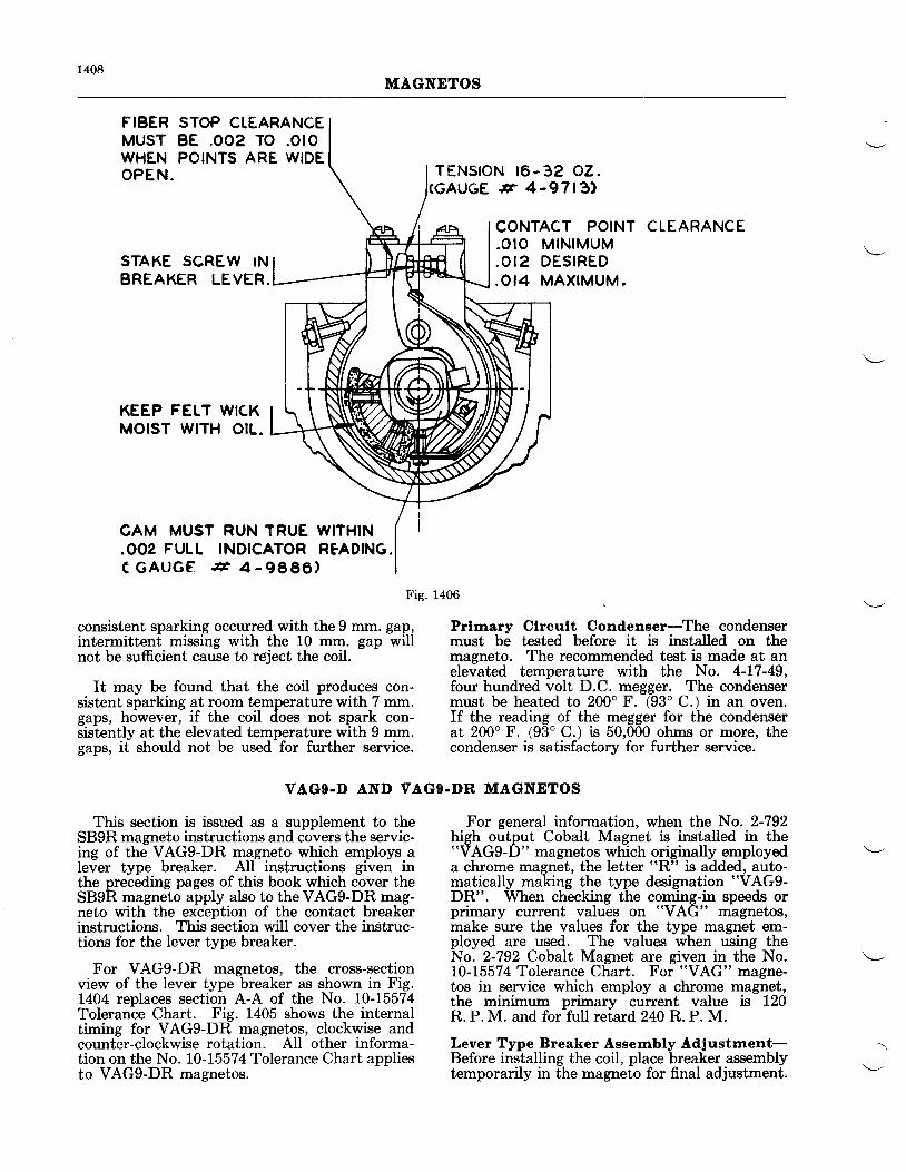
1408MAGNETOS
FIBER STOP CTEARANCEMUST BE .OO2 TO .OrOWHEN POINTS ARE WIDEO P E N .
STAKE SCREW INBREAKER LEVER.
KEEP FELT WICKMOIST W|TH OtL.
GAM MUST RUN TRUE WITHIN.OO2 FULL INDICATOR RFADING.C G A U G E 8 4 - 9 8 8 6 )
consistent sparking occurred with the 9 mm. gap,intermittent missing with the 10 mm. gap willnot be sufficient cause to reject the coil.
It may be found that the coil produces con-sistent sparking at room temperature with 7 mm.gaps, however, if the coil does not spark con-sistently at the elevated temperature with 9 mm.gaps, it should not be used for further service.
Fig. 1406
VAGg.D AND VAGO.DR MAGNETOS
Prhnary Clrcult Condenser-The condensermust be tested before it is installed on themagneto. The recommended test is made at anelevated temperature with the No. 4-L7-49,four hundred volt D.C. megger. The condensermust be heated to 200" F. (93" C.) in an oven.If the reading of the megger for the condenserat 200o F. (93" C.) is 50,000 ohms or more, thecondenser is satisfactorv for further service.
TENSfON t6-3�2 c�2.# 4-9713.)
CONTACT POINT.OIO MIN IMUM.OI2 DESIRED.OI4 MAXIMUM.
CLEARANCE
This section is issued as a supplement to theSB9R magneto instructions and covers the servic-ing of the VAG9-DR magneto which employs alever type breaker. AII instructions given inthe preceding pages of this book which cover theSB9R magneto apply also to the VAG9-DR mag-neto with the exception of the contact breakerinstructions. This section will cover the instruc-tions for the lever type breaker.
For VAG9-DR magnetos, the cross-sectionview of the lever type breaker as shown in Fig.1404 replaces section A-A of the No. L0-1.5574Tolerance Chart. Fig. 1405 shows the internaltiming for VAG9-DR magnetos, clockwise andcounter-clockwise rotation. AII other informa-tion on the No. L0-15574 Tolerance Chart appliesto VAG9-DR magnetos.
For general information, when the No. 2-792high output Cobalt Magnet is installed in the"VAG9-D" magnetos which originally employeda chrome magnet, the letter rrR" is added, auto-matically making the type designation "VAG9-
DR". When checking the coming-in speeds orprimary current values on "VAG" magnetos,make sure the values for the type magnet em-ployed are used. The values when using theNo. 2-792 Cobalt Magnet are given in the No.L0-15574 Tolerance Chart. For "VAG" magne-tos in service which employ a chrome magnet,the minimum primary current value is I20R. P. M. and for full retard 240F". P. M.
Lever Type Breaker Assernbly Adjustment-Before installing the coil, place breaker assemblytemporarily in the magneto for final adjustment.
1409MAGNETOS
Set the contact points with the Scintilla WrenchNo. 4-490 so that the clearance between them is.012" as measured with the feeler gase on theNo. 4-490 Wrench. With this adjuitLrent, theclearance between the back of the breaker armand the fibre stop should be from .002" to .010"when the contact points are wide open. Checkthis fibre stop clearance for each cam lobe.
Turn the magneto drive shaft until timingmarks "A" and "B" (Fig. 1405) are approxi-mately opposite each other. Place the breakerassembly in the full advance position. Turn the
drive shaft in the direction of rotation untilthe contact points begin to open. The pointsshould open when the timing marks "A" an4 "3"
are opposite each other or when the rotatingmagnet is 5" to 9o past its neutral position asmeasured with the Scintilla Timing Disc No.4-25L2.
After adjustment is made, remove breakerassembly and install the coil, main cover, distrib-utor blocks, etc. Reinstall breaker assembly.
Other information pertaining to lever typebreakers is given in Fig. 1406.
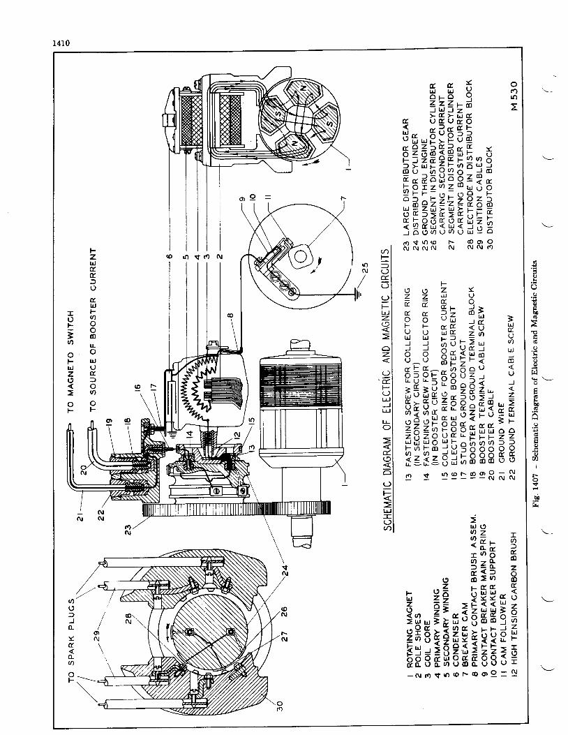
o€
lr
+to
bD
6
h€o
ku0
q)
aII
t.-
b0
1410
t & X orrJ lrJ Y (oO p O I ! o
1 7 4 r dj v l S "t U ( r U a O
u f f , P : P a apZgPEB r [, gP : ; E g H E : ; Ib P E l : 4 i 8 " Po B e r Z r Z & = " err=-*fi3fitg6h
l-
2 2 f r [u t ; J >
5 5 = " A i F =I [ $ q * - Hi : h d r E q n ' 'd d R s I * r " d 3o ^ u b H i F < m
8 5 5 c q S g 2 : 5:H : iXs 2A t - iH : H " a Z x A 9 ; d - =9 - G 9 : A X E o h <: 43 " ' " ; ; : z rog , - f iZAZE EP"ef E"vezt J t r u J O L l ! : n a O O > =t o i : o - 1 i ' l 5 o o o o 93 = 3 = s ; ; 9 8 8 5 s
u J ( ,u ) z r2x* -gr o 6 E 'o z t t of = q z
o 5 : A Bh 2 6 F g g n g
ftsiga#gllr- N r o s r o r o F o o o - $
o(,lJ(L
:(t
(LU)
oF
' f i s l n ( o F @ o oi r i c u c v r u N N N f ? )
(r) A
pl= l( ) lE l" l(J lF lLrJ Iz. l< l> l
Io lz l< l
Io l
F l(J ll4J IJ l- ltt- Io l
I> l< ld.l(91< l6l(Jl
EI> ltrl I- l
3l
|oN
FzlrJttrJutllJ
T Fo gF \.'= O5 d lq l L
o oF rrjlrJ Uz to f ,
O OF F
@ F -
' o ( o r " e e R * s
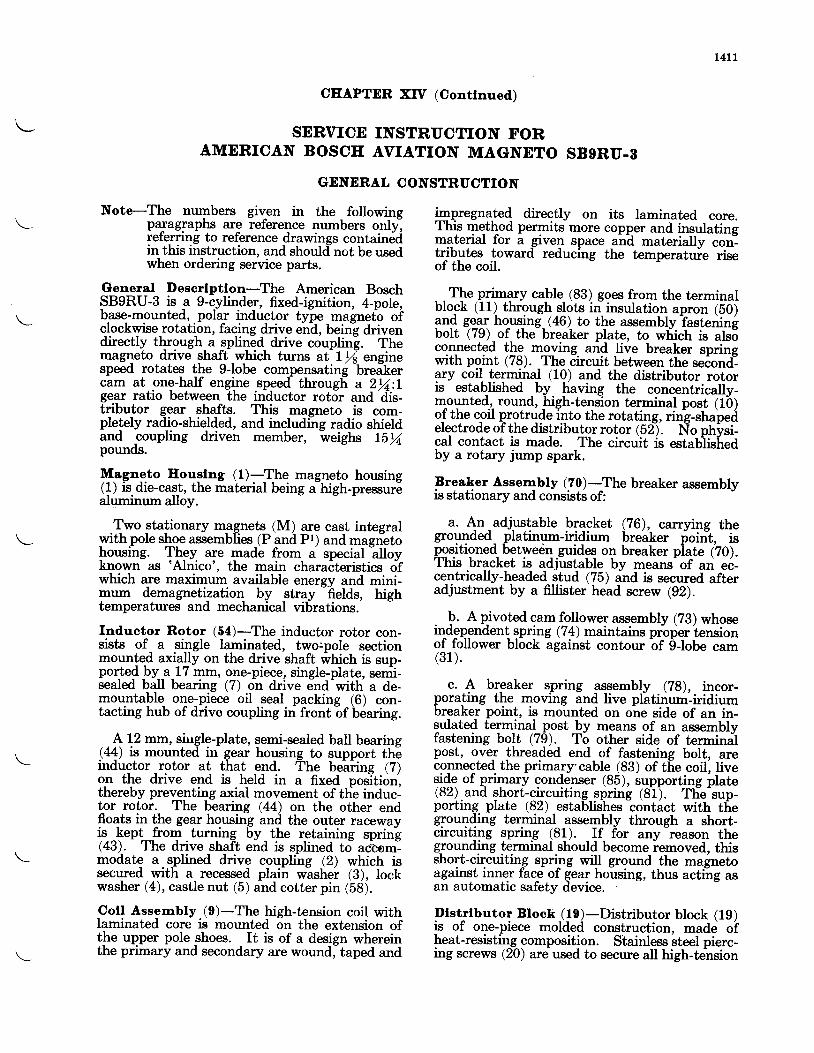
L4tt
CEAPTER XIV (Conflnued)
SERVICE INSTRUCTION FORAMERICAN BOSCE AVIATION MAGNETO SB9RU.S
GENERAL CONSTRUCTION
Note-The numbers given in the followingpalagraphs are reference numbers onlylreferring to reference drawings contain6din this instruction, and shouldnot be usedwhen ordering service parts.
General Desorlptlon-The American BoschSB9RU-3 is -a 9-c-ylinde_r, fixed-ignition, 4-pole,b-ase-mounted,.polar inductor type magnetb oi'clockwise-rotation, faqing drive eh-d, being drivendirectly through a qpli4ed drive coupling. Themagneto drive shaf,t -which turns at- Lrfi engsnespeed rotates the g-lobe compensatine breikercam at one-half engine speed througf, a 2fu:tgear ratio between the inductor rotor and'dis-tributor gear shafts. This magneto is com-pletely radio-shielded, and includine radio shieldand .coupling driven member, weighs LE%pounds.
$."gleg.to Houslng (l)-The magneto housing(!) is.die-cast, the material being fhigh-pressurealuminum alloy.
.Two stationary m_a_gnetq (M) are cast integralwithpole shoe assemblies (P and Pr) and magnetohousing. Tttpy ut" made from a special
-alloy
known as 'Alnico', the main charaiteristics ofwhich are maximum available enersy and mini-mum demagnetilation by stray
-helds, high
temperatures and mechanical vibrations.
Inductor Rotor (5a)-The inductor rotor con-sists of a single laminated, 1*s.pole sectionmounle-d axially on the drive shaft *trictr is sup-porJe{ !y a 17 mm, one-piece, single-plate, seni-sealed ball bearing (7) on drive end-with a de-mouatable- one-piece oil seal packing (6) con-tacting hub of drive coupling in front of briaring.
+\2 mm, siirgle-plate, semi-sealed ball bearing(11) is mounted in gear housing to support theinductor rotor at that end. The beaiing (Z)on the drive end is held in a fixed positiorythereby preventing axial movement of tlie induc-tor rotor. The bearinC eq on the other endfloats in the gear hgusing and the outer racewayis. ̂ lept_from . turning by _ the retaining spring(43). The drive shaft end is splined to ac'com-modate a splined drive couplins (2) which issecured with a recessed plain wishei 1B;, lockwasher (4), castle nut (5) and cotter pin (58).
Coll Assembly (O)-The high-tension coil withlaminated core is mounted on the extension ofthe upper pole shoes. It is of a design whereinthe primary and secondary are wound, taped and
impregnated directly on its laminated core.This method permits more copper and insulatingmaterial for a _givelr space ahd materially conltributes toward reducing the temperatuie riseof the coil.
_ - The primary cable (83) goes from the terminalblock (11) through slots in- insulation apron (b0)3ng CgqI ho^using. (46) to the assembly Tasteningbolt (79) of the breaker plate, to wliich is ab5connected the moving. and live breaker springwith point (78). The circuit between the secondary coil terminal (10) and the distributor rororis established -by. lraving the concentrically-mpgnted.,. round, high-tens-ion terminal post (1b)of the coil protrude into the rotating, ring-shapedelectrode of the distributg,r rotor (b2). No physi-cal contact is made. The circuit is estab'lisLedby a rotary jump spark.
Frea\er Assenlbly (?0)-!he breaker assemblyis stationary and consists of:
a. 4r.adjlstable bracket (76), carrying thegrouTded- -platinum-iridium breaker foini, ispositioned betwedn.guidgq on breaker piate (20).This bracket is adjustable by means of an e6-ce_ntrically-headed stud (75) and is secured afteradjustment by a fillister head screw (g2).
. b. A pjvoted cam follower a*sembly (?B) whoseindependent spring (74) maintains prbper iensionof follower block against contour bf globe cam(31) .
c. A br_eaker spring assembly (28), incor-porating the moving and live platinum-iridiumbreaker point, is mounted on one side of an in-sulated terminal post by means of an assemblyfastening bolt (79). To other side of terminalpost, ove-r threaded end of fastening bolt, areconnected. the prima,ry'cable (83) of tf,e coil, Iives.ide of prqnary condenser (85), supporting irlate(82).and short-circuiting spring (81). Tlie-sup-porting plate (82) establishes contact with thegrounding terminal assembly throueh a short-circuiting spring (81). If for anv-reason thegrounding terminal should become iemoved. this.564-cilcuitin^g spri-ng will ground the magnetoagainst inner fae.-e of gear housing, thus acting asan automatic safety device.
Dlstrlbutor Bloek ( l9)-Distributor block (19)is of one-piece molded construction, made oiheat-resistin_g- composition. Stainless bteel pierc-ing screws (20) are used to secure all high-tension
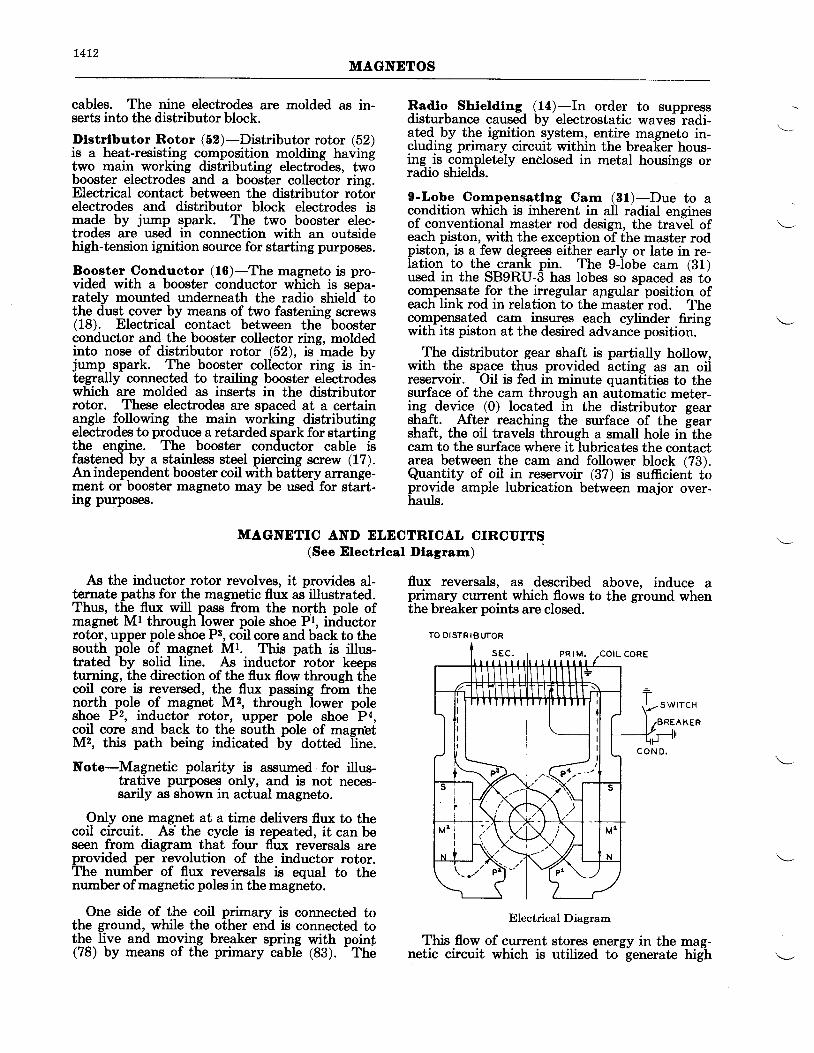
14L2MAGNDTOS
cables. The nine electrodes are molded as in-serts into the distributor block.
Dlstrlbutor Rotor (52)-Distributor rotor (52)is a heat-resisting composition molding havingtwo main working distributing electrodes, twobooster electrodes and a booster collector ring.Electrical contact between the distributor rotorelectrodes and distributor block electrodes ismade by jump spark. The two booster elec-trodes are used in connection with an outsidehigh-tension ignition source for starting purposes.
Booster Conductor (16)-The magneto is pro-vided with a booster conductor which is sepa-rately mounted underneath the radio shield tothe dustcover by means of two fastening screws(18). Electrical contact between the boosterconductor and the booster collector ring, moldedinto nose of distributor rotor (52). is made bvjump spark. The booster collector ring is in-tegrally connected to trailing booster electrodeswhich are molded as inserts in the distributorrotor. These electrodes are spaced at a certainangle f,ollowing ,the main working distributingelectrodes to produce a retarded spark for startingthe engine. The booster conductor cable isfastengd by a stainless steel piercing screw (17).An independent booster coil with battery arrange-ment or booster magneto may be used for start-rng purposes.
Radlo Shteldtng, (f4)-In order to suppressdisturbance caused by electrostatic waves radi-ated by the ignition system, entire magneto in-cluding primary circuit within the brealier hous-ing-is completely enclosed in metal housings orradio shields.
O-Lobe Corrrpensatlng Cam (31)-Due to acondition which is inherent in all radial enginesof conventional master rod design, the trav-el ofeach piston, with the exception of the master rodpiston, is a few degrees either early or late in re-Iation to the crank pin. The g-lobe cam (31)used in the SB9RU-3 has lobes so spaced as tocompensate for the irregular apgular position ofeach link rod in relation to the master rod. Thecornpensated cam_ insures each cylinder firingwith its piston at the desired advance position.
-
The distributor gear shaft is partially hollow,with the space thus provided icting is an oiireservoir. Oil is fed in minute quantities to thesurface of the cam through an automatic meter-ips _device (0) located in the distributor gearshaft. After reaching the surface of the gearshaft, the oil travels through a small hole in thecam to the surface where it lubricates the contactarea between the cam and follower block (73).Quantity of oil in reservoir (37) is sufficient ioprovide ample lubrication between major over-hauls.
MAGNDTIC AND ELECTRICAL CIRCUITS(See Electrleal Dlagram)
As the inductor rotor revolves, it provides al-ternate paths for the magnetic flux as illustrated.Thus, the flux will pass from the north pole ofmagnet Mt through lower pole shoe Pl, inductorrotor, upper pole shoe P3, coil core and back to thesouth pole of magnet Ml. This path is illus-trated by solid line. As inductor rotor keepsturning, the direction ofthe flux flow through thecoil core is reversed, the flux passing from thenorth pole of magnet M2, through lower poleshoe P2, inductor rotor, upper pole shoe Pa,coil core and back to the south pole of rnagn'etM2, this path being indicated bi.y dotted Iine.
Note-Magnetic polarity is assumed for illus-trative purposes only, and is not neces-sarily as shown in actual magneto.
OnIy one magnet at a time delivers flux to thecoil circuit. As'the cycle is repeated, it can beseen from diagram that four flux reversals areprovided per revolution of the inductor rotor.The number of flux reversals is equal to thenumber of magnetic poles in the magneto.
One side of the coil primary is connected tothe ground, wbile the other end is connected to15s llve and moving breaker spring with poinf(78) bV means of the primary cable (83).
- The
flux reversals, as described above, induce aprimary current which flows to the ground whenthe breaker points are closed.
TO DISTRIBUTOR
Electrical Diagram
This flow of current stores energy in the mag-netic circuit which is utilized to generate high
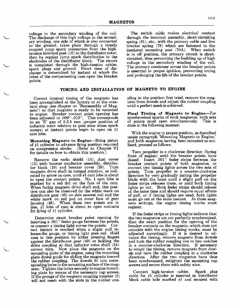
1413MAGNETOS
voltage in the secondary winding of the coil.The discharge of this high voltage in the second-arv winding, one side of which is also connectedto'the ground, takes place through a closelycoupled j*ttp spark connection from the high-tensfon terminal post (10) to the distributor rotor,then by regular l*"p spark distribution to theelectrodes of the distributor block. The circuitis completed through the high-tension cablss,snark plues and ground. Exact time of dis-charge
-is ?etermined by instant at which the
Iobes of the compensating cam open the breakerpoints.
Correct internal timing of the magneto hasbeen accomplished at the factory or at the over-haul shop (see chapter on 'Reassembly of Mag-neto') so that magneto is ready to be mountedto engine. Breaker contact point opening hasbeen adiusted to .009"-.010". This correspondsto an 'E' gap of 3-3.5 mm (proper position ofinductor rotor relative to pole shoe when sparkoccurs) at instant points begin to open on 11cam lobe.
Mountlng Magneto to Englne-Bring pistoqof #1 cylin-der to advance firing position requiredon compression stroke. (Refer to Chapter VIfor details on how to obtain this position.)
Remove the radio shield (14), dust cover(13) with booster conductor assembly, distribu-tor block (19) and breaker cover (39). Turnmagneto drive shaft in normal rotation, as indi-cated by arrow on cam, until 11 cam lobe is aboutto open the contact points. No. 1 cam lobe ismarked by a red dot on the face of the cam.When facing magneto drive shaft end, this posi-tion can also be observed by the white mark ondistributor gear (49) on side nearest coil and thewhite marli on red pad on inner face of gearhousine (46). When these two points are inline, #1 lobe of cam is about to open contactsfor fring of #1 cylinder.
Determine exact breaker point opening byinserting a .001" feeler gauge between the points,or connect a timing light across the points. Cor-rect instant is reached when a slight pull re-leases the gauge, or timing light goes out. Holdcam in this position by either pressing finge-rsasainst the dfutributor gear (49) or holding thediive coupling so that inductor rotor shaft (54)cannot turn.
- Now place the magneto on the
mounting plate of the engine, using the mountingplate dowel guide for sliding the magneto towardthe rubber coupling. The dowels fit into coffe-spondingholes in the mounting surface of the mag-neto. Tighten the latter securely to engine mount-ing plate by means of the necessary cap screws.If the pronis of the magneto coupling member (2)will not mesh with the slots in the rubber cou-
The switch cable makes electrical contactthrough the terminal assembly, short-circuitingspring (81), etc., with the primary cable and livebreaker spring (78) which are fastened to theinsulated mounting post (70A). When switchis in off position, the primary circuit is short-circuited, thus preventing the building up of highvoltage in the secondary winding of the coil.The primary condenser across the breaker pointsis essential to proper ignition, preventing arcingand prolonging the life of the breaker points.
TIMING AND INSTALLATION OF MAGNETO TO DNGINN
pling in the position first tried, remove the mag-neto from dowels and adjust the rubber couplinguntil a perfect mesh is achieved.
Ftnal Tfunlng of Magneto to Englne-Forsynchronized sparks of both magnetos, both setsof points must open simultaneously. This isdone in the following manner:
With the engine in proper position, as describedunder paragraph'Mounting Magneto to Engine,'and both magnetos having been mounted as out-lined, proceed as follows:
Turn propeller in a clockwise direction (facingfront of engine) until the breaker points haveclosed. Insert .001" feeler strips between thebreaker contact points of both magnetos, orconnect two timing lights across the two sets ofpoints. Turn propeller in a counter-clockwisedirection by very gradually jarring the propellerblade with the hand until a slight pull on thefeeler strips releases them, or until both timingIights go out. Both feeler strips should releaseat the same time and should require equal effortsof pull, or if timing lights are used, both lightsmust go out at the same instant. At these mag-neto. settings, the engine timing marks mustregrsrcr.
If the feeler strips or timing lights indicate thatthe two magnetos are not perfectly synchronized,then the exact position for the opening of thebreaker contacts on the magneto, which does notcoincide with the engine timing marks, must beadjusted accordingly. If it is desired to ad-vance the timing, remove magneto from dowelsand turn the rubber coupling one or two notchesin a counter-clockwise direction. If necessaryto retard the timing, remove magneto from dow-els and turn the rubber coupling in a clockwisedirection. After the two magnetos have thusbeen synchronized, retighten the mounting capscrews and secure them with safety wire.
Connect high-tension cables. Spark plugcable for 1L cylinder is inserted in distributorblock cable hole marked #1 and secured with
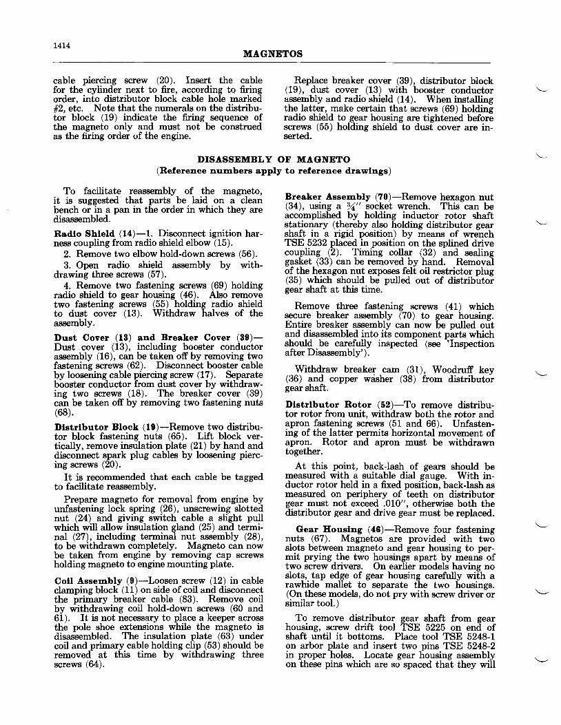
t4L4MAGNETOS
cable piercing screw (20). Insert the cablefor the cylinder next to fire, according to firingorder. into distributor block cable hole marked#2, etc. Note that the numerals on the distribu-tor block (19) indicate the firing sequence ofthe magneto only and must not be construedas the firing order of the engine.
To facilitate reassembly of the magneto,it is suggested that parts be laid on a cleanbench or in a pan in the order in which they aredisassembled.
Radto Shteld (14)-1. Disconnect ignition har-ness coupling from radio shield elbow (15).
2. Remove two elbow hold-down screws (56).3. Open radio shield assembly by with-
drawing three screws (57).4. Remove two fastening screws (69) holding
radio shield to gear housing (46). Also removetwo fastening screws (55) holding radio shieldto dust cover (13). Withdraw halves of theassembly.
Dust Cover (18) and Breaker Cover (80)-Dust cover (13), including booster conductorassembly (16), can be taken off by removing twofastening screws (62). Disconnect booster cableby Ioosening cable piercing screw (17). Separatebooster conductor from dust cover by withdraw-ing two screws (18). The breaker cover (39)can be taken off by removing two fastening nuts(68).
Dlstrlbutor Block (I0)-Remove two distribu-tor block fastening nuts (65). Lift block ver-tically, remove insulation plate (21) by hand anddisconnect spark plug cables by loosening pierc-ing screws (20).
It is recommended that each cable be taggedto facilitate reassembly.
Prepare magneto for removal from engine byunfastening lock spring (26), unscrewing slottednut (24) and giving switch cable a slight pullwhich will allow insulation gland (25) and termi-nal (27), including terminal nut assembly (28),to be withdrawn completely. Magneto can nowbe taken from engine by removing cap screwsholding magneto to engine mounting plate.
Coll Assembly (9)*Loosen screw (12) in cableclamping block (11) on side of coil and disconnectthe primary breaker cable (83). Remove coilby withdrawing coil hold-down screws (60 and61). It is not necessary to place a keeper acrosstthe pole shoe extensions while the magneto isdisassembled. The insulation plate (63) undercoil and primary cable holding clip (53) should beremoved at this time by withdrawing threescrews (64).
DISASSEMBLY OF MAGNDTO(Relerence numbers apply to relerence drawlngs)
Replace breaker cover (39), distributor block(19), dust cover (13) with booster conductorassembly and radio shield (14). When installingthe latter, make certain that screws (69) holdinEradio shield to gear housing are tight'en6d befor6screws (55) holding shield to dust cover are in-serted.
Breaker Assembly (70)-Remove hexagon nut(34), using a 32" socket wrench. This can beaccomplished by holding inductor rotor shaftstationary (thereby also holding distributor gearshaf! in a rigid position) by means of wrenchTSE 5232 placed in position on the splined drivecoupling (2). Timing collar (32) and sealinggasket (33) can be removed by hand. Removalof the hexagon nut exposes felt oil restrictor plug(35) which should be pulled out of distributoigear shaft at this time.
Remove three fastening screws (41) whichsecure breaker assembly 170) to gear housing.Entire breaker assembly can now be pulled outand disassembled into its component parts whichshould be carefully inspected (see 'Inspectionafter Disassembly').
Withdraw breaker cam (31), Woodruff key(36) and copper wdsher (3b)
'from distributoi.
gear shaft.
Dlstrlbutor Rotor (52)-To remove distribu-tor rotor from unit, withdraw both the rotor andapron fastening screws (51 and 66). Unfasten-ing of the latter permits horizontal movement ofapron. Rotor and apron must be withdrawntogether.
At this point, back-lash of gears should bemeasured with a suitable dial sauee. With in-ductor rotor held in a fixed posilion', back-lash asmeasured on periphery of teeth on distributorgear must not exceed .010", otherwise both thedistributor gear and drive gear must be replaced.
Gear Eoustng (46)-Remove four fasteningnuts (67). Magnetos are provided with twoslots between magneto and gear housing to per-mit prying the two housings apart by means oftwo screw drivers. On earlier models having noslots, tap edge of gear housing carefully with arawhide mallet to separate the two housings.(On these models, do not pry with screw driver orsimilar tool.)
To remove distributor gear shaft from gearhousing, screw drift tool TSE 5225 on end ofshaft until it bottoms. Place tool TSE 5248-1on arbor plate and insert two pins TSF, 5248-2in proper holes. Locatn gear housing assemblyon these pins which are so spaced that they will
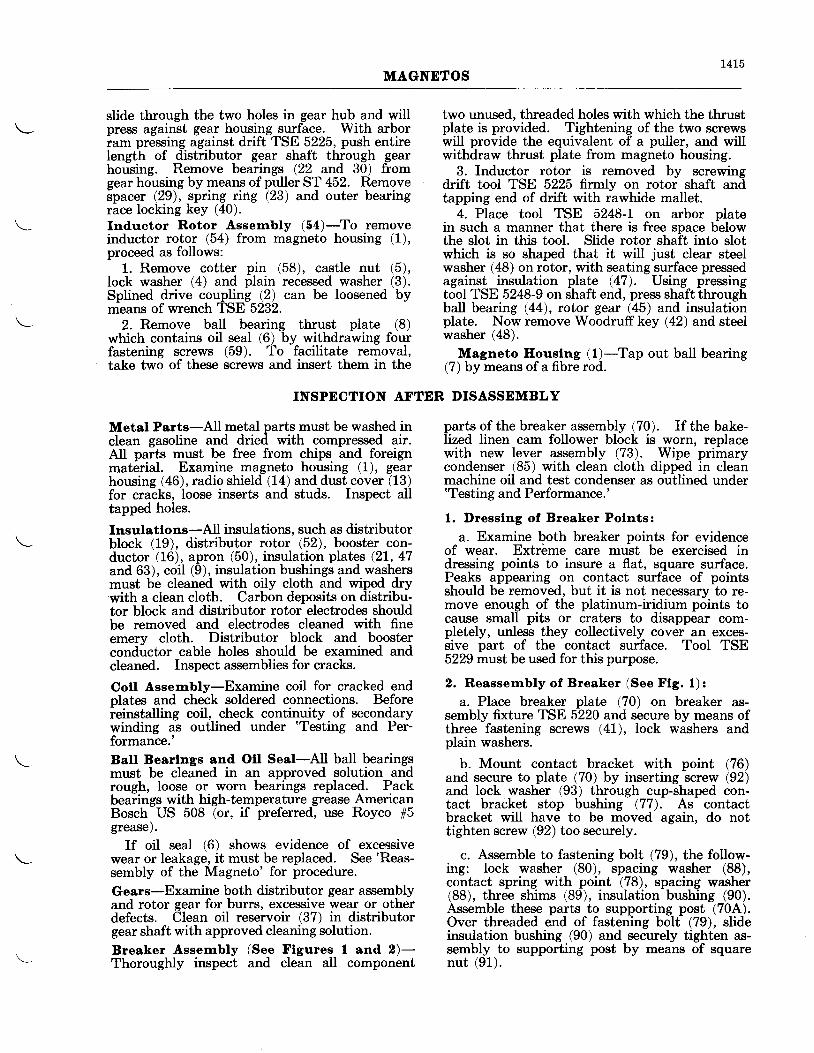
L4L5MAGNETOS
slide through the two holes in gear hub and willpress against gear housing surface. With arborram pressing against drift TSE 5225, push entireIength of distributor gear shaft through gearhousing. Remove bearings (22 and 30) fromgear housing by means of puller ST 452. Removespacer (29), spring riilg (23) and outer bearingrace locking key i40).Inductor Rotor Assernbly (ba)-To removeinductor rotor (54) from magneto housing (1),proceed as follows:
1. Remove cotter pin (58), castle nut (5),lock washer (4) and plain recessed washer (3).Splined drive coupling (2) can be loosened bymeans of wrench TSE 5232.
2. Remove ball bearing thrust plate (8)which contains oil seal (6) bv withdrawing fourfastening screws (59). To facilitate removal,take two of these screws and insert them in the
two unused, threaded holes with which the thrustplate is provided. Tightening of the two screwswill provide the equivalent of a puller, and willwithdraw thrust plate from magneto housing.
3. Inductor rotor is removed by screwingdrift tool TSE 5225 firmly on rotor shaft andtapping end of drift with rawhide mallet.
4. Place tool TSE 5248-t on arbor platein such a manner that there is free space belowthe slot in this tool. Slide rotor shaft into slotwhich is so shaped that it will just clear steelwasher (48) on rotor, with seating surface pressedagainst insulation plate (47). Using pressingtool TSE 5248-9 on shaft end, press shaftthroughball bearing (44), rotor gear (45) and insulationplate. Now remove Woodruff key (42) and steelwasher (48).
Magneto Eouslng (l)-Tap out ball bearing(7) bV means of a fibre rod.
INSPECTION AFTER DISASSEMBLY
Metal Parts-All metal parts must be washed inclean gasoline and dried with compressed air.AII parts must be free from chips and foreignmaterial. Examine magneto housing (1), gearhousing (46), radio shield (14) and dust cover (13)for cracks, Ioose inserts and studs. Inspect alltapped holes.
Insulatlons-All insulations, such as distributorblock (19), distributor rotor (52), booster con-ductor (16), apron (50), insulation plates (2L, 47and 63), coil (9), insulation bushings and washersmust be cleaned with oily cloth and wiped drywith a clean cloth. Carbon deposits on distribu-tor block and distributor rotor electrodes shouldbe removed and electrodes cleaned with fineemery cloth. Distributor block and boosterconductor cable holes should be examined andcleaned. Inspect assemblies for cracks.
Coll Assembly-Examine coil for cracked endplates and check soldered connections. Beforeieinstalling coil, check continuity of secondarywinding as outlined under 'Testing and Per-formance.'Ball Bearlngs and Otl Seal-All ball bearingsmust be cleaned in an approved solution andrough, loose or worn bearings replaced. Packbearings with high-temperature grease AmericanBosch US 508 (or, if preferred, use Royco #5grease).
If oil seal (6) shows evidence of excessivewear or leakage, it must be replaced. See 'Reas-
sembly of the Magneto' for procedure.
Gears-Examine both distributor gear assemblyand rotor gear for butrs, excessive wear or otherdefects. Clean oil reservoir (37) in distributorgear shaft with approved cleaning solution.
Breaker Assernbly (See Flgures I and 2)-ThorougNy inspect and clean all component
parts of the breaker assembly (70). If the bake-lized linen cam follower block is worn, replacewith new lever assembly (73). Wipe primarycondenser (85) with clean cloth dipped in cleanmachine oil and test condenser as outlined under'Testing and Performance.'
1. I)resslng of Breaker Polnts:
a. Examine both breaker points for evidenceof wear. Extrbme care must be exercised indressing points to insure a flat, square surface.Peaks appearing on contact surface of pointsshould be removed, but it is not necessary to re-move enough of the platinum-iridium points tocause small pits or craters to disappear com-pletely, unless they collectively cover an exces-sive part of the contact surface. TooI TSE5229 must be used for this purpose.
2. Reassernbly of Breaker (See Ftg. 1):a. Place breaker plate (70) on breaker as-
sembly fixture TSE 5220 and secure by means ofthree fastening screws (41), lock washers andplain washers.
b. Mount contact bracket with point (76)and secure to plate (70) by inserting screw (92)and lock washer (93) through cup-shaped con-tact bracket stop bushing (77). As contactbracket wiII have to be moved again, do nottighten screw (92) too securely.
c. Assemble to fastening bolt (79), the follow-ing: Iock washer (80), spacing washer (88),contact spring with point (78), spacing washer(88), three shims (89), insulation bushing (90).Assemble these parts to supporting post (70A).Over threaded end of fastening bolt (79), slideinsulation bushing (90) and secwely tighten as-sembly to supporting post by means of squarenut (91).
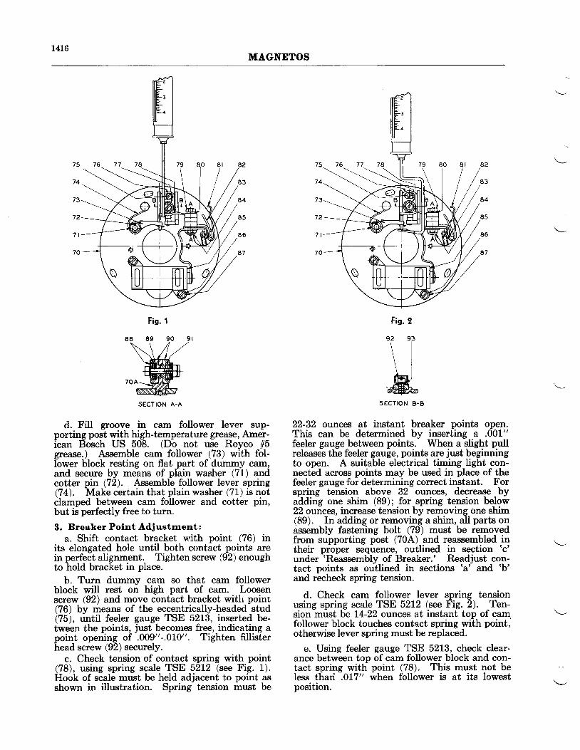
t4L6MAGNDTOS
Fig. t
SECTION A.A
d. FiU groove in cam follower lever sup-porting post with high-temperature grease, Amer-ican Bosch US 508. (Do not use Royco 15grease.) Assemble cam follower (73) with fol-lower block resting on flat part of dummy cam,and secure by means of plain washer (71) andcotter pin (72). Assemble follower lever spring(74). Make certain that plain washer (71) is notclamped between cam follower and cotter pin,but is perfectly free to turn.
3. Breaker Polnt Adiustrnent:a. Shift contact bracket with point (76) in
its elongated hole until both contact points arein perfect alignment. Tighten screw (92) enoughto hold bracket in place.
b. Turn dummy cam so that cam followerblock will rest on high part of cam. Loosenscrew (92) and move contact bracket with point(76) bv means of the eccentrically-headed stud(75), until feeler gauge TSE 5213, inserted be-tween the points, just becomes free, indicating apoint opening of .009"-.01,0". Tighten fillisterhead screw (92) securely.
c. Check tension of contact spring with point(78), using spring scale TSE 52L2 (se Fig. 1).Hook of scale must be held adjacent to point asshown in illustration. Spring tension must be
SECTION B.B
22-32 ounces at instant breaker points open.This can be determined by inserting a .001"feeler gauge between points. When a slight pullreleases the feeler gauge, points are just beginningto open. A suitable electrical timing light con-nected across points may be used in place of thefeeler gauge for determining correct instant. Forspring tension above 32 ounces, decrease byadding one shim (89); for spring tension below22 ounces, increase tension by removing one shim(89). In adding or removing a shim, all parts onassembly fastening bolt (79) must be removedfrom supporting post (70A) and reassembled intheir proper sequence, outlined in section 'c'
under 'Reassembly of Breaker.' Readjust con-tact points as outlined in sections 'a' and 'b'
and recheck spring tension.
d. Check cam follower lever spring tensionusing spring scale TSE 5212 (see Fig. 2). Ten-sion must be t4-22 ounces at instant top of cam.follower block touches contact spring with point,otherwise lever spring must be replaced.
e. Using feeler gauge TSE 5213, check clear-ance between top of cam follower block and con-tact spring with point (78). This must not beIess thari .017" when follower is at its lowestposition.
Fig. 2
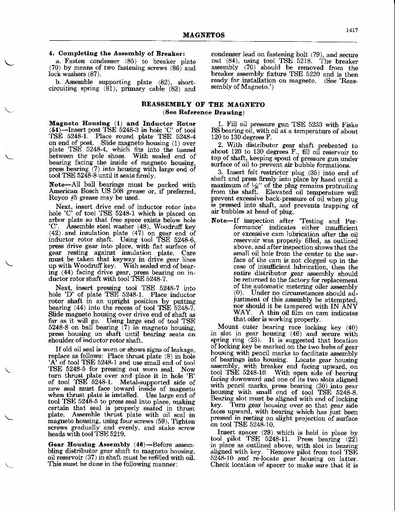
r4L7MAGNDTOS
4. Corrpletlng the Assernbly of Breaker:a. Fasten condenser (85) to breaker plate
(70) by means of two fastening screws (86) andlock washers (87).
b. Assemble supporting plate (82), short-circuiting spring (81), primary cable (83) and
condenser lead on fastening bolt (79), and securenut (84), using tool TSE 5218. The breakerassembly (70) should be removed from thebreaker assembly fixture TSE 5220 and is thenready for ir?stallation on magneto. (See 'Reas-sembly of Magneto.')
REASSEMBLY OF TEE MAGNETO(See Reference Drawlng)
Magneto Eouslng (1) and Inductor Rotor(54)-Insert post TSE 5248-3 in hole 'C' of tool'fSE 5248-l-. Place round plate TSE 5248-4on end of post. Slide magneto housing (1) overplate TSE 5248-4, which fits into the tunnelbetween the pole shoes. With sealed end ofbearing facing the insjde of magneto housing,press bearing (7) into housing with large end oftool TSE 5248-8 until it seats firmly.Note-All baII bearings must be packed withAmerican Bosch US 508 grease or, if preferred,Royco 15 grease may be used.
Next, insert drive end of inductor rotor intohole 'C' of tool TSE 5248-1 which is placed onarbor plate so that free space exists b-elow hole'C'. Assemble steel washer (48), Woodruff key(42) and insulation plate (47) on gear end ofinductor rotor shaft. Using tool TSE 5248-6,press drive gear into place, with flat surface ofgear resting against insulation plate. Caremust be taken that keyway in drive gear linesup with Woodruff key. With sealed end of bear-in9 G4) facing 4rive gear, press bearing on in-ductor rotor shaft with tool TSE 5248-7.
Next, insert pressing tool TSE 5248-7 tntohole 'D' of plate TSE 5248-1. Place inductorrotor shaft in an upright position by puttingbearing (44) into the recess of tool TSE 5248-7.Slide magneto housing over drive end of shaft asfar as it will go. Using large end of tool TSE5248-8 on ball bearing (7) in magneto housing,press housing on shaft until bearing seats onshoulder ofinductor rotor shaft.
If old oil seal is worn or shows signs of leakage,replace as follows: Place thrust plite (8) in h5le'A' of tool TSE 5248-l and use small end of toolTSE 5248-5 for pressing out worn seal. Nowturn thrust plate over and place it in hole 'B'of tool TSE 5248-1. Metal-supported side ofnew seal must face toward inside of magnetowhen thrust plate is irrstalled. Use large end oftool TSE 5248-5 to press seal into place, makingcertain that seal is properly seated iir thrusTplate. Assemble thrust plate with oil seal inmagneto hogsi4g, using four screws (59). Tightenscrews gradually and evenly, and stake screwheads with tool TSE 5219.
Gear Eouslng Asserrrbfv (48)-Before assem-bling distributor gear shaft to magneto housing,oil reservoir (37) in shaft must be refilled with oil.This must be done in the following manner:
1. Fill oil pressure gun TSE 5233 with FiskeBS bearing oil, with oil at a temperature of aboutL20 to 130 degrees F.
2. With distributor gear shaft preheated toabout L20 to 130 degrees F., fiIl oii reservoir totop of shaft, keeping spout of pressure gun undersurface of oil to prevent air bubble formations.
3. Insert felt restrictor plus (35) into end ofshaft and press firmly into plaie by hand until apaximym gf t4u" of-the plug remains protrudingfrom the shaft. Elevated oil tempeiature wiliprevent e-xcessive_ back-pressure of oil when plugis. pressed into shaft,- and prevents trapping oTair bubbles at head of plug.-Note-If inspection after 'Testing and Per-
formance' indicates either- insufficientor excessive cam lubrication after the oilreservoir was properly filled, as outlinedabove, and after inspection shows that thesmall oil hole from the center to the sur-face of the cam is not clossed up in thecase of in'sufficient lubricatlon. then theentire distributor gear assemblv shouldbe returned to the factorv for repiacementof the automatic metering oiler assembly(0). Under no circumstances should aci-justment_ gt tttis assembly be attempted,nor should it be tampered with IN ANYWAY. A thin oil film on cam indicatesthat oiler is working properly.
Mount outer bearing race locking key (40)in slot in gear housing (46) and s-ecure i'ittrspring ring (23). It is suggested that locationof locking Fgy U" marked on the two hubs of gearhousing- with pencil marks to facilitate assemblyof bearings into housing. Locate gear housingassemb_ly, with breaker end facing upward, ontool TSE 5248-L0. With open siiie of bearingfaging downward and one of its two slots aligneiiwith. pencil _marks, press bearing (30) into gearhousing with small end of tool TSE 52[g-9.Bearing slot must, be aligned with end of locking\"y. Turn gear housing over so that gear sidefaces upward, with bearing which has iust beenpressed in resting on slight projection of surfaceon tool TSE 5248-10.
Ipse{ spqggl (29) which is held in place bytool- pilot TSq 5248-11. Press bearing (:2i)in- place as- oqtlined above, with slot in Fearingal.igned with key.
'Remove pilot from tool TSE
5248-10 and re-locate gear housing on latter.Check location of spacef to make sure that it is
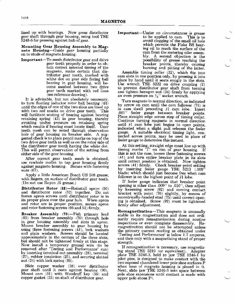
1418MAGNDTOS
Iined up with bearings. Now press distributorgear shaft through gear housing, using tool TSE5248-6 for pressing against hub ofgear.
Mountlng Gear Ilouslng Assexnbly to Mag-neto Iloust^ns-Guids gear housing partiallyon to studs of magneto.housing.Irnportant-To mesh distributor gear and drive
gear teeth properly in order to ob-tain correct internal timing of themagneto, make certain that dis-tributor gear tooth, marked withwhite dot on gear side facing ballbearing in gear housing, will be-come meshed between two drivegear teeth marked with red lines(see reference drawing).
It is advisable, but not absolutely necessary,to turn floating inductor rotor ball bearing (44)until the edges of one of the two slots are lined upwith two red marks on drive gear teeth. Thiswill facilitate seating of bearing against bearingretaining spring (43) in gear housing, therebyavoiding undue pressure on retaining springwhich results if bearing must locate itself. Gearteeth mesh can be noted through observationhole of gear housing on breaker side. A sug-gested check is to place pencil marks on top of thetwo drive gear teeth as well as on the rotor side ofthe distributor gear tooth having the white dot.This will permit observation of the setting fromeither side of the gear housing.
After correct gear teeth mesh is obtained,use rawhide mallet to tap gear housing firmlyagainst magneto housing. Secure with fasteningnuts (67).
Apply a little American Bosch US 508 grease,with fingers, on surface of distributor gear teeth.(Do not use Royco 15 grease.)
Dlstrlbutor Rotor (52)-Reinstall apron (50)and distributor rotor (52) together. Do notfasten apron screws until distributor rotor is inits proper place over the gear hub. When apronand rotor are in proper position, secure apronand rotor fastening screws (66 and 51) firmly.
Breaker Assernbly (70)-Fish primary lead(83) from breaker assembly (70) through holein gear housing assembly and slots in apron.Mount breaker assembly to gear housing byusing three fastening screws (41), Iock washeisand plain washers. Screws should be locatedapproximately in the centers of the three slots,but should not be tightened firmly at this stage.Now install a temporary ground wire (to
-be
removed after 'Testing and Performance' run)by inserting terminal nut assembly (28), terminal(27), rubber insulation Q5), and securing slottednut t24) with lock spring 126).
Slide copper washer (38) over distributorgear shaft until it rests against bearing (30).Mount cam (31) with Woodruff key (36) andcopper gasket (33) on shaft ofdistributor gear.
Irnportant-Un4er no circumstances is greaseto be applied to cam. This- is toavoid clogging of the small oil holewhich permits the Fiske BS bear-ing oil to reach the surface of thecam from the metering oiler assem-bly. A second objeition is thepossibility of grease reaching thebreaker points, thereby causingburning and pitting of the latter.
Assemble timing collar (32), which fits intocam slots jn olre posjtion only, by pressing it intoplace by hand until it seats snugfu in tlie slots.Use wrench TSE 5232 on drive coupling (2)to prevent distributor gear shaft from turningand tighten hexagon nut (3!) firmly by applyingan even pressure on 14" socket wrench.
Turn magneto in normal direction, as indicatedby arrow on cam until the cam follower (78) isin cam dwell preceding #1 cam lobe. Insert.0_01" feele1 gagge between breaker points.Place straight edge across step of timing-collar.Continue turning magneto in normal directiongntil 11 cam lobe just begins to open points,indicated when a slight pull releasei the feelergauge. A suitable electrical timing light, con-nected acrossr points, may be used in-place offeeler gauge to determine this instant.
At this setting, straight edge must Iine up withtimi4g marks 'T' qr rim of gear housing. Ifthis is not the case, loosen three fastening screws(41) and turn entire.breaker plate in its slotsuntil correct-position is obtained. Now tightenscrews (41) firmly- Check breaker point settingby inserting feeleq gauge TSE 52Lg (.009tblade) which should just become free when camfollower is on the highest point of 11 lobe.
If feeler gauge indicates that breaker pointgpening is.other than .009" to .010", then adjustby loosening screw (92) and moving coniactbracket with point (76) slightly, by means ofeccentri!"ally-headed stud (75) until correct open-ing is obtained. Screw (92) must be tightenedfirmly after adjustment.
Re-rnagnetlzatlon-This magneto is unusuallystable in its magnetization and does not ordi-narily require remagnetization during routineinspections or even complete disassembly. Re-magnetization should not be attempted unlessthe primary current reading as obtained under'Testing and Performance' is below 1.7 amperes,and then only with a magnetizing stand of ploperstrength.
If remagne_tization is necessary, use magnetiz-ing stand TSE 5210 1or equivalent). Ailapterplate TSE 5246-2, held to law TSE 5246-t bypilot pins, is designed to make contact with th-etwo exposed chamfered lower pole shoe surfaces Pwhen base of magneto housing is placed in it.Next, slide jaw TSE 5246-3 into space betweenpole shoe extensions until contact ls made withupper pole shoes Pt.

1419MAGNETOS
It is essential to remagnetize magneto in thes€rme magnetic direction as originally done,otherwise a complete reversal of the permanentmagnets will be required, which might possiblybe beyond the strength of the particular magne-tizing stand available. Polarity can readily bedetermined by means of a compass. The southpole of the magneto should always be placedagainst the north pole of the magnetizing stand.Poles of stand TSE 52L0 are marked'N' and 'S'.
Apply two charges of four to five secondsduration each. It is suggested that inductorrotor be gtven a quarter turn between charges,in order to allow saturation of both magnets inturn. Now remove adapter'plate TSEr 5246-2fiom jaw TSE 5246-1, and reverse position ofjawTSE 5246-3 on magnetizing stand pole. Thiswill leave two straight jaw surfaces.
Place jaw TSE 5246-l against bottom ofmagneto housing underneath lower pole shoes P,and jaw TSE 5246-3 across upper pole shoe ex-tensions. With jaws held on same poles ofmagnetizirtg stand as before, apply two additionalcharses of four or five seconds duration. Thistime;f charging will be sufficient to allow mag-netizing current to build up to its full value forsaturation of the magnetic circuit.Completlng the Assernbly-Fasten insulationplate (63) and primary cable (83), held in placeby holding clip (53), to magneto housing withscrews (64). Mount coil (9) on pole shoe exten-sions, with high-tension electrode inserted intodistributor rotor. Place one plain washer underinsulation washer and insert both in spacebetween coil core and primary lead clamp as-sembly. Assemble lock washer, plain washer andinsulation bushing on screw (60), and fasten coilto pole shoe extensions, using short screw (61)with lock washer to tighten right-hand side ofcoil (as seen from drive end of magneto). Con-nect primary cable (83) to terminal block of coil.
ELECTRICAL TESTING
Condenser (85)-Test primary condenser (85)on a 500-volt Megger tester, with condenser pre-heated in an oven to 180-200 degrees F. Ifread-ing is 1 megohm or more, condenser is satisfactoryfor further use.
After providing distributor block with tem-porary test cables, install insulation plate (21)by hand. Mount distributor block to magnetoframe and secure with fastening nuts (65). Oheckair gap between electrodes ofdistributor rotor andelectrodes of distributor block with gauge TSE52L4.
At overhaul stage, with magneto being pre-pared for re-installation on engine, air gap be-tween electrodes should not be less than .015"nor greater than .060". If the latter conditionshould exist, distributor rotor must be replaced.In cases where visual inspection indicates thatdistributor block electrodes are also worn orburned excessively, both distributor rotor anddistributor block should be replaced.
At this time, magneto should be tested as out-Iined under'Electrical Testing and Performance'.
It is now assumed that tests are completed withtemporary ground wire and testing cables re-moved, distributor block reinstalled, and primarycable connected to terminal block of coil. Com-plete assembly as follows: Secure dust cover (13),including the booster assembly (16), to magnetohousing with screws (62). Fasten breaker cover(39) to gear housing with nuts (68). Assembleradio shield (14) and secure with screws (69 and55).
Note-Screws (69) holding shield to gear housingmust be tightened before screws (55)holding rihield to dust cover are inserted.
Mount radio shield elbow to radio shield.using screws (56).
Assemble drive coupling (2), plain recessedwasher (3), lock washer (4), castle nut (5), andcotter pin (58) to the drive end ofinductor rotorshaft. . Magneto is now ready for re-installationon engrne.
AND PERFORMANCE
sensitive voltmeter of suitable range for batterybeing used (see sketch).
A definite voltmeter reading must be obtainedwhich will be somewhat less than the battervvoltage, depending on sensitivity of voltmetei.If continuity of secondary winding is checkedwith an ohm-meter, resistance should be 3900 to4300 ohms.
Final test of coil must be made during actualtest run of magneto as outlined in latter part ofthis chapter.Test Runs-Attach pulley TSE 5250 to rotorshaft and mount magneto on a suitable test standwhich is provided with adiustable test gaps ST260. Test stand must have a variable speedrange up to 3000 magneto R.P.M.
Connect high-tension cables to test gaps withpointed, three-electrode test gaps set at 9 mm (seesketch).
T E R M I N A L
V O L T M E T E R
Cott (0)-Check continuity of secondary windingby connecting coil in series with battery and
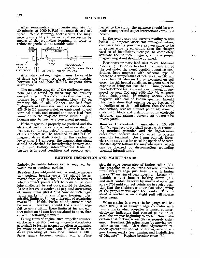
1420MAGNETOS
H I G HTENSIONELECTRODE
SPARK GAPA S R E Q U I R E D
GROUND ELECTRODEMAINTAIN SHARP POINTS
After remagnetization, operate magneto for30 minutes at 2000 R.P.M. magneto drive shaftspeed. While running, short-circuit the mag-neto primary fifty times in rapid succession bymeans of the grounding terminal, in order toreduce rnagnetization to a stable value.
nected to the stand, the magneto should be cor-rectly remagnetized as per instructions containedherein.
In the event that the current reading is stillb"l9* 1.7_ amperes after this remagnelization,coil tests having previously proven same to bein proper working _condition, then the chargerused is of insufficient strength to completelysaturate the 'Alnico'
14qgne!s, and the propermagnetizing stand should be obtained.
Reconnect primary lead (83) to coil terminalblock (11). In order to check the insulation ofthe coil under the worst possible operatin'g con-ditions, heat magneto with refleCtor type ofheater to a temperature of not less than 165 normore than 190 degrees F., as measured on coilcore. In this heated condition, magneto'must be'capable of firing not less than 10 mm, pointed,three-electrode test gaps without missing, at anys_peed between 200 ana 3OOO R.P.M.
"magnetir
drive shaft speed. If missing occurs, ctrecX.magneto with coil of known quality. Shouldthis check show that missing occurs because ofdifficulties other than coil failure, then the cableconnections, breaker contact point adjustment,distributor block and distribufor rotor-electrodeclearance, and primary cu::rent output must beinvestigated.
Booster Current-Run magneto at 100-200R.P.M. magneto drive shaft speed with ground-ing terminal grounded and the hish-lensioncable from booster tinit connected tb boosterassembly terminal. Use 7 mm pointed, three-electrode test gaps for checking spark of booster.Booster spark follows the magneto spark, whichcan be checked by disconnecting- groundingterminal intermittentlv.
After stablIization, magneto must be capableof firing the 9 mm test gaps without missingbetween L25 and 3000 R.P.M. magneto driveshaft speed.
The magnetic strength of the stationary mag-nets (M) is tested by measuring the primarycurrent output. To accomplish this, disconnectprimary lead (83) from terminal block (11) onbrimary side of coil. Connect one lead fromhigh-grade AC ammeter, such as Weston Model528 (0 to 2.5 ampere scale), or equivalent, to coilterminal block, and ground the other lead fromammeter to the magneto frame (stud on gearhousing may be used as a convenient ground).
If th€ magneto is properly magnetized and theelectrical performance of the coil is satisfactory(see test run for coil below), a minimum readingof 1.7 amperes will be obtained at 400 R.P.M.magneto drive shaft speed. If this reading islower than L.7 amperes, the magnetizing standshould be checked by investigating battery con-dition and battery interconnecting leads. Ifbattery is in good condition and properly con-
Lubrlcatlon-No lubrication is required be-tween major overhaul periods.
Breaker Assembly-At regular routine inspec-tion periods, breaker cover (39) should be re-moved from gear housing (46), and the instant atwhich contact points start to open on ffl camIobe (indicated by red dot), should be checked.At this instant, a straight edge placed across stepof timing collar (32) should coincide with regis-tering marks 'T' on rim of gear housing. Per-missible limits are/n" on either side of registeringmarks 'T'. If this checks, no adjustments needbe made. However, should the straight edgefail to come within these limits at instant con-tact points on 11 cam lobe are about to open, thencorrect in following manner:
Facing front of engine, turn propeller counter-clockwise (thereby causing magneto distributorgear shaft to turn in normal direction as indicatedby arrow on cam) until cam follower is in camdwell preceding #1 cam lobe. Insert a .001"feeler gauge between contact points. Place
ROUTINE INSPDCTION AND MAINTENANCE
straight e4_ge across step of timing collar (32).Jar propeller in a counter-clockwise directionuntr_l slrqSht edge just lines up with timingmarks 'T' on rim of gear housing. Loosen ad--jr:stable- contact _bracket, locking screw (92),and shift contact bracket by means of eccentr-iiscrew (75) lrntilcontact points are in such a posi-tion- that the_ slightest counter-clockwise jairingof the propeller will open the points. This in--stant is reached when a slight pull will releasefeeler gauge.
When setting is correct, feeler gauge will be-come free just as straight edge coincides withtiming marks when propeller is turned counter-clockwise, indicating that contact points on filcam lobe are just beginning to open.- Now makecertain that locl<ing screw (92) is securely tight-ened. Re-check this adjustment by moving pro-peller as outlined. Aft-er final adjustmentf re-check synchronization of both magnetos to en-gine timing marks (see 'Timing and Installationof Magneto'). Replace breaker cover (39).
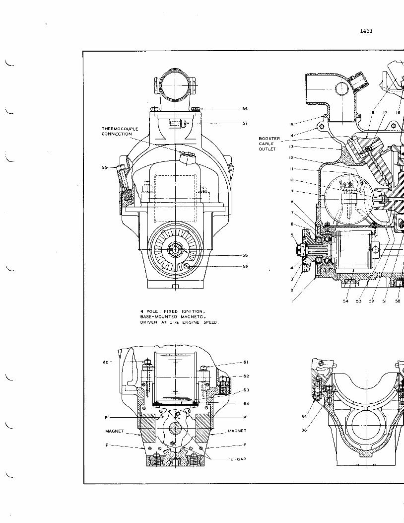
t427
THERMOCOUPLEC O N N E C T I O N
4
3
I
4 P O L E , F I X E D I G N I T I O N ,B A S E - M O U N T E D M A G N E T O ,D R I V E N A T 1 1 1 6 E N G I N E S P E E D .
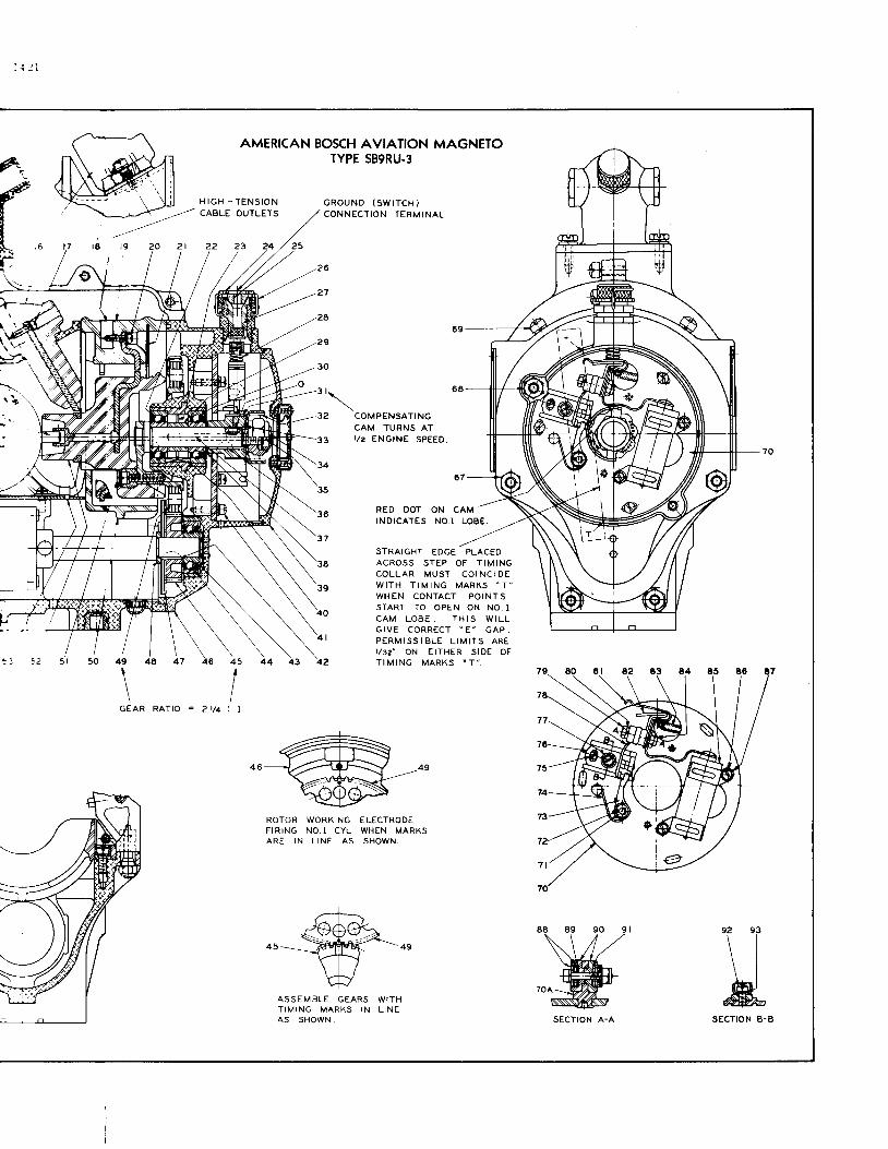
: i l I
AMERICAN BOSCH AVIATION MAGNETOTYPE SB9RU.3
H I G H - T E N S I O N G R O U N D ( S W I T C H )C O N N E C T I O N T E R M I N A L
COMPENSATINGCAM TURNS ATr /2 ENGINE SPEEO.
RED DOTINDICATES
ON CAMNO.I LOBE
46
STRAIGHT EDGE PLACEOA C R O S S S T E P O F T t M t N GC O L L A R M U S T C O I N C I D EW I T H T I M I N G M A R K S " T "
W H E N C O N T A C T P O I N T SSTART TO OPEN ON NO. IC A M L O B E . T H I S W I L LG I V E C O R R E C T " E " G A P .P E R M I S S I B L E L I M I T S A R EI /3e" ON EITHER SIDE OFT I M I N G M A R K S " T " .
\
GEARI
RATIO = 2 r/4
ROTOR WORKING ELECTRODEF I R I N G N O . I C Y L . W H E N M A R K SA R E I N L I N E A S S H O W N .
ASSEMBLE GEARS WITHT I M I N G M A R K S I N L I N EA S S H O W N .
\ l\ l&
ECTION B-
\--
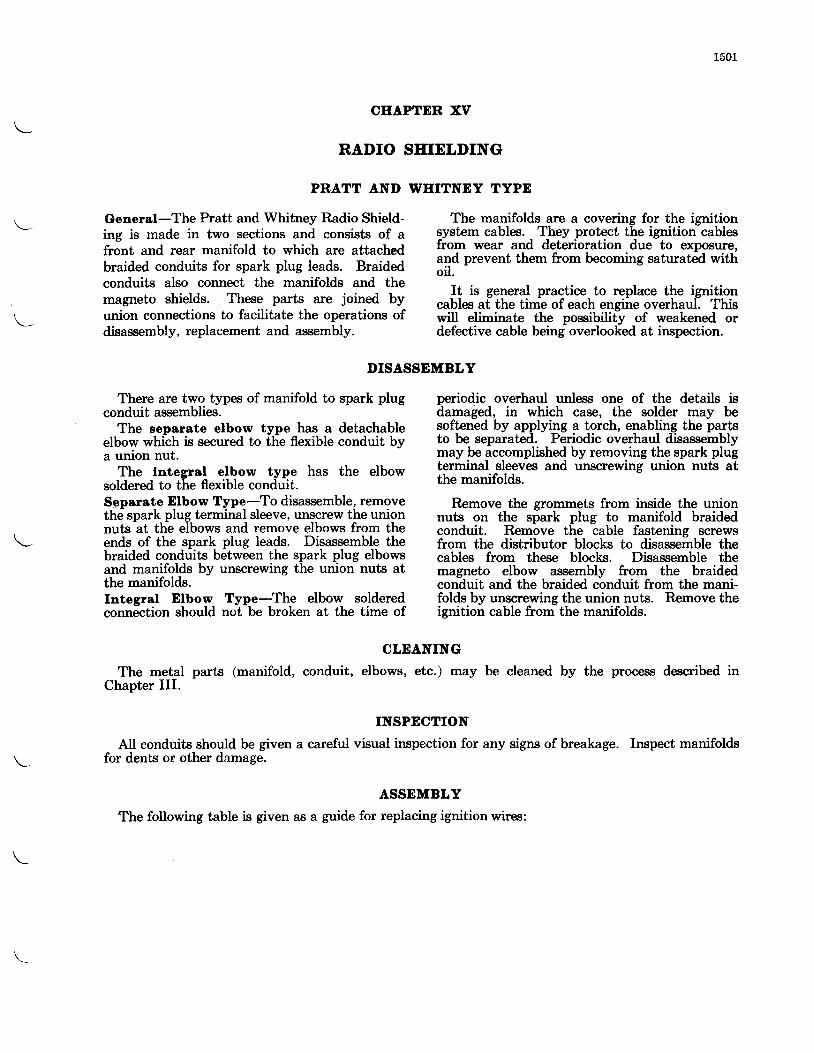
1501
General-The Pratt and Whitney Radio Shield-ing is made in two sections and consists of afront and rear manifold to which are attachedbraided conduits for spark plug leads. Braidedconduits also connect the manifolds and themagneto shields. These parts are joined byunion connections to facilitate the operations ofdisassembly, replacement and assembly.
CEAPTDR XV
RADIO SHIELDING
PRATT AND WHITNEY TYPE
DISASSEMBLY
The manifolds are a covering for the ignitionsystem cables. They protect the ignition cablesfrom wear and deterioration due to exposure,and prevent them from becoming saturated withoil.
It is general practice to replace the ignitioncables at the time of each engine overhaul. Thiswill eliminate the possibility of weakened ordefective cable being overlooked at inspection.
There are two types of manifold to spark plugconduit assemblies.
The separate elbow type has a detachableelbow which is secured to the flexible conduit bya union nut.
The tntegral elbow type has the elbowsoldered to the flexible conduit.Separate Elbow Type-To disassemble, removethe spark plug terminal sleeve, unscrew the unionnuts at the elbows and remove elbows from theends of the spark plug leads. Disassemble thebraided conduits between the spark plug elbowsand manifolds by unscrewing the union nuts atthe manifolds.Integral Elbow Type-The elbow solderedconnection should not be broken at the time of
periodic overhaul unless one of the details isdamaged, in which case, the solder may besoftened by applying a torch, enabling the partsto be separated. Periodic overhaul disassemblymay be accomplished by removing the spark plugterminal sleeves and unscrewing union nuts atthe manifolds.
Remove the grommets from inside the unionnuts on the spark plug to manifold braidedconduit. Remove the cable fastening screwsfrom the distributor blocks to disassemble thecables from these blocks. Disassemble themagneto elbow assembly from the braidedconduit and the braided conduit from the mani-folds by unscrewing the union nuts. Remove theignition cable from the manifolds.
CLEANING
The metal parts (manifold, conduit, elbows, etc.) may be cleaned by the process described inChapter III.
INSPECTION
AII conduits should be given a careful visual inspection for any signs of breakage. Inspect manifoldsfor dents or other damage.
ASSEMBLY
The following table is given as a guide for replacing ignition wires:
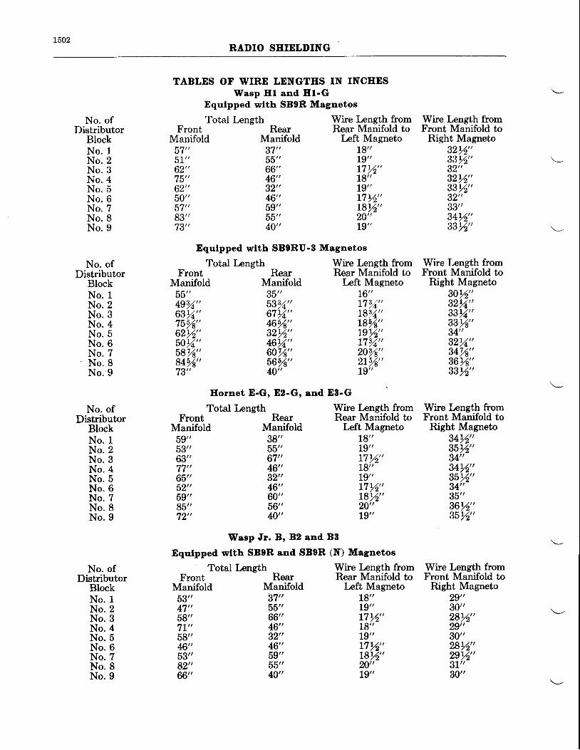
L502RADIO SEIELDING
TABLES OF WIRE LENGTES IN INCEESWasp Hl and El-G
Equlpped wtth SBOR Magnetos
No. ofDistributor
BlockNo. 1N o . 2N o . 3N o . 4N o . 5N o . 6N o . 7N o . 8N o . 9
No. ofDistributor
BIockNo. 1N o . 2N o . 3N o . 4N o . 5N o . 6No. 7N o . 8N o . 9
No. ofDistributor
BlockNo. 1N o . 2N o . 3N o . 4N o . 5N o . 6N o . 7N o . 8N o . 9
No. ofDistributor
BlockNo. 1N o . 2N o . 3N o . 4N o . 5N o . 6N o . 7N o . 8N o . 9
FrontManifold
o t51"62"75"62"50"D t '
83"73"
FrontManifold
oo49s2"63r2"7554"62%"5012,,58V8"8454"73"
RearManifold37"55"66"46"32"46"59"55"40"
RearManifold35"5314"67r2"4654"32Y2"4611"60V8"5654"40,,
Wire Length fromRear Manifold to
Left MagnetoT6"1714"L8Y4"t854"Ls%"L732"2014"2ty6"L9"
Equlpped wtth SBORU-B Magnetos
Total Length
Total Length
Wire Length fromRear Manifold to
Left MagnetoL8"L9"t7rh,,18"L9"L7rk,,t8%"20,,L9"
Wire Length fromFront Manifold to
Right Magneto32%"3314"32"32%"33rh,,32"33"34rh,,33rh,,
Wire Length fromFront Manifold to
Right Magneto30rh,,32r2"33t2"33T4"34"32Ya"347A"36r4"33rh,,
Wire Length fromFront Manifold to
Right Magneto34Lh"35%"34"3412"35rh,,34"35"36%"35%"
Wire Length fromFront Manifold to
Right Magneto29"30"28rh,,29"30"28r2"29%"31"30"
Eornet D-G, Ez-G, and E8-G
Total LengthFront Rear
Manifold Manifold59" 38"53" 55"63" 67"77" 46"65" 32"52" 46"59" 60"85" 56"72" 40"
Total LengthFront Rear
Manifold Manifold53" 3'�1"47" 55"58" 66"'ll" 46"58" 32"46" 46"53" 59"92" 55"66" 40"
Wasp Jr. B' 82 and BB
Equtpped wlth SBOR and SB0R (N) Magnetos
Wire Length fromRear Manifold to
Left MagnetoL8"L9"17 %"18"19,,17Lh"Lgrk, '20"19"
Wire Length fromRear Manifold to
Left Magnetolg"19,,L7 %"18"79"r7 %"181h,,20"L9"
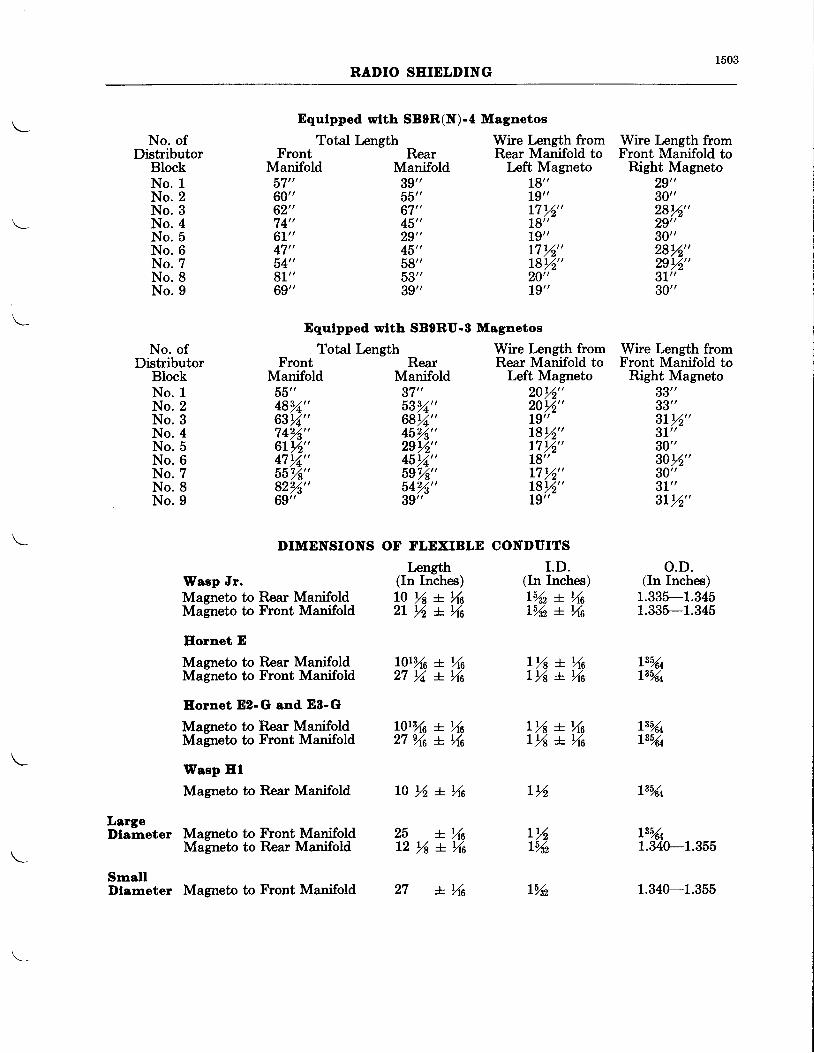
1503RADIO SEIDLDING
Equlpped wlth SBOR(N)-a Magnetos
No. ofDistributor
BlockNo. 1N o . 2N o . 3N o . 4N o . 5N o . 6N o . 7N o . 8N o . 9
No. ofDistributor
BlockNo. 1N o . 2N o . 3N o . 4N o . 5N o . 6N o . 7N o . 8N o . 9
Total LengthFront Rear
Manifold Manifold57" 39"60" 55"62" 67"'14" 45"6L" 29"47" 45"54" 59"81" 53"69" 39"
Wire Length from Wire Length fromRear Manifold to Front Manifold to
Left Magneto Right Magneto
FrontManifold
oD"4814"63r/+"74%"6trh,,47%"55%"82%"69"
DIMENSIONS
RearManifold37"5332"68Yr"45%"zgrh,,45%,"5e%"54%"39"
OT FLDXIBLE
Length(In Inches)l 0 % + % a2 l % * 4 6
l 0 r h + X 6
18"L9"L7rh,,18"L9"17 14"L8%"20"L9"
Wire Length fromRear Manifold to
Left Magneto20%"201h,,L9"L8rZ"17%"L8"L7rh,,r8rh,,t9"
CONDUITSI .D.
(In Inches)
29"30"28%"29"30"28%"29r2"3L"30"
Wire Length fromFront Manifold to
Right Magneto33"33"3t%"3L"30"30%"30"31"gLrh, ,
o.D.(In Inches)
1.335-1.3451.335-1.345
L3544
L\Y6L1.340-1.355
1.340-1.355
Equlpped wtth SBORU-B Magnetos
Total Length
Waep Jr.Magneto to Rear ManifoldMagneto to Front Manifold
Eornet E
Magneto to Rear ManifoldMagneto to Front Manifold
Eornet D2-G ond E8-G
Mameto to Rear ManifoldMagneto to Front Manifold
Waep Hl
Magneto to Rear Manifold
Magneto to Front ManifoldMagneto to Rear Manifold
Magneto to Front Manifold
lYn + \sL%z + %a
l3%4135/u
Lrl + YnLr/a + %a
L0ryr6 + Yt627 Ya *. Xa
Ls%4L3%4
L % + X tL % + % t
L0r%6 + N62 7 % a * \ a
LargeDlameter
SmallDlameter
r%
r %L%z
2 5 + X 6L2 rl * Yra
L N 6 lYrz
1504RADIO SHIELDING
For information pertaining to any ignitioncable not in the following approved list, consultthe Service Department of Pratt and WhitneyAircraft.
Belden Manufacturing ConrpanyChicago, Illinois,
General Cable CorporationBuffalo, New York,
Packard Electric DivisionGeneral Motors CorporationWarren, Ohio,
Sterling Cable CorporationPort Huron, Michigan.
Mark ferrules consecutively from 1 ihrough 9with a suitable metal stamp. To reassemble,remove /2" insulation from the end of each lenglhof cable,-being careful not to cut any of thestrands. Sepaiate the strands of wire and bendthem back
-along the insulation' Install each
ferrule on its corresponding number ignitioncable and secure it with a crimping tool.
String the cables through the manifold and intheir pr-oper outlet holes, maintaining the neces-
sary length of cable from manifold to magneto.Asiembl6 the spark plug conduits and fasten withunion nuts using a grommet in each union.Install the elbows and terminal sleeves, andsolder the ends of the wires to the terminalsleeves.
Assemble the conduits from manifolds tomagnetos.
Using some form of standard electrical test,make sure that the number on each ferrule cor-resnonds with the number of the cylinder towhich the cable runs. Then attach the wire tothe magneto distributor blocks according to thewiring
-diagram tFig. 611). After assembly of
the niagneto block, again check with some formof standard electrical test to make sure that thewires are in position for proper firing order.
AII joints should be carefully inspected afterassembly to see that they are snug and that thereare no vibrating contacts. No external solderingshould be attempted while the ignition cable isin the shield, as the heat necessary to make thesoldered joint is detrimental to the insulation ofthe cable, and may injure it to the extent thatthis point will be the first to break down.
REPLACING ONE IGNITION CABLE
Determine which cable is defective by arecognized electrical test. Disassemble the con-nection and elbow from the end of the sparkplug lead and remove the spark plug lead conduitLy uncoupling the union nut. Remove the wirefrom the distributor block. Loosen the couplingnut on the conduit from the manifold to magnetoand slip the conduit back towards the distributorblock.
Solder the new cable to the old cable at thespark plug end. Dust the new cable with talcoi soapstone to prevent seizing or friction. Pullthe old cable out, at the same time feeding thenew cable in at the manifold. It is necessary toperform this operation carefully so as not toinjure the protective coating on the cable. Whenthe new wire has been pulled through far enough,cut it off to the proper length on each end.Reassemble the conduits, elbow and spark plugterminal sleeve connection, and solder the wireto the connection.
Termlnal Sleeves-Particular care should beexercised when installing the terminal sleeveson the ignition wire.' Cut only enough insula-tion from the conductor to permit the correctlength of wire to extend through the wire outlet.Th6 insulation must bear firmli against the brassdisc on the inside end of the sleeve. The endsof the ignition wires which are constructed witha layer-of cotton under the lacquered surfaceshould be dipped in an insulating varnish toabout y8" ;;d permitted to dry before theterminal sleeves are applied to the wire. Thistreatment prevents th6 layer of cotton fromacting as a *ick should moisture find its way inlothe a-ssembly. When installing the terminal inthe plug it- should be wiped- perfectly clean,and aftel that not touched by the fingers as oil,acid, dirt, etc., will promote flash-over, causedeterioration and eventual failure of the sleeve.The repeated installation of dirty sleeves in aspark plug results in contaminating t-he micainsulation-on the inside of the barrel, whicheventually will cause faulty operation.
1601
CEAPTER XVI
AUTOMATIC OIL TEMPDRATURE CONTROL
DESCRIPTION
A thermostatic oil temperature regulator isnow included as standard equipment to be in-corporated in the oil system of any airplane. Thisdevice automatically regulates the temperatureof the oil entering the engine to a predeterminedsetting, thus obviating the use of radiator shut-ters or other means of controlling oil tempera-tures on a great number of installations. Where8" coolers, or larger, are utilized, congealing ofoilmav occur in the core of the cooler if the amountof dold air is greatly in excess of that required foroil cooling. Obviously, under these conditions itis necessary to have shutters or some other ac-ceptable means of controlling the amount of airalbwed to flow through the-cooler. It,also re-duces the warming up period to approximatelyone-half the time over installations not equippedwith this device.
When the oil is cold, the valve automaticallydirects the outlet oil from the engine to the bot-tom of the oil tank, in close proximity to the suc-tion line. Consequently the warm oil comingfrom the engine will be drawn into the suctionline feeding the oil pre$sure pump. This processcontinues until the oil entering the enginereaches the desired temperature; at which time,the automatic valve directs sufficient oil throughthe plane's external air cooler, thence to the topof the oil tank to maintain the desired inlettemperature.
The current type thermostatic oil temperaturecontrol assembly incorporates a check valve atthe point where the engine return oil line connectsto the unit. This valve prevents oil flowing fromthe tank into the scavenge system of the enginewhile the engine is not in operation.
Malntenance-The automatic oil temperaturecontrol unit normally requires no attention be-tween overhaul periods. The operating limitsof the unit cannot be altered except by replacingthe sylphon with one of a different calibration.
Dlsassembly-Remove the four nuts holdingthe two bodies together and separate. Disassem-ble nut from the end of the thermostatic unit andunscrew unit from body. Also remove the twonuts holding the check valve housing from thebody which houses the valve and separate.
The unit is now disassembled sufficiently forordinary inspection. If, however, it is intendedto replace any parts, remove the solder, nut andwaslier on end of unit. Disassemble valve and
vhlve guide. IJnscrew pin holding the checkvalve bushings and springs in place. The springs,bushing and valve may be then removed throughthe slot in the top ofthe check valve housing.
Cleanlng-Clean all parts with white furnace oil,or some suitable cleaner.
Inspeatlon-The automatic oil temperaturecontrol unit should be inspected at every regularengrne overhaul period by checking clearances inaccordance with clearance chart on Page 1603.Inspect the sylphon for any dents or cracks.Also inspect the seat of the check valve in casting.
Assembly-Assemble valve guide and valve tothe thermostatic unit. Fasten with washer andnut. Lock the nut with solder. Assemblegasket on each side of the valve guide and gasketon the threaded end of the thermostatic unit.Assemble unit in body and fasten with nut. In-stall body and fasten unit together with washersand nuts.
Then assemble the check valve assembly byinserting the springs, bushing and valve throughthe slot at the tbp of the casting and insert thepin holding them in place.
Therrnostatlo Unlt-It is good practice to testthe thermostatic control at the time of overhaulto determine whether or not the thermostatbellows are properly actuating the valves at thedesired temperature settings. Earlier units didnot have any temperature settings recorded onthe unit. Later units had the temperature set-tings on the thermostat stem only, while cunentunits now have the settings stamped on both thethermostat stem and data plate. In the case ofthe earfier units, the temperature settings willhave to be determined by checking the unit.
The temperature ranges and Part Nos. ofthermostats are as follows:
Part No.
181991p198181971640311435
Range
85o to 105'F.120o to 140'F.140o to 160'F.130o to 150'F.1 5 0 ' t o 1 7 0 ' F .
It should be noted that the above listed rangetemperatures are the temperatures at which thevalve starts to open, and at which it is fullyopened. The temperature at which the oil willstabilize is dependent upon the airplane installa-tion.
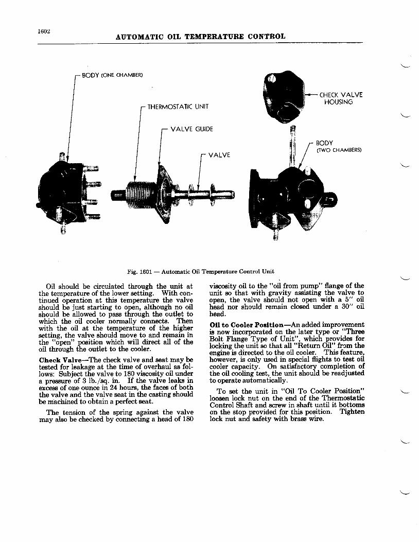
1602AUTOMATIC OIL TDMPERATURD CONTROL
BODY toNe cHAMBER)
THERMOSTATIC UNIT
VALVE GUIDE
CHECK VALVEHOUSING
(TWO CHAMBERS)
Fig. 1601 - Automatic Oil Temperature Control Unit
Oil should be circulated through the unit atthe temperature of the lower setting. With con-tinued operation at this temperature the valveshould be just starting to open, although no oilshould be allowed to pass through the outlet towhich the oil cooler normally connects. Thenwith the oil at the temperature of the highersetting, the valve should move to and remain inthe "oDen" position which will direct all of theoil thr6ugh the outlet to the cooler.
Cheak Volve-The check valve and seat may betested for leakage at the time of overhaul as fol-lows: Subject the valve to 180 viscosity oil undera Dressureof 3 lb./sq. in. If the valve leaks inex'cess of one ounce iri 2l hours, the faces of boththe valve and the valve seat in the casting shouldbe machined to obtain a perfect seat.
The tension of the spring against the valvemay also be checked by connecting a head of 180
viscosity oil to the "oil from pump" flange of theunit so that with gravity assisting the valve toopen, the valve should not open with a 5" oiltiead'nor should remain closeil under a 30" oilhead.
Oll to Cooler Poeltlon-An added improvementis now incorporated on the later type or "Three
Bolt Flange Type of lJnit", which provides forlocking the unit so that all "Return Oil" frcm theengine is dfuected to the oil cooler. This feature,however, is only used in special flights to test oilcooler capacity. On satisfactory completion ofthe oil cooling test, the unit should be readjustedto operate automatically.
To set the unit in "Oil To Cooler Position"loosen lock nut on the end of the ThermostaticControl Shaft and screw in shaft until it bottomson the stop provided for this position. Tightenlock nut and safety with brass wire.
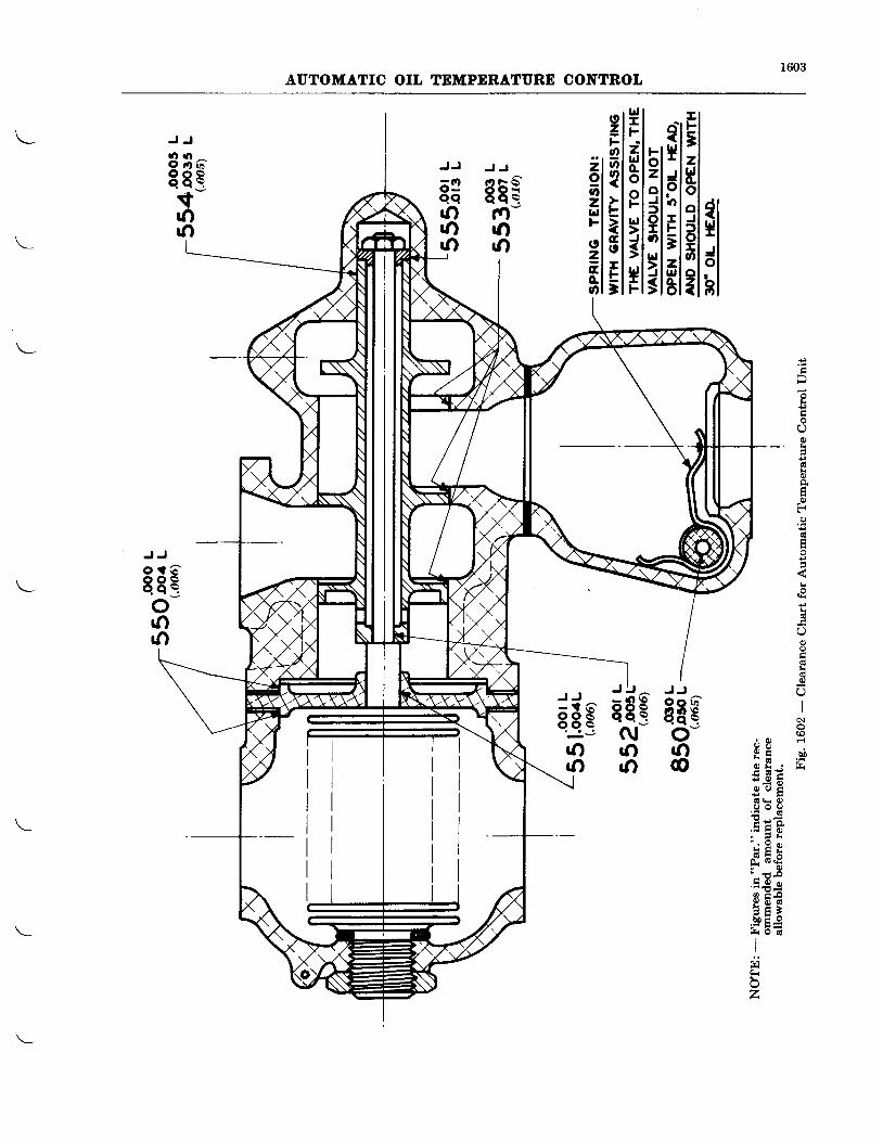
1603AUTOMATIC OIL TEMPDRATIIRD CONTROL
nllllllillhJJ
69qq()()'rl
J J
8 3 at 8 Bt-()rn
J J
sEg(Yl-(}()
k€
It
€I
0)a
F
,
o
k
O
N
b0
J JP o o G '5 E8E
ar-\ / r o. 4 \ 9 05 ' I CA - c g
rt I :. i+ _ 9 harE FF - t r6 l | Ov v v
E = E. - i 9
! F E6 x A
0 - 6 Ef ; -3
F 7 . -
.=..:g o
n E E! e o ( EE F }& E_e)i5- F=H 9 d
II
.:iFA
z
J t- . )EtN()()
J J
sgg'j-,
()()
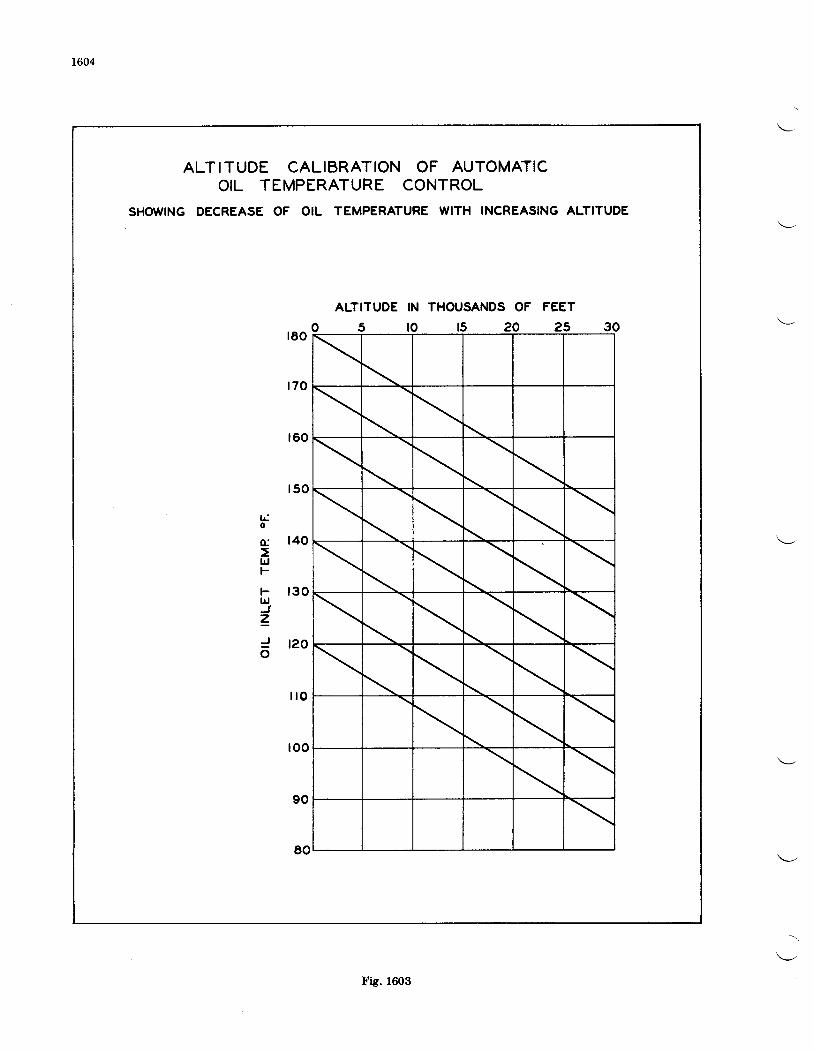
1604
ALT ITUDE CALIBRATION OF AUTOMATICOIL TEMPERATURE CONTROL
SHOWING DECREASE OF OIL TEMPERATURE WITH INCREASING ALTITUDE
AUTITUDE
5
THOUSANDS OF FEET
15 20 25
rdo
o:
lrjF
FlriJ.z_J
6
Fig. 1603
CEAPTER XVII
AUTOMATIC MIXTURE AND POWER CONTROL UNIT
THDORY
1701
air density control valve to maintain a densityequivalent to a predetermined altitude. Theuse of such an air density control valve necessi-tates the reduction of the power output of theengine at all times to the full throttle power atthe density altitude chosen.
Due to the fact that the metering characteris-tics of a carburetor are a function of the airdensity entering the carburetor, a simple methodof maintaining a constant metering characteristicis to maintain a constant density of this air. Todo this one must either employ an externalsupercharger to maintain sea level density or an
To avoid the use of an external supercharger,the air density control valve method was chosen.The particular application under considerationfor a-supercharged engine where it is desirableto restrict the maximum sea level power output,the two-fold purpose of the unit is readily compre-hensible in that a reduction in the density of theair entering the carburetor to the density alti-tude at which full throttle operation is permittednot only serves as an automatic throttle stop,but at the same time gives the desired constancyof carburetor metering. Carrying this thought
PRACTICAL APPLICATION
DESICN OF UNIT
AUTOMATIC MIXTURD CONTROL UNIT
still further, there is a density altitude at whichthe full throttle power is reduced to what isconsidered the normal cruising power of theengine. If the air entering the carburetor bereduced to this density, the cruising power out-put of the engine will then be maintained fromsea level to this altitude and the carburetormetering characteristics remain constantthroughout this range. In either of the abovecases, the carburetor throttle would be left inwide open position at all times.
To take care of cruising conditions, the unitmust reculate to one pressure; to take care ofconditiois requiring mbre power, the unit mustregulate to a second presfture and for cases ofemergency where it might be necessary to ex-ceed
-the rated power the air density control
valve must be held wide open. (For the cruisingcondition one mixture ratio from the carburetoris deeired, while for the higher power a secondmixture ratio is desired, and for the emergencyfull power condition, a third or still richer mixtureis required.)
The Automatic Mixture and Power ControlUnit is a device for maintaining the air enteringthe carburetor at a constant pres€lrre, and open-ine the correct number of jets in the carburetorto grve the desired mixture strength. A specialtype carburetor is supplied with this unit inoi8er to obtain the aulomatic mixture controlfeature. Bellows regulate the air pressure con-trol valve through an oil servo mechanism.
The unit is provided with a selector valve andthree positions are available. . The normalthrottle and manual mixture controls are pro-vided on this carburetor in case of any mal-functioning of the Automatic unit, and theAutomatic unit does not interfere with the normaluse of the throttle. It does, however, make itpossible to leave the throttle wide open for allnormal flyrng conditions except landing.
one is evacuated and spring loaded internally,and the other vented behind the venturis in thecarburetor, thereby being affected by the car-buretor air horn pressure. If the absolute pres-sure in the air horn is such that the evacuatedbellows is collapsed, the lever arm is drawn tothat side and, being fixed at the top, draws theneedle valve to that side. This action admits
EXPLAITATION OF TEE OPERATION OF AUTOMATIC MIXTIIRE CONTROL
The operation of the automatic mixture con-trol resuiator is shown diagrammatically on thefollowins pages. It will be seen from theseillustratilons that the principal operating partsof the regulator consisl of two bellows, a leverarm actuited by any movement of the bellowsand a needle valve directing oil to the twosides of the operating piston. Of the two bellows
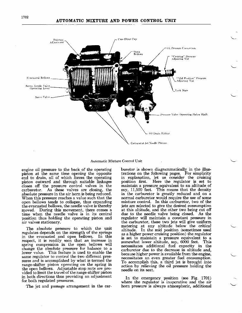
t702AUTOMATIC MIXTURE AND POWER CONTROL UNIT
Fulc runr- \d jus t r ren t
Case f i l ! i r rg Cap
L o c k N u t s
Evacuated Bel lows
Sen o Needlc Yalse()perat ing Lever
Serlo \ 'a lre
OpenBellows
Oi ! l ) rs iD F i t t inc
Carburetor Jet ),Ieedlc Pistonr
Oil Pressure Cott t tect iol t
"Cruisi Ig" PresstrreA d j u s t i n e N u t
" l l id Prsit iorr" Pressurcu-.tirg Nut
Prcssure Yalvo Operating Piston Shaft
Automatic Mixture Control Unit
engine oil pressure to the back of the operatingpiston at the same time opening the oppositeend to drain, all of which forces the operatingpiston outward and through suitable linkagescloses off the pressure control valves in thecarburetor. As these valves are closing, theabsolute pressure in the air horn is being reduced.When this pressure reaches a value such that theopen bellows tends to collapse, thus expandingthe evacuated bellows, the needle valve is therebymoved. During this movement, there comes atime when the needle valve is in its centralposition thus holding the operating piston andair valves stationary.
The absolute pressure to which the unitregulates depends on the strength of the springsin the evacuated and open bellows. In thisrespect, it is readily. seel that an- increase inspring compression in the open bellows willchange the absolute pressure for balance to alower value. This feature is used to enable thesame regulator to control the two different pres-sures and is accomplished by what is termed therange-shifter piston operating on the spring inthe open bellows. Adjustable stop nuts are pro-vided to limit the travel of the range-shifter pistonin both directions thus providing an adjustmentfor both regulated pressures.
The jet and passage arrangement in the car-
buretor is shown diagrammatically in the illus-trations on the following pages. For simplicityin explanation, let us consider the cruisingposition first. Here the regulator is set tomaintain a pressure equivalent to an altitude ofsay, 11,500 feet. This means that the densityin the carburetor is greatly reduced and on anormal carburetor would require the use of somemixture control. In this carburetor, two of thejets are selected to give the desired consumptionat this altitude, and the other two being cut offdue to the needle valve being closed. As theregulator will maintain a constant pressure inthe carburetor, these two jets will give uniformmetering at any altitude below the criticalaltitude. In the mid position (sometimes usedas a higher power cruising position) the regulatoris set to maintain a pressure equivalent to asomewhat lower altitude, say, 6000 feet. Thisnecessitates additional fuel capacity in thecarburetor due to the decrease in altitude and,because higher power is available from the engine,necessitates an even greater fuel consumption.To accomplish this, a third jet is brought intoaction by relieving the oil pressure holding theneedle on its seat.
In the emergency position (see Fig. 1701)where the regulator is inoperative and the airhorn pressure is always atmospheric, additional
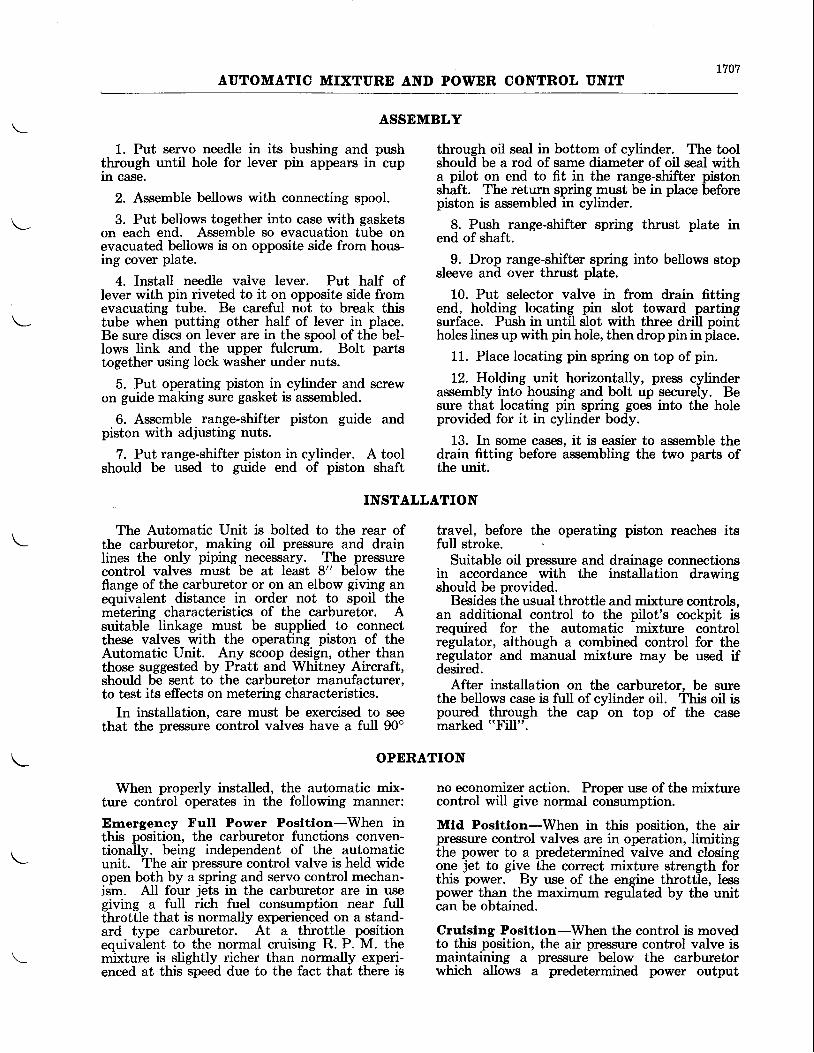
L707AUTOMATIC MIXTURE AND POWER CONTROL UNIT
1. Put servo needle in its bushing and pushthrough until hole for lever pin appears in cuprn case.
2. Assemble bellows with connecting spool.
3. Put bellows together into case with gasketson each end. Assemble so evacuation tube onevacuated bellows is on opposite side from hous-ing cover plate.
4. Install needle valve lever. Put half oflever with pin riveted to it on opposite side fromevacuating tube. Be careful not to break thistube when putting other half of lever in place.Be sure discs on lever are in the spool of the bel-lows link and the upper fulcrum. Bolt partstogether using lock washer under nuts.
5. Put operating piston in cylinder and screwon guide making sure gasket is assembled.
6. Assemble range-shifter piston guide andpiston with adjusting nuts.
7. Put range-shifter piston in cylinder. A toolshould be used to guide end of piston shaft
through oil seal in bottom of cylinder. The toolshould be a rod of same diameter of oil seal witha pilot on end to fit in the range-shifter pistonshaft. The return spring must be in place beforepiston is assembled in cylinder.
8. Push range-shifter spring thrust plate inend of shaft.
9. Drop range-shifter spring into bellows stopsleeve and over thrust plate.
10. Put selector valve in from drain fittingend, holding locating pin slot toward partingsurface. Push in until slot with three drill pointholes lines up with pin hole, then drop pin in place.
11. Place locating pin spring on top of pin.
12. Holding unit horizontally, press cylinderassembly into housing and bolt up securely. Besure that locating pin spring goes into the holeprovided for it in cylinder body.
13. In some cases, it is easier to assemble thedrain fitting before assembling the two parts ofthe unit.
ASSEMBLY
INSTALLATION
OPERATION
The Automatic Unit is bolted to the rear ofthe carburetor, making oil pressure and drainIines the only piping necessary. The pressurecontrol valves must be at least 8" below theflange of the carburetor or on an elbow giving anequivalent distance in order not to spoil them'etering characteristics of the carbureior. Asuitable linkage must be supplied to connectthese valves with the operating piston of theAutomatic Unit. Any scoop design, other thanthose suggested by Pratt and Whitney Aircraft,should be sent to the carburetor manufacturer,to test its effects on metering characteristics.
In installation, care must be exercised to seethat the pressure control valves have a full 90o
travel, before the operating piston reaches itsfull stroke.
Suitable oil pressure and drainage connectionsin accordance with the installation drawingshould be provided.
Besides the usual throttle and mixture controls,an additional control to the pilot's cockpit isrequired for the automatic mixture controlregulator, although a combined control for theregulator and manual mixture may be used ifdesired.
After installation on the carburetor, be surethe bellows case is full of cylinder oil. This oil ispoured through the cap on top of the casemarked "Fill".
When properly installed, the automatic mix-ture control operates in the following manner:
Errrergency Full Power Posltlon-When inthis position, the carburetor functions conven-tionally, being independent of the automaticunit. The air pressure control valve is held wideopen both by a spring and servo control mechan-ism. All four jets in the carburetor are in usegiving a full rich fuel consumption near fullthrottle that is normally experienced on a stand-ard type carburetor. At a throttle positionequivalent to the normal cruising R. P. M. themixture is slightly richer than n6rmally experi-enced at this speed due to the fact that there is
no economizer action. Proper use of the mixturecontrol will give normal consumption.
Mld Posltlon-When in this position, the airpressure control valves are in operation, limitingthe power to a predetermined valve and closingone jet to give the correct mixture strength forthis power. By use of the engine throttle, lesspower than the maximum regulated by the unitcan be obtained.
Crulslng Posltlon-When the control is movedto this position, the air pressure control valve ismaintaining a pressure below the carburetorwhich allows a predetermined power output
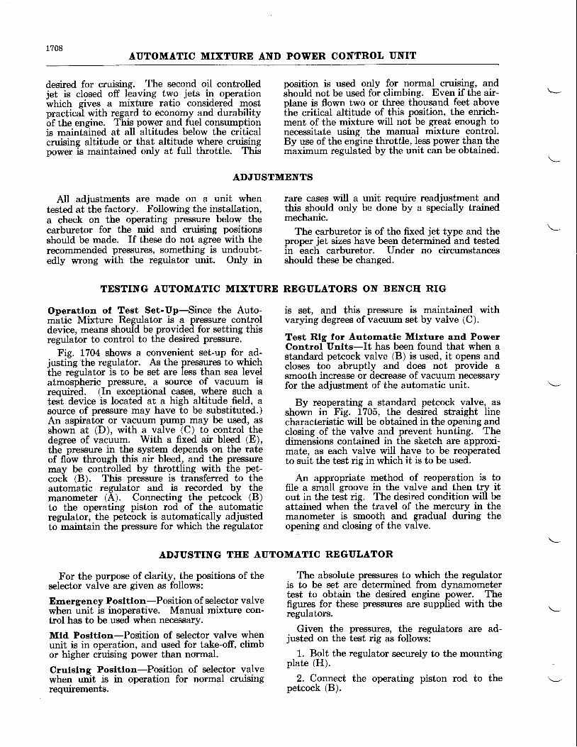
1708AUTOMATIC MIXTURE AND POWNR CONTROL UNIT
desired for cruising. The second oil controlledjet is closed off leaving two jets in operationwtrictr gives a mixture ratio considered mostpractical with regard to economy and durabilityof the engine. This power and fuel consumptionis maintained at aII altitudes below the criticalcruising altitude or that altitude where cruisingpower is maintained only at full throttle. This
position is used only for normal cruising, andstroutd not be used for climbing. Even if the air-plane is flown two or three thousand feet abovethe critical altitude of this position, the enrich-ment of the mixture will not be great enough tonecessitate using the manual mixture control.By use of the engine throttle, Iess power than them'aximum regulited by the unit cin be obtained.
ADJUSTMENTS
All adjustments are made on a unit whentested at the factory. Following the installation,a check on the operating pressure below thecarburetor for the mid and cruising positionsshould be made. If these do not agree with therecommended pressures, something is undoubt-edly wrong with the regulator unit. Only in
rare cases will a unit require readjustment andthis should only be done by a specially trainedmechanic.
The carburetor is of the fixed jet type and theproper jet sizes have been determined and testedin each carburetor. Under no circumstancesshould these be changed.
is set, and this pressure is maintained withvarying degrees of vacuum set by valve (C).
Test Rlg for Automatlc Mkture and PowerControl Unlts-It has been found that when astandard petcock valve (B) is used, it opens andcloses too abruptly and does not provide asmooth increase or decrease of vacuum necessaryfor the adjustment of the automatic unit.
By reoperating a standard petcock valve, asshown in Fig. 1705, the desired straight linecharacteristic will be obtained in the opening andclosing of the valve and prevent hunting. Thedimensions contained in the sketch are approxi-mate, as each valve will have to be reoperatedto suit the test rig in which it is to be used.
An appropriate method of reoperation is tofile a small groove in the valve and then try itout in the test rig. The desired condition will beattained when the travel of the mercury in themanometer is smooth and gradual during theopening and closing of the valve.
The absolute pressures to which the regulatoris to be set are determined from dynamometertest to obtain the desired engine power. Thefigures for these presriures are supplied with theregulators.
Given the presswes, the regulators are ad-justed on the test rig as follows:
1. BoIt the regulator securely to the mountingplate (H).
2. Connect the operating piston rod to thepetcock (B).
TESTING AUTOMATIC MIXTURE RDGULATORS ON BENCII RIG
Operatlon of Test Set-Up-Since the Auto---atic Mixture Regulator is- a pressure controldevice, means should be provided for setting thisregulator to control to the desired pressure.
Fig. 1704 shows a convenient set-up for ad-iustiig the regulator. As the pressures to whichthe regulator is to be set are less than sea levelatmospheric pressure, a source of vacuum isrequired. (In exceptional cases, where such atesl device is located at a high altitude field, asource of pressure may have to be substituted.)An aspirator or vacuum pump may be used, asshown at (D), with a valve (C) to control thedegree of vacuum. With a fixed air bleed (E),the pressure in the system depends on the rateof flow through this air bleed, and the pressuremay be controlled by throttling with the pet-cock (B). This pressure is transferred to theautomatic regulator and is recorded by themanometer (A). Connecting the petcock (B)to the operating piston rod of the automaticregulator, the petcock is automatically adjustedto-maintain the pressure for which the regulator
ADJUSTING TEE AUTOMATIC REGULATOR
For the purpose of clarity, the positions of theselector valve are given as follows:
Ernergency Posltlon-Position of selector valvewhen unit is inoperative. Manual mixture con-trol has to be used when necessary.
Mtd Posttlon-Position of selector valve whenunit is in operation, and used for take-off, climbor higher cruising power than normal
Crulslng Posltlon-Position of selector valvewhen unit is in operation for normal cruisingrequirements.
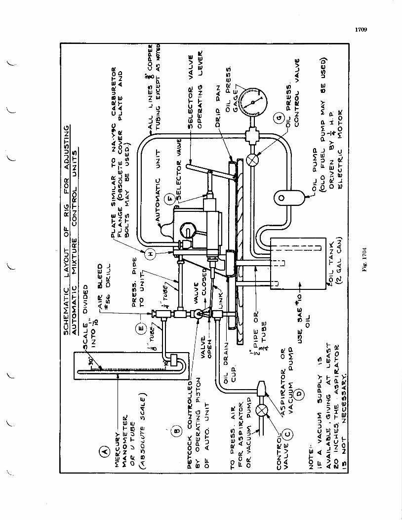
1709
F-
bi
tr,o
t: r f5-'nPo t -
o - r D u< ll,
i e 6 rde8 t
@;6
d 90 :
b k9 f fr D on o
aqro2
U,)1
oO sl q os uO F
ll,t,4u
U)oll,u&
J
6
z40
gdo
9U) ug rt
hu.lUxul
Iz@)F
rtooo\)
hoolu7)
J
(
Fzlr, (d)o u ,0 l F4 1U J
oui $d ) ai g a9 i r 3qdHj o v
zejo
A24t)olDUIt7
F0z
zu)
rJ
$l
{zFJ
o
zllloo
ul1s
\,p:-l!'
tzf
oF
l,o6yin!Jdo
rdur9{ / )t -<i \d d 8
))0/ooU)f,
otrJtudv(
rtQot-.7
oulo;6
u,)
t,o
nIzf
)g]-zoU
tr,g,lFxt
9\5ot-f{
(9zFof?o
uoL
Iu
Lo
Ftro
J
9F
:lrJIUo
oful1 ll r =
oulof
ot)o
t?ao)J\_-/
o u Ju r qe (
, oort- l N #jE
d
i k $o <e 2
< u ,: 0 ;l
3 , q Bt z lo i or ? $
do
0/ot-4vln
U w : .F > u ,'81 '9
2ado
AJ )
6 u
oE N \z n 6
n ; 5rJgP 8 5
zot-nI
F, g z7 _ lV
$ ou J f
3 i> Lo o
ou)JocFzI{uovIrlo
IU
so / Bllt UF Q l t rU r 3 \t l - jo f , 8< o ( or o s
v)
Ytlt)5
doFIJu,o
tz)
U
Eto|-)
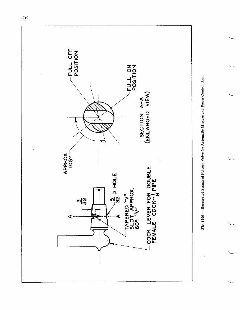
1710
k€
!0)B
0)lr
x
I
€
I
d
5
q)
h
axx
L
x
rrJ
F-
bb
"et ;68F t rU <U J Jq zc,
lrlJo? r,r)< o-" dtr-lo9 tr r .<,- l)f i o5 ulrJJ U J
Jr <U >o l dL , L
z zo o, Ft o
f oI L (L
x. O> tt t^ [ Li l< i( r , JH 5 oz J oF o o
lrlJoI
ci' l$
t zo 9J tJ q) oI L ( L
\
o|oo
xo&,o.(L
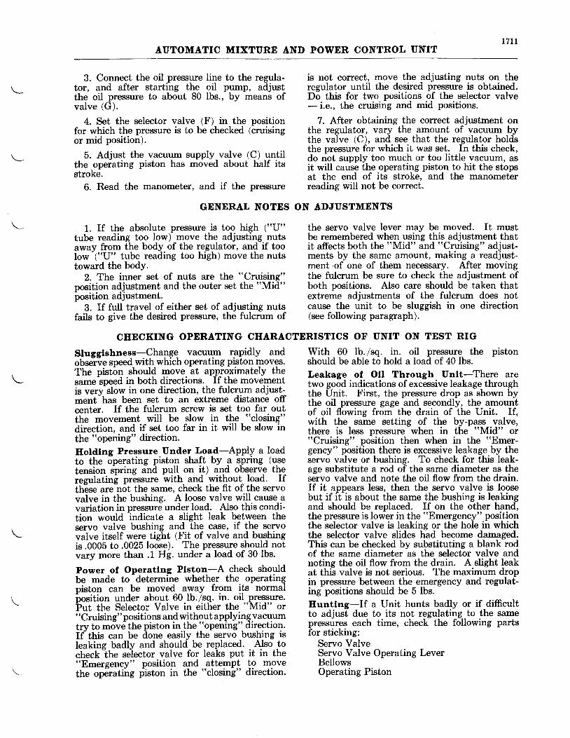
171 IAUTOMATIC MIXTURE AND POWER CONTROL UNIT
3. Connect the oil pressure line to the regula-tor, and after starting the oil pump, adjustthe oil presriure to about 80 lbs., by means ofvalve (G).
4. Set the selector valve (F) in the positionfor which the pressure is to be checked (cruisingor mid position).
5. Adjust the vacuum supply valve (C) untilthe operating piston has moved about half itsstroke.
6. Read the manometer, and if the pressure
is not correct, move the adjusting nuts on theregulator until the desired pressure is obtained.Do this for two positions of the selector valve- i.e., the cruising and mid positions.
7. After obtaining the correct adjustment onthe regulator, vary the amount of vacuum bythe valve (C), and see that the regulator holdsthe pressure for which it was set. In this check,do not supply too much or too little vacuum, asit will cause the operating piston to hit the stopsat the end of its stroke, and the manometerreading will not be correct.
GENERAL NOTES ON ADJUSTMENTS
1. If the absolute pressure is too high ("U"tube reading too low) move the adjusting nutsaway from the body of the regulator, and if toolow
-("(J" tube reading too high) move the nuts
toward the bodY.2. The inner set of nuts are the "Cruising"
position adjustment and the outer set the "Mid"
iosition adjustment.3. If full travel of either set of adjusting nuts
fails to give the desired pressure, the fulcrum of
the servo valve lever may be moved. It mustbe remembered when using this adjustment thatit affects both the rrMid" and "Cruising" adjust-ments by the same amount, making a readjust-ment.of one of them necessary. After movingthe fulcrum be sure to check the adjustment ofboth positions. Also care should be taken thatextreme adjustments of the fulcrum does notcause the unit to be sluggish in one direction(see following paragraph).
CIIECKING OPERATING CIIARACTERISTICS OF UNIT ON TEST RIG
Slugglshness-Change vacuum rapidly andobselve speed with which operating piston moves.The piston should move at approximately thesame speed in both directions. If the movementis ver5rslow in one direction, the fulcrum adjust--ment-has been set to an extreme distance offcenter. If the fulcrum screw is set too far outthe movement will be slow in the "closing"
direction, and if set too far in it will be slow inthe "opening" direction.
Hotdtnc Pressure Under Load-Apply a loadto the operating piston shaft by a spring (usetension spring and pull on it) and observe thereeulatins pressure with and without load. Ifth"ese are not the same, check the fit of the servovalve in the bushing. A loose valve will cause avariation in pressure under load. Also this condi-tion would indicate a slight leak between theservo valve bushing and the case, if the servovalve itself were tight (Fit of valve and bgqhittgis.0005 to.0025 loose). The pressure should notvary more than .1 Hg. under a load of 30 lbs.
Power of Operatlng Plston-A check shouldbe made to
-determine whether the operating
piston can be moved away from its normalbosition under about 60 lb./sq. in. oil pressiure.Put the Selectoi Valve in either the "Mid" or"Cruising" positions and without applyingvacuumtrv to move the piston in the "opening" direction.tf ttris can be ilone easily the servo bushing isleaking badly and should-be-replaced. . Also tocheck-the selector valve for leaks put it in the"Emergency" position and attempt !o movethe operatiirg plston in the "closing" direction.
With 60 lb./sq. in. oil pressure the pistonshould be able to hold a load of 40 lbs.Leakage of Oll Through Untt-There aretwo good indicatlons of excessive leakage throughthe Unit. First, the pressure drop as shown bythe oil pressure gage and secondly, the amountof oil flowing from the drain of the Unit. If,with the same setting of the by-pass valve,there is less pressure when in the "Mid" or"Cruising" position then when in the "Emer-gency" position there is excessive leakage by theservo valve or bushing. To check for this leak-age substitute a rod of the same diameter as theservo valve and note the oil flow from the drain.If it appears less, then the servo valve is loosebut if it is about the same the bushing is leakingand should be replaced. If on the other hand,the pressure is lower in the "Emergency" positionthe selector valve is leaking or the hole in whichthe selector valve slides had become damaged.This can be checked by substituting a blank rodof the same diameter as the selector valve andnoting the oil flow from the drain. A slight leakat this valve is not serious. The maximum dropin pressure between the emergency and regulat-ing positions should be 5 lbs.Euntlng-If a Unit hunts badly or if difficultto adjust due to its not regulating to the samepressures each time, check the following partsfor sticking:
Servo ValveServo Valve Operating LeverBellowsOperating Piston
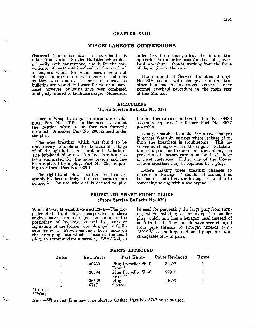
1801
CHAPTER XVIII
MISCELLANEOUS
General-The information in this Chapter istaken from various Service Bulletins which dealprimarily with conversions, and is for the con-venienc6 of personnel involved in the overhaulof engings which for some reason were notchanged in accordance with Service Bulletinsas thev were issued. In most instances thebulletiis are reproduced word for word; in somecases, however, bulletins have been combinedor slightly altered to facilitate usage. Numerical
CONVERSIONS
order has been disregarded, the informationappearing in the order used for describing-over-haul procedure -that is, working from the frontof the engine to the rear.
The material of Service Bulletins throughNo. 318, dealing with changes or informationother than that on conversions. is covered undernormal overhaul procedure in the main textof this Manual.
Current Wasp Jr. Engines incorporate a solidplug, Part No. 20159, in the nose section atihe-'location where a breather was formerlyinstalled. A gasket, Part No. 233, is used underthe plug.
The nose breather, which was found to beunnecessary, was eliminated because of leakageof oil through it in some airplane installations.The left-hand blower section breather has alsobeen eliminated for the same reason and hasbeen replaced by a plug, Part No. 255, requir-ing an oil seal, Part No. 33891.
The right-hand blower section breather as-sernbly has been redesigned to incorporate a hoseconnection for use where it is desired to pipe
BREATEERS(From Servlce Bulletln No. 818)
PROPELLER SEAFT FRONT PLUGS(From Servloe Bulletln No. 270)
the breather exhaust outboard. Part No. 38436assembly replaces the former Part No. 8927assembly.
It is permissible to make the above changesin earlier Wasp Jr. engines where leakage of oilfrom the breathers is troublesome. This in-volves no changes within the engine. Substitu-tion of a plug for the nose breather, alone, hasproved a satisfactory correction for this leakagein most instances. Either one of the blowersection breathers may be replaced by a plug.
Before making these breather changes toremedy oil leakage, it should, of coutse, firstbe made certain that the leakage is not due tosomething wrong within the engine.
Wasp H1-G, Eornet E-G and E8-G-The pro-pellei shaft front plugs incorporated in theseengines have been redesigned to eliminate thepossibility of breakage caused by excessivetightening of the former pipe plug 4nd to facili-tate removal. Provisions have been made onthe large plug, into which is inserted the smallplug, to accommodate a wrench, PWA-1733, to
be used for preventing the large plug from turn-ing when installing or removing the smallerplug, which now has a hexagon head instead ofan Allen head. The threads have been changedfrom pipe threads to straight threads (%"-18NF-3), so the large and small plugs are inter-changeable only in pairs.
PARTS AFFECTEI)
Part Narne Parts Replaced UnltsUnlts
1
1
11
*Hornet**Wasp
New Parts
36783
36784
366395747
Plug-Propeller ShaftFront*Plug-Propeller ShaftFront**PIugGasket
24307 1
299L9 1
11603 1
Note-When installing new type plugs, a Gasket, Part No. 5747 must be used.
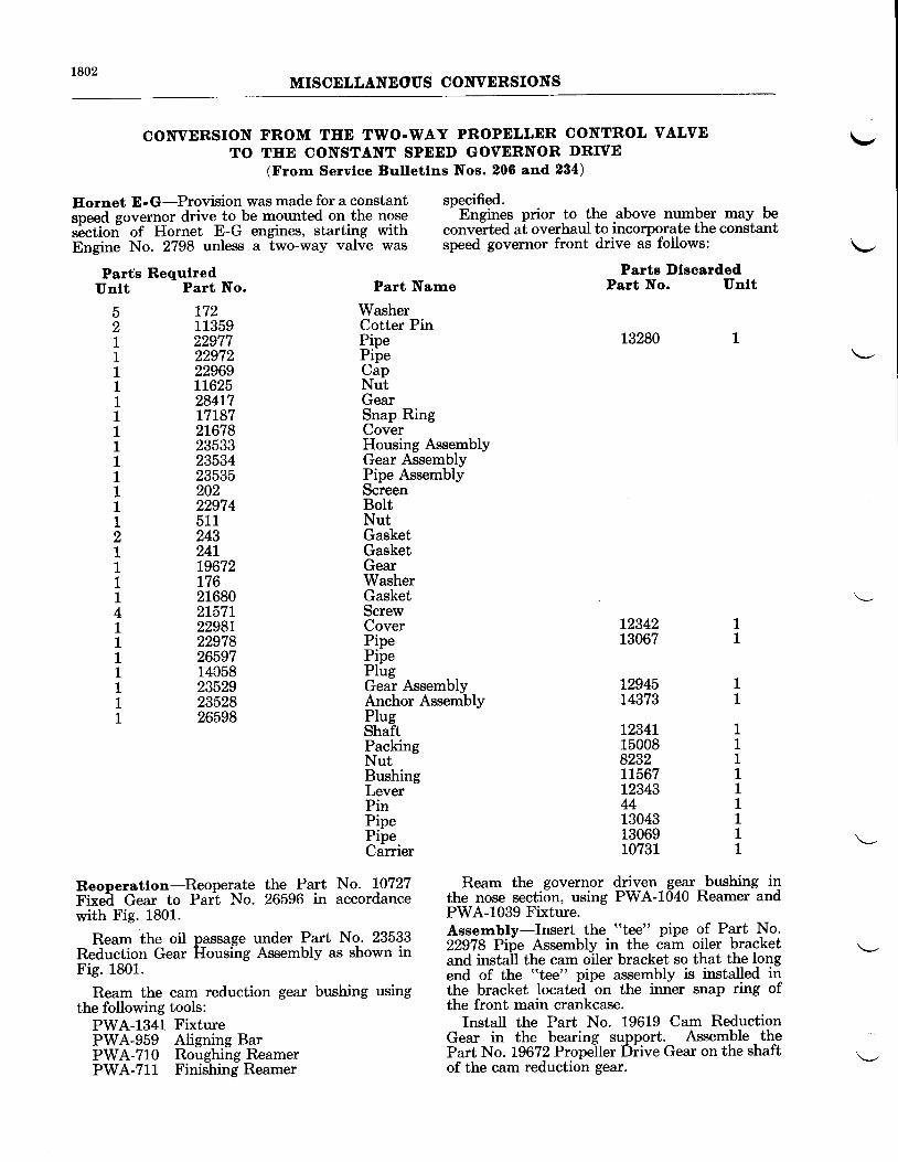
1802MISCELLANEOUS CONVERSIONS
CONVERSION FROM TEE TWO.WAY PROPELLER CONTROL VALVETO THE CONSTANT SPEDD GOVERNOR DRTVE
(Frorn Servlce Bulletlns Nos. 206 and 234)
Eornet E-G-Provision was made for a constant specified.**a e"*rnor drive to be mounted on the nose
- Engines prior to the above number may be
"6"iio"- of Hornet E-G engines, starting with convelted at overhaul to incorporate the constant-E;;il" No. 2798 unless a Two-*ay valie was speed governor front drive as follows:
Parf,s Requlred Parts l)lsoardedPart No. Unlt
\-,
Unlt
52I1111111111112111141I11111
Part No.
t7211359229772297222969L1625284L7L71872L6782353323534235352022297451124324L19672L76216802L57r2298r229782659714058235292352826598
Part Narne
WasherCotter PinPipePipecapNutGearSnap RingCoverHousing AssemblyGear AssemblyPipe AssemblyScreenBoltNutGasketGasketGearWasherGasketScrewCoverPipePipePlugGear AssemblyAnchor AssemblyPIugShaftPackingNutBushingLeverPinPipePipeCarrier
L3280
12342 113067 1
12945 1t4373 1
t234L150088232L1567L234344130431306910731
111111111
Reoperatlon-Reoperate the Part No. L0727 Ream the governor driven gear_bushing i4FE;a- 6gai to Prri No. 26596 in accordance the nose section, using PWA-1040 Reamer andwith Fig. 1801. PWA-1039 Fixture.
seTi6ePa":l ftT,:s,-& H:'-il,s'.J,t"3'f?l fnl,'-fiflr#::#il"l *:-#tr ;f';i,#;};;Fig' 1801' end of th" iii"";' pipe rss"-Etv Ir i"rtuu"a ifi
Ream the cam reduction gear bushing using the bracket located on the inner snap ring ofthe following tools: the front main crankcase.
pWA-1g41 Fixture Install the Part No. 19619 Cam ReductionFWA-$bg- Atig"i"g g.t Gear in the_ bearing_ support. Assemble thepwA-iig noighiifn"u*"t Part No. 19672 Propeller Diive Gear on the shaftpWA-711 Finfihing Reamer of the cam reduction gear.
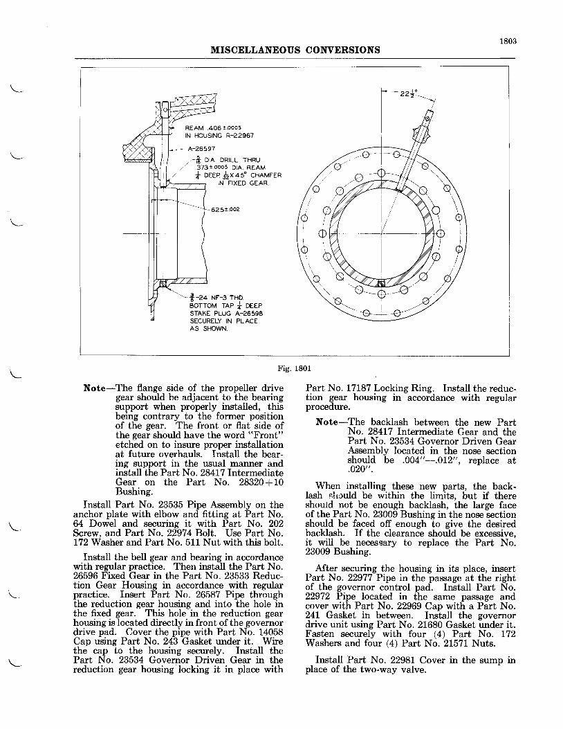
1803MISCELLANEOUS CONVERSIONS
REAM .406 !.ooo5IN HOUSING R22967
, . f i o rn . DRILL THRU./ 373i.ooo5 DtA. REAM
+ DEEP$xas ' CHAMFERIN FIXED GEAR
625!.002
$-z+ Nr-s rno.BOTTOM TAP i DEEPSTAKE PLUG A-26598SECURELY IN PLACEAS SHOWN.
,J ?h
\KI/
I
F ig. 1801
Note-The flange side of the propeller drivegear should be adjacent to the bearingsupport when properly installed, thisbeing contrary to the former positionof the gear. The front or flat side ofthe gear should have the word "Front"
etched on to insure proper installationat future overhauls. Install the bear-ing support in the usual manner andinstall the Part No. 28417 IntermediateGear on the Part No. 28320+10Bushing.
Install Part No. 23535 Pipe Assembly on theanchor plate with elbow and fitting at Part No.64 Dowel and securing it with Part No. 202Screw, and Part No. 22974 Bolt. Use Part No.172 Washer and Part No. 511 Nut with this bolt.
Install the bell gear and bearing in accordancewith regular practice. Then install the Part No.26596 Fixed Gear in the Part No. 23533 Reduc-tion Gear Housing in accordance with regularpractice. Insert Part No. 26587 Pipe throughthe reduction gear housing and into the hole inthe fixed gear. This hole in the reduction gearhousing is located directly in front of the governordrive pad. Cover the pipe with Part No. 14058Cap using Part No. 243 Gasket under it. Wirethe cap to the housing securely. InstaII thePart No. 23534 Governor Driven Gear in thereduction gear housing locking it in place with
Part No. L7L87 Locking Ring. Install the reduc-tion gear housing in accordance with regularprocedure.
Note-The backlash between the new PartNo. 28417 Intermediate Gear and thePart No. 23534 Governor Driven GearAssembly located in the nose sectionshould be .004"-.0t2", replace at.020".
When installing these new parts, the back-lash circuld be within the limits, but if thereshould not be enough backlash, the large faceof the Part No. 23009 Bushing in the nose sectionshould be faced off enough to give the desiredbacklash. If the clearance should be excessive,it will be necessary to replace the Part No.23009 Bushing.
After securing the housing in its place, insertPart No. 22977 Pipe in the passage at the rightof the governor control pad. Install Part No.22972 Pipe located in the same passage andcover with Part No. 22969 Cap with a Part No.241 Gasket in between. Install the governordrive unit using Part No. 21680 Gasket under it.Fasten securely with four (4) Part No. 172Washers and four (4) Part No. 21571 Nuts.
Install Part No. 2298L Cover in the sump inplace of the two-way valve.
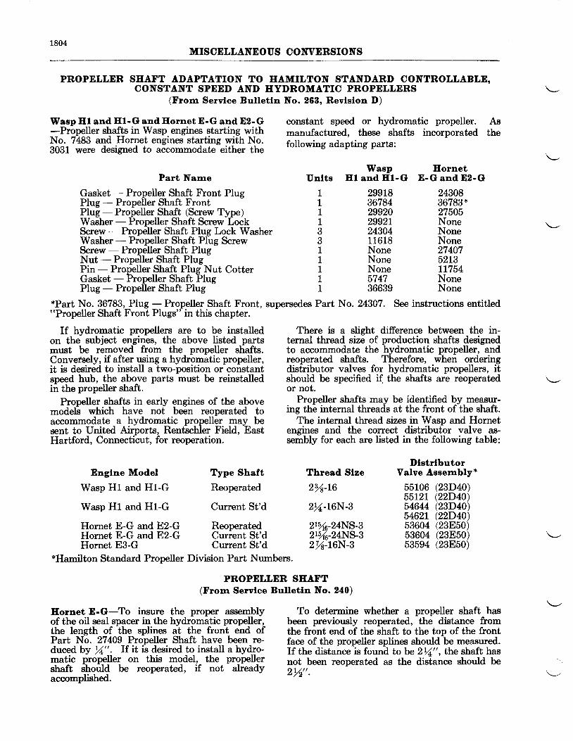
1804MISCDLLANDOIIS CONVERSIONS
PROPELLER SEAFT ADAPTATION TO HAMILTON STANDARD CONTROLLABLE,CONSTANT SPEED AND HYDROMATIC PROPDLLERS
(From Servlae Bulletln No. 268, Revlslon D)
Wasp El and El-G andEornetE-G and D2-G constant speed or hydromatic propeller.
;Prgg9^Ier sfalls in Wasp. engines starting. with manufactured, these shafts incorporatedNo. 7483 and Hornet engines starting
nl! T:: foUo*i"g adapting parts:3031 were designed to accommodate either the
Asthe
Wasp EornetUnlts Hl and El-G E-G and D2-GPart Narre
Gasket - Propeller Shaft Front PlugPIug - Propeller Shaft FrontPlug - Propeller Shaft (Screw Type)Washer - Propeller Shaft Screw LockScrew - Propeller Shaft Plug Lock WasherWasher - Propeller Shaft Plug ScrewScrew - Propeller Shaft PlugNut - Propeller Shaft PlugPin - Propeller Shaft Plug Nut CotterGasket - Propeller Shaft PlugPIug - Propeller Shaft PIug
1111331I111
299L836784299202992L2430411618NoneNoneNone574736639
2430836783*27505NoneNoneNone274075213LL754NoneNone
*Part No. 36783, PIug - Propeller Shaft Front, supersedes Part No. 24307. See instructions entitled"Propeller Shaft Front Plugs" in this chapter.
If hydromatic propellers are to be installed There is a slight difference between the in-on the subject engines, the above listed parts ternal thread size of production shafts designedmust be removed from the propeller shafts. to accommodate the hydromatic propeller, andConversely, if after using a hydromatic propeller, reoperated shafts. Therefore, when orderingit is desired to install a two-position or constant distributor valves for hydromatic propellers, itspeed hub, the above parts must be reinstalled should be specified if the shafts are reoperatedii the propeller shaft. or not.
Propeller shafts in early engines of the above Propeller shqftg may be identified !V--egsu-1-mo-dl6 *ttictt have nof bdn reoperated to ing the internal threads at the front of the shaft.accommodate a hydromatic propeller may be The internal thread sizes in Wasp and Hornetsent to United Airports, Rentschler Field, East engines and the correct distributor valve as-Hartford, Connecticut, for reoperation. sembly for each are listed in the following table:
DlstrlbutorThread Slze Valve Assembly*Englne Model
Wasp H1 and H1-G
Wasp H1 and Hl-G
Hornet E-G and E2-GHornet E-G and E2-GHornet E3-G
Type Shaft
Reoperated
Current St'd
ReoperatedCurrent St'dCurrent St'd
214-16
2y4-L6N-3
215/16-24Ns.32r%6_24N5_32y8-L6N-3
55106 (23D40)55r2t (22D40)54644 (23D40\5462I Q2D40\53604 (23E50)53604 (23E50)53594 (23850)
*Hamilton Standard Propeller Division Part Numbers.
PROPELLDR SEAFT(From Servlee Bulletln No. 240)
Eornet E-G-To insure the proper assemblyof the oil seal spacer in the hydromatic propeller,the length of the splines at the front end ofPart No. 27409 Propeller Shaft have been re-duced by rZ". If it is desired to install a hydro-matic propeller on this model, the propellershaft should be reoperated, if not alreadyaccomplished.
To determine whether a propeller shaft hasbeen previously reoperated, the distance fromthe front end of the shaft to the top of the frontface of the propeller spline,s should be measured.If the distance is found to be 2r/a,,, the shaft hasnot been reoperated as the distance should be2Yz!'.
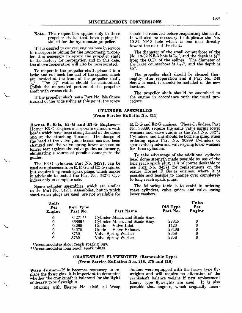
1805MISCDLLANDOIIS CONVERSIONS
Note-This reoperation applies only to thosepropeller shafts that have piping in-stalled for the hydromatic propeller.
If it is desired to convert engines now in serviceto incorporate piping for the hydromatic propel-Ier, it is necessary to return the propeller shaftto the factory for reoperation and in this case,the above reoperation will also be incorporated.
To reoperate the propeller shaft, place it in alathe and- cut back the end of the splines whichare located at the front of the propeller shaft,tl". The rl" radius should be maintained.Pbtistr the reoperated portion of the propellershaft with crocus cloth.
If the propeller shaft has a Part No. 240 Screwinstead of tlie wide spline at this point, the screw
UnltsPer New Type
Englne Part No.
should be removed before reoperating the shaft.It will also be neccssary to duplicate the No.10-32 NF-3 hole which is one inch directlytoward the rear of the shaft.
The diameter of the small counterbore of theNo. 10-32 NF-3 hole is Vn" , and the depth rs rZ,"from the O.D. of the splines. The diameter ofthe Iarge counterbore is rYn", and the depth is/n".
The propeller shaft should be cleaned thor-oughly after reoperation and if Part No. 240Screw is used, it should be installed in the newlocation.
The propeller shaft should be assembled tothe engine in accordance with the usual pro-cedure.
is to assist in orderingguides and valve spring
UnltsOld Type PerPart No. Dnglne
CYLINDER ASSEMBLIES(Frorr Servloe Bulletln No. 81f)
Eornet E, E-G, E2-G and E8-G Englnes- E,E-GandE2-Gengines. TheseCylinders,PartHornet E3-G Engines incorporate cylinders with No. 36889, require the same valve spring lowerheads which have been strengthened at the dome washers and valve guides as the Part No. 3427Land at the attaching threads. The design of Cylinders, and this should be borne in mind whenthe head at the valve guide bosses has also been ordering spare Part No. 36889 Cylinders orchanged and the valve spring lower washers no spare valve guides and valve spring lower washerslongel seat against the valve guides as formerly, for these cylinders.eliminating a so'rce of possible damage to the
To take advantage of the additional cylindergluoes' head dome strength-made possible by useof theThe E3-G cylinders, Part No. 34271, can be long reach,spark plug, it is of course desirable to
used as replacements on E, E-G and E2-G engines, use- _ Part No. 34271 for replacements on. thebut requiie long reach spark plugs, which makes earlier Hornet E Series engines, where it -oit advftable to-install the Part No. 34271 Cyl- possible and feasible to change over completelyinders only in complete sets. to long reach spark plugs.
Spare cylinder assemblies, which are similar The following tableto the Pait No. 3427I Assemblies, but in which spare cylinders, valveshort reach plugs are used, are not available for lower washers:
Part Narne
3427Ix* Cylinder Mach. and Studs Assy.36889* Cylinder Mach. and Studs Assy. 27845 I34269 Guide - Valve Inlet L420 I34270 Guide - Valve Exhaust 23408 I8?59 Valve Spring Washer 9358 I8759 Valve Spring Washer 9356 I
*Accommodates short reach spark plugs.**Accommodates long reach spark plugs.
CRANKSEAFT FLYWEIGETS (Removable Type)(From Servlae Bulletlns Nos. 218' 275 and 810)
Wasp Junlor-If it becomes necessary to re- Juniors were equipped with the heavy type fly-place-the flyweights, it is important to determine weights and will require no alteration of thei'hether the crankshaft is balanced for the ltght crankshaft balance weight if new replacementor heavy type flyweights. heavy type flyweights are used. It is also
Starting with Enghe No. L248, all Wasp possible that engines, which originally incor-
IIII9I
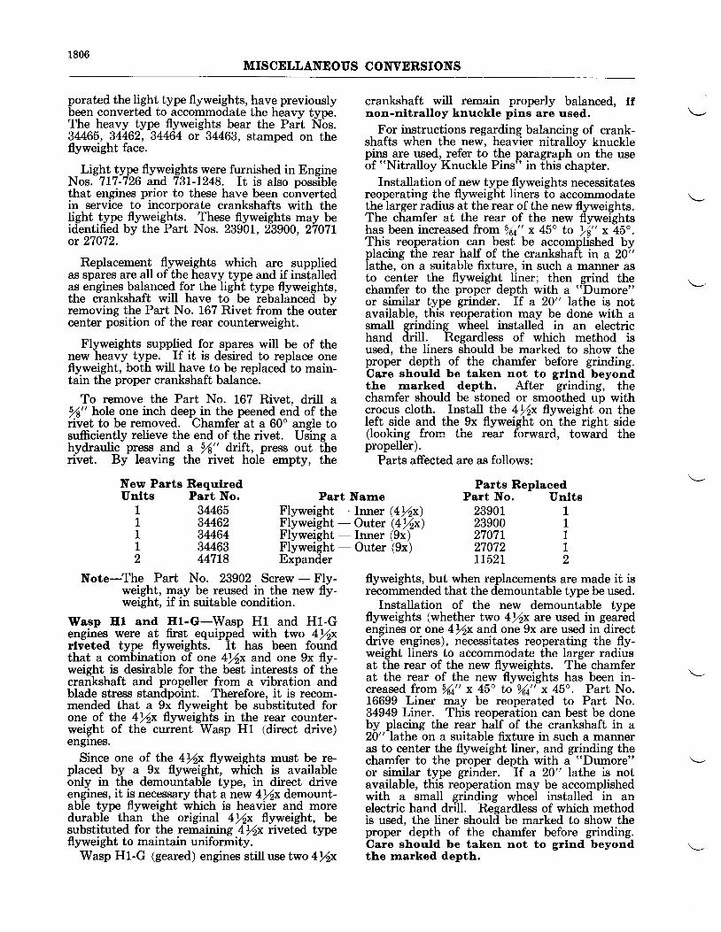
1806MISCDLLANDOUS CONVDRSIONS
porated the light type flyweights, have previouslybeen converted to accommodate the heavy type.The heavy type flyweights bear the Part Nbs.34465, 34462, 34464 or 34463, stamped on theflyweight face.
Light type flyweights were furnished in EngineNos. 717-726 and 73L-L248. It is also possiblethat engines prior to these have been convertedin service to incorporate crankshafts with thelight type flyweights. These flyweights may beidentified by the Part Nos. 2390L,23900, 2707Lor 27072.
Replacement flyweights which are suppliedas spares are all of the heavy type and if installedas engines balanced for the light type flyweights,the crankshaft will have to be rebalanced bvremoving the Part No. 167 Rivet from the outercenter position of the rear counterweight.
Flyweights supplied for spares will be of thenew heavy type. If it is desired to replace oneflyweight, both will have to be replaced to main-tain the proper crankshaft balance.
To remove the Part No. 167 Rivet, drill asf" hole one inch deep in the peened end of therivet to be removed. Chamfer at a 60o angle tosufficiently relieve the end of the rivet. Using ahydraulic press and a /8" drift, press out therivet. By leaving the rivet hole empty, the
New Parts Requlred
crankshaft will remain properly balanced, tfnon-nltralloy knuckle plns are used.
For instructions regarding balancing of crank-shafts when the new, heavier nitralloy knucklepins are used, refer to the paragraph on the useof "Nitralloy Knuckle Pins" in this chapter.
Installation of new type flyweights necessitatesreoperating the flyweight liners to accommodatethe larger radius at the rear ofthe new flyweights.The chamfer at the rear of the new flyweightshas been increased from 5/4,,x 4bo to rf,, x 48".This reoperation can best be accomplished byplacing the rear half of the crankshafl in a 20i'lathe, on a suitable fixture, in such a manner asto center the flyweight liner; then grind thechamfer to the proper depth with a "Dumore"
or similar type grinder. If a 20" lathe is notavailable, this reoperation may be done with asmall grinding wheel installed in an electrichand drill. Regardless of which method isused. the liners should be marked to show theproper depth of the chamfer before grinding.Care should be taken not to grlnd beyondthe marked depth. After grinding, thechamfer should be stoned or smoothed up withcrocus cloth. Install the 4/2x flyweight on theleft side and the 9x flyweight on the right side(looking frorn ihe rear forward, toward thepropeller).
Parts affected are as follows:
Parts ReplacedPart No. Unlts
34465344623446434463447L8
Note-The Part No. 23902 Screw - Flv-weight, may be reused in the new fly-weight, if in suitable condition.
Wasp Hl and Hl-G-Wasp Hl and Hl-Gengines were at first equipped with two 4fuxrlveted type flyweights. It has been foundthat a combination of one 4rlx and one 9x fly-weight is desirable for the best interests of thecrankshaft and propeller from a vibration andblade stress standpoint. Therefore, it is recom-mended that a 9x flyweight be substituted forone of the 4ftx flyweights in the rear counter-weight of the current Wasp HL (direct drive)engrnes.
Since one of the 4ftx flyweights must be re-placed by a 9x flyweight, which is availableonly in the demountable type, in direct driveengines, it is necessary that a new 4/2x demount-able type flyweight which is heavier and moredurable than the original 4/2x flyweight, besubstituted for the remaining 4/2x nveted typeflyweight to maintain uniformity.
Wasp Hl-G (geared) engines still use two 4/2x
2390r239002707L27072TT52T
11112
flyweights, but when replacements are made it isrecommended that the demountable type be used.
Installation of the new demountable typeflyweights (whether two 4rlx are used in gearedengines or one 4lx and one 9x are used in directdrive engines), necessitates reoperating the fly-weight liners to accommodate the larger radiusat the rear of the new flyweights. The chamferat the rear of the new flyweights has been in-creased frorn fta" x 45o to l(4" x 45". Part No.16699 Liner may be reoperated to Part No.34949 Liner. This reoperation can best be doneby placing the rear half of the crankshaft in a20" lathe on a suitable fixture in such a manneras to center the flyweight liner, and grinding thechamfer to the proper depth with a "Dumore"
or similar type grinder. If a 20" lathe is notavailable, this reoperation may be accomplishedwith a small grinding wheel installed in anelectric hand drill. Regardless of which methodis used, the liner should be marked to show theproper depth of the chamfer before grinding.Care should be taken not to grlnd beyondthe rnarked depth.
Unlts Part No. Part NameFlyweight'- Inner (AYzx)Flyweight - Outer @%x)Flyweight - Inner (9x)Flyweight - Outer (9x)Expander
11I12
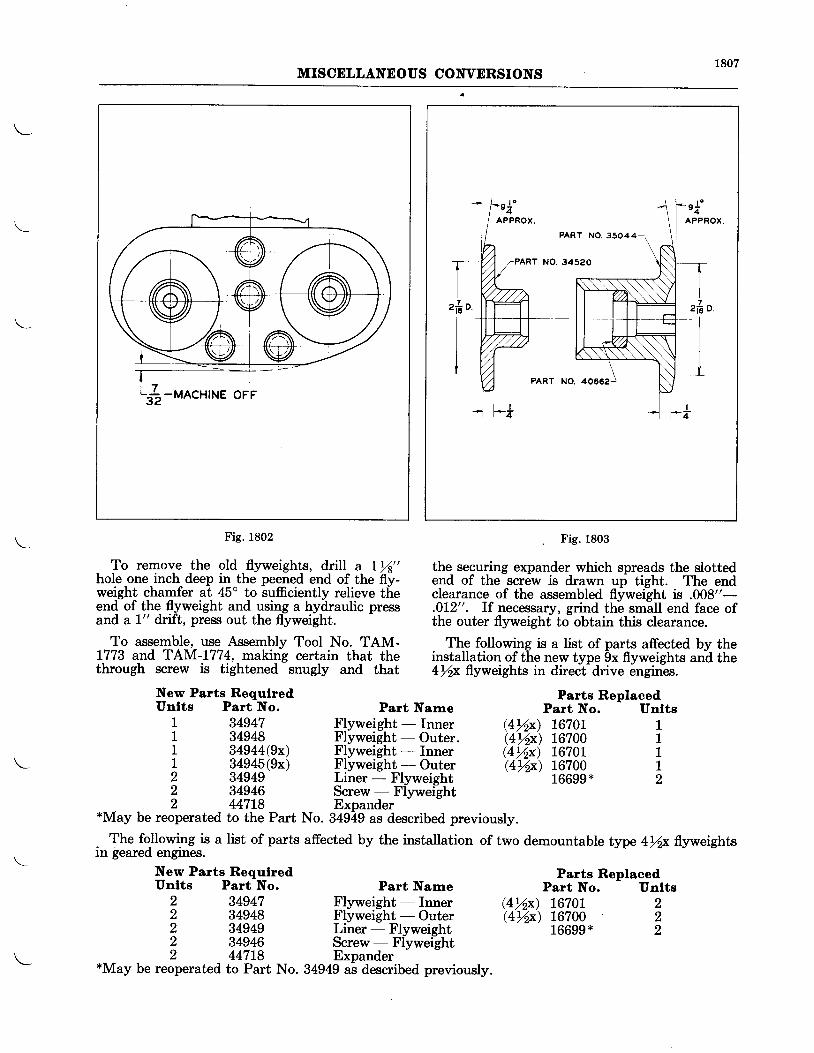
1807MISCELLANNOUS CONVERSIONS
e{
PART NO.35044
PART NO.34520
Fig. 1803
To remove the old.flyweights, dylll a- Lrl" the securing expander which spreads the slottedhole-one-inch deep i1^the peened end of the fly- end of the-scr6w is drawn uf tight. The endweigh! chamfer ?t- 45" to sufficiently reljeve the clearance of the assembled flyweight is .008"-end of the flyweight and using a hydraulic press .0I2". If necessarv, grind th6 sm6ll end face ofand a I" dift, press out the flyweight. the outer flyweight- to-obtain this clearance.
Fig. 1802
New Parts RequlredUnlts Part No.
New Parts RequlredUnlts Part No.
2 3494t
Part Narre
Part NarrreFlyweight - InnerFlyweight - OuterLiner - FlyweightScrew - FlyweightExpander
Parts ReplaoedPart No. Unlts
Parts ReplacedPart No. Unlts
222
GYd 16701Q%x) 16700
To assemble, use Assembly Tool No. TAM-1773 and TAM-L774, making certain that thethrough screw is tightened snugly and that
The following is a list of parts affected by theinstallation of t-he new type 9x flyweights an-d the4rlx flyweights in direct drive engines.
I q4q47 Flyweight - Inner $%x) L670I 11 q4948 Flyweight - Outer. (4%x) 16200 t1 q4Q+!(Qx) Flyweight - Inner @Yzx) 1G201 1L 34945(9x) Flyweight -- Outer $%x) 16?00 12 34949 Liner - Flyweight 16699* 22 34946 Screw - Flyweight2 44718 Expander*May be reoperated to the Part No. 34949 as described previously.
. The following is a list of parts affected by the installation of two demountable type 4rlx flyweightsin leared engines.
2 349482 349492 349462 447L8
*May be reoperated to Part No. 34949 as described previously.
16699*
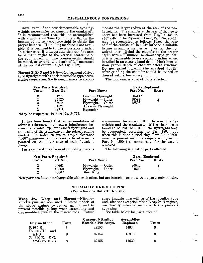
MISCELLANEOUS CONVERSIONS
Installation of the new demountable type fly- modate the larger radius at the rear of the newweights necessitates rebalancing the crankshaft. flyweights. The chamfer at the rear of the newerIt is recommended that this be accomplished liners has been increased from 22Yu" x 45o towith a milling machine by milling a flat on the 25A"x45". TheFlyweightliner,PartNo.20SlL,bottom of the rear counterweight to obtain the may be reoperated as follows: Place the rearproper balance. If a milling machine is not avail- half of the crankshaft in a 24" lathe on a suitableiUt6, it is permissible to use a portable grinder. fixture in such a manner as to center the fly-In either case, it is important that the flat area weight liner. Grind the chamfer to the properbe at right angles to the vertical centerline of depth with a "Dumore" or similar type grinder,the counterweight. The counterweight should or it is permissible to use a small grinding wheelbe milled, or ground, to a depth of Vn" measured installed in an electric hand drill. Mark liner toat the vertical centerline (see Fig. 1802).
S;*,'3;"??1"*rlHt#tiltj'*:t"il:f itlllf:EornetE,E-GandE2-G-Replacementofrivet After grinding trhe chamfer should be stoned ortvp" nv*"ights with the demouitable type neces- dressed with a fine emery cloth.sitates reoperating the flyweight liners to accom- The following is a list of parts affected:
34777345203504434521447L8
*May be reoperated to Part No. 34777.
It has been found that an accumulation ofadverse tolerances may cause interference be-tween removable type crankshaft flyweights andthe inside of the crankcase on the subject enginemodels. In order to insure ample clearance(.060" minimum) at this point, a bevel is incor-porated on the outer edge of each flyweightflange.
Parts on hand may be used providing there is
New Parts RequlredUnlts Part No.
2 406612 406602 40662
a minimum clearance of .060" between the flv-weights and the crankcase. If the clearance
-is
found to be less than .060", the flyweights maybe reoperated, according to Fig. 1803, butwhen this is done a steel ring, Part No. 40662,must be pressed into the reoperated flyweightPart No. 35044 to compensate for the weightremoved.
The following is a Iist of parts affected.
Parts ReplacedPart No. Unlts
35044 234520 2
New Parts RequlredUnlts Part No. Part Name
Liner - FlyweightFlyweight - InnerFlyweight - OuterScrew - FlyweightExpander
Current Nltralloy AssernbllesKnuckle Pln Assys. Replaced
Parts ReplacedPart No. Unlts
205LL* 218597 218598 2
Unlts
22222
Part Name
Flyweight - OuterFlyweight - InnerSteel Ring
New parts are fully interchangeable with each other, but are interchangeable with old parts only in pairs.
NITRALLOY KNUCKLE PINS(From Servlce Bulletln No. 268)
Wasp Jr., Wasp and Eornet-Nitralloy spare kluckle pins will !e of_the nitralloy typeknuclkle pins are now used in latest model"q of and,withtheexceptionoftheW"qpJr.Bengines,the above engines to reduce galling and to are directly interchangeable with the previousprevent possible pickup when assembling and type pins.llisassembling pins in the master rods. Future See table below for parts affected.
Englne Model Unlts
R-985-B 8R-1340-H1 and
Hl-G 8R-1690-E, E-G,
E2-GandE3-G 8
32L53 4483 8
32L54
32t55
15318 8
11539 8
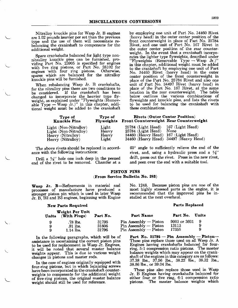
1809MISCELLANEOUS CONVERSIONS
Nitralloy knuckle pins for Wasp Jr. B enginesarcL.02 pounds heavier per set than the previoustvpe anil the use of them will necessitate re-baiancing the crankshaft to compensate for theadditional weight'
Spare crankshafts balanced for light type non-nitrilloy knuckle pins can be furnished, pro-vidine Part No. 23905 is specified for engineswith hve ring pistons, or Part No. 28102 forencines
'with fbur ring pistons. Otherwise,spires which are balanced for the nitralloyknuckle pins will be furnished'
When rebalancing Wasp Jr. B crankshafts,for the nitralloy pins there are two conditions tobe considered. If the crankshaft has beenchanged to incorporate the heavier type fly-weie[t, as explained under "Flyweights (Remov-abld T.vpe - Wasp Jr.)" in this chapter, addi-tional fu-eigfrt must be added to the crankshaft
by employing one unit of Part No. 34460 Rivet(heavy head) in the outer center position of thefront counterweight in place of Part No. 25784Rivet. and one unit of Part No. 167 Rivet inthe outer center position of the rear counter-weight. In the event that a crankshaft incorpo-rates the Iighter type flyweights, described under"Flyweights (Removable 'Iype - Wasp Jr.)"in this chapter, additional weight must be addedto the crankshaft by employing one unit of PartNo. 34460 Rivet (heavy head) in the outercenter position of the front counterweight innlace of the Part No. 25784 Rivet and also oneirnit of Part No. 34497 Rivet (heavy head) inplace of the Part No. 167 Rivet, at the sameiocation in the rear counterweight. The tablebelow outlines the various combinations offlyweights and knuckle pins, and lists the rivetsto be used for balancing the crankshaft withthese combinations.
Type olKnuakle Plns
Type of Rlvets (Outer Center Posltlon)Flywelghts FrontCounterwelght RearCounterwelght
Lieht (Non-Nitralloy) LightLiiht (Non-Nitralloy) HeavyHeavy (Nitralloy) HeavyHeavy (Nitralloy) Light
The above rivets should be replaced in accord-ance with the following instructions:
Drill a sf" hole one inch dqep iq the-peenedend of the iivet to be removed. Chamfer at a
25784 (Light Head) 167 (Light Head)25784 (Light Head) None34460 (Heavy Head) 167 (Light Head)34460 (Heavy Head) 34497 (Heavy Head)
60o angle to sufficiently relieve the end of therivet, and, using a hydraulic press and a 54"
drift, press out the rivet. Press in the new rivet,and peen over the end with a suitable tool.
Wasp Jr. B-Refinements in material andnroc&ses of manufacture have produced aStronger piston pin which is used in Iater WaspJr. BlB2-and 83 engines, beginning with Engine
New Parts Requlred
Welght Per UnltUnlts (Wfth Plugs) Part No.
9 .78 lbs. 317959 .91 lbs. 318069 1.14 lbs. 31796
PISTON PINS(From Servlce Bulletln No. 288)
Part Name
No. 1248. Because piston pins are one of themost highly stressed parts in the engine, it isrecommended that the improved pins be in-stalled at the next overhaul.
Pin Assembly - PistonPin Assembly - PistonPin Assembly - Piston
Parts Replaced
Part No. Unlts
9003 or 3601 I13113 I17355 9
In the following paragraphs, which will be ofassistance in ascertaining the comect piston pinsto be used for replacement in Wasp Jr. Engines,it will be noted that several master balanceweights appear. This is due to various weightchanges in pistons and master rods.
In the case of engines originally equipped withfour-ring pistons, but in which bqla-nclng screwshave been incorporated in the crankshaft counter-weishts to compensate for the additional weightof frve-ring pistons, the original master balanceweight should still be used for reference.
Part No. 81705 - Pln Assembly - Plston-These pins replace those used on all Wasp Jr. AEngines having crankshafts balanced for four-ring, 5:1 compression ratio pistons. The masterbalance weights which may appear on the crank-shaft of the engines in this category are as follows:37.38 lbs., 37.56 lbs., 38.22 lbs., 38.32 lbs.,38.86 lbs., or 39.04 lbs.
These pins also replace those used in {a,spJr. B En!"ines havinf crankshafts balanced foleither forir or five r-ing, 6:1 compression ratiopistons. The master balance weights which
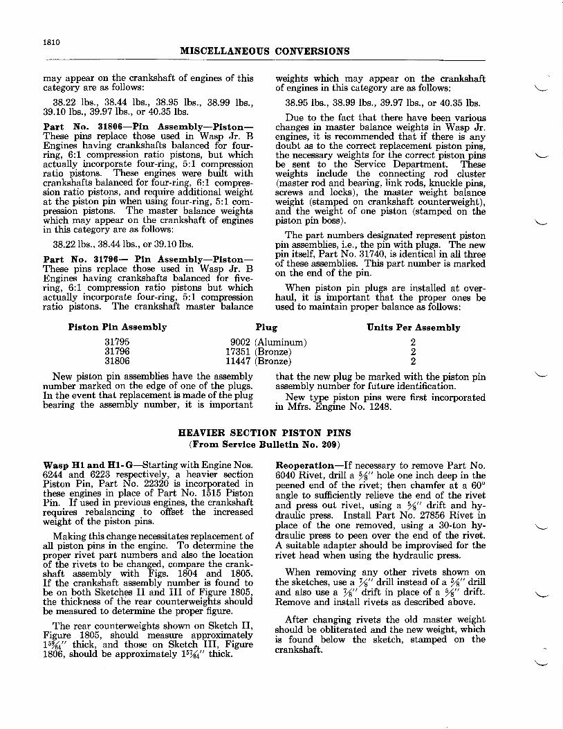
1810MISCELLANEOUS CONVERSIONS
may appear on the crankshaft of engines of thiscategory are as follows:
38.22 lbs., 38.44 lbs., 38.95 lbs., 38.99 lbs.,39.10 lbs.. 39.97 lbs., or 40.35 lbs.
Part No. 81806-Ptn Assernbly-Plston-These pins replace those used in Wasp Jr. BEngines having crankshafts balanced for four-ring, 6:1 compression ratio pistons, but whichactually incorporate four-ring, 5:1 compressionratio pistons. These engines were built withcrankshafts balanced for four-ring, 6:1 compres-sion ratio pistons, and require additional weightat the piston pin when using four-ring, 5:1 com-pression pistons. The master balance weightswhich may appear on the crankshaft of enginesin this category are as follows:
38.22 lbs., 38.44 lbs., or 39.10lbs.
Part No. 31796- Pln Assernbly-Plston-These pins replace those used in Wasp Jr. BEngines having crankshafts balanced for five-ring, 6:1 compression ratio pistons but whichactually incorporate four-ring, 5:1 compressionratio pistons. The crankshaft master balance
Plston Pln Assembly
317953179631806
Plug
weights which may appear on the crankshaftof engines in this category are as follows:
38.95 lbs., 38.99 lbs., 39.97 lbs., or 40.35 lbs.
Due to the fact that there have been variouschanges in master balance weights in Wasp Jr.engines, it is recommended that if there is anydoubt as to the correct replacement piston pins,the necessary weights for the correct piston pinsbe sent to the Service Department. Theseweights include the connecting rod cluster(master rod and bearing, link rods, knuckle pins,screws and locks), the master weight balanceweight (stamped on crankshaft counterweight),and the weight of one piston (stamped on thepiston pin boss).
The part numbers designated represent pistonpin assemblies, i.e., the pin with plugs. The newpin itself, Part No. 3L740, is identical in all threeof these assemblies. This part number is markedon the end of the pin.
When piston pin plugs are installed at over-haul, it is important that the proper ones beused to maintain proper balance as follows:
Unlts Per Assembly
222
9002 (Aluminum)7735t (Bronze)LL447 (Bronze)
New piston pin assemblies have the assemblynumber marked on the edge of one of the plugs.In the event that replacement is made of the plugbearing the assembly number, it is important
that the new plug be rnarked with the piston pinassembly number for ftrture identification.
New type piston pins were first incorporatedin Mfrs. Engine No. 1248.
IIEAVIER SECTION PISTON PINS(From Servlce Bulletln No. 200)
Wasp Hl and El-G-Starting with Engine Nos.6244 and 6223 respectively, a heavier sectionPiston Pin, Part No. 22320 is incorporated inthese engines in place of Part No. 1515 PistonPin. If used in previous engines, the crankshaftrequires rebalancing to offset the increasedweight of the piston pins.
Making this change necessitates replacement ofall piston pins in the engine. To determine theproper rivet part numbers and also the locationof the rivets to be changed, compare the crank-shaft assembly with Figs. 1804 and 1805.If the crankshaft assembly number is found tobe on both Sketches II and III of Figure 1805,the thickness of the rear counterweights shouldbe measured to determine the proper figure.
The rear counterweights shown on Sketch II,Figure 1805, should measure approximatelyl5%4tt thick, and those on Sketch III, Figure1806, should be approximately L5%4tt thick.
Reoperatlon-If necessary to remove Part No.6040 Rivet, drill a sf" hote one inch deep in thepeened end of the rivet; then chamfer at a 60oangle to sufficiently relieve the end of the rivetand press out rivet, using a /s" drift and hy-draulic press. Install Part No. 27856 Rivet inplace of the one removed, using a 30-ton hy-draulic press to peen over the end of the rivet.A suitable adapter should be improvised for therivet head when using the hydraulic press.
When removing any other rivets shown onthe sketches, use a 78" drill instead of a fu" drilland also use a l(" drift in place of a 51" dnft.Remove and install rivets as described above.
After changing rivets the old master weightshould be obliterated and the new weight, whichis found below the sketch, stamped on thecrankshaft.
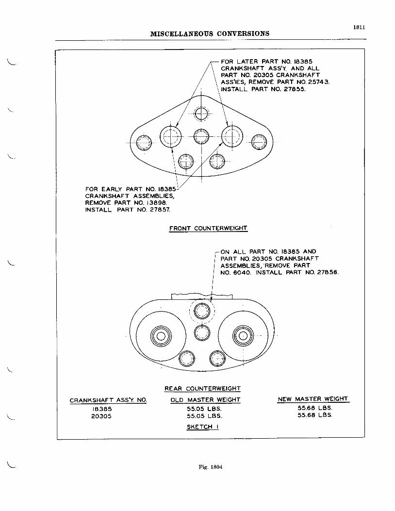
181 1MISCELLANEOUS CONVERSIONS
FOR LATER PART NO. 18385CRANKSHAFT ASS'Y. AND ALLPART NO. 2O3O5 CRANKSHAFTASS,IES, REMOVE PART NO.25743.INSTALL PART NO. 27655.
FOR EARLY PART NO. 18385CRANKSHAFT ASSEMBLIES,REMOVE PART NO. I3898.INSTALL PART NO. 27457.
CRANKSHAFT ASS,Y NO.r 8 3 8 520305
FRONT COUNTERWEIGHT
REAF COUNTERWEIGHT
OLD MASTER WEIGHT
55.05 LBS.55 .05 LBS.
SKETCH I
ON ALL PART NO, 18385 ANDPART NO. 2O3O5 CRANKSHAFTASSEMBLIES, 'REMOVE PARTNO. 6040. INSTALL PART NO.27A56,
NEW MASTER WEIGHT
55.68 LBS.5s.68 LBS.
Fig. 1804
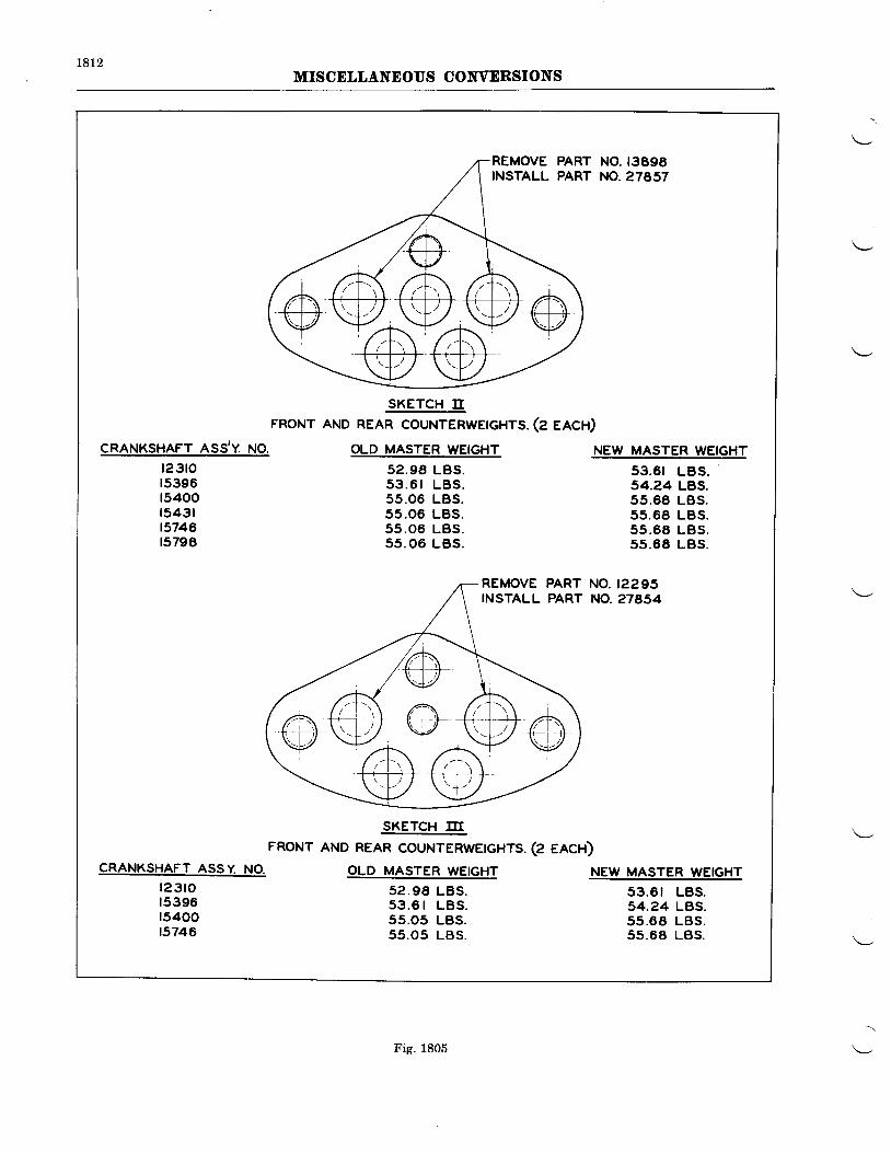
r8t2MISCELLANEOUS COIVVERSIONS
NO. t3898NO.27657
SKETCH IIFRONT AND REAR COUNTERWETGHTS. (Z EACH)
CRANKSHAFT ASS,Y. NO.
t23tot5396t5400t5431t5746t5798
OLD MASTER WEIGHT
52 .98 LBS.5 3 . 6 r L B S .55.06 LBS.55 .06 LBS.55 .06 LBS.5s .06 LBS.
NEW MASTELWEIGHT
53.61 LBS.s4.24 LBS.55.68 LBS.55 .68 LBS.55 .68 LBS.55.6E LBS.
NO. r2295NO.27854
SKETCH III
FRONT AND REAR COUNTERWETGHTS. (Z eeCn)CRANKSHAFT ASSY NO.
l 2 3 t o15396t5400t5746
OLD MASTER WEIGHT
52 .98 LBS.53 .6 | LBS .55.05 LBS.55.05 LBS.
NEW MASTER WEIGHT
53 .6 t LBS.54.24 LBS.55 .O8 LBS.55.68 LBS.
Fig. 1805
1813MISCELLANEOUS COIIVERSIONS
ROCKER AND ROCKER BEARINGS(From Servlce Bulletlns Nos. 235 anil262)
Wasp Jr. B Englnes-Curr_ent W".p Jr. B threads. These parts are interchangeable onlyEngines incorporate imp-roved rocker arm-as- as complete assemblies. The following is a listsemblies. The rocker is larger to accommodate of the parts affected if it is desired to make thisa greater capacity double row bearing as,well as ;;"-;;a stronger valve adjusting screw with finer uua'E's'
New Parts RequlredUnlts Part No.
I 10678
I L0677
18 901618 95L4
18 9294
Part Name
Intake Rocker and BallCup AssemblyExhaust Rocker and BallCup AssemblyRocker BearingValve Clearance AdjustingScrew AssemblyValve Clearance AdjustingScrew Lock Nut
Parts ReplacedPart No. Unlts
3734 9
3735 I
314-D 363725 18
551 18
Chapters II and V of this manual should be on the bottom of the rocker boxes and alsoreferred to for instructions on disassembly and burring the sides of the rocker boxes with aassembly of the rocker arms. power driven, flexible drive rotary file.
Wheninstal l ingthelargetyperockers,acheck r r--- : --_ ar_ __--____, ^ , r , rst ouid be made" to aefbi#iire that ;"tr;l;;; To determine the amount of metal to be re'
;i;;;;";;iirtr L"i*"e" the rocter and ilit"ti- moved, a heavy tvpe rocker assemblv.should bei"a"r-"""t "r U"". If the clearance is insufficieirt, used as a guide as some cylinders will requireit should be obtained by burring off the ridge less burring than others.
INSTRUCTIONS FOR INSTALLING PRATT AND WEITNEY LUBRICATORON WASP JR. B ENGINES
(Frorn Servlce Bulletln No. 320, Revlslon A)
The following instructions cover the changes & Whitney automatic lJ'bricator.required to con"vert Wasp Jr. B Engines having The parts listed.below .are required for con-either the grease type or one-shot rocker box verting a grease-lubricated engrne to one wrthlubrication system to permit the use of tt e Pratt automatic lubrication.
Part No. Part Narre
8955 Gasket - Rocker ShaftLl52l Plug - Cylinder Head14779 Gasket - Rocker Cover14814 Spring - Rocker Cover20L42 Shaft - Rocker20388 Ball End26843 Pipe Assembly - Inter Ear26841 Pipe Assembly - Connection to Main Feed2ol4l Hose37564 Clamp20255 Fitting - Inter Cylinder26090 Clamp33393 Brace27507 Clip27503 Bushing13705 Screw7L748 Nut287LL Pipe Assembly - R,ear Case to Lubricator33395 Pipe Assembly - Lubricator to Cylinder (Lower)
Quanttty
1818181818L2T 71
2040182L1I1111
t8t4MISCELLANEOUS CONVERSIONS
Part No. Part Narne
28709 Pipe - Lubricator to Cylinder (Upper)32330 Lubricator22747 Bushing - Reducing22348 ElbowLL42 Gasket - Lubricator12009 Nut32966+4 Stud12L84 Grommet30489 Seal Rocker Shaft31724 Seal - Rocker Shaft
Quantity111o2241
1818
Assernbly-Install two Part No. 20142 RockerShafts in each cylinder in place of the formerPart No. 8952 Rocker Shaft, and secure withPart No. 12606 Nut. Note: A new Part No.8955 Gasket should be used beneath each PartNo. 12606 Nut. Part No. 30489 Oil Seal shouldbe used between these gaskets and the cylinders,and Part No. 31724 Oil Seal should be installedbetween the washer and the cylinder on the smallend of the rocker shaft. Install two Part No.11521 Plugs in each cylinder where the greasefittings were removed.
Install Part No. L4814 Rocker Cover Springsin place of ones removed.
Assemble 18 units of inter-cylinder fittings,Part No. 20255, which connect the rocker shaftsof adiacent cylinder; also assemble the 17 PartNo. 2OS+g Inter-Ear Pipe Assemblies to therocker shafts of all cylindeis except No. 1 Intake.On No. 1 Intake Rocker Shaft assemble thePart No. 26841 Pipe Assembly - Connectionto Main Feed. Tighten pipes securely, makingsure that the tee connection of the Part No. 26841Pipe Assembly faces the rear of the engine.
Note-Where hose connections connect thetwo pipes together, it is first necessaryto slip the hose on one of the two mat-ing pipes. After the pipes have beentighiened and properly aligned-, slidettie hose over the gap between the twopipe assemblies. Part No. 37564 ClgrynsfrbUa be used to bind both ends of thehose connections securely.
Install four Part No. 32966 * 4 Studs in thefuel pump pad in place of those pr-evioully re-moved. When properly installed, the height ofthe stud from th-e fulel pump pad should be 23f".Install the Part No. g23g0 tubricator and FueIPump Drive Assembly on the fuel pugp driygpad in the rear section, using a Part No. 1142Gasket between the lubricalor and the pad.Install the fuel pump in accordance with- regularpractice, usine i Pait No. 1142 Gasket betweenihe fuei pum-p and drive. Install a Part No.22348 Elbow in the oil inlet and another in theoil outlet of the lubricator.
Note-The oil outlet is located at the bottomof the lubricator and the oil inlet is inthe center of the lubricator housing.
Dlsassernbly-Remove the following parts inaccordance with regular practice:
Rocker box covers, gaskets, and rocker boxcover spnngs.Push rod assemblies from No. 1 intake,No. l exhaust, No. 2 intake, No. 2 exhaust,No. 3 intake, No. 3 exhaust, No. 4 exhaust,No. 7 exhaust, No. 8 intake, No. 8 exhaust,No.9 intake, and No. 9 exhaust.Grease fittings from all cylinders.Rocker shafts from all cylinders.Remove Part No. 134 Plug from the leftside of the rear section just below the gunsynchronizer pad.Remove the fuel pump and also the fuelpump drive assembly.Remove the present fuel pump attachingstuds and also the rear section to blowerattaching nut located below the fuel pumppad.
8. Remove primer line clamps from No. 1Intake Pipe.
Reoperatlon-The twelve Part No. 10905 PushRod Assemblies should be reoperated to PartNo. 20508 Push Rod Assemblies as follows:Remove the Part No. 10667 Ball End from theend of the push rod which seats in the ball endsocket in the tappet (crankcase end of rod),and replace with Part No. 20388 Ball End inaccordance with regular practice.
Note-If the push rod is not Iong enough afterassembling new baII ends, a Part No.10942 Spacer may be inserted betweenthe push rod and ball end to obtainthe proper length. The rounded edgeof the spacer should be toward theball end. and in no case should morethan one spacer be used under a ballend.
Due to possible interference of the rear sectionattaching stud when assembling the lubricator,it is best to check the projected length of thestud which should be 94" as measured from theblower face. If the length exceeds this, the end ofthe stud should be filed down to obtain thislength. A Part No. 12009 Nut should then beinstalled on the stud in place of the nut previouslyremoved.
1 .
2 .
t ) .
4.5.
b .
a,t .
1815
MISCELLANEOUS CONVERSIONS
Install Part No. 22747 Reducing Bushing inthe rear section hole from which the Part No. 134Plug was previously removed. Install PartNo. 22348 Elbow in this reducer. ConnectPart No. 287t1Pipe Assembly from the oil inletside of the lubricator to the Part No. 22348Elbow in the rear section.
Connect one end of Part No. 33395 Pipe As-sembly from the oil outlet side of the lubricatorand one end of Part No. 28709 Pipe to the teeconnection of Part No. 26841 Pipe Assembly.The Part No. 33395 and Part No. 28709 Pipesshould be connected together by means of PartNo. 20141 Hose.
The Part No. 33395 Pipe Assembly should besecured to the rear section with Part No. 27503Bushing, Part No. 27507 Clip, and Part No.33393 Brace. Fasten the brace to the most con-venient blower to rear section stud, using PartNo. 12009 Nut in place of the present rear sec-tion attaching nut. Part Nos. 13705 Screw and1L748 Nut should be used to fasten the brace andclip together. Part No. 26090 Clamp should beused to fasten the Part No. 28709 Pipe and theprimer line of No. 1 Cylinder to the intake pipe.Part No. 8650 Screw and Part No. 8651 Nutfrom the old clamp should be used to fasten thisclamp securely.
Install push rods, check valve clearances andinstall rocker box covers with new gaskets.
Note-Before starting the engine, the rockerbox lubrication sYstem should beprimed with engine oil.
Adiustrnent of the Pratt & Whltney Lubri'cat"or-Located on the Iubricator is a scale for theadiustment of oil flow to the rocker mechanism.When first installing this device on an engine,it is best to set the arrow at a point somewherebetween one (1) and one and three quarters(1?r) on the scale. However, this may not be anerilanent setting, but may be used during thehrst eneine test'after installation of the unit.As a pr6caution it is well to remove the rockerbox cbvers after about 10 minutes of runningto see if sufficient oil is being furnished to therocker mechanism of each cylinder. If an oversupply is being furnished, it is likely to causesti'efit smoLine?om the exhaust, which may becolrected by Jetting the pointer at a lower posi-tion on th6 scale.* If there is not enough oilfound in the rocker boxes, that is, if the springs,washers and rockers are not wet with oil, adjust-ment should be toward the higher end of thescale.
Engines already having a one-shot lubricationsvsteir mav be
-converied to incorporate the
altomatic lubrication system as follows:
Part No.New Parts Requlred
Part Narne32330 Lubricator33395 Pipe Assy. - Lubricator to Cylinder (Iower)28709 Pipe - Lubricator to Cylinder (upper)20L4I Hose33393 Brace27507 CIip13705 Screw27503 Bushing11748 Nut12009 Nut32966+4 Stud22348 Elbow22717 luslring ReducingL142 Gasket - Lubricator
\- ?331" .Fli: *::nBlI -_ LtTl"l?""" to Main Feed287LL Pipe Assembly - Rear Case to Lubricator26090 Clamp
*Used on engines not hiving the Part No. 26843 Inter Ear Pipe Assemblies.
Dlsassembly-Remove the fuel pump and fuelpump drive assembly as previously described.Aho remove the fuel bump-hold down studs andthe blower to rear tiold down nut located be-neath the fuel pump.
Remove the two pipes leading from the one-shot valve to No. f ind No. O Cylinders, alsoremove the valve from the left side of the rearsection.
AssernblyNote-Some engines may have earlier type
inter-ear "pipe
assemblies than thosenow furnish-ed' In this case both thetee connection pipe of No. 1 Cylinderand its matins pipe assembly will haveto be replace-d-bY a Patt No. 26841Pipe Ass-embly --Connectio^n to MainFe^ed and a Part No. 26843 PiPe As-sembly. On No. 6 Cylinder the inter-
Quantlty11I211I1124312L112
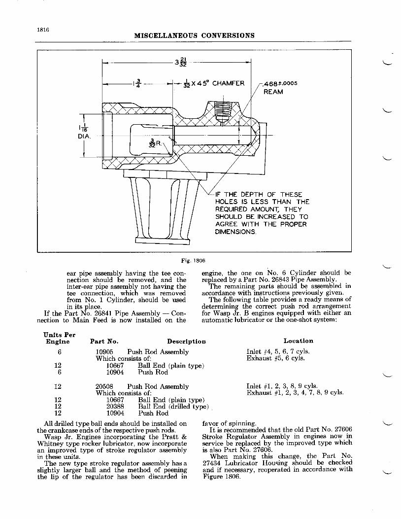
1816MISCELLANEOUS CONVERSIONS
Fig. 1806
ear pipe assembly having the tee con- engine, the one on No. 6 Cylinder should benection should be removed, and the replaced by a Part No. 26843 Pipe Assembly. ,inter-ear pipe assembly not having the The remaining parts should be assembled intee connection, which was removed accordance with instructions previously given.from No. 1 Cylinder, should be used The following table provides a ready means ofin its place. determining the correct push rod arrangement
If the Part No. 26841Pipe Assembly - Con- for Wasp Jr. B engines equipped with either annection to Main Feed is now installed on the automatic lubricator or the one-shot system:
Unlts PerEnglne Part No. Descrlptlon
6 10905 Push Rod AssemblyWhich consists of:
12 10667 Ball End (plain type)6 10904 Push Rod
L2 20508 Push Rod AssemblvWhich consists of:
12 10667 Ball End (plain type)12 20388 Ball End (drilled type)12 10904 Push Rod
Locatlon
Ir:JLet rt4,5, 6, 7 cyls.Exhaust 15, 6 cyls.
I n l e t # 1 , 2 , 3 , 8 , 9 c y l s .Exhaust #1, 2, 3, 4, '1 , 8,9 cyls.
All drilled type ball ends should be installed on favor of spinning.the crankcase-eirds of the respective push rods. It is recbmmended that the old Part No. 27606
Wasp Jr. Engines incorporating-the Pratt & Stroke Regulator Assembly in eng-ines now.inWhitn6y type rocker lubriiator, now incorporate service be ieplaced by the improved type whichan improved type of stroke regulator assembly is also Part No. 27606.in theie units.
- - When making this change, the Part No,
The new type stroke regulator assembly has a 27434 Lubricator Housing should be checkedslightly largdr baII and t[e method of feening and if necessary, reoperated in accordance withthe lip of the regulator has been discarded in Figure 1806.
$x+s" cHAMFER :469!.ooo5REAM
IF THE DEPTH OF THESEHOLES IS LESS THAN THEREQUIRED AMOUNI, THEYSHOULD BE INCREASED TOAGREE WITH THE PROPERDIMENSIONS.
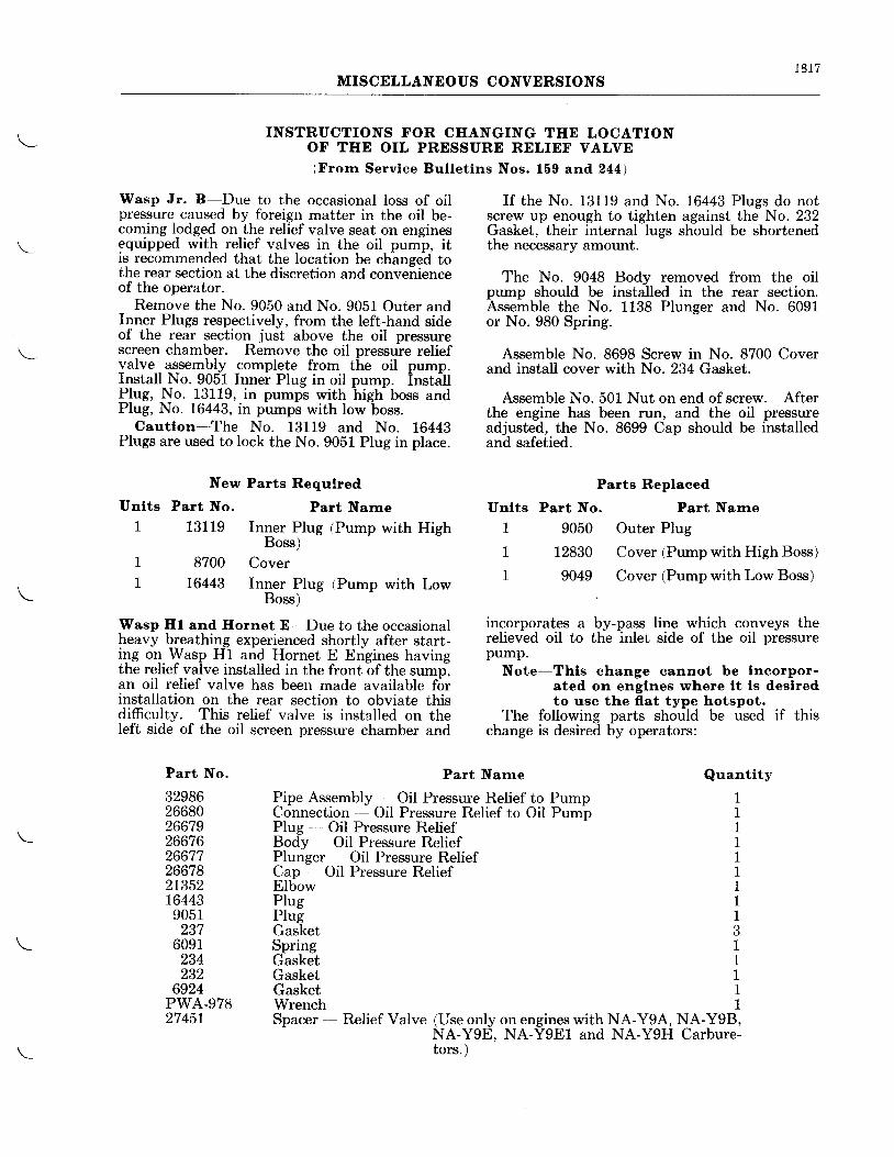
1 8 1 7MISCELLANEOUS CONVERSIONS
INSTRUCTIONS FOR CHANGING THE LOCATIONOF THE OIL PRESSURE RELIEF VALVE(Frorn Servlce Bulletlns Nos. 159 and244)
Wasp Jr. B-Due to the occasional loss of oilpressure caused by foreign matter in the oil be-coming lodged on the relief valve seat on enginesequipped with relief valves in the oil pump, itis recommended that the location be changed tothe rear section at the discretion and convenienceof the operator.
Remove the No. 9050 and No. 9051 Outer andInner Plugs respectively, from the left-hand sideof the rear section just above the oil pressurescreen chamber. Remove the oil pressure reliefvalve assembly complete from the oil pump.Install No. 9051 Inner Plug in oil pump. InstallPlrg, No. 13119, in pumps with high- boss andPlug, No. 16443, in pumps with low boss.
Cautlon-The No. 13119 and No. 16443Plugs are used to lock the No. 9051 Plug in place.
New Parts Requlred
Unlts Part No. Part Narne
1 13119 Inner Plug (Pump with HighBoss)
1 8700 CoverI 16443 Inner Plug (Pump with Low
Boss)
Wasp Hl and Hornet E-Due to the occasionalheavy breathing experienced shortly after start-ing on Wurp Hl and Hornet E Engines havingthe relief valve installed in the front of the sump,an oil relief valve has been made available forinstallation on the rear section to obviate thisdifficulty. This relief valve is installed on theleft side of the oil screen pressure chamber and
If the No. 13119 and No. L6443 Plugs do notscrew up enough to tighten against the No. 232Gasket, their internal lugs should be shortenedthe necessary amount.
The No. 9048 Bodv removed from the oilpump should be installed in the rear section.Assemble the No. 1138 Plunger and No. 6091or No. 980 Spring.
Assemble No. 8698 Screw in No. 8700 Coverand install cover with No. 234 Gasket.
Assemble No. 501 Nut on end of screw. Afterthe engine has been run, and the oil pressureadjusted, the No. 8699 Cap should be installedand safetied.
Parts Replaced
Unlts Part No. Part Name1 9050 Outer Plug
1 12830 Cover (Pump with High Boss)
1 9049 Cover (Pump with Low Boss)
incorporates a by-pass line which conveys therelieved oil to the inlet side of the oil pressurepump.
Note-Thls change cannot be lncorpor-ated on engines where lt ls deslredto use the flat type hotspot.
The following parts should be used if thischange is desired by operators:
Part No.
3298626680266792667626677266782t352164439051237
6091234232
6924PWA-97827451
Part Narne
Pipe Assembly Oil Pressure Relief to PumpConnection Oil Pressure Relief to Oil PumpPlug Oil Pressure ReliefBody Oil Pressure ReliefPlunger Oil Pressure ReliefCup Oil Pressure ReliefElbowPlugPlugGasketSpringGasketGasketGasketWrenchSpacer Relief Valve
.l
1I1
i1
(Use only on engines with NA-Y9A, NA-Y9B,NA-Y9E, NA-Y9E1 and NA-Y9H Carbure-tors. )
Quantlty1
I
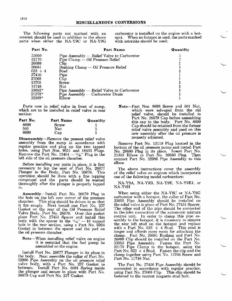
1 8 1 8MISCELLANEOUS CONVERSIONS
The following parts not marked with anasterisk should be used in addition to the aboveparts when either the NA-Y9C or NA-Y9G
carburetor is installed on the engine with a hot-spot. When no hotspot is used, the parts markedwith asterisks should be used:
Quantlty
111111IL1111
Part No.
3305032t70260982668L6 2 3 + 4274L62706813705LL74833052 *21379*32169*
Part Narne
Pipe Assembly - Relief Valve to CarburetorPipe Clamp - Oil Pressure ReliefClipBushing Clamp - Oil Pressure ReliefStudPipeClipScrewNutPipe Assembly - Relief Valve to CarburetorPipe Assembly - Carburetor DrainElbow
Parts now in relief valve in front of sump,which are to be installed in relief valve in rearsection:
Part No.86985018699
Note-Part Nos. 8698 Screw and 501 Nut.which were salvaged from the oldrelief valve, should be installed inPart No. 26678 Cap before assemblingthis cap to the body. Part No. 8699Cap should be retained from the formerrelief valve assembly and used on thisnew assembly after the oil pressure isproperly adjusted.
Remove Part No. 13119 Plug located in thebottom of the oil pressure pump and install PartNo. 26680 Plug in its place. Insert Part No.21352 Elbow in Part. No. 26680 PIug. Thenconnect Part No. 32986 Pipe Assembly to thiselbow.
The above instructions cover the assemblyof the relief valve on engines which incorporateone of the following model carburetors:
NA-Y9A, NA-Y98, NA-Y9E, NA-Y9E1, OrNA-Y9H
When using either the NA-Y9C or NA-Y9Gcarburetor with a hotsnot. the collar of Part No.33050 Pipe Assembly should be installed onthe relief valve in place of Part No. 27457 Spacer.The other end of tha pips should be connectedto the inlet connection of the automatic mixturecontroL unit. In order to clamp this pipe as-sembly to the hotspot, it is necessary to removethe rear left stud on the hotspot and replacewith a Part No. 623 + 4 Stud. This stud islonger and affords more room for attaching theclamp. Part No. 26681 Bushing and Part No.26098 Clip should be installed on the Part No.33050 Pipe Assembly. Fasten the Part No.32170 Pipe Clamp to the hotspot, using thePart No. 623 + 4 Stud. Fasten the clip and theclamp together using Part No. 13705 Screw andPart No. 11748 Nut.
The Part No. 27416 Pipe Assembly should beconnected in accordance with regular practice,using Part No. 27068 Clip. This clip should befastened to the nearest magneto stud bolt.
Part NarneScrewNutcap
Quantlty111
Dlsasserrrbly-Remove the present relief valveassembly from the sump in accordance withregular practice and plug up the two tappedholes, using Part Nos. 9051 and 16433 Plugs.Remove the Part No. 13404 - rYt6" Plug in theIeft side of the oil pressure chamber.
Before installing any parts in place, it is firstnecessary to lap the seat of Part No. 26677Piunger in the Body, Part No. 26676. Thisoperation should be done with a fine lappingcompound and the parts should be washedthoroughly after the plunger is properly lappedln.
Assembly-Install Part No. 26679 Plug inthe hole on the left rear corner of the pressurechamber. This plug should be driven in so thatit fits snugly. Next instali one Part No. 237Gasket on the rear of the Oil Pressure ReliefValve Body, Part No. 26676. Over this gasketplace Part No. 27451 Spacer and install thisbody with the spacer in the tYt6" -- 16 tappedhole in the rear section, using a Part No. 6924Gasket in between the spacer and the pad onthe oil pressure chamber.
Note-When installing relief valve on engineit is essential that the fuel pump beassembled on the engine.
Install Part No. 26677 Plunger in its place inthe body. Next assemble the collar of Part No.32986 Pipe Assembly on the oil pressure reliefvalve body, with a Part No. 237 Gasket inbetween. Install Part No. 6091 Spring insidelhe plunger and secure in place wit=h Pirt No.26678 Cap and Part No. 237 Gasket.
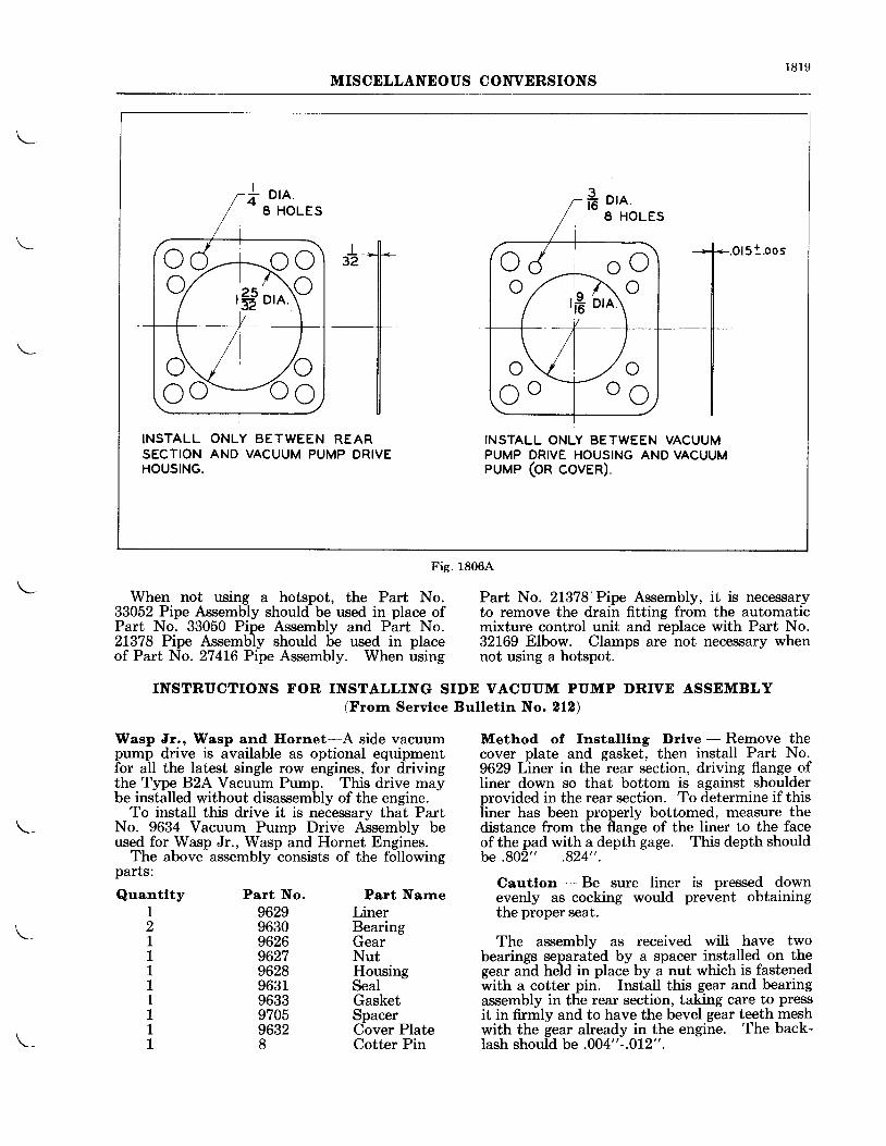
1819MISCELLANEOUS CONVERSIONS
When not using a hotspot, the Part No.33052 Pipe Assembly should be used in place ofPart No. 33050 Pipe Assembly and Part No.2L378 Pipe Assembly should be used in placeof Part No. 27416 Pipe Assembly. When using
Part No. 2L378'Pipe Assembly, it is necessaryto remove the drain fitting from the automaticmixture control unit and replace with Part No.32169 Elbow. Clamps are not necessary whennot using a hotspot.
Method of fnstalllng Drlve - Remove thecover plate and gasket, then install Part No.9629 Liner in the rear section, driving flange ofliner down so that bottom is against shoulderprovided in the rear section. To determine if thisIiner has been properly bottomed, measure thedistance from the flange of the liner to the faceof the pad with a depth gage. This depth shouldbe.802" .824".
Cautlon - Be sure liner is pressed downevenly as cocking would prevent obtainingthe proper seat.
The assembly as received will have twobearings separated by a spacer installed on thegear and held in place by a nut which is fastenedwith a cotter pin. InstaII this gear and bearingassembly in the rear section, taking care to pressit in firmly and to have the bevel gear teeth meshwith the gear already in the engine. The back-lash should be .004"-.012".
INSTRUCTIONS FOR INSTALLING SIDE VACUUM PUMP DRTVE ASSEMBLY(Frorn Servlce Bulletln No. 212)
Wasp Jr., Wasp and Hornet-A side vacuumpump drive is available as optional equipmentfor all the latest single row engines, for drivingthe Type B2A Vacuum Pump. This drive maybe installed without disassembly of the engine.
To install this drive it is necessary that PartNo. 9634 Vacuum Purnp Drive Assembly beused for Wasp Jr., Wasp and Hornet Engines.
The above assembly consists of the followingparts:
Quantlty121111111I
Part No.9629963096269627962896319633970596328
Part NarneLinerBearingGearNutHousingSealGasketSpacerCover PlateCotter Pin
c C - r o oo a r ^ n orfi i'ri
INSTALL ONLY BETWEEN REARSECTION AND VACUUM PUMP DRIVEHOUSING.
INSTALL ONLY BETWEEN VACUUMPUMP DRIVE HOUSING AND VACUUMPUMP (OR COVER).
Fig. 18064
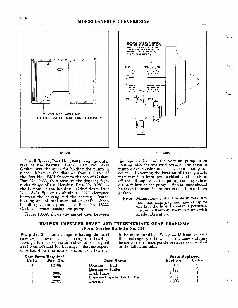
1820MISCELLANEOUS CONVERSIONS
TURN OFF CAGE LIPTO FREE OUTER RACE LONGITUDINALLY.
Fig. 1807
Install Spacer, Part No. 18431, over the outerrace of the bearing. Install Part No. 9633Gasket over the studs for holding the pump inplace. Measure the distance from the top ofthe Part No. 18431 Spacer to the top of Gasket,Part No. 9633, then measure the distance fromunder flange of the Housing, Part No. 9628, tothe bottom of the housing. Grind down PartNo. 18431 Spacer to obtain a .002" clearancebetween the housing and the bearing. Installhousing and oil seal over end of shaft. Wheninstalling vacuum pump, use Part No. 16532Gasket between housing and pump.
Figure 1806A shows the gasket used between
BEARINGS MUST BE ASS€MBL€DWITH HIGH SHOULDERS OF OUTERRACES TOGETHER AS SHol,vN.THESE CAN BE IDENTIFISO BYMARKING ON OUTER RACE,
Fig. 1808
the rear section and "the
vacuum pump drivehousing, also the one used between the vacuumpump drive housing and the vacuum pump- (oriovei;. Reversinglhe location of these gasketsmay result in improper backlash and blan\ingoff-the oil supply to-the pumP, causing srrbsg;quent failure b? Itre p..mp. Siecial care shouldbe taken to insure the proper installation of thesegaskets.
Note-Misalignment of oil holes in rear sec-tion mounting pad and gasket uP toone half the hole diameter is permissi-ble and will supply vacuum pump withample lubrication.
to be more durable. Wasp Jr. B Engines havethe steel cage type blower bearing cage and maybe converted toincorporate bearings as describedin the following table:
BLOWER IMPELLER SIIAFT AND INTERMEDIATE GEAR BEARINGS(Frorn Servlce Bulletln No. 214)
Wasp Jr. B - Latest engines having the steelcage type blower bearings incorporate bearingshaving a formica separator instead of the originalPart Nos. 103 and 105 Bearings. Service experi-ence has shown formica separator type bearings
New Parts RequlredUnlts Part No.
4 12768
1 90351 9036L 12769
Part NarneBearing BalIBearing - RollerLock PlateCage - Impeller Shaft Brg.Bearing
Parts ReplacedPart No, Unlts
103105
5020
221
5022 15028 1
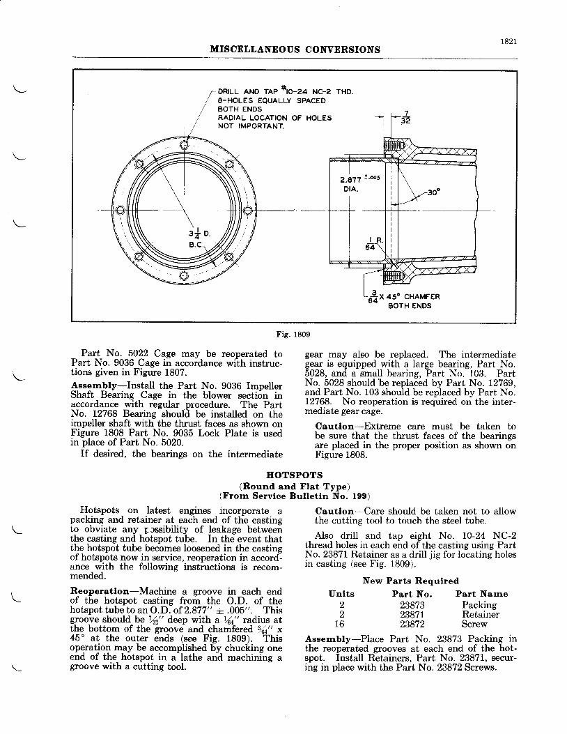
r82lMISCELLANEOUS CONVERSIONS
Part No. 5022 Cage may be reoperated toPart No. 9036 Cage in accordance wilh instruc-tions given in Figure 1807.A_ssernbly-Install the Part No. 9036 ImpellerShaft Bearing Cage in the blower section inaccordance with regular procedure. The PartNo. 12768 Bearing should be installed on theimpeller shaft with the thrust faces as shown onFigure 1808 Part No. 9035 Lock Plate is usedin place of Part No. 5020.
If desired, the bearings on the intermediate
Fig. 1809
EOTSPOTS(Round and FIat Type)
(Frorn Servlce Bulletln No. 199)
Unlts22
16
gear may also be replaced. The intermediategear is equipped with a large bearing, Part No.5028, and a small bearing, Part No. 103. PartNo. 5028 should be replaced by Part No. 12769,and Part No. 103 should be replaced by Part No.12768. No reoperation is required on the inter-mediate gear cage.
Cautlon-Extreme care must be taken tobe sure that the thrust faces of the bearingsare placed in the proper position as shown onFigure 1808.
Hotspots on latest engines incorporate apacking and retainer at each end of the castingto obviate any p rssibility of leakage betweenthe casting and hotspot tube. In the event thatthe hotspot tube becomes loosened in the castingof hotspots now in service, reoperation in accord-ance with the following instructions is recom-mended.
Reoperatlon-Machine a groove in each endof the hotspot casting from the O.D. of thehotspot tube to an O.D. of 2.877" + .005". Thisgroove should be 7/s2" deep with a %t" radius atthe bottom of the groove and chamfered lAt" x45" at the outer ends (see Fig. 1809). Thisoperation may be accomplished by chucking oneend of the hotspot in a lathe and machining agroove with a cutting tool.
Cautlon-Care should be taken not to allowthe cutting tool to touch the steel tube.
Also drill and tap eight No. 10-24 NC-2thread holes in each end of the casting using PartNo. 23871 Retainer as a drill jig for locating holesin casting (see Fig. 1809).
New Parts RequiredPart No. Part Narne
23873 Packing23871 Retainer23872 Screw
Assernbly-Place Part No. 23873 Packing inthe reoperated grooves at each end of the hot-spot. Install Retainers, Part No. 23871, secur-ing in place with the Part No. 23872 Screws.
a DR|LL AND TAP *tO-Za NC-z THD.i 8-HOLES EQUALLY SPACED
BOTH ENDSRADIAL LOCATION OF HOLESNOT IMPORTANT.
*1l
7sZ
?.g77 ! 'oo5
DIA.
l
f-
r822MISCELLANEOUS CONVERSIONS
MAIN OIL SCREEN(Frorn Service Bulletin No. 208)
Installatlon of Sprlng Loaded Check Valve registered in the pressure system. On stoppingin Wasp Hl and HlrnJt E Englnes-In certain th"e engine and ivith the resultant loss of oilinstalhtlions where the oil tanf, is located some press,tr6, the spring loaded valve closes, thusdistance above the engine and the airplane is preventing any oil seeping through the pressureallowed to stand a con"siderable length bf time, brr*p from going beyond this check valve.oil may seep from the tank through the pressure The oil screen and check valve assembly ispump into- the crankcase and . cylinders._ To directly interchangeable with the plain gil screenprevent- this,-a main oil- screen incorporating.a formeriy used. T-he plain oil screen will be con-spring- loaded check valve is now installed ir1 tinued is a replacement part for those customersthe subject engines. This check valve is forced who may desire them for engines shipped prioropen as soon as an appreciable oil pressure is to this change.
One-Plece Type Otl Screen and Check Valve Assernbly
Parts RequlredUnlts Part Nc.
1 4-23435Part Narne
Ring - Oil SealOil Screen Assembly (one-piece)Seat ValveValveSpringNut
No. 23215
Parts RernovedPart No. Unlts
8-6075 1tII11
B-22545A-22897A-22895A-22896A-501
FLOATING GEARS(Frorn Servlce Bulletln No. 287)
Hornet E and E-G-BeginningwithEngineNo. If it is desired to replace the Part No. 1367029LL, ali- Hornet enginls incorporate hoating Floating Gear bv thq new, type ea{ }9 !!I1lgears and blower intermediat" "orrnt"r.hufT l::'iig-
Gear' the p.rgsenq' blower intermedtate
gears having the Felrows type r,r'u,p"tiofil gi;J"e"fftf{: ffi#ol{":ttlt3;:"nffi"1il};t#;teeth in place of the stub type. This will insure lear and shaft assembly. The following^ is agreater wear characteristics due to greater over- iist of blower intermediate geql and sha& as-
Lp of the teeth. semblies used with Part No. 74134 Floating Gear:
Part No. Part Narne Blower Ratlo
17232 Blower Intermediate Gear and Shaft Assembly t2:l19477 Blower Intermediate Gear and Shaft Assembly 10:126L45 Blower Intermediate Gear and Shaft Assembly 8:118693 Blower Intermediate Gear and Shaft Assembly 11:126147 Blower Intermediate Gear and Shaft Assembly 13:1
Note-The proper assembly to be used should be determined by the blower ratio desired.
IMPROVED TYPE REAR SECTION(Frorn Servlce Bulletln No. 220)
Wasp Jr. B, Wasp Hl and Ifornet E-The On Wasp Jr. B rear sections,.the flow of oillatest models of th-e above engines have a re- through th-e oil strainer chamber is go-w changeddesigned rear section which chaiges the location from -'inside out" to "outside in" oil flow.of the oil pressure relief valve from the left sideof the strainer chamber to the right side of the A new type oil--pump must be used with thecrankcase. The reliefl valve rout"es the relieved rear section-to utifize the new relief valve posi-oil to the inlet or suction side of the oil pump tion. The new rear section may be used inthrough an internal cored passage. Thii rear engines- now in service without changing the, oilsectioi also incorporates a n^ew tipe oil strainer pulnp by_plugging an_oil pqssage. as describedhaving a check valve as described under the below. When this is done, the relief valve can-heading "Main Oil Screen" in this chapter. not be used in the new position.
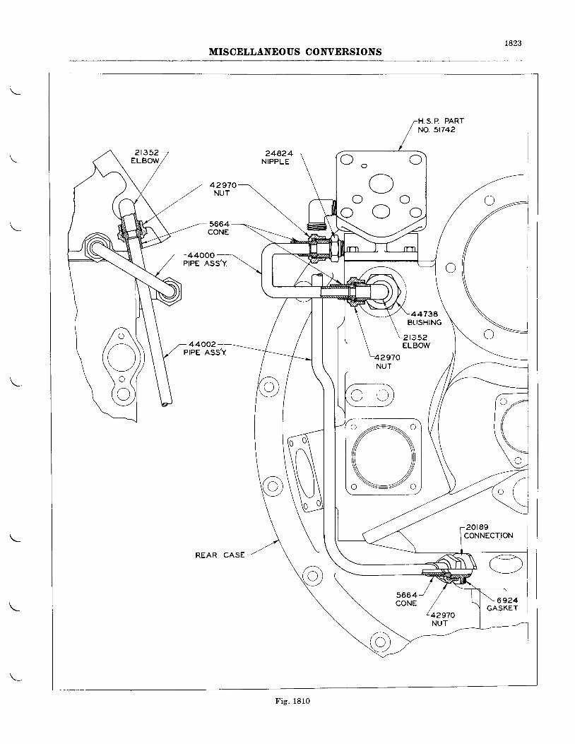
t823MISCELLANEOUS CONVERSIONS
H.S.P. PARTNO. 5t742
248.24NIPPLE
42970NUT
5664CONE
CONNECT.ION
REAR CASE
6924
r-)\ J O
r^) (,(,
r )
I I
44000
44002
GASKET
Fig. 1810
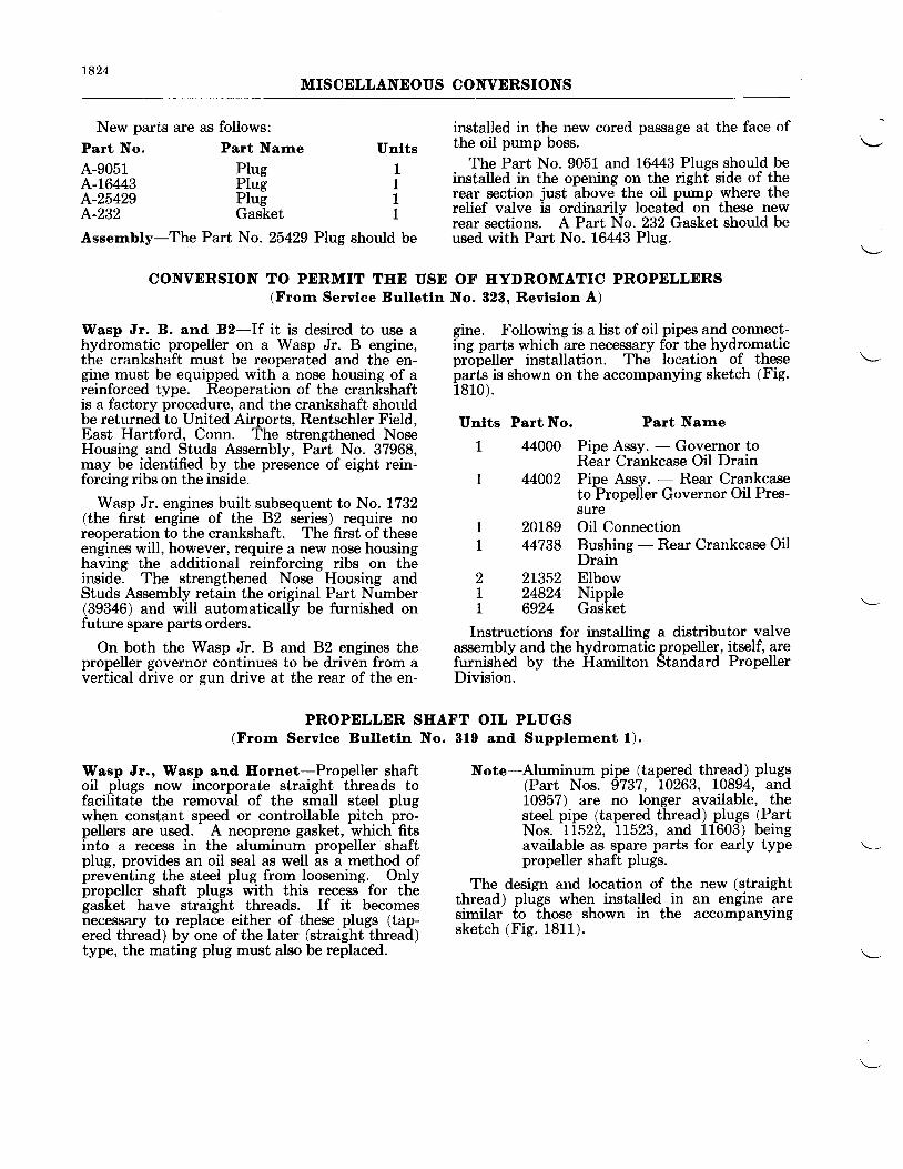
1824MISCDLLANEOUS CONVERSIONS
New parts are as follows:Part Narne
PlugPlugPlugGasket
Assernbly-The Part No. 25429 Plug should be
CONVERSION TO PERMIT TEE USE OF IIYDROMATIC PROPELLERS(Frorn Servlce Bulletln No. 828. Revlslon A)
Part No.
4.-9051A-16443A-25429A-232
Unlts1111
Wasp Jr. B. and B2-If it is desired to use ahydromatic propeller on a Wasp Jr. B engine,the crankshaft must be reoperated and the en-gine must be equipped with a nose housing of areinforced type. Reoperation of the crankshaftis a factory procedure, and the crankshaft shouldbe returned to United Airports, Rentschler Field,East Hartford, Conn. The strengthened NoseHousing and Studs Assembly, Part No. 37968,may be identified by the presence of eight rein-forcing ribs on the inside.
Wasp Jr. engines built subsequent to No. 1732(the first engine of the 82 series) require noreoperation to the crankshaft. The first oftheseengines will, however, require a new nose housinghaving the additional reinforcing ribs on theinside. The strengthened Nose Housing andStuds Assembly retain the original Part Number(39346) and will automatically be furnished onfuture spare parts orders.
On both the Wasp Jr. B and 82 engines thepropeller governor continues to be driven from avertical drive or gun drive at the rear of the en-
Wasp Jr., Wasp and Ilornet-Propeller shaftoil plugs now incorporate straight threads tofacilitate the removal of the small steel plugwhen constant speed or controllable pitch pro-pellers are used. A neoprene gasket, which fitsinto a recess in the aluminum propeller shaftplug, provides an oil seal as well as a method ofpreventing the steel plug from loosening. Onlypropeller shaft plugs with this recess for thegasket have straight threads. If it becomesnecessary to replace either of these plugs (tap-ered thread) by one ofthe later (straight thread)type, the mating plug must also be replaced.
installed in the new cored passage at the face ofthe oil pump boss.
The Part No. 9051 and 16443 Plugs should beinstalled in the opening on the right side of therear section just above the oil pump where therelief valve is ordinarily located on these newrear sections. A Part No. 232 Gasket should beused with Part No. 16443 Plug.
gine. Following is a list of oil pipes and connect-ing parts which are necessary for the hydromaticpropeller installation. The location of theseparls is shown on the accompanying sketch (Fig.1810) .
Unlts Part No. Part Name
PROPELLER SHAFT OIL PLUGS(Frorn Servlee Bulletln No. 8lg and Supplernent l).
1 44000 Pine Assv. - Governor toRdar Crankcase OiI Drain
1 44002 Pipe Assy. - Rear Crankcaseto?ropelier Governor Oil Pres-sure
1 20189 Oil ConnectionI 44738 Bushing - Rear Crankcase Oil
Drain2 2L352 Elbow| 24824 NippleL 6924 Gadket
Instructions for installing a distributor valveassembly and the hydromatic propeller, itself, arefurnished by the Hamilton Standard PropellerDivision.
Note-Aluminum pipe (tapered thread) plugs(Part Nos. 9737, 10263, 10894, and10957) are no longer available, thesteel pipe (tapered thread) plugs (PartNos. 11522, LL523, and 11603) beingavailable as spare parts for early typepropeller shaft plugs.
The design and location of the new (straightthread) plugs when installed in an engine aresimilar to those shown in the accompanyingsketch (Fig. 1811).
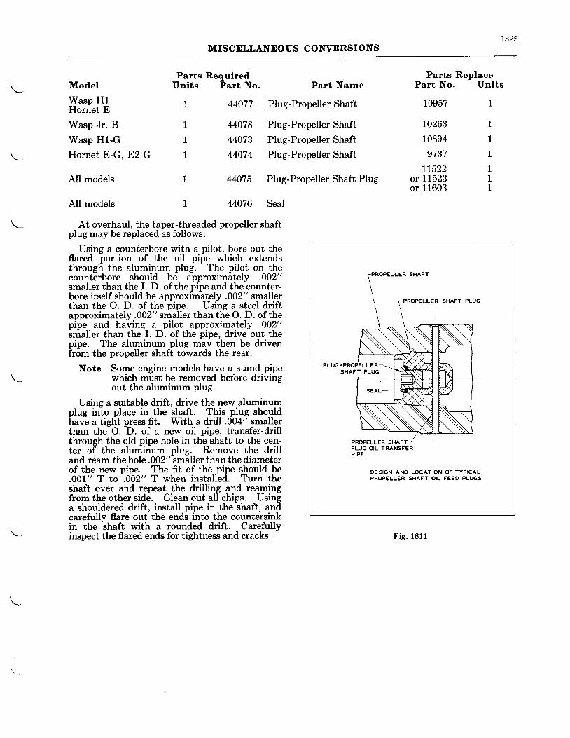
1825MISCELLANEOUS CONVERSIONS
Model
Wasp H1Hornet E
Wasp Jr. B
Wasp H1-G 1
Hornet E-G. E2-G 1
AII models
AII models
| 44077 Plug-Propeller Shaft
L 44078 Plug-Propeller Shaft
44073 Plug-PropellerShaft
44074 Plug-PropellerShaft
44075 Plug-Propeller Shaft Plug
44076 Seal
Parts RequlredUnits Part No. Part Narne
Parts ReplacePart No. Unlts
10957 1
10263 1
10894 1
9737 1
tL522 1or L1523 Lor 11603 1
At overhaul, the taper-threaded propeller shaftplug may be replaced as follows:
Using a counterbore with a pilot, bore out theflared portion of the oil pipe which extendsthrough the aluminum plug. The pilot on thecounterbore should be approximately .002"smaller than the I. D. of the pipe and the counter-bore itself should be approximately .002" smallerthan the O. D. of the pipe. Using a steel driftapproximately .002" smaller than the O. D. of thepipe and having a pilot approximately .002"smaller than the I. D. of the pipe, drive out thepipe. The aluminum plug may then be drivenfrom the propeller shaft towards the rear.
Note-Some engine models have a stand pipewhich must be removed before drivingout the aluminum plug.
Using a suitable drift, drive the new aluminumplug into place in the shaft. This plug shouldhave a tight press fit. With a drill .004" smallerthan the O. D. of a new oil pipe, transfer-drillthrough the old pipe hole in the shaft to the cen-ter of the aluminum plug. Remove the drilland ream the hole .002" smaller than the diameterof the new pipe. The fit of the pipe should be.001" T to .002" T when installed. Turn theshaft over and repeat the drilling and reamingfrom the other side. Clean out all chips. Usinga shouldered drift, install pipe in the shaft, andcarefully flare out the ends into the countersinkin the shaft with a rounded drift. Carefullyinspect the flared ends for tightness and cracks.
DESIGN AND LOCATION OF TYPICALPROPELLER SHAFT OIL FEED PLUGS
Fig . 1811
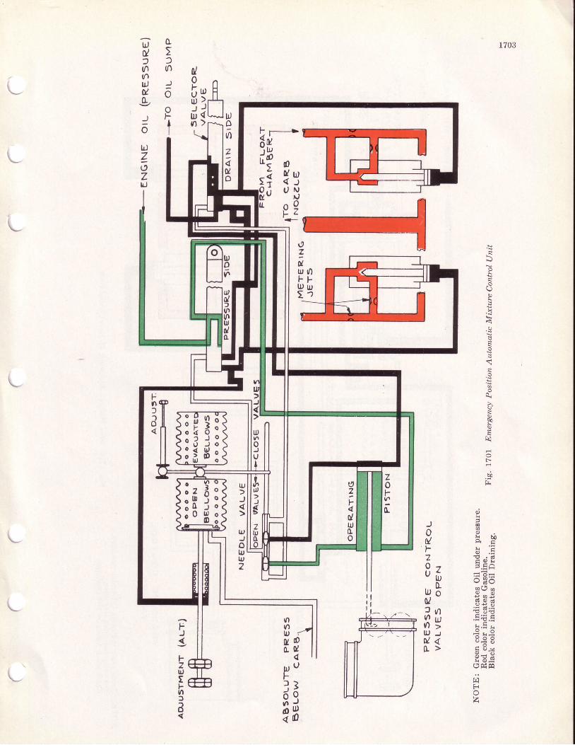
1703
0/0
I id j
9 g2 )n r )nu r )
E ooTo
tdZozld
ldIril
z4go
L
L\v
>:
psrl
E
R
{
a
$sstq
r.-
il
\,7ilu t OF FI D Ut "
gr A/ \ x (i l E * ,
b -, i i x- ,
€ . d
5 , E.HA' "6 B?Bqb e?su S $ g
in : t=v ' > h ' r *l lJ J i r€D l < u * 8t r> f i : t
H 6 gopltr
r,iErA
z
od
u
3oJIDa
U)t1luu0,
u,Ff)ooo
u,
)
tr,
olr,IU2
5FzllJtFvlfa
L
L
Fnf
a
zot-vr
0.
t,7F4du,tro
!--r I
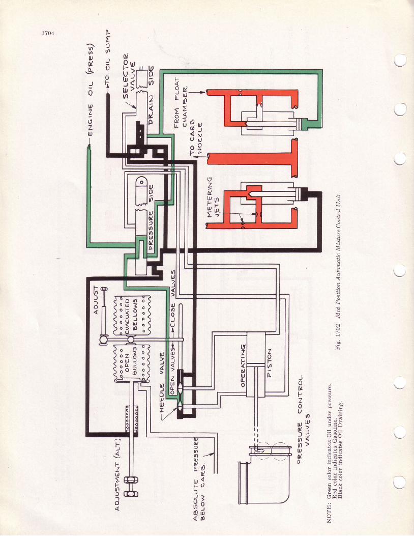
ItJ
un
J0
I704
G.. ou,ug
J0
t
7t,zll,
l-
49 i lrHE iu tI L U
l,oa
2il
ot9 trt[ ]
t 9o
5
rX
p{8
E
F-.l
h0
('zdlrJt-tr,t
Jou gF A', *,6 E . Pu , - U : Eu , l J E g AE >. !+=1 ) x d =
n{ sg$tq 8E Iu € 3 EIL .EE.E
F { . = !"g .g8 * eg U .v
Hr-Er h d m
triFi
z
IIt_
I1
totll)z
00l4t,
70luo
o/?u'lttlUJuI
tl,rlJ0tflo
e4
v-7t,tFu1)-,o4
fsl*l ru
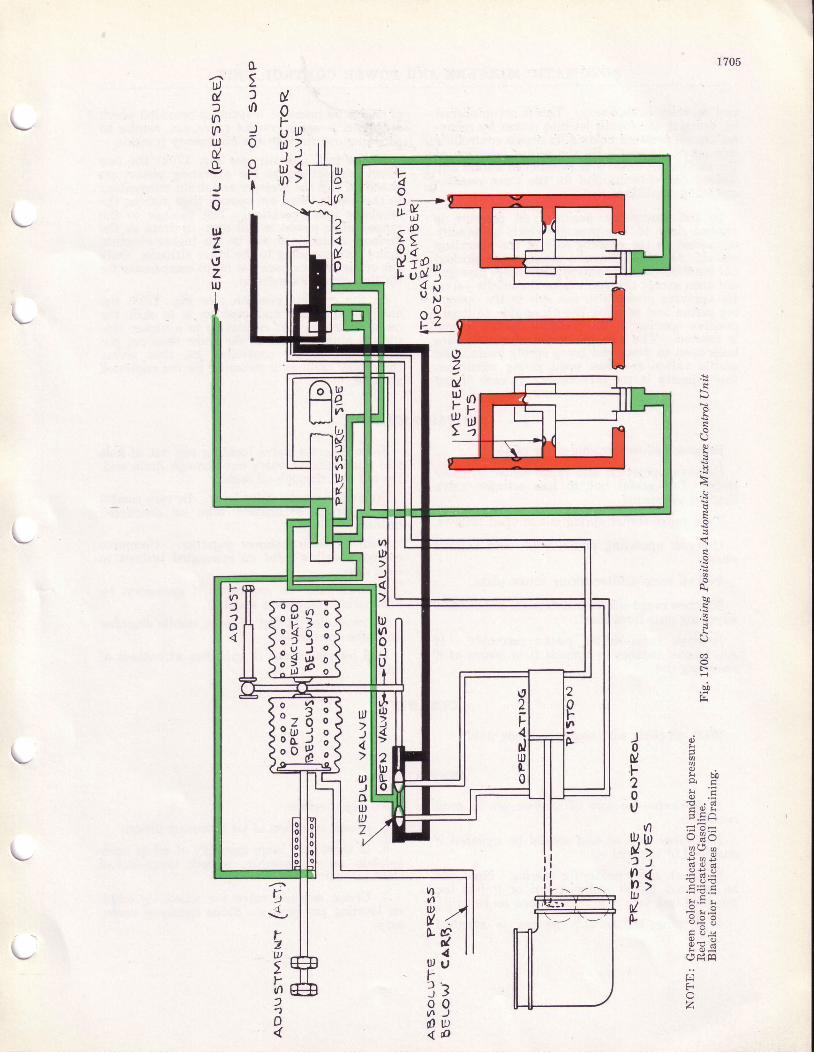
1705
luItf
?
dIb ttrr l ?r )
i l 4rn>
o5foJ6
PtI
u)d)nnuldo
!0ulzrtzIU
\v
rX
p
B
E
{
6
D0
(D
F-
b!,F
d i i0 / ^. F 3 i ^ ;2 P' .;'0 b . E. r ' d . 6 1v E.HA
{1 =7=ttl, ttl o,e'Ox? s ; g?i xf ;xn > ; . ; Eltr ': E'-et ^q I-Er 3 € 8
tr e-Y3"o H
r F p mV H H
triFa
z
IIII
I
|f.r
E4u:70)u)a
I?o/He? e
tsood r-*5 g
PfsiP 2
vttlu,9/0-
[urfJooo{
L
u,)4
u,)olt,az
,{.,
rzw,Y^
)1o
F(n)1o
tt2
idluL0
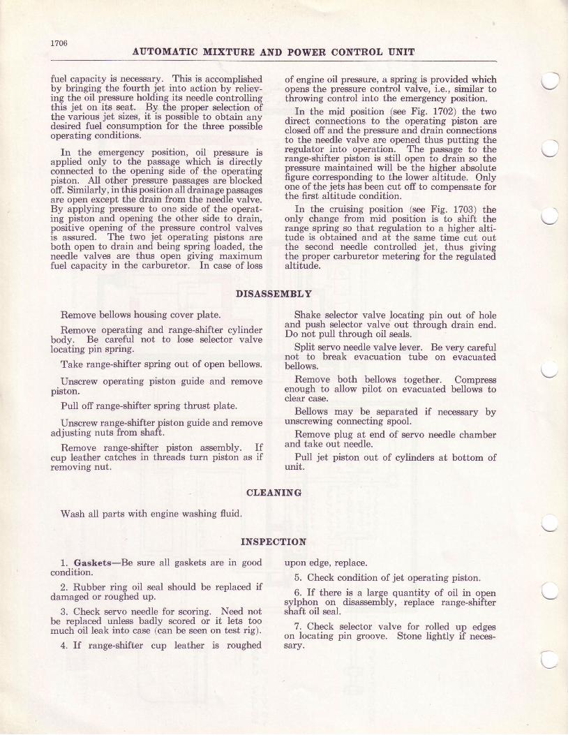
1706AUTOMATIC MIXTURE AND POWDR CONTROL UNIT
fuel capacity is necessary. This is accomplishedby bringing the fourth jet into action by reliev-ing the oil pressure holding its needle controllingthis jet on its seat. By the proper selection ofthe various jet sizes, it is possible to obtain anydesired fuel consumption for the three possibleoperating conditions.
In the emergency position, oil pressure isapplied only to the passage which is directlyconnected to the opening side of the operatingpiston. All other pressure passages are blockedoff. Similarly, in this position all drainage passagesare open except the drain from the needle valve.By applying pressure to one side of the operat-ing piston and opening the other side to drain,positive opening of the pressure control valvesis assured. The two jet operating pistons areboth open to drain and being spring loaded, theneedle valves are thus open giving maximumfuel capacity in the carburetor. In case of loss
DISASSEMBLY
Remove bellows housing cover plate.
Remove operating and range-shifter cylinderbody. Be careful not to lose selector valvelocating pin spring.
Take range-shifter spring out of open bellows.
Unscrew operating piston guide and removepiston.
Pull off range-shifter spring thrust plate.
Unscrew range-shifter piston guide and removeadjusting nuts from shaft.
Remove range-shifter piston assembly. Ifcup leather catches in threads turn piston as ifremovrng nut.
CLEANING
Wash all parts with engine washing fluid.
INSPECTION
1. Gaskets-Be sure all gaskets are in goodcondition.
2. Rubber ring oil seal should be replaced ifdamaged or roughed up.
3. Check servo needle for scoring. Need notbe replaced unless badly scored or it lets toomuch oil leak into case (can be seen on test rig).
4. If range-shifter cup leather is roughed
of engine oil pressure, a spring is provided whichoperur the pressure control valve, i.e., similar tothrowing control into the emergency position.
In the mid position (see Fig. U02) the twodirect connections to the operating piston areclosed off and the pressure and drain connectionsto the needle valve are opened thus putting theregulator into operation. The passage to therange-shifter piston is still open to drain so thepressure maintained will be the higher absolutefigure corresponding to the lower altitude. Onlyone ofthe jets has been cut off to compensate forthe first altitude condition.
In the cruising position (see Fig. 1703) theonly change from mid position is to shift therange spring so that regulation to a higher alti-tude is obtained and at the same time cut outthe second needle controlled jet, thus givingthe proper carburetor metering for the regulatedaltitude.
Shake selector valve locating pin out of holeand push selector valve out through drain end.Do not pull through oil seals.
Split servo needle valve lever. Be very carefulnot to break evacuation tube on evacuatedbellows.
Remove both bellows together. Compressenough to allow pilot on evacuated bellows toclear case.
Bellows may be separated if necessary byunscrewing connecting spool.
Remove plug at end of servo needle chamberand take out needle.
Pull jet piston out of cylinders at bottom ofurutr.
upon edge, replace.
5. Check condition of jet operating piston.
6. If there is a large quantity of oil in opensylphon on disassembly, replace range-shiftershaft oil seal.
7. Check selector valve for rolled up edgeson locating pin groove. Stone Iightly if neces-sary.
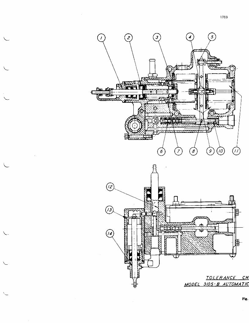
1713
TOLERANCE CH,
MODEL 3/05- 8 AL'TOMATIC
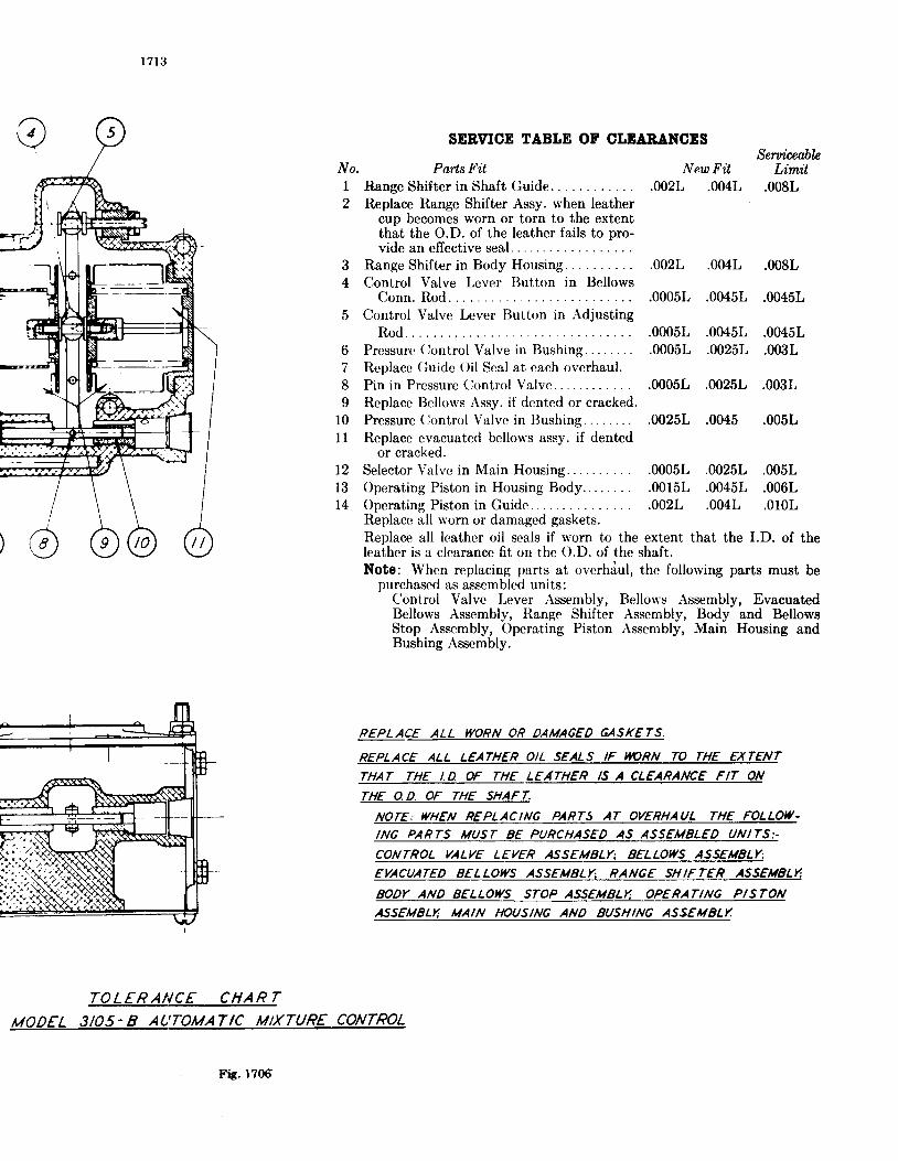
1 713
TOLERANCE CHART
MODEL 3/05-8 AUTOMATTC MlXTUR€ CONTROL
SERVICE TABLE OF CLEAA,ANCESSeniceobln
Parts Fit New Fit LimitRange Shifter in Shaft Guide. .002L .004L .008LReplace Range Shifter Assy. when leather
cup becomes worn or torn to the extentthat the O.D. of the leather fails to pro-vide an effective seal...
3 Range Shifter in Body Housing. .002L .004L .008L4 Control Valve Lever Button in Bellows
Conn. Rod. .0005L .0045L .0045L5 Control Valve Lever Button in Adjusting
Rod. . . .0005L .0045L .0045L6 Pressurc (iontrol Valve in ISushing. .0005L .0025L .003L7 Replacc Guidc Oil Scal at each overhaul.8 Pin in Prcssure (lontrol Valve. .0005L .0025L .003L9 Replace IJell<-rrvs Assy. if dented or cracked.
l0 Pressure (jontrol Valvc in Bushing. .0025L .0045 .005L11 Replace evacuatcd bellows assy. if dented
or cracked.Selector Valvc in Main HousinC..... . . . . . .0005L .0025L .005LOperaiing Piston in Housing Body.. . . . . . . .0015L .0045L .006LOperating Piston in Guide. .002L .004L .010LReplacc all worn or damaged gaskets.Replace all leather oil seals if w<lrn to the extent that the I.D. of theleather is a clearancc fit on the O.D. of the shaft.Note: Whcn replacing parts at ovcrhdul, the follorving parts must be
purchased as assembled units:Control Valve Lever Assembly, Bellou's Assembly, EvacuatedBellows Assembly, Ilange Shifter Assembly, Body and BellowsStop Assembly, Operating Piston Assembly, Main Housing andBushing Assembly.
REPLACE ALL WORN OR DAMAGED GASKETS.
REPLACE ALL L€ATH€R OIL SEALS IF NARN TO THE EXTENT
THAT THE I.D. ff THE LEATHER IS A CLEA.RANCE FIT ON
rHE O.D. OF THE SHAFT.
NOTE. WHEN REPLACING PARTS AT OVERHAUL THE FOLLOIy.ING PARTS MUST 8E PURCHASED AS ASSEMELED UNITS:.
CONTROL VALVE LEVER ASSEMBLYT EELLOWS ASSELIELY;
EVACUATED EELLOI(S ASSEMELY., RANGE SHIFTER ASSEUELT'
EODY AND EELLOWS STOP ASS.EMSLTI OPERAT|NG PTSTONASSEUELIi UAIN IIOUSING AND SUSHING ASSEMELT
No.I2
t2l3l4
Fis .1706
INSTRUCTIONS FOR STROMBERG NA.YgE ANI)
1317
NA.YgET CARBURETORS
OVEREAIIL
I)lsassembly-The carburetor should be dis-assembled for cleaning and inspection each timethe engine is given an overhaul. After thecarburetor has been removed from the engineand the hot spot and air intake or heater takenoff, the halves o{ thg carburetor may be separatedby the removal of the fi"llister head screws atthe parting surface. The economizer needle,pump sleeve and venturii are held in the throttlebody as the _bodies are separated. The pumpsleeve should be removed- from the opeiatingstem immediately so there will be no dinger oTits dropping and becoming bent. Rubber
-pack-
ing is used around the venturii so that if it isfound necessaq/ to remove them, they will haveto be driven out by using a wooden plug asshown in tr'ig. 1310-4. Before removing-thethrottle valves, mark them so they may be re-turned to the barrels from whici th6y wereremoved. It should not be necessarv to removethe idle discharge jet assemblies uniess some ofthese parts should be replaced. The main bodyparts may all be removed.
Inspectlon and Cleanlng-The bodies andall parts should be thoroughly cleaned in gasolineand all passages blown out with compressed air.Parts which should be inspected foi wear arethe float assembly, float needle and seat, throttleshaft and bushings, economizer needle, seat andoperating mechanisms and the pump stem. Allvariable parts should be checked to see that theirsizes are in accordance with the carburetor specifi-cation desired.
To disassemble the compound pump unit (seeFig. 1311) it should be removed from the operat-ini stem ind the four small hexason head dcrewswf,ich hold the stem clip in phc:e should be re-moved. The connecting rod between the upperand lower piston is milled flat above the crosshole, so it can be held with a wrench when re-moving the center scfews. Considerable forcewill be required to loosen the center screw as ithas been staked in place as a precaution againstits coming loose in service. When the centerscrew has been removed the upper piston may belifted out ofthe sleeve and the connecting rod andlower piston can be removed through the bot-tom of the sleeve. Care should be taken thatnone of the parts are damaged during disassem-bly or assembly as they are made to fit with veryclose tolerances and a small nick or dent mightcanse a binding action.
Replaoements-When ordering replacementparts it is necessary to give complete informationconcerning the parts desired to avoid delay inshipment or the receipt of wrong parts. Where-ever possible, the serial number of the carbu-
retor should be given. A careful reference tothe assembly drawings (see Figs. 1312 and 1313)to determine the correct part number and name,and if marked with an asterisk (*) giving thesize as stamped on the piece will greatlyfacilitate service. A specifiiation sheet givin-gthe sizes_ gf jets, fuel level, economizer selting,etc., will be furnished (no charge) if you wiiiwrite to the Bendix ProductJ Corforation,Stromberg Carburetor Division, South Bend,Indiana, advising the model of your engine.Parts price lists will also be furnished on request.P-2L463 covers a complete set of gaskets forthe NA-Y9E and P-60524 for the NA-Y9E1.
Reassembly-All headless screw plugs belowthe fuel level should be assembled with shellac.being careful not to get it on the end of the plugwhere it will come off and be carried by the fuelinto one of the metering orifices. Headlessscrew plugs above the fuel level and aII otherthreaded parts screwed into the bodies shouldhave a compound of graphite and castor oil puton the threads.
When it is necessary to replace the throttleshaft, the lever which operates the economizershould be assembled in accordance with Fig.1310-8. The throttle valves, when in the closedposition, should fit tightly. When the throttlevalves have been fitted, center them in the wideopen,position. If the economizer operating leverhas been assembled at the correct angle thethrottle valves should be centered. However.when this work is done in the field it mav b6necessary to file the stop at A, Fig. 1310-8, orbend it toward the screwed-in stop.
If it is thought necessary to replace a floatneedle or needle seat it is recommended thatbqlh !,e replaced at the same time as it is verydifficult to fit a new needle to an old seat or anew seat to an old needle. In ordering thesepalts, be sure to give the size of the by-passholes in the float
-needle seat. These by-bass
holes meter the fuel during inverted flight -and
their size has been determined to meet the re-quirement of that particular engine and it is,therefore, important that a seat having the propersize by-pass holes be used for replacement pur-poses.
The float level should be ry'", plus or minusYe" below the parting surface, and is dependentupon the thickness of the gasket under the floatneedle seat. The level should be checked underthe conditions encountered in service as regardsthe fuel used and the fuel pressure or head atthe carburetor. If a fuel pump is used. a pre$sureat the carburetor of 3 lbs-. per square incir 11U"
1318CARBURDTORS
gaso-line at .!10 sp. gr,) shouldbe used in checkingthe fuel level. A gasket %2" tbickshould be useiifirst and if the level is not correct use thickergaskets to lower the level and thinner gasketsto raise it. A change of ,(4" gasket ttricknesswill change the level approximately %r". Thefloat needle should have at leaet/6a" travel.
If it becomes necessary to replace the mixturecontrol shaft or stop it is important that thestop be located in the conect angular positionon ihe shaft. In order to do this.-place^a smallpiece of wood in the slot of th'e'outer valveplgle in such a-way that it extends through andwill fit in the slot of the inner plate. Place theouter valve plate ln the carburitor in the open-ing position and the wood key will keep it flomturning. Place the shaft and bushing assemblyin the carburetor, adjusting the shAft so tliescrew driver ends fit into the valve, and put inthe screws to hold the bushings in place. Slipthe washer and stop on the shift and turn untilthe full rich stop is against the large head screw.Assemble lever, indicator plate and nut on theshaft. Draw nut up until washer strikes shoulderon qhaft. drill and fit pin through stop andshaft. (See assembly draryrng (Ffr. 1312) forsection and end view of shaft assembly.)
The economizet needle is operated bv an ec-centric pin which is part of thi economiier leverstem. This stem is operated by the throttlethrough two levers and a connecting link. It isimportant that the economizer lever be locatedat the ploper angle with the eccentric pin on theeconomizer lever stem.
When replacing the economizer lever stemuse a new economizer lever also. The levershould be assembled so that its cetlter line formsa 90 degree angle with the cent€r line of theeccentric pin as shown in Fig. 1310-D. Whenthe lever fqs.leen properly set, tighten the clampscrew and drill stem and one sideof lever for ttielocating pin. Screw pin into place.
The adjustment of the economizer needlevalve in the holder and the eccentric pin on thelever determine the position of the l6ver whenthe needle is on the seat and. therefore. thethrottle opening at which the lever lifts off theseat. This throttle opening is one of the itemsof the variable specifications or setting in thecarburetor and is given on the spec:fficationsheet, being referred to as "economizer setting",the figure give! being the throttle opening indegrees. By adding 20 or 18 (the angle of the
throttle valve) to this figure the angle which thethrottle valve makes with the horizontal sur-face of the carburetor is obtained.
Several economizer settings are in use andthe proper one should be determined from thecarburetor spec-ification sheet. The first adjust-ment is made by screwing the needle in or outof the holder so that when placed in the mainbody the distance from the-top of the slot tothe parting surface will be in accordance withthe dimensioru as shown in Fig. 1310-C for theeconomizer setting desired. When this has beendone, tighten the nut and pin the needle as perthe instructions given in Fig. 1310-C. The twohalves should then be assembled and final ad-justment made by means of the eccentric on theeconomizer lever. Check the angle between thethrottle and the horizontal surface of the carbu-retor flange when the needle starts to leave theseat. A simple apparatus to check when thismovement starts is shown in Fie. 1310-E. It ismade by drilling a hole througli- the center of a%6"-18 plug,large enough to allow the free move-ment of a piece of tubing about 4" Iong. Thenby _taking 9ut the- economizer metering jet plugand jet it 19 pos,sible to screw in the other plugand push the tubing up so that it rests on thepoinl of lhe qe_edlg. If a slight pressure is puton the tube with the fingers while the throttlb ismoved,lhe ulseating of the needle will be easilydetected. Adjust the eccentric until the conectangle is obtained. When the adjustment hasbeen made, tighten the nuts, being careful not tomove the eccentric, and assemble the cotter pins.
When reassembling the compound pump unit,considerable care shbuld be t-aken sb tfr'at ttriparts will be concentric to each other and thenchecked in the body to see that it works freelybefore restaking the center screw which hold'sthe piston in place. The small hexagon screwsshould be safety wired after tightening. Whenassembling the upper sleeve and piston into thesleeve fastened in the body, considerable careshould be taken so the leather will not be curledup around the piston. The leather should bewet with gasoline and one side assembled in thesleeve, then as the piston is forced into thesl@ve, it should be rbtated so the leather willgo into the sleeve evenly. With the throttleyalves open the operating stem may then behooked in place or the purnp unit arid the twohalves of the carburetof ass^embled together inthe usual manner.
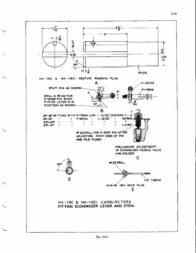
1319
br19
30'-T-wooD
N A - Y g E & N A - Y 9 E I VENTURI REMOVAL PLUG.
ASPLIT PIN AS SHC
DRILL & REAM FORP'I9O66 PIN WHENP-20t36 LEVER tS tNPOS|TtON AS SHOWN.
t6c-t8c SETTING WITH P-17684 LINKt9-2F P-160042 ? . _ 2 5 c r , ' r t26c-3lc
| - i l /32"CENTERS I' j)- tu32"
,T52DRILL FOR P-6587 PIN AFADJUSTINC. RIVET ENDS OF PINAND FILE FLUSH.
PRELIMINARY ADJUSTMENTOF ECONOMIZER NEEDLE VALVEAND HOLDER.
c
HEX. HEAD
E
N A - Y g E & N A . Y 9 E IFITTII.IG ECONOMIZER
C A R B U R E T O R SLEVER AND STEM.
Fig. 1310
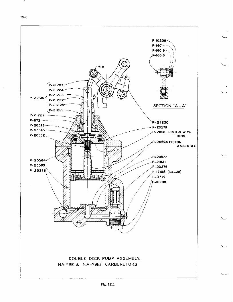
1320
ft-l P -
,-rtrroff,_
l e -tP-
212072t?242t226
212222t223
2t223sEcTloN 'A - A"
P-2t229P-6721 2t230P- 20578P- 20595
P-205E2
P- 20579P- 20581 PISTON WITH
R I N G .
P-20594 PTSTONASSEMBLY
P:20577P-2183rP-20576P-r7rss (tt+-za)
-3779-r090E
DOUBLE DECKNA-YgE & NA-YgEI
PUMP ASSEMBL\ .CARBURETORS
Fig. 1311
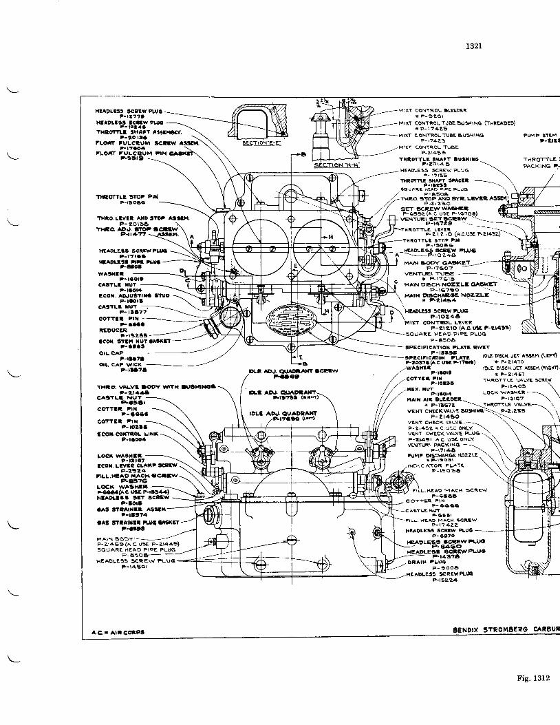
t32L
XT CONTROL BLEEDERx P - 9 e O r
Mlxr coNTRoL TUBE DusH\Nq (THREADED)xP- t7425
-MIXT CONTROLTUBE AUSHINGP-20 l t3FLO'T FVLCEUII
P-t"ao4
HtADLt3t SCatW rtu(l?-ra'l'lt
Hlaorttt Ecarw Purct- to2 ae
TXEOTTLI !tHAF' Et'Ei4OLY.
SCarrv'LOAI TULCQUM PIX
Ft9t9 .-
T}ICOYTLE gTOP PIXP-ls06c
THIO.LTVER AtaD t"Ot A3tt',l.P - 201a6
T|IEG|. AD.r, tiltlPP-n+Tf -
HEADLES|3 SCREW PLUIP - l t t 6 t
HtaDutt P|rt rl.|,l.Ftaot
?-aaaa'IEDUCER
F-r!2E3lcoil.3r3n xutOatxrl-
P . O l O l
OIL CAPP-ltrtt
orl. cAP wlcx
CA3TLI NUTFCETI
ccflTlt trilP -4334
sgcIloN:e-9.
DLt AD.r. QrJ DrAl{l ScElwFac3t
o.r3 A0.r. GlrrAocA$T-HD?ll (.'.hr)
1OL3 ADJ. OUADTAXT.,Ft?aio GrrO
P- \74?-3
MIXT CONTROLTUBEP-Z\453
rHiorTLr tHAfT ousl{rtoP-2o\46
.HEADLESS SCREW PLUqP - \ ? t s s
FUMP STEHP-all l
TIIROTTLE iPACKING P,.
w^gr{l:t - l 3 O l !
c^trLr xurt-taota
l'coN. AqJugttxa StuoP-raora
CA3Tl.f XUt -P- l lE"7
COTTI I P IX - -
tralcrTt.! 3BAFI srAcErr-rlatl
SQUARE HCAD PIPE PLUGp-8509
THR,O. STOP AND sYE. LB/ERP-Z\ ZBO
SET SCREr,vWACI{?:,P-6s9z(a .c usE F- \c?eg)
ROT'TLg 3TOP PII IP - \ 3 0 4 6
I{G,AOLESs |ICPEW PII'6A - P - l o z 4 a
MAIN BOOY GASKETP-\?60' '
P - l 6 7 9 0MA|N orSet{^toa NozzLE
* tz2t494'H!rDt63
SCiEW PLIJCP-roe4c
CONTROL LEVER
P-raortcoTT3l Ptx
P-rorl6. l{ur
P-raor4i4a[{ art 8L:EDl'a
* P-1t672
VENTUEI SETSCETr,V --\
P-t4'f29. ? X R O T T L E L g V E i
F- e I Z ro (A.C.usE P-zl4lz)
VENT\JTI TUBE '-- \I F l 7 6 l 3
MAIN OISCH. NOZZLE GIASI<ET
P-rtD7A
THIO. vaLvt Dorr wtlH llrgrarl{oaP-2t.1aa
P -2t 2rO (A.C. UlE P-Zr4l!)SQUARE HEAD P lPE PLUG
P- a50aSPECIFICATIOI' PLATT I'IVIT
P - t t e 9 5tPECtFTC^nOX PLATI,P-2O!"6(/\C US" El"Glt).wA9t{El
lDrE DBCH. JET A33H{. (LEFf)* P - ? t 4 f 0
IDLE DlScH JET AssEM (i\GFrl'
x P - 2 1 4 6 7THROTTLE VALVE SCRE}'
P - \ 2 4 0 3 \LocK wAsHeR ----\
\P-\2ta'2
tocx w^gr{lEP-r t r6?
lcor. LR Et cLAllP tctll,P-2)24
FILL,HIAO MACH.'C'-l\/?.ara6
L€K vt/ASHC'FeoGa(A.c.u3E Frrsaa)ntaDr-t3! grt scltw
P-lor8c^t StcArxtl A3lltrrt
P-lBt7l
P- toettccoi.coxltoL LlNx
P'lloorl
HEADLESS SCREW FLUql - l , 4 5 O l
COTTER PIX
VENT CHT,CKVALVEP- 2r450
VENT CH'CK VALVEP- 21452' A C. rJ5'a ONLYVENT CHECK VALVE PLUQ-.P-2t45t A.C USg ONL.Y \VENTURI PACKTNG--
P - 1 7 t 4 8IUMP DISCHARGENOZZLE
* * rss l lCATOR PLATI
P- r t soE5
aAt SflArrlla PuLl oAtl(ltP-artt
M A I N B O D YP-zr459 (A C lJSe P-ar449)S O U A R E H E A O P I P E P L I J G
P . B E o -
FILL HEAO MACH. SCREWP- \ . r 4ZZ
HTADLeS3 SCIIW oLU6P- 3370
, ACCEIVFLTJOtl4eo
FrLL HEAD MAcH scR.Ewp-65tE
C O T t E R F \ NP- ra6ce
N\'Tr-c3 cl
gcecwPt-uot4?14
O E A I N P L U 6P - e 0 0 6
ADLEss SCRCV'fuIF?.1E2?A
BENDIX STROMBEPG CARgUR
THR�TTLE VALYEI
i\- p-zrzsr \
A.e.r AlrCotPt
Fig. 1312
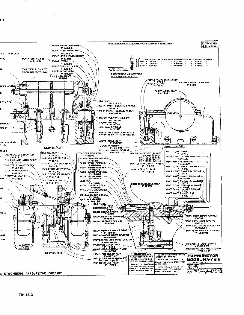
I PUi4? STItvr ' CKIN{I
I e - z r z z zI PUMP srEr BU3HIN6.-I F-Zrrz lI PUM? STEM PACI(IXGI
J ?-zrza,') PUrar 9YEM ----rr_
I P - 2 r 2 2 6 \I PUMP I3TI ,M L INK PIN .
| ?-ztzz+I PUMP STE 't UNK\L p - z r zoz \FUhPLti l I IOLT..1 \
t - l l e l a \
121
FUMF STEM A33EHt-21t'20
THROTTLE SHAFTPACKING ?-2Ot94
alre:gxl
Itr. r-zr4!r),_-_{
l1!/lT
ar DlscH JET A33E.t.,r. (LtFt)+ P - 2 t 4 1 0
)-E D\scH JET AssEI4 (RlG{t)
t ?-2t461- - ROTTLE VALVE SCREW
X STROMEERC CAIBURETOR COMPANY
wrtr G^tit l i lndlo
r t* l€tlc. atrTrHq wm ?ntrc4 lliK wrrH t-ryE 4|.rut.era4. tJ-tr. " . p_"leoo4 " ., t_[ltt
l ' . a l : - l j ' " ' P - l e @ 4 . ' l - r l A ll-r,ta. gc.-!l. . r F-l€dl r . l-llAt
r. vluw s:er rssam)P-3Oo64 IE VALVE TP - 1 3 5 5 t )
NIEDII. I SEAT ASSEXBLYF-Llal l
FLi lT ASSSMSY?-lal8l4
PUMP Fi3'ION SLET,VE A33EM.P - r a o a t
tut€ F1gr6r AssEM.P - \ 3 2 . ! l
PUT{' VALVE* F-lt?47
!!.!!!!EE9\E_3EArE9.
SPR,IN(DRr3a8
P - 2 , \ 2 4 !5TE}4 IU3XIN6 6ASK?T
? - 6 ? Z l
FOR 9OU3LE DECK PUMP PART'tEFtt TO piawtNq tl-tzla-g!
VALVE SEAT CLIPP-r3A9A
LOCK WASHER.P-6664
FILL HD. MACH. SCREWEcoir LEIR sr€M ASSEM P'3ltl -r:core
vlrvE sEAy GAsKETMIXT, CONT SHAFT
- P-rgo7z ". ii"".""l f ll,.;!.coN sPi,lNG WASHER _ ;i;. i ;;; i z;x,c*
P-taZ9 \ oi F-rrza! /rrHrcr
rECOT{ LRtrGIEN NM| , P-tgo7zIECON SPi,ING WASHII I P-ttz9I l!.cox.grrlt gPRrxoI I P-ltoa.lI lECOft. gTflt lrvAatrr
r.ilxT CONTROL SHAFT assf.ltP - t " 4 Z O
MIIT CONT. 3TOFF - l 1 4 r !
iuT. cort sroP PDI? - z \ 2 6 ' l
nttT. cotat. SHAF\ wASHliP- \7416
nrrt COxY SHAFT BUSNIXCP- r74ra
itxr. cotfl SHAFT PACKlttot - r a ! o t
filtY. coxY. PAcKrNqP-13679
ITIXT CONT. SPR\NC Wp- 26 A( |Ii lX?.CONr SHAFT 3t
. - t ]90?lllrl. CO|ff. SHAFT PrN
Ecox. STllt waalrlt - \ \r - \ ! o c r \ \ \ / E C O l t L E 8 0 L E v A L v E
acoI. 3r!t i ItACx',*o =\\\ / '
P-r76os
ECOll. srlM NrtlP- t90c7
WA9HEt,p_,"oro _ . \\\ fco'r.coxlllll$r
flrrcoN. LEvlR As.."
\ 4,
,,n \STEM AssEMWJfirlUS*t-Ur
\\\ \\\\\ \HEAOLE3s SET SCREW\ \ \ \ \ \ t \ \ \ \
b.r ^,1-8ll?o \\ \\\ \\ \/ | eetel \ \ \ ' , ,r ' i \ , \ \ ,)^roLE TUAE \\ t \\
r P-!ftl! \\ :-JlccolrxrrB:tll3)'- \WECON. I!!'lLlqtno \!1!
ECOT{.I{IEDLE?-14722
ECOI{. XEEOLI' IOCK lluT -P-.l8al
ECO{ NIEDLE VAVE ITAA* P- lEOl l
tcox.v^lvl atarP-r1905
MfTEEINO .JIT(MAIN)Auxr P- lO. l 55
HCYil INO JET (ECON)-=-* P- lOrL55
HIA9LE63 'CEEW PLIJO.-P-l+974
]VIAIN AIP gLEED AEAF - 1 6 3 4 7
BLETD AEM (iA3K]T- P-t4',25 /
ilrlllrc J3T tllra
coxr. sHAtr cAtKEtP-r?421
COIT VALYE SPRINGP-tt4 | 6
coilT vALvE PLAIe (Oulfl)P-20393
COHT V[\'E PLA1E RINqP- tae7e
L\.ro
!lra
METEe|NG JET (nx)- r F.to.{,ssiNETERING .JET PLUG- P-)479
IOLE ADJ NUT -=-=\
F-19037 \IDLE ADJ. LEVER P\N-\\
F-6245 \IDLE ADJ LEVER A33EM.
P - 9 z ' 9 t \IOLE D\sCH JET PACKINq
P _ \ S O 5 6 \IOLE DISCH,JET (RIqHTl ]_ x P - 2 r 4 6 8
\ |loLc o\s$r .Jrr (!eFr) / /\ , * P - e l 4 7 r / /
P - r 2 4 0 9 \-oc( WA3HER ----\
\P - l a l c 7 \-iROTTLE VALVE--\ \
- : = P - 2 t 2 S 5 \
!o xot lrlcrtY flrs DlAir{W{EN QiTiI{G 'AFS
MAiFE9 T ALWAIS GIVEgrze oR ENGI I :6oDeL
Fig. 1312
?-t1t7a
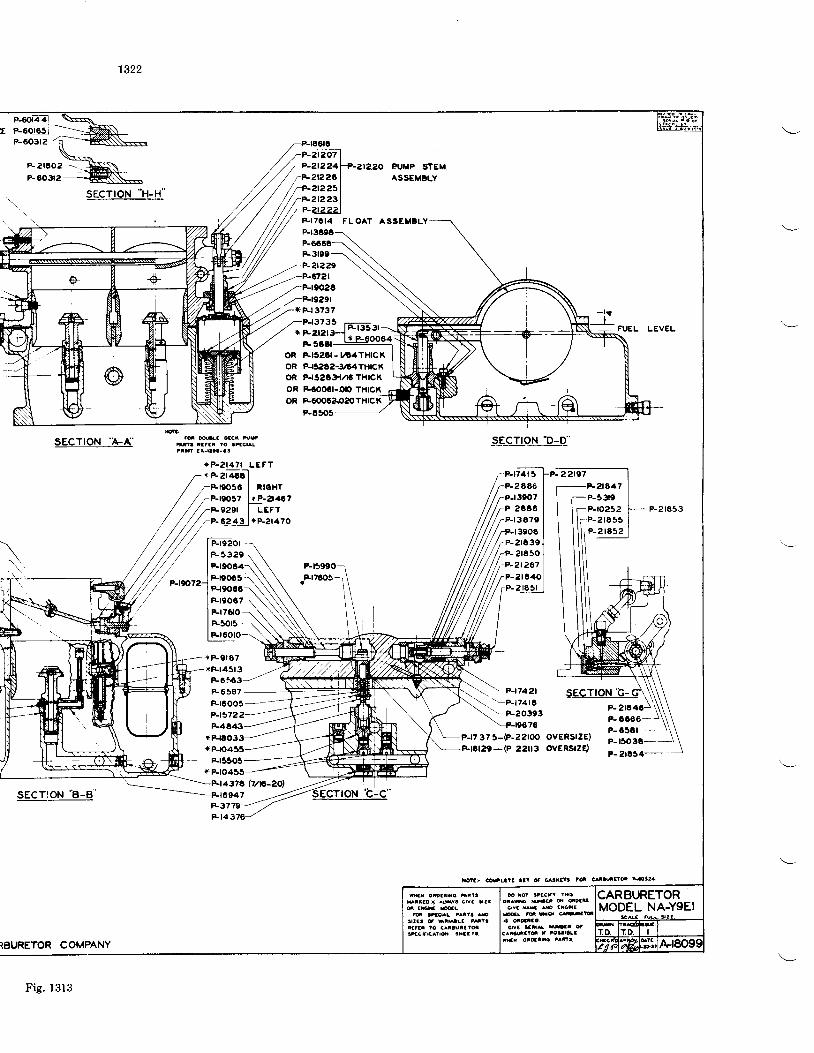
r P-oo!q9l*=--=.--P-60312-6-'o3rz-R -K)\<
\:il'i:-R
F ioY atacfr rxaDa^ff uaat d ootg
crYa Mra do trcit
fs oroairo ir?iua tao* asrs Grv f 9 la
E qcq( r^tl3 ArcsECt c $ar-r3 mlaafaaa lo t^aaut3tdqcsE^t ro i l xaa ta
1322
sEcrroN "H-H"
P-3r09-P-?t229
z-P-19291x Ft373?
P-r3735X F
F3tCl
as ma otci tu,Ma raaar 10 arccrarlaf ! r- [ t l -ar.
sEcTroN "D-D"
F-r74t 32 6663oo7
P 26463 4 7 9
FUEL LEVEL
P-2r653
\
/ //S*ezet/ ,/ ,/ ,/ rP-6243
/ ///// / / / / lP-re2ol
/ / / / / lP-532e-/ // / lFreo64_'/// "-,*'zj li$:_
///// r"-t3eo6//// /rP-2ta3e/// / /rP-2t65o/// ///-P-2t267'////r'^-i',2:
+ P-9rA7+rFl45l3
F65C386587
F_t6OO5-P-I5
--P-t7421'!P-t74t6
-F203937a
P-r7 37 5-(P-22rOOovERsrzE)ovERsrzE)*
t7a (7/lp'-2o,)947
F3779F t 4 3
TEURETOR COMPANY
rP-212Q7 |7 P-2t224ft-aa2o PVMP STEM.*zta?c I AssEMBLy
r r?-212251/7P-2t2231',aP-422?)
F. I7CI4 FLOAT ASSEMELY
OR FLlszAl-rt4Tl{cKoR P-.r5262-3 4THrcXoR P-rszt't/rG THTCKoR Fcooct-o(, THtcf(
[ -F21647i I P-33te
I l i -P-ro252I I l r P -21655
P-CC66-P- 65Ct -
P-t5O36--\
sec!_9!_.4_€'
Fig. 1313
l6tar trLtl3 l:t s atieE ld c^aur{ s5?4.
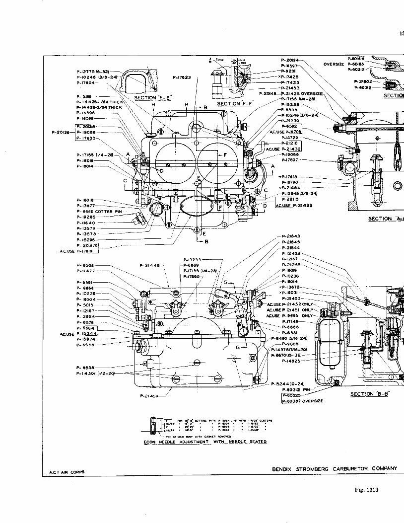
r:
P-t2775 (6-32)
P-toz4g (3/S-2P- 17604 -
P- 5319-P- t 4425- t /C4
F 1442C-:l/C4THrCl(P- 1659AP- 16596
P- t90t6P- t7
P-
P- t367P- 6666 COTTER PINP - 1 9 2 8 5 -
secroN "e-e'
w SECTION F.F
P-t7A23___i,,.!}l\
ovERsrzE F".;*X--*P{7425 \ \-:j:i7.iz
\ :#:-R\ \P-t7423 \ \
F
P-2r453 \ \ F
?-2t4zsovERsrzE\\ \P- r7 t55( !4 -2r ) \ \
' \
P-l-5-2_3_!--- \ \ \F6506 \ \ \
P-2ot48,JP-2t425 ovERsrz\\ \ sEcTto--p-t7t 'stw-zct \ \
' \
/ / aP-2t23O/ / *csEa,/xc.uszets_la
P-ro248(Vr-
P-t47?9
=-P-zt2 to IAC,USE P-zt4321
A
P-r8790*P-zi454
-P-to246\3/C-?4)
-P-2t443
-P-r906CP-t7@7
vP-l9O3l-- - --
r tP-17613- - -_
SECTION '4./
P - i l 6 4 0P- t3579
P_ E5O6 -_\
P - i l 4 ? ? - . \
P- 1357
P- 15295
P- 65t1
P- r50cP - t 4 S O l
P - 2 1 4 4 6 1
P-21
P-t3733
P-t7t55 [/4-2A)P-r?c90
P-2t450-.ACUSE F21452 oNLY-\ACUSEP 2145r ONL
ACUSE FI9C95 ONLY=-
P-17t40-_-\.\P-6660. \P-6361
AC.t SE
(t/2-
P-t460 (3/16-24)-P-9006
P-t437Q(V\C-?O)
Fcc7000- 32)P- t4E25
Y-P452aat$-24) )P-60312 Pt{-- -
rc2 0a td oY rrtx G *al ilrovco
gec.I-9N-!:9"ovEFSTZE
BENDIX STROMBERG CARBURETOR COMPANY
6 ra ' - ra ' * r tE $ t i. rr1 zf. a{- A'. ,Cr'
t-rrao. Lrn fiti r-rv9-' c3rttala -6 . . . L lY lat"i|g . . tsra/t7'F@a r . r . ry5
p- zosz6loc.use p-'zc.Lgj
A.C= AtR CORPS
ECON. IELDL€ ADJUSTMENT WITX NEEDLE SEATED
Fig. 13rB
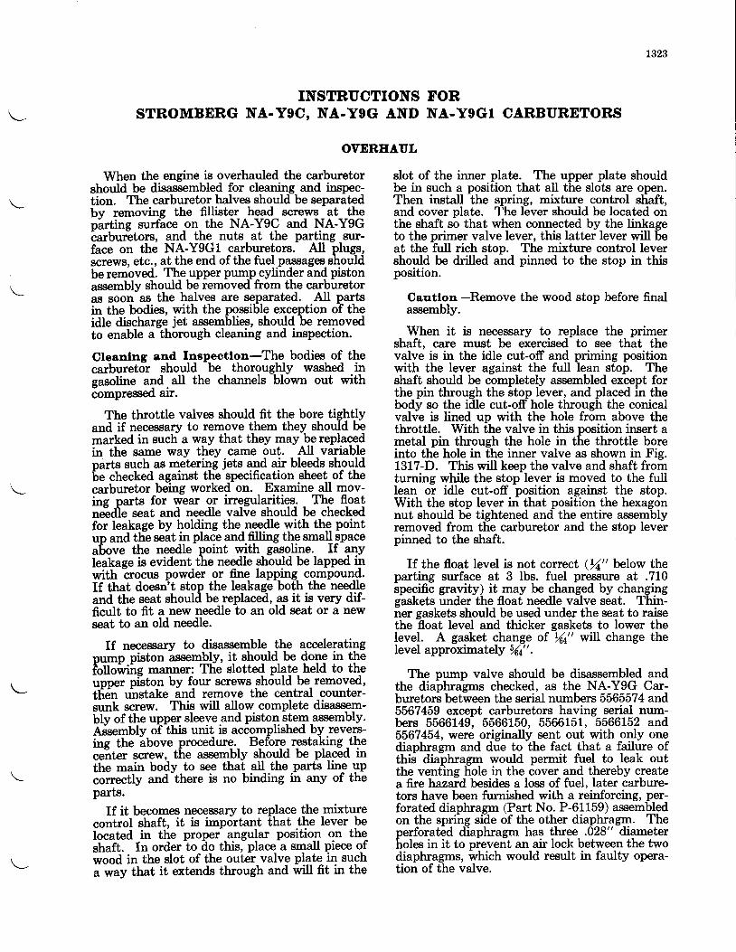
1323
INSTRUCTIONS FORSTROMBDRG NA-YgC, NA-Y9G AND NA-Y9GI CARBURETORS
OVERHAUL
When the engine is overhauled the carburetorshould be disassembled for cleaning and inspec-tion. The carburetor halves should be separatedbv removing the fillister head screws at theoirtine surfice on the NA-Y9C and NA-Y9Gtarbur-etors, and the nuts at the parting sur-face on the NA-Y9Gl carburetors. All plugs,screws, etc., at the end of the fuel passages shouldbe removed. The upper pump cylinder and pistonassembly should be removed from the carburetoras soon as the halves are separated. All partsin the bodies, with the possible exception of theidle discharge jet assemblies, should be removedto enable a thorough cleaning and inspection.
Cleanlng and Inspectlon-The bodies of thecarburetor should be thoroughly washed ingasoline "Td. uU the channels blown out withcompressec arr.
The throttle valves should fit the bore tightlyand if necessary to remove them they should bemarked in such a way that they may be replacedin the same way they came out. All variableparts such as metering jets and air bleeds shouldbe checked against the specification sheet of thecarburetor being worked on. Examine all mov-ins parts for wear or irregularities. The floatnidie seat and needle valve should be checkedfor Ieakage by holding the needle with the pointup and tlie seat in place and fiJling the small spaceabove the needle point with gasoline. If anyleakase is evident the needle should be lapped inwith irocus powder or fine lapping compound.If that doesn-t stop the leakage both the needleand the seat shoulal be replaceil, as it is very dif-ficult to fit a new needle to an old seat or a newseat to an old needle.
If necessary to disassemble the acceleratingDump piston assembly, it should be done in thelo[oi'iire manner: The slotted plate held to theuDDer pfuton by four screws should be removed,tli6n uhstake and remove the central counter-sunk screw. This will allow complete disassem-blv of the upper sleeve and piston stem assembly.Afoembly ollhis unit is accomplished by revers-ine the ibove procedure. Before restaking theceiter screw, the assembly should be placed inthe main body to see that all the parts line upcorrectly and-there is no binding in any of theparts.
If it becomes necessary to replace the mixturecontrol shaft, it is important that the lever beIocated in the proper angular position on theshaft. In order to do this, place a small piece ofwood in the slot of the outel valve plate in sucha o'uy that it extends through and will fit in the
slot of the inner plate. The upper plate shouldbe in such a position that all the slots are open.Then install the spring, mixture control shaft,and cover plate. l'he lever should be located onthe shaft so that when connected by the linkageto the primer valve lever, this latter lever will beat the full rich stop. The mixture control levershould be drilled and pinned to the stop in thisposition.
Cautlon -Remove the wood stop before finalassembly.
When it is necessary to replace the primershaft, care must be exercised to see that thevalve is in the idle cut-off and priming positionwith the lever against the full lean stop. Theshaft should be completely assembled except forthe pin through the stop lever, and placed in thebody so the idle cut-off hole through the conicalvalve is lined up with the hole from above thethrottle. With the valve in this position insert ametal pin through the hole in the throttle boreinto the hole in the inner valve as shown in Fig.1317-D. This will keep the valve and shaft fromturning while the stop lever is moved to the fulllean or idle cut'off position against the stop.With the stop lever in that position the hexagonnut should be tightened and the entire assemblyremoved from the carburetor and the stop Ieverpinned to the shaft.
If the float level is not correct (1" below theparting surface at 3 lbs. fuel pressure at .710specific gravity) it may be changed by changinggaskets under the float needle valve seat. Thin-ner gaskets should be used under the seat to raisethe float level and thicker gaskets to lower theIevel. A gasket change of Y64" will change thelevel approximately /6a" .
The pump valve should be disassembled andthe diaphragms checked, as the NA-Y9G Car-buretors between the serial numbers 5565574 and'5567459 except carburetors having serial num-bers 5566149, 5566150, 5566151, 5566152 and5567454, were originally sent out with only onediaphragm and due to the fact that a failure ofthis diaphragm would permit fuel to leak outthe venting hole in the cover and thereby createafirehazard besides a loss offuel, later carbure-tors have been furnished with a reinforcing, per-forated diaphragm (Part No. P-61159) assembledon the sprihg side of the other diaphragm. Thenerforated diaphrasm has three .028" diameterholes in it to pieverit an air loch between the twodiaphragms, which would result in faulty opera-tion of the valve.
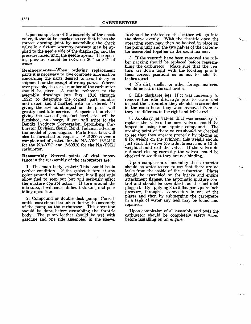
1324CARBURETORS
Upon completion of the assembly of the checkvalve. it should be checked to see that it has thecoruect opening joint by assembling the checkvalve in a fixture whereby pressure may be ap-plied to the needle side of ih-e diaphragm and thepressure raised until the needle opens. The open-ing pressure should be between 20" to 35i' ofwater.
Replacernents-When ordering replacementparts it is necessary to give complete informationconcerning the parts desired to avoid delay inshipment, or the receipt of wrong pafts. Where-ever possible, the serial number of the carburetorshould be given. A careful reference to theassembly drawings (see Figs. 1318 through1322) to determine the correct part numberand name, and if marked with an asterisk (*)giving the size as stamped on the piece, willgreatly facilitate service. A specification sheetgiving the sizes of jets, fuel level, etc., will befurnished, no charge, if you will write to theBendix Products Corporation, Stromberg Car-buretor Division, South Bend, Indiana, advisingthe model of your engine. Parts Price lists willalso be furnished on request. P-2I200 covers acomplete set of gaskets for the NA-Y9C, P-22LL0for the NA-Y9G and P-60910 for the NA-YgGlcarburetor.
Reassembly-Several points of vital impor-tance in the reassembly of the carburetors are:
1. The main body gasket: This should be inperfect condition. If the gasket is torn at anypoint around the float chamber, it will not onlyallow fuel to seep out but will seriously effectthe mixture control action. If torn around theidle tube, it will cause difficult starting and pooridling operation.
2. Compound or double deck pump: Consid-erable care should be taken during the assemblyof the pump to the carburetor. This operationshould be done before assembling the throttlebody. The pump leather should be wet withgasoline and one side assembled in the sleeve.
It should be rotated so the leather will go intothe sleeve evenly. With the throttle open theoperating stem may then be hooked in flace onthe pump unit and the two halves of the carbure-tor assembled together in the usual manner.
3. If the venturii have been removed the rub-ber packing should be replaced before reassem-bling the carburetor. Make sure that the ven-turii are down tight with the locating pins intheir correct positions so as not to hold thebodies apart.
4. No dirt, shellac or other foreign materialshould be left in the carburetor.
5. Idle discharge jets: If it was necessary toremove the idle discharge jets to clean andinspect the carburetor they should be assembledin the same holes they were removed from asthey are different in the right and left barrel.
6. Auxiliary jet valves: If it was necessary toreplace the valves the new valves should belapped in, using fine lapping compound. Theopening point of these valves should be checkedto see that they operate properly by placing an8 lb. weight on the sylphon; this weight shouldjust start the valve towards its seat and a 12 lb.weight should seat the valve. If the valves donot start closing correctly the valves should bechecked to see that they are not binding.
Upon completion of assembly the carburetorshould be water tested to see that there are noIeaks from the inside of the carburetor. Platesshould be assembled on the intake and engineattachment flanges, the automatic mixture con-trol unit should be assembled and the fuel inletplugged. By applying 3 to 5lbs. per square inchpressrure, through a connection in one of theplates and then by submerging the carburetorin a tank of water any leak may be found andrepaired.
Upon completion of all assembly and tests thecarburetor should be completely safety wiredbefore installing on an engine.
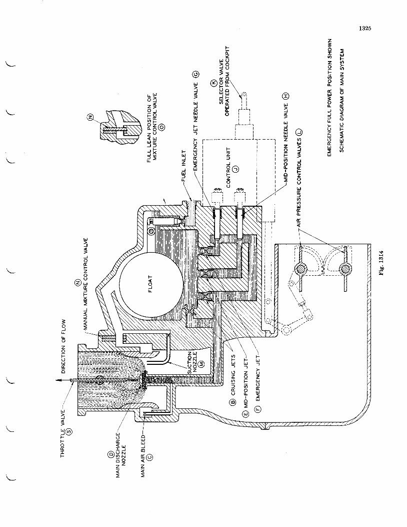
1325
z396 H6 8t z
P $s b3oL o - Tj 3? oU Fz <U ;t r IlrJ U
rrf
d
u0
- f - t -
r il l
i ll l
l it ir l
i li l' l
1,,..1i l-,' i
i lt . ir!-,
lrJ>J
sJod.Fz
a UG ) u- e .
fFx
J
)z
Eo-
lr,l (J
> oi o
rer E 9rV t r L \
! ) o \5 " \i:r'6 t i i
l r j i io- f --- ' lo i i
t l
T t - - - ]l lt l
---- ---l-----1-- - --.
otrJ
lsUJJoUJtrlzt--trJ-)
uzlrJotrIt
LrJ
@lrJ
lslrlJolrJlrJzzIF
r. lrJ
6 lz *O- rE Oa r8 5 0z n< trJr J dJ : )
r l Fj = 5L Z
,t)|!
o6lrJ
lsJotrF.zoUlrj(rftnolrjG(l.
6
tzl
J
P Ot-zou
3IIr|!
zIFulrJgo
od n< vz
hJ(,trf s
/ A U N\7f, N
^ oz z
ILrJ
Js3@F
rotIF
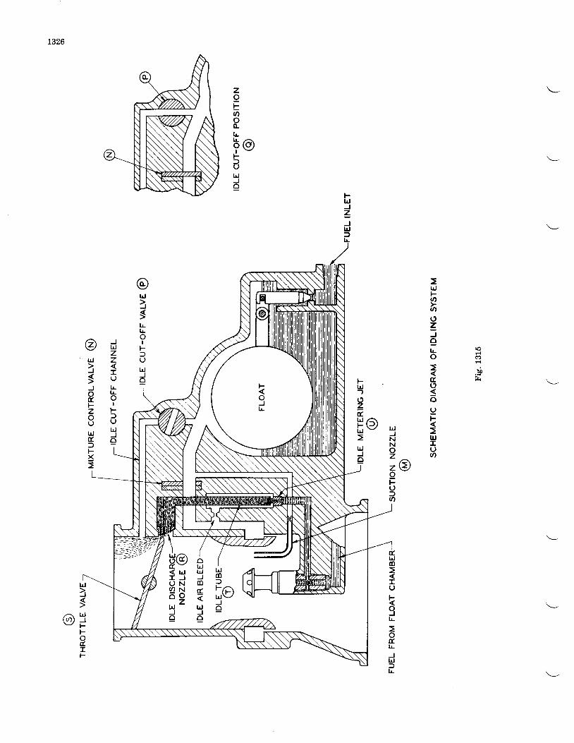
t326
zoboo(L
FIJJzJUJf
L' 9@FfulrjJQ
ro
bo
trJF,nolJ
zJ
eLo
tro
o9F
UJIutn
FLrJ)(,zt
HolrlJe
@lrj
lsLl!oI
F.fuIJJeI
lrJJNNoz= OoFu)o
t.tdo
IoF
9L
otru_JlrJ:)t!
JUJzzIoLt!oI
Fl(JUJJe
@lrJ
lgJotlFzo(J
lrJtrf,FX
oUJlrJJot_
hJJo
r , t - a f l
r_< l^tI JU N( / ) No ozl!Jo
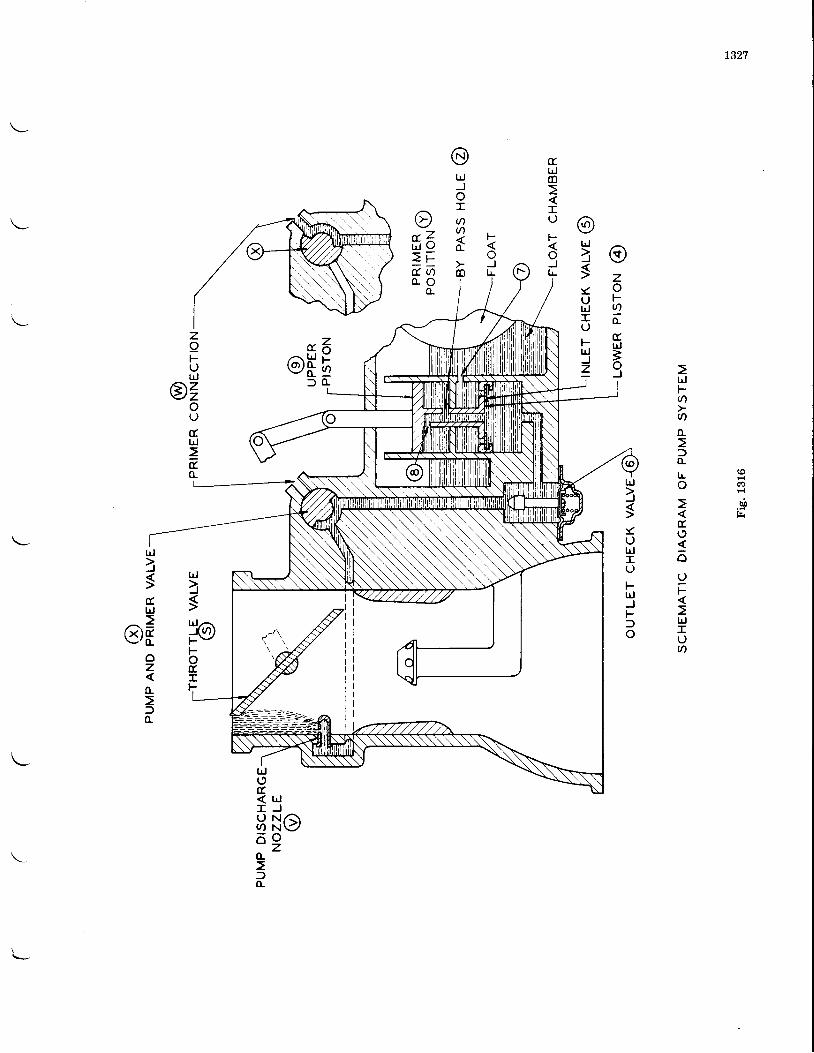
t327
ozoFUIotrlrJ=oJ
@lrJ
l
UbJIuFLrlJz
xbJ(n
Io
@bJJoIqU)
o-
o
6 Zt l O
= E( u )0 - o
@fE:) o-
zoFOlrJ
/^zY)z
i
hD
bJt-v)
oofTL
Iro
t(,
ouF
lrJIoq
lrl>J
ul,.rjIO
FLrJJ1-:)o
outIJ
t
lrJ
l>{lrJa_[ (/) )F -FoEIF
lrJ
lstlrj
g)roz
trl0-
UJuE.< u JI J
8 N O6 2(L
f(L
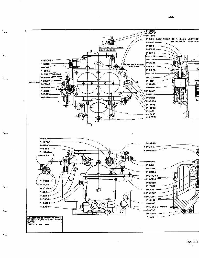
1329
P-t7CO4
P-53f9 - l/32- THICK OR P-14423oR P-t4426
164"THrcl3/64"7i11C1
aRACrMi EOSS.Ftoot4-
(e-ant-I
l?-2t224lP-2t22C
)r-r,rr"IlP-2t22t-l!"21222e-?l229-P- 672r -P-t9020P-|e035.
* P-r3737 -
\ P-r373s-\ \P-20165
G
P-60089P-t02t!tP-60627P-20rc!t
F
P-201c5P-
P- 20i'99
P.
r sTEx AssarP-2t220
(*aza+"-z,a,e-{ P-203o4
lP-2or47LFrgosoP-2t2lO
r6590to596
?-r477r529550731
P-ro248* P-20157
* P-t2422
P-0600'P-C581
P-20roo
P-20rc5P-zt828 *
Ftoo89P-7334F-20167
a?-2t257* ?-212t6
P-84eO
---+-6550
P-ZO1O4
8508
P-I368O STRAINER
Fteoz]gFr905il
Freo52Ft9055
F20306
Ps3r9CAPBIPETO?.S PPIOP TO j'€ENL
Fig. 1318
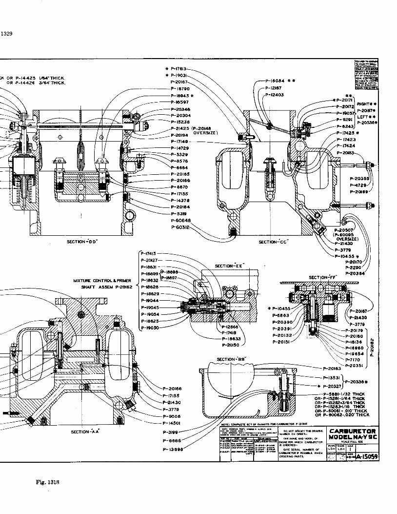
1329
x oR P-14425 L!4 'TH|CK.oR P-t4426 3/64'TlilCK.
MIXTURE @I{TROL A PRN/ER
SHAFT ASSEM P.2O62
SECTION-AA
(P-20r48ovERstzE )
P-t7115
-t7425 *
P- 17423
(P-600e5ovERSTZE)-2r4:10
F3779P-10455 *
P-20t27
P-rEO3l SECTION-EE
sEcTroN-cc
It P-1O455
P-6863
F203oO
?-2290/P-20364P-tc099
P-t06,:t2P-t8020
P-tECz9
P-t9044
P-19045
P-t9054
SECTION-FF
F20301
P-20t32P.20t5l
p-rsssr')>P-2030*
e-zoszt)20roor7r55 2 THTCK
oR-P-1526t-r/O4 THrcroR- P-t52ta€/64 TI{CXoR-P-l5AtiIt/rO TIICXoR- P-6006t - .oto'THtcKOR P- 60062:.O20-THlCl(
P-2r430
--__p_t45ol
P-3t99
P-6006
P-20r05P-201c6
6070
P-t7t55
crn3gl=to"MOOELT{A.Y9C
ry:uq
Fig.1318
P- t3
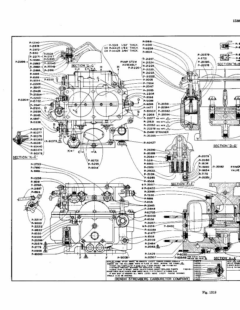
1330
Et8Ct6
P-16019-P-5319 l/3?' THICK.oR P-14425 l/64- THICK.oR P-t4426 3/04'THICK.
PUMP STEMASSEMBLY
P-?t220
P-1o236P-t6014
(e-azot,lP-2t224-
lP-2 t226I P-?r225.
l"-2t223.\P-2t222
F
P.
P-6Ca7 \P-to23t.
P-toz3t-- _F|ltolo -=-\-
P-65CA -1=7-P-19064P-2P.
P-2t42C
P-6550F6506
F20576P-3779P-r0908P-600@
P-r6596 I P-2054FP-r.477 | e-aosea'F60023{ P-20582
,P-z2los lo-aosea
9008P-t7604
20t67P- eol65P- 22rot
P-20577 ser xorr
F-21831 sre rcr:
P-20583 *s rcr:
P-203t9
EP-20391
P-t50ti( F 20t57**t242
F
F-733t
K+J C
zoze-)20rto Irerse Ir6e60 )re654 |7t7o I2o33t)
P-P-
jr-20182
!&2al0! $t mtr
.P-20579:..
.P-6721
ffi:::ffix
SECTION "H-H
:iec!-oN-.o-o"
PRIMEI
VALVE
ooccm ug rre Fo!!ffi mn I pL^cE or lrc$ lEARts ru crrsor.A*cocrr nrtriJt:rc ei Ftd 9m P-2o69 ?&rul ^rD F.a ivtF-CO?St.l IHEIOEO lu$res Fm i€oLlrd FLIKp-w[ rurP I Pitrl ilct v{v: a |&il ssiEt iE[Ac€3 m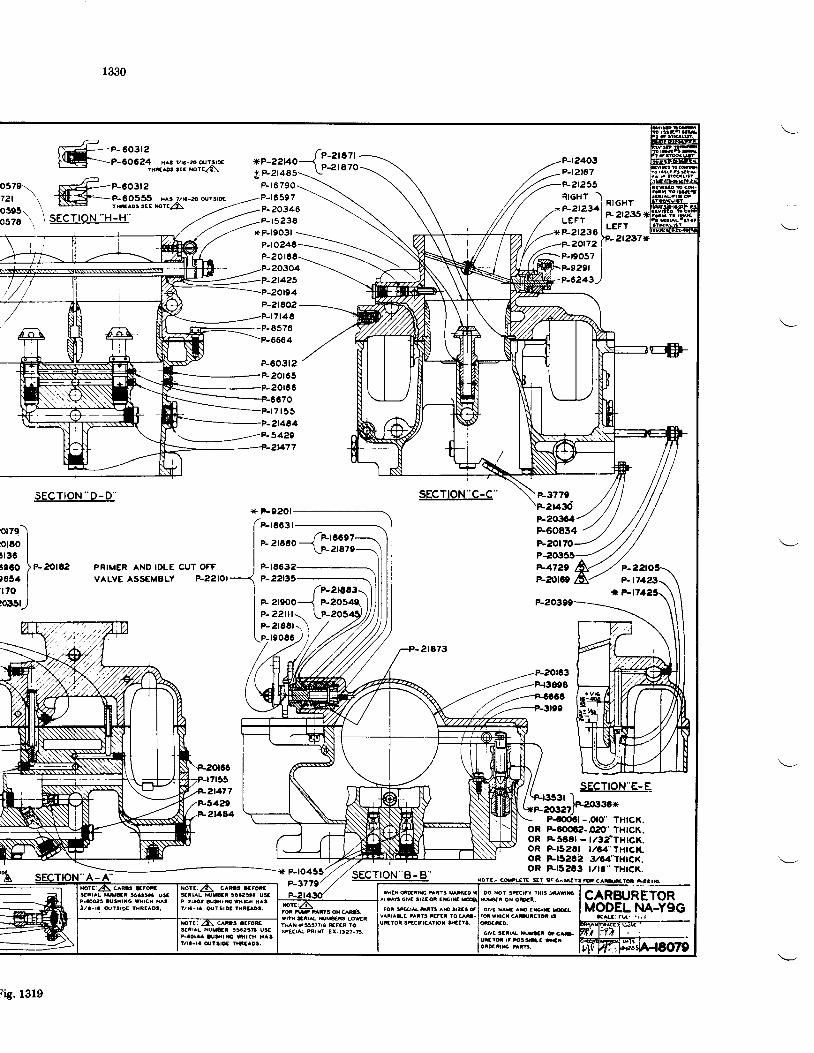
1330
sEcTloN "o-D"
,ffi::::::'ilb:Hi:,?a-
P-603t2F20r65
20rec70
7 r 5 5
. P_3420
sEcTroN-c-c' P-377e1430
I-
t
orze-)prEo Iruac Ite6o )P-2O|C2)654 |' r7o
Ilo35u
PRIMER AND IDLE CUT OFF
vALvE ASSEMELY P-zzl0l
"-r'..0{IX?lF t 6 0
P-22t35
P-203C4F60834F20t70
-.oro' THtcK.oR P-606?-O20'THICK.oR ESECI - t/3tTHt€,K.oR FfszCt t/64' I;ltcr�t.oR Frsar2 3/64-THtcx.oR F-t52t3 t/tt' THtct(.
CARzuRETORMODEL NA-YgG
*{ t : ru! \ r . t
F 21900P- 22i lr \P- 2r88r \ \,itto2l,
P-OO3 lUSXrNO WHrcX hA33/a- ra @?3rE t tsF laD3.
P-zraoa !u$rs ltsrca aagt/ra-! @t5tot lHtw!.
wi€x drR|E uiT! udto *l oo tot sEgtal ttE $nsIL*AG Oil' 3IZ:4 EEIE & N(,sA OI OEN
u U-ans ox qd. | .or sEr[ Nlg ^s 9za3 t I dvi r^s ^xD aErE Erwrn -nrt ruv*c rctrt lvArr^BLt stra ftrEr tocao- lror wrrct caBtcrd 6YSN a555rrra ErF t0spEcrat mtF Ex-t32t-E_ | I oNa $rral x|JEr d g*
uiEld rt tsslraa wx
sEtrAL NUU*I 9$Aar USP-aoraa &$rE nrcN NAg
i is.1319
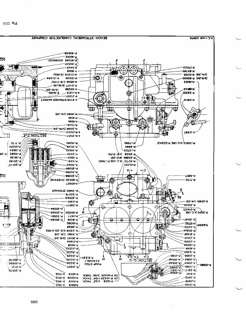
0[8I 'tt.{
9USnOurS xroNS€t
E"ZZZ-{ 3Sn'JV)
'SdU@ UlY.'3'Y
961f9-d Oz'rA)V?s/E)
@z-"n ggtoz-d
zztzta*t9roz ! Jr
( ouraI rseoz-dI rse6r-d
'd1 0969r-d9€t9t-d
o9roz-df6t roz?
99261 069Zt-d69e9-d
e€tel-d90s9-d66€{'Z-drelo9-d9629r-d
Vr-
-d
?-d
-d
lesoz-a) {'z99oz? )ezoogr gfesoz-d I uara')
tggoz-d, 9699lid t
(3d ld
|€e-Otrn(619rr-d 3sn'r 'v)
'F
6r€9-da-d
rd
u3Ntvuts ostrz
t89OZ-dl€9lzrd
LLgo,Z-d
1999-do1|l.1
\--^-=--6ZZtZ:d
9go6r-d d -
96991-d. . : - .2
i8l.so?-d \'96902-d /
, , tz tg 'd/'61902-d
o3U-€ (OZ-Zlt) gO|eZ rd-
oz- r/l) 99tozvz-e/d 1groz-d
togl'|-d9006
'o3u-eD3U-Eo3U-e'o38-e
ozztz'dAr€n3ssvn3ls dnnd
v3rHl ..t92€ gzttl-d uo'v)tHL ..rg/t gettl-d uotto9r-d9ezor?6rogr-d9t99r-d
(o3u-z) 90zl?gttz-d 60toza
(3drd-9/t) gogat(8r-9f/6) Llrtz-d
,291?lZ-d*
I88I
'y)tHL -ze/l 6re9-d
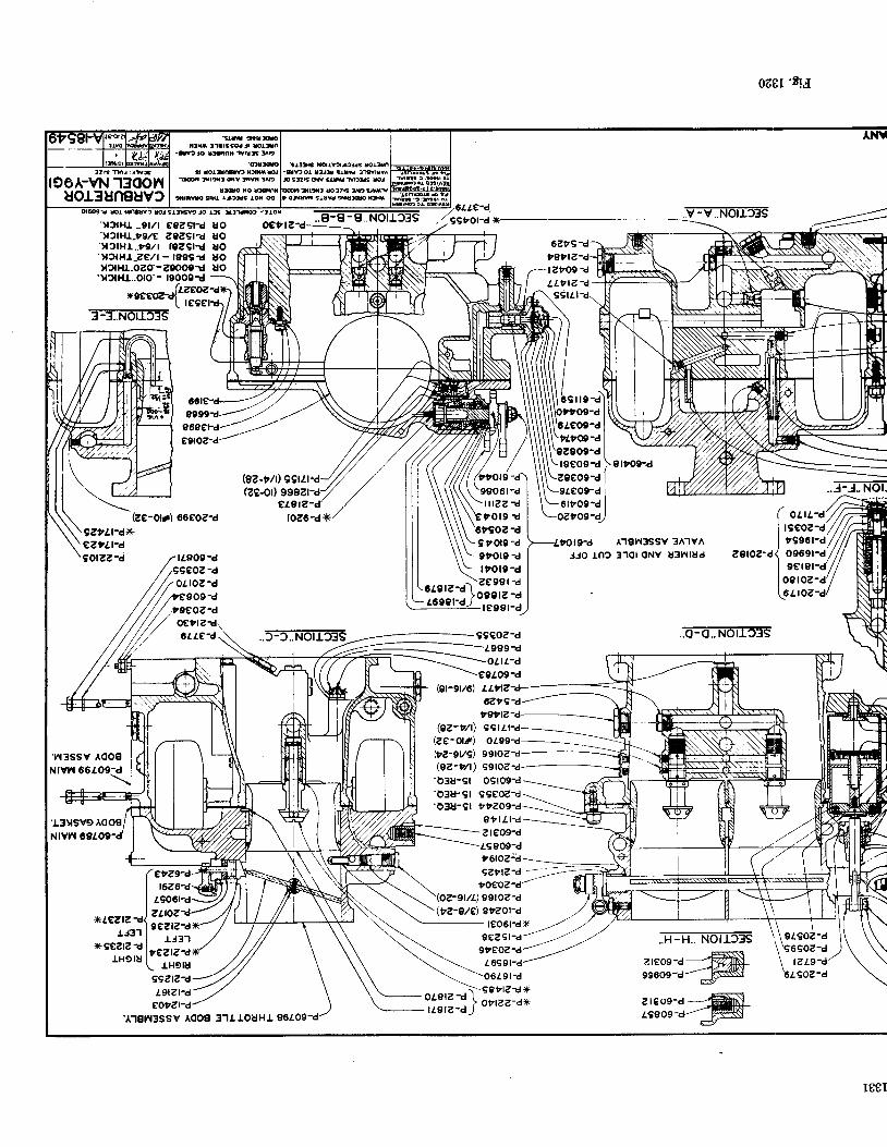
0z8r'Eu
..9-€ -€.. Norr)3s v:ffilrTis'Y?lHl ..91ll egzglrd'y?tHL-?g/e
zezst-d'yttHI..t9./t f9zgtt'yftHl'zelt - t999txzrHL_ozo-29000{'v?tHl..oo'-
3-3..NOrrt3S
oetl
(82-rlr) 99rZr.d(ze-or) 99821
el9l10z6ti(
U OUOUOuouo
---
6Zt9vertz
-lztog -d
LL t t z ' d
egoz-a/
(ze-or) 66soz-d
9906t -d
tnzz-dt o 1 9 d
99111
6t"o9-d
4totg-d A.l€n3ssv3A'lvA9ZrU-A)kez'lt-d90tzz-e
'w suaox3{i t ltsaqJr unn
-fv?f trini xrris fD
i totttcD t)lrr@lU ilr{t dY iln !a9
!!oo io lhxittw sru lJl2r3 toN @
-cD ol tlg araB f,tvrlvFS3ZEdVg&l r f f U
ltil, rcltB !D witola6 s1!wruruw
f z r l m r : t t r
106A-Vtl'I3OOnuot3unguv)
. .J-J-NOl.
Irotg -dgtot9 dltol9-d
Jro rn? 3101 oNv u3nlud
EfiI?:E-i..5:ffiiEis 99€OZ-d
e9t09-d(9f-9f/6) LLtlz-+-
azt9-dugrlz
. .o-o..Notr?3s
@z-r/t)(ze-ol,f)bz'evg)l9z'r/l)'o3u-91'03u-91'o3u-9r
c9t t r -d
99rOZ-d99toe-d-o9l09-d
9Seoe-d
gttLt-azreog-dls909-d
gz"t?-d -,-_-
,otoz'a'99rOe-d
Qz-e/e) stzot-d
-T:n:re-rrc3s,T:::@
:f::--:=@
I88I
'l'lgn3ssv Aooa 3"lLrouHr
- le06l-dx ,.-'gezg'a/ ---gveoz-a/,--
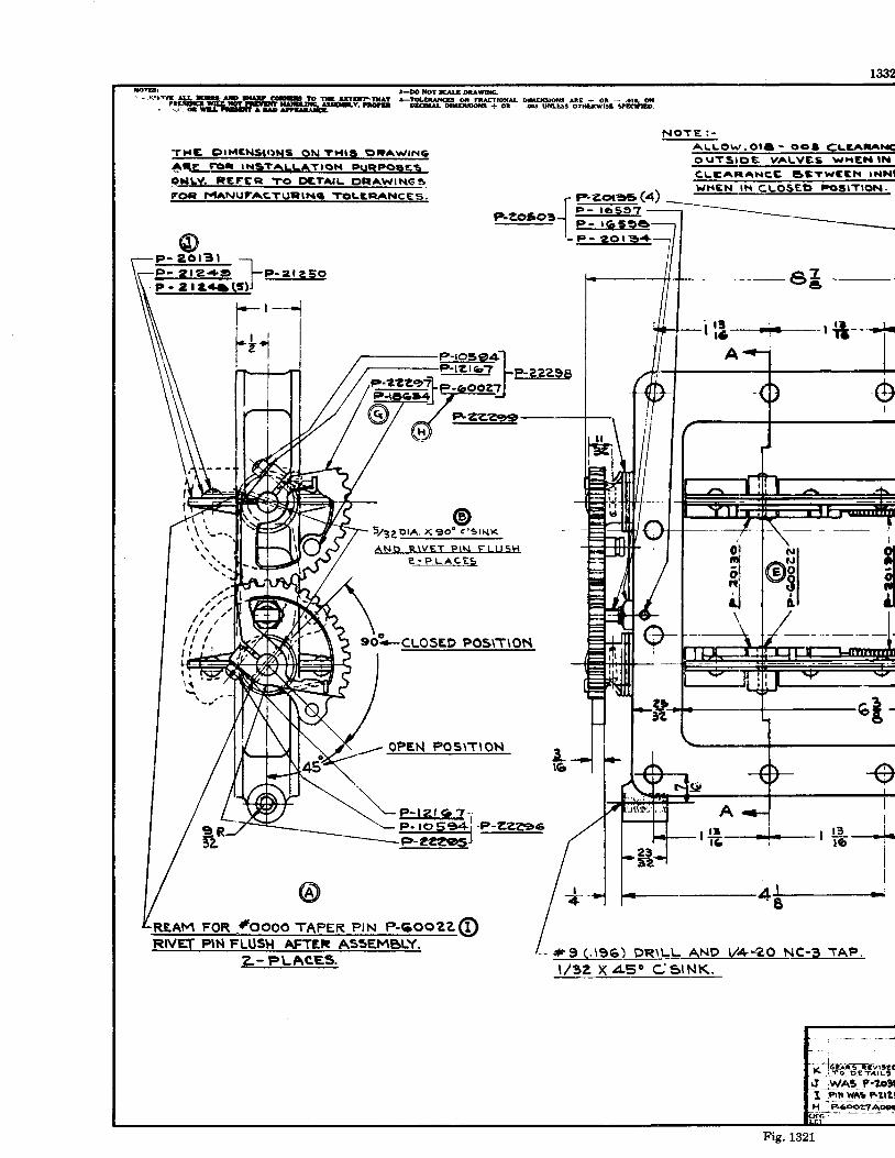
i@! } .{rcIruDure- ""'"F -I*ffo?fr,5$1'oJl* 1l$ti3HrTf"i$E.iriii*#. " ' . i l tUtI lgt^S
THC I) IMENSII 'NS ON ?}I IS gRA\,VINC
^tg_ftrr INstTALtATrOt.. FUOIILY. REEEET TO C)CTAIL DF'AWINGSFG)EI'VIANUFAC,TURINq TC,LCRANCES.
@
N O T E : -
A L L O I . / . O I a - O o l
A, rAFIC,C SETWC
a t r {txDll
t N .N I N
- P - 2 o l 3 l - r-P - 2 t49 . f -P -21e50- - P - 2 | e + a ( 3 ) J
--t
iI
I
Ir-[ *
r lt---------- r if
A
rif--#-3
5 /3eo rA . X 9o ' ; ' s rNK
?-:_P-LA!:E5
s6a-cloa.o "o"tttOn
oPEN POSITION 3i6
'REAM FoR .#oooo TAPER PIN P.6ooZZ@RIVET PIN FLUSH AFTER AssEMBLY.
o
a#
#9 ( . t96) DR\LL ANp y.+-Z.O NC-3 TAP,t , /32 x 45o cstNK.
:- - J _ - - -y ! 6 b R S l E Y l l € CF : f O O - G ? A I L !
!I _tWA5_P.?D3(I iPl!,r vrAr FllzlH iFr6ooeTADEa
e-rosE+-1?gJbl I
IP-cOOZ't l...:,_.--'*t7--
@@f e+zzzse
Fig. 1321
?.- PLACES.
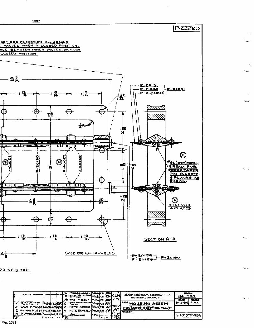
I Ig - OOT C;LEAFIANCE ALL AI IOUNOi vALvEs \^ ,HEr{ rN cLogE() Po6rT l9N.
H q c g E T W C E N T N N E R y A L V e S . O r o - . o 2 6
cLosEo PosrTtoN.
1e-zzzez
J4zGoea)oeruu) SCEAM FOT,
@Ptrr| p-aooc,z,.4PLACES A3sHowN,
-e3
'E -
_TII-st
N
:! ;
I ia .---_-- r !:!," '.. r -1f,
at-- 9/32 DRILL,14-HOLEs
3O_N99_rnp=
Secr roN A-A
fiF����������������==-l- e-zoro,o
P - 2 0 l 3 l -;-izE F.3g,!.P-Z t2+a (3 ) l
- . J - - - -y ! 6 & E 3 l E Y t 3 E O^ ; f O O G T A I L S
I ihn r{Ar F?lzB4g|&35lXJR,rax Ie,-coozzA6xo a't/4<;x lZgI F -
- - - - - J , l " i " , - , * .
a :Muav 'E t l \ ) l
wAs F-zte,94
C iw*€rttryc-
B NOTE ADDEOA NoTE REVlsr,p
Fig. 1321
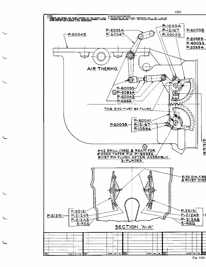
XOtBr TmNoTsruDUWGt-!9!9E A!& ltru m SH[? OOTNEB 7O flE ilTffi THAT baOlffCB ON FMCTTONI DrNroNs ArE + OR - .oro, ON
llllill !!rc w!r. ioT ?Evm H]\lqruNG! lsEruY, rrorE DEm DffircNs +- ot - .@ un$ oTHuwEE SPErts.otuTtotcruI |$EAre [mte
P-60045P- 60034P- 60047
P-60038
P-?O355.-P-qoo_g_a..P-2o354\
AIR THERMO.
T} ' I IS END MUST BE FLUSH
RIVET PIN FLUSH AFTER ASSE,MBLY.
5 /32 D IA .X90& RIVET OVEF
SECTION 'A-A"
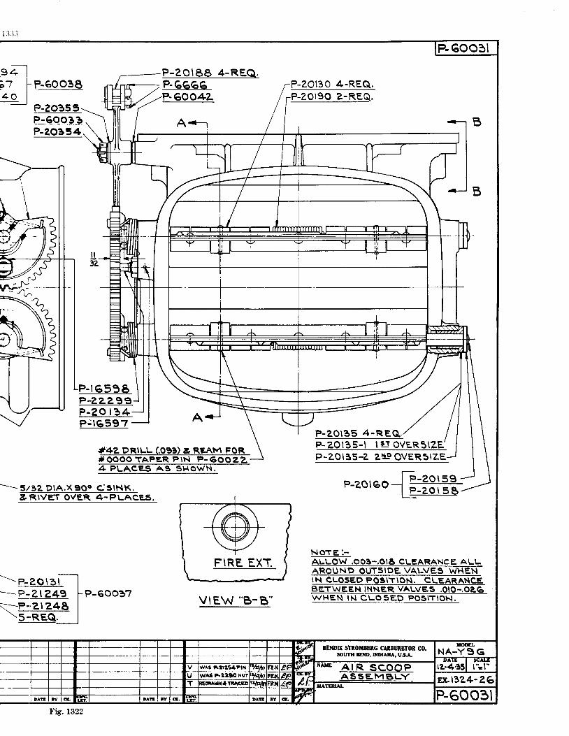
eel;-7 F ReOOgE1 0 1-
?-?o35 5-
P-ZOl8a 4-REQ.P. G6G6P- 60042.
A<-r
P - 1 6 5 9 9P-ZZZAE^P-eo | 3 4-P j l 6 5 9 7
*oooo TAPeR P\N P-6002,2
P-20135 4-REQ. . .P-20135- l | : f ovERs\zEP-ZOr35-2 zNe OVERStZE
P-2O130 4-REQ.P-ZOI90 2-REQ.
P-qeea_sP-20354
-- . . - 5/32 DtA.x900 cslNK,& RIVET OVER. .PLACE,S.
---p-20r3f_l.-'...--p-zr z+g i-p-eoogz\..---P-2,12,48 |\-E BES,_J
I F - z O l 5 9 -b A a \ l F A | : - = : -r -4 \ . , r o " - l
P -zo t 5g -
N O T E : -
POsrr roN. CBET
BENDIX STAOilIENG CAlBlnETOR CO.SOUTH IEIID, IIIDIAIIA Us.A.
Fig. 1322
vtEw "B-8"
1335
INSTRUCTIONS FOR STROMBERG NA.YgE CARBURETORS
OVEREAUL
Disassembly-The carburetor should be dis-assembled for cleaning and inspection eachtime the engine is given an overhaul. After thecarburetor has been removed from the engineand the hot spot and air intake or heater takenoff, the halves gfthe carburetor may be separatedby the removal of the fillister head screws at theparting surface. The economizer needle, pumpSleeve and venturii are held in the tbrottie-bodyas the bodies are separated. The pump sleev-eshould be removed from the operating stemimmediately so there will be no-dangei of itsdropping and-becoming bent. Rubbei packingis used around the venturii so that if it is founilnecessary to remove them, they will have to bedriven out by using a wooden plug as shown inFig. 1323-4. Before removing the throttlevalves, mark them so they may be returned tothe barrels from which they were removed.
Inspectlon and Cleanlng-The bodies andall parts should be thoroughly cleaned in gaso-line and aII passages blown out with compressedair. Parts which should be inspected for wearare the float assembly, float needle and seat,throttle shaft and bushings, economizer needle,seat and operating mechanisms and the pumpstem. All variable parts should be checkedto see that their sizes are in accordance with thecarburetor specification desired.
To disassemble the compound pump unit, itshould be removed from the operating stem andthe four small hexagon head screws which holdthe stem clip in place should be removed. Theconnecting rod between the upper and lower pis-ton is milled flat above the cross hole, so it can beheld with a wrench when removing the centerscrews. Considerable force will be required toIoosen the center screw as it has been staked inplace as a precaution against its coming loose inservice. When the center screw has been re-moved, the upper piston may be lifted out of thesleeve and the connecting rod and lower pistoncan be removed through the bottom of the sleeve.Care should be taken that none of the parts aredamaged during disassembly or assembl! as theyare made to fit with verv close tolerances and asmall nick or dent might iause a binding action.
Replacements-When ordering replacementparts, it is necessary to give complete informa-tion concerning the parts desired to avoid de-lay in shipment or the receipt of wrong parts.Wherever possible, the serial number of the car-buretor should be given. A careful reference tothe assembly drawing (Fig. 132a) to determinethe correct part number and name and, if markedwith an asterisk (*), the size as stamped on
the piece will greatly facilitate service. A speci-fication sheet giving the sizes of jets, fuel level,economizer setting, etc., will be furnished (nocharge) if you will write to the Bendix ProductsDivision, Stromberg Carburetor Division, SouthBend, Indiana, advising the model of yourengine. Parts price lists will also be furnished onrequest. P-60701 covers a complete set ofgaskets for the carburetor.
Reaseembly-All headless screw plugs be-Iow the fuel level should be assembled with shel-Iac, being careful not to get it on the end of theplug where it will come off and be carried by thefuel into one of the metering orifices. Headlessscrew plugs above the fuel level and all otherthreaded parts screwed into the bodies shouldhave a compound of graphite and caster oil puton the threads.
When it is necessary to replace the throttleshaft, the lever which operates the economizershould be assembled in accordance with Fig.1323-8. The throttle valves. when in the closedposition, should fit tightly.
'When the throttle
valves have been fitted, center them in the wideopen position. If the economizer operating leverhas been assembled at the correct angle, thetbrottle valves should be centered. However.when this work is done in the field. it may benecessary to file the stop at A, Fig. 1323-8, orbend it toward the screwed-in stop.
If it is thought necessary to replace a floatneedle or needle seat it is recommended that bothbe replaced at the same time as it is very difficultto fit a new needle to an old seat or a new seat toan old needle. In ordering these parts, be sureto give the size of the by-pass hole in the floatneedle seat. This by-pass hole meters the fuelduring inverted flight and its size has beendetermined to meet the requirement of thatparticular engine and it is, therefore, importantthat a seat having the proper size by-pass holebe used for replacement purposes.
The float level should be r7(', phts 3/a" and,minus Y6a" below the parting surface, when usingfuel of .710 specific gxavity, and is dependentupon the thickness of the gasket under the floatneedle seat. The level should be checked underthe conditions encountered in service as regardsthe fuel used and the fuel pressure or head atthe carburetor. If a fuel pump is used, a pres-sure at the carburetor of 3 lbs. per square inch(117" gasoline at .710 specific gravity) should beused in checking the fuel level. A gasket Ye"thick should be used first and if the level is notcortect, thicker gaskets should be used to lower
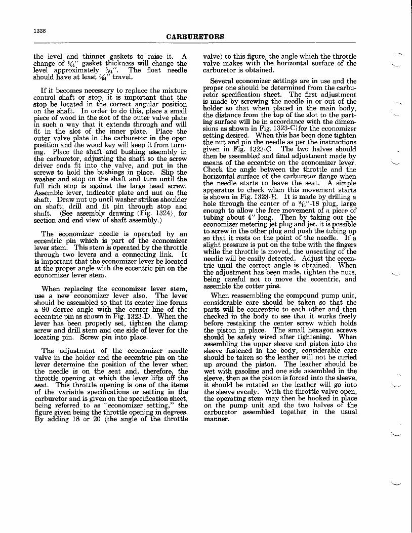
1336CARBURETORS
the level and thinner gaskets to raise it. Achange of |(t" gasket thickness will change theIevel approximately Y64". The float needleshould have at least 9(a" travel.
If it becomes necessary to replace the mixturecontrol shaft or stop, it is important that thestop be located in the correct angular positionon the shaft. In order to do this, place a smallpiece of wood in the slot of the outer valve platein such a way that it extends through and willfit in the slot of the inner plate. Place theouter valve plate in the carburetor in the openposition and the wood key will keep it from turn-ing. Place the shaft and bushing assembly inthe carburetor, adjusting the shaft so the screwdriver ends fit into the valve, and put in thescrews to hold the bushings in place. Slip thewasher and stop on the shaft and turn until thefull rich stop is against the large head screw.Assemble lever, indicator plate and nut on theshaft. Draw nut up until washer strikes shoulderon shaft; drill and fit pin through stop andshaft. (See assembly drawing (Fig. L324), forsection and end view of shaft assembly.)
The economizer needle is operated by aneccentric pin which is part of the economizerlever stem. This stem is operated by the throttlethrough two levers and a connecting link. Itis important that the economizer lever be locatedat the proper angle with the eccentric pin on theeconomizer lever stem.
When replacing the economizer lever stem,use a new economizer lever also. The levershould be assembled so that its center line formsa 90 degree angle with the center line of theeccentric pin as shown in Fig. 1323-D. When thelever has'been properly se*t, tighten the clampscrew and drill stem and one side of lever for theIocating pin. Screw pin into place.
The adjustment of the economizer needlevalve in the holder and the eccentric pin on thelever determine the position of the lever whenthe needle is on the seat and, therefore, thethrottle opening at which the lever lifts off theseat. This throttle opening is one of the itemsof the variable specifications or setting in thecarburetor and is given on the specification sheet,being referred to as "economizer setting," thefigure given being the throttle opening in degrees.By adding L8 or 20 (the angle of the throttle
valve) to this figure, the angle which the throttlevalve makes with the horizontal surface of thecarburetor is obtained.
Several economizer settings are in use and theproper one should be determined from the carbu-retor specification sheet. The first adjustmentis made by screwing the needle in or out of theholder so that when placed in the main body,the distance from the top of the slot to the part-ing surface will be in accorda4ce with the dimen-sions as shown in Fig. 1323-C lfor the economizersetting desired. When this has been done tightenthe nut and pin the needle as per the instructionsgiven in Fig. 1323-C. The two halves shouldthen be assembled and final adjustrnent made bymeansr of the eccentric on the economizer lever.Check the angle between the throttle and thehorizontal surface of the carburetor flange whenthe needle starts to leave the seat. A simpleapparatus to check when this movement startsis shown in Fig. 1323-8. It is made by drilling ahole through the center of a Yt6"-L8 plug, largeenough to allow the free movement of a piece oftubing about 4" long. Then by taking out theeconomizer metering jet plug and jet, it is possibleto screw in the other plug and push the tubing upso that it rests on the point of the needle. If aslight pressure is put on the tube with the fingerswhile the throttle is moved, the unseating of theneedle will be easily detected. Adjust the eccen-tric until the correct angle is obtained. Whenthe adjustment has been made, tighten the nuts,being careful not to move the eccentric, andassemble the cotter pins.
When reassembling the compound pump unit,considerable care should be taken so that theparts wiII be concentric to each other and thenchecked in the body to see that it works freelybefore restaking the center screw which holdsthe piston in place. The small hexagon screwsshould be safety wired after tightening. Whenassembling the upper sleeve and piston into thesleeve fastened in the body, considerable careshould be taken so the leather will not be curledup around the piston. The leather should bewet with gasoline and one side assembled in thesleeve, then as the piston is forced into the sleeve,it should be rotated so the Ieather will go intothe sleeve evenly. With the throttle valve open,the operating stem may then be hooked in placeon the pump unit and the two halves of thecarburetor assembled together in the usualmanner.
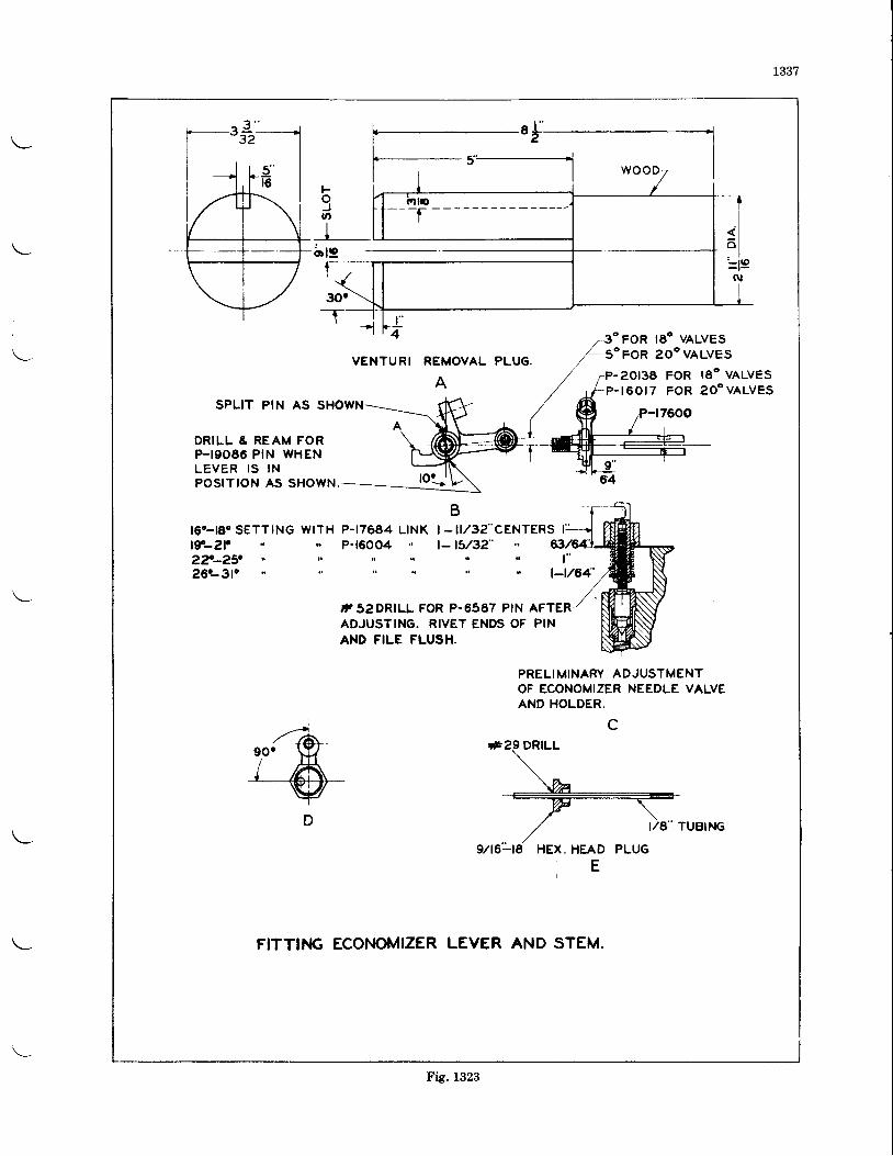
1337
brg
l "4 .-3o FoR lEo vALVEs
L-5"FoR ao"vALVEs
P-2OI3E FOR I8O VALVESP- I60 I7 FOR 20.VALVES
SPLIT PIN AS SHOWN
DRILL & REAM FORP-I9O86 PIN WHENLEVER IS INPOSITION AS SHOWN
t60-t8" SETTING WITH P-17684 LINKr9-2P P-1600427-2?26.-3lo
t "t-t/64'
AFTERPIN
PRELIMINARY ADJUSTMENTOF ECONOMIZER NEEDLE VALVEAND HOLDER.
c#2.9DRILL
E
FITTIT.IG ECONOMIZER LEVER AND STEM.
FoJo
VENTURI REMOVAL
A
| - lt l32"CENTERS r' jt- t5/32"
,T52DR]LL FOR P-6567 PINADJUSTING. RIVET ENDS OFAND FILE FLUSH.
Fig. 1323
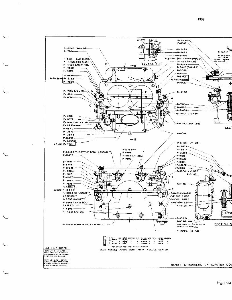
1339
P-fo24a F/A-zelP- t7604
P- 53p t/32P- | 446-t/64rHtcKF- ta42€-il/34TH|CKP- t6 59aP- rc5e6
eo|l€P- t5702
Fr7423P-2r453
P-20t4A -tP-2t423
._ p-t7tss lw-zd
F t 5 7 6 2P- t60DP- laOlzl
P-r00t6--=*\P- t3677-
--.--
P - l
e- sorr ---.-\P - t 2 t 6 7 - \
P-17t35 l /4 -
P- 0660 coTTER P||.1
P - t 8 O O 4 -
*P-t76t3- -
c Fr679O-
JJJ'*z l lsa-
P- t02€5P- i lG 40P- 13379 '
P - t 3 3 7 EP-
6 r r - t ' I t rE r rn r - t ta ! . Lm srx r -v r " caxra t r. d - r f . . Lm. . . t - t vv '. t ' f ' . . i s . . . r t a r t t. * J F r 6 { . ' r - r i / s
-P-r450r Q/2 -20)
r - P- f 7155 l t /4 -261
P-t7t4g
-P-848O lYt6-24)
f-2t2o8 ?-REA.-P-900a 2-REQ
R607000- 3P- t4325
2 lP-00312F-OO64A ^ ̂ {s,c - z. u, t,wrxrros scr mrc I
sEcTroN "8,
-t5224 (to-24J
BENDIX STROMBER6 CAFzuRETOR COI
A.C.USE P- r75r9
P-6O4AE THROTTLE BODY ASSEMBL
, - . ; ' - ] \r - r t 6 r - - - - - \ \ \
P-6666 -- ---\
P - t o 2 3 a - - - - - \
p_ eceal -\-
a6.ggg e-rrgan['--------.-'-----------'...-
P_ 2e21 -P- 6576
P- 15074 STRAINER
E
E
A S S € M B L Y ,P- 8556 GASKETP- '0497 MAIN BODYGASKET.---.------_P_ 6300 -P- t4SOt \ t /2 -2q
P- 60499 MAIN BODV ASSEMBLY
P- 60312 - -
*60a57-
P-r2403\p-reror- ------*arasr ------------:P-tooD ---
\P-ro23B ---------\
A . C . = A I R C O R P S
Fig.1324
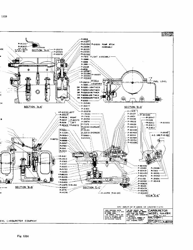
1339
2t2262t225sEcTtoN
"H_H"-P-2o57er P_2O595 23
s
P-2057A
r - - - + F 9 1 8 7
*R.€O3*P-O455-
Fr5503--
.---"-21?29rP-6121
OR F8OOOAO2OTHrcXP-A505
F l 7 6 l 4 F L O A T A S S E M B L Y -
oR Fr3z8t-Lt4TH|CXOR P{eoz-3rt4Txlcxoi F{3aat{reTH|CXoR F{OOO|-OO THtcK
SECTION 'A.A'
SECTION "B-8,
Etr6 CAFzuRETOR COMPANY
sEcTtoN -o-o'
p-rz?3-lP-20t21P-r8 63 |P-16 699P- r 4632P-16626P- r86 2 9F- 60493
T P-6O4s2- P-60541
P-60494P - r 9 0 5 4P- 60405
FU€L LEVEL
P-60500
-*F t45 l3 - - -
F6563/P- 6 587
P-r6005PJa?22P-4643--
!\-"--orJ- P - 1 2 a 6 5
,.,- P-6O4194 P ' O O 4 ? O
/.P.60376zl.,.P-Att59
/ / .P-6644)/.,/ /.P-6O342/-1',-z*6_06?a
= : - - P - 6 0 3 8 1'"':-p-60474
- p-rsoa3 l
A.C. USE P-0il62 |
P- 21646P - 5 6 0P-19055P-r904?
P- et8S4P - 6 0 4 t A
60379
roti @rtYf rat * sia?a ad c^r@idd p-ao?ol
\ ' \ - P - 2 o s 6 3
\-l-2os77. - P-2 t a3 l
P- 60 462
wu otoarc xrttcArioi( sr! crva 9ll
d tRur tattg ^Dsrat! f str-ta mi!ftrca rc catalttM
Fig. 1324
1341
TNSTRUCTIONS FOR BENDIX.STROMBERG NA.YgJ CARBURETORS
OVERIIAUL
I)lsassembly-The carburetor should be dis-assembled for cleaning and inspection at eachengine overhaul and any part worn beyondserviceable use should be replaced. All workshould be performed on a clean bench and careshould be taken to dispose of all lockwires re-moved during disassembly to insure againstany of the small pieces becoming lodged in thecarburetor at reassembly. The entire PressureOperated Economizer and Valve Body should befiftt removed from the rear face of the carbure-tor, by removal of the six Elastic Stop Nuts,and carefully set aside. This unit will be treatedin detail in later paragraphs. The Link Boltsshould now be removed from the Pump Stemand from the upper end of the Link bet',rr,.enMixture Control and the Cruise Valve. Unscrewand remove the two Bolts which are in the AirHorn and accessible from the bottom and allElastic Stop Nuts around the flange which holdthe Throttle Body and Main Body together.The Throttle Body can now be lifted off but caremust be taken to immediately remove the PumpP_iston and Sleeve Assembly from the PumpStem to prevent it dropping off and being dam-asd. The Automatic Mixture Control Unitsf,outd be removed by the use of special Span-ner Wrench, T-24977, and carefully set away.CAUTION: THIS UNIT MUST NOT COMEIN CONTACT WITH MERCURY AS THISELEMENT HAS A VERY DESTRUCTIVEEFFECT ON THE BELLOWS. Disassemblvand service of this unit will be treated in sepa-rate instruction sheets.
To disassemble the compound pump unit thefour small hexagon head screws which hold thestem clip in place should be removed. The con-necting rod between the upper and lower pistonis milled flat above the cross hole so it can beheld with a wrench when removing the centerscrew. Considerable force will be required toloosen the center screw as it has been staked inplace as a precaution against its coming Ioosein service. When the center scr:w has been re-moved the upper piston may be lifted out of thesleeve and the connecting rod and lower pistoncan be removed through the bottom of thesleeve. Care should be taken that none of theparts are damaged during disassembly or as-sembly as they are made to fit with very closetolerances and a small nick or dent might causea binding action.
The rubber packing rings around the venturiiswell, making it necessary to remove the ven-turii by driving with a plug similar to thatshown in Figure L327-A. This packing should bereplaced before reassembly.
Before removing the throttle valves, theyshould be marked to insure their return to thebarrel from which they were taken. Care shouldbe taken not to nick the edges of the valves.
The Main Metering Jets are accessible frornthe bottom of the carburetor and the Econo-mizer Metering Jet from the right side. Afterremoval of the Hex Head Jet Plugs the jets canbe disassembled by the use of Metering JetScrewdriver T-24923. The Cruise Valve Meter-ing Jet is accessible from the bottom of thecarburetor, under the rear float chamber, bythe removal of its Hex Head PIug and the useof the same screwdriver used on the other jets.
In order to remove the Float Needle Seat, thesmall Iock clip must be disassembled and specialsocket screwdriver, T -L9276, must be employed.
Removal of the Diaphragm Pump CheckValve is accomplished by the use of SpecialSocket T-25075.
All other main body parts and plugs may beremoved.Inspeotlon and Cleanlng-The bodies and allparts should be. thoroughly rinsed in gasolineand all passages blown out with compressedair. Following parts should be inspected forwear: Float assembly, float needle and seat,throttle shaft and bushings, mixture control andcruise valve stems, and the pump stem andleather. Check all variable parts (jets, bleeds,etc.) to see that their sizes are in accordancewith the proper carburetor specification.
Replacernents-When ordering replacementparts it is necessary to give complete informationconcerning the parts desired to avoid delay inshipment or the receipt of wrong parts. Where-ever possible the serial number of the carburetorshould be given. A careful reference to thespecification sheet and the assembly drawing(Fig. 1330) to determine the correct part numberand narne. and if marked with an asterisk (*)the size as stamped on the piece and listeilon the specification sheet, will greatly facilitateservice. A specification sheet giving the sizes ofjets, fuel level, economizer setting, etc., will befurnished (no charge) if you will write to theBendix Products Division, Stromberg Carbure-tor Division, South Bend, Indiana, advising themodel of your engine. Parts price lists will alsobe furnished on request. P-61163 covers a com-plete set of gaskets for the NA-Y9J.
Reassernbly-All headless screw plugs belowthe fuel level should be assembled with shellac,being careful not to get it on the end of the plug
1342CARBIIRETORS
where it may come off and be carried by the fuelinto one of the metering orifices. Headlessscrew plugs above the fuel level and aII otherthreaded parts screwed into the bodies shouldhave a compound of graphite and castor oil puton the threads.
When it is necessary to replace the throttleshaft the new style shaft, bearing the samepart number but having a larger diameter(%2't instead of rYn") at the point where thethrottle stops are assembled, is used. It willalso be necessary to use a new throttle stopP-61285, a new washer, P-61288, new pumplever and stop assembly, P-61283 and No.
-0
taper pins instead of the No. 0000 size. Thethrottle stop should be assembled to the throttleshaft in accordance with Figure 1327-Ei. Thethrottle valves should fit tightly when in theclosed position. After the throttle valves havebeen fitted turn them to the wide open position.The wide open throttle lever stop- arni shouldjust touch the screwed-in stop in this position;if not, either fiIe a little off point "A" as shown inFigure L327-B or bend the stop towards thescrewed-in stop. Leaving the valves in the wideopen position with the throttle stop against thescrewed-in stop, assemble the pump lever withits_ stop against the screwed-in stop at the pumpside of the throttle body and clamp securely.The shaft can now be iurned froni the wideopen position and the pump lever drilled, reamedand pinned with a No. 0 taper pin.
If it is thought necessary to replace a floatneedle or needle seat it is recommended thatboth be replaced at the same time as it is verydifficult to fit a new needle to an old seat or anew seat to an old needle. In ordering theseparts be sure to give the size of the by-passhole in the float neldle seat. This bv-pais holemeters the fuel during inverted flighf and itssize has been determined to meet the require-ment of that particular engine and it is, there-fore,, important that a seat having the propersize by-iass hole be used for replicemenl p'ur-poses.
The float level should be rZ" plus V6a" minusW" below the parting surface, when usingfuel of .710 specific gravity, and is dependentupon the thickness of the gasket under the floatneedle seat. The level should be checked underthe conditions encountered in service as regardsthe fuel used and the fuel pressure or head atthe carburetor. If a fuel pump is used, a pressureat the carburetor of 3 lbs. per square inch (L17"gasoline at .710 specific gravity) should be usedin checking the fuel level. A gasket Ye" thickshould be used first and if the level is not cor-rect use thicker gaskets to lower the level andthinner gaskets to raise it. A change of %,"gasket thickness will change the level approxi-mately Y6a". The float needle should have at
least Y6a" travel. A conveniently located fuellevel test hole will be found on the left side ofthe main body just below the parting surfaceand ahead of the needle valve chamber. Bvremoving the /s" pipg plug from the slopin-ghole the fuel level can be observed without dis-assembly of the carburetor or removal from theenglne.
If it becomes necessary to replace the mix-ture control shaft or cover assembly it is quiteimportant that the stop be located in the cor-rect angular position on the shaft. All partsshould first be assembled and grease should beapplied between the Iatch plates to insureagainst their sticking or binding in service.The cover should be turned on the shaft until itrests against the "Automatic Lean" stop. With-out moving the cover rotate the shaft until theslot in the end of the shaft lines up with theupper screw hole as shown in Figure 1327-C. Puton the lever and clamp securely by tightening thenut. Insert the valve plate in its proper loca-tion, put the cover on the carburetor and fastentemporarily with two screws. Rotate the mix-ture control 38' clockwise to the "Manual FullRich" position. Carefully remove the coverand note the valve plate. Both "Manual FulIRich" ports should be open as shown in theuppe{ half of Figure 1326 (52). The cover maynow be pinned to the shaft by drilling a No. 42hole, reaming for a No. 0000 taper pin and insert-ing the pin as shown in Figure t327-L. The innervalve plate screws should not be removed unlessthe plate is being replaced. The new plate shouldbe assembled with shellac as a seal againstleakage and finally lapped with fine grindingcompound.
If the Cruise Valve and Primer stem showssigns of excessive wear it should be replaced.The new stem, bushing, packing, washer andlever may be assembled as a unit and insertedinto the cover later. The slots in the end of thestem should be set at an angle of 30" to thelever and the lever clamped tieht. Check thor-oughly with Figure .1327-D,to Jee that the assem-bly is correct before drilling and pinning, as cor-rect functioning of the carburetor depends con-side_rably on the exactness of the- assemblyangles.
When reassembling the compound pump unitconsiderable care shoda be tiken so ttrit theparts wiII be concentric to each other and thenchecked in the body to see that it works freelybefore restaking the center screw which holdithe prfton in place. The small hexagon screwsshould be safety wired after tightening. Whenassembling the upper sleeve and piston into thelower sleeve fastened in the body, be carefulthat the leather is not curled back around thepiston. The leather should be first wet withgasoline and one side assembled in the sleeve,
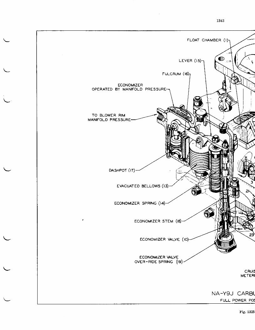
1343
FLOAT CHAMBER ( t )
L E V E R ( I
FULCRUM (
ECONOMIZEROPERATED BY MANIFOLD PRESSURE.
TO BLOWER RIMMANIFOLD PRESSURE
DASHPOT (t7)
EVACUATED BELLOWS (r3)
ECONOMIZER SPRTNG (r4)
ECONOMTZER STEM (r8)
ECONOMTZER VALVE (
ECONOMIZER VALVEovER-RrDE SPRTNG 0g)
4 '
c
CRUISMETERI
NA-YgJ CARBLFULL POWER PO:
Fig. 1325
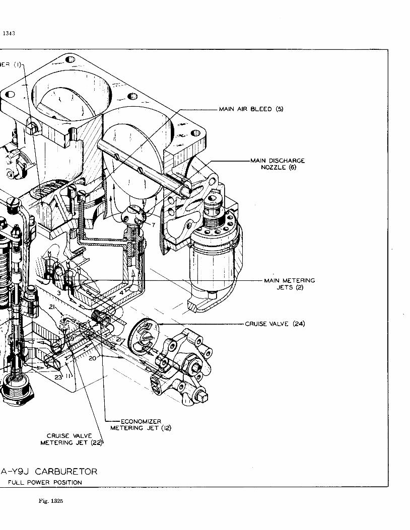
l 3 {3
CRUISE VALVEMETERING JET
A_YgJ CARBURETORFULL POWER POSITION
MAIN AIR BLEEO (5)
MAIN DISCHARGENozzLE (6)
MAIN METERINGJErS (2)
cRUrsE vALvE (24)
ECONOMIZER
Fig. 1325
METERTNG JET (l2)
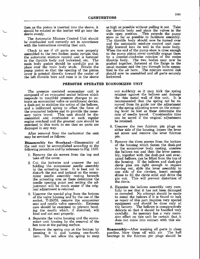
1345CARBIIRETORS
then as the piston is inserted into the sleeve, itshould be rotated so the leather will go into thesleeve evenly.
The Automatic Mixture Control Unit shouldbe overhauled and correctly set in accordancewith the instructions covering that unit.
Check to see if aII parts are now properlyassembled to the two bodies; make certain thatthe automatic mixture control unit is fastenedto the throttle body and lockwired, etc. Themain body gasket should be carefully put inplace over the main body studs. Rotate theb*p piston so. that the opening of the pistoniovei is pointed directly toward the center ofthe left throttle bore and raise it in the sleeve
The pressure operated economizer unit iscomposed of an evacuated sealed bellows whichreep6nds to manifold pressure changes to ac-tuale an economizer valve or enrichment device,a dash-pot to stabilize the action of the bellows,and a balibrated spring to offset the force ofthe evacuated bellows and to provide the neces-sarv valve travel. This unit should be dis-ass6mbled and overhauled at each regularengine overhaul and the greatest care should beexCrcised irr this work to see that no parts aredamaged in any way.
After removal from the carburetor the unitmay be serviced as follows:
Dlsaseernbly for Overhaul-Disassembly ofthe unit may be accomplished according to thefollowing procedure and by reference to Fig, i1332:
1. Remove the six screws from the top andtake off the cover.
2. Cut the lockwire and unscrew the nutholding the economizer needle assemblyto the actuating lever. It is best not todisturb the nut and locknut on the econo-mizer needle assembly resting beneaththe actuating arm as these determine theneedle opening point and setting the ad-justment wiII be much easier if the orig-inal adjustment is retained.
3. Unscrew the special plug from the bottomof the valve housing and by the use of thesocket, T-25076, remove the economizerseat and needle valve assembly. Extremecare should be exercised to prevent bend-ing the needle which, if distorted, willbind and not seat properly.
4. Separate the valve housing and the econo-mizer unit housing by the removal of thehex nuts at the parting surface.
5. Remove the spring cup at the bottom bypressing it in and turning one-fourthturn. Do not allow the spring to snap
as high as possible without pulling it out. Takethe throttle body and place the valves in thewide open position. This extends the pumpstem as far as possible to facilitate assembly.The throttle body should now be turned overand the automatic mixture control unit care-fully lowered into its well in the main body.When the end of the pump stem is close enoughto the pump piston cover carefully engage thembv a counter-clockwise rotation of the entiretfuottle body. The two bodies may now bepushed together, fastened at the flange in theusual manner and the two through bolts assem-bled in the air horn. The mixture control linkshould now be assembled and all parts securelylockwired.
PRESSURE OPERATED ECONOMIZER UNIT
out suddenly as it may kick the springretainer against the bellows and damagethe thin metal waII of this unit. It isrecommended that the spring not be rc-moved from its guide nor the adjustmentof the spring adjusting screw on the actuat-ing lever be lost as these determine therate of needle travel. Considerable timecan be saved if the original adjustmentbe retained.
6. Unscrew the two fulcrum pin plugs oneither side of the housing, loosen the leverset screw and remove the lever fulcrumpin.
7. Remove the three screws from the bottomof the housing which fasten the dash-potto the economizer body casting, unscrewthe bellows nut and then the lever assem-bly, together with the dash-pot and evac-uated bellows, can be lifted from the top ofthe housing. If the bellows and dash-potclevis pins are tight enough to requiredriving out, slide the lever assembly toone side of the clevises, insert enoughshims to fill the clevis solid and drive thepin out. This will prevent distortion ofthe clevis.
8. Examine the bellows assembly very czue-fully to see that it has not been damagedor corroded. No attempt should be madeto reseal the bellows if it is found to leakas repair of this part requires very specialequipment and should be done only atthe factory. The bellows is comparativelydelicate so that it should be handled verycarefully. As mercury has a very corro-sive effect on this unit be certain that itdoes not come into contact with this ele-ment.
Reassernbly-After washing all parts in cleansasoline, blow them off with air. The ballbearings in the fulcrum pin plugs should be
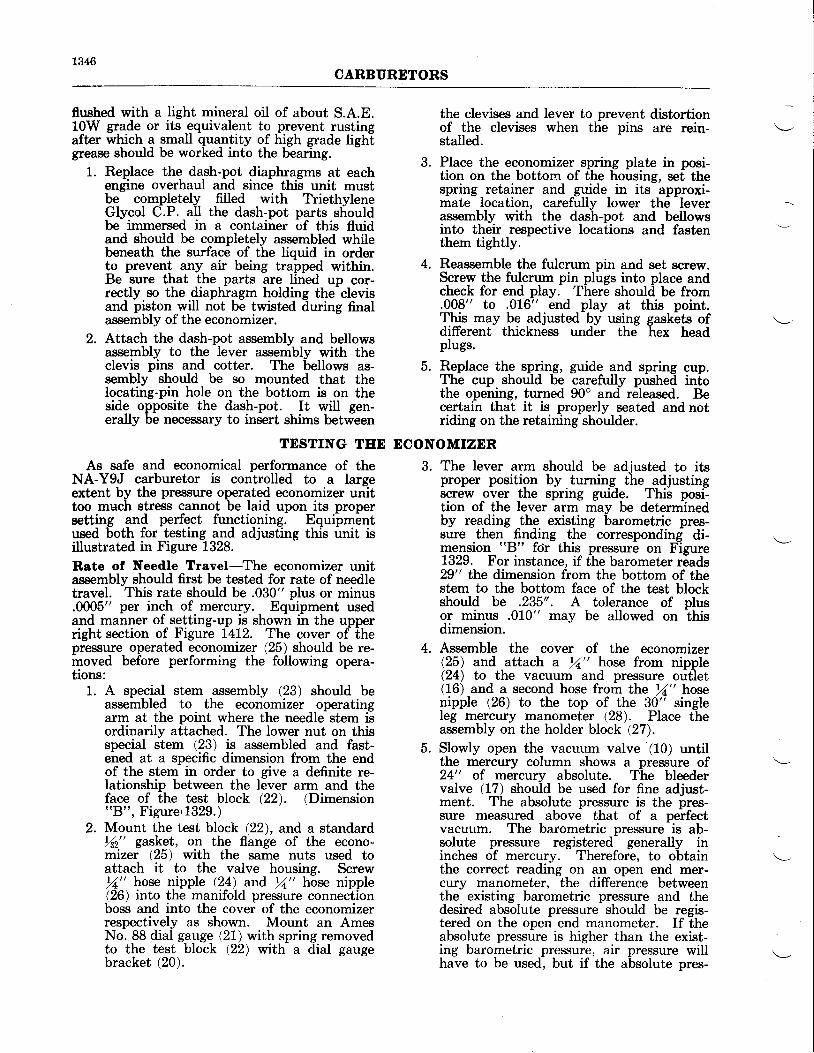
1346CARBURETORS
flwhed with a Iight mineral oil of about S.A.E.10W grade or its equivalent to prevent rustingafter which a small quantity of high grade lightgrease should be worked into the bearing.
L. Replace the dash-pot diaphragms at eachengine overhaul and since this unit mustbe completely filled with TriethyleneGlycol C.P. all the dash-pot parts shouldbe immersed in a container of this fluidand should be completely assembled whilebeneath the surface of the liquid in orderto prevent any air being trafped within.Be sure that the parts are lined up cor-rectly so the diaphragm holding the clevisand piston will not be twisted during finalassembly of the economizer.
2. Attach the dash-pot assembly and bellowsassembly to the lever assembly with theclevis pins and cotter. The bellows as-sembly should be so mounted that thelocating-pin hole on the bottom is on theside opposite the dash-pot. It will gen-erally be necessary to insert shims between
the clevises and lever to prevent distortionof the clevises when the pins are rein-stalled.
3. Place the economizer spring plate in posi-tion on the bottom of the housing, set thespring retainer and guide in its approxi-mate location, carefully lower the leverassembly with the dash-pot and bellowsinto their respective locations and fastenthem tightly.
4. Reassemble the fulcrum pin and set screw.Screw the fulcrum pin plugs into place andcheck for end play. There should be from.008" to .016" end play at this point.This may be adjusted by using gaskets ofdifferent thickness under the hex headplugs.
5. Rgplace the spring, guide and spring cup.The cup should be carefully pushed intothe opening, turned 90o and released. Becertain that it is properly seated and notriding on the retaining shoulder.
TESTING TEE ECONOMIZER
As safe and economical performance of theNA-Y9J earburetor is controlled to a largeextent by the pressure operated economizer unittoo much stress cannot be laid upon its propersetting and perfect functioning. Equipmentused both for testing and adjusting this unit isillustrated in Figure 1328.
Rste ol Needle Travel-The economizer unitassembly should first be tested for rate of needletravel. This rate should be .030" plus or minus.0005" per inch of mercury. Equipment usedand manner of setting-up is shown in the upperright section of Figure 1412. The cover of thepressure operated economizer (25) should be re-inoved beiore performing the following opera-tions:
1. A special stem assembly (23) should beassembled to the economizer operatingarm at the point where the needle stem isordinarily attached. The Iower nut on thisspecial stem (23) is assembled and fast-ened at a specific dimension from the endof the stem in order to give a definite re-lationship between the lever arm and theface of the test block (22). (Dimension"B", Figure,1329.)
2. Mount the test blodk (22), and a standardr/s2" gasket, on the flange of the econo-mizer (25) with the same nuts used toattach it to the valve housing. Screw/a" hose nipple (24) and 11" hose nipple(26) into the manifold pressure connectionboss and into the cover of the economizerrespectively as shown. Mount an AmesNo. 88 dial gauge (21) with spring removedto the test block (22) with a dial gaugebracket (20).
3. The lever arm should be adjusted to itsproper position by turning the adjustingscrew over the spring guide. This posi-tion of the lever arm may be determinedby reading the existing barometric pres-sure then finding the corresponding di-mension "B" for this pressure on Figure1329. For instance, if the barometer reads29" the dimension from the bottom of thestem to the bottom face of the test blockshould be .235'. A tolerance of plusor minus .010" may be allowed on thisdimension.
4. Assemble the cover of the economizer(25) and attach a rZ" hose from nipple(24) to the vacuum and pressure outlet(16) and a second hose from the )1" hosenipple (26) to the top of the 30" singleleg mercury manometer (28). Place theassembly on the holder block (27).
5. Slowly open the vacuum valve (10) untilthe mercury column shows a pressure of24" of mercury absolute. The bleedervalve (17) should be used for fine adjust-ment. The absolute pressure is the pres-sure measured above that of a perfectvacuum. The barometric pressure is ab-solute pressure registered generally ininches of mercury. Therefore, to obtainthe correct reading on an open end mer-cury manometer, the difference betweenthe existing barometric pressure and thedesired absolute pressure should be regis-tered on the open end manometer. If theabsolute pressure is higher than the exist-ing barometric pressure, air pressure willhave to be used, but if the absolute pres-
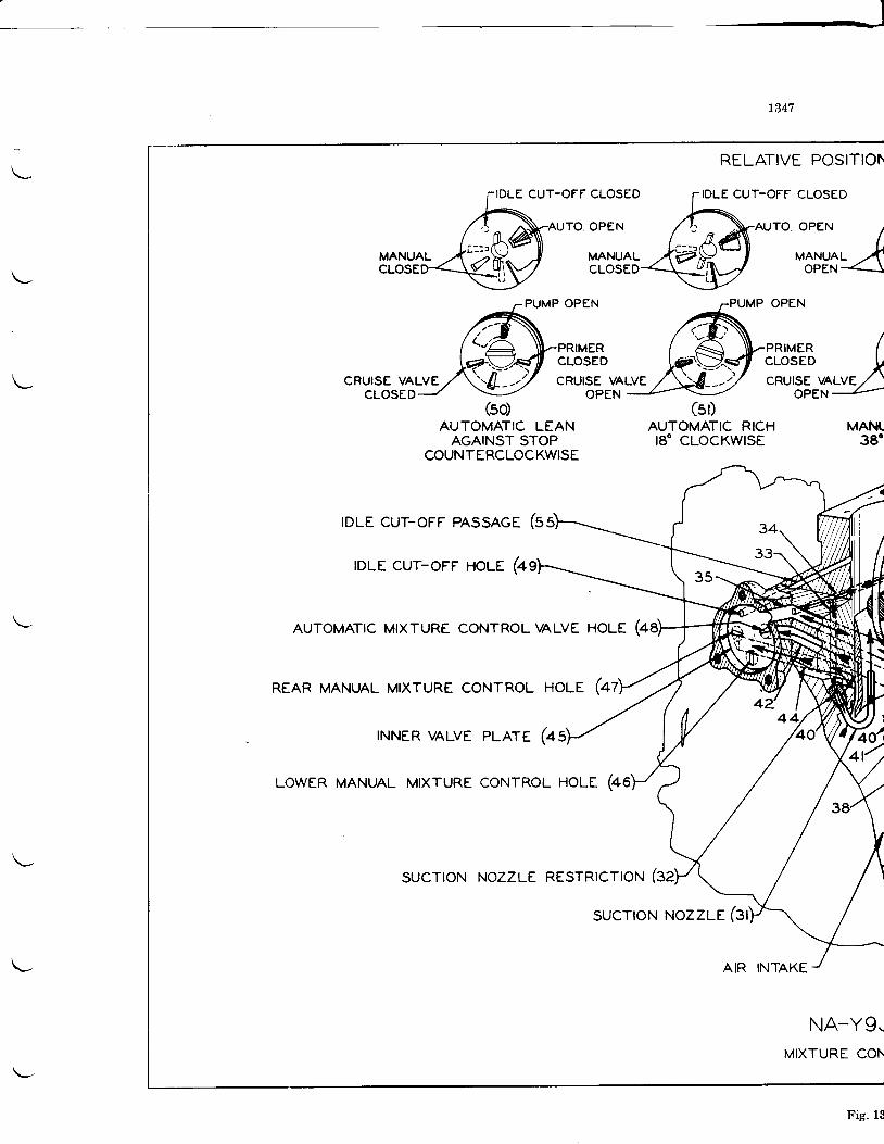
- l
L347
RELATIVE POSITIOh
CUT-OFF CLOSED rIDLE CUT-OFF CLOSEDT|ULE LU r - (Jr r LL(JSLU
AUro oPEN A-AUro
.PEN /
ytlyt^L .\vp-l ,o*Yi{cuoseo<\!$/ oPE
PUMP OPEN
PRIMERCLOSED
CRUISE VALVEOPEN
(so)AUTOMATIC LEAN
AGAINST STOPCOUNTERCLOCKWISE
IDLE CUT-OFF PASSAGE 6
rDLE CUT-OFF HOLE (4
AUTOMATIC MIXTURE CONTROL VALVE
REAR MANUAL MIXTURE CONTROL HOLE (4
(st)AUTOMATIC RICHI8 'CLOCKWISE
AIR INTAKE
MANIL38"
NA*Y9-MIXTURE CON
INNER VALVE
LOWER MANUAL MIXTURE
PLArE (4
CoNTROL HOLE (46
sucrroN NozzLE RESrRtcrloN (32
sucroN NozzLE (31
PRIMERPRTMER (cLosED xcRUlsE UALVE/ '
OPEN
Fig. 13
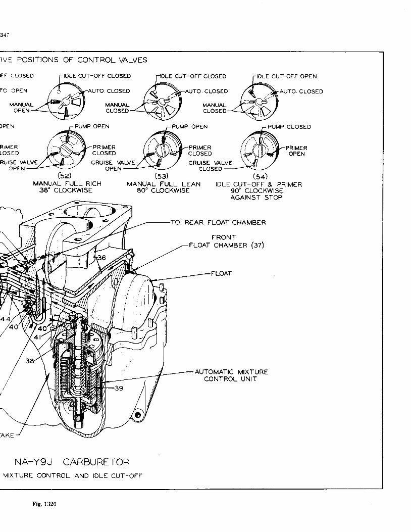
FF cl-oSED rIDLE CUT-OFF CLOSED'";il=&JAUTO. CLOSED
MANUAL ,,{'-4V-.] I MANUALopEN<.- \ -D
/ cLosED
3{;
IV5 POSITIONS OF CONTROL VALVES
CU.r-OFF CLOSED
AUTO. CLOSEO
MANUALCLOSED
OPEN
PRIMERCLOSED
IDLE CUT-OFF
AUTO
PUMP CLOSED
PRIMEROPEN
OPEN
CLOSED
)PEN
R I M E RTOSED
PUMP OPEN
PRIMERCLOSED
RI]ISE VALVE CRUISE VALVECPEN OPEN
$z)MANUAL FULL RICh
38' CLOCKWTSE
AKE
NA_Y9-I CARBURETORMIXTURE CONTROL AND IDLE CUT_OFF
CRUISE VALVECLOSED
MANUAL FULL LEAN IDLE CUT-OFF & PRIMER80'cLocKWtsE 90" cLocKwtsE
AGAINST STOP
TO REAR FLOAT CHAMBER
FRONTFLOAT CHAMBER (37)
FLOAT
AUTOMATICCONTROL
MIXTUREUNIT
(sg)
Fig. 1326
1349CARBURETORS
sure desired is lower than the barometricpressrure, vacuum should be used. Forinstance, if it is desired to rcg1ster 24"absolute pressure and the existing baromet-ric pressure is 29.2", we subtract 24" from29.2" and find the difference is 5.2" whichwill have to be registered on the open endmercnry manometer. Since t}ne 24" abso-lute pressure is lower than the 29.2" baro-metric pressture, the5.2'of mercury must bevacuum. Note the Ames No. 88 DialGauge (21) reading at24" mercury absolutepres{rure but before taking the reading tapthe economizer (25) several times with asmall fiber mallet. Close the vacuum valve(10) and take the Ames reading at atmos-pheric presrilrre. Transfer the hose fromlhe top-of the mercury manometer (28) tothe bottom or weII (to register pressure)and leaving vacuum valve (10). closed,open au presnure valve (11) and take Amesdial gaugb readings at several intervals upto 48" mercury absolute.
6. The rate of travel of the needle shouldnow be computed by dividing the travelbetween the various points by the numberof inches of change in pressure and if itproves to be less than .030" plus or minus.0005" per inch of mercury the spring cupshould be removed and the spring un-screwed somewhat from the screw andguide. The reverse procedure should beused if the rate proves to be too high.
7. When the number of coils on the springguide and screw, are changed it becomesnecessary to readjust the screw above thespring to obtain the correct dimensionr$tr.- After this the rate should be re-checked.
8. After the Pressure Operated Economizer(25) has undergone test for rate of needletravel it should be removed from theholder block (27) and the test equipment(20), (2L), (22), (23), and (24) removed.Leave the one nipple (26) installed.
Reaseembly of Eoonomlzer Unlt to Carbure-tor-Insert the economizer packing in its recessin the top of the Economizer Valve housing,add the gasket and fasten the Economizer Unitto the Valve Body with the five hex nuts andwashers provided. Now screw the economizerneedle aid seat into place, guiding the end ofthe needle stem through the hole in the end ofthe operating arm and fasten with the nut. Itmay be necessary to assemble more than onewasher under this castle nut to raise it highenough to lock-wire it to the end of the stem.Replace the cover. The entire unit and valvehotising may now be assembled to the carbu-retor.
Preparlng Carburetor lor Further Econo-mlzer Tests-The test set-up as sketched inthe main part of Figure 1328 is used in allfollowing tests:
1. Remove the main, economizer and cruisevalve metering jets and replace withblank jets. Plug the fuel inlet boss.
2. Remove the hex head plug from the econo-mizer unit cover and insert gauge holder(39). Assemble an Ames No. 88 dialgauge (32) (with the spring removed)together with gauge extension (40) intothe gauge holder (39) and fasten with thegauge clamp (37).
3. An air hose can now be attached fromvacuum and pressure outlet (16) to themanifold pressure connection on the unitthrough f" hose nipple (19), LA" piptee (36) and. rf" close pipe nipple (35).A second hose is connected ftom the rfi"pipe tee (36) to the top of the Ames No.BA aiA daube (32) wliere it is attachedby hose fitting (31).
4. Remove the plug from below the econo-mizer needle valve and replace with theadapter elbow (33), the regular gasket(41) and a /2" hosr- fitting (34) from whicha L/2" hosr- (9) runs to air valve (4).
5. In order to secure exact readings and toovercome . any slight sticking tendenciesof the moving parts a pneumatic vibrator(29) is attached to the carburetor flangewith a (30) vibrator plate and is connectedto the air source through the air pressurevalve (18).
Leakoge Test-A test should be made forIeakage from the pressure operated economizerunit tlo the float cliamber of ihe carburetor pasteither the needle or the seat. Leakage of thistype will cause the carburetor to flow erratically.
1. Connect a rZ,, hose from the r/,, hosr-nipple (38) on the economizer to theWeil or Bottom of the 30" single leg mer-cury manometer (28).. (This wiU, regrste.rair pressure greater than atmospheric airpressure.) Open the air valve (4) soitrat it c6nnects the manometer (2) to thetesting hose (9) but not to the air adjust-ing box. Set the carburetor mixture con-tr6l in the "Manual FulI Rich" position.Open the air pressure valve (18) to startthe pneumatic vibrator (29).
2. Slowly open the air pressure valve (11)until the mercury manometer (28) reg-isters a pressure of 38" of mercury absolute.(Barometric plus manometer reading.) Caremust be taken not to open the air pressurevalve (11) either so far or so rapidly thatthe mercury is blown out the mercury tube.
1350CARBURDTORS
3. The water column in water manometer(2) should be observed closely while themixture control is rotated from the "Man-ual Full Rich" to the "Manual Full Lean"position. If a slight rise in the water col-umn is noticeable, a leak is present andthe rubber packing around the seat be-tween the economizer body and the valvehousing should be replaced.
Openlng Pollt-'The economizer is set to openat a predetermined engine manifold (blower rim)pressure rather than at a set throttle valve-position
as in the conventional carburetor. Thei,p"trirg point should be checked and set asfollows:
1. Determine from the carburetor specifica-tion sheet whether the economiZer willstart to open above or below the existingbarometric pressure. If it wiU open belowconnect the hoqe from the r/" l{o* nipple(38) to the TOP of the nnercury mano-fnglgl (r.Q. (Exactly as shown iir Figure1328.) If the opening point is found to beabove the existing barometric pressure thehose should be attached to the bottom orwell of the mercury manometer (28).
2. Turn air valve (4) so that the water mano-meter (2) is connected to the air adjustingbox but not to the air hose (9). The airbleeder (6) should be a No. 5 and the airvalves (5), (13), (14), should remain closed.
3. Open tlre air pressure valve (1) allowingair to flow into the surge tank (15) andby means of the air pressure reducer valve(8) adjust the air pressure to registerabout 8-10 pounds pressmre on the dialpre$ilue gauge (3). Slowly open the airadjwting needle (12) until the watercolumn in the water manometer (2) standsat 42.4". Start the pneumatic' vibrator(2e).
4. Turn the air valve (4) to connect both thehose (9) and the water manometer (2)to the air adjusting box. If the econo-mizer needle is closed the water columnwill not change but if the needle hasstarted to open the water column willdrop. The water column should start todrop from the 42.4" point just as the ab-solute pressure in the economizer exceedsthe absolute pressure listed on the car-buretor specification sheet as the econo-mizer setting. For instance, if the econo-mizer is to open at 27.5" and the existingbarometric pressure is 28.6" the needle
should just open al_tlg qressyle in theeconomizer reaches 27.5" abs. (1.1" read-ing of the mercury manometer) and thewater column will start to drop.
5. If the needle opens at too low a pressureremove the cover of the economizer, andscrew the needle up through the lever,then reassemble the cover and recheckthe point. If it opens too high, the needleshould be screwed down.
Over-rlde-After adjustment of the economizeropening point is completed the economizer valveover-ride spring opening should be checked.
1. The same equipment and set-up employedin the previous test should be used. Thewater column should be set to 42.2" andthen the air valve (4) opened to the hose(9), water manometer (2) and the airadjusting box.
2. The vacuum valve (10) should be slowlvopened and the watei c6lumn in the wate-rmanometer (2) closely watched. Theheight of the mercury column in themercury manometer (28) should be ob-served when the water column starts todrop. This drop indicating the over-rideopening should take place between 10"and 15" of mercury absolute pressure. Ifthe spring operur outside these limits itshould be replaced.
Rate of Travel Check-The rate of needletravel should be hastily rechecked after theeconomizer has been tested and adiusted. Itwill be necesszuy to check the rate oniy from theopening point up to 38" of mercury absolute.The gauge extension (40) rests upon the operat-ing lever directly above the bellbws and as thedistance from this point of contact to the fulcrumpin is just 1/3 the distance from the needle tothe fulcrum pin the rate of travel should bedivided by 3 to obtain the correct reading on theAmes dial gauge (32).
If the readings obtained by this check do notcoincide with those made on the test block theneedle and seat should be closelv examiried fordistortion or for any particles of foreign mattgrwhich would tend to cause a binding action.
When all checks have been completed, thecover should be removed and the spring andneedle adjusting screw locknuts carefully tight-ened and lockwired. All blank jets previouslyinserted in the carburetor should be replacedwith the proper size metering jets and the car-buretor completely assembled.
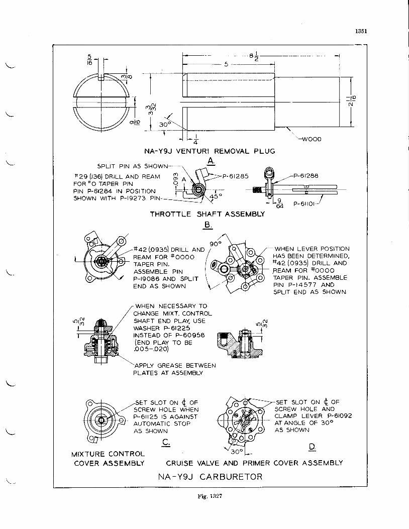
1351
NA-YgJ VENTURI REMOVAL PLUG
SPLIT P IN A5 SHOWN
*29 { .136) DRTLL AND REAMFOR 1+O TAPER PINPIN P-6I284 IN POSITIONSHOWN WITH P-I9273 PIN
P - 0 t 2 e 5
THROTTLE SHAFT ASSEMBLY
B .
+az (osss) DRTLL ANDREAM FOR +OOOO
TAPER PIN.ASSEMBLE PINP- Ig086 AND SPL ITEND AS SHOWN.
WHEN LEVER POSITIONHAS BEEN DETERMINED,+az (.os:s) onul aruo8EAM FOR +IOOOO
TAPER PIN. ASSEMBLEP I N P . I 4 5 7 7 A N DSPLIT END A5 SHOWN.
WHEN NECESSARY TOCHANGE MIXT. CONTROLSHAFT END PLAY USEWASHER +61225INSTEAD OF P-60958(eruo prav ro BEbos-.ozo)
Y GREASE BETWEENPLATES AT ASsEMBLY
r sLor oN { oF sET SLOT ON c OFSCREW HOLE WHENP-6i l25 15 AGATNSTAUTOMATIC STOPA5 SHOWN
SCREW HOLE ANDCLAMP LEVER P-6IO92ATANGLE OF 3OOA5 SHOWN
c. DMIXTURE CONTROLCOVER ASSEMBLY
? n o
CRUISE VALVE AND PRIMER COVER ASSEMBLY
N A - Y g J C A R B U R E T O R
Fig. 1327

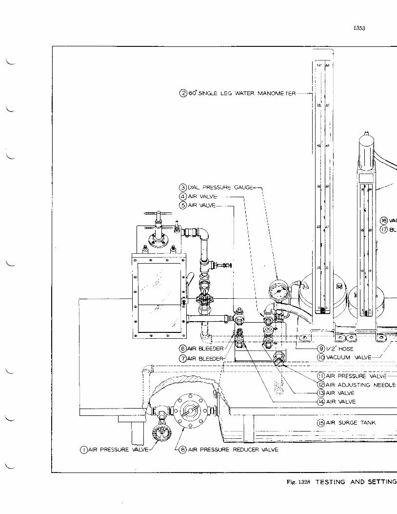
1353
@vN@ ",-
@arn sURGE rANK
Fig.1328 TESTING AND SETTING
tI
t{llffi
T]SUREPRES
VALVE
VALVE
@oral@nrn@nrn
@arn@nrn BLEEDER,'
1-@aia PnEssune GlvE--\ t l i /^" ' ' ' ' '
\ )@arn ADJUSTNG NEEDLE\-�---@AIR VALVE
AIR VALVE
@nrn PRESSURE AIR PRESSURE
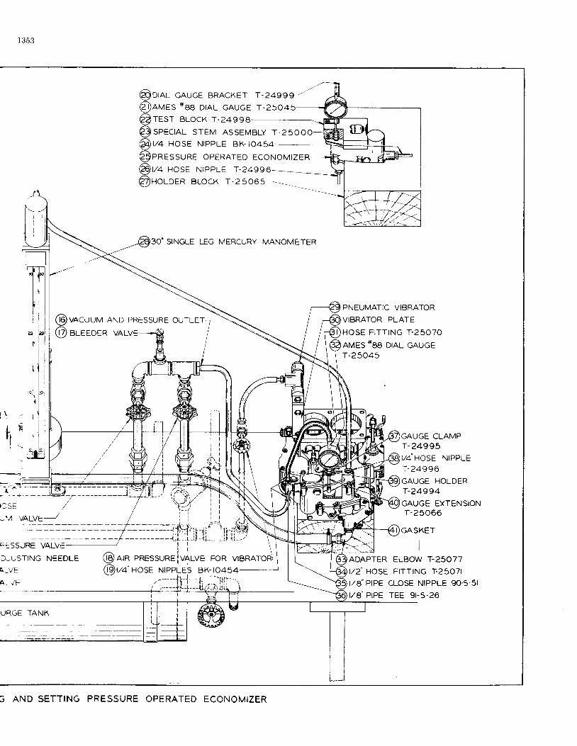
l 353
@va nose NTPPLE T-24996
@noloen BLocK r -25o6s
30" SINGLE LEG MERCURY MANOMETER
I :SE
-.7 y41yE-----z
C:SSURE VALVE
D-USTING NEEDLE
ATVE
A- , /E
URGE TANK
PNEUMATIC VIBRATOR
VIBRATOR PLATE
HOSE FITTING T.25070
AMES "88 DIAL GAUGE
T-25045
@vacuuv AND PRESSURE ourLEr
@ e,-eeoen vALVE
l t r
@nrn PRESsuREivALVE FoR vTBRAT
@v+' HosE NTPPLES BK-ro454-ADAPTERt, /2 'HOSEt/A" PtPEt/8"PIPE
GAUGE CLAMPT-24995
I/4 HOSE NIPPLEr-24996GAUGE HOLDERT-24994
GAUGE EXTENSIONT - 2 5 0 6 6
GASKET
IELBOW
'r-25077
FITTING I .25O7I
CLOSE NIPPLE 9O.5.5I
I t rE y r ->-zo
3 AND SETTING PRESSURE OPERATED ECONOMIZER
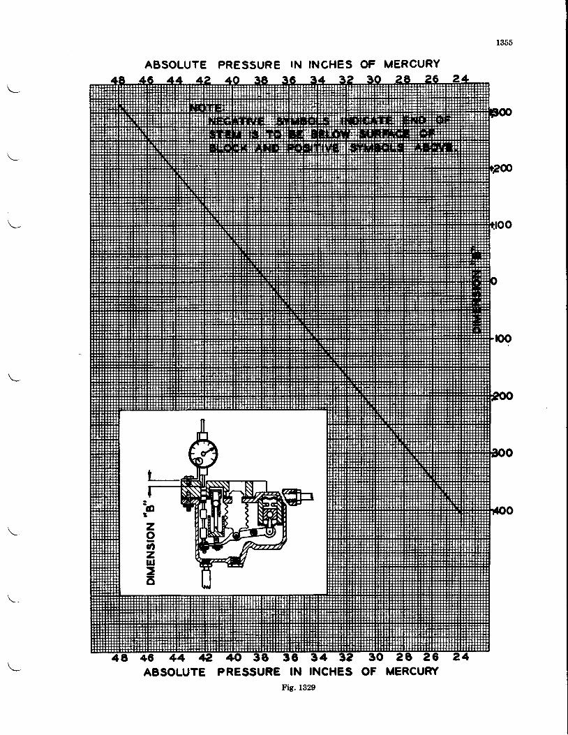
ABSOLUTE PRESSURE IN INCHES OF MERCURY
ABSOLUTE PRESSURE IN INCHES OF MERCURYFis. 1329
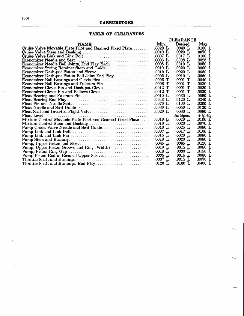
1356CARBURDTORS
TABLD OF CLEARANCDSCLEARANCE
NAME Min. Desired Max.Cruise Valve Movable Plate Pilot and Reamed Fixed Plate .0020 L .0040 L .0100 LCruise Valve Stem and Bushing. .0010 L .0020 L .0070 LCruise Valve Link and Link Bolt. .0007 L .0017 L .0100 LEconomizer Needle and Seat. .0006 L .0008 L .0025 LEconomizer Needle Ball Joints, End Play Each. .0005 L .0010 LEconomizer Spring Retainer Stem and Guide .0010 L .00.20 LEconomizer Dash-pot Piston and Sleeve. .0010 L .0020 LEconomizer Dash-pot Piston Ball Joint End Play .0005 L .0010 LEconomizer Ball Bjearings and Clevis Pins. . .0006 T .0001 TEconomizer Ball Bearings and Fulcrum Pin. . . .0006 T .0001 TEconomizer Clevis Pin and Dash-pot Clevis. .0012 T .0001 TEconomizer Clevis Pin and Bellows Clevis. .0012 T .0001 TFloat Bearing and Fulcrum Pin. . . .0010 L .0030 LFloat Bearing End Play.. .0043 L .0120 LFloat Pin and Needle Slot. . .0070 L .0100 L
.0050 L
.0060 L
.0050 L
.0050 L
.0040 L
.0030 L
.0020 L
.0020 L
.0090 L
.0240 L
.0200 LFloat Needle and Seat Guide .0030 L .0050 L .0120 LFloat Seat and Inverted Flight Valve. .0020 L .0030 L .0080 LFloat Level As Spec. +344-144Mixture Control Movable Plate Pilot and Reamed Fixed Plate. . . . .0010 L .0020 L .0100 LMixture Control Stem and Bushing. .0010 L .0020 L .0070 LPump Check Valve Needle and Seat Guide. .0010 L .0025 L .0080 LPumb Link and Link Bolt. .0007 L .0017 L .0100 LPump Link and Link Pin. .0015 L .0020 L .0080 LPumb Stem and Bushing. .0010 L .0020 L .0080 LPump, Upper Piston and Sleeve. .0045 L .0C65 L .0120 LPump, Upper Piston Groove and Ring (Width) .0010 L .0015 L .0060 LP u m b , P i i t o n R i n g G a p . . . . . . . 0 0 1 0 L . 0 0 3 0 L . 0 1 5 0 LPumi'Piston Rodtin R-eamed Upper Sleeve. .0005 L .0015 L .0080 LThro^ttle Shaft and Bushings . .. .'. . .000? L .0015 L .00?0 LThrottle Shaft and Bushings, End Play .0L20 L .0160 L .0400 L
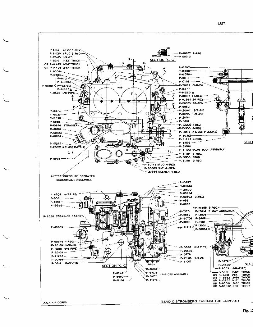
^-.e=6o6"J
z-REQ'
sEcTroN "G-G"
P_t65e7----P-
P-6ll l2-
P-20r67 B/A-?4
//P-114773 A
A P-6or5o r lP-60244 24-RE6l.- --
tr P-2O355 2O-REQ
-P-20t67--P-61195
,-P-2016453r0
-P-22232 4REQ.
D P-6O3r2--P-ara54 z-REO.
Q/a-24I/4-2Al
xP-ro455P-r7C14 F|-OATP-r3tegP-606€P-3t99
(t/a PtPe)
\t/426].
L357
F-3779P-P-a505 v4-PP-5AAr V3Z"P-t528t V64"P-t5?62 3t64-P-t5263 l /16 'P-6006t .o lo 'P-60062 .O20
P-5319 t . /32" THrCKoR P-t4425 l/64"THlCKoR PJ4426 3/64-TH|CK
P-9008P-r76@
P-A506 { r /6 -P lA
P- i l47
P- 13733P-r7690P-6069- =_-P-15974 STRAINER
A
1e-orro-i\_lI P-6I2O6A\ \-
e-orroo j n-rsezsa-\(1e-eteasa-
-\i
P-0ro97P-40�4,,2P-r4660
---_-- --P-1535O GREQ.-r I P-2o5r3 (A.c.usE P-22242),
P-r5205P-20376rAC.USE Fr76
P-900t
P-8506 0 /EPTPE)
F-65at-- - -P- 6€66P-r5236
P-6556 STRAINER GASKET.
P-60049-
P-60346P-20r66P-a508P- 20to9P-2t206P-20r64P- 5310
I-REQ(3A6-?6,)
(VE PIPE)
* _P_6tO66
I r=-F6llO3 vALvE Bclot ASS€MELY
\H--=._- - - P - O l l t O 2 - R E Q
-l==-Eeoras sruD 4-REe//
,/A-I7736l PRESSURE OPERATEO
ECONOMIZER ASSEMBLY
-'\\p-oogog NUT 4-"REe.
\P.2O3O4WASHER 4-REQ.
P-r3A77P-60434
,'/P-717O,,' -P-CoO7
20r70P-60.234�
P-654rP-CC60
60?p6P-6lO9l
65002t430�3779
-P-61067sEcI
r pe)T H I C KT H I C KTHICKT H I C KTHICKT H I C X
ORO ROROROR
P-60421P-
6 r 0 6 2 l
3i31? 1"-t'"'2 A''EMBLY
61075 )
A .C. . A IR CORPS.
P-6 t l04
BENDIX STROMBERG CARBURETOR COMPANY
Fig. 1!
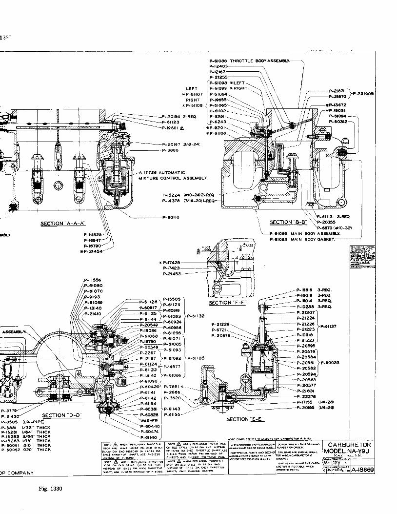
l ; l ; ;
Ass€MaL
F- 3779P-2t4
f,l){io}e-zzaox
*P-t9031FCtOO.lF-CO3r2
2Ot67 p/A-24)
8880
7725 AUTOMATICMIXTURE CONTROL ASSEMBLY
P-t5224P-K374
.P-00ilo
(*ro-24\?-REQ.-
o/r0-2o) |-REQ;
SECTION -A-A-A'
P-|4�A25
P-r0790xP-21454
sEcrtoN "F-F'
P-222eP-6721P-20574
MAIN BOOY ASSEMA-Y
P-6IO63 MAIN AOOY GASXET.
P-r86lC 3-REQ.3+€Q.}REQ.
3.REQ.
_--P-raor4
_P-2t24
*P-t74e-17423___P-21453--
il5566roao
o70o r930t069r31402t4ro
P-2t226P-2t225P-roe ra
P-205e5
--P-205e3-P-20577
-=\P-et63t
P-22276P-f7f55 (W-26P_2Ot65 (tra{g
e-aosrelP-2o584 IP-zosar lP-cooz3P- 20582
|P-20504)
sEcrtoN "D-D"
lrze-eree)t/32" TH|CKy64" TH|CK3/64- THrCKr/ t6" THtcK.oto rHrcK.o20" THrcK
P-A505
P- 5661P-r5261F-t 5202P-r5243P-60061P- 60062
P-OIOEo THROTTLE BOOY ASSEMBLYP-t 2403P-t2t67F2r255
(retoee xLEFT-LEFr I e-e,oee xRrGHr
*P-6 i lO7 l P-6rO04-RrGHr I p-re65s--\.- - . . ^^ / ̂ - . ^ - - - \ - -
\ \ , 'Foi l13 aREQ.SECTION'B-B \P-zo3ss'P-6670 (*lo-32)
CARBURETORMODEL NA-YgJ
rc^La. r l lL s rz€ .
NorE A wN REPL&|NG morrG
STOP A@ PUMP L€VER ON OLO SYYLE(r /3e ua ED |N5TE& G r1 l !2 o r^
er€ Z\ wN tirurc ra.orrLEsrOP d o lo s tY !€ ( r r l !2 o r^ €sr {$@ G rJ / !2 )A €S) i lFOtTLE
sFls. oMrr p-6r206 wash*
S ioP or 40 s rYLE { | ,32 o la E{orNST€AO OF r t l32 d^ ENO) THPqTLE
sHAFt . US P- r$7O TNsTEAO S P-d?65.)F COMPANY
Fig. 1330
SECTION E-E''
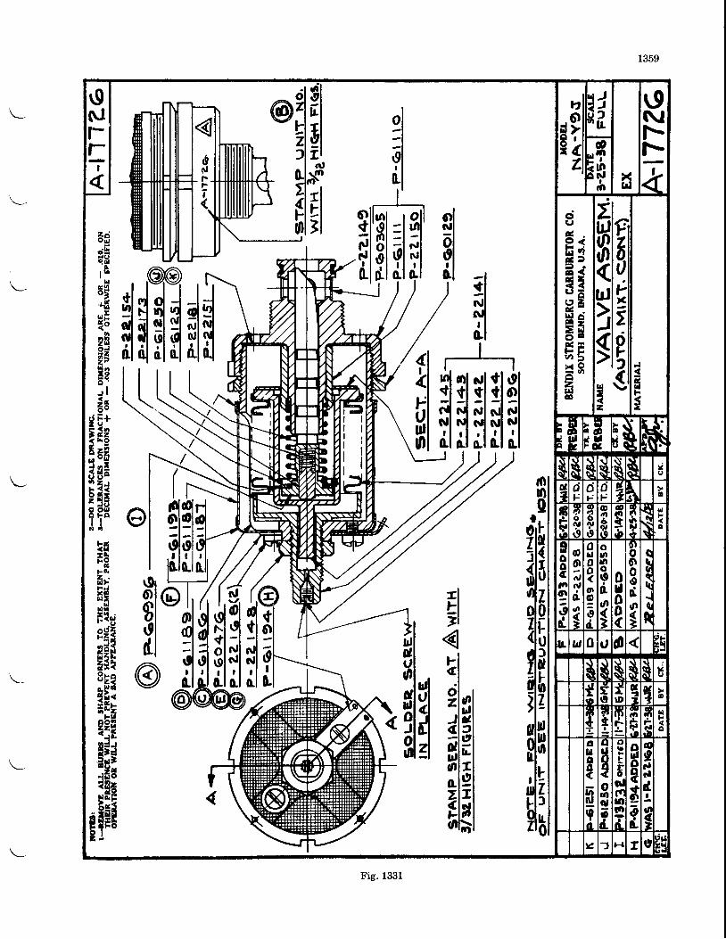
1359
olNl
ol
tl
el' l
flT|i$
o{
$I
d"l
ffidlol:let0.1
@
@
$l
!6aeEEFl l .
5H+6
lE?$a3;e, r l8rgE+
F < ' ', 2 2< E O
5af3nEFEi; d E?T"N A
4[lHq
,/L,fiflflililfl
tlr-l7l
FIal
zlnJldc l 3"rllolgzlrflsd'h
n). o l
E?Izl
lixld
19Nf-ft-z
ot ?t$il
dtc9 <E33 a7 7r , E2 aH 9E sHg= 9ozr||F
file(lq
5lFstgi sz
rl{&l||F
E
!frr E
$lI. E, r8- c ,.s
u(,
d1
dt-
cjj-
aF' G
nrCcil
4oNa'a
I
Iryo
oa6il
ct1rqq
(R
uF
A
Eooctt!I3d.
oIt\,at
Go(-
ocooo|I0d-
oolrloona{
0ld00(
oooodog
L u 0 t a*
frtt
$$I
tf f
IDa.'I
E
I
IttI
t6
F.lt.
o!loo((tIed
691rld
dLurE
gl
A
ald!o
V,u,o
a
o
farl
8ornood
raF
!Folff)nlrr
d_a f H x 0 ttl
Blt
Fig. 1331
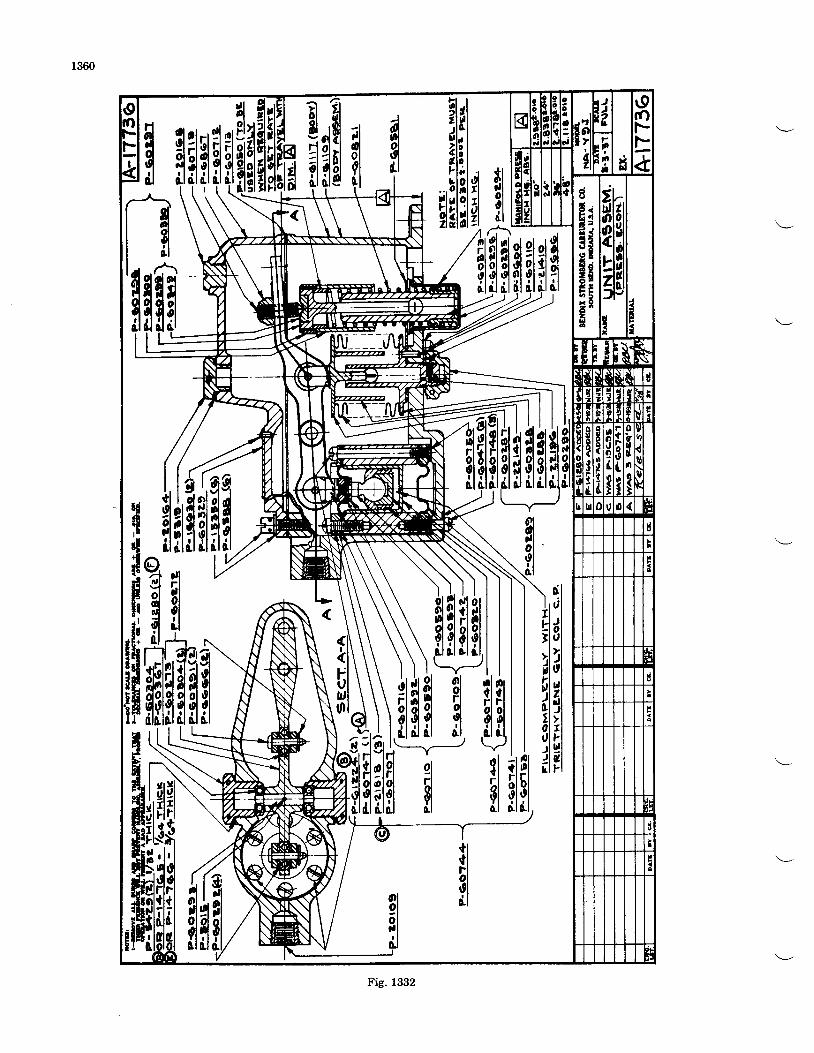
1360
r lolqdl
flol
dqololt l
LI
ol4glt l
ot '0lr l
GI
*tlcl Idt I
fiflet 9l0.t 0,1
0l
iltl
RlSl {l 0,1
?tr;trt-li
.,b13
H[|;slHiflfl#u
dl
gr l0.1
gs,
flf,
5lil
olflrtlil
?it
6l
il4iII:
4 4l o, ,
I
tifir f il
ofol'-F-L
riz9 <
E39 .t <e a; tE d= 66 rE Eo >
= e2d
frhflias
II
t
Nudltsi l l
tlil6t! ii l&l
l0o\,!(
3da
IA
lil#tusllrlsl
lltlllililil
J
t
ililil xl il ilill.--{l{ lrlol0ldlsl
3ldlffiilil ni
Fig. 1332
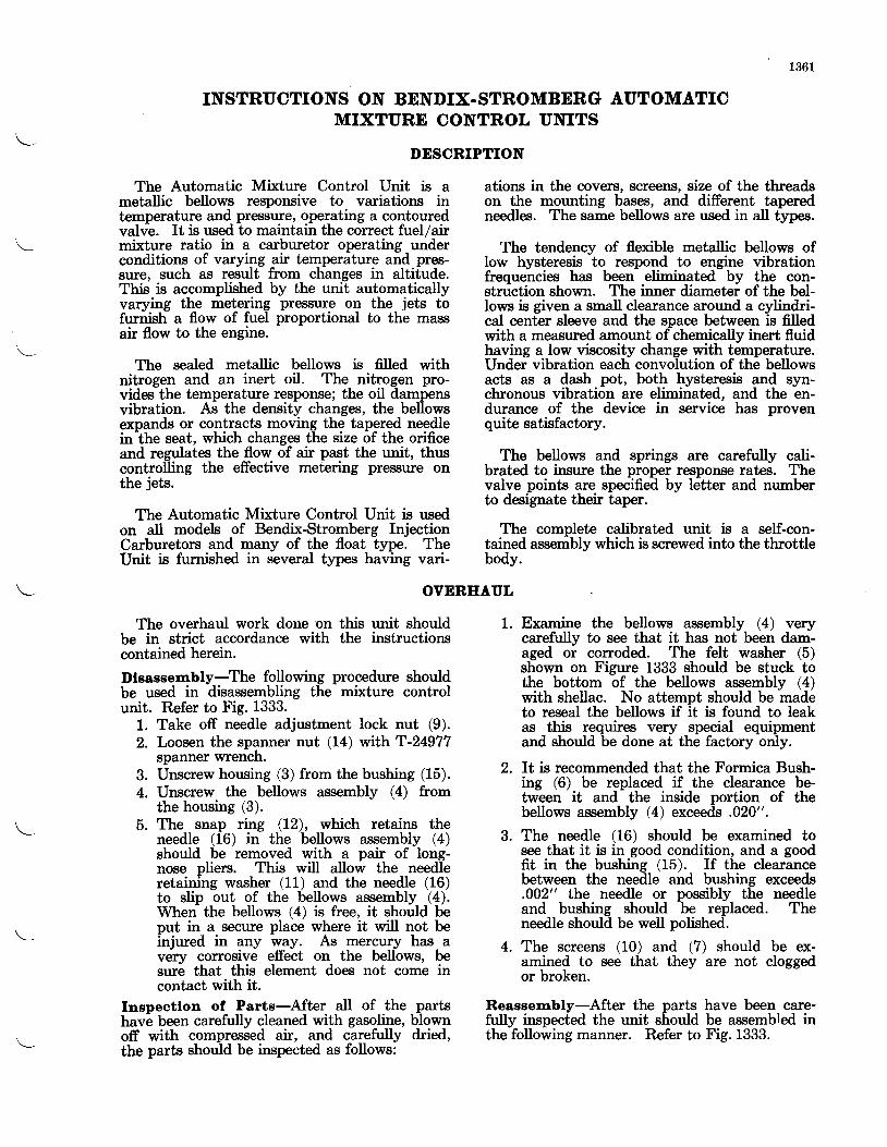
1361
INSTRUCTIONS ON BENDIX-STROMBERG AUTOMATICMIXTURE CONTROL UNITS
DESCRIPTION
The Automatic Mixture Control Unit is ametallic bellows responsive to variations intemperature and pressure, operating a contouredvalve. It is used to maintain the correct fuel/airmixture ratio in a carburetor operating underconditions of varying air temperature and pres-sure, such as result from changes in altitude.This is accomplished by the unit automaticallyvarying the metering pressure on the jets tofurnish a flow of fuel proportional to the massair flow to the engine.
The sealed metallic bellows is filled withnitrogen and an inert oil. The nitrogen pro-vides the temperature response; the oil dampensvibration. As the density changes, the bellowsexpands or contracts moving the tapered needleinlhe seat, which changes the size of the orificeand regulates the flow of air past the unit, thuscontrolling the effective metering pressure onthe jets.
The Automatic Mixture Control Unit is usedon all models of Bendix-Stromberg InjectionCarburetors and many of the float type. TheUnit is furnished in several types having vari-
ations in the covers, screens, size of the threadson the mounting bases, and different taperedneedles. The same bellows are used in all types.
The tendency of flexible metallic bellows ofIow hysteresis to respond to engine vibrationfrequencies has been eliminated by the con-struction shown. The inner diameter of the bel-lows is given a small clearance around a cylindri-cal center sleeve and the space between is filledwith a measured amount of chemically inert fluidhaving a low viscosity change with temperature.Under vibration each convolution of the bellowsacts as a dash pot, both hysteresis and syn-chronous vibration are eliminated, and the en-durance of the device in service has provenquite satisfactory.
The bellows and springs are carefully cali-brated to insure the proper response rates. Thevalve points are specified by letter and numberto designate their taper.
The complete calibrated unit is a self-con-tained assembly which is screwed into the throttlebody.
OVEREAUL
The overhaul work done on this unit shouldbe in strict accordance with the instructionscontained herein.
Dlsassembly-The following procedure shouldbe used in disassembling the mixture controlunit. Refer to Fig. 1333.
1. Take off needle adjustment lock nut (9).2. Loosen the spanner nut (14) with T-24977
spanner wrench.3. Unscrew housing (3) from the bushing (15).4. Unscrew the bellows assembly (4) from
the housing (3).5. The snap ring (12), which retains the
needle (16) in the bellows assembly (4)should be removed with a pair of long-nose pliers. This will allow the needleretaining washer (11) and the needle (16)to slip out of the bellows assembly (4).When the bellows (4) is free, it should beput in a secure place where it will not beinjured in any way. As per9u5,r has avery corrosive effect on the bellows, besure that this element does not come incontact with it.
Inspeotlon of Parts-After aII of the partshave been carefully cleaned with gasoline, blownoff with compressed air, and carefully dried,the parts should be inspected as follows:
1. Examine the bellows assembly (4) verycarefully to see that it has not been dam-aged or corroded. The felt washer (5)shown on Figure 1333 should be stuck tothe bottom of the bellows assembly (4)with shellac. No attempt should be madeto reseal the bellows if it is found to leakas this requires very special equipmentand should be done at the factory only.
2. It is recommended that the Formica Bush-ing (6) be replaced if the clearance be-tween it and the inside portion of thebellows assembly (4) exceeds .020".
3. The needle (16) should be examined tosee that it is in good condition, and a goodfit in the bushing (15). If the clearancebetween the needle and bushing exceeds.002" the needle or possibly the needleand bushing should be replaced. Theneedle should be well polished.
4. The screens (10) and (7) should be ex-amined to see that they are not cloggedor broken.
Reassenbly-After the parts have been care-fully inspected the unit should be assembled inthe following manner. Refer to Fig. 1333.
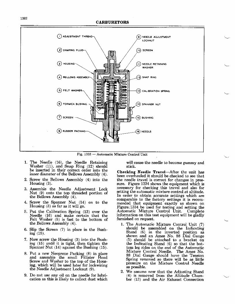
t362CARBURETORS
O aouusruenr NEEDLE ADJUSTMENT
LOCKNUT
SCREEN
NEEOLE RETAINING
WASHER
SNAP RING
CALIBRATION SPRING
SPANNER NUT
B U S H I N G
NEEDLE
@ oeveu.rc r
o(D eeuuows
O rer-r
@ ronurca
O scnee"
@ ^r""t^
Fig. 1333 - Automatic Mixture Control Unit
1. The Needle (L6), the Needle RetainingWasher (11), and Snap Ring (12) shouldbe inserted in their correct order into theinner diameter of the Bellows Assembly (4).
2. Screw the Bellows Assembly (4) into theHousing (3).
3. Assemble the Needle Adjustment LockNut (9) onto the top threaded portion ofthe Bellows Assembly (4).
4. Screw the Spanner Nut (14) on to theHousing (3) as far as it will go.
5. Put the Calibration Spring (13) over theNeedle (16) and make certain that theFelt Washer (5) is fast to the bottom ofthe Bellows Assembly (4).
6. Slip the Screen (7) in place in the Bush-ing (15).
7. Now screw the Housing (3) into the Bush-ing (15) until it is tight, then tighten theSpanner Nut (14) against the Bushing (15).
8. Put a new Neoprene Packing (8) in placeand assemble the small Fillister HeadScrew and Washer to the top of the Hous-ing, which will be used later for lockwiringthe Needle Adjustment Locknut (9).
9. Do not use any oil on the needle for lubri-cation as this is likely to collect dust which
will cause the needle to become gummy andstick.
Checklng Needle Travel-After the unit hasbeen overhauled it should be checked to see thatthe needle travel is correct for changes in pres-sure. Figure 1334 shows the equipment which isnecessary for checking this travel and also forsetting the automatic mixture control at altitude.In order to obtain accurate settings which arecomparable to the factory settings it is recom-mended that equipment exactly as shown onFigurei 1334 be used for testing and setting theAutomatic Mixture Control Unit. Completeinformation on this test equipment will be gladlyfurnished on request.
1. The Automatic Mixture Control Unit (7)should be assembled on the IndicatingStand (6) in the inverted position asshown and an Ames No. 88 Dial Gauge(5) should be attached to a bracket onthe Indicating Stand (6) so that the bot-tom leg rides on the end of the AutomaticMixture Control Needle. The Ames No.88 Dial Gauge should have the TensionSpring removed so there will be as littlepressure on the Mixture Control Needleas possible.
2. We as,sume now that the Adjusting Stand(4) is removed from the Altitude Cham-ber (13) and the Air Exhaust Connection
1363CARBURETORS
3.
4.
5.
6.
7.
(8) and Air Intake Connection (9) areplugged. Now place the Indicating Stand(6), with the Automatic Mixture ControlUnit and Ames Dial Gauge assembled,into the Altitude Chamber (13).
A Pneumatic Vibrator (20) should be at-tached to the top of the Altitude Chamber(13) as shown and this should be startedby opening the Air Pressure Valve (31).
Connect the top of the 30" Single LegMercury Manometer (30) to the nippleon the top of the Altitude Chamber (13)with a /a" rubbet hose so the vacuum inthe Altitude Chamber will be registeredon the Mercury Manometer (30).
Close the door of the Altitude chamber(13) and adjust the vacuum valve (23)and adjustable bleeder (2L) until thevacuum in the altitude chamber (13)which is registered on the mercury mano-meter (30) is equivalent to 28" of mer-cury absolute. NOTE: The absolute pres-sure is the pressure above that of a per-fect vacuum. The barometric pressure isabsolute pressure registered generally ininches of mercury. Therefore, to obtainthe correct reading on the open end mer-cury manometer (30) the difference be-tween the existing barometric presf[rreand the desired absolute pressure shouldbe registered on the open end manometer(30). If the absolute presfrure is higherthan the existing barometric pressure, airpressure will have to bq. used, but if theabsolute pressure desired is lower thanthe barometric prassurg, vacuum shouldbe used.
Record the Ames Dial Gauge reading at28"of mercury absolute pressure. The AmesDial Gauge readings at 23", 16", 13" and10" of mercury absolute presgure shouldalso be recorded.
To find the actual travel of the MixtureControl Needle, the Ames Dial Gaugereading. at 28" absolute pressure shouldbe subtracted from the Ames Dial Gaugereadings taken at the other four absolutepressures. This will give the travel fromthe 28" absolute pressure point to theother four points. The travel of the needleshould be checked to the curve on Figure1335 to see that it is between the low lirnitandhigh limit curves.
If the needle travel does not come withinthe limits shown on Figure 1335 the needleshould be checked to see that it is notsticking or binding or a new spring orBellows Assembly should be installed inthe unit.
Adjustrnent of Unit-The automatic mixturecontrol unit must be properly adjusted beforeit is assembled to the carburetor. The mostaccurate and most satisfactory method is bysetting the unit under the density equivalent toa certain standard altitude. 'fhis procedureconsists of placing the unit in a chamber, whichcan be partially evacuated to the density forthe corresponding standard altitude specifiedon the specification sheet, with a means of turn-ing the adjusting screw on the mixture controlunit so the flow of air past the mixture controlneedle in the unit will be restricted by the needleto such an extent that the water column register-ing this restriction rises to the point specified onthe carburetor specification sheet. This equip-ment is shown in Figure 1334 while the procedurein making the adjustment is outlined below.
1. The Automatic Mixture Control Unit (3)as shown on Figure 1334 should be assem-bled on the Adjusting Stand (4) and thecomplete assembly should be placed in theAltitude Chamber (13).
2. The Hose Connections on the AdjustingStand (4) should be fastened in place tothe Air Exhaust Connection (8) and AirIntake Connection (9).
3. Push the Lock Nut Wrench (14) downover the Automatic Mixture Control Unit(3) so that it engages the Lock Nut (2).Likewise, push Adjusting Screw Wrench(15) down over the end of the adjustingScrew (1).
4. Connect the top of the 30" Single LegMercury Manometer (30) to the AltitudeChamber (13) wrth a %" Rubber Hose.
5. Now close the door of the Altitude Cham-ber (13) and apply vacuum to the cham-ber by adjusting Vacuum Valve (23) andAdjustable Bleeder (21) until the densityin the Altitude Chamber (13), as regis-tered on the Mercury Manometer (30), isequivalent to the altitude specified on thecarburetor specification sheet. For in-stance, if the carburetor specification sheetspecifies that the Automatic Mixture Con-trol Unit is to be set at 20,000 feet standardaltitude density, and the barometer readingat the moment is 29" and the temperatureis 75o F., we refer to the 20,000 foot densitycurve on Figure 1336 and find that it inter-sects the 75" F. point at 16.4" of mercuryabsolute pressture. This 16.4" of mercuryabsolute pressure should then be sub-tracted from the 29" of mercury barometricpressure, to find that L2.6" of mercuryvacuum is the reading on the MercuryManometer (30) which will be equivalentto 16.4" of mercury absolute.
6. Air Valves (24), (I8), (26), and (27) shownon Figure 1334 should be closed and Air
8.
1364CARBURETORS
Valve (25) should be turned so it is openonly to the line running to the bottom ofthe 60" Single Leg Water Manometer (29).
7. Open the Air Pressure Valve (11) so thataii from the Shop Air Pressure Line 1fO;passes through the Air Pressure Fl,educerValve (12) into the Air Surge Tank (28)and up to the Air Adjusting Needle Valve(27). The Dial Pressure Gauge (22) wiUindicate the pressure of the air in theSurge Tank (28) as it is regulated by theAir Pressure Fleducer Valve (12).
8. See that a No. 5 Air Bleeder (16) is installedin the Air Adjusting Valve Block and aNo. 15 Air Bleeder (17) is installed abovethe Air Valve (18).
9. Open the Air Adjusting Needle (27) gradu-ally so that the water in the Water Mano-meter (29) is not blown out of the top ofthe manometer. Now adjust the AirAdjusting Needle Valve (27) and the AirPressure Reducer Valve (12) until the watercolumn in the Water Manometer (29) risegto 42.4" with only the No. 5 Air Bleeder(16) open and so the water column drops toi4.7" when the Air Valve (18) is also opento a No. 15 Air Bleeder (17). This wilrequire a pressmre of approximately 10 lbe.pef square inch as registered on the DialPressure Gauge (22) and as adjwted bythe Air Pressure Fleducer Valve (12). Ifwhen the No. 15 Air Bleeder is openedthe value on the water column is higherthan L4.7" the tank presrrure as registeredon gauge (22) should be lowered slightly andthe 42.4" value reset on the column, usingneedle valve (27). Then it should be re-checked with No. 15 bleeder (17) open tosee that the drop is correct. If the initialreading was lowbr than 14.7" water, thepressure in the tank should be raised andihe check repeated.
10. Now close the Air Valve (18) and openthe Air Valve QQ w that air may flowfrom the Air Adjusting Valve Block throughthe Mixture Control Unit in the AltitudeChamber (13).
11. Open the Air Pressure Valve (31) to startPneumatic Vibrator (20).
12. Af,.ter checking the Mercury Manometer(30) to see that the Altitude Chamber isstill evacuated to the correct figure, holdthe Adjusting Screw (1) with the Adjust-ing Screw Wrench (15) and loosen theLock Nut (2) with the Wrench (14), thenholding the Lock Nut Wrench" (14) turnthe Adjusting Screw Wrench (15) untilthe water column (29) rises to the pointspecified on the carburetor specificationsheet.
13. For instance, if the carburetor specifica-tion sheet states that the Mixture ControlUnit is to be set at 30.8" water columnreading, [which is the same restrictionoffered by a No. 42 metsrng jet installedin a fixture on the Adjusting Stand (4) inplace of the Automatic Mixture ControlU*t (3)J, the Adjusting Screw Wrench(15) should be turned until the WaterManometer (29) reads 30.8" then theAdjusting Screw Wrench (15) should beheld while the Lock Nut Wrench (14)tightens the Lock Nut (2). Be carefulthat the Adjusting Screw (1) is not turnedduring this operation. (It should benoted that the No. 42 Jet restriction igmentioned only for the purpose of com-paring the repair station test equipmentwith that at the factory.)
14. Now close the Vacuum Valve (23), theAir Valve (24), the Air Pressure Valves(31) and (11), and nemove the AutomaticMixture Control Unit from the AltitudeChamber (13). The Automatic MixtureControl Unit should then be carefullylockwired and it will be ready for installa-tion on the carburetor.
Adtustment by Meoeurement Method-Ifthe water manometer equipment is not avail-able for setting these units, they may be setby measuring the distance from the bottomof the seat to the end of the needle with a depthmicrometer. This method of setting units doenot take production tolerances of parts intoconsideration so should not be used except foremergencies. Extreme care should be used withthis method as the needle is moved very easilywhen touched. The distance from the eni of theneedle to the bottom of the seat at any specificbarometric pressure and temperature may befound on the right hand margin of the curvesheet as specified on the carburetor specifica-tion sheet. This curve sheet will be similar tothat shown in Figure 1337.
Erample lor Settlng-With the temperatureat 80o F. and the barometric pressure at 29.3"Hg., the corresponding dimension on Figure 1421isminus .053". This dimension should then be seton the unit by using the adjusting screw (1)Figure f$3.
Figure 1337 is used only as an example andshould not be used in setting the units. Thenegative symbol indicates the needle is with-drawn into the bottom of the seat. If the dimen-sion given is prefixed with a positive symbol,which is the case with dimensions comespondingto lower barometric pressures, this wiU indicat6that the needle is to be extended out of thebottom of the seat. After the correct'settingis obtained, tighten the needle adjustment lock-nut (9) and safety wire, Figure 1333.
1365CARBURETORS
On earlier Automatic Mixture Control Unitsa seat bushing was pressed into the needle bush-ing (15). The accompanying setting curve(Figure'1336) has the dimensions from the endof the needle to the bottom of the seat listed forthe later units. Therefore, when setting a unitof the early design minus .031" should be addedto the dimensions listed. For instance, if an oldunit having the presred-in seat bushing were tobe set by the measurement method, the dimen-sion, say minus .080" found in the right handcolumn should have minus .031" added to it.The resulting dimension would, of course, beminus.111".
Identlffeatlon-All units bear assembly num-bers and serial numbers for identification pur-poses. Every different assembly containingparts with different part numbers such as needles,screens, housings, or bushings carries a separateassembly number. No unit should be used on acarburetor except one that conforms to the num-ber listed on the carburetor specification sheet.
The needles used in these units are identifiedby a letter. The early needles had this letterstamped on the head but on the later needlesthe letter has been put on the tapered portionof the needle with an electric pencil so it maybe read when assembled in a unit. A differentletter as well as a different part number is as-signed to each needle having a different contour.
The serial number which is stamped on theBushing (15) shown on Figure t33'3 , followingthe Unit Assembly number should in every caseagree with the serial number stamped on thebellows assembly. Therefore, if a new bellowsis installed in the Unit the stamping on theBushing should be changed to agree with thenumber stamped on the bellows. Similarly, ifany parts of the Unit are changed to make itconform to a different assembly number, thenew assembly number should be stamped on theBushing (15) in place of the old number.
Below is a chart listing some of the Units andtheir needles. See their assembly drawings forother differences and information:
AssemblyNumber
A-17606
\- A-17636
A-r77L6
A-r7726
4-30041
A-30063
4-30117
A-r7697
NeedleContour
40" 9' and,4" 29'
ALo and 5o
41o and 6o 30'
4L" and 6o 30'
4I" and 7o and 4o
4Lo and 7o and 4o
4lo and 7o and 4o
41" and 7o 30'
NeedleNumber
P-22753
P-60264
P-60996
P-60996
P-61219
P-61219
P-61219
P-60909
NeedleLetter
E
F
cC
G
G
G
D
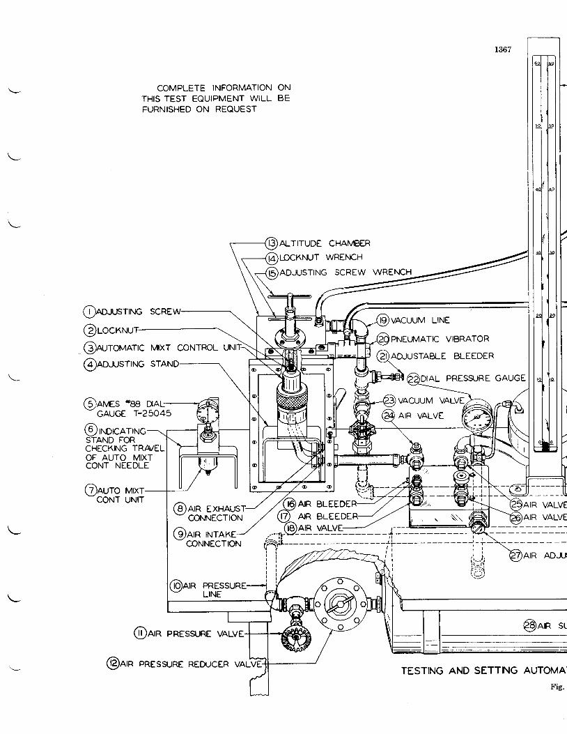
COMPLETE INFORMATIONTHIS TEST EQUIPMENT WILLFURNISHED ON REQUEST
ONB E
Oea.rcrrnrc scRE
@roc@n-,rorraarc Mrxr coNTRoL
@ar,aes oee DaL--GAUGE I-25O45
@'localNoSTAND FOR
@ao..usrrr.rc
Cauro urxr-CONT UNIT
CHECKING TRA/ELOF AUTO MIXTCONT NEEDLE
ALTITUDE CHAMBER
WREI.ICH
TING SCREW WREN|CH
AIR BLEEDEAIR BLEEDE
AIR EXHAUSTCONNECTION
@nrn TNTAKE@NNECTION
@arn PREssuRE
@nrn PRESSURE vALVE
VALVE
VALVE
@nrn sr
AND SETTNG AUTOMA'
Fig.
VACUUM LINE
PNEIA4ATIC VIBRATOR
AD.JUSTABLE BLEEDER
DIAL PRESS.JRE GAUGE
@arn PRESsuRE REDucERTESTING
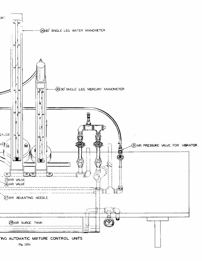
,36;
------@oo' srxrcle LEG wATER MANoMETER
AO,SIruCUE LEG MERCURY MANOMETER
@arn ADJJsTNG NEEDLE
AIR PRESSURE VALVE FOR VIBRATG
i$g1ti.$ara vALVE
$are vALVE
@arn suRGE rANK
rNG AUTOIUATIC MIXTURE CONTROL UNITS
1Il
Fig. 1334
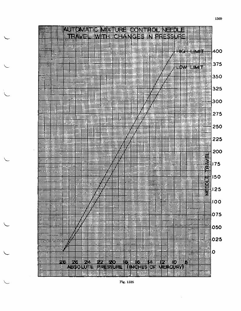
1369
375
50
32s
oo
275
250
225
200
75
. r50
t25
oo
75
o50
.o25
.o
Fis. 1335
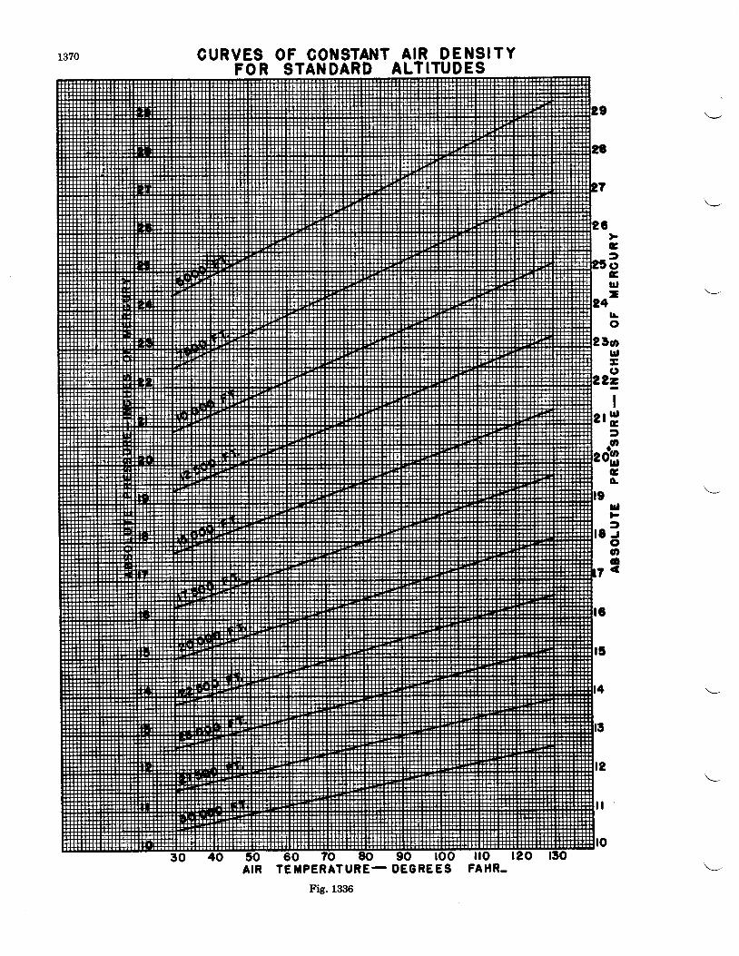
CURVES OF CONSTAI{TFOR STANDARD
A I R D E N S I T YALTITUDES
G
raGlr,-
0l!o
5olr,ao
?=
IrH
I
:2- g
Go'
ulFI
t - roo,o
7 <
TE]IPERATURE- DEGREES FAHR-
Fig. 1336
A I R
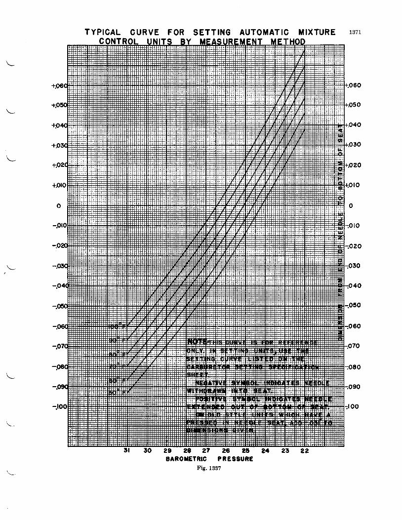
TYPICAL CURVE FOR SETTING AUTOMATIC MIXTUREc
2 9 2 8 2 7 2 0 2 t 2 aBAROTETRIC PRESSURE
Fig. 1B3Z
1371
l o
o


![PRATT & WHITNEY GEARED TURBOFANTM ENGINE FAST …...GoAir selects Pratt & Whitney GTF™ engines to Power 72 Additional Airbus A320neo Family Aircraft [read more] Pratt & Whitney GTF™](https://img.dokumen.tips/doc/110x75/5e6914b9a9534232a97b1b4d/pratt-whitney-geared-turbofantm-engine-fast-goair-selects-pratt-.jpg)