Embed Size (px)
Citation preview

International Journal of Science and Research (IJSR) ISSN (Online): 2319-7064
Impact Factor (2012): 3.358
Volume 3 Issue 6, June 2014 www.ijsr.net
Licensed Under Creative Commons Attribution CC BY
Design, Development and Testing of an Impeller of Open Well Submersible Pump for Performance
Improvement
Pranit M. Patil1, Sangram S. Patil2, Dr. R. G. Todkar3
1P.G. Student, Design Engineering, A.D.C.E.T. Ashta
2B.E. Student, Mechanical Engineering Department, A.D.C.E.T. Ashta
3Professor, Mechanical Engineering Department, A.D.C.E.T, Ashta
Abstract: Water pump design is well facilitated by the modern development of Computational Fluid Dynamics (CFD). The key parameters in pump impeller design are inlet and outlet diameters, inlet and outlet blade angles. These parameters play very important role in deciding the pump performance in terms of pressure head and flow rate developed for given input power consumption. This research work is devoted to use theoretical analysis in combination with CFD concepts for determination of optimum value of blade angle for maximum pressure head and discharge for water pump. Keywords: Impeller Blade angle, open well submersible pump, Pump performance, CFD.
1. Introduction Centrifugal pumps are probably among the most often used machinery in industrial facilities as well as in common life. After being invented they passed long evolutionary development until they became accessible for various applications. Their physical principle is described centuries ago by Euler through a well known equation named after him called Euler's equation for turbo machinery. Many technical applications of centrifugal pumps cannot be fulfilled without proper analysis, especially regarding its output parameters i.e. head and discharge. In recent days farmers want better performance from their pump at minimum input power. There are many techniques to improve the performance of the centrifugal pump. Impeller trimming is a common practice performed by pump manufacturers and users when it is necessary to adjust the centrifugal pump head and flow for the actual requirements. The impeller trimming is not strictly similar to the initial pump because only a few parameters are modified, while all the others remain unchanged. The method of pump impeller trimming found good experimental confirmation despite some theoretical constraints [1]. The flow pattern and power number in a vessel depend on the impeller blade angle, number of blades, blade width, blade twist, blade thickness, pumping direction and interaction of flow with the vessel wall. The effect of impeller design on the flow pattern and mixing time for a set of axial flow impellers have been studied by varying various parameters for impeller geometry. A very good agreement has been observed between experimental and the predicted mixing time over a wide range of impellers [2]. The performance characteristics of the impellers and the deteriorations in performance can be studied by varying tip clearance using ceramic materials [3].Impellers with splitter
blades have been used in turbo machinery design for both pumps and compressors. Increase in the number of blades increases the head of the pump, however, it causes a decrease in efficiency due to the blockage effect of the blade thickness and friction. The impellers with splitter blades between two long blades can be used to avoid the serious clogging at the inlet of the impeller caused by more number of blades [4]. Artificial Neural Network (ANN) used to predict the effects of splitter blades in a semi-open impeller on centrifugal pump performance. The characteristics of this impeller were compared with those of impellers without splitter blades. The values of head, efficiency, and effective power were estimated in a semi-open impeller with splitter blades in ratio of 3/6 and 5/6 of the main blade length at the best efficiency point. as the splitter blade length increases; the flow rate and power increases, the efficiency decrease [5]. The Flow through centrifugal pump impeller is three dimensional and fully turbulence model. The complex internal flows in Centrifugal pump impellers can be well predicted through ANSYS-CFX [6]. The complexity of the flow in any turbo machine is due to the three dimensional blade geometry, turbulence, secondary flows, unsteadiness etc. The numerical solution of the discretized three-dimensional, incompressible Navier-Stokes equations over an unstructured grid is accomplished with CFD package Ansys-CFX [7]. This research work aims to improve the performance of centrifugal pump by varying inlet and outlet angles for maximum head and discharge. Analytical procedure for determination of optimum discharge and head supported by CFD has been used for design of a centrifugal pump impeller. Experimental investigation has also been carried out to validate the theoretical design of centrifugal pump having 3hp at 2800 rpm rating.
Paper ID: 02014844 2670
International Journal of Science and Research (IJSR) ISSN (Online): 2319-7064
Impact Factor (2012): 3.358
Volume 3 Issue 6, June 2014 www.ijsr.net
Licensed Under Creative Commons Attribution CC BY
Nomenclature d1- inlet diameter of impeller, mm β2-blade outlet angle, ° d2- outlet diameter of impeller, mm
H- head developed, m
B1-blade width at inlet, mm Q- discharge, Lit/sec B2- blade width at outlet, mm ηs- speed of the impeller, rpm β1-blade inlet angle, ° η-efficiency, %
2. Design of Impeller The pump unit selected for redesign has the following specifications 1. Inlet Diameter (d1) = 60 mm 2. Outlet Diameter (d2) = 148 mm 3. Head (H) = 22 m 4. Discharge (Q) = 4 lit/sec 5. Blade Inlet Angle (β1) = 25 °
6. Blade Outlet Angle (β2) = 27° 7. Power = 3 hp 8. Speed (ηs) = 2800 rpm Blade angles β1 and β2 have been selected as variable parameters to optimize head developed H and discharge Q. Head H is calculated [8] as
Discharge Q is calculated [8] as
The selected range for β1 and β2 are 40° to 55° in both cases to determine the head and discharge developed by the pump using analytical treatment. Table 1 provides the data generated for head H and discharge Q using equation I and II for different values of β1 and β2
Table 1: Values of head H and discharge Q for different
values of β1 and β2 β1 β2 H Q
40° 40° 28.53 6.55
50° 34.29 6.55 55° 36.56 6.55
45° 40° 23.98 8.58
50° 31.08 8.58 55° 33.88 8.58
50° 40° 20.35 9.87
50° 28.53 9.87 55° 31.75 9.87
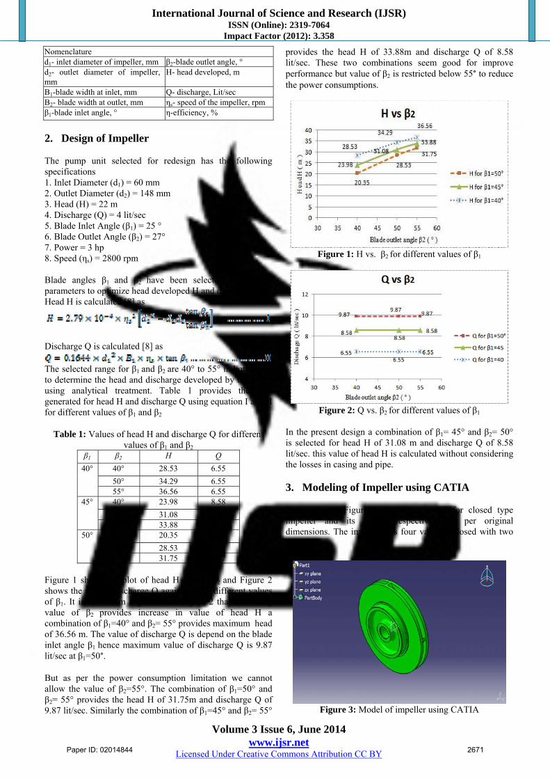
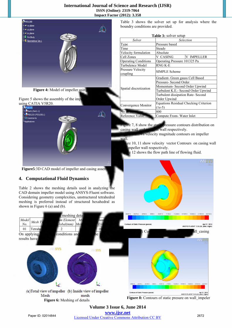
Figure 1 shows the plot of head H against β2 and Figure 2 shows the plot of discharge Q against β2 for different values of β1. It is seen from Figure 1 and Figure 2 that increasing value of β2 provides increase in value of head H a combination of β1=40° and β2= 55° provides maximum head of 36.56 m. The value of discharge Q is depend on the blade inlet angle β1 hence maximum value of discharge Q is 9.87 lit/sec at β1=50°. But as per the power consumption limitation we cannot allow the value of β2=55°. The combination of β1=50° and β2= 55° provides the head H of 31.75m and discharge Q of 9.87 lit/sec. Similarly the combination of β1=45° and β2= 55°
provides the head H of 33.88m and discharge Q of 8.58 lit/sec. These two combinations seem good for improve performance but value of β2 is restricted below 55° to reduce the power consumptions.
Figure 1: H vs. β2 for different values of β1
Figure 2: Q vs. β2 for different values of β1
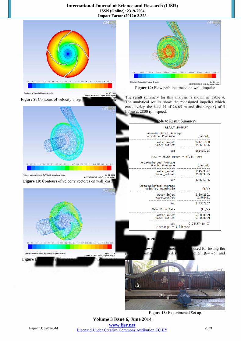
In the present design a combination of β1= 45° and β2= 50° is selected for head H of 31.08 m and discharge Q of 8.58 lit/sec. this value of head H is calculated without considering the losses in casing and pipe. 3. Modeling of Impeller using CATIA Figure 3 and Figure 4 show the model for closed type impeller and its casing respectively as per original dimensions. The impeller has four vanes enclosed with two end plates.
Figure 3: Model of impeller using CATIA
Paper ID: 02014844 2671
International Journal of Science and Research (IJSR) ISSN (Online): 2319-7064
Impact Factor (2012): 3.358
Volume 3 Issue 6, June 2014 www.ijsr.net
Licensed Under Creative Commons Attribution CC BY
Figure 4: Model of impeller using CATIA
Figure 5 shows the assembly of the impeller and casing using CATIA V5R20.
Figure5:3D CAD model of impeller and casing assembly
4. Computational Fluid Dynamics Table 2 shows the meshing details used in analyzing the CAD domain impeller model using ANSYS-Fluent software. Considering geometry complexities, unstructured tetrahedral meshing is preferred instead of structured hexahedral as shown in Figure 6 (a) and (b).
Table 2: meshing details Model
No. Mesh Type
Maximum Element Size Global(mm)
Minimum Mesh Quality
Number of Elements
01 Tetrahedral 2 0.30 1099413
On applying boundary conditions and solving the following results have generated.
Figure 6: Meshing of details
Table 3 shows the solver set up for analysis where the boundry conditions are provided.
Table 3: solver setup
Solver SelectionType Pressure based Time Steady Velocity formulation Absolute Cell Zones V_CASING V_IMPELLEROperating Conditions Operating Pressure 101325 PaTurbulence Model RNG K-E Pressure Velocity coupling
SIMPLE Scheme
Spatial discretization
Gradient- Green gauss Cell Based Pressure- Second Order Momentum- Second Order UpwindTurbulent K.E.- Second Order UpwindTurbulent dissipation Rate- Second Order Upwind
Convergence Monitor Equations Residual Checking Criterion (1e-5)
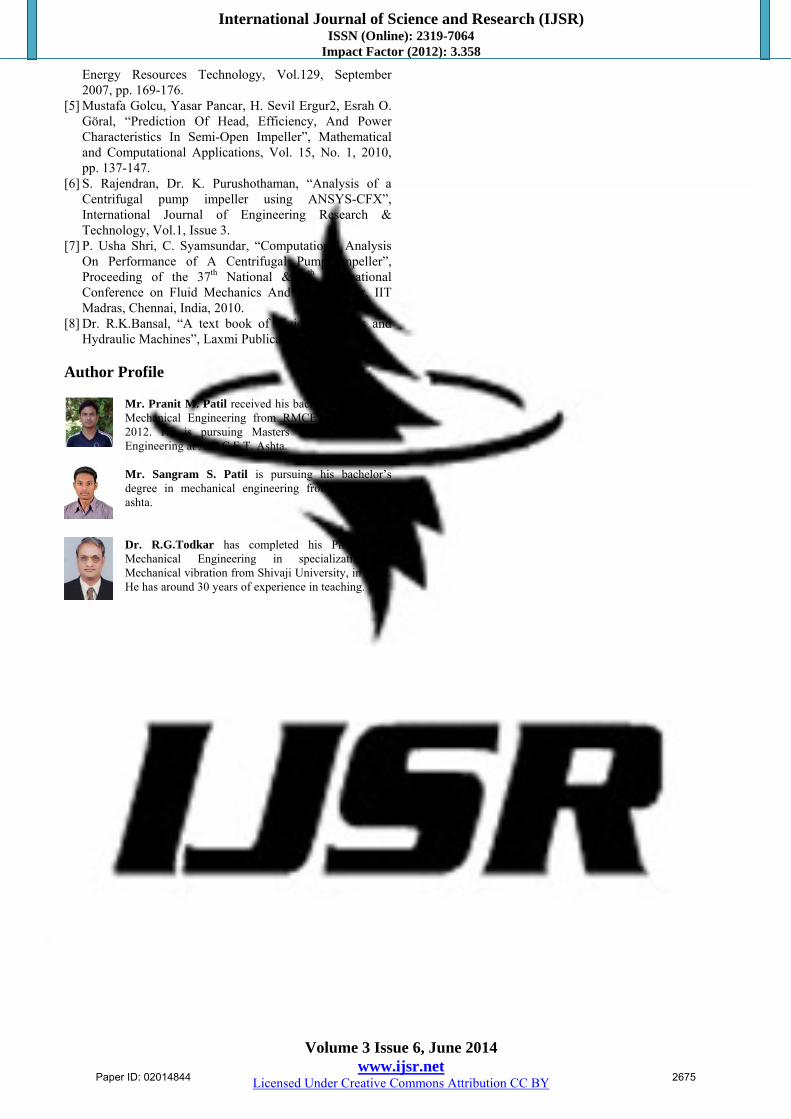
No of Iterations 800Reference Value Compute From- Water Inlet Figure 7, 8 show the static pressure contours distribution on casing wall and impeller wall respectively. Figure 9 shows velocity magnitude contours on impeller wall. Figure 10, 11 show velocity vector Contours on casing wall and impeller wall respectively. Figure 12 shows the flow path line of flowing fluid.
Figure 7: Contours of static presure on wall_casing
Figure 8: Contours of static presure on wall_impeler
Paper ID: 02014844 2672
International Journal of Science and Research (IJSR) ISSN (Online): 2319-7064
Impact Factor (2012): 3.358
Volume 3 Issue 6, June 2014 www.ijsr.net
Licensed Under Creative Commons Attribution CC BY
Figure 9: Contours of velocity magnitude on wall_impeler
Figure 10: Contours of velocity vectores on wall_casing
Figure 11: Contours of velocity vectores on wall_impeler
Figure 12: Flow pathline traced on wall_impeler
The result summery for this analysis is shown in Table 4. The analytical results show the redesigned impeller which can develop the head H of 26.65 m and discharge Q of 5 lit/sec at 2800 rpm speed.
Table 4: Result Summery
5. Experimental Set-up Figure 13 shows the experimental set up used for testing the pump performance with redesigned impeller (β1= 45° and β2= 50° )
Figure 13: Experimental Set up
Paper ID: 02014844 2673

International Journal of Science and Research (IJSR) ISSN (Online): 2319-7064
Impact Factor (2012): 3.358
Volume 3 Issue 6, June 2014 www.ijsr.net
Licensed Under Creative Commons Attribution CC BY
In Figure 13, 1. Pump set up using designed impeller 2. Underground Water tank 3. Flow sensor for head measurement 4. Discharge pipe. Figure 14 shows the control pannel for the experimental setup.
Figure 14: Digital Display board for experimental set up
1. Voltage, Current measurement meter 2. Slip measurement meter 3. Flow measurement meter
6. Experimental Results and Discussion Table 5 and Figure 15 show the comparison of the results obtained using theoretical results, CFD results and experimental results.
Table 5: Comparison of results
Particulars Theoretical
Results Analytical
Results Experimental
Results Discharge Q
(lit/sec) 8.58 lit/sec 5 lit/sec
4.06 lit/sec
Head H (m) 31.08 m 26.65 m 24.44 m
Figure 15: Graphical presentation of results
It is seen that the comparative results shows decreasing trends for head H and discharge Q developed by the redesigned impeller. It is the effect of fluid friction between casing and impeller and pipe.
7. Conclusion A centrifugal pump impeller is modeled and analyzed for optimizing the performance for the rating of 3 hp at 2800 rpm using theoretical analysis and CFD analysis. The redesigned pump is tested using standard test setup. The results obtained were compared for the respective trends. It is seen that the theoretical results show higher values when compared with experimental values. This is the effect of neglecting friction in theoretical analysis. There can be 10 % reduction in theoretical result of head due to the friction in casing and bents in pipe. Using experimental results it is seen that for the same input rating by changing the impeller inlet blade angles from 25° to 45° and outlet angle from 27° to 50° the head (H) developed is increased for 22 meters to 24.44 meters and discharge (Q) is increased for 4 lit/sec to 4.06 lit/sec. This is concluded that the CFD analysis can well predict the pump performance in design state. The authors are thank full to M/S. Torna Pumps, Kirloskarwadi, Sangli, Maharashtra for providing the problem for redesign of impeller and the cooperation extended for manufacturing, testing of redesigned impeller. 8. Future Scope The design of an open well submersible pump is improved by varying inlet and outlet blade angle to improve the pump performance. The results obtained clearly demonstrate the achievement of the objectives as indicated above. This work can be extended in future with following aspects for further research. 1. Changing Material: There is major scope to change the
material of pump, so that the losses of the pump will be reduces.
2. Skew cut: Skew cut one of the modern technique used for improving head. In this technique the backward vane profile cuts or trims at the periphery.
3. Coating to components: To reduce erosion–corrosion effects the coating technology is widely implement in the pump industries.
Reference [1] Mario Savar, Hrvoje Kozmar, Igor Sutlovic, “Improving
centrifugal pump efficiency by impeller trimming”, Elsevier, Desalination249, 2009,pp. 654-659.
[2] T. Kumaresan, Jyeshtharaj B. Joshi, “Effect of impeller design on the flow pattern and mixing in stirred tanks” , Elsevier, Chemical Engineering Journal 115, 2006, pp-(2006) 173–193.
[3] Tahsin Engin, Mesut Gur, Reinhard Scholz, “Effects of tip clearance and impeller geometry on the performance of semi-open ceramic centrifugal fan impellers at elevated temperatures”, Elsevier, Experimental Thermal and Fluid Science 30, 2006, pp- 565–577.
[4] M. Golcu, N. Usta, Y. Pancer, “Effects of Splitter Blades on Deep Well Pump Performance”, ASME, Journal of
Paper ID: 02014844 2674
International Journal of Science and Research (IJSR) ISSN (Online): 2319-7064
Impact Factor (2012): 3.358
Volume 3 Issue 6, June 2014 www.ijsr.net
Licensed Under Creative Commons Attribution CC BY
Energy Resources Technology, Vol.129, September 2007, pp. 169-176.
[5] Mustafa Golcu, Yasar Pancar, H. Sevil Ergur2, Esrah O. Göral, “Prediction Of Head, Efficiency, And Power Characteristics In Semi-Open Impeller”, Mathematical and Computational Applications, Vol. 15, No. 1, 2010, pp. 137-147.
[6] S. Rajendran, Dr. K. Purushothaman, “Analysis of a Centrifugal pump impeller using ANSYS-CFX”, International Journal of Engineering Research & Technology, Vol.1, Issue 3.
[7] P. Usha Shri, C. Syamsundar, “Computational Analysis On Performance of A Centrifugal Pump Impeller”, Proceeding of the 37th National & 4th International Conference on Fluid Mechanics And Fluid Power, IIT Madras, Chennai, India, 2010.
[8] Dr. R.K.Bansal, “A text book of Fluid mechanics and Hydraulic Machines”, Laxmi Publications(P) Ltd.
Author Profile
Mr. Pranit M. Patil received his bachelor’s degree in Mechanical Engineering from RMCET, Devrukh in 2012. He is pursuing Masters degree in Design Engineering at A.D.C.E.T. Ashta. Mr. Sangram S. Patil is pursuing his bachelor’s degree in mechanical engineering from A.D.C.E.T. ashta.
Dr. R.G.Todkar has completed his Ph.D. from Mechanical Engineering in specialization of Mechanical vibration from Shivaji University, in 2012. He has around 30 years of experience in teaching.
Paper ID: 02014844 2675


![[XLS] · Web viewPALAN JIGAR HITEN PATAT POOJA PATHAK AAKASH JAISHANKAR PATIL DIPESH ANIL PATIL ANUSHREE YASHWANT PATIL PRAFULLA MACHHINDRANATH PATIL TEJASVI CHANDRAKANT PAWAR ANUSHKA](https://img.dokumen.tips/doc/110x75/5b057d117f8b9aba168e8ae2/xls-viewpalan-jigar-hiten-patat-pooja-pathak-aakash-jaishankar-patil-dipesh-anil.jpg)