Embed Size (px)
Citation preview
Practical modeling of deep excavations
ZSoil Course 2018

FE mesh
This example concerns modeling of a deep excavation protected by diaphragm wall an then by a construction of foundation raft strengthened by bored piles.

48.0
36.0
0.8
Diaphragm wall
Top view
Dimension of the excavation is 48 m by 36 m in horizontal cross section.
2.0 1.2
2.0
1.2

2.7 m-5 m
10 kN/m2
20.0
0.8 m
1.0 m
7.5 m
plate
2.7 m
2.7 m
Engineering draft
Excavation is protected by 0.8 m thick concrete wall and will be performed in five steps up to level -11.5 m. Ground water table is at level -5.0 m. One meter thick plate is strengthen by ten meters long bored piles. Outside the excavation surface load of magnitude 10 kN/m2 is applied.
1st stage
Diaphragm wall
2nd stage
3rd stage
4th stage
5th stage
1.7 m
1.7 m
Strut
0.0 m- 1.7 m
- 3.4 m
- 6.1 m -5.6 m
- 8.8 m
- 12.5 m- 11.5 m
- 7.8 m

2.7 m-5 m
20.0
0.8 m
1.0 m
7.5 mplate
2.7 m
2.7 m
Slabs – thickness 30 cm
Engineering draft
Diaphragm wall
Slab -2
1.7 m
1.7 m
Slab -1
Slab 0- 3.4 m
- 6.1 m
- 8.8 m
- 12.5 m- 11.5 m
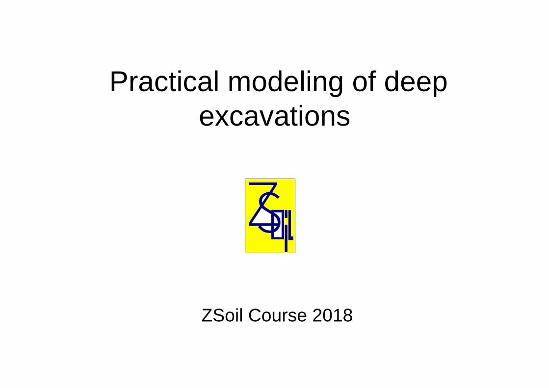
Top view (sketch)
3.0 6.0 6.0 5.23.4
Anchors (every 3.0 m
Anchors (every 3.0)
Nails (every 1.5 m)
Nails (every 1.5 m)
Struts
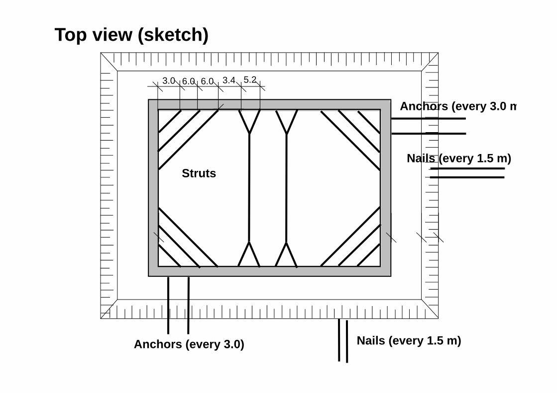
Piles
Mesh tying and Nodal linksconnection of nonconforming meshes
Continuum 3D
Interface elementsbetween diaphragm walls and soil
Model components
Thick shells
Thin shells

Solid boundary conditions
Pressure boundary conditions
Seepage elements
Pressure head
Boundary conditions
Box shaped solid boundary conditions and pressure boundary conditions for deformation and flow analysis have to be defined.

Loads Surface load 10 kN/m2
Nodal loads
Surface load outside of excavation zone is applied to the soil and surface. Nodal loads are applied to foundation plate.
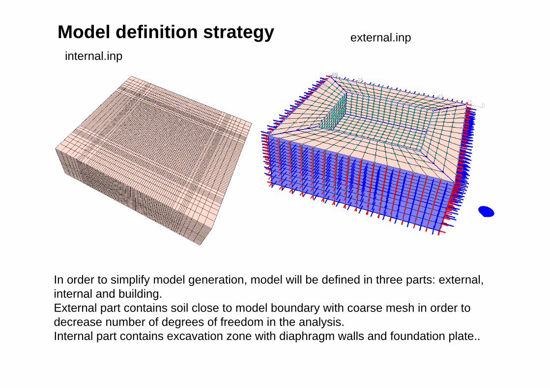
external.inpinternal.inp
Model definition strategy
In order to simplify model generation, model will be defined in three parts: external, internal and building. External part contains soil close to model boundary with coarse mesh in order to decrease number of degrees of freedom in the analysis. Internal part contains excavation zone with diaphragm walls and foundation plate..

1. In Preselection screen select : - Analysis type: 3D- Problem type: Deformation + Flow
Run ZSoil
Project preselection dialog box appears automatically when Zsoil Menu is started or for option File/New.
Preselection can be changed in ZSoil Menu or/and in ZSoil Preprocessor:

Import data settings
Definition of the material properties, load and existence functions and drivers will be skipped in this tutorial.
All these settings will be imported from INP file.
Open file StartData.inp

Existence functions (for steady state analysis) The sequence of excavation/construction stages is controlled by the existence functions, which are defined according to the sequence of events specified in the table below.
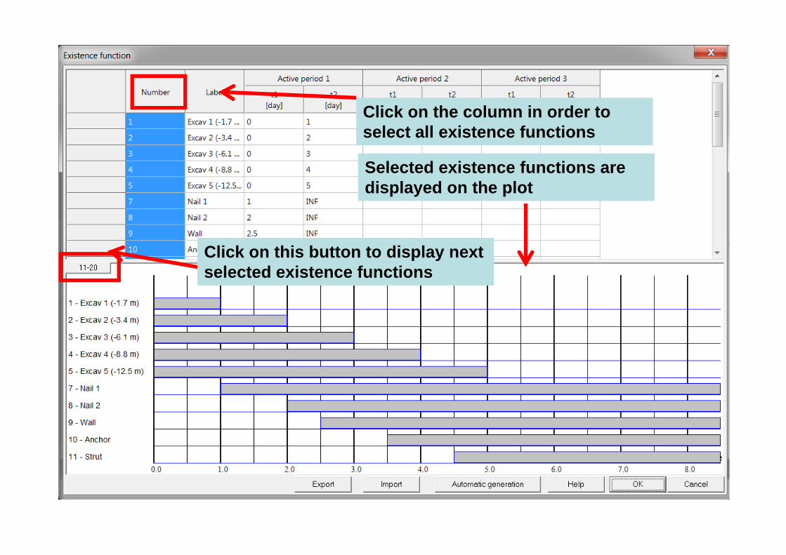
Click on the column in order to select all existence functions
Selected existence functions are displayed on the plot
Click on this button to display next selected existence functions

Existence functions
Click on this button to return to previously displayed existence functions

Load functions
The load time function associated with the surface load

Load functions

Materials

Imported data (materials, drivers, existence and load functions) will be used during geometry definition of all parts of the model. Lets save current stage into 2 files. Under ZSoil Menu choose File\Save As
1. Save as Internal.inp2. Save as external.inp
3. Run Preprocessing
Last saved file is external.inp so data for this part of the model will generated in the Preprocessing.
Saving files for all parts

Definition of external part - overview
1. Lines 2. Continuum 2D subdomain with virtual mesh
3. Extrude 2D subdomains to 3D subdomains
4. Delete one internal subdomain

-75 -45 45 75
-69
-39
39
69
Definition of external part
To speedup drawing of the model (especially in 3D) create construction lines using the toolbar, or top menu Settings/Construction lines.
Create construction lines

Create construction lines
Delete all(clik on position column in order to select all elements and press Delete button)
Add characteristic X coordinates:-75, -45, 45, 75
Delete all Add characteristic Y coordinate: 0
Delete all Add characteristic Z coordinates:-69, -39, 39, 69

Create two rectangles
1. Draw an external rectangle2. Draw an internal rectangle
Create lines
3. Turn off Continue
4. Draw four remaining segments lines connecting internal rectangle with external one
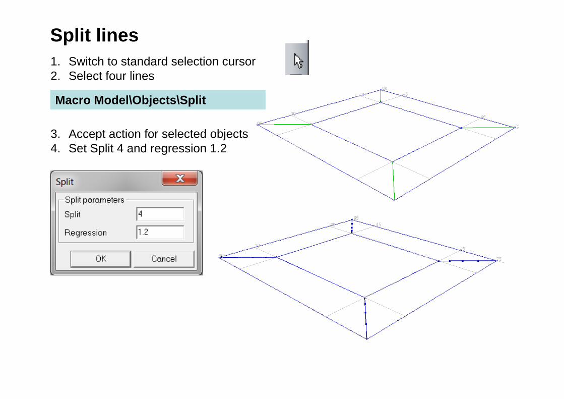
Split lines
Macro Model\Objects\Split
1. Switch to standard selection cursor2. Select four lines
3. Accept action for selected objects4. Set Split 4 and regression 1.2
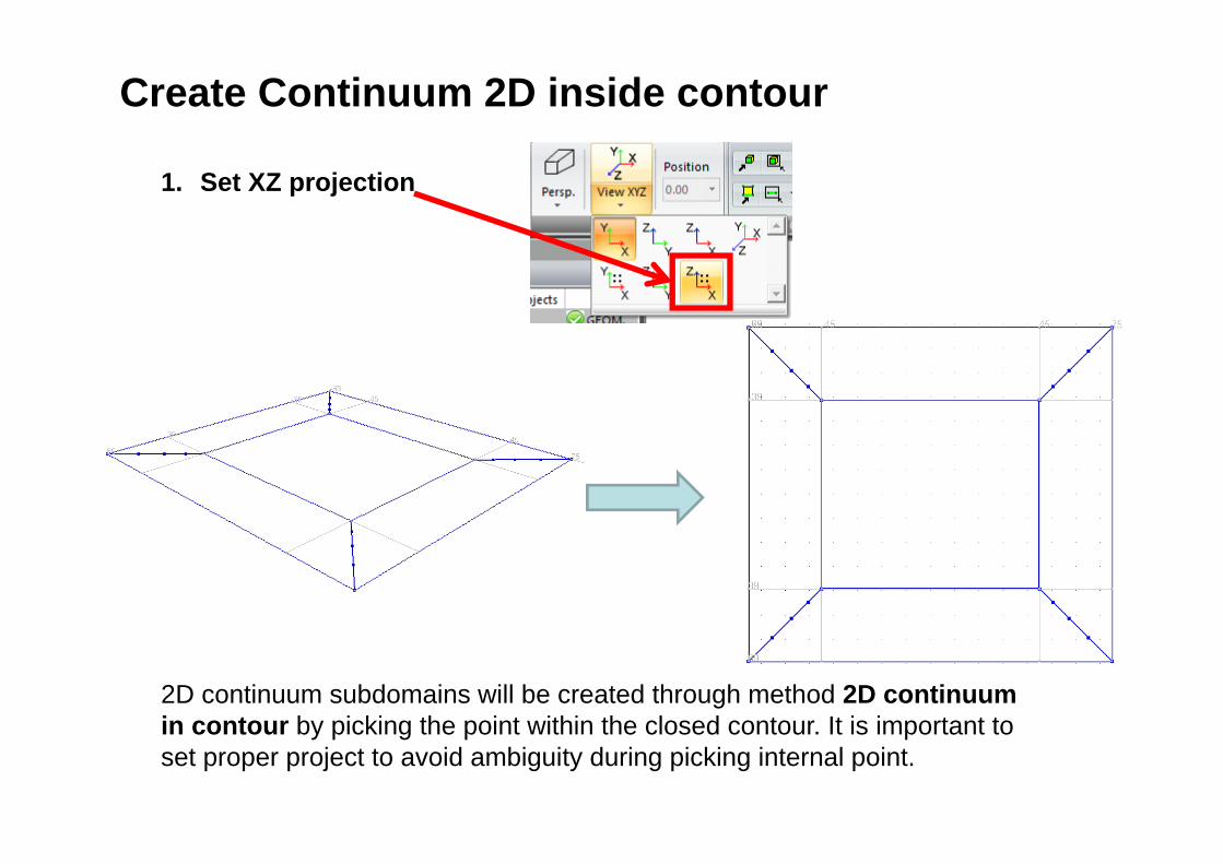
1. Set XZ projection
Create Continuum 2D inside contour
2D continuum subdomains will be created through method 2D continuum in contour by picking the point within the closed contour. It is important to set proper project to avoid ambiguity during picking internal point.

1. Macro Model\Subdomain\ 2D Continuum inside contour
2. Pick 5 times to create 5 subdomains
Create Continuum 2D inside contour

Create virtual mesh1. Macro Model\Subdomain\ Create virtual mesh2. Pick internal Subdomain3. Set Split 10 for Edge 1-2 and for edge 1-44. Press button Create virtual mesh
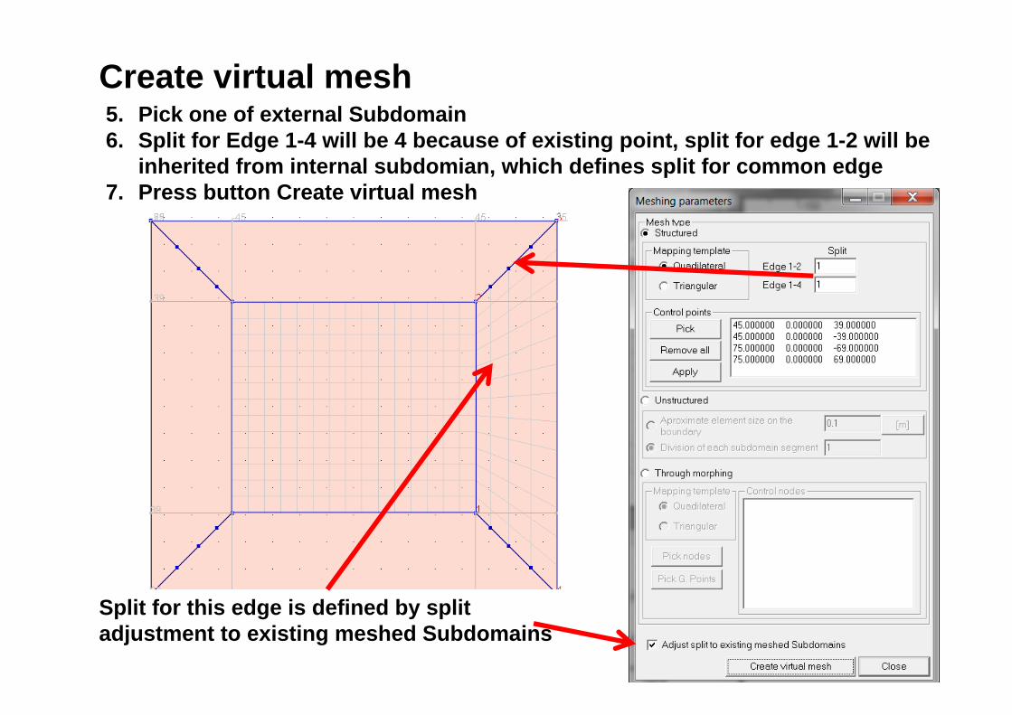
Split for this edge is defined by split adjustment to existing meshed Subdomains
Create virtual mesh5. Pick one of external Subdomain6. Split for Edge 1-4 will be 4 because of existing point, split for edge 1-2 will be
inherited from internal subdomian, which defines split for common edge7. Press button Create virtual mesh

Split for both edges is defined by split adjustment to existing meshed Subdomains
Create virtual mesh8. Pick next external Subdomain9. Press button Create virtual mesh10.Repeat steps for next two ramaining subdomains

Create Continuum 3D by faces extrusion1. Set 3D view
2. Select faces in zoom box

Create Continuum 3D by faces extrusion3. Macro Model\Subdomain\ 3D Continuum\ 3D Continuum by Face(s)
extrusion

4. Set vector
5. Check multiple extrusion
6. Define parameters for multiple extrusion and press OK
7. Apply
Create Continuum 3D by faces extrusion

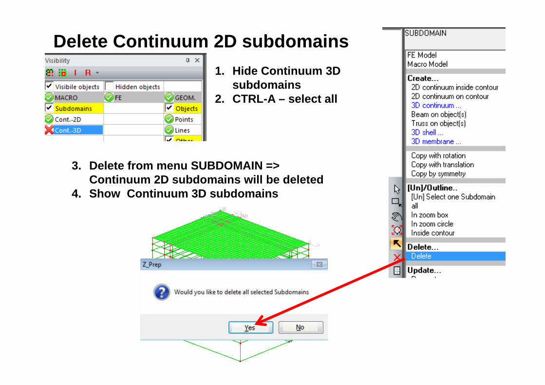
3. Delete from menu SUBDOMAIN => Continuum 2D subdomains will be deleted
4. Show Continuum 3D subdomains
Delete Continuum 2D subdomains1. Hide Continuum 3D
subdomains2. CTRL-A – select all

Remove top Continuum 3D subdomain1. Macro Model\Subdomain\ Delete or icon Delete2. Pick Subdomain

Seepage1. Set orthogonal camera2. Set XZ view3. Set cursor in Select faces in zoom box mode4. Select external faces (4 x zoom box)5. Macro Model\ Seepage\On Subdomain face(s)

Pressure BC1. Macro Model\ Pressure BC\Fluid head on selected faces

Unselect all
Select All (CTRL-A) Macro Model\Subdomain\Virtual -> Real mesh
Create Real mesh

Creat group of faces for Mortar interface1. Select faces in box defined by 2 nodes
2. FE Model\ Mesh Tying\Group of faces3. Set name „External”
1
2

FE Model\Initial Conditions\Initial stresses\On bounding boxCreate Initial Stresses

Initial stresses

FE Model\Boundary Conditions\Solid BC On box
FILE\Save model and return to Main Menuwith saving changes
Create Solid BC
Definition of external part is completed

In ZSoil menu Open – Internal.inpRun Preprocessing
Create construction lines
Definition of internal part
-24-31 0
-25
0
-20.8
-18
-24.8
-26.8
-18.8
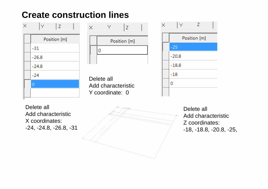
Delete all Add characteristic X coordinates:-24, -24.8, -26.8, -31
Delete all Add characteristic Y coordinate: 0
Delete all Add characteristic Z coordinates:-18, -18.8, -20.8, -25,
Create construction lines

Create rectangles Draw 4 rectangles along X direction
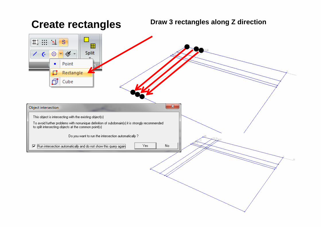
Create rectangles Draw 3 rectangles along Z direction

2. Macro Model\Subdomain\ 2D Continuum inside contour
3. Pick 16 times to create 16 subdomains
1. Set XZ projection Create Continuum 2D inside contour

Create virtual mesh1. Macro Model\Subdomain\ Create virtual mesh2. Pick Subdomain3. Set Split 24 for Edge 1-2 and 18 for 1-4 4. Press button Create virtual mesh

Split 24
Split 18
Split 1
Create virtual mesh
Split 2
Split 4
Split 4
Split 2Split 1
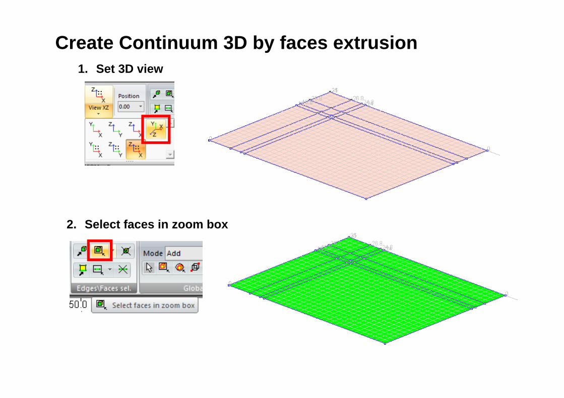
1. Set 3D view
2. Select faces in zoom box
Create Continuum 3D by faces extrusion

3. Macro Model\Subdomain\ 3D Continuum\ 3D Continuum by Face(s) extrusion
Create Continuum 3D by faces extrusion

4. Set vector
5. Check multiple extrusion
6. Define parameters for multiple extrusion and press OK
7. Apply
Create Continuum 3D by faces extrusion
3. Delete from menu SUBDOMAIN => Continuum 2D subdomains will be deleted
4. Show Continuum 3D subdomains
Delete Continuum 2D subdomains1. Hide Continuum 3D
subdomains2. CTRL-A – select all
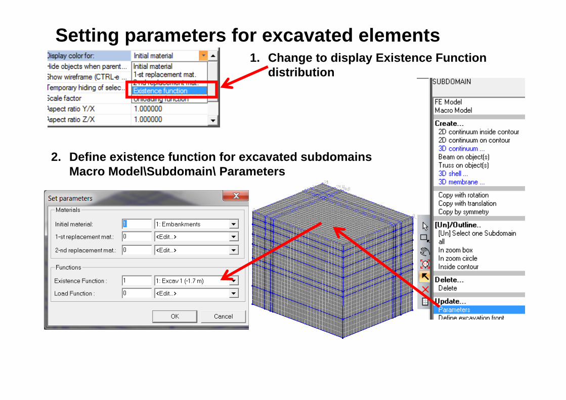
Setting parameters for excavated elements1. Change to display Existence Function
distribution
2. Define existence function for excavated subdomains Macro Model\Subdomain\ Parameters

Setting parameters for excavated elements
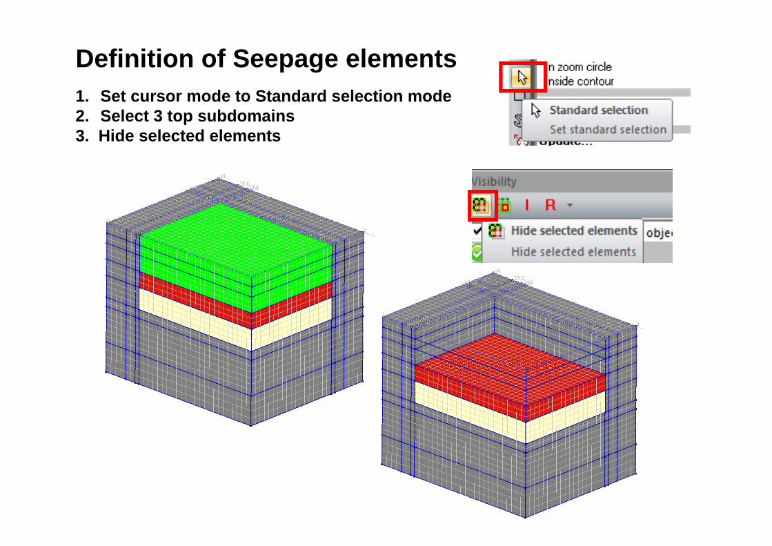
1. Set cursor mode to Standard selection mode2. Select 3 top subdomains3. Hide selected elements
Definition of Seepage elements

4. Macro Model\ Seepage\On Subdomain face(s)5. Pick top face
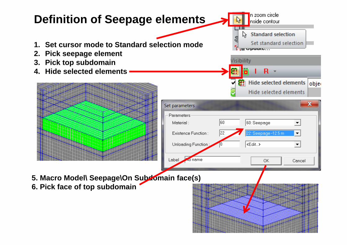
Definition of Seepage elements

1. Set cursor mode to Standard selection mode2. Pick seepage element3. Pick top subdomain4. Hide selected elements
Definition of Seepage elements
5. Macro Model\ Seepage\On Subdomain face(s)6. Pick face of top subdomain
1. Set cursor mode to Standard selection mode2. Pick seepage element3. Pick top subdomain4. Hide selected elements
Definition of Seepage elements
5. Macro Model\ Seepage\On Subdomain face(s)6. Pick face of top subdomain

Definition of supporting system for first two stages
0.85 m1st stage
2nd stage1.7 m
1.7 m
0.85 m
1.2 m
shotcrete
15°15°
nails

Update coordinates for a slope1. Set orthogonal camera2. Set XY view3. Unselect all elements4. Set selection in Zoom box mode5. Select nodes in zoom box

Update coordinates for a slope1. Macro Model\Points\Move Point
2. Unselect all elements3. Set selection in Zoom box mode4. Select nodes in zoom box5. Macro Model\Points\Move Point

Update coordinates for a slope1. Set orthogonal camera2. Set YZ view3. Unselect all elements4. Set selection in Zoom box mode5. Select nodes in zoom box

Update coordinates for a slope1. Macro Model\Points\Move Point
2. Unselect all elements3. Set selection in Zoom box mode4. Select nodes in zoom box5. Macro Model\Points\Move Point
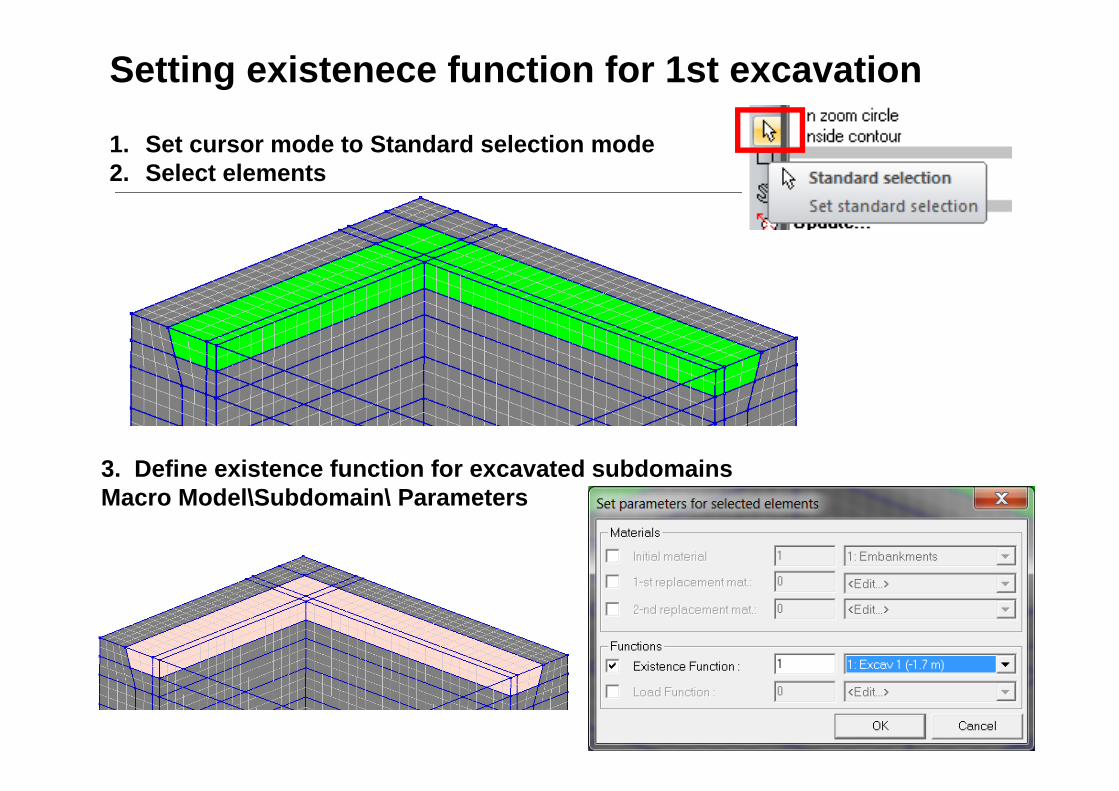
Setting existenece function for 1st excavation
1. Set cursor mode to Standard selection mode2. Select elements
3. Define existence function for excavated subdomains Macro Model\Subdomain\ Parameters

Setting existenece function for 2nd excavation
1. Hide slected elements2. Set cursor mode to Standard selection mode3. Select elements
3. Define existence function for excavated subdomains Macro Model\Subdomain\ Parameters

1. Hide selected elements 2. Set cursor mode to Faces selection mode3. Pick faces for first layer of shotcrete elements
Definition of elements for shotcrete
4. Macro Model\Subdomain\ 3D shell\3D shell on face(s)

1. Unselect all2. Set cursor mode to Faces selection mode3. Pick faces for second layer of shotcrete elements
Definition of elements for shotcrete
4. Macro Model\Subdomain\ 3D shell\3D shell on face(s)
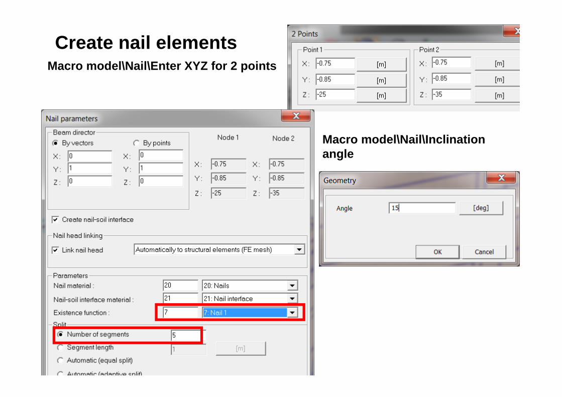
Create nail elementsMacro model\Nail\Enter XYZ for 2 points
Macro model\Nail\Inclination angle

Create nail elementsMacro Model\Nail\Copy with translation
Set length - Macro Model\Nail\Length
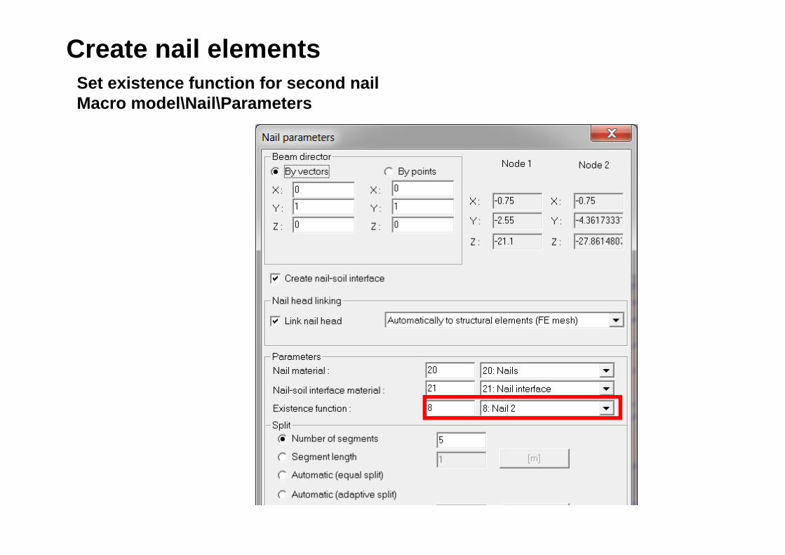
Create nail elementsSet existence function for second nail Macro model\Nail\Parameters

Select all nail elements - Macro Model\Nail\allMacro Model\Nail\Copy with translation
Create nail elements
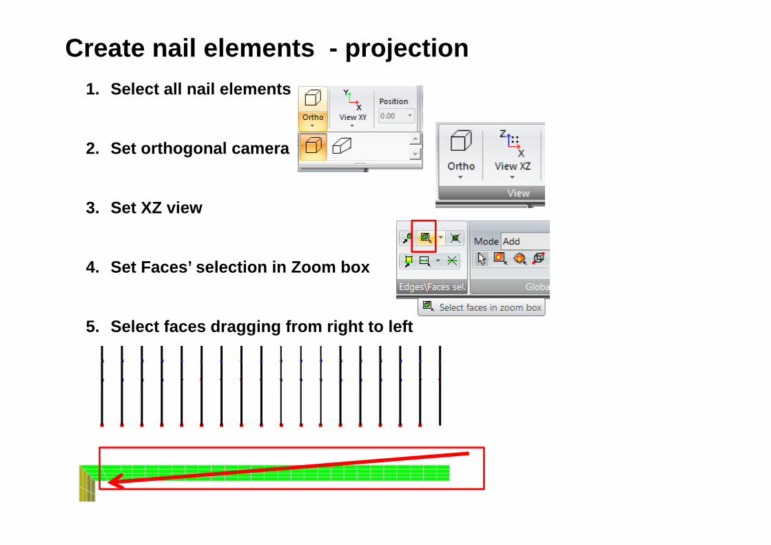
Create nail elements - projection1. Select all nail elements
2. Set orthogonal camera
3. Set XZ view
4. Set Faces’ selection in Zoom box
5. Select faces dragging from right to left

Macro Model\Nail\Shift by head proj. On faces in dir.
Set vector of projection in Z direction
Create nail elements - projection

Create nail elementsMacro model\Nail\Enter XYZ for 2 points
Macro model\Nail\Inclination angle

Create nail elementsMacro Model\Nail\Copy with translation
Set length - Macro Model\Nail\Length

Create nail elementsSet existence function for second nail Macro model\Nail\Parameters

Select 2 nail elements - Macro Model\Nail\all
Macro Model\Nail\Copy with translation
Create nail elements
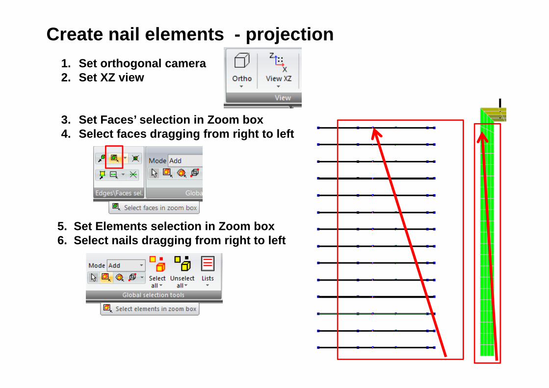
Create nail elements - projection1. Set orthogonal camera2. Set XZ view
3. Set Faces’ selection in Zoom box4. Select faces dragging from right to left
5. Set Elements selection in Zoom box6. Select nails dragging from right to left

Macro Model\Nail\Shift by head proj. On faces in dir. Set vector of projection in X direction
Create nail elements - projection
1 0 0

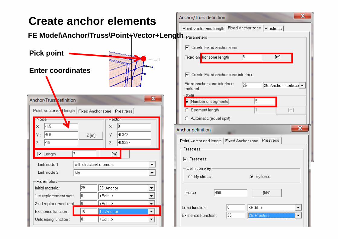
Create anchor elementsFE Model\Anchor/Truss\Point+Vector+Length
Pick point
Enter coordinates

Create anchor elementsFE Model\Anchor/Truss\Copy\Copy with translation
FE Model\Anchor/Truss\Scale
Create anchor elementsFE Model\Anchor/Truss\Point+Vector+Length
Pick point
Enter coordinates
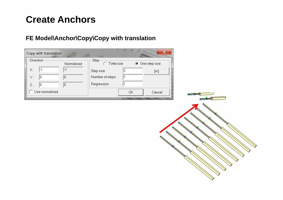
Create Anchors
FE Model\Anchor\Copy\Copy with translation

3.0 6.0 6.0 5.23.4
Struts
Create Struts

Create StrutsCreate points along X directionMacro Model\Point\Point

Create StrutsCreate points along Z directionMacro Model\Point\Point

Create StrutsFE Model\Anchor\ Between 2 nodes/points

Create StrutsFE Model\Anchor\ Between 2 nodes/points

Create slab - 01. Set cursor mode to
Standard selection mode2. Pick two top internal
subdomains3. Hide selected elements
4. Macro Model\Subdomain\3D Shell\3D Shell on faces
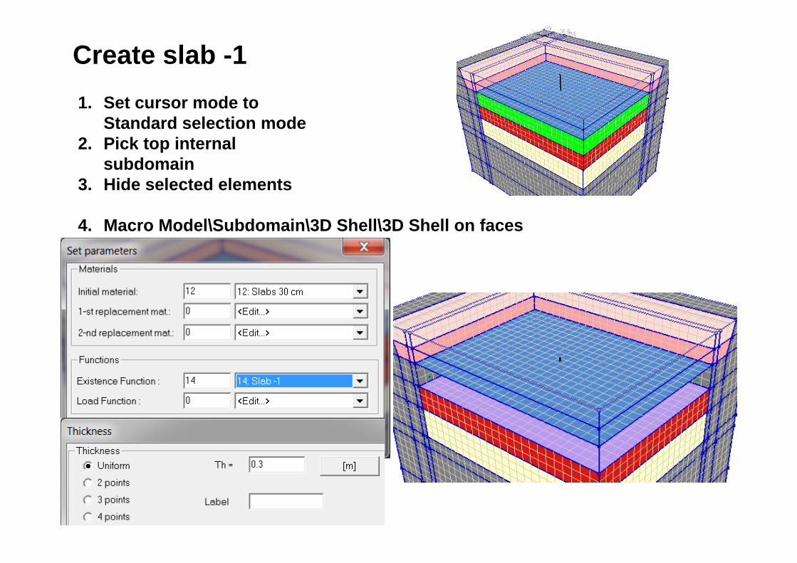
Create slab -11. Set cursor mode to
Standard selection mode2. Pick top internal
subdomain3. Hide selected elements
4. Macro Model\Subdomain\3D Shell\3D Shell on faces

Create slab -21. Set cursor mode to
Standard selection mode2. Pick top internal
subdomain3. Hide selected elements
4. Macro Model\Subdomain\3D Shell\3D Shell on faces
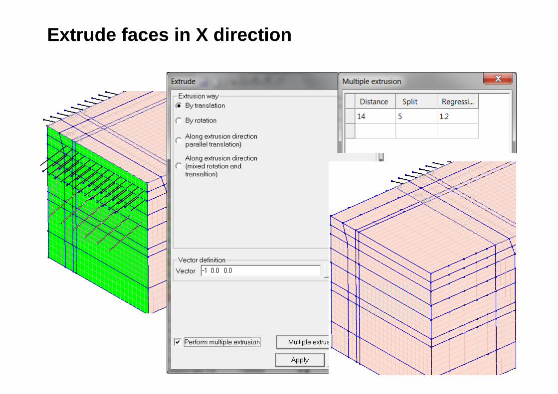
Extrude faces in X direction

Extrude faces in Z direction

Create Auxiliary planes
1
2
3
1
2
3

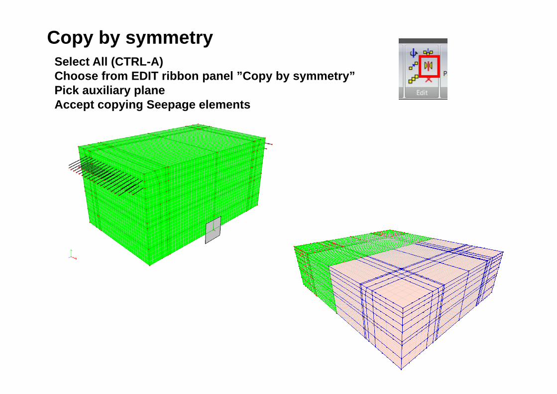
Copy by symmetrySelect All (CTRL-A) Choose from EDIT ribbon panel ”Copy by symmetry”Pick auxiliary planeAccept copying Seepage elements
Copy by symmetrySelect All (CTRL-A) Choose from EDIT ribbon panel ”Copy by symmetry”Pick auxiliary planeAccept copying Seepage elements

Unselect all
Create Real meshSelect All (CTRL-A) Macro Model\Subdomain\Virtual -> Real mesh

Create WallSet XY projectionSelect elements in Zoom box
Set XZ projectionSelect elements in Zoom box
Hide selected elements

Select in Zoom box corner elements and set parametersFE Model\Continuum 3D\ Parameters
Create Wall
Hide selected elements
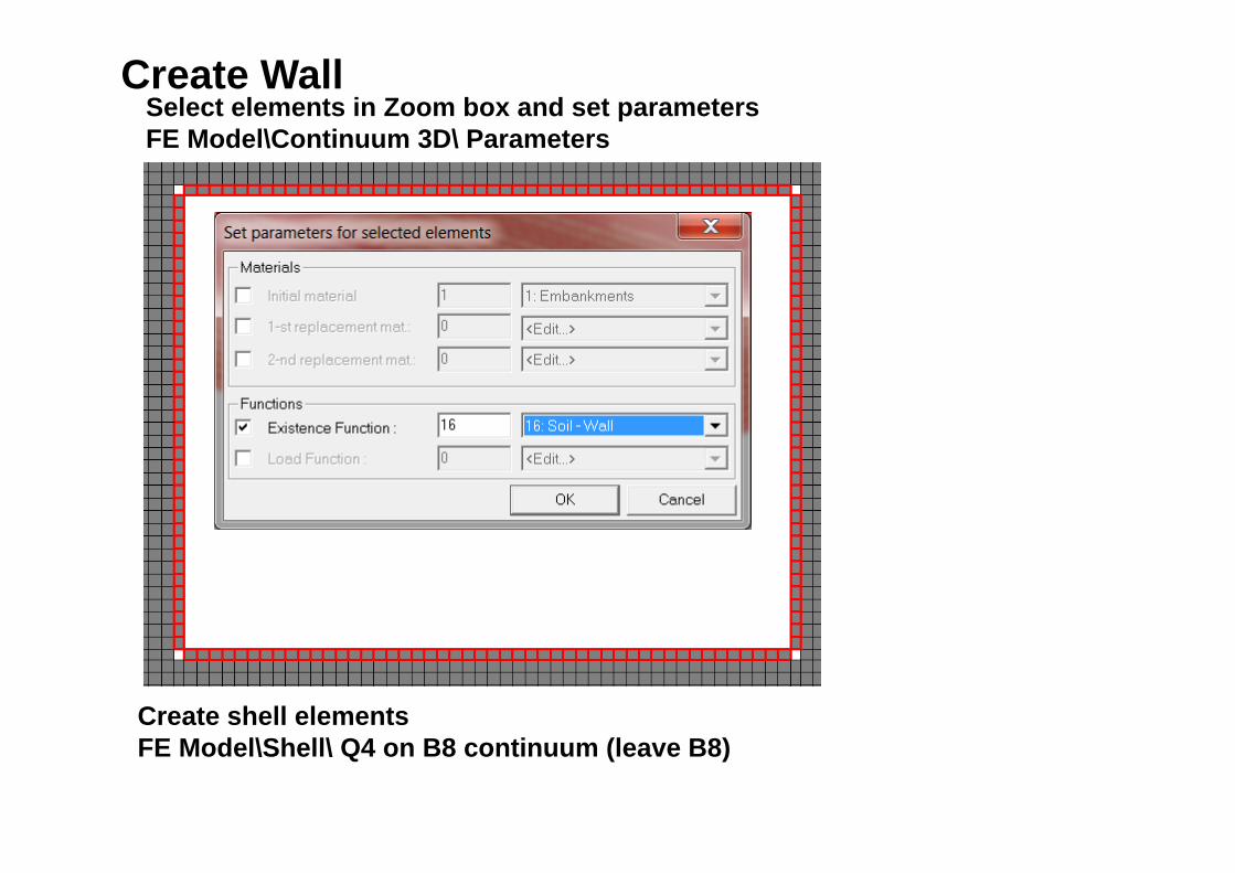
Select elements in Zoom box and set parametersFE Model\Continuum 3D\ Parameters
Create Wall
Create shell elementsFE Model\Shell\ Q4 on B8 continuum (leave B8)
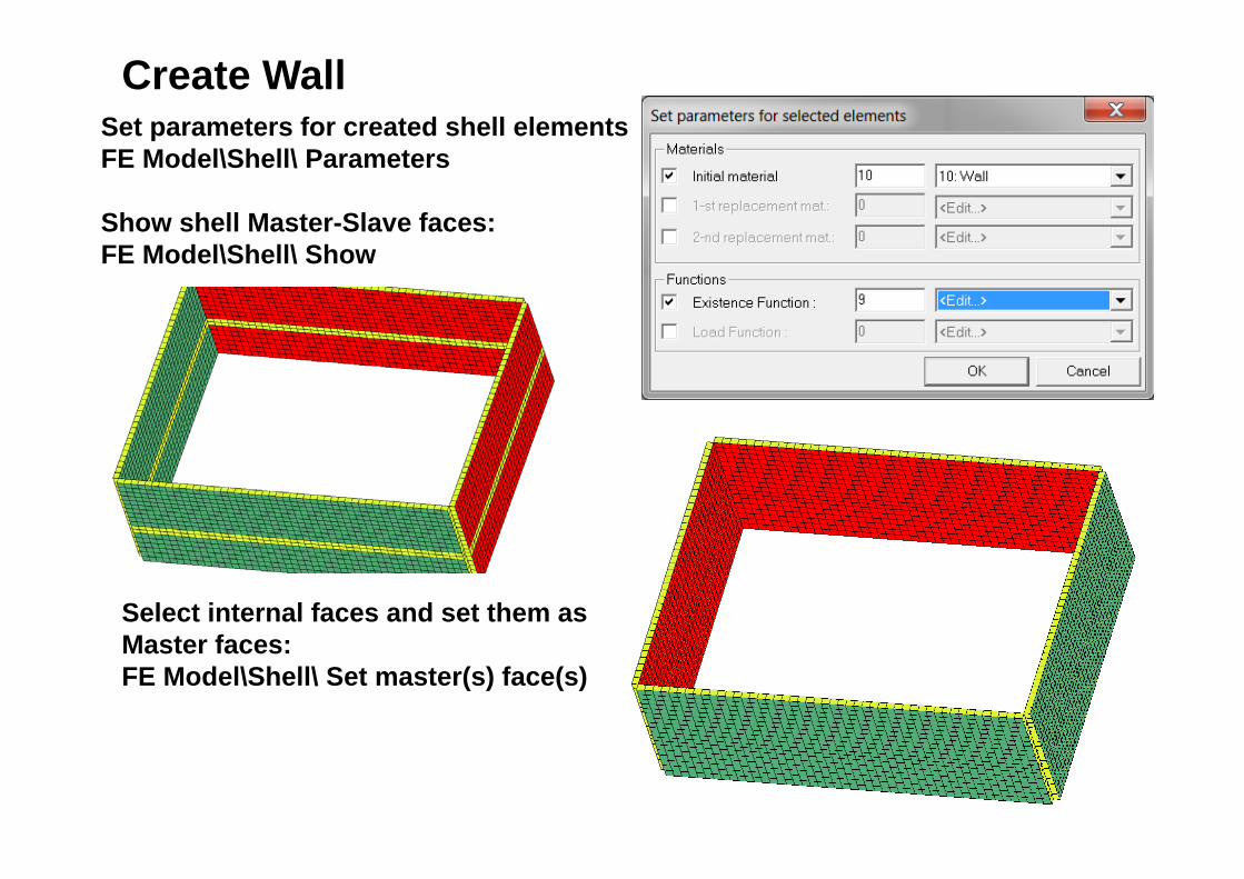
Create WallSet parameters for created shell elementsFE Model\Shell\ Parameters
Show shell Master-Slave faces:FE Model\Shell\ Show
Select internal faces and set them as Master faces:FE Model\Shell\ Set master(s) face(s)

Create Interface on the wall1. Restore hidden elements2. Unselect all 3. Select Continuum 3D elements with EF = 164. Select elements with EF = 17 and add to the list

Create Interface on the wall5. Show selected elements6. Set XZ view7. Select internal and external faces
in Zoom box

Create Interface on the wall8. FE Model\Interface\ On Continuum elem. Face(s)

Create Interface on the wall9. Unselect all faces10.Set XY view 11.Select top faces in Zoom Box12.FE Model\Interface\ On Continuum elem. Face(s)

Create bottom slab1. Restore hidden elements2. Show excavation/construction stages with time 5.5.
3. Select faces in box 2 nodes
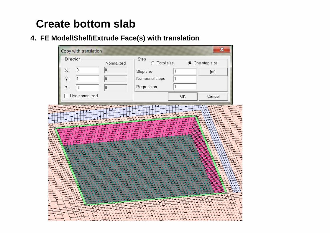
Create bottom slab4. FE Model\Shell\Extrude Face(s) with translation

Create bottom slab5. Select Shells with EF = 0 6. Set parameters for selected elements

Create bottom slab6. Check Master faces if they are at bottom of the slab

Create interface between bottom slab and soil1. Show selected elements2. Set XY projection 3. Select bottom faces4. FE Model\Interface\ On Continuum elem. Face(s)

Create auxiliary shell of Slave faces of the slab1. Set XY projection 2. Select top faces3. FE Model\Shell one layer\ On face(s)

Piles under bottom slab3 37 x 6 m
6 x 5 m

Piles under bottom slab1. Create piles by coordinatesMacro Model\Pile\Enter XYZ for two points

Copy pile in X directionMacro Model\Pile\Copy with translation
Piles under bottom slab

Piles under bottom slab3. Select all PilesMacro Model\Pile\all4. Copy pile in Z directionMacro Model\Pile\Copy with translation
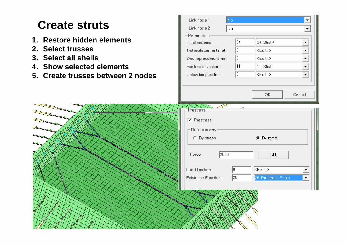
Create struts1. Restore hidden elements2. Select trusses3. Select all shells4. Show selected elements5. Create trusses between 2 nodes

-------------------------------------------------------------------------------Time : 5.00000E+00
-----------------------------------------------------------------------------------> 2 Stage : Solution of the Deformation State
Nonlinear solver: Quasi-Newton (BFGS) Linear solver : Direct (sparse)
ITER SQR_FORC RHS_FORC SQR_MOMT RHS_MOMT DEN_DEFO ENE_DEFO LHS status 1 1.470E+03 1.000E+00 1.639E+02 1.000E+00 1.000E+00 1.000E+00 MODIFIED
WARNING :Null pivot detected (equation eliminated)Null pivot detected at nodePossible reasons:1) floating contact/seepage elements2) relaxations defined in the two beam elements on same nodeThis instability has been removed by the code, however please correct the dataas the code speed is strongly affected by circumventing this effect
145 1 <DOF> < DISPL-UY>
Soil BC for Struts
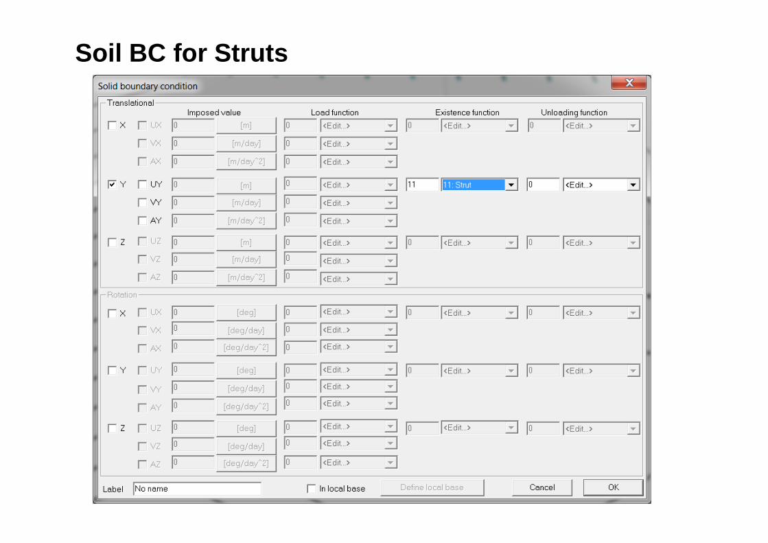
Soil BC for Struts

Definition of columns between slabs1. Create beam with coordinates

Definition of columns between slabs1. Set parameters
2. Copy with translation

3. Set Existence function

4. Copy selected beamsFE Model\Beam\Copy with translation

Create group of faces for Mesh tying1. Select external faces in Zoom box
2. FE Model\ Mesh Tying\Group of faces3. Set name ”Internal”

Check excavation stages
Save file in ZSoil menu =>File/Save
FILE\Save model and return to Main Menu with saving changes
Definition of internal part is completed

1. Open External.inp in Zsoil Menu2. Save as Wall3D.inp3. Run preprocessing4. File\Import geometrical model (*.inp)internal.inp
Merging defined parts
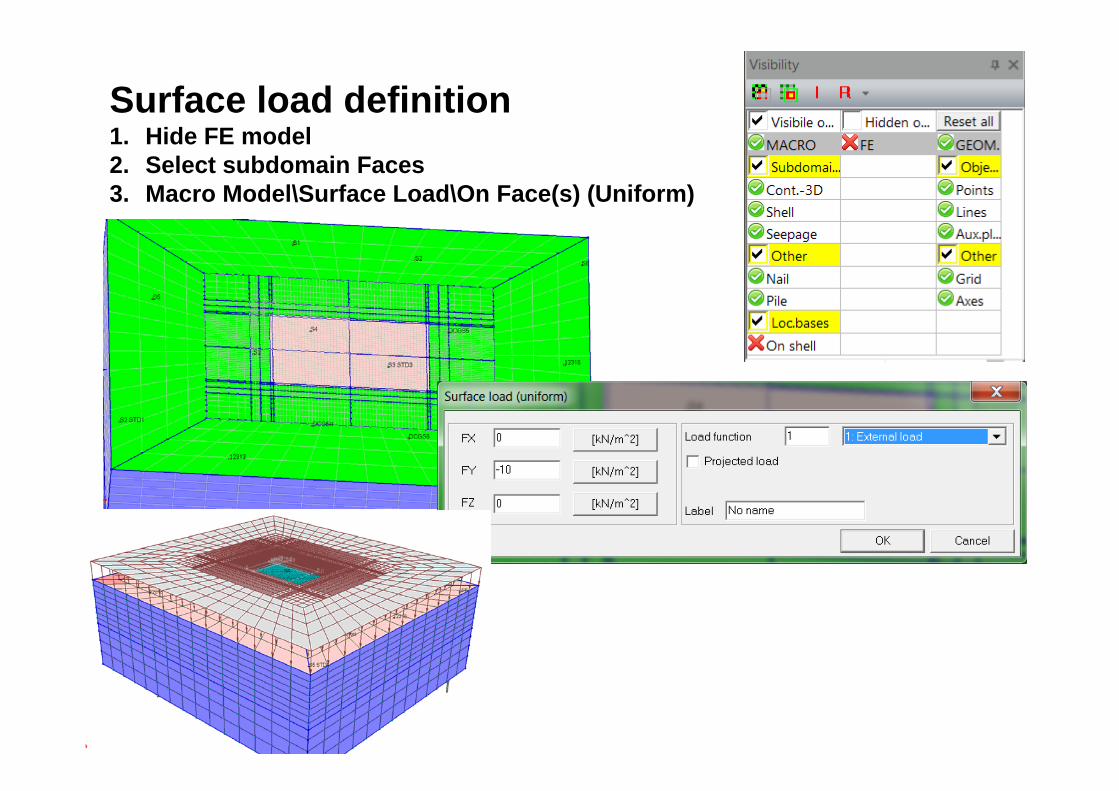
Surface load definition1. Hide FE model2. Select subdomain Faces3. Macro Model\Surface Load\On Face(s) (Uniform)
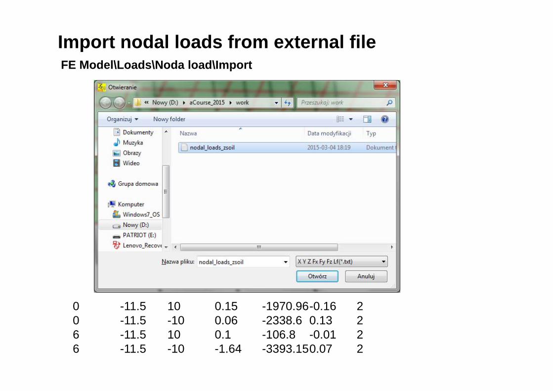
Import nodal loads from external file
0 -11.5 10 0.15 -1970.96-0.16 20 -11.5 -10 0.06 -2338.6 0.13 26 -11.5 10 0.1 -106.8 -0.01 26 -11.5 -10 -1.64 -3393.150.07 2
FE Model\Loads\Noda load\Import

Link nodes with nodal load with plate1. Select nodes with nodal load2. Select Shells one layer with material 50

Show selected elements in order to check what was selected
FE Model\Nodal link\ On node(s)
Link nodes with nodal load with plate

Link Shell nodes to the wall
1. Restore hidden elements2. Select all shells one layer3. Select nodes which belongs to selected shells4. Select all shells5. FE Model\Interface\Link selected shell node(s)

Create boreholes
Domain\Boreholes\Map material on visible elements
Domain\Boreholes\Import
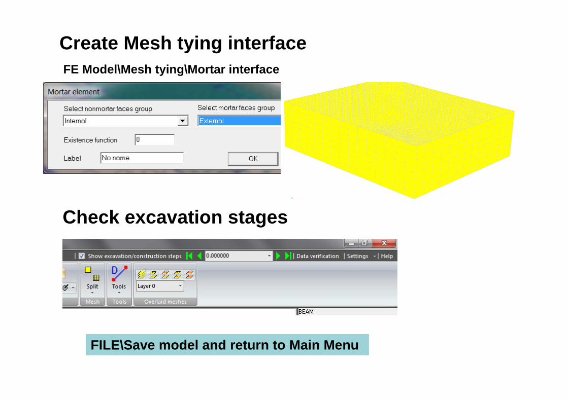
Create Mesh tying interface
Check excavation stages
FILE\Save model and return to Main Menu
FE Model\Mesh tying\Mortar interface