Embed Size (px)
Citation preview
WWW.PPI-ENGINEERING.COM
PP1214 - PURGE AND PRESSURISATION SYSTEMENHANCED CONTROLEFFICIENT PRESSURE MONITORING INTELLIGENT LEAKAGE COMPENSATION
WWW.PPI-ENGINEERING.COM
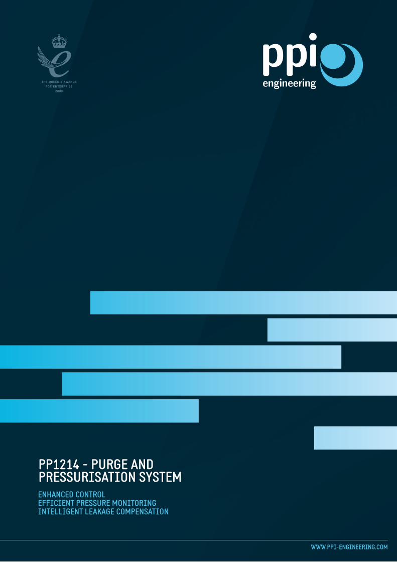
PPI ENGINEERING LTDPPI Engineering is an international engineering company specialising in the design, supply and support of rotating machines and associated equipment. We operate an ISO9001:2008 quality system and have an established reputation for technical excellence, quality and reliability. Our team of highly qualified engineers are drawn from the major UK electrical machine manufacturers, with extensive onshore and offshore, mechanical and electrical expertise.
PPI Engineering’s market leading Purge and Pressurisation safety device ensures the safe operation of electrical machines and enclosures within Zone 1/21 and 2/22 hazardous areas. The unique attributes of this system provides numerous advantages over its competitors.
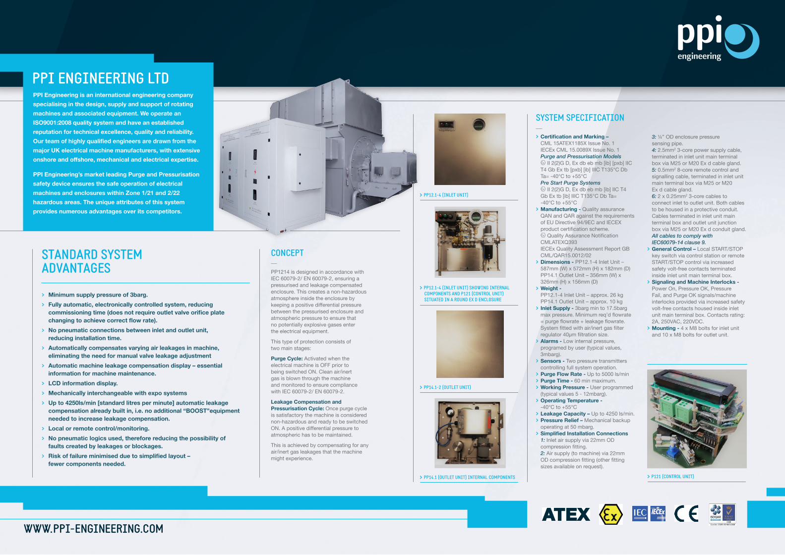
SYSTEM SPECIFICATION > Certification and Marking – CML 15ATEX1185X Issue No. 1 IECEx CML 15.0089X Issue No. 1 Purge and Pressurisation Models II 2(2)G D, Ex db eb mb [ib] [pxb] IIC T4 Gb Ex tb [pxb] [ib] IIIC T135°C Db Ta= -40°C to +55°C Pre Start Purge Systems II 2(2)G D, Ex db eb mb [ib] IIC T4 Gb Ex tb [ib] IIIC T135°C Db Ta= -40°C to +55°C > Manufacturing - Quality assurance QAN and QAR against the requirements of EU Directive 94/9EC and IECEX productcertificationscheme. QualityAssuranceNotification CMLATEXQ393 IECEx Quality Assessment Report GB CML/QAR15.0012/02 > Dimensions - PP12.1-4 Inlet Unit – 587mm (W) x 572mm (H) x 182mm (D) PP14.1 Outlet Unit – 356mm (W) x 326mm (H) x 156mm (D) > Weight - PP12.1-4 Inlet Unit – approx. 26 kg PP14.1 Outlet Unit – approx. 10 kg > Inlet Supply - 3barg min to 17.5barg maxpressure.Minimumreq’dflowrate =purgeflowrate+leakageflowrate. Systemfittedwithair/inertgasfilter regulator40μmfiltrationsize. > Alarms - Lowinternalpressure, programed by user (typical values, 3mbarg). > Sensors - Twopressuretransmitters controlling full system operation. > Purge Flow Rate - Up to 5000 ls/min > Purge Time - 60 min maximum. > Working Pressure - User programmed (typical values 5 - 12mbarg). > Operating Temperature - -40°C to +55°C > Leakage Capacity – Up to 4250 ls/min. > Pressure Relief – Mechanical backup operating at 50 mbarg. > Simplified Installation Connections 1: Inlet air supply via 22mm OD compressionfitting. 2: Air supply (to machine) via 22mm ODcompressionfitting(otherfitting sizesavailableonrequest).
3: ¼” OD enclosure pressure sensing pipe. 4: 2.5mm23-corepowersupplycable, terminated in inlet unit main terminal box via M25 or M20 Ex d cable gland. 5: 0.5mm2 8-core remote control and signalling cable, terminated in inlet unit main terminal box via M25 or M20 Ex d cable gland. 6: 2 x 0.25mm2 3-core cables to connect inlet to outlet unit. Both cables to be housed in a protective conduit. Cables terminated in inlet unit main terminal box and outlet unit junction box via M25 or M20 Ex d conduit gland. All cables to comply with IEC60079-14 clause 9. > General Control – Local START/STOP keyswitchviacontrolstationorremote START/STOP control via increased safety volt-free contacts terminated inside inlet unit main terminal box. > Signaling and Machine Interlocks - PowerOn,PressureOK,Pressure Fail,andPurgeOKsignals/machine interlocks provided via increased safety volt-free contacts housed inside inlet unit main terminal box. Contacts rating: 2A, 250VAC, 220VDC. > Mounting - 4 x M8 bolts for inlet unit and 10 x M8 bolts for outlet unit.
> Minimum supply pressure of 3barg.> Fully automatic, electronically controlled system, reducing commissioning time (does not require outlet valve orifice plate changing to achieve correct flow rate).> No pneumatic connections between inlet and outlet unit, reducing installation time.> Automatically compensates varying air leakages in machine, eliminating the need for manual valve leakage adjustment> Automatic machine leakage compensation display – essential information for machine maintenance.> LCD information display.> Mechanically interchangeable with expo systems> Up to 4250ls/min [standard litres per minute] automatic leakage compensation already built in, i.e. no additional “BOOST”equipment needed to increase leakage compensation.> Local or remote control/monitoring.> No pneumatic logics used, therefore reducing the possibility of faults created by leakages or blockages.> Risk of failure minimised due to simplified layout – fewer components needed.
CONCEPT PP1214isdesignedinaccordancewithIEC 60079-2/ EN 60079-2, ensuring a pressurised and leakage compensated enclosure.Thiscreatesanon-hazardousatmosphere inside the enclosure by keepingapositivedifferentialpressurebetweenthepressurisedenclosureandatmospheric pressure to ensure that no potentially explosive gases enter the electrical equipment.
This type of protection consists of twomainstages:
Purge Cycle:Activatedwhentheelectrical machine is OFF prior to beingswitchedON.Cleanair/inert gasisblownthroughthemachine and monitored to ensure compliance withIEC60079-2/EN60079-2.
Leakage Compensation and Pressurisation Cycle: Once purge cycle is satisfactory the machine is considered non-hazardousandreadytobeswitched ON.Apositivedifferentialpressureto atmospheric has to be maintained.
This is achieved by compensating for any air/inert gas leakages that the machine might experience.
STANDARD SYSTEM ADVANTAGES
> PP14.1 (OUTLET UNIT) INTERNAL COMPONENTS
> PP12.1-4 (INLET UNIT)
> PP12.1-4 (INLET UNIT) SHOWING INTERNAL COMPONENTS AND P121 (CONTROL UNIT) SITUATED IN A ROUND EX D ENCLOSURE
> PP14.1-2 (OUTLET UNIT)
> P121 (CONTROL UNIT)

WWW.PPI-ENGINEERING.COM
MODELS
PP1214.1.1
PP1214.2.1
PP1214.3.1
PP1214.4.1
PP1214.PV.3.1
PP1214.PV.4.1
MODEL CONTROL LEAKAGE COMPENSATION
Remote
Local
Remote
Local
Remote
Local
Manual ball valve
Manual ball valve
Automatic electrical solenoid valve
Automatic electrical solenoid valve
None – Pre-start ventilation
None – Pre-start ventilation
GERMAN OFFICE T: + 49 211 52391 479 F: + 49 211 52391 200 E: [email protected]
EUROPEAN SALES OFFICE T: + 44 7734 111688 F: + 44 8707 628375 E: [email protected]
MIDDLE EAST AND AFRICA T: + 971 4 8813414 F: + 971 4 8813417 E: [email protected]
NORTH AMERICA T: + 1 209 495 7901 F: + 1 209 892 1665 E: [email protected]
ASIA T: +86 311 85373015 F: +86 311 86974263 E: [email protected]
UK: HEAD OFFICE44 ROSE LANENORWICHNR1 1PNUKT: + 44 [0] 1603 728680F: + 44 [0] 1603 305506E: [email protected]