Embed Size (px)
Citation preview

Powerware 9315 UPS
500–750 kVA
Installation and Operation Manual
®

IMPORTANT SAFETY INSTRUCTIONSSAVE THESE INSTRUCTIONS
This manual contains important instructions that you should follow during installation and maintenance ofthe UPS and batteries. Please read all instructions before operating the equipment and save this manual forfuture reference.
CONSIGNES DE SÉCURITÉ IMPORTANTESCONSERVER CES INSTRUCTIONS
Ce manuel comporte des instructions importantes que vous êtes invité à suivre lors de toute procédured’installation et de maintenance des batteries et de l’onduleur. Veuillez consulter entièrement cesinstructions avant de faire fonctionner l’équipement et conserver ce manuel afin de pouvoir vous y reporterultérieurement.
Eaton and Power Xpert are registered trademarks of Eaton Corporation. Powerware, X-Slot, ABM, and Powerware Hot Sync are registeredtrademarks and ConnectUPS and PowerTrust are trademarks of Eaton Electrical Inc. IBM and AS/400 are registered trademarks of InternationalBusiness Machines Corp. Modbus is a registered trademark of Modicon.
ECopyright 2007 Eaton Corporation, Raleigh, NC, USA. All rights reserved. No part of this document may be reproduced in any way without theexpress written approval of Eaton Corporation.

Special SymbolsThe following are examples of symbols used on the UPS or accessories to alert you to important information:
RISK OF ELECTRIC SHOCK - Indicates that a risk of electric shock is present and the associated warning shouldbe observed.
CAUTION: REFER TO OPERATOR’S MANUAL - Refer to your operator’s manual for additional information, suchas important operating and maintenance instructions.
This symbol indicates that you should not discard the UPS or the UPS batteries in the trash. This productcontains sealed, lead-acid batteries and must be disposed of properly. For more information, contact yourlocal recycling/reuse or hazardous waste center.
This symbol indicates that you should not discard waste electrical or electronic equipment (WEEE) in thetrash. For proper disposal, contact your local recycling/reuse or hazardous waste center.
ON – Indicates that the switch is in the ON position.
OFF – Indicates that the switch is in the OFF position.
PHASE – The word “phase.”

This page intentionally left blank.

EATON Powerware® 9315 UPS (500–750 kVA) Installation and Operation Manual S 164201691 Rev 1 www.powerware.com i
Table of Contents
1 Introduction 1-1. . . . . . . . . . . . . . . . . . . . . . . . . . . . . . . . . . . . . . . . . . . . . . . . . . . . . . . . . . . . . . . . . . . . . . . . . . .1.1 UPS Features 1-2. . . . . . . . . . . . . . . . . . . . . . . . . . . . . . . . . . . . . . . . . . . . . . . . . . . . . . . . . . . . . . . . . . . . . . . . . . . . . . . . . . . . . . . . .
1.1.1 Installation Features 1-2. . . . . . . . . . . . . . . . . . . . . . . . . . . . . . . . . . . . . . . . . . . . . . . . . . . . . . . . . . . . . . . . . . . . . . . . . . . . . . .1.1.2 Customer Interface 1-2. . . . . . . . . . . . . . . . . . . . . . . . . . . . . . . . . . . . . . . . . . . . . . . . . . . . . . . . . . . . . . . . . . . . . . . . . . . . . . . .1.1.3 Customer Convenience Outlet 1-2. . . . . . . . . . . . . . . . . . . . . . . . . . . . . . . . . . . . . . . . . . . . . . . . . . . . . . . . . . . . . . . . . . . . . . . . .1.1.4 ABM Technology 1-2. . . . . . . . . . . . . . . . . . . . . . . . . . . . . . . . . . . . . . . . . . . . . . . . . . . . . . . . . . . . . . . . . . . . . . . . . . . . . . . . . .1.1.5 Automatic Battery Charge Current Limit 1-2. . . . . . . . . . . . . . . . . . . . . . . . . . . . . . . . . . . . . . . . . . . . . . . . . . . . . . . . . . . . . . . . . .
1.2 Options and Accessories 1-3. . . . . . . . . . . . . . . . . . . . . . . . . . . . . . . . . . . . . . . . . . . . . . . . . . . . . . . . . . . . . . . . . . . . . . . . . . . . . . . . .1.2.1 5% Input Filter 1-3. . . . . . . . . . . . . . . . . . . . . . . . . . . . . . . . . . . . . . . . . . . . . . . . . . . . . . . . . . . . . . . . . . . . . . . . . . . . . . . . . . .1.2.2 Battery Racks 1-3. . . . . . . . . . . . . . . . . . . . . . . . . . . . . . . . . . . . . . . . . . . . . . . . . . . . . . . . . . . . . . . . . . . . . . . . . . . . . . . . . . . .1.2.3 External Fused Battery Disconnect 1-3. . . . . . . . . . . . . . . . . . . . . . . . . . . . . . . . . . . . . . . . . . . . . . . . . . . . . . . . . . . . . . . . . . . . .1.2.4 Upgrade Capability 1-3. . . . . . . . . . . . . . . . . . . . . . . . . . . . . . . . . . . . . . . . . . . . . . . . . . . . . . . . . . . . . . . . . . . . . . . . . . . . . . . .1.2.5 Parallel Capacity/Redundant System 1-3. . . . . . . . . . . . . . . . . . . . . . . . . . . . . . . . . . . . . . . . . . . . . . . . . . . . . . . . . . . . . . . . . . . .1.2.6 Monitoring and Communication 1-4. . . . . . . . . . . . . . . . . . . . . . . . . . . . . . . . . . . . . . . . . . . . . . . . . . . . . . . . . . . . . . . . . . . . . . .
1.3 Basic System Configurations 1-4. . . . . . . . . . . . . . . . . . . . . . . . . . . . . . . . . . . . . . . . . . . . . . . . . . . . . . . . . . . . . . . . . . . . . . . . . . . . . .1.4 Safety Warnings 1-5. . . . . . . . . . . . . . . . . . . . . . . . . . . . . . . . . . . . . . . . . . . . . . . . . . . . . . . . . . . . . . . . . . . . . . . . . . . . . . . . . . . . . . .1.5 Conventions Used in This Manual 1-6. . . . . . . . . . . . . . . . . . . . . . . . . . . . . . . . . . . . . . . . . . . . . . . . . . . . . . . . . . . . . . . . . . . . . . . . . .1.6 For More Information 1-6. . . . . . . . . . . . . . . . . . . . . . . . . . . . . . . . . . . . . . . . . . . . . . . . . . . . . . . . . . . . . . . . . . . . . . . . . . . . . . . . . . .1.7 Getting Help 1-7. . . . . . . . . . . . . . . . . . . . . . . . . . . . . . . . . . . . . . . . . . . . . . . . . . . . . . . . . . . . . . . . . . . . . . . . . . . . . . . . . . . . . . . . . .
Section I – Installation
2 UPS Installation Plan and Unpacking 2-1. . . . . . . . . . . . . . . . . . . . . . . . . . . . . . . . . . . . . . . . . . . . . . . . . . . . . . .2.1 Creating an Installation Plan 2-1. . . . . . . . . . . . . . . . . . . . . . . . . . . . . . . . . . . . . . . . . . . . . . . . . . . . . . . . . . . . . . . . . . . . . . . . . . . . . .
2.1.1 Preparing Your Site 2-1. . . . . . . . . . . . . . . . . . . . . . . . . . . . . . . . . . . . . . . . . . . . . . . . . . . . . . . . . . . . . . . . . . . . . . . . . . . . . . . .2.1.2 Environment Considerations 2-1. . . . . . . . . . . . . . . . . . . . . . . . . . . . . . . . . . . . . . . . . . . . . . . . . . . . . . . . . . . . . . . . . . . . . . . . . .2.1.3 Preparing for Wiring the UPS System 2-2. . . . . . . . . . . . . . . . . . . . . . . . . . . . . . . . . . . . . . . . . . . . . . . . . . . . . . . . . . . . . . . . . . .
2.2 Inspecting and Unpacking Each Cabinet 2-2. . . . . . . . . . . . . . . . . . . . . . . . . . . . . . . . . . . . . . . . . . . . . . . . . . . . . . . . . . . . . . . . . . . . . .
3 Installing the UPS System 3-1. . . . . . . . . . . . . . . . . . . . . . . . . . . . . . . . . . . . . . . . . . . . . . . . . . . . . . . . . . . . . . . .3.1 Preliminary Installation Information 3-1. . . . . . . . . . . . . . . . . . . . . . . . . . . . . . . . . . . . . . . . . . . . . . . . . . . . . . . . . . . . . . . . . . . . . . . . .3.2 Unloading the UPS Cabinets from the Pallet 3-2. . . . . . . . . . . . . . . . . . . . . . . . . . . . . . . . . . . . . . . . . . . . . . . . . . . . . . . . . . . . . . . . . . .3.3 Single Module Installation 3-2. . . . . . . . . . . . . . . . . . . . . . . . . . . . . . . . . . . . . . . . . . . . . . . . . . . . . . . . . . . . . . . . . . . . . . . . . . . . . . . .
3.3.1 Installing UPS Internal Power and Control Wiring 3-2. . . . . . . . . . . . . . . . . . . . . . . . . . . . . . . . . . . . . . . . . . . . . . . . . . . . . . . . . . .3.3.2 Installing UPS External Power and Control Wiring 3-3. . . . . . . . . . . . . . . . . . . . . . . . . . . . . . . . . . . . . . . . . . . . . . . . . . . . . . . . . .
3.4 Multi-Module Installation 3-4. . . . . . . . . . . . . . . . . . . . . . . . . . . . . . . . . . . . . . . . . . . . . . . . . . . . . . . . . . . . . . . . . . . . . . . . . . . . . . . .3.4.1 Installing UPS Internal Power and Control Wiring 3-4. . . . . . . . . . . . . . . . . . . . . . . . . . . . . . . . . . . . . . . . . . . . . . . . . . . . . . . . . . .3.4.2 Installing UPS External Power and Control Wiring 3-5. . . . . . . . . . . . . . . . . . . . . . . . . . . . . . . . . . . . . . . . . . . . . . . . . . . . . . . . . .
3.5 Installing Input/Rectifier Customer Connections 3-6. . . . . . . . . . . . . . . . . . . . . . . . . . . . . . . . . . . . . . . . . . . . . . . . . . . . . . . . . . . . . . . .3.6 Installing Output/Inverter Customer Connections 3-6. . . . . . . . . . . . . . . . . . . . . . . . . . . . . . . . . . . . . . . . . . . . . . . . . . . . . . . . . . . . . . . .3.7 Installing Accessories 3-6. . . . . . . . . . . . . . . . . . . . . . . . . . . . . . . . . . . . . . . . . . . . . . . . . . . . . . . . . . . . . . . . . . . . . . . . . . . . . . . . . . .3.8 Initial Startup 3-6. . . . . . . . . . . . . . . . . . . . . . . . . . . . . . . . . . . . . . . . . . . . . . . . . . . . . . . . . . . . . . . . . . . . . . . . . . . . . . . . . . . . . . . . .3.9 Completing the Installation Checklist 3-7. . . . . . . . . . . . . . . . . . . . . . . . . . . . . . . . . . . . . . . . . . . . . . . . . . . . . . . . . . . . . . . . . . . . . . . .
4 Installing a Remote Battery Disconnect 4-1. . . . . . . . . . . . . . . . . . . . . . . . . . . . . . . . . . . . . . . . . . . . . . . . . . . . .
5 Installing a Remote Emergency Power-off Control 5-1. . . . . . . . . . . . . . . . . . . . . . . . . . . . . . . . . . . . . . . . . . . . .

TABLE OF CONTENTS
EATON Powerware® 9315 UPS (500–750 kVA) Installation and Operation Manual S 164201691 Rev 1 www.powerware.comii
6 Installing Optional Accessories 6-1. . . . . . . . . . . . . . . . . . . . . . . . . . . . . . . . . . . . . . . . . . . . . . . . . . . . . . . . . . .6.1 Installing an RMP 6-2. . . . . . . . . . . . . . . . . . . . . . . . . . . . . . . . . . . . . . . . . . . . . . . . . . . . . . . . . . . . . . . . . . . . . . . . . . . . . . . . . . . . . .6.2 Installing an RIM 6-5. . . . . . . . . . . . . . . . . . . . . . . . . . . . . . . . . . . . . . . . . . . . . . . . . . . . . . . . . . . . . . . . . . . . . . . . . . . . . . . . . . . . . .6.3 Installing an SCM 6-7. . . . . . . . . . . . . . . . . . . . . . . . . . . . . . . . . . . . . . . . . . . . . . . . . . . . . . . . . . . . . . . . . . . . . . . . . . . . . . . . . . . . . .6.4 Installing X-Slot Cards 6-10. . . . . . . . . . . . . . . . . . . . . . . . . . . . . . . . . . . . . . . . . . . . . . . . . . . . . . . . . . . . . . . . . . . . . . . . . . . . . . . . . . .
Section II – Operation
7 Understanding UPS Operation 7-1. . . . . . . . . . . . . . . . . . . . . . . . . . . . . . . . . . . . . . . . . . . . . . . . . . . . . . . . . . . . .7.1 Operating Modes 7-2. . . . . . . . . . . . . . . . . . . . . . . . . . . . . . . . . . . . . . . . . . . . . . . . . . . . . . . . . . . . . . . . . . . . . . . . . . . . . . . . . . . . . .
7.1.1 Normal Mode 7-3. . . . . . . . . . . . . . . . . . . . . . . . . . . . . . . . . . . . . . . . . . . . . . . . . . . . . . . . . . . . . . . . . . . . . . . . . . . . . . . . . . . .7.1.2 Bypass Mode 7-4. . . . . . . . . . . . . . . . . . . . . . . . . . . . . . . . . . . . . . . . . . . . . . . . . . . . . . . . . . . . . . . . . . . . . . . . . . . . . . . . . . . .7.1.3 Battery Mode 7-5. . . . . . . . . . . . . . . . . . . . . . . . . . . . . . . . . . . . . . . . . . . . . . . . . . . . . . . . . . . . . . . . . . . . . . . . . . . . . . . . . . . .
8 Using the Control Panel 8-1. . . . . . . . . . . . . . . . . . . . . . . . . . . . . . . . . . . . . . . . . . . . . . . . . . . . . . . . . . . . . . . . . .8.1 Using the LCD Screen 8-2. . . . . . . . . . . . . . . . . . . . . . . . . . . . . . . . . . . . . . . . . . . . . . . . . . . . . . . . . . . . . . . . . . . . . . . . . . . . . . . . . . .8.2 Using the Pushbuttons 8-3. . . . . . . . . . . . . . . . . . . . . . . . . . . . . . . . . . . . . . . . . . . . . . . . . . . . . . . . . . . . . . . . . . . . . . . . . . . . . . . . . .8.3 Adjusting the Contrast 8-3. . . . . . . . . . . . . . . . . . . . . . . . . . . . . . . . . . . . . . . . . . . . . . . . . . . . . . . . . . . . . . . . . . . . . . . . . . . . . . . . . .8.4 Reading the Status Indicators 8-4. . . . . . . . . . . . . . . . . . . . . . . . . . . . . . . . . . . . . . . . . . . . . . . . . . . . . . . . . . . . . . . . . . . . . . . . . . . . .8.5 Using the Menu Options 8-4. . . . . . . . . . . . . . . . . . . . . . . . . . . . . . . . . . . . . . . . . . . . . . . . . . . . . . . . . . . . . . . . . . . . . . . . . . . . . . . . .
8.5.1 System Meters Screen 8-5. . . . . . . . . . . . . . . . . . . . . . . . . . . . . . . . . . . . . . . . . . . . . . . . . . . . . . . . . . . . . . . . . . . . . . . . . . . . . .8.5.2 Load Amps Meters Screen 8-6. . . . . . . . . . . . . . . . . . . . . . . . . . . . . . . . . . . . . . . . . . . . . . . . . . . . . . . . . . . . . . . . . . . . . . . . . . .8.5.3 Software Versions Screen 8-7. . . . . . . . . . . . . . . . . . . . . . . . . . . . . . . . . . . . . . . . . . . . . . . . . . . . . . . . . . . . . . . . . . . . . . . . . . .8.5.4 Event History Log Screen 8-8. . . . . . . . . . . . . . . . . . . . . . . . . . . . . . . . . . . . . . . . . . . . . . . . . . . . . . . . . . . . . . . . . . . . . . . . . . . .8.5.5 Active System Events Screen 8-9. . . . . . . . . . . . . . . . . . . . . . . . . . . . . . . . . . . . . . . . . . . . . . . . . . . . . . . . . . . . . . . . . . . . . . . . .8.5.6 Unit Statistics Screen 8-10. . . . . . . . . . . . . . . . . . . . . . . . . . . . . . . . . . . . . . . . . . . . . . . . . . . . . . . . . . . . . . . . . . . . . . . . . . . . . .8.5.7 Mimic Screen 8-11. . . . . . . . . . . . . . . . . . . . . . . . . . . . . . . . . . . . . . . . . . . . . . . . . . . . . . . . . . . . . . . . . . . . . . . . . . . . . . . . . . . .8.5.8 Time Setup Screen 8-12. . . . . . . . . . . . . . . . . . . . . . . . . . . . . . . . . . . . . . . . . . . . . . . . . . . . . . . . . . . . . . . . . . . . . . . . . . . . . . . .8.5.9 Port Setup Screen 8-13. . . . . . . . . . . . . . . . . . . . . . . . . . . . . . . . . . . . . . . . . . . . . . . . . . . . . . . . . . . . . . . . . . . . . . . . . . . . . . . . .
9 UPS Operating Instructions 9-1. . . . . . . . . . . . . . . . . . . . . . . . . . . . . . . . . . . . . . . . . . . . . . . . . . . . . . . . . . . . . . .9.1 UPS Controls and Indicators 9-1. . . . . . . . . . . . . . . . . . . . . . . . . . . . . . . . . . . . . . . . . . . . . . . . . . . . . . . . . . . . . . . . . . . . . . . . . . . . . . .
9.1.1 Control Panel 9-2. . . . . . . . . . . . . . . . . . . . . . . . . . . . . . . . . . . . . . . . . . . . . . . . . . . . . . . . . . . . . . . . . . . . . . . . . . . . . . . . . . . .9.1.2 UPS Circuit Breakers 9-2. . . . . . . . . . . . . . . . . . . . . . . . . . . . . . . . . . . . . . . . . . . . . . . . . . . . . . . . . . . . . . . . . . . . . . . . . . . . . . .9.1.3 Emergency UPM Off 9-2. . . . . . . . . . . . . . . . . . . . . . . . . . . . . . . . . . . . . . . . . . . . . . . . . . . . . . . . . . . . . . . . . . . . . . . . . . . . . . .
9.2 Starting the UPS 9-3. . . . . . . . . . . . . . . . . . . . . . . . . . . . . . . . . . . . . . . . . . . . . . . . . . . . . . . . . . . . . . . . . . . . . . . . . . . . . . . . . . . . . . .9.3 Starting the UPS in Bypass Mode 9-4. . . . . . . . . . . . . . . . . . . . . . . . . . . . . . . . . . . . . . . . . . . . . . . . . . . . . . . . . . . . . . . . . . . . . . . . . . .9.4 Transferring to Bypass Mode 9-5. . . . . . . . . . . . . . . . . . . . . . . . . . . . . . . . . . . . . . . . . . . . . . . . . . . . . . . . . . . . . . . . . . . . . . . . . . . . . .9.5 Transferring to Normal Mode 9-5. . . . . . . . . . . . . . . . . . . . . . . . . . . . . . . . . . . . . . . . . . . . . . . . . . . . . . . . . . . . . . . . . . . . . . . . . . . . . .9.6 Transferring to Bypass and Shutting Down the UPS 9-6. . . . . . . . . . . . . . . . . . . . . . . . . . . . . . . . . . . . . . . . . . . . . . . . . . . . . . . . . . . . . .9.7 Shutting Down the UPS and Critical Load 9-6. . . . . . . . . . . . . . . . . . . . . . . . . . . . . . . . . . . . . . . . . . . . . . . . . . . . . . . . . . . . . . . . . . . . .9.8 Using the UPS Emergency UPM Off Pushbutton 9-6. . . . . . . . . . . . . . . . . . . . . . . . . . . . . . . . . . . . . . . . . . . . . . . . . . . . . . . . . . . . . . . . .
9.8.1 Using the UPS Emergency UPM Off Pushbutton 9-7. . . . . . . . . . . . . . . . . . . . . . . . . . . . . . . . . . . . . . . . . . . . . . . . . . . . . . . . . . . .9.8.2 Resetting the UPS System after an Emergency UPM Off 9-7. . . . . . . . . . . . . . . . . . . . . . . . . . . . . . . . . . . . . . . . . . . . . . . . . . . . . .
10 Using Features and Options 10-1. . . . . . . . . . . . . . . . . . . . . . . . . . . . . . . . . . . . . . . . . . . . . . . . . . . . . . . . . . . . . . .10.1 Building Alarm Monitoring 10-1. . . . . . . . . . . . . . . . . . . . . . . . . . . . . . . . . . . . . . . . . . . . . . . . . . . . . . . . . . . . . . . . . . . . . . . . . . . . . . . .10.2 General Purpose Relay Contacts 10-1. . . . . . . . . . . . . . . . . . . . . . . . . . . . . . . . . . . . . . . . . . . . . . . . . . . . . . . . . . . . . . . . . . . . . . . . . . . .10.3 Optional Remote Monitor Panel 10-2. . . . . . . . . . . . . . . . . . . . . . . . . . . . . . . . . . . . . . . . . . . . . . . . . . . . . . . . . . . . . . . . . . . . . . . . . . . .10.4 Optional Relay Interface Module 10-4. . . . . . . . . . . . . . . . . . . . . . . . . . . . . . . . . . . . . . . . . . . . . . . . . . . . . . . . . . . . . . . . . . . . . . . . . . .10.5 Optional Supervisory Contact Module 10-5. . . . . . . . . . . . . . . . . . . . . . . . . . . . . . . . . . . . . . . . . . . . . . . . . . . . . . . . . . . . . . . . . . . . . . . .

TABLE OF CONTENTS
EATON Powerware® 9315 UPS (500–750 kVA) Installation and Operation Manual S 164201691 Rev 1 www.powerware.com iii
11 Responding to System Events 11-1. . . . . . . . . . . . . . . . . . . . . . . . . . . . . . . . . . . . . . . . . . . . . . . . . . . . . . . . . . . . .11.1 System Event Horns 11-1. . . . . . . . . . . . . . . . . . . . . . . . . . . . . . . . . . . . . . . . . . . . . . . . . . . . . . . . . . . . . . . . . . . . . . . . . . . . . . . . . . . .11.2 System Event Indicators 11-1. . . . . . . . . . . . . . . . . . . . . . . . . . . . . . . . . . . . . . . . . . . . . . . . . . . . . . . . . . . . . . . . . . . . . . . . . . . . . . . . .11.3 System Event Messages 11-1. . . . . . . . . . . . . . . . . . . . . . . . . . . . . . . . . . . . . . . . . . . . . . . . . . . . . . . . . . . . . . . . . . . . . . . . . . . . . . . . .
12 Communication 12-1. . . . . . . . . . . . . . . . . . . . . . . . . . . . . . . . . . . . . . . . . . . . . . . . . . . . . . . . . . . . . . . . . . . . . . . .12.1 Locating the Customer Interface Panel 12-1. . . . . . . . . . . . . . . . . . . . . . . . . . . . . . . . . . . . . . . . . . . . . . . . . . . . . . . . . . . . . . . . . . . . . . .12.2 Connecting Equipment to a Serial Port 12-1. . . . . . . . . . . . . . . . . . . . . . . . . . . . . . . . . . . . . . . . . . . . . . . . . . . . . . . . . . . . . . . . . . . . . . .12.3 Configuring the Serial Ports 12-3. . . . . . . . . . . . . . . . . . . . . . . . . . . . . . . . . . . . . . . . . . . . . . . . . . . . . . . . . . . . . . . . . . . . . . . . . . . . . . .
12.3.1 Modes 12-4. . . . . . . . . . . . . . . . . . . . . . . . . . . . . . . . . . . . . . . . . . . . . . . . . . . . . . . . . . . . . . . . . . . . . . . . . . . . . . . . . . . . . . . . .12.3.2 Rate 12-4. . . . . . . . . . . . . . . . . . . . . . . . . . . . . . . . . . . . . . . . . . . . . . . . . . . . . . . . . . . . . . . . . . . . . . . . . . . . . . . . . . . . . . . . . . .12.3.3 Data/Stop 12-5. . . . . . . . . . . . . . . . . . . . . . . . . . . . . . . . . . . . . . . . . . . . . . . . . . . . . . . . . . . . . . . . . . . . . . . . . . . . . . . . . . . . . . .12.3.4 Handshaking 12-5. . . . . . . . . . . . . . . . . . . . . . . . . . . . . . . . . . . . . . . . . . . . . . . . . . . . . . . . . . . . . . . . . . . . . . . . . . . . . . . . . . . . .12.3.5 Save 12-5. . . . . . . . . . . . . . . . . . . . . . . . . . . . . . . . . . . . . . . . . . . . . . . . . . . . . . . . . . . . . . . . . . . . . . . . . . . . . . . . . . . . . . . . . .12.3.6 Default Settings 12-5. . . . . . . . . . . . . . . . . . . . . . . . . . . . . . . . . . . . . . . . . . . . . . . . . . . . . . . . . . . . . . . . . . . . . . . . . . . . . . . . . .
12.4 Terminal Mode 12-6. . . . . . . . . . . . . . . . . . . . . . . . . . . . . . . . . . . . . . . . . . . . . . . . . . . . . . . . . . . . . . . . . . . . . . . . . . . . . . . . . . . . . . . .12.4.1 Printing Selected Information 12-6. . . . . . . . . . . . . . . . . . . . . . . . . . . . . . . . . . . . . . . . . . . . . . . . . . . . . . . . . . . . . . . . . . . . . . . . .12.4.2 Entire Log [Ctrl]+[P] 12-7. . . . . . . . . . . . . . . . . . . . . . . . . . . . . . . . . . . . . . . . . . . . . . . . . . . . . . . . . . . . . . . . . . . . . . . . . . . . . . . .12.4.3 Meters Printout [Ctrl]+[M] 12-8. . . . . . . . . . . . . . . . . . . . . . . . . . . . . . . . . . . . . . . . . . . . . . . . . . . . . . . . . . . . . . . . . . . . . . . . . . .12.4.4 System Information Printout [Ctrl]+[A] 12-8. . . . . . . . . . . . . . . . . . . . . . . . . . . . . . . . . . . . . . . . . . . . . . . . . . . . . . . . . . . . . . . . . . .
12.5 System Configuration Mode 12-9. . . . . . . . . . . . . . . . . . . . . . . . . . . . . . . . . . . . . . . . . . . . . . . . . . . . . . . . . . . . . . . . . . . . . . . . . . . . . .12.5.1 System Configuration Mode Main Menu 12-9. . . . . . . . . . . . . . . . . . . . . . . . . . . . . . . . . . . . . . . . . . . . . . . . . . . . . . . . . . . . . . . . .12.5.2 Program Building Alarms 12-9. . . . . . . . . . . . . . . . . . . . . . . . . . . . . . . . . . . . . . . . . . . . . . . . . . . . . . . . . . . . . . . . . . . . . . . . . . . .12.5.3 Enable/Disable Default Functions 12-9. . . . . . . . . . . . . . . . . . . . . . . . . . . . . . . . . . . . . . . . . . . . . . . . . . . . . . . . . . . . . . . . . . . . . .12.5.4 Customize Alarm Messages 12-10. . . . . . . . . . . . . . . . . . . . . . . . . . . . . . . . . . . . . . . . . . . . . . . . . . . . . . . . . . . . . . . . . . . . . . . . . .12.5.5 Program Unit Name 12-11. . . . . . . . . . . . . . . . . . . . . . . . . . . . . . . . . . . . . . . . . . . . . . . . . . . . . . . . . . . . . . . . . . . . . . . . . . . . . . . .12.5.6 Change Password 12-11. . . . . . . . . . . . . . . . . . . . . . . . . . . . . . . . . . . . . . . . . . . . . . . . . . . . . . . . . . . . . . . . . . . . . . . . . . . . . . . . .12.5.7 Battery Test Setup 12-12. . . . . . . . . . . . . . . . . . . . . . . . . . . . . . . . . . . . . . . . . . . . . . . . . . . . . . . . . . . . . . . . . . . . . . . . . . . . . . . . .12.5.8 Modify Low Battery Time 12-13. . . . . . . . . . . . . . . . . . . . . . . . . . . . . . . . . . . . . . . . . . . . . . . . . . . . . . . . . . . . . . . . . . . . . . . . . . . .
12.6 Calibration Mode 12-13. . . . . . . . . . . . . . . . . . . . . . . . . . . . . . . . . . . . . . . . . . . . . . . . . . . . . . . . . . . . . . . . . . . . . . . . . . . . . . . . . . . . . .12.7 Computer Mode 12-13. . . . . . . . . . . . . . . . . . . . . . . . . . . . . . . . . . . . . . . . . . . . . . . . . . . . . . . . . . . . . . . . . . . . . . . . . . . . . . . . . . . . . . .12.8 Remote Monitor Mode 12-13. . . . . . . . . . . . . . . . . . . . . . . . . . . . . . . . . . . . . . . . . . . . . . . . . . . . . . . . . . . . . . . . . . . . . . . . . . . . . . . . . .12.9 eNotify Service 12-14. . . . . . . . . . . . . . . . . . . . . . . . . . . . . . . . . . . . . . . . . . . . . . . . . . . . . . . . . . . . . . . . . . . . . . . . . . . . . . . . . . . . . . . .
12.9.1 eNotify Service Features 12-14. . . . . . . . . . . . . . . . . . . . . . . . . . . . . . . . . . . . . . . . . . . . . . . . . . . . . . . . . . . . . . . . . . . . . . . . . . . .12.9.2 Installing eNotify Service 12-14. . . . . . . . . . . . . . . . . . . . . . . . . . . . . . . . . . . . . . . . . . . . . . . . . . . . . . . . . . . . . . . . . . . . . . . . . . . .
12.10 Remote Notification 12-15. . . . . . . . . . . . . . . . . . . . . . . . . . . . . . . . . . . . . . . . . . . . . . . . . . . . . . . . . . . . . . . . . . . . . . . . . . . . . . . . . . . .12.11 X-Slot Cards 12-16. . . . . . . . . . . . . . . . . . . . . . . . . . . . . . . . . . . . . . . . . . . . . . . . . . . . . . . . . . . . . . . . . . . . . . . . . . . . . . . . . . . . . . . . . .
13 Maintaining the UPS System 13-1. . . . . . . . . . . . . . . . . . . . . . . . . . . . . . . . . . . . . . . . . . . . . . . . . . . . . . . . . . . . . .13.1 Important Safety Instructions 13-1. . . . . . . . . . . . . . . . . . . . . . . . . . . . . . . . . . . . . . . . . . . . . . . . . . . . . . . . . . . . . . . . . . . . . . . . . . . . . .13.2 Performing Preventive Maintenance 13-2. . . . . . . . . . . . . . . . . . . . . . . . . . . . . . . . . . . . . . . . . . . . . . . . . . . . . . . . . . . . . . . . . . . . . . . . .
13.2.1 Daily Maintenance 13-2. . . . . . . . . . . . . . . . . . . . . . . . . . . . . . . . . . . . . . . . . . . . . . . . . . . . . . . . . . . . . . . . . . . . . . . . . . . . . . . .13.2.2 Monthly Maintenance 13-2. . . . . . . . . . . . . . . . . . . . . . . . . . . . . . . . . . . . . . . . . . . . . . . . . . . . . . . . . . . . . . . . . . . . . . . . . . . . . .13.2.3 Annual Maintenance 13-2. . . . . . . . . . . . . . . . . . . . . . . . . . . . . . . . . . . . . . . . . . . . . . . . . . . . . . . . . . . . . . . . . . . . . . . . . . . . . . .13.2.4 Battery Maintenance 13-3. . . . . . . . . . . . . . . . . . . . . . . . . . . . . . . . . . . . . . . . . . . . . . . . . . . . . . . . . . . . . . . . . . . . . . . . . . . . . . .
13.3 Recycling the Used Battery or UPS 13-3. . . . . . . . . . . . . . . . . . . . . . . . . . . . . . . . . . . . . . . . . . . . . . . . . . . . . . . . . . . . . . . . . . . . . . . . . .13.4 Maintenance Training 13-3. . . . . . . . . . . . . . . . . . . . . . . . . . . . . . . . . . . . . . . . . . . . . . . . . . . . . . . . . . . . . . . . . . . . . . . . . . . . . . . . . . .

TABLE OF CONTENTS
EATON Powerware® 9315 UPS (500–750 kVA) Installation and Operation Manual S 164201691 Rev 1 www.powerware.comiv
14 Product Specifications 14-1. . . . . . . . . . . . . . . . . . . . . . . . . . . . . . . . . . . . . . . . . . . . . . . . . . . . . . . . . . . . . . . . . .14.1 Model Numbers 14-1. . . . . . . . . . . . . . . . . . . . . . . . . . . . . . . . . . . . . . . . . . . . . . . . . . . . . . . . . . . . . . . . . . . . . . . . . . . . . . . . . . . . . . .14.2 UPS System Input 14-1. . . . . . . . . . . . . . . . . . . . . . . . . . . . . . . . . . . . . . . . . . . . . . . . . . . . . . . . . . . . . . . . . . . . . . . . . . . . . . . . . . . . . .14.3 UPS System Output 14-2. . . . . . . . . . . . . . . . . . . . . . . . . . . . . . . . . . . . . . . . . . . . . . . . . . . . . . . . . . . . . . . . . . . . . . . . . . . . . . . . . . . . .14.4 Environmental Specifications 14-2. . . . . . . . . . . . . . . . . . . . . . . . . . . . . . . . . . . . . . . . . . . . . . . . . . . . . . . . . . . . . . . . . . . . . . . . . . . . . .
15 Warranty 15-1. . . . . . . . . . . . . . . . . . . . . . . . . . . . . . . . . . . . . . . . . . . . . . . . . . . . . . . . . . . . . . . . . . . . . . . . . . . . .
Appendix A – Installation Reference A-1. . . . . . . . . . . . . . . . . . . . . . . . . . . . . . . . . . . . . . . . . . . . . . . . . . . . . . . . . . .A.1 Physical Features and Requirements A-1. . . . . . . . . . . . . . . . . . . . . . . . . . . . . . . . . . . . . . . . . . . . . . . . . . . . . . . . . . . . . . . . . . . . . . . . .A.2 UPS System Oneline Configurations A-9. . . . . . . . . . . . . . . . . . . . . . . . . . . . . . . . . . . . . . . . . . . . . . . . . . . . . . . . . . . . . . . . . . . . . . . . .A.3 Power Wiring Installation Notes A-12. . . . . . . . . . . . . . . . . . . . . . . . . . . . . . . . . . . . . . . . . . . . . . . . . . . . . . . . . . . . . . . . . . . . . . . . . . .A.4 Location of UPS Terminals A-22. . . . . . . . . . . . . . . . . . . . . . . . . . . . . . . . . . . . . . . . . . . . . . . . . . . . . . . . . . . . . . . . . . . . . . . . . . . . . . . .A.5 Customer Interface Wiring Notes A-28. . . . . . . . . . . . . . . . . . . . . . . . . . . . . . . . . . . . . . . . . . . . . . . . . . . . . . . . . . . . . . . . . . . . . . . . . . .A.6 Typical REPO A-36. . . . . . . . . . . . . . . . . . . . . . . . . . . . . . . . . . . . . . . . . . . . . . . . . . . . . . . . . . . . . . . . . . . . . . . . . . . . . . . . . . . . . . . . .A.7 RMP Dimensions and Mounting Details A-38. . . . . . . . . . . . . . . . . . . . . . . . . . . . . . . . . . . . . . . . . . . . . . . . . . . . . . . . . . . . . . . . . . . . . .A.8 RIM Dimensions and Mounting Details A-39. . . . . . . . . . . . . . . . . . . . . . . . . . . . . . . . . . . . . . . . . . . . . . . . . . . . . . . . . . . . . . . . . . . . . . .A.9 SCM Dimensions and Mounting Details A-41. . . . . . . . . . . . . . . . . . . . . . . . . . . . . . . . . . . . . . . . . . . . . . . . . . . . . . . . . . . . . . . . . . . . . .A.10 Battery Disconnect Switch Dimensions A-42. . . . . . . . . . . . . . . . . . . . . . . . . . . . . . . . . . . . . . . . . . . . . . . . . . . . . . . . . . . . . . . . . . . . . . .

EATON Powerware® 9315 UPS (500–750 kVA) Installation and Operation Manual S 164201691 Rev 1 www.powerware.com v
List of Figures
Figure 1-1. Typical Powerware 9315 (500–750 kVA) UPS System 1-1. . . . . . . . . . . . . . . . . . . . . . . . . . . . . . . . . . . . . . . . . . . . . . . . . .Figure 2-1. Cabinet as Shipped with Outer Packaging and Pallet 2-2. . . . . . . . . . . . . . . . . . . . . . . . . . . . . . . . . . . . . . . . . . . . . . . . . . .Figure 4-1. Remote Battery Disconnect Enclosure 4-1. . . . . . . . . . . . . . . . . . . . . . . . . . . . . . . . . . . . . . . . . . . . . . . . . . . . . . . . . . . . .Figure 5-1. Remote Emergency Power-off (REPO) Control 5-1. . . . . . . . . . . . . . . . . . . . . . . . . . . . . . . . . . . . . . . . . . . . . . . . . . . . . . . .Figure 5-2. REPO Wiring 5-2. . . . . . . . . . . . . . . . . . . . . . . . . . . . . . . . . . . . . . . . . . . . . . . . . . . . . . . . . . . . . . . . . . . . . . . . . . . . . . .Figure 6-1. RMP 6-2. . . . . . . . . . . . . . . . . . . . . . . . . . . . . . . . . . . . . . . . . . . . . . . . . . . . . . . . . . . . . . . . . . . . . . . . . . . . . . . . . . . . .Figure 6-2. Terminal Block Bracket 6-3. . . . . . . . . . . . . . . . . . . . . . . . . . . . . . . . . . . . . . . . . . . . . . . . . . . . . . . . . . . . . . . . . . . . . . . .Figure 6-3. RIM 6-5. . . . . . . . . . . . . . . . . . . . . . . . . . . . . . . . . . . . . . . . . . . . . . . . . . . . . . . . . . . . . . . . . . . . . . . . . . . . . . . . . . . . .Figure 6-4. Terminal Block Bracket 6-6. . . . . . . . . . . . . . . . . . . . . . . . . . . . . . . . . . . . . . . . . . . . . . . . . . . . . . . . . . . . . . . . . . . . . . . .Figure 6-5. SCM 6-7. . . . . . . . . . . . . . . . . . . . . . . . . . . . . . . . . . . . . . . . . . . . . . . . . . . . . . . . . . . . . . . . . . . . . . . . . . . . . . . . . . . .Figure 6-6. Terminal Block Bracket 6-8. . . . . . . . . . . . . . . . . . . . . . . . . . . . . . . . . . . . . . . . . . . . . . . . . . . . . . . . . . . . . . . . . . . . . . . .Figure 6-7. SCM TB2 6-9. . . . . . . . . . . . . . . . . . . . . . . . . . . . . . . . . . . . . . . . . . . . . . . . . . . . . . . . . . . . . . . . . . . . . . . . . . . . . . . . .Figure 7-1. Main Elements of the UPS System 7-1. . . . . . . . . . . . . . . . . . . . . . . . . . . . . . . . . . . . . . . . . . . . . . . . . . . . . . . . . . . . . . .Figure 7-2. Path of Current Through the UPS in Normal Mode 7-3. . . . . . . . . . . . . . . . . . . . . . . . . . . . . . . . . . . . . . . . . . . . . . . . . . . . .Figure 7-3. Path of Current Through the UPS in Bypass Mode 7-4. . . . . . . . . . . . . . . . . . . . . . . . . . . . . . . . . . . . . . . . . . . . . . . . . . . . .Figure 7-4. Path of Current Through the UPS in Battery Mode 7-5. . . . . . . . . . . . . . . . . . . . . . . . . . . . . . . . . . . . . . . . . . . . . . . . . . . . .Figure 8-1. UPS Control Panel 8-1. . . . . . . . . . . . . . . . . . . . . . . . . . . . . . . . . . . . . . . . . . . . . . . . . . . . . . . . . . . . . . . . . . . . . . . . . . .Figure 8-2. LCD Screen 8-2. . . . . . . . . . . . . . . . . . . . . . . . . . . . . . . . . . . . . . . . . . . . . . . . . . . . . . . . . . . . . . . . . . . . . . . . . . . . . . . .Figure 8-3. LCD Pushbuttons 8-3. . . . . . . . . . . . . . . . . . . . . . . . . . . . . . . . . . . . . . . . . . . . . . . . . . . . . . . . . . . . . . . . . . . . . . . . . . .Figure 8-4. System Meters Screen 8-5. . . . . . . . . . . . . . . . . . . . . . . . . . . . . . . . . . . . . . . . . . . . . . . . . . . . . . . . . . . . . . . . . . . . . . . .Figure 8-5. Load Amps Meters Screen 8-6. . . . . . . . . . . . . . . . . . . . . . . . . . . . . . . . . . . . . . . . . . . . . . . . . . . . . . . . . . . . . . . . . . . . .Figure 8-6. Software Versions Screen 8-7. . . . . . . . . . . . . . . . . . . . . . . . . . . . . . . . . . . . . . . . . . . . . . . . . . . . . . . . . . . . . . . . . . . . .Figure 8-7. Event History Log Screen 8-8. . . . . . . . . . . . . . . . . . . . . . . . . . . . . . . . . . . . . . . . . . . . . . . . . . . . . . . . . . . . . . . . . . . . . .Figure 8-8. Active System Events Screen 8-9. . . . . . . . . . . . . . . . . . . . . . . . . . . . . . . . . . . . . . . . . . . . . . . . . . . . . . . . . . . . . . . . . . .Figure 8-9. Unit Statistics Screen 8-10. . . . . . . . . . . . . . . . . . . . . . . . . . . . . . . . . . . . . . . . . . . . . . . . . . . . . . . . . . . . . . . . . . . . . . . .Figure 8-10. Mimic Screen 8-11. . . . . . . . . . . . . . . . . . . . . . . . . . . . . . . . . . . . . . . . . . . . . . . . . . . . . . . . . . . . . . . . . . . . . . . . . . . . .Figure 8-11. Time Setup Screen 8-12. . . . . . . . . . . . . . . . . . . . . . . . . . . . . . . . . . . . . . . . . . . . . . . . . . . . . . . . . . . . . . . . . . . . . . . . . .Figure 8-12. Port Setup Screen 8-13. . . . . . . . . . . . . . . . . . . . . . . . . . . . . . . . . . . . . . . . . . . . . . . . . . . . . . . . . . . . . . . . . . . . . . . . . .Figure 9-1. UPS Controls and Indicators 9-1. . . . . . . . . . . . . . . . . . . . . . . . . . . . . . . . . . . . . . . . . . . . . . . . . . . . . . . . . . . . . . . . . . . .Figure 10-1. RMP 10-2. . . . . . . . . . . . . . . . . . . . . . . . . . . . . . . . . . . . . . . . . . . . . . . . . . . . . . . . . . . . . . . . . . . . . . . . . . . . . . . . . . . .Figure 10-2. RIM 10-4. . . . . . . . . . . . . . . . . . . . . . . . . . . . . . . . . . . . . . . . . . . . . . . . . . . . . . . . . . . . . . . . . . . . . . . . . . . . . . . . . . . .Figure 10-3. SCM 10-5. . . . . . . . . . . . . . . . . . . . . . . . . . . . . . . . . . . . . . . . . . . . . . . . . . . . . . . . . . . . . . . . . . . . . . . . . . . . . . . . . . . .Figure 12-1. Port 1 (DB-9) 12-1. . . . . . . . . . . . . . . . . . . . . . . . . . . . . . . . . . . . . . . . . . . . . . . . . . . . . . . . . . . . . . . . . . . . . . . . . . . . . .Figure 12-2. Port 2 (DB-25) 12-2. . . . . . . . . . . . . . . . . . . . . . . . . . . . . . . . . . . . . . . . . . . . . . . . . . . . . . . . . . . . . . . . . . . . . . . . . . . . .Figure 12-3. Setup Serial Port 1 Screen 12-3. . . . . . . . . . . . . . . . . . . . . . . . . . . . . . . . . . . . . . . . . . . . . . . . . . . . . . . . . . . . . . . . . . . .Figure 12-4. Event History Log 12-7. . . . . . . . . . . . . . . . . . . . . . . . . . . . . . . . . . . . . . . . . . . . . . . . . . . . . . . . . . . . . . . . . . . . . . . . . . .Figure 12-5. System Meters Screen 12-8. . . . . . . . . . . . . . . . . . . . . . . . . . . . . . . . . . . . . . . . . . . . . . . . . . . . . . . . . . . . . . . . . . . . . . .Figure 12-6. Optional X-Slot Cards 12-16. . . . . . . . . . . . . . . . . . . . . . . . . . . . . . . . . . . . . . . . . . . . . . . . . . . . . . . . . . . . . . . . . . . . . . . .Figure A-1. Typical Powerware 9315 (500–750 kVA) UPS System A-2. . . . . . . . . . . . . . . . . . . . . . . . . . . . . . . . . . . . . . . . . . . . . . . . . .Figure A-2. Inverter/Rectifier Cabinet – PCM 1 Dimensions A-3. . . . . . . . . . . . . . . . . . . . . . . . . . . . . . . . . . . . . . . . . . . . . . . . . . . . . .Figure A-3. Inverter/Rectifier Cabinet – PCM 1 Dimensions (continued) A-4. . . . . . . . . . . . . . . . . . . . . . . . . . . . . . . . . . . . . . . . . . . . . .Figure A-4. Output/Inverter Cabinet – PCM 2 Dimensions A-5. . . . . . . . . . . . . . . . . . . . . . . . . . . . . . . . . . . . . . . . . . . . . . . . . . . . . . .Figure A-5. Output/Inverter Cabinet – PCM 2 Dimensions (continued) A-6. . . . . . . . . . . . . . . . . . . . . . . . . . . . . . . . . . . . . . . . . . . . . . .Figure A-6. MBC – PCM 3 Dimensions A-7. . . . . . . . . . . . . . . . . . . . . . . . . . . . . . . . . . . . . . . . . . . . . . . . . . . . . . . . . . . . . . . . . . . . .Figure A-7. MBC – PCM 3 Dimensions (continued) A-8. . . . . . . . . . . . . . . . . . . . . . . . . . . . . . . . . . . . . . . . . . . . . . . . . . . . . . . . . . . .Figure A-8. Single Module UPS System Oneline Drawing (480/480V and 600/600V Input/Output) A-10. . . . . . . . . . . . . . . . . . . . . . . . . . .Figure A-9. Multi-Module UPS System Oneline Drawing (with Powerware Hot Sync Capacity, 480/480V and 600/600V Input/Output) A-11. .

LIST OF FIGURES
EATON Powerware® 9315 UPS (500–750 kVA) Installation and Operation Manual S 164201691 Rev 1 www.powerware.comvi
Figure A-10. Securing Cables A-18. . . . . . . . . . . . . . . . . . . . . . . . . . . . . . . . . . . . . . . . . . . . . . . . . . . . . . . . . . . . . . . . . . . . . . . . . . .Figure A-11. CB2TB to DC Source Disconnect Device A-21. . . . . . . . . . . . . . . . . . . . . . . . . . . . . . . . . . . . . . . . . . . . . . . . . . . . . . . . . . .Figure A-12. Inverter/Rectifier Cabinet – PCM 1 Terminals A-22. . . . . . . . . . . . . . . . . . . . . . . . . . . . . . . . . . . . . . . . . . . . . . . . . . . . . . .Figure A-13. Inverter/Rectifier Cabinet – PCM 1 Terminals (continued) A-23. . . . . . . . . . . . . . . . . . . . . . . . . . . . . . . . . . . . . . . . . . . . . .Figure A-14. Output/Inverter Cabinet – PCM 2 Terminals A-24. . . . . . . . . . . . . . . . . . . . . . . . . . . . . . . . . . . . . . . . . . . . . . . . . . . . . . . .Figure A-15. Output/Inverter Cabinet – PCM 2 Terminals (continued) A-25. . . . . . . . . . . . . . . . . . . . . . . . . . . . . . . . . . . . . . . . . . . . . . .Figure A-16. MBC – PCM 3 Terminals A-26. . . . . . . . . . . . . . . . . . . . . . . . . . . . . . . . . . . . . . . . . . . . . . . . . . . . . . . . . . . . . . . . . . . . .Figure A-17. MBC – PCM 3 Terminals (continued) A-27. . . . . . . . . . . . . . . . . . . . . . . . . . . . . . . . . . . . . . . . . . . . . . . . . . . . . . . . . . . . .Figure A-18. Inverter/Rectifier Cabinet – PCM 1 Customer Interface Wiring A-29. . . . . . . . . . . . . . . . . . . . . . . . . . . . . . . . . . . . . . . . . . .Figure A-19. Inverter/Rectifier Cabinet – PCM 1 Customer Interface Wiring (continued) A-30. . . . . . . . . . . . . . . . . . . . . . . . . . . . . . . . . .Figure A-20. Inverter/Rectifier Cabinet – PCM 1 Customer Interface Wiring (continued) A-31. . . . . . . . . . . . . . . . . . . . . . . . . . . . . . . . . .Figure A-21. Output/Inverter Cabinet – PCM 2 Customer Interface Wiring A-33. . . . . . . . . . . . . . . . . . . . . . . . . . . . . . . . . . . . . . . . . . . .Figure A-22. MBC – PCM 3 Customer Interface Wiring (Single Module System Only) A-35. . . . . . . . . . . . . . . . . . . . . . . . . . . . . . . . . . . .Figure A-23. Summary Alarm Relay Contacts A-36. . . . . . . . . . . . . . . . . . . . . . . . . . . . . . . . . . . . . . . . . . . . . . . . . . . . . . . . . . . . . . . .Figure A-24. REPO Wiring A-36. . . . . . . . . . . . . . . . . . . . . . . . . . . . . . . . . . . . . . . . . . . . . . . . . . . . . . . . . . . . . . . . . . . . . . . . . . . . . .Figure A-25. Typical REPO Switch A-37. . . . . . . . . . . . . . . . . . . . . . . . . . . . . . . . . . . . . . . . . . . . . . . . . . . . . . . . . . . . . . . . . . . . . . . .Figure A-26. RMP Dimensions and Mounting Details A-38. . . . . . . . . . . . . . . . . . . . . . . . . . . . . . . . . . . . . . . . . . . . . . . . . . . . . . . . . . .Figure A-27. RIM Dimensions and Mounting Details A-39. . . . . . . . . . . . . . . . . . . . . . . . . . . . . . . . . . . . . . . . . . . . . . . . . . . . . . . . . . .Figure A-28. RIM Dimensions and Mounting Details (continued) A-40. . . . . . . . . . . . . . . . . . . . . . . . . . . . . . . . . . . . . . . . . . . . . . . . . . .Figure A-29. SCM Dimensions and Mounting Details A-41. . . . . . . . . . . . . . . . . . . . . . . . . . . . . . . . . . . . . . . . . . . . . . . . . . . . . . . . . . .Figure A-30. Battery Disconnect Switch Dimensions A-42. . . . . . . . . . . . . . . . . . . . . . . . . . . . . . . . . . . . . . . . . . . . . . . . . . . . . . . . . . .
EATON Powerware® 9315 UPS (500–750 kVA) Installation and Operation Manual S 164201691 Rev 1 www.powerware.com 1-1
Chapter 1 Introduction
The Eaton® Powerware® 9315 (500–750 kVA) uninterruptible power supply (UPS) is anonline power protection system that prevents loss of valuable electronic information,minimizes equipment downtime, and minimizes the adverse effect on equipmentproduction because of unexpected power problems.
The Powerware 9315 UPS system continually monitors incoming electrical power andremoves the surges, spikes, sags, and other irregularities that are inherent incommercial utility power. Working with your building’s electrical system, the UPSsystem supplies clean, consistent power that your sensitive electronic equipmentrequires for reliable operation. During brownouts, blackouts, and other powerinterruptions, optional battery strings provide emergency power to safeguardoperation.
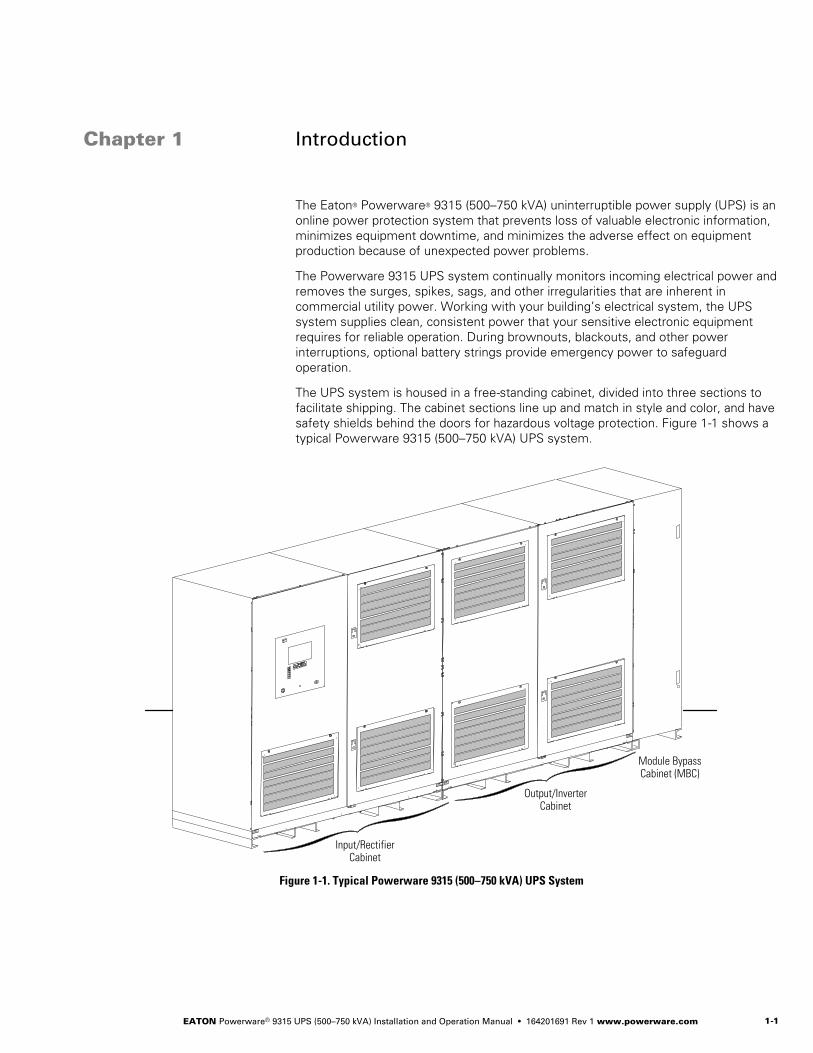
The UPS system is housed in a free-standing cabinet, divided into three sections tofacilitate shipping. The cabinet sections line up and match in style and color, and havesafety shields behind the doors for hazardous voltage protection. Figure 1-1 shows atypical Powerware 9315 (500–750 kVA) UPS system.
Module BypassCabinet (MBC)
Output/InverterCabinet
Input/RectifierCabinet
Figure 1-1. Typical Powerware 9315 (500–750 kVA) UPS System
Figure 1Table 1

INTRODUCTION
EATON Powerware® 9315 UPS (500–750 kVA) Installation and Operation Manual S 164201691 Rev 1 www.powerware.com1-2
1.1 UPS Features
The UPS has many standard features that provide cost-effective and consistentlyreliable power protection. The descriptions in this section provide a brief overview ofthe UPS standard features.
1.1.1 Installation Features
Power wiring can be routed through the top of each cabinet. External sensingand monitoring control wire must be installed according to UL Class I requirements.Class I wiring can be routed through the top of each cabinet.
1.1.2 Customer Interface
The UPS has the following communication features:
S Building Alarm Monitoring – The facility’s alarm system contacts can be connectedto four inputs in the UPS. The UPS uses these inputs to monitor the buildingalarms in addition to the UPS status. See Chapter 10, “Using Features andOptions,” for additional information.
S Summary Alarm Contacts – Summary alarm contacts are provided for connection toequipment at the facility, such as a light, an audible alarm, or a computer terminal.The equipment connected to this contact alerts you to a UPS alarm. SeeChapter 10, “Using Features and Options,” for additional information.
S Computer Interface – Two serial communication ports are standard on all units, andare electrically isolated from the UPS. You can use these ports to link the UPS tothe features described in Chapter 12, “Communication.”
S X-Slot® Communication Bay – One communication bay is available on the UPS toinstall an optional X-Slot card. See Chapter 12, “Communication,” for additionalinformation.
1.1.3 Customer Convenience Outlet
An uninterruptible 120 Vac, 0.2A, fuse-protected convenience outlet is provided tosupply power to the optional modem. It is located on the customer interface panel.
1.1.4 ABM® Technology
A three-stage charging system increases battery service life by optimizing rechargetime, and protects batteries from damage due to high current charging and inverterripple currents. Charging at high currents can overheat and damage batteries.
1.1.5 Automatic Battery Charge Current Limit
A preset limit restricts battery charging current to protect batteries from damage dueto high current charging. Charging at high currents can overheat and damagebatteries.

INTRODUCTION
EATON Powerware® 9315 UPS (500–750 kVA) Installation and Operation Manual S 164201691 Rev 1 www.powerware.com 1-3
1.2 Options and Accessories
Contact your Eaton sales representative for information about the following options:
1.2.1 5% Input Filter
The UPS can be equipped with an input filter. An input filter yields power factorcorrection that allows you to save on your initial installation and operating costs. Thefilter also reduces input harmonic current distortion and minimizes upstreaminterference that can damage sensitive hardware components.
1.2.2 Battery Racks
You can enhance the protection time provided by the UPS system by adding one ormore battery racks. The battery racks should be equipped with sealed,maintenance-free, lead-acid batteries. An external battery disconnect switch must beused. See Chapter 4, “Installing a Remote Battery Disconnect,” for additionalinformation.
1.2.3 External Fused Battery Disconnect
An optional external DC disconnect provides an automatic or manual means ofdisconnecting a battery string from the UPS. The disconnect is enclosed in afloor-mounted, free-standing box. You can install it anywhere between the remote DCsupply and the UPS, according to national and local codes.
The breaker switch on the remote battery disconnect is set according to the operationprocedures in Chapter 9, “UPS Operating Instructions.” When service personnel areperforming maintenance on the UPS or battery string, the switch should be set to theOFF position. See Chapter 4, “Installing a Remote Battery Disconnect,” for batterydisconnect requirements and installation instructions.
1.2.4 Upgrade Capability
The UPS is available in various output power ratings in both 50 and 60 Hz models. Ifyour power requirements increase, you can upgrade the UPS system to provide moreoutput power with a minimum impact on your facility.
1.2.5 Parallel Capacity/Redundant System
With Powerware Hot Sync technology and a System Bypass Module (SBM), theParallel Capacity/Redundant System allows two to eight uninterruptible powermodules (UPMs) to operate in parallel to provide more capacity than a single UPMand as backup for each other. The parallel capacity/redundant system can supply up to4000A, depending on the SBM used. In addition, when one UPM is taken out ofservice for maintenance or is not operating properly, the redundant UPM continues tosupply uninterrupted power to the critical load.

INTRODUCTION
EATON Powerware® 9315 UPS (500–750 kVA) Installation and Operation Manual S 164201691 Rev 1 www.powerware.com1-4
1.2.6 Monitoring and Communication
The following monitoring and communication options are available:
S Remote Monitor Panel (RMP) – An optional RMP contains backlit status indicators anda local horn, allowing you to monitor the UPS operational status and alarmcondition from virtually any location within your facility. This option is describedfurther in Chapter 10, “Using Features and Options.”
S Relay Interface Module (RIM) – An optional RIM uses relay contact closures toindicate the UPS operating status and alarm condition. The module uses a serialinterface line and may support up to eight critical loads. This option is describedfurther in Chapter 10, “Using Features and Options.”
S Supervisory Contact Module (SCM) – An optional SCM establishes an interfacebetween the Parallel Capacity/Redundant system manufacturer’s equipment andthe customer’s monitor. This interface allows the customer to monitor operationalstatus of the Parallel Capacity/Redundant system equipment. This option isdescribed further in Chapter 10, “Using Features and Options.”
S X-Slot Cards – Optional X-Slot cards support several protocols, such as SNMP,AS/400®, and Modbus®. See Chapter 12, “Communication,” for additionalinformation.
S eNotify Remote Monitoring and Diagnostic Service – An optional service that provides7x24 remote monitoring of 43 alarms, temperature/humidity and battery chargeinformation, daily heartbeat check, and monthly report. The eNotify Service alsoprovides customer notification of significant alarms, remote diagnostics, anddispatch of technicians. A ConnectUPS –X Web/SNMP Card is required in theX-Slot communication bay. An optional Powerware Environmental MonitoringProbe (EMP) is required for temperature/humidity monitoring. See Chapter 12,“Communication,” for additional information.
S Modem – An optional modem is available for use with the Remote Notificationfeature described in Chapter 12, “Communication.” Refer to the modemmanufacturer’s manual for modem operating instructions.
1.3 Basic System Configurations
The following basic UPS system configurations are possible:
S Single module UPS and one battery string
S Multi-module (parallel for capacity/redundancy) UPS system consisting of two ormore UPS modules, with one battery string for each module, and a PowerwareHot Sync Capacity module
S Multi-module (parallel for capacity/redundancy) UPS system consisting of two ormore UPS modules, with one common battery string, and a Powerware Hot Sync®
Capacity module
You can enhance the UPS system configuration by adding optional accessories, suchas an RMP, RIM, SCM, or remote emergency power-off (REPO) control.
t

INTRODUCTION
EATON Powerware® 9315 UPS (500–750 kVA) Installation and Operation Manual S 164201691 Rev 1 www.powerware.com 1-5
1.4 Safety Warnings
IMPORTANT SAFETY INSTRUCTIONSSAVE THESE INSTRUCTIONS
S This manual contains important instructions that should be followed during installation and maintenanceof the UPS and batteries. Please read all instructions before operating the equipment and save thismanual for future reference.
S The UPS cabinet is designed for industrial or computer room applications and contains safety shieldsbehind the front doors. However, the UPS system is a sophisticated power system and should be handledwith appropriate care.
DANGERThis UPS contains LETHAL VOLTAGES. All maintenance and service should be performed byAUTHORIZED SERVICE PERSONNEL ONLY.
WARNINGS Installation and maintenance should be performed only by qualified personnel.
S The UPS system contains its own energy source (batteries). The output terminals may carry live voltageeven when the UPS is disconnected from an AC source.
S To reduce the risk of fire or electric shock, install this UPS in a temperature and humidity controlled,indoor environment, free of conductive contaminants. Ambient temperature must not exceed 40°C(104°F). Do not operate near water or excessive humidity (95% maximum). The system is not intended foroutdoor use.
S Ensure all power is disconnected before performing installation or service.
S ELECTRIC ENERGY HAZARD. Do not attempt to alter any battery wiring or connectors. Attempting to alterwiring can cause injury.
CAUTIONS Batteries can present a risk of electrical shock or burn from high short-circuit current. Observe proper
precautions. Servicing should be performed by qualified service personnel knowledgeable of batteriesand required precautions. Keep unauthorized personnel away from batteries.
S Replace batteries with the same number and type of batteries as originally installed in the UPS.
S Proper disposal of batteries is required. Refer to local codes for disposal requirements.
S Never dispose of batteries in a fire. Batteries may explode when exposed to flame.
S Keep the cabinet doors on and secured to ensure proper cooling airflow and to protect personnel fromdangerous voltages inside the unit.
S Disconnect the charging source prior to connecting or disconnecting terminals.
S Determine if the battery is inadvertently grounded. If it is, remove the source of the ground. Contactingany part of a grounded battery can cause a risk of electric shock. An electric shock is less likely if youdisconnect the grounding connection before you work on the batteries.
S Do not operate the UPS system close to gas or electric heat sources.
S The operating environment should be maintained within the parameters stated in this manual.
S Keep surroundings uncluttered, clean, and free from excess moisture.
S Do not use this equipment for other than intended use.
S The use of accessory equipment not recommended by the manufacturer may cause an unsafe condition.
S Observe all DANGER, WARNING, and CAUTION notices affixed to the inside and outside of theequipment.

INTRODUCTION
EATON Powerware® 9315 UPS (500–750 kVA) Installation and Operation Manual S 164201691 Rev 1 www.powerware.com1-6
AVERTISSEMENT!S Les batteries peuvent présenter un risque de décharge électrique ou de brûlure par des courts-circuits de
haute intensité. Prendre les précautions nécessaires.
S Pour le remplacement, utiliser le même nombre et modéle des batteries.
ATTENTION!S Une mise au rebut réglementaire des batteries est obligatoire. Consulter les règlements en vigueur dans
votre localité.
S Ne jamais jeter les batteries au feu. L’exposition aux flammes risque de les faire exploser.
1.5 Conventions Used in This Manual
This manual uses these type conventions:
S Italic type represents variable information that you must replace with an actualvalue, or a directory or file name.
S Screen type represents information that appears on your screen.
S Bold type represents a command or option that you type or enter at a prompt.
Icon Description
Information notes call attention to important features or instructions.
[Keys] Brackets are used when referring to a specific key, such as [Enter] or [Ctrl].
In this manual, the term UPS refers only to the UPS cabinet and its internal elements.The term UPS system refers to the entire power protection system – the UPSmodules, battery strings, and options or accessories installed.
1.6 For More Information
Refer to the Powerware 9315 Parallel Capacity/Redundant UPS Installation andOperation Manual for the following additional information:
S SBM cabinet and optional accessories installation instructions, including sitepreparation, planning for installation, wiring and safety information, and detailedillustrations of the cabinet and optional accessories with dimensional andconnection point drawings.
S Parallel operation, including procedures for using the SBM cabinet with the UPS,responding to system events, and information about maintenance.
S Describes the SBM control panel and explains the SBM functions; discusses theSBM standard features and optional accessories; provides procedures for startingand stopping the parallel for capacity/redundancy system, and information aboutmaintenance and responding to system events.
S SBM RS-485 and RS-232 serial communication, including connecting optionalremote accessories to the SBM and enabling, disabling, and customizing buildingalarms.
Visit www.powerware.com or contact your Eaton service representative forinformation on how to obtain copies of this manual.

INTRODUCTION
EATON Powerware® 9315 UPS (500–750 kVA) Installation and Operation Manual S 164201691 Rev 1 www.powerware.com 1-7
1.7 Getting Help
If you need help with any of the following:
S Scheduling initial startup
S Regional locations and telephone numbers
S A question about any of the information in this manual
S A question this manual does not answer
Please call the Eaton Help Desk for Powerware products at:
United States: 1-800-843-9433 or 1-919-870-3028Canada: 1-800-461-9166 ext 260All other countries: Call your local service representative

INTRODUCTION
EATON Powerware® 9315 UPS (500–750 kVA) Installation and Operation Manual S 164201691 Rev 1 www.powerware.com1-8
This page intentionally left blank.

EATON Powerware® 9315 UPS (500–750 kVA) Installation and Operation Manual S 164201691 Rev 1 www.powerware.com 1-1
Section IInstallation

EATON Powerware® 9315 UPS (500–750 kVA) Installation and Operation Manual S 164201691 Rev 1 www.powerware.com1-2

EATON Powerware® 9315 UPS (500–750 kVA) Installation and Operation Manual S 164201691 Rev 1 www.powerware.com 2-1
Chapter 2 UPS Installation Plan and Unpacking
Use the following basic sequence of steps to install the UPS:
1. Create an installation plan for the UPS system (Chapter 2).
2. Prepare your site for the UPS system (Chapter 2).
3. Inspect, unpack, and unload the UPS cabinets (Chapters 2 and 3).
4. Wire the system (Chapter 3).
5. Install features, accessories, and/or options, as applicable (Chapters 4 through 6).
6. Complete the installation checklist (Chapter 3).
7. Have authorized service personnel perform preliminary operational checks andstartup.
NOTE Startup and operational checks must be performed by an authorized Eaton Customer ServiceEngineer, or the warranty terms specified on page 15-1 become void. This service is offered as part of thesales contract for the UPS. Contact your Eaton service representative in advance (usually a two-week notice isrequired) to reserve a preferred startup date.
2.1 Creating an Installation Plan
Before installing the UPS system, read and understand how this manual applies to thesystem being installed. Use the procedures and illustrations in the following chaptersto create a logical plan for installing the system.
2.1.1 Preparing Your Site
For the UPS system to operate at peak efficiency, the installation site should meetthe environmental parameters outlined in this manual. If the UPS is to be operated atan altitude higher than 1500m (5000 ft), contact your Eaton service representative forimportant information about high altitude operation. The operating environment mustmeet the weight, clearance, and environmental requirements specified inparagraph A.1 starting on page A-1.
The UPS cabinets use forced air cooling to regulate internal component temperature.Air inlets are in the front of the cabinet and outlets are in the top. You must allowclearance in front of and above each cabinet for proper air circulation (see Table B onpage A-1).
2.1.2 Environment Considerations
The life of the UPS system is adversely affected if the installation does not meet thefollowing guidelines:
1. The system must be installed on a level, sealed concrete pad or floor.
2. The system must be installed in a temperature-controlled indoor area free ofconductive contaminants.
Failure to follow guidelines may void your warranty.
Figure 2Table 2

UPS INSTALLATION PLAN AND UNPACKING
EATON Powerware® 9315 UPS (500–750 kVA) Installation and Operation Manual S 164201691 Rev 1 www.powerware.com2-2
2.1.3 Preparing for Wiring the UPS System
For external wiring requirements, including the minimum AWG size of external wiring,see Table E through Table G starting on page A-13. The power wiring connections forthis equipment are rated at 90°C. If the ambient temperature is greater than 30°C,higher temperature wire and/or larger size wire may be necessary. Control wiring forremote emergency power-off (REPO) and optional accessories (such as buildingalarms and monitoring interface) should be connected at the customer interfaceterminal blocks located inside the UPS using UL Class 1 wiring methods.
2.2 Inspecting and Unpacking Each Cabinet
Each cabinet is shipped bolted to wooden pallets and protected with outer protectivepackaging material and a plastic inner covering (see Figure 2-1).
Wooden Pallet
OuterPackaging
Figure 2-1. Cabinet as Shipped with Outer Packaging and Pallet
WARNINGThe UPS cabinets are extremely heavy (see Table A on page A-1). If unpacking instructions are not closelyfollowed, the cabinet may tip and cause serious injury.
CAUTIONS Do not install a damaged cabinet. Report any damage to the carrier and contact your Eaton service
representative immediately.
S Do not tilt the UPS cabinets more than 10° from vertical or the cabinet may tip over.
NOTE Verify that the forklift or pallet jack is rated to handle the weight of the cabinets (see Table A onpage A-1 for cabinet weights).
To unpack the cabinet:
1. Carefully inspect the outer packaging for evidence of damage during transit.
2. Use a forklift or pallet jack to move the packaged cabinet to the installation site,or as close as possible, before unpacking. Insert the forklift or pallet jack forksbetween the skids on the bottom of the unit.
3. Set each pallet on a firm, level surface, allowing a minimum clearance of4.6m (15 ft) on each side for removing the cabinets from the pallets.
4. If outer packaging is secured with steel bands, cut and remove the bands fromeach cabinet.

UPS INSTALLATION PLAN AND UNPACKING
EATON Powerware® 9315 UPS (500–750 kVA) Installation and Operation Manual S 164201691 Rev 1 www.powerware.com 2-3
5. Remove the protective cardboard covering from the cabinets, cutting whereindicated, using a knife blade no longer than 25 mm (1”).
6. Remove the plastic bag and foam packing material, and discard or recycle themin a responsible manner.
7. Inspect the contents for any evidence of physical damage, and compare eachitem with the Bill of Lading. If damage has occurred or shortages are evident,contact your Eaton service representative immediately to determine the extent ofthe damage and its impact upon further installation.
NOTE While waiting for installation, protect the unpacked cabinets from moisture, dust, and other harmfulcontaminants. Failure to store and protect the UPS system properly may void your warranty.

UPS INSTALLATION PLAN AND UNPACKING
EATON Powerware® 9315 UPS (500–750 kVA) Installation and Operation Manual S 164201691 Rev 1 www.powerware.com2-4
This page intentionally left blank.

EATON Powerware® 9315 UPS (500–750 kVA) Installation and Operation Manual S 164201691 Rev 1 www.powerware.com 3-1
Chapter 3 Installing the UPS System
This section describes the UPS system installation for single modules andmulti-modules, including: unloading the cabinets, UPS internal and external wiring,and interface connections.
3.1 Preliminary Installation Information
DANGERThis UPS contains LETHAL VOLTAGES. All repairs and service should be performed by AUTHORIZEDSERVICE PERSONNEL ONLY. There are NO USER SERVICEABLE PARTS inside the UPS.
WARNINGInstallation should be performed only by qualified personnel.
Refer to the following while installing the UPS system:
S See Appendix A for installation drawings and additional installation notes.
S Dimensions are in millimeters and inches.
S Do not tilt the UPS cabinets more than 10° from vertical or the cabinet may tipover.
S Remove the conduit landing plates to add conduit landing holes as required. Platematerial is 14 gauge steel (2 mm/0.075” thick).
S The Emergency UPS Off (EPO) and the Remote Emergency Power-off (REPO)buttons normally open all breakers in the UPS, shut down the UPS, and isolatepower from the critical load. However, the EPO and REPO may be configured totransfer the UPS to bypass and shut down the UPS. Local electrical codes mayalso require tripping protective devices upstream from the UPS.
S The UPS cabinets must be installed on a level, sealed concrete pad or floor.
S If perforated floor tiles are required for ventilation, place them in front of the UPS.See Table A on page A-1 for equipment weight.
S Details about control wiring are provided in each procedure for connecting optionsand features. Paragraph A.5 starting on page A-28 identifies the control wiringterminations.
S All circuit breakers provided as part of the UPS system that employ adjustable tripmechanisms have been set to their maximum settings. Based upon the energyavailable and other equipment located on-site, these settings may need to beadjusted to ensure proper system operation and coordination. It is the customer’sresponsibility to conduct a breaker coordination study, so that these breakers canbe adequately set for the site.
Figure 3Table 3

INSTALLING THE UPS SYSTEM
EATON Powerware® 9315 UPS (500–750 kVA) Installation and Operation Manual S 164201691 Rev 1 www.powerware.com3-2
3.2 Unloading the UPS Cabinets from the Pallet
WARNINGS The UPS cabinets are heavy (see Table A on page A-1). If unpacking instructions are not closely followed,
the cabinet may tip and cause serious injury.
S Do not install a damaged cabinet. Report any damage to the carrier and contact your Eaton servicerepresentative immediately.
S Do not tilt the UPS or optional cabinets more than 10° from vertical or the cabinet may tip over.
NOTE Verify that the forklift or pallet jack is rated to handle the weight of the cabinet (see Table A onpage A-1 for cabinet weights).
Each UPS cabinet is bolted to a wooden pallet supported by wood skids.
To remove the pallet:
1. If not already moved, use a forklift or pallet jack to move the cabinet to theinstallation site, or as close as possible, before unloading from the pallet. Insertthe forklift or pallet jack forks between the skids on the bottom of the unit.
2. Remove the hardware securing each UPS cabinet to the pallet.
3. Using a forklift, raise the UPS cabinet until the cabinet bottom clears the pallet byapproximately 3 mm (1/8”).
4. When the UPS cabinet is clear of the pallet, pull the pallet from under thecabinet. Discard or recycle the pallets in a responsible manner.
5. Carefully lower the UPS cabinet until the cabinet base touches the floor.
6. Repeat Steps 3 through 5 for the remaining UPS cabinets.
3.3 Single Module Installation
To install a single module UPS system, perform the procedures in the followingparagraphs. If a multi-module system is being installed, proceed to “Multi-ModuleInstallation” on page 3-4.
3.3.1 Installing UPS Internal Power and Control Wiring
NOTE The cables used in Steps 2 through 4 are coiled inside the Input/Rectifier cabinet and are attachedat the factory to the rectifier output. The cables used in Steps 7 and 8 are coiled inside the Module BypassCabinet (MBC) and are attached at the factory to the input of the MBC.
To install the UPS internal power and control wiring (see Table H on page A-16 fortightening torques and paragraph A.4 starting on page A-22 for terminal locations):
1. Remove the plastic shield covering the inverter input section of theOutput/Inverter cabinet.
2. Route the DC Link cables from the rectifier output (Input/Rectifier cabinet) to theinverter input (Output/Inverter cabinet) through the knockouts in the cabinetsides.
3. Connect the positive DC Link power wiring to the inverter input. Connect twocables to each inverter.

INSTALLING THE UPS SYSTEM
EATON Powerware® 9315 UPS (500–750 kVA) Installation and Operation Manual S 164201691 Rev 1 www.powerware.com 3-3
4. Connect the negative DC Link power wiring to the inverter input. Connect twocables to each inverter.
5. Reinstall the plastic shield to the inverter input section.
6. Remove the plastic shield covering the inverter output section of theOutput/Inverter cabinet.
7. Route the MBC input cables from the MBC to the inverter output(Output/Inverter cabinet) through the knockouts in the cabinet sides.
8. Connect phase A, B, and C and Neutral power wiring from the MBC to therespective inverter output.
9. Route the ground braid from the top of the Output/Inverter cabinet to theInput/Rectifier cabinet through the cabinet knockouts. The ground braid issecured at the factory to the Output/Inverter cabinet mounting stud.
10. Connect the ground braid to the Input/Rectifier cabinet mounting stud andsecure.
11. Route the ground braid from the top of the MBC to the Output/Inverter cabinetthrough the cabinet knockouts. The ground braid is secured at the factory to theMBC mounting stud.
12. Connect the ground braid to the Output/Inverter cabinet mounting stud andsecure.
13. Reinstall the plastic shield to the inverter output section.
14. Connect the Output/Inverter 15-pin control wiring harness connector to theInput/Rectifier 15-pin control wiring harness connector. See Figure A-12 onpage A-22 for connector locations.
15. Connect the MBC 15-pin control wiring harness connector to the Output/Inverter15-pin control wiring harness connector. See Appendix A for connector locations.
16. Connect the 3-pin control wiring harness connector P6 from the MBC toconnector J6 on the Inverter Number 2 control board in the Output/Invertercabinet. See Figure A-14 on page A-24 and Figure A-16 on page A-26 forconnector locations.
3.3.2 Installing UPS External Power and Control Wiring
To install the UPS external power and control wiring (see Appendix A for wiring andtermination requirements and wiring access information):
1. Remove the sheet-metal shield covering the input terminal area in theInput/Rectifier cabinet to gain access to the Battery I/O customer interfaceand CB2TB. See Figure A-12 page A-22 for the shield location.
NOTE Remove the Input/Rectifier cabinet conduit landing plate to punch conduit holes.
2. Connect phase A, B, and C power wiring from the source to the respectiverectifier inputs in the Input/Rectifier cabinet.
3. Connect the positive and negative DC power wiring from the batteries to therespective DC inputs in the Input/Rectifier cabinet.

INSTALLING THE UPS SYSTEM
EATON Powerware® 9315 UPS (500–750 kVA) Installation and Operation Manual S 164201691 Rev 1 www.powerware.com3-4
NOTE Remove the entire MBC top panel to punch conduit holes.
4. Connect phase A, B, and C power wiring from the bypass source to therespective bypass inputs in the MBC.
5. Connect phase A, B, and C and Neutral power wiring from the MBC output tothe critical load.
6. Connect the control wiring (battery breaker open and close signals and shunt DCdisconnect) between the external battery disconnect and the UPS.
7. After wiring the UPS system to the facility power and critical load, be sure toground the system according to local and/or national electrical wiring codes.
8. Install the batteries according to the battery and battery rack manufacturer’sinstructions and all applicable codes and regulations, including the NationalElectrical Code (NEC), Article 480.
NOTE There is no DC disconnect device within the UPS.
NOTE The DC input to the UPS is protected by internal fuses F30 and F31.
3.4 Multi-Module Installation
To install a multi-module system using a System Bypass Module (SBM), perform theprocedures in the following paragraphs.
3.4.1 Installing UPS Internal Power and Control Wiring
NOTE The cables used in Steps 2 through 4 are coiled inside the Input/Rectifier cabinet and are attachedat the factory to the rectifier output.
To install the UPS internal power and control wiring in a multi-module system (seeAppendix A for terminal locations and wiring access information):
1. Remove the plastic shield covering the inverter input section of theOutput/Inverter cabinet.
2. Route the DC Link cables from the rectifier output (Input/Rectifier cabinet) to theinverter input (Output/Inverter cabinet) through the knockouts in the cabinetsides.
3. Connect the positive DC Link power wiring to the inverter input. Connect twocables to each inverter. For tightening torque, see Table H on page A-16.
4. Connect the negative DC Link power wiring to the inverter input. Connect twocables to each inverter. For tightening torque, see Table H on page A-16.
5. Reinstall the plastic shield to inverter input section.
6. Route the ground braid from the top of the Output/Inverter cabinet to theInput/Rectifier cabinet through the cabinet knockouts. The ground braid issecured at the factory to the Output/Inverter cabinet mounting stud.
7. Connect the ground braid to the Input/Rectifier cabinet mounting stud andsecure.

INSTALLING THE UPS SYSTEM
EATON Powerware® 9315 UPS (500–750 kVA) Installation and Operation Manual S 164201691 Rev 1 www.powerware.com 3-5
8. Connect the Output/Inverter 15-pin control wiring harness connector to theInput/Rectifier 15-pin control wiring harness connector. See Figure A-12 onpage A-22 and Figure A-14 on page A-24 for connector locations.
9. Remove the plastic shield covering the inverter output section of theOutput/Inverter cabinet.
10. Refer to the Powerware 9315 Parallel Capacity/Redundant UPS Installation andOperation Manual for SBM input wiring procedures.
11. Reinstall the plastic shield to the inverter output section.
3.4.2 Installing UPS External Power and Control Wiring
To install the UPS external power and control wiring (see Appendix A for wiring andtermination requirements and wiring access information):
1. Remove the sheet-metal shield covering the input terminal area in theInput/Rectifier cabinet to gain access to the Battery I/O customer interfaceand CB2TB. See Figure A-12 on page A-22 for the shield location.
NOTE Remove the Input/Rectifier cabinet conduit landing plate to punch conduit holes.
2. Connect phase A, B, and C power wiring from the source to the respectiverectifier inputs in the Input/Rectifier cabinet.
3. Connect positive and negative DC power wiring from the batteries to therespective DC inputs in the Input/Rectifier cabinet.
4. Connect the control wiring (battery breaker open and close signals and shunt DCdisconnect) between the external battery disconnect and the UPS.
5. Refer to the Powerware 9315 Parallel Capacity/Redundant UPS Installation andOperation Manual for SBM output wiring procedures.
6. After wiring the UPS system to the facility power and critical load, be sure toground the system according to local and/or national electrical wiring codes.
7. Install the batteries according to the battery and battery rack manufacturer’sinstructions and all applicable codes and regulations, including NEC, Article 480.
NOTE There is no DC disconnect device within the UPS.
NOTE The DC input to the UPS is protected by internal fuses F30 and F31.

INSTALLING THE UPS SYSTEM
EATON Powerware® 9315 UPS (500–750 kVA) Installation and Operation Manual S 164201691 Rev 1 www.powerware.com3-6
3.5 Installing Input/Rectifier Customer Connections
NOTE If you are installing connections to the Battery I/O terminal connections and terminal board CB2TB,install conduit between each device and the UPS cabinet for wiring these options.
See paragraph A.5 on page A-28 for the interface point locations within the UPScabinet.
To prepare the UPS for wiring to customer connections:
1. Verify that the UPS system is turned off and all power sources are removed. See“Shutting Down the UPS and Critical Load” on page 9-6 for shutdowninstructions.
2. Remove the sheet-metal shield covering the input terminal area in theInput/Rectifier cabinet to gain access to the Battery I/O customer interfaceand CB2TB. See Figure A-12 on page A-22 for the shield location.
3. See paragraph A.5 on page A-28 for terminal assignments, and wiring andtermination requirements.
3.6 Installing Output/Inverter Customer Connections
NOTE If you are installing connections to a REPO device, building alarm, or relay contacts, install conduitbetween each device and the UPS cabinet.
See paragraph A.5 on page A-28 for the interface point locations within the UPScabinet.
To prepare the UPS for wiring to customer connections:
1. Verify that the UPS system is turned off and all power sources are removed. See“Shutting Down the UPS and Critical Load” on page 9-6 for shutdowninstructions.
2. See paragraph A.5 on page A-28 for terminal assignments, and wiring andtermination requirements.
3.7 Installing Accessories
To install an optional REPO switch, see Chapter 5, “Installing a Remote EmergencyPower-off Control.” To install optional accessories [such as the Remote Monitor Panel(RMP) or X-Slot connections], see Chapter 6, “Installing Optional Accessories.” Whenaccessory installation is complete, proceed to paragraph 3.8.
3.8 Initial Startup
Startup and operational checks must be performed by an authorized Eaton CustomerService Engineer, or the warranty terms specified on page 15-1 become void. Thisservice is offered as part of the sales contract for the UPS. Contact your Eaton servicerepresentative in advance (usually a two week notice is required) to reserve apreferred startup date.

INSTALLING THE UPS SYSTEM
EATON Powerware® 9315 UPS (500–750 kVA) Installation and Operation Manual S 164201691 Rev 1 www.powerware.com 3-7
3.9 Completing the Installation Checklist
The final step in installing the UPS system is completing the following installationchecklist. This checklist ensures that you have completely installed all hardware,cables, and other equipment. Completing all items listed on the checklist will ensure asmooth installation. You should make a copy of the installation checklist before fillingit out, and retain the original.
After the installation is complete, a service representative will be able to verify theUPS system operation and commission it to support the critical load. The servicerepresentative cannot perform any installation tasks other than verifying software andoperating setup parameters. Service personnel may request a copy of the completedinstallation checklist to be sure you have completed all applicable equipmentinstallation.
NOTE The installation checklist MUST be completed prior to starting the UPS system for the first time.

INSTALLING THE UPS SYSTEM
EATON Powerware® 9315 UPS (500–750 kVA) Installation and Operation Manual S 164201691 Rev 1 www.powerware.com3-8
Installation Checklist
- All packing materials and restraints have been removed from each cabinet.
- Each cabinet in the UPS system is placed in its final installation location.
- A ground bond is installed between any cabinets that are bolted together.
- All switchboards, conduits, and cables are properly routed to the UPS and auxiliary cabinets.
- All power cables are properly sized and terminated.
- A ground conductor is properly installed.
- If a bypass input neutral connection is used, no other N-G bonds exist downstream from the UPS.
- Battery cables and harnesses are terminated on E4 and E5.
- Internal battery cabinet connections have been completed (bus bars, plugs, etc.).
- Shunt trip signal wiring is connected from UPS to battery breaker(s).
- Air conditioning equipment is installed and operating correctly.
- The area around the UPS system is clean and dust-free. (It is recommended that the UPS be installed on a level,sealed concrete pad or floor.)
- Adequate workspace exists around the UPS and other cabinets.
- Adequate lighting is provided around all UPS equipment.
- A 120V service outlet is located within 7.6m (25 ft) of the UPS equipment.
- Each Remote Monitor Panel (RMP) is mounted in its installed location. (OPTIONAL)
- The control wiring for each RMP is terminated inside the UPS cabinet. (OPTIONAL)
- The remote emergency power-off (REPO) device is mounted in its installed location and its wiring terminated insidethe UPS cabinet. (OPTIONAL)
- Summary alarms and/or building alarms are wired appropriately. (OPTIONAL)
- A Relay Interface Module (RIM) is mounted in its installed location and its wiring is terminated inside the UPS cabinet.(OPTIONAL)
- A remote battery disconnect control is mounted in its installed location and its wiring is terminated inside the UPS andbattery cabinets. (OPTIONAL)
- Circuit breakers with adjustable trip mechanisms adjusted to match site requirements.
- Debris shields covering ventilation grills are removed from all cabinets.
- Startup and operational checks are performed by an authorized Eaton Customer Service Engineer.

INSTALLING THE UPS SYSTEM
EATON Powerware® 9315 UPS (500–750 kVA) Installation and Operation Manual S 164201691 Rev 1 www.powerware.com 3-9
Notes
_________________________________________________________________________
_________________________________________________________________________
_________________________________________________________________________
_________________________________________________________________________
_________________________________________________________________________
_________________________________________________________________________
_________________________________________________________________________
_________________________________________________________________________
_________________________________________________________________________
_________________________________________________________________________
_________________________________________________________________________
_________________________________________________________________________
_________________________________________________________________________
_________________________________________________________________________
_________________________________________________________________________
_________________________________________________________________________

INSTALLING THE UPS SYSTEM
EATON Powerware® 9315 UPS (500–750 kVA) Installation and Operation Manual S 164201691 Rev 1 www.powerware.com3-10
This page intentionally left blank.

EATON Powerware® 9315 UPS (500–750 kVA) Installation and Operation Manual S 164201691 Rev 1 www.powerware.com 4-1
Chapter 4 Installing a Remote Battery Disconnect
The remote battery disconnect is crated separately for shipping. The enclosure isdesigned to be free-standing. You can install a remote battery disconnect anywherebetween the remote DC supply and the UPS, according to national and local codes.Figure 4-1 shows a typical remote battery disconnect enclosure.
The remote battery disconnect is set according to the operation procedures inChapter 9, “UPS Operating Instructions.” When service personnel are performingmaintenance on the UPS or battery string, the disconnect should be set to the OFFposition.
Operating HandleON Position
Operating HandleOFF Position
Figure 4-1. Remote Battery Disconnect Enclosure
Consider the following general notes before beginning installation:
S There is no DC disconnect device within the UPS.
S The DC input to the UPS is only protected by internal fuses F30 and F31.
S The UPS DC disconnect trip signal from CB2TB, terminals 9 and 10 (shunt trip)must be connected to the DC source disconnect device.
S See Figure A-30 on page A-42 for battery disconnect dimensions.
S See paragraph A.3 on page A-12 for specific ratings and wiring requirements.
S The material and labor for external wiring requirements is to be supplied by others.
S The knockout pattern for the disconnect is determined by others at the time ofinstallation.
S Power cables and control wiring must be installed in separate conduit.
S The ground conductor is to be sized per National Electrical Code (NEC), Article 250and local electrical code requirements.
S The maximum current listed is at the minimum DC operating voltage.
Figure 4Table 4

INSTALLING A REMOTE BATTERY DISCONNECT
EATON Powerware® 9315 UPS (500–750 kVA) Installation and Operation Manual S 164201691 Rev 1 www.powerware.com4-2
S Nominal voltages listed in this chapter are for a lead-acid batteries rated per NEC at2.00 Vdc per cell.
S Battery strings must be installed according to all applicable codes and regulations,including NEC, Article 480.
S The UPS to battery cable should be sized for a total maximum voltage dropof 1% nominal DC Link voltage at maximum current.
S Table 4-1 details the power cable terminations.
S The remote battery disconnect weighs approximately 60.3 kg (133 lb).It has an ampere interrupting capacity (AIC) of 100,000 at 500 Vdc.
Table 4-1. Remote Battery Disconnect Power Terminations
Number and Type of Accessories Permitted
Terminal Terminal Function Size of Termination Tightening TorqueNm (lb ft) Bolt Size
E4 (+) UPS Battery Input (+) See Table H on page A-16
E5 (–) UPS Battery Input (–) See Table H on page A-16
Breaker (+) Battery Disconnect (+) 8 – 1 Bolt MountingBus Bar
76 (56) 1/2”
Breaker (–) Battery Disconnect (–) 8 – 1 Bolt MountingBus Bar
76 (56) 1/2”
Breaker (jumper) Battery Disconnect(jumper)
8 – 1 Bolt MountingBus Bar
76 (56) 1/2”
Table 4-2. Remote Battery Disconnect Circuit Breaker Ratings
UPS Model Circuit Breaker Rating DC Voltage
9315-750/500 1600 480
9315-750/625 2000 480
9315-750/750 2500 480

EATON Powerware® 9315 UPS (500–750 kVA) Installation and Operation Manual S 164201691 Rev 1 www.powerware.com 5-1
Chapter 5 Installing a Remote Emergency Power-off Control
A latching-type REPO switch can be used in an emergency to shut down the UPS andremove power to the critical load from a location away from where the UPS isinstalled. Figure 5-1 shows a REPO switch.
EMERGENCY OFFUNINTERRUPTIBLE POWER SYSTEM
To UPM To Other Equipment
Figure 5-1. Remote Emergency Power-off (REPO) Control
NOTE Before installing a REPO, verify that the UPS was installed according to the instructions in Chapter 3,“Installing the UPS System.”
To install a REPO station:
1. Verify that the UPS system is turned off and all power sources are removed. SeeChapter 9, “UPS Operating Instructions,” for shutdown instructions.
2. Securely mount the REPO station. Recommended locations include operator’sconsoles or near exit doors. See Figure A-25 page A-37 for enclosure dimensionsand wiring knockouts.
3. Install wiring from the REPO station using ½” conduit through the cable entryknockout in the top of the UPS Output/Inverter cabinet. See Appendix A forconduit landing area, terminal board location, and terminal wiring assignments.
4. Connect the REPO wiring as shown in Table 5-1 and Figure 5-2:
Table 5-1. REPO Wire Terminations
From REPO Station(s) To Customer InterfaceTerminal Board CUSTTB in UPS
Output/Inverter Cabinet
Remarks
TB1-4 CUSTTB-9 Twisted Wires (2)TB1-5 CUSTTB-10
Twisted Wires (2)14–18 Gauge
Figure 5Table 5

INSTALLING A REMOTE EMERGENCY POWER-OFF CONTROL
EATON Powerware® 9315 UPS (500–750 kVA) Installation and Operation Manual S 164201691 Rev 1 www.powerware.com5-2
NOTE REPO switch rating is 24 Vdc, 1A minimum if supplied by the customer. The REPO switch must be alatching-type switch with a dedicated circuit.
REPOSwitch
TwistedWires (2)
9
10
CUSTTB
Figure 5-2. REPO Wiring
5. If you are installing multiple REPO stations, wire additional stations in parallelwith the first REPO.
6. If required, install ½” conduit and wiring from the REPO station to trip circuitry ofupstream protective devices. A normally open contact is provided, as shown inFigure 5-2. REPO switch wiring must be according to UL Class I requirements.
7. Secure the UPS by reversing all steps taken to prepare it for REPO installation.

EATON Powerware® 9315 UPS (500–750 kVA) Installation and Operation Manual S 164201691 Rev 1 www.powerware.com 6-1
Chapter 6 Installing Optional Accessories
This chapter contains installation information for the following options:
S Monitoring accessories: Remote Monitor Panel (RMP), Relay Interface Module(RIM), and Supervisory Contact Module (SCM)
S X-Slot cards
NOTE When installing interface connections (such as an RMP, RIM, or SCM), install conduit between eachdevice and the UPS cabinet.
A maximum of two monitoring accessories (RMPs, RIMs, or SCMs) can be installed.An X-Slot card can also be installed with the monitoring accessories. See Table 6-1 forthe number of accessories permitted.
Table 6-1. Optional Monitoring Accessories
Number and Type of Accessories Permitted
RMP RIM SCM X-Slot
2 — — 1
— 2 — 1
— — 2 1
1 1 — 1
1 — 1 1
— 1 1 1
Figure 6Table 6

INSTALLING OPTIONAL ACCESSORIES
EATON Powerware® 9315 UPS (500–750 kVA) Installation and Operation Manual S 164201691 Rev 1 www.powerware.com6-2
6.1 Installing an RMP
As an option, you can install an RMP to monitor the UPS system operation fromvirtually any location within your facility, up to 152.4m (500 ft) from the UPS. You canflush-mount or surface-mount an RMP on a desktop or on a wall, wherever you havea serial interface line. Figure 6-1 shows an RMP. Figure A-26 on page A-38 shows theenclosure dimensions and cable exit openings.
Flush Mount
Surface Mount(for hanging)
Wires Must beTwisted
Figure 6-1. RMP

INSTALLING OPTIONAL ACCESSORIES
EATON Powerware® 9315 UPS (500–750 kVA) Installation and Operation Manual S 164201691 Rev 1 www.powerware.com 6-3
To install an RMP:
1. Verify that the UPS system is turned off and all power sources are removed. SeeChapter 9, “UPS Operating Instructions,” for shutdown instructions.
2. Remove the access plate on top of the UPS Input/Rectifier cabinet to gain accessto the customer interface panel (see Figure A-13 on page A-23).
3. Securely mount the RMP.
4. Install wiring from the RMP using ½” conduit through the cable entry knockout inthe top of the UPS Input/Rectifier cabinet. See Figure A-13 on page A-23 for theconduit landing area location.
5. In the spare parts kit, locate the RMP adapter cable assembly (see Figure 6-2).Mate the DB-9 connector on the back of the terminal block to the DB-9connector (Port 1) on the UPS customer interface panel (see Figure A-19 onpage A-30). Use two screws from the spare parts kit to secure the terminal blockbracket to the customer interface panel.
Connect toPort 1 (DB-9) on
Customer Interface PanelFuse
TerminalBlock(TB3)
Figure 6-2. Terminal Block Bracket

INSTALLING OPTIONAL ACCESSORIES
EATON Powerware® 9315 UPS (500–750 kVA) Installation and Operation Manual S 164201691 Rev 1 www.powerware.com6-4
6. Connect the RMP wiring to the terminal block using terminations shown inTable 6-2.
Table 6-2. RMP Wire Terminations
From RMP A To UPS Remarks
TB1-4 TB3-1
TB1-5 TB3-2 Twisted wires (4)TB1-6 TB3-3
Twisted wires (4)1–2 turns per 3”
TB1-7 TB3-4
From RMP B (If Used) To UPS Remarks
TB1-4 TB3-5
TB1-5 TB3-6 Twisted wires (4)TB1-6 TB3-7
Twisted wires (4)1–2 turns per 3”
TB1-7 TB3-8
7. To check the RMP operation, ensure that the UPS system is supplying the loadvia the inverter or bypass. If the RMP indicators show the appropriate status,then it is operating correctly.
If the communication link between the UPS and the RMP is not present, theRMP conducts a self-test (all indicators flash and the horn beeps at one-secondintervals); check all harness connectors and the fuse for proper seating. If allconnections are secure but the RMP continues to self-test, replace the fuse withthe spare included in the hardware kit. If this does not correct the problem,contact your Eaton service representative for verification that the RMP is workingcorrectly.
8. To test the light emitting diode (LED) lamps behind the indicators, press and holdthe horn silence button for three seconds. All the indicators illuminate and thehorn sounds continuously until you release the button. If any indicator does notilluminate, its LED lamp may need to be replaced. Contact your Eaton servicerepresentative if you have a problem with the LEDs.
9. Repeat Steps 1 through 8 if you are installing another RMP.
10. If you are installing an RIM or SCM in addition to an RMP, proceed toparagraph 6.2 or 6.3, respectively; otherwise, secure the access plate on top ofthe UPS Input/Rectifier cabinet.

INSTALLING OPTIONAL ACCESSORIES
EATON Powerware® 9315 UPS (500–750 kVA) Installation and Operation Manual S 164201691 Rev 1 www.powerware.com 6-5
6.2 Installing an RIM
The optional RIM uses relay contact closures to indicate the UPS system operatingstatus and alarm condition. The module uses an RS-422 serial interface line and maysupport up to eight critical loads. Figure 6-3 shows the RIM with its four 15-pin D-subconnectors labeled J1 through J4. See Figure A-27 and Figure A-28, starting onpage A-39, for enclosure dimensions and wiring knockouts.
Flush Mount
Surface Mount(for hanging)
Continuesat UPS
J2J1 J4J3
15-Pin D-SubConnectors
RIM
Figure 6-3. RIM
1. Verify that the UPS system is turned off and all power sources are removed. SeeChapter 9, “UPS Operating Instructions,” for shutdown instructions.
2. Remove the access plate on top of the UPS Input/Rectifier cabinet to gain accessto the customer interface panel (see Figure A-13 on page A-23).
3. Securely mount the RIM.
4. Install wiring from the RIM using ½” conduit through the cable entry knockout inthe top of the UPS Input/Rectifier cabinet. See Figure A-13 on page A-23 for theconduit landing area location.
5. If not already installed, locate the RMP adapter cable assembly in the spare partskit (see Figure 6-4). Mate the DB-9 connector on the back of the terminal block tothe DB-9 connector (Port 1) on the UPS customer interface panel (seeFigure A-19 on page A-30). Use two screws from the spare parts kit to securethe terminal block bracket to the customer interface panel.

INSTALLING OPTIONAL ACCESSORIES
EATON Powerware® 9315 UPS (500–750 kVA) Installation and Operation Manual S 164201691 Rev 1 www.powerware.com6-6
Connect toPort 1 (DB-9) on
Customer Interface Panel Fuse
TerminalBlock(TB3)
Figure 6-4. Terminal Block Bracket
6. Connect RIM wiring to the terminal block using the terminations shown inTable 6-3.
Table 6-3. RIM Wire Terminations
From RIM A To UPS Remarks
TB1-4 TB3-1
TB1-5 TB3-2 Twisted wires (4)TB1-6 TB3-3
Twisted wires (4)1–2 turns per 3”
TB1-7 TB3-4
From RIM B (If Used) To UPS Remarks
TB1-4 TB3-5
TB1-5 TB3-6 Twisted wires (4)TB1-6 TB3-7
Twisted wires (4)1–2 turns per 3”
TB1-7 TB3-8
7. Contact your Eaton service representative for verification and testing of the RIMand its connections prior to making connections to J1 through J4.
You can order interface cables separately for connecting to the 15-pin D-subconnectors.
8. Repeat Steps 1 through 7 if you are installing another RIM.
9. If you are installing an SCM in addition to an RIM, proceed to paragraph 6.3;otherwise, secure the access plate on top of the UPS Input/Rectifier cabinet.

INSTALLING OPTIONAL ACCESSORIES
EATON Powerware® 9315 UPS (500–750 kVA) Installation and Operation Manual S 164201691 Rev 1 www.powerware.com 6-7
6.3 Installing an SCM
The optional SCM shown in Figure 6-5 provides contacts for monitoring UPS systemstatus. See Figure A-29 page A-41 for enclosure dimensions and knockout patterns.
TB2
Surface Mount(for hanging)
Wires Must be Twisted
Flush Mount
Figure 6-5. SCM
1. Verify that the UPS system is turned off and all power sources are removed. SeeChapter 9, “UPS Operating Instructions,” for shutdown instructions.
2. Remove the access plate on top of the UPS Input/Rectifier cabinet to gain accessto the customer interface panel (see Figure A-13 on page A-23).
3. Securely mount the SCM.
4. Install wiring from the SCM using ½” conduit through the cable entry knockout inthe top of the UPS Input/Rectifier cabinet. See Figure A-13 on page A-23 for theconduit landing area location.
5. If not already installed, locate the RMP adapter cable assembly in the spare partskit (see Figure 6-6). Mate the DB-9 connector on the back of the terminal block tothe DB-9 connector (Port 1) on the UPS customer interface panel (seeFigure A-19 on page A-30). Use two screws from the spare parts kit to securethe terminal block bracket to the customer interface panel.

INSTALLING OPTIONAL ACCESSORIES
EATON Powerware® 9315 UPS (500–750 kVA) Installation and Operation Manual S 164201691 Rev 1 www.powerware.com6-8
Connect toPort 1 (DB-9) on
Customer Interface PanelFuse
TerminalBlock(TB3)
Figure 6-6. Terminal Block Bracket
6. Connect the SCM wiring to the terminal block using the terminations shown inTable 6-4.
Table 6-4. SCM Wire Terminations
From SCM A To UPS Remarks
TB1-4 TB3-1
TB1-5 TB3-2 Twisted wires (4)TB1-6 TB3-3
Twisted wires (4)1–2 turns per 3”
TB1-7 TB3-4
From SCM B (If Used) To UPS Remarks
TB1-4 TB3-5
TB1-5 TB3-6 Twisted wires (4)TB1-6 TB3-7
Twisted wires (4)1–2 turns per 3”
TB1-7 TB3-8
7. Contact your Eaton service representative for verification and testing of the SCMand its connections prior to making connections to terminal strip TB2 shown inFigure 6-7.
8. Repeat Steps 1 through 7 if you are installing another SCM.
9. Secure the access plate on top of the UPS Input/Rectifier cabinet.

INSTALLING OPTIONAL ACCESSORIES
EATON Powerware® 9315 UPS (500–750 kVA) Installation and Operation Manual S 164201691 Rev 1 www.powerware.com 6-9
System Normal
No Redundancy
On Generator
Bypass Not Available
On Battery
UPS Alarm
On Bypass
Shutdown Imminent
Figure 6-7. SCM TB2
NOTE Supervisory contacts are rated at 2.0A at 28 Vdc or 120 Vac and 0.15A at 115 Vdc.
NOTE Supervisory contacts require external power supply. Internal 24 Vdc is not capable of supplyingcontact current.

INSTALLING OPTIONAL ACCESSORIES
EATON Powerware® 9315 UPS (500–750 kVA) Installation and Operation Manual S 164201691 Rev 1 www.powerware.com6-10
6.4 Installing X-Slot Cards
NOTE LAN and telephone drops for use with X-Slot cards must be provided by facility planners or thecustomer.
NOTE For setup of an X-Slot card, please contact Eaton (see page 1-7).
To install the X-Slot cards:
1. If not already installed, install the LAN, telephone, or other cables.
2. Remove the access plate on top of the UPS Input/Rectifier cabinet to gain accessto the customer interface panel (see Figure A-13 on page A-23).
3. Remove the X-Slot cover plate to gain access to the X-Slot communication bay(see Figure A-19 on page A-30).
4. Install the X-Slot card into the communication bay.
5. Route and install the LAN, telephone, and other cables to the appropriate X-Slotcard.
6. Refer to the manual supplied with the X-Slot card for operator instructions.

EATON Powerware® 9315 UPS (500–750 kVA) Installation and Operation Manual S 164201691 Rev 1 www.powerware.com 6-11
Section IIOperation

EATON Powerware® 9315 UPS (500–750 kVA) Installation and Operation Manual S 164201691 Rev 1 www.powerware.com6-12

EATON Powerware® 9315 UPS (500–750 kVA) Installation and Operation Manual S 164201691 Rev 1 www.powerware.com 7-1
Chapter 7 Understanding UPS Operation
The Powerware 9315 is a continuous duty, solid-state UPS that supports thefollowing equipment: process control, data processing, telecommunications/PBX,research, and medical. The Powerware 9315 maintains power to the critical loadsduring commercial electrical power brownout, blackout, overvoltage, undervoltage,and out-of-tolerance frequency conditions.
In this manual, the power required by your equipment is called the critical load. The UPSsupplies the critical load with conditioned power that is synchronized with your utilitypower. Figure 7-1 shows the main elements of the UPS system.
AC Outputto CriticalLoad
AC Input toRectifier/
Charger
BypassBreaker
CB4
InputFilter
OutputBreaker
CB3
BackfeedProtection
Breaker FBP
Battery String
Output/InverterInput/Rectifier
BatteryBreakerCB2
F30F31
InputTransformer
InputBreaker
CB1
AC Input toBypass
Module Bypass Cabinet (MBC)
InputFilter Digital
Metering
Rectifier/Charger
Inverter
PowerProcessing Unit
OutputTransformer
StaticSwitch
Figure 7-1. Main Elements of the UPS System
The emergency bypass consists of a static switch, a wraparound bypass breaker(CB4) and a Backfeed Protection Breaker (FBP). The FBP is located in series with thestatic switch and opens so that the UPS cannot backfeed the bypass source.
For manual transfers to bypass, the static switch is not used. During the transfer, CB4is closed and verified and then inverter output breaker CB3 is opened. For transfers ofthe load from bypass to the UPS, CB3 is closed and verified and then CB4 is opened.The static switch is armed and ready during both types of transfers.
Figure 7Table 7

UNDERSTANDING UPS OPERATION
EATON Powerware® 9315 UPS (500–750 kVA) Installation and Operation Manual S 164201691 Rev 1 www.powerware.com7-2
If utility power is interrupted or falls outside the parameters specified in Chapter 14,“Product Specifications,” the UPS uses a backup battery supply to maintain power tothe critical load for a specified period of time or until the utility power returns. Forextended power outages, the backup battery supply allows you to either transfer toan alternative power system (such as a generator) or shut down your critical load in anorderly manner.
7.1 Operating Modes
The UPS system supports the critical load with the following operating modes:
S Normal mode – The critical load is supplied by the inverter, which derives its powerfrom rectified utility AC power. In this mode, the rectifier also provides chargingpower to the battery.
S Bypass mode – Utility power directly supplies the critical load.
S Battery mode – The battery cabinet provides DC power, which maintains inverteroperation. The battery supports the critical load.
The UPS continually monitors itself and the incoming utility power, and automaticallyswitches between these modes as required, with no operator intervention. Thesophisticated detection and switching logic inside the UPS ensures that operatingmode changes are automatic and transparent to the critical load. The UPS changesoperating modes in response to:
S A command is an intervention that is externally initiated by an operator or by somesite action. A command causes the UPS to switch operating modes; it usually doesnot require any further action.
S A notice is a minor system event that may or may not require your attention.
S An alarm is a system event that requires immediate operator intervention.
System events, horns, and indicators are described in Chapter 11, “Responding toSystem Events.”
The following paragraphs describe the differences in UPS operating modes, usingblock diagrams to show the power flow during each mode of operation.
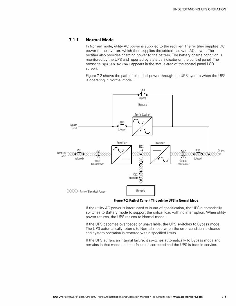
UNDERSTANDING UPS OPERATION
EATON Powerware® 9315 UPS (500–750 kVA) Installation and Operation Manual S 164201691 Rev 1 www.powerware.com 7-3
7.1.1 Normal Mode
In Normal mode, utility AC power is supplied to the rectifier. The rectifier supplies DCpower to the inverter, which then supplies the critical load with AC power. Therectifier also provides charging power to the battery. The battery charge condition ismonitored by the UPS and reported by a status indicator on the control panel. Themessage System Normal appears in the status area of the control panel LCDscreen.
Figure 7-2 shows the path of electrical power through the UPS system when the UPSis operating in Normal mode.
FBP
InputTransformer
Path of Electrical Power Battery
InverterRectifierDCLink
CB2(closed)
OutputTransformer
(closed)
CB3
(closed)
CB1Rectifier
Input
BypassInput (closed)
Output
Static Switch
(open)
CB4
Bypass
Figure 7-2. Path of Current Through the UPS in Normal Mode
If the utility AC power is interrupted or is out of specification, the UPS automaticallyswitches to Battery mode to support the critical load with no interruption. When utilitypower returns, the UPS returns to Normal mode.
If the UPS becomes overloaded or unavailable, the UPS switches to Bypass mode.The UPS automatically returns to Normal mode when the error condition is clearedand system operation is restored within specified limits.
If the UPS suffers an internal failure, it switches automatically to Bypass mode andremains in that mode until the failure is corrected and the UPS is back in service.

UNDERSTANDING UPS OPERATION
EATON Powerware® 9315 UPS (500–750 kVA) Installation and Operation Manual S 164201691 Rev 1 www.powerware.com7-4
7.1.2 Bypass Mode
The UPS automatically switches to Bypass mode if it detects an overload, load fault,or internal failure. The bypass source supplies the commercial AC power to the loaddirectly.
Figure 7-3 shows the path of electrical power through the UPS system when the UPSis operating in Bypass mode.
CAUTIONThe critical load is not protected while the UPS is in Bypass mode.
FBP
InputTransformer
Path of Electrical Power Battery
InverterRectifierDCLink
CB2(open)
OutputTransformer
(open)
CB3
(open)
CB1Rectifier
Input
BypassInput (closed)
Output
Static Switch
(closed)
CB4
Bypass
Figure 7-3. Path of Current Through the UPS in Bypass Mode
The UPS can be transfered from Normal mode to Bypass mode manually. However,the UPS switches automatically to Bypass mode whenever the inverter can no longersupply the critical load. Initially, the static switch fires and conducts power frombreaker FBP to the load. When breaker CB4 closes, the static switch stopsconducting and breaker FBP opens. If the UPS transfers to Bypass mode from Normalmode due to any reason other than operator intervention, the UPS automaticallyattempts to transfer back to Normal mode (up to three times within a ten minuteperiod). The fourth transfer locks the critical load to the bypass source and requiresoperator intervention to transfer.
Bypass mode is a normal operating mode, not an alarm condition. However, if theUPS is unable to return to Normal mode following an automatic transfer to Bypassmode, an alarm condition is recorded.

UNDERSTANDING UPS OPERATION
EATON Powerware® 9315 UPS (500–750 kVA) Installation and Operation Manual S 164201691 Rev 1 www.powerware.com 7-5
7.1.3 Battery Mode
The UPS transfers to Battery mode automatically if a utility power outage occurs, or ifthe utility power does not conform to specified parameters. In Battery mode, thebattery provides emergency DC power that the inverter converts to AC power. Whenthe UPS switches to Battery mode, the alarm indications depend on the cause andcondition of the battery charge. The length of time the system can operate in Batterymode depends on load configuration and battery charge.
Figure 7-4 shows the path of electrical power through the UPS system when the UPSis operating in Battery mode.
FBP
InputTransformer
Path of Electrical Power
InverterRectifierDCLink
CB2(closed)
OutputTransformer
(closed)
CB3
(closed)
CB1Rectifier
Input
BypassInput (open)
Output
Static Switch
(open)
CB4
Bypass
Battery
Figure 7-4. Path of Current Through the UPS in Battery Mode
When the discharging battery voltage reaches the lower limit of UPS operation capability,the critical load transfers to Bypass mode if it is available. If Bypass input is not available, aShutdown Imminent warning occurs. The warning time before critical load loss occurs isapproximately two minutes, depending on load configuration and battery charge.
If incoming power returns to within specified parameters, the UPS automatically returnsto Normal mode and alarm indications clear. However, the process of returning to Normalmode is not instantaneous. The rectifier gradually draws increasing power from theincoming utility until Normal mode is achieved.

UNDERSTANDING UPS OPERATION
EATON Powerware® 9315 UPS (500–750 kVA) Installation and Operation Manual S 164201691 Rev 1 www.powerware.com7-6
This page intentionally left blank.

EATON Powerware® 9315 UPS (500–750 kVA) Installation and Operation Manual S 164201691 Rev 1 www.powerware.com 8-1
Chapter 8 Using the Control Panel
This chapter describes the UPS control panel, including controls and indicators, andhow to monitor UPS operation. The control panel is a black square area on the front ofthe UPS (see Figure 8-1).
Emergency UPM OFFPushbutton Switch
LCD Screen
Pushbutton Switches
Backlit StatusIndicators
Mode Key Switch
Push In To ResetPushbutton Switch
Battery Switch
Figure 8-1. UPS Control Panel
The following sections describe using the UPS control panel to monitor the UPS.See Chapter 9, “UPS Operating Instructions,” for use of the operational controls.
Figure 8Table 8

USING THE CONTROL PANEL
EATON Powerware® 9315 UPS (500–750 kVA) Installation and Operation Manual S 164201691 Rev 1 www.powerware.com8-2
8.1 Using the LCD Screen
The LCD screen at the top of the control panel provides an operator interface with theUPS system. Figure 8-2 identifies the display fields discussed in the followingsections.
Uninterruptible Power System
System NormalALARM: NONENOTICES: NONE
Meters
System
Load Amps
Events Statistics Graphics Setup
Input Output
Bypass Battery
VABnnn
VBC VCA
KWnnn
KVAnnn
IA IB IC
FREQnn.n
PF0.nn
Vnnn
Inn
Meters
nnn
nnn nnn
nnnnnn
VABnnn
VBC VCAnnn nnn
IA IB ICnnn nnnnnn
INnnn
VABnnn
VBC VCAnnn nnn
FREQnn.n
KVAnnn
KWnnn
PF0.nn
Battery
4 MAY 1999 09:25:42
48.6Minutes
Versions+
A
B
C
D
E
F
G
Figure 8-2. LCD Screen
A The UPS status area contains three lines that display the current UPS state. The first line shows the presentUPS operational mode. The second line shows the highest level of the current active alarms, and the third lineshows any notices the UPS has posted. (For more information about alarms and notices, see Chapter 11,“Responding to System Events.”)
B The battery charge box shows the minutes of battery capacity available.
C The menu box shows the currently selected menu and lists the options available on that menu. The title at thetop of the menu box is also shown below on the menu bar (E). Press the and pushbuttons to scroll up anddown through the options in the menu box.
D The currently selected option is highlighted in the menu box (C). Press the and pushbuttons to move thehighlight up or down. The data in the information area (G) changes accordingly.
E The menu bar lists the titles of the menus. The menu title currently displayed in the menu box (C) ishighlighted. When you press the and pushbuttons to move the highlight left or right, the data in the menubox (C) and the information area (G) change accordingly.
F The time stamp shows the current date and time. This date and time are recorded in the Event Log when analarm or notice is activated.
G The information area contains data about UPS status and operation. Select a menu option to display statisticsor graphics.

USING THE CONTROL PANEL
EATON Powerware® 9315 UPS (500–750 kVA) Installation and Operation Manual S 164201691 Rev 1 www.powerware.com 8-3
Use the LCD screen and the pushbuttons beneath it to:
S Monitor UPS operation
S Look at a log of UPS events (alarms, notices, and commands)
8.2 Using the PushbuttonsThe pushbuttons below the LCD screen are labeled with arrows indicating theirfunctions:
Figure 8-3. LCD Pushbuttons
S Press the and pushbuttons to move through the options in a menu, or toscroll through the list of alarms and notices in the Event History Log.
S Press the and pushbuttons to move through the menu titles on the menu bar.Press them simultaneously to silence the horn, or to test the LED lamps behindthe status indicators.
S Press the pushbutton to toggle the use of the and pushbuttons betweenthe menu box and the information area.
8.3 Adjusting the Contrast
Use the pushbuttons to adjust the contrast on the LCD screen. Hold down thepushbutton, then press the pushbutton to increase the contrast or the
pushbutton to decrease the contrast.

USING THE CONTROL PANEL
EATON Powerware® 9315 UPS (500–750 kVA) Installation and Operation Manual S 164201691 Rev 1 www.powerware.com8-4
8.4 Reading the Status Indicators
The six symbols on the left side of the control panel are status indicators. They arebacklit by colored LED lamps, and they work in conjunction with the horn to let youknow the UPS operating status.
Normal This green symbol illuminates when the UPS is operating in Normalmode. The power processing unit (PPU) is supplying power to thecritical load.
Battery This yellow symbol illuminates when the UPS is operating in Batterymode. Because Battery mode is a normal condition of the UPS, theNormal indicator also remains illuminated.
Bypass This yellow symbol illuminates when the UPS is operating in Bypassmode. The critical load is supported by the bypass source. The Normalindicator is not illuminated when the system is in Bypass mode.
Notice This yellow symbol illuminates when the system needs attention. TheLCD screen shows all active notices. Some notices may beaccompanied by a horn. To silence the horn, press the andthe pushbuttons simultaneously. The Notice indicator may beilluminated along with other indicators.
Alarm This red symbol illuminates when a situation requires immediateattention. The LCD screen shows the highest priority active alarms. Allalarms are accompanied by a horn. To silence the horn, press theand the pushbuttons simultaneously. The Alarm indicator may beilluminated along with other indicators.
Standby This yellow symbol illuminates when electricity is present in the PPU ofthe UPS and the Normal indicator is not illuminated. During normalstartup, this indicator illuminates until the the UPS transfers to Normalmode, at which point the Normal indicator illuminates. During normalshutdown, the Standby indicator illuminates until all energy in the UPSis dissipated and shutdown is complete.
For more information about horns, see “System Event Horns” on page 11-1.
To test the LED lamps behind the status indicators, press and hold the andpushbuttons simultaneously for three seconds. All the indicators should illuminateuntil you release the pushbuttons. If any indicator does not illuminate, its LED lampmay need to be replaced. Contact your Eaton service representative if you have aproblem with the indicator lamps.
8.5 Using the Menu Options
The UPS menus allow you to display data in the information area to help you monitorand control UPS operation. The following menus and options are available:
S Meters – Displays performance meters for the system or critical load.
S Events – Displays the list of Active System Events and a historical log ofsystem events.
S Statistics – Displays statistical information about UPS operation for the battery,load, or line.
S Graphics – Displays a real-time graphic representation of the flow of currentthrough the internal UPS components.
S Setup – Allows you to configure the UPS communication port and set the date andtime for the time stamp.

USING THE CONTROL PANEL
EATON Powerware® 9315 UPS (500–750 kVA) Installation and Operation Manual S 164201691 Rev 1 www.powerware.com 8-5
8.5.1 System Meters Screen
Figure 8-4 shows the LCD screen as it appears when you first start the UPS. TheMeters menu is displayed in the menu box, with the System option highlighted. In theinformation area, the system meters show their current readings.
Uninterruptible Power System
System Normal
Meters
System
Load Amps
Events Statistics Graphics Setup
Input Output
Bypass Battery
VABnnn
VBC VCA
KWnnn
KVAnnn
IA IB IC
FREQnn.n
PF0.nn
Vnnn
Inn
Meters
nnn
nnn nnn
nnnnnn
VABnnn
VBC VCAnnn nnn
IA IB ICnnn nnnnnn
INnnn
VABnnn
VBC VCAnnn nnn
FREQnn.n
KVAnnn
KWnnn
PF0.nn
Battery
48.5Minutes
Versions+
ALARM: NONENOTICES: NONE
4 MAY 1999 09:25:42
Figure 8-4. System Meters Screen
The Input area shows the phase-to-phase voltage, frequency, and phase currentof the incoming utility, followed by the kVA, kW, and power factor measurements.The output area shows the same information for the power being output by the UPS.
The Bypass area shows the phase-to-phase voltage of the bypass source. The Batteryarea displays the DC voltage (V) and the DC current (I).

USING THE CONTROL PANEL
EATON Powerware® 9315 UPS (500–750 kVA) Installation and Operation Manual S 164201691 Rev 1 www.powerware.com8-6
8.5.2 Load Amps Meters Screen
Select Load Amps from the Meters menu to view a real-time bar graph of the outputcurrent of the UPS. The graph shows the current for each phase.
Figure 8-5 shows the Load Amps Meters screen.
Uninterruptible Power System
System Normal
Meters
System
Load Amps
Events Statistics Graphics SetupMeters
Output Current
125%
100%
75%
50%
25%
0%Phase A Phase B Phase C
Battery
48.5Minutes
Versions
ALARM: NONENOTICES: NONE
4 MAY 1999 09:25:42
Figure 8-5. Load Amps Meters Screen

USING THE CONTROL PANEL
EATON Powerware® 9315 UPS (500–750 kVA) Installation and Operation Manual S 164201691 Rev 1 www.powerware.com 8-7
8.5.3 Software Versions Screen
Select Versions from the Meters menu to view the software versions installed onthe UPS.
Figure 8-6 shows the Software Versions screen.
Statistics Graphics Setup
Meters
HistoryLoad Amps
Uninterruptible Power System
System Normal
EventsMeters
Software Versions
Part Number
Monitor
Rectifier
Inverter
143650369
143650347
143650348
01.17
*****
*****
Battery
48.5Minutes
Version
System
Versions
ALARM: NONENOTICES: NONE
4 MAY 1999 09:25:42
Figure 8-6. Software Versions Screen

USING THE CONTROL PANEL
EATON Powerware® 9315 UPS (500–750 kVA) Installation and Operation Manual S 164201691 Rev 1 www.powerware.com8-8
8.5.4 Event History Log Screen
Select History from the Events menu to display the Event History Log. The EventHistory Log lists up to 400 system events in chronological order, with the most recentevent listed last. The end of the log (the most recent events) appears when youdisplay the screen; scroll upward to view older event listings.
Figure 8-7 shows the Event History Log screen.
Statistics Graphics Setup
Events
History
Active
Uninterruptible Power System
System Normal
EventsMeters
Event History Log
Event Description
03
03
03
03
03
03
03
16:41:19.3
16:41:20.1
16:41:22.4
16:41:25.5
16:41:26.8
16:41:27.8
16:41:30.4
16:41:29.1
COMMAND: Keyswitch On
STATUS: Auto Mode
COMMAND: Rectifier Commanded On
STATUS: Inverter On
STATUS: Rectifier On
STATUS: Output Breaker (CB3) Closed
STATUS: Bypass Breaker (CB4) Open
03 STATUS: Inverter Normal
Battery
48.5Minutes
Date / TimeMay
ALARM: NONENOTICES: NONE
4 MAY 1999 09:25:42
Figure 8-7. Event History Log Screen
A small return arrow ( ) appears in the upper right corner of the information area ofthe Event History Log screen. This arrow is a reminder that you can press thepushbutton on the control panel to toggle the scroll bar between the menu box andthe information area. When the scroll bar is in the information area, the return arrow isin the menu box. When the scroll bar is in the menu box, the return arrow is in theinformation area.
When the scroll bar is in the information area, you can press the andpushbuttons to scroll through the Event History Log.

USING THE CONTROL PANEL
EATON Powerware® 9315 UPS (500–750 kVA) Installation and Operation Manual S 164201691 Rev 1 www.powerware.com 8-9
8.5.5 Active System Events Screen
Select Active from the Events menu to display a listing of all system events that arecurrently active. The most recent system event is listed first. As events clear, they areremoved from the Active System Events listing.
Figure 8-8 shows the Active System Events screen.
Uninterruptible Power System
ALARM: ON BATTERY SHUTDOWN IMMINENT
Events Statistics Graphics SetupMeters
Events
Active
History
Active System Events
NOTICE: Input power unavailableNOTICE: Bypass Not AvailableALARM: Shutdown Imminent
BatteryMinutes48.5
System Normal
NOTICES: NONE
4 MAY 1999 09:25:42
Figure 8-8. Active System Events Screen

USING THE CONTROL PANEL
EATON Powerware® 9315 UPS (500–750 kVA) Installation and Operation Manual S 164201691 Rev 1 www.powerware.com8-10
8.5.6 Unit Statistics Screen
Select Unit from the Statistics menu to display a listing of statistics about UPSoperation.
Figure 8-9 shows the Unit Statistics screen.
Uninterruptible Power System
UPS System Normal
Events Statistics Graphics SetupMeters
Statistics
Unit
Start Date: 04 MAY 1999
Number of Incidents:
On Battery < 1 Min.On Battery 1-4 Min.On Battery > 4 Min.Full Batt. DischargeBuilding Alarm 1Building Alarm 2Building Alarm 3Building Alarm 4Building Alarm 5Building Alarm 6
UPSBypassBatteryGeneratorLogic
AvailabilityUPSBypass
0100223233
00001198589
0.990.81
48.5MinutesBattery
Month Total DAYS HR MNTime On:
0035 20 590000 00 300000 00 020000 00 000035 21 30
ALARM: NONENOTICES: NONE
4 MAY 1999 09:25:42
Figure 8-9. Unit Statistics Screen
The left column shows the number of UPS incidents for the current month and sincethe start date shown at the top of the information area. The top right column showsthe time that the UPS was on bypass, battery, or generator, and the amount of timethe UPS logic has been functioning since the start date. The lower right columnshows the percent of availability of the UPS and the bypass source.

USING THE CONTROL PANEL
EATON Powerware® 9315 UPS (500–750 kVA) Installation and Operation Manual S 164201691 Rev 1 www.powerware.com 8-11
8.5.7 Mimic Screen
Select Mimic from the Graphics menu to display a real-time graphical representationof the flow of current through the UPS.
Figure 8-10 shows the Mimic screen.
Uninterruptible Power System
UPS System NormalAlarm: NoneNotice: None
Events Statistics Graphics SetupMeters
Graphics
Mimic
CB1 CB3
Rectifier Inverter
Bypass
Battery
100%PercentBattery
CB2
4 MAY 1999 09:25:42
Figure 8-10. Mimic Screen
The Mimic screen shows the internal components of the UPS cabinet. The flow ofcurrent through the components is highlighted.

USING THE CONTROL PANEL
EATON Powerware® 9315 UPS (500–750 kVA) Installation and Operation Manual S 164201691 Rev 1 www.powerware.com8-12
8.5.8 Time Setup Screen
Select Time from the Setup menu to display the Time Setup screen. The Time Setupscreen allows you to set the internal time stamp of the UPS. The time stamp is usedfor logging events in the Event History Log. Figure 8-11 shows the Time Setupscreen.
Statistics Graphics Setup
Setup
Time
Uninterruptible Power System
UPS System Normal
EventsMeters
Port 1
Set Time & Date
DAY DTMON 07
MONAPR
YR99
HR:MN15:06
SAVEYES
Port 2
48.5MinutesBattery
ALARM: NONENOTICES: NONE
Language
4 MAY 1999 09:25:42
Figure 8-11. Time Setup Screen
A small return arrow ( ) appears in the upper right corner of the information area ofthe Time Setup screen. This arrow is a reminder that you can press thepushbutton on the control panel to toggle the scroll bar between the menu box andthe information area. When the scroll bar is in the information area, the return arrow isin the menu box. When the scroll bar is in the menu box, the return arrow is in theinformation area.
When the scroll bar appears in the information area, you can use the pushbuttons tochange the time stamp settings. To change a setting, press the and pushbuttonsto highlight the setting you want to change. To increase the setting (make it a highervalue), press the pushbutton. To decrease the setting (make it a lower value), pressthe pushbutton. To save the settings upon exit from this screen, be sure the Savefield is set to YES.
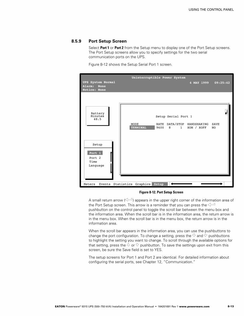
USING THE CONTROL PANEL
EATON Powerware® 9315 UPS (500–750 kVA) Installation and Operation Manual S 164201691 Rev 1 www.powerware.com 8-13
8.5.9 Port Setup Screen
Select Port 1 or Port 2 from the Setup menu to display one of the Port Setup screens.The Port Setup screens allow you to specify settings for the two serialcommunication ports on the UPS.
Figure 8-12 shows the Setup Serial Port 1 screen.
Statistics Graphics Setup
Setup
Port 1
Uninterruptible Power System
UPS System NormalAlarm: NoneNotice: None
EventsMeters
Setup Serial Port 1
RATE9600
DATA/STOP8 1
HANDSHAKINGXON / XOFF
SAVENO
Time
MODETERMINAL
Port 2
48.5MinutesBattery
Language
4 MAY 1999 09:25:42
Figure 8-12. Port Setup Screen
A small return arrow ( ) appears in the upper right corner of the information area ofthe Port Setup screen. This arrow is a reminder that you can press thepushbutton on the control panel to toggle the scroll bar between the menu box andthe information area. When the scroll bar is in the information area, the return arrow isin the menu box. When the scroll bar is in the menu box, the return arrow is in theinformation area.
When the scroll bar appears in the information area, you can use the pushbuttons tochange the port configuration. To change a setting, press the and pushbuttonsto highlight the setting you want to change. To scroll through the available options forthat setting, press the or pushbutton. To save the settings upon exit from thisscreen, be sure the Save field is set to YES.
The setup screens for Port 1 and Port 2 are identical. For detailed information aboutconfiguring the serial ports, see Chapter 12, “Communication.”

USING THE CONTROL PANEL
EATON Powerware® 9315 UPS (500–750 kVA) Installation and Operation Manual S 164201691 Rev 1 www.powerware.com8-14
This page intentionally left blank.

EATON Powerware® 9315 UPS (500–750 kVA) Installation and Operation Manual S 164201691 Rev 1 www.powerware.com 9-1
Chapter 9 UPS Operating Instructions
This chapter describes the UPS controls and instructions for operating the UPSsystem.
NOTE Before starting the UPS, ensure all installation tasks are complete and an authorized Eaton CustomerService Engineer has performed a preliminary startup. The preliminary startup verifies all electricalinterconnections to ensure the installation was successful and the system operates properly.
NOTE The following procedures are applicable for systems with the optional internally installed rectifierinput breaker CB1 and inverter output breaker CB3.
NOTE For System Bypass Module (SBM) operation in a multi-module system, refer to the Powerware 9315Parallel Capacity/Redundant UPS Installation and Operation Manual.
9.1 UPS Controls and Indicators
The controls and indicators identified and described in this section are used to controland monitor UPS operation. Figure 9-1 shows the UPS controls and indicators.
Input/Rectifier Cabinet Output/Inverter Cabinet Module BypassCabinet (MBC)
Control Panel
Input BreakerCB1 (optional)
Output BreakerCB3 (optional)
Backfeed ProtectionBreaker FBP
BypassBreaker CB4
Figure 9-1. UPS Controls and Indicators
Figure 9Table 9

UPS OPERATING INSTRUCTIONS
EATON Powerware® 9315 UPS (500–750 kVA) Installation and Operation Manual S 164201691 Rev 1 www.powerware.com9-2
9.1.1 Control Panel
The UPS control panel contains an LCD screen to display the current UPS systemstatus. You can view a statistical history and log of system events and display areal-time graphic representation of power flowing through the system components.Backlit status indicators show the UPS operating mode and alert you to systemevents.
The control panel is described in Chapter 8, “Using the Control Panel.” The Batteryswitch controls the application of battery power to the UPS. The Mode key switch,also located on this panel, is used to start and stop the system and transfer the loadbetween normal UPS operation and bypass operation. The Emergency UPM Offpushbutton is located at the top of the control panel, and the Push In To Reset buttonfor the Emergency UPM Off is located between the Battery switch and the Mode keyswitch.
9.1.2 UPS Circuit Breakers
The UPS can contain as many as four circuit breakers:
S UPS Input Breaker (CB1)
S UPS Output Breaker (CB3)
S UPS Bypass Breaker (CB4)
S Backfeed Protection Breaker (FBP)
CB1 controls the input to the UPS rectifier, while CB3 controls the output of the UPSinverter. CB1 is optional and may be either motor operated or manually controlled.
CB4 and FBP are used in single module applications and are contained in the MBC ofthe UPS. CB4 is used as the bypass supply in the event the output of the UPS is notavailable and to supply the critical load during maintenance. The FBP is used toprevent power feedback to the UPS input supply when the UPS is operating in theBattery mode. These breakers are electrically controlled by the UPS and are automaticin operation.
Multi-module systems replace the MBC of the UPS with an SBM. Refer to “SBMCircuit Breakers” in the Powerware 9315 Parallel Capacity/Redundant UPS Installationand Operation Manual.
In addition, a remote mounted external battery disconnect is used to connect thebattery string to the UPS. This disconnect is manually controlled.
9.1.3 Emergency UPM Off
An Emergency UPM Off pushbutton is provided for situations where you mustinstantaneously control the UPS output. The pushbutton is located on the front of theUPS for quick access and is covered with a clear plastic shield to prevent accidentalactivation. The shield must be raised before pressing the pushbutton. The EmergencyUPM Off pushbutton is described in Chapter 9, “UPS Operating Instructions.”

UPS OPERATING INSTRUCTIONS
EATON Powerware® 9315 UPS (500–750 kVA) Installation and Operation Manual S 164201691 Rev 1 www.powerware.com 9-3
9.2 Starting the UPS
To start the UPS system:
NOTE This procedure assumes Automode is enabled.
1. Verify that the UPS circuit breakers are set as follows:
UPS Input Breaker (CB1) OPEN
UPS Battery Breaker or Battery Disconnect (CB2) OPEN
UPS Output Breaker (CB3) OPEN
UPS Bypass Breaker (CB4) OPEN
Backfeed Protection Breaker (FBP) OPEN
NOTE When feeder power is applied in Steps 3 and 5, UPS circuit breakers CB1, CB2, CB3, CB4, and FBPwill charge, if not already charged.
2. Ensure the Push In To Reset pushbutton is pressed in.
3. Close the UPS input feeder circuit breaker.
4. Observe the UPS LCD screen becoming active, indicating logic power.
5. Close the UPS Bypass input feeder circuit breaker. Breakers CB4 and FBP closeas soon as charged.
The critical load is immediately supplied by the bypass source. The UPS is inBypass mode, until the inverter turns on and the UPS transfers to Normal mode.The status indicator on the UPS control panel indicates the UPS is in Bypassmode.
6. On the UPS, set the Battery switch to ENABLE.
7. If system is equipped with motor operated breaker CB1, proceed to Step 8;otherwise, proceed to Step 11.
8. On the UPS, turn the Mode key switch to NORMAL for one second.
NOTE If system is equipped with Inrush Protection Option, the inrush contactor closes before UPSbreaker CB1 closes.
9. Confirm UPS breaker CB1 has closed by viewing the breaker position on the LCDMimic screen.
The rectifier and the input/rectifier cooling blowers turn on.
10. Proceed to Step 13.
11. Close UPS breaker CB1.
The input/rectifier cooling blowers turn on.
12. On the UPS, turn the Mode key switch to NORMAL for one second.
The rectifier turns on.
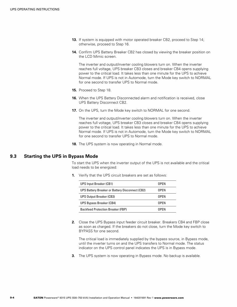
UPS OPERATING INSTRUCTIONS
EATON Powerware® 9315 UPS (500–750 kVA) Installation and Operation Manual S 164201691 Rev 1 www.powerware.com9-4
13. If system is equipped with motor operated breaker CB2, proceed to Step 14;otherwise, proceed to Step 16.
14. Confirm UPS Battery Breaker CB2 has closed by viewing the breaker position onthe LCD Mimic screen.
The inverter and output/inverter cooling blowers turn on. When the inverterreaches full voltage, UPS breaker CB3 closes and breaker CB4 opens supplyingpower to the critical load. It takes less than one minute for the UPS to achieveNormal mode. If UPS is not in Automode, turn the Mode key switch to NORMALfor one second to transfer UPS to Normal mode.
15. Proceed to Step 18.
16. When the UPS Battery Disconnected alarm and notification is received, closeUPS Battery Disconnect CB2.
17. On the UPS, turn the Mode key switch to NORMAL for one second.
The inverter and output/inverter cooling blowers turn on. When the inverterreaches full voltage, UPS breaker CB3 closes and breaker CB4 opens supplyingpower to the critical load. It takes less than one minute for the UPS to achieveNormal mode. If UPS is not in Automode, turn the Mode key switch to NORMALfor one second to transfer UPS to Normal mode.
18. The UPS system is now operating in Normal mode.
9.3 Starting the UPS in Bypass Mode
To start the UPS when the inverter output of the UPS is not available and the criticalload needs to be energized:
1. Verify that the UPS circuit breakers are set as follows:
UPS Input Breaker (CB1) OPEN
UPS Battery Breaker or Battery Disconnect (CB2) OPEN
UPS Output Breaker (CB3) OPEN
UPS Bypass Breaker (CB4) OPEN
Backfeed Protection Breaker (FBP) OPEN
2. Close the UPS Bypass input feeder circuit breaker. Breakers CB4 and FBP closeas soon as charged. If the breakers do not close, turn the Mode key switch toBYPASS for one second.
The critical load is immediately supplied by the bypass source, in Bypass mode,until the inverter turns on and the UPS transfers to Normal mode. The statusindicator on the UPS control panel indicates the UPS is in Bypass mode.
3. The UPS system is now operating in Bypass mode. No backup is available.

UPS OPERATING INSTRUCTIONS
EATON Powerware® 9315 UPS (500–750 kVA) Installation and Operation Manual S 164201691 Rev 1 www.powerware.com 9-5
9.4 Transferring to Bypass Mode
NOTE In the following step, holding the Mode key switch in the BYPASS position for three secondstransfers the load to Bypass and shuts down the UPS.
To transfer the critical load to Bypass mode:
1. On the UPS, turn the Mode key switch to BYPASS for one second.
2. Confirm UPS breaker CB4 closes and UPS breaker CB3 opens.
The UPS switches to Bypass mode. If the bypass source is not available, thepower processor remains on and an alarm sounds.
3. On the UPS LCD screen, verify that the On Bypass message appears and theBypass Mode indicator illuminates on the control panel. The UPS system isnow on bypass and UPS power processor remains on.
WARNINGPower is present inside Input/Rectifier and Output/Inverter cabinets.
9.5 Transferring to Normal Mode
To transfer the critical load to Normal mdoe:
1. On the UPS, turn the Mode key switch to NORMAL for one second.
2. Confirm UPS breaker CB3 closes and UPS breaker CB4 opens.
The UPS switches to Normal mode. If the power processor unit is not available,the system remains on bypass and an alarm sounds.
3. On the UPS LCD screen, verify that the Normal message appears and theNormal Mode indicator illuminates on the control panel. The UPS system is nowin Normal mode.

UPS OPERATING INSTRUCTIONS
EATON Powerware® 9315 UPS (500–750 kVA) Installation and Operation Manual S 164201691 Rev 1 www.powerware.com9-6
9.6 Transferring to Bypass and Shutting Down the UPS
To transfer the critical load to Bypass mode and shut down the UPS:
1. On the UPS, turn the Mode key switch to BYPASS for one second.
2. Confirm UPS breaker CB4 closes and UPS breaker CB3 opens.
The UPS switches to Bypass mode. If the bypass source is not available, thepower processor unit remains on and an alarm sounds.
3. On the UPS LCD screen, verify that the On Bypass message appears and theBYPASS Mode indicator illuminates on the control panel. The UPS system is nowon bypass.
4. On the UPS, turn the Mode key switch to BYPASS for one second.
5. Observe that UPS breaker CB1 and Battery Disconnect CB2 open.
The bypass source supplies the critical load, the power processor unitde-energizes and cooling blowers shutdown.
WARNINGPower is present at the UPS breaker CB1 input, until the upstream UPS input feeder circuit breaker isopened.
9.7 Shutting Down the UPS and Critical Load
To perform maintenance or service on the critical load, shut down power to the load:
1. Transfer the critical load to bypass by performing the procedure in paragraph 9.4.
2. Turn off all equipment that is being powered by the UPS.
3. Press the Emergency UPM Off pushbutton on the control panel.
WARNINGPower is present at the UPS breaker CB1 input, until the upstream UPS input feeder circuit breaker isopened.
4. Open the UPS input feeder circuit breaker.
9.8 Using the UPS Emergency UPM Off Pushbutton
Initiate a UPS Emergency UPM Off using the covered, red Emergency UPM Offpushbutton on the UPS control panel. This pushbutton is protected by a clear plasticshield to prevent accidental activation. In an emergency, you can press thispushbutton to instantaneously control the UPS output. The UPS Emergency UPM Offpushbutton functions differently, depending on the Emergency Power-off optionspecified when ordered. The options available are as follows:
S Power to the critical load is de-energized and the UPS powered down. UPSbreakers CB1, CB3, FBP, and Battery Disconnect CB2 trip, and the UPS is cut offfrom utility power.
S The critical load is transferred to bypass and the UPS powered down. UPSbreakers CB1, CB3, and Battery Disconnect CB2 trip, and the UPS is cut off fromutility power.

UPS OPERATING INSTRUCTIONS
EATON Powerware® 9315 UPS (500–750 kVA) Installation and Operation Manual S 164201691 Rev 1 www.powerware.com 9-7
The UPS (including Bypass) remains locked off until you reset the Emergency UPMOff pushbutton.
To restart the UPS after pressing the Emergency UPM Off pushbutton, follow theprocedure in paragraph 9.8.2, “Resetting the UPS System after an Emergency UPMOff,” before starting the system.
NOTE The remote emergency power-off (REPO) option functions the same way as the Emergency UPM Offpushbutton on the UPS control panel.
9.8.1 Using the UPS Emergency UPM Off Pushbutton
1. Raise the clear plastic shield covering the red UPS Emergency UPM Offpushbutton on the UPS control panel.
2. Press the Emergency UPM Off pushbutton.
The breakers open (you can hear them opening) and the Push In To Resetpushbutton on the UPS control panel pops out.
9.8.2 Resetting the UPS System after an Emergency UPM Off
CAUTIONDo not attempt to restart the system after Emergency UPM Off until the cause of the emergency has beenidentified and cleared.
The Push In To Reset pushbutton is a small white button on the UPS control panel.The Push In To Reset pushbutton pops out when the Emergency UPM Offpushbutton on the UPS control panel is activated.
To reset the UPS system:
1. Press the Push In To Reset pushbutton until it clicks in and remains recessed.
2. Breakers CB4 and FBP charge and close.
3. Reset tripped circuit breakers on UPS systems with manually controlled CB1 andCB2 breakers.
4. The UPS system is now reset. To restart the UPS system, see “Starting theUPS” on page 9-3.

UPS OPERATING INSTRUCTIONS
EATON Powerware® 9315 UPS (500–750 kVA) Installation and Operation Manual S 164201691 Rev 1 www.powerware.com9-8
This page intentionally left blank.

EATON Powerware® 9315 UPS (500–750 kVA) Installation and Operation Manual S 164201691 Rev 1 www.powerware.com 10-1
Chapter 10 Using Features and Options
The many standard features of your UPS system provide consistent, economical, anddependable power protection. In addition, you can add available options to enhancethe performance of your system. This chapter provides descriptions of some of thefeatures and options introduced earlier in this manual. For the customer interfacepanel and terminal locations and for terminal wiring information, see:
S Paragraph A.3 starting on page A-12
S Paragraph A.4 starting on page A-22
S Paragraph A.5 starting on page A-28
10.1 Building Alarm Monitoring
This standard feature lets you connect the UPS to building alarms, such as smokedetectors or overtemperature alarms. The customer interface terminals for externalconnections are located inside the UPS.
Regardless of how you assign the building alarms, the default is to display the alarmsas Building Alarm 1, Building Alarm 2, Building Alarm 3, and so on, on the UPS controlpanel. Use twisted-pair wires for each alarm input and common.
10.2 General Purpose Relay Contacts
Two general purpose relay contacts are provided as a standard feature on the UPS.The alarm contacts (one notice and one alarm) are located inside the UPS on thecustomer interface terminal board.
You can specify that each contact be either normally-closed (NC) or normally-open(NO). If the state of the contact changes from the state you specify as normal, asignal is issued. You can connect these contacts to equipment at your facility (such asa light or an alarm bell) to let you know when an alarm is active on the UPS. Thisfeature is useful if the UPS is located in a remote area where the UPS horn may notbe heard immediately.
CAUTIONContacts should not be operated in excess of 30 Vac or 42.4V peak AC or DC @ 1A maximum.
Figure 10Table 10

USING FEATURES AND OPTIONS
EATON Powerware® 9315 UPS (500–750 kVA) Installation and Operation Manual S 164201691 Rev 1 www.powerware.com10-2
10.3 Optional Remote Monitor Panel
The optional Remote Monitor Panel (RMP) monitors the UPS system operating statusand alarm condition from virtually any location within your facility, up to152.4m (500 ft) from the UPS. You can flush-mount or surface-mount an RMP on adesktop, wall, or wherever you have a serial interface line. Figure 10-1 shows anRMP.
Figure 10-1. RMP

USING FEATURES AND OPTIONS
EATON Powerware® 9315 UPS (500–750 kVA) Installation and Operation Manual S 164201691 Rev 1 www.powerware.com 10-3
The RMP contains a local horn and the following backlit status indicators:
SYSTEM NORMALThe UPS is energized (either with utility power or battery backup) and issupplying conditioned power to the critical load.
NO REDUNDANCYThis indicator applies only to parallel systems when one cabinet is notfunctioning. This feature is not available on this system.
ON GENERATOR
This alarm means that the UPS input and bypass are being supplied by thepower from the generator, instead of from the utility power.
ON BYPASSThe bypass source is supplying the critical load. Usually this means thatthe UPS is not energized. The load is not protected in Bypass mode, and ahorn sounds after 30 seconds.
UPS ALARMThe UPS system is issuing an alarm. Conditions that affect the current UPSmode are indicated by the indicators and horn on the UPS.
ON BATTERYThe UPS battery backup is supplying the critical load. The utility power iseither interrupted or out of specification. The SYSTEM NORMAL indicatoris also lit.
BYPASS UNAVAILABLEThe UPS system is in Normal mode, but a bypass source is not withinspecification. A horn sounds after 30 seconds.
SHUTDOWN IMMINENTThe UPS is preparing to shut down because the UPS is in Battery modeand the DC voltage is approaching its low limit.This indicator is accompanied by a horn.

USING FEATURES AND OPTIONS
EATON Powerware® 9315 UPS (500–750 kVA) Installation and Operation Manual S 164201691 Rev 1 www.powerware.com10-4
10.4 Optional Relay Interface Module
The optional Relay Interface Module (RIM) uses relay contact closures to indicate theoperating status and alarm condition of the Parallel Capacity/Redundant system.Figure 10-2 shows the RIM with its four 15-pin connectors labeled J1 through J4.
Figure 10-2. RIM
The RIM can provide the following signals:
UPS AVAILABLE Pins 1 and 12 Contacts are closed when the UPS is offline.
UPS OFF LINE Pins 3 and 13 Contacts are closed when the UPS is operating in Normalmode.
BATTERY WEAK Pins 5 and 14 Contacts are closed when approximately two minutes ofbattery time is remaining, before the critical load is lost.
UTILITY FAILURE Pins 6 and 15 Contacts are closed when Utility Failure is detected.

USING FEATURES AND OPTIONS
EATON Powerware® 9315 UPS (500–750 kVA) Installation and Operation Manual S 164201691 Rev 1 www.powerware.com 10-5
10.5 Optional Supervisory Contact Module
An optional Supervisory Contact Module (SCM) establishes an interface between theParallel Capacity/Redundant system manufacturer’s equipment and the customer’smonitor. This interface allows the customer to monitor operational status of theParallel Capacity/Redundant system equipment. Figure 10-3 shows the SCM, inputconnections on TB1, and output connections on TB2.
TB2
Figure 10-3. SCM
The SCM provides signals for the following indications:
SYSTEM NORMAL TB2-1 through TB2-3
NO REDUNDANCY TB2-4 through TB2-6
ON GENERATOR TB2-7 through TB2-9
BYPASS NOT AVAILABLE TB2-10 through TB2-12
ON BATTERY TB2-13 through TB2-15
UPS ALARM TB2-16 through TB2-18
ON BYPASS TB2-19 through TB2-21
SHUTDOWN IMMINENT TB2-22 through TB2-24

USING FEATURES AND OPTIONS
EATON Powerware® 9315 UPS (500–750 kVA) Installation and Operation Manual S 164201691 Rev 1 www.powerware.com10-6
This page intentionally left blank.

EATON Powerware® 9315 UPS (500–750 kVA) Installation and Operation Manual S 164201691 Rev 1 www.powerware.com 11-1
Chapter 11 Responding to System Events
When the UPS system is operating in Normal mode, it continually monitors itself andthe incoming utility power. In Battery or Bypass modes, the UPS may issue alarms tolet you know exactly what event caused the change from Normal mode. Systemevents on the UPS can be indicated by horns, indicators, messages, or all three.
Select Active from the Events menu on the LCD screen to display the Active SystemEvents screen. This screen shows any currently active alarms, notices, or commands.
11.1 System Event Horns
The system event horn beeps according to the type of event it is signifying:
S When the UPS detects an alarm that requires your attention, the horn beeps athalf-second intervals.
S When a notice occurs, the horn beeps at two-second intervals.
11.2 System Event Indicators
The status indicators on the UPS control panel work in conjunction with the horn tolet you know when the UPS system is operating in any mode other than Normalmode. Only the Normal indicator is illuminated during normal UPS system operation.The others illuminate to indicate alarms or events. When an alarm occurs, first checkthese indicators to see what type of event has taken place. For descriptions of thestatus indicators, see paragraph 8.4 on page 8-4.
11.3 System Event Messages
When a system event occurs, a message is added to the Event History Log. Amessage may also appear on the UPS control panel. The Event History Log containsall system event messages, whether or not they were displayed on the control panel.
Figure 11Table 11

RESPONDING TO SYSTEM EVENTS
EATON Powerware® 9315 UPS (500–750 kVA) Installation and Operation Manual S 164201691 Rev 1 www.powerware.com11-2
This page intentionally left blank.

EATON Powerware® 9315 UPS (500–750 kVA) Installation and Operation Manual S 164201691 Rev 1 www.powerware.com 12-1
Chapter 12 Communication
This chapter describes the communication features of the Powerware 9315 UPS andprovides information about connecting hardware, configuring the ports, changingsettings, and changing modes.
12.1 Locating the Customer Interface Panel
The customer interface panel inside the UPS contains:
S Two serial communication ports, one DB-9 and one DB-25.
The ports provide a computer interface to a Remote Monitor Panel (RMP), RelayInterface Module (RIM), Supervisory Contact Module (SCM), or remote terminaland/or printer.
S A 120 Vac, 0.2A convenience outlet for powering a modem used for remotenotification.
S An X-Slot communication bay for installing an optional X-Slot card.
See Appendix A for the UPS customer interface panel location.
12.2 Connecting Equipment to a Serial Port
The UPS serial communication ports are designed to accept a wide variety of datacommunication equipment (DCE), such as terminals, printers, and computers. Use anappropriate cable for the type of equipment you are connecting to the UPS. Cablesshould be no longer than 16m (50 ft) and have a male connector.
Port 1 cable pins are identified in Figure 12-1 and the pin functions are described inTable 12-1. Port 2 cable pins are identified in Figure 12-2 and the pin functions aredescribed in Table 12-2.
NOT USED
485–
485+
RETURN
7
8
9
1
5
4
3
2
+24VRS-232 TXD
RS-232 RXDNOT USED
RETURN
6
Figure 12-1. Port 1 (DB-9)
Table 12-1. Pin Assignments for Port 1 (DB-9)
Pin Number Symbol Function Comments
1 +24V +24 Volts DC
2 TXD Transmit Data Input to UPS
3 RXD Receive Data Output from UPS
5 RTN Return
7 485+ RS-485 + Data
8 485– RS-485 – Data
9 RTN Return
Figure 12Table 12

COMMUNICATION
EATON Powerware® 9315 UPS (500–750 kVA) Installation and Operation Manual S 164201691 Rev 1 www.powerware.com12-2
13
12
10
11
9
NOT USED
NOT USED
NOT USED
NOT USED
NOT USED
NOT USED
RS-232 DTR
NOT USED
–12V
NOT USED
NOT USED
NOT USED
23
21
19
17
15
1
5
4
3
2
GND
RS-232 TXD
RS-232 RXD
RS-232 RTS
RS-232 CTS
6
8
7
RS-232 DSR
RTN
+12V
NOT USED
NOT USED
NOT USED
NOT USED
NOT USED
24
22
25
20
18
16
14
Figure 12-2. Port 2 (DB-25)
Table 12-2. Pin Assignments for Port 2 (DB-25)
Pin Number Symbol Function Comments
1 GND Chassis Ground
2 TXD Transmit Data Input to UPS
3 RXD Receive Data Output from UPS
4 RTS Request to Send Input to UPS
5 CTS Clear to Send Output from UPS
6 DSR Data Set Ready Output from UPS
7 RTN Return
8 +12V +12 Volts Output from UPS - always true
20 DTR Data Terminal Ready Input to UPS - typically not used by UPS
22 –12V –12 Volts Output from UPS - always true
NOTE Pins 5 and 6 are tied together internally.

COMMUNICATION
EATON Powerware® 9315 UPS (500–750 kVA) Installation and Operation Manual S 164201691 Rev 1 www.powerware.com 12-3
12.3 Configuring the Serial Ports
Configure the communication port using the LCD screen and pushbuttons on the UPScontrol panel.
Select Port 1 or Port 2 from the Setup menu to display one of the Setup Port screens.The screens for Port 1 and Port 2 are identical, and allow you to specify settings forthe two serial communication ports. Figure 12-3 shows the Setup Serial Port 1screen.
Statistics Graphics Setup
Setup
Port 1
Uninterruptible Power System
UPS System Normal
EventsMeters
Setup Serial Port 1
Rate9600
Data/Stop8 1
HandshakingXON / XOFF
SaveNO
Time
ModeTERMINAL
Port 2
Battery
100%Percent
ALARM: NONENOTICES: NONE
15 JUL 1998 09:25:42
Figure 12-3. Setup Serial Port 1 Screen
A small return arrow ( ) appears in the upper right corner of the Setup Port screen.This arrow is a reminder that you can press the pushbutton on the control panelto toggle the pushbuttons between the menu box and the information area.
If the scroll bar is in the menu box, press the pushbutton to toggle to theinformation area. The first setting (Mode) is highlighted. Press the or pushbuttonto move the highlight to the setting you want to change. To scroll through theavailable options for that setting, press the or pushbutton.
To save the settings upon exit from this screen, be sure the Save field is set to YES.
Table 12-3 shows which options are available for each port. The sections that followdescribe the configuration settings you can change.

COMMUNICATION
EATON Powerware® 9315 UPS (500–750 kVA) Installation and Operation Manual S 164201691 Rev 1 www.powerware.com12-4
Table 12-3. Options Available for Each Communication Port
Port 1 Port 2 Options
X X Terminal Mode
X X System Configuration Mode
X Calibration Mode
X Computer Mode
X Remote Monitor Mode
X X Baud rate of 300, 1200, 2400, 4800, 9600, or 19200
X X Data size/stop bits of 8/1 or 8/2
X Data size/stop bits of 7/1 or 7/2
X X Disabled handshaking
X X XON/XOFF handshaking
12.3.1 Modes
Each communication port operates in one of the following modes:
S Terminal Mode – System events are logged immediately as they occur.
S System Configuration Mode – Allows you to set building alarms, battery tests, andother UPS functions. (Check with your sales or service representative foravailability.)
S Calibration Mode – Used only by service personnel; available for Port 2 only.
S Computer Mode – Provides an Eaton proprietary Binary Computer Mode (BCM)Interface facility monitoring or network communication via a Powerware.ConnectUPS Card. Available for Port 2 only.
S Remote Monitor Mode – Sends all system event information to an RMP, RIM, orSCM; available for Port 1 only.
Port 1 and Port 2 cannot be in the same mode simultaneously; they must always beoperating in different modes. The modes are described later in this chapter.
12.3.2 Rate
The baud rate determines the speed of data transferred between the UPS and theconnected equipment. For Remote Monitor mode, the baud rate must be set to 300.All other modes should operate at the highest baud rate available with the connectedequipment.
You can select a baud rate of 300, 1200, 2400, 4800, 9600, or 19200.
NOTE 300 baud is not recommended for any mode except Remote Monitor.

COMMUNICATION
EATON Powerware® 9315 UPS (500–750 kVA) Installation and Operation Manual S 164201691 Rev 1 www.powerware.com 12-5
12.3.3 Data/Stop
The data size and stop bits of the equipment connected to this port determine thenumber of bits transmitted per ASCII character. The data size and stop bits youspecify depend on the configuration of your equipment.
For Port 1, the data size must be set to 8, with 1 or 2 stop bits. Settings of 7 databits/1 stop bit and 7 data bits/2 stop bits are available for Port 2.
NOTE When connecting a computer running a terminal emulation program, set your equipment to NOPARITY.
12.3.4 Handshaking
This setting controls handshaking. You can select XON/XOFF or Disabled for thissetting.
S XON/XOFF – If handshaking is enabled, the UPS uses special characters (XON andXOFF) to handshake with the host terminal. The XON character is defined to beASCII value 11 hex, and the XOFF character is defined to be ASCII value 13 hex.Upon reception of an XOFF command, the UPS halts transmission until an XONcommand is received. In the same way, if the terminal receives an XOFFcommand, the UPS expects the terminal to halt transmission until the UPSsends an XON command.
S Disabled (No Handshaking) – If handshaking is disabled, the UPS transmits andreceives data via the serial port, ignoring all inputs from handshaking lines.
12.3.5 Save
Set to YES to save any changes to configuration settings upon exit from the Setupscreen. Set to NO if you do not want to save any changes.
12.3.6 Default Settings
The following are the default configuration settings for the serial communicationports:
Port 1 Remote Monitor 300 baud 8/1 Handshaking Disabled
Port 2 Terminal 9600 baud 8/1 Handshaking Disabled
Each communication port on the UPS operates in one of five modes that you selectwhen configuring the port using the Setup Port screen.
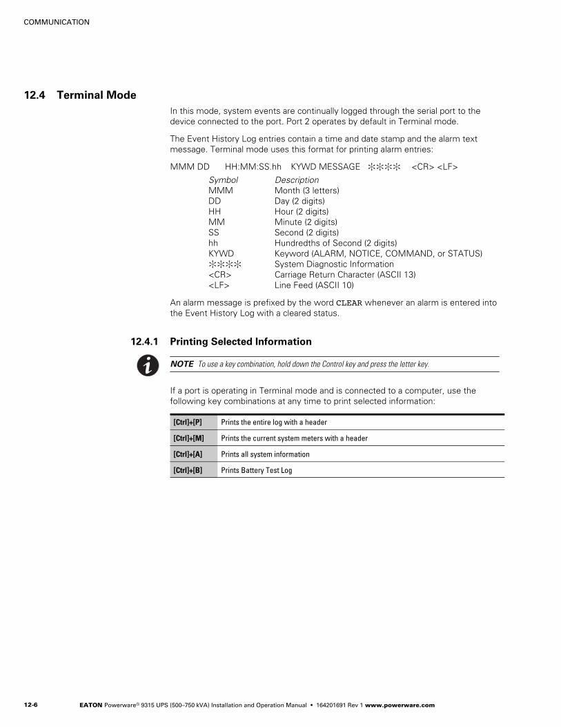
COMMUNICATION
EATON Powerware® 9315 UPS (500–750 kVA) Installation and Operation Manual S 164201691 Rev 1 www.powerware.com12-6
12.4 Terminal Mode
In this mode, system events are continually logged through the serial port to thedevice connected to the port. Port 2 operates by default in Terminal mode.
The Event History Log entries contain a time and date stamp and the alarm textmessage. Terminal mode uses this format for printing alarm entries:
MMM DD HH:MM:SS.hh KYWD MESSAGE :::: <CR> <LF>
Symbol DescriptionMMM Month (3 letters)DD Day (2 digits)HH Hour (2 digits)MM Minute (2 digits)SS Second (2 digits)hh Hundredths of Second (2 digits)KYWD Keyword (ALARM, NOTICE, COMMAND, or STATUS):::: System Diagnostic Information<CR> Carriage Return Character (ASCII 13)<LF> Line Feed (ASCII 10)
An alarm message is prefixed by the word CLEAR whenever an alarm is entered intothe Event History Log with a cleared status.
12.4.1 Printing Selected Information
NOTE To use a key combination, hold down the Control key and press the letter key.
If a port is operating in Terminal mode and is connected to a computer, use thefollowing key combinations at any time to print selected information:
[Ctrl]+[P] Prints the entire log with a header
[Ctrl]+[M] Prints the current system meters with a header
[Ctrl]+[A] Prints all system information
[Ctrl]+[B] Prints Battery Test Log

COMMUNICATION
EATON Powerware® 9315 UPS (500–750 kVA) Installation and Operation Manual S 164201691 Rev 1 www.powerware.com 12-7
12.4.2 Entire Log [Ctrl]+[P]
The [Ctrl]+[P] key sequence prints the entire UPS Event History Log at the time thedata is requested. The printout begins with the oldest alarm entry in the queue andends with the most recent. Any alarms that occur while the Event History Log isprinting are included in chronological order. The Event History Log lists upto 400 system events. Figure 12-4 shows a sample Event History Log printout.
Event History Log
Event Description
MAY 1212121212121212
JUN 04
16:41:19.316:41:29.116:41:42.416:42:05.516:42:46.816:43:15.816:43:42.416:44:29.1
12:16:35.9
COMMAND: Keyswitch OnSTATUS: Auto ModeCOMMAND: Rectifier Commanded OnSTATUS: Inverter OnSTATUS: Rectifier OnSTATUS: Inverter Contactor (3) ClosedSTATUS: Bypass Contactor (K4) Open
NOTICE: Room High Temperature
Uninterruptible Power System
UPS System NormalAlarm: NoneNotice: None
03 NOV 1997 14:23:45
STATUS: Inverter Normal
04211000
20302202
324001
Figure 12-4. Event History Log

COMMUNICATION
EATON Powerware® 9315 UPS (500–750 kVA) Installation and Operation Manual S 164201691 Rev 1 www.powerware.com12-8
12.4.3 Meters Printout [Ctrl]+[M]
The [Ctrl]+[M] key sequence prints the current readings of the UPS system meters.The Input area shows the phase-to-phase voltage, frequency, and phase current ofthe incoming utility, followed by the kVA, kW, and power factor measurements. Theoutput area shows the same information for the power being output by the UPS. TheBypass area shows the phase-to-phase voltage of the bypass source. The Batteryarea displays the DC voltage (V) and the DC current (I). Figure 12-5 shows a sampleSystem Meters printout.
Input Output
Bypass Battery
VAB480
VBC VCA
KW505
KVA530
IA IB IC
FREQ60.0
PF0.95
V540
I0
640
480 480
640640
VAB480
VBC VCA480 480
IA IB IC480 480480
IN0
VAB480
VBC VCA480 480
FREQ60.0
KVA400
KW320
PF0.80
Uninterruptible Power System
UPS System NormalAlarm: NoneNotice: None
03 NOV 1997 14:22:45
+
Figure 12-5. System Meters Screen
12.4.4 System Information Printout [Ctrl]+[A]
The [Ctrl]+[A] key sequence prints a listing of all available serial data. This printoutcontains the information shown on the Event History Log and System Meters screensof the UPS (see Figure 12-4 and Figure 12-5).

COMMUNICATION
EATON Powerware® 9315 UPS (500–750 kVA) Installation and Operation Manual S 164201691 Rev 1 www.powerware.com 12-9
12.5 System Configuration Mode
The System Configuration mode allows you to modify special functions in your UPS.These functions include programming of building alarms, customizing building alarmmessages, adjusting the nominal output voltage, and scheduling battery tests. Themenus provided and their function are described in the following sections.
12.5.1 System Configuration Mode Main Menu
When the System Configuration mode is selected with a terminal attached, you areprompted to enter the password for this mode:
Please Enter Password:
The default password is POWER1. You may modify this password using the changepassword function in the following menu. When the valid password is entered, theMain menu is displayed:
Program Mode Main Menu
1. Program Building Alarms2. Program Unit Name3. Adjust Output Voltage4. Change Password5. Battery Test Setup6. Modify Low Battery Time7. Exit Program Mode
Enter Selection:
12.5.2 Program Building Alarms
This menu provides access to all the functions available in the System Configurationmode. If 1 is entered at the prompt, you can program the building alarm functions:
Program Building Alarms
1. Enable/Disable Default Functions2. Customize Alarm Messages3. Return to Main Menu
Enter Selection:
12.5.3 Enable/Disable Default Functions
From this menu you may either enable the building alarms for general functions orspecial functions, such as On Generator, Go To Bypass, and Go To UPS. You mayalso customize the alarm messages from this menu. When 1 is selected, thefollowing menu is displayed:
Enable/Disable Default Functions
1. Enable/Disable Go To Bypass2. Enable/Disable Go To UPS3. Enable/Disable On Generator4. Enable/Disable Building Alarm5. Return to Program Building Alarms Menu
Enter Selection:

COMMUNICATION
EATON Powerware® 9315 UPS (500–750 kVA) Installation and Operation Manual S 164201691 Rev 1 www.powerware.com12-10
If you select 1, 2, or 3 from this menu, the following menu is displayed:
Enable/Disable (Function)
Enabled Building Alarm Number(s) 1 4
Enter E# to Enable Building Alarm Number #
Enter D# to Disable Building Alarm Number #
Enter <CR> for No Change
Enter Selection:
Where (Function) indicates the function the building alarm is being programmed for.The text following the “Enabled Building Alarm Number(s)” label indicates whichbuilding alarms are currently enabled for the function. In this example, BuildingAlarms 1 and 4 are enabled. A building alarm can only be programmed for one specialfunction at a time from these menus. Enabling a building alarm for a special functionautomatically enables the alarm. If you disable a special function, the building alarm isalso disabled.
If you select entry 4 from this menu, the following menu is displayed:
Enable/Disable Building Alarm
Enabled Building Alarm Number(s) 1 4
Enter E# to Enable Building Alarm Number #
Enter D# to Disable Building Alarm Number #
Enter <CR> for No Change
Enter Selection:
The text following the “Enabled Building Alarm Number(s)” label indicates whichbuilding alarms are currently enabled. In this example, Building Alarms 1 and 4 areenabled.
12.5.4 Customize Alarm Messages
If Customize Alarm Message (option 2) is selected from the Program Building Alarmsmenu, you can select a custom message for a building alarm or disable a previouslyenabled building alarm custom message. When this entry is selected, the followingmenu is displayed:
Customize Alarm Messages
Enabled on Building Alarm Number(s) 2 3
Enter Building Alarm Number:
This example indicates that there are custom messages enabled for Building Alarms 2and 3. When a building alarm number is entered, the message being used by thesoftware is displayed (either a custom message or the default message indicated bythe list of enabled custom messages). If 1 was entered at the prompt, the following isdisplayed:
Building Alarm Active Message: Building Alarm 1 (defaultmessage)
Enter New Message or <CR> for No Change:

COMMUNICATION
EATON Powerware® 9315 UPS (500–750 kVA) Installation and Operation Manual S 164201691 Rev 1 www.powerware.com 12-11
At this level you can enter a custom message, 30 characters maximum, to displaywhen Building Alarm 1 is activated. If a custom message is entered to activate thebuilding alarm, a custom message should also be entered to deactivate the buildingalarm. After the message or a carriage return is entered, the following is displayed:
Building Alarm Clear Message: Clear Building Alarm 1 (defaultmessage)
Enter New Message or <CR> for No Change:
At this prompt, the user should enter the custom message for the building alarmdeactivation state. When a message or a carriage return is entered, the following isdisplayed:
Enter E to Enable Custom Message
Enter D to Disable Custom Message
Enter <CR> for No Change
Enter Selection:
If E is entered at the prompt, the custom messages are used for the building alarm. IfD is entered, the default messages are used for the building alarm.
12.5.5 Program Unit Name
If Program Unit Name (option 2) is selected from the Main menu (see page 12-9), thefollowing is displayed:
Program Unit Name
Unit Name:
Enter New Name or <CR> No Change:
NOTE The Unit Name is 45 characters maximum, including spaces and punctuation.
NOTE If the user wants to center the text portion of the name, the appropriate number of leading spacesshould be included when entered.
The current Unit Name is displayed. This name is displayed on the second line of thedisplay and in the headers of printouts from Terminal mode. If a change is desired,the new Unit Name should be entered at the prompt.
12.5.6 Change Password
If Change Password (option 4) is selected from the Main menu (see page 12-9), thefollowing menu is displayed:
Change Password
Enter New Password:
Verify New Password:
<CR> to return with no change.
NOTE The password must be six characters in length.
The password is changed if the user enters and verifies a new password.

COMMUNICATION
EATON Powerware® 9315 UPS (500–750 kVA) Installation and Operation Manual S 164201691 Rev 1 www.powerware.com12-12
12.5.7 Battery Test Setup
If Battery Test Setup (option 5) is selected from the Main menu (see page 12-9), thefollowing menu is displayed:
NOTE If a message stating “Battery Test Requires Calibration” appears, please notify your Eaton servicerepresentative for proper calibration.
Battery Test Setup
1. Setup One-time Delayed Battery Test2. Setup Monthly Battery Test3. Setup Quarterly Battery Test4. Cancel Pending Battery Test5. Display Next Scheduled Battery Test6. Return to Main Menu
Enter Selection:
This menu allows you to schedule battery tests, review scheduled battery tests, orcancel pending battery tests. If you select 1, 2, or 3 from this menu, the followingmenu is displayed:
Enter Starting Month (1–12):
Enter Day of Week, Sunday = 1, (1–7):
Enter Week of Month (1–5):
Enter Hour of Test (0–23):
Enter Minute of Test (0–59):
<CR> with no entry will return to Battery Test Setup Menu.
NOTE Follow each entry with a carriage return <CR>.
Enter the information at the prompt with a carriage return to schedule the batterytest.
If 4 is selected from the Battery Test Setup menu, you are prompted to enter Y tocancel all pending tests. This selection will only cancel pending tests and will not stopa test currently in progress.
If 5 is selected from the Battery Test Setup menu when a Battery Test is scheduled,the following is displayed:
Next Battery Test Scheduled
WK DAY MON HR:MN
4 FRI MAR 15:34
Enter <CR> to return to Battery Test Setup Menu
If 5 is selected from the Battery Test Setup menu when a Battery Test is notscheduled, the following is displayed:
No Battery Test Scheduled
Enter <CR> to return to Battery Test Setup Menu
NOTE The unit will only perform one battery test in any 24 hour period.

COMMUNICATION
EATON Powerware® 9315 UPS (500–750 kVA) Installation and Operation Manual S 164201691 Rev 1 www.powerware.com 12-13
12.5.8 Modify Low Battery Time
If Modify Low Battery Time (option 6) is selected from the Main menu (seepage 12-9), the following menu is displayed:
Modify Low Battery Time
Low Battery Time (Minutes): 004
Enter New Low Battery Time:
<CR> to return with no change.
NOTE Low Battery Time should be no greater than 999.
To change the Low Battery Time warning level, enter a new time.
12.6 Calibration Mode
Calibration mode is used by factory and field service personnel to calibrate systemmeters. Factory test engineers calibrate the UPS meters prior to shipping so the UPSarrives at your site correctly calibrated. After use, field service personnel may need touse Calibration mode to recalibrate one or more meter settings.
NOTE Calibration mode is for use by service personnel ONLY. To prevent inadvertent modification, thismode can be accessed only by trained personnel.
12.7 Computer Mode
Computer mode provides a computer interface which gives your system compatibilitywith system monitoring and network products. For a list of products available, contactyour Eaton sales representative.
12.8 Remote Monitor Mode
Remote Monitor mode provides the interface for the RMP, RIM, or SCM describedearlier. Port 1 operates by default in Remote Monitor mode.

COMMUNICATION
EATON Powerware® 9315 UPS (500–750 kVA) Installation and Operation Manual S 164201691 Rev 1 www.powerware.com12-14
12.9 eNotify Service
The Powerware 9315 UPS supports Eaton’s eNotify Remote Monitoring andDiagnostic Service. The eNotify Service is included at no charge during the first yearof operation (warranty period), and also with the purchase of an Eaton PowerTrusttSupport Agreement after the initial warranty expires. eNotify and support agreementavailability or specific features may vary by market; for more information, refer to:www.powerware.com/enotify/.
12.9.1 eNotify Service Features
The eNotify Service provides proactive monitoring and a monthly report detailing theongoing health of your Powerware 9315 UPS:
S Proactive monitoring, called Anomaly Detection, automatically analyzes the statusof the Powerware 9315 UPS on a daily basis. All data gathered from the unit,current and historical, is analyzed at the Customer Reliability Center (CRC) fortrending issues. A set of factors, or rules, compared against your UPS’s data canindicate a potential impending failure and trigger an appropriate anomalynotification to a CRC Analyst. Critical events are checked for additional anomalies.Through this service, the CRC can take pre-emptive, corrective action to ensurethe highest level of availability of your Powerware 9315 UPS.
S The Customer Monitoring Report delivers information about Eaton’s analysis ofyour Powerware 9315 UPS on a monthly basis. Depending on the model, thereport provides detailed information about voltages, loads, external factors such astemperature and humidity, the attached batteries, and system availability. All ofthese factors contribute to the Relative Health Index (RHI) score that allows you tocompare your unit’s health relative to Eaton’s optimum Powerware UPS operatinglevels.
12.9.2 Installing eNotify Service
A quick start guide and self-installation wizard tool are available on both the SoftwareSuite CD included with the Powerware 9315 UPS documentation and on the Web at:www.powerware.com/enotify/. For the latest updates, installation tips, andinformation on connecting eNotify, visit the eNotify Web page. For installation supportor questions about the eNotify Service, contact [email protected].
The eNotify Service relies on a ConnectUPS-X Web/SNMP Card (or Power Xpert®
card) installed with the UPS sending one-way status and event e-mails to PowerwareRemote Monitoring servers that analyze and store the data. Those servers also takethe appropriate actions of sending notifications and reports. The ConnectUPS Cardgathers information from the UPS directly and from any external sensors that areattached. The card also records all events that are generated by the UPS. This data isstored within the non-volatile memory logs on the ConnectUPS Card.
The eNotify Service runs on common protocols and transport mechanisms, makingthe connectivity between the Powerware 9315 UPS and the Powerware RemoteMonitoring servers easy to set up. By using common e-mail transport mechanism,you do not have to open your network to proprietary or potentially unsecure protocolsand transports.

COMMUNICATION
EATON Powerware® 9315 UPS (500–750 kVA) Installation and Operation Manual S 164201691 Rev 1 www.powerware.com 12-15
12.10 Remote Notification
For connection and setup of a modem, or to enable Remote Notify and Call Homefeatures within the UPS, please contact Eaton (see page 1-7).
Remote Notification provides the UPS with the capability to use a standardoff-the-shelf PC modem as a telephone interface. The features provided by this optionare:
S Call a remote terminal or pager based on programmable events and alarms
S Four separate, programmable notification groups (phone numbers)
S Automatic answering (user-configurable) for access to the Terminal mode ofthe UPS
S Remote and local ability to clear Call Out alarms and events
S Error detection and correction for misconfigured and disconnected modems.
Remote Notification provides the user with the option of receiving alarms and noticesat a remote location. Using the Terminal mode, the user calls the UPS to performbasic monitoring. In the event of a UPS alarm or notice, the user is notified at theremote location. The UPS calls through the modem to the user’s computer or pagerand leaves a message.
Remote Notification is an extension of the Terminal mode with the additional supportalgorithms necessary to control an external modem. Connection to the UPS is madewhen a user calls the UPS on the phone. The user has exactly the same capabilitiesas if using a terminal connected directly to an RS-232 port.
Remote Notification differs from the basic Terminal mode with the addition thefollowing functions:
S Call Answer – The Call Answer function allows the user to call into the UPS from aremote location and enter Terminal mode.
S Call Out – The Call Out function allows the UPS to be configured to call either aremote computer or numeric paging service over the phone line. Call Out allowsthe UPS to call a remote computer and leave a one-line descriptive message of thealarm or notice condition. Numeric paging support allows the UPS to call a pagingservice and send numeric messages.
S Housekeeping – The Housekeeping function maintains the link between the UPSand modem.

COMMUNICATION
EATON Powerware® 9315 UPS (500–750 kVA) Installation and Operation Manual S 164201691 Rev 1 www.powerware.com12-16
12.11 X-Slot Cards
The Powerware 9315 UPS has one factory-installed X-Slot communication bay. SeeFigure A-13 on page A-23 for the bay location. The UPS is compatible with thefollowing X-Slot cards (see Figure 12-6):
NOTE Only one of the following cards can be installed in the X-Slot at a time.
S Power Xpert Gateway Card - provides a data gateway from the UPS to the PowerXpert Software; provides remote monitoring through a Web browser interface,e-mail, and a network managment system using SNMP; connects to a twisted-pairEthernet (10/100BaseT) network. Modbus TCP support provides direct integrationof the UPS’s parameters to a Building Management System (BMS). It has a built-inswitching hub that allows a second network device to be connected to thenetwork without the requirement of an additional network drop.
S ConnectUPS-X Web/SNMP Card - has SNMP and HTTP capabilities as well asmonitoring through a Web browser interface; connects to a twisted-pair Ethernet(10/100BaseT) network. It has a built-in switching hub that allows three additionalnetwork devices to be connected to the network without the requirement ofadditional network drops. In addition, a Powerware Environmental MonitoringProbe (EMP) can be attached to obtain humidity, temperature, smoke alarm, andsecurity information.
S Relay Interface Card (AS/400) - has isolated dry contact (Form-C) relay outputs forUPS status: Utility failure, Low battery, UPS alarm/OK, or On bypass wheninterfacing with IBM® AS/400 computers, other relay connected computers, andindustrial applications.
S Modbus Card - provides direct integration of UPS information (meters and status) toa BMS using the Modbus RTU protocol.
S Multi-Server Card - has six serial communication ports that can communicatesimultaneously with other computers using Powerware LanSafe® PowerManagement Software (provided on the Software Suite CD).
S Modem Card - provides out-of-band remote notification and monitoring usingmodem communication directly to cell phones and pagers.
S Single-Port Card - provides serial communication.
LAN and telephone drops for use with X-Slot cards must be provided by facilityplanners or the customer.
For installation and setup of an X-Slot card, please contact Eaton (see page 1-7). Referto the manual supplied with the X-Slot card for user instructions.
Relay Interface Card
Modbus Card
Multi-Server Card
Modem Card
Single-Port Card
ConnectUPS-X Web/SNMP Card
Power Xpert Gateway Card
Figure 12-6. Optional X-Slot Cards

EATON Powerware® 9315 UPS (500–750 kVA) Installation and Operation Manual S 164201691 Rev 1 www.powerware.com 13-1
Chapter 13 Maintaining the UPS System
The components inside the UPS cabinet are secured to a sturdy metal frame that issupported by the UPS magnetics. This design allows authorized service personnel toremove repairable components with very little disassembly. All repairable parts andassemblies are located in the front of the UPS, allowing all routine maintenance andservicing to be performed with front panel access.
Schedule periodic performance checks of your UPS system to keep it runningproperly. Regular routine checks of operation and system parameters will enable yoursystem to function efficiently for many trouble-free years.
13.1 Important Safety Instructions
Remember that your UPS system is designed to supply power EVEN WHENDISCONNECTED FROM THE UTILITY POWER. The UPS cabinet interiors are unsafe untilthe DC power source is disconnected and the electrolytic capacitors are discharged.After disconnecting the utility power and the DC power, authorized service personnelshould wait at least five minutes for capacitor bleedoff before attempting internalaccess to the UPS module.
DANGERThis UPS contains LETHAL VOLTAGES. All repairs and service should be performed by AUTHORIZEDSERVICE PERSONNEL ONLY. There are NO USER SERVICEABLE PARTS inside the UPS.
WARNINGS Servicing and maintenance should be performed by qualified service personnel only.
S LETHAL VOLTAGE PRESENT. DO NOT operate with the cabinet doors open or safety shields removed. Donot make any assumptions about the electrical state of any cabinet in the UPS system.
S See “Safety Warnings” on page 1-5.
Since each battery string is an energy source in itself, opening the Battery CircuitBreaker does not de-energize the voltage within the battery string. DO NOT ATTEMPTTO ACCESS ANY INTERNAL AREA OF THE BATTERY STRING YOURSELF. VOLTAGES AREALWAYS PRESENT IN THE BATTERY STRING.
If the string requires service, refer to the battery manufacturer’s operating manual forinstructions on battery maintenance, or contact your Eaton service representative.
Figure 13Table 13

MAINTAINING THE UPS SYSTEM
EATON Powerware® 9315 UPS (500–750 kVA) Installation and Operation Manual S 164201691 Rev 1 www.powerware.com13-2
13.2 Performing Preventive Maintenance
The UPS system requires very little preventive maintenance. However, inspect theUPS system periodically to verify that the units are operating normally and that thebatteries are in good condition.
13.2.1 Daily Maintenance
Perform the following steps daily:
1. Check the area surrounding the UPS system. Ensure that the area is notcluttered, allowing free access to the unit.
2. Ensure that the air intakes (vents on the front doors) and exhaust opening (on topof the UPS cabinets) are not blocked.
3. Ensure that the operating environment is within the parameters specified inChapter 14, “Product Specifications,” and paragraph A.1 starting on page A-1.
4. Ensure that the UPS is in Normal mode (Normal status indicator is illuminated). Ifan alarm lamp is illuminated or the Normal status indicators are not illuminated,contact your Eaton service representative.
13.2.2 Monthly Maintenance
Perform the following steps monthly:
1. Ensure all status indicator lamps are operative. (Press the and pushbuttonssimultaneously to test the lamps.)
2. Monitor system parameters as described in Chapter 8, “Using the ControlPanel.”
3. The UPS cooling air intake filters (located behind grills on the front doors) arewashable. Check the air filters and wash or replace them as necessary. The filtersize is 20” x 25” x 1”.
To remove filters:
a. Loosen captive screws at top of filter grill.
b. Rotate grill out and down from door.
c. Remove and replace filter.
d. Close filter grill and secure with captive screws.
4. Record the results of your checks and any corrective actions in a suitable log.
13.2.3 Annual Maintenance
Annual preventive maintenance should be performed only by authorized servicepersonnel familiar with maintenance and servicing of the UPS system. Contact yourEaton service representative for more information about service offerings.

MAINTAINING THE UPS SYSTEM
EATON Powerware® 9315 UPS (500–750 kVA) Installation and Operation Manual S 164201691 Rev 1 www.powerware.com 13-3
13.2.4 Battery Maintenance
NOTE DO NOT DISCONNECT the batteries while the UPS is in Battery mode.
Contact your Eaton service representative for battery maintenance. Batteryreplacement and maintenance should be performed only by authorized servicepersonnel.
13.3 Recycling the Used Battery or UPS
Contact your local recycling or hazardous waste center for information on properdisposal of the used battery or UPS.
WARNINGS Do not dispose of the battery or batteries in a fire. Batteries may explode. Proper disposal of batteries is
required. Refer to your local codes for disposal requirements.
S Do not open or mutilate the battery or batteries. Released electrolyte is harmful to the skin and eyes. Itmay be toxic.
CAUTIONDo not discard the UPS or the UPS batteries in the trash. This product contains sealed, lead-acid batteriesand must be disposed of properly. For more information, contact your local recycling/reuse or hazardouswaste center.
CAUTIONDo not discard waste electrical or electronic equipment (WEEE) in the trash. For proper disposal, contact yourlocal recycling/reuse or hazardous waste center.
13.4 Maintenance Training
A basic training course, available from Eaton, gives you a competent workingknowledge of the UPS system operation and teaches you how to perform first levelcorrective maintenance. For more information about training and other services,contact the Eaton Help Desk for Powerware products (see page 1-7).

MAINTAINING THE UPS SYSTEM
EATON Powerware® 9315 UPS (500–750 kVA) Installation and Operation Manual S 164201691 Rev 1 www.powerware.com13-4
This page intentionally left blank.

EATON Powerware® 9315 UPS (500–750 kVA) Installation and Operation Manual S 164201691 Rev 1 www.powerware.com 14-1
Chapter 14 Product Specifications
The following sections detail the input, output, environmental, and batteryspecifications for the UPS.
14.1 Model Numbers
The UPS systems are housed in free-standing, double-front cabinets with safetyshields behind the doors. The UPS systems are available in 50/60 Hz with variousoutput power ratings. Smaller models within a system may be upgraded in the field tolarger models:
System Models Notes
Powerware 9315-625 562, 500, 450, 400 kW 50/60 Hz
Powerware 9315-750 675, 600, 562, 500 kW 60 Hz only
14.2 UPS System Input
Operating Input Voltage(Nominal +10/–15%)
600 Vac for operation from 510 Vac to 660 Vac (60 Hz only)480 Vac for operation from 408 Vac to 528 Vac (60 Hz only)400 Vac for operation from 340 Vac to 440 Vac (50/60 Hz only)
Operating Input FrequencyRange
3 Hz of nominal (50 Hz or 60 Hz)
Operating Input Current Battery Charge125% of full load for overload + battery charge
Actual load + 25% of full load for battery charge with 0.8 pFoutput units
115% of full load for overload + battery chargeActual load + 15% of full load for battery charge with 0.9 pFoutput units
Reduced for GeneratorAdjustable, set to 102%
Input Current HarmonicContent
5% THD at full load (with input filter option installed)
Power Walk-In Adjustable 3–60 second rectifier ramp-up to full utility load
Power Factor Minimum 0.85
Line Surges 6 kV OC, 3 kA SC per ANSI 62.41 and IEC 801-4
Figure 14Table 14

PRODUCT SPECIFICATIONS
EATON Powerware® 9315 UPS (500–750 kVA) Installation and Operation Manual S 164201691 Rev 1 www.powerware.com14-2
14.3 UPS System Output
DC Filtering Ripple voltage less than 0.5% peak to peak
UPS Output Capacity 100% rated current at 0.8 power factor or 100% rated current at 0.9 powerfactor
Output Voltage Regulation 1% (10% to 100% load)
Output VoltageAdjustment(Nominal +/–5%)
600 Vac nominal, adjustable from 570 Vac to 630 Vac (60 Hz only)480 Vac nominal, adjustable from 456 Vac to 504 Vac (60 Hz only)400 Vac nominal, adjustable from 380 Vac to 420 Vac (50/60 Hz)
Output Voltage HarmonicContent
3% max THD, 2% max single (linear load)
Output Voltage Balance 3% for 100% maximum load imbalance (linear load)
Output Voltage PhaseDisplacement
3° for 100% maximum load imbalance (linear load)
Output Transients 5% for 100% load step or removal
Frequency Regulation 0.01 Hz free running
Synchronous to Bypass Bypass within voltage limits of +5%, –8% of output setting; bypass within0.5 Hz
Frequency Slew Rate 1 Hz per second maximum (adjustable)
Overload Capability 125% for 10 minutes150% for 10 seconds
Maximum OutputCapability
300% peak for 10 cycles without bypass
14.4 Environmental Specifications
Operating Temperature 0 to 40°C (32–104°F) without derating. The recommended operatingtemperature is 25°C (77°F).
Operating Altitude Maximum 1500m (5000 ft) at 40°C without derating
Storage Temperature –20 to +70°C (prolonged storage above 40°C will cause rapid batteryself-discharge)
Relative Humidity(Operating and Storage)
95% maximum noncondensing
Acoustical Noise 75 dBA at a 1m distance
Electrostatic Discharge(ESD) Immunity
Meets IEC 801-2 specifications.

EATON Powerware® 9315 UPS (500–750 kVA) Installation and Operation Manual S 164201691 Rev 1 www.powerware.com 15-1
Chapter 15 Warranty
Limited Factory Warranty
Three-Phase Powerware UPS ProductsWARRANTOR: The warrantor for the limited warranties set forth herein is Eaton Electrical Inc., a Delaware Corporation (“Eaton”).
LIMITED WARRANTY: This limited warranty (this “Warranty”) applies only to the original end-user (the “End-User”) of the Powerware Three-PhaseUPS Products (the “Product”) and cannot be transferred. This Warranty applies even in the event that the Product is initially sold by Eaton for resaleto an End-User.
LIMITED WARRANTY PERIOD: The period covered by this Warranty for Product installed [and currently located] in the fifty (50) United States andthe District of Columbia is twelve (12) months from the date of Product startup or eighteen (18) months from the date of Product shipment,whichever occurs first, for parts coverage and 90 days from the date of Product startup for labor coverage. The period covered by this Warranty forProduct installed [and currently located] outside of the fifty (50) United States and the District of Columbia is twelve (12) months from the date ofProduct startup or eighteen (18) months from the date of Product shipment, whichever occurs first, for parts coverage.
WHAT THIS LIMITED WARRANTY COVERS: The warrantor warrants that the Powerware three-phase UPS electronics, Eaton-built accessories, andPowerware-built battery cabinets (individually and collectively, the ”Warranted Items”) are free from defects in material and workmanship. If, in theopinion of Eaton, a Warranted Item is defective and the defect is within the terms of this Warranty, Eaton’s sole obligation will be to repair orreplace such defective item (including by providing service, parts, and labor, as applicable), at the option of Eaton. The Warranted Item will berepaired or replaced onsite at the End-User’s location or such other location as determined by Eaton. Any parts that are replaced may be new orreconditioned. All parts replaced by Eaton shall become the property of Eaton.
WHAT THIS LIMITED WARRANTY DOES NOT COVER: This Warranty does not cover any defects or damages caused by: (a) failure to properlystore the Product before installation, including the ”trickle charge” of batteries no later than the date indicated on the packaging; (b) shipping anddelivery of the Product if shipping is FOB Factory; (c) neglect, accident, fire, flood, lightning, vandalism, acts of God, Customer’s neglect, abuse,misuse, misapplication, incorrect installation; (d) repair or alteration not authorized in writing by Eaton personnel or performed by an authorizedEaton Customer Service Engineer or Agent; or (e) improper testing, operation, maintenance, adjustment, or any modification of any kind notauthorized in writing by Eaton personnel or performed by an authorized Eaton Customer Service Engineer or Agent.
This Warranty is not valid: (a) unless an authorized Eaton Customer Service Engineer (in the USA) or Agent (outside of the USA) performs startupand commissioning of the Product; (b) if the Product is moved to a new location by someone other than an authorized Eaton Customer ServiceEngineer (in the USA) or Agent (outside of the USA); or (c) if the Product’s serial numbers have been removed or are illegible. Any Warranted Itemsrepaired or replaced pursuant to this Warranty will be warranted for the remaining portion of the original Warranty subject to all the terms thereof.Labor warranty is not provided for Product located outside of the fifty (50) United States or the District of Columbia. Any equipment, parts, ormaterials included in the Product and not manufactured by Eaton are warranted solely by the manufacturer of such equipment, parts, ormaterials and are not included as part of this Warranty. Batteries are not warranted by Eaton.
THIS WARRANTY IS THE END-USER’S SOLE REMEDY AND IS EXPRESSLY IN LIEU OF, AND THERE ARE NO OTHER EXPRESSED OR IMPLIEDGUARANTEES OR WARRANTIES (INCLUDING ANY IMPLIED WARRANTY OF MERCHANTABILITY OR FITNESS FOR ANY PURPOSE, WHICH AREEXPRESSLY DISCLAIMED).
LIMITATION OF LIABILITY: In no event shall Eaton be liable for any indirect, incidental, special, or consequential damages of any kind or typewhatsoever, or based on any claim or cause of action, however denominated. Eaton shall not be responsible for failure to provide service or partsdue to causes beyond Eaton’s reasonable control. In no case will Eaton’s liability under this Warranty exceed the replacement value of theWarranted Items.
END-USER’S OBLIGATIONS: In order to receive the benefits of this Warranty, the End-User must use the Product in a normal way, follow theProduct’s user’s guide, and protect against further damage to the Product if there is a covered defect.
OTHER LIMITATIONS: Eaton’s obligations under this Warranty are expressly conditioned upon receipt by Eaton of all payments due to it (includinginterest charges, if any). During such time as Eaton has not received payment of any amount due to it for the Product, in accordance with thecontract terms under which the Product is sold, Eaton shall have no obligation under this Warranty. Also during such time, the period of thisWarranty shall continue to run and the expiration of this Warranty shall not be extended upon payment of any overdue or unpaid amounts.
COSTS NOT RELATED TO WARRANTY: The End-User shall be invoiced for, and shall pay for, all services not expressly provided for by the terms ofthis Warranty, including without limitation site calls involving an inspection that determines no corrective maintenance is required. Any costs forreplacement equipment, installation, materials, freight charges, travel expenses, or labor of Eaton representatives outside the terms of thisWarranty will be borne by the End-User.
OBTAINING WARRANTY SERVICE: In the USA, call the Eaton Customer Reliability Center 7x24 at 800-843-9433. Outside of the USA, call yourlocal Eaton sales or service representative, or call the Eaton Customer Reliability Center in the USA at 919-870-3028. For comments or questionsabout this Limited Factory Warranty, write to the Customer Quality Representative, 3301 Spring Forest Road, Raleigh, North Carolina 27616 USA.

WARRANTY
EATON Powerware® 9315 UPS (500–750 kVA) Installation and Operation Manual S 164201691 Rev 1 www.powerware.com15-2
This page intentionally left blank.

EATON Powerware® 9315 UPS (500–750 kVA) Installation and Operation Manual S 164201691 Rev 1 www.powerware.com A-1
Appendix AFigure A
Installation Reference
The information in this appendix will help you plan for and install the Powerware9315. This appendix contains the following information:
S Physical features and requirements, including dimensions
S UPS system oneline configurations
S Power wiring installation notes
S Location of UPS terminals, including the Inverter/Rectifier, Output/Inverter, andModule Bypass Cabinets (MBCs)
S Customer interface wiring notes
S Typical remote emergency power-off (REPO)
S Remote Monitor Panel (RMP) dimensions
S Relay Interface Module (RIM) dimensions
S Supervisory Contact Module (SCM) dimensions
S Battery disconnect switch dimensions
A.1 Physical Features and Requirements
1. The UPS equipment operating environment must meet the size and weightrequirements shown in Table A, according to your UPS system configuration.
2. In the UPS system, the UPS, Input/Rectifier, Output/Inverter, and MBC orSystem Bypass Module (SBM) are palleted separately for shipping.
3. Do not tilt the UPS or optional cabinets more than 10° from vertical or thecabinet may tip over.
4. Dimensions are in millimeters [inches].
Table A. Equipment Weight
Powerware 9315 Component
Weightkg (lb)
Powerware 9315 ComponentShipping Installed
Power Control Module (PCM) 1 (Input/Rectifier) 2818 (6200) 2682 (5900)
PCM 2 (Output/Inverter) 2909 (6400) 2773 (6100)
PCM 3 (MBC) 272.7 (600) 250 (550)
5. The clearances required around the UPS cabinet are shown in Table B.
Table B. UPS Cabinet Clearances
From the Top of the Cabinet Minimum clearance over the UPS cabinet is 30.5 cm (12”)
From the Front of the Cabinet 91.4 cm (36”) working space

INSTALLATION REFERENCE
EATON Powerware® 9315 UPS (500–750 kVA) Installation and Operation Manual S 164201691 Rev 1 www.powerware.comA-2
6. The basic environmental requirements for UPS system operation are:
S Ambient Temperature Range: 0–40°C (32–104°F)
S Recommended Operating Range: 20–25°C (68–77°F)
S Maximum Relative Humidity: 95%, noncondensing
The UPS ventilation requirements are shown in Table C.
Table C. Air Conditioning or Ventilation Requirements During Full Load Operation
Rating Input/Output Voltage Heat RejectionBTU/hr¢ 1000/hr (kg-cal/hr)
Ventilation Required forCooling Air Exhaust
500 kVA 400/400 109 (27.5)
625 kVA 400/400 130.8 (33) 1420 liter/sec625 kVA 480/480, 600/600 109 (27.5)
1420 liter/sec(3000 cfm)
750 kVA 480/480, 600/600 130.8 (33)
MBC
Output/InverterCabinet
Input/RectifierCabinet
Figure A-1. Typical Powerware 9315 (500–750 kVA) UPS System

INSTALLATION REFERENCE
EATON Powerware® 9315 UPS (500–750 kVA) Installation and Operation Manual S 164201691 Rev 1 www.powerware.com A-3
DIMENSIONS ARE IN MILLIMETERS [INCHES]
2080[82]
1600[63]
364.4[14.3]
171.0[6.7]
364.4[14.3]
171.0[6.7]
FRONT VIEW
Figure A-2. Inverter/Rectifier Cabinet – PCM 1 Dimensions

INSTALLATION REFERENCE
EATON Powerware® 9315 UPS (500–750 kVA) Installation and Operation Manual S 164201691 Rev 1 www.powerware.comA-4
1004.9[39.6]
47.0[1.9]
970.0[38.2] DIMENSIONS ARE IN MILLIMETERS [INCHES]
TOP VIEW
318.0(12.5)
274.5(10.8)
52.9(2.1)
369.0(14.5) 738.0
(29.0)
198.5(7.8)
CONDUIT ENTRY AREA FOR CONTROLWIRE CONNECTIONS. AC INPUT ANDDC INPUT (REMOVE PANEL TO DRILL ORPUNCH CONDUIT HOLES.)
CUSTOMER INTERFACE PANEL ACCESS
1/2 KNOCKOUT FOR CUSTOMERINTERFACE PANEL CONDUIT
REMOVE DEBRIS SHIELD COVERINGEXHAUST GRILL BEFORE OPERATINGSYSTEM. (SHIELD NOT SHOWN FORCLARITY).
LEFT VIEW
DOORS
Figure A-3. Inverter/Rectifier Cabinet – PCM 1 Dimensions (continued)

INSTALLATION REFERENCE
EATON Powerware® 9315 UPS (500–750 kVA) Installation and Operation Manual S 164201691 Rev 1 www.powerware.com A-5
DIMENSIONS ARE IN MILLIMETERS [INCHES]
2080[82]
1600[63]
364.4[14.3]
171.0[6.7]
364.4[14.3]
171.0[6.7]
FRONT VIEW
Figure A-4. Output/Inverter Cabinet – PCM 2 Dimensions

INSTALLATION REFERENCE
EATON Powerware® 9315 UPS (500–750 kVA) Installation and Operation Manual S 164201691 Rev 1 www.powerware.comA-6
1004.9[39.6]
47.0[1.9]
970.0[38.2]
DIMENSIONS ARE IN MILLIMETERS [INCHES]
TOP VIEW
LEFT VIEW
CONDUIT ENTRY AREA FOR CONTROL WIRECONNECTIONS AND AC OUTPUT TO SBM(POWERWARE HOT SYNC CAPACITY SYSTEM ONLY)(REMOVE PANEL TO DRILL OR PUNCH CONDUIT HOLES.)
35.9[1.4]
280.0[11.0]
600.0[23.6]
REMOVE DEBRIS SHIELD COVERINGEXHAUST GRILL BEFORE OPERATINGSYSTEM. (SHIELD NOT SHOWN FORCLARITY).
DOORS
Figure A-5. Output/Inverter Cabinet – PCM 2 Dimensions (continued)

INSTALLATION REFERENCE
EATON Powerware® 9315 UPS (500–750 kVA) Installation and Operation Manual S 164201691 Rev 1 www.powerware.com A-7
DIMENSIONS ARE IN MILLIMETERS [INCHES]
FRONT VIEW
2080.0[38.2]
558.8[22.0]
Figure A-6. MBC – PCM 3 Dimensions

INSTALLATION REFERENCE
EATON Powerware® 9315 UPS (500–750 kVA) Installation and Operation Manual S 164201691 Rev 1 www.powerware.comA-8
DIMENSIONS ARE IN MILLIMETERS [INCHES]
TOP VIEW
LEFT VIEW
970.0[38.2]
1004.9[39.6]
33.0[1.3]
CONDUIT ENTRY AREA FOR CONTROL WIRECONNECTIONS, BYPASS INPUT, AND AC OUTPUT TOCRITICAL LOAD (REMOVE PANEL TO DRILL OR PUNCHCONDUIT HOLES.)
DOOR
Figure A-7. MBC – PCM 3 Dimensions (continued)

INSTALLATION REFERENCE
EATON Powerware® 9315 UPS (500–750 kVA) Installation and Operation Manual S 164201691 Rev 1 www.powerware.com A-9
A.2 UPS System Oneline Configurations
NOTE A bypass neutral feeder must be supplied when the output neutral is used. If no bypass neutralfeeder is supplied, the output neutral of the UPS is to be connected to chassis ground.
NOTE Output voltage must match bypass input voltage.
Table D. Powerware 9315 UPS System Oneline Configurations
Oneline Drawing Powerware Model Vin / Vout System Type
PW9315-625/500400/400
PW9315-625/625400/400
Fi A 8PW9315-750/625
480/480 Single Module – Reverse TransferFigure A-8PW9315-750/750
480/480 Single Module – Reverse TransferSingle or Dual Feed
PW9315-750/625600/600
PW9315-750/750600/600
PW9315-625/500400/400
PW9315-625/625400/400
Fi A 9PW9315-750/625
480/480 Multi-Module – ParallelFigure A-9PW9315-750/750
480/480 Multi-Module – ParallelCapacity/Redundant
PW9315-750/625600/600
PW9315-750/750600/600

INSTALLATION REFERENCE
EATON Powerware® 9315 UPS (500–750 kVA) Installation and Operation Manual S 164201691 Rev 1 www.powerware.comA-10
AC OUTPUTTO
CRITICALLOAD
RECTIFIER
INPUT FILTER
(CB1)
TO GROUND
E4---5
E9---12
“ON INVERTER”“ON BYPASS”MONITORINGRS---232
RS---485 REPO
BUILDING ALARMS
CUSTOMERINTERFACE
INVERTER
OUTPUT FILTER
OUTPUTTRANSFORMER
Y
n
BATTERYFUSE
E1---3
NOTE A bypass neutral feeder must be supplied when the output neutral is used. If nobypass neutral feeder is supplied, the output neutral of the UPS is to be connected to ground.
(See Section A.5)
(OPTIONAL)
BATTERY
BATTERYSTRING
INPUTTRANSFORMER
CUSTOMERINTERFACE
BATTERY/GENERATORINTERFACE
MIB(OPTIONAL)
RELAY CONTACTS
INPUT/RECTIFIER
Y
n
n/
PCM 1OUTPUT/INVERTER
PCM 2 PCM 3
MBC
STATICSWITCH
DC LINK
E6---8
DC LINK
FBPCBP
(See Section A.5)
C
AB
D
POWER CONTROL MODULE (PCM)
AC INPUT TO UPSRECTIFIER 3 WIREA-B-C ROTATION
AC INPUT TOBYPASS
3 WIRE A-B-CROTATION
BREAKER(OPTIONAL) MOB (CB3)
Figure A-8. Single Module UPS System Oneline Drawing (480/480V and 600/600V Input/Output)

INSTALLATION REFERENCE
EATON Powerware® 9315 UPS (500–750 kVA) Installation and Operation Manual S 164201691 Rev 1 www.powerware.com A-11
NOTE A bypass neutral feeder must be supplied when the output neutral is used. If nobypass neutral feeder is supplied, the output neutral of the UPMs are to be connected tochassis ground.
UPS OUTPUT TOCRITICAL LOAD
3 PHASE, 3 OR 4 WIRE
AC INPUT TOMODULE #n
3 PHASE,3 WIRE
AC INPUT TOMODULE #2
3 PHASE,3 WIRE
AC INPUT TOMODULE #1
3 PHASE,3 WIRE
AC INPUT TOSYSTEM BYPASS
3 PHASE,3 OR 4 WIRE
AC INPUT TOMAINT. BYPASS
3 PHASE,3 OR 4 WIRE
n = LAST UPM IN LINEUP
Figure A-9. Multi-Module UPS System Oneline Drawing (with Powerware Hot Sync Capacity, 480/480V and 600/600V Input/Output)

INSTALLATION REFERENCE
EATON Powerware® 9315 UPS (500–750 kVA) Installation and Operation Manual S 164201691 Rev 1 www.powerware.comA-12
A.3 Power Wiring Installation Notes
Read and understand the following notes while planning your installation:
1. Refer to national and local electrical codes for acceptable external wiringpractices.
2. Material and labor for external wiring requirements are to be provided bydesignated personnel.
3. For external wiring, use 90°C copper wire. See the appropriate column inTable E through Table G. Wire sizes are based on using a continuous dutyrated breaker.
4. Wire ampacities are chosen from Table 310-16 of the National Electrical Code(NEC). Wire is 90°C specification.
5. The neutral conductor is considered to be a current-carrying conductor per note10 of the Notes to Ampacity Table 310 of the NEC. If a neutral is used, thewire is derated by 80% per Note 8(a) of the Notes to Ampacity Table 310assuming 4–6 conductors in a raceway. If there is no neutral, it is assumed thatthere are only 3 current carrying conductors in a raceway (one per phase).
6. All circuit breakers provided as part of the UPS system that employ adjustabletrip mechanisms have been set to their maximum settings. Based upon theenergy available and other equipment located on-site, these settings may needto be adjusted to ensure proper system operation and coordination. It is thecustomer’s responsibility to conduct a breaker coordination study, so thatthese breakers can be adequately set for the site.
7. A bypass neutral feeder must be supplied when the output neutral is used. Ifno bypass neutral feeder is supplied, the output neutral of the UPS is to beconnected to chassis ground.
8. See Section I for installation instructions.

INSTALLATION REFERENCE
EATON Powerware® 9315 UPS (500–750 kVA) Installation and Operation Manual S 164201691 Rev 1 www.powerware.com A-13
Table E. Input/Output Ratings and External Wiring Requirements (PW9315-625/400, PW9315-625/450, PW9315-625/500, and PW9315-625/562)
Basic Unit RatingPW9315 625/400 d PW9315 625/500 0 8 L i F L d
Units Rating 50/60 HzPW9315-625/400 and PW9315-625/500 at 0.8 Lagging pF LoadPW9315-625/450 and PW9325-625/562 at 0.9 Lagging pF Load kVA/kW 500/400 500/450 625/500 625/562
Input and Output Voltage Volts 400 400 400 400
AC Input to UPS Rectifier (0.95 Min. pF)(3) Phases, (1) Neutral, (1) Ground
Amps* 880 910 1100 1138
Minimum Conductor SizeNumber per Phase* Maximum amps includes full load current plusbattery recharge current
AAWG or kcmil
(each)350(4)
400(4)
600(4)
700(4)
AC Input to MBC (UPS Bypass)Full Load Current(3) Phases, (1) Neutral, (1) Ground B
Amps 722 722 902 902
Minimum Conductor SizeNumber per Phase
BAWG or kcmil
(each)300(4)
300(4)
500(4)
500(4)
DC Input from Battery to UPS(1) Positive, (1) Negative
C
VdcAmps @ (2.0V/cell)
480877
480987
4801097
4801234
Minimum Conductor SizeNumber per Pole
CAWG or kcmil
(each)400(3)
400(3)
400(4)
500(4)
AC Output to Optional SBMFull Load Current(3) Phases, (1) Neutral, (1) Ground E
Amps 722 722 902 902
Minimum Conductor SizeNumber per Phase
EAWG or kcmil
(each)300(4)
300(4)
500(4)
500(4)
AC Output to Critical LoadFull Load Current(3) Phases, (1) Neutral, (1) Ground D
Amps 722 722 902 902
Minimum Conductor SizeNumber per Phase
DAWG or kcmil
(each)300(4)
300(4)
500(4)
500(4)
NOTE Callout letters A, B, C, D, and E map to Figure A-8.

INSTALLATION REFERENCE
EATON Powerware® 9315 UPS (500–750 kVA) Installation and Operation Manual S 164201691 Rev 1 www.powerware.comA-14
Table F. Input/Output Ratings and External Wiring Requirements (PW9315-700/500 and PW9315-750/562)
Basic Unit RatingPW9315 750/500 0 8 L i F L d
Units Rating 50/60 HzPW9315-750/500 at 0.8 Lagging pF LoadPW9315-750/562 at 0.9 Lagging pF Load kVA/kW 625/500 625/500 625/562 625/562
Input and Output Voltage Volts 480 600 480 600
AC Input to UPS Rectifier (0.95 Min. pF)(3) Phases, (1) Neutral, (1) Ground
Amps* 951 761 984 787
Minimum Conductor SizeNumber per Phase* Maximum amps includes full load current plusbattery recharge current
AAWG or kcmil
(each)400(4)
350(4)
500(4)
350(4)
AC Input to MBC (UPS Bypass)Full Load Current(3) Phases, (1) Neutral, (1) Ground B
Amps 752 601 752 601
Minimum Conductor SizeNumber per Phase
BAWG or kcmil
(each)500(3)
350(3)
500(3)
350(3)
DC Input from Battery to UPS(1) Positive, (1) Negative
C
VdcAmps @ (2.0V/cell)
4801096
4801096
4801234
4801234
Minimum Conductor SizeNumber per Pole
CAWG or kcmil
(each)400(4)
400(4)
500(4)
500(4)
AC Output to Optional SBMFull Load Current(3) Phases, (1) Neutral, (1) Ground E
Amps 752 601 752 601
Minimum Conductor SizeNumber per Phase
EAWG or kcmil
(each)500(3)
350(3)
500(3)
350(3)
AC Output to Critical LoadFull Load Current(3) Phases, (1) Neutral, (1) Ground D
Amps 752 601 752 601
Minimum Conductor SizeNumber per Phase
DAWG or kcmil
(each)500(3)
350(3)
500(3)
350(3)
NOTE Callout letters A, B, C, D, and E map to Figure A-8.

INSTALLATION REFERENCE
EATON Powerware® 9315 UPS (500–750 kVA) Installation and Operation Manual S 164201691 Rev 1 www.powerware.com A-15
Table G. Input/Output Ratings and External Wiring Requirements (PW9315-750/600 and PW9315-750/675)
Basic Unit RatingPW9315 750/600 0 8 L i F L d
Units Rating 50/60 HzPW9315-750/600 at 0.8 Lagging pF LoadPW9315-750/675 at 0.9 Lagging pF Load kVA/kW 750/600 750/600 750/675 750/675
Input and Output Voltage Volts 480 600 480 600
AC Input to UPS Rectifier (0.95 Min. pF)(3) Phases, (1) Neutral, (1) Ground
Amps* 1141 913 1181 945
Minimum Conductor SizeNumber per Phase* Maximum amps includes full load current plusbattery recharge current
AAWG or kcmil
(each)700(4)
500(4)
700(4)
500(4)
AC Input to MBC (UPS Bypass)Full Load Current(3) Phases, (1) Neutral, (1) Ground B
Amps 902 722 902 722
Minimum Conductor SizeNumber per Phase
BAWG or kcmil
(each)400(4)
500(3)
400(4)
500(3)
DC Input from Battery to UPS(1) Positive, (1) Negative
C
VdcAmps @ (2.0V/cell)
4801315
4801315
4801480
4801480
Minimum Conductor SizeNumber per Pole
CAWG or kcmil
(each)600(4)
600(4)
700(4)
700(4)
AC Output to Optional SBMFull Load Current(3) Phases, (1) Neutral, (1) Ground E
Amps 902 722 902 722
Minimum Conductor SizeNumber per Phase
EAWG or kcmil
(each)400(4)
500(3)
400(4)
500(3)
AC Output to Critical LoadFull Load Current(3) Phases, (1) Neutral, (1) Ground D
Amps 902 722 902 722
Minimum Conductor SizeNumber per Phase
DAWG or kcmil
(each)400(4)
500(3)
400(4)
500(3)
NOTE Callout letters A, B, C, D, and E map to Figure A-8.

INSTALLATION REFERENCE
EATON Powerware® 9315 UPS (500–750 kVA) Installation and Operation Manual S 164201691 Rev 1 www.powerware.comA-16
9. Terminals E1 through E12 are 2-hole bus bar mountings for standard NEMA2-hole barrel lugs. See Table H for power cable terminations, Table I for conduitrequirements, and Table J for recommended installation parts and tools notsupplied by Eaton. Section A.4 shows the location of the power cableterminals inside the UPS.
Table H. Powerware 9315 UPS (500–750 kVA) Cabinet Power Cable Terminations
Terminal Function Terminal Function Size of Pressure Termination Tightening TorqueNm (lb in) Bolt Size
AC Input to UPS Rectifier(CB1 I t)
E1 Phase A 4 - 2 bolt mounting 76 (56) 1/2”(CB1 Input)
E2 Phase B 4 - 2 bolt mounting 76 (56) 1/2”
E3 Phase C 4 - 2 bolt mounting 76 (56) 1/2”
AC Input to MBC (UPS Bypass) E6 Phase A 4 - 2 bolt mounting 76 (56) 1/2”
E7 Phase B 4 - 2 bolt mounting 76 (56) 1/2”
E8 Phase C 4 - 2 bolt mounting 76 (56) 1/2”
AC Output from Inverter to MBC orSBM
E9 Phase A 4 - 2 bolt mounting 76 (56) 1/2”SBM
E10 Phase B 4 - 2 bolt mounting 76 (56) 1/2”
E11 Phase C 4 - 2 bolt mounting 76 (56) 1/2”
E12 Neutral 4 - 2 bolt mounting 76 (56) 1/2”
AC Input to MBC from Inverter E9 Phase A 4 - 1 bolt mounting 76 (56) 1/2”
E10 Phase B 4 - 1 bolt mounting 76 (56) 1/2”
E11 Phase C 4 - 1 bolt mounting 76 (56) 1/2”
E12 Neutral 4 - 1 bolt mounting 76 (56) 1/2”
AC Output to Critical Load from MBC E9 Phase A 12 - 2 bolt mounting 76 (56) 1/2”
E10 Phase B 4 - 2 bolt mounting 76 (56) 1/2”
E11 Phase C 4 - 2 bolt mounting 76 (56) 1/2”
DC Input from Battery to UPS E4 Positive 6 - 2 bolt mounting 76 (56) 1/2”
E5 Negative 6 - 2 bolt mounting 76 (56) 1/2”
DC Link Output from Rectifier toI t
(+) DC Link (+) 4 - 1 bolt mounting 20 (15) SuppliedInverter
(–) DC Link (–) 4 - 1 bolt mounting 20 (15) Supplied
DC Link Input to Inverter fromR tifi
Inverter (+) DC Link (+) 6 - 1 bolt mounting 20 (15) SuppliedRectifier
Inverter (–) DC Link (–) 6 - 1 bolt mounting 20 (15) Supplied
Neutral, Output E12 Neutral 12 - 2 bolt mounting 76 (56) 1/2”
Customer Ground Ground Ground 8 - 2 bolt mounting 76 (56) 1/2”
NOTE Customer ground, size 2/0, can be run in any conduit listed in Table I on page A-17.

INSTALLATION REFERENCE
EATON Powerware® 9315 UPS (500–750 kVA) Installation and Operation Manual S 164201691 Rev 1 www.powerware.com A-17
10. Per NEC, Article 300-20(a), all three-phase conductors must be run in the sameconduit. If a neutral and/or ground is used, it must be run in the same conduitas the phase conductors.
11. Conduit is sized to accommodate one neutral conductor the same size as thephase conductor (if applicable) and one 2/0 ground conductor.
12. Conduit sizes were chosen from NEC Table C1, type letters RHH, RHW,RHW-2, TW, THW, THHW, THW-2.
Table I. Power Cable Conduit Requirements
UPS Model Voltage Terminal Number of Wiresin Conduit
Minimum ConduitTrade Size
Number ofConduits
AC Input to UPS (A, B, C, Ground) 5 3.5” 3
PW9315 750/600600 AC Input to MBC (A, B, C, Ground) 4 3” 3
PW9315-750/600PW9315-750/675 Output (A, B, C, Neutral, Ground) 4 3” 3PW9315 750/675
480 Battery(Positive, Negative, Ground)
4 3.5” 2
AC Input to UPS (A, B, C, Ground) 5 4” 3
PW9315 750/600480 AC Input to MBC (A, B, C, Ground) 6 3.5” 3
PW9315-750/600PW9315-750/675 Output (A, B, C, Neutral, Ground) 6 3.5” 3PW9315 750/675
480 Battery(Positive, Negative, Ground)
4 3.5” 2
AC Input to UPS (A, B, C, Ground) 5 3” 3
PW9315 750/500600 AC Input to MBC (A, B, C, Ground) 5 3” 3
PW9315-750/500PW9315-750/562 Output (A, B, C, Neutral, Ground) 5 3” 3PW9315 750/562
480 Battery(Positive, Negative, Ground)
4 3” 2
AC Input to UPS (A, B, C, Ground) 5 3.5” 3
PW9315 750/500480 AC Input to MBC (A, B, C, Ground) 4 3” 3
PW9315-750/500PW9315-750/562 Output (A, B, C, Neutral, Ground) 4 3” 3PW9315 750/562
480 Battery(Positive, Negative, Ground)
4 3” 2
AC Input to UPS (A, B, C, Ground) 4 3.5” 4
PW9315 625/500400 AC Input to MBC (A, B, C, Ground) 5 3.5” 3
PW9315-625/500PW9315-625/562 Output (A, B, C, Neutral, Ground) 5 3.5” 3PW9315 625/562
480 Battery(Positive, Negative, Ground)
4 3” 2
AC Input to UPS (A, B, C, Ground) 5 3” 3
PW9315 625/400400 AC Input to MBC (A, B, C, Ground) 5 3” 3
PW9315-625/400PW9315-625/450 Output (A, B, C, Neutral, Ground) 5 3” 3PW9315 625/450
480 Battery(Positive, Negative, Ground)
6 3.5” 1

INSTALLATION REFERENCE
EATON Powerware® 9315 UPS (500–750 kVA) Installation and Operation Manual S 164201691 Rev 1 www.powerware.comA-18
Table J. Recommended Installation Parts and Tool (Not Supplied by Eaton)
Part Size Quantity Manufacturer Part Number Notes
Long Barrel 2 Hole Lug 500 MCM As required Thomas & Betts 54876BE Color Code: BrownDie Code: 87
Bolt, Grade 5 1/2”× 2” 1 N/A N/A
Flat Washer 1/2” 1 N/A N/AQ tit l h l
Lock Washer 1/2” 1 N/A N/AQuantity per lug hole
Nut 1/2” 1 N/A N/A
Manual Hydraulic Crimp Tool 14 Ton 1 Thomas & Betts TBM14M
Die Set N/A 1 Thomas & Betts 15506
13. Standard breakers used in the UPS are rated for 65 KAIC, with optionalbreakers rated for 100 KAIC. To prevent cable whipping, secure cables asshown in Figure A-10. Wrap line cables together with nominal 9.5 mm (3/8”)nylon rope or rope having a minimum tensile strength of 8896 N (2000pounds). Wrap line cables at 152 mm (6”) and 1305 mm (2”) from the lineterminals with 5 wraps. Wrap each additional 152.4 mm (6”) interval with5 wraps or 25.4 mm (1”) intervals with 1 wrap.
152 MM [6 INCHES]
NYLON ROPE -9 MM [3/8INCH] DIAMETER.MINIMUM OF FIVE WRAPS.
Figure A-10. Securing Cables

INSTALLATION REFERENCE
EATON Powerware® 9315 UPS (500–750 kVA) Installation and Operation Manual S 164201691 Rev 1 www.powerware.com A-19
14. External overcurrent protection is not provided by this product, but is requiredby codes. See Table E through Table G starting on page A-13 for wiringrequirements. If an output lockable disconnect is required, it is to be suppliedby designated personnel.
15. Table K lists the maximum rating for continuous duty rated input circuitbreakers.
CAUTIONTo reduce the risk of fire, connect only to a circuit provided with maximum input circuit breaker currentratings from Table K according to the NEC, ANSI/NFPA 70.
Table K. Maximum Input Circuit Breaker Ratings
UPS M d lInput Voltage Rating
UPS Model400V 480V 600V
PW9315-625/400PW9315-625/450
1000A N/A N/A
PW9315-625/500PW9315-625/562
1200A N/A N/A
PW9315-750/500PW9315-750/562
N/A 1000A 800A
PW9315-750/600PW9315-750/675
N/A 1200A 1000A
16. Source protection for the AC input should be treated as if you were supplying a750 kVA three-phase transformer, to allow for inrush current.
17. The input breaker (CB1) has a trip rating of 1200 amps AT and a standardampere interrupting capacity (AIC) of 65,000 in symmetrical RMS amps. Anoptional 100,000 AIC breaker is available.
18. The input and bypass three-phase feeds should be symmetrical about ground,due to the existence of voltage surge protection devices.
19. The line-to-line unbalanced output capability of the UPS is limited only by thefull load per phase current values for AC output to critical load shown inTable E through Table G. The recommended line-to-line load unbalance is 50%or less.
20. Output overcurrent protection and output disconnect switch are to be providedby the user. Table L lists the maximum rating for continuous duty rated outputcircuit breakers satisfying the criteria for both.

INSTALLATION REFERENCE
EATON Powerware® 9315 UPS (500–750 kVA) Installation and Operation Manual S 164201691 Rev 1 www.powerware.comA-20
Table L. Maximum Output Circuit Breaker Ratings
UPS M d lOutput Voltage Rating
UPS Model400V 480V 600V
PW9315-625/400PW9315-625/450
800A N/A N/A
PW9315-625/500PW9315-625/562
1000A N/A N/A
PW9315-750/500PW9315-750/562
N/A 800A 700A
PW9315-750/600PW9315-750/675
N/A 1000A 800A
21. DC input overcurrent protection and disconnect switch are to be provided bythe user. Table M lists the maximum rating for continuous duty rated circuitbreakers satisfying the criteria for both.
Table M. Maximum DC Input Circuit Breaker Ratings
UPS M d lOutput Voltage Rating
UPS Model400V 480V 600V
PW9315-625/400PW9315-625/450
1600A N/A N/A
PW9315-625/500PW9315-625/562
1800A2000A
N/A N/A
PW9315-750/500PW9315-750/562
N/A1800A2000A
1800A2000A
PW9315-750/600PW9315-750/675
N/A2000A2300A
2000A2300A
22. Table N lists the battery shunt trip trip wiring requirements.
Table N. Battery Shunt Trip Wiring Requirements
Description ST
CB2TB Points 9, 10
Output Max Pulse 220 VA instantaneous
Wiring #18 AWG minimum
23. There is no DC disconnect device within the UPS.
24. The DC input to the UPS is protected by internal fuses F30 and F31.
25. Recommended wire size is #18–14 AWG.
26. Battery voltage is computed at 2 volts per cell as defined by Article 480 of theNEC. Rated battery current is computed at 2 volts per cell.
27. The battery wiring used between the battery and the UPS should not allow avoltage drop of more than 1% of nominal DC voltage at rated battery current.

INSTALLATION REFERENCE
EATON Powerware® 9315 UPS (500–750 kVA) Installation and Operation Manual S 164201691 Rev 1 www.powerware.com A-21
28. A battery disconnect switch is recommended, and may be required by NEC orlocal codes when batteries are remotely located. The battery disconnectswitch may be supplied as an accessory, and should be installed betweenbattery and UPS.
29. If the conductors used for DC input from the battery string to the UPS arethose provided by the UPS manufacturer, and the UPS and battery string aremanufactured by the same supplier, then it is acceptable if they do not meetthe noted minimum conductor sizes.
30. The UPS DC disconnect trip signal from CB2TB, points 9 and 10 (shunt trip)must be connected to the DC source disconnect device.
S.T. RTN-24 VDC
CB2 AUX #1
CNT-120 VAC
NOT USED
NOT USED
NOT USED
CB2TB
ST
BATTERYDISCONNECT
CB2 AUX #1
S.T. RTN-24 VDC
CB2 CLS-120 VAC
CNT-NEUT
Figure A-11. CB2TB to DC Source Disconnect Device

INSTALLATION REFERENCE
EATON Powerware® 9315 UPS (500–750 kVA) Installation and Operation Manual S 164201691 Rev 1 www.powerware.comA-22
A.4 Location of UPS Terminals
NOTE Metal shield covering power wiring terminals and battery compartment must beremoved to gain access to wiring terminals.
DC INPUT FROM BATTERYTO UPS(E4, E5)
AC INPUT TO UPS RECTIFIER(E1, E2, E3)(A, B, C)
15 PIN INTERCABINETCONNECTION ONPIGTAIL HARNESSTO OUTPUT/INVERTER
RECTIFIER DC LINKOUTPUT TO INVERTER
CUSTOMER INTERFACEBATTERY I/O BOARD
INPUT BREAKER CB1
CUSTOMERINTERFACETERMINALBOARD (CB2TB)
FRONT VIEW
Figure A-12. Inverter/Rectifier Cabinet – PCM 1 Terminals

INSTALLATION REFERENCE
EATON Powerware® 9315 UPS (500–750 kVA) Installation and Operation Manual S 164201691 Rev 1 www.powerware.com A-23
AC SOURCE INPUT
DC SOURCE INPUT
FRONT
LEFT SIDE
REAR
CUSTOMERACCESS PANEL
E4(POS)
E5(NEG)
E1(ØA)
GND
X-SLOT
E2(ØB)
E3(ØC)
Figure A-13. Inverter/Rectifier Cabinet – PCM 1 Terminals (continued)

INSTALLATION REFERENCE
EATON Powerware® 9315 UPS (500–750 kVA) Installation and Operation Manual S 164201691 Rev 1 www.powerware.comA-24
GND
E9 E10 E11 E12
15 PIN INTERCABINETCONNECTION ONPIGTAIL HARNESSTO INPUT/ RECTIFIERCABINET
NEGATIVE DC INPUTFROM RECTIFIER DC LINK(SEE FIGURE A-15)
AC OUTPUTTO MBC OR SBM(E9, E10, E11)
OUTPUTNEUTRALCONNECTION (E12)
GROUND
OUTPUT BREAKERCB3 (OPTIONAL)
CUSTOMER INTERFACEBUILDING ALARM AND RELAYCONTROL 1 AND 2(USED FOR SBM WIRING ONLY)
POSITIVE DC INPUTFROM RECTIFIER DC LINK(SEE FIGURE A-15)
15 PIN INTERCABINETCONNECTION ON PIGTAILHARNESS TO MBC
CUSTOMER INTERFACETERMINAL BOARD (CUSTTB) CUSTOMER INTERFACE
CAN A CAN B
FRONT VIEW
NOTE Metal shield covering power wiring terminals and battery compartment must beremoved to gain access to wiring terminals.
E9 E10 E11 E12
Figure A-14. Output/Inverter Cabinet – PCM 2 Terminals

INSTALLATION REFERENCE
EATON Powerware® 9315 UPS (500–750 kVA) Installation and Operation Manual S 164201691 Rev 1 www.powerware.com A-25
DC RECTIFIER LINKPOSITIVE
DC RECTIFIER LINKPOSITIVE
DC RECTIFIER LINKPOSITIVE
DC RECTIFIER LINKNEGATIVE
INVERTER #1
INVERTER #2
INVERTER #3
NOTE Metal shield covering power wiring terminals and battery compartment must beremoved to gain access to wiring terminals.
J6 (SYNC REF)CONNECTION TO MBC
DC RECTIFIER LINKNEGATIVE
DC RECTIFIER LINKNEGATIVE
Figure A-15. Output/Inverter Cabinet – PCM 2 Terminals (continued)

INSTALLATION REFERENCE
EATON Powerware® 9315 UPS (500–750 kVA) Installation and Operation Manual S 164201691 Rev 1 www.powerware.comA-26
AC INPUTTO BYPASS(E6, E7, E8)(A, B, C)
GROUNDOUTPUTNEUTRALCONNECTION(E12)
STATIC SWITCH
BACKFEEDPROTECTIONBREAKER (FBP)
AC INPUTFROM INVERTER(TOP TWO TERMINALHOLES ONLY)
AC OUTPUT(E9, E10, E11)(A, B, C)
SYSTEMBYPASSBREAKER
LEFT SIDE FRONT
CB4 FBP
CUSTOMERINTERFACE
CUSTOMERTERMINALBOARD(CUSTTB)
Figure A-16. MBC – PCM 3 Terminals

INSTALLATION REFERENCE
EATON Powerware® 9315 UPS (500–750 kVA) Installation and Operation Manual S 164201691 Rev 1 www.powerware.com A-27
AC INPUT FROMINVERTER CABINET AC OUTPUT
TO LOAD
AC INPUTTO BYPASS
TOP VIEW
MBC – TOP AND BUS BARS
Figure A-17. MBC – PCM 3 Terminals (continued)

INSTALLATION REFERENCE
EATON Powerware® 9315 UPS (500–750 kVA) Installation and Operation Manual S 164201691 Rev 1 www.powerware.comA-28
A.5 Customer Interface Wiring Notes
1. Use Class 1 wiring methods (as defined by the NEC) for control wiring. Installthe control wiring in separate conduit from the power wiring. The wire shouldbe rated at 24V, 1A minimum.
2. See Table O through Table Q and Figure A-18 through Figure A-30 forcustomer interface wiring.
Table O. Input/Rectifier Cabinet Customer Interface Connections
CUSTJ4 Terminal Name Description
1 Open FilterD t t d t d ti t i t filt
2 Open Filter ReturnDry contact used to deactivate input filter.
3 No SyncD t t d t d ti t UPS h i ti t b
4 No Sync ReturnDry contact used to deactivate UPS synchronization to bypass.
5 On GeneratorD t t d t i di t UPS i b i li d b th t
6 On Generator ReturnDry contact used to indicate UPS is being supplied power by the generator.
7 Battery Disconnect OpenD t t d t i di t UPS B tt Di t i
8 Battery Disconnect Open ReturnDry contact used to indicate UPS Battery Disconnect is open.
9 Not Used
10 Not Used
CB2TB Terminal Name Description
1 Not Used
2 CB2 Close - 120 Vac Close circuit breaker CB2 signal.
3 CB2 - AUX #1Ci it b k CB2 ili t t
4 CB2 - AUX #1Circuit breaker CB2 auxiliary contact.
5 Not Used
6 Not Used
7 Control - 120 VacB k h
8 Control - NeutralBreaker charge power.
9 Shunt Trip - 24 VdcO i it b k CB2 i l
10 Shunt Trip - 24 VdcOpen circuit breaker CB2 signal.

INSTALLATION REFERENCE
EATON Powerware® 9315 UPS (500–750 kVA) Installation and Operation Manual S 164201691 Rev 1 www.powerware.com A-29
BATJ1
1
10
1
1
10
10
BATJ2
CB2TB
BATJ4
CB2 - AUX #1CONTROL - 120CONTROL - NEUTRALSHUNT TRIPSHUNT TRIP
BATTERY DISCONNECT OPEN - RETURN
CB2 - CLOSECB2 - AUX #1
BATTERY DISCONNECT OPENON GENERATOR RETURN
NO SYNCOPEN FILTER - RETURN
ON GENERATORNO SYNC RETURN
OPEN FILTER
BREAKER CHARGEPOWER
Battery Terminal Board
Battery I/O Board
Figure A-18. Inverter/Rectifier Cabinet – PCM 1 Customer Interface Wiring

INSTALLATION REFERENCE
EATON Powerware® 9315 UPS (500–750 kVA) Installation and Operation Manual S 164201691 Rev 1 www.powerware.comA-30
RS-485
RS-232
X-SLOT CARD
Figure A-19. Inverter/Rectifier Cabinet – PCM 1 Customer Interface Wiring (continued)

INSTALLATION REFERENCE
EATON Powerware® 9315 UPS (500–750 kVA) Installation and Operation Manual S 164201691 Rev 1 www.powerware.com A-31
CUSTOMER INTERFACEPANEL (X-SLOT)
Figure A-20. Inverter/Rectifier Cabinet – PCM 1 Customer Interface Wiring (continued)

INSTALLATION REFERENCE
EATON Powerware® 9315 UPS (500–750 kVA) Installation and Operation Manual S 164201691 Rev 1 www.powerware.comA-32
Table P. Output/Inverter Cabinet Customer Interface Connections
CUSTJ4 Terminal Name Description
1 Building Alarm 2P bl UPS l A ti t d b t d t t l
2 Building Alarm 2 ReturnProgrammable UPS alarm. Activated by a remote dry contact closure.
3 Building Alarm 3P bl UPS l A ti t d b t d t t l
4 Building Alarm 3 ReturnProgrammable UPS alarm. Activated by a remote dry contact closure.
5 Building Alarm 4P bl UPS l A ti t d b t d t t l
6 Building Alarm 4 ReturnProgrammable UPS alarm. Activated by a remote dry contact closure.
7 Building Alarm 5P bl UPS l A ti t d b t d t t l
8 Building Alarm 5 ReturnProgrammable UPS alarm. Activated by a remote dry contact closure.
9 Not Used
10 Not Used
CUSTJ2 Terminal Name Description
1 Relay 1 NC
2 Relay 1 Commom General purpose normally-open and normally-closed relay contacts.
3 Relay 1 NO
p p y p y y
4 Building Alarm 1P bl UPS l A ti t d b t d t t l
5 Building Alarm 1 ReturnProgrammable UPS alarm. Activated by a remote dry contact closure.
6 Relay 2 NC
7 Relay 2 Common General purpose normally-open and normally-closed relay contacts.
8 Relay 2 NO
p p y p y y
9 Not Used
10 Not Used
CUSTTB Terminal Name Description
1 CB3 - Aux #2Ci it b k CB3 ili t t
2 CB3 - Aux #2*Circuit breaker CB3 auxiliary contact.
3 Not Used
4 Remote to BypassD t t d t ti t t t f t b
5 Remote to Bypass ReturnDry contact used to activate remote transfer to bypass.
6 Remote to UPSD t t d t ti t t t f t UPS
7 Remote to UPS ReturnDry contact used to activate remote transfer to UPS.
8 Not Used
9 REPOD t t d t ti t REPO f UPS
10 REPO CommonDry contact used to activate REPO of UPS.

INSTALLATION REFERENCE
EATON Powerware® 9315 UPS (500–750 kVA) Installation and Operation Manual S 164201691 Rev 1 www.powerware.com A-33
NOTE All building alarm inputs or remote features require an isolated normally-open contact or switch (rated at24 Vdc, 20 mA minimum) connected between the alarm input and common terminal as shown. All control wiring andrelay and switch contacts are customer-provided.
NOTE Regardless of how you assign the building alarms, the default is to display the alarms as Building Alarm 1,Building Alarm 2, and so on, on the monitor panel. Use twisted-pair wires for each alarm input and common.
1
10
CUSTJ4
CUSTJ2
1
10
10
1
RELAY #1 NCRELAY #1 COMMON
RELAY #1 NO
RELAY #2 NCRELAY #2 COMMON
RELAY #2 NO
BUILDING ALARM #2BUILDING ALARM #2-RETURN
BUILDING ALARM #3BUILDING ALARM #3-RETURN
BUILDING ALARM #4BUILDING ALARM #4-RETURN
BUILDING ALARM #5BUILDING ALARM #5-RETURN
REPOREPO COMMON
REMOTE TO UPS RETURNREMOTE TO UPS
REMOTE TO BYPASS RETURNREMOTE TO BYPASS
CB3-AUX #2*CB3-AUX #2
INVERTER I/O BOARD(USED ONLY IN MULTI-MODULEAPPLICATIONS USING AN SBM)
BUILDING ALARM #1BUILDING ALARM #1 RETURN
Figure A-21. Output/Inverter Cabinet – PCM 2 Customer Interface Wiring

INSTALLATION REFERENCE
EATON Powerware® 9315 UPS (500–750 kVA) Installation and Operation Manual S 164201691 Rev 1 www.powerware.comA-34
Table Q. MBC Customer Interface Connections
CUSTJ4 Terminal Name Description
1 Building Alarm 2P bl UPS l A ti t d b t d t t l
2 Building Alarm 2 ReturnProgrammable UPS alarm. Activated by a remote dry contact closure.
3 Building Alarm 3P bl UPS l A ti t d b t d t t l
4 Building Alarm 3 ReturnProgrammable UPS alarm. Activated by a remote dry contact closure.
5 Building Alarm 4P bl UPS l A ti t d b t d t t l
6 Building Alarm 4 ReturnProgrammable UPS alarm. Activated by a remote dry contact closure.
7 Building Alarm 5P bl UPS l A ti t d b t d t t l
8 Building Alarm 5 ReturnProgrammable UPS alarm. Activated by a remote dry contact closure.
9 Not Used
10 Not Used
CUSTJ2 Terminal Name Description
1 Relay 1 NC
2 Relay 1 Common General purpose normally-open and normally-closed relay contacts.
3 Relay 1 NO
p p y p y y
4 Building Alarm 1P bl UPS l A ti t d b t d t t l
5 Building Alarm 1 ReturnProgrammable UPS alarm. Activated by a remote dry contact closure.
6 Relay 2 NC
7 Relay 2 Common General purpose normally-open and normally-closed relay contacts.
8 Relay 2 NO
p p y p y y
9 Not Used
10 Not Used
CUSTTB Terminal Name Description
1 CB3 - Aux #2Ci it b k CB3 ili t t
2 CB3 - Aux #2*Circuit breaker CB3 auxiliary contact.
3 Not Used
4 CB4- Aux #2Ci it b k CB4 ili t t
5 CB4- Aux #2*Circuit breaker CB4 auxiliary contact.
6 Not Used
7 Not Used
8 Not Used
9 REPOD t t d t ti t REPO f UPS
10 REPO CommonDry contact used to activate REPO of UPS.

INSTALLATION REFERENCE
EATON Powerware® 9315 UPS (500–750 kVA) Installation and Operation Manual S 164201691 Rev 1 www.powerware.com A-35
1
1
10
10
CUSTJ4
CUSTJ2
CB3 AUX #2CB3 AUX #2*
REPO
CB4 AUX #2CB4 AUX #2*
REPO COMMON
RELAY #2 NORELAY #2 COMMONRELAY #2 NC
RELAY #1 NORELAY #1 COMMONRELAY #1 NC
BUILDING ALARM #2 RETURNBUILDING ALARM #2
BUILDING ALARM #3 RETURNBUILDING ALARM #3
BUILDING ALARM #4 RETURNBUILDING ALARM #4
BUILDING ALARM #5 RETURNBUILDING ALARM #5
1
10
MBC I/O BOARD
BUILDING ALARM #1 RETURNBUILDING ALARM #1
Figure A-22. MBC – PCM 3 Customer Interface Wiring (Single Module System Only)

INSTALLATION REFERENCE
EATON Powerware® 9315 UPS (500–750 kVA) Installation and Operation Manual S 164201691 Rev 1 www.powerware.comA-36
NOTE The Summary Alarm Relay contact rating is 32 Vac/42 Vdc maximum switched voltage and 1Amaximum current.
NOTE Relays are shown in de-energized state. Relays change state when an UPS alarm event occurs.
8
7
6
RELAY 2
3
2
1
RELAY 1
Figure A-23. Summary Alarm Relay Contacts
A.6 Typical REPO
The REPO feature opens all contactors in the UPS cabinet and isolates power fromyour critical load. Local electrical codes may also require tripping upstreamprotective devices to the UPS.
NOTE REPO switch rating is 24 Vdc, 1A minimum if supplied by the customer. The REPO switch must bea latching-type switch with a dedicated circuit.
REPOSwitch
TwistedWires (2) CUSTTB
10
9
Figure A-24. REPO Wiring

INSTALLATION REFERENCE
EATON Powerware® 9315 UPS (500–750 kVA) Installation and Operation Manual S 164201691 Rev 1 www.powerware.com A-37
DIMENSIONS ARE IN MILLIMETERS [INCHES]
NOTE Interface wiring and conduit between the REPO switchand the UPS are to be supplied by the customer.
115.8[4.56]
114.3[4.50]
11.9[0.47]
88.9[3.50]
95.3[3.57]
Knockout PatternTypical 5 Sides
KNOCKOUT PATTERNTYPICAL 5 SIDES
TO UPS TO OTHEREQUIPMENT
Figure A-25. Typical REPO Switch

INSTALLATION REFERENCE
EATON Powerware® 9315 UPS (500–750 kVA) Installation and Operation Manual S 164201691 Rev 1 www.powerware.comA-38
A.7 RMP Dimensions and Mounting Details
DIMENSIONS ARE IN MILLIMETERS [INCHES]
100.1[3.94]
74.7[2.94]
171.5[6.75]
25.4[1.00]
KNOCKOUTS PROVIDED ON5 SURFACES
285.7[11.25]
215.9[8.50]
216.58[8.50]
197.47[7.75]
41.1[1.62]
88.9[3.50]190.5
[7.50]
MAX. WIRE SIZE: NO. 14 AWGMAX. WIRE SIZE: NO. 18 AWG
SURFACE MOUNT(FOR HANGING)
WIRES MUST BETWISTED (14–18 AWG)
CONDUIT AND WIRING SUPPLIED BY CUSTOMER.MAX. DISTANCE BETWEEN RMP AND UPS NOT TOEXCEED 500 FT.
19.0[0.75]
FLUSH MOUNT
Figure A-26. RMP Dimensions and Mounting Details

INSTALLATION REFERENCE
EATON Powerware® 9315 UPS (500–750 kVA) Installation and Operation Manual S 164201691 Rev 1 www.powerware.com A-39
A.8 RIM Dimensions and Mounting Details
DIMENSIONS ARE IN MILLIMETERS [INCHES]
28.6[1.12]
FLUSH MOUNT
215.9[8.50]
196.8[7.75]
41.1[1.62]
88.9[3.50]
190.5[7.50] SURFACE MOUNT
(FOR HANGING)
CONDUIT AND WIRING SUPPLIEDBY CUSTOMER.
MAX. DISTANCE BETWEEN RIMAND UPS NOT TO EXCEED 500 FT.
WIRES MUST BE TWISTED.MAX. WIRE SIZE: NO. 14 AWGMAX. WIRE SIZE: NO. 18 AWG
19.0[0.75]
EXISTING INTERNAL WIRING
CONTINUES AT UPS
RIM
Figure A-27. RIM Dimensions and Mounting Details

INSTALLATION REFERENCE
EATON Powerware® 9315 UPS (500–750 kVA) Installation and Operation Manual S 164201691 Rev 1 www.powerware.comA-40
DIMENSIONS ARE IN MILLIMETERS [INCHES]
25.4[1.00]
215.9[8.50]
285.7[11.25]
171.5[6.75]
74.6[2.94]
100.0[3.94]
KNOCKOUTS PROVIDED ON5 SURFACES
15-PIN D-SUBCONNECTORS
273.1[10.75]
Figure A-28. RIM Dimensions and Mounting Details (continued)

INSTALLATION REFERENCE
EATON Powerware® 9315 UPS (500–750 kVA) Installation and Operation Manual S 164201691 Rev 1 www.powerware.com A-41
A.9 SCM Dimensions and Mounting Details
41.1
DIMENSIONS ARE IN MILLIMETERS [INCHES]
100.1[3.94]
74.7[2.94]
171.5[6.75]
25.4[1.00]
KNOCKOUTS PROVIDED ON5 SURFACES
285.7[11.25]
215.9[8.50]
216.58[8.50]
197.47[7.75]
41.1[1.62]
88.9[3.50]190.5
[7.50]
MAX. WIRE SIZE: NO. 14 AWGMAX. WIRE SIZE: NO. 18 AWG
SURFACE MOUNT(FOR HANGING)
WIRES MUST BETWISTED (14–18 AWG)
CONDUIT AND WIRING SUPPLIED BY CUSTOMER.MAX. DISTANCE BETWEEN SCM AND UPS NOT TOEXCEED 500 FT.
19.0[0.75]
FLUSH MOUNT
Figure A-29. SCM Dimensions and Mounting Details

INSTALLATION REFERENCE
EATON Powerware® 9315 UPS (500–750 kVA) Installation and Operation Manual S 164201691 Rev 1 www.powerware.comA-42
A.10 Battery Disconnect Switch Dimensions
DIMENSIONS ARE IN MILLIMETERS [INCHES]806.5
[31.75]
870.0[34.25]
88.9[3.50]
438.15[17.25]
REMOVABLE FEET (IF WALL MOUNTED)
LINE SIDETERMINATION
14.3 MTG[0.56]
1762.1[69.37]
1682.8[66.25]
342.95[13.5]
OPERATING HANDLE“OFF” POSITION
OPERATING HANDLE“ON” POSITION
PROVISION FOR2 FUSES
LOAD SIDETERMINATION
AVAILABLE CONDUIT AREAFOR TOP ENTRY
Figure A-30. Battery Disconnect Switch Dimensions


*1642016911*164201691 1