Embed Size (px)
Citation preview

Power/Vac® Product Family
Application Guide

Intentionally left blank

Application GuidePower/Vac®
Metalclad SwitchgearAnd Related Products
Power/Vac® is a registered trademark of Powell Industries Inc., Houston, Texas.

Information contained in this Application Guide is based on established industry standards and practices. It is published in the interest of assisting power system planners and engineers in the preparation of their plans and specifications for medium-voltage metalclad switchgear. Neither Powell Electrical nor any person acting on its behalf assumes any liability with respect to the use of, or for damages or injury resulting from the use of any information contained in this Application Guide. The information in this guide does not supplement or replace performance data contained in other product publications of the Company. The Com-pany reserves the right, at its discretion, to change material or design without prior notification.

1
2
3
4
5
6
7
8
Power/Vac® Switchgear Concepts
And Basic Configurations
Creating System One-Line Diagrams
Circuit Breaker Ratings and Selection
Control Power Considerations
System and Equipment Protection
Power/Vac® Switchgear Equipment Applications
Standard Power/Vac® Construction Features and Installation Information
Ground and Test Device, Dummy Breaker
Sections

Intentionally left blank

Section 1
Section 1Power/Vac® Switchgear Concepts
And Basic Configurations
PageUSE OF APPLICATION GUIDE.......................................................................... 1-2
Power/Vac® METALCLAD SWITCHGEAR......................................................... 1-2
SWITCHGEAR STANDARDS............................................................................ 1-4
TWO-TIER BREAKER STACKING..................................................................... 1-4
MODULAR CONSTRUCTION AND TYPICAL SECTION VIEWS ........................ 1-5
1-1
Contents

Power/Vac® Switchgear Concepts
USE OF APPLICATION GUIDE
This Application Guide provides information necessary to help plan and specify medium-volt-age power system switchgear, using Power/Vac®
vacuum metalclad switchgear application proce-dure in an orderly, step-by-step manner. Since it is intended to be a workbook, only the data nec-essary to choose applicable switchgear is in-cluded.
Complete specifications can be written for most switchgear applications using this publi-cation. Guidance is given in developing a sys-tem one-line diagram, calculating short circuit currents, and references to appropriate litera-ture is presented. This technical information goes beyond the usual scope of an application guide. Powell Electrical, under special contract agreements, will perform power system studies, including the necessary calculations and com-parisons.
The topics discussed in the first five sections of this guide are of a general nature, applicable to any type of medium-voltage metalclad switchgear. Information is provided relating to one-line diagrams, circuit breaker ratings and selection, control power requirements, basic circuit protections considerations, and specific recommendations for protection, instrumenta-tion, and control for basic switchgear circuits.
The remainder of the application guide ex-plains the application and specification of Power/Vac metalclad switchgear. The concepts of modular construction and device package struc-turing are basic to Power/Vac switchgear and are introduced and illustrated through applica-tion details covering the use of Power/Vac switchgear and breakers in basic circuit appli-cations. Auxiliary unit and power conductor com-partment structuring are also included. Follow-ing the selection of individual units, an optimum lineup configuration can be developed using the guidelines given. Finally, a specification proce-dure, complete with Guide Form Specifications, is suggested to facilitate the documentation of Power/Vac metalclad switchgear requirements. This approach to metalclad switchgear applica-tion is typical and its use is recommended. Where practical, begin with Section 2 and work through the guide in a step-by-step fashion. The guide’s structure is based on extensive engi-neering experience and will serve as a check
1-2
list which will aid in preparing complete specifi-cations.
Since the application of Power/Vac metalcladswitchgear is the underlying purpose of this guide,a brief introduction of Power/Vac will serve as usefulstarting point to begin the application procedure.
Power/Vac® METALCLADSWITCHGEAR
Power/Vac metalclad switchgear is designedfor applications on 4.76kV, 8.25V, and 15-kV powersystems with available short-circuit capacitiesfrom 20kA through 63kA symmetrical. A typicalfour section, six curcuit breaker lineup of indoorPower/Vac switchgear is shown in Figure 1-1.
Figure 1-1. Typical lineup of indoor Power/Vac switchgear.
Power/Vac circuit breakers are rated per ANSI C37.06-2009, Table 1. Breakers tested to earlier ANSI C37.06-2009 ratings with K>1.0 are also available. Available ratings are shown on page 3-1.1 and 3.1.2 of this application guide.
Power/Vac switchgear is designed, built, and tested to the applicable industry standards shown in Table 1-1.
Power/Vac equipment is furnished in four ba-sic types; indoor, outdoor weather proof (no aisle), protected-aisle outdoor, and common-aisle outdoor (aisle shared by two facing lineups). Typical sec-tion outlines for each of the basic equipment types, along with dimensions and weights are shown in Section 7.

Section 1
1-3
Compliance with other National Standards Must be reviewed with Powell Electrical.Underwriters Laboratories, Inc. (UL)
Power/Vac vacuum metalclad switchgear and associated circuit breakers are optionally available with UL labeling.
The requirement for UL labeling must be made known as a requirement in the bidding stage.CAUTION: Not all medium voltage switchgear assemblies qualify for UL listing.
Canadian Standards Association (CSA)Power/Vac metalclad switchgear and associated circuit breakers are optionally available with
CSA markings and are in compliance with CSA C22.2 NO. 31.Requirements for CSA marking must be made known as a requirement in the bidding stage.
Table 1-1. Applicable Industry Standards
AMERICAN NATIONAL NATIONALSTANDARDS INSTITUTE (ANSI) ELECTRICALMANUFACTURERS ASS’N(NEMA)
Standard Description Standard Description No. No.
C37.04 AC Power Circuit Breaker RatingStructure SG-2 High-voltage Fuses
C37.06 Preferred Ratings of Power CircuitBreakers
C37.09 Test Procedure for Power CircuitBreakers SG-4 Power Circuit Breakers
C37.010 Application Guide for Power CircuitBreakers
C37.11 Power Circuit Breaker Control Requirements SG-5 Power Switchgear AssembliesC37.20.2 Metal-Clad Switchgear AssembliesC37.100 Definitions for Power Switchgear
Figure 1-2A. Typical 1-High Side View Figure 1-2B. Typical 2-High Side View

Power/Vac® Switchgear Concepts
Upper Breaker, 1200A or 2000A
Upper single VT rollout Upper dual VT rollouts, both
line/bus connected
Upper dual VT rollouts, upper line
connected, lower bus connected
Lower Breaker, 1200A thru 4000A
Lower single VT or CPT rollout Lower single Fuse rollout Lower dual VT rollouts, upper bus
connected, lower line connected
Space for 4-CT’s Per Phase. 2 on upper
studs and 2 on lower studs
Figure 1-3. Typical upper and lower unit configurations.
1-4
Power/Vac metalclad switchgear combines theadvantage of metalclad construction- safety andflexibility-with the benefits of vacuum interrupters-reliability, low maintenance, and reduced breakersize and weight.
Specifically, Power/Vac switchgear incorporatesthe following basic design elements, compared toSF6 and other designs of vacuum metalcladswitchgear.
· Power/Vac offers two-high breaker stackingfor application flexibility and floor space sav-ings.
· Power/Vac utilizes modular construction re-sulting in one basic vertical section size, thussimplifying system planning and providinginstallation savings.
· Power/Vac features four-high auxiliary ar-rangements, providing additional flexibilityand use of floor space.
These fundamental design features affect cer-tain elements in the switchgear application proce-dure, principally the one-line diagram and the ar-
rangement of switchgear units in a lineup. Since these application considerations are a result of the equipment design, a brief illustration of Power/Vac switchgear design concepts is provided.
TWO-HIGH BREAKER STACKING
Mixing and matching of a variety of 94" deep unit types and breaker ratings is possible using two-high unit stacking. The twelve basic combi-nations of upper and lower units are shown in Fig-ure 1-4. Indoor 82" deep structure as well as 106" deep optional stacks are available. If 2-high switchgear is required in 82" depth, cables for the A compartment breaker must exit the top of the stack and the cables for the B compartment breaker must exit out the bottom of the stack. In addition, several other restrictions apply and contact your Powell representative for more information.
MODULAR CONSTRUCTION
Breakers and auxiliary devices can be accom-modated in the upper and lower compartments as shown in Figure 1-3. Typical equipment section views in Figures 1-6 thru 1-15 illustrate how upper and lower units can be combined.

Section 1
1-5
Figure 1-4 Available Unit Combinations
Note:(1) Blank Unit (above 3000A outdoor, 3500A & 4000A breakers)—device mounting space in door. Unit
provides venting for breaker and bus compartment.(2) Auxiliary Unit: adjacent to tie bus auxiliary can house 1 bus connected rollout tray.(3) Auxiliary Unit: Used for line or bus connected roll-out trays when located above or below a circuit
breaker.Can house 1 or 2 rollouts in A and/or B compartment. See figure 1-5
(4) Can house 2 rollouts in A and/or B compartment. See figure 1-5(5) 1200A through 3500A are convection air cooled breakers. 4000A breakers are fan cooled.

Power/Vac® Switchgear Concepts
Note 1 All fuse rollouts are equipped with fuse clips for size C EJ1/EJO1 fuses. Clips can be adjusted for 9" or12" centers. Fuse rollouts require the installation of a keylock to prevent pulling the drawer out underload.
Note 2 A single rollout in “A” or “B” compartment will be located as shown in the third view.Note 3 A fused rollout in “A” compartment is available as bus connected only.Note 4 The upper rollout in “A” compartment can be bus connected as long as the lower rollout n “A” compartment
is bus connected. The lower rollout in “A” compartment can be bus connected no matter what theconnection to the upper rollout in “A” compartment. The lower rollout in “A” compartment can only be lineconnected if the upper rollout in “A” compartment is also line connected.
Note 5 The lower rollout in “B” compartment can be bus connected as long as the upper rollout in “B” compart-ment is bus connected. The lower rollout in “B” compartment can be line connected no matter what theconnection to the upper rollout in “B” compartment. The upper rollout in “B” compartment can only be lineconnected if the lower rollout in “B” compartment is also line connected.
Upper dual rollouts-bothline or bus connectedLower dual rollouts
Upper dual rollouts-topline connected, bottombus connectedLower dual rollouts
Upper single rolloutLower single rollout
1-6
Figure 1-5 Auxiliary Rollouts
Rollouts

Section 1
1-7
Figure 1-6 through 1-11. Typical Section Views

Power/Vac® Switchgear Concepts
Figure 1-12 through 1-15. Typical Section Views
1-8
4-30-8John to email new file of Figure 1-12 through 1-15

Section 2
Section 2System One-Line Diagram
PageINTRODUCTION ................................................................................................ 2-2
DEVELOPING A ONE-LINE DIAGRAM .............................................................. 2-2
PRELIMINARY ONE-LINE DIAGRAM................................................................. 2-4
PARTIALLY DEVELOPED ONE-LINE DIAGRAM .............................................. 2-5
DEVELOPED ONE-LINE DIAGRAM ................................................................. 2-6
ADAPTING ONE-LINE DIAGRAM TO EQUIPMENT........................................... 2-8
REFERENCES............................................................................................... 2-10
2-1
Contents

System One-Line Diagram
INTRODUCTION
The first step in preparing a specification formetalclad switchgear is to develop a one-line dia-gram. A one-line diagram (single line) is “a dia-gram that shows, by means of single line andgraphic symbols, the course of an electric circuitor system of circuits and the component devicesor parts used therein.” (See Ref. 1 on Page 2-10.)
When preparing switchgear one-line diagrams,use graphic symbols in accordance with IEEE andANSI standards listed in References 2 and 3 onpage 2-10.
One-line diagrams employ device functionnumbers which, with appropriate suffix letters, areused to identify the function of each device in alltypes of partially automatic, fully automatic, andin many types of manual switchgear. A completelist of such device function numbers is publishedin C37.2.1996 and shown in Table 2-2.
DEVELOPING A ONE-LINE DIAGRAM
To illustrate the development of a one-line dia-gram, a typical resistance grounded system has been chosen. The same general procedures would apply to solidly grounded distribution systems.
Three steps are used in producing a one-line diagram: the preliminary diagram, followed by the partially developed diagram, and finishing with the developed diagram.
The abbreviations used for principal meters, instruments, and other devices (not including re-laying, which is listed in Table 2-2), as found in the application guide, are listed in Table 2-1.
Each device in an automatic switching equip-ment has a device function number which is placed adjacent to or within the device symbol on all wir-ing diagrams and arrangement drawings so that its function and operation may be readily identi-fied.
These numbers are based on a system which was adopted as standard for Automatic Switchgear by the American National Standards Institute and appear in ANSI C37.2-1996. (See Ref. 4 on page 2-10.)
Table 2-2 is a list of device numbers and functions as taken from this standard.
Table 2-1. Abbreviations
2-2
AM Ammeter S Synchronous motorAS Ammeter switch S/A Surge arresterAux Auxiliary SS Synchronizing switchBkr Breaker SYN SynchroscopeCO Cut off switch SYN BR Synchronizing bracketCPT Control power transformer TD Test deviceCS Control switch VAR Varmeter (one-line)CT Current transformer VARM Varmeter (device list)FA Field ammeter VM VoltmeterFM Frequency meter VR Voltage regulatorG Generator VS Voltmeter switchGS Governor switch WHM Watthour meterI Induction motor WHDM Watthour demand centerVT Voltage transformer WM Wattmeter
Abbr. Description Abbr.

Section 2
Dev.No. Function1 Master Element2 Time-Delay Starting or Closing Relay3 Checking or Interlocking Relay4 Master Contactor5 Stopping Device6 Starting Circuit Breaker7 Anode Circuit Breaker8 Control Power Disconnecting Device9 Reversing Device10 Unit Sequence Switch11 Multifunction Relay12 Over-Speed Device13 Synchronous-Speed Device14 Under-Speed Device15 Speed or Frequency Matching Device16 Reserved for future application17 Shunting or Discharge Switch18 Accelerating or Decelerating Device19 Starting-to-Running Transition Contactor20 Electrically Operated Valve21 Distance Relay22 Equalizer Circuit Breaker23 Temperature Control Device24 Reserved for future application25 Synchronizing or Synchronism-Check Device26 Apparatus Thermal Device27 Undervoltage Relay28 Flame Detector29 Isolating Contactor30 Annunciator Relay31 Separate Excitation Device32 Directional Power Relay33 Position Switch/Cell Switch34 Master Sequence Device35 Brush-Operating or Slip-Ring Short-Circuiting Device36 Polarity or Polarizing Voltage Device37 Undercurrent or Underpower Relay38 Bearing Protective Device39 Mechanical Condition Monitor40 Field Relay41 Field Circuit Breaker42 Running Circuit Breaker43 Manual Transfer or Selector Device44 Unit Sequence Starting Relay45 Atmospheric Condition Monitor46 Reverse-Phase or Phase-Balance Current Relay47 Phase-Sequence Voltage Relay48 Incomplete Sequence Relay49 Machine or Transformer Thermal Relay50 Instantaneous Overcurrent or Rate-of-Rise Relay
Dev.No. Function51 AC Time Overcurrent Relay52 AC Circuit Breaker53 Exciter or DC Generator Relay54 Reserved for future application55 Power Factor Relay56 Field Application Relay57 Short-Circuiting or Grounding Device58 Rectification Failure Relay59 Overvoltage Relay60 Voltage or Current Balance Relay61 Reserved for future application62 Time-Delay Stopping or Opening Relay63 Pressure Switch64 Ground Protective Relay65 Governor66 Notching or Jogging Device67 AC Directional Overcurrent Relay68 Blocking Relay69 Permissive Control Device70 Rheostat71 Level Switch72 DC Circuit Breaker73 Load-Resistor Contactor74 Alarm Relay75 Position Changing Mechanism76 DC Overcurrent Relay77 Pulse Transmitter78 Phase-Angle Measuring or Out-of-Step Protective Relay79 AC Reclosing Relay80 Flow Switch81 Frequency Relay82 DC Reclosing Relay83 Automatic Selective Control or Transfer Relay84 Operating Mechanism85 Carrier or Pilot-Wire Receiver Relay86 Locking-Out Relay87 Differential Protective Relay88 Auxiliary Motor or Motor Generator89 Line Switch90 Regulating Device91 Voltage Directional Relay92 Voltage and Power Directional Relay93 Field-Changing Contactor94 Tripping or Trip-Free Relay95 Used only for specific applications96 in individual installations97 where none of the98 assigned numbered functions99 from 1-94 are suitable.
}
2-3
Table 2-2. ANSI Standard Device Function Numbers

System One-Line Diagram
PRELIMINARY ONE-LINE DIAGRAM
On this diagram (Figure 2-1) show:
• System voltage and major component ratings.
• Major medium-voltage cable lengths,sizes,and construction. (Not shown inexample.)
• Approximate number and ratings of allmotors.
• Supply system available short-circuitcapabilityin symmetrical MVA (plus X/R ra-tio) or per unit R+jX (on a given basis).
Using data on the one-line diagram, perform shortcircuit calculations:
• Compare the calculated “first cycle” (Momen-tary) asymmetrical current duty with the closeand latch circuit breaker capability.
• Compare the calculated “1-1/2 to 4-cycle”(interrupting) current duty with the circuitbreaker symmetrical interrupting capability.(See Ref. 5 on page 2-10.)
• Determine the applicable circuit breakerratings.
• Compare the feeder cable short-circuit heat-ing limit with the maximum available short-circuit current time Kt times Ko.(See Ref. 10 and 11 on page 2-10.)
Note that the calculations performed in accor-dance with Reference 5 (on page 2-10) determineonly medium and high-voltage circuit breaker rat-ings. Perform short-circuit studies to determinerelay operating currents in accordance with pro-cedures outlined in Reference 6 (on page 2-10).For other than power circuit breakers, refer to theappropriate ANSI standard for short-circuit calcu-lation procedure.2-4
Figure 2-1. Preliminary one-line diagram

Section 2
PARTIALLY DEVELOPED ONE-LINE DIAGRAM
Using the sample system, a partially devel-oped one-line diagram is shown in Figure 2-2. Onthis diagram, the specifier should:
• Show the results of the short-circuit cal-culations performed, using the preliminaryone-line diagram and selected circuitbreaker ratings.
• Show ratings selected for external de-vices, such as grounding resistors, con-trol power transformers, considering thetype of protective relaying instrumentationand metering required.
• Select tentative current transformer (CT)ratios inconsidering the maximum trans-former rating, motor ratings, and ampacityof the circuits involved. (See Section 5.)
• Locate current transformers and voltagetransformers, considering the type of pro-tective relaying instrumentation andmetering required.
2-5
Figure 2-2. Partially developed one-line diagram

System One-Line Diagram
Figure 2-4. Typical Protective Relay Symbols
DEVELOPED ONE-LINE DIAGRAM
A developed one-line diagram for the systemis shown in Figure 2-3. In addition to the informa-tion shown on the partially developed one-line dia-gram, the specifier should:
• Show all relaying, instrumentation, andmetering.
• Select relaying, instrumentation, and meter-ing using the information given in Sections 5and 6 of this Application Guide.
• Confirm the selection of relay ratings andcharacteristics by performing a completesystem short-circuit and coordination study.(See Ref. 7 through 10 on page 2-10.)
• Include in the study an examination of allcircuits for compliance with applicable localand national codes.(See Ref. 11 on page 2-10.)
• Verify that all circuit conductors are appliedwithin the conductor short-circuit heating limit.(See Ref.10 on page 2-10.)
2-6
Time (Typical) 0.5 to 5 seconds
Phase Time & Instantaneous Relay
Residually Connected Time Overcurrent Relay
Ground Time Overcurrent Relay
Ground Sensor Instantaneous Overcurrent Relay
Phase Time Overcurrent Relay
Residually Connected Time Overcurrent Relay
High Speed Transformer Differential Relay
Motor Differential Relay
Motor Lockout Relay
Bus Differential Relay
Bus Differential Lockout Relay
5051
51N
51G
50GS
51B
51NB
87T
87TG
86T
87M
86M
87B
86
62
B
Transformer Ground Differential Relay
Transformer Differential Lockout Relay

Section 2
52
400A
-10
sec
52
115k
V -
60H
z50
00M
VA
S/C
X
/R =
8
12/1
6/20
MV
A11
5kV
/13
.8kV
Z=
8%
5252
52
S50
00H
P1.
0 P
F
52
(3)
150
/5
(3)
100
/5
(1)
200
/5
Util
ityM
eter
ing
(3)
120
0/5
Bus
1
1200
A -
13
.8kV
(3)
400
/5(3
) 4
00/5
(3)
300
/5
(1)
50/5
(1)
50/5
(1)
50/5
(3)
300
/5
(1)
50/5
(3)
50/5
Sub
stat
ion
Fee
ders
52
(3)
1200
/5
(2)
1440
0-12
0V
(3)
Sta
tion
Cla
ssS
urge
Arr
esto
rs
63 FP
X
50/5
1
150/
151,
151
N87
T, 8
7T
G50
/51,
51G
, 51N
(3)
120
0/5
51N
(3)
120
0/5
(3)
120
0/5
(3)
120
0/5
(3)
120
0/5
50/5
1, 5
0/51
G, 4
8, 49
,87
, 27,
59,
47
, 86,
V, A
, W,
Var
, PF
(3)
1200
/5
86B
-1
Trip
s A
llB
reak
ers
onB
us 1
& T
ie
87B
-1
3 1
N.O
.
EP
M
86T
50/5
1, 5
0/51
N,
50G
S, A
mps
50/5
1, 5
0/51
N,
50G
S, A
mps
50/5
1, 5
0/51
N,
50G
S, A
mps
52
400A
-10
sec
52
115k
V -
60H
z50
00M
VA
S/C
X
/R =
8
12/1
6/20
MV
A11
5kV
/13
.8kV
Z=
8%
5252
52
S50
00H
P1.
0 P
F
(3)
150
/5
(3)
100
/5
(1)
200
/5
Util
ityM
eter
ing
(3)
120
0/5
Bus
2
1200
A -
13
.8kV
(3)
400
/5(3
) 4
00/5
(3)
300
/5
(1)
50/5
(1)
50/5
(1)
50/5
(3)
300
/5
(1)
50/5
(3)
50/5
Sub
stat
ion
Fee
ders
52
(2)
1440
0-12
0V
(3)
Sta
tion
Cla
ssS
urge
Arr
esto
rs
63 FP
X
50/5
1
150/
151,
151
N87
T, 8
7T
G50
/51,
51G
, 51N
(3)
120
0/5
51N
(3)
120
0/5
(3)
120
0/5
(3)
120
0/5
(3)
120
0/5
50/5
1, 5
0/51
G, 4
8, 49
,87
, 27,
59,
47
, 86,
V, A
, W,
Var
, PF
86B
-2
Trip
s A
llB
reak
ers
onB
us 2
& T
ie
87B
-2
3 1
EP
M
86T
50/5
1, 5
0/51
N,
50G
S, A
mps
50/5
1, 5
0/51
N,
50G
S, A
mps
50/5
1, 5
0/51
N,
50G
S, A
mps
Cal
cula
ted
Max
imum
Ava
ilabl
e S
hort
Circ
uit a
t Eac
h M
ain
13.8
Kv
Bus
1st
Cyc
le -
12.
4kA
Asy
m 1
.5 C
ycle
s -
7.2k
A S
ym
13.8
kV B
reak
ers
Typ
e V
B1-
15-2
0kA
-120
0AK
=1.0
125V
DC
from
Sta
tion
Bat
tery
2-7
Fig
ure
2-3
. D
evel
op
ed o
ne-
line
dia
gra
m.

System One-Line Diagram
Fig
ure
2-5
. Tw
o p
oss
ible
arr
ang
emen
ts o
f P
ow
er/V
ac® M
etal
clad
sw
itch
gea
r.
2-8
Arr
ange
men
t 2
Arr
ange
men
t 1

Section 2
2-9
ADAPTING ONE-LINE DIAGRAMTO EQUIPMENT
Figure 2-5 shows two possible arrangements ofPower/Vac metalclad switchgear as developed fromthe one-line diagram in Figure2-3. Both save space when compared to one-high metalclad switchgear, and both permit theaddition of future units on either end.
The arrangements shown are not the only oneswhich can be developed to satisfy the conditionsof the one-line diagram. Use theinformation in Sections 6 and 7 to adapt the one-line diagram to the equipment and develop asuitable arrangement for the particular installation.

System One-Line Diagram
REFERENCES
Standards
ANSI IEEE Standard Standard Title
1. C42.100-1992 100-1977 IEEE Standard Dictionary of Electrical and Electrical Terms.
2. Y32.2-1975 315-1975 Graphic Symbols for Electrical and Electronic Diagrams.
3. Y14.15-1966 (R1973) Electrical and Electronics Diagram.
4. C37.2-1996 Electrical Power System Device Function.
5. C37.010-1999 Application Guide for AC High-Voltage Circuit BreakersRated on a Symmetrical Current Basis.
6. C37.95-1989 (R1994) 357-1973 IEEE Guide for Protective Relaying of Utility-ConsumerInterconnections.
7. 141-1969 Electric Power Distribution for Industrial Plants.
8. 142-1972 IEEE Recommended Practice for Grounding of Industrialand Commercial Power Systems.
9. 241-1974 IEEE Recommended Practice for Electrical Power Systemsin Commercial Buildings.
10. 242-1975 IEEE Recommended Practice for Protection andCoordination of Industrial and Commercial Power Systems.
2-10
Books11. Industrial Power Systems Handbook
D.L. Beeman, Editor McGraw-Hill BookCo., 1955.
Standards may be purchased from:American National Standards Institute, Inc.
1430 BroadwayNew York, NY 10018
Institute of Electrical and Electronics Engineers, Inc.Service Center445 Hoes LanePiscataway, NJ 08854
National Electrical Manufacturers AssociationPublication Department2101 L St. N.W. Suite 300Washington, D.C. 20037
National Fire Protection Association470 Atlantic AvenueBoston, MA 02210

Section 3Contents
3-1
Section 3Circuit Breaker Selection
PageINTRODUCTION .............................................................................................. 3-2
CIRCUIT BREAKER RATINGS ........................................................................ 3-2
SELECTION CONSIDERATIONS .................................................................... 3-2 Circuit Voltage .............................................................................................. 3-2 System Frequency ........................................................................................ 3-5 Short-circuit Current ...................................................................................... 3-5 Closing and Latching Current ....................................................................... 3-5 Continuous Current ....................................................................................... 3-5 Rated Interrupting Time ................................................................................ 3-5
SPECIAL SWITCHING APPLICATIONS .......................................................... 3-6 Repetitive Switching ..................................................................................... 3-6
Arc Furnace Switching ................................................................................. 3-6 Reactor Switching ......................................................................................... 3-6 Capacitor Switching ...................................................................................... 3-8
Automatic Transfer ....................................................................................... 3-9Fast Bus Transfer ....................................................................................... 3-10
SERVICE CONDITIONS................................................................................. 3-12 Usual Service Conditions ........................................................................... 3-12 Unusual Service Conditions ....................................................................... 3-13
Temperature ..................................................................................... 3-12High Altitude ..................................................................................... 3-13
BREAKER-MOUNTED ACCESSORIES ........................................................ 3-15
LIFT TRUCK ................................................................................................... 3-15
REFERENCES .............................................................................................. 3-17
Contents

Circuit Breaker Selection
3-2
INTRODUCTION
A circuit breaker’s function and intended useare established in ANSI-C37.100-1992, Definitionsfor Power Switchgear, which defines a circuitbreaker as:
“A mechanical switching device, capable ofmaking, carrying, and breaking currentsunder normal circuit conditions and also,making, carrying for a specified time andbreaking currents under specified abnormalcircuit conditions such as those of short-circuit.”
In addition, it is noted that a circuit breaker isintended usually to operate infrequently, althoughsome types are suitable for frequent operation.
A circuit breaker is applied generally to carryand switch load current and to interrupt short-circuitcurrent when required. The application process issimple: each of the duty requirements is specifiedor calculated and is then compared to thecorresponding capability of the circuit breaker. Thefundamental rule for selection of the proper circuitbreaker is that the ratings or related capabilities ofthe circuit breaker must equal or exceed each ofthe calculated or specified duty requirements ofthe circuit in which it is applied.
CIRCUIT BREAKER RATINGS
Power/Vac circuit breaker ratings with K=1are shown in Table 3-1.1. Table 3-1.2 listsPower/Vac circuit breakers with ratings basedon the previous revision of ANSI C37.06(1987), with K factors greater than 1.0.Interrupting ratings are for 60-HZ and 50-HZapplications. For more complete informationconcerning service conditions, definitions,interpretation of ratings, tests, and qualifyingterms, refer to the applicable ANSI and NEMAstandards listed in Table 1-1, Page 1-3.
SELECTION CONSIDERATIONS
Application of the proper circuit breakerrequires a definition of its duty requirements, whichcan then be compared with the choice of a Power/Vac circuit breaker with ratings and capabilitiesshown in Table 3-1.1 or 3-1.2. It is recommendedthat ANSI Standard C37.010 (see Ref.2 of thissection) be consulted for guidance in properdetermination of duty requirements. Circuitcharacteristics that must be considered arediscussed in the following paragraphs. Circuitcharacteristics which must be defined andcompared to the circuit breaker’s capabilities (givenin the various Tables in this Section) are:
Circuit voltage System frequency Continuous current Short-circuit current Closing and latching current
In addition, certain special application conditionscan influence circuit breaker selection. Specialapplications include the following:
Repetitive switching duty (except arcfurnaces)Arc furnace switchingReactor switchingCapacitor switchingFast bus transferUnusual service conditions
This section of the Power/Vac ApplicationGuide provides specific parameters and guidelinesfor circuit breaker selection and application.Specifically, those circuit parameters and specialapplications noted in the proceeding paragraphare addressed.
CIRCUIT VOLTAGE
The nominal voltage classes of medium-voltagemetalclad switchgear based on ANSI standardsare 4.16 kV, 7.2 kV and 13.8 kV. Power/Vacswitchgear may be applied at operating voltagesfrom 2400 volts through 15,000 volts, provided themaximum circuit operating voltage does notexceed the Power/Vac rated maximum voltage,see Table 3-1.1 or Table 3-1.2 .

Section 3
2400
1200
-400
031
.55
or
331
.582
4160
1200
-400
040
5 o
r 3
4010
4
4200
1200
-400
050
5 o
r 3
5013
0
1200
-400
063
*5
6316
4
6600
1200
-400
040
5 o
r 3
4010
4
6900
1200
-400
050
*5
or
350
130
7200
1200
-400
063
*5
6316
4
1200
012
00-4
000
205
or
320
52
1247
012
00-4
000
255
or
325
65
1320
012
00-4
000
31.5
5 o
r 3
31.5
82
1380
012
00-4
000
405
or
340
104
1440
012
00-4
000
505
or
350
130
1200
-400
063
563
164
No
tes:
1 M
axim
um
vo
ltag
e fo
r w
hic
h t
he
bre
aker
is d
esig
ned
an
d u
pp
er li
mit
of
op
erat
ion
.
2 A
vaila
ble
cu
rren
t ra
tin
gs
are
1200
A, 2
000A
, 300
0A, 3
500A
an
d 4
000A
. 4
000A
rat
ing
is f
orc
ed-a
ir c
oo
led
, in
do
or
con
strc
uti
on
on
ly.
3
500A
is a
vaila
ble
in o
utd
oo
r co
nst
ruct
ion
, bu
t m
ust
be
der
ated
to
325
0A.
3 A
t sy
stem
op
erat
ing
vo
ltag
es e
qu
al t
o o
r le
ss t
han
rat
ed m
axim
um
vo
ltag
e.
AV
AIL
AB
LE
RA
TIN
GS
4.76
8.25 15
6019
Rat
ed
Per
mis
sib
le
Tri
pp
ing
Del
ay, Y
(Sec
on
ds)
Rat
ed In
terr
up
tin
g
Tim
e (C
ycle
s)
36
2 S
ec S
ho
rt
tim
e C
urr
ent
Car
ryin
g
Cap
abili
ty
(kA
)
36
95 95
2 2 2
Typ
ical
Sys
tem
Op
erat
ing
Vo
ltag
es (
kV)
Pea
k C
lose
an
d
Lat
ch
(2.6
K x
sh
ort
circ
uit
cu
rren
t
rati
ng
)
(kA
)
Rat
ed M
axim
um
rms
Vo
ltag
e (k
V)
(1)
Rat
ed V
olt
age
Ran
ge
Fac
tor,
K
Rat
ed W
ith
stan
d
Tes
t V
olt
age
Co
nti
nu
ou
s rm
s
Cu
rren
t R
atin
g a
t
60H
z (a
mp
eres
)
(2)
Rat
ed S
ho
rt
Cir
cuit
Cu
rren
t
(Max
imu
m
Inte
rru
pti
ng
Cap
abili
ty)
(kA
) (
3)
Lo
w F
req
uen
cy
rms
Vo
ltag
e (k
V)
Cre
st Im
pu
lse
Vo
ltag
e (k
V)
No
min
al A
NS
I
Vo
ltag
e C
lass
(kV
)
1.0
1.0
1.0
4.16 7.2
13.8
Tab
le 3
-1.1
Po
wer
/Vac
® C
ircu
it B
reak
er C
har
acte
rist
ics,
K =
1.0
3-3
Not
es:
1
Max
imum
vol
tage
for
whi
ch t
he b
reak
er is
des
igne
d an
d up
per
limit
of o
pera
tion.
2 A
vaila
ble
curr
ent
ratin
gs a
re 1
200A
, 20
00A
, 30
00A
, 35
00A
and
400
0A.
4000
A r
atin
g is
for
ced-
air
cool
ed,
indo
or c
onst
ruct
ion
only
.
3
500A
is a
vaila
ble
in o
utdo
or c
onst
ruct
ion,
but
mus
t be
der
ated
to
3250
A.
3
At
syst
em o
pera
ting
volta
ges
equa
l to
or le
ss t
han
rate
d m
axim
um v
olta
ge.
*R
atin
gs o
ffere
d in
add
ition
to
the
AN
SI
pref
erre
d va
lues
Powe
r/Vac
Ci
rcuit
Br
eake
r Ch
arac
terist
ics
Symm
etrica
l Rati
ngs B
asis
per A
NSI C
37.06
- 200
9
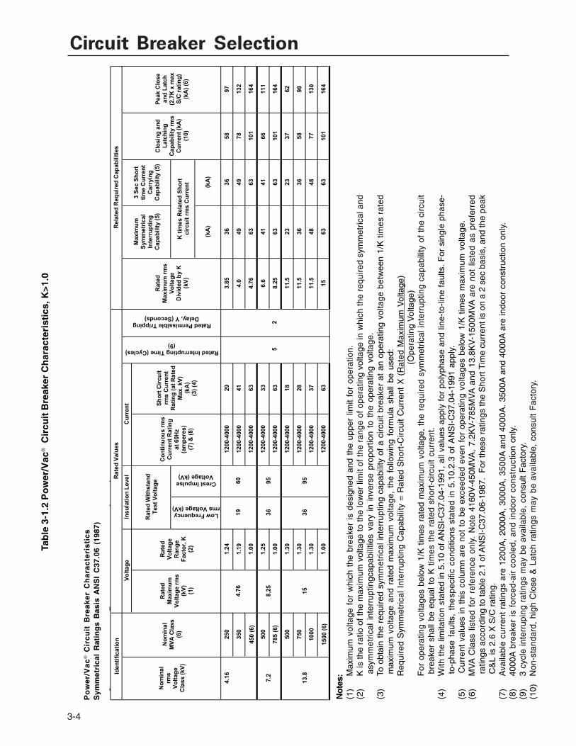
Circuit Breaker Selection
3-4
Tab
le 3
-1.2
Po
wer
/Vac
® C
ircu
it B
reak
er C
har
acte
rist
ics,
K>1
.0
PO
WE
R/V
AC
Po
wer
Cir
cu
it B
reaker
Ch
ara
cte
risti
cs
Sym
metr
ical R
ati
ng
s B
asis
AN
SI C
37.0
6 (
1987)
(kA
)(k
A)
4.1
6250
1.2
41200-4
000
29
3.8
536
36
58
97
350
1.1
91200-4
000
41
4.0
49
49
78
132
450 (
6)
1.0
01200-4
000
63
4.7
663
63
101
164
500
1.2
51200-4
000
33
6.6
41
41
66
111
785 (
6)
1.0
01200-4
000
63
8.2
563
63
101
164
500
1.3
01200-4
000
18
11.5
23
23
37
62
750
1.3
01200-4
000
28
11.5
36
36
58
98
1000
1.3
01200-4
000
37
11.5
48
48
77
130
1500 (
6)
1.0
01200-4
000
63
15
63
63
101
164
Note
s:
(1)
Maxim
um
voltage for
whic
h the b
reaker
is d
esig
ned a
nd the u
pper
limit for
opera
tion.
(2)
K is the r
atio o
f th
e m
axim
um
voltage to the low
er
limit o
f th
e r
ange o
f opera
ting v
oltage in w
hic
h the r
equired s
ym
metr
ical and a
sym
metr
ical in
terr
upting
capabili
ties v
ary
in invers
e p
roport
ion to the o
pera
ting v
oltage.
(3)
To o
bta
in the r
equired s
ym
metr
ical in
terr
upting c
apabili
ty o
f a c
ircuit b
reaker
at an o
pera
ting v
oltage b
etw
een 1
/K tim
es r
ate
d m
axim
um
voltage a
nd r
ate
d m
axim
um
voltage,
the follo
win
g form
ula
shall
be u
sed: R
equired S
ym
metr
ical In
terr
upting C
apabili
ty =
R
ate
d S
hort
-Circuit C
urr
ent X
(R
ate
d M
axim
um
Vo
lta
ge
)
(Opera
ting V
oltage)
For
opera
ting v
oltages b
elo
w 1
/K tim
es r
ate
d m
axim
um
voltage, th
e r
equired s
ym
metr
ical in
terr
upting c
apabili
ty o
f th
e c
ircuit b
reaker
shall
be e
qual to
K tim
es the r
ate
d s
hort
-circuit c
urr
ent.
(4)
With the lim
itation s
tate
d in 5
.10 o
f A
NS
I-C
37.0
4-1
991, all
valu
es a
pply
for
poly
phase a
nd lin
e-t
o-lin
e faults. F
or
sin
gle
phase-t
o-p
hase faults, th
e s
pecific
conditio
ns
sta
ted in 5
.10.2
.3 o
f A
NS
I-C
37.0
4-1
991 a
pply
.
(5)
Curr
ent valu
es in this
colu
mn a
re n
ot to
be e
xceeded e
ven for
opera
ting v
oltages b
elo
w 1
/K tim
es m
axim
um
voltage.
(6)
MV
A C
lass lis
ted for
refe
rence o
nly
. N
ote
4160V
-450M
VA
, 7.2
KV
-785M
VA
and 1
3.8
KV
-1500M
VA
are
not lis
ted a
s p
refe
rred r
atings a
ccord
ing to table
2.1
of A
NS
I-C
37.0
6-1
987.
For
these r
atings the S
hort
Tim
e c
urr
ent is
on a
2 s
ec b
asis
, and the p
eak C
&L is 2
.6 X
S/C
rating.
(7)
Availa
ble
curr
ent ra
tings a
re 1
200A
, 2000A
, 3000A
, 3500A
and 4
000A
. 3
500A
is indoor
constr
uction o
nly
.
(8)
4000A
bre
aker
is forc
ed-a
ir c
oole
d, and indoor
constr
uction o
nly
.
(9)
3 c
ycle
inte
rrupin
g r
atings m
ay b
e a
vaila
ble
, consult F
acto
ry.
(10)
Non-s
tandard
, hig
h C
lose &
Latc
h r
atings m
ay b
e a
vaila
ble
, consult F
acto
ry.
4.7
6
8.2
5
15
K t
imes R
ela
ted
Sh
ort
cir
cu
it r
ms C
urr
en
t
Rated Interrupting Time (Cycles) (9)
Insu
lati
on
Level
Rela
ted
Req
uir
ed
Cap
ab
ilit
ies
Clo
sin
g a
nd
L
atc
hin
g
Cap
ab
ilit
y r
ms
Cu
rren
t (k
A)
(10)
Peak C
lose
an
d L
atc
h
(2.7
K x
max
S/C
rati
ng
)(k
A)
(6)
Rate
d
Maxim
um
rm
s
Vo
ltag
e
Div
ided
by K
(k
V)
Rated Permissible Tripping Delay, Y (Seconds)
36
36
19
95
95
Sh
ort
Cir
cu
it
rms C
urr
en
t R
ati
ng
(at
Rate
d
Max. kV
) (k
A)
(3)
(4)
Co
nti
nu
ou
s r
ms
Cu
rren
t R
ati
ng
at
60H
z
(am
pere
s)
(7)
& (
8)
Rate
d W
ith
sta
nd
T
est
Vo
ltag
e
Iden
tifi
cati
on
R
ate
d V
alu
es
No
min
al
rms
Vo
ltag
e
Cla
ss (
kV
)
No
min
al
MV
A C
lass
(6)
Rate
d
Maxim
um
V
olt
ag
e r
ms
(kV
) (1
)
Rate
d
Vo
ltag
e
Ran
ge
Facto
r, K
(2)
Vo
ltag
e
13.8
7.2
Maxim
um
S
ym
metr
ical
Inte
rru
pti
ng
C
ap
ab
ilit
y (
5)
3 S
ec S
ho
rt
tim
e C
urr
en
t C
arr
yin
g
Cap
ab
ilit
y (
5)
Low Frequency rms Voltage (kV)
Crest Impulse Voltage (kV)
52
60
Cu
rren
t
Not
es:
(1)
Max
imum
vol
tage
for
whi
ch t
he b
reak
er i
s de
sign
ed a
nd t
he u
pper
lim
it fo
r op
erat
ion.
(2)
K is
the
ratio
of t
he m
axim
um v
olta
ge to
the
low
er li
mit
of th
e ra
nge
of o
pera
ting
volta
ge in
whi
ch th
e re
quire
d sy
mm
etric
al a
ndas
ymm
etric
al i
nter
rupt
ingc
apab
ilitie
s va
ry i
n in
vers
e pr
opor
tion
to t
he o
pera
ting
volta
ge.
(3)
To o
btai
n th
e re
quire
d sy
mm
etric
al in
terr
uptin
g ca
pabi
lity
of a
circ
uit
brea
ker
at a
n op
erat
ing
volta
ge b
etw
een
1/K
tim
es r
ated
max
imum
vol
tage
and
rat
ed m
axim
um v
olta
ge,
the
follo
win
g fo
rmul
a sh
all
be u
sed:
Req
uire
d S
ymm
etric
al I
nter
rupt
ing
Cap
abili
ty =
Rat
ed S
hort
-Circ
uit
Cur
rent
X (
Rat
ed M
axim
um V
olta
ge)
(Ope
ratin
g V
olta
ge)
For
ope
ratin
g vo
ltage
s be
low
1/K
tim
es r
ated
max
imum
vol
tage
, th
e re
quire
d sy
mm
etric
al in
terr
uptin
g ca
pabi
lity
of t
he c
ircui
tbr
eake
r sh
all
be e
qual
to
K t
imes
the
rat
ed s
hort
-circ
uit
curr
ent.
(4)
With
the
lim
itatio
n st
ated
in 5
.10
of A
NS
I-C
37.0
4-19
91,
all v
alue
s ap
ply
for
poly
phas
e an
d lin
e-to
-line
fau
lts.
For
sin
gle
phas
e-to
-pha
se f
aults
, th
esp
ecifi
c co
nditi
ons
stat
ed i
n 5.
10.2
.3 o
f A
NS
I-C
37.0
4-19
91 a
pply
.(5
)C
urre
nt v
alue
s in
thi
s co
lum
n ar
e no
t to
be
exce
eded
eve
n fo
r op
erat
ing
volta
ges
belo
w 1
/K t
imes
max
imum
vol
tage
.(6
)M
VA
Cla
ss l
iste
d fo
r re
fere
nce
only
. N
ote
4160
V-4
50M
VA
, 7.
2KV
-785
MV
A a
nd 1
3.8K
V-1
500M
VA
are
not
lis
ted
as p
refe
rred
ratin
gs a
ccor
ding
to ta
ble
2.1
of A
NS
I-C
37.0
6-19
87.
For
thes
e ra
tings
the
Sho
rt T
ime
curr
ent i
s on
a 2
sec
bas
is, a
nd th
e pe
akC
&L
is 2
.6 X
S/C
rat
ing.
(7)
Ava
ilabl
e cu
rren
t ra
tings
are
120
0A,
2000
A,
3000
A,
3500
A a
nd 4
000A
. 35
00A
and
400
0A a
re in
door
con
stru
ctio
n on
ly.
(8)
4000
A b
reak
er i
s fo
rced
-air
cool
ed,
and
indo
or c
onst
ruct
ion
only
.(9
)3
cycl
e in
terr
upin
g ra
tings
may
be
avai
labl
e, c
onsu
lt F
acto
ry.
(10)
Non
-sta
ndar
d, h
igh
Clo
se &
Lat
ch r
atin
gs m
ay b
e av
aila
ble,
con
sult
Fac
tory
.
Po
we
r/V
ac
® C
irc
uit
Bre
ak
er
Ch
ara
cte
ris
tic
sS
ymm
etri
cal
Rat
ing
s B
asis
AN
SI
C37
.06
(198
7)

Section 3
SYSTEM FREQUENCY
The frequency rating of Power/Vac metalclad switchgear should coincide with the nominal frequency of the power system. Standard Power/Vac is rated at 60-Hz (Tables 3-1.1 and 3-1.2) per ANSI standards, however can typically be applied at 50-Hz as well.
SHORT-CIRCUIT CURRENT
Quick interruption of short-circuit current is usually considered the primary function of a circuit breaker. The fault-current interrupting capability of Power/Vac circuit breakers is stated in three-phase, symmetrical, rms AC amperes. Accordingly, calculation of the maximum available fault duty of a circuit breaker assumes a three-phase bolted fault.
After calculation of short-circuit current duty, choose a Power/Vac breaker of the proper voltage class and which has a short-circuit current capability that equals or exceeds the expected duty. If applying breakers with K factors > 1.0, remember to consider the circuit operating voltage when evaluating the circuit breaker’s interrupting capability. For example: a 4.16 kV- 350 MVA-class circuit breaker has a rated short-circuit current of 41 kA at a maximum rated voltage of 4.76 kV, but has a short-circuit capability of 47 kA symmetrical rms current at 4.16 kV. However when applied on a 2.4 kV system, the interrupting capability increases to 49 kA, which is the maximum symmetrical interrupting capability listed in the rating tables, because 2.4 kV is less than 4.76 kV divided by “k”, or 4.76/1.19 = 4.0 kV.(See footnote No. 5, Table 3-1.2).
CLOSING AND LATCHING CURRENT
Circuit breakers are designed to stay latched, or to close and latch, against a first-cycle maximum asymmetrical rms current which is approximately 1 1/2 times the maximum symmetrical rms interrupting capability of the circuit breaker. This close and latch capability is satisfactory for most applications (Table 3-1.1 and 3-1.2). However there are some applications in which the calculated rms value of first-cycle asymmetrical short-circuit current, exceeds the closing and latching capability of the otherwise suitable circuit breaker. Applications which include large motor loads may generate these higher first-cycle currents. In these cases, breaker selection may depend on closing and latching capability
3-5
rather than symmetrical short-circuit capability. The breaker selected may have the next higher short-circuit current capability.
For circuit breakers with K factor =1.0, the closing and latching capability (kA, rms) of the circuit breaker is equal to 1.55 K times rated short-circuit current. If close & latch is expressed in peak amperes, the value is equal to 2.6 K times rated short-circuit current.
For circuit breakers with K > 1.0, closing and latching capability (kA, rms) of the circuit breaker is equal to 1.6 K times rated short-circuit current and if expressed in peak amperes, the value is equal to 2.7 K times rated short-circuit current (see ANSI C37.06-2009 for details)
CONTINUOUS CURRENT
Feeder and main breaker loading determines the required continuous current duty. For continuous loads, select a Power/Vac breaker with rated continuous current (defined at 60-Hz) equal to or greater than load current.
Note that Power/Vac circuit breakers are 100% rated, and have no continuous overload rating. When considering circuit breaker applications with a generator, a motor, a transformer, or other apparatus having a long-time overload rating, the circuit breaker (and switchgear equipment) must have a continuous-current rating at least equal to the overload rating of the served apparatus. When applied with a forced-air cooled transformer, the switchgear continuous-current rating must equal or exceed the transformer forced-air cooled current rating.
Circuit breakers may be operated for short periods, in excess of their rated continuous current. This covers such operations as starting motors or energizing cold loads. Consult ANSI C37.20.2 for overload current capability guidelines.
RATED INTERRUPTING TIME
Power/Vac circuit breakers are available with interrupting ratings of 5-cycles or 3-cycles, as stated in Tables 3-1.1 and 3-1.2.

Circuit Breaker Selection
3-6
DUTY CYCLE
Power/Vac circuit breakers have a rated dutycycle of: O – 0 sec – CO – 15 sec – CO. Power/Vac vacuum breakers do not require derating forreclosing duties.
SPECIAL SWITCHING APPLICATIONS
Application of power circuit breakers forswitching duty may require derating of the circuitbreaker, or increased maintenance. Power/Vaccircuit breakers do not require derating whenapplied in automatic reclosing duty.
Particular attention should be given to breakersintended for use in any of the following switchingapplications:
• Repetitive switching (except arc furnace)• Arc furnace switching• Reactor switching• Capacitor switching• Fast bus transfer
For these applications, the usual practice isto first select a circuit breaker based on the criteriaprovided under “SELECTION CONSIDERATIONS”of this section. Then consider the switching dutyand, if necessary, redetermine the circuit breakercapabilities (continuous-current rating, interruptingrating, etc.), and factor in any modified operatingor maintenance requirements. Recheck the circuitbreaker’s evaluation capabilities against all thebasic duty requirements under “SELECTIONCONSIDERATIONS.”
If the circuit breaker selected initially, and asderated (or otherwise modified), no longer meetsthe duty requirements of the application, choosethe next-higher rated breaker. Repeat the deratingor rating adjustment process to confirm that thenew breaker has adequate capability.
REPETITIVE SWITCHING(EXCEPT ARC FURNACE)
Power/Vac circuit breakers can be applied onmost power circuits without concern to frequencyof operation, since highly repetitive switching dutyis uncommon. Typical switching duties includemotor starting, switching of distribution circuits,transformer magnetizing current, and othermiscellaneous load-current switching. While themagnitude of current switched in these
applications can vary from very light load to the maximum permissible for a particular circuit breaker, switching is generally infrequent; thus, no derating is required.
Standard Power/Vac circuit breakers may be operated (open-close) as often as 20 times in 10 minutes, or 30 times in one hour without adverse effect. Further frequency of operation capabilities are given in Table 3-2. When operated under usual service conditions and for other than arc furnace switching, standard Power/Vac circuit breakers are capable of operating the number of times shown in the table. Operating conditions, servicing requirements and permissible effects on the breakers are specified in Table 3-2.
ARC FURNACE SWITCHING
Arc furnace switching duty is more repetitive than normal switching duty. The circuit breaker is applied on the primary side of a relatively high-impedance transformer and the usual application requires frequent switching (50 to 100 times per day) of the transformer magnetizing current. Switching is required when the transformer is de-energized for tap changing, when taking melt samples, or when adding alloys. In addition to this switching duty, transformer through-faults must occasionally be interrupted
This heavy-duty application requires circuit breaker capabilities and maintenance schedules different from those required for other switching duty.
Power/Vac circuit breakers designed for arc furnace switching are capable of operating the number of times given in Table 3-3, providing they are operated under usual service conditions. Operating conditions, servicing requirements, and permissible effects on the breakers are given in the table.
REACTOR SWITCHING
Standard Power/Vac circuit breakers are capable of switching reactive load current up the full continuous current rating of the breaker.

Section 3
�
BREAKER NUMBER OF OPERATIONS
TYPE CONTINUOUS RATING (AMPERES)
ARE FURNACE FULL-LOAD RATING
(AMPERES)
MAXIMUM NUMBER OF OPERATIONS BETWEEN
SERVICING
NO-LOAD MECHANICAL SWITCHING AND INTERRUPTING
COLUMN 1
COLUMN 2 COLUMN 3 COLUMN 4 COLUMN 5 COLUMN 6
A. Servicing consists of adjusting, cleaning, lubrication, tightening, changing parts, as recommended by the Company. The operations listed are on the basis of service in a mild environment.
H. If the weighted average of the currents interrupted during load and secondary furnace cave-ins is equal to the breaker continuous current, this column applies.
I. After 15 full short circuit faults check the contact erosion.
B. When closing and opening no-load.
C. Within 90 to 100% of rated control voltage.
D. Frequency of operation not more than 20 in 10 minutes or not more than 30 in 1 hour.
E. Servicing at no greater interval than shown in Column 4.
F. No parts replacement.
G. Breaker meets all current, voltage, interrupting currentratings.
C. Applies
D. Applies
E. Applies
F. Applies
G. Applies
I. Applies
J. At the first servicing interval, the amount of vacuum interrupter contact erosion should be used to estimate the additional life at that continued duty.
18-40kA All All 10,000 or 10 years 10,000 minimum
50 & 63kA
All All 5,000 or 10 years 5,000 minimum
Table 3-2 Repetitive Duty and Normal Maintenance for Power/Vac®
Breakers used in Mild Environments other than for Arc Furnace Switching
3-7
�
BREAKER MAXIMUM NO. OF NUMBER OF OPERATIONS (EACH = 1 CLOSE PLUS 1 OPEN OPERATION)
KA Rating CONTINUOUS RATING
- AMPS
OPERATIONS BEFORE SERVICING
NO-LOAD MECHANICAL CONTINUOUS CURRENT SWITCHING
INRUSH-CURRENT SWITCHING
COLUMN 1 COLUMN 2 COLUMN 3 COLUMN 4 COLUMN 5
A. Servicing consists ofadjusting, cleaning, lubrication, changing parts, as recommended by the Company. The operations listed are on the basis of service in a mild environment.
B. Close and trip, no-load.
E. Rated control voltage.
F. Frequency of operation not more than 20 in 10 minutes or not more than 30 in 1 hour.
G. Servicing at intervals given in Column 2.
H. No parts replacement.
I. Breaker meets all current, voltage, interrupting current ratings.
C. Close and trip within rated current, rated maximum voltage and 80% PF or greater.
E. Applies
F. Applies
G. Applies
H. Applies
I. Applies
J. At the first servicing interval, the amount ofvacuum interrupter contact erosion should be used to estimate the additional life at that continued duty.
K. After 15 full short circuit faults check the contact erosion.
D. Closing 600% of rated current or less at no less than 30% PF.Otherwise, same as C.
E. Applies
F. Applies
G. Applies
H. Applies
I. Applies
J. Applies
K. Applies
20-40kA All 10,000 or 10 years 10,000 minimum 10,000 10,000
50 & 63kA All 5,000 or 10 years 5,000 minimum 5,000 5,000
Table 3-3—Repetitive Duty and Maintenance Requirements forPower/Vac® Circuit Breakers Applied to Arc Furnace Switching

Circuit Breaker Selection
Breaker Rated Maximum Voltage
(kV RMS)
Breaker Rated Short Circuit
Current (kA RMS)
Breaker Continuous Current Rating (Amps)
1200 2000 - 4000
Isolated-Capacitor Bank or Back-to-Back Switching Amps
4.76 29 - 50 1200 12004.76 63 1200 1600
8.25 33 - 40 1200 12008.25 50 - 63 1200 1600
15 18 & 20 1200 120015 25 - 40 1200 120015 50 - 63 1200 1600
3-8
CAPACITOR SWITCHING
Capacitor banks are generally applied on bothutility and industrial power systems to improvevoltage regulation and system stability. Power/Vac circuit breakers properly equipped areapplicable as General Purpose circuit breakersfor shunt-capacitor-bank switching, or as DefinitePurpose Circuit Breakers with back-to-backcapacitor switching capabilities as listed in Table3-4.
Table 3-4 Power/Vac® Breaker Capacitor Switching Capabilities
Shunt-bank capacitor switching means onebreaker feeding one 3-phase capacitor bank. Ifthis circuit is closely paralleled by another switchedcapacitor bank, the duty is considered back-to-back. These situations require evaluation of suchfactors as local high-frequency equalizing currentsflowing between the separated, switched capacitorbanks.
Footnote — The capacitor bank rating is subject to the following conditions:
1. The transient voltage from line-to-ground, shall not exceed 3 times the maximum design line-to-groundcrest voltage measured at the breaker terminals.
2. The number of re-strikes or re-ignitions shall not be limited as long as the transient voltage to grounddoes not exceed the value given in footnote 1.
3. Interrupting time shall be in accordance with the rated interrupting time of the circuit breaker.4. Maximum Capacitor Bank KVAR rating is calculated as follows:
System Voltage (kV) x Cap. Switching Current (A) x
1.25 (for ungrounded banks) or 1.35 (for grounded banks)
5. For Back-to-Back switching, the bank inrush currents are limited to 15KA at 2000hz.6. For capacitor switching requirements other than shown above, consult Powell
Electrical.
3

Section 3
3-9
FAST BUS TRANSFER
Fast bus transfer (FBT) is an option used when there is a need for transferring from a normal power source bus to an emergency or alternate power source upon failure of the normal source of power or vice-versa, as quickly as possible without paralleling, typically within a maximum of 3 cycles (50 milliseconds). It is utilized when serving essential loads such as motors and pump applications.
During this transfer, it is essential that bus “dead time” be as short as possible to prevent loss of downstream critical auxiliary functions, such as contactors and relays. It is important that the main and alternate breakers are not closed at the same time since the sources may not be synchronous or even if they are, some short circuit conditions may result in the loss of both sources, if they are both closed at the same time. Also, when both are closed at the same time, system short circuit currents can exceed the feeder breaker rating.

Circuit Breaker Selection
3-10
In order to provide the utmost assurance that onebreaker will be open before the other is closed,accepted practice requires that the first breaker’sprimary contacts have started to open before thesecond breaker is given a closing signal. “Fast”transfer means there is no intentional time delayin the transfer of a bus or load from one source ofpower to another.
Representative timing sequences usingML-18/18H breaker mechanisms for both standardand fast bus transfer equipped breakers are shownin Figures 3-1 and 3-2.
The amount of dead bus time depends uponwhether the Power/Vac breaker is standard, or isequipped for FBT capability (provided with an early“b” (faster) contact and/or special closing coil). Abreaker “b” contact is open when the breakerprimary contacts are closed.
Fast bus transfer using Power/Vac circuitbreakers with the ML-18 or 18H mechanisms donot utilize an early “b” contact. The standard “b”contact is already sufficiently fast - approximately10 milliseconds from main contact part to “b”contact close. They are equipped with a specialclose coil, which reduces closing time to as littleas 40 milliseconds.
Power/Vac circuit breakers with an ML-17 or17H mechanism, a special early “b” contact isprovided. This “b” contact closes 3 millisecondsafter the vacuum interrupter main contacts openon the opening breaker, which initiates a closingof the second breaker. The other breaker (tie orincoming breaker) must have a special close coilthat closes the main interrupter contact inapproximately 50 milliseconds.
Typical dead times for fast bus transfer, usingstandard and special Power/Vac breakers for theML-18 mechanism are shown in Table 3-5. Fastbus transfer is only offered for 1200, 2000 and3000 ampere breakers having 125 VDC or 250VDC control voltages.
Fast bus transfer breakers must be specified whenplacing an order. Fast Bus Transfer does notrequire the use of circuit breakers rated for 3-cycle interrupting, as interruption speed doesnot impact the amount of dead bus time.
Table 3-5—Typical Dead-Times for Fast TransferUsing Power/Vac Circuit Breakers
Footnotes:(1) Control voltage at rated value.(2) Main contact parting to main contact making.(3) End of arcing to main contact making.
Dead bus times noted include allowable + operational tolerances.
Nominal Dead Bus Times (Milliseconds)Trip then close using:
Power/VacBreakers
Mechanism ControlVoltage
(volts) (1)
Early “b” contact &Special closing coil
Standard “b” contactSpecial closing coil
Standard “b” contactStandard closing coil
No Arcing(2)
No Arcing(2)
No Arcing(2)
With Arcing(3)
With Arcing(3)
All Rating ML-17 125/250 DC 62 50 90 78
With Arcing(3)
N/A N/A

Circuit Breaker Selection
3-12
SERVICE CONDITIONS
Power/Vac metalclad switchgear ratings andcapabilities are based on operation under certainspecific service conditions, defined by ANSI as“usual.” Conditions other than usual are considered“unusual” or “harsh”. Factors used to classifyservice conditions are altitude, ambienttemperature, and a variety of others, such as thepresence of atmospheric contaminants, unusualstorage conditions, and requirements for tamper-resistance. These factors are specified for circuitbreakers in ANSI-C37.04-1999 (Circuit BreakerRating Structure) and for equipment in ANSI-C37.20.2 -1999 (Metalclad Switchgear), and aresummarized here for application guidance.
Application of Power/Vac circuit breakersunder conditions other than “usual” may requiresignificant derating, special construction or use ofspecial protective features.
USUAL SERVICE CONDITIONS
Power/Vac circuit breakers (and switchgearassemblies) are suitable for operation at theirstandard nameplate ratings:
• Where ambient temperature is not above40°C or below -30°C (104° F and -22° F)
• Where the altitude is not above 1000 meters(3300 feet).
NOTE: For switchgear assemblies (breakers andhousings combined) there is one additionalstipulation:
• Where the effect of solar radiation is notsignificant. (See Ref. 5 on page 3-14.)Where radiation is significant the user isresponsible for specifying the cooling/ventilation required to limit the temperaturerise.
UNUSUAL SERVICE CONDITIONS
Abnormal Temperature
The planned use of Power/Vac circuit breakers and switchgear outside the normal ambient temperature range (-30°C to +40°C) shall be considered special. Reference should be made to ANSI C37-20.2, Table 10. Example: if installed in a 50°C ambient temperature, the switchgear continuous current ratings must be derated by 8%, per ANSI Table 10. Such applications of increased temperature should be referred to Powell Electrical for evaluation.
Temperature Rise
Per the ANSIC37.20.2 standard, the temperature rise of buses and bolted connections under rated full load current in an enclosed switchgear assembly, above the ambient air temperature outside the enclosure, must not exceed 65°C, and the total hot spot temperature must not exceed 105°C. Connections to insulated cables must not exceed a 45°C temperature rise, and a 85°C hot spot temperature when operated at rated continuous current in rms amperes at rated frequency.
The maximum rated ambient temperature is 40°C. The temperature of the air surrounding all devices in an enclosed switchgear assembly, considered in conjunction with their standard rating and loading as used, will not cause these devices to exceed their maximum allowable temperature when the switchgear assembly is surrounded by air at the maximum average ambient temperature of 40°C.
The average temperature of the air surrounding primary insulated cables in any compartment of an enclosed switchgear assembly will not exceed 65°C when the assembly is equipped with the maximum rated current devices for which it is designed.

Section 3
High Altitude
Medium voltage metal-clad switchgear isdesigned and tested in conformance to ANSIStandards. Inherent is these standards is the useof air as a heat transfer and dielectric medium. Inthe application of metalclad switchgear at highaltitudes, there are two characteristics whichdegrade above 1000 meters (3300ft). They are thecontinuous current rating and the dielectricwithstand capability, which may result in excessivecorona at operating voltages and an inability tooperate due to the dielectric breakdown of the airinsulation due to the reduced air density.
Power/Vac circuit breakers and switchgearassemblies utilize air for an insulating and coolingmedium. Operation at altitudes above 1000 meters(3300 ft) will result in a higher temperature rise andlower dielectric withstand capability because theair is thinner at the higher altitudes. Forapplications at higher altitudes, the rated 1 minutepower-frequency withstand voltage, the impulsewithstand voltage, and continuous current rating ofthe switchgear should be multiplied by thecorrection factors listed in Table 3-6 to obtain themodified or derated ratings.
When the Voltage Correction Factor isapplied to the maximum designed voltage rating of15 kV, 8.25kV or 4.76 kV for metal-clad switchgear,the derating may not permit the equipment to beinstalled at altitudes above 1000 meters, at theirrespective typical nominal system voltages.
Since it is more realistic to apply these correctionfactors to the BIL rating (impulse withstand voltage)of the switchgear, an industry accepted option is
to apply the equipment at their rated nominalvoltages, with no change in clearances, by theaddition of lighting arresters to protect theequipment.
The recommended practice is to apply theVoltage Correction Factor to the rated BIL level ofthe equipment, and provide surge protection onthe load side of the switchgear using station typelightning arresters (Tranquell® arresters), selectedsuch that the maximum discharge voltage of thearrester is about 20% less than the modifiedimpulse voltage rating of the switchgear. (SeeANSI C37.010-1999, 4.2.2)
The Current Correction Factor is applied tothe continuous current rating of the equipment only.It is necessary to derate the continuous currentrating, because switchgear assemblies depend onthe air for cooling and will have a higher temperaturerise when operated at altitudes above 1000 meters.The short-time and interrupting current ratings onvacuum breakers are not affected by altitude.Since the Current Correction Factor is small andthe actual continuous current duty is usually lessthan the equipment rating, current correction istypically not as serious a consideration as thevoltage correction. An additional consideration isthat often at higher altitude, the ambient is reduced,which can offset the higher altitude continuouscurrent derating effect.
NOTE: The recommendations are subject tomodification depending on the actual systemconditions.
3-13

Circuit Breaker Selection
Table 3-6Altitude Correction Factors for Power/Vac Circuit Breakers and Switchgear
Rated Continuous Current
Rating Correction Factors*
1.000.9950.9910.9870.9850.9700.9650.9600.9500.9400.935
3300ft - 1000m4000ft - 1200m5000ft - 1500m6000ft - 1500m7000ft - 2100m8000ft - 1500m9000ft - 1500m10000ft - 3000m12000ft - 3600m13000ft - 4000m14000ft - 4300m
Rated Voltage
1.000.980.950.920.890.860.830.800.750.720.70
Altitude(feet / meters)
Application of metal-clad switchgear above 1000 meters (3300 ft) should be referred to Powell Electrical. It should be cautioned that the correction factors of power transformers are different than those for switchgear.
Besides abnormal temperature and high altitude there are other unusual service conditions, which may require special protecting features or affect construction. Some of these are:• Exposure to corrosive atmosphere, explosive fumes, excessive dust (e.g., coal dust, paper fibers)
or particulate contamination, salt spray, steam, dripping water, and other similar conditions.
• Exposure to abnormal vibration, shock, unusual transportation, or special storage conditions.
• Installations accessible to the general public.
• Special duty/operating requirements of equipment.
BREAKER MOUNTED ACCESSORIES
Each Power/Vac breaker has two “a” and three“b” breaker auxiliary contacts wired from thebreaker-mounted auxiliary switch for thePurchaser’s use. Additional breaker contacts fromoptional compartment mounted switches areavailable, see Section 7.
A redundant tripping circuit on Power/Vaccircuit breakers can also be furnished via anoptional second or “dual” trip coil. This option was
3-14
designed specifically for use on utility breakersand on breakers applied in power-stationswitchgear applications. This feature is seldomused in industrial or commercial applications sincethe standard Power/Vac trip circuit is extremelyreliable.
Power/Vac circuit breakers can be providedwith an optional direct-acting undervoltage tripdevice. The undervoltage trip device is a factory
* From ANSI C37.20.2 - 1999, Table 8.

Section 3
Figure 3-3
3-15
installed unit, which is an integral part of the breaker mechanism. Its function is to monitor the trip circuit control voltage and to mechanically trip the breaker if that control power drops below a preset value. (See page 4-5.)
Note that the options for a dual trip coil and the undervoltage trip device are mutually exclusive. Both cannot be utilized on the same breaker.
Standard Power/Vac design uses a lift truck, for lifting and inserting/removing the circuit breakers from the breaker cells. For designs using only 1-high breaker arrangements, with the breakers located in the bottom compartments, Powell Electrical offers an option for roll-in breakers. Roll-in breakers have a wheeled undercarriage bolted to the bottom of the breaker frame, which raises the breaker to the proper height to interface with the breaker cell connections. The breaker cell floor frame is modified to allow the breaker to roll directly from the finished floor into the cell, without the need for the lift truck described in the following section. Note roll-in breakers cannot be inserted into a “standard” breaker cell without removing the bolt-on undercarriage, and using the lift truck.
BREAKER LIFT TRUCKS
Powell Electrical offers two basic styles of lift trucks for handling Power/Vac circuit breakers, ground and test devices, roll-out transformer trays and fuse roll-outs. The first is a double masted truck that is available with two swivel casters in the rear and two straight wheels in the front. This truck is compatible with indoor switchgear and provided as a standard with every order. However, to reach the top rollout drawer in an upper compartment, a different single masted truck is required. The dimensions of the double masted truck carriage are width of 47 inches and a total width of 50 inches with the winch handle installed. The depth with arms extended is 46 inches, and the standing height is 86 inches. This style of truck cannot be used with outdoor aisle-less switchgear. See Figure 3-3.
The second style is a single-masted truck thatis available with all swivel casters. As shown inFigure 3-4. This truck is compatible with outdoorswitchgear and is required to reach the uppercompartment rollout on indoor equipment. Themaximum handle load is 15 lb. with a 850 lb. load.The typical dimensions of the single masted truckare width 36.5 inches, depth is 47 inches (witharms extended 55.5 inches), and the standingheight is 79.5 inches extendible to 137.5 inches.The legs at the base of the lift truck are adjustablein width from 31.5 inches to 58 inches. This allowsthe legs to be narrowed to the width of the breakerfor moving through doorways. Caution; whilelowering the breaker from the cubicle to thefloor the width of the legs must maintain aminimum width of 44 inches.
The single-mast lift truck can be collapsed forstorage. The width is 39 inches with arms andlegs collapsed, the depth is 29 inches and theheight is 77 inches.

Circuit Breaker Selection
Both style of lift trucks are provided with interlocksto retain the device being handled and to lock thelift truck to the switchgear while a device is beinginserted or removed. The carriage, which lifts adevice, is raised or lowered by means of a winchand cable. When the winch handle is releasedthe carriage is held in that position by means of aclutch-brake internal to the winch. Two arms areattached to the carriage for engaging the trackrollers on the sides of each device.
The lift trucks are functional for both theupper and lower compartments of Power/Vacprovided the equipment is mounted on nomore than a 4 inch housekeeping pad. Padcannot extend beyond the front frame of theequipment more than 3 inches.
1. ANSI Standard C37.06-2009, Schedules of Preferred Ratings and Related Required Capabilities for AC High Voltage Circuit Breakers Rated on a Symmetrical CurrentBasis.
2. ANSI Standard C37.010-1999, Application Guide for AC High Voltage Circuit Breakers.
3. ANSI Standard C37.04-1999, Circuit Breaker Rating Structure.
4. ANSI Standard C37.20.2-1999, Metalclad Switchgear Assemblies.
5. ANSI Standard C37.24-1986, Guide for Evaluating the Effect of Solar Radiation on Outdoor Metalclad Switchgear.
6. ANSI Standard C37.100-1992 Definitions for Power Switchgear.
3-16
Figure 3-4
Recommended minimum working access requirements for the lift trucks of indoor switchgear is a 78 inch front aisle space with an 18 inch right side and a 12 inch left side clearance. Outdoor switchgear requires a 66 inch front aisle space with a 36 inch left side and a 18 inch right side clearance required as standard minimum space. Smaller front aisles may be used if the required right side space is available but the factory must be consulted for an engineering evaluation.
REFERENCES

Section 4
4-1
Section 4Control Power Equipment
PageINTRODUCTION ................................................................................................ 4-2
CONTROL POWER REQUIREMENTS .............................................................. 4-2 Closing And Tripping ..................................................................................... 4-2
Breaker Tripping ........................................................................................ 4-4 Breaker Closing ......................................................................................... 4-5
Indicating Lamps ........................................................................................... 4-6 Equipment Heaters ........................................................................................ 4-6 Comfort Heating ............................................................................................ 4-6
Relaying ........................................................................................................ 4-6 Fans .............................................................................................................. 4-7 Lights ............................................................................................................ 4-7 Convenience Outlets ...................................................................................... 4-7 Excitation Power............................................................................................ 4-8 Breaker Remote Racking .............................................................................. 4-8 Other Loads .................................................................................................. 4-8
CONTROL POWER SOURCE SELECTION ...................................................... 4-9 DC Control Power Equipment ........................................................................ 4-9 Lead-acid Batteries .................................................................................... 4-9
Nickel-cadmium Batteries ........................................................................... 4-9 Battery Capacity and Sizing ...................................................................... 4-10 Battery Chargers ....................................................................................... 4-12
AC Control Power Equipment ...................................................................... 4-13 Application ................................................................................................ 4-13 Selection .................................................................................................. 4-13
GUIDE FOR ESTIMATING THE HEAT LOSS ................................................... 4-14 In Power/Vac® Switchgear
Contents

Control Power Equipment
4-2
INTRODUCTION
This section of the Application Guideaddresses specific control power requirements andprovides guidance in selecting the proper type ofcontrol power equipment.
CONTROL POWER REQUIREMENTS
Equipment necessary to provide control powerfor Power/Vac switchgear must have sufficientcapacity to deliver the maximum power required,at the proper voltage, under any operatingcondition.
The most important consideration in selectinga control power source is that it must providetripping power for the circuit breakers duringprotective relay operation. Also, it should becapable of closing the breakers without directmanual operation. Other requirements caninclude:
All of these requirements must be consideredin determining the type and rating of the controlpower source.
Sources of control power for Power/Vacmetalclad switchgear are storage batteries (withcharger) for DC control, and transformers for ACcontrol. When AC is used for control, the trippingpower is obtained from capacitors contained withintrip devices, which are fed from rectified AC. Thechoice between these alternatives depends onfactors such as the size of the switchgearinstallation, the need to operate breakerssimultaneously, the degree of reliability required,expansion plans, the expected environmental
conditions, maintenance support availability, andthe economics related to these considerations.
CLOSING AND TRIPPING
Successful operation of Power/Vac metalcladswitchgear depends on a reliable source of controlpower which will, at all times, maintain a voltageat the terminals of electrically operated deviceswithin the rated operating voltage range. In general,the required operating range of the control powervoltage in the switchgear equipment is determinedby the rated operating voltage range of the circuitbreaker. These ranges are established by ANSIC37.06 standards. Control voltage and operatingcurrents for Power/Vac circuit breakers are givenin Table 4-1 and 4-2.
DC Indicating lamps Relay power supplies Emergency lights Emergency motors Excitation power (brushless motors, etc.)
AC Indicating lamps Relay power supplies Equipment Heaters Equipment Lights and Convenience Outlets Excitation power (brushless motors, etc.) Equipment ventilating fans Remote lights (on structures, etc.)

Section 4
4-3
Table 4-1 Control Voltage and Operating Currents forPower/Vac ML-17 & 17H Breaker Mechanisms (Type VB)
Breaker Control Closing Tripping Charge ChargeSource Voltage Voltage Motor Inrush Motor RunVoltage Range Range Standard W/FBT 5 Cycle 3 Cycle Current Current (3)
48VDC 38-56VDC 28-56VDC 9.6 N/A 26.0 26.0 29.0 12.3125VDC 100-140VDC 70-140VDC 6.0 32.0 10.2 6.0 18.3 3.7250VDC 200-280VDC 140-280VDC 3.0 12.0 5.2 5.2 9.9 2.3120VAC 104-127VAC 108-132VAC (1) 8.0 N/A 10.2 6.0 13.6 4.9240VAC 208-254VAC 216-264VAC (2) 10.3 N/A 2.3 2.3 7.2 3.0
Closing Coil Current Tripping Coil Current
1. 120VAC control voltage for tripping requires the use of a 120VAC capacitor trip device. Cap trip devicedelivers 170VDC (peak) into a 125VDC trip coil.
2. 240VAC control voltage for tripping requires the use of a 240VAC capacitor trip device. Cap trip devicedelivers340VDC (peak) into a 340VDC trip coil.
3. Approximate spring charging time for ML-17 & ML-17H mechanisms is 7 seconds.4. FBT = Fast Bus Transfer, requires special closing coil.

Control Power Equipment
4-4
Breaker Tripping
Tripping power availability should beindependent of the voltage conditions present onthe power system associated with the switchgear.
Power/Vac circuit breakers are provided withmeans for manual tripping (push button) and forelectrically actuated tripping (trip coil). Electricallyactuated tripping devices are used for twofunctions:
• As a means of opening the breaker in theprocess of normal switching operationsinitiated by an operator, or
• As a means of automatically opening thebreaker for circuit protective purposes,under abnormal conditions.
Electrical tripping is accomplished whenexternal power, from a battery or from a rectifiedAC source (with capacitor), is directed into thebreaker trip coil. Normal circuit switchingoperations use an operator control switch toenergize the trip coil. Automatic tripping occurswhen a protective relay senses an abnormalsystem condition through the power circuitinstrument transformers, and closes outputcontacts in the trip circuit.
When deciding between DC battery trip andAC capacitor trip, the following points must beconsidered:
• For a single breaker or a few breakers,AC control with capacitor trip devices mayhave lower cost than a battery system,but a separate trip device is required foreach breaker and lockout relay.
• A battery source is more reliable, butrequires more maintenance than acapacitor trip device. However capacitortrip devices also contain smallrechargeable NiCad batteries, which mustbe checked and replaced periodically.
• If a battery is used for tripping, DC closingpower can also be obtained for littleadditional cost.
• If non-self powered microprocessor relaysare utilized for protection with AC controlpower, a small UPS should be includedto ensure the relay power supplies remainpowered-up during system disturbancesor during transfers of the AC control powerfrom normal to emergency source.
DC BATTERY TRIP—When properly maintained,a battery bank offers the most reliable trippingsource. It requires no auxiliary tripping devices,and uses single-contact relays, which directlyenergize a single trip coil in the breaker. Powercircuit voltage and current conditions during timeof faults do not affect a battery-trip supply;therefore, it is considered the best source for circuitbreaker tripping. Additional advantages are thatusually, only one battery bank is required for eachlocation, and it may be used to operate otherequipment such as high-voltage circuit breakersor protective grounding switches.
Once a battery bank has been selected fortripping purposes, it can, after proper evaluation ofadditional loads, also be used for breaker closingpower. For indoor applications, if the battery bankcan be located close to the switchgear, a 48-voltbattery operating level is usually suitable. For moregeneral use, a 125-volt battery is recommended,but 250-volt batteries can be used if otherconditions require that voltage.
General space requirements when thebatteries are to be mounted in the outdoor (NEMA3R) switchgear, are one 36 inch wide Power/Vacstack for a 48VDC battery bank and two 36 inchwide Power/Vac stacks for a 125VDC bank. Inaisle type outdoor construction, 36 inch wideempty “work-spaces” are added to house thebattery system. Note on indoor (NEMA 1)applications, batteries are typically not locatedwithin the switchgear structure.
Long service can be obtained from batterieswhen they receive proper maintenance, are keptfully charged, and when the electrolyte ismaintained at the proper level. For equipment inoutlying locations where periodic batterymaintenance would be difficult, the capacitor tripdevice may offer overall advantages.

Section 4
4-5
Power/Vac AUTO-CHARGE CAPACITOR TRIP DEVICE— The Automatic Charging Capacitor Trip Device is used to trip circuit breakers and lockout relays when AC control power source is utilized. The Applicator Trip Device converts AC control bus voltage to DC voltage and stores enough energy to operate a lockout relay or trip a circuit breaker, often more than once. The Applicator Trip Device, with batteries fully charged, will maintain a charge for a minimum of 3 days after the AC power has been interrupted. In normal operation, the batteries are trickle charged from the AC voltage source.
DC voltage is available from the unit for tripping immediately upon AC voltage power up. Capacitors do not need to be charged to have tripping voltage available on the output of the device. This is because the output is automatically fed from the full wave bridge rectified AC signal, or the charged capacitors, whichever is greater. Capacitor charge current is limited to protect the control power system from a large current in-rush. This feature allows the use of many Applicator Trip Device units from the same control power voltage source without coordination problems. Additionally, the Applicator Trip Device is self-protected from short circuit damage on the output. The Automatic Charging Capacitor Trip Device is provided on PowerVAC circuit breakers whenever AC control voltage is specified. 120VAC and 240VAC control power sources are available.
DIRECT ACTING UNDERVOLTAGE TRIP DEVICE—Most Power/Vac circuit breakers can be provided with a direct acting undervoltage trip device. The undervoltage trip device is a factory-installed unit, which is an integral part of the breaker mechanism. Its function is to monitor the DC trip control voltage and to mechanically trip the breaker if that control voltage is lost. The UV device will also block closing of the breaker if the control voltage is not 80% or more of the nominal value.
NEMA Standard Publication No. SG4-1990 paragraph 3.9 requires the dropout range of undervoltage trip devices to be 30 to 60 percent of the rated voltage. The Power/Vac undervoltage device trips the breaker in the range of 15 to 60 percent of the nominal tripping control voltage.
Control Voltage48 VDC125 VDC 250 VDC
Specifications, which require tripping to occur at some voltage higher than 15 percent of normal, should be provided with a voltage sensing relay to remove trip control voltage from the undervoltage trip device to assure breaker tripping at the desired voltage.
Breaker Closing
Closing power availability should also be independent of voltage conditions on the power system associated with the switchgear as with tripping. Accordingly, a DC battery bank is normally considered to be the most reliable auxiliary power source. Nevertheless, in many instances, the battery bank or other independent power source necessary to achieve this goal may require an investment, which is considered too high for the advantages gained. This is particularly true for small switchgear installations, consisting of only a few circuit breaker units.
NOTE: When equipment is initially installed and control power is first energized, all Power/Vac breakers that are in the connected position will immediately begin to charge their closing springs, which may overload an otherwise properly sized AC or DC source. It is recommended to either rack breakers in to the connected position one at a time after control power is established, or pull all the individual breaker close circuit fuse blocks/disconnects prior to energizing the control power circuit.
Generally, the choice between DC closing power derived from a battery and AC closing power derived from a control power transformer is an economic one, dictated by desired system reliability. There are other factors, however, which also influence this choice. These are:
• Need to close breakers with the power systemde-energized.
• Availability of housing space for a battery andits associated charging equipment.
• Estimated ambient temperature extremes andthe effect on battery capability.
• Maintenance requirements for a battery andbattery charger.
• Expected future equipment additions, whichmay affect the present choice of closing-powersource.Tripping Range
7-29 VDC19-75 VDC38-150 VDC

Control Power Equipment
4-6
When the closing mechanism is operated fromAC, the current required is such that it can betaken from a control power transformer or a general-purpose or lighting source, internal or external tothe switchgear. The energy for the next operationis stored in the springs as soon as the breaker isclosed. To permit control switch or automaticinitiation of closing, the AC source must also bepresent at the time of breaker closing to energizethe spring-release solenoid (close coil). The Power/Vac breaker mechanism is also capable of manualoperation, if necessary, both for charging thesprings and for releasing them to close the breaker.
For any control power source used for breakerclosing, the maximum closing load should becalculated using Table 4-1 and 4-2 values. Usually,only one breaker will be closed at a time, but thepossibility of simultaneous closing of two or morebreakers must be examined. This possibility willdepend on the type of application and any specialcontrol requirements, such as load restoration.Simultaneous closing of two breakers could occurwith multiple-breaker, motor starting equipment,or with automatic reclosing breakers. Also, onlarge installations, with several different controlpoints, different operators could causesimultaneous manual operations.
INDICATING LAMPS
Position indicating lamps for each circuitbreaker are operated from the trip fuses with DCclosing power, or the closing fuses on either ACcontrol or a “tripping only” battery. These lampsrepresent a small, but steady load, which is ofconcern particularly in DC applications. The totalload is the sum of:
• One indicating lamp per breaker.• Lamps used to supervise fuses of lockout
relays, etc.• Additional lamps, if any, used for remote
indication in parallel with switchgearlamps.
Burden is usually 0.035 amperes per lamp, regardless of voltage, and is assumed to be carried (by the battery) for not more than eight hours.
EQUIPMENT HEATERS
On outdoor designs, moisture condensation is minimized through the use of strip heating elements. Heater elements are located in each breaker or auxiliary compartment and each cable compartment with a total of 300 watts per vertical section. Heaters are rated 300W at 240VAC, but are applied at half-voltage, which reduces heat output to 75 watts each for extended life and are protected by perforated metal guards to prevent inadvertent contact with the heater element. Heaters are supplied on indoor designs only if specified by the purchaser.
Heaters should be energized at all times to guard against condensation caused by wide ambient temperature excursions. Accordingly, heater switches or thermostats are provided in the heater circuit only upon customer request.
COMFORT HEATINGPortable Comfort heaters for use in outdoor
aisle-type Power/Vac installations, must be supplied by the Purchaser. A grounding-type receptacle, rated 250 volt AC, 20 amperes, is provided at each end of the aisle for portable comfort heater connection.
When sizing the AC control power source, allow 5000VA load at 240VAC for each heater receptacle intended for use.
RELAYING With DC control power, allowance must be
made for simultaneous tripping of two or more breakers. Requirements for simultaneous tripping depend first, on the number of breakers on the DC source, and second, on the kind of relaying. Based on probability considerations, a guide to the possible number of simultaneous tripping is given in Table 4-3.

Section 4
4-7
Table 4-3Simultaneous Breaker Tripping
Lockout relays, when present, as in differentialrelay circuits, require special treatment:
• With AC operation, a capacitor trip devicemust be included for operation of eachlockout relay.
• With DC operation, the lockout (86) relaycoil current must be added to thesimultaneous breaker demand, since therelay does not cut itself off until after thebreaker coils have been energized.
In addition, all solid-state relays unless “self-powered”, have internal AC or DC power supplieswhich must be included in the total steady-stateload. VA burden for typical solid-state protectiverelays fall between 10VA and 35VA, depending onmanufacturer and model. Consult the specificdevice manufacturer’s catalog.
FANS
On outdoor aisle-type Power/Vacswitchgear, roof fans for aisle ventilation areavailable as an option. The standard fan uses a 1/3 hp single-phase motor, for operation from 120VAConly; allow 333 VA per fan.
Substation transformers associated withswitchgear sometimes include fans. Whenenergized from the switchgear control powersource, the fan load must be included in the totalburden on the source. Usually this is a 240-volt,single-phase load; from one to several kVA pertransformer.
On indoor 4000A Power/Vac switchgear,4000A rated breakers require forced-air cooling.Each 4000A breaker utilizes two fans, eachdrawing 6A at 120VAC or 3A at 240VAC.
LIGHTSOutdoor Power/Vac switchgear, both aisle
and non-aisle types, is provided with receptaclesfor 120-volt incandescent lamps. The control powerallowance for these should be 100 Watts per verticalsection.
Other lighting loads, such as outsidefloodlights, must be factored into the AC controlpower load based on actual requirements.
CONVENIENCE OUTLETS
In outdoor Power/Vac switchgear, 115-voltduplex grounding convenience outlets are provided.
Number of Breakers in IIneup 1 2 3-5 6-10 Above 10
Breakers Tripped By:
Time delay fault protectionInstantaneous fault protectionUndervoltage or bus differential (b)
(a) Depends upon operating conditions.(b) Use of single undervoltage or bus differential relay for tripping all breakers.
1 1 2 3 (a)1 1 3 4 (a)1 1 All All All
Probable Maximum Number of BreakersTripping Simultaneously
Number of Breakers in IIneup

Control Power Equipment
4-8
With aisle-less design, one outlet is provided pervertical section. With aisle-type construction, oneoutlet is located at each end of the aisle.
Control power allowance should be anominal 500 Watts for each duplex outlet.
EXCITATION POWER
When synchronous motors with brushlessfield excitation are controlled directly from theswitchgear, power for the exciter field source issometimes required from the switchgear controlpower source.
This excitation demand varies with themachine, from 1 to perhaps 8 amperes DC, usuallyat approximately 100 volts. With rectified ACsupply to the field, the AC equivalent of the DCfield current must be included the total CPT loading.(As a first approximation, multiply the DC amperesby 1.15 and convert to VA by multiplying thisproduct by 125 volts.) When the exciter field isfed directly from the battery, the field demand, asa nominal 8-hour load, must be included in the DCsteady load total.
Generators with static regulators usuallyrequire a separate transformer on the incomingleads of the generator breaker. This transformeris of the same epoxy-cast coil, dry type, as theswitchgear CPT, but is located in its own rollouttray. Such dedicated transformers are not part ofthe regular control power loading.
BREAKER REMOTE RACKING
When the optional motor driven remote rackingdevice is utilized, the load on the control powersource is 4.5A for the120VAC model and 2.5A forthe 240VAC.
OTHER LOADS
With DC control, when the charger is suppliedfrom the switchgear AC control power transformer,the charger load must be included in the total ACdemand. Using charger DC ampere rating as abase, some ratios of equivalent AC load atdifferent supply and battery voltages are tabulatedin Table 4-4.
For example, a 6-ampere charger, fed 115VAC,and supplying a 125VDC battery bank, has an ACload of approximately 13.8 amperes (6 A x 230%)at full output, or 1590 VA (13.8 A x 115 V). Whilethis would be an intermittent condition, with thenormal load being about 0.5 to 1.0 amperes DC,the AC control source must be sized to handlethe 13.8 ampere load.
With automatic control schemes, some relayswill be energized continuously after the first breakeris closed. The amperes drawn by these relaysmust be totaled and included with the indicatinglamp load, etc., to arrive at the total steady load.
Emergency loads on switchgear batteries,such as room lights or DC pump motors, usuallyresult in a much larger battery bank than requiredfor the switchgear alone. Lights are usuallyassumed to be used for three hours, and thenextinguished. Motor load duration must bespecified by the user.
CONTROL POWER SOURCE SELECTION
For a particular station, selection of a controlpower source may require sizing of a battery, acontrol power transformer, or sometimes both. Thefirst step is to establish the size of each load ofthe various types discussed. Second, for batteries,the short-time loads, such as breaker tripping, andthe steady load, such as lamps, must be convertedto a common rate base.
Table 4-4
AC
Supply Voltage
AC Load Factorfor Charger
Battery Voltage
115 V 75% 230% 230 V 38% 115%
48V 125V

Section 4
4-9
With the relatively small demands placed on the control power source by individual breakers, as detailed in Table 4-1 and 4-2, other loads must be evaluated carefully, since they may represent the major demand. Particularly with batteries, long-time loads must have a time period stated, since a battery bank, with the charger “off”, is not a “continuous” source.
DC CONTROL POWER EQUIPMENT
Powell Electrical does not design, manufacture or test storage batteries. Powell, when required, will select and furnish batteries and their charger as specified by the customer and in accordance with the requirements of the switching devices and the over-all station operation.
A DC control power source consists of a storage battery bank, rack and an associated charger. The battery bank is connected to the DC control power bus and the charger at all times. Large momentary loads are supplied from the battery bank, but it otherwise does very little work in normal operating situations.
The basic requirements of a storage battery are it must be capable of being trickle charged so that under normal conditions the battery is always fully charged and its terminal voltage held substantially constant. The trickle charge voltage must be less than the upper voltage limits of lamps and continuously energized coils and should not fall below a specified minimum voltage during maximum normal momentary discharge. This is to insure adequate closing voltage at the breaker mechanism terminals after making allowances for voltage drop in connections between the battery bank and the breaker mechanism.
Two types of batteries are used with switchgear that have the characteristics which meet the requirements for closing and tripping functions: lead-acid or nickel-cadmium. Several classes of each type are produced, each with different costs and with different ratios between short-time and long-time capacities. The exact type and class must be established before performing the conversion of loads to a common rate base.
Lead-acid Batteries
Common lead-acid battery types:
• Pasted plate, with lead-antimony grids.
• Lead-calcium; a pasted-plate constructionwith calcium replacing antimony as theadditive for grid strength.
Pasted plate, lead antimony, is the basic lead-acid battery, familiar in another form as theautomobile battery. For control work (comparedto auto batteries), thicker plates and lower gravityof acid provide longer life and allow long-timetrickle or “float” charging. With different platethicknesses, expected life is from 6 to 14 years.
Lead-calcium construction has longerexpected life (up to 25 years) than lead-antimonyat a rather small increase in cost. The “pure lead”electrochemical characteristics, compared to theother classes, require slightly different (higher)charging voltages.
Nickel-cadmium Batteries
Nickel-cadmium batteries are more expensivethan lead-acid, in general, but have advantages.Maintenance is less, life is longer, low-temperaturedischarge currents are higher for a given size, andthey can be charged more rapidly.
Pocket-plate cells are the normal constructionused with switchgear; they are made in threedifferent plate thicknesses. The thickest platesare not suitable for short-time applications.Medium or thin-plate cells are used withswitchgear; the choice depending upon the relativeamounts, respectively, or long- or short-time load.
Sintered-plate construction, which is relativelynew, is used mostly in “cordless” appliances,seldom in switchgear.
Lead-Acid NiCad
Initial Cost Lower HigherMaintenance Higher LowerLife Expectancy Lower Higher

Control Power Equipment
4-10
Battery Capacity and Sizing
The capacity of a storage battery is usuallyexpressed in ampere-hours (one amp for one hour,or the product of amperes output multiplied byhours of discharge, with the basic rate being eighthours). Battery capacity, however, may beexpressed at many time-rates other than the eight-hour rate.
For switchgear short-time loads, such asbreaker tripping, the one minute rate per cell(discharging to 1.75 volts for lead, or 1.14 volts fornickel-cadmium) is used. The one-minute ratedoes not exhaust the battery completely; rather,it is the rate which causes the terminal voltage todrop to the stated value early in the dischargeperiod.
Further, the actual value of discharge capacityof a storage battery may vary over a wide rangewith battery temperature. Published data is forcells at 25° C (77° F), and battery rating factorsmust be reduced when the battery is at a lowertemperature. For capacity rating factors refer toIEEE worksheets.
Generally the effect of high temperatures forevery 15° F above 77° F the lead acid battery loses50% of its useful life and for the same temperaturedecrease, the nickel-cadmium loses 20% of itsuseful life. The one-minute rating at -10° C (15°F), for instance is half the 25° C rating.
In calculating the battery loads you mustconsider three types of loads: Continuous loadsare those that are energized for the duration of theduty cycle. These have a major effect of batterycapacity. Non-continuous loads are energized foronly a portion of the duty cycle. If the inception of
the load is known, but the end is not or reverse,then you must consider it as the known portion ofthe duty cycle. Last are momentary loads whichare very short in duration, they can be a fraction ofa second, but you must treat it as lasting one fullminute.
• Direct use of specification sheets, orsoftware programs, etc. from batterymakers.
• Referral of data to battery manufacturers.
• Referral of calculated data to switchgearmanufacturers.
For direct calculation, the battery is assumedto have carried its steady loads for eight hours,and then as the worst case subject to themaximum load involving the one-minute rate.
Indoor locations assume that the battery is at25° C (77° F); outdoor locations at -10° C (15° F).A minimum size limit of cell is suggested to allowfor unknowns: 20 ampere-hours for lead-acid, or15 ampere hours for nickel-cadmium.
A small station, for example, with the batterylocated indoors, might have three breakers, withclosing and tripping duty, and no steady loadexcept the switchgear indicating lamps. Two ofthe breakers have instantaneous settings on theirovercurrent relays, so that per Table 4-3simultaneous tripping of these two breakers mightoccur. Steady lamp load, thus, is 0.035 A x 3 =0.105 amperes. Maximum short-time loads, givenfor both 48-volt and 125-volt DC to illustrateprocedure, are shown in Table 4-5.
Table 4-5 Battery Sizing Information

Section 4
Example: 48 V 125 V
26 A 10.2 AControl voltage, DCML-17 Trip coil current ML-17 Spring motor current 12.3 A 3.7 A
4-11
* Conversion factors to convert to “common ratebase” (i.e., from one-minute rate to eight-hourrate) are: 1.5 for the lead-acid batteries (pastedplate); 2.9 for the nickel-cadmium batteries (thinplate or high rate). Please note that conversionfactors vary by cell size; therefore, the factorsused in this example are not applicable forbatteries of other sizes.
Analyzing these totals, the lead-acid batteryat 48 volts with a nominal ampere-hour rating of30AH will be required. As an alternate at 125 volts,the minimum 20AH lead-acid battery will besufficient. The minimum nickel-cadmium batteryof 15AH will be sufficient at 48 volts and at 125volts.
In addition, since the total ampere-hoursrequired in each case is less than the ampere-hour capacity of the selected cell, reserve capacityis available. The matter of reserve capacity islargely related to how long the charger may be off.This no-charge condition has been known to lastfor several days. Thus, a “DC low-voltage alarm”option in the charger may be desirable to warn ofsuch conditions.
For the same station, with the battery atoutdoor temperatures, the one-minute demandmust be doubled before converting to ampere-hours. The eight-hour rate needs a smallerincrease of about 30 percent. Note that theseconversion ratios generally decrease as cell sizeincreases; hence, the approximate size of cellbeing considered must be determined before theconversion factors can be determined.
In arriving at the actual size of the battery bank,care must be taken to review the calculated amp-hours or cell requirement and then take intoaccount the recommended design factor of 10%times the calculated values and then an agingfactor of 25% times the calculated values. Thecombined sum of these calculations will providethe actual size of the battery bank.
Battery Type: Lead-acid Nickel-cadmium
Control voltage (volts) 45 125 48
Maximum 1-minute demand (amperes)
34 20.4 34 30.4
8-hr. equiv. of 1-min. demand (Max. demand divided by conversion factor*) (amp-hrs)
22.7 13.6 11.7 7.03
Lamp load
(0.105A x 8 hrs.) (amp-hrs) 0.84 0.84 0.84 0.84
Total amp-hrs
(8 hr. rate) 23.54 14.44 12.54 7.87
Since two breakers can trip at once in this example, maximum current from this load is either 17A x 2, or 10.2A x 2, respectively, 34 or 20.4 amperes total at 48 or 125 volts. Comparing this with charging motor current, we see that the trip current is larger, so trip current will be used in the next step as illustrated in Table 4-6.
Table 4-6 Battery Sizing Example

Control Power Equipment
Battery Chargers
Battery chargers have been built both asunregulated or “trickle” chargers, and as voltage-regulated chargers. The latter type provides longerlife for the battery, particularly if it is a lead-acidbattery. Voltage-regulated chargers are consideredstandard for switchgear applications.
The charger must be selected with an ampererating sufficient to satisfy the simultaneousdemand of the following three functions:
• Self-discharge losses of the battery.
• Steady load of the station: indicatinglamps, relays, etc.
• Equalizing charges, or other high-rateoutput requirements.
The self-discharge or “trickle” current of a lead-acid battery starts at about 0.25 percent of theeight-hour rate, and increases with age to about1.0 percent of that rate. Nickel-cadmium cellscan be assigned a similar trickle current.
Steady load is made up of the long-time loadsmentioned earlier in this section.
Equalizing charge is a monthly requirementfor lead-acid batteries except for the lead-cadmiumclass. When the charger is first switched to thehigher equalizing voltage, the battery demandscurrent equal to about 20% of its eight-hour rate.Nickel-cadmium batteries do not requireequalizing, but it is convenient to use the samenumbers as for lead-acid in establishing thecharger capacity to be used for occasional“boosting” of the nickel-cadmium battery.
4-12
In sizing the charger, the first numberconsidered should be the steady load from thepreceding battery calculations. Add to this load,the equalizing charge current. A quick way to findequalizing amperes is to divide the battery ampere-hour capacity (at the eight-hour rate) by 40. Thesum of steady load and equalizing amperes is thencompared with a list of battery charger ratings;select a charger with a rating that equals orexceeds this sum. The trickle current, unlessknown to be quite large, is usually covered by themargin between the standard charge rating andthe sum of steady and equalizing loads.
Occasionally a battery is shipped “dry,” withelectrolyte added at its destination. Such batteriesrequire a “conditioning” charge after filling; theamperes needed for this are 25% of the eight-hourrate, but with no other load connected.
AC CONTROL EQUIPMENT
Application
To minimize the possibility of inadvertentinterruption of control power for AC-operated Power/Vac switchgear, it is recommended that controlpower be derived from a separate transformer usedonly for control and other power requirements,which are directly associated with the performanceof the switchgear. The transformer should beenergized from that part of the main power systemleast likely to be de-energized.

Section 4
Where the switchgear is energized frommultiple sources of power, a control-powertransformer is usually provided for each source,for operation of breakers associated with thatsource. Breakers such as feeder and bus-tiebreakers not associated exclusively with any onesource are supplied either from a transformerconnected to the switchgear bus, or by controlpower transfer panel located in the switchgear,which automatically connects the AC control busto an energized transformer.
Selection
With AC control, if breaker tripping power isbeing obtained from capacitor-trip devices, itsdemand need not be included in the control powertransformer section. Similarly, closing demand isrelatively small, except for the breaker spring-charging motors. The principal caution regardingclosing demand is to review for conditions wheretwo or more spring-charging motors may beenergized at the same time.
4-13
Type of Load Load (VA) Indicating lamps (0.035A x 230V x 5 Breakers) Equipment heaters (300 W x 4) Comfort heater (plug in) Equipment lights (100 W x 4) Convenience outlets (500 W x 2) Remote lights
40
1200 5000
400 1000
400
TOTAL 8040
Table 4-7 AC Load Estimating Example
NOTE: When equipment is initially installed andcontrol power is first energized, all connectedPower/Vac breakers will immediately begin tocharge their closing springs, which may overloadthe otherwise properly sized AC source. It isrecommended to either rack breakers in one at atime after control power is established, or pull theclose circuit fuse blocks or close circuitdisconnects prior to energizing the control powercircuit.
Other loads, such as those listed on page 4-6, must be totaled and evaluated to determine theirdemand on the control power transformer. Thetotal load is then compared to the available sizesof control power transformers, and the next largersize selected.
As an example, consider an outdoor,protected-aisle station having five breakers and oneauxiliary compartment (in four vertical sections).Control of breakers is from local control switches.No ventilating fan is used, but 400 Watts areneeded for remote lights. As shown in Table 4-7,the load is approximately 8 kVA, so the next largeravailable transformer (10 or 15 kVA) is selected.

Control Power Equipment
Each vertical section with simple (typical) relaying and control 150 watts
Each vertical section with complex relaying and control (Differential relaying, backup protective relays, etc)
330 watts
Each VT rollout 50 watts Each CPT rollout up to 15KVA 600 watts
Equipment heaters if supplied (per section) 300 watts
Breaker and Bus Work Per Vertical Section
Heat Loss In Watts
1-1200 AMP BKR 1-2000 AMP BKR 1-3000 AMP BKR 3500/4000 AMP BKR 2-1200 AMP BKRS. STACKED 1-1200 AMP & 1-2000 AMP BKR
675 1335 2030 2765 1220 1880
To the above figures add the following as they apply to the line-up.
GUIDE FOR ESTIMATING THE HEAT LOSSIN Power/Vac® SWITCHGEAR
When operating at nameplate rating, Power/Vac metalclad switchgear heat losses per vertical sectionmay be estimated by adding the individual components of heat loss as indicated below.
To convert Watts to BTU’S: Watts x 0.05688 = BTU’S per minute Watts x 3.4128 = BTU’S per hour
Table 4-8
4-14
Table 4-9

Section 5
Section 5System and Equipment Protection
PageINTRODUCTION ................................................................................................ 5-2
PROTECTION CONSIDERATIONS.................................................................... 5-2Basic System Protection............................................................................... 5-2Phase Overcurrent Protection ....................................................................... 5-2Ground Overcurrent Protection ...................................................................... 5-4Directional Phase Overcurrent Protection ..................................................... 5-5 Directional Ground Overcurrent Protection .................................................. 5-5High Impedance Ground Fault Detection ....................................................... 5-5Differential Protection ................................................................................... 5-5 Open Phase Protection ................................................................................ 5-6Automatic Reclosing ..................................................................................... 5-6
Directional Power, Underfrequency, and Undervoltage Protection ................ 5-6
Basic Equipment Protection ............................................................................... 5-7Circuit Breaker Control and Control Power Protection ................................... 5-7Instrumentation, Current, and Voltage Transformers ....................................... 5-8Metering and Test Block ................................................................................ 5-9Surge Protection ........................................................................................... 5-9Surge Suppressors....................................................................................... 5-9
5-1
Contents

System and Equipment Protection
5-2
INTRODUCTIONThis selection Guide covers some of the ba-
sic considerations used when selecting relays for the protection of Medium Voltage Power Systems. It is organized by protection packages according to the types of equipment generally encountered in medium voltage systems. Feeders, Incoming Lines, Bus, Transformers, Motors, Generators and Metering will be addressed.
Protection considerations can be provided by either single phase and multi-function three phase relays that can include phase and ground direc-tional, non-directional relays, overcurrent, differen-tial, directional power, under-frequency and under-over voltage relaying.
Newer multifunctional digital relays offer sev-eral benefits; expanded relay functions, digital me-tering, diagnostics, reduction in relay costs per function, reduction in wiring and increased panel space with the reduction in the quantity of relays.
Instrumentation, metering, current and voltage detection considerations include selection of in-strument transformer ratios, as well as scales of analog meters if used.
Control considerations include a discussion of permissive control operation as well as supervi-sion of trip coils by indicating lamps.
Since all AC power systems are subject to tran-sient voltages, a discussion of surge protection is also included.
PROTECTION CONSIDERATIONS
BASIC SYSTEM PROTECTION
Phase-overcurrent Protection
Recommended phase over-current protection consists of one time and instantaneous phase-overcurrent element (50/51) in each phase oper-ated from a current transformer in each phase. This arrangement provides complete phase-overcurrent protection for the circuit, even when one phase element is removed from the circuit for testing; it also provides local backup if one of the three phase elements is inoperative.
Overcurrent relays today are available with the standard ANSI inverse, very inverse, or extremely inverse and definite time characteristics. Many microprocessor-based relays also offer the IEC time characteristics. In the absence of additional system information, for a single characteristic device the very inverse characteristic is most likely to provide optimum circuit protection and selectiv-ity with other system protective devices. This char-acteristic is intended for application where the magnitude of fault current is determined primarily by the distance from the source to the fault. If selectivity with fuses or reclosers is a requirement, the extremely inverse characteristic is well suited for applications. The inverse characteristic is useful in those rare applications in which selectivity with other inverse or definite time relays is a concern. It is also useful on systems that have a multiplic-ity of local generators at the distribution voltage and where the magnitude of fault current is deter-mined primarily by how many generators are in service at the same time. Most microprocessor-based relays have all the above characteristics field-selectable which would allow the specifier to select a relay with minimal information and select a characteristic when more complete information is available.
INCOMING LINES—Incoming line phase-over-cur-rent protection is typically time delay only (51), furnished without instantaneous attachments (50), or on digital multi-function relays, the instanta-neous is disabled but the functions stays avail-able. This allows the relay to be selective with feeder relays having instantaneous attachments (50/51).
FEEDERS — Instantaneous phase-overcurrent re-lay (50) settings for radial utility distribution feed-ers are set usually as low as possible consider-ing, among other things, “cold-load” pickup and other circuit requirements. Instantaneous phase-overcurrent relays for industrial or commercial build-ing radial circuits are usually set high enough (but well below the available short-circuit current) to prevent false tripping for faults at the lower-voltage terminals of large transformer banks and to pro-vide selectivity with groups of large motor start-ers. Instantaneous settings should be low enough so that the combination of time and instantaneous settings provides protection below the conductor short-circuit heating limit.

Section 5
5-3
FEEDER TIES — For feeder-tie (cable connected) circuits to downstream distribution circuit-breaker lineups, selectivity is enhanced by disconnecting, disabling, or delaying the instantaneous element (50) of the phase-overcurrent relays and setting the time-overcurrent (51) element to trip at less than the short-circuit heating limit of the conduc-tors.
BUS TIES—Bus-tie circuits, within the same lineup of switchgear including two incoming lines, are fre-quently specified without overcurrent-protection. When overcurrent protection is provided for this type of circuit, relays are connected in what is termed a “current summation” connection. The use of this connection provides the opportunity for selectivity between main or tie breakers and feeder breakers minimizing relay operating time delay.(See the one-line diagram on page 2-7 for an ex-ample of this connection.)
TRANSFORMERS—Transformer-overcurrent pro-tection criteria are specified in Section 450 of the 2005 National Electrical Code. Permissible short-circuit capabilities for transformers are specified in ANSI Standard C57.12. Selection of trans-former-overcurrent protection is governed by these criteria.
The NEC requirements determine the pickup of the time-overcurrent phase protective relays. The ANSI requirements and the connection of the trans-former determine the time dial setting. The inrush and short-circuit current magnitudes determine the instantaneous setting of the phase-overcurrent pro-tective relays.
GENERATORS —Overcurrent relays, applied on generator circuits, are used for feeder backup rather than overload protection. These overcurrent re-lays are typically voltage-restrained overcurrent relays (51V). They operate faster and are more sensitive for faults close to the generator than for faults remote from the generator.
Ground-overcurrent Protection
Ground-overcurrent protection is provided by either time-overcurrent or instantaneous overcurrent relays. Sensitive ground-fault protection is desir-able to minimize damage to circuit equipment and circuit conductors.
The three most commonly used connectionsfor ground-overcurrent relays are the residual con-nection (51N), the ground-sensor (balanced-fluxor zero-sequence) connection (50GS or 51GS),and the neutral current transformer connection(51G).
Residually connected ground-overcurrent re-lays (51N) are wired in the ground (neutral)-returncurrent transformer lead of three current transform-ers connected in wye. The relay detects the cur-rent of a ground fault by measuring the currentremaining in the secondary of the three phases ofthe circuit as transformed by the current trans-formers. The minimum pickup of the relay is de-termined by the current transformer ratio. On sys-tems with line-to-neutral connected loads, theground-overcurrent relay (51N) pickup must be setabove any expected maximum single-phase un-balanced load. If an instantaneous ground-overcurrent element (50N) is used, it must be setabove any expected unbalance due to unequalcurrent transformer saturation on phase faults ortransformer inrush currents. Residually connectedground-overcurrent relays are usually applied onsolidly grounded systems.
Ground-sensor (GSCT) relaying schemes usean instantaneous (50GS) or time-delay (51GS)overcurrent relay or relay element connected tothe secondary of a window-type current transformerthrough which all load current-carrying conductorspass. The relay detects the ground current di-rectly from this current transformer, provided theequipment ground conductor and cable shieldingbypass the current transformer. Ground faults 15amperes (or less) in the primary circuit can bedetected with this scheme. Ground-sensor relay-ing schemes are usually applied on low resistanceor solidly grounded systems.
Neutral ground relaying typically uses a time-delay overcurrent relay (51G) connected in thesecondary of the current transformer, located inthe neutral of a wye-connected transformer, wye-connected generator, or the neutral of a neutral-deriving transformer bank.
Some systems are designed with no inten-tional grounds. To detect the first ground on thistype of system, a sensitive directional groundovercurrent device may be employed. Optionally,a set of potential transformers wired wye-wye orwye-broken delta with indicating lights or voltme-

System and Equipment Protection
5-4
ters can be used to indicate the presence of aground fault on an otherwise ungrounded system.
INCOMING LINES —Incoming line ground-over-cur-rent relay protection consists of either a residu-ally connected relay (51N) or a relay (51G) con-nected to a current transformer in the transformerneutral ground connection. Ground-sensor relay-ing (51GS) on incoming lines is not recommendedbecause of the size, number, and construction ofthe incoming line conductors.
For solidly grounded systems with sourcetransformers located remote from the switchgear,residually connected ground-overcurrent relays(without instantaneous) are most often applied.Some utility users omit all incoming line groundrelays on solidly grounded systems and rely onthree phase-overcurrent relays to provide completephase- and ground-fault protection.
For impedance or resistance grounded sys-tems with local source transformers, a ground re-lay (51G) connected to a current transformer inthe transformer neutral connection is most appli-cable. A typical current transformer ratio for theneutral current transformer is one-half to one-quar-ter the maximum ground-fault current, e.g., a 200:5CT ratio is appropriate for the neutral CT in serieswith a 400A, 10-second neutral grounding resis-tor. This ratio permits sensitive settings of theground relay and selective operation with down-stream ground-sensor relays. The ground relay isthe system backup relay for the medium-voltagesystem. It also provides ground-fault protectionfor the transformer and its secondary conductors.If a transformer primary circuit breaker is used,the secondary ground-overcurrent relay (51G) inthe transformer neutral connection should trip boththe transformer primary and secondary circuitbreaker.
FEEDERS —Ground-sensor (zero-sequence) re-lay arrangements use instantaneous-overcurrentrelays (50GS) or time-overcurrent relays (51GS)and are appropriate for both resistance groundedand solidly grounded systems. These arrange-ments provide sensitive ground-fault protection forboth branch circuits and feeder-distribution circuits.Good selectivity can be obtained for a distributionsystem incorporating this type of relaying on allbranch and feeder distribution circuits; however, afeeder breaker with ground-sensor relaying usu-ally cannot be made selective with downstreamfeeders using residual ground relaying. In addi-tion, ground-sensor relaying is not applicable to
circuits with metal-enclosed conductors (non-segBus Duct) because of the impracticability of pass-ing the phase conductors through a single currenttransformer. Ground-sensor relaying is rarely ap-plied to circuits terminated with potheads becauseof the special installation procedures required formounting the potheads.
Residual-ground relaying (51N or 50/51N) issuitable for feeders on solidly grounded systemsor resistance grounded systems with availableground-fault currents greater than about twice themaximum current transformer rating. It is alsorequired for feeders, which must be selective withother downstream feeders having residual-groundovercurrent relaying.
TRANSFORMERS AND GENERATORS—Ground-overcurrent relaying for wye-connectedtransformers, wye-connected generators and neu-tral-deriving transformers usually employs neutral-ground relaying, as discussed previously under “In-coming Lines.” This provides system backupground relaying. Settings, however, are normallytoo high to provide good ground-fault protection forthe apparatus. Ground-fault protection is betterobtained by using a scheme of differential relay-ing, which is described later in this section.
Directional Phase-overcurrent Protection
Directional phase-overcurrent relays (67) op-erate for current flow in only one pre-determineddirection. Incoming lines, operating in parallel fromseparate sources, require directional phase-overcurrent relay protection to provide sensitiveoperation and to assure selectivity between incom-ing-line breakers for phase faults on the sourceside of one of the breakers. This directional phase-overcurrent protection is furnished by using relays,polarized to operate on current flowing toward thesource. The directional- overcurrent relay withoutinstantaneous function is appropriate for mostapplications. The pickup of this relay should beset at a value slightly below full-load current. Thetime delay function can be set to permit selectiv-ity with upstream feeder breaker or line instanta-neous relays.
Occasionally a directional-overcurrent relay(67) with directional instantaneous function is ap-plied to incoming lines fed by long “dedicated”service lines, the instantaneous directional unit isset to operate for faults located approximately 80to 90 percent of the distance from the incomingline to the source. For large local transformers,

Section 5
5-5
the instantaneous unit on a high side directionalovercurrent relay is set slightly above the low-volt-age symmetrical rms amperes contributed throughthe transformer to a fault on the higher voltage sideof the transformer.
Directional phase-overcurrent relays can bevoltage polarized from bus VT’s connected in open-delta, delta-delta or wye-wye. Polarization is nec-essary to establish the current phase relationshipsbetween voltage and current to determine the di-rection of current flow.
While earlier electromechanical directional-overcurrent relays usually had only one time-cur-rent characteristic, digital multi-function versionsare available in three-phase (and ground, if desired)packages with inverse, very inverse, and extremelyinverse (and other) characteristics that are field-selectable.
Directional Ground-overcurrent Protection
Incoming lines operated in parallel from sepa-rate grounded sources require directional-ground-overcurrent relays (67N) to assure selectivity be-tween incoming-line breakers for ground faults onthe source side of each of the incoming-line break-ers. For solidly grounded systems and many im-pedance-grounded systems, a multi-functionaldigital relay usually is appropriate. This relay isset at a low pickup to permit selectivity with theother incoming-line non-directional ground-overcurrent relaying.
All directional-ground relays must be polar-ized. For systems with local, grounded supplytransformers, the current transformer located inthe transformer neutral-ground connection may beused for polarizing. For systems with remote-sup-ply transformers, a set of local wye-broken deltaconnected voltage transformers (or wye-wye VTswith wye-broken delta auxiliary transformers) maybe used for polarization. On occasion, dual polar-ization may be desirable.
As mentioned in the phase units above, digi-tal versions are available in packages with inverse,very inverse, and extremely inverse (and possiblyother) characteristics field-selectable. This func-tion (67N) may also be packaged in with all threephases of directional phase overcurrent.
High Impedance Ground Fault Detection
Many distribution system ground faults do not generate enough current to be detected by tradi-tional overcurrent protection. These faults fre-quently result from a broken conductor falling in contact with a poor conducting surface or an ob-ject having relatively high impedance (tree branches, dry ground). A high percentage of arc-ing downed conductors may be detected by new digital relays with “High Z” capabilities, specifically designed for this purpose.
Differential Protection
Differential Protection is a method of equip-ment protection in which an internal fault is identi-fied by comparing electrical conditions at all in-coming and outgoing terminals of the equipment. By virtue of the connection and settings, this pro-tection only operates for faults in the apparatus being protected, or “in the zone of protection”. Hence differential protection does not need to co-ordinate with devices protecting other downstream conductors and equipment. Differential protection considerations for specific equipment will be dis-cussed in the later sections.
BUS PROTECTION—Bus-differential relays should be applied to generator buses, buses with high available short-circuit current, and buses which, if faulted, create system disturbances which could lead to system instability in other portions of the system if the fault is not rapidly isolated. High-speed bus differential can also reduce the level of incident energy released during an internal arcing fault, increasing operator safety and reducing equipment damage. This type of relaying uses equally rated phase-current transformers of like characteristics in each circuit connected to or from the bus to be protected. Bus-differential relays (87B) are available in both single phase, or three phase designs.
TRANSFORMER PROTECTION — Transformer-differential relays (87T) are high-speed relays with harmonic restraint. These relays use current trans-formers of different ratios and connections and compensating relay taps. Liquid-filled transform-ers, larger than approximately 5000 kVA, are pro-tected usually with both differential and fault-pres-sure relays (63FP) and occasionally with gas-de-tector relays.

System and Equipment Protection
5-6
Differential relays protect the internal trans-former circuit, including conductors, bushings and windings. Fault-pressure relays provide excellent internal tank-fault protection for liquid-filled trans-formers, but do not include the entire circuit in the protected zone.
Transformers connected delta-wye, with the secondary neutral grounded through resistance, frequently require ground-fault as well as phase-fault differential protection because the pickup of phase-differential relays may not be low enough to detect secondary ground faults. This results from the large CT’s necessary to carry transformer load currents at forced air ratings.
MOTORS —Motor differential relays are usually applied to motors 1500 hp and larger. Three-phase motor-differential relays (87M) used for this appli-cation employ the balanced-current principle. This type of protection provides for detecting motor-fault currents as small as 15 amperes. An example for a typical application is shown in the one-line dia-gram in Section 2. In some applications, differen-tial relay schemes are used to protect both the motor and its feeder cable. These schemes use three CT’s on each side of the motor.
LINES — Line-differential protection (87L) for short lines and important tie lines between medium-volt-age switchgear lineups is obtained by using pilot-wire relays. These relays compare the currents at each end of a two-terminal line. These high-speed relays are sensitive to both phase and ground faults. Pilot wire supervision and transfer tripping relays are used in conjunction with the pilot-wire relays.
GENERATORS —All generators should be pro-tected with differential relaying. Generator-differ-ential relays (87G) are high-speed relays sensi-tive to phase faults and many ground faults. These relays compare the currents in and out of genera-tors using three CT’s on each side of the genera-tor. For small generators, balanced-current-differ-ential relaying may be used. This type of relaying is described under “Differential Protection Motors”.
Open-phase Protection (Negative-sequenceVoltage)
Incoming line open-phase operation occurswhen one conductor is opened due to either asingle upstream fuse melting or a single-line con-ductor or circuit breaker pole opening. Systemprotection for either of these events for systemswithout local generation consists of a negative-sequence voltage unbalanced relay (60). To avoidtripping on system transient disturbances, thisrelay should operate through a time delay usuallyset from 2 to 4 seconds. For systems subject toharmonics, a harmonic filter applied to the inputto this relay may be required. The negative-se-quence voltage function (60) may also be incorpo-rated in a multi-function motor protection relay.
Automatic Reclosing
Radial feeders supplying overhead lines, with orwithout line sectionalizing, sometimes employautomatic reclosing for better service continuity.Relaying for this type of application is used foropen-wire overhead circuits, which are prone todevelop non-persistent faults. A series of three orfour attempts to close a breaker at variable timesmay either be programmed with an immediate ini-tial reclosure or an initial time-delay reclosure. Amulti-shot automatic reclosure option is utilizedfor this function. The use of the immediate initialreclosure option is not recommended on feedersserving large motors or on feeders originating on agenerator bus. Frequently, the automatic reclosingrelay is programmed to block an instantaneousovercurrent relay (50 or 50N) after the initial trip,for part of or all of the reclosing schedule. Thisfunction may also be incorporated as part of a multi-function microprocessor-based protection relay,which is directional or non-directional.
Directional Power, Underfrequency, andUndervoltage Protection
Systems with local generation or large mo-tors require relaying to detect fault conditions onthe utility tie circuit or to detect loss of the utilitysource. Relays used to detect these circum-stances should be high-speed to trip the utility tieprior to any automatic reclosing operations and topromptly initiate any programmed load shedding.Complete protection for these circumstances isprovided by a combination of functions includingunder frequency (81); a sensitive directional-power(32); and undervoltage (27). For some applica-tions where the (32) and (27) functions are only

Section 5
instantaneous, a timer is used which is set at about 0.2 second. The directional-power element may be connected to current transformers either in the incoming line circuit or in a large motor cir-cuit depending on the application. A study of the specific system is required to select the appropri-ate relays and connections for this type of protec-tion.
BASIC EQUIPMENT PROTECTION
Circuit Breaker Control and Control Power Protection
Basic circuit breaker control consists of a control switch, located at the breaker to close and trip the breaker. Associated with the control switch
Devices Required
Conn Test Conn Test Conn Test Conn Test (in addition to remote control switch)
A X X X X X XLocal permissive switch (69CS), plus breaker position sw (52POS)
B X X X XLocal control switch (52CS), plus breaker position sw (52POS)
C* X X X X XLocal control switch (52CS), plus breaker position sw (52POS)
X X X X Control Switch, (52CS)
Control Location
Breaker Operation
Breaker Position
Remote
Close Trip Close Trip
Local
Remote Control Scheme
Basic Control
X = This manually initated operation is possible* = This scheme uses same devices as scheme B, but different wiring
Table 5-1 Remote Control Schemes
are two indicating lamps, one red and one green.The red lamp indicates a closed breaker and su-pervises the trip coil integrity. The green lamp in-dicates an open breaker. This lamp is connectedthrough a breaker “b” contact.
For switchgear applications requiring remotecontrol, a permissive control (69CS) function isavailable. This function provides local or remotecontrol of a circuit breaker under certain definedconditions, and is available in three schemes asshown in Table 5-1. Scheme C is recommendedfor remote control, since it provides maximum op-erating flexibility. When a local “trip” operation isinitiated, the breaker cannot be closed remotelyuntil the local switch handle is returned to the“NORMAL AFTER CLOSE” position. When thebreaker is in the “TEST” position, closing and trip-ping can only be done locally.
5-7

System and Equipment Protection
5-8
An optional white “breaker disagreement” lampis also available. This lamp is by-passed by a slipcontact of the control switch and connected to a“b” contact of the breaker and provides indicationof a breaker opening not initiated by the controlswitch. An alternate option for this white lamp isto provide indication of the circuit breaker spring-charged condition.
Each breaker trip and close circuit is individu-ally protected by a two-pole fuse-block with prop-erly selected fuses, or molded case breaker.
Instrumentation, Current, and Voltage Trans-formers.
INSTRUMENTS —Basic current or voltage in-dication in Power/Vac switchgear can be via aswitchboard type analog meter and transfer switch,a digital meter or can be a feature of a multifunc-tion protective relay.
Most all solid-state multi-function relays to-day offer metering capabilities too, including volt-age, current, watts, vars, frequency and the de-mand functions.
SCALES, CURRENT TRANSFORMER, ANDVOLTAGE TRANSFORMER RATIOS — Ammeterscales are determined by the CT ratio. Currenttransformer ratings are normally selected basedon approximately 125% of the ampacity of thefeeder circuit conductors. Current transformer ra-tios selected in this manner permit settings of cir-cuit overcurrent-protective relays to provide goodselectivity and protection. For a properly designedcircuit, operating at full load, this means a maxi-mum scale reading of between half and three-quar-ter scale. For a circuit which provides for sub-stantial future expansion, lower scale readings willindicate initial-load conditions.
The voltmeter scale, determined by the volt-age transformer ratio, is 125 percent of the nomi-nal line-to-line VT rating. Optional wattmeters andvarmeters, switchboard type, are available for mostequipment. Wattmeter and varmeter scales aredetermined by the CT and VT ratios.
CT RatioStandard Accuracy
Class
High Accuracy Class (1)
50:5A C10 C10
100:5A C10 C20
150:5A C20 C50
200:5A C20 C50
250:5A C20 C50
300:5A C50 C100
400:5A C50 C100
500:5A C100 C100
600:5A C100 C200
800:5A C100 C200
1000:5A C200 C400
1200:5A C200 C400
1500:5A C200 C400
1600:5A C200 C400
2000:5A C200 C400
2500:5A C200 C400
3000:5A C200 C400
4000:5A C200 C400
5000:5A C200 C400
1 - High accuracy requires twice the mounting space of a standard accuracy CT.
CURRENT TRANSFORMERS AND VOLTAGETRANSFORMERS—Standard window-type currenttransformers are available in ratios ranging from50:5 to 4000:5 amperes. The basic ground-sen-sor window-type CT (GSCT) ratio is 50:5 amperes,with a 7.25" window, and an optional GSCT with a12" window is available for circuits with a largenumber of conductors. Relay accuracy class isper IEEE C37.20.2-1999, Table 4. Higher accu-racy classes may be available, however space formounting is limited.
Table 5-2 SINGLE RATIO CTS

Section 5
5-9
Current transformer relaying accuracy’s and excitation characteristics are particularly impor-tant when considering lower-rated current trans-formers on systems with high available short-cir-cuit currents and for all differential relay applica-tions. Excitation characteristics and accuracy classes are available upon request.
Standard voltage transformers are mounted in draw-out trays, with primary and secondary fus-ing. Models are available rated for line-to-line, or line-to-neutral applications with system voltages from 2400V to 14400V.
Table 5-3 MULTI RATIO CTS
Metering and Test Blocks
Test blocks and plugs can be furnished to fa-cilitate circuit testing, using portable instrumentsand meters. The current test block is arranged sothat the current circuit is maintained when the plugis removed from the block.
SURGE PROTECTION
Every medium voltage AC power system issubject to transient voltages in excess of the nor-mal operating voltages. There are many sourcesof transient voltages. The most prominent ones are:
• Lightning• Physical contact with a higher voltage
system• Resonant effects in series inductive-capaci-
tive circuits• Repetitive restrikes (intermittent grounds)• Switching surges.
To mitigate the effects of these transient volt-ages, both surge arresters, and where appropri-ate, surge capacitors should be used. Surge ar-resters limit the crest voltage of a voltage surge; surge capacitors reduce the steepness of the volt-age wave which reaches the protected equipment.
Surge capacitors, to be most effective, should be located as close to the protected equipment (usually motors) as possible with minimum induc-tance connections.
Surge arresters and capacitors should be ap-plied per the recommendations found in standards such as IEEE 141, IEEE 242, ANSI C62 and IEEE C37.20.2.
CT RatioStandard Accuracy
Class
High Accuracy Class (1)
600:5A
C100 C200
1200:5A
C200 C400
2000:5A
C200 C400
3000:5A
C200 C400
4000:5A
C200 C400
1 - High accuracy requires twice the mounting space of a standard accuracy CT.
50/100/150/200250/300/400450/500/600
100/200/300/400500/600/800/9001000/1200
300/400/500/8001100/1200/15001600/2000
300/500/800/10001100/1500/20002200/2500/3000
500/1000/15002000/2500/30003500/4000
MULTI RATIO CTS

Section 6Power/Vac®
Switchgear Equipment
PageINTRODUCTION ................................................................................................ 6-2
BASIC EQUIPMENT APPLICATIONS ................................................................ 6-2
GENERAL PURPOSE FEEDERS (GPF) .......................................................... 6-4
BREAKER BYPASS FEEDERS (BBF).............................................................. 6-6
TRANSFORMER PRIMARY FEEDERS (TPF) ................................................... 6-7
SINGLE-SOURCE INCOMING LINES (SSIL) ..................................................... 6-8
DUAL-SOURCE INCOMING LINES (DSIL) ...................................................... 6-11
BUS TIES (BT) ................................................................................................. 6-13
BUS ENTRANCES (BE) .................................................................................. 6-15
INDUCTION MOTOR FEEDERS (IMF) ............................................................. 6-16
SYNCHRONOUS MOTOR FEEDERS (SMF) .................................................. 6-22
GENERATORS (GEN) ..................................................................................... 6-24
UTILITY METERING SECTIONS ...................................................................... 6-26
STANDARD BREAKER AND AUXILIARY CONFIGURATIONS ........................ 6-27
Contents

Power/Vac® Switchgear Equipment
6-2
INTRODUCTION
This section contains information covering typi-cal circuit application packages for Power/Vac®
metalclad switchgear equipment.The first part of this section contains basic
equipment description for the protection, instru-mentation, and control portions of the equipment.Eleven standard applications are shown, completewith the type of the basic equipment and devicesfor these commonly used configurations. Chartsshowing the allowable Power/Vac breaker and aux-iliary compartment stacking combinations followthis data. The last part of this section shows asample lineup developed from the preceding infor-mation.
Devices illustrated in Section 6 are assumedto utilize 125V dc control voltage.
To use Section 6, proceed in the followingmanner:
• Determine the type of each circuit in theone-line diagram (developed in accor-dance with procedures outlined in Sec-tion 2).
• Select from the 11 basic circuit descrip-tions, the circuits which meet the require-ments of the installation.
• Select from the option tables thoseoptions desired for the protection, instru-mentation, and control portion of eachcircuit.
• Determine the requirements for auxiliarycompartments to house voltage transform-ers or control power transformers.
• Determine the incoming and outgoing cir-cuit conductor configurations required foreach circuit.
• Select the equipment configurations nec-essary for each circuit and auxiliary com-partment from the part of this section cov-ering Breaker and Auxiliary Compart-ments (pages 6-27 to 6-28).
The basic equipment and options in this sec-tion constitute a structured lineup of metalcladequipment. Some lineups, however, may requiredevices and circuit arrangements other than those
included in this section.
BASIC EQUIPMENT APPLICATIONS
DEFINITION
A brief definition of each of the 11 basic equip-ment circuits is given in the following paragraphs.
GENERAL PURPOSE FEEDERS
General purpose feeder (GPF) equipment is a metalclad circuit breaker and compartment con-trolling and protecting a set of conductors supply-ing one or more secondary distribution centers, one or more branch-circuit distribution centers, or any combination of these two types of equipment. A general purpose feeder includes circuit overcurrent protection, circuit current indication, and circuit control.
BREAKER BYPASS FEEDERS
Breaker bypass feeder (BBF) is metalclad equipment similar to a general purpose feeder, except two breaker units are connected in parallel to feed a common load. Phase current transform-ers for both circuit breakers are connected in par-allel to a common set of phase relays and instru-ments. This arrangement is used when a means to remove a feeder circuit breaker for maintenance is desired, yet still maintain service to the con-nected load. Every breaker bypass vertical sec-tion has positions for two circuit breaker remov-able elements. It is not necessary to include a circuit breaker removable element in each breaker bypass position. One spare circuit breaker re-movable element per lineup or bus section is usu-ally considered sufficient for each equipment lineup.
TRANSFORMER PRIMARY FEEDERS
Transformer primary feeder (TPF) is similar to a general purpose feeder except, the entire load is one transformer and often includes differential protection for the entire circuit. Liquid filled trans-formers of a MVA rating to justify differential pro-tection for the circuit are usually equipped with fault-pressure relays for additional internal protec-tion. Both the differential and fault-pressure re-lays trip a hand reset lockout relay, which trips the primary and secondary transformer circuit breakers.

Section 6
6-3
SINGLE-SOURCE INCOMING LINES
Single source incoming line (SSIL) equipmentis metalclad equipment for a circuit to a mainpower distribution bus from the only source ofpower supplying the bus. A system with this typeof incoming line is called a radial system. A sys-tem with two or more incoming lines supplyingdistribution buses sectionalized by normally openbus-tie circuit breakers requires the same type ofprotection, instrumentation, and control as singlesource incoming lines, with the possible excep-tion of the connection of the overcurrent relays.
DUAL SOURCE INCOMING LINES
Dual source incoming line (DSIL) equipmentis metalclad equipment for a circuit to a mainpower distribution bus from one or two sources ofpower supplying the main bus. The other sourceof power may be either another incoming line or alocal generator. Both sources supply a commondistribution bus with or without a normally closedbus-tie circuit breaker.
BUS TIES
Bus-tie (BT) is metalclad equipment connect-ing two power distribution buses through a tiebreaker. Such equipments often are not equippedwith overcurrent relays because of the difficulty ofobtaining selective system operation with bus-tieovercurrent relays. A bus tie requires two com-partments of adjacent sections; see available ar-rangements later in this section. (Figure 6-15)
BUS ENTRANCES
A bus entrance (BE) is a metalclad verticalsection in which one of the compartments con-tains incoming conductors (cable or bus duct)which are connected directly to the main bus (alsoreferred to as a cable tap). No incoming breakeris used. This arrangement applies to lineups ofswitchgear, without main circuit breakers, whichconnect the incoming line directly to the main bus.It also applies to sub feeds, from a lineup ofswitchgear, without circuit breakers, connectingthe outgoing conductors to the main bus.
INDUCTION MOTOR FEEDERS,FULL-VOLTAGE-START
Induction motor feeder (IMF) is similar to a general purpose feeder except it is used for con-trolling and protecting full-voltage-start motors and is designated as motor “branch circuit” protective equipment. For motors greater than 1500 hp, motor differential protection is typically required.
Reduced-voltage-start applications, utilizing reac-tors or autotransformers, are available.
SYNCHRONOUS MOTOR FEEDERS,FULL-VOLTAGE-START
Synchronous motor feeder (SMF) is similar to an induction motor feeder, except it is used for controlling and protecting full-voltage-start synchro-nous motors and is designated as motor “branch circuit” protective equipment. For motors greater than 1500 hp, motor differential protection is typi-cally required.
GENERATORS
These metalclad equipments (GEN) connect, control and protect synchronous generators driven by gas turbines or diesel engines.
FUTURE UNIT
These metalclad future unit (FU) compart-ments are a basic mechanically prepared circuit breaker unit, except the breaker is to be provided at a future date. Provisions are made to receive a breaker of specified rating.It is recommended to equip these base units with the breaker stationary auxiliary switch and breaker position switch if the active feeders are so equipped, and install current transformers (possi-bly multiratio). This minimizes field installation, down time and adjustment procedures when the application of this base unit is determined.
The selected relays may be added to the door when the circuit application is determined, or a new door may be purchased with relays and de-vices completely wired.

Power/Vac® Switchgear Equipment
6-4
GENERAL PURPOSE FEEDERS
DEFINITION
A general purpose feeder equipment (GPF) isa metalclad equipment controlling and protectinga set of conductors supplying one or more branch-circuit distribution centers, one or more branch-circuit distribution centers, or any combination ofthese centers.
PROTECTIVE SCHEME SELECTION
GPF-1Use this type of feeder for systems whichare impedance or solidly grounded and forwhich selectivity is not required with down-stream residually connected ground re-lays.This type of feeder equipment includesthree phase-overcurrent protection (50/51)and one instantaneous overcurrent ele-ment (50GS) connected to a ground-sen-sor CT (GSCT).
GPF-2Use this type of feeder for systems whichare impedance or solidly grounded and forwhich selectivity is required with down-stream residually connected ground re-lays. This type of feeder equipment in-cludes three phase-overcurrent protection(50/51) and residually connected time-overcurrent ground element (51N).
GPF-3Use this type of feeder for ungrounded orsolidly grounded systems for which noground relays are desired. This type offeeder equipment includes three phase-overcurrent protection (50/51) and noground fault element.
OPTIONAL EQUIPMENT SELECTION
Protection
AUTOMATIC RECLOSING— For open-wire over-head distribution circuits on which this feature is desired, use and relay which includes automatic-reclosing (79) and cut-off switch (79CO) functionality.
Current Transformers for Differential Circuits
For a feeder included in a bus-differential-pro-tected zone, add a separate set of three current transformers located on the outgoing side of the feeder. For a transformer-differential-protected zone, add a separate set of three current trans-formers located so that the feeder circuit breaker is included in the zone.
Indication
INSTRUMENTATION AND METERING—— Most solid-state protective relays today offer basic load current indication. Some relays include extensive metering func-tions such as Amps, Volts, Watts, Vars, PF and demand functions.
TEST BLOCKS— On circuits that require the pro-visions for insertion of portable recording meters or other similar devices, add current and voltage test blocks. The basic current test block is wired to maintain the circuit when the test plug is re-moved.
INDICATING LAMP— Additional indicating lamps can be provided, such as for circuits requiring a circuit breaker disagreement or spring-charged in-dication function.
Control
CONTROL VOLTAGE— Available control voltages are 48VDC, 125VDC, 250VDC, 120VAC and 240VAC. For AC control, if a reliable 120/240VAC source is not available at the site, then include a control power transformer connected to each in-coming line in each lineup, plus an auto-charged, capacitor-trip device for each circuit breaker in the lineup.
REMOTE CONTROL— For circuit breakers con-trolled from a remote location, choose the remote control scheme from those listed in Table 5-1 (page 5-7 of this guide). From this table, Scheme C is recommended, since it provides maximum oper-ating flexibility. It requires the use of a breaker position switch in conjunction with the breaker control switch to provide the permissive function. With Scheme C, remote close and trip is pos-sible only with the breaker in the “test” position; and local trip with the breaker in the “connected” or “test” position.

Section 6
52
3
50/5150/51N50/51GS
To Load
Switchgear Main Bus
CS
R G
GroundConnection for
GPF1
3Optional CTs forBus Differential
1
52
52
To Load
36"
To Load
6-5
Figure 6-1 General Purpose Feeder

Power/Vac® Switchgear Equipment
52
3
50/5150/51N50/51GS
To Load
SwitchgearMain Bus
CS
R G
GroundConnectionfor BBF1
3
Optional BusDifferential
CTs
1
52
3
CS
R G
Optional BusDifferential
CTs3
SpareBreaker
52
52
To Load
36"
6-6
BREAKER BYPASS FEEDERS
DEFINITION
A breaker bypass feeder (BBF) is metalcladequipment similar to a general purpose feeder,except two breaker units are connected in parallelto feed a common load. A complete vertical sec-tion (Unit A and Unit B) is required for each breakerbypass feeder circuit. The purpose of this arrange-ment is to allow removal of the normal servicebreaker for maintenance without interrupting ser-vice on the feeder. Previously, this type of servicerequired either a main and transfer bus arrange-ment or feeder tie switches.
A lineup utilizing this arrangement of feedersis often specified with only one bypass positionbreaker element for the lineup, since typically onlyone feeder circuit breaker is bypassed at a time.
PROTECTIVE SCHEME SELECTIONBasic devices included in a breaker bypass
feeder are the same as those included in a gen-eral purpose feeder. Select BBF-1, BBF-2, or BBF-3 on the same basis as GPF-1, GPF-2, or GPF-3.
OPTIONAL EQUIPMENT SELECTIONOptions for a breaker bypass feeder are the
same as for a general purpose feeder. Select op-tions for BBF-1, BBF-2, or BBF-3 on the samebasis as for GPF-1, GPF-2, and GPF-3.
Figure 6-2 Breaker Bypass Feeder

Section 6
6-7
TRANSFORMER PRIMARY FEEDERS
DEFINITIONS
A transformer primary feeder (TPF) equipment,is similar to a general purpose feeder except theentire load is one transformer, and the circuit istypically protected with transformer differential re-lays. If transformer differential protection is notrequired, use a General Purpose Feeder.
PROTECTIVE SCHEME SELECTION
Basic devices included in a transformer pri-mary feeder are the same as those included in ageneral purpose feeder plus three additional cur-rent transformers for the differential protection, atransformer fault-pressure auxiliary relay (63PX)
and a lockout relay (86T). Differential pro-tection can be in the form of separate relays, such as single-phase transformer differ-ential relays (87T), or as part of a complete multi-function transformer protection package.
OPTIONAL EQUIPMENT SELECTION
Options for a transformer primary feeder are the same as for a general purpose feeder ex-cept that automatic reclosing is not used. Select options for TPF-1, TPF-2, or TPF-3 on the same basis as for GPF-1, GPF-2, or GPF-3.
5250/5150/51N50/51GS87T, 87TG
ToTransformer
Switchgear Main Bus
CS
G
GroundConnection for
TPF1
3
Option forBus
Differential
1
3
To CTs atTransformer
86T
1
RW
OptionalVTs
52
52
To Load
36"
To Load
Figure 6-3 Transformer Primary Feeder

Power/Vac® Switchgear Equipment
6-8
SINGLE SOURCE INCOMING LINES(or dual source with normally open tie
breakers)
DEFINITION
A single source incoming line (SSIL) is ametalclad section containing a power circuitbreaker, acting as is the main disconnect betweena main power distribution bus and the only sourceof power supplying the bus.
A system with two or more incoming lines,which supply distribution buses sectionalized bynormally open bus-tie breakers, requires essen-tially the same type of protection, instrumenta-tion, and control for each incoming line as a singlesource incoming line.
PROTECTIVE SCHEME SELECTION
SSIL-1 Use this type of incoming line for an im-pedance or solidly grounded system fedfrom a local wye-connected transformerwith a current transformer in the transformerneutral connection. This type of incomingline would include three-phase time-overcurrent protection (51), and a ground-over-current element (51G) to be connectedto the neutral current transformer of a localpower transformer feeding the incomingline.
SSIL-2 Use this type of incoming line for and im-pedance or solidly grounded system fedfrom a remote wye-connected transformer,or a local wye-connected transformer withno current transformer in the transformerneutral connection.This type of incoming line would includethree-phase time-overcurrent protection(51), and residually connected ground-overcurrent relay (51N).
SSIL-3 Use this type of incoming line for un-grounded or solidly grounded systems forwhich no ground relays are desired.This type of incoming line would includethree-phase time-overcurrent protection(51), and no ground relays.
OPTIONAL EQUIPMENT SELECTION
Protection
OVERCURRENT RELAY CHARACTERISTICS —Time current characteristics for overcurrent relays are determined by system studies. After the time current characteristic has been established, make sure the relays selected offer the required time current characteristics that satisfy the application.
CURRENT SUMMATION CONNECTION — For line-ups containing bus-tie breakers, specify the incoming line overcurrent relays to be wired for current summation (also known as partial differ-ential). Add a lockout relay (86) and a set of three CT’s mounted on the tie breaker, for each set of relays to be wired this way.
OPEN-PHASE PROTECTION — For incoming lines fed from transformers with fused primaries or sources subject to single-phase operation, add negative-sequence voltage protection (60/47) and time delay (62). The function is available in multi-function relay protection packages.
TRANSFORMER DIFFERENTIAL PROTECTION— Add differential protection for incoming lines fed from transformers with a means to trip a primary breaker. Differential protection can be in the form of separate relays or as part of a complete multi-function transformer pro-tection package. In addition, add one lockout relay (86T), one fault pressure auxiliary tar-get relay (63FPX), and a set of three current trans-formers. For impedance grounded systems with larger transformers and for which three-phase trans-former differential relaying is not sensitive enough to detect secondary ground faults, include ground differential relay protection (87TG) with a single function relay, or as part of a com-plete multi-function transformer protection pack-age.
BUS DIFFERENTIAL PROTECTION — For sys-tems requiring bus differential protection, add a three-phase solid state differential protection relay (87B) and one hand reset lockout relay (86B). Bus differential requires a dedicated set of three CTs on the incoming line.

Section 6
6-9
CURRENT TRANSFORMERS FOR REMOTELY LOCATED DIFFERENTIAL RELAYS — For incom-ing lines included in bus or transformer differential zones for which relays are not mounted on the incoming line equipment, add a separate set of three current transformers for each differential func-tion.
DIRECTIONAL POWER, UNDERFREQUENCY, AND UNDERVOLTAGE PROTECTION — To de-tect utility tie circuit fault conditions prior to auto-matic reclosing and to initiate programmed load shedding, add, either singly or in combination, a power directional relay (32), underfrequency relay (81), undervoltge relay (27) and timer (62). This applies for systems with local generation or large motors.A study of each system is required to assure proper selection and circuit location of these re-lays.
AUTOMATIC THROWOVER — For lineups with a normally open tie breaker or a normally open al-ternate incoming line breaker, add automatic pri-mary throwover equipment if desired. This con-sists of two undervoltage relays (27), two multi-contact auxiliary relays (27X), two timers (2 and 62), two auxiliary relays (2X and 62X), and one manual-automatic selector switch (43). Automatic throwover equipment requires an empty auxiliary compartment for mounting, custom designed for each application.
Indication
INSTRUMENTATION AND METERING — For in-coming lines for which voltage indication and a relay voltage source are not required, omit the volt-meter, voltmeter switch, and two voltage transform-ers. For circuits requiring the indication or meter-ing of additional electrical quantities, add indicat-ing analog meters as appropriate, or a multifunc-tion meter. Some relays include extensive metering functions such as Amps, Volts, Watts, Vars, PF and demand func-tions.
TEST BLOCKS — For circuits that require the pro-visions for insertion of portable recording metersor other similar devices, add current and voltagetest block. Basic test block is wired to maintainthe circuit when the test plug is removed.
INDICATING LAMP —Additional indicating lampscan be provided, such as for circuits requiring acircuit breaker disagreement or spring-charged in-dication function.
Control
CONTROL VOLTAGE —Available control voltagesare 48VDC, 125VDC, 250VDC, 120VAC and240VAC. For AC control, if a reliable 120/240VACsource is not available at the site, then include acontrol power transformer connected to each in-coming line in each lineup, plus an auto-charged,capacitor-trip device for each circuit breaker andeach lockout relay (86) in the lineup. For dualsources with normally open-tie circuit breaker andac control, add CPT throwover contactor.
REMOTE CONTROL — For circuit breakers con-trolled from a remote location, choose the remotecontrol scheme for those listed in Table 5-1 (page5-7 of this guide). From this table, Scheme C isrecommended, since it provides maximum oper-ating flexibility. It requires the use of a breakerposition switch in conjunction with the breakercontrol switch to provide the permissive function.With Scheme C, remote close and trip is possibleonly with the breaker in the “connected” position;local close with the breaker in the “test” position;and local trip with the breaker in the “connected”or “test” position.
Location of Optional Devices
If several optional devices are added to an in-coming line section, there may not be sufficientspace to mount them all. In this case, specifyexcess relays to be mounted on the tie-breakervertical section or on an adjacent auxiliary com-partment.

Power/Vac® Switchgear Equipment
6-10
5251, 51N, 51G27, 59, 4781, 32, 25CI,V,W,Var, PF
IncomingSource
Switchgear Main Bus
CS
G
3OptionalCTs for BusDifferential
3
R
To Groundor Neutral
CT
3
Optional CTsfor
TransformerDifferential
Optional Bus VTs
2
2
52
36"
Incoming Line
2
2
Figure 6-4 Single Source Incoming Line

Section 6
6-11
DUAL SOURCE INCOMING LINES
DEFINITION
Dual source incoming line equipment (DSIL)is a metalclad section containing a power circuitbreaker acting as is a main disconnect between amain power distribution bus, and one of two sourcesof power supplying the main bus. The other sourceof power may be either another incoming line or alocal generator. Both sources supply a commondistribution bus, with or without a normally closedbus-tie breaker.
BASIC EQUIPMENT SELECTION
DSIL-1 Use this type of incoming line for an im-pedance or solidly grounded system fed from a local wye-connected power trans-former, with a current transformer in the transformer neutral connection.
This type of incoming line equipment in-cludes three phase-overcurrent relays (51) and three directional phase-overcurrent re-lays (67). It includes one ground-overcurrent relay, (51G) connected to the neutral CT of a local power transformer feeding the incoming line and one residu-ally connected directional ground-overcurrent relay (67N), polarized from the power transformer neutral CT. These pro-tective functions are available in a single relay package.
DSIL-2 Use this type of incoming line for an im-pedance or solidly grounded system fed from a remote wye-connected power trans-former.
This type of incoming line equipment in-cludes three phase-overcurrent (51) and directional phase-overcurrent (67). It also includes residual connected ground-overcurrent (51G) and residually con-nected directional ground-overcurrent (67N) polarized from a wye-broken delta auxiliary VT connected to a set of wye-wye VT’s. These protective functions are available in a single relay package.
DSIL-3 Use this type of incoming line for un-grounded systems only.
This type of incoming line equipment in-cludes three phase-overcurrent (51) and directional phase-overcurrent relays (67), no ground fault detection. These protec-tive functions are available in a single re-lay package. There are additional functions available as required.
OPTIONAL EQUIPMENT SELECTION
Protection
OVERCURRENT RELAY CHARACTERISTICS —Time current characteristics for overcurrent relays are determined by system studies. After the time current characteristic has been established, make sure the relays selected offer the required time current characteristics that satisfy the application.
OPEN-PHASE PROTECTION — For incoming lines fed from transformers with fused primaries or sources subject to single-phase operation, add negative-sequence voltage protection (60) and timer (62), as well as current-balance detection (60C), to distinguish which incoming line has single-phase operation.
TRANSFORMER AND BUS DIFFERENTIAL PRO-TECTION — Add relays and current transformers to obtain this protection, using the same consid-erations as for single source incoming lines.
DIRECTIONAL POWER, UNDERFREQUENCY, AND UNDERVOLTAGE PROTECTION — Add separate relays or enable these functions in mul-tifunction relays to obtain this protection using the same considerations as for single source incom-ing lines.
Indication
INSTRUMENTATION AND METERING — For cir-cuits requiring the indication or metering of addi-tional electrical quantities, add indicating analog meters as appropriate, or a multifunction meter. Some relays also in-

Power/Vac® Switchgear Equipment
6-12
clude extensive metering functions such as Amps, Volts, Watts, Vars, PF and demand functions.
TEST BLOCKS — For circuits that require the pro-visions for insertion of portable recording meters or other similar devices, add current and voltage test block. Basic test block is wired to maintain the circuit when the test plug is removed.
INDICATING LAMP— Additional indicating lamps can be provided, such as for circuits requiring a circuit breaker disagreement or spring-charged in-dication function.
Control
Optional feature involving control voltage andpermissive control switch are the same as forsingle-source incoming line equipments.
Location of Optional Devices
If several optional devices are added to an in-coming line equipment, there may not be suffi-cient space to mount them all. In this case,specify excess relays to be mounted on the tie-breaker vertical section, or on an adjacent auxil-iary compartment.
5251, 51N, 51G,67, 67N, 27, 59,47, 81, 32, 25CI, V, W, Var, PF
IncomingSource
Switchgear Main Bus
CS
G
3OptionalCTs for
BusDifferential
3
R
ToGround or
NeutralCT
3
Optional CTsfor
TransformerDifferential
Optional BusVTs
Line VTs
2
2
52
36"
Incoming Line
2
2
Figure 6-5 Dual Source Incoming Line

Section 6
6-13
BUS TIES
DEFINITION
A bus-tie is metalclad equipment connecting two power distributions buses through a tie breaker. Such equipment is sometimes specified without overcurrent relays because of the difficulty of ob-taining selective system operation when using bus-tie over-current relays.
BASIC EQUIPMENT SELECTION
Basic bus-tie circuit breaker and auxiliary bus is located in the bottom compartment of each of two vertical sections. The top compartment of ei-ther or both vertical sections can be used as ei-ther an auxiliary compartment or a feeder com-partment. See Figure 6-15 for arrangement re-strictions when selecting Bus Tie equipment.
The basic equipment included in a bus-tie is a circuit breaker control switch and indicating lights.
OPTIONAL EQUIPMENT SELECTION
Protection
OVERCURRENT PROTECTION — For systems requiring overcurrent protection relays for bus-tie equipment, specify incoming line overcurrent relay(s) (50/51) to be wired for a summation cur-rent connection. If residually connected ground-overcurrent relays (51N) are required with an in-coming line, the equipment may be wired also for a summation current connection. Include a sec-ond set of three current transformers if your sys-tem has a second incoming line.
BUS-DIFFERENTIAL PROTECTION — For sys-tems requiring bus-differential protection, relays can be mounted in bus-tie vertical sections. Each set of bus-differential protection includes three phase high-speed bus-differential relays (87B), one hand-reset lock-out relay (86B), and three current transformers. If the bus-differential relays have been included in the incoming line (SSIL or DSIL) package, then additional relays are not required.
AUTOMATIC THROWOVER — For systems with a normally open bus tie circuit breaker that re-quire automatic throwover, add equipment listed under “Single Source Incoming Line Options” in a auxiliary compartment above one of the bus-tie
compartments. The control panel for automaticthrowover of CPTs can be placed on a swingingauxiliary panel, above a bus-tie, behind the frontdoor of an auxiliary compartment.
Indication
INSTRUMENTATION —For indication of current,add three current transformers (if no CTs arepresent for overcurrent relaying), an ammeter, andan ammeter switch, or a digital three phase am-meter.
TEST BLOCKS — For circuits that require theprovisions for insertion of portable recording metersor other similar devices, add current and voltagetest blocks. Basic current test block is wired tomaintain the circuit when the test plug is removed.
INDICATING LAMP —Additional indicating lampscan be provided, such as for circuits requiring acircuit breaker disagreement or spring-charged in-dication function.
Control
Optional features involving control voltage anda permissive control switch are the same as forsingle source incoming line equipment. For cir-cuit breakers where ac control is specified, in-clude a secondary automatic-throwover contactorfor control power.

Power/Vac® Switchgear Equipment
5250/5150/51N
Switchgear Main Bus A
CS
R G
3 Optional CTs forBus Differential
Switchgear Main Bus B
3Optional CTs forBus Differential
3
6-14
Figure 6-6 Bus Tie
52
36" 36"
AuxiliarySpace
AuxiliarySpace

Section 6
6-15
BUS ENTRANCES
DEFINITION
Bus-entrance equipment, also referred to asa cable tap, is a metalclad vertical section in whichone of the compartments contains incoming oroutgoing conductors which connect directly to themain bus without the use of a circuit breaker. Con-ductors can be either cables or non-seg bus duct.
BASIC EQUIPMENT SELECTION
Select this type of equipment as a means toconnect either incoming or outgoing conductorsdirectly to the bus for circuits that require no cir-cuit breakers. See Section 1 and Figure 6-15 forconfiguration restrictions when selecting Bus En-trances.
OPTIONAL EQUIPMENT SELECTION
Indication
INSTRUMENTATION AND METERING - For cir-cuits requiring the indication or metering of elec-trical quantities, add three current transformers ortwo voltage transformers. Cannot locate both aset of CTs and VTs in a Bus Entrance. Selectinstrumentation and metering required as neces-sary.
TEST BLOCKS - For circuits that require the pro-visions for insertion of portable recording metersor other similar devices, add current and voltagetest blocks. Basic current block is wired to main-tain the circuit when the test plug is removed.
Cable or BusDuct
Switchgear Main Bus
3Optional
CTs
Optional VTs
OR
36"
2
Incoming/Outgoing
OptionalCTs OR
VTs
AuxiliarySpace orBreaker
Figure 6-7 Bus Entrance

Power/Vac® Switchgear Equipment
6-16
INDUCTION MOTOR FEEDERS,FULL-VOLTAGE-START,
DEFINITION
These metalclad feeder equipments (IMF)are used for controlling and protecting full-voltage-start motors and are designated as “branch cir-cuit” protective equipment. Economics usuallypreclude protecting a motor smaller than 1500 hp(IMF1) with a device package as complete as thatused for larger motors (IMF2). The equipment isspecified for use on impedance grounded or sol-idly grounded systems. See “Optional EquipmentSelection” for modifications of this equipment foruse on systems with other types of grounding.Also see IEEE C37.96-2000 IEEE Guide for ACMotor Protection for relaying recommendations.
PROTECTIVE SCHEME SELECTION
IMF1
IMF2
Basic equipment for and IMF1 includes three-phase running overload, locked rotor, and short-circuit protection (49/50); undervoltage protection with time delay (27, 62)(only one required per lineup); zero-sequence ground-fault protection (50GS); and load current indication. The overcurrent relays operate from a three CT’s, one in each phase, and a ground-sensor CT.
Basic equipment for an IMF2 is a digital motor protection relay which includes (26/50/83) for locked rotor and short-circuit protection; over temperature (49); undervoltage with time delay (27, 62); 3-phase self-balancing machinedifferential (87M); one
IMFE
lockout relay (86M); zero-sequence ground fault (50GS); and full function metering.
These metalclad feeder equipments (IMFE) are used for controlling and protecting full-voltage-start, essential-service motors and are designated as motor “branch circuit” protective equipment. Such motor feeders sound an alarm only for motor overload, but trip the circuit breaker for locked rotor and short-circuit conditions. Basic equipment for an IMFE include a 239 digital motor protection relay which provides three-phase overload indication, locked-rotor tripping, short-circuit tripping (49/50/83), zero-sequence ground-fault protection and load current indication. No undervoltage protection is included.
OPTIONAL EQUIPMENT SELECTION(For IMFE, IMF1, IMF2)
Protection
For ungrounded systems, omit the ground-sensor overcurrent relay and the current transformer.
When equipment is used to feed more than one motor from the same bus, only one undervoltage relay is required. However, for multiple motors, add auxiliary relay(s) (27X), with sufficient contacts to trip each additional motor feeder breaker.
On smaller motors, where economically justified to include motor differential protection, 3-element, instantaneous overcurrent relay operating from the three current transformers (mounted at the motor terminals) and

Section 6
6-17
connected for balanced-current motor differential protection (87M).For larger motors (greater than 1500HP), complete protection including motor differential can be ob-tained by using (with motor mounted CTs).
The CT’s located at the motor and used for the motor differential (87M) circuit, are typically fur-nished by the motor manufacturer. They are not supplied with the switchgear.
For lineups with bus differential protection, add three current transformers.
Control
REMOTE CONTROL — For circuit breakers con-trolled from a remote location, choose the remote control scheme from those listed in Table 5-1 (page
5-7 of this guide). From this table, Scheme C isrecommended, since it provides maximum oper-ating flexibility. It requires the use of a breakercontrol switch to provide the permissive function.With Scheme C, remote close and trip is possibleonly with the breaker in the “connected” position;local close with the breaker in the “test” position;and local trip with the breaker in the “connected”or “test position.
In addition, remote control for motors requiresa lockout relay (86), which prevents breaker clos-ing (after a relay-initiated trip) until the lockoutdevice is manually reset. (The 86 device speci-fied on IMF2 may be used for both 87M and re-mote control.)
Location of Optional Devices
If several optional devices are added to a mo-tor feeder equipment, there may not be sufficientspace to mount them all. In this case, specifythat the excess relays are to be mounted on anadjacent auxiliary compartment. This makes thevertical section a custom section.
Reduced Voltage Starting
Power distribution system voltage regulationrequirements sometimes mandate reduced cur-rent starting to minimize the current inrush andvoltage sag when starting large motors. Insertinga reactor and then bypassing it as the motor comesup to speed is one method of accomplishing thisobjective.
An auto transformer connection is an alter-nate method of reduced voltage starting. Thismethod applies a reduced voltage via the auto-transformer, which is shorted out as the motorcomes up to speed.
Figures 6-9 through 6-10 illustrate the typicalPOWER/VAC circuits and arrangements for thesespecial motor starting requirements.

Power/Vac® Switchgear Equipment
6-18
5249/51,50, 2650/51GS, 8337,38,46,48
To Motor
Switchgear Main Bus
CS
G
3 Option forBus
Differential
1
3
To 3 Self-Balance MotorDifferential CTs
at Motor
R
2Bus VTs
27,47I, V
W, VarPF, Hz
MTM
87M
86M
1
W
52
36"
To Motor
2
Optional BusVTs
Figure 6-8 Induction Motor Feeder

Section 6
6-19
6Start 42 Run
RemoteStartingReactor
M
Switchgear Main Bus
3 3
33
49/51,50, 2650/51GS, 8337,38,46,48
27,47I, V
W, VarPF, Hz
MTM
87M
86M
W
To 3 Self-Balance MotorDifferential CTs
at Motor
Option forBus
Differential
Option forBus
Differential1 1
52Start
52 Run
To Motor
ToReactor
To Bus VTs
CS
R G
CS
R G
36"
Figure 6-9 IMF, Reduced Voltage Reactor Start

Power/Vac® Switchgear Equipment
6-20
6Start 42 Run
Rem
ote
Atu
o-T
rans
form
er
M
Switchgear Main Bus
3 3
33
49/51,50, 2650/51GS, 8337,38,46,48
27,47I, V
W, VarPF, Hz
MTM
87M
86M
W
To 3 Self-Balance MotorDifferential CTs at Motor
Option forBus
Differential
Option forBus
Differential1 1
To Bus VTs
CS
R G
CS
R G
52 NeutralShunt
Figure 6-10 IMF Reduced Voltage Autotransformer Start
1. Starting sequencea. Close #52/Nb. Close #6c. Accelerate motord. Open #52/Ne. Close #42f. Open #6
2. Autotransformer and neutral breakerwill usually be located at motor.

Section 6
52Start
52 Run
To Autotransformer
52 NeutralShunt
AuxiliarySpace
Remote PowerVACSwitchgear
Section, Located atAutotransformer
Part of PowerVACSwitchgear Lineup
CableConnection to
Start Bkr
CableConnection to
Run Bkr
CableConnection to
Motor
Internal Bus orCable
Connection
Autotransformer andEnclosure(by others)
To Autotransformer
52Start
52 Run 52 NeutralShunt
CableConnection to
Motor
Internal Bus orCable
Connection
Autotransformer Mounted in CustomSwitchgear Section
Internal Bus orCable
Connection
AuxiliarySpace
36" 36"72" max
36" 36"
6-21
Figure 6-11 Remote Mounted Autotransformer (Standard)
This option only available for small auto transformers. No extension of main bus available for future add-on.
Part of Power/Vac®
Siwtchgear Lineup
Remote Power/Vac®
SwitchgearSection, Located at
Autotransformer

Power/Vac® Switchgear Equipment
6-22
SYNCHRONOUS MOTOR FEEDERS,FULL-VOLTAGE START,
DIRECT-CONNECTED EXCITERS
DEFINITION
These metalclad feeder equipments (SMF) areused for controlling and protecting full-voltage-startsynchronous motors and are designated as mo-tor “branch circuit” protective equipment. Econom-ics usually preclude protecting a motor smallerthan 1500 hp (SMF1) with a device package ascomplete as that used for larger motors (SMF2).Also see IEEE C37.96-2000 IEEE Guide for ACMotor Protection for relaying recommendations.
PROTECTIVE SCHEME SELECTION
SMF1
SMF2
Basic equipment for and SMF-1 (1500 HP and less) includes three-phase running overload, locked rotor, and short-circuit protection (49/50); undervoltage protection with time de-lay (27, 62) (only one required per lineup); zero-sequence ground-fault protection (50GS); load current indi-cation. The overcurrent relays oper-ate from a three CT’s, one in each phase, and a ground-sensor CT.
The equipment is specified for use on impedance grounded or solidly grounded systems. See “Optional Equipment Selection” for modifica-tions of this equipment for use on sys-tems with other types of grounding or having motors with other types of ex-citation.
Basic equipment for an SMF2 (greater than 1500 HP) is a digital motor protection relay which in-cludes three-phase running overload, locked rotor, and short-circuit protec-tion (49/50); undervoltage protection with time delay (27, 62) (only one re-quired per lineup); 3-phase self-bal-
ancing machine differential (87M); one lockout relay (86M); zero-sequence ground fault (50GS); and full function metering. The protection relay op-erates from three current transform-ers, one in each phase, a ground sen-sor CT and three current transform-ers located at the motor.
.OPTIONAL EQUIPMENT SELECTION
(For SMF1 and SMF2)
Protection
If six-CT machine differential relaying (87M) is desired, omit the three-phase instantaneous relay (if used) and three CT’s (supplied by motor manufacturer) at the ma-chine terminals. Use the relay and six CT’s (three in machine neutral leads and three in metalclad switchgear.) Specify the relay be wired for current summation differential in lieu of self-balance.
For ungrounded systems, omit the ground-sensor overcurrent relay (50GS) and the current transformer.
When equipment is used to feed more than one motor from the same bus, only one undervoltage relay is required. However, for multiple motors, add auxiliary relay(s) (27X), with sufficient contacts to trip each additional motor feeder breaker.
On smaller motors, where economically justified to include motor differential protection, add one, 3-element, instantaneous overcurrent relay operating from the three current transformers (mounted at the motor terminals) and connected for balanced-current motor differential protection (87M).
For larger motors (greater than 1500HP), complete protection including motor differential can be ob-tained by using the motor protection relay (with motor mounted CTs).

Section 6
6-23
Excitation
Field application equipment or exciter pack-ages for a synchronous motor are typically fur-nished with the motor package. Excitation pack-ages and panels can be sourced and mounted in a switchgear compartment or section. These ap-plication panels are considered custom design.
Control
REMOTE CONTROL - For circuit breakers con-trolled from a remote location, choose the remotecontrol scheme from those listed in Section 5,Table 5-1. From this table, Scheme C is recom-mended, since it provides maximum operating flex-ibility. If requires the use of a breaker positionswitch in conjunction with the breaker controlswitch to provide the permissive function. WithScheme C. remote close and trip is possible onlywith the breaker in the “connected” position; localclose with the breaker in the “test” position; andlocal trip with the breaker in the “connected” or“test” position.
In addition, remote control for motors requiresa lockout relay (86), which prevents breaker clos-ing (after a relay-initiated trip) until the lockoutdevice is manually reset. (The 86 device speci-fied on SMF2 may be used for both 87M and re-mote control.)
Location of Optional Devices
If several optional devices are added to a motor feeder equipment, there may not be sufficient space to mount them all. In this case, specify that the excess relays are to be mounted on an adjacent auxiliary compartment. This makes the vertical section a custom section.
5249/51,50, 26, 2750/51GS, 83, 47, 5937,38,46,48, 87, 81I, V, W, Var, PF , Hz
To Motor
Switchgear Main Bus
CS
G
3Option forBus
Differential
1
3
To 3 MotorDifferential
CTs at Motor
R
2
Bus VTs
86M
1
W
52
36"
To Motor
2
Optional BusVTs, or
Auxiliary Spacefor ExcitationEquipment
Figure 6-12 Synchronous Motor Feeder

Power/Vac® Switchgear Equipment
6-24
GENERATORS
DEFINITION
Generator metalclad equipment (GEN) con-trols and protects a synchronous generator driven by a steam turbine, gas turbine, a diesel engine, a gasoline engine, a water-wheel turbine, or a motor. The generator may be operated as an iso-lated system source or in parallel with other power sources. The basic equipment specified here is adaptable to any of these circumstances with the addition of the proper optional equipment. Most generator equipments are custom.
BASIC PROTECTIVE SCHEME
The basic equipment includes no field control or voltage regulator equipment, since this equip-ment is normally supplied with the generator and located in a separate cubicle either adjacent to the generator or near the switchgear.
Basic GEN protection utilizes a digital generator protection relay, which includes three-phase voltage-restrained overcurrent (51V), ground overcurrent (51G or 50G), reverse power/anti-motoring protection (32) and generator differential (87G). Include one lockout relay (86G). The relay operates from three switchgear mounted CT’s, one in each phase, three CTs located at the generator (furnished by the generator manufacturer) and a set of VTs con-nected to the generator side of the circuit breaker.
Field Control and Voltage Regulation
To obtain field control for remote-mounted field application equipment, add one motor-operated rheostat control switch and one field ammeter.
For generators with brushless exciters and without remote SC-VT regulators, add one metalclad equipment vertical section containing provisions for mounting a voltage regulator, brushless exciter field control, mounting for an exciter field rheostat, and an exciter field amme-ter. Add one or two VT’s and one CT to the gen-erator circuit breaker vertical section for use with the voltage regulator, if required.
Protection
FOR GENERATORS ON GROUNDED SYSTEMS - Use ground overcurrent relay connection (51G).
FOR GENERATORS OPERATING IN PARALLEL WITH OTHER POWER SOURCES ON GROUNDED SYSTEMS
FOR LARGE GENERATORS (larger than 5000 kW) - Add loss-of-field relay (40), negative sequence current relay (46), and voltage-balance relay (60).
Synchronizing
For manual synchronization of machine to bus, specify a synchronizing panel with two voltmeters, a frequency meter, a synchroscope, and two indi-cating lamps.
Isolated Systems
Omit the synchronizing switch and add one frequency meter and a voltmeter.
Current Transformers
Add three current transformers for lineups that include bus differential protection.
I

Section 6
6-25
5251V, 50/51G27, 47, 5981, 32, 87GI,V,W,Var, PF
ToGenerator
Switchgear Main Bus
CS
G
3OptionalCTs for
BusDifferential
3
R
ToGround or
NeutralCT
2
ToGeneratorDifferential
CTs
86M
1
W
52
36"
Generator
2
2
Optional BusVTs
Figure 6-13 Generator

Power/Vac® Switchgear Equipment
6-26
POWER COMPANY METERING
DEFINITION
Metalclad equipment that contains Util-ity owned metering transformers and meters.These sections are custom, and designed to meetthe specific requirements of the specified Utility.Sections are dedicated for Utility use, thereforecannot contain any Owner/Customer equipment.Standard designs utilize either 36" wide or 48"wide sections. Some Utilities require a separatecable entry or pull section for the incoming cables,in addition to the metering section. Sectiondesigns can be for “Hot Sequence” (meteringbefore main disconnect/breaker) or “ColdSequence” (metering after main disconnect/breaker) as shown in Figure 6-14.
Consult the serving Utility on your project, fortheir specific requirements regarding metering sec-tion design and construction. All metering sectiondesigns must be approved by the Utility, prior tomanufacture.
MAIN52
VTs
UtilityCTs
UtilityVTs
52 MAIN
UtilityCTs
UtilityVTs
VTs
CPT
Typical Hot Sequence Metering Typical Cold Sequence Metering
Utility Section Main Breaker Main Breaker Utility Section
Figure 6-14. Utility Metering Arrangements

Section 6
6-27
Sta
nd
ard
Po
wer
/Vac
® B
reak
er S
tack
ing
Co
nfi
gu
rati
on
s
Fig
ure
6-1
5.
(1)
4000
A b
reak
ers
requ
ire f
ans
on t
op o
f st
ruct
ure
for
forc
ed a
ir co
olin
g.(2
)B
lank
Uni
t ab
ove
3500
A &
400
0A b
reak
ers
have
roo
m f
or d
evic
e m
ount
ing
.(3
)A
uxili
ary
Uni
ts c
an c
onta
in r
ollo
ut t
ray
for
VTs
& C
PTs
, or
add
ition
al d
evic
e m
ount
ing.
(4)
Ful
l he
ight
Aux
iliar
y U
nits
can
con
tain
add
ition
al d
evic
e m
ount
ing
or b
e us
ed f
or m
ater
ial
stor
age
.(5
)35
00A
mus
t be
der
ated
to
3250
A in
out
door
con
stru
ctio
n.(6
)40
00A
is n
ot a
vaila
ble
in o
utdo
or c
onst
ruct
ion.
(7)
Rol
lout
s lo
cate
d ab
ove
a 30
00A
bre
aker
, ar
e on
ly a
vaila
ble
on i
ndoo
r co
nstr
uctio
n.(8
)A
uxila
ry B
us T
ies
can
cont
ain
1 bu
s co
nnec
ted
rollo
ut t
ray.
(9)
Bus
Ent
ranc
e ca
n al
so c
onta
in a
VT
rol
lout
tra
y, o
r C
Ts (
not
both
)
Eac
h s
ecti
on
in s
tan
dar
d in
do
or
con
stru
ctio
n is
36"
W x
95"
H x
94"
D.
(3)
(7)
(2)
(5)
(2)
(6)
(3)
(9)
(9)
(4)
(9)
(3)
(3)
Sta
nd
ard
Po
we
r/V
AC
Bu
s T
ie B
rea
ke
r S
tac
kin
g C
on
fig
ura
tio
ns
(3)
(9)
(3)
(9)
(7)
(3)
(7)
(3)
(9)
(3)
(9)
(5)
(6)
Bu
s E
ntr
an
ce
Bu
s E
ntr
an
ce
Bu
s E
ntr
an
ce
(8
)
Au
x,
Au
x,
Au
x,
12
00
-
20
00
A
Bu
s
R
ollo
ut
Bre
ake
r o
rB
rea
ke
r o
r1
20
0 -
30
00
AB
rea
ke
r o
r
(8
)
B
us
R
ollo
ut
(8
)o
ro
r
(8)
A
ux
12
00
-
20
00
A
B
us
R
ollo
ut
12
-20
00
A B
kr
Au
x,
Au
x,
Au
x,
Au
x,
12
00
-
30
00
A3
50
0A
Au
x U
nit
12
00
A-3
00
0A
Bla
nk
Un
it
40
00
A
(1)
12
00
A-3
00
0A
Bu
s E
ntr
an
ce
12
00
-
30
00
AA
ux
Un
it
Au
x
Un
it
12
00
-
20
00
AA
ux
Un
it
12
00
A-3
00
0A
Bu
s E
ntr
an
ce
Bu
s E
ntr
an
ce
B
us
R
ollo
ut
or
35
00
-
40
00
A
(8)
Bla
nk
12
-20
00
A B
kr
Au
x,
12
-20
00
A B
kr
or
30
00
A
Bu
s
R
ollo
ut
or
Bu
s E
ntr
an
ce
12
00
A
12
00
A
12
00
A
12
00
A B
rea
ke
r
Au
x
Un
it
Bla
nk
Un
itA
ux U
nit
20
00
A
Bu
s E
ntr
an
ce
Bu
s E
ntr
an
ce
Bu
s E
ntr
an
ce
Bu
s E
ntr
an
ce
Sta
nd
ard
Po
wer
/Vac
® B
us
Tie
Bre
aker
Sta
ckin
g C
on
fig
ura
tio
ns

Power/Vac® Switchgear Equipment
6-28
Sta
nd
ard
Po
we
r/V
ac
®
Au
xili
ary
Co
mp
artm
ent
Co
nfi
gu
rati
on
s1.
4 hi
gh a
uxili
arie
s ca
pabi
lity
2.12
00A
/200
0A b
reak
er i
n A
, tw
o bu
s co
nnec
ted
rollo
uts
in B
3.12
00A
, 20
00A
or
3000
A b
reak
er i
n B
, tw
o lin
e co
nnec
ted
rollo
uts
in A
(ro
llout
s ab
ove
3000
A B
kr o
n in
door
c
onst
ruct
ion
only
)4.
1200
A/2
000A
bre
aker
in
A,
two
rollo
uts
in B
, on
e lin
e &
one
bus
con
nect
ed5.
1200
A,
2000
A o
r 30
00A
bre
aker
in
B,
two
bus
conn
ecte
d ro
llout
s in
A (
rollo
uts
abov
e 30
00A
Bkr
on
indo
or
cons
truc
tion
only
)6.
1200
A/2
000A
bre
aker
in
A,
with
lin
e co
nnec
ted
rollo
ut i
n su
pers
truc
ture
. Tw
o ro
llout
s in
B,
line
conn
ecte
dfr
om a
djac
ent
sect
ion
(120
0A,
2000
A o
r 30
00A
bre
aker
)7.
1200
A/2
000A
bre
aker
in A
, tw
o ro
llout
s in
B,
one
line
conn
ecte
d fu
sed
R/O
, w
ith la
rge
CP
T m
ount
ed in
rea
r8.
3500
A/4
000A
bre
aker
in B
com
part
men
t w
ith li
ne c
onne
ctio
n to
adj
acen
t se
ctio
n 9.
A c
ompa
rtm
ent
mus
t be
blan
k9.
Two
rollo
uts
in A
or
B c
ompa
rtm
ents
, lin
e co
nnec
ted
to 3
500A
/400
0A b
reak
er i
n ad
jace
nt s
ectio
n 8,
Rol
lout
s ca
n be
com
bina
tion
of li
ne o
r bu
s co
nnec
ted.
10.
1200
A,
2000
A o
r 30
00A
bre
aker
in
B,
one
line
and
one
bus
conn
ecte
d ro
llout
s in
A (
rollo
uts
abov
e 30
00A
Bkr
on
indo
or c
onst
ruct
ion
only
)
PT
3500A
or
4000A
PT
PT
-CP
T
1200A
2000
A
PT
PT
-CP
T
1200A
2000
AP
T
3000
A
PT
PT
PT
-CP
T
Fuse R
/O
1200-
2000A
PT
-CP
T
PT
-CP
T
PT
PT
-CP
T
Bla
nk
PT
-CP
T
PT
PT
-CP
T
PT
-CP
T
17
52
3
1200A
2000
A
1200-
PT
-CP
T
PT
41
0
1200-
3000
A
89
6
PT
PT
-CP
T
PT
1200-
3000
A
A B
(1)F
uses
are
an
inte
gral
par
t of
VT
or
CP
T. C
PTs
are
sin
gle
phas
e(2
)CP
T is
inst
alle
d in
the
rea
r ca
ble
com
part
men
t. C
PT
fus
es a
re in
stal
led
in a
key
inte
rlock
ed f
use
rollo
ut in
the
Low
er A
or
Low
er B
com
part
men
t(3
)Fus
ed r
ollo
ut t
ray
mus
t be
key
int
erlo
cked
with
rem
ote
CP
T s
econ
dary
bre
aker
(4)C
onta
ct y
our
Pow
ell r
epre
sent
ativ
e fo
r av
aila
bilit
y of
larg
er C
PTs
or
3-ph
ase
bank
.
NO
TE
: A
LL
RO
LL
OU
T T
RA
YS
AR
E H
AR
D B
US
CO
NN
EC
TE
D.
NO
CA
BL
E C
ON
NE
CT
ED
TR
AY
S.
Fig
ure
6-1
6.
Low
er
Upper
Low
er
Upper
N/A
Yes
No
25, 37.5
KV
A (
4)
Fused U
nit
Yes
N/A
Yes
5, 10, 15K
VA
CP
TN
oY
es
Yes
Yes
Yes
Yes
Yes
Yes
5K
V thro
ugh 1
5K
VY
es
Yes
Ro
llo
ut
Un
itA
Co
mp
art
men
tD
evic
es
Rati
ng
s
Rem
ote
225kV
A M
ax
5K
V thro
ugh 1
5K
VY
es
Yes
B C
om
part
men
t
N/A
N/A
Fused U
nit
2 -
VT
s (
1)
3 -
VT
s (
1)
1 -
CP
T (
1)
1 -
CP
T (
2)
CP
T F
uses (
3)
VT
VT

Section 7
Section 7Standard Power/Vac® Construction Features,
Equipment and Installation Information
Contents
PageINTRODUCTION ........................................................................................ 7-2
STANDARD EQUIPMENT FEATURES...................................................... 7-2General................................................................................................. 7-2Documentation ..................................................................................... 7-2Service Conditions ............................................................................... 7-2
Seismic ............................................................................................ 7-2Construction ......................................................................................... 7-3
Standard Indoor Equipment .............................................................. 7-3Indoor Drip Proof Construction ......................................................... 7-3Standard Outdoor Equipment ........................................................... 7-3Protected-Aisle Construction ............................................................ 7-4Common-Aisle Construction ............................................................. 7-4
Hardware.............................................................................................. 7-4Breaker Compartment .......................................................................... 7-4Auxiliary Compartment .......................................................................... 7-5Transitions ............................................................................................ 7-5Safety Interlocks.................................................................................... 7-5Main Bus .............................................................................................. 7-6Secondary Control ................................................................................ 7-6
Door-mounted Devices .................................................................... 7-6Equipment-Mounted Devices ........................................................... 7-6Wiring .............................................................................................. 7-7
Power Termination Compartment .......................................................... 7-7Ground Bus .......................................................................................... 7-8Space Heaters...................................................................................... 7-8Finish and Paint .................................................................................... 7-8Unit Nameplates ................................................................................... 7-8
INSTALLATION INFORMATION .................................................................. 7-9Shipping Splits...................................................................................... 7-9Foundation Requirements ..................................................................... 7-9Weights and Dimensions ...................................................................... 7-10Standard Dimensional Sideviews ......................................................... 7-11Foundation Requirements and Anchoring Details .................................. 7-13Available Power Conductor Termination Space ..................................... 7-17Bus Extension/Throat to other Equipment .............................................. 7-20Top Hat VT/CPT Drawer ....................................................................... 7-23Typical Equipment Sideviews ............................................................... 7-24

Construction Features, Equipment and Installation Information
INTRODUCTION
This section of the Application Guide providesbasic construction information for Power/Vac vacuummetalclad switchgear; standard equipmentconstruction features, weights and dimensions, floorplan details, and installation details for floor or padinstallations.
Since Power/Vac is a highly structured design,one basic floor plan detail, with three sets ofdimensions, provides complete floor plan information,regardless of rating. Control and power conduitentrances remain in one specified location for all unitsin a lineup. In addition, anchor bolt locations are thesame for each unit. These benefits of product designstructuring simplify layout planning, sitedconstruction, and equipment installation.
STANDARD EQUIPMENT FEATURES
GENERAL
This specification describes standard Power/Vacvacuum metalclad switchgear with ratings listed inSections 1 and 3 of this guide.
DOCUMENTATION
Standard documentation provided consists of thefollowing computer-generated diagrams anddocuments:
• Device summary• Elementary diagram (power and control
circuits showing each contact, coil, wire andterminal point)
• Connection/Interconnection diagram (showsphysical location of devices, terminal blocksand internal wiring)
• Arrangement drawing (includes simple one-line diagram, front view, side views, and floorplan)
Standard documentation does not include specialdrawing formats, special nomenclature for terminalpoints, special location or sequencing of customerterminal points, or preparation of composite drawingsshowing equipment other than the switchgear andessential customer connections.
INDUSTRY STANDARDS
Power/Vac metalclad switchgear is designed, builtand tested in accordance with applicable ANSI, IEEEand NEMA standards as listed in Section 1 of thisguide.
SERVICE CONDITIONS
Power/Vac metalclad switchgear assemblies aresuitable for operation at their standard nameplateratings (See ANSI-C37.20.2):
• Where continuous ambient temperature is notabove 40°C or below -30°C (104°F and -22°F)
• Where the altitude is not above 1000 meters(3300 feet)
• Where the effect of solar radiation is notsignificant
SEISMIC INSTALLATIONS
Power/Vac Medium Voltage Switchgear has beenqualified to the seismic requirements of IBC-2003 andIEEE-693-1997 through shake table testing. Severalsamples representative of the most seismicallyvulnerable product configurations were tested to certifythe entire product line. Equipment remainedstructurally sound and devices functioned properlyduring and after the seismic event.
Power/Vac Medium Voltage Switchgear is certified tothe following IBC-2003 levels:
Ip = 1.5Sds = 1.77 g at z/h = 0Sds = 1.1 at z/h > 0
Power/Vac Medium Voltage Switchgear is certified tothe following IEEE-693-1997 levels:
Moderate with 2.5 amplification factor, and Highwith 1.4 amplification factor
IBC-2003 and IEEE-693-1997 do not use seismicZones to specify performance levels as UBC and CBCdo. IBC-2003 requirements are specified using threekey variables:
Sds - A measure of equipment base acceleration. Sds values range from 0 to 2.0 and are multiples of g-force.
Ip - An importance factor. Ip levels range from 1.0 to 1.5. All Power/Vac equipment with IBC-2003 certification is qualified to an Ip level of 1.5, indicating the equipment will be fully functional during and after a seismic event.
z/h - A measure of the equipment mounting location inside or outside a building. Z/h ranges from 0 to 1, where h is the total building height and z is the vertical distance between ground level and the equipment installation location. Ground and roof mounted equipment, for example, would have z/h levels of 0 and 1, respectively.
7-2

Section 7
Equipment is certified to the IBC-2003 levels listedabove for all Seismic Use Groups, OccupancyImportance Factors, and Seismic DesignCategories.
IEEE-693-1997 uses two performance levels: Moderate and High. Recent IEEE-693-1997 certifications also carry an amplification factor analogous to the z/h value of IBC-2003 to specify the installation level within a building. Amplification factors of 1 and 2.5 correspond to equipment mounting at ground and roof levels, respectively.
CONSTRUCTION
INDOOR EQUIPMENT
Indoor Power/Vac switchgear consists of one or more vertical sections mounted side by side, and connected electrically and mechanically to form a complete lineup of equipment.
Each vertical section is a self-supporting structure including a formed steel frame, bolted together (with reinforcing gussets) to which 11 gauge steel front doors, top, side and rear covers are assembled. (or equivalent thickness if covers consist of two sheets). A vertical section will accommodate a maximum of two circuit breakers or four VT/CPT fuse rollout trays, or certain combinations thereof (see Section 1, Section 6 Figures 6-15 and 6-16).
Breakers are removable from the equipment by means of a portable lifting device (lift truck). An optional lower compartment roll-in breaker design is available on Indoor or Outdoor Protected-Aisle construction. As a breaker is removed, grounded metal safety shutters isolate the primary contacts from the rest of the compartment and are fronted by a glastic safety barrier.
Grounded metal barriers isolate the primary compartments of each circuit. Primary compartments include the breaker compartment, main bus compartment, power termination compartment, and auxiliary compartment. In addition, each breaker and rollout tray is furnished with an 11 gauge steel front plate that isolates the secondary control from the primary compartment. Secondary control circuit wires will be armored where they pass through primary compartments.
Power termination compartments are located atthe rear of the equipment, accessible through boltedcovers equipped with lifting handles. Hinged rearcovers are an option as well as padlock provisions.Barriers and a cable pass-through box are furnishedto isolate the two separate termination compartmentsin 2-high vertical sections, to maintain ANSI Metalcladstandards.
Two front doors (upper and lower) are mountedon each vertical section utilizing full-length hinges,doorstops, and two hex-knob closing screws. T-handletype door latching as well as padlock provisions areoptional. Each breaker door will typically contain onlythose control, instrumentation and protection devicesassociated with the breaker in that compartment.Fuse blocks, terminal blocks and other surface-mounted accessories will be mounted in locationsdedicated for that purpose within the associatedbreaker compartment.
Required ventilation is provided by air intakethrough slots in the bottom flange of each front doorand louvers in the rear covers. Exhaust is through“basket weave” openings in the top covers (not usedfor power control cable entry). Top cover exhaust ventsare equipped with dust guards to keep dirt fromentering the top of the switchgear.
Indoor Drip Proof Construction
Indoor drip proof construction is used to preventdripping liquids from entering the top of the switchgear,such as from overhead pipes or sprinkler systems. Ithas the same design as the standard indoorconstruction, but with the addition of our standardsloped outdoor roof. Door gasketing can be added,to provide construction similar to that described asNEMA 12 in the NEMA 250 Standard. See Figure 7-2.
OUTDOOR EQUIPMENT
Outdoor construction begins with basic indoorequipment and is weatherproofed by gasketing andsealing the end covers and rear covers, adding filtersto ventilation louvers and adding a sloped weatherproofroof. In addition, weatherproof doors or a maintenanceaisle are added to the front. A three-inch box frame isprovided under each vertical section and the equipmentis painted and undercoated for outdoor service.
Airflow for convection cooling is assisted by theaddition of standard equipment strip heaters withguards. Each heater is rated 300W at 240VAC, butapplied at half voltage for long life which provide 75watts for each heater equipment. Four heaters are
7-3

Construction Features, Equipment and Installation Information
mounted in each section, for a total of 300 watts per vertical section. These should remain energized at all times (no switch or thermostat is provided unless specified) to guard against internal condensation when wide ambient temperature excursions occur.
Standard Outdoor (non walk-in) Construction -For standard outdoor construction, full-height, gasketed, padlockable doors are provided on the front of the basic weatherproofed equipment to protect the device doors. Grounded 120-volt convenience outlets are provided on each lower device door. In addition, a light socket and switch (120-volt, 100-watt) for an incandescent lamp is mounted on the inside of each unit. See Figure 7-3.
Power Control Isle - A 75" deep weatherproof aisle of 11-gauge steel is added to the front of basic weatherproofed equipment to provide “protected-aisle” convenience. Doors with padlocks and panic latches are located at each end of the aisle. Space (36") is required at the left end of the lineup to allow for device door swing of the left-end units. This space can be either a full 36" wide “blank section” used for a work area, batteries and battery charger, or for equipment storage, or can be an extension of the aisle alone. On the right end of the lineup, a minimum 12" aisle extension is typically required for clearance to operate the breaker lift truck. The aisle is shipped “knocked down” for job site assembly. Factory preassembly of aisle sections is an option. See Figure 7-4 and 7-29.
Inlet ventilation openings for the aisle are louvered, equipped with filters, and located on the aisle doors. Exhaust is through screened openings designed into the roof perimeter overhang. Note that the protected aisle cannot be furnished with HVAC systems or insulated; though roof mounted ventilation fans can be provided. For projects requiring a controlled environment for the switchgear installation, due to temperature extremes, corrosive atmospheres or other harsh conditions, a Power Control Room should be considered.
A grounding-type receptacle, rated 250 volts ac, 20 amperes, is provided at each end of the aisle for portable comfort heaters. (Comfort heaters to be furnished by Purchaser.) A 120-volt grounding, duplex convenience outlet and a three-way switch for ceiling lights are also provided at each end of the aisle. Ceiling-mounted light sockets for 120-volt, 100-watt, incandescent bulbs are furnished (one per vertical section).
Common-Aisle Construction - To provide common-aisle construction, the space between facing lineupsof weatherproofed gear is spanned; by a “common”weatherproof aisle. Space (36") is provided at the leftend of each lineup to allow for device-door swing.Otherwise, all construction details are the same asthose for protected-aisle construction. See Figure 7-5.
HARDWARE
All standard assembly hardware is high tensile-strength steel (SAE grade 5), which is plated to resistcorrosion. On outdoor construction, exposedhardware is stainless steel.
BREAKER COMPARTMENT
Each Power/Vac circuit breaker rolls on horizontalguide rails and has self-coupling primary andsecondary contacts. The breaker is continuouslygrounded while in the compartment, via a breakermounted copper ground bar and a ground shoe locatedin the compartment. A manually operated jackscrewracking mechanism is provided in each breakercompartment to move the breaker between the“connected” and “test/disconnected” positions. Theequipment is of closed-door-drawout design, to allowthe breaker to be racked between positions with thefront door closed for safety. Breaker position indicatoris viewable from the front with the compartment doorclosed and latched. An optional motor driven, remoteracking operator is available for racking the breakerin and out of the cubicle. This device can be used toprovide enhanced operator Arc Flash Safety asdescribed in NFPA 70E-2004.
Grounded-metal safety shutters, mechanicallylinked to the racking mechanism are actuated to coverthe stationary primary disconnects when the breakeris moved from the connected position.
7-4
Remote Racking Device

Section 7
The standard racking mechanism provides two positions with up to 3 padlocks each (padlocks with a 3/8-inch shackle are recommended). The front position keeps the breaker from closing in the “Test” and “Connect” position. This gives the same interlocking functions as the optional key lock described below, and but does not block the motion of the racking mechanism. The second position for padlocks will prevent any motion of the racking mechanism by blocking access to the hexagonal racking shaft.
The breaker racking mechanism track also has a provision for an optional key lock. The purpose of this lock is to keep the breaker from closing in the “Test” and “Connect” positions by operating the negative interlock and prevents the breaker from closing. The key lock does not prevent motion of the racking mechanism. A special racking mechanism track is available, that when used with the keylock, will lock the mechanism, blocking racking.
An optional stationary (breaker cell mounted) auxiliary switch (52STA or MOC = mechanism operated contact) is available in a 3-stage (3 “a” and 3 “b”), a 6-stage (6 “a” and 6 “b”), or a 10-stage (10 “a” and 10 “b”) configuration. This switch changes state with the breaker opening and closing, and normally will operate with the breaker in either the “Connect” or “Test/Disconnect” positions. It may also be supplied to operate with the breaker in only the “Connect” or “Test” positions.
An optional breaker cell mounted position switch (52POS or TOC = truck operated contact) is also available in a 3-stage (3 “a” and 3 “b”), or a 6-stage (6 “a” and 6 “b”) configuration. This switch changes state as the breaker is moved between the “Connected” and “Test/Disconnected” positions. Note switch contacts are not convertible.
AUXILIARY COMPARTMENT
Rollout trays are provided in primary auxiliary compartments for mounting voltage transformers (VT’s), control power transformers (CPT’s) or CPT fuses. Two rollout trays can be accommodated in the bottom primary auxiliary compartment and two in the top compartment. See Section 1, Figure 1-5 and Section 6, Figure 6-16.
Optional ‘top hats’ or “superstructures” are offered for VT’s or CPT’s in areas with restricted space. See Figure 7-20. Auxiliary compartments can also be utilized to mount control power distribution or transfer panels, exciter equipment for motor starter applications, or as a storage compartment for a spare breaker or ground & test device.
TRANSITIONS
Power/Vac has standard bus coordination details and drawings. See Figures 7-17 thru 7-19. The main switchgear bus is extended outthe side 10 inches, and the side sheet is providedwith standard drilling pattern to allow the matingequipment to bolt up to the Power/Vac switchgear.
The standard transition section furnished by Powell is 29 inches in width. It is full height and full depth, matching up to the Power/Vac on one side and equipment on the other side. See Figure 7-17.
Transition to a transformer is very similar. The transformer vendor provides the transition section, and the Power/Vac provides a 6" throat welded to the switchgear end sheet, which then can be bolted to the transformer transition section. See Figure 7-18 and 7-19.
SAFETY INTERLOCKS
Power/Vac switchgear is provided with mechanical interlocks to:
• Inhibit moving the breaker to or from the“Connected” position when the breakercontacts are in the “closed” position;
• Block closing the breaker, unless the primarydisconnects are fully engaged or the breakeris in the “Test/Disconnect” position.
7-5
52 STA, 52POS and Ground Shoe in Breaker Cell
52 POS
Ground Shoe52 STA

Construction Features, Equipment and Installation Information
• Automatically discharge the closing springswhen the breaker is moved between the“Connected” and “Test” positions or when it isinserted into or withdrawn from thecompartment.
In addition, the breaker racking mechanism isa jackscrew type, which positively holds thebreaker when it is in either the “Connected” or“Test/Disconnected” position. Finally, controlpower transformer primary fuses, whetherlocated on the CPT or on the separate rollouttrays, are not accessible unless the CPTprimary and secondary circuits are open.
Additional safety design features include:
• The rating interference plate, which allows onlya breaker of the correct type and rating to beinserted into any specific breaker compartment.
• Closed-door drawout design, which allowsbreaker racking to and from the “Connected”position with the front door closed.
• Grounded metal shutters which automaticallyclose to cover the stationary primarydisconnects when the breaker is moved fromthe “Connected” position.
• An additional insulated safety barrier is installedin front of the metal shutters.
MAIN BUS
The main bus is completely enclosed by grounded, metal barriers and feeds both the upper and lower compartment in a vertical section. Main bus materials are copper ASTM B187 for 1200-ampere rating (3/16-inch by 6-inch bar) and 2000-ampere rating (3/8-inch x 6-inch bar), and ASTM B187 Type ETP copper for the 3000 ampere rating (2 - 0.38" x 6.0" bars) and 3500 and 4000 ampere ratings have (2 - 0.625" x 6.0" bars). All main bus joints are silver plated (tin plating is an option) and utilize at least two ½-inch Grade 5 plated steel bolts per joint. Provision for future extension of the main bus is standard.
Bus bars are mounted edgewise and are insulated with flame retardant, track-resistant to a thickness that withstands the dielectric tests specified in ANSI-C37.20.2. The bus bars are supported on track-resistant, molded-polyester-glass supports, which also serve as inter-section bus barriers. Bus supports have strength suitable to withstand the forces caused by a 50kA RMS symmetrical short-circuit (80kA RMS
asymmetrical, 130kA Peak). Enhanced bus bracing for 63kA symmetrical short-circuit is also available. All main bus joints are insulated with pre-formed vinyl boots secured by nylon hardware as a standard practice. Some custom bus joints may require taping.
Porcelain insulation to ground is optional. This includes porcelain inserts in the bus-support barriers, porcelain standoff insulators where required, and porcelain sleeves for the stationary primary disconnects.
SECONDARY CONTROL
Door-mounted Devices
Protection, instrumentation, and control devices, which provide indication or manual control, are mounted on the enclosure front doors. Typical door-mounted devices include protective and relays, meters, instruments, control switches indicating lights, and test blocks.
The devices required for a particular breaker are typically mounted on the compartment door associated with that breaker. For cases in which all devices cannot be accommodated on the breaker compartment door, the additional devices can be mounted on an auxiliary compartment door of an adjacent vertical section.
Equipment-mounted Devices
Secondary control devices, which are not door-mounted, are surface-mounted in suitable locations inside the compartment. Included in this class are fuse blocks, terminal blocks, most auxiliary relays, and timers. All control circuits are properly protected using fuses in dead front, draw-out or tilt-out blocks.
Ring-type current transformers are mounted over the stationary primary disconnect bushings and are accessible through the front of the breaker compartment. A maximum of four (4) CTs with standard accuracy class can be mounted per phase. If CTs are optional high accuracy class, only two (2) can be mounted per phase. Wound primary CT’s (bar type) when required, are mounted in the power termination compartment. See Section 5, Table 5-2 for typical ring type CT ratios.
7-6

Section 7
Control power transformers are epoxy-cast, dry-type transformers. A rollout tray can accommodate one single-phase control power transformer, up to 15-kVA maximum. Larger control power transformers must be stationary-mounted in the power termination compartment and only the fuses are mounted in the rollout tray. A secondary non-automatic MCB is provided, key interlocked with the primary fuse tray, to prevent withdrawing the fuses under load. Transformer size in the rear termination compartment is limited to one 75 KVA single-phase transformer or a 75 KVA three-phase bank using three individual 25 KVA transformers (see Sections 1 and 6).
Wiring
Secondary control wiring is No. 14 extra flexible,41 strand, tinned-copper control wire, Type SIS(Vulkene), rated 600 volts, except for some specificcircuits for which a larger wire size is required. Crimp-type, uninsulated spade terminals and sleeve typewire markers are furnished on all wire ends, exceptwhere non-insulated ring terminals are used to connectCT circuit connections. Secondary control wires arearmored or enclosed in grounded metal troughs wherethey pass through primary compartments.
POWER TERMINATION COMPARTMENT
Cable termination compartments for incoming andload cables are located at the rear of the equipmentand are accessible through rear covers. Barriers andcable pass-through boxes of 11-gauge steel areprovided to isolate the circuit terminations in the eventthere are two cable termination compartments in thesame vertical section. Each cable termination padcan accommodate up to two 750 KCMIL cables perphase as standard. With the addition of optionaladapters, or a rear depth extension, variouscombinations can be accommodated up to ten1000KCMIL cables per phase maximum.
Standard Power/Vac switchgear includes only NEMA 2-hole drilling for terminations. Terminal lugs are optional. Connections to roof entrance bushings (REB), pothead terminations, non-seg bus duct or cable bus are also available.
As required, the power-termination compartment may be used for mounting stationary CPT’s, wound-primary CT’s, ground-sensor CT’s, surge arrestors, and other auxiliary devices.
7-7
Typical CTs mounted in Power/Vac® breaker cell
Voltage transformers, and their associated fuses, are mounted on rollout trays. Standard voltage transformers are mounted three per tray for wye connection transformers and two per tray for open-delta connected transformers.
Typical VT Drawout tray
Cable adapter bars for up to 10 cables per phase

Construction Features, Equipment and Installation Information
Additional options include:• Rear cover mounted infrared sightglasses• Hinged Rear Covers• Padlock Provisions• Grounding studs• Glow tubes for voltage indication
GROUND BUS
The standard ground bus is 0.25-inch by 2-inchbare copper, and has a short-circuit rating of 50 kAsymmetrical for 2 seconds. For 63kA short circuitapplications, the ground bus is 0.40-inch by 2-inchcopper to achieve a 63 kA symmetrical 2 secondrating.
The ground bus extends throughout the lineupwith connections to each breaker grounding contactand each cable compartment ground terminal. Alljoints are made with at least two 3/8-inch, plated steelbolts per joint. Station ground connection points arelocated in each end section.
EQUIPMENT HEATERS
Indoor equipment does not include equipmentheaters and thermostats as a standard offering. Theymay be supplied as an option. Each heater is rated300W at 240VAC, but applied at half voltage for longlife which provide 75 watts for each heater element.Four heaters are mounted in each section, 2 frontand 2 rear, for a total of 300 watts per vertical section.
On outdoor designs, heaters are supplied asstandard to minimize moisture condensation. Heatersare applied at half-voltage for extended life and areprotected by perforated metal guards to preventinadvertent contact with the heater element. Heatersshould be energized at all times to guard againstcondensation caused by wide ambient temperatureexcursions; accordingly, no switch or thermostat istypically provided in the heater circuit.
FINISH AND PAINT
Switchgear enclosure parts are protected afterpretreatment of the metal, with an electrostaticallyapplied, baked on, polyester powdercoat of Light GrayANSI 61.
Other exterior colors such as Dark Gray (ANSI24), Sky Gray (ANSI 70) or Berkshire Medium Green(ANSI 45) are optional.
UNIT NAMEPLATES
Provided on each unit door is a 4" X 1" laminatedplastic engraved nameplate. Either black on white orwhite on black will be furnished, as specified (whiteon black if not specified by Purchaser), with thedesignated customer unit name engraved on thenameplate in 3/6-inch letters, two lines and sixteenletters per line, maximum. A blank nameplate will beprovided if unit designations are not specified. Deviceand component nameplates are optional.
ACCESSORIES
Remote Racking Operator – This is an optionalmotor-driven racking tool, which can be used to movethe circuit breaker between disconnect and connectedposition, in lieu of the standard hand operated crank.The device attaches to the front of the closed breakercompartment door, and is controlled by a hand-heldstation on the end of a 30 foot cord. Devices areavailable for either 120VAC or 240VAC supply. Twomodels are offered: Type 0177D8399 offers a quickconnect/disconnect door attachment design, and isused for closed door racking of circuit breakers only;Type 0144D2856 uses door studs and a clampingmechanism which allows use for racking circuitbreakers and Ground & Test Devices with thecompartment door open, and breakers with the doorclosed.
Breaker Test Cabinet – A Test Cabinet is used toelectrically operate the Power/Vac breaker when outof the breaker cell, typically at a test or repair bench.It provides a convenient means to access the breakertrip and close circuits during maintenance andinspection procedures. The Test Cabinet containstrip and close pushbuttons, on-off switch, controlpower fuses and a 10 foot secondary coupler forconnection to the Power/Vac breaker.
7-8
Remote Racking Device

Section 7
Breaker Test Coupler – For operating Power/Vacbreakers removed from the breaker cell, but using thelocal switchgear controls, the Breaker Test Coupleris available. The Test Coupler has a 20 foot cord thatis used to connect the breaker secondary disconnectblock of a breaker removed from the compartment, tothe mating block in the breaker cell. This allows forthe use of the internal switchgear control power andlocal breaker controls to test or operate the breakeroutside of the breaker cell.
7-9
Typical equipment anchoring details are provided in Figures 7-9 thru 7-13. Power conductor and secondary conduit entrance locations are found in Figures 7-14 thru 7-16.
SHIPPING SPLITS
Most metalclad switchgear lineups require many vertical sections, or stacks. These multi-section lineups are broken down into shipping splits of four stacks or less after the lineup is assembled and tested at the factory. For confined spaces at jobsite, individual stack shipping sections are available, but must be specified prior to engineering. Each shipping section is bolted to wooden skids, which can be moved with a fork truck. A four stack shipping section will be approximately 14 feet long, 8 feet high and 9 feet deep, weighing 16,000 pounds. These shipping sections must be reassembled, in the correct order, when received at the job site.
POWER/VAC® SWITCHGEAR INDOOR FOUNDATION PREPARATION
Power/Vac switchgear can be mounted directly on a flat level floor, however imbedded steel floor channels are recommended for supporting the equipment. The use of steel floor channels is at the option of the Purchaser, and must be furnished by the Purchaser. Switchgear is anchored to the floor or channels with a minimum of 1/2 inch Grade 5 bolts at the specified locations. Plug welding can also be utilized at the same locations if desired. See Figure 7-9.
The foundation must be strong enough to prevent sagging due to the weight of the switchgear structure and to withstand the shock stress caused by the opening of the breakers under fault conditions. The shock loading is approximately 1-1/2 times the static load. The finished floor must extend 78 inches beyond the front of the equipment, to provide operating clearance for the breaker lift truck. If a housekeeping pad is utilized, the pad must extend no more than 3 inches beyond the front of the switchgear, and be no more than 7 inches tall to allow the use of the breaker lift truck. The finished floor beyond the pad must be the same as noted above.
Breaker Test Cabinet
Power/Vac® Test Coupler
Ground and Test Devices – Powell offers both manually operated and electrically operated Grounding and Testing Devices for use in Power/Vac switchgear. See Section 8 for complete descriptions.
INSTALLATION INFORMATION
Typical estimating weights and dimensions are given in Table 7-1. Figures 7-1 thru 7-5 provide typical equipment envelopes for layout and planning. Figures 7- 6 thru 7-8 provide floor plan details showing anchor bolt locations.

Construction Features, Equipment and Installation Information
Current Rating (Amps)
Breaker Weights
(lbs)
Height (in)
Depth (in) (1)
Width (in)Weight
(lbs)Width (in)
Weight (lbs)
Height (in)
Depth (in) Width (in)Weight
(lbs)Width (in)
Weight (lbs)
Depth (in)Weight
(lbs)
Roll-out Weight (W/VT-CPT)
Front Aisle (min)
Rear aisle (min)
1200 550 3050 2950 3550 34502000 650 3100 3000 3600 35003000 780 3180 3080 3680 35803500 850 3280 3180 3780 36804000 860 3300 3200 3800 3700
Auxiliary Vertical Section
For Protected Aisle, Add to Each Vertical
Section (2)
Outdoor EquipmentEquipment Rating
4.76KV, 8.25KV & 15KV
Indoor Equipment
2-High Breaker Vertical Section (less breakers)
Auxiliary Vertical Section
Indoor & Outdoor
Front & Rear Clearances
95 (6) 36 36 75 500 78 (3) 26 (5)
2-High Breaker Vertical Section (less breakers)
106
94110036 36
111 O/D 112 P/A or C/A
109 O/D 181 P/A 272 C/A
Table 7-1 Power/Vac® Estimating Weights and Dimensions
(1) An optional 82" depth may be available for some indoor applications. Consult Factory.(2) For Power Control Aisle construction, add 1500 lbs to weight of 2 indoor vertical sections.(3) Reduced minimum front aisle space of 58" is available on indoor construction or outdoor aisle type construction,
with the use of bottom roll-in breakers only (1-high).(4) Weights listed are for estimating purposes only, and should not be used for foundation construction.(5) If hinged rear covers are supplied, rear aisle space must be 35" minimum. Consult NFPA 70 (NEC) for necessary
safety clearances which may be greater.(6) Height over cooling fans on 4000A breaker units is 106".
7-10
For Seismic installations, steel floor channels arerequired (furnished by the Purchaser), and theanchoring options as detailed in the furnished SeismicInstallation Drawings must be followed.
The foundation must be flat and level in all planes,perpendicular on both axes to within 0.25 in. in 10 ft.span. We must be concerned with how much thepad is out of level and to what degree this varies overthe installation. A foundation pad that is not flat andlevel can result in problems with breaker alignmentand the racking mechanism operation as well asplacing unusual stresses on insulators and supportingstructures. Minor adjustments can be corrected with
shims. When used, shims should be placed beneathall vertical frame posts (located 33 or 36 inches fromthe front of the equipment, and runback support posts.The acceptance of the pad and the use of shims isthe customer’s responsibility
FLAT—Surface of pad must lie between two parallel,level planes spaced 1/8 in. apart.
LEVEL—Planes must be perpendicular to plumb line

Section 7
PVBreaker
PVBreaker
97" 3"
6"
97"
111"
PVBreaker
PVBreaker
94"
6"
95"
108"
Figure 7-1Indoor
Construction
Figure 7-2Indoor Drip Proof
Construction
Figure 7-3Outdoor Non-Walkin
Construction
7-11
PVBreaker
PVBreaker
94"
95"

Construction Features, Equipment and Installation Information
PVBreaker
PVBreaker
3"
6"
97"112"
181"
75"Aisle
94"
PVBreaker
PVBreaker
3"
6"
97"112"
272"
75"Aisle 94"
PVBreaker
PVBreaker
94"
Figure 7-5 Power Control Aisle - Common Aisle Construction
7-12
Figure 7-4 Outdoor Power Control Aisle Construction

Section 7
Fro
nt
of
Eq
uip
men
t
Sta
nd
ard
Ind
oo
r A
nch
ori
ng
C L
10.0
10.0
2.12
10.0
10.0
2.12
Typ
ical
of (
4) .7
5 di
a ho
les
for
.50
anch
or
bolts
Min
imum
R
ight
Han
d S
ide
Ais
leS
pace
is
18.0
Min
imum
Le
ft H
and
Sid
e A
isle
Spa
ce is
36
.0
Min
imum
R
ear
Ais
leS
pace
is 3
5.0
Min
imum
F
ront
Ais
leS
pace
is 7
8.0
Fro
nt
of
Eq
uip
men
t
Ro
ll-in
Bre
aker
Ind
oo
r A
nch
ori
ng
C L
10.0
10.0
2.12
10.0
10.0
5.0
Typ
ical
of (
4) .7
5 di
a ho
les
for
.50
anch
or b
olts
Min
imum
R
ight
Han
d S
ide
Ais
leS
pace
is
18.0
Min
imum
Le
ft H
and
Sid
e A
isle
Spa
ce is
36
.0
Min
imum
R
ear
Ais
leS
pace
is 3
5.0
Min
imum
F
ront
Ais
leS
pace
is 4
8.0*
*
** A
uxili
ary
com
part
men
ts
cont
aini
ng d
raw
out P
T/C
PT
tray
s m
ay r
equi
re u
se o
f lift
truc
k fo
r co
mpl
ete
rem
oval
from
equ
ipm
ent.
Lift
truc
k re
quire
s 78
.0"
fron
t ais
le.
Fro
nt
of
Eq
uip
men
tW
eath
erp
roo
f D
oo
r
Sta
nd
ard
Ou
tdo
or
An
cho
rin
g
C L
18.0
0.38
Typ
ical
of (
2) .7
5 di
a ho
les
for
.50
anch
or b
olts
18.0
0.38
Min
imum
R
ight
Han
d S
ide
Ais
leS
pace
is
18.0
Min
imum
Le
ft H
and
Sid
e A
isle
Spa
ce is
36
.0
Min
imum
R
ear
Ais
leS
pace
is 3
5.0
Min
imum
F
ront
Ais
leS
pace
is 7
8.0
Mou
ntin
g A
ngle
F
urni
shed
On
Equ
ipm
entFig
ure
7-8
Fig
ure
7-7
Fig
ure
7-6
7-13
An
cho
rin
g D
etai
ls

Construction Features, Equipment and Installation Information
Figure 7-9 Typical Anchoring Methods
7-14

Section 7
OUTDOOR CHANNEL BASE
STANDARD INDOOR FRAME
OUTERWEATHERPROOF
DOOR
CONCRETEFOUNDATION
EMBEDDEDCHANNEL
SYSTEM TO BEDETERMINEDBY INSTALLERCLEARANCE
SPACE1/2-13 WELDNUT
0.38
ANCHOR CLIPFURNISHED WITH
SWITCHGEAR
1/2 -13 x 1.38 GRADE 5BOLT, FLAT WASH ER,LOCK WASHER & NUT
Figure 7-10 Typical Outdoor Anchoring Method—Flat Pad
7-15
OUTDOOR CHANNEL BASE
STANDARD INDOOR FRAME
OUTERWEATHERPROOF
DOOR
CONCRETEFOUNDATION
EMBEDDEDCHANNEL
SYSTEM TO BEDETERMINEDBY INSTALLERCLEARANCE
SPACE1/2-13 WELD
NUT
0.38
ANCHOR CLIPFURNISHED WITH
SWITCHGEAR
1/2 -13 x 1.38 GRADE 5BOLT, FLAT WASH ER,LOCK WASHER & NUT
CONCRETE HOUSEKEEPINGPAD
MAX HEIGHT 7.0",MAX PROJECTION FROM
FACE OF INDOOR FRAME 3.0"
Figure 7-12 Alternate Outdoor Anchoring Method—Housekeeping Pad
OUTDOOR CHANNEL BASE
STANDARD INDOOR FRAME
OUTERWEATHERPROOF
DOOR
CONCRETEFOUNDATION EMBEDDED
CHANNELSYSTEM TO BEDETERMINEDBY INSTALLER
CONCRETE ANCHOR SYSTEM(SHOULD EQUAL OR EXCEED
ULTIMATE STRENGTH OFGRADE 5 BOLT)
0.38
ANCHOR CLIPFURNISHED WITH
SWITCHGEAR
1/2 -13 x 1.38 GRADE 5BOLT, FLAT WASH ER,LOCK WASHER & NUT
2.75CL CL
Figure 7-11 Alternate Outdoor Anchoring Method—Flat Pad

Construction Features, Equipment and Installation Information
Power/Vac® Outdoor Protected AisleRequired Channel SupportFor Elevated Installations
Sec
tion
1S
ectio
n 2
Sec
tion
3S
ectio
n 4
Sec
tion
5
Mai
nten
ance
Ais
le
1.F
ront
edg
e of
Ais
le2.
Tw
o C
hann
els
supp
ortin
g th
e ai
sle
floor
.3.
Cha
nnel
at f
ront
edg
e of
sw
itchg
ear.
4.C
hann
el 4
9" b
ack
from
fron
t of
switc
hgea
r.5.
Cha
nnel
at r
ear
edge
of s
witc
hgea
r.
(Rec
omm
ende
d ch
anne
l min
imum
of
4" x
5.4
lbs/
ft.)
Fig
ure
7-1
3
7-16
Par
tial
Pla
n V
iew

Section 7
Front of Equipment Front of Equipment Front of Equipment
Front of Equipment Front of Equipment
Front of Equipment
X"
4.12
Available space for primary cables.
X = 29" above X = 32" below
24.0 6.06.0
18.0
4.12
Available space for primary cables
below
24.0 6.06.0
Standard 1- High Cable Space3000A Breaker Cables Below
18.0
10.0
Available space for primary cables,
above
24.0 6.06.0
Standard 1- High Cable Space3000A Breaker Cables Above
32.0
4.12
Available space for primary cables above or below
24.0 6.06.0
Standard 1- High Cable Space3500/4000A Breakers, 106" depth,
Cables Above or Below
Standard 1-High Cable Space1200A or 2000A Breakers
Above or Below
20.0
4.12
Available space for primary cables, top Breaker above or bottom Breaker below
24.0 6.06.0
8.75
16.010.0Available space for
primary cables, top Breaker below or
bottom Breaker above
Standard 2-High Cable Space1200A or 2000A Breakers
Above or Below
2.0
10.0
4.12
Available space for primary cables
24.0 6.06.0
Standard 1- High Cable Space1200A or 2000A Breaker,
Cables Passing Behind Rear Auxiliary Tie Bus
Figure 7-14 Primary Cable Entrance Floor Plan Details
7-17

Construction Features, Equipment and Installation Information
Fro
nt
of
Eq
uip
men
tF
ron
t o
f E
qu
ipm
ent
Fro
nt
of
Eq
uip
men
t
Rec
om
men
ded
Lo
cati
on
Fo
r S
eco
nd
ary
Co
ntr
ol W
ire
En
tran
ceR
eco
mm
end
ed L
oca
tio
n F
or
Sec
on
dar
y C
on
tro
l Wir
e E
ntr
ance
R
eco
mm
end
ed L
oca
tio
n F
or
Sec
on
dar
y C
on
tro
l Wir
e E
ntr
ance
Into
P
T/C
PT
Ro
llou
t C
om
pt
S
tan
dar
d B
reak
er C
om
par
tmen
t -
E
ntr
y A
bo
ve o
r B
elo
wR
oll-
in B
reak
er C
om
par
tmen
t -
E
ntr
y A
bo
ve
Ro
ll-in
Bre
aker
Co
mp
artm
ent
-
En
try
Bel
ow
6.5
1.7
1.5
11.5
6.5
(indo
or)
9.5
(out
door
std
)
2.5
2.5
11.5
2.5
2.5
4.5
Spa
ce fo
r co
ntro
l le
ads/
cond
uit
Spa
ce fo
r co
ntro
l le
ads/
cond
uit
Spa
ce fo
r co
ntro
l le
ads/
cond
uit
Sec
onda
ry C
ondu
it E
ntra
nce
Flo
or P
lan
Det
ails
All
Dim
ensi
ons
In In
ches
6.5
(indo
or)
9.5
(out
door
std
)
NO
TE
S:
Max
imum
con
duit
proj
ectio
n ab
ove
pad,
1.0
".9.
5" d
imen
sion
for
Out
door
Sta
ndar
d is
from
face
of w
eath
erpr
oof o
uter
doo
r.
Fig
ure
7-1
5
7-18
Sec
on
dar
y C
on
du
it E
ntr
ance
Flo
or
Pla
n D
etai
lsA
ll D
imen
sio
ns
In In
ches

Section 7
BUS DUCTFLANGE
OPENING
CL
03/02/01/
CL CL CL
28.00
12.75 8.00 8.00
68.50TO
FRONTOF UNIT
94.00
REAR
PARTIAL TOP VIEW1200A & 2000A - ABOVE
GRD BUSCONNECTION
(WHEN REQ"D)
BUS DUCTFLANGE
OPENING
CL
03/02/01/
CL CL CL
33.00
12.75
10.00 10.00
X
67.50 TO FRONT OF UNIT IF"A" COMPARTMENT BLANK
74.00 TO FRONT OF UNIT IFR/O IN "A" COMPARTMENT
X =
94.00
REAR
PARTIAL TOP VIEW3000A - ABOVE
CL OF UNIT
CL OF UNIT
BUS DUCTFLANGE
OPENING
CL
03/02/01/
CL CL CL
33.00
16.0010.00 10.00
88.11 TOFRONT OF
UNIT
106.00
REAR
PARTIAL TOP VIEW3500A & 4000A - ABOVE
CL OF UNIT
NOTES:1. BOOTS FOR SWGR TO BUS DUCT JOINT FURNISIHED BY BUS DUCT VENDOR, OR TAPE JOINTS PER INSTRUCTION BOOK GEK-39672.2. FOR BOTTOM ENTRY OR OUTDOOR CONSTRUCTION, CONTACT YOUR POWELL
REPRESENTATIVE3. DIMENSIONS SHOWN ARE FOR ESTIAMTING
PURPOSES ONLY.4. GROUND OR NEUTRAL BUS CONNECTION
FURNISHED WHEN REQUIRED, CAN BE LOCATEDON LEFT OR RIGHT SIDE.
Figure 7-16 Standard Power/Vac® Indoor Non-Seg Bus Duct Interface
7-19

Construction Features, Equipment and Installation Information
CL
03/
02/
01/CL
CL
CL
03/
02/
01/CL
CL
CL
03/
02/
01/CL
CL
82.75
71.75
60.75
35.94
24.94
13.94
64.88
53.88
42.88
72.38FACE OF
BAR
71.62FACE OF
BAR
57.62FACE OF
BAR
0FRONT OF UNIT
0FLOOR LINE
STANDARD MAINBUS CONNECTION
ALTERNATE TIEBUS CONNECTION
2.00
.25
7.38
GROUND BUS52.38
B
B
C
C
A
A
A
A
A
A
PH 1 CL
PH 2 CL
PH 3 CL
INSULATION
4.50
3.50
6.00
1.50
.125
2.62
.75
.66 DIA HOLESFOR .50 BOLTS
10.00
SECTION "A - A"STANDARD ARRANGEMENT
PORCELAINSLEEVE (IF USED)
NOTE:TWO (2) BARS ARE REQUIREDFOR 3000A, 3500A and 4000A BUS
AMPS "X" THK1200 .19
2000 .383000 .75 .383500 1.00 .624000 1.00 .62
SECTION "B - B" SECTION "C - C"GROUND BUS
.75
.44 X 1.002 SLOTS
1.00.50
1.36
SIDEVIEW
NOTES:
1. ALL DIMENSIONS SHOWN ARE THE SAME FOR STA NDARD ARRANGEMEMNT(MATCHING EQP'T ON THE RIGHT) AND REVERSE ARRANGEMENT (MATCHING EQUIPMENT ON LEFT) IN RELATION TO FLOOR LINE AND FRONT OF UNIT.
2. TRANSITION SECTIONS (IF REQUIRED) ARE TO BE FURNISHED BY MATCHING EQUIPMENT MANUFACTURER.
1.44
4.00
4.50
9.00CL
"X"57.62 MAIN BUS
71.62 LOWER BUS72.38 UPPER BUS
FACE OF BAR
FR
ON
T O
F U
NIT
7-20
Figure 7-17 Standard Indoor Power/Vac® Bus Extension For Connection to MV Motor Control and MV Load
Interrupter Switches

Section 7
CL
03/
02/
01/CL
CL
82.75
71.75
60.75
0
0FLOOR LINE
1.12 DIA HOLEFOR .75
CONDUIT
12.00
B
B
CC
A
A
PH 1 CL
PH 2 CL
PH 3 CL
INSULATION
4.50
3.50
6.00
1.50
6.00
2.62
.75
.66 DIA HOLESFOR .50 BOLTS
10.00
SECTION "A - A"STANDARD ARRANGEMENT
PORCELAINSLEEVE (IF USED)1.44
4.00
4.50
9.00CL
"X"72.38 UPPER BUSFACE OF BAR
NOTE:TWO (2) BARS ARE REQUIREDFOR 3000A, 3500A and 4000A BUS
AMPS "X" THK1200 .192000 .383000 .75 .38
3500 1.00 .624000 1.00 .62
SECTION "B - B"
SECTION "C - C"GROUND BUS
.75
.50 DIAHOLES FOR.38 BOLTS
2.00
.50
SIDEVIEW
STANDARD INDOOR POWER/VAC TRANSFORMERTHROAT CONNECTION
CL OF THROAT
41.00OVERALL
25.00 OVERALL
OFTHROAT
CL
95.00
73.0
0
.50 DIACLEARANCEHOLES FOR.38 BOLTS
GROUNDBUS
.25 X 2.0
72.9
4
FR
ON
T O
F U
NIT
0
94.00
GROUNDBUS
.25 X 2.0
4.00
4.00
1. ALL HARDWARE FOR TRANSFORMER FLANGE TO POWER/VAC EQUIPMENT FLANGE & SWITCHGEAR FLEX -CONNECTIONS FURNISHED BY Powell.2. ALL FLEX CONNECTORS AND INSULATION MATERIAL FOR ATTACHMENT TO POWER/VAC PHASE OR GROUND BUS IS TO BE FURNISHED BY TRANSFORMER SUPPLIER.
3. THE TRANSFORMER MANUFACTURER TO PROVIDE FLAN TO MATCHING POWER/VAC THROAT WHICH AL LOWS 18.0" MINIMUM WORK SPACE BETWEEN E QUIPMENT.4. ALIGNMENT OF TRANSFORMER TO SWITCHGEAR, (CENTE LINE, FRONT OR REAR ALIGNMENT) TO BE PER TRANSFORM MANUFACTURER'S STANDARD UNLESS SPECIFIED OTHERW BY PURCHASE ORDER.5. ALL DIMENSIONS SHOWN ARE THE SAME FOR STANDARD ARRANGEMEMNT (MATCHING EQP'T ON THE RIGHT) AND REVERSE ARRANGEMENT (MATCHING EQUIPMENT ON LEFT) RELATION TO FLOOR LINE AND FRONT OF UNIT.
6.00
PARTIAL REAR VIEW
18.00 MIN.
TRANSFORMER
SEE NOTE 4
Figure 7-18
7-21
STANDARD INDOOR Power/Vac®
TRANSFORMER THROAT CONNECTION

Construction Features, Equipment and Installation Information
Figure 7-19
STANDARD OUTDOOR Power/Vac®
TRANSFORMER THROAT CONNECTION
7-22
CL
03/
02/
01/CL
CL
85.75
74.75
63.75
0
FLOOR LINE 0
1.12 DIA HOLEFOR .75
CONDUIT
15.00
A
A
SECTION "A - A"STANDARD ARRANGEMENT
PORCELAINSLEEVE (IF USED)1.44
4.00
4.50
9.00CL
"X"72.38 UPPER BUSFACE OF BAR
NOTE:TWO (2) BARS ARE REQUIREDFOR 3000A, 3500A and 4000A BUS
AMPS "X" THK1200 .192000 .383000 .75 .38
3500 1.00 .624000 1.00 .62
SECTION "B - B" SECTION "C - C"GROUND BUS
.75
.50 DIAHOLES FOR.38 BOLTS
2.00
.50
SIDE VIEW
CL OF THROAT
41.00OVERALL
25.00 OVERALL
OFTHROAT
CL
98.00
73.0
0
.50 DIACLEARANCEHOLES FOR.38 BOLTS
GROUNDBUS
.25 X 2.0
72.9
4
FR
ON
T O
F U
NIT
0
94.00
OVERHANG3.50
1. ALL HARDWARE FOR TRANSFORMER FLANGE TO POWER/VAC EQUIPMENT FLANGE & SWITCHGEAR FLEX -CONNECTIONS FURNISHED BY Powell.2. ALL FLEX CONNECTORS, GASKETS AND INSULATION MATERIAL FOR ATTACHMENT TO POWER/VAC PHASE OR GROUND BUS IS TO BE FURNISHED BY TRANSFORMER SUPPLIER.
3. THE TRANSFORMER MANUFACTURER TO PROVIDE FLANGE TO MATCHING POWER/VAC THROAT WHICH AL LOWS 18.0" MINIMUM WORK SPACE BETWEEN E QUIPMENT.4. ALIGNMENT OF TRANSFORMER TO SWITCHGEAR, (CENTER-LINE, FRONT OR REAR ALIGNMENT) TO BE PER TRANSFORMER MANUFACTURER'S STANDARD UNLESS SPECIFIED OTHERWISE BY PURCHASE ORDER.5. ALL DIMENSIONS SHOWN ARE THE SAME FOR STANDARD ARRANGEMEMNT (MATCHING EQP'T ON THE RIGHT) AND REVERSE ARRANGEMENT (MATCHING EQUIPMENT ON LEFT) IN RELATION TO FLOOR LINE AND FRONT OF UNIT.
B
B
CC
PH 1 CL
PH 2 CL
PH 3 CL
INSULATION
4.50
3.50
6.00
1.50
6.00
2.62
.75
.66 DIA HOLESFOR .50 BOLTS
10.00
GROUNDBUS
.25 X 2.0
4.00
3.00
WEATHERPROOFDOOR
PARTIAL REAR VIEW
18.00 MIN.
TRANSFORMER
SEE NOTE 4

Section 7
Figure 7-20OPTIONAL SUPERSTRUCTURE
"A"
"B"
TYPE OF ROLLOUT "A" "B" VT 131.00 36. 00 CPT 137.00 42 .00
63.00
7-23
Figure 7-202-high feedrer breaker with VT “Top Hat”connected to “A” compartment breakercable connection.
NOTES:ROLLOUT TRAY MAY BE SAME AS ANY OF OURSTANDARD CONFIGURATIONS. ROLLOUT MUST BE “LINE”CONNECTED TO “A’ COMPARTMENT BREAKER ONLY
TOP HAT SUPERSTRUCTURE ONLY AVAILABLE ONINDOOR CONSTRUCTION.
SPECIAL LIFT TRUCK REQUIRED TO REMOVE TRAY FROMSTRUCTURE ON TOP OF UNIT (0144D2911G005)
SUPERSTRUCTURE IS REMOVED FOR SHIPMENT

Construction Features, Equipment and Installation Information
Figure 7-22Main breaker with line connected VTs (2 sets),arrestors and provisions for 6 cables per phaseabove.
Figure 7-21Standard 2-high breakers with cablesexiting above.
1200A or 2000ABREAKER
S/A
VT
VT
CTCT
CTCT
GSCT
GSCT
S/S
S/S
CTCT
CTCT
CTCT
CTCT
BREAKER
BREAKER
Figure 7-21
Figure 7-22
7-24

Section 7
Figure 7-23"A" compartment breaker with cables above."B" compartment bus connected VTs andfused rollout. Large CPT mounted in rearcompartment
37.5KVACPT
MCB&
KEY LOCK
BREAKER
VT
Figure 7-243500A Main Breaker, with line connectionbus to auxiliaries in adjacent section.Incoming cables from above, maximum 10cables per phase with optional adaptorsshown.
Figure 7-23
Figure 7-24
7-25

Construction Features, Equipment and Installation Information
Figure 7-253000A Tie Breaker, with Bus connectedVTs in upper compartment.
Figure 7-263000A Auxiliary Tie Bus with blank auxcompartment. 1200A Feeder Breakerupper compartment, cables below pastauxiliary tie bus.
Figure 7-25
Figure 7-26
7-26

Section 7
Figure 7-271200A Bus Entrance in uppercompartment, with Line connected VTsand CPT in lower compartment.
Figure 7-284000A Main Breaker, Bus Duct connectionabove.
88.12
FAN
Figure 7-27
Figure 7-28
7-27

Construction Features, Equipment and Installation Information
36"
Ais
le E
xten
sion
78"
75"
12"
38" Door Width
AIS
LE
36"
94"
Sw
itchg
ear S
ectio
ns36
"W x
94"
D
Switchgear Front
Figure 7-29 Typical Power Control Aisle Plan View
7-28

Section 8
8-1
Contents
Section 8Ground And Test Devices and
Dummy Elements
PageAPPLICATION ................................................................................................... 8-2
GROUND AND TEST DESCRIPTION ................................................................ 8-2Manual Ground & Test Device ...................................................................... 8-2Electrical Ground & Test Device .................................................................... 8-3Safety ........................................................................................................... 8-3
DUMMY ELEMENT............................................................................................ 8-4

Ground And Test Devices
8-2
APPLICATION
A Ground and Test Device is an auxiliary removable device for use in Power/Vac metal-clad switchgear equipment during initial installation and at normal maintenance periods. The function of this device is to solidly ground the equipment manually as well as permit various types of tests. A convenient means of grounding a system is provided to safeguard personnel who may be working on the equipment. Exposed terminals can also be used for applying high-potential tests, measuring insulation resistance to ground, and phasing out cables.
DESCRIPTION
Ground and Test Devices can be provided in two types: A manually operated device and an electrically operated device. Different primary connection bar sets are required for each current rating of: 1200, 2000, and 3000/3500/4000 amperes. An optional Manual Ground and Test Device is available utilizing one unit for either current rating of 1200 amperes or 2000 amperes. In applying a Ground and Test Device to a metalclad unit, the current rating and the short-circuit rating of the equipment needs to be considered. Electrical insulation of the device has been designed to include voltage rating from 5 kV to 15 kV maximum system voltage. The Manual and Electrical Devices are designed to meet applicable ANSI/IEEE/NEMA standards.
Note that the use of the motor operated remote racking device to connecr or withdraw any ground or test device is strongly recommended. See Section 7, Accessories.
MANUAL GROUND & TEST DEVICE
The Manual Ground and Test Device is anauxiliary removable device for use in Power/Vacmetal-clad switchgear equipment during initialinstallation and at normal maintenance periods.The Device does not have interrupters or amechanism; therefore, it has no interrupting orclosing capability. Note that for equipment ratedfor 63kA (1500MVA), only an Electrically OperatedGround & Test Device is available.
Figure 8-1 Standard Manual Ground & Test Device
The function of this device is to solidly ground the equipment manually as well as permit various types of tests. It provides a convenient means of grounding a system bus or cable connections to safeguard personnel who may be working on the equipment. Exposed Ground and Test Device terminals can also be used for applying a high-potential test, measuring insulation resistance to ground and phasing cables.

Section 8
8-3
ELECTRICAL GROUND AND TEST DEVICE
The Power/Vac Electrical Ground and TestDevice uses a sealed vacuum ground switch(vacuum interrupters) to make or break contactbetween the primary stud and the equipmentground. The standard Power/Vac spring-chargedmechanism provides the vertical motion to movethe lower contact of the ground switch to the openor closed position.
The Electrical Ground and Test Device hasno interrupting rating, but is designed to close andlatch against short circuit currents equivalent tothe maximum momentary rating of the switchgearequipment.
It is composed of three major elements;the grounding switch, the selector switch and testreceptacles, and the operating mechanism. Thegrounding switch, selector switch and testreceptacles are composed of three similar poleassemblies mounted on top of the unit frame thatcontains the operating mechanism.
Figure 8-2 Direct Roll-in Electrical Ground &Test Device
The nameplate of the grounding devicedescribes the control power requirements for theElectrical Ground and Test Device. Verify this isin agreement with the control voltage in the metal-clad switchgear via the nameplate on the circuitbreaker it is replacing. On some units the controlpower may be supplied by an external powersource via a cable connected to the front panel ofthe Grounding Device.
Various interlock arrangements are included within the device, where possible, to insure proper operation. Since the Electrical Device has been designed to serve many purposes and cover many ratings, it is not practical to interlock every element. Therefore, it is the responsibility of the user to properly set up the components for the particular requirements of the application.
A single Electrical Ground and Test Device with interchangeable primary contact fingers for 1200/2000 amperes, and 3000/3500/4000 amperes will cover all the metal-clad equipment ratings and can be installed in the upper or lower compartments.
With Electrical Ground and Test Devices for use in equipment rated 63kA (1500MVA), a separate device is required for upper or lower studs.
Proper installation and maintenance are necessary to insure continued satisfactory operation of the Electrical Ground and Test Device. A clear conception of the function of all parts, and the application of placing the device in test service or maintenance is helpful in understanding the safe operation during the periods of installation and maintenance.
SAFETY
The Ground and Test Device is often used during initial installation and for trouble shooting when the possibility of making an error is greatest. The Ground and Test Devices and the metalclad switchgear have interlocks to prevent unsafe operation. Unfortunately, it is not possible to eliminate every hazard with interlocks; therefore, is the responsibility of the person using this device to recognize the potential hazards while working on potentially energized equipment and take adequate precautions.
Interlocks are provided for the safety of the operator and correct operation of the device. If an interlock does not function as described in the Instruction Book, do not make any adjustment or force the device into position.

8-4
Ground And Test Devices
DUMMY ELEMENT
The Dummy Element is an auxiliary removable device for use with Power/Vac metal-clad switchgear equipment. It is designed to provide an economical means for making a connection between the bus and line or load terminations in a breaker cell.
The Dummy Element does not have interrupters nor does it have a mechanism; therefore, it has no interrupting or closing capability. The Dummy element and the related metal-clad switchgear must have mechanical and electrical interlocks to prevent unsafe operation. Main bus and load circuits must be de-energized prior to inserting or withdrawing a Dummy Element.
Safety is critical in the use of this device. Any potential hazards can be eliminated if the customer takes adequate safety precautions.
A separate device is required for each current rating of 1200, 2000, 3000, 3500/4000 amperes. In applying the Dummy Element to a switchgear unit, only the current rating needs to be considered. Electrical insulation for 5 kV to 15 kV and mechanical strength for 250 MVA to 1000 MVA have been designed into the Dummy Element for each current rating. The Dummy element is designed to meet applicable ANSI Standards.


![VAD,VAC Application [兼容模式]en.yantel-corp.com/old/asp_bin/downfile/201209/20120929100624291.pdf · Yantel VAD/VAC vs Variable Potentiometer Items VAD/VAC Variable Potentiometer](https://img.dokumen.tips/doc/110x75/5f0eedd27e708231d441a242/vadvac-application-enyantel-corpcomoldaspbindownfile201209.jpg)


