Embed Size (px)
Citation preview
PZ2
3.5 mm
02/2017 1/4QGH3152601-00
2
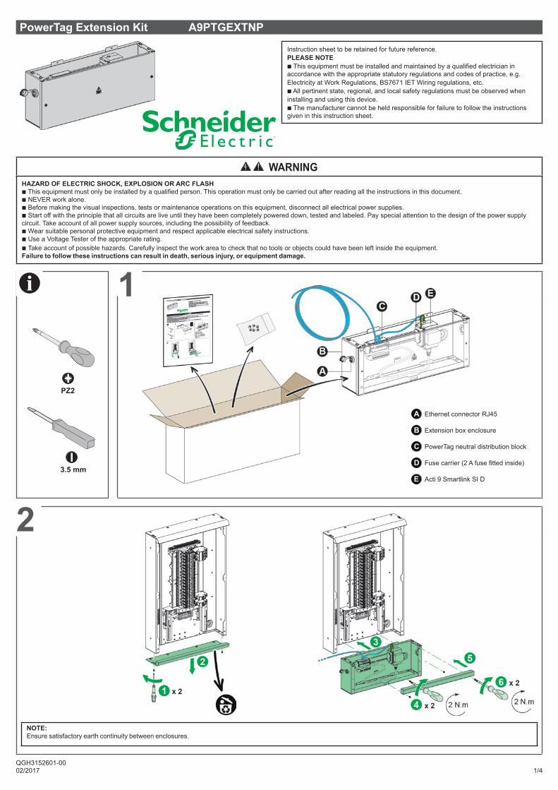
PowerTag Extension Kit A9PTGEXTNP
Instruction sheet to be retained for future reference.PLEASE NOTEb This equipment must be installed and maintained by a qualified electrician in accordance with the appropriate statutory regulations and codes of practice, e.g. Electricity at Work Regulations, BS7671 IET Wiring regulations, etc.b All pertinent state, regional, and local safety regulations must be observed when installing and using this device.b The manufacturer cannot be held responsible for failure to follow the instructions given in this instruction sheet.
WARNINGHAZARD OF ELECTRIC SHOCK, EXPLOSION OR ARC FLASHb This equipment must only be installed by a qualified person. This operation must only be carried out after reading all the instructions in this document.b NEVER work alone.b Before making the visual inspections, tests or maintenance operations on this equipment, disconnect all electrical power supplies.b Start off with the principle that all circuits are live until they have been completely powered down, tested and labeled. Pay special attention to the design of the power supply circuit. Take account of all power supply sources, including the possibility of feedback.b Wear suitable personal protective equipment and respect applicable electrical safety instructions.b Use a Voltage Tester of the appropriate rating.b Take account of possible hazards. Carefully inspect the work area to check that no tools or objects could have been left inside the equipment.Failure to follow these instructions can result in death, serious injury, or equipment damage.
1
A Ethernet connector RJ45
B Extension box enclosure
C PowerTag neutral distribution block
D Fuse carrier (2 A fuse fitted inside)
E Acti 9 Smartlink SI D
NOTE:Ensure satisfactory earth continuity between enclosures.
C
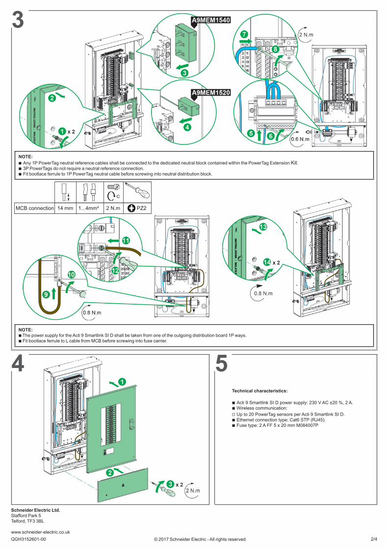
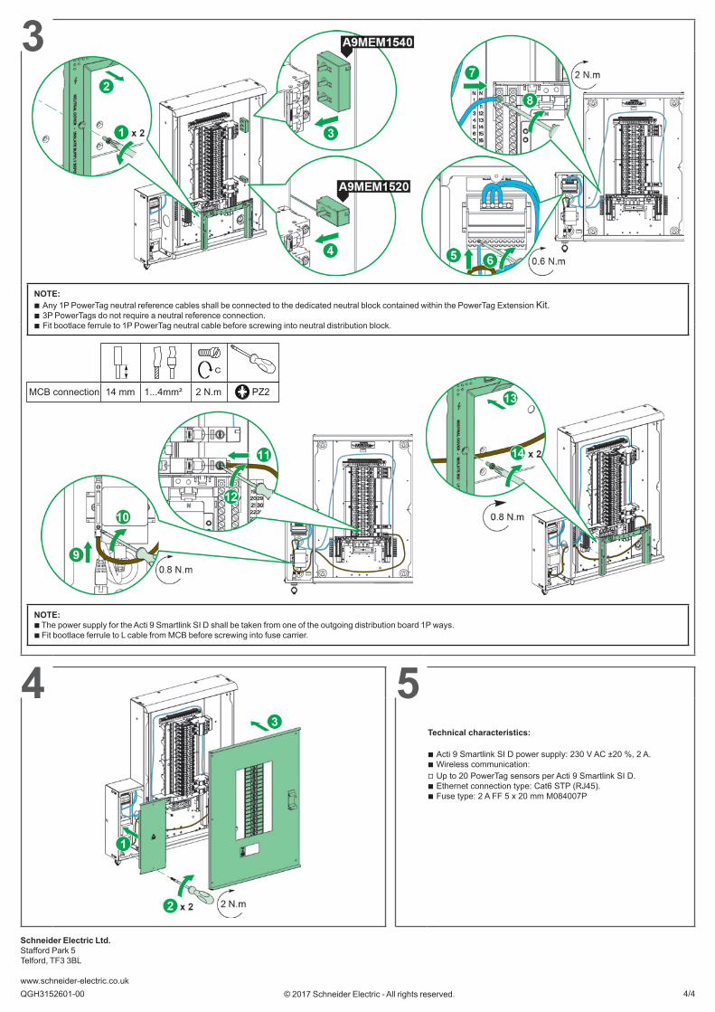
14 mmMCB connection 1...4mm² 2 N.m PZ2
Schneider Electric Ltd.Stafford Park 5Telford, TF3 3BL www.schneider-electric.co.ukQGH3152601-00 2/4© 2017 Schneider Electric - All rights reserved.
3
v
NOTE:b The power supply for the Acti 9 Smartlink SI D shall be taken from one of the outgoing distribution board 1P ways.b Fit bootlace ferrule to L cable from MCB before screwing into fuse carrier.
54 Ethernet connection
NOTE: b Any 1P PowerTag neutral reference cables shall be connected to the dedicated neutral block contained within the PowerTag Extension Kit. b 3P PowerTags do not require a neutral reference connection. b Fit bootlace ferrule to 1P PowerTag neutral cable before screwing into neutral distribution block.
Technical characteristics:
b Acti 9 Smartlink SI D power supply: 230 V AC ±20 %, 2 A. b Wireless communication: v Up to 20 PowerTag sensors per Acti 9 Smartlink SI D. b Ethernet connection type: Cat6 STP (RJ45). b Fuse type: 2 A FF 5 x 20 mm M084007P
PZ23.5 mm
10
10
02/2017 3/4QGH3152601-00
2
1
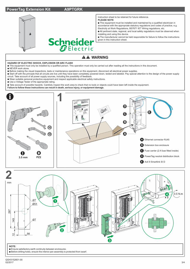
PowerTag Extension Kit A9PTGRK
Instruction sheet to be retained for future reference.PLEASE NOTEb This equipment must be installed and maintained by a qualified electrician in accordance with the appropriate statutory regulations and codes of practice, e.g. Electricity at Work Regulations, BS7671 IET Wiring regulations, etc.b All pertinent state, regional, and local safety regulations must be observed when installing and using this device.b The manufacturer cannot be held responsible for failure to follow the instructions given in this instruction sheet.
NOTE:b Ensure satisfactory earth continuity between enclosures. b Before drilling holes, ensure the interior pan assembly is protected from swarf.
WARNINGHAZARD OF ELECTRIC SHOCK, EXPLOSION OR ARC FLASHb This equipment must only be installed by a qualified person. This operation must only be carried out after reading all the instructions in this document.b NEVER work alone.b Before making the visual inspections, tests or maintenance operations on this equipment, disconnect all electrical power supplies.b Start off with the principle that all circuits are live until they have been completely powered down, tested and labeled. Pay special attention to the design of the power supply circuit. Take account of all power supply sources, including the possibility of feedback.b Wear suitable personal protective equipment and respect applicable electrical safety instructions.b Use a Voltage Tester of the appropriate rating.b Take account of possible hazards. Carefully inspect the work area to check that no tools or objects could have been left inside the equipment.Failure to follow these instructions can result in death, serious injury, or equipment damage.
mm
A Ethernet connector RJ45
B Extension box enclosure
C Fuse carrier (2 A fuse fitted inside)
D PowerTag neutral distribution block
E Acti 9 Smartlink SI D
Schneider Electric Ltd.Stafford Park 5Telford, TF3 3BL www.schneider-electric.co.ukQGH3152601-00 4/4© 2017 Schneider Electric - All rights reserved.
3
v
NOTE:b The power supply for the Acti 9 Smartlink SI D shall be taken from one of the outgoing distribution board 1P ways.b Fit bootlace ferrule to L cable from MCB before screwing into fuse carrier.
54 Ethernet connection
Technical characteristics:
b Acti 9 Smartlink SI D power supply: 230 V AC ±20 %, 2 A. b Wireless communication: v Up to 20 PowerTag sensors per Acti 9 Smartlink SI D. b Ethernet connection type: Cat6 STP (RJ45). b Fuse type: 2 A FF 5 x 20 mm M084007P
NOTE: b Any 1P PowerTag neutral reference cables shall be connected to the dedicated neutral block contained within the PowerTag Extension Kit. b 3P PowerTags do not require a neutral reference connection. b Fit bootlace ferrule to 1P PowerTag neutral cable before screwing into neutral distribution block.
C
14 mmMCB connection 1...4mm² 2 N.m PZ2