Embed Size (px)
Citation preview

PowerIT Liquid Filled Single Phase Padmounted Transformers10-250 kVA
IndustrialIT
enabled
X62082-Brochure 8/15/03 10:09 AM Page 1

X62082-Brochure 8/15/03 10:09 AM Page 2

ABB 3
Introduction to ABB
ABB is a global leader in power and automa-tion technologies that enable utility and indus-try customers to improve their performancewhile lowering their environmental impact.
Distribution Transformers
ABB Distribution Transformers provide themost complete line of padmounted transform-ers to meet the applications of any distributionsystem. We are a dominant force in the indus-try. We lead the way with the introduction of new products and services for the ever-changing distribution transformer industry.
We can offer cost-effective solutions for powerdistribution. We support our industry with acommitment to product development. We utilizethe latest manufacturing technology to maintainstate-of-the-art quality and productivity. Largevertical integration allows us to ship high qualityproducts in the shortest possible productioncycle. We are in alliances with major utilities andbusinesses around the world providing productsand services to meet all their needs.
ABB will continue to build on a heritage ofquality, customer satisfaction and technology,and capitalize on its resources, to maintain itsposition as the number one supplier of trans-formers in the industry.
IndustrialIT
Industrial IT is the ABB name for our commit-ment to real-time integrated solutions forpower, automation, and information.
Our Quality Policy
Total customer satisfaction through continualprocess improvement.
Our Values
Our values guide us in how we go about meet-ing our vision and mission.
Customer Success – We seek to provide solu-tions for mutual competitive advantage. We setthe highest standards for quality, meet deliverycommitments and provide high value.
Quality Excellence – We want to be recognizedas a company that exceeds our customers’expectations.
ABB Quality Strategy
Start with a focus on the customer.
Measure what is important.
Define a benchmark for “highest standard for quality.”
Have a means to dramatically improve perfor-mance against the benchmark.
X62082-Brochure 8/15/03 10:09 AM Page 3

4 ABB
A single phase, multi-service, low profile padmounted transformer.
The Mini-Pak is designed for cross feed (Type 2) loop feed orradial feed on a grounded wye, underground distributionsystem. It can be furnished in a complete line of ratings andin a wide range of configurations to meet the reliability,safety and operating requirements of any distribution system.
The Mini-Pak meets the following industry standards:ANSI C57.12.00 NEMA TR-1ANSI C57.12.25 WUG 2.13, Rev. 4ANSI C57.12.28 ANSI C57.12.29ANSI C57.12.70 ANSI C57.12.80ANSI C57.12.90 ANSI C57.91
Ratings @ 65º C Rise:kVA: 10, 15, 25, 37-1/2, 50, 75, 100, 167HV: 4160GY/2400 through 34500GY/19920VBIL: 60, 75, 95, 125 kV LV: 240/120, 480/240, 277 V60 hertz standard, 50 hertz optional
Standard Features:1. Equipped with two universal high voltage bushing wells
for loop feed. (Only one bushing well is provided forradial feed.)
2. A flip-top hood and heavy duty 3/8", removable stainlesssteel hinge pins provide safe and durable service.
3. A recessed locking assembly with padlock provisionsand a penta-head locking bolt is standard for tamper-resistant operation. A hex-head locking bolt is available.
4. All tanks are constructed of heavy gauge steel. Tankseams are welded and each unit is pressure tested andinspected for leaks prior to shipment. In addition, allsingle phase transformers are supplied with:a) 5/8" -11 stainless steel lifting bossesb) Oil level/fill plugc) Oil drain plugd) Self-actuating pressure relief devicee) Two ground bosses,1/2" -13 NC tapped hole,
7/16" deep5. The front sill latches with the flip-top hood, is attached
on the side of the tank and is removable.6. The high voltage universal bushing wells are externally
clamped and removable. A parking stand between thebushing wells is provided for attachment of bushingaccessories.
7. Externally clamped low voltage bushings with contact nuts.8. Tamper-resistant design that exceeds ANSI C57.12.28.9. NEMA safety labels.
10. Nameplate.11. The paint finish process applies a durable, corrosion
resistant finish to the product. The finish meets orexceeds all the performance requirements of ANSI
C57.12.28. The multi-step process includes an epoxyprimer uniformly applied by cationic electrodepositionand a urethane top coat.
Optional Accessories:Overcurrent Protection• An internal primary protective link to remove the trans-
former from the system in the event of an internal fault.• A secondary breaker provides protection against
secondary overloads and short circuits.• An oil-immersed bayonet-type fuse link to remove the
transformer from the system in case of an internal fault(fault sensing) or secondary short or overload (overloadsensing). This fuse is a drawout design and is supplied inseries with an isolation link. A drip plate is provided toprevent oil from dripping onto the bushing or elbow.
• A current limiting fuse mounted in a dry well loadbreakcanister.• The high interrupting rating of the CL fuse permits
its use on systems where the available fault currentexceeds the ratings of normal expulsion fuses.
• A partial range current limiting fuse mounted under oilwith the transformer tank.• An explusion fuse is supplied in series with the partial
range CL fuse.• Available at 95 and 125 kV BIL.
Switching• Externally-operated tap changer. • Externally-operated dual voltage switch. • Externally-operated loadbreak oil rotary (LBOR) switch. Primary Connection• Universal bushing wells (standard) and loadbreak inserts.• Integral (one piece) loadbreak bushings.Secondary Connections• Copper studs with contact nuts (standard).• Copper studs with rotatable spades.
• Four-hole, NEMA type, tin-plated copper alloy spade.• Four-hole, in line, tin-plated copper alloy spade.
Miscellaneous• Cleats for anchoring sill to pad.• Stainless steel transformer (304 or 400 CB).• Stainless steel (“Mini-Skirt”) at base of carbon steel tank.• Composite hood, one piece enclosure • Conduit hole (not available with composite hood).• Provisions for fault indicator.
Minimum/Maximum Design Dimensions(Actual dimensions will vary according to voltage, loss evalu-ation, and accessories.)
MTR A B C DMin. 24 32 30.5 14.25Max. 42 44 46.5 19.25
MTR Mini-Pak Single PhasePadmounted Transformer
Recommended Pad Dimensions
Design Dimensions:Approximate dimensions. Dimensions are in inches.
Side View
SILLFLANGETYP.
1.25"
A
B
SILL
1.00"
1.25"
D
C
FLANGE
C+6"
B+6"
CABLE OPENING
5.0"
5.0"
Front View
X62082-Brochure 8/15/03 10:09 AM Page 4

ABB 5
Recommended Pad Dimensions
Design Dimensions:Approximate dimensions. Dimensions are in inches.
Side View
SILLFLANGETYP.
1.25"
A
B
SILL
1.00"
1.25"
D
FLANGE
C+6"
B+6"
CABLE OPENING
5.0"
5.0"
Front View
A single phase, multi-service, low profile padmounted transformer.
The Maxi-Pak is designed for loop or radial feed on agrounded wye, underground distribution system. It isdesigned specifically for customers requiring straight-upfeed (Type 1) rather than cross feed (Type 2).
The Maxi-Pak meets the following industry standards:ANSI C57.12.00 ANSI C57.12.80ANSI C57.12.21 - Live front ANSI C57.12.90ANSI C57.12.25 - Dead front NEMA TR-1ANSI C57.12.28 WUG 2.13, Rev. 4ANSI C57.12.29 ANSI C57.91ANSI C57.12.70
Ratings @ 65º C Rise:kVA: 10, 15, 25, 37-1/2, 50, 75, 100,167, 250HV: 4160GY/2400 through 34500GY/19920V BIL: 60, 75, 95, 125, 150 kV LV: 240/120, 120/240, 480/240,240/480, 277 V60 hertz standard, 50 hertz optional
Standard Features:1. Equipped with two universal high voltage bushing wells
for loop feed. (Only one bushing well is provided forradial feed.)
2. A flip-top hood and heavy duty 3/8", removable stainlesssteel hinge pins provide safe and durable service.
3. A recessed locking assembly with padlock provisionsand a penta-head locking bolt is standard for tamper-resistant operation. A hex-head locking bolt is available.
4. All tanks are constructed of heavy gauge steel. Tankseams are welded and each unit is pressure tested andinspected for leaks prior to shipment. In addition, allsingle phase trans-formers are supplied with:a) 5/8" -11 stainless steel lifting bossesb) Oil level/fill plugc) Oil drain plugd) Self-actuating pressure relief devicee) Two ground bosses, 1/2" -13 NC tapped hole,
7/16" deep5. The front sill latches with the flip-top hood, is attached
on the side of the tank and is removable.6. The high voltage universal bushing wells are externally
clamped and removable. A parking stand between thebushing wells is provided for attachment of bushingaccessories.
7. Externally clamped low voltage bushings with contact nuts.8. Tamper-resistant design that exceeds ANSI C57.12.28.9. NEMA safety labels.
10. Nameplate.11. The paint finish process applies a durable, corrosion
resistant finish to the product. The finish meets or
exceeds all the performance requirements of ANSIC57.12.28. The multi-step process includes an epoxyprimer uniformly applied by cationic electrodepositionand a urethane top coat.
Optional Accessories:Overcurrent Protection• An internal primary protective link to remove the trans-
former from the system in the event of an internal fault.• A secondary breaker provides protection against
secondary overloads and short circuits. • An oil-immersed bayonet-type fuse link to remove the
transformer from the system in case of an internal fault(fault sensing) or secondary short or overload (overloadsensing). This fuse is a drawout design and is supplied inseries with an isolation link. A drip plate is provided toprevent oil from dripping onto the bushing or elbow.
• A current limiting fuse mounted in a dry well loadbreakcanister.• The high interrupting rating of the CL fuse permits its
use on systems where the available fault currentexceeds the ratings of normal expulsion fuses.
• A partial range current limiting fuse mounted under oilwith the transformer tank. • An explusion fuse is supplied in series with the partial
range CL fuse.• Available at 95, 125 and 150 kV BIL.
Switching• Externally-operated tap changer. • Externally-operated dual voltage switch. • Externally-operated loadbreak oil rotary (LBOR) switch. Primary Connection• Universal bushing wells (standard) and loadbreak inserts.• Integral (one piece) loadbreak bushings.Secondary Connections• Copper studs with contact nuts (standard).• Copper studs with rotatable spades.
• Four-hole, NEMA type, tin-plated copper alloy spade.• Four-hole, in line, tin-plated copper alloy spade.
• Cable lead secondary. Miscellaneous• Cleats for anchoring sill to pad.• Stainless steel transformer (304 or 400 CB).• Stainless steel (“Mini-Skirt”) at base of carbon steel tank.• Conduit hole.• Provisions for fault indicator.
Minimum/Maximum Design Dimensions(Actual dimensions will vary according to voltage, loss evaluation, and accessories.)
MTR A B C DMin. 32 32 30.5 14.25Max. 42 44 46.5 19.25
MTR Maxi-Pak Single PhasePadmounted Transformer
X62082-Brochure 8/15/03 10:09 AM Page 5

6 ABB
A single phase, single service, low profile distribution pad-mount transformer available in loop or radial feed.
Designed to aesthetically, safely and economically provideunderground electrical service to single loads, particularly,rural residences, farms and ranches.
The Micro-pak meets the following industry standards:ABB padmounted distribution transformers meet the follow-ing industry standards:ANSI C57.12.00 ANSI C57.12.80ANSI C57.12.25 NEMA TR-1ANSI C57.12.28 WUG 2.13, Rev. 4ANSI C57.12.29 ANSI C57.91ANSI C57.12.70 ANSI C57.12.90
Ratings @ 65º C Rise:kVA: 10, 15, 25, 37-1/2, 50HV: 4160GY/2400 through 24940GY/14400VBIL: 60, 75, 95, 125 kV LV: 240/120, 480/240, 277 V, 120/2401,240/480160 hertz standard, 50 hertz optional
Standard Features:1. Equipped with two universal high voltage bushing wells
for loop feed. (Only one bushing well is provided forradial feed.)
2. A flip-top hood and heavy duty 3/8", removable stainlesssteel hinge pins provide safe and durable service.
3. A recessed locking assembly with padlock provisionsand a penta-head locking bolt is standard for tamper-resistant operation. A hex-head locking bolt is available.
4. All tanks are constructed of heavy gauge steel. Tankseams are welded and each unit is pressure tested andinspected for leaks prior to shipment. In addition, allsingle phase transformers are supplied with:a) 5/8" -11 stainless steel lifting bossesb) Oil level/fill plugc) Oil drain plugd) Self-actuating pressure relief devicee) Two ground bosses, 1/2" -13 NC tapped hole,
7/16" deep5. The front sill latches with the flip-top hood, is attached
on the side of the tank and is removable.6. The high voltage universal bushing wells are externally
clamped and removable. A parking stand between thebushing wells is provided for attachment of bushingaccessories.
7. Externally clamped low voltage bushings with contact nuts.8. Tamper-resistant design that exceeds ANSI C57.12.28.9. NEMA safety labels.
10. Nameplate.11. The paint finish process applies a durable, corrosion
resistant finish to the product. The finish meets orexceeds all the performance requirements of ANSIC57.12.28. The multi-step process includes an epoxyprimer uniformly applied by cationic electrode positionand a urethane top coat.
Optional Accessories:Overcurrent Protection• An internal primary protective link to remove the trans-
former from the system in the event of an internal fault.• An oil-immersed bayonet-type fuse link to remove the
transformer from the system in case of an internal fault(fault sensing) or secondary short or overload (overloadsensing). This fuse is a drawout design and is supplied inseries with an isolation link. An optional drip plate is pro-vided to prevent oil from dripping onto the bushing orelbow.
Primary Connection• Universal bushing wells (standard) and loadbreak inserts.• Integral (one-piece) loadbreak bushings.Secondary Connections• Copper studs with contact nuts (standard).• Copper studs with rotatable spades.• Four-hole, NEMA type, tin-plated copper alloy spade.• Four-hole, in line, tin-plated copper alloy spade.• Cable lead secondary. Miscellaneous• Cleats for anchoring sill to pad.• Polypad mounting base. • Stainless steel transformer (304 or 400 CB).• Stainless steel (“Mini-Skirt”) at base of carbon steel tank.• Conduit hole.• Provisions for fault indicator.
Minimum/Maximum Design Dimensions(Actual dimensions will vary according to voltage, loss evalu-ation, and accessories.)
MTR A B C DMin. 24 24 30.5 14.25Max. 26 24 35.5 16.25
MTR Micro-Pak Single PhasePadmounted Transformer
1Available only with cable lead secondary
Recommended Pad Dimensions
Design Dimensions:Approximate dimensions. Dimensions are in inches.
Side View
SILLFLANGETYP.
1.25"
A
B
SILL
1.00"
1.25"
D
C
FLANGE
C+6"
B+6"
CABLE OPENING
5.0"
5.0"
Front View
X62082-Brochure 8/15/03 10:09 AM Page 6

ABB 7
The innovative composite hood is a one-piece, compressionmolded replacement of the steel hood and sill on the singlephase padmounted transformer. The composite is made offiberglass reinforced, non-conductive, thermosetting resin. Itlatches at a single point to the tank. The system providessignificant operational advantages including more cost effec-tive corrosion protection than stainless steel. It is designedto aesthetically, safely and economically provide under-ground electrical service.
The Composite Hood transformer has passed all ANSIC57.12.28 tamper resistance tests, impact tests at –20º F andtests simulating a high voltage elbow failure. The design meetsC57.12.25. Additional tests were performed to insure that theenclosure would withstand the abuse of string weed trimmersand impact from lawn equipment. It is RUS accepted.
The Composite Hood transformer meets the following industry standards:ANSI C57.12.00 NEMA TR-1ANSI C57.12.25 ANSI C57.12.28ANSI C57.12.29 WUG 2.13, Rev. 4ANSI C57.12.70 ANSI C57.91ANSI C57.12.80 ANSI C57.12.90
Ratings @ 65º C Rise:kVA: 10, 15, 25, 37-1/2, 50, 75, 100HV: 4160GY/2400 through 34500GY/19920V LV: 240/120, 480/240, 277 V60 hertz standard, 50 hertz optional
Standard Features:1. The hood is a one-piece, compression molded compos-
ite of fiberglass reinforced, non-conductive, thermo-set-ting resin. The material is corrosion and scratch resistant.
2. The elimination of the traditional metal sill providesimproved access to the entire cable area of the trans-former.
3. During installation, alignment of the transformer on thesupporting pad is easier since the composite does nothave a sill.
4. A significant feature is its light weight: about 25 lbs. for acomposite hood compared to 50 lbs. for a steel hood.Due to its light weight, a single operator may open andclose the composite enclosure with little effort. In anergonomic study, it was shown that the compositeenclosure reduced the resultant stress by 10-14% for allbody types and lifting positions compared to the tradi-tional steel hood design.
5. Strategically located stiffening ribs help provide thestrength, stiffness and flexibility that is required to meetthe design and function criteria.
6. A recessed lock pocket and handle are convenientlylocated at the front, top center of the enclosure and a stainless steel latch plate with attached lock bolt is fastened to the lock pocket.
7. At the tank and enclosure interface, a tongue andgroove arrangement insures tamper resistance whenclosed and locked.
8. The composite enclosure is non-conductive providingexcellent insulation protection from exposed energizedcables and bushings inside the cable compartment. Theenclosure acts as a shield from animals and insects thatmay hide in the cable area.
9. In the case of moderate impact, the composite enclosureis more flexible than steel and less prone to damage.
10. All tanks are constructed of heavy gauge steel. Tankseams are welded and each unit is pressure tested andinspected for leaks prior to shipment. In addition, alltransformers are supplied with:a) 5/8" -11 stainless steel lifting bossesb) Oil level/fill plugc) Oil drain plugd) Self-actuating pressure relief devicee) Two ground bosses, 1/2" -13 NC tapped hole,
7/16" deep11. The high voltage universal bushing wells are externally
clamped and removable. A parking stand between thebushing wells is provided for attachment of bushingaccessories.
12. Externally clamped low voltage bushings with contact nuts.13. NEMA safety labels. (Internal label not in standard location.)14. Nameplate.15. The paint finish process applies a durable, corrosion
resistant finish to the product. The finish meets orexceeds all the performance requirements of ANSIC57.12.28. The multi-step process includes an epoxyprimer uniformly applied by cationic electrodepositionand a urethane top coat.
Optional Accessories: Overcurrent Protection• An internal primary protective link to remove the trans-
former from the system in the event of an internal fault.• An oil-immersed bayonet-type fuse link to remove the
transformer from the system in case of an internal fault(fault sensing) or secondary short or overload (overloadsensing). This fuse is a drawout design and is supplied inseries with an isolation link. A drip plate is provided toprevent oil from dripping onto the bushing or elbow.
Primary Connection• Universal bushing wells (standard) and loadbreak inserts.• Integral (one-piece) loadbreak bushings.Secondary Connections• Copper studs with contact nuts (standard).• Copper studs with rotatable spades.• Four-hole, NEMA type, tin-plated copper alloy spade.• Four-hole, in line, tin-plated copper alloy spade.• Cable lead secondary. Miscellaneous• Stainless steel transformer (304 or 400 CB) tank.• Stainless steel 400CB (“Mini-Skirt”) at base of carbon steel
tank.
A conduit hole and a fault indicator cannot be provided onthe composite hood. Internal stencils and decals cannot beprovided.
Anchoring cleats are not provided. The unit may beanchored from the front edges of the tank.
Composite Hood Single PhasePadmounted Transformer
X62082-Brochure 8/15/03 10:09 AM Page 7
Minimum/Maximum Design Dimensions(Actual dimensions will vary according to voltage, loss evalu-ation, and accessories.)
A B C DMin. 24 32 33 17Max. 24 34 42 17
Standard Design Information
kVA A B C D Wt.10-15 24 32 33 17 68525 24 32 33 17 72537.5 24 32 34 17 77550 24 34 36 17 86575 24 34 40 17 985100 24 34 42 17 1100
Note: For 75 and 100 kVA add 9" for cooling fins.
8 ABB
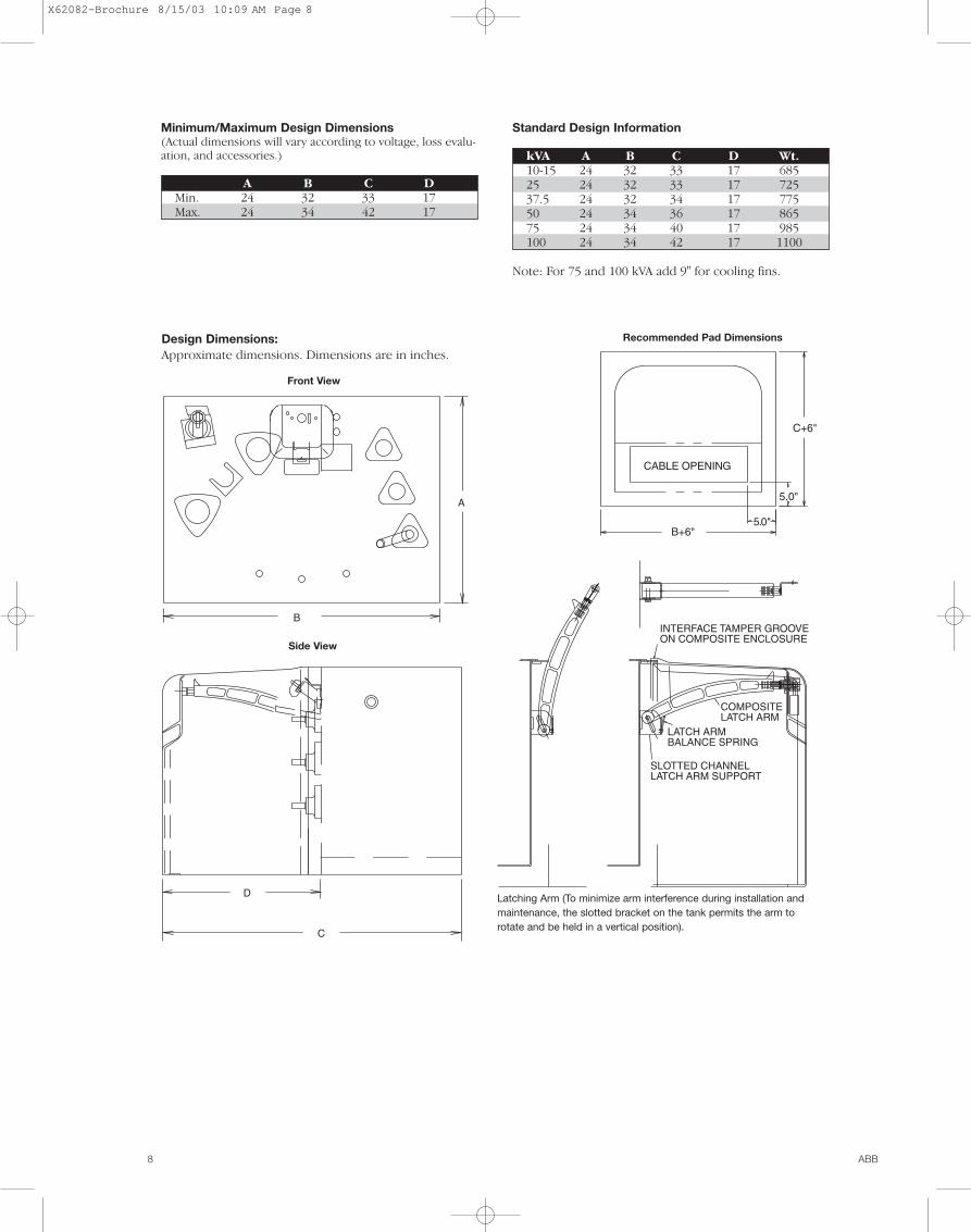
Recommended Pad Dimensions
Latching Arm (To minimize arm interference during installation andmaintenance, the slotted bracket on the tank permits the arm torotate and be held in a vertical position).
Side View
Design Dimensions:Approximate dimensions. Dimensions are in inches.
A
B
D
C
C+6"
B+6"
CABLE OPENING
5.0"
5.0"+
+
SLOTTED CHANNELLATCH ARM SUPPORT
LATCH ARMBALANCE SPRING
COMPOSITELATCH ARM
INTERFACE TAMPER GROOVEON COMPOSITE ENCLOSURE
+
+
+
+
Front View
X62082-Brochure 8/15/03 10:09 AM Page 8

ABB 9
The ABB commitment to manufacture quality distributiontransformers is backed by a series of transformer tests usedto verify conformance to performance characteristics out-lined in the latest revisions of ANSI C57.12.00 and ANSIC57.12.90. These identified tests are also part of the QualitySystem which is audited semi-annually by DET NOSKE VERI-TAS (DNV) to the ISO Standards.
Testing ProgramFactory tests are performed on a transformer to confirmthat it is properly designed and constructed to carry ratedload and that it will withstand the conditions it will beexposed to in service.
Each transformer manufactured by ABB must undergo aseries of tests.
1. Polarity, Phase-Relation, and Ratio2. Demag Test3. Applied Voltage Test of the HV4. Applied Voltage Test of the LV5. Induced Voltage Test6. No-Load (Excitation) Loss and Excitation Current7. Impedance Voltage and Load Loss8. Full Wave Impulse 9. Continuity Check
Test FacilitiesThe multi-station, automated test facilities are operated byprocess control computers. Required interaction with testfloor personnel is minimal with the computers initiating andmonitoring each test, and then analyzing the test resultsfeedback. The computers are programmed to conduct testsaccording to ANSI standards, and according to the ratings ofeach transformer style, the test floor computers will initiateappropriate test setups, compare results with establishedANSI standard limits, and determine acceptance for eachtested unit.
The test results for each unit are recorded and stored oncomputer files for access and analysis.
Polarity, Phase-Relation, and Ratio TestsThese tests verify proper phase-relation (three phase), ratio,and polarity (single phase) of the transformer under test. Topass, a unit must demonstrate the proper polarity or phase-relation and have a turns ratio within one-half of one percentof the nominal voltage ratio.
Demag TestSome transformers require the Demag Test to remove anyresidual magnetism in preparation for an impulse test. Italso serves as a no-load exciting current test. A transformerpasses this test if the exciting current does not exceed thelimit specified for the design of the transformer.
Applied Voltage Test of the HVThis test checks the dielectric integrity of insulation struc-tures between the high voltage and low voltage, andbetween the high voltage and ground. A pass/fail decision ismade by monitoring the test current intensity. If the resultingcurrent is larger than specified normal leakage and capacitivecurrents, the unit is rejected. This test is omitted for trans-formers with a permanently grounded high voltage winding.
Applied Voltage Test of LVThis dielectric test is similar to the Applied Voltage test ofthe high voltage circuitry except that the integrity of insula-tion structures between the low voltage and the high volt-age, and between the low voltage and ground is checked. A pass-fail decision is made by monitoring the test currentintensity. If the resulting current is larger than specified nor-mal leakage and capacitive current, the unit is rejected.
Induced Voltage TestThe principal purpose of this test is to verify the dielectricstrength of turn to turn, layer to layer, phase to phase, andother insulation structures within the transformer windingsby inducing an overvoltage condition (at higher than normalfrequency to avoid saturation of the core). The test currentis monitored, and if it exceeds limits specified for eachtransformer, the unit is rejected.
No-Load Loss and Excitation CurrentThis test measures the no-load (excitation) loss and thetransformer exciting current with rated voltage applied. Ifthe exciting current and/or the no-load loss exceed the lim-its specified, the transformer is rejected.
Impedance Voltage and Load LossThis test measures the load loss and the impedance voltageat rated current. The load loss and the impedance voltagemust be within specified limits.
Full Wave ImpulseThe impulse test is one of several tests designed to verifythe dielectric strength of the many insulation structureswithin the distribution transformer against line voltagesurges. It is performed to comply with ANSI standards andfor quality assurance. The change in the ANSI standard in1993 required all manufacturers to install fault detectionsensitive enough to detect a single turn short.
Continuity CheckThis test is performed on all transformers to verify trans-former circuit and component integrity. This test is per-formed with an ohmmeter to verify that the internal wiringis correct.
The transformer’s nameplate is compared to manufacturinginformation for style, serial number, kVA, HV rating, LV rat-ing, tap voltages, impedance, conductor materials and coilBIL rating. The bushings, electrical accessories, and fuses areverified.
Distribution Transformer Testing
X62082-Brochure 8/15/03 10:09 AM Page 9

10 ABB
Special TestsSome tests are performed at the option of the customer.
Sound TestingANSI standards define the required sound levels for trans-former but some customers specify reduced sound levels.The sound generated by a transformer is affected by the coregeometry, flux density, tank design, and the quality of assem-bly of all the transformer components into a completed unit.Sound tests are made with the unit powered at 100% and110% of rated voltage under no-load conditions.
Temperature TestsCore losses and coil losses are the primary sources of heat-ing within the transformer. Our transformers are guaranteedto have an average coil winding temperature of no morethan 65° C rise over ambient air temperature when operatedat rated voltage and load conditions.
The temperature test is performed to determine the ther-mal characteristics of the transformer and to verify that theyare within design limits.
CalibrationTest equipment is calibrated on a scheduled basis by trainedtechnicians. Calibration records are maintained in accordancewith the Quality System procedures. These are audited semi-annually by DNV in accordance with ISO Standards.
Short Circuit Withstand CapabilitiesDistribution transformers are subjected to external short circuits on the secondary side. Such external faults candevelop on the service line, in the house wiring or in con-nected loads due to numerous environmental reasons.These faults can be line-to-ground, double line-to-ground orline-to-line.
To meet these operating conditions, the American NationalStandard Institute (ANSI) has set standards concerning shortcircuit withstand capability. These standards require that dis-tribution transformers shall be designed and constructed towithstand the mechanical and thermal stresses produced bythese external short circuits.
The current standards relating to short circuit strength areANSI C57.12.00 which sets the short circuit withstand require-ments for distribution transformers and ANSI C57.12.90which provides procedures for short circuit testing.
For distribution transformers, the magnitude of the shortcircuit current, the numbers of short-circuit tests and theduration of each short circuit test are defined by ANSI stan-dards as follows.
A. Magnitude
Single ThreePhase Phase Withstand
Category kVA kVA Capability*I 5-25 15-75 40
37.5-100 112.5-300 35
167-500 500 25
II 750-2500 1/ZT**
*Base current (Symmetrical) per unit for all distribution transformerswith secondary rated 600 V and below.
**The short circuit current will be limited by the transformer impedance only.
B. Number of TestsEach phase of the transformer shall be subjected to a totalof six tests, four with symmetrical fault currents and twowith asymmetrical fault currents.
C. Duration of Short Circuit TestsWhen short circuit tests are performed the duration of eachtest shall be 0.25 s except that one test satisfying the symmet-rical current requirement shall be made for a longer durationon distribution transformers. The duration of the long test ineach case shall be as follows:
Category I:T=1250/I2
Where T is the duration in seconds,And I=Isc/IR=symmetrical short circuit current, in multiples ofnormal base current except I shall not exceed the maximumsymmetrical current magnitudes listed in A.Where Isc=IR/ZT=symmetrical short circuit current, in rmsamperesIR=rated current on the given tap connection, in rmsamperesZT=transformer impedance on the given tap connection inper unit on the same apparent power base as IR
Category II:T=1.0 second
Criteria of Satisfactory PerformanceAccording to ANSI Standards a unit is considered to havepassed the test if it passes a visual inspection and dielectrictests. Recommended additional checks include examinationof wave shape of terminal voltage and current, leakageimpedance measurement and excitation current test. (Referto ANSI C57.12.90.)The standard allows the following variations in the leakageimpedance:
ZT (Per Units) Percentage Variation0.0299 or less 22.5-500 (ZT)0.0300 or more 7.5
ZT=per unit impedance of the transformer
X62082-Brochure 8/15/03 10:09 AM Page 10

ABB 11
ABB utilizes a multi-step process to apply a corrosion resis-tant finish to transformers. The materials and processesused are designed to protect against the effects of abrasion,sunlight, rural and industrial atmospheres, and humidity.Each carefully controlled process step has a specific pur-pose, and each step builds on the previous steps to formthe complete protection system that ensures that our trans-formers meet ANSI functional paint specification guidelines.
Paint Process ProcedureTransformer parts receive the following steps of surfacepreparation prior to painting.1. Shotblast: All parts are centrifugally blast cleaned to remove
welding by-products and provide a uniform surface profile forbetter, more consistent adhesion and corrosion protection.
2. Alkaline wash cleaner: Removes mill oils, drawing oils,and shop soils that could interfere with good adhesion.
3. Water rinse.4. Zinc phosphate coating: Provides a firm anchor for good
paint adhesion and provides resistance to underfilm corro-sion should the paint film be damaged, exposing bare metal.
5. Water rinse.6. Deionized water rinse: Removes any ionic contamination
to prepare for first application of paint.
This entire cleaning and pretreating process is automaticand conveyorized with all chemicals applied by spray. Thepretreatment system combines the latest in cleaning tech-nology such as DI rinses and zinc phosphate over shotblast-ing in a tried and true format to provide the best possiblepretreatment before paint is applied.
One of the keys to effectiveness of the ABB paint finish sys-tem is the primer. The green epoxy primer is applied bycationic electrodeposition – a dip process in which positivelycharged primer particles are attracted to grounded parts(cathodes). This method applies a very uniform, pinhole-freecoating which penetrates and thoroughly coats all parts. Thisis a highly effective process for coating parts with difficultgeometry. The process utilizes practically 100% of the primerpaint, and since the primer is water borne OSHA and EPAemission standards are met. The primer is free of lead andchrome. After rinsing, parts are cured in an oven in prepara-tion for the next step.
After the transformer is assembled, a final coating of two-com-ponent urethane paint is spray applied for color and additionalfilm build. The final coat provides the weatherability necessaryto protect the unit from sunlight and maintain its appearance.
SummaryThe ABB paint system utilizes advanced techniques andmaterials to provide a superior finish system on pad-mounted distribution transformers. Each step in the processis specifically designed to maximize finish performancewhile minimizing waste to provide the best possible combi-nation of performance and cost.
Paint Finish Process
Paint Finish Specifications and Test ResultsParameter Test Method Specification Typical ABB Value
Total exterior film build Elcometer 256NF 3.0 mil min. 3.5 mils
Salt fog 1500 hrs. ASTM B117 6 rating per ASTM 7 rating per ASTMD1654, no blisters D1654, no blisters
Adhesion ASTM D3359 100% 100%Method A or B
Humidity 1000 hrs. ASTM D4585 No blisters, No blisters,@45c 1 pencil hardness no softening
Impact, 80 InLb ASTM D2794/ No red rust No red rustASTM B117 after 24 hrs. after 24 hrs.
Oil resistance Immerse in 100c No loss of adhesion, No loss of adhesion, Oil for 72 hrs. no blisters no blisters
QUV, 500 hrs. ASTM G53/D523 50% loss of gloss, no 40% loss of gloss, nocracks, no crazing cracks, no crazing
Abrasion, 3000 cycles ASTM D4060 No red rust after No red rust after24 hrs. 24 hrs.
Gravelometer, 60 PSI ASTM 3170/ After 24 hrs. red rust No red rust SAE J400 in chips to not exceed in chips
4B rating
QUV/SCAB, 15 cycles ASTM G53 6 rating per ASTM 7 rating per ASTM D1654, no blisters D1654, no blisters
Paint meets or exceeds ANSI C57.12.28, C57.12.29 and EEMAC Y1-2, Canadian Standard.
X62082-Brochure 8/15/03 10:09 AM Page 11

ABB Inc.Distribution Transformers500 West Highway 94Jefferson City, MO 65101Phone 573-634-2111Fax 573-659-6275e-mail:www.abb.com/distributiontransformers
1LU
J460
100-
LTE
ISO CertifiedJuly, 2003
X62082-Brochure 8/15/03 10:09 AM Page 12