Embed Size (px)
Citation preview

Technical Data
PowerFlex 700 Adjustable Frequency AC Drive
Topic Page
Product Overview 2
Certifications and Specifications 7
Design Considerations 12
Drive, Fuse and Circuit Breaker Ratings 24
Cable Recommendations 33
Power Wiring 34
I/O Wiring 44
Mounting 49
Dimensions and Weights 53
PowerFlex 700 Packaged Drives 77
Drive Options 78

2 Rockwell Automation Publication 20B-TD001H-EN-P - July 2014
PowerFlex 700 Adjustable Frequency AC Drive
Additional ResourcesThese documents contain additional information concerning related products from Rockwell Automation.
You can view or download publications at http://www.rockwellautomation.com/literature/. To order paper copies of technical documentation, contact your local Allen-Bradley distributor or Rockwell Automation sales representative.
Product OverviewThe PowerFlex 700 AC drive offers outstanding performance in an easy-to-use drive that you have come to expect from Rockwell Automation. This world-class performance comes in a small and competitively priced package. The PowerFlex 700 AC drive is designed to control three-phase induction motors in applications with requirements ranging from the simplest speed control to the most demanding torque control. The drive has volts per hertz, sensorless vector and vector control. Vector control includes Allen-Bradley’s patented Force™ Technology which provides world class motor control.
Flexible Packaging and Mounting
• IP20, NEMA / UL Type 1 – For conventional mounting inside or outside a control cabinet. Conduit plate is removable for easy installation and replacement without disturbing conduit.
• IP54, NEMA / UL Type 12 – Stand-alone, wall mount drives are available for dust tight applications with power ratings from 75 to 200 Hp (Frames 5 & 6).
• IP54, NEMA / UL Type 12 – Flange mount drives with an IP00, NEMA / UL Type Open front. These can be installed in a user supplied cabinet to meet IP54, NEMA / UL Type 12. This allows the majority of heat to be exhausted out the back of the cabinet while keeping the cabinet protected. Power ratings range from 75 to 700 Hp (Frames 5…10).
• Zero Stacking™ – Frame 0…6 drives can be mounted next to each other with no reduction of surrounding air temperature rating (50°C). This unique bookshelf design also allows access to one drive without disturbing another.
Resource Description
PowerFlex 700 Adjustable Frequency AC Drive Installation Instructions – Frames 0…6, publication 20B-IN0019 Provides detailed information about installation and start-up.
PowerFlex 700 Adjustable Frequency AC Drive Installation Instructions – Frames 7…10, publication 20B-IN0014
PowerFlex 700 Standard Control User Manual, publication 20B-UM001 Provides detailed information on:• Parameters and programming• Faults, alarms, and troubleshooting
PowerFlex 700 Vector Control User Manual (v4.001 & up), publication 20B-UM002
PowerFlex 70 and PowerFlex 700 Reference Manual, publication PFLEX-RM001 Provides detailed application specific information for programming and configuring the PowerFlex 700 drive.
PowerFlex 70 Enhanced Control and PowerFlex 700 Vector Control Reference Manual, publication PFLEX-RM004
Wiring and Grounding Guidelines for Pulse Width Modulated (PWM) AC Drives, publication DRIVES-IN001 Provides basic information needed to properly wire and ground PWM AC drives.
Safety Guidelines for the Application, Installation and Maintenance of Solid State Control, publication SGI-1.1 Provides general guidelines for the application, installation, and maintenance of solid-state control.
Preventive Maintenance of Industrial Control and Drive System Equipment, publication DRIVES-TD001 Provides a guide to performing preventive maintenance.
Guarding Against Electrostatic Damage, publication 8000-4.5.2 Provides practices for guarding against electrostatic damage (ESD).
Product Certifications website, http://ab.com Provides declarations of conformity, certificates, and other certification details.

Rockwell Automation Publication 20B-TD001H-EN-P - July 2014 3
PowerFlex 700 Adjustable Frequency AC Drive
Space Saving Hardware Features
• Integral EMC Filtering plus built-in DC bus choke common mode cores and common mode capacitors provides a compact, all-in-one package solution for meeting EMC requirements, including CE in Europe. Frames 0…6 only (Frames 7…10 meet CE when installed per recommendations).
• Internal Communications allow the user to integrate the drive into the manufacturing process. Status indicators for all internal communication options are visible on the cover for easy setup and monitoring of drive communications. Users can easily manage information from shop floor to top floor and seamlessly integrate their complete system as they control, configure and collect data.
• Integral Dynamic Brake Transistor delivers a cost effective means of switching regenerative energy without costly external chopper circuits. These internal transistors are available in power ratings from 0.5 to 200 Hp.
• Internal Dynamic Brake Resistor (up to 25 Hp) requires no extra panel space, and supplies a large amount of braking torque for short periods.
Easy to Use Human Interface ToolsThe PowerFlex 7-Class AC drives provide common Human Interface tools that are familiar and easy to use. These include the LCD Human Interface modules and PC-based configuration tools.
• LCD Human Interface modules provide:– Large and easy to read 7 line x 21 character backlit display– Variety of languages (English, French, German, Italian, Spanish, Portuguese, Dutch)– Alternate function keys for shortcuts to common tasks– “Calculator-like” number pad for fast and easy data entry (Full Numeric version only)– Control keys for local start, stop, speed, and direction– Remote versions for panel mount application
Outstanding Control and PerformanceMultiple motor control algorithms allow performance matched to the application need:
• Volts/Hertz for simple Fan and Pump applications.• Sensorless Vector for high torque production over a wide speed range.• Vector for outstanding torque regulation and excellent low speed/zero
speed performance (w/Vector Control cassette).
The PowerFlex 700 drive's Vector Control uses Allen-Bradley's patented Force™ Technology which provides excellent low-speed performance - whether it is operated with or without feedback. While this industry-leading control provides the highest level of drive performance, it is as easy to use as any general purpose drive available.
0.0
0.5
1.0
1.5
2.0
2.5
3.0
-2 0 2 4 6 8 10 12
Frequency (HZ)
Closed Loop Performance
Open Loop Performance
Torq
ue (P
er-U
nit)
0 2 4 6 8 10 120.0
0.5
1.0
1.5
2.0
2.5
3.0
Frequency (HZ)
Torq
ue (P
er-U
nit)

4 Rockwell Automation Publication 20B-TD001H-EN-P - July 2014
PowerFlex 700 Adjustable Frequency AC Drive
Drives Features• Fast-acting Current Limit and Bus Voltage Regulation result in maximum accel/decel without tripping.• High speed analog inputs improve drive response to torque or speed commands.• Programming flexibility allows parameters to be linked within the drive.• Flying Start delivers smooth and instantaneous connection into rotating loads, regardless of commanded direction,
without the need for any speed feedback.• Integral Process PI Control can eliminate the need for a separate process loop controller.• Inertia Ride-Through offers tripless operation during a prolonged power outage by using the rotating energy stored
in high inertia, low-friction loads.• Position Indexer/Speed Profiler uses a 16 step indexer to provide point-to-point positioning or velocity profiling
based on encoder counts, digital inputs, parameter levels or time.• TorqProve™ assures control of the load when transferring control between the drive and a mechanical brake.• Speed Regulation - Open Loop or Closed Loop
– Slip Compensation delivers a minimum 0.5% speed regulation without feedback hardware.– Droop allows drives to load share without fighting each other.– Encoder Feedback provides up to 0.001% speed regulation for the tightest application requirements.
• Torque Regulation - Open Loop or Closed Loop– Open Loop torque regulation provides ±5% regulation.– Encoder Feedback provides ±2% regulation and the ability to hold full load at zero speed.
Unsurpassed Capability in Network CommunicationsPowerFlex drives are fully compatible with the wide variety of Allen-Bradley DPI™ communication adapters, offering the following benefits:
BACn
et®
Cont
rolN
et™
Devi
ceNe
t™
Ethe
rNet
/IP™
LonW
orks
™
Mod
bus R
TU
PROF
IBUS
™
Rem
ote I
/O(1
)
(1) This item has Silver Series status. For information, refer to http://www.ab.com/silver.
RS48
5 DF1
USB
Description
✔ ✔ ✔ (Unconnected Messaging) permits other network devices (e.g. PanelView™) to communicate directly to a drive without routing the communication through the network scanner.
✔ ✔ ✔ ✔ ✔ ✔ Adapter Routing - Plug PC into one drive and talk to all other Allen-Bradley drives on same network, without being routed through network scanner.
✔ ✔ ✔ ✔ ✔ ✔ ✔ ✔ ✔ ✔ Access to 100% of all parameters over the network.
✔ ✔ ✔ ✔ AutoBaud capability makes initial connections less problematic.
✔ Change of State significantly reduces network traffic by configuring control messages to be sent only upon customer defined states. Very flexible configuration for each node (Example: “reference must change by more than 5%”).
✔ ✔ Peer Control provides master-slave type control between drives, where one or more slave drives (consumers) can run based on the status of a master drive (producer), which can also significantly reduce network traffic.
✔ ADR (Automatic Device Replacement) saves significant time and effort when replacing a drive, by allowing the scanner to be configured to automatically detect a new drive and download the required parameter settings.
✔ ✔ ✔ ✔ ✔ ✔ ✔ ✔ ✔ ✔ Flexible Fault Configuration - Adapters can be programmed to take fault based actions as ramp to stop, coast-to-stop and hold last state, as well as send user configurable logic control and speed reference values. In addition, different actions can be taken based on whether the network experienced a serious problem (broken cable etc.) versus network idle condition (PLC set to “Program”).
Rockwell Automation Publication 20B-TD001H-EN-P - July 2014 5
PowerFlex 700 Adjustable Frequency AC Drive
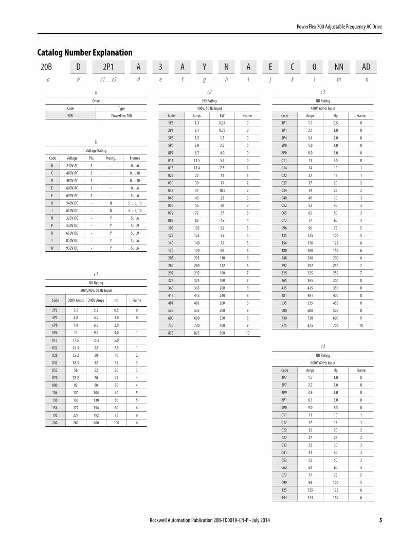
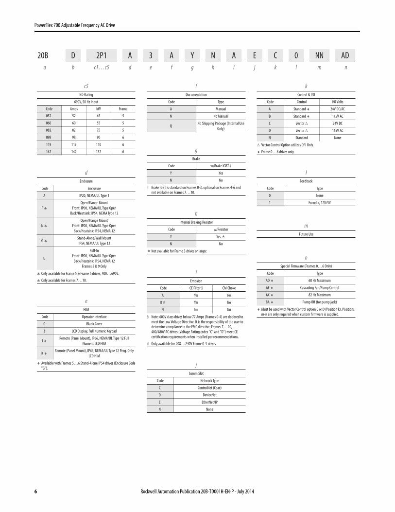
Catalog Number Explanation20B D 2P1 A 3 A Y N A E C 0 NN AD
a b c1…c5 d e f g h i j k l m n
c1ND Rating
208/240V, 60 Hz Input
Code 208V Amps 240V Amps Hp Frame
2P2 2.5 2.2 0.5 0
4P2 4.8 4.2 1.0 0
6P8 7.8 6.8 2.0 1
9P6 11 9.6 3.0 1
015 17.5 15.3 5.0 1
022 25.3 22 7.5 1
028 32.2 28 10 2
042 48.3 42 15 3
052 56 52 20 3
070 78.2 70 25 4
080 92 80 30 4
104 120 104 40 5
130 130 130 50 5
154 177 154 60 6
192 221 192 75 6
260 260 260 100 6
c2ND Rating
400V, 50 Hz Input
Code Amps kW Frame
1P3 1.3 0.37 0
2P1 2.1 0.75 0
3P5 3.5 1.5 0
5P0 5.0 2.2 0
8P7 8.7 4.0 0
011 11.5 5.5 0
015 15.4 7.5 1
022 22 11 1
030 30 15 2
037 37 18.5 2
043 43 22 3
056 56 30 3
072 72 37 3
085 85 45 4
105 105 55 5
125 125 55 5
140 140 75 5
170 170 90 6
205 205 110 6
260 260 132 6
292 292 160 7
325 325 180 7
365 365 200 8
415 415 240 8
481 481 280 8
535 535 300 8
600 600 350 8
730 730 400 9
875 875 500 10
c3ND Rating
480V, 60 Hz Input
Code Amps Hp Frame
1P1 1.1 0.5 0
2P1 2.1 1.0 0
3P4 3.4 2.0 0
5P0 5.0 3.0 0
8P0 8.0 5.0 0
011 11 7.5 0
014 14 10 1
022 22 15 1
027 27 20 2
034 34 25 2
040 40 30 3
052 52 40 3
065 65 50 3
077 77 60 4
096 96 75 5
125 125 100 5
156 156 125 6
180 180 150 6
248 248 200 6
292 292 250 7
325 325 250 7
365 365 300 8
415 415 350 8
481 481 400 8
535 535 450 8
600 600 500 8
730 730 600 9
875 875 700 10
c4ND Rating
600V, 60 Hz Input
Code Amps Hp Frame
1P7 1.7 1.0 0
2P7 2.7 2.0 0
3P9 3.9 3.0 0
6P1 6.1 5.0 0
9P0 9.0 7.5 0
011 11 10 1
017 17 15 1
022 22 20 2
027 27 25 2
032 32 30 3
041 41 40 3
052 52 50 3
062 62 60 4
077 77 75 5
099 99 100 5
125 125 125 6
144 144 150 6
bVoltage Rating
Code Voltage Ph. Prechg. Frames
B 240V AC 3 - 0…6
C 400V AC 3 - 0…10
D 480V AC 3 - 0…10
E 600V AC 3 - 0…6
F 690V AC 3 - 5…6
H 540V DC - N 5…6, 10
J 650V DC - N 5…6, 10
N 325V DC - Y 5…6
P 540V DC - Y 5…9
R 650V DC - Y 5…9
T 810V DC - Y 5…6
W 932V DC - Y 5…6
aDrive
Code Type
20B PowerFlex 700
6 Rockwell Automation Publication 20B-TD001H-EN-P - July 2014
PowerFlex 700 Adjustable Frequency AC Drive
c5ND Rating
690V, 50 Hz Input
Code Amps kW Frame
052 52 45 5
060 60 55 5
082 82 75 5
098 98 90 6
119 119 110 6
142 142 132 6
eHIM
Code Operator Interface
0 Blank Cover
3 LCD Display, Full Numeric Keypad
J ♦ Remote (Panel Mount), IP66, NEMA/UL Type 12 FullNumeric LCD HIM
K ♦ Remote (Panel Mount), IP66, NEMA/UL Type 12 Prog. OnlyLCD HIM
♦ Available with Frames 5…6 Stand-Alone IP54 drives (Enclosure Code"G").
fDocumentation
Code Type
A Manual
N No Manual
QNo Shipping Package (Internal Use
Only)
gBrake
Code w/Brake IGBT ‡
Y Yes
N No
‡ Brake IGBT is standard on Frames 0-3, optional on Frames 4-6 andnot available on Frames 7…10.
hInternal Braking Resistor
Code w/Resistor
Y Yes
N No
Not available for Frame 3 drives or larger.
jComm Slot
Code Network Type
C ControlNet (Coax)
D DeviceNet
E EtherNet/IP
N None
kControl & I/O
Code Control I/O Volts
A Standard ♦ 24V DC/AC
B Standard ♦ 115V AC
C Vector Δ 24V DC
D Vector Δ 115V AC
N Standard None
Δ Vector Control Option utilizes DPI Only.
♦ Frame 0…6 drives only.
lFeedback
Code Type
0 None
1 Encoder, 12V/5V
mFuture Use
nSpecial Firmware (Frames 0…6 Only)
Code Type
AD ♦ 60 Hz Maximum
AE ♦ Cascading Fan/Pump Control
AX ♦ 82 Hz Maximum
BA ♦ Pump Off (for pump jack)
♦ Must be used with Vector Control option C or D (Position k). Positionsm-n are only required when custom firmware is supplied.
dEnclosure
Code Enclosure
A IP20, NEMA/UL Type 1
F ♠Open/Flange Mount
Front: IP00, NEMA/UL Type OpenBack/Heatsink: IP54, NEMA Type 12
N ♣Open/Flange Mount
Front: IP00, NEMA/UL Type OpenBack/Heatsink: IP54, NEMA 12
G ♠ Stand-Alone/Wall MountIP54, NEMA/UL Type 12
U
Roll-InFront: IP00, NEMA/UL Type Open
Back/Heatsink: IP54, NEMA 12Frames 8 & 9 Only
♠ Only available for Frame 5 & Frame 6 drives, 400…690V.
♣ Only available for Frames 7…10.
iEmission
Code CE Filter § CM Choke
A Yes Yes
B # Yes No
N No No
§ Note: 600V class drives below 77 Amps (Frames 0-4) are declared tomeet the Low Voltage Directive. It is the responsibility of the user todetermine compliance to the EMC directive. Frames 7…10,400/480V AC drives (Voltage Rating codes "C" and "D") meet CEcertification requirements when installed per recommendations.
# Only available for 208…240V Frame 0-3 drives.
20B D 2P1 A 3 A Y N A E C 0 NN ADa b c1…c5 d e f g h i j k l m n
Rockwell Automation Publication 20B-TD001H-EN-P - July 2014 7
PowerFlex 700 Adjustable Frequency AC Drive
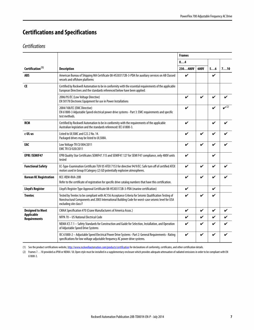
Certifications and Specifications
Certifications
Certification (1)
(1) See the product certifications website, http://www.rockwellautomation.com/products/certification for declarations of conformity, certificates, and other certification details.
Description
Frames
0…4
5…6 7…10230…480V 600V
ABS American Bureau of Shipping MA Certificate 08-HS303172B-3-PDA for auxiliary services on AB Classed vessels and offshore platforms
✔ ✔
CE Certified by Rockwell Automation to be in conformity with the essential requirements of the applicable European Directives and the standards referenced below have been applied:
2006/95/EC (Low Voltage Directive)EN 50178 Electronic Equipment for use in Power Installations
✔ ✔ ✔ ✔
2004/108/EC (EMC Directive)EN 61800-3 Adjustable Speed electrical power drive systems - Part 3: EMC requirements and specific test methods.
✔ ✔ ✔ (2)
(2) Frames 7…10 provided as IP00 or NEMA / UL Open style must be installed in a supplementary enclosure which provides adequate attenuation of radiated emissions in order to be compliant with EN 61800-3.
RCM Certified by Rockwell Automation to be in conformity with the requirements of the applicable Australian legislation and the standards referenced: IEC 61800-3.
✔ ✔ ✔
c-UL-us Listed to UL508C and C22.2 No. 14.Packaged drives may be listed to UL508A.
✔ ✔ ✔ ✔
EAC Low Voltage TR CU 004/2011EMC TR CU 020/2011
✔ ✔ ✔ ✔
EPRI /SEMIF47 EPRI Quality Star Certificates SEMIF47.115 and SEMIF47.127 for SEMI F47 compliance, only 480V units tested
✔ ✔
Functional Safety EC-Type-Examination Certificate TUV 05 ATEX 7153 for directive 94/9/EC: Safe turn off of certified ATEX motors used in Group II Category (2) GD potentially explosive atmospheres.
✔ ✔ ✔ ✔
Korean KC Registration KCC-REM-RAA-20BRefer to the certificate of registration for specific drive catalog numbers that have this certification.
✔ ✔ ✔ ✔
Lloyd’s Register Lloyd’s Register Type Approval Certificate 08-HS303172B-3-PDA (marine certification) ✔ ✔
Trentec Tested by Trentec to be compliant with AC156 Acceptance Criteria for Seismic Qualification Testing of Nonstructural Components and 2003 International Building Code for worst-case seismic level for USA excluding site class F
✔ ✔ ✔
Designed to Meet Applicable Requirements
CMAA Specification #70 (Crane Manufacturers of America Assoc.) ✔ ✔ ✔ ✔
NFPA 70 – US National Electrical Code ✔ ✔ ✔ ✔
NEMA ICS 7.1 – Safety Standards for Construction and Guide for Selection, Installation, and Operation of Adjustable Speed Drive Systems
✔ ✔ ✔ ✔
IEC 61800-2 – Adjustable Speed Electrical Power Drive Systems - Part 2: General Requirements - Rating specifications for low voltage adjustable frequency AC power drive systems.
✔ ✔ ✔ ✔

8 Rockwell Automation Publication 20B-TD001H-EN-P - July 2014
PowerFlex 700 Adjustable Frequency AC Drive
Environmental
Category Specification
Environment Altitude: 1000 m (3300 ft) max. without derating
Maximum Surrounding Air Temperature without Derating - IP20, NEMA / UL Type Open:
Frames 0…6Frames 7…10
0…50 °C (32…122 °F), typical. See Installation Instructions for details.0…40 °C (32…104 °F) for chassis (heatsink) 0…65 °C (32…149 °F) for control (front of backplane)
Storage Temperature (all const.): -40…70 °C (-40…158 °F)
Atmosphere: Important: Drive must not be installed in an area where the ambient atmosphere contains volatile or corrosive gas, vapors or dust. If the drive is not going to be installed for a period of time, it must be stored in an area where it will not be exposed to a corrosive atmosphere.
Relative Humidity: 5 to 95% non-condensing
Shock: 15G peak for 11ms duration (±1.0 ms)
Vibration: 0.152 mm (0.006 in.) displacement, 1G peak
Surrounding Environment Pollution DegreePollution Degree 1 & 2:Pollution Degree 3 & 4:
(See page 11 for descriptions of each pollution degree rating.)
All enclosures acceptable.Enclosure that meets or exceeds IP54, NEMA / UL Type 12 required.
Sound: Frame Fan Velocity Sound Level
Note: Sound pressure level is measured at 2 meters.
0 30 CFM 58 dB
1 30 CFM 59 dB
2 50 CFM 57 dB
3 120 CFM 61 dB
4 190 CFM 59 dB
5 200 CFM 71 dB
6 300 CFM 72 dB
7 756 CFM 74 dB
8 1200 CFM 78 dB
9 2800 CFM 82 dB
10 Inv. 1850 CFM 78 dB
10 Cnv. 1200 CFM 78 dB
Rockwell Automation Publication 20B-TD001H-EN-P - July 2014 9
PowerFlex 700 Adjustable Frequency AC Drive
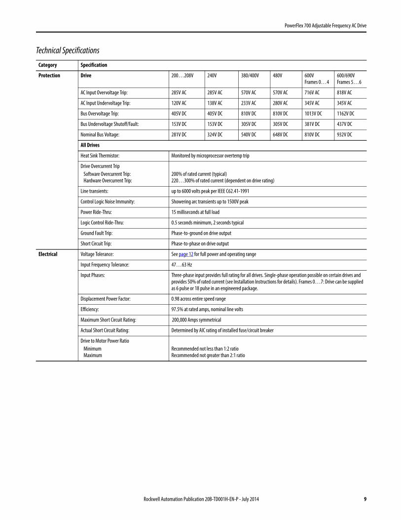
Technical Specifications
Category Specification
Protection Drive 200…208V 240V 380/400V 480V 600VFrames 0…4
600/690VFrames 5…6
AC Input Overvoltage Trip: 285V AC 285V AC 570V AC 570V AC 716V AC 818V AC
AC Input Undervoltage Trip: 120V AC 138V AC 233V AC 280V AC 345V AC 345V AC
Bus Overvoltage Trip: 405V DC 405V DC 810V DC 810V DC 1013V DC 1162V DC
Bus Undervoltage Shutoff/Fault: 153V DC 153V DC 305V DC 305V DC 381V DC 437V DC
Nominal Bus Voltage: 281V DC 324V DC 540V DC 648V DC 810V DC 932V DC
All Drives
Heat Sink Thermistor: Monitored by microprocessor overtemp trip
Drive Overcurrent TripSoftware Overcurrent Trip:Hardware Overcurrent Trip:
200% of rated current (typical)220…300% of rated current (dependent on drive rating)
Line transients: up to 6000 volts peak per IEEE C62.41-1991
Control Logic Noise Immunity: Showering arc transients up to 1500V peak
Power Ride-Thru: 15 milliseconds at full load
Logic Control Ride-Thru: 0.5 seconds minimum, 2 seconds typical
Ground Fault Trip: Phase-to-ground on drive output
Short Circuit Trip: Phase-to-phase on drive output
Electrical Voltage Tolerance: See page 12 for full power and operating range
Input Frequency Tolerance: 47…63 Hz
Input Phases: Three-phase input provides full rating for all drives. Single-phase operation possible on certain drives and provides 50% of rated current (see Installation Instructions for details). Frames 0…7: Drive can be supplied as 6 pulse or 18 pulse in an engineered package.
Displacement Power Factor: 0.98 across entire speed range
Efficiency: 97.5% at rated amps, nominal line volts
Maximum Short Circuit Rating: 200,000 Amps symmetrical
Actual Short Circuit Rating: Determined by AIC rating of installed fuse/circuit breaker
Drive to Motor Power RatioMinimumMaximum
Recommended not less than 1:2 ratioRecommended not greater than 2:1 ratio

10 Rockwell Automation Publication 20B-TD001H-EN-P - July 2014
PowerFlex 700 Adjustable Frequency AC Drive
Control Method: Sine coded PWM with programmable carrier frequency. Ratings apply to all drives (refer to the Derating Guidelines in the PowerFlex Reference Manual). The drive can be supplied as 6 pulse or 18 pulse in a configured package.
Carrier Frequency: 2, 4, 8, and 10 kHz. Drive rating based on 4 kHz. See the Input Protection Device tables in the Installation Instructions for exceptions.
Output Voltage Range: 0 to rated motor voltage
Output Frequency Range: Standard Control – 0 to 400 Hz., Vector Control – 0 to 420 Hz
Frequency AccuracyDigital Input:Analog Input:
Within ±0.01% of set output frequencyWithin ±0.4% of maximum output frequency
Frequency Control: Speed Regulation - w/Slip Compensation (Volts per Hertz Mode)0.5% of base speed across 40:1 speed range, 40:1 operating range10 rad/sec bandwidth
Speed Regulation - w/Slip Compensation (Sensorless Vector Mode)0.5% of base speed across 80:1 speed range, 80:1 operating range20 rad/sec bandwidth
Speed Regulation - w/Feedback (Sensorless Vector Mode)0.1% of base speed across 80:1 speed range, 80:1 operating range20 rad/sec bandwidth
Speed Control: Speed Regulation - w/o Feedback (Vector Control Mode)0.1% of base speed across 120:1 speed range, 120:1 operating range50 rad/sec bandwidth
Speed Regulation - w/Feedback (Vector Control Mode)0.001% of base speed across 120:1 speed range, 1000:1 operating range, 250 rad/sec bandwidth
Torque Regulation: Torque Regulation - w/o Feedback ±5%, 600 rad/sec bandwidth
Torque Regulation - w/Feedback ±2%, 2500 rad/sec bandwidth
Selectable Motor Control: Sensorless Vector with full tuning. Standard V/Hz with full custom capability. PF700 adds Vector Control.
Stop Modes: Multiple programmable stop modes including - Ramp, Coast, DC-Brake, Ramp-to-Hold and S-curve.
Accel/Decel: Two independently programmable accel and decel times. Each time may be programmed from 0…3600 seconds in 0.1 second increments.
Intermittent Overload: 110% Overload capability for up to 1 minute, 150% Overload capability for up to 3 seconds.
Current Limit Capability: Proactive Current Limit programmable from 20…160% of rated output current. Independently programmable proportional & integral gain.
Motor Overload ProtectionFrames 0…6 Standard Control:
Frames 0…6 Vector Control:
Frames 7…10 Vector Control:
PowerFlex 700 drives with standard control, identified by an N, A, or B in position 15 of the catalog number, only provide Class 10 motor overload protection according to NEC article 430. They do not provide speed sensitive overload protection, thermal memory retention and motor over-temperature sensing according to NEC article 430.126 (A) (2). If such protection is needed in the end-use product, it must be provided by additional means.PowerFlex 700 drives with vector control, identified by a C or D in position 15 of the catalog number, provide class 10 motor overload protection according to NEC article 430 and motor over-temperature protection according to NEC article 430.126 (A) (2). UL 508C File E59272.Class 10 motor overload protection according to NEC article 430 and motor over-temperature protection according to NEC article 430.126 (A)(2). UL 508C File E59272.
Category Specification

Rockwell Automation Publication 20B-TD001H-EN-P - July 2014 11
PowerFlex 700 Adjustable Frequency AC Drive
Pollution Degree Ratings According to EN 61800-5-1
Control(continued)
Digital/Analog Input Latency Signal Motor Control Latency
Min. Max Typical
Digital Input Start FVC 8.4 ms 10.4 ms 8.4 ms
SVC 9.2 ms 16.0 ms 9.2 ms
Stop FVC 10.0 ms 12.4 ms 10.4 ms
SVC 10.0 ms 12.0 ms 10.4 ms
Analog Input Torque 4 kHz PWM
FVC 772 µs 1.06 ms 840 µs
Torque 2 kHz PWM
FVC 1.008 ms 1.46 ms 1.256 ms
Speed FVC 4.6 ms 8.6 ms 4.8 ms
Speed SVC 4.8 ms 12.4 ms 6.4 ms
Encoder Type: Incremental, dual channel
Supply: 12V, 250 mA. 12V, 10 mA minimum inputs isolated with differential transmitter, 250 kHz maximum.
Quadrature: 90°, ±27 degrees at 25 degrees C.
Duty Cycle: 50%, +10%
Requirements: Encoders must be line driver type, quadrature (dual channel) or pulse (single channel), 8…15V DC output (4…6V DC when jumpers are in 5V position), single-ended or differential and capable of supplying a minimum of 10 mA per channel. Maximum input frequency is 250 kHz. The Encoder Interface Board accepts 12V DC square-wave with a minimum high state voltage of 7.0V DC. With the jumpers in the 5V position, the encoder will accept a 5V DC square-wave with a minimum high state voltage of 3.0V DC. In either jumper position, the maximum low state voltage is 0.4V DC.
Pollution Degree Description
1 No pollution or only dry, non-conductive pollution occurs. The pollution has no influence.
2 Normally, only non-conductive pollution occurs. Occasionally, however, a temporary conductivity caused by condensation is to be expected, when the drive is out of operation.
3 Conductive pollution or dry non-conductive pollution occurs, which becomes conductive due to condensation, which is to be expected.
4 The pollution generates persistent conductivity caused, for example, by conductive dust, rain or snow.
Category Specification

12 Rockwell Automation Publication 20B-TD001H-EN-P - July 2014
PowerFlex 700 Adjustable Frequency AC Drive
Design Considerations
Input Voltage Tolerance
Drive RatingNominal Line Voltage
Nominal Motor Voltage
Drive Full Power Range
Drive Operating Range
200…240 200 200 * 200…264 180…264
208 208 208…264
240 230 230…264
380…480 380 380 * 380…528 342…528
400 400 400…528
480 460 460…528
500…600(Frames 0…4 Only)
600 575 * 575…660 432…660
500…690(Frames 5 & 6 Only)
600 575 * 575…660 475…759
690 690 690…759 475…759
Drive Full Power Range = Nominal Motor Voltage to Drive Rated Voltage +10%.Rated current is available across the entire Drive Full Power Range
Drive Operating Range = Lowest* Nominal Motor Voltage –10% to Drive Rated Voltage +10%.Drive Output is linearly derated when Actual Line Voltage is less than the Nominal Motor Voltage
EXAMPLE Calculate the maximum power of a 5 Hp, 460V motor connected to a 480V rated drive supplied with 342V Actual Line Voltage input.
• Actual Line Voltage / Nominal Motor Voltage = 74.3%
• 74.3% × 5 Hp = 3.7 Hp
• 74.3% × 60 Hz = 44.6 HzAt 342V Actual Line Voltage, the maximum power the 5 Hp, 460V motor can produce is 3.7 Hp at 44.6 Hz.
HP
@ M
otor
(Dri
ve O
utp
ut)
Actual Line Voltage (Drive Input)
Full Power Range
Drive Operating Range
Nominal Motor Voltage -10%
Nominal Motor Voltage
Derated Power Range
Drive Rated Voltage
Drive Rated Voltage +10%
5 Hp
3.7 Hp
HP
@ M
otor
(Dri
ve O
utp
ut)
Actual Line Voltage (Drive Input)
342V460V
480V528V
22 Rockwell Automation Publication 20B-TD001H-EN-P - July 2014
PowerFlex 700 Adjustable Frequency AC Drive
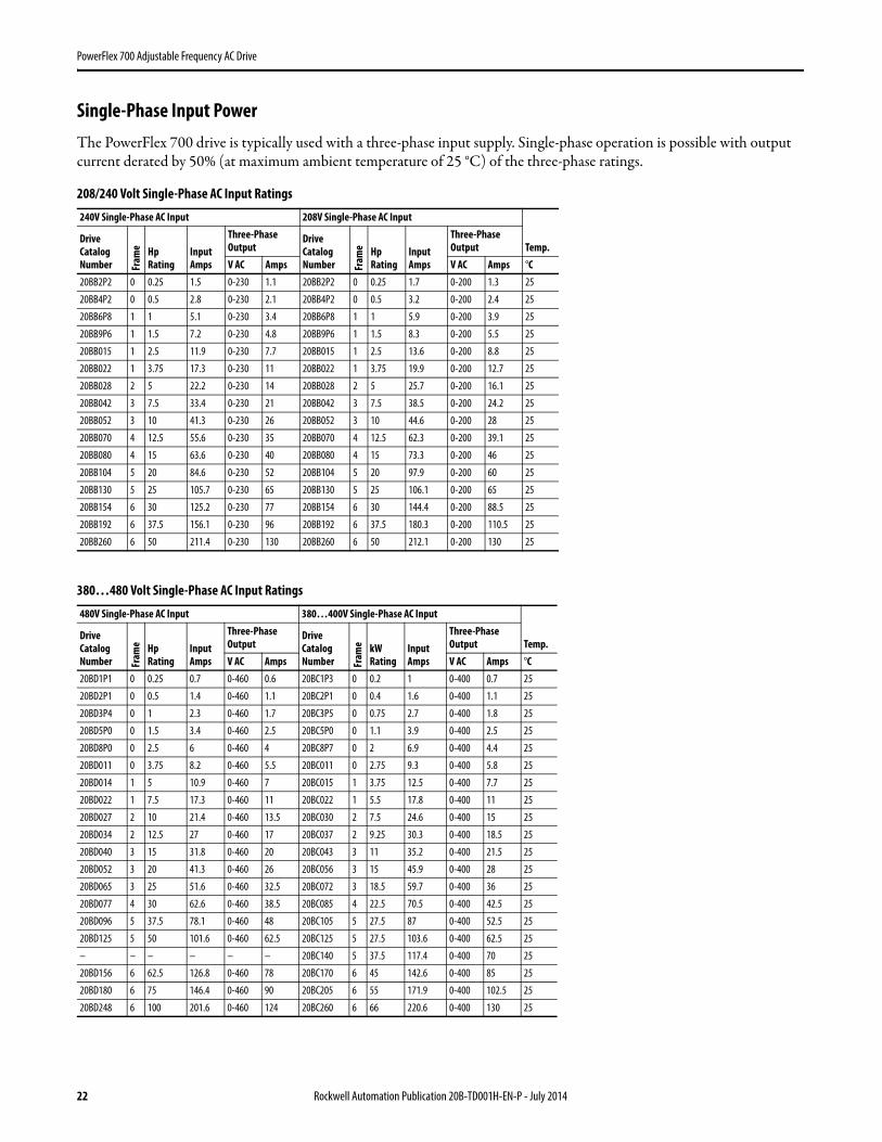
Single-Phase Input PowerThe PowerFlex 700 drive is typically used with a three-phase input supply. Single-phase operation is possible with output current derated by 50% (at maximum ambient temperature of 25 °C) of the three-phase ratings.
208/240 Volt Single-Phase AC Input Ratings
380…480 Volt Single-Phase AC Input Ratings
240V Single-Phase AC Input 208V Single-Phase AC Input
Temp.Drive Catalog Number Fr
ame Hp
RatingInput Amps
Three-Phase Output
Drive Catalog Number Fr
ame Hp
RatingInput Amps
Three-Phase Output
V AC Amps V AC Amps °C20BB2P2 0 0.25 1.5 0-230 1.1 20BB2P2 0 0.25 1.7 0-200 1.3 25
20BB4P2 0 0.5 2.8 0-230 2.1 20BB4P2 0 0.5 3.2 0-200 2.4 25
20BB6P8 1 1 5.1 0-230 3.4 20BB6P8 1 1 5.9 0-200 3.9 25
20BB9P6 1 1.5 7.2 0-230 4.8 20BB9P6 1 1.5 8.3 0-200 5.5 25
20BB015 1 2.5 11.9 0-230 7.7 20BB015 1 2.5 13.6 0-200 8.8 25
20BB022 1 3.75 17.3 0-230 11 20BB022 1 3.75 19.9 0-200 12.7 25
20BB028 2 5 22.2 0-230 14 20BB028 2 5 25.7 0-200 16.1 25
20BB042 3 7.5 33.4 0-230 21 20BB042 3 7.5 38.5 0-200 24.2 25
20BB052 3 10 41.3 0-230 26 20BB052 3 10 44.6 0-200 28 25
20BB070 4 12.5 55.6 0-230 35 20BB070 4 12.5 62.3 0-200 39.1 25
20BB080 4 15 63.6 0-230 40 20BB080 4 15 73.3 0-200 46 25
20BB104 5 20 84.6 0-230 52 20BB104 5 20 97.9 0-200 60 25
20BB130 5 25 105.7 0-230 65 20BB130 5 25 106.1 0-200 65 25
20BB154 6 30 125.2 0-230 77 20BB154 6 30 144.4 0-200 88.5 25
20BB192 6 37.5 156.1 0-230 96 20BB192 6 37.5 180.3 0-200 110.5 25
20BB260 6 50 211.4 0-230 130 20BB260 6 50 212.1 0-200 130 25
480V Single-Phase AC Input 380…400V Single-Phase AC Input
Temp.Drive Catalog Number Fr
ame Hp
RatingInput Amps
Three-Phase Output
Drive Catalog Number Fr
ame kW
RatingInput Amps
Three-Phase Output
V AC Amps V AC Amps °C20BD1P1 0 0.25 0.7 0-460 0.6 20BC1P3 0 0.2 1 0-400 0.7 25
20BD2P1 0 0.5 1.4 0-460 1.1 20BC2P1 0 0.4 1.6 0-400 1.1 25
20BD3P4 0 1 2.3 0-460 1.7 20BC3P5 0 0.75 2.7 0-400 1.8 25
20BD5P0 0 1.5 3.4 0-460 2.5 20BC5P0 0 1.1 3.9 0-400 2.5 25
20BD8P0 0 2.5 6 0-460 4 20BC8P7 0 2 6.9 0-400 4.4 25
20BD011 0 3.75 8.2 0-460 5.5 20BC011 0 2.75 9.3 0-400 5.8 25
20BD014 1 5 10.9 0-460 7 20BC015 1 3.75 12.5 0-400 7.7 25
20BD022 1 7.5 17.3 0-460 11 20BC022 1 5.5 17.8 0-400 11 25
20BD027 2 10 21.4 0-460 13.5 20BC030 2 7.5 24.6 0-400 15 25
20BD034 2 12.5 27 0-460 17 20BC037 2 9.25 30.3 0-400 18.5 25
20BD040 3 15 31.8 0-460 20 20BC043 3 11 35.2 0-400 21.5 25
20BD052 3 20 41.3 0-460 26 20BC056 3 15 45.9 0-400 28 25
20BD065 3 25 51.6 0-460 32.5 20BC072 3 18.5 59.7 0-400 36 25
20BD077 4 30 62.6 0-460 38.5 20BC085 4 22.5 70.5 0-400 42.5 25
20BD096 5 37.5 78.1 0-460 48 20BC105 5 27.5 87 0-400 52.5 25
20BD125 5 50 101.6 0-460 62.5 20BC125 5 27.5 103.6 0-400 62.5 25
– – – – – – 20BC140 5 37.5 117.4 0-400 70 25
20BD156 6 62.5 126.8 0-460 78 20BC170 6 45 142.6 0-400 85 25
20BD180 6 75 146.4 0-460 90 20BC205 6 55 171.9 0-400 102.5 25
20BD248 6 100 201.6 0-460 124 20BC260 6 66 220.6 0-400 130 25
Rockwell Automation Publication 20B-TD001H-EN-P - July 2014 23
PowerFlex 700 Adjustable Frequency AC Drive
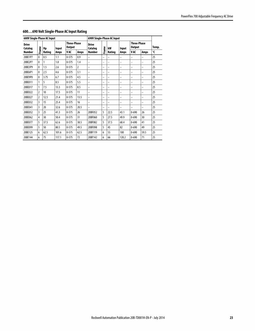
600…690 Volt Single-Phase AC Input Rating
600V Single-Phase AC Input 690V Single-Phase AC Input
Temp.Drive Catalog Number Fr
ame Hp
RatingInput Amps
Three-Phase Output
Drive Catalog Number Fr
ame kW
RatingInput Amps
Three-Phase Output
V AC Amps V AC Amps °C20BE1P7 0 0.5 1.1 0-575 0.9 – – – – – – 25
20BE2P7 0 1 1.8 0-575 1.4 – – – – – – 25
20BE3P9 0 1.5 2.6 0-575 2 – – – – – – 25
20BE6P1 0 2.5 4.6 0-575 3.1 – – – – – – 25
20BE9P0 0 3.75 6.7 0-575 4.5 – – – – – – 25
20BE011 1 5 8.5 0-575 5.5 – – – – – – 25
20BE017 1 7.5 13.3 0-575 8.5 – – – – – – 25
20BE022 2 10 17.5 0-575 11 – – – – – – 25
20BE027 2 12.5 21.4 0-575 13.5 – – – – – – 25
20BE032 3 15 25.4 0-575 16 – – – – – – 25
20BE041 3 20 32.6 0-575 20.5 – – – – – – 25
20BE052 3 25 41.3 0-575 26 20BF052 5 22.5 43.1 0-690 26 25
20BE062 4 30 50.4 0-575 31 20BF060 5 27.5 49.9 0-690 30 25
20BE077 5 37.5 62.6 0-575 38.5 20BF082 5 37.5 68.4 0-690 41 25
20BE099 5 50 80.5 0-575 49.5 20BF098 5 45 82 0-690 49 25
20BE125 6 62.5 101.6 0-575 62.5 20BF119 6 55 100 0-690 59.5 25
20BE144 6 75 117.1 0-575 72 20BF142 6 66 120.2 0-690 71 25

24 Rockwell Automation Publication 20B-TD001H-EN-P - July 2014
PowerFlex 700 Adjustable Frequency AC Drive
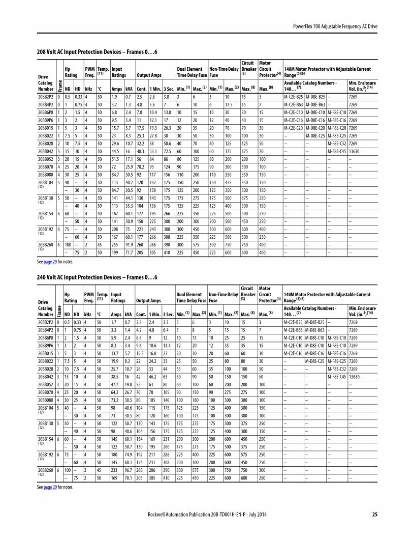
Drive, Fuse and Circuit Breaker RatingsThe PowerFlex 700 can be installed with input fuses or an input circuit breaker. National and local industrial safety regulations and/or electrical codes can determine additional requirements for these installations.
The tables on the following pages provide recommended AC line input fuse and circuit breaker information. See Fusing and Circuit Breakers below for UL and IEC requirements. Sizes listed are the recommended sizes based on 40 °C (104 °F) and the U.S. NEC. Other country, state, or local codes can require different ratings. Tables with DC link fuse recommendations for DC input drives are also provided.
Fusing
The recommended fuse types are listed below. If available current ratings do not match those listed in the tables provided, choose the next higher fuse rating.
• IEC – BS88 (British Standard) Parts 1 & 2, EN60269-1, Parts 1 & 2(1), type gG or equivalent must be used.• UL – UL Class CC, T, RK1 or J must be used for Frames 0…6.
UL Class T, RK1, J, or L must be used for Frames 7…10.
Circuit Breakers
The “non-fuse” listings in the following tables include inverse time circuit breakers, instantaneous trip circuit breakers (motor circuit protectors) and 140M self-protected combination motor controllers (Frames 0…6 only). If one of these is chosen as the desired protection method, the following requirements apply:
• IEC – Both types of circuit breakers and 140M self-protected combination motor controllers (Frames 0…6 only) are acceptable for IEC installations.
• UL – Only inverse time circuit breakers and the specified 140M self-protected combination motor controllers (Frames 0…6 only) are acceptable for UL installations.
(1) Typical designations include, but may not be limited to the following; Parts 1 & 2: AC, AD, BC, BD, CD, DD, ED, EFS, EF, FF, FG, GF, GG, GH.
Rockwell Automation Publication 20B-TD001H-EN-P - July 2014 25
PowerFlex 700 Adjustable Frequency AC Drive
208 Volt AC Input Protection Devices – Frames 0…6
240 Volt AC Input Protection Devices – Frames 0…6
Drive Catalog Number Fr
ame
Hp Rating
PWM Freq.
Temp.(11)
Input Ratings Output Amps
Dual Element Time Delay Fuse
Non-Time Delay Fuse
Circuit Breaker(3)
Motor Circuit Protector(4)
140M Motor Protector with Adjustable Current Range (5)(6)
ND HD kHz °C Amps kVA Cont. 1 Min. 3 Sec. Min. (1) Max. (2) Min. (1) Max. (2) Max. (8) Max. (8)Available Catalog Numbers - 140… (7)
Min. Enclosure Vol. (in.3) (14)
20BB2P2 0 0.5 0.33 4 50 1.9 0.7 2.5 2.8 3.8 3 6 3 10 15 3 M-C2E-B25 M-D8E-B25 – 726920BB4P2 0 1 0.75 4 50 3.7 1.3 4.8 5.6 7 6 10 6 17.5 15 7 M-C2E-B63 M-D8E-B63 – 726920BB6P8 1 2 1.5 4 50 6.8 2.4 7.8 10.4 13.8 10 15 10 30 30 15 M-C2E-C10 M-D8E-C10 M-F8E-C10 726920BB9P6 1 3 2 4 50 9.5 3.4 11 12.1 17 12 20 12 40 40 15 M-C2E-C16 M-D8E-C16 M-F8E-C16 726920BB015 1 5 3 4 50 15.7 5.7 17.5 19.3 26.3 20 35 20 70 70 30 M-C2E-C20 M-D8E-C20 M-F8E-C20 726920BB022 1 7.5 5 4 50 23 8.3 25.3 27.8 38 30 50 30 100 100 30 – M-D8E-C25 M-F8E-C25 726920BB028 2 10 7.5 4 50 29.6 10.7 32.2 38 50.6 40 70 40 125 125 50 – – M-F8E-C32 726920BB042 3 15 10 4 50 44.5 16 48.3 53.1 72.5 60 100 60 175 175 70 – – M-F8E-C45 1363020BB052 3 20 15 4 50 51.5 17.1 56 64 86 80 125 80 200 200 100 – – – –20BB070 4 25 20 4 50 72 25.9 78.2 93 124 90 175 90 300 300 100 – – – –20BB080 4 30 25 4 50 84.7 30.5 92 117 156 110 200 110 350 350 150 – – – –20BB104(12)
5 40 – 4 50 113 40.7 120 132 175 150 250 150 475 350 150 – – – –– 30 4 50 84.7 30.5 92 138 175 125 200 125 350 300 150 – – – –
20BB130(12)
5 50 – 4 50 141 44.1 130 143 175 175 275 175 500 375 250 – – – –– 40 4 50 113 35.3 104 156 175 125 225 125 400 300 150 – – – –
20BB154(12)
6 60 – 4 50 167 60.1 177 195 266 225 350 225 500 500 250 – – – –– 50 4 50 141 50.9 150 225 300 200 300 200 500 450 250 – – – –
20BB192(12)
6 75 – 4 50 208 75 221 243 308 300 450 300 600 600 400 – – – –– 60 4 50 167 60.1 177 266 308 225 350 225 500 500 250 – – – –
20BB260(12)
6 100 – 2 45 255 91.9 260 286 390 300 575 300 750 750 400 – – – –– 75 2 50 199 71.7 205 305 410 225 450 225 600 600 400 – – – –
See page 29 for notes.
Drive Catalog Number Fr
ame
Hp Rating
PWM Freq.
Temp.(11)
Input Ratings Output Amps
Dual Element Time Delay Fuse
Non-Time Delay Fuse
Circuit Breaker(3)
Motor Circuit Protector(4)
140M Motor Protector with Adjustable Current Range (5)(6)
ND HD kHz °C Amps kVA Cont. 1 Min. 3 Sec. Min. (1) Max. (2) Min. (1) Max. (2) Max. (8) Max. (8)Available Catalog Numbers - 140… (7)
Min. Enclosure Vol. (in.3)(14)
20BB2P2 0 0.5 0.33 4 50 1.7 0.7 2.2 2.4 3.3 3 6 3 10 15 3 M-C2E-B25 M-D8E-B25 – 726920BB4P2 0 1 0.75 4 50 3.3 1.4 4.2 4.8 6.4 5 8 5 15 15 7 M-C2E-B63 M-D8E-B63 – 726920BB6P8 1 2 1.5 4 50 5.9 2.4 6.8 9 12 10 15 10 25 25 15 M-C2E-C10 M-D8E-C10 M-F8E-C10 726920BB9P6 1 3 2 4 50 8.3 3.4 9.6 10.6 14.4 12 20 12 35 35 15 M-C2E-C10 M-D8E-C10 M-F8E-C10 726920BB015 1 5 3 4 50 13.7 5.7 15.3 16.8 23 20 30 20 60 60 30 M-C2E-C16 M-D8E-C16 M-F8E-C16 726920BB022 1 7.5 5 4 50 19.9 8.3 22 24.2 33 25 50 25 80 80 30 – M-D8E-C25 M-F8E-C25 726920BB028 2 10 7.5 4 50 25.7 10.7 28 33 44 35 60 35 100 100 50 – – M-F8E-C32 726920BB042 3 15 10 4 50 38.5 16 42 46.2 63 50 90 50 150 150 50 – – M-F8E-C45 1363020BB052 3 20 15 4 50 47.7 19.8 52 63 80 60 100 60 200 200 100 – – – –20BB070 4 25 20 4 50 64.2 26.7 70 78 105 90 150 90 275 275 100 – – – –20BB080 4 30 25 4 50 73.2 30.5 80 105 140 100 180 100 300 300 100 – – – –20BB104(12)
5 40 – 4 50 98 40.6 104 115 175 125 225 125 400 300 150 – – – –– 30 4 50 73 30.5 80 120 160 100 175 100 300 300 100 – – – –
20BB130(12)
5 50 – 4 50 122 50.7 130 143 175 175 275 175 500 375 250 – – – –– 40 4 50 98 40.6 104 156 175 125 225 125 400 300 150 – – – –
20BB154(12)
6 60 – 4 50 145 60.1 154 169 231 200 300 200 600 450 250 – – – –– 50 4 50 122 50.7 130 195 260 175 275 175 500 375 250 – – – –
20BB192(12)
6 75 – 4 50 180 74.9 192 211 288 225 400 225 600 575 250 – – – –– 60 4 50 145 60.1 154 231 308 200 300 200 600 450 250 – – – –
20BB260(12)
6 100 – 2 45 233 96.7 260 286 390 300 575 300 750 750 300 – – – –– 75 2 50 169 70.1 205 305 410 225 450 225 600 600 250 – – – –
See page 29 for notes.

26 Rockwell Automation Publication 20B-TD001H-EN-P - July 2014
PowerFlex 700 Adjustable Frequency AC Drive
400 Volt AC Input Protection Devices – Frames 0…6
400 Volt AC Input Protection Devices – Frames 7…10
Drive Catalog Number Fr
ame
kW Rating
PWM Freq. Temp.
Input Ratings Output Amps
Dual Element Time Delay Fuse
Non-Time Delay Fuse
Circuit Breaker(3)
Motor Circuit Protector(4)
140M Motor Protector with Adjustable Current Range(5)(6)
ND HD kHz °C Amps kVA Cont. 1 Min. 3 Sec. Min. (1) Max. (2) Min. (1) Max. (2) Max. (8) Max. (8)Available Catalog Numbers - 140… (7)
Min. Enclosure Vol. (in.3) (14)
20BC1P3 0 0.37 0.25 4 50 (11) 1.1 0.77 1.3 1.4 1.9 3 3 3 6 15 3 M-C2E-B16 – – 726920BC2P1 0 0.75 0.55 4 50 (11) 1.8 1.3 2.1 2.4 3.2 3 6 3 8 15 3 M-C2E-B25 M-D8E-B25 – 726920BC3P5 0 1.5 0.75 4 50 (11) 3.2 2.2 3.5 4.5 6 6 7 6 12 15 7 M-C2E-B40 M-D8E-B40 – 726920BC5P0 0 2.2 1.5 4 50 (11) 4.6 3.2 5 5.5 7.5 6 10 6 20 20 7 M-C2E-B63 M-D8E-B63 – 726920BC8P7 0 4 2.2 4 50 (11) 7.9 5.5 8.7 9.9 13.2 15 17.5 15 30 30 15 M-C2E-C10 M-D8E-C10 M-F8E-C10 726920BC011 0 5.5 4 4 50 (11) 10.8 7.5 11.5 13 17.4 15 25 15 45 45 15 M-C2E-C16 M-D8E-C16 M-F8E-C16 726920BC015 1 7.5 5.5 4 50 (11) 14.4 10 15.4 17.2 23.1 20 30 20 60 60 20 M-C2E-C20 M-D8E-C20 M-F8E-C20 726920BC022 1 11 7.5 4 50 (11) 20.6 14.3 22 24.2 33 30 45 30 80 80 30 – M-D8E-C25 M-F8E-C25 726920BC030 2 15 11 4 50 (11) 28.4 19.7 30 33 45 35 60 35 120 120 50 – – M-F8E-C32 726920BC037 2 18.5 15 4 50 (11) 35 24.3 37 45 60 45 80 45 125 125 50 – – M-F8E-C45 726920BC043 3 22 18.5 4 50 (11) 40.7 28.2 43 56 74 60 90 60 150 150 60 – – – –20BC056 3 30 22 4 50 (11) 53 36.7 56 64 86 70 125 70 200 200 100 – – – –20BC072 3 37 30 4 50 (10)(11) 68.9 47.8 72 84 112 90 150 90 250 250 100 – – – –20BC085(12)
4 45 – 4 45 (11) 81.4 56.4 85 94 128 110 200 110 300 300 150 – – – –– 37 4 45 (11) 68.9 47.8 72 108 144 90 175 90 275 300 100 – – – –
20BC105(12)
5 55 – 4 50 (9) 100.5 69.6 105 116 158 125 225 125 400 300 150 – – – –– 45 4 50 (9) 81.4 56.4 85 128 170 110 175 110 300 300 150 – – – –
20BC125(12)
5 55 – 4 50 (9) 121.1 83.9 125 138 163 150 275 150 500 375 250 – – – –– 45 4 50 (9) 91.9 63.7 96 144 168 125 200 125 375 375 150 – – – –
20BC140(12)
5 75 – 4 40 (9) 136 93.9 140 154 190 200 300 200 400 400 250 – – – –– 55 4 40 (9) 101 69.6 105 157 190 150 225 150 300 300 150 – – – –
20BC170(12)
6 90 – 4 50 (9) 164 126 170 187 255 250 375 250 600 500 250 – – – –– 75 4 50 (9) 136 103 140 210 280 200 300 200 550 400 250 – – – –
20BC205(12)
6 110 – 4 40 (9) 199 148 205 220 289 250 450 250 600 600 400 – – – –– 90 4 40 (9) 164 126 170 255 313 250 375 250 600 500 250 – – – –
20BC260(12)
6 132 – 2 45 (9) 255 177 260 286 390 350 550 350 750 750 400 – – – –– 110 2 50 (9) 199 138 205 308 410 250 450 250 600 600 400 – – – –
See page 29 for notes.
Drive Catalog Number (12)
Fram
e kW Rating PWM Freq. Temp. (16) Input Ratings Output AmpsDual Element Time Delay Fuse
Non-Time Delay Fuse
Circuit Breaker (3)
Motor Circuit Protector (4)
ND HD kHz °C Amps kVA Cont. 1 Min. 3 Sec. Min. (1) Max. (2) Min. (1) Max. (2) Max. (8) Max. (8)
20BC292 7 160 4 40 293 203 292 322 438 375 650 375 850 850 400150 4 40 264 183 263 395 526 350 550 350 550 750 400
20BC325 7 180 4 40 326 226 325 358 488 425 700 425 950 950 600180 4 40 326 226 325 488 650 425 700 425 950 950 600
20BC365 8 200 2 40 366 253 365 402 548 475 800 475 1000 1000 600180 2 40 326 226 325 488 650 425 700 425 950 950 600
20BC415 8 240 2 40 416 288 415 457 623 525 900 525 1200 1200 600200 2 40 366 253 365 548 730 475 800 475 1000 1000 600
20BC481 8 280 2 40 483 334 481 530 722 600 1000 600 1400 1400 700240 2 40 416 288 415 623 830 525 900 525 1200 1200 600
20BC535 8 300 2 40 537 372 535 589 803 700 1200 700 1600 1600 700280 2 40 483 334 481 722 962 600 1000 600 1400 1400 700
20BC600 8 350 2 40 602 417 600 660 900 750 1300 750 1800 1800 800300 2 40 537 371 535 803 1070 700 1200 700 1600 1600 700
20BC730 9 400 2 40 702 486 730 803 1095 900 1500 900 2100 2100 900350 2 40 602 417 600 900 1200 750 1300 750 1800 1800 800
20BC875 10 500 2 40 877 608 875 963 1313 1100 1900 1100 2600 2600 1200400 2 40 877 486 700 1050 1400 900 1500 900 2100 2100 900
See page 29 for notes.

Rockwell Automation Publication 20B-TD001H-EN-P - July 2014 27
PowerFlex 700 Adjustable Frequency AC Drive
480 Volt AC Input Protection Devices – Frames 0…6
480 Volt AC Input Protection Devices – Frames 7…10
Drive Catalog Number Fr
ame
Hp Rating
PWM Freq. Temp.
Input Ratings Output Amps
Dual Element Time Delay Fuse
Non-Time Delay Fuse
Circuit Breaker(3)
Motor Circuit Protector(4)
140M Motor Protector with Adjustable Current Range (5)(6)
ND HD kHz °C Amps kVA Cont. 1 Min. 3 Sec. Min. (1) Max. (2) Min. (1) Max. (2) Max. (8) Max. (8)Available Catalog Numbers - 140… (7)
Min. Enclosure Vol. (in.3) (14)
20BD1P1 0 0.5 0.33 4 50 (11) 0.9 0.7 1.1 1.2 1.6 3 3 3 6 15 3 M-C2E-B16 – – 726920BD2P1 0 1 0.75 4 50 (11) 1.6 1.4 2.1 2.4 3.2 3 6 3 8 15 3 M-C2E-B25 – – 726920BD3P4 0 2 1.5 4 50 (11) 2.6 2.2 3.4 4.5 6 4 8 4 12 15 7 M-C2E-B40 M-D8E-B40 – 726920BD5P0 0 3 2 4 50 (11) 3.9 3.2 5 5.5 7.5 6 10 6 20 20 7 M-C2E-B63 M-D8E-B63 – 726920BD8P0 0 5 3 4 50 (11) 6.9 5.7 8 8.8 12 10 15 10 30 30 15 M-C2E-C10 M-D8E-C10 M-F8E-C10 726920BD011 0 7.5 5 4 50 (11) 9.5 7.9 11 12.1 16.5 15 20 15 40 40 15 M-C2E-C16 M-D8E-C16 M-F8E-C16 726920BD014 1 10 7.5 4 50 (11) 12.5 10.4 14 16.5 22 17.5 30 17.5 50 50 20 M-C2E-C16 M-D8E-C16 M-F8E-C16 726920BD022 1 15 10 4 50 (11) 19.9 16.6 22 24.2 33 25 50 25 80 80 30 – M-D8E-C25 M-F8E-C25 726920BD027 2 20 15 4 50 (11) 24.8 20.6 27 33 44 35 60 35 100 100 50 – – M-F8E-C32 726920BD034 2 25 20 4 50 (11) 31.2 25.9 34 40.5 54 40 70 40 125 125 50 – – M-F8E-C45 726920BD040 3 30 25 4 50 (11) 36.7 30.5 40 51 68 50 90 50 150 150 50 – – M-F8E-C45 1363020BD052 3 40 30 4 50 (11) 47.7 39.7 52 60 80 60 110 60 200 200 70 – – – –20BD065 3 50 40 4 50 (11) 59.6 49.6 65 78 104 80 125 80 250 250 100 – – – –20BD077(12)
4 60 – 4 50 (11) 72.3 60.1 77 85 116 100 170 100 300 300 100 – – – –– 50 4 50 (11) 59.6 49.6 65 98 130 80 125 80 250 250 100 – – – –
20BD096(12)
5 75 – 4 50 (9) 90.1 74.9 96 106 144 125 200 125 350 350 125 – – – –– 60 4 50 (9) 72.3 60.1 77 116 154 100 170 100 300 300 100 – – – –
20BD125(12)
5 100 – 4 50 (9) 117 97.6 125 138 163 150 250 150 500 375 150 – – – –– 75 4 50 (9) 90.1 74.9 96 144 168 125 200 125 350 350 125 – – – –
20BD156(12)
6 125 – 4 50 (9) 147 122 156 172 234 200 350 200 600 450 250 – – – –– 100 4 50 (9) 131 109 125 188 250 175 250 175 500 375 250 – – – –
20BD180(12)
6 150 – 4 50 (9) 169 141 180 198 270 225 400 225 600 500 250 – – – –– 125 4 50 (9) 147 122 156 234 312 200 350 200 600 450 250 – – – –
20BD248(12)
6 200 – 2 45 (9) 233 194 248 273 372 300 550 300 700 700 400 – – – –– 150 2 50 (9) 169
(17)141 180 270 360 225 400 225 600 500 250 – – – –
See page 29 for notes.
Drive Catalog Number (12)
Fram
e Hp Rating PWM Freq. Temp. (16) Input Ratings Output AmpsDual Element Time Delay Fuse
Non-Time Delay Fuse
Circuit Breaker (3)
Motor Circuit Protector (4)
ND HD kHz °C Amps kVA Cont. 1 Min. 3 Sec. Min. (1) Max. (2) Min. (1) Max. (2) Max. (8) Max. (8)
20BD292 7 250 4 40 281 233 292 322 438 375 650 375 850 850 400200 4 40 253 210 263 395 526 350 550 350 550 750 400
20BD325 7 250 4 40 313 260 325 358 488 425 700 425 950 950 600250 4 40 313 260 325 488 650 425 700 425 950 950 600
20BD365 8 300 2 40 351 292 365 402 548 475 800 475 1000 1000 600250 2 40 313 260 325 488 650 425 700 425 950 950 600
20BD415 8 350 2 40 399 331 415 457 623 525 900 525 1200 1200 600300 2 40 351 291 365 548 730 475 800 475 1000 1000 600
20BD481 8 400 2 40 462 384 481 530 722 600 1000 600 1400 1400 700350 2 40 399 331 415 623 830 525 900 525 1200 1200 600
20BD535 8 450 2 40 514 427 535 589 803 700 1200 700 1600 1600 700400 2 40 462 384 481 722 962 600 1000 600 1400 1400 700
20BD600 8 500 2 40 577 479 600 660 900 750 1300 750 1800 1800 800450 2 40 514 427 535 803 1070 700 1200 700 1600 1600 700
20BD730 9 600 2 40 673 559 730 803 1095 900 1500 900 2100 2100 900500 2 40 577 479 600 900 1200 750 1300 750 1800 1800 800
20BD875 10 700 2 40 841 699 875 963 1313 1100 1900 1100 2600 2600 1200600 2 40 673 559 700 1050 1400 900 1500 900 2100 2100 900
See page 29 for notes.

28 Rockwell Automation Publication 20B-TD001H-EN-P - July 2014
PowerFlex 700 Adjustable Frequency AC Drive
600 Volt AC Input Protection Devices – Frames 0…6 (13)
690 Volt AC Input Protection Devices – Frames 0…6 (13)
Drive Catalog Number Fr
ame
Hp Rating
PWM Freq.
Temp.(11)
Input Ratings Output Amps
Dual Element Time Delay Fuse
Non-Time Delay Fuse
Circuit Breaker(3)
Motor Circuit Protector (4)
140M Motor Protector with Adjustable Current Range (5)(6)
ND HD kHz °C Amps kVA Cont. 1 Min. 3 Sec. Min. (1) Max. (2) Min. (1) Max. (2) Max. (8) Max. (8)Available Catalog Numbers - 140… (7)
Min. Enclosure Vol. (in.3) (14)
20BE1P7 0 1 0.5 4 50 1.3 1.4 1.7 2 2.6 2 4 2 6 15 3 M-C2E-B16 – – 726920BE2P7 0 2 1 4 50 2.1 2.1 2.7 3.6 4.8 3 6 3 10 15 3 M-C2E-B25 – – 726920BE3P9 0 3 2 4 50 3 3.1 3.9 4.3 5.9 6 9 6 15 15 7 M-C2E-B40 M-D8E-B40 – 726920BE6P1 0 5 3 4 50 5.3 5.5 6.1 6.7 9.2 9 12 9 20 20 15 – M-D8E-B63 – 726920BE9P0 0 7.5 5 4 50 7.8 8.1 9 9.9 13.5 10 20 10 35 30 15 – M-D8E-C10 M-F8E-C10 726920BE011 1 10 7.5 4 50 9.9 10.2 11 13.5 18 15 25 15 40 40 15 – M-D8E-C10 M-F8E-C10 726920BE017 1 15 10 4 50 15.4 16 17 18.7 25.5 20 40 20 60 50 20 – M-D8E-C16 M-F8E-C16 726920BE022 2 20 15 4 50 20.2 21 22 25.5 34 30 50 30 80 80 30 – – M-F8E-C25 726920BE027 2 25 20 4 50 24.8 25.7 27 33 44 35 60 35 100 100 50 – – M-F8E-C25 726920BE032 3 30 25 4 50 29.4 30.5 32 40.5 54 40 70 40 125 125 50 – – M-F8E-C32 1363020BE041 3 40 30 4 50 37.6 39.1 41 48 64 50 90 50 150 150 100 – – – –20BE052 3 50 40 4 50 47.7 49.6 52 61.5 82 60 110 60 200 200 100 – – – –20BE062 4 60 50 2 50 58.2 60.5 62 78 104 80 125 80 225 225 100 – – – –20BE077 (12)
5 75 – 2 50 (9) 72.3 75.1 77 85 116 90 150 90 300 300 100 – – – –– 60 2 50 (9) 58.2 60.5 63 94 126 90 125 90 250 250 100 – – – –
20BE099 (12)
5 100 – 2 40 (9) 92.9 96.6 99 109 126 125 200 125 375 375 150 – – – –– 75 2 40 (9) 72.3 75.1 77 116 138 100 175 100 300 300 100 – – – –
20BE125 (12)
6 125 – 2 50 (9) 117 122 125 138 188 150 250 150 375 375 250 – – – –– 100 2 50 (9) 93 96.6 99 149 198 125 200 125 375 375 150 – – – –
20BE144 (12)
6 150 – 2 50 (9) 135 141 144 158 216 175 300 175 400 400 250 – – – –– 125 2 50 (9) 117 122 125 188 250 150 275 150 375 375 250 – – – –
See page 29 for notes.
Drive Catalog Number (12)
Fram
e
kW Rating
PWM Freq. Temp.(11) Input Ratings Output Amps
Dual Element Time Delay Fuse
Non-Time Delay Fuse
Circuit Breaker (3)
Motor Circuit Protector (4)
ND HD kHz °C Amps kVA Cont. 1 Min. 3 Sec. Min. (1) Max. (2) Min. (1) Max. (2) Max. (8) Max. (8)
20BF052 5 45 – 4 50 (9) 46.9 56.1 52 57 78 60 110 60 175 175 –– 37.5 4 50 (9) 40.1 48 46 69 92 50 90 50 150 150 –
20BF060 5 55 – 4 50 (9) 57.7 68.9 60 66 90 80 125 80 225 225 –– 45 4 50 (9) 46.9 56.1 52 78 104 60 110 60 175 175 –
20BF082 5 75 – 2 50 (9) 79 94.4 82 90 123 100 200 100 375 375 –– 55 2 50 (9) 57.7 68.9 60 90 120 80 125 80 225 225 –
20BF098 5 90 – 2 40 (9) 94.7 113 98 108 127 125 200 125 375 375 –– 75 2 40 (9) 79 94.4 82 123 140 100 200 100 375 375 –
20BF119 6 110 – 2 50 (9) 115 137 119 131 179 150 250 150 400 – –– 90 2 50 (9) 94.7 113 98 147 196 125 200 125 375 – –
20BF142 6 132 – 2 50 (9) 138 165 142 156 213 175 300 175 450 – –– 110 2 50 (9) 115 137 119 179 238 150 250 150 400 – –
See page 29 for notes.
Rockwell Automation Publication 20B-TD001H-EN-P - July 2014 29
PowerFlex 700 Adjustable Frequency AC Drive
Notes(1) Minimum protection device size is the lowest rated device that supplies maximum protection without nuisance tripping.(2) Maximum protection device size is the highest rated device that supplies drive protection. For US NEC, minimum size is 125% of motor FLA. Ratings shown are maximum.(3) Circuit Breaker - inverse time breaker. For US NEC, minimum size is 125% of motor FLA. Ratings shown are maximum.(4) Motor Circuit Protector - instantaneous trip circuit breaker. For US NEC minimum size is 125% of motor FLA. Ratings shown are maximum.(5) Bulletin 140M with adjustable current range must have the current trip set to the minimum range that the device will not trip.(6) Manual Self-Protected (Type E) Combination Motor Controller, UL listed for 208 Wye or Delta, 240 Wye or Delta, 480Y/277 or 600Y/ 347. Not UL listed for use on 480V or 600V Delta/Delta, corner ground,
or high-resistance ground systems.(7) The AIC ratings of the Bulletin 140M Motor Protector Circuit Breakers can vary. See Bulletin 140M Motor Protection Circuit Breakers Application Ratings.(8) Maximum allowable rating by US NEC. Exact size must be chosen for each installation.(9) UL Type 12/IP54 (flange mount) heat sink ambient temperature rating is 40° C/ambient of unprotected drive portion (inside enclosure) is 55° C. The ambient temperature for the UL Type 12/IP54 stand-
alone drives is 40° C.(10) Must remove top label and vent plate, drive enclosure rating is IP00, NEMA / UL Type Open.(11) Frames 0…4 temperature rating is for NEMA / UL Type Open. The adhesive top label must be removed to operate drive at this temperature. Frames 5 & 6 do not have a top label.(12) Drives have dual current ratings; one for normal duty applications, and one for heavy duty applications. The drive can be operated at either rating.(13) Note: 600V class drives below 77 Amps (Frames 0…4) are declared to meet the Low Voltage Directive. It is the responsibility of the user to determine compliance to the EMC directive.(14) When using a Manual Self-Protected (Type E) Combination Motor Controller, the drive must be installed in a ventilated or non-ventilated enclosure with the minimum volume specified in this column.
Application specific thermal considerations can require a larger enclosure.(15) Frame 7…10 drives are CE Certified for use with 400V AC and 480V AC center grounded neutral power supply systems only. It is the responsibility of the user to determine compliance to the EMC directive. (16) Temperature rating is for IP20, NEMA / UL Type 1. For IP00, NEMA Type Open the temperature rating is 65 °C for the control board and 40 °C for the heat sink entry air.(17) Input current on the drive can be lower than the output current due to the power factor correction in the drive.
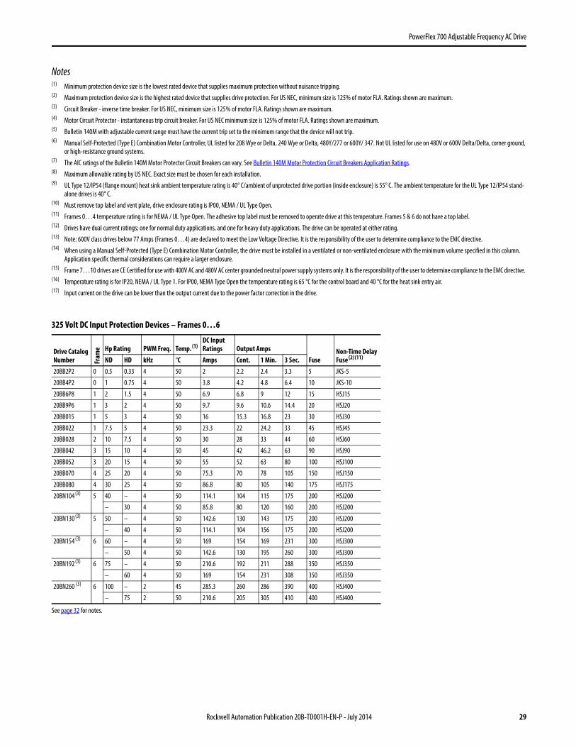
325 Volt DC Input Protection Devices – Frames 0…6
Drive Catalog Number Fr
ame Hp Rating PWM Freq. Temp. (1)
DC Input Ratings Output Amps
FuseNon-Time Delay Fuse (2) (11)ND HD kHz °C Amps Cont. 1 Min. 3 Sec.
20BB2P2 0 0.5 0.33 4 50 2 2.2 2.4 3.3 5 JKS-5
20BB4P2 0 1 0.75 4 50 3.8 4.2 4.8 6.4 10 JKS-10
20BB6P8 1 2 1.5 4 50 6.9 6.8 9 12 15 HSJ15
20BB9P6 1 3 2 4 50 9.7 9.6 10.6 14.4 20 HSJ20
20BB015 1 5 3 4 50 16 15.3 16.8 23 30 HSJ30
20BB022 1 7.5 5 4 50 23.3 22 24.2 33 45 HSJ45
20BB028 2 10 7.5 4 50 30 28 33 44 60 HSJ60
20BB042 3 15 10 4 50 45 42 46.2 63 90 HSJ90
20BB052 3 20 15 4 50 55 52 63 80 100 HSJ100
20BB070 4 25 20 4 50 75.3 70 78 105 150 HSJ150
20BB080 4 30 25 4 50 86.8 80 105 140 175 HSJ175
20BN104 (3) 5 40 – 4 50 114.1 104 115 175 200 HSJ200
– 30 4 50 85.8 80 120 160 200 HSJ200
20BN130 (3) 5 50 – 4 50 142.6 130 143 175 200 HSJ200
– 40 4 50 114.1 104 156 175 200 HSJ200
20BN154 (3) 6 60 – 4 50 169 154 169 231 300 HSJ300
– 50 4 50 142.6 130 195 260 300 HSJ300
20BN192 (3) 6 75 – 4 50 210.6 192 211 288 350 HSJ350
– 60 4 50 169 154 231 308 350 HSJ350
20BN260 (3) 6 100 – 2 45 285.3 260 286 390 400 HSJ400
– 75 2 50 210.6 205 305 410 400 HSJ400
See page 32 for notes.

30 Rockwell Automation Publication 20B-TD001H-EN-P - July 2014
PowerFlex 700 Adjustable Frequency AC Drive
540 Volt DC Input Protection Devices – Frames 0…6
540 Volt DC Input with Precharge – Frames 7…10
Drive Catalog Number Fr
ame kW Rating PWM Freq. Temp. (1) DC Input Ratings Output Amps
FuseNon-Time Delay Fuse (2) (11)ND HD kHz °C Amps Cont. 1 Min. 3 Sec.
20BC1P3 0 0.37 0.25 4 50 1.3 1.3 1.4 1.9 3 JKS-3
20BC2P1 0 0.75 0.55 4 50 2.1 2.1 2.4 3.2 6 JKS-6
20BC3P5 0 1.5 0.75 4 50 3.7 3.5 4.5 6 8 JKS-8
20BC5P0 0 2.2 1.5 4 50 5.3 5 5.5 7.5 10 JKS-10
20BC8P7 0 4 3 4 50 9.3 8.7 9.9 13.2 15 HSJ15
20BC011 0 5.5 4 4 50 12.6 11.5 13 17.4 20 HSJ20
20BC015 1 7.5 5.5 4 50 16.8 15.4 17.2 23.1 25 HSJ25
20BC022 1 11 7.5 4 50 24 22 24.2 33 40 HSJ40
20BC030 2 15 11 4 50 33.2 30 33 45 50 HSJ50
20BC037 2 18.5 15 4 50 40.9 37 45 60 70 HSJ70
20BC043 3 22 18.5 4 50 47.5 43 56 74 90 HSJ90
20BC056 3 30 22 4 50 61.9 56 64 86 100 HSJ100
20BC072 3 37 30 4 50 (7) 80.5 72 84 112 125 HSJ125
20BC085 (3)(5) 4 45 – 4 45 95.1 85 94 128 150 HSJ150
– 37 4 45 80.5 72 108 144 175 HSJ175
20BH105 (3)(5) 5 55 – 4 50 (4) 120.2 105 116 158 175 HSJ175
– 45 4 50 (4) 95.1 85 128 170 200 HSJ200
20BH140 (3)(5) 5 75 – 4 40 (4) 159 140 154 190 225 HSJ225
– 55 4 40 (4) 120.2 105 158 190 225 HSJ225
20BH170 (3)(5) 6 90 – 4 50 (4) 192.3 170 187 255 300 HSJ300
– 75 4 50 (4) 159 140 210 280 300 HSJ300
20BH205 (3)(5) 6 110 – 4 40 (4) 226 205 220 289 350 HSJ350
– 90 4 40 (4) 192.3 170 255 313 350 HSJ350
20BH260 (3)(5) 6 132 – 2 45 (4) 298 260 286 390 500 HSJ500
– 110 2 50 (4) 226 205 305 410 500 HSJ500
See page 32 for notes.
Drive Catalog Number Fr
ame kW Rating PWM Freq. Temp. DC Input Ratings Output Amps
FuseNon-Time Delay Fuse (2) (11)ND HD kHz °C Amps kW Cont. 1 Min. 3 Sec.
20BP292 7 160 4 40 342 185 292 322 438 500 170M6608 (10)
150 4 40 309 166 263 395 526 630 170M6610 (10)
20BP325 7 180 4 40 381 206 325 358 488 630 170M6610 (10)
180 4 40 381 206 325 488 650 800 170M6612 (10)
20BP365 8 200 2 40 428 231 365 402 548 630 170M6610 (10)
180 2 40 381 206 325 488 650 800 170M6612 (10)
20BP415 8 240 2 40 487 262 415 457 623 800 170M6612 (10)
200 2 40 428 231 365 548 730 900 170M6613 (10)
20BP481 8 280 2 40 564 304 481 530 722 900 170M6613 (10)
240 2 40 487 262 415 623 830 1000 170M6614 (10)
20BP535 8 300 2 40 627 338 535 589 803 1000 170M6614 (10)
280 2 40 564 304 481 722 962 1100 170M6615 (10)
20BP600 8 350 2 40 703 379 600 660 900 1100 (8) 170M6615 (10)
300 2 40 627 338 535 803 1070 1200 (8) 170M6616 (10)
20BP730 9 400 2 40 855 461 730 803 1095 1200 (9) 170M6616 (10)
350 2 40 703 379 600 900 1200 1400 (9) 170M6617 (10)
20BH875No Precharge
10 500 2 40 1025 553 875 963 1313 2 x 800 170M6612 (10)
400 2 40 820 443 700 1050 1400 2 x 800 170M6612 (10)
See page 32 for notes.
Rockwell Automation Publication 20B-TD001H-EN-P - July 2014 31
PowerFlex 700 Adjustable Frequency AC Drive
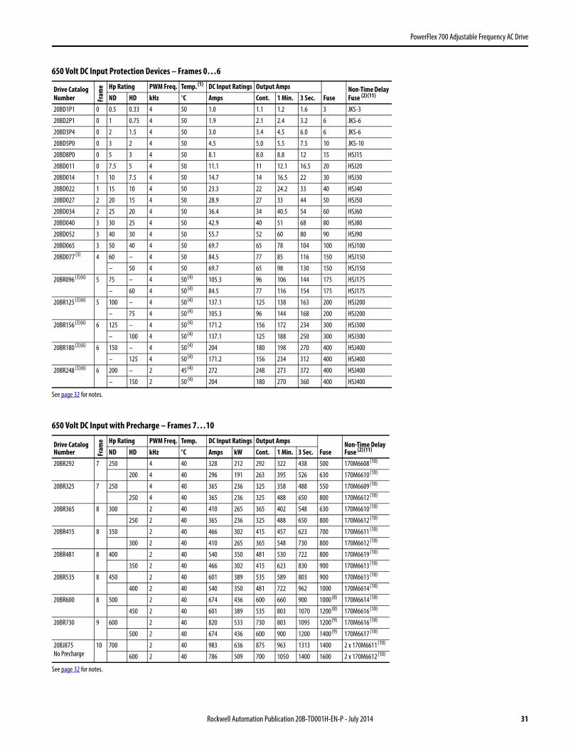
650 Volt DC Input Protection Devices – Frames 0…6
650 Volt DC Input with Precharge – Frames 7…10
Drive Catalog Number Fr
ame Hp Rating PWM Freq. Temp. (1) DC Input Ratings Output Amps
FuseNon-Time Delay Fuse (2) (11)ND HD kHz °C Amps Cont. 1 Min. 3 Sec.
20BD1P1 0 0.5 0.33 4 50 1.0 1.1 1.2 1.6 3 JKS-3
20BD2P1 0 1 0.75 4 50 1.9 2.1 2.4 3.2 6 JKS-6
20BD3P4 0 2 1.5 4 50 3.0 3.4 4.5 6.0 6 JKS-6
20BD5P0 0 3 2 4 50 4.5 5.0 5.5 7.5 10 JKS-10
20BD8P0 0 5 3 4 50 8.1 8.0 8.8 12 15 HSJ15
20BD011 0 7.5 5 4 50 11.1 11 12.1 16.5 20 HSJ20
20BD014 1 10 7.5 4 50 14.7 14 16.5 22 30 HSJ30
20BD022 1 15 10 4 50 23.3 22 24.2 33 40 HSJ40
20BD027 2 20 15 4 50 28.9 27 33 44 50 HSJ50
20BD034 2 25 20 4 50 36.4 34 40.5 54 60 HSJ60
20BD040 3 30 25 4 50 42.9 40 51 68 80 HSJ80
20BD052 3 40 30 4 50 55.7 52 60 80 90 HSJ90
20BD065 3 50 40 4 50 69.7 65 78 104 100 HSJ100
20BD077 (3) 4 60 – 4 50 84.5 77 85 116 150 HSJ150
– 50 4 50 69.7 65 98 130 150 HSJ150
20BR096 (3)(6) 5 75 – 4 50 (4) 105.3 96 106 144 175 HSJ175
– 60 4 50 (4) 84.5 77 116 154 175 HSJ175
20BR125 (3)(6) 5 100 – 4 50 (4) 137.1 125 138 163 200 HSJ200
– 75 4 50 (4) 105.3 96 144 168 200 HSJ200
20BR156 (3)(6) 6 125 – 4 50 (4) 171.2 156 172 234 300 HSJ300
– 100 4 50 (4) 137.1 125 188 250 300 HSJ300
20BR180 (3)(6) 6 150 – 4 50 (4) 204 180 198 270 400 HSJ400
– 125 4 50 (4) 171.2 156 234 312 400 HSJ400
20BR248 (3)(6) 6 200 – 2 45 (4) 272 248 273 372 400 HSJ400
– 150 2 50 (4) 204 180 270 360 400 HSJ400
See page 32 for notes.
Drive Catalog Number Fr
ame Hp Rating PWM Freq. Temp. DC Input Ratings Output Amps
FuseNon-Time Delay Fuse (2) (11)ND HD kHz °C Amps kW Cont. 1 Min. 3 Sec.
20BR292 7 250 4 40 328 212 292 322 438 500 170M6608 (10)
200 4 40 296 191 263 395 526 630 170M6610 (10)
20BR325 7 250 4 40 365 236 325 358 488 550 170M6609 (10)
250 4 40 365 236 325 488 650 800 170M6612 (10)
20BR365 8 300 2 40 410 265 365 402 548 630 170M6610 (10)
250 2 40 365 236 325 488 650 800 170M6612 (10)
20BR415 8 350 2 40 466 302 415 457 623 700 170M6611 (10)
300 2 40 410 265 365 548 730 800 170M6612 (10)
20BR481 8 400 2 40 540 350 481 530 722 800 170M6619 (10)
350 2 40 466 302 415 623 830 900 170M6613 (10)
20BR535 8 450 2 40 601 389 535 589 803 900 170M6613 (10)
400 2 40 540 350 481 722 962 1000 170M6614 (10)
20BR600 8 500 2 40 674 436 600 660 900 1000 (8) 170M6614 (10)
450 2 40 601 389 535 803 1070 1200 (8) 170M6616 (10)
20BR730 9 600 2 40 820 533 730 803 1095 1200 (9) 170M6616 (10)
500 2 40 674 436 600 900 1200 1400 (9) 170M6617 (10)
20BJ875No Precharge
10 700 2 40 983 636 875 963 1313 1400 2 x 170M6611 (10)
600 2 40 786 509 700 1050 1400 1600 2 x 170M6612 (10)
See page 32 for notes.

32 Rockwell Automation Publication 20B-TD001H-EN-P - July 2014
PowerFlex 700 Adjustable Frequency AC Drive
810 Volt DC Input Protection Devices – Frames 0…6
932 Volt DC Input Protection Devices – Frames 0…6
Notes(1) Frames 0…4 temperature rating is for NEMA / UL Type Open. The adhesive top label must be removed to operate drive at this temperature. Frames 5 & 6 do not have a top label.(2) The power source to common bus inverters must be derived from AC voltages 600V or less, as defined in NFPA70; Art 430-18 (NEC). Battery supplies or MG sets are not included. The following devices were
validated to break current of the derived power DC Bus.Disconnects: Allen-Bradley Bulletin 1494, 30-400A; 194, 30-400A; or ABB OESA, 600 & 800A; OESL, all sizes.Fuses: Bussmann Type JKS, all sizes; Type 170M, Case Sizes 1, 2 and 3, or Ferraz Shawmut Type HSJ, all sizes. For any other devices, please contact the factory.
(3) Drives have dual current ratings; one for normal duty applications, and one for heavy duty applications. The drive can be operated at either rating.(4) UL Type 12/IP54 (flange mount) heatsink ambient temperature rating is 40 °C/ambient of unprotected drive portion (inside enclosure) is 55 °C. The ambient temperature for the UL Type 12/IP54 stand-
alone drives is 40 °C.(5) Also applies to “P” voltage class.(6) Also applies to “J” voltage class.(7) Must remove top label and vent plate, drive enclosure rating is IP00, NEMA / UL Type Open.(8) Two 630A Bussmann 170M6608 can also be used.(9) Two 700A Bussmann 170M6611 can also be used.(10) Bussmann or equivalent. (11) See Fuse Certification and Test Data in PowerFlex AC Drives in Common Bus Configurations Application Guidelines, publication DRIVES-AT002, for fuse self-certification and test data for Bussmann 170M
and JKS fuses recommended for the DC bus fusing.
Drive Catalog Number Fr
ame Hp Rating PWM Freq. Temp. (1) DC Input Ratings Output Amps
FuseNon-Time Delay Fuse (2) (11)ND HD kHz °C Amps Cont. 1 Min. 3 Sec.
20BE1P7 0 1 0.75 4 50 1.5 1.7 2 2.6 3 JKS-3
20BE2P7 0 2 1.5 4 50 2.4 2.7 3.6 4.8 6 JKS-6
20BE3P9 0 3 2 4 50 3.5 3.9 4.3 5.9 6 JKS-6
20BE6P1 0 5 3 4 50 6.2 6.1 6.7 9.2 10 JKS-10
20BE9P0 0 7.5 5 4 50 9.1 9 9.9 13.5 15 HSJ15
20BE011 0 10 7.5 4 50 11.5 11 13.5 18 20 HSJ20
20BE017 1 15 10 4 50 18 17 18.7 25.5 30 HSJ30
20BE022 2 20 15 4 50 23.6 22 25.5 34 40 HSJ40
20BE027 2 25 20 4 50 29 27 33 44 50 HSJ50
20BE032 3 30 25 4 50 34.3 32 40.5 54 60 HSJ60
20BE041 3 40 30 4 50 43.9 41 48 64 70 HSJ70
20BE052 3 50 40 4 50 55.7 52 61.5 82 90 HSJ90
20BE062 4 60 50 2 50 68 62 78 104 125 HSJ125
20BT099 (3) 5 100 – 2 40 108.6 99 109 126 150 HSJ150
– 75 2 40 84.5 77 116 138 150 HSJ150
20BT144 (3) 6 150 – 2 50 158 144 158 216 250 HSJ250
– 125 2 50 137.1 125 188 250 250 HSJ250
Drive Catalog Number Fr
ame kW Rating PWM Freq. Temp. (1) DC Input Ratings Output Amps
FuseNon-Time Delay Fuse (2) (11)ND HD kHz °C Amps Cont. 1 Min. 3 Sec.
20BW052 (3) 5 45 – 2 50 (4) 58.2 52 57 78 100 170M3691
– 37.5 2 50 (4) 46.9 46 69 92 100 170M3691
20BW098 (3) 5 90 – 2 50 (4) 110.7 98 108 127 160 170M3693
– 75 2 50 (4) 92.3 82 123 140 160 170M3693
20BW142 (3) 6 132 – 2 50 (4) 162.2 142 156 213 250 170M3695
– 110 2 40 (4) 134.9 119 179 238 315 170M3696

Rockwell Automation Publication 20B-TD001H-EN-P - July 2014 33
PowerFlex 700 Adjustable Frequency AC Drive
Cable Recommendations
Power Cable Types Acceptable for 200…600 Volt InstallationsA variety of cable types are acceptable for drive installations. For many installations, unshielded cable is adequate, provided it can be separated from sensitive circuits. As an approximate guide, allow a spacing of 0.3 meters (1 foot) for every 10 meters (32.8 feet) of length. In all cases, long parallel runs must be avoided. Do not use cable with an insulation thickness less than or equal to 15 mils (0.4mm/0.015 in.). Use Copper wire only. Wire gauge requirements and recommendations are based on 75° C. Do not reduce wire gauge when using higher temperature wire. See table below.
Unshielded
THHN, THWN or similar wire is acceptable for drive installation in dry environments provided adequate free air space and/or conduit fill rates limits are provided. Do not use THHN or similarly coated wire in wet areas. Any wire chosen must have a minimum insulation thickness of 15 Mils and should not have large variations in insulation concentricity.
Shielded/Armored Cable
Shielded cable contains all of the general benefits of multi-conductor cable with the added benefit of a copper braided shield that can contain much of the noise generated by a typical AC drive. Strong consideration for shielded cable should be given in installations with sensitive equipment such as weigh scales, capacitive proximity switches and other devices that may be affected by electrical noise in the distribution system. Applications with large numbers of drives in a similar location, imposed EMC regulations or a high degree of communications/ networking are also good candidates for shielded cable.
Shielded cable may also help reduce shaft voltage and induced bearing currents for some applications. In addition, the increased impedance of shielded cable may help extend the distance that the motor can be located from the drive without the addition of motor protective devices such as terminator networks.
Consideration should be given to all of the general specifications dictated by the environment of the installation, including temperature, flexibility, moisture characteristics and chemical resistance. In addition, a braided shield should be included and be specified by the cable manufacturer as having coverage of at least 75%. An additional foil shield can greatly improve noise containment.
A good example of recommended cable is Belden® 295xx (xx determines gauge). This cable has four (4) XLPE insulated conductors with a 100% coverage foil and an 85% coverage copper braided shield (with drain wire) surrounded by a PVC jacket.
Location Rating/Type Description
Standard (Option 1) 600V, 90°C (194°F)XHHW2/RHW-2Anixter B209500-B209507, Belden 29501-29507, or equivalent
• Four tinned copper conductors with XLP insulation.• Copper braid/aluminum foil combination shield and tinned copper drain wire.• PVC jacket.
Standard (Option 2) Tray rated 600V, 90° C (194° F) RHH/RHW-2Anixter OLF-7xxxxx or equivalent
• Three tinned copper conductors with XLPE insulation.• 5 mil single helical copper tape (25% overlap min.) with three bare copper grounds
in contact with shield.• PVC jacket.
Class I & II;Division I & II
Tray rated 600V, 90° C (194° F) RHH/RHW-2Anixter 7V-7xxxx-3G or equivalent
• Three bare copper conductors with XLPE insulation and impervious corrugated continuously welded aluminum armor.
• Black sunlight resistant PVC jacket overall.• Three copper grounds on #10 AWG and smaller.

34 Rockwell Automation Publication 20B-TD001H-EN-P - July 2014
PowerFlex 700 Adjustable Frequency AC Drive
Other types of shielded cable are available, but the selection of these types may limit the allowable cable length. Particularly, some of the newer cables twist 4 conductors of THHN wire and wrap them tightly with a foil shield. This construction can greatly increase the cable charging current required and reduce the overall drive performance. Unless specified in the individual distance tables as tested with the drive, these cables are not recommended and their performance against the lead length limits supplied is not known.
Maximum Motor Cable LengthsFor information on maximum motor cable lengths, refer to the Wiring and Grounding Guidelines for Pulse Width Modulated (PWM) AC Drives, publication DRIVES-IN001.
Power WiringThe PowerFlex 700 has the following built in protective features to help simplify installation:
• Ground fault protection during start up and running ensures reliable operation• Electronic motor overload protection increases motor life• Removable MOV to ground and common mode capacitors to ground ensure compatibility with ungrounded
systems. These devices must be disconnected if the drive is installed on a resistive grounded distribution system, an ungrounded distribution system, a B phase grounded distribution system or impedance grounded system. These devices must also be disconnected if the drive power source is a regenerative unit (such as a bus supply and brake) or is DC fed from an active converter.
• 6 kV transient protection provides increased robustness for 380…480V system voltages
There are many other factors that must be considered for optimal performance in any given application. The block diagram below highlights the primary installation considerations. Consult the Wiring and Grounding Guidelines for Pulse Width Modulated (PWM) AC Drives, publication DRIVES-IN001 for detailed recommendations on input power conditioning, dynamic braking, reflected wave protection and motor cable types.
Branch Circuit Protective Devices - Page 24
Input Power Conditioning - Page 81
EMC Requirements
LCD Human Interface Module - Page 78
Reflected Wave Reduction - Page 80Cable Requirements - Page 33Integral Class 10 Motor Overload
Motor Recommendationssee Allen-Bradley Industrial Motors, publication MOTORS-PP006.
Removable MOV and Caps (underneath cover)
Input Fuses - Page 24
Input Cable Length - Page 34
Same as AC
Same as AC
AC Input
Not Used
DC Input

Rockwell Automation Publication 20B-TD001H-EN-P - July 2014 51
PowerFlex 700 Adjustable Frequency AC Drive
Operating TemperaturesPowerFlex 700 drives are designed to operate at 0°to 40° C ambient. To operate the drive in installations between 41° and 50° C, see the information below and refer to pages 25…32 for exceptions.
Acceptable Surrounding Air Temperature & Required Actions
Enclosure Rating Temperature Range Drive
IP20, NEMA / UL Type 1 (with Top Label) (1)
(1) Removing the adhesive top label from the drive changes the NEMA / UL enclosure rating from Type 1 to Open. Frames 5 and 6 do not have a top label.
0…40 °C (0…104 °F) Frames 0…4, All Ratings
0…50 °C (0…122 °F) Frames 5…6, Most Ratings (2)
(2) Refer to pages 25…32 for exceptions.
IP20, NEMA / UL Type Open (Top Label Removed) (1)
0…50 °C (0…122 °F) Frames 0…6, Most Ratings (2)
0…45 °C (0…113 °F) 20BC072 Only
IP00, NEMA / UL Type Open (Top Label & Vent Plate Removed)
0…50 °C (0…122 °F) 20BC072 Only (3)
(3) To remove vent plate (see page 53 for location), lift top edge of plate from the chassis. Rotate the plate out from the back plate.
Flange Mount Front: IP00, NEMA / UL Type OpenBack/Heat Sink: IP54, NEMA / UL Type 12
0…55 °C (0…131 °F) Front (Inside Encl.)0…40 °C (0…104 °F) Back (External)
Frames 5…6
Stand-alone/Wall MountIP54, NEMA / UL Type 12
0…40 °C (0…104 °F) Frames 5…6
IP20, NEMA / UL Type 1 0…40 °C (0…104 °F) Frames 7…10
IP00, NEMA / UL Type Open/Flange MountFront: IP00, NEMA / UL Type OpenBack/Heat Sink: IP54, NEMA12
0…65 °C (0…149 °F) Control Board0…40 °C (0…104 °F) Heat Sink Entry Air
Frames 7…10
Roll InFront: IP00, NEMA / UL Type OpenBack/Heat Sink: IP54, NEMA12
0…65 °C (0…149 °F) Control Board0…40 °C (0…104 °F) Heat Sink Entry Air
Frames 8…9

52 Rockwell Automation Publication 20B-TD001H-EN-P - July 2014
PowerFlex 700 Adjustable Frequency AC Drive
Minimum Mounting Clearances
Frames 0…6
Specified vertical clearance requirements (indicated above) are intended to be from the drive to the closest object that can restrict airflow through the drive heat sink and chassis. The drive must be mounted in a vertical orientation as shown and must make full contact with the mounting surface. Do not use standoffs or spacers. In addition, inlet air temperature must not exceed the product specification.
Frames 7…10
The drive must be mounted with sufficient space at the top, sides, and front of the cabinet to allow for proper heat dissipation.
Frame Recommendations
7 Minimum of 152 mm (6.0 in.) at the top and bottom of the enclosure and 102 mm (4.0 in.) on the sides.Flange Mount - Minimum of 152 mm (6.0 in.) at the back of the enclosure (flange mount surface to wall).
8…10 Minimum of 152 mm (6.0 in.) at the top of the enclosure. Additionally, allow a minimum of 102 mm (4.0 in.) on each side OR 152 mm (6.0 in.) in the back.Flange Mount - Minimum of 102 mm (4.0 in.) on each side.
101.6 mm(4.0 in.)
101.6 mm(4.0 in.)
101.6 mm 101.6 mm
PWR
STS
PORT
MOD
NET A
NET B
PWR
STS
PORT
MOD
NET A
NET B
101.6 mm(4.0 in.)
101.6 mm(4.0 in.)
50.8 mm(2.0 in.)
101.6 mm 101.6 mm
PWR
STS
PORT
MOD
NET A
NET B
PWR
STS
PORT
MOD
NET A
NET B
Airflow through the drive must not be impeded.
Refer to pages 53 through 62 for detailed dimension information.
No Adhesive Label(see page 51)
With Adhesive Label(see page 51)

Rockwell Automation Publication 20B-TD001H-EN-P - July 2014 53
PowerFlex 700 Adjustable Frequency AC Drive
Dimensions and WeightsFrames 0…3 – IP20, NEMA / UL Type 1
.
C
A
D15.0 (0.59)
5.8 (0.23) dia.
E
8.0
(0.31)
5.5 (0.22) x 3 - Frames 0…1
7.0 (0.28) x 3 - Frames 2…3
B
HOT surfaces can cause severe burns
CAUTION
Frame 0 Shown
Fram
e
A B C D E
Weight (1) kg (lbs.)
(1) Weights include HIM and Standard I/O.
DriveDrive & Packaging
0 110.0 (4.33) 336.0 (13.23) 200.0 (7.87) 80.0 (3.15) 320.0 (12.60) 5.22 (11.5) 8.16 (18)
1 135.0 (5.31) 336.0 (13.23) 200.0 (7.87) 105.0 (4.13) 320.0 (12.60) 7.03 (15.5) 9.98 (22)
2 222.0 (8.74) 342.5 (13.48) 200.0 (7.87) 192.0 (7.56) 320.0 (12.60) 12.52 (27.6) 15.20 (33.5)
3 222.0 (8.74) 517.5 (20.37) 200.0 (7.87) 192.0 (7.56) 495.0 (19.49) 18.55 (40.9) 22.68 (50)
Dimensions are in millimeters and (inches)
94.7 (3.73)
105.3 (4.15)
127.7(5.03)
151.1(5.95)
160.1(6.30)
165.1(6.50)
184.5(7.26)
22.2 (0.87) Dia.
28.7 (1.13) Dia.2 Places
37.3 (1.47) Dia.2 Places
66.0 (2.60)
97.0 (3.82)
137.2 (5.40)
187.0 (7.36)
22.7 (0.89)
29.0 (1.14)
Frame 3All except 50 Hp, 480V (37 kW, 400V)
94.7 (3.73)
105.3 (4.15)
127.7(5.03)
160.1(6.30)
165.1(6.50)
184.5(7.26)
28.7 (1.13) Dia.2 Places
46.7 (1.84) Dia.2 Places
34.9 (1.37) Dia.2 Places
Vent Plate
66.0 (2.60)
130.0 (5.12)
186.0 (7.32)
22.7 (0.89)
29.0 (1.14)
Frame 350 Hp, 480V (37 kW, 400V) Normal Duty Drive
132.9(5.23)
187.5(7.38)
30.2(1.19)
41.9 (1.65)
56.1 (2.21)
96.0 (3.78)
75.9 (2.99)
96.0 (3.78)
55.0 (2.17)
75.0 (2.95)
35.0 (1.38)22.2 (0.87) Dia.4 Places
185.0(7.28)
133.3(5.25)
187.6(7.39)
25.5(1.00)
22.2 (0.87) Dia.3 Places
185.1(7.29)
162.3(6.39)
43.0 (1.69)
70.0 (2.76)
96.0 (3.78)
75.9 (2.99)
28.6 (1.13) Dia.
108.5 (4.27)
67.5 (2.66)
47.5 (1.87)
87.5 (3.44)
167.5 (6.59)
156.9 (6.18)
150.9(5.94)
184.8(7.28)
157.5(6.20)
112.1(4.41)
22.4 (0.88) Dia.2 Places
28.7 (1.13) D3 Places
39.3 (1.55)
57.2 (2.25)
72.7 (2.86)
106.0 (4.17)
139.4 (5.49)
177.4 (6.98)
Frame 2Frame 1Frame 0

54 Rockwell Automation Publication 20B-TD001H-EN-P - July 2014
PowerFlex 700 Adjustable Frequency AC Drive
Frame 4 – IP20, NEMA / UL Type 1
Fram
e Approx. Weight (1) kg (lbs.)
(1) Weights include HIM and Standard I/O.
Drive Drive & Packaging4 24.49 (54.0) 29.03 (64.0)
201.7 (7.94)
738.2(29.06)
8.0(0.31)
758.8(29.87)
7.0 (0.28) dia.
7.0 (0.28) x 3
220.0 (8.66)
192.0 (7.56)15.0 (0.59)
Lifting Holes x 4
Dimensions are in millimeters and (inches)
54.1 (2.13) Dia.2 Places
47.0 (1.85) Dia.2 Places
28.7 (1.13) Dia.2 Places
141.9(5.59)
105.1(4.14)
157.9(6.21)
177.9(7.00)
189.7(7.47)
22.2 (0.87) Dia.
26.8 (1.06)
36.8 (1.45)
50.7 (2.00)
63.8 (2.51)
112.0 (4.41)
180.0 (7.09)
65.3 (2.57)
76.0 (2.99)

Rockwell Automation Publication 20B-TD001H-EN-P - July 2014 55
PowerFlex 700 Adjustable Frequency AC Drive
Frame 5 – IP20, NEMA / UL Type 1Fr
ame Approx. Weight (1) kg (lbs.)
(1) Weights include HIM and Standard I/O. Add 2.70 kg (6.0 lbs.) for the 20BC140 drive.
Drive Drive & Packaging5 37.19 (82.0) 49.50 (109.0)
HOT surfaces can cause severe burns
CAUTION
625.0 (24.61)
12.5(0.49)
6.5(0.26)
644.5(25.37)
225.0 (8.86)
308.9 (12.16)
259.1 (10.20)
15.0 (0.59)
6.5 (0.26)
37.6 (1.48)
617.0 (24.29)
689.6(27.15)
275.4 (10.84)
Lifting Holes x 412.7 (0.50) Dia.
Junction Box
Dimensions are in millimeters and (inches)
96.0(3.78)
159.5(6.28)
184.0(7.24)
220.0(8.66)
229.5(9.04)
241.9(9.52)
93.2 (3.67)
104.0 (4.09)22.2 (0.87) Dia.2 Places
62.7 (2.47) Dia.2 Places
34.9 (1.37) Dia.2 Places
45.0 (1.77)
85.0 (3.35)
150.0 (5.91)
215.0 (8.46)
255.0 (10.04)
28.0 (1.10)
96.0(3.78)
153.5(6.04)
184.3(7.26)
188.5(7.42)
223.5(8.80)
241.9(9.52)
31.9 (1.26)
42.6 (1.68) 22.2 (0.87) Dia.2 Places
62.7 (2.47) Dia.2 Places
Removable Junction Box
34.9 (1.37) Dia.
44.0 (1.73)
66.4 (2.61)
128.0 (5.04)
232.3 (9.15)
28.0 (1.10)
30 kW, 208V (40 Hp, 240V)55 kW, 400V (75 Hp, 480V)
45/55/75 kW, 690V (75 Hp, 600V)
37 kW, 208V (50 Hp, 240V)75 kW, 400V (100 Hp, 480V)90kW, 690V (100 Hp, 600V)

56 Rockwell Automation Publication 20B-TD001H-EN-P - July 2014
PowerFlex 700 Adjustable Frequency AC Drive
Frame 5 – IP54, NEMA Type 12 Standalone (400…690V drives only)
Fram
e
DescriptionApprox. Weight (1) kg (lbs.)
(1) Weights include HIM and Standard I/O.
Drive Drive & Packaging5 Standalone 102.51 (226.0) 154.68 (341.0)
609.6 (24.00)
25.4 (1.00)
105.5 (4.15)
1574.8 (62.00)
1061.5 (41.79)
16.8 (0.66)
1543.0 ±1.5 (62.75 ±0.06)
450.7 (17.75)
Max. 425.5(16.75)
287.0(11.30)
558.8 (22.00)
REMOTE SOURCE(S) OF POWER.DISCONNECT ALL SOURCES OF POWERBEFORE OPENING THE DOOR.
DANGER
DANGERELECTRICAL SHOCK HAZARD FROMENERGY STORAGE CAPACITORS.VERIFY LOW VOLTAGE DISCHARGEBEFORE SERVICING.SEE INSTRUCTION MANUAL.
13.5 (0.53) Dia. x 4 12.7 (0.50) Dia.Lifting Holes
140.0(5.51)
AirOutlet
Mount with 0.50 in. UNC Grade 5 or higher screwsor
M12 Material Class 5.6 or higher screws.Use flat washer with each fastener.
Dimensions are in millimeters and (inches)

Rockwell Automation Publication 20B-TD001H-EN-P - July 2014 57
PowerFlex 700 Adjustable Frequency AC Drive
Frame 5 – IP54, NEMA Type 12 Flange Mount (400…690V drives only)Fr
ame
DescriptionApprox. Weight (1) kg (lbs.)
(1) Weights include HIM and Standard I/O.
Drive Drive & Packaging5 Flange Mount 61.69 (136.0) 81.65 (180.0)
303.6(11.95)
2.3 (0.09)Compressed
Gasket
97.0(3.82)
384.0 (15.12)42.0 (1.65)
1061.0(41.77)
1039.0(40.91)
11.0 (0.43)
500.0 (19.69)
478.0 (18.82)
5.5 (0.22) Dia. x 40
12.7 (0.50) Dia. Lifting Holes x 4
AirOutlet
11.0 (0.43)
53.2(2.09)
USE 75 C CU WIRE ONLY
WIRE RANGE: 4-3/0 AWG (18-70 MM2)
TORQUE: 133 IN-LB (15 N-M)
STRIP LENGTH: 1.02 IN (26 MM)
POWER & DC TERMINAL RATINGS
WIRE RANGE: 14-1/0 AWG (2.5-50 MM2)
TORQUE: 32 IN-LB (3.6 N-M)
STRIP LENGTH: 0.67 IN (17 MM)
BRAKE TERMINAL RATINGS
WIRE RANGE: 6-1/0 AWG (18-35 MM2)
TORQUE: 44 IN-LB (5 N-M)
STRIP LENGTH: 0.83 IN (21 MM)
GROUND TERMINAL RATINGS (PE)
OUTPUT INPUT AC
300 VDC EXT PWR SPLY TERM (PS+, PS-)
WIRE RANGE: 22-10 AWG (0.5-4 MM2)
TORQUE: 5.3 IN-LB (0.6 N-M)
STRIP LENGTH: 0.35 IN (9 MM)
DANGER
DANGER
RISK OF ELECTRIC
SHOCK AND DEATH
FIELD INSTALLED OPTIONS
6 MM HEX KEY6 MM HEX KEY
SHLD
SHLD
219.5 (8.64)
196.5 (7.74)
185.0(7.30)
449.6(17.74)
127.6(5.02)
194.0(7.60)
GroundM5 PEM Nut
Dimensions are in millimeters and (inches)

58 Rockwell Automation Publication 20B-TD001H-EN-P - July 2014
PowerFlex 700 Adjustable Frequency AC Drive
Frame 5 – Flange Mount Cutout
10.0(0.39)
458.0 (18.03)
1019.0(40.12)
Cutout
1039.0(40.91)
1026.5 (40.41)
948.5 (37.34)
870.5 (34.27)
792.5 (31.20)
714.5 (28.13)
636.5 (25.06)
558.5 (21.99)
480.5 (18.92)
402.5 (15.85)
324.5 (12.78)
246.5 (9.71)
168.5 (6.63)
90.5(3.56)
12.5 (0.49) 10.0(0.39)59.0 (2.32)
131.0 (5.16)
203.0 (7.99)
275.0 (10.83)
347.0 (13.66)
419.0 (16.50)
478.0 (18.82)
4.00 (0.157) Dia. x 40, minimum 14GA. (1.9) steel mounting surface.
Deburr Pilot Holes and Drive Cutout.
Dimensions are in millimeters and (inches)

Rockwell Automation Publication 20B-TD001H-EN-P - July 2014 59
PowerFlex 700 Adjustable Frequency AC Drive
Frame 6 – IP20, NEMA / UL Type 1Fr
ame Approx. Weight (1) kg (lbs.)
(1) Weights include HIM and Standard I/O. Add 13.60 kg (30.0 lbs.) for; 20BB260, 20BC260 and 20BD248.
Drive Drive & Packaging6 71.44 (157.5) 100.9 (222.0)
825.0(32.48)
13.5(0.53)
126.3(4.97)
8.5(0.33)
850.0(33.46)
Lifting Holes x 412.7 (0.50) Dia.
300.0 (11.81) 275.5 (10.85)
403.9 (15.90)
360.6 (14.20)
18.0 (0.71)
8.5 (0.33)
49.6 (1.95)
New Style Junction Box
Old Style Junction Box
Dimensions are in millimeters and (inches)Junction Box can be removed if drive is mounted in a cabinet
116.6(4.59)
148.5(5.85)
222.3(8.75)
242.0(9.53) 219.0
(8.62)
185.4(7.30)
151.8(5.98)
45.6 (1.80)
56.2 (2.21)
Removable Junction Box
22.2 (0.87) Dia.4 Places
62.7 (2.47) Dia.3 Places
34.9 (1.37) Dia.3 Places
52.1 (2.05)
69.1 (2.72)
130.1 (5.12)
280.1 (11.03)
330.1 (13.00)
230.1 (9.06)
47.1 (1.85)
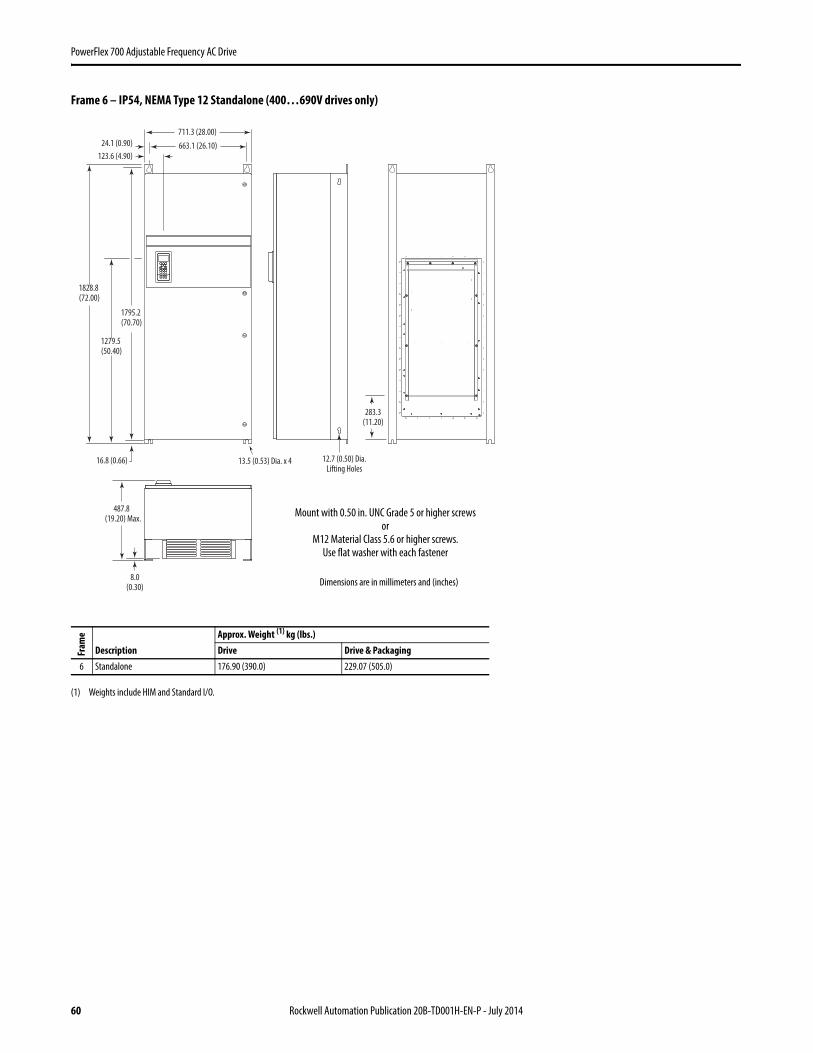
60 Rockwell Automation Publication 20B-TD001H-EN-P - July 2014
PowerFlex 700 Adjustable Frequency AC Drive
Frame 6 – IP54, NEMA Type 12 Standalone (400…690V drives only)Fr
ame
DescriptionApprox. Weight (1) kg (lbs.)
(1) Weights include HIM and Standard I/O.
Drive Drive & Packaging6 Standalone 176.90 (390.0) 229.07 (505.0)
663.1 (26.10)24.1 (0.90)
123.6 (4.90)
1828.8(72.00)
1279.5 (50.40)
16.8 (0.66)
1795.2 (70.70)
487.8 (19.20) Max.
711.3 (28.00)
13.5 (0.53) Dia. x 4 12.7 (0.50) Dia.Lifting Holes
283.3(11.20)
8.0(0.30)
Mount with 0.50 in. UNC Grade 5 or higher screwsor
M12 Material Class 5.6 or higher screws. Use flat washer with each fastener
Dimensions are in millimeters and (inches)
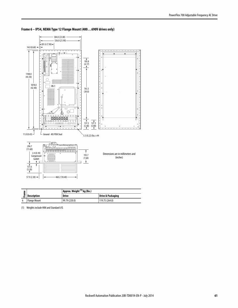
Rockwell Automation Publication 20B-TD001H-EN-P - July 2014 61
PowerFlex 700 Adjustable Frequency AC Drive
Frame 6 – IP54, NEMA Type 12 Flange Mount (400…690V drives only)Fr
ame
DescriptionApprox. Weight (1) kg (lbs.)
(1) Weights include HIM and Standard I/O.
Drive Drive & Packaging6 Flange Mount 99.79 (220.0) 119.75 (264.0)
UT1
DC-DC+BR1BR2 VT2
WT3
RL1
SL2
OUTPUT
TL3
PE PE
USE 75C COPPER WIRE ONLY, TORQUE 52 IN-LB (6 N-M)22-1
2 AW
G5.
3 IN
-LB
(0.6
N-M
)
PS+
PS-
WIR
E ST
RIP
584.0 (23.00)
14.0 (0.60)
556.0 (21.90)
201.0 (7.90)
1100.0(43.30)
1078.0(42.40)
11.0 (0.43)5.5 (0.22) Dia. x 44
127.3(5.00)
763.3(30.0)
105.8(4.17)
137.2(5.40)
294.7(11.60)
2.4 (0.10)Compressed
Gasket
131.6(5.20)
468.2 (18.40)57.9 (2.30)
193.7(7.60)
Ground - M5 PEM Stud
Dimensions are in millimeters and (inches)

62 Rockwell Automation Publication 20B-TD001H-EN-P - July 2014
PowerFlex 700 Adjustable Frequency AC Drive
Frame 6 – Flange Mount Cutout
532.0(20.90)
12.0(0.50)
1043.0 (41.10)
971.0 (38.20)
899.0 (35.40)
827.0 (32.60)
755.0 (29.70)
683.0 (26.90)
611.0 (24.10)
539.0 (21.20)
467.0 (18.40)
395.0 (15.60)
323.0 (12.70)
251.0 (9.90)
179.0(7.00)
107.0(4.20)
35.0(1.40)
1078.0 (42.40)
1054.0(41.5)
Cutout
12.0(0.50)44.0 (1.70)
122.0 (4.80)
200.0 (7.90)
278.0 (10.90)
356.0 (14.00)
434.0 (17.10)
512.0 (20.20)
4.00 (0.157) Dia. x 44, minimum14 GA. (1.9) steel mounting surface. Deburr pilot holes and drive cutout.
Dimensions are in millimeters and (inches)
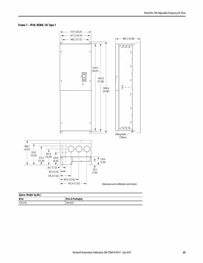
Rockwell Automation Publication 20B-TD001H-EN-P - July 2014 63
PowerFlex 700 Adjustable Frequency AC Drive
Frame 7 – IP20, NEMA / UL Type 1
Approx. Weight kg (lbs.)Drive Drive & Packaging170 (375) 196 (433)
Lifting Holes4 Places
406.7(16.01)
354.3(13.95)
312.4(12.30)
261.6(10.30) 210.8
(8.30)
38.7 (1.52)
89.5 (3.52)
178.4 (7.02)
305.4 (12.02)
432.4 (17.02)
PORT
NET A
NET B
MOD
58.5(2.30)
134.6(5.30)
406.5 (16.00)
1498.6(59.00)
1447.8(57.00)
1424.7(56.01)
514.4 (20.25)
477.3 (18.79)
440.2 (17.33)
Dimensions are in millimeters and (inches)
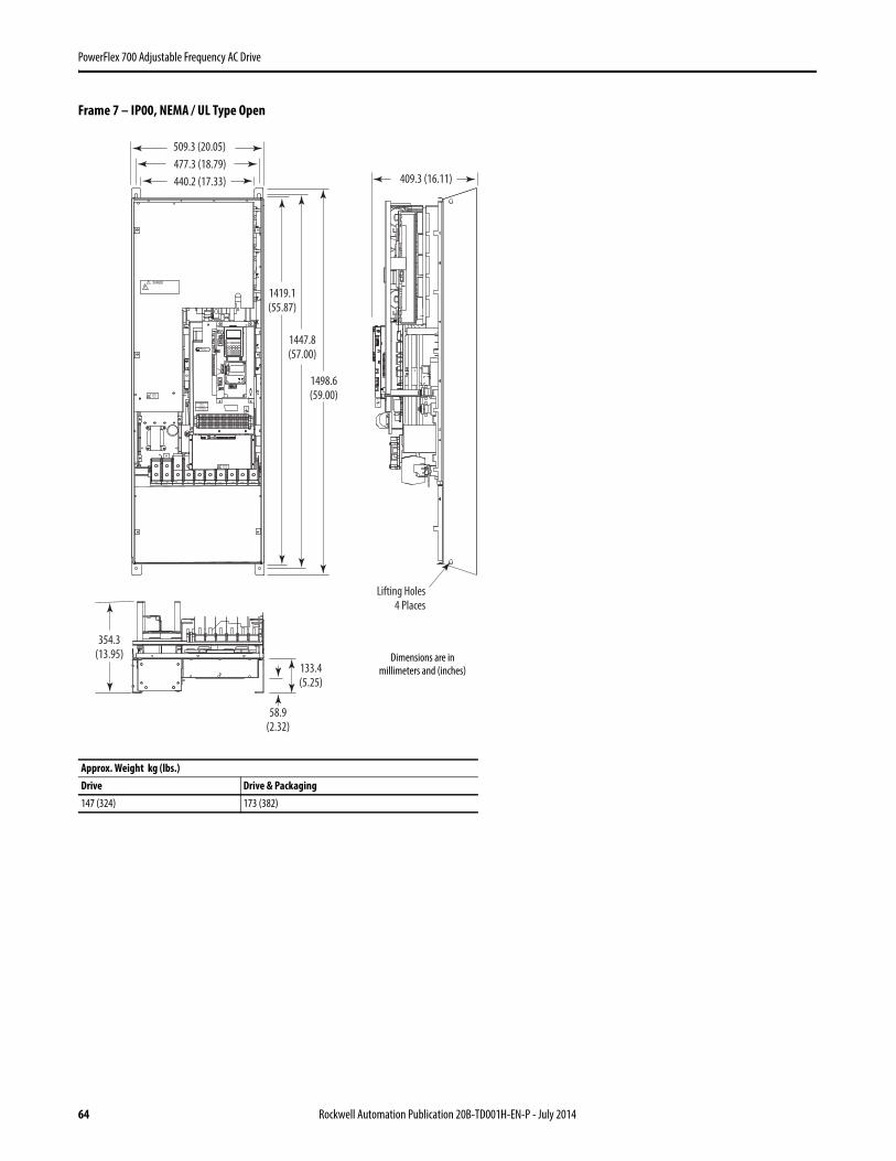
64 Rockwell Automation Publication 20B-TD001H-EN-P - July 2014
PowerFlex 700 Adjustable Frequency AC Drive
Frame 7 – IP00, NEMA / UL Type Open
Approx. Weight kg (lbs.)Drive Drive & Packaging147 (324) 173 (382)
509.3 (20.05)
477.3 (18.79)
440.2 (17.33) 409.3 (16.11)
Lifting Holes
4 Places
354.3
(13.95)
58.9
(2.32)
133.4
(5.25)
1498.6
(59.00)
1447.8
(57.00)
1419.1
(55.87)
+DCUSE 75° COPPER WIRE ONLY TORQUE LARGE TERMINALS TO 10 N-m (87LB-IN)
-DC PE PE R-L1 T-L3
RISK OF SHOCKREPLACE AFTER
SERVICING
! DANGER
U-M1 V-M2 W-M3S-L2
TB1125 AMPERES RMS
MAXIMUM
CAUTION
HOT SURFACES
ALLEN-BRADLEYMADE IN U.S.A.
PE
!
! DANGER
RISK OF SHOCKREPLACE AFTER
SERVICING
! DANGER
Dimensions are in millimeters and (inches)

Rockwell Automation Publication 20B-TD001H-EN-P - July 2014 65
PowerFlex 700 Adjustable Frequency AC Drive
Frame 7 – Flange Mount Cutout
IMPORTANT Use gasket kit catalog number SK-G1-GASKET1-F7 with user supplied IP54, NEMA / UL Type 12 enclosure.
489.0
(19.25)
508.0
(20.00)
477.3
(18.79)
1084.1
(42.68)
1095.8
(43.14)
1422.4
(56.00)
5.8
(0.23)
75.4
(2.97)
127.0
(5.00)
Cutout
26 Required
4.3 (0.171) Dia. for 10-32 x 9.7 (0.38) Self-Tap
4.0 (0.159) for 10-32 x 9.7 (0.38) Threaded
132.3 (5.21) *
5.8
(0.23)
127.0
(5.00)54.1
(2.13)
Back of EnclosureDrive
* Minimum dimension allowed – More space
will improve fan effectiveness and heat
dissipation.
Shading indicates approximate size
of drive inside enclosure.
Dimensions are in millimeters and (inches)

66 Rockwell Automation Publication 20B-TD001H-EN-P - July 2014
PowerFlex 700 Adjustable Frequency AC Drive
Frames 8…9 – IP20, NEMA / UL Type 1
Approx. Weight kg (lbs.)Frame Drive Drive & Packaging8 509 (1122) 556 (1225)
9 526 (1159) 603 (1262)
898.8 (35.39) - 20Bx365, 415, 4811025.9 (40.39) - 20Bx535, 600, 730
254.6 (10.02) - 20Bx365, 415, 481381.7 (15.03) - 20Bx535, 600, 730
757.9(29.84)
2349.1(92.49)
549.7(21.64)
1466.6(57.74)
Dimensions are in millimeters and (inches)
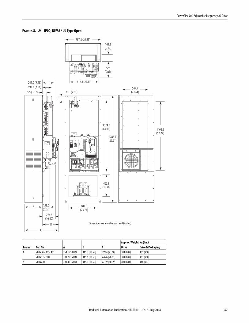
Rockwell Automation Publication 20B-TD001H-EN-P - July 2014 67
PowerFlex 700 Adjustable Frequency AC Drive
Frames 8…9 – IP00, NEMA / UL Type Open
Frame Cat. No. A B CApprox. Weight kg (lbs.)Drive Drive & Packaging
8 20Bx365, 415, 481 254.6 (10.02) 345.3 (13.59) 599.4 (23.60) 384 (847) 431 (950)
20Bx535, 600 381.7 (15.03) 345.5 (13.60) 726.6 (28.61) 384 (847) 431 (950)
9 20Bx730 381.1 (15.00) 345.3 (13.60) 771.9 (30.39) 401 (884) 448 (987)
TB11
TE25 AMPERES RMS
MAXIMUM
RISK OF SHOCKREPLACE AFTER
SERVICING
! DANGER
DANGER
RISK OF SHOCKREPLACE AFTER
SERVICING
! DANGER
TB98 AMPERES RMS
MAXIMUM
DC+
V WU
R S T DC-DC+
GND
2283.7(89.91)
463.8(18.26)
603.0(23.74)
1524.0(60.00)
71.3 (2.81)
A
C
B
153.0(6.02)
274.3(10.80)
193.3 (7.61)
241.0 (9.49)
549.7(21.64)
1466.6(57.74)
85.5 (3.37)
757.8 (29.83)
145.3(5.72)
SeeTable
612.8 (24.13)
Dimensions are in millimeters and (inches)

68 Rockwell Automation Publication 20B-TD001H-EN-P - July 2014
PowerFlex 700 Adjustable Frequency AC Drive
Frames 8…9 – Converting an IP00 Drive for Flange Mounting
No. Component
➊ Remove these IP00 enclosure components.
➋ Drive assembly to be flange mounted.
➌ DC link choke - mounts separately in enclosure (see page 72 for dimensions) and is wired directly to drive.
TB11TE
25 AMPERES RMSMAXIMUM
RISK OF SHOCKREPLACE AFTER
SERVICING
! DANGER
DANGER
RISK OF SHOCKREPLACE AFTER
SERVICING
! DANGER
TB98 AMPERES RMS
MAXIMUM
DC+
V WU
R S T DC-DC+
GND
➊
➋
➌

Rockwell Automation Publication 20B-TD001H-EN-P - July 2014 69
PowerFlex 700 Adjustable Frequency AC Drive
Frames 8…9 Roll-In – IP00, NEMA / UL Type Open
Frame Cat. No. AApprox. Weight kg (lbs.)Drive Drive & Packaging
8 20Bx365, 415, 481 574.8 (22.63) 250 (552) 297 (655)
8 20Bx535, 600 574.8 (22.63) 250 (552) 297 (655)
9 20Bx730 594.3 (23.40) 267 (589) 314 (692)
TB11TE25 AMPERES RMS
MAXIMUM
RISK OF SHOCKREPLACE AFTER
SERVICING
! DANGER
DANGER
DANGER
RISK OF SHOCKREPLACE AFTER
SERVICING
! DANGER
TB98 AMPERES RMS
MAXIMUM
DC+
V WU
R S T DC-DC+
648.2 (25.52)
1612.4(63.48)
719.8 (28.34)
A 45.2(1.78)31.8
(1.24)
Dimensions are in millimeters and (inches)

70 Rockwell Automation Publication 20B-TD001H-EN-P - July 2014
PowerFlex 700 Adjustable Frequency AC Drive
Frames 8…9 Roll-In Mounting Considerations
IMPORTANT This information illustrates how an open roll-in style drive could be mounted in a user supplied enclosure. Illustrations are intended only to identify structural mounting points and hardware shapes. You must design and fabricate steel components based on the actual mounting configuration, calculated loads and enclosure specifications. Minimum thickness of all parts = 4.6 mm (0.18 in.).
58.9(2.32)
107.4(4.23) D =
465.8 (18.34)
108.0 x 158.8(4.25 x 6.25)
196.9(7.75)
19.1(0.75)
TB11 TE25 AMPERES RMS
MAXIMUM
RISK OF SHOCK
REPLACE AFTER
SERVICING
! DANGER
TB98 AMPERES RMS
MAXIMUM
DANGER
RISK OF SHOCK
REPLACE AFTER
SERVICING
! DANGER
Typical Fan Location(2 Places - 1 Each Door)
Typical Bracket(May require additional anchoring for shipping)
Suggested Anchoring Point(M10 Hardware Required)
Alternate Fan Locations
Typical Rail Detail
Cable Access Plate(2 Places)
DC Link ChokeMounted Separately - Typical Placement Shown
203.2…355.6 mm (8.00…14.00 in.) Typical
Suggested Anti-RollAnchoring Point
Typical Air Inlet(2 Places - 1 Each Door)

Rockwell Automation Publication 20B-TD001H-EN-P - July 2014 71
PowerFlex 700 Adjustable Frequency AC Drive
Frames 8…9 Flange Mount Cutout
IMPORTANT Use gasket kit catalog number SK-G1-GASKET1-F89 with user supplied IP54, NEMA / UL Type 12 enclosure.
1471.9(57.95)279.4
(11.00)
279.4(11.00)
279.4(11.00)
152.4(6.00)
152.4(6.00)
203.2(8.00)
5.6 (0.22)20 Places
52.1 (2.05)
22.9 (0.90)
553.3 (21.79)
279.4(11.00)
279.4(11.00)
603.0(23.74) 12.7 (0.50)
508.0 (20.00)
463.8(18.26)
This cutout is only neededif recessing the choke
Dimensions are in millimeters and (inches)
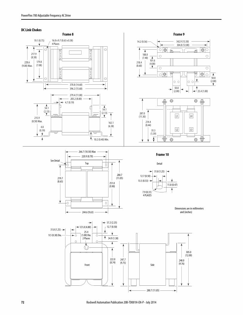
72 Rockwell Automation Publication 20B-TD001H-EN-P - July 2014
PowerFlex 700 Adjustable Frequency AC Drive
DC Link Chokes
12.7 (0.50)31.8 (1.25)
222.0(8.74)
25.4(1.00) Dia.
2 Places 34.9 (1.38)
57.2 (2.25)
121.8 (4.80)
9.5 (0.38) Dia.
251.0(9.90)
220.9 (8.70)
244.6 (9.63)
Top
Front Side
266.7 (10.50) Max
280.7(11.05)219.7
(8.65)
See Detail
280.7 (11.05)
248.0(9.76)
305.0(12.00)
247.7(9.75)
11.8 (0.47)
12.7 (0.50)
7.9 (0.31)4 PLACES
13.5 (0.53)
31.8 (1.25)
Detail
370.8 (14.60)
396.2 (15.60)
179.8
(7.08)
217.9
(8.58)
228.6
(9.00) Max.
19.1 (0.75) 16.0 x 9.7 (0.63 x 0.38)
4 Places
203.2 (8.00)
279.4 (11.00)
4.7 (0.19)
215.9
(8.50) Max.
4.8
(0.19)
54.1
(2.13)54.1
(2.13)
10.2 (0.40) Min.
162.1
(6.38)
Dimensions are in millimeters and (inches)
304.8 (12.00)
342.9 (13.50)14.2 (0.56)
287.0(11.30)
35.3(1.39)
214.4(8.44)
218.4(8.60)
188.0(7.40)
101.6(4.00)
L1
L2 L3
L4
25.4 (1.00)50.8
(2.00)
50.8(2.00)
Frame 8 Frame 9
Frame 10

Rockwell Automation Publication 20B-TD001H-EN-P - July 2014 73
PowerFlex 700 Adjustable Frequency AC Drive
Frame 10 – IP20, NEMA / UL Type 1AC Input Shown, for DC Input Dimensions use the Inverter (Left) Bay
Approx. Weight kg (lbs.)Type Drive Drive & PackagingDC Input 468 (1032) 515 (1135)
AC Input 867 (1912) 958 (2112)
890.8
(35.07)
2374.0
(93.46)
1268.7
(49.95)
761.3
(29.97)
507.4
(19.98)
Dimensions are in millimeters and (inches)

74 Rockwell Automation Publication 20B-TD001H-EN-P - July 2014
PowerFlex 700 Adjustable Frequency AC Drive
Frame 10 – IP00, NEMA / UL Type Open
Approx. Weight kg (lbs.)Type Drive Drive & PackagingDC Input 305 (672) 352 (775)
AC Input 532 (1172) 623 (1372)
120IN1
120IN2
3
4
5
6
DC+
DANGER
DANGER
DANGER
TB98 AMPERES RMS
MAXIMUM
120IN1
120IN2
3
4
5
6
V WU
TB11
PE25 AMPERES RMS
MAXIMUM
GND
RISK OF SHOCKREPLACE AFTER
SERVICING
! DANGER
RISK OF SHOCKREPLACE AFTER
SERVICING
! DANGER
RISK OF SHOCKREPLACE AFTER
SERVICING
! DANGER
TB108 AMPERES RMS
MAXIMUM
120IN1
120IN2
3
4
5
6
TB108 AMPERES RMS
MAXIMUM
GND
RISK OF SHOCKREPLACE AFTER
SERVICING
! DANGER
543.6(21.40)
591.8(23.30)
2275.8(89.60)
252.7(9.95)
473.4(18.64)
1267.8(49.91)
757.8(29.83)
503.7(19.83)
353.8(13.93)
445.8(17.55)
Dimensions are in millimeters and (inches)
AC Input Shown, for DC Input Dimensions use the Inverter (Left) Bay

Rockwell Automation Publication 20B-TD001H-EN-P - July 2014 75
PowerFlex 700 Adjustable Frequency AC Drive
Frame 10 – Flange Mount Cutout
IMPORTANT Backplate and extension are a single piece. Drive chassis can be removed from backplate to mount in user supplied IP54, NEMA / UL Type 12 enclosure.
553.3 (21.79)
355.6 (14.00)
152.4(6.00)
22.5(0.89)
52.1 (2.05)
279.4 (11.00)hole spacing,
5 places,both sides
254.0 (10.00)hole spacing
5 places, both sides
508.0 (20.00)
38.1(1.50)
152.4(6.00)
152.4(6.00)
32.3 (1.27)
39.9 (1.57)
7.6 (0.30)
1588.5(62.54)
Holes are for M6 self tapping screws.
381.0 (15.00)
See Detail
Inverter Converter
37.7(1.49)
66.5 (2.62)
22.9 (0.90)
58.6 (2.31)
12.7 (0.50)
1471.9(57.95)
22.9(0.90)
Dimensions are in millimeters and (inches)
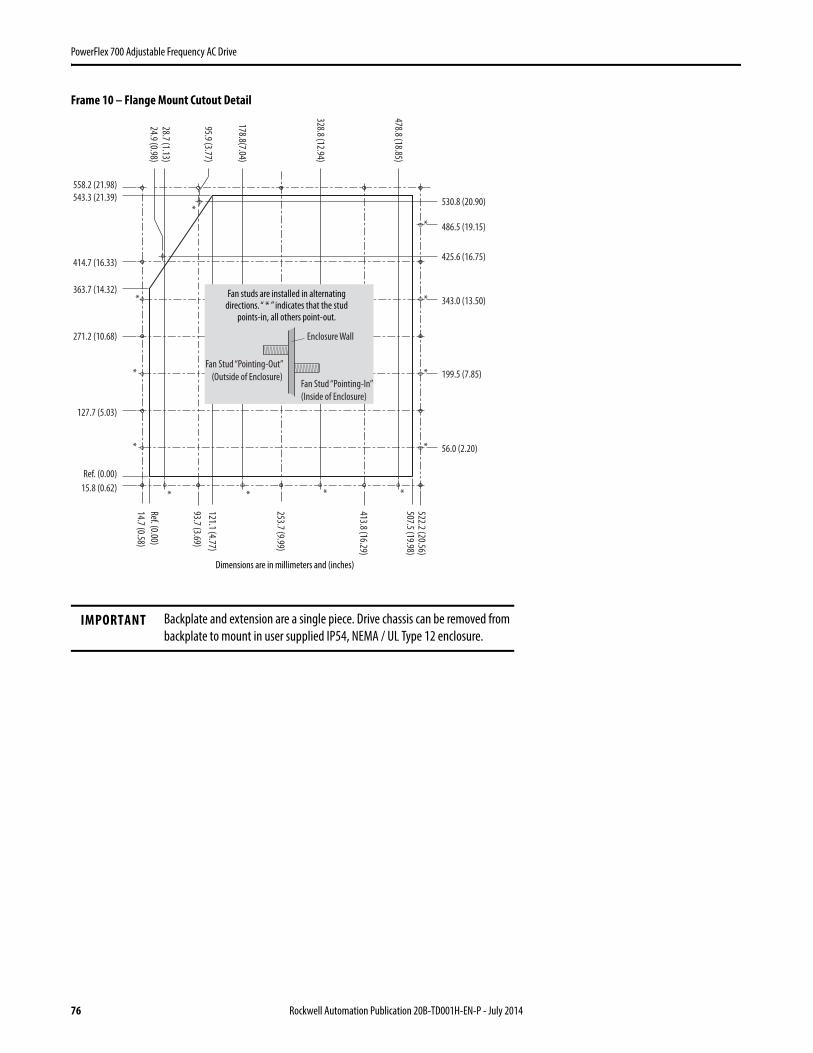
76 Rockwell Automation Publication 20B-TD001H-EN-P - July 2014
PowerFlex 700 Adjustable Frequency AC Drive
Frame 10 – Flange Mount Cutout Detail
IMPORTANT Backplate and extension are a single piece. Drive chassis can be removed from backplate to mount in user supplied IP54, NEMA / UL Type 12 enclosure.
56.0 (2.20)*
**
*
*
*
199.5 (7.85)
343.0 (13.50)
486.5 (19.15)
530.8 (20.90)
425.6 (16.75)
15.8 (0.62)
Ref. (0.00)
127.7 (5.03)
271.2 (10.68)
363.7 (14.32)
414.7 (16.33)
543.3 (21.39)
558.2 (21.98)
24.9 (0.98)
28.7 (1.13)
95.9 (3.77)
178.8(7.04)
328.8 (12.94)
478.8 (18.85)
14.7 (0.58)
Ref. (0.00)
93.7 (3.69)
121.1 (4.77)
253.7 (9.99)
413.8 (16.29)
507.5 (19.98)522.2 (20.56)
*
*
*
*
* *
Fan studs are installed in alternatingdirections. “ * ” indicates that the stud
points-in, all others point-out.
Enclosure Wall
Fan Stud “Pointing-In”
(Inside of Enclosure)
Fan Stud “Pointing-Out”
(Outside of Enclosure)
Dimensions are in millimeters and (inches)
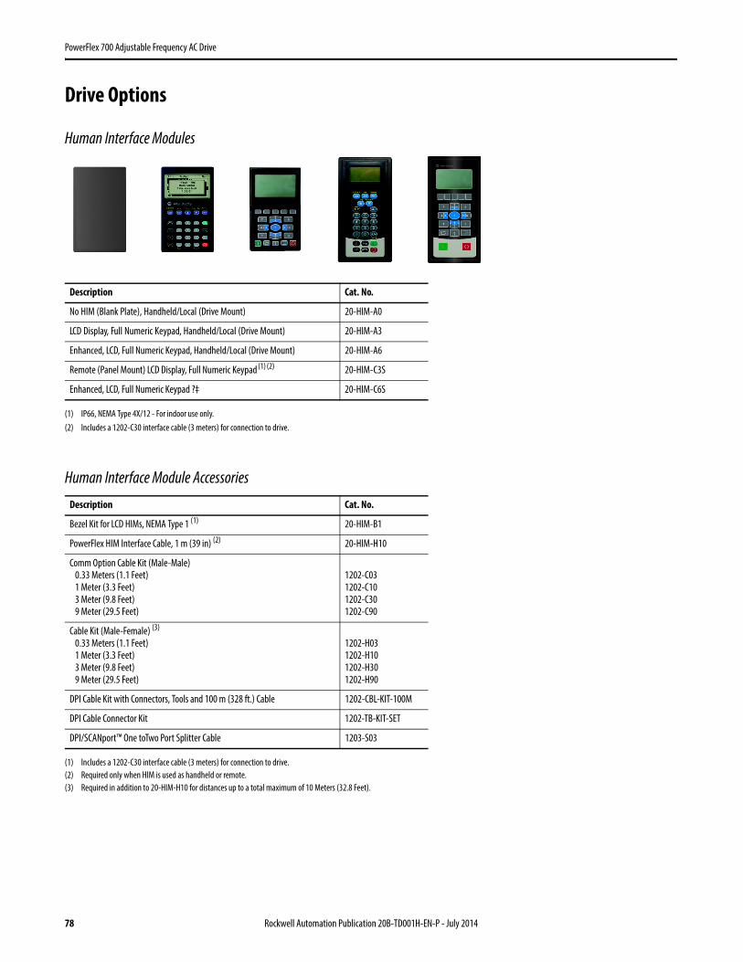
78 Rockwell Automation Publication 20B-TD001H-EN-P - July 2014
PowerFlex 700 Adjustable Frequency AC Drive
Drive Options
Human Interface Modules
Human Interface Module Accessories
Description Cat. No.
No HIM (Blank Plate), Handheld/Local (Drive Mount) 20-HIM-A0
LCD Display, Full Numeric Keypad, Handheld/Local (Drive Mount) 20-HIM-A3
Enhanced, LCD, Full Numeric Keypad, Handheld/Local (Drive Mount) 20-HIM-A6
Remote (Panel Mount) LCD Display, Full Numeric Keypad (1) (2)
(1) IP66, NEMA Type 4X/12 - For indoor use only.(2) Includes a 1202-C30 interface cable (3 meters) for connection to drive.
20-HIM-C3S
Enhanced, LCD, Full Numeric Keypad ?‡ 20-HIM-C6S
Description Cat. No.
Bezel Kit for LCD HIMs, NEMA Type 1 (1)
(1) Includes a 1202-C30 interface cable (3 meters) for connection to drive.
20-HIM-B1
PowerFlex HIM Interface Cable, 1 m (39 in) (2)
(2) Required only when HIM is used as handheld or remote.
20-HIM-H10
Comm Option Cable Kit (Male-Male)0.33 Meters (1.1 Feet)1 Meter (3.3 Feet)3 Meter (9.8 Feet)9 Meter (29.5 Feet)
1202-C031202-C101202-C301202-C90
Cable Kit (Male-Female) (3)
0.33 Meters (1.1 Feet)1 Meter (3.3 Feet)3 Meter (9.8 Feet)9 Meter (29.5 Feet)
(3) Required in addition to 20-HIM-H10 for distances up to a total maximum of 10 Meters (32.8 Feet).
1202-H031202-H101202-H301202-H90
DPI Cable Kit with Connectors, Tools and 100 m (328 ft.) Cable 1202-CBL-KIT-100M
DPI Cable Connector Kit 1202-TB-KIT-SET
DPI/SCANport™ One toTwo Port Splitter Cable 1203-S03
Rockwell Automation Publication 20B-TD001H-EN-P - July 2014 79
PowerFlex 700 Adjustable Frequency AC Drive
Communication Option Kits and Accessories
Feedback Options
Other Options
Description Cat. No.
BACnet® MS/TP RS485 Communication Adapter 20-COMM-B
ControlNet Communication Adapter (Coax) 20-COMM-C
DeviceNet Communication Adapter 20-COMM-D
EtherNet/IP™ Communication Adapter 20-COMM-E
Dual-port EtherNet/IP™ Communication Adapter 20-COMM-ER (2)
(2) Contact your local Rockwell Automation sales office or Allen-Bradley distributor for availability.
HVAC Communication Adapter (Only Modbus RTU can be used) 20-COMM-H
CANopen® Communication Adapter 20-COMM-K
LonWorks® Communication Adapter 20-COMM-L
Modbus/TCP Communication Adapter 20-COMM-M
PROFIBUS™ DP Communication Adapter 20-COMM-P
ControlNet Communication Adapter (Fiber) 20-COMM-Q
Remote I/O Communication Adapter 20-COMM-R (3)
(3) This item has Silver Series status. For information, refer to http://www.ab.com/silver.
RS485 DF1 Communication Adapter 20-COMM-S
External Communications Kit Power Supply 20-XCOMM-AC-PS1
DPI External Communications Kit 20-XCOMM-DC-BASE
External DPI I/O Option Board (1)
(1) For use only with DPI External Communications Kits 20-XCOMM-DC-BASE.
20-XCOMM-IO-OPT1
Compact I/O™ Module (3 Channel) 1769-SM1
Serial Null Modem Adapter 1203-SNM
Smart Self-powered Serial Converter (RS232) includes 1203-SFC and 1202-C10 Cables 1203-SSS
Universal Serial Bus™ (USB) Converter includes 2 m USB, 20-HIM-H10 & 22-HIM-H10 Cables 1203-USB
Description Cat. No.
12V/5V Encoder (1)
(1) Vector Control only.
20B-ENC-1
Description Cat. No.
Removable I/O Terminal Block SK-G9-TB1-S1
Removable Encoder Terminal Block SK-G9-TB1-ENC1

80 Rockwell Automation Publication 20B-TD001H-EN-P - July 2014
PowerFlex 700 Adjustable Frequency AC Drive
PowerFlex 700 Control Option Kits
Internal Dynamic Brake Resistor KitsThese resistors have a limited duty cycle. Refer to the PowerFlex Dynamic Braking Selection Guide to determine if an internal resistor will be sufficient for your application. An external resistor may be required.
Terminators
Reflected Wave Reduction Modules w/Common Mode Choke
Control with I/OFactory Installed Cat. Code # (2)
(2) This code is entered at the end of the drive catalog number (positions 17…20).
Cat. No.
Vector Control - 24V DC with: (1)
(1) Vector Control option utilizes DPI Only.
60 Hz Maximum NNAD 20B-VECT-C0AD
82 Hz Maximum NNAX 20B-VECTB-C0AX
Cascading Fan/Pump Control NNAE 20B-VECT-C0AE
Pump Off (for Pump Jack) NNBA 20B-VECTB-C0BA
Vector Control - 115V AC(1) D (3)
(3) This code is entered at position 15 of the drive catalog number.
20B-VECTB-D0
Vector Control - 115V AC with:(1)
60 Hz Maximum NNAD 20B-VECT-D0AD
82 Hz Maximum NNAX 20B-VECTB-D0AX
Cascading Fan/Pump Control NNAE 20B-VECT-D0AE
Pump Off (for Pump Jack) NNBA 20B-VECT-D0BA
Drive Input Voltage
Brake Resistance
Frame Cat. No.Ohms
208…240V AC 62 0 20BB-DB1-0
62 1 (except 7.5 Hp) 20BB-DB1-1
22 1 (7.5 Hp) 20BB-DB2-1
22 2 20BB-DB1-2
380…600V AC 115 0 20BD-DB1-0
115 1 20BD-DB1-1
68 2 20BD-DB1-2
Description (1)
(1) Refer to Appendix A of the Wiring and Grounding Guidelines for Pulse Width Modulated (PWM) AC Drives, publication Drives-IN001 for selection information.
Cat. No.
for use with 3.7 kW (5 Hp) & below drives 1204-TFA1
for use with 1.5 kW (2 Hp) & up drives 1204-TFB2
Description (1)
(1) Refer to Appendix A of the Wiring and Grounding Guidelines for Pulse Width Modulated (PWM) AC Drives, publication Drives-IN001 for selection information.
Cat. No.
17A with Common Mode Choke 1204-RWC-17-A

Rockwell Automation Publication 20B-TD001H-EN-P - July 2014 81
PowerFlex 700 Adjustable Frequency AC Drive
Isolation Transformers
For installations that have specific types of AC supply configurations or require drive protection due to AC line disturbances, isolation transformers are available.
IP32 (NEMA/UL Type 3R)
Motor RatingkW (Hp)
240V, 60 Hz, Three-Phase, 240V Primary & 240V Secondary
460V, 60 Hz, Three-Phase, 460V Primary & 460V Secondary
575V, 60 Hz, Three-Phase,575V Primary & 575V Secondary
Cat. No. Cat. No. Cat. No.
0.25 (0.33) 1321-3TW005-AA 1321-3TW005-BB –
0.37 (0.5) 1321-3TW005-AA 1321-3TW005-BB –
0.55 (0.75) 1321-3TW005-AA 1321-3TW005-BB –
0.75 (1.0) 1321-3TW005-AA 1321-3TW005-BB 1321-3TW005-CC
1.1 (1.5) 1321-3TW005-AA 1321-3TW005-BB –
1.5 (2.0) 1321-3TW005-AA 1321-3TW005-BB 1321-3TW005-CC
2.2 (3.0) 1321-3TW005-AA 1321-3TW005-BB 1321-3TW005-CC
4.0 (5.0) 1321-3TW007-AA 1321-3TW007-BB 1321-3TW007-CC
5.5 (7.5) 1321-3TW011-AA 1321-3TW011-BB 1321-3TW011-CC
7.5 (10) 1321-3TW014-AA 1321-3TW014-BB 1321-3TW014-CC
11 (15) 1321-3TW020-AA 1321-3TW020-BB 1321-3TW020-CC
15 (20) 1321-3TW027-AA 1321-3TW027-BB 1321-3TW027-CC
18.5 (25) 1321-3TW034-AA 1321-3TW034-BB 1321-3TW034-CC
22 (30) 1321-3TW040-AA 1321-3TW040-BB 1321-3TW040-CC
30 (40) 1321-3TW051-AA 1321-3TW051-BB 1321-3TW051-CC
37 (50) 1321-3TH063-AA 1321-3TH063-BB 1321-3TH063-CC
45 (60) 1321-3TH075-AA 1321-3TH075-BB 1321-3TH075-CC
55 (75) 1321-3TH093-AA 1321-3TH093-BB 1321-3TH093-CC
75 (100) – 1321-3TH118-BB 1321-3TH118-CC
90 (125) – 1321-3TH145-BB 1321-3TH145-CC
110 (150) – 1321-3TH175-BB 1321-3TH175-CC
149 (200) – 1321-3TH220-BB 1321-3TH220-CC
187 (250) – 1321-3TH275-BB 1321-3TH275-CC
224 (300) – 1321-3TH330-BB 1321-3TH330-CC
261 (350) – 1321-3TH440-BB 1321-3TH440-CC
298 (400) – 1321-3TH440-BB 1321-3TH440-CC
336 (450) – 1321-3TH550-BB 1321-3TH550-CC
373 (500) – 1321-3TH550-BB 1321-3TH550-CC
448 (600) – 1321-3TH660-BB 1321-3TH660-CC
485 (650) – – 1321-3TH770-CC
522 (700) – 1321-3TH770-BB 1321-3TH770-CC

82 Rockwell Automation Publication 20B-TD001H-EN-P - July 2014
PowerFlex 700 Adjustable Frequency AC Drive
Input/Output Line Reactors
For impedance matching, protection from AC line disturbances or motor protection, reactors are available for both the input and output sides of the drive.
240V, 60 Hz, Three-Phase, 3% Impedance
Drive Cat. No. Duty Hp
Input Line Reactor (1)
(1) Input line reactors were sized based on the NEC fundamental motor amps. Output line reactors were sized based on the VFD rated output currents.
Output Line Reactor (1)
IP00 (Open Style) IP11 (NEMA/UL Type 1) IP00 (Open Style) IP11 (NEMA/UL Type 1)
Cat. No. Cat. No. Cat. No. Cat. No.
20BB2P2 Heavy Duty 0.33 1321-3R2-D 1321-3RA2-D 1321-3R2-D 1321-3RA2-D
20BB2P2 Normal Duty 0.5 1321-3R2-D 1321-3RA2-D 1321-3R2-D 1321-3RA2-D
20BB4P2 Heavy Duty 0.75 1321-3R4-A 1321-3RA4-A 1321-3R4-A 1321-3RA4-A
20BB4P2 Normal Duty 1 1321-3R4-A 1321-3RA4-A 1321-3R4-A 1321-3RA4-A
20BB6P8 Heavy Duty 1.5 1321-3R8-B 1321-3RA8-B 1321-3R8-A 1321-3RA8-A
20BB6P8 Normal Duty 2 1321-3R8-A 1321-3RA8-A 1321-3R8-A 1321-3RA8-A
20BB9P6 Heavy Duty 2 1321-3R8-A 1321-3RA8-A 1321-3R12-A 1321-3RA12-A
20BB9P6 Normal Duty 3 1321-3R12-A 1321-3RA12-A 1321-3R12-A 1321-3RA12-A
20BB015 Heavy Duty 3 1321-3R12-A 1321-3RA12-A 1321-3R18-A 1321-3RA18-A
20BB015 Normal Duty 5 1321-3R18-A 1321-3RA18-A 1321-3R18-A 1321-3RA18-A
20BB022 Heavy Duty 5 1321-3R18-A 1321-3RA18-A 1321-3R25-A 1321-3RA25-A
20BB022 Normal Duty 7.5 1321-3R25-A 1321-3RA25-A 1321-3R25-A 1321-3RA25-A
20BB028 Heavy Duty 7.5 1321-3R25-A 1321-3RA25-A 1321-3R35-A 1321-3RA35-A
20BB028 Normal Duty 10 1321-3R35-A 1321-3RA35-A 1321-3R35-A 1321-3RA35-A
20BB042 Heavy Duty 10 1321-3R35-A 1321-3RA35-A 1321-3R45-A 1321-3RA45-A
20BB042 Normal Duty 15 1321-3R45-A 1321-3RA45-A 1321-3R45-A 1321-3RA45-A
20BB052 Heavy Duty 15 1321-3R45-A 1321-3RA45-A 1321-3R55-A 1321-3RA55-A
20BB052 Normal Duty 20 1321-3R55-A 1321-3RA55-A 1321-3R55-A 1321-3RA55-A
20BB070 Heavy Duty 20 1321-3R55-A 1321-3RA55-A 1321-3R80-A 1321-3RA80-A
20BB070 Normal Duty 25 1321-3R80-A 1321-3RA80-A 1321-3R80-A 1321-3RA80-A
20BB080 Heavy Duty 25 1321-3R80-A 1321-3RA80-A 1321-3R80-A 1321-3RA80-A
20BB080 Normal Duty 30 1321-3R80-A 1321-3RA80-A 1321-3R80-A 1321-3RA80-A
20BB104 Heavy Duty 30 1321-3R80-A 1321-3RA80-A 1321-3R80-A 1321-3RA80-A
20BB104 Normal Duty 40 1321-3R100-A 1321-3RA100-A 1321-3R100-A 1321-3RA100-A
20BB130 Heavy Duty 40 1321-3R100-A 1321-3RA100-A 1321-3R100-A 1321-3RA100-A
20BB130 Normal Duty 50 1321-3R130-A 1321-3RA130-A 1321-3R130-A 1321-3RA130-A
20BB154 Heavy Duty 50 1321-3R130-A 1321-3RA130-A 1321-3R130-A 1321-3RA130-A
20BB154 Normal Duty 60 1321-3R160-A 1321-3RA160-A 1321-3R160-A 1321-3RA160-A
20BB192 Heavy Duty 60 1321-3R160-A 1321-3RA160-A 1321-3R160-A 1321-3RA160-A
20BB192 Normal Duty 75 1321-3R200-A 1321-3RA200-A 1321-3R200-A 1321-3RA200-A
20BB260 Heavy Duty 75 1321-3R200-A 1321-3RA200-A 1321-3R200-A 1321-3RA200-A
20BB260 Normal Duty 100 1321-3RB250-A 1321-3RAB250-A 1321-3RB250-A 1321-3RAB250-A
Rockwell Automation Publication 20B-TD001H-EN-P - July 2014 83
PowerFlex 700 Adjustable Frequency AC Drive
240V, 60 Hz, Three-Phase, 5% Impedance
Drive Cat. No. Duty Hp
Input Line Reactor (1)
(1) Input line reactors were sized based on the NEC fundamental motor amps. Output line reactors were sized based on the VFD rated output currents.
Output Line Reactor (1)
IP00 (Open Style) IP11 (NEMA/UL Type 1) IP00 (Open Style) IP11 (NEMA/UL Type 1)
Cat. No. Cat. No. Cat. No. Cat. No.
20BB2P2 Heavy Duty 0.33 1321-3R2-A 1321-3RA2-A 1321-3R2-A 1321-3RA2-A
20BB2P2 Normal Duty 0.5 1321-3R2-A 1321-3RA2-A 1321-3R2-A 1321-3RA2-A
20BB4P2 Heavy Duty 0.75 1321-3R4-B 1321-3RA4-B 1321-3R4-B 1321-3RA4-B
20BB4P2 Normal Duty 1 1321-3R4-B 1321-3RA4-B 1321-3R4-B 1321-3RA4-B
20BB6P8 Heavy Duty 1.5 1321-3R8-B 1321-3RA8-B 1321-3R8-B 1321-3RA8-B
20BB6P8 Normal Duty 2 1321-3R8-B 1321-3RA8-B 1321-3R8-B 1321-3RA8-B
20BB9P6 Heavy Duty 2 1321-3R8-B 1321-3RA8-B 1321-3R12-B 1321-3RA12-B
20BB9P6 Normal Duty 3 1321-3R12-B 1321-3RA12-B 1321-3R12-B 1321-3RA12-B
20BB015 Heavy Duty 3 1321-3R12-B 1321-3RA12-B 1321-3R18-B 1321-3RA18-B
20BB015 Normal Duty 5 1321-3R18-B 1321-3RA18-B 1321-3R18-B 1321-3RA18-B
20BB022 Heavy Duty 5 1321-3R18-B 1321-3RA18-B 1321-3R25-B 1321-3RA25-B
20BB022 Normal Duty 7.5 1321-3R25-B 1321-3RA25-B 1321-3R25-B 1321-3RA25-B
20BB028 Heavy Duty 7.5 1321-3R25-B 1321-3RA25-B 1321-3R35-B 1321-3RA35-B
20BB028 Normal Duty 10 1321-3R35-B 1321-3RA35-B 1321-3R35-B 1321-3RA35-B
20BB042 Heavy Duty 10 1321-3R35-B 1321-3RA35-B 1321-3R45-B 1321-3RA45-B
20BB042 Normal Duty 15 1321-3R45-B 1321-3RA45-B 1321-3R45-B 1321-3RA45-B
20BB052 Heavy Duty 15 1321-3R45-B 1321-3RA45-B 1321-3R55-B 1321-3RA55-B
20BB052 Normal Duty 20 1321-3R55-B 1321-3RA55-B 1321-3R55-B 1321-3RA55-B
20BB070 Heavy Duty 20 1321-3R55-B 1321-3RA55-B 1321-3R80-B 1321-3RA80-B
20BB070 Normal Duty 25 1321-3R80-B 1321-3RA80-B 1321-3R80-B 1321-3RA80-B
20BB080 Heavy Duty 25 1321-3R80-B 1321-3RA80-B 1321-3R80-B 1321-3RA80-B
20BB080 Normal Duty 30 1321-3R80-B 1321-3RA80-B 1321-3R80-B 1321-3RA80-B
20BB104 Heavy Duty 30 1321-3R80-B 1321-3RA80-B 1321-3R80-B 1321-3RA80-B
20BB104 Normal Duty 40 1321-3R100-B 1321-3RA100-B 1321-3R100-B 1321-3RA100-B
20BB130 Heavy Duty 40 1321-3R100-B 1321-3RA100-B 1321-3R100-B 1321-3RA100-B
20BB130 Normal Duty 50 1321-3R130-B 1321-3RA130-B 1321-3R130-B 1321-3RA130-B
20BB154 Heavy Duty 50 1321-3R130-B 1321-3RA130-B 1321-3R130-B 1321-3RA130-B
20BB154 Normal Duty 60 1321-3R160-B 1321-3RA160-B 1321-3R160-B 1321-3RA160-B
20BB192 Heavy Duty 60 1321-3R160-B 1321-3RA160-B 1321-3R160-B 1321-3RA160-B
20BB192 Normal Duty 75 1321-3R200-B 1321-3RA200-B 1321-3R200-B 1321-3RA200-B
20BB260 Heavy Duty 75 1321-3R200-B 1321-3RA200-B 1321-3R200-B 1321-3RA200-B
20BB260 Normal Duty 100 1321-3RB250-B 1321-3RAB250-B 1321-3RB250-B 1321-3RAB250-B

84 Rockwell Automation Publication 20B-TD001H-EN-P - July 2014
PowerFlex 700 Adjustable Frequency AC Drive
480V, 60 Hz, Three-Phase, 3% Impedance
Drive Cat. No. Duty Hp
Input Line Reactor (1) Output Line Reactor (1)
IP00 (Open Style) IP11 (NEMA/UL Type 1) IP00 (Open Style) IP11 (NEMA/UL Type 1)
Cat. No. Cat. No. Cat. No. Cat. No.
20BD1P1 Heavy Duty 0.33 1321-3R1-C 1321-3RA1-C 1321-3R2-B 1321-3RA2-B
20BD1P1 Normal Duty 0.5 1321-3R1-C 1321-3RA1-C 1321-3R2-B 1321-3RA2-B
20BD2P1 Heavy Duty 0.75 1321-3R2-A 1321-3RA2-A 1321-3R2-A 1321-3RA2-A
20BD2P1 Normal Duty 1 1321-3R2-A 1321-3RA2-A 1321-3R2-A 1321-3RA2-A
20BD3P4 Heavy Duty 1.5 1321-3R4-C 1321-3RA4-C 1321-3R4-B 1321-3RA4-B
20BD3P4 Normal Duty 2 1321-3R4-B 1321-3RA4-B 1321-3R4-B 1321-3RA4-B
20BD5P0 Heavy Duty 2 1321-3R4-B 1321-3RA4-B 1321-3R8-C 1321-3RA8-C
20BD5P0 Normal Duty 3 1321-3R8-C 1321-3RA8-C 1321-3R8-C 1321-3RA8-C
20BD8P0 Heavy Duty 3 1321-3R8-C 1321-3RA8-C 1321-3R8-B 1321-3RA8-B
20BD8P0 Normal Duty 5 1321-3R8-B 1321-3RA8-B 1321-3R8-B 1321-3RA8-B
20BD011 Heavy Duty 5 1321-3R8-B 1321-3RA8-B 1321-3R12-B 1321-3RA12-B
20BD011 Normal Duty 7.5 1321-3R12-B 1321-3RA12-B 1321-3R12-B 1321-3RA12-B
20BD014 Heavy Duty 7.5 1321-3R12-B 1321-3RA12-B 1321-3R18-B 1321-3RA18-B
20BD014 Normal Duty 10 1321-3R18-B 1321-3RA18-B 1321-3R18-B 1321-3RA18-B
20BD022 Heavy Duty 10 1321-3R18-B 1321-3RA18-B 1321-3R25-B 1321-3RA25-B
20BD022 Normal Duty 15 1321-3R25-B 1321-3RA25-B 1321-3R25-B 1321-3RA25-B
20BD027 Heavy Duty 15 1321-3R25-B 1321-3RA25-B 1321-3R25-B 1321-3RA25-B
20BD027 Normal Duty 20 1321-3R35-B 1321-3RA35-B 1321-3R25-B 1321-3RA25-B
20BD034 Heavy Duty 20 1321-3R35-B 1321-3RA35-B 1321-3R35-B 1321-3RA35-B
20BD034 Normal Duty 25 1321-3R35-B 1321-3RA35-B 1321-3R35-B 1321-3RA35-B
20BD040 Heavy Duty 25 1321-3R35-B 1321-3RA35-B 1321-3R45-B 1321-3RA45-B
20BD040 Normal Duty 30 1321-3R45-B 1321-3RA45-B 1321-3R45-B 1321-3RA45-B
20BD052 Heavy Duty 30 1321-3R45-B 1321-3RA45-B 1321-3R55-B 1321-3RA55-B
20BD052 Normal Duty 40 1321-3R55-B 1321-3RA55-B 1321-3R55-B 1321-3RA55-B
20BD065 Heavy Duty 40 1321-3R55-B 1321-3RA55-B 1321-3R80-B 1321-3RA80-B
20BD065 Normal Duty 50 1321-3R80-B 1321-3RA80-B 1321-3R80-B 1321-3RA80-B
20BD077 Heavy Duty 50 1321-3R80-B 1321-3RA80-B 1321-3R80-B 1321-3RA80-B
20BD077 Normal Duty 60 1321-3R80-B 1321-3RA80-B 1321-3R80-B 1321-3RA80-B
20BD096 Heavy Duty 60 1321-3R80-B 1321-3RA80-B 1321-3R80-B 1321-3RA80-B
20BD096 Normal Duty 75 1321-3R100-B 1321-3RA100-B 1321-3R100-B 1321-3RA100-B
20BD125 Heavy Duty 75 1321-3R100-B 1321-3RA100-B 1321-3R100-B 1321-3RA100-B
20BD125 Normal Duty 100 1321-3R130-B 1321-3RA130-B 1321-3R130-B 1321-3RA130-B
20BD156 Heavy Duty 100 1321-3R130-B 1321-3RA130-B 1321-3R130-B 1321-3RA130-B
20BD156 Normal Duty 125 1321-3R160-B 1321-3RA160-B 1321-3R160-B 1321-3RA160-B
20BD180 Heavy Duty 125 1321-3R160-B 1321-3RA160-B 1321-3R160-B 1321-3RA160-B
20BD180 Normal Duty 150 1321-3R200-B 1321-3RA200-B 1321-3R200-C 1321-3RA200-C
continued
Rockwell Automation Publication 20B-TD001H-EN-P - July 2014 85
PowerFlex 700 Adjustable Frequency AC Drive
20BD248 Heavy Duty 150 1321-3R200-B 1321-3RA200-B 1321-3R200-C 1321-3RA200-C
20BD248 Normal Duty 200 1321-3RB250-B 1321-3RAB250-B 1321-3RB250-B 1321-3RAB250-B
20BD292 Heavy Duty 200 1321-3RB250-B 1321-3RAB250-B 1321-3RB250-B 1321-3RAB250-B
20BD292 Normal Duty 250 1321-3RB320-B 1321-3RAB320-B 1321-3RB320-B 1321-3RAB320-B
20BD325 Heavy Duty 250 1321-3RB320-B 1321-3RAB320-B 1321-3RB320-B 1321-3RAB320-B
20BD325 Normal Duty 250 1321-3RB320-B 1321-3RAB320-B 1321-3RB320-B 1321-3RAB320-B
20BD365 Heavy Duty 250 1321-3RB320-B 1321-3RAB320-B 1321-3RB320-B 1321-3RAB320-B
20BD365 Normal Duty 300 1321-3RB400-B 1321-3RAB400-B 1321-3RB400-B 1321-3RAB400-B
20BD415 Heavy Duty 300 1321-3RB400-B 1321-3RAB400-B 1321-3RB400-B 1321-3RAB400-B
20BD415 Normal Duty 350 1321-3RB400-B 1321-3RAB400-B 1321-3RB400-B 1321-3RAB400-B
20BD481 Heavy Duty 350 1321-3RB400-B 1321-3RAB400-B 1321-3RB400-B 1321-3RAB400-B
20BD481 Normal Duty 400 1321-3R500-B 1321-3RA500-B 1321-3R500-B 1321-3RA500-B
20BD535 Heavy Duty 400 1321-3R500-B 1321-3RA500-B 1321-3R500-B 1321-3RA500-B
20BD535 Normal Duty 450 1321-3R500-B 1321-3RA500-B 1321-3R500-B 1321-3RA500-B
20BD600 Heavy Duty 450 1321-3R500-B 1321-3RA500-B 1321-3R500-B 1321-3RA500-B
20BD600 Normal Duty 500 1321-3R600-B 1321-3RA600-B 1321-3R600-B 1321-3RA600-B
20BD730 Heavy Duty 500 1321-3R600-B 1321-3RA600-B 1321-3R600-B 1321-3RA600-B
20BD730 Normal Duty 600 1321-3R750-B 1321-3RA750-B 1321-3R750-B 1321-3RA750-B
20BD875 Heavy Duty 600 1321-3R750-B 1321-3RA750-B 1321-3R600-B 1321-3RA600-B
20BD875 Normal Duty 700 1321-3R850-B 1321-3RA850-B 1321-3R850-B 1321-3RA850-B
(1) Input line reactors were sized based on the NEC fundamental motor amps. Output line reactors were sized based on the VFD rated output currents.
Drive Cat. No. Duty Hp
Input Line Reactor (1) Output Line Reactor (1)
IP00 (Open Style) IP11 (NEMA/UL Type 1) IP00 (Open Style) IP11 (NEMA/UL Type 1)
Cat. No. Cat. No. Cat. No. Cat. No.
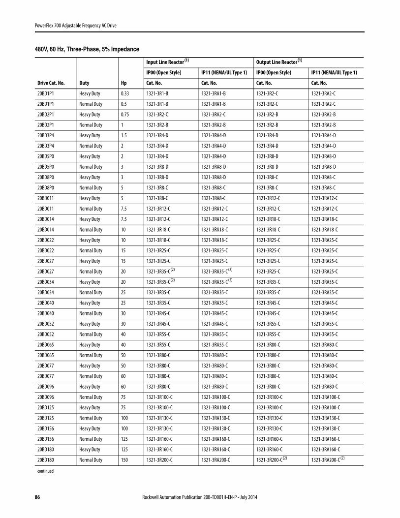
86 Rockwell Automation Publication 20B-TD001H-EN-P - July 2014
PowerFlex 700 Adjustable Frequency AC Drive
480V, 60 Hz, Three-Phase, 5% Impedance
Drive Cat. No. Duty Hp
Input Line Reactor (1) Output Line Reactor (1)
IP00 (Open Style) IP11 (NEMA/UL Type 1) IP00 (Open Style) IP11 (NEMA/UL Type 1)
Cat. No. Cat. No. Cat. No. Cat. No.
20BD1P1 Heavy Duty 0.33 1321-3R1-B 1321-3RA1-B 1321-3R2-C 1321-3RA2-C
20BD1P1 Normal Duty 0.5 1321-3R1-B 1321-3RA1-B 1321-3R2-C 1321-3RA2-C
20BD2P1 Heavy Duty 0.75 1321-3R2-C 1321-3RA2-C 1321-3R2-B 1321-3RA2-B
20BD2P1 Normal Duty 1 1321-3R2-B 1321-3RA2-B 1321-3R2-B 1321-3RA2-B
20BD3P4 Heavy Duty 1.5 1321-3R4-D 1321-3RA4-D 1321-3R4-D 1321-3RA4-D
20BD3P4 Normal Duty 2 1321-3R4-D 1321-3RA4-D 1321-3R4-D 1321-3RA4-D
20BD5P0 Heavy Duty 2 1321-3R4-D 1321-3RA4-D 1321-3R8-D 1321-3RA8-D
20BD5P0 Normal Duty 3 1321-3R8-D 1321-3RA8-D 1321-3R8-D 1321-3RA8-D
20BD8P0 Heavy Duty 3 1321-3R8-D 1321-3RA8-D 1321-3R8-C 1321-3RA8-C
20BD8P0 Normal Duty 5 1321-3R8-C 1321-3RA8-C 1321-3R8-C 1321-3RA8-C
20BD011 Heavy Duty 5 1321-3R8-C 1321-3RA8-C 1321-3R12-C 1321-3RA12-C
20BD011 Normal Duty 7.5 1321-3R12-C 1321-3RA12-C 1321-3R12-C 1321-3RA12-C
20BD014 Heavy Duty 7.5 1321-3R12-C 1321-3RA12-C 1321-3R18-C 1321-3RA18-C
20BD014 Normal Duty 10 1321-3R18-C 1321-3RA18-C 1321-3R18-C 1321-3RA18-C
20BD022 Heavy Duty 10 1321-3R18-C 1321-3RA18-C 1321-3R25-C 1321-3RA25-C
20BD022 Normal Duty 15 1321-3R25-C 1321-3RA25-C 1321-3R25-C 1321-3RA25-C
20BD027 Heavy Duty 15 1321-3R25-C 1321-3RA25-C 1321-3R25-C 1321-3RA25-C
20BD027 Normal Duty 20 1321-3R35-C (2) 1321-3RA35-C (2) 1321-3R25-C 1321-3RA25-C
20BD034 Heavy Duty 20 1321-3R35-C (2) 1321-3RA35-C (2) 1321-3R35-C 1321-3RA35-C
20BD034 Normal Duty 25 1321-3R35-C 1321-3RA35-C 1321-3R35-C 1321-3RA35-C
20BD040 Heavy Duty 25 1321-3R35-C 1321-3RA35-C 1321-3R45-C 1321-3RA45-C
20BD040 Normal Duty 30 1321-3R45-C 1321-3RA45-C 1321-3R45-C 1321-3RA45-C
20BD052 Heavy Duty 30 1321-3R45-C 1321-3RA45-C 1321-3R55-C 1321-3RA55-C
20BD052 Normal Duty 40 1321-3R55-C 1321-3RA55-C 1321-3R55-C 1321-3RA55-C
20BD065 Heavy Duty 40 1321-3R55-C 1321-3RA55-C 1321-3R80-C 1321-3RA80-C
20BD065 Normal Duty 50 1321-3R80-C 1321-3RA80-C 1321-3R80-C 1321-3RA80-C
20BD077 Heavy Duty 50 1321-3R80-C 1321-3RA80-C 1321-3R80-C 1321-3RA80-C
20BD077 Normal Duty 60 1321-3R80-C 1321-3RA80-C 1321-3R80-C 1321-3RA80-C
20BD096 Heavy Duty 60 1321-3R80-C 1321-3RA80-C 1321-3R80-C 1321-3RA80-C
20BD096 Normal Duty 75 1321-3R100-C 1321-3RA100-C 1321-3R100-C 1321-3RA100-C
20BD125 Heavy Duty 75 1321-3R100-C 1321-3RA100-C 1321-3R100-C 1321-3RA100-C
20BD125 Normal Duty 100 1321-3R130-C 1321-3RA130-C 1321-3R130-C 1321-3RA130-C
20BD156 Heavy Duty 100 1321-3R130-C 1321-3RA130-C 1321-3R130-C 1321-3RA130-C
20BD156 Normal Duty 125 1321-3R160-C 1321-3RA160-C 1321-3R160-C 1321-3RA160-C
20BD180 Heavy Duty 125 1321-3R160-C 1321-3RA160-C 1321-3R160-C 1321-3RA160-C
20BD180 Normal Duty 150 1321-3R200-C 1321-3RA200-C 1321-3R200-C (2) 1321-3RA200-C (2)
continued

Rockwell Automation Publication 20B-TD001H-EN-P - July 2014 87
PowerFlex 700 Adjustable Frequency AC Drive
20BD248 Heavy Duty 150 1321-3R200-C 1321-3RA200-C 1321-3R200-C (2) 1321-3RA200-C (2)
20BD248 Normal Duty 200 1321-3RB250-C 1321-3RAB250-C 1321-3RB250-C 1321-3RAB250-C
20BD292 Heavy Duty 200 1321-3RB250-C 1321-3RAB250-C 1321-3RB250-C 1321-3RAB250-C
20BD292 Normal Duty 250 1321-3RB320-C 1321-3RAB320-C 1321-3RB320-C 1321-3RAB320-C
20BD325 Heavy Duty 250 1321-3RB320-C 1321-3RAB320-C 1321-3RB320-C 1321-3RAB320-C
20BD325 Normal Duty 250 1321-3RB320-C 1321-3RAB320-C 1321-3RB320-C 1321-3RAB320-C
20BD365 Heavy Duty 250 1321-3RB320-C 1321-3RAB320-C 1321-3RB320-C 1321-3RAB320-C
20BD365 Normal Duty 300 1321-3RB400-C 1321-3RAB400-C 1321-3RB400-C 1321-3RAB400-C
20BD415 Heavy Duty 300 1321-3RB400-C 1321-3RAB400-C 1321-3RB400-C 1321-3RAB400-C
20BD415 Normal Duty 350 1321-3R500-C 1321-3RA500-C 1321-3RB400-C 1321-3RAB400-C
20BD481 Heavy Duty 350 1321-3R500-C 1321-3RA500-C 1321-3RB400-C 1321-3RAB400-C
20BD481 Normal Duty 400 1321-3R500-C 1321-3RA500-C 1321-3R500-C 1321-3RA500-C
20BD535 Heavy Duty 400 1321-3R500-C 1321-3RA500-C 1321-3R500-C 1321-3RA500-C
20BD535 Normal Duty 450 1321-3R600-C 1321-3RA600-C 1321-3R500-C 1321-3RA500-C
20BD600 Heavy Duty 450 1321-3R600-C 1321-3RA600-C 1321-3R500-C 1321-3RA500-C
20BD600 Normal Duty 500 1321-3R600-C 1321-3RA600-C 1321-3R600-C 1321-3RA600-C
20BD730 Heavy Duty 500 1321-3R600-C 1321-3RA600-C 1321-3R600-C 1321-3RA600-C
20BD730 Normal Duty 600 1321-3R750-E 1321-3RA750-E 1321-3R750-E 1321-3RA750-E
20BD875 Heavy Duty 600 1321-3R750-E 1321-3RA750-E 1321-3R750-E 1321-3RA750-E
20BD875 Normal Duty 700 1321-3R850-C 1321-3RA850-C 1321-3R850-C 1321-3RA850-C
(1) Input line reactors were sized based on the NEC fundamental motor amps. Output line reactors were sized based on the VFD rated output currents. (2) 4% impedance.
Drive Cat. No. Duty Hp
Input Line Reactor (1) Output Line Reactor (1)
IP00 (Open Style) IP11 (NEMA/UL Type 1) IP00 (Open Style) IP11 (NEMA/UL Type 1)
Cat. No. Cat. No. Cat. No. Cat. No.

88 Rockwell Automation Publication 20B-TD001H-EN-P - July 2014
PowerFlex 700 Adjustable Frequency AC Drive
600V, 60 Hz, Three-Phase, 3% Impedance
Drive Cat. No. Duty Hp
Input Line Reactor (1)
(1) Input line reactors were sized based on the NEC fundamental motor amps. Output line reactors were sized based on the VFD rated output currents.
Output Line Reactor (1)
IP00 (Open Style) IP11 (NEMA/UL Type 1) IP00 (Open Style) IP11 (NEMA/UL Type 1)
Cat. No. Cat. No. Cat. No. Cat. No.
20BE1P7 Heavy Duty 0.5 1321-3R1-C 1321-3RA1-C 1321-3R2-B 1321-3RA2-B
20BE1P7 Normal Duty 1 1321-3R2-B 1321-3RA2-B 1321-3R2-B 1321-3RA2-B
20BE2P7 Heavy Duty 1 1321-3R2-B 1321-3RA2-B 1321-3R4-D 1321-3RA4-D
20BE2P7 Normal Duty 2 1321-3R4-D 1321-3RA4-D 1321-3R4-D 1321-3RA4-D
20BE3P9 Heavy Duty 2 1321-3R4-D 1321-3RA4-D 1321-3R4-C 1321-3RA4-C
20BE3P9 Normal Duty 3 1321-3R4-C 1321-3RA4-C 1321-3R4-C 1321-3RA4-C
20BE6P1 Heavy Duty 3 1321-3R4-C 1321-3RA4-C 1321-3R8-C 1321-3RA8-C
20BE6P1 Normal Duty 5 1321-3R8-C 1321-3RA8-C 1321-3R8-C 1321-3RA8-C
20BE9P0 Heavy Duty 5 1321-3R8-C 1321-3RA8-C 1321-3R12-C 1321-3RA12-C
20BE9P0 Normal Duty 7.5 1321-3R12-C 1321-3RA12-C 1321-3R12-C 1321-3RA12-C
20BE011 Heavy Duty 7.5 1321-3R12-C 1321-3RA12-C 1321-3R12-B 1321-3RA12-B
20BE011 Normal Duty 10 1321-3R12-B 1321-3RA12-B 1321-3R12-B 1321-3RA12-B
20BE017 Heavy Duty 10 1321-3R12-B 1321-3RA12-B 1321-3R18-B 1321-3RA18-B
20BE017 Normal Duty 15 1321-3R18-B 1321-3RA18-B 1321-3R18-B 1321-3RA18-B
20BE022 Heavy Duty 15 1321-3R18-B 1321-3RA18-B 1321-3R25-B 1321-3RA25-B
20BE022 Normal Duty 20 1321-3R25-B 1321-3RA25-B 1321-3R25-B 1321-3RA25-B
20BE027 Heavy Duty 20 1321-3R25-B 1321-3RA25-B 1321-3R35-C 1321-3RA35-C
20BE027 Normal Duty 25 1321-3R35-C 1321-3RA35-C 1321-3R35-C 1321-3RA35-C
20BE032 Heavy Duty 25 1321-3R35-C 1321-3RA35-C 1321-3R35-B 1321-3RA35-B
20BE032 Normal Duty 30 1321-3R35-B 1321-3RA35-B 1321-3R35-B 1321-3RA35-B
20BE041 Heavy Duty 30 1321-3R35-B 1321-3RA35-B 1321-3R45-B 1321-3RA45-B
20BE041 Normal Duty 40 1321-3R45-B 1321-3RA45-B 1321-3R45-B 1321-3RA45-B
20BE052 Heavy Duty 40 1321-3R45-B 1321-3RA45-B 1321-3R55-B 1321-3RA55-B
20BE052 Normal Duty 50 1321-3R55-B 1321-3RA55-B 1321-3R55-B 1321-3RA55-B
20BE062 Heavy Duty 50 1321-3R55-B 1321-3RA55-B 1321-3R80-B 1321-3RA80-B
20BE062 Normal Duty 60 1321-3R80-B 1321-3RA80-B 1321-3R80-B 1321-3RA80-B
20BE077 Heavy Duty 60 1321-3R80-B 1321-3RA80-B 1321-3R80-B 1321-3RA80-B
20BE077 Normal Duty 75 1321-3R80-B 1321-3RA80-B 1321-3R80-B 1321-3RA80-B
20BE099 Heavy Duty 75 1321-3R80-B 1321-3RA80-B 1321-3R80-B 1321-3RA80-B
20BE099 Normal Duty 100 1321-3R100-B 1321-3RA100-B 1321-3R100-B 1321-3RA100-B
20BE125 Heavy Duty 100 1321-3R100-B 1321-3RA100-B 1321-3R100-B 1321-3RA100-B
20BE125 Normal Duty 125 1321-3R130-B 1321-3RA130-B 1321-3R130-B 1321-3RA130-B
20BE144 Heavy Duty 125 1321-3R130-B 1321-3RA130-B 1321-3R130-B 1321-3RA130-B
20BE144 Normal Duty 150 1321-3R160-B 1321-3RA160-B 1321-3R160-B 1321-3RA160-B
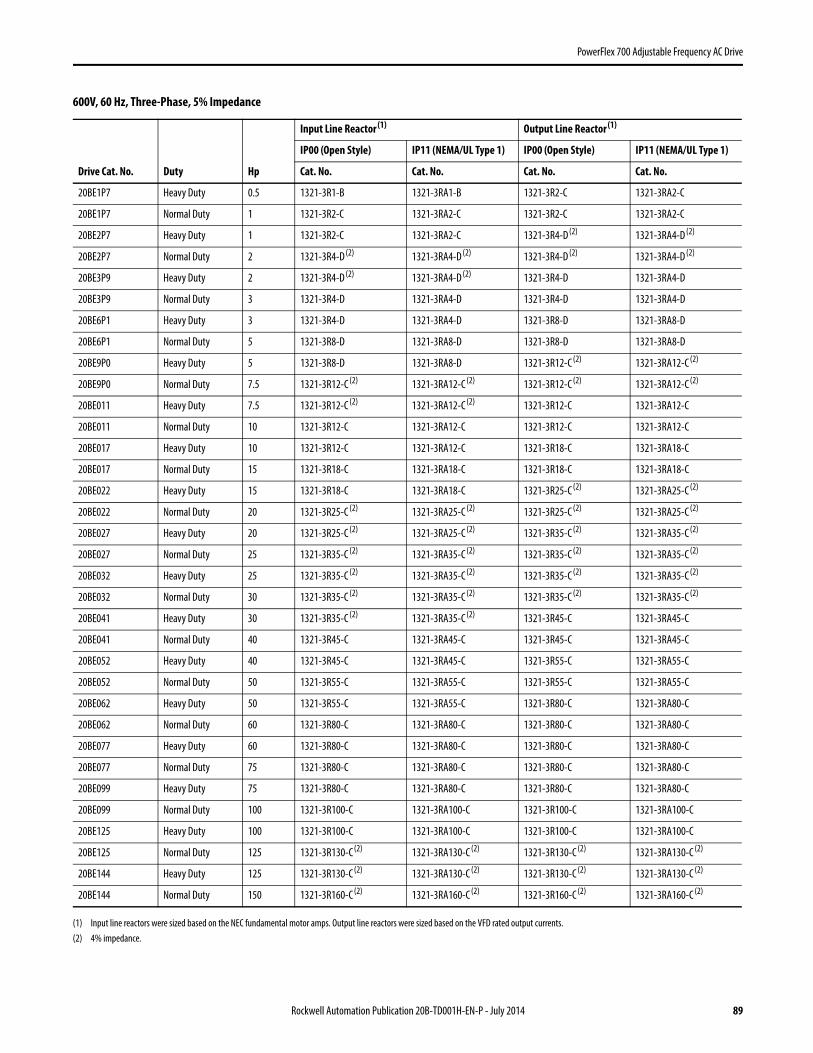
Rockwell Automation Publication 20B-TD001H-EN-P - July 2014 89
PowerFlex 700 Adjustable Frequency AC Drive
600V, 60 Hz, Three-Phase, 5% Impedance
Drive Cat. No. Duty Hp
Input Line Reactor (1)
(1) Input line reactors were sized based on the NEC fundamental motor amps. Output line reactors were sized based on the VFD rated output currents.
Output Line Reactor (1)
IP00 (Open Style) IP11 (NEMA/UL Type 1) IP00 (Open Style) IP11 (NEMA/UL Type 1)
Cat. No. Cat. No. Cat. No. Cat. No.
20BE1P7 Heavy Duty 0.5 1321-3R1-B 1321-3RA1-B 1321-3R2-C 1321-3RA2-C
20BE1P7 Normal Duty 1 1321-3R2-C 1321-3RA2-C 1321-3R2-C 1321-3RA2-C
20BE2P7 Heavy Duty 1 1321-3R2-C 1321-3RA2-C 1321-3R4-D (2) 1321-3RA4-D (2)
20BE2P7 Normal Duty 2 1321-3R4-D (2) 1321-3RA4-D (2) 1321-3R4-D (2) 1321-3RA4-D (2)
20BE3P9 Heavy Duty 2 1321-3R4-D (2) 1321-3RA4-D (2) 1321-3R4-D 1321-3RA4-D
20BE3P9 Normal Duty 3 1321-3R4-D 1321-3RA4-D 1321-3R4-D 1321-3RA4-D
20BE6P1 Heavy Duty 3 1321-3R4-D 1321-3RA4-D 1321-3R8-D 1321-3RA8-D
20BE6P1 Normal Duty 5 1321-3R8-D 1321-3RA8-D 1321-3R8-D 1321-3RA8-D
20BE9P0 Heavy Duty 5 1321-3R8-D 1321-3RA8-D 1321-3R12-C (2) 1321-3RA12-C (2)
20BE9P0 Normal Duty 7.5 1321-3R12-C (2)
(2) 4% impedance.
1321-3RA12-C (2) 1321-3R12-C (2) 1321-3RA12-C (2)
20BE011 Heavy Duty 7.5 1321-3R12-C (2) 1321-3RA12-C (2) 1321-3R12-C 1321-3RA12-C
20BE011 Normal Duty 10 1321-3R12-C 1321-3RA12-C 1321-3R12-C 1321-3RA12-C
20BE017 Heavy Duty 10 1321-3R12-C 1321-3RA12-C 1321-3R18-C 1321-3RA18-C
20BE017 Normal Duty 15 1321-3R18-C 1321-3RA18-C 1321-3R18-C 1321-3RA18-C
20BE022 Heavy Duty 15 1321-3R18-C 1321-3RA18-C 1321-3R25-C (2) 1321-3RA25-C (2)
20BE022 Normal Duty 20 1321-3R25-C (2) 1321-3RA25-C (2) 1321-3R25-C (2) 1321-3RA25-C (2)
20BE027 Heavy Duty 20 1321-3R25-C (2) 1321-3RA25-C (2) 1321-3R35-C (2) 1321-3RA35-C (2)
20BE027 Normal Duty 25 1321-3R35-C (2) 1321-3RA35-C (2) 1321-3R35-C (2) 1321-3RA35-C (2)
20BE032 Heavy Duty 25 1321-3R35-C (2) 1321-3RA35-C (2) 1321-3R35-C (2) 1321-3RA35-C (2)
20BE032 Normal Duty 30 1321-3R35-C (2) 1321-3RA35-C (2) 1321-3R35-C (2) 1321-3RA35-C (2)
20BE041 Heavy Duty 30 1321-3R35-C (2) 1321-3RA35-C (2) 1321-3R45-C 1321-3RA45-C
20BE041 Normal Duty 40 1321-3R45-C 1321-3RA45-C 1321-3R45-C 1321-3RA45-C
20BE052 Heavy Duty 40 1321-3R45-C 1321-3RA45-C 1321-3R55-C 1321-3RA55-C
20BE052 Normal Duty 50 1321-3R55-C 1321-3RA55-C 1321-3R55-C 1321-3RA55-C
20BE062 Heavy Duty 50 1321-3R55-C 1321-3RA55-C 1321-3R80-C 1321-3RA80-C
20BE062 Normal Duty 60 1321-3R80-C 1321-3RA80-C 1321-3R80-C 1321-3RA80-C
20BE077 Heavy Duty 60 1321-3R80-C 1321-3RA80-C 1321-3R80-C 1321-3RA80-C
20BE077 Normal Duty 75 1321-3R80-C 1321-3RA80-C 1321-3R80-C 1321-3RA80-C
20BE099 Heavy Duty 75 1321-3R80-C 1321-3RA80-C 1321-3R80-C 1321-3RA80-C
20BE099 Normal Duty 100 1321-3R100-C 1321-3RA100-C 1321-3R100-C 1321-3RA100-C
20BE125 Heavy Duty 100 1321-3R100-C 1321-3RA100-C 1321-3R100-C 1321-3RA100-C
20BE125 Normal Duty 125 1321-3R130-C (2) 1321-3RA130-C (2) 1321-3R130-C (2) 1321-3RA130-C (2)
20BE144 Heavy Duty 125 1321-3R130-C (2) 1321-3RA130-C (2) 1321-3R130-C (2) 1321-3RA130-C (2)
20BE144 Normal Duty 150 1321-3R160-C (2) 1321-3RA160-C (2) 1321-3R160-C (2) 1321-3RA160-C (2)