Embed Size (px)
Citation preview

Be sure this information reaches the operator.You can get extra copies through your supplier.
POWERCUT-1500PLASMA ARC CUTTING PACKAGE
F15-695-C 10 / 2003
2
These INSTRUCTIONS are for experienced operators. If you are not fully familiar with the principlesof operation and safe practices for arc welding and cutting equipment, we urge you to read our booklet,"Precautions and Safe Practices for Arc Welding, Cutting, and Gouging," Form 52-529. Do NOT permituntrained persons to install, operate, or maintain this equipment. Do NOT attempt to install or operatethis equipment until you have read and fully understand these instructions. If you do not fullyunderstand these instructions, contact your supplier for further information. Be sure to read theSafety Precautions before installing or operating this equipment.
USER RESPONSIBILITY
This equipment will perform in conformity with the description thereof contained in this manual and accompanyinglabels and/or inserts when installed, operated, maintained and repaired in accordance with the instructionsprovided. This equipment must be checked periodically. Malfunctioning or poorly maintained equipment shouldnot be used. Parts that are broken, missing, worn, distorted or contaminated should be replaced immediately.Should such repair or replacement become necessary, the manufacturer recommends that a telephone or writtenrequest for service advice be made to the Authorized Distributor from whom it was purchased.
This equipment or any of its parts should not be altered without the prior written approval of the manufacturer.The user of this equipment shall have the sole responsibility for any malfunction which results from improper use,faulty maintenance, damage, improper repair or alteration by anyone other than the manufacturer or a servicefacility designated by the manufacturer.
BE SURE THIS INFORMATION REACHES THE OPERATOR.YOU CAN GET EXTRA COPIES THROUGH YOUR SUPPLIER.

3
USER RESPONSIBILITY
This equipment will perform in conformity with the description thereof contained in this manual and accompanyinglabels and/or inserts when installed, operated, maintained and repaired in accordance with the instructions pro-vided. This equipment must be checked periodically. Malfunctioning or poorly maintained equipment should notbe used. Parts that are broken, missing, worn, distorted or contaminated should be replaced immediately. Shouldsuch repair or replacement become necessary, the manufacturer recommends that a telephone or written requestfor service advice be made to the Authorized Distributor from whom it was purchased.
This equipment or any of its parts should not be altered without the prior written approval of the manufacturer. Theuser of this equipment shall have the sole responsibility for any malfunction which results from improper use, faultymaintenance, damage, improper repair or alteration by anyone other than the manufacturer or a service facilitydesignated by the manufacturer.
TABLE OF CONTENTS
SECTION TITLE PAGEPARAGRAPH
SECTION 1 DESCRIPTION ................................................................................................. 101.1 General ............................................................................................................. 101.2 Scope ................................................................................................................ 101.3 Packages Available ........................................................................................... 101.4 Specifications .................................................................................................... 10
SECTION 2 INSTALLATION ................................................................................................ 132.1 General ............................................................................................................. 132.2 Equipment Required ......................................................................................... 132.3 Location ............................................................................................................ 132.4 Inspection .......................................................................................................... 132.5 Primary Electrical Input Connections ................................................................. 132.6 Secondary Output Connections ......................................................................... 15
SECTION 3 OPERATION ..................................................................................................... 163.1 Operation .......................................................................................................... 163.2 PowerCut-1500 Controls ................................................................................... 163.3 Cutting with the PT-32 ....................................................................................... 183.4 Possible Cutting Issues ..................................................................................... 21
SECTION 4 MAINTENANCE................................................................................................ 224,1 General ............................................................................................................. 224.2 Inspection and Cleaning .................................................................................... 224.3 PT-32 Torch Consumable Parts ........................................................................ 224.4 IGBT Handling & Replacement ......................................................................... 24
SECTION 5 TROUBLESHOOTING ..................................................................................... 265.1 Troubleshooting ................................................................................................ 265.2 Troubleshooting Guide ...................................................................................... 27
SECTION 6 REPLACEMENT PARTS .................................................................................. 36

4
WARNING: These Safety Precautions are foryour protection. They summarize precaution-ary information from the references listed inAdditional Safety Information section. Before
performing any installation or operating procedures, be sureto read and follow the safety precautions listed below as wellas all other manuals, material safety data sheets, labels,etc. Failure to observe Safety Precautions can result ininjury or death.
PROTECT YOURSELF AND OTHERS --Some welding, cutting, and gougingprocesses are noisy and require earprotection. The arc, like the sun, emitsultraviolet (UV) and other radiation and
can injure skin and eyes. Hot metal can cause burns.Training in the proper use of the processes and equip-ment is essential to prevent accidents. Therefore:
1. Always wear safety glasses with side shields in any workarea, even if welding helmets, face shields, and gogglesare also required.
2. Use a face shield fitted with the correct filter and coverplates to protect your eyes, face, neck, and ears fromsparks and rays of the arc when operating or observingoperations. Warn bystanders not to watch the arc and notto expose themselves to the rays of the electric-arc or hotmetal.
3. Wear flameproof gauntlet type gloves, heavy long-sleeveshirt, cuffless trousers, high-topped shoes, and a weld-ing helmet or cap for hair protection, to protect againstarc rays and hot sparks or hot metal. A flameproof apronmay also be desirable as protection against radiated heatand sparks.
4. Hot sparks or metal can lodge in rolled up sleeves,trouser cuffs, or pockets. Sleeves and collars should bekept buttoned, and open pockets eliminated from thefront of clothing
5. Protect other personnel from arc rays and hot sparks witha suitable non-flammable partition or curtains.
6. Use goggles over safety glasses when chipping slag orgrinding. Chipped slag may be hot and can fly far.Bystanders should also wear goggles over safety glasses.
FIRES AND EXPLOSIONS -- Heat fromflames and arcs can start fires. Hot slagor sparks can also cause fires and ex-plosions. Therefore:
1. Remove all combustible materials well away from thework area or cover the materials with a protective non-flammable covering. Combustible materials include wood,cloth, sawdust, liquid and gas fuels, solvents, paints andcoatings, paper, etc.
2. Hot sparks or hot metal can fall through cracks orcrevices in floors or wall openings and cause a hiddensmoldering fire or fires on the floor below. Make certainthat such openings are protected from hot sparks andmetal.“
3. Do not weld, cut or perform other hot work until theworkpiece has been completely cleaned so that there areno substances on the workpiece which might produceflammable or toxic vapors. Do not do hot work on closedcontainers. They may explode.
4. Have fire extinguishing equipment handy for instant use,such as a garden hose, water pail, sand bucket, orportable fire extinguisher. Be sure you are trained in itsuse.
10/2001
5. Do not use equipment beyond its ratings. For example,overloaded welding cable can overheat and create a firehazard.
6. After completing operations, inspect the work area tomake certain there are no hot sparks or hot metal whichcould cause a later fire. Use fire watchers when necessary.
7. For additional information, refer to NFPA Standard 51B,"Fire Prevention in Use of Cutting and Welding Pro-cesses", available from the National Fire Protection Asso-ciation, Batterymarch Park, Quincy, MA 02269.
ELECTRICAL SHOCK -- Contact with liveelectrical parts and ground can causesevere injury or death. DO NOT use ACwelding current in damp areas, if move-ment is confined, or if there is danger offalling.
1. Be sure the power source frame (chassis) is connectedto the ground system of the input power.
2. Connect the workpiece to a good electrical ground.3. Connect the work cable to the workpiece. A poor or
missing connection can expose you or others to a fatalshock.
4. Use well-maintained equipment. Replace worn or dam-aged cables.
5. Keep everything dry, including clothing, work area, cables,torch/electrode holder, and power source.
6. Make sure that all parts of your body are insulated fromwork and from ground.
7. Do not stand directly on metal or the earth while workingin tight quarters or a damp area; stand on dry boards oran insulating platform and wear rubber-soled shoes.
8. Put on dry, hole-free gloves before turning on the power.9. Turn off the power before removing your gloves.
10. Refer to ANSI/ASC Standard Z49.1 (listed on next page)for specific grounding recommendations. Do not mistakethe work lead for a ground cable.
ELECTRIC AND MAGNETIC FIELDS —May be dangerous. Electric current flow-ing through any conductor causes lo-calized Electric and Magnetic Fields(EMF). Welding and cutting current cre-ates EMF around welding cables andwelding machines. Therefore:
1. Welders having pacemakers should consult their physi-cian before welding. EMF may interfere with some pace-makers.
2. Exposure to EMF may have other health effects which areunknown.
3. Welders should use the following procedures to minimizeexposure to EMF:A. Route the electrode and work cables together. Secure
them with tape when possible.B. Never coil the torch or work cable around your body.C. Do not place your body between the torch and work
cables. Route cables on the same side of your body.D. Connect the work cable to the workpiece as close as
possible to the area being welded.E. Keep welding power source and cables as far away
from your body as possible.
SECTION 1 SAFETY PRECAUTIONS

5
FUMES AND GASES -- Fumes andgases, can cause discomfort or harm,particularly in confined spaces. Donot breathe fumes and gases. Shield-ing gases can cause asphyxiation.Therefore:
1. Always provide adequate ventilation in the work area bynatural or mechanical means. Do not weld, cut, or gougeon materials such as galvanized steel, stainless steel,copper, zinc, lead, beryllium, or cadmium unless positivemechanical ventilation is provided. Do not breathe fumesfrom these materials.
2. Do not operate near degreasing and spraying opera-tions. The heat or arc rays can react with chlorinatedhydrocarbon vapors to form phosgene, a highly toxicgas, and other irritant gases.
3. If you develop momentary eye, nose, or throat irritationwhile operating, this is an indication that ventilation is notadequate. Stop work and take necessary steps to im-prove ventilation in the work area. Do not continue tooperate if physical discomfort persists.
4. Refer to ANSI/ASC Standard Z49.1 (see listing below)for specific ventilation recommendations.
5. WARNING: This product, when used for welding orcutting, produces fumes or gases whichcontain chemicals known to the State ofCalifornia to cause birth defects and, insome cases, cancer. (California Health &Safety Code §25249.5 et seq.)
CYLINDER HANDLING -- Cylinders, ifmishandled, can rupture and violentlyrelease gas. Sudden rupture of cylin-der, valve, or relief device can injure orkill. Therefore:
1. Use the proper gas for the process and use the properpressure reducing regulator designed to operate fromthe compressed gas cylinder. Do not use adaptors.Maintain hoses and fittings in good condition. Followmanufacturer's operating instructions for mounting regu-lator to a compressed gas cylinder.
2. Always secure cylinders in an upright position by chain orstrap to suitable hand trucks, undercarriages, benches,walls, post, or racks. Never secure cylinders to worktables or fixtures where they may become part of anelectrical circuit.
3. When not in use, keep cylinder valves closed. Have valveprotection cap in place if regulator is not connected.Secure and move cylinders by using suitable hand trucks.Avoid rough handling of cylinders.
4. Locate cylinders away from heat, sparks, and flames.Never strike an arc on a cylinder.
5. For additional information, refer to CGA Standard P-1,"Precautions for Safe Handling of Compressed Gases inCylinders", which is available from Compressed GasAssociation, 1235 Jefferson Davis Highway, Arlington,VA 22202.
EQUIPMENT MAINTENANCE -- Faulty orimproperly maintained equipment cancause injury or death. Therefore:
1. Always have qualified personnel perform the installation,troubleshooting, and maintenance work. Do not performany electrical work unless you are qualified to performsuch work.
2. Before performing any maintenance work inside a powersource, disconnect the power source from the incomingelectrical power.
3. Maintain cables, grounding wire, connections, powercord, and power supply in safe working order. Do notoperate any equipment in faulty condition.
4. Do not abuse any equipment or accessories. Keepequipment away from heat sources such as furnaces,wet conditions such as water puddles, oil or grease,corrosive atmospheres and inclement weather.
5. Keep all safety devices and cabinet covers in positionand in good repair.
6. Use equipment only for its intended purpose. Do notmodify it in any manner.
ADDITIONAL SAFETY INFORMATION -- Formore information on safe practices for elec-tric arc welding and cutting equipment, askyour supplier for a copy of "Precautions andSafe Practices for Arc Welding, Cutting andGouging", Form 52-529.
The following publications, which are available from theAmerican Welding Society, 550 N.W. LeJuene Road, Mi-ami, FL 33126, are recommended to you:1. ANSI/ASC Z49.1 - "Safety in Welding and Cutting"2. AWS C5.1 - "Recommended Practices for Plasma Arc
Welding"3. AWS C5.2 - "Recommended Practices for Plasma Arc
Cutting"4. AWS C5.3 - "Recommended Practices for Air Carbon Arc
Gouging and Cutting"5. AWS C5.5 - "Recommended Practices for Gas Tungsten
Arc Welding“6. AWS C5.6 - "Recommended Practices for Gas Metal Arc
Welding"“7. AWS SP - "Safe Practices" - Reprint, Welding Handbook.8. ANSI/AWS F4.1, "Recommended Safe Practices for
Welding and Cutting of Containers That Have HeldHazardous Substances."
MEANING OF SYMBOLS - As used through-out this manual: Means Attention! Be Alert!Your safety is involved.
Means immediate hazards which, ifnot avoided, will result in immediate,serious personal injury or loss of life.
Means potential hazards which couldresult in personal injury or loss of life.
Means hazards which could result inminor personal injury.
SECTION 1 SAFETY PRECAUTIONS
6
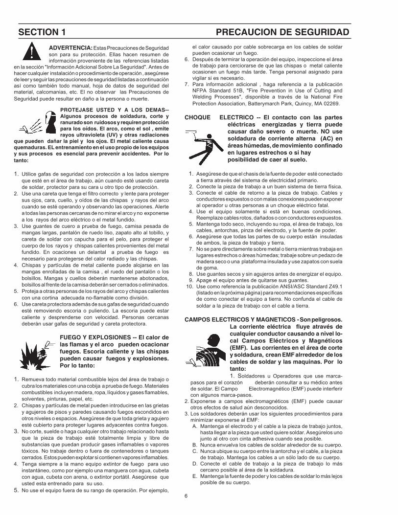
ADVERTENCIA: Estas Precauciones de Seguridadson para su protección. Ellas hacen resumen deinformación proveniente de las referencias listadas
en la sección "Información Adicional Sobre La Seguridad". Antes dehacer cualquier instalación o procedimiento de operación , asegúresede leer y seguir las precauciones de seguridad listadas a continuaciónasí como también todo manual, hoja de datos de seguridad delmaterial, calcomanias, etc. El no observar las Precauciones deSeguridad puede resultar en daño a la persona o muerte.
PROTEJASE USTED Y A LOS DEMAS--Algunos procesos de soldadura, corte yranurado son ruidosos y requiren protecciónpara los oídos. El arco, como el sol , emiterayos ultravioleta (UV) y otras radiaciones
que pueden dañar la piel y los ojos. El metal caliente causaquemaduras. EL entrenamiento en el uso propio de los equiposy sus procesos es esencial para prevenir accidentes. Por lotanto:
1. Utilice gafas de seguridad con protección a los lados siempreque esté en el área de trabajo, aún cuando esté usando caretade soldar, protector para su cara u otro tipo de protección.
2. Use una careta que tenga el filtro correcto y lente para protegersus ojos, cara, cuello, y oídos de las chispas y rayos del arcocuando se esté operando y observando las operaciones. Alertea todas las personas cercanas de no mirar el arco y no exponersea los rayos del arco eléctrico o el metal fundido.
3. Use guantes de cuero a prueba de fuego, camisa pesada demangas largas, pantalón de ruedo liso, zapato alto al tobillo, ycareta de soldar con capucha para el pelo, para proteger elcuerpo de los rayos y chispas calientes provenientes del metalfundido. En ocaciones un delantal a prueba de fuego esnecesario para protegerse del calor radiado y las chispas.
4. Chispas y partículas de metal caliente puede alojarse en lasmangas enrolladas de la camisa , el ruedo del pantalón o losbolsillos. Mangas y cuellos deberán mantenerse abotonados,bolsillos al frente de la camisa deberán ser cerrados o eliminados.
5. Proteja a otras personas de los rayos del arco y chispas calientescon una cortina adecuada no-flamable como división.
6. Use careta protectora además de sus gafas de seguridad cuandoesté removiendo escoria o puliendo. La escoria puede estarcaliente y desprenderse con velocidad. Personas cercanasdeberán usar gafas de seguridad y careta protectora.
FUEGO Y EXPLOSIONES -- El calor delas flamas y el arco pueden ocacionarfuegos. Escoria caliente y las chispaspueden causar fuegos y explosiones.Por lo tanto:
1. Remueva todo material combustible lejos del área de trabajo ocubra los materiales con una cobija a prueba de fuego. Materialescombustibles incluyen madera, ropa, líquidos y gases flamables,solventes, pinturas, papel, etc.
2. Chispas y partículas de metal pueden introducirse en las grietasy agujeros de pisos y paredes causando fuegos escondidos enotros niveles o espacios. Asegúrese de que toda grieta y agujeroesté cubierto para proteger lugares adyacentes contra fuegos.
3. No corte, suelde o haga cualquier otro trabajo relacionado hastaque la pieza de trabajo esté totalmente limpia y libre desubstancias que puedan producir gases inflamables o vaporestóxicos. No trabaje dentro o fuera de contenedores o tanquescerrados. Estos pueden explotar si contienen vapores inflamables.
4. Tenga siempre a la mano equipo extintor de fuego para usoinstantáneo, como por ejemplo una manguera con agua, cubetacon agua, cubeta con arena, o extintor portátil. Asegúrese queusted esta entrenado para su uso.
5. No use el equipo fuera de su rango de operación. Por ejemplo,
el calor causado por cable sobrecarga en los cables de soldarpueden ocasionar un fuego.
6. Después de termirar la operación del equipo, inspeccione el áreade trabajo para cerciorarse de que las chispas o metal calienteocasionen un fuego más tarde. Tenga personal asignado paravigilar si es necesario.
7. Para información adicional , haga referencia a la publicaciónNFPA Standard 51B, "Fire Prevention in Use of Cutting andWelding Processes", disponible a través de la National FireProtection Association, Batterymarch Park, Quincy, MA 02269.
CHOQUE ELECTRICO -- El contacto con las parteseléctricas energizadas y tierra puedecausar daño severo o muerte. NO usesoldadura de corriente alterna (AC) enáreas húmedas, de movimiento confinadoen lugares estrechos o si hayposibilidad de caer al suelo.
1. Asegúrese de que el chasis de la fuente de poder esté conectadoa tierra através del sistema de electricidad primario.
2. Conecte la pieza de trabajo a un buen sistema de tierra física.3. Conecte el cable de retorno a la pieza de trabajo. Cables y
conductores expuestos o con malas conexiones pueden exponeral operador u otras personas a un choque eléctrico fatal.
4. Use el equipo solamente si está en buenas condiciones.Reemplaze cables rotos, dañados o con conductores expuestos.
5. Mantenga todo seco, incluyendo su ropa, el área de trabajo, loscables, antorchas, pinza del electrodo, y la fuente de poder.
6. Asegúrese que todas las partes de su cuerpo están insuladasde ambos, la pieza de trabajo y tierra.
7. No se pare directamente sobre metal o tierra mientras trabaja enlugares estrechos o áreas húmedas; trabaje sobre un pedazo demadera seco o una plataforma insulada y use zapatos con suelade goma.
8. Use guantes secos y sin agujeros antes de energizar el equipo.9. Apage el equipo antes de quitarse sus guantes.
10. Use como referencia la publicación ANSI/ASC Standard Z49.1(listado en la próxima página) para recomendaciones específicasde como conectar el equipo a tierra. No confunda el cable desoldar a la pieza de trabajo con el cable a tierra.
CAMPOS ELECTRICOS Y MAGNETICOS - Son peligrosos.La corriente eléctrica fluye através decualquier conductor causando a nivel lo-cal Campos Eléctricos y Magnéticos(EMF). Las corrientes en el área de cortey soldadura, crean EMF alrrededor de loscables de soldar y las maquinas. Por lotanto:1. Soldadores u Operadores que use marca-
pasos para el corazón deberán consultar a su médico antesde soldar. El Campo Electromagnético (EMF) puede interferircon algunos marca-pasos.
2. Exponerse a campos electromagnéticos (EMF) puede causarotros efectos de salud aún desconocidos.
3. Los soldadores deberán usar los siguientes procedimientos paraminimizar exponerse al EMF:A. Mantenga el electrodo y el cable a la pieza de trabajo juntos,
hasta llegar a la pieza que usted quiere soldar. Asegúrelos unojunto al otro con cinta adhesiva cuando sea posible.
B. Nunca envuelva los cables de soldar alrededor de su cuerpo.C. Nunca ubique su cuerpo entre la antorcha y el cable, a la pieza
de trabajo. Mantega los cables a un sólo lado de su cuerpo.D. Conecte el cable de trabajo a la pieza de trabajo lo más
cercano posible al área de la soldadura.E. Mantenga la fuente de poder y los cables de soldar lo más lejos
posible de su cuerpo.
SECTION 1 PRECAUCION DE SEGURIDAD

7
HUMO Y GASES -- El humo y los gases,pueden causar malestar o daño,particularmente en espacios sinventilación. No inhale el humo o gases.El gas de protección puede causar faltade oxígeno. Por lo tanto:
1. Siempre provea ventilación adecuada en el área detrabajo por medio natural o mecánico. No solde, corte, oranure materiales con hierro galvanizado, acero inoxidable,cobre, zinc, plomo, berílio, o cadmio a menos que proveaventilación mecánica positiva . No respire los gasesproducidos por estos materiales.
2. No opere cerca de lugares donde se aplique substanciasquímicas en aerosol. El calor de los rayos del arco puedenreaccionar con los vapores de hidrocarburo clorinado paraformar un fosfógeno, o gas tóxico, y otros irritant es.
3. Si momentáneamente desarrolla inrritación de ojos, narizo garganta mientras est á operando, es indicación de quela ventilación no es apropiada. Pare de trabajar y tomelas medidas necesarias para mejorar la ventilación enel área de trabajo. No continúe operando si el malestarfísico persiste.
4. Haga referencia a la publicación ANSI/ASC StandardZ49.1 (Vea la lista a continuación) para recomendacionesespecíficas en la ventilación.
5. ADVERTENCIA-- Este producto cuando se utiliza parasoldaduras o cortes, produce humoso gases, los cuales contienenquímicos conocidos por el Estadode California de causar defectos enel nacimiento, o en algunos casos,Cancer. (California Health & SafetyCode §25249.5 et seq.)
MANEJO DE CILINDROS-- Loscilindros, si no son manejadoscorrectamente, pueden romperse yliberar violentamente gases. Roturarepentina del cilindro, válvula, oválvula de escape puede causar dañoo muerte. Por lo tanto:
1. Utilize el gas apropiado para el proceso y utilize unregulador diseñado para operar y reducir la presión delcilindro de gas . No utilice adaptadores. Mantenga lasmangueras y las conexiones en buenas condiciones.Observe las instrucciones de operación del manufactureropara montar el regulador en el cilindro de gas comprimido.
2. Asegure siempre los cilindros en posición vertical yamárrelos con una correa o cadena adecuada paraasegurar el cilindro al carro, transportes, tablilleros, paredes,postes, o armazón. Nunca asegure los cilindros a la mesade trabajo o las piezas que son parte del circuito desoldadura . Este puede ser parte del circuito elélectrico.
3. Cuando el cilindro no está en uso, mantenga la válvula delcilindro cerrada. Ponga el capote de protección sobre laválvula si el regulador no está conectado. Asegure ymueva los cilindros utilizando un carro o transporteadecuado. Evite el manejo brusco de los
Las siguientes publicaciones, disponibles através de laAmerican Welding Society, 550 N.W. LeJuene Road, Miami,FL 33126, son recomendadas para usted:1. ANSI/ASC Z49.1 - "Safety in Welding and Cutting"2. AWS C5.1 - "Recommended Practices for Plasma Arc
Welding"3. AWS C5.2 - "Recommended Practices for Plasma Arc
Cutting"4. AWS C5.3 - "Recommended Practices for Air Carbon Arc
Gouging and Cutting"5. AWS C5.5 - "Recommended Practices for Gas Tungsten
Arc Welding“6. AWS C5.6 - "Recommended Practices for Gas Metal Arc
Welding"“7. AWS SP - "Safe Practices" - Reprint, Welding Handbook.8. ANSI/AWS F4.1, "Recommended Safe Practices for Weld-
ing and Cutting of Containers That Have Held HazardousSubstances."
Significa riesgo inmediato que, de no serevadido, puede resultar inmediatamenteen serio daño personal o la muerte.
Significa el riesgo de un peligro potencialque puede resultar en serio daño per-sonal o la muerte.
Significa el posible riesgo que puederesultar en menores daños a la persona.
MANTENIMIENTO DEL EQUIPO -- Equipodefectuoso o mal mantenido puede causardaño o muerte. Por lo tanto:
1. Siempre tenga personal cualificado para efectuar la instalación, diagnóstico, y mantenimiento delequipo. No ejecute ningún trabajo eléctrico a menosque usted esté cualificado para hacer el trabajo.
2. Antes de dar mantenimiento en el interior de lafuente de poder, desconecte la fuente de poder delsuministro de electricidad primaria.
3. Mantenga los cables, cable a tierra, conexciones, cableprimario, y cualquier otra fuente de poder en buenestado operacional. No opere ningún equipo enmalas condiciones.
4. No abuse del equipo y sus accesorios. Mantenga elequipo lejos de cosas que generen calor comohornos, también lugares húmedos como charcos deagua , aceite o grasa, atmósferas corrosivas y lasinclemencias del tiempo.
5. Mantenga todos los artículos de seguridad y coverturasdel equipo en su posición y en buenas condiciones.
6. Use el equipo sólo para el propósito que fue diseñado.No modifique el equipo en ninguna manera.
INFORMACION ADICIONAL DE SEGURIDAD --Para más información sobre las prácticas deseguridad de los equipos de arco eléctrico parasoldar y cortar, pregunte a su suplidor por unacopia de "Precautions and Safe Practices for ArcWelding, Cutting and Gouging-Form 52-529.
SIGNIFICADO DE LOS SIMBOLOS --Según usted avanza en la lectura deeste folleto: Los Símbolos Significan¡Atención! ¡Esté Alerta! Se trata de suseguridad.
SECTION 1 PRECAUCION DE SEGURIDAD

8
provoquer de graves incendies au contact dematériaux combustibles solides, liquides ou gazeux.Aussi faut-il observer les précautions suivantes:
a. Éloigner suffisamment tous les matériaux combustiblesdu secteur où l’on exécute des soudures ou descoupes à l’arc, à moins de les recouvrir complètementd’une bâche non-inflammable. Ce type de matériauxcomprend notamment le bois, les vêtements, la sciure,l’essence, le kérosène, les peintures, les solvants, legaz naturel, l’acétylène, le propane et autres substancescombustibles semblables.
b. Les étincelles ou les projections de métal incandescentpeuvent tomber dans des fissures du plancher ou dansdes ouvertures des murs et y déclencher une ignitionlente cachée. Veiller à protéger ces ouvertures desétincelles et des projections de métal.
c. N’exécutez pas de soudures, de coupes, d’opérationsde gougeage ou autres travaux à chaud à la surface debarils, bidons, réservoirs ou autres contenants usagés,avant de les avoir nettoyés de toute trace de substancesusceptible de produire des vapeurs inflammables outoxiques.
d. En vue d’assurer la prévention des incendies, il convientde disposer d’un matériel d’extinction prêt à servirimmédiatement, tel qu’un tuyau d’arrosage, un seau àeau, un seau de sable ou un extincteur portatif.
e. Une fois le travail à l’arc terminé, inspectez le secteurde façon à vous assurer qu’aucune étincelle ouprojection de métal incandescent ne risque deprovoquer ultérieurement un feu.
3. CHOC ÉLECTRIQUE-- Le gougeage à l’arc et à l’arc auplasma exige l’emploi de tensions à vide relativementimportantes; or, celles-ci risquent de causer desdommages corporels graves et même mortels en casd’utilisation inadéquate. La gravité du choc électriquereçu dépend du chemin suivi par le courant à travers lecorps humain et de son intensité.
a. Ne laissez jamais de surfaces métalliques sous tensionvenir au contact direct de la peau ou de vêtementshumides. Veillez à porter des gants bien secs.
b. Si vous devez effectuer un travail sur une surfacemétallique ou dans un secteur humide, veillez à assu-rer votre isolation corporelle en portant des gants secset des chaussures à semelles de caoutchouc et en voustenant sur une planche ou une plate-forme sèche.
c. Mettez toujours à la terre le poste de soudage/coupageen le reliant par un câble à une bonne prise de terre.
d. N’utilisez jamais de câbles usés ou endommagés. Nesurchargez jamais le câble. Utilisez toujours unéquipement correctement entretenu.
e. Mettez l’équipement hors tension lorsqu’il n’est pas enservice. une mise à la masse accidentelle peut en effetprovoquer une surchauffe de l’équipement et un dangerd’incendie. Ne pas enrouler ou passer le câble autourd’une partie quelconque du corps.
f. Vérifiez si le câble de masse est bien relié à la pièce enun point aussi proche que possible de la zone de travail.Le branchement des câbles de masse à l’ossature dubâtiment ou en un point éloigné de la zone de travailaugmente en effet le risque de passage d’un courant desortie par des chaînes de
AVERTISSEMENT: Ces règles de sécurité ont pour objetd’ assurer votre protection. Veillez à lire et à observer lesprécautions énoncées ci-dessous avant de monter l’équipement ou de commercer à l’utiliser. Tout défautd’observation de ces précautions risque d’entraîner desblessures graves ou mortelles.
1. PROTECTION INDIVIDUELLE-- Les brûlures de lapeau et des yeux dues au rayonnement de l’arcélectrique ou du métal incandescent, lors dusoudage au plasma ou à l’électrode ou lors dugougeage à l’arc, peuvent s’avérer plus graves quecelles résultant d’une exposition prolongée au soleil.Aussi convient-il d’observer les précautionssuivantes:
a. Portez un écran facial adéquat muni des plaquesprotectrices et des verres filtrants appropriés afin devous protéger les yeux, le visage, le cou et lesoreilles des étincelles et du rayonnement de l’arcélectrique lorsque vous effectuez des soudures oudes coupes ou lorsque vous en observezl’exécution.
AVERTISSEZ les personnes se trouvant à proximitéde façon à ce qu’elles ne regardent pas l’arc et à cequ’elles ne s’exposent pas à son rayonnement, ni àcelui du métal incandescent.
b. Portez des gants ignifugés à crispins, une tuniqueépaisse à manches longues, des pantalons sansrebord, des chaussures à embout d’acier et uncasque de soudage ou une calotte de protection, afind’éviter d’exposer la peau au rayonnement de l’arcélectrique ou du métal incandescent. ll est égalementsouhaitable d’utiliser un tablier ininflammable defaçon à se protéger des étincelles et du rayonnementthermique.
c. Les étincelles ou les projections de métalincandescent risquent de se loger dans desmanches retroussées, des bords relevés depantalons ou dans des poches. Aussi convient-il degarder boutonnés le col et les manches et de porterdes vêtements sans poches à l’avant.
d. Protégez des étincelles et du rayonnement de l’arcélectrique les autres personnes travaillant à proximitéà l’aide d’un écran ininflammable adéquat.
e. Ne jamais omettre de porter des lunettes de sécuritélorsque vous vous trouvez dans un secteur où l’oneffectue des opérations de soudage ou de coupageà l’arc. Utilisez des lunettes de sécurité à écrans ouverres latéraux pour piquer ou meûler le laitier. Lespiquetures incandescentes de laitier peuvent êtreprojetées à des distances considérables. Lespersonnes se trouvant à proximité doivent égalementporter des lunettes de protection.
f. Le gougeage à l’arc et le soudage à l’arc au plasmaproduisent un niveau de bruit extrêmement élevé (de100 à 114 dB) et exigent par conséquent l’emploi dedispositifs appropriés de protection auditive.
2 PRÉVENTION DES INCENDES-- Les projections delaitier incandescent ou d’étincelles peuvent
SECTION 1 PRÉCAUTIONS DE SÉCURITÉ
9
levage, des câbles de grue ou divers cheminsélectriques.
g. Empêchez l’apparition de toute humidité, notammentsur vos vêtements, à la surface de l’emplacement detravail, des câbles, du porte-électrode et du poste desoudage/coupage. Réparez immédiatement toutefuite d’eau.
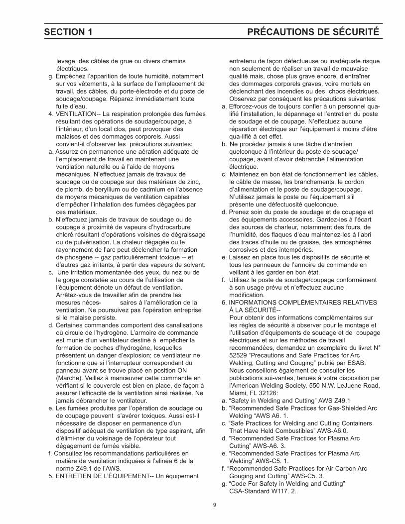
4. VENTILATION-- La respiration prolongée des fuméesrésultant des opérations de soudage/coupage, àl’intérieur, d’un local clos, peut provoquer desmalaises et des dommages corporels. Aussiconvient-il d’observer les précautions suivantes:
a. Assurez en permanence une aération adéquate del’emplacement de travail en maintenant uneventilation naturelle ou à l’aide de moyensmécaniques. N’effectuez jamais de travaux desoudage ou de coupage sur des matériaux de zinc,de plomb, de beryllium ou de cadmium en l’absencede moyens mécaniques de ventilation capablesd’empêcher l’inhalation des fumées dégagées parces matériaux.
b. N’effectuez jamais de travaux de soudage ou decoupage à proximité de vapeurs d’hydrocarburechloré résultant d’opérations voisines de dégraissageou de pulvérisation. La chaleur dégagée ou lerayonnement de l’arc peut déclencher la formationde phosgène -- gaz particulièrement toxique -- etd’autres gaz irritants, à partir des vapeurs de solvant.
c. Une irritation momentanée des yeux, du nez ou dela gorge constatée au cours de l’utilisation del’équipement dénote un défaut de ventilation.Arrêtez-vous de travailler afin de prendre lesmesures néces- saires à l’amélioration de laventilation. Ne poursuivez pas l’opération entreprisesi le malaise persiste.
d. Certaines commandes comportent des canalisationsoù circule de l’hydrogène. L’armoire de commandeest munie d’un ventilateur destiné à empêcher laformation de poches d’hydrogène, lesquellesprésentent un danger d’explosion; ce ventilateur nefonctionne que si l’interrupteur correspondant dupanneau avant se trouve placé en position ON(Marche). Veillez à manœuvrer cette commande envérifiant si le couvercle est bien en place, de façon àassurer l’efficacité de la ventilation ainsi réalisée. Nejamais débrancher le ventilateur.
e. Les fumées produites par l’opération de soudage oude coupage peuvent s’avérer toxiques. Aussi est-ilnécessaire de disposer en permanence d’undispositif adéquat de ventilation de type aspirant, afind’élimi-ner du voisinage de l’opérateur toutdégagement de fumée visible.
f. Consultez les recommandations particulières enmatière de ventilation indiquées à l’alinéa 6 de lanorme Z49.1 de l’AWS.
5. ENTRETIEN DE L’ÉQUIPEMENT-- Un équipement
entretenu de façon défectueuse ou inadéquate risquenon seulement de réaliser un travail de mauvaisequalité mais, chose plus grave encore, d’entraînerdes dommages corporels graves, voire mortels endéclenchant des incendies ou des chocs électriques.Observez par conséquent les précautions suivantes:
a. Efforcez-vous de toujours confier à un personnel qua-lifié l’installation, le dépannage et l’entretien du postede soudage et de coupage. N’effectuez aucuneréparation électrique sur l’équipement à moins d’êtrequa-lifié à cet effet.
b. Ne procédez jamais à une tâche d’entretienquelconque à l’intérieur du poste de soudage/coupage, avant d’avoir débranché l’alimentationélectrique.
c. Maintenez en bon état de fonctionnement les câbles,le câble de masse, les branchements, le cordond’alimentation et le poste de soudage/coupage.N’utilisez jamais le poste ou l’équipement s’ilprésente une défectuosité quelconque.
d. Prenez soin du poste de soudage et de coupage etdes équipements accessoires. Gardez-les à l’écartdes sources de charleur, notamment des fours, del’humidité, des flaques d’eau maintenez-les à l’abrides traces d’huile ou de graisse, des atmosphèrescorrosives et des intempéries.
e. Laissez en place tous les dispositifs de sécurité ettous les panneaux de l’armoire de commande enveillant à les garder en bon état.
f. Utilisez le poste de soudage/coupage conformémentà son usage prévu et n’effectuez aucunemodification.
6. INFORMATIONS COMPLÉMENTAIRES RELATIVESÀ LA SÉCURITÉ--
Pour obtenir des informations complémentaires surles règles de sécurité à observer pour le montage etl’utilisation d’équipements de soudage et de coupageélectriques et sur les méthodes de travailrecommandées, demandez un exemplaire du livret N°52529 “Precautions and Safe Practices for ArcWelding, Cutting and Gouging” publié par ESAB.Nous conseillons également de consulter lespublications sui-vantes, tenues à votre disposition parl’American Welding Society, 550 N.W. LeJuene Road,Miami, FL 32126:
a. “Safety in Welding and Cutting” AWS Z49.1b. “Recommended Safe Practices for Gas-Shielded Arc
Welding “AWS A6. 1.c. “Safe Practices for Welding and Cutting Containers
That Have Held Combustibles” AWS-A6.0.d. “Recommended Safe Practices for Plasma Arc
Cutting” AWS-A6. 3.e. “Recommended Safe Practices for Plasma Arc
Welding” AWS-C5. 1.f. “Recommended Safe Practices for Air Carbon Arc
Gouging and Cutting” AWS-C5. 3.g. “Code For Safety in Welding and Cutting”
CSA-Standard W117. 2.
SECTION 1 PRÉCAUTIONS DE SÉCURITÉ

10
The PowerCut 1500 plasma cutting package combinesthe proven reliability of the PowerCut-875 and 1125with the newly designed PT-32EH torch. The verystrong composite case material makes the PowerCut-1500 an excellent addition to any equipment rentalfleet. The PT-32EH plasma cutting torch is designed toprovide increased performance and longer consumablelife resulting in higher production rates at lower costs.
Multi input voltage (208)230/460V, easily changedon back of machine.
Cuts 1-1/2 inch Designed for rugged treatment and outdoor use
makes the PowerCut an excellent choice for rentalfleet and construction site uses.
More performance features than any machines in itsclass.
Delivers big machine cutting power in a rugged,lightweight package.
Pilot arc start facilitates starting on painted andcoated metals.
Long-life consumables and repairable torch minimizeoperating costs.
Arrives ready to cut, with torch connected and front-end parts in place, for the ultimate in operatorconvenience.
Trigger lock-in for long-cut operator comfort. Built in line conditioner – handles poor power lines. Auto Drag feature allows torch to drag on workpiece
without damage to the nozzle for easy templatefollowing.
For longer nozzle life while drag cutting, a 40 ampnozzle is available (P/N 0558002908)
Self protectant against improper input voltage Multiple troubleshooting lights on front panel Superior gouging performance Three year warranty on console. One year warranty on torch.
PowerCut-1500 Plasmarc™ Cutting Package
Specifications: PowerCut-1500Cuts 1-1/2 in. (38mm); severs 1-3/4 in. (45mm)1 ph. Input .............................. 208/230 vac, 1 ph, 50/60 Hz, 82/74 A1 ph. Output ........................................... 90 amps @ 40% duty cycle3 ph. Input .............................. 208/230 vac, 3 ph, 50/60 Hz, 44/40 A
........................................... 230/460 vac, 3 ph, 50/60 Hz, 40/27 A
........................................................ 400 vac, 3ph, 50/60 Hz, 26 A
........................................................ 575 vac, 3ph, 50/60 Hz, 11 A3 ph. Output ........................................... 90 amps @ 60% duty cycle
Dimensions ........................................................ W = 13.1” (328mm)w/ optional Torch Storage ............................... W= 16.1" (403mm)........................................................................ H = 16.5” (419mm)........................................................................ D = 32.5” (826mm)
Weight ..................................................................... 94 lbs. (42.7kg)Shipping Weight ..................................................... 109 lbs. (49.5kg)Air Requirements ............ 360 cfh @ 75 psig (170 l/min @ 5.2 bars)
TorchPowerCut-1500 uses the PT-32EH torch. For complete list
and breakdown of parts, refer to PT-32 data page.
Ordering Information:PowerCut-1500, 230/460 V, 25’ PT-32EH ....................0558001942PowerCut-1500, 230/460 V, 50’ PT-32EH ....................0558001943PowerCut-1500, 575 V, 25’ PT-32EH ..........................0558001948PowerCut-1500, 575 V, 50’ PT- 32EH ..........................0558001949PowerCut-1500, 400 V, “CE” 25’ PT-32EH ...................0558001945PowerCut-1500, 400 V, “CE” 50’ PT-32EH ...................0558001946
Consoles:PowerCut-1500 (208)230/460 V,
50/60 Hz, 1/3-ph ..................................................... 0558001944PowerCut-1500 575 V, 50/60 Hz, 3-ph ....................... 0558001950
PT-32EH Torches:PT-32EH Torch, 90o head, 25-ft. ............................... 0558003548PT-32EH Torch, 90o head, 50-ft. ............................... 0558003549PT-32EH Spare Parts Kit (see Table 1-1) ................. 0558003062
SECTION 1 DESCRIPTION

11
Optional Accessories:90 amp Spare Parts Kit ...............................................0558003062Plasma Flow Measuring Kit:
This valuable troubleshooting tool allows measurement ofthe actual plasma gas flow through the torch .................... 19765
Torch Guide Kit:This complete kit, in a rugged plastic carrying case, includes
attachments for circle and straight line cutting on ferrous andnon-ferrous metals, 1 3/4" - 42" Radius, Deluxe .......0558003258Basic, 1/34” - 28” Radius ..........................................0558002675
Stand-off GuideFor proper stand-off distance when drag cutting .......0558002393
40 amp Drag Nozzle ................................................. 0558002908Gouging Nozzle ..........................................................0558003089Heat Shield Gouging ................................................ 0558003090Drag Heat Shield .........................................................0558003374
Wheel KitFor easy transport of system ....................................0558003060
Torch WrapThis enables operator to store spare parts kit, wrap torch
and work cable for easy transport and storage ..........0558003059
Description P/N Quantity
Heat Shield 0558001957 290 amp Nozzle 0558002837 440 amp drag Nozzle 0558002908 1Electrode 0558001969 3Valve Pin 0558001959 1Fuse 2amp, 600vac 0558003075Stand-off Guide 0558002393 1Wrench 19129 1Lubricant 17672 1
Contents of PT-32 Spare Parts Kit, P/N 0558003062
The PowerCut-1500 comes out of the box ready to go. The torch isattached with parts in place, primary cord is attached (including plugon 230 model), and the filter/regulator is installed. Just hook up theair, plug it in and cut.
Heat Shield0558001957
Valve Pin0558001959
Nozzle40 AMP - 0558002908 (Drag Cutting)50/70 AMP - 0558002618
O-Ring - 85W51(Supplied with head)
Electrode0558001969
SECTION 1 DESCRIPTION
Powercut shown with Optional Torch Wrapand Spare Parts Kit Holder installed.

12
SECTION 1 DESCRIPTION
1.1 GENERAL
The Powercut-1500 is a compact, completely self-contained plasma cuttingsystem. As shipped, the system is fully assembled and ready to cut afterbeing connected to input power and a source of compressed air (90-150 psi).The Powercut-1500 package uses the heavy-duty PT-32 torch to deliver cuttingpower for severing materials up to 1-1/2 inch thick. Refer to the followingparagraphs for descriptions of the Powercut-1500 packages available as wellas performance specifications.
1.2 SCOPE
The purpose of this manual is to provide the operator with all the informationrequired to install and operate the Powercut-1500 plasma arc cuttingpackage. Technical reference material is also provided to assist in trouble-shooting the cutting package.
Use only The ESAB PT-32 Plasmarctorch with this console. Use of torchesnot designed for use with this consolecould create an ELECTRIC SHOCKHAZARD.

13
SECTION 2 INSTALLATION
2.1 GENERAL
Proper installation is important for satisfactory and trouble-free operation ofthe PowerCut 1500 cutting package. It is suggested that each step in thissection be studied carefully and followed closely.
2.2 EQUIPMENT REQUIRED
A source of clean, dry air that supplies 350 cfh at 80 psig is required for thecutting operation. The air supply should not exceed 150 psig (the maximuminlet pressure rating of the air filter-regulator supplied with the package).
2.3 LOCATION
Adequate ventilation is necessary to provide proper cooling of the PowerCut1500. The amount of dirt, dust, and excessive heat to which the equipmentis exposed, should be minimized. There should be at least one foot ofclearance between the PowerCut 1500 power source and wall or any otherobstruction to allow freedom of air movement through the power source.
2.4 INSPECTION
A. Remove the shipping container and all packing material and inspect forevidence of concealed damage which may not have been apparentupon receipt of the PowerCut 1500. Notify the carrier of any defects ordamage at once.
B. Check container for any loose parts prior to disposing of shippingmaterials.
C. Check air louvers and any other openings to ensure that any obstructionis removed.
2.5 PRIMARY ELECTRICAL INPUT CONNECTIONS (FIGURE 2-1)
The PowerCut 1500 consoles are equipped with approximately 10-ft. of 4-conductor input power cable for 3-phase connection. If single-phase connec-tion is desired, tape back the red wire on the input power cable. Connect thesingle phase input to the white and black wires only. When operating thismachine from a single-phase source, it must be connected to a dedicated 100Amp feed. Due to the higher input current requirements, the duty cycle of themachine is lower than in three-phase operation.
Installing or placing any type of filter-ing device will restrict the volume ofintake air, thereby subjecting the powersource internal components to over-heating. The warranty is void if anytype of filter device is used.
ELECTRIC SHOCK CAN KILL! Precau-tionary measures should be taken toprovide maximum protection againstelectrical shock. Be sure that all poweris off by opening the line (wall) discon-nect switch and by unplugging thepower cord to the unit when connec-tions are made inside of the powersource.
CUSTOMER FUSED LINE DISCONNECT SWITCH(See Table 2.1 and WARNING in regards to chassis ground in Section 2.5.)

14
SECTION 2 INSTALLATION
2.5.1 INPUT VOLTAGE CHANGEOVER
200 - 230 or 460 ModeTo simplify the use of the ESAB Powercut 1500 with different input volt-ages, it has been equipped with a convenient 230/460 selector switch lo-cated on the back panel of the unit. The Powercut 1500 is also equippedwith protective fuse that will prevent damage to the power source in theevent that the input voltage switch is not set correctly and the unit is pow-ered on.
A line (wall) disconnect switch with fuses or circuit breakers should be pro-vided at the main power panel (see Fig. 2-1 and Table 2-1 for fuse sizes).The input power cable of the console may be connected directly to thedisconnect switch or you may purchase a proper plug and receptacle froma local electrical supplier. If using plug/receptacle combination, see Table2-1 for recommended input conductors for connecting receptacle to linedisconnect switch.
Table 2-1. Recommended Sizes ForInput Conductors and Line Fuses
Input Requirements Input & Gnd FuseVolts Phase Amps Conductor Size
CU/AWG Amps208 1 82A 6 100208 3 44A/Ph. 6 80230 1 74A 6 100230 3 40A/Ph. 6 80460 3 27 6 50
Before making any connections to thepower source output terminals, makesure that all primary input power to thepower source is deenergized (off) atthe main disconnect switch and thatthe input power cable is unplugged.
Input VoltageSelector Switch
Fuse*
ELECTRIC SHOCK CAN KILL! Beforemaking electrical input connections tothe power source, "Machinery LockoutProcedures" should be employed. Ifthe connections are to be made from aline disconnect switch, place the switchin the off position and padlock it toprevent inadvertent tripping . If theconnection is made from a fusebox,remove the corresponding fuses andpadlock the box cover. If it is not pos-sible to use padlocks, attach a red tagto the line disconnect switch (or fusebox) warning others that the circuit isbeing worked on.
The chassis must be connected to anapproved electrical ground. Failure todo so may result in electrical shock,severe burns or death.
Before connecting to input power, make sure there is a line (wall) disconnectswitch with fuses or circuit breakers at the main power panel. You may eitheruse the factory-installed input power cable (No. 6 AWG, 4/c, type SO (90 °C),12 ft (3.7 m) length) or provide your own input power leads. If you choose toprovide your own, make sure they are insulated copper conductors. You musthave two (single-phase) or three (three-phase) power leads and one groundwire. The wires may be heavy rubber covered cable or may be run in a solidor flexible conduit. Refer to Table 2-1 for recommended input conductors andline fuse sizes.
INPUT VOLTAGE SELECTORNOT POWER
ON - OFF SWITCHUSE POWER SWITCH ON FRONT
PANEL TO TURNON AND OFF

15
SECTION 2 INSTALLATION
Figure 2-1. PowerCut 1500 Interconnection Diagram
WORK
SAFETYGROUND
PT-32
Prefiltered DRY AIRSUPPLY (CustomerSupplied)(90 to 150 psig max)
2.6 SECONDARY (OUTPUT) CONNECTIONS (REFER TOFIG. 2-1)
The Torch comes factory installed.
Connect your air supply to the inlet connection of the filter-regulator.
PRIMARY INPUTPOWER CABLE
Clamp the work cable to theworkpiece. Be sure theworkpiece is connected to anapproved earth ground with aproperly sized ground cable.
FUSEDDISCONNECT
BOX

16
SECTION 3 OPERATION
3.1 OPERATION
3.2 PowerCut 1500 CONTROLS (FIGURE 3-1A)
A. Power Switch. When placed in ON position, the green pilot light willglow indicating control circuit is energized.
B. Air Test Switch. When placed in Test position, air filter-regulator canbe adjusted to desired pressure (80 psig) before cutting operations.Allow air to flow for a few minutes. This should remove any condensationthat may have accumulated during shutdown period. Be sure to placeswitch in OPERATE position before starting cutting operations.
C. Trigger Lock Switch. When placed in LOCK position, this permitsreleasing torch switch button after cutting arc has been initiated. Toextinguish arc at end of cut, press and release torch switch button againor pull torch away from work. When placed in UNLOCK position, torchswitch must be held closed by the operator during the entire cuttingoperation and then released at the end of cut.
D. Output Current Control. Adjustable from 20 to 90 amperes.
A DB C
Figure 3-1A. PowerCut 1500 Controls
17
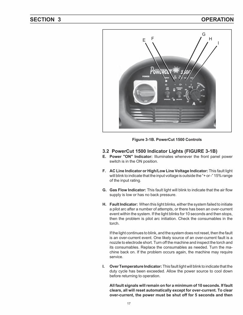
Figure 3-1B. PowerCut 1500 Controls
3.2 PowerCut 1500 Indicator Lights (FIGURE 3-1B)E. Power "ON" Indicator: Illuminates whenever the front panel power
switch is in the ON position.
F. AC Line Indicator or High/Low Line Voltage Indicator: This fault lightwill blink to indicate that the input voltage is outside the “+ or -” 15% rangeof the input rating.
G. Gas Flow Indicator: This fault light will blink to indicate that the air flowsupply is low or has no back pressure.
H. Fault Indicator: When this light blinks, either the system failed to initiatea pilot arc after a number of attempts, or there has been an over-currentevent within the system. If the light blinks for 10 seconds and then stops,then the problem is pilot arc initiation. Check the consumables in thetorch.
If the light continues to blink, and the system does not reset, then the faultis an over-current event. One likely source of an over-current fault is anozzle to electrode short. Turn off the machine and inspect the torch andits consumables. Replace the consumables as needed. Turn the ma-chine back on. If the problem occurs again, the machine may requireservice.
I. Over Temperature Indicator: This fault light will blink to indicate that theduty cycle has been exceeded. Allow the power source to cool downbefore returning to operation.
All fault signals will remain on for a minimum of 10 seconds. If faultclears, all will reset automatically except for over-current. To clearover-current, the power must be shut off for 5 seconds and then
SECTION 3 OPERATION
E HFG
I

18
SECTION 3 OPERATIONturned back on.
3.3 CUTTING WITH THE POWERCUT-1500
Use the following procedures to cut with the PT-32 torch (Figure 3-4).
A. Make sure that the wall disconnect switch is on. Turn on the Front PanelPower Switch.
B. Set Pressure Regulator to 80 psig.C. Hold the torch nozzle approximately 1/8 to 3/16 inch above the work and
tilted at about 15 - 30°. This reduces the chance of spatter entering thenozzle. If the PT-32's standoff guide P/N 0558002393 is being used, thedistance between Electrode and Work Piece will be approx. 3/16-inch.
D. Depress the torch switch. Air should flow from the torch nozzle.E. Two seconds after depressing the torch switch, the pilot arc should
start. The main arc should immediately follow, allowing the cut to begin.(If using the trigger LOCK mode, torch switch may be released afterestablishing the cutting arc.)
F. After starting the cut, the torch should be maintained at a 5-15° forwardangle (Figure 3-2). This angle is especially useful in helping to createa "drop" cut. When not using the standoff guide, the nozzle should be
CUTDIRECTION
Figure 3-2. Recommended Torch Angle of 5° to 15°
IMPORTANT!!!Maintain Proper
Stand-Off Distance3/16 to 1/4 Inch
Power Output increases with Stand Off Distance!
Standoff vs. Power Output
ELECTRIC SHOCK can kill.• Do NOT operate the unit with the
cover removed.• Do NOT apply power to the unit
while holding or carrying the unit.• Do NOT touch any torch parts
forward of the torch handle (nozzle,heat shield, electrode, etc.) withpower switch on.
ARC RAYS can burn eyes and skin;NOISE can damage hearing.
• Wear welding helmet with No. 6 or 7lens shade.
• Wear eye, ear, and body protection.
Position the PowerCut 1500 at least 10feet (3 meters) from the cutting area.Sparks and hot slag from the cuttingoperation can damage the unit.

19
SECTION 3 OPERATION
held approximately 1/4 inch from the work.E. When ending a cut, the torch switch should be released (press and
release if using trigger LOCK mode) and the torch lifted off the workpiecejust before the end of the cut. This is to prevent the high frequency fromreigniting after cutting arc extinguishes and causing damage to thenozzle (double arcing).
F. For rapid re-starts, such as grate or heavy mesh cutting, do not releasethe torch switch. In the postflow mode, the arc can be re-startedimmediately by depressing the torch switch. This avoids the 2-secondpreflow portion of the cutting cycle.
HEAT SHIELD0558001957
NOZZLE90 Amp 0558002837
ELECTRODE0558001969
VALVE PIN00558001959
O-RINGSUPPLIED
WITH HEAD85W51
Fig 3.3. Exploded View of PT-32 Torch

20
THIN GAUGE MATERIALSCAN BE CUT WITH 1/16" (1.6 mm)TORCH-TO-WORK DISTANCEADJUST TO 3/16" (4.8 mm) FORMATERIALS OVER 1/4" (6.4 mm)THICK
ADJUST GUIDE BY TURNINGIN A CLOCKWISE DIRECTIONONLY. THIS WILL PREVENTACCIDENTAL LOOSENINGOF SHIELD.
STEEL GUARDSTAND OFF GUIDEP/N 0558002393
IF GUIDE IS TOOTIGHT ON SHIELD,OPEN SLOT WITHSCREWDRIVER.
IF TOO LOOSE, CLOSESLOT WITH VISE ORLARGE PLIERS.
1/16" (1.6 mm) TO1/4" (6.4 mm)TORCH-TO-WORK
GUIDE AGAINSTSTRAIGHT EDGEOR FREE-HANDCUT
Figure 3-4. Installation and Operation of Steel Heat Shield Guards
SECTION 3 OPERATION

21
SECTION 3 OPERATION
WHEN THE ARC BREAKSTHROUGH THE WORK,BRING THE TORCH TO ANUPRIGHT POSITION ANDPROCEED TO CUT.
TO START A PIERCE, TILT THETORCH TO PREVENT MOLTENMATERIAL FROM COMING BACKAGAINST AND DAMAGING THETORCH.
1
2
Figure 3-5. Piercing Technique using the PT-32
3.4 POSSIBLE CUTTING ISSUES
Drag cutting, even with lower currentlevels may significantly reduce the lifeof torch consumables. Attempting toDrag Cut with higher currents (40amps) may cause immediate cata-strophic consumable damage.
Figure 3-6. Electrode Wear LimitNOTE: When replacing the nozzle, always inspect the electrode for wear. If
more than .06" of electrode Hafnium has eroded, replace theelectrode. If the electrode is used beyond this recommended wearlimit, damage to the torch and power source may occur. Nozzle lifeis also greatly reduced when using the electrode below the recom-mended limit. Refer to Figure 3-3.
REPLACE ELECTRODE BEFOREPITTING BECOMES DEEPER THAN.06 INCH (1.5 MM)
Replace when erodedbeyond.06"(1.5mm) Depth.
NEW WORN
3.3.1. Drag Cutting with the PT-32 torch / PowerCut 1500 package.
LOW CURRENT AUTO-DRAG FEATUREIf drag cutting is desired for thin material under 3/8" thick, remove the standard90 amp nozzle from the PT-32 torch and install ESAB's 40 amp nozzle (P/N0558002908). Lower the current level setting to be within the AUTO-DRAG range of 20 to 40 amps (see Auto Drag Scale on front panel). Thenfollow steps in Section (3.3). Also refer to PT-32 Instruction Manual No. F-15-440.
HIGH CURRENT DRAG CUTTINGIf drag cutting is desired on materials above 3/8” thick, be sure that the 90 ampnozzle (P/N 0558002837) is installed in the PT-32 torch. Attach ESAB'sstand-off guide (P/N 0558002393) and operate as shown in Figure 3.4.

22
Listed below are common cutting problems followed by the probable causeof each. If problems are determined to be caused by the PowerCut 1500, referto the maintenance section of this manual. If the problem is not corrected afterreferring to the maintenance section, contact your ESAB distributor.
A. Insufficient Penetration.
1. Current too low.2. Cutting speed too fast.3. Damaged cutting nozzle.4. Improper air pressure.5. Low air flow rate.
B. Main Arc Extinguishes.
1. Cutting speed too slow.2. Worn electrode.
C. Dross Formation. (In some materials and thicknesses, it may beimpossible to get dross-free cuts.)
1. Current too low.2. Cutting speed too fast or too slow.3. Improper air pressure.4. Faulty nozzle or electrode.5. Low air flow rate.
D. Double Arcing. (Damaged Nozzle Orifice.)
1. Low air pressure.2. Damaged cutting nozzle.3. Loose cutting nozzle.4. Heavy spatter accumulation on nozzle.
E. Uneven Arc.
1. Damaged cutting nozzle or worn electrode.
F. Unstable Cutting Conditions.
1. Incorrect cutting speed.2. Loose cable or hose connections.3. Electrode and/or cutting nozzle in poor condition.
G. Main Arc Does Not Strike.
1. Worn electrode.2. Loose connections.3. Work cable not attached.
H. Poor Consumable Life.
1. Improper gas pressure.2. Contaminated air supply.3. Low air flow rate.
SECTION 3 OPERATION
23
SECTION 4 MAINTENANCE
4.1 GENERAL
If this equipment does not operate properly, stop work immediately andinvestigate the cause of the malfunction. Maintenance work must beperformed by an experienced person, and electrical work by a trainedelectrician. Do not permit untrained persons to inspect, clean, or repairthis equipment. Use only recommended replacement parts.
Be sure that the wall disconnect switch or wall circuit breaker isopen before attempting any inspection or work inside of thePowercut-1500.
4.2 INSPECTION AND CLEANING
Frequent inspection and cleaning of the Powercut-1500 is recommendedfor safety and proper operation. Some suggestions for inspecting andcleaning are as follows:
A. Check work cable for secured connection to workpiece.B. Check safety earth ground at workpiece and at power source chassis.C. Check heat shield on torch. It should be replaced if damaged.D. Check the torch electrode and cutting nozzle for wear on a daily basis.
Remove spatter or replace if necessary.E. Make sure cable and hoses are not damaged or kinked.F. Make sure all plugs, fittings, and ground connections are tight.G. With all input power disconnected, and wearing proper eye and face
protection, blow out the inside of the Powercut-1500 using low-pressuredry compressed air.
Water or oil occasionally accumulates in compressed air lines. Besure to direct the first blast of air away from the equipment to avoiddamage to the Powercut-1500.
H. Occasionally, bleed all water from the filter beneath the air filter-regulator.
4.3 PT-32 TORCH CONSUMABLE PARTS
Make sure power switch on POWERCUT-1500 is in OFF positionbefore working on the torch.
The PT-32 torch head contains a gas flow check valve that acts inconjunction with the flow switch and circuitry within the power source.This system prevents the torch from being energized with high voltageif the torch switch is accidentally closed when the shield is removed.Always replace torch with the proper torch manufactured by ESAB sinceit alone contains ESAB¹s patented safety interlock.
To assemble the consumable parts, refer to Figure 4-1 .
24
SECTION 4 MAINTENANCE
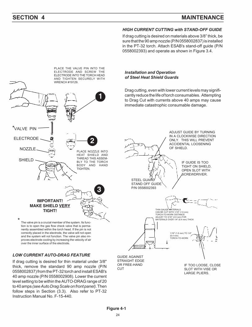
ELECTRODE
NOZZLE
SHIELD
IMPORTANT!MAKE SHIELD VERY
TIGHT!
VALVE PIN
* The valve pin is a crucial member of the system. Its func-tion is to open the gas flow check valve that is perma-nently assembled within the torch head. If the pin is notcorrectly placed in the electrode, the valve will not openand the system will not function. The valve pin also im-proves electrode cooling by increasing the velocity of airover the inner surface of the electrode.
PLACE NOZZLE INTOHEAT SHIELD ANDTHREAD THIS ASSEM-BLY TO THE TORCHBODY AND HANDTIGHTEN.
PLACE THE VALVE PIN INTO THEELECTRODE AND SCREW THEELECTRODE INTO THE TORCH HEADAND TIGHTEN SECURELY WITHWRENCH #19129.
1
2
3
*
THIN GAUGE MATERIALSCAN BE CUT WITH 1/16" (1.6 mm)TORCH-TO-WORK DISTANCEADJUST TO 3/16" (4.8 mm) FORMATERIALS OVER 1/4" (6.4 mm) THICK
ADJUST GUIDE BY TURNINGIN A CLOCKWISE DIRECTIONONLY. THIS WILL PREVENTACCIDENTAL LOOSENINGOF SHIELD.
STEEL GUARDSTAND OFF GUIDEP/N 0558002393
IF GUIDE IS TOOTIGHT ON SHIELD,OPEN SLOT WITHSCREWDRIVER.
IF TOO LOOSE, CLOSESLOT WITH VISE ORLARGE PLIERS.
1/16" (1.6 mm) TO 1/4"(6.4 mm)TORCH-TO-WORK
GUIDE AGAINSTSTRAIGHT EDGEOR FREE-HANDCUT
LOW CURRENT AUTO-DRAG FEATUREIf drag cutting is desired for thin material under 3/8"thick, remove the standard 90 amp nozzle (P/N0558002837) from the PT-32 torch and install ESAB's40 amp nozzle (P/N 0558002908). Lower the currentlevel setting to be within the AUTO-DRAG range of 20to 40 amps (see Auto Drag Scale on front panel). Thenfollow steps in Section (3.3). Also refer to PT-32Instruction Manual No. F-15-440.
HIGH CURRENT CUTTING with STAND-OFF GUIDEIf drag cutting is desired on materials above 3/8” thick, besure that the 90 amp nozzle (P/N 0558002837) is installedin the PT-32 torch. Attach ESAB's stand-off guide (P/N0558002393) and operate as shown in Figure 3.4.
Installation and Operationof Steel Heat Shield Guards
Drag cutting, even with lower current levels may signifi-cantly reduce the life of torch consumables. Attemptingto Drag Cut with currents above 40 amps may causeimmediate catastrophic consumable damage.
Figure 4-1

25
4.4 IGBT Handling & Replacement
Since IGBT gates are insulated from any other conducting region, careshould be taken to prevent static build up, which could possibly damagegate oxides. All IGBT modules are shipped from the factory with conduc-tive foam contacting the gate and emitter sense pins.
Always ground parts touching gate pins during installation. In general,standard ESD precautions application to FETs should be followed.
Other handling precautions that should also be observed are as follows:
• Use grounded work station with grounded floors and grounded wriststraps when handling devices.
• Use a 100Ω resistor in series with the gate when performing curvetracer tests.
• Never install devices into systems with power connected to thesystem.
• Use soldering irons with grounded tips when soldering to gate termi-nals.
When mounting IGBT modules on a heatsink, certain precautions shouldbe taken to prevent any damage against a sudden torque. If a suddentorque (“one-sided tightening”) is applied at only one mounting terminal theceramic insulation plate or silicon chip inside the module may get dam-aged.
The mounting screws are to be fastened in the order shown in Figure 4-2.Also, care must be taken to achieve maximum contact (i.e. minimumcontact thermal resistance) for the best heat dissipation.
Application of a thermal pad on the contact surface improves its thermalconductivity. See Replacement Parts section for the required pad.
A torque wrench should be used. Tighten mounting screws to 28 in-lbs;wire connecting screws to 19 in-lbs. If torque is too heavy, the device candamage like the above “one-sided tightening”.
SECTION 4 MAINTENANCE

26
SECTION 4 MAINTENANCE
Figure 4-2. Screw Fastening Order
Two-Point Mounting TypeTemporary tightening
Final tightening
Four-Point Mounting TypeTemporary tightening
Final tightening

27
SECTION 5 TROUBLESHOOTING
5.1TROUBLESHOOTING
ELECTRIC SHOCK CAN KILL! Be sure that all primary power to themachine has been externally disconnected. Open the line (wall)disconnect switch or circuit breaker before attempting inspection orwork inside of the power source.
Check the problem against the symptoms in the following troubleshootingguide. The remedy may be quite simple. If the cause cannot be quicklylocated, shut off the input power, open up the unit, and perform a simplevisual inspection of all the components and wiring. Check for secureterminal connections, loose or burned wiring or components, bulged orleaking capacitors, or any other sign of damage or discoloration.
The cause of control malfunctions can be found by referring to thesequence of operations and electrical schematic diagram (Figure 5-1) andchecking the various components. A volt-ohmmeter will be necessary forsome of these checks.
Voltages in plasma cutting equipment are high enough to causeserious injury or possibly death. Be particularly careful aroundequipment when the covers are removed.
NOTE
Before checking voltages in the circuit, disconnect the power from thehigh frequency PC Board (PCB-2, Connector J2) to avoid damaging yourvoltmeter.

28
SECTION 5 TROUBLESHOOTING
5.2TROUBLESHOOTING GUIDE
A. Power Light does not come on.
1. Visually inspect the machine for any damage.
2. Check following:
a. Check if the machine power cord is plugged into the inputpower receptacle.
b. Measure the input power at the receptacle. If not present, thencheck the wall disconnect switch and it’s fuses.
c. Check Fuse (F1).
3. If above items check OK , the problem is internal. Send unit to anAuthorized Repair Station for repair.
a. Ensure that ribbon cable is connected to main PCB-1 andfront panel PCB-3
b. Measure voltage between pins P7-5 and P7-6 of thecontrol board. If there is no voltage, then replace ControlTransformer (T6).
c. If the voltage is present, then the pilot light may be burntout.
B. No Air Flow
1. Check air inlet supply. Unit requires 350 cfh at 80psig.
2. Check air hose and connections. Tighten if leaking.
3. Does air flow when “air test” switch is in test position?
a. If not, check torch consumables, replace if necessary.b. If above items check OK , the problem is internal. Take unit to
an Authorized Repair Station for repair.C. The Power light is on, but nothing happens when the torch
switch is depressed. Fault light does not activate.
NOTE: Unplug high frequency connection before attempting to workon this problem.
1. With the machine power on, depress the torch switch. On the controlboard the LED 1 should be lit as long as the switch is depressed. If notthen check:
a. Turn power off to the machine. Unplug Control board. Put anohmmeter across J3-3 and J3-4 to take resistance reading.Depress torch switch. Meter should read a short. If not, thenone of the following is not working properly:
b. Torch switch or the leads. Unplug the torch switch leads at themachine. Put a meter across the two plug pins. Should read ashort when the torch switch is depressed. If not, then eitherbroken switch leads or malfunctioning switch.
2. Check transformer secondary voltages at the output diode modules.

29
SECTION 5 TROUBLESHOOTING
Refer to system schematic. Replace the transformer if the correctsecondary voltages are not present.
3. If everything above checks out all right, then the PCB1 Control Boardshould be replaced.
D. Fault light activates when torch switch is closed.
The machine monitor conditions necessary for the safe operation of thePowercut-1500. The fault lights will glow under the following conditionsand operations will come to a stop.
1. High/Low line voltage. The "AC LINE" light will blink to indicate thatthe input voltage is outside the +/- 15% range of the nominal voltage.
2. Gas Flow indicator - The fault light will blink to indicate that the airflow is low or that the torch is not providing any back pressure.a. Check the air pressure at the machine regulator. It should be
adjusted to 80 psig. If no air pressure, check the air at the supplypoint. Also, check for any obstructions in the air hose.
b. Air flow may be blocked at the torch tip. Check the torchconsumables (see Figure 3.3). Also check for any obstructions inthe torch leads.
NOTE: If above items check OK , the problem is internal. Send unitto an Authorized Repair Station for repair.
c. Put the ‘Air Check’ switch to On position. Air should flow throughtorch. If not, and air pressure is set at required 80 PSIG, checkgas Solenoid (SOL1) for proper operation.
d. Air Check switch may also be malfunctioning if the air is flowingcontinuously or putting in the On position does not turn air on.
3. Over Temperature indicator . The fault light will blink to indicate thatthe machine is overheated. This generally indicates that the air flowhas been blocked. Clear blockage and allow the power source to coolbefore operating.
a. Thermal Switch (TS1) may be open. It will open if the heat sinktemperature reaches 80°C. With the machine power off, checkthe continuity between P6-7 and P6-8 of the control board. Ifthe switch is OK, then the ohmmeter should read a directshort. If not then it should read open.
b. If the switch is malfunctioning, replace it. Clean the surface of theheat sink before installing the switch.
4. Fault Indicator. When this light blinks, either the system failed toinitiate a pilot arc after a number of attempts, or there has been anover-current event within the system.
a. If the light blinks for 10 seconds and then stops, then the problemis pilot arc initiation. Check the consumables in the torch.
b. If the light continues to blink, and the system does not reset, thenthe fault is an over-current event. One likely source of an over-current fault is a nozzle to electrode short. Turn off the machineand inspect the torch and its consumables. Replace theconsumables as needed. Turn the machine back on. If the problemoccurs again, the machine may require service.

30
SECTION 5 TROUBLESHOOTING
c. To check if the output is shorted, measure the resistance byputting the ohmmeter leads across the output. Put the black leadto the "work" terminal and the red lead to the torch electrodeterminal. The reading should be about 2K OHMs.
b. If the resistance reading is different than above, check the torch,the output bridge and Start-up Board (PCB-6).
E. Air is On but nothing happens when torch switch is operated.
1. Check the torch. Make sure that the valve pin is installed and the heatshield is very tight.
2. Check to assure high frequency is present at the torch. DisconnectHI FREQUENCY leads. Check for 575 volt supply to the highfrequency unit between P2A-1 & P2A-3 of the High Frequency Board(PCB2) with torch switch closed.
3. With HI FREQUENCY leads disconnected, measure open circuitvoltage. It should be 320 VDC between “Work” and “Torch” terminals.If it is not present then any one of the following may not be workingproperly:
a. Check the operation of the Thermal Switch (TS1). See D.3.a.above.
b. Check Air Check switch operation. It might be stuck in Onposition. Pilot arc will not initiate if this switch is in the ON position.(safety reasons)
c. Check air flow switch. There may be internal short. See D.2.cabove.
d. Measure voltage across C5 or C6 capacitor. It should be asfollows:
approx. 325 VDC with 230 V supplied to the 230/460 volt unit.approx. 294 VDC with 208 V supplied to the 230/460 volt unitapprox. 325 VDC with 460 V supplied to the 230/460 volt unitapprox. 400 VDC with 575 V supplied to the 575 volt unit
If not, one of following could be malfunctioning:
1). Check the capacitors C5 and C6 for any damage.
2.) Check input bridge/SCR Module (BR1) This can bechecked without taking it out of the circuit using an volt/ohmeter. Replace it if found malfunctioning. Follow bridgeinstallation instructions.
3.) Check Inrush current resistor (R1), located on the InputBridge Heatsink and SCR (Q1). Replace ifmalfunctioning.
e. IGBTs may be damaged. See IGBT installation procedure. Beforereplacing IGBTs, make sure to check the zener diodes and picofuses on the IGBT driver boards.
31
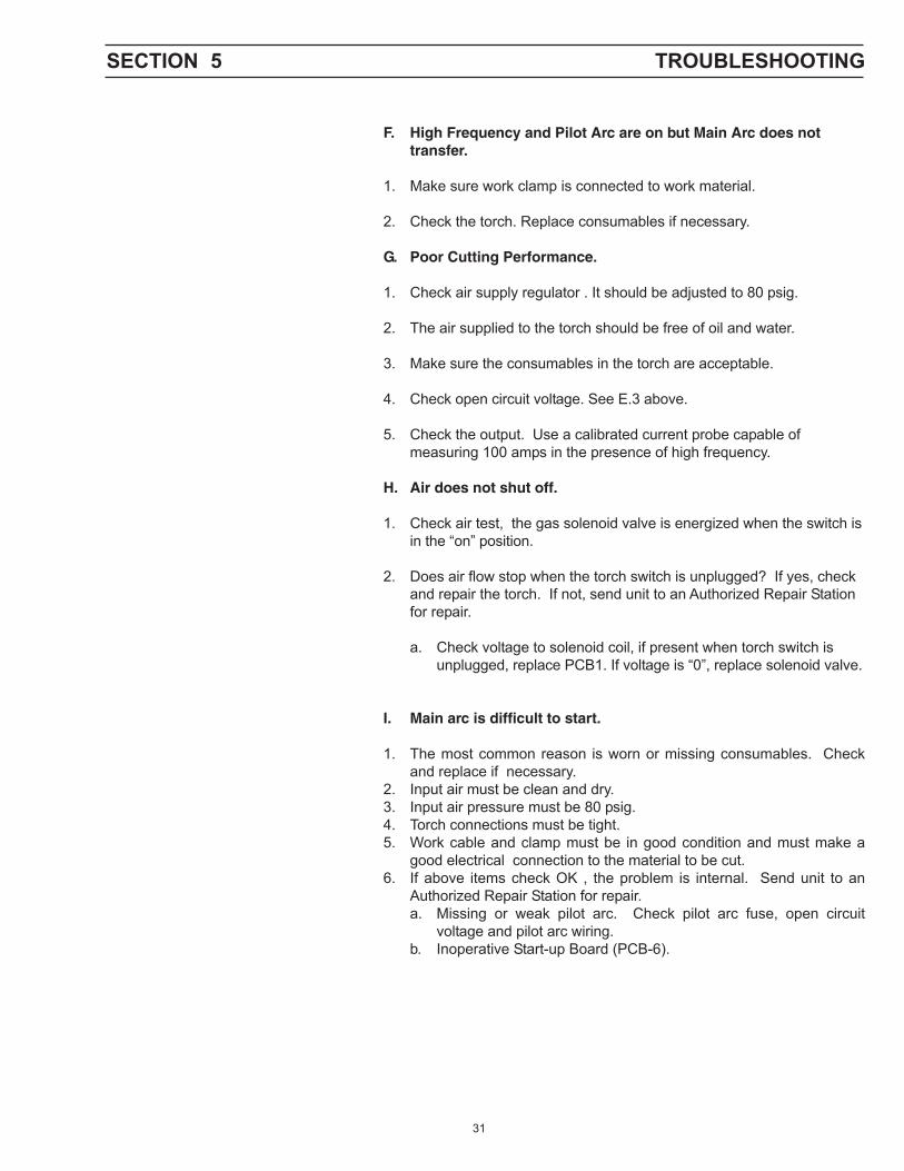
F. High Frequency and Pilot Arc are on but Main Arc does nottransfer.
1. Make sure work clamp is connected to work material.
2. Check the torch. Replace consumables if necessary.
G. Poor Cutting Performance.
1. Check air supply regulator . It should be adjusted to 80 psig.
2. The air supplied to the torch should be free of oil and water.
3. Make sure the consumables in the torch are acceptable.
4. Check open circuit voltage. See E.3 above.
5. Check the output. Use a calibrated current probe capable ofmeasuring 100 amps in the presence of high frequency.
H. Air does not shut off.
1. Check air test, the gas solenoid valve is energized when the switch isin the “on” position.
2. Does air flow stop when the torch switch is unplugged? If yes, checkand repair the torch. If not, send unit to an Authorized Repair Stationfor repair.
a. Check voltage to solenoid coil, if present when torch switch isunplugged, replace PCB1. If voltage is “0”, replace solenoid valve.
I. Main arc is difficult to start.
1. The most common reason is worn or missing consumables. Checkand replace if necessary.
2. Input air must be clean and dry.3. Input air pressure must be 80 psig.4. Torch connections must be tight.5. Work cable and clamp must be in good condition and must make a
good electrical connection to the material to be cut.6. If above items check OK , the problem is internal. Send unit to an
Authorized Repair Station for repair.a. Missing or weak pilot arc. Check pilot arc fuse, open circuit
voltage and pilot arc wiring.b. Inoperative Start-up Board (PCB-6).
SECTION 5 TROUBLESHOOTING

32
SECTION 5 TROUBLESHOOTING
Figure 5.1 IGBT Gating Signal
5.3 REFERENCE VOLTAGE CHECKS
A. Control Board Assembly (PCB1)
1. LED’s
LED- (D9)- Torch SwitchLED- (D4)- Pilot Arc RelayLED- (D1)- Gas Solenoid Valve
2. Voltage Test Points
Tests are made with power on - no arc.
Disable High Frequency by disconnecting blue wire with blacksleeve
TP-1 - Torch trigger signalTP-4 - IGBT’s driving signal - switching frequency = 18.5 KHzTP-5 - IGBT’s driving signal - switching frequency = 18.5 KHzTP-7 - +5 vdcTP-8 - +15 vdcTP-9 - -15 vdcTP-10- Ground
54 µs
13vdc
13vdc
0

33
TORCH SWITCH
OPEN CLOSEGAS SOLENOID VALVE
PREFLOW
FLOW SWITCH CLOSE
FAULT OVERLOAD LIGHT
HF CIRCUIT
PILOT ARC
INVERTER
CUTTING ARC (CURRENT)
5.4SEQUENCE OF OPERATION
A. TRIGGER LOCK “UNLOCK” position
PUSH RELEASE
ENERGIZE
NOTES:
1. When the torch switch is pushed during postflow period, the postflow and preflow times are canceled, and theHF is energized immediately.
2. When the amber fault light comes on, cutting operation should be stopped. The postflow time starts from themoment the torch switch is released.
20 SEC
PostflowOPEN
2 SEC.
SECTION 5 TROUBLESHOOTING

34
SECTION 5 TROUBLESHOOTING
PUSH RELEASE PUSH RELEASETORCH SWITCH
OPEN CLOSE GAS SOLENOID VALVE
CLOSE OPENFLOW SWITCH
FAULT LIGHT
HF CIRCUIT
PILOT ARC
INVERTER
CUTTING ARC (CURRENT)
B. TRIGGER LOCK "LOCK" position
ENERGIZE
NOTES:
1. When the torch switch is pushed during postflow period, the postflow timeis reset, the preflow time is canceled, and the HF is energized immediately.
2. When the red fault light comes on, cutting operation should be stopped.The postflow time starts from the moment the torch switch is released.
3. FAULT light is on during second "turn-off" trigger only. This does not affectperformance in any way.
PREFLOW2 SEC.
20 SEC
Postflow

35
Pow
ercu
t-150
0 Sc
hem
atic
Dia
gram
D-0
5580
0310
8-B

36
SECTION 6 REPLACEMENT PARTS
A. REPLACEMENT PARTS
Replacement Parts are illustrated on the following figures. When orderingreplacement parts, order by part number and part name, as illustrated on thefigure. Always provide the series or serial number of the unit on which theparts will be used. The serial number is stamped on the unit nameplate.
B. ORDERING
To assure proper operation, it is recommended that only genuine ESAB partsand products be used with this equipment. The use of non-ESAB parts mayvoid your warranty.
Replacement parts may be ordered from your ESAB distributor or from:
ESAB Welding & Cutting ProductsAttn: Customer Service Dept.P.O. Box 100545, 411 S. Ebenezer RoadFlorence, SC 29501-0545
Be sure to indicate any special shipping instructions when ordering replace-ment parts.
To order parts by phone, contact ESAB at 1-843-664-5540. Orders may alsobe faxed to 1-800-634-7548. Be sure to indicate any special shipping in-structions when ordering replacement parts.
Refer to the Communication Guide located on the last page of this manualfor a list of customer service phone numbers.

37
SECTION 6 REPLACEMENT PARTS
Item PartNo. Qty. No. Description Symbol
1 1 36107 SW Pwr Disc 600V S12 2 951474 Switch Seal Black3 1 954942 Overlay Front Panel Powercut-15004 1 0558001818 Knob 1.37 Diam5 1 0558002461M Panel Front6 1 0558003001 Work Cable #6 AWG7 1 13733935 Panel Receptacle8 2 0558002780 Foot Plasma Tube9 1 0558002581 Strain Relief Input NPT
10 1 950435 Locknut, 1.00", Conduit Fitting11 1 0558002464M Cover Torch Connection
1
23
4
57
68
9, 10
11
Front View - Powercut-1500

38
Item PartNo. Qty. No. Description Symbol
1 1 21710 Regulator Air Line *808-022 1 21711 Gauge 1.50 *160 PSI WHT CB3 1 0558002446 Switch 40A S24 1 0558003075 Fuse 2A 600VAC, Fast Acting Only F15 1 97W63 Connector Cable Grip6 1 0558003002 Cable Input Power, 10Ft.7 1 951182 Fan 230V 50/60 Hz 233CFM M18 1 0558002994 Finger Guard 1.5MM (.06 IN.)
SECTION 6 REPLACEMENT PARTS
1
Rear View - Powercut-1500
23
4
5
6
7
8

39
SECTION 6 REPLACEMENT PARTS
Internal View - Powercut-1500Lower Left Side
Item PartNo. Qty. No. Description Symbol
1 2 0558002447 Transformer Main T2, T42 4 17721020 RES WWFAHT 25W 1% 20 OHMS R12-153 2 951185 Diode Module FDS 100A 600V D7, D84 2 952252 Transducer Current 100A T5, T75 1 0558002576 Relay SPST 24V w/MAG K26 1 0558002455 Inductor Output L2
1
2 3
4
5
6
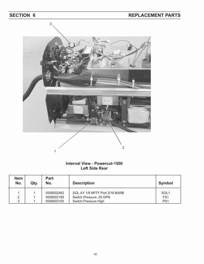
40
SECTION 6 REPLACEMENT PARTS
Internal View - Powercut-1500Left Side Rear
Item PartNo. Qty. No. Description Symbol
1 1 0558002482 SOL AY 1/8 NPTF Port 3/16 BARB SOL12 1 0558002189 Switch Pressure .25 GPN FS13 1 0558003105 Switch Pressure High PS1
12
3

41
SECTION 6 REPLACEMENT PARTS
Item PartNo. Qty. No. Description Symbol
1 1 0558002446 Switch 40A S22 2 0558002435 CAP 3100 UF 450VDC Alum C5, C63 1 36107 SW PWR* Disc 600V S1
12
3
Internal View - Powercut-1500Left Side Sub-Assembly

42
SECTION 6 REPLACEMENT PARTS
Item PartNo. Qty. No. Description Symbol
1 1 0558002434 3PH BR Rect. w/out Thyristor BR12 1 17750050 RES WW 50W 50 OHM R13 2 0558003182 Module Dual IGBT 200A 600V Q2, Q34 2 17750051 RES WW AHNI 50W 3%K 10 OHM R6, R75 4 951161 CAPC Metpoly *20.0***UF 400VDC C11-C146 1 38206 PCB Power PCB57 1 38229 PCB HI Freq PCB2
12
34
567
Internal View - Powercut-1500Right Side

43
SECTION 6 REPLACEMENT PARTS
Item PartNo. Qty. No. Description Symbol
1 4 17712502 RES WW AH** TT *25W *3% 5K OHMs R8 - 112 1 0558002448 Transformer Control T63 1 0558002438 Inductor Input L14 1 0558002449 Transformer Hi Frequency T85 1 38224 PCB IGBT Driver PCB7
12
3
4
Internal View - Powercut-1500Right Side Sub-Assembly
5(Located Under Lip)

44
JP1
JP4
5
1
43
2
Item PartNo. Qty. No. Description Symbol
1 1 38180 PCB Control PCB12 1 952938 SCR 480V 18A Panel MNT Q13 1 38208 PCB SCR Trigger PCB44 1 950710 Switch Thermal 131°F TS25 1 951818 Relay SS 3—32VDC/24—28VAC 25A Q4
Upper Left Side Internal View - Powercut-1500
SECTION 6 REPLACEMENT PARTS

45
SECTION 6 REPLACEMENT PARTS
Internal View - Powercut-1500Front Left Side
Item PartNo. Qty. No. Description Symbol
1 1 38131 PCB Start-up Network PCB62 1 38172 PCB Display PCB3
12

46

47
Instruction Manual Changes
The "A" edition (3/02) of the manual covers the following:
1. Schematic Diagram upgraded from 0558003108 to 0558003108-A.
2. PCB Start-Up Network (P/N 38200) replaced with (P/N 38131) in parts list on page 34.
Revision C = Added P/N 950435 (Locknut) to Replacement Parts Page 37 - 10 / 2003

F15-695-C 10 / 2003
IF YOU DO NOT KNOW WHOM TO CALL
Telephone: (800) ESAB-123/ Fax: (843) 664-4452/ Web:http://www.esab.com
Hours: 7:30 AM to 5:00 PM EST
A. CUSTOMER SERVICE QUESTIONS: Telephone: (800)362-7080 / Fax: (800) 634-7548Order Entry Product Availability Pricing DeliveryOrder Changes Saleable Goods Returns Shipping Information
Hours: 8:00 AM to 7:00 PM EST
B. ENGINEERING SERVICE: Telephone: (843) 664-4416 / Fax : (800) 446-5693Welding Equipment Troubleshooting Hours: 7:30 AM to 5:00 PM ESTWarranty Returns Authorized Repair Stations
C. TECHNICAL SERVICE: Telephone: (800) ESAB-123/ Fax: (843) 664-4452Part Numbers Technical Applications Hours: 8:00 AM to 5:00 PM ESTPerformance Features Technical Specifications Equipment Recommendations
D. LITERATURE REQUESTS: Telephone: (843) 664-5562 / Fax: (843) 664-5548Hours: 7:30 AM to 4:00 PM EST
E. WELDING EQUIPMENT REPAIRS: Telephone: (843) 664-4487 / Fax: (843) 664-5557Repair Estimates Repair Status Hours: 7:30 AM to 3:30 PM EST
F. WELDING EQUIPMENT TRAINING:Telephone: (843)664-4428 / Fax: (843) 679-5864Training School Information and Registrations Hours: 7:30 AM to 4:00 PM EST
G. WELDING PROCESS ASSISTANCE:Telephone: (800) ESAB-123 Hours: 7:30 AM to 4:00 PM EST
H. TECHNICAL ASST. CONSUMABLES:Telephone : (800) 933-7070 Hours: 7:30 AM to 5:00 PM EST
ESAB Welding & Cutting Products, Florence, SC Welding EquipmentCOMMUNICATION GUIDE - CUSTOMER SERVICES