Embed Size (px)
Citation preview

IJIRST –International Journal for Innovative Research in Science & Technology| Volume 2 | Issue 03 | August 2015 ISSN (online): 2349-6010
All rights reserved by www.ijirst.org 82
Power Transmission of AC-DC Supply in a Single
Composite Conductor
P. AjayKumar L. PhaniKumar
PG Student Associate Professor
Department of Electrical and Electronics Engineering Department of Electrical and Electronics Engineering
Narsimha Reddy Engineering College Narsimha Reddy Engineering College
Abstract
A recently proposed concept of simultaneous ac–dc power transmission enables the long extra high-voltage ac lines to be loaded
close to their thermal limits. The conductors are allowed to carry a certain amount of dc current superimposed on usual ac. This
paper gives the feasibility of converting a double circuit ac line into composite ac–dc power transmission line to get the
advantages of parallel ac–dc transmission to improve power angle, stability and damping out oscillations and reduce
transmission line losses and also we can tap the power in rural areas in very least economical basis. The proposed scheme is
digitally simulated with the help of a MATLAB/SIMULINK software package. Simulation results clearly indicate that the
tapping of a small amount of ac power from the composite ac–dc transmission line has a negligible impact on the normal
functioning of the composite ac–dc power transmission system.
Keywords: MATLAB/SIMULINK Simulation, Simultaneous Ac–Dc Power Transmission, Simultaneous AC–DC Power
Transmission
_______________________________________________________________________________________________________
I. INTRODUCTION
In Presently, environmental right-of-way and cost concerns have delayed the construction of a new transmission line, while
demand of electric power has shown steady but geographically uneven growth. The power is often available at locations not
close to the growing load centers but at remote locations. These locations are largely determined by regulatory policies,
environmental acceptability, and the cost of available energy. The wheeling of this available energy through existing long ac
lines to load centers has a certain upper limit due to stability considerations. Techno-economic reasons prevent the tapping of a
small amount of power from HVDC transmission lines. This is considered a major drawback due to the fact that in many
instances, HVDC transmission lines pass over many rural communities that have little or no access to electricity.
In the past, a number of schemes have been proposed for small power tapping from HVDC lines. Most of these schemes use
forced commutated or line commutated inverters to tap off the power from the HVDC system. These schemes inherently
required additional commutation circuitry or local generation which, in turn, leads to the high cost of installations and
operational complications.
Ekstrom and Lamell have proposed a scheme for small power tapping from an HVDC line based on a current source line-
commutated single-phase thyristor bridge, connected in series with the HVDC line. To start the tap operation, a local dc voltage
source is required in this scheme.
The available bulk electric energy can also be wheeled by simultaneous ac-dc power transmission recently proposed by the
authors. In this scheme, the conductors are allowed to carry superimposed dc current along with ac current. The feasibility of
simultaneous ac-dc power transmission has been proved by laboratory modeled experimental verification as well as digital
simulation. Substantial power upgrading has already been demonstrated by converting the EHV ac line into a composite ac-dc
transmission line without any alteration. The transmission angle can be increased up to 800 in a composite ac-dc line without
losing transient stability, which is impossible in a pure EHV ac line.
From this composite ac–dc line, small power tapping is also possible despite the presence of a dc component in it. This paper
proposes a simple scheme of small power transmission of AC-DC supply in single composite conductor. In this study, the
tapping stations are assumed to draw power up to 10% of the total power transfer capability of the composite line. However,
more power tapping is also possible subject to the condition that it is always less than the ac power component.
II. SIMULTANEOUS AC-DC TRANSMISSION LINE:
The main requirements of simultaneous ac-dc transmission line are follows.
The per unit cost of the tap must be strongly constrained (i.e., the fixed cost must be kept as low as possible).
The tap controls should not interfere with the main system (i.e., the tap control system has to be strictly local). Failure
to achieve this leads to a complex control system requirement and, thus, higher cost of hardware.
Power Transmission of AC-DC Supply in a Single Composite Conductor (IJIRST/ Volume 2 / Issue 03/ 016)
All rights reserved by www.ijirst.org 83
Small tap stations having a total rating less than 10% of the main terminal rating have potential applications where
small, remote communities or industries require economic electric power.
A synchronous machine is feeding power to infinite bus via a double circuit, three-phase, 400-KV, 50-Hz, 450-Km AC
transmission line. The 2750-MVA (5 * 550), 24.0-KV synchronous machine is dynamically modeled, a field coil on d-
axis and a damper coil on q-axis, by Park’s equations with the frame of reference based in rotor.
Short interruption of the power supplies should be tolerable at the occurrence of temporary earth faults on the main
simultaneous ac–dc power transmission system. Further, any fault occurring within tapping station and its local AC
network is to be cleared by local CBs.
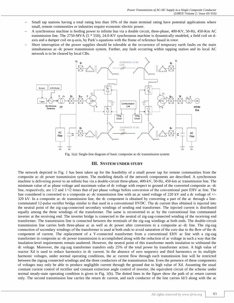
Fig. 1(a): Single-line diagram of basic composite ac-dc transmission system
III. SYSTEM UNDER STUDY
The network depicted in Fig. 1 has been taken up for the feasibility of a small power tap for remote communities from the
composite ac–dc power transmission system. The modeling details of the network components are described. A synchronous
machine is delivering power to an infinite bus via a double-circuit three-phase, 400-kV, 50-Hz, 450-km ac transmission line. The
minimum value of ac phase voltage and maximum value of dc voltage with respect to ground of the converted composite ac–dc
line, respectively, are 1/2 and 1/√2 times that of per phase voltage before conversion of the conventional pure EHV ac line. The
line considered is converted to a composite ac–dc transmission line with an ac rated voltage of 220 kV and a dc voltage of +/-
320 kV. In a composite ac–dc transmission line, the dc component is obtained by converting a part of the ac through a line-
commutated 12-pulse rectifier bridge similar to that used in a conventional HVDC. The dc current thus obtained is injected into
the neutral point of the zig-zag-connected secondary windings of sending end transformer. The injected current is distributed
equally among the three windings of the transformer. The same is reconverted to ac by the conventional line commutated
inverter at the receiving end. The inverter bridge is connected to the neutral of zig-zag-connected winding of the receiving end
transformer. The transmission line is connected between the terminals of the zig-zag windings at both ends. The double-circuit
transmission line carries both three-phase ac as well as dc power after conversion to a composite ac–dc line. The zig-zag
connection of secondary windings of the transformer is used at both ends to avoid saturation of the core due to the flow of the dc
component of current. The replacement of a Y-connected transformer from a conventional EHV ac line with a zig-zag
transformer in composite ac–dc power transmission is accomplished along with the reduction of ac voltage in such a way that the
insulation-level requirements remain unaltered. However, the neutral point of this transformer needs insulation to withstand the
dc voltage. Moreover, the zig-zag transformer transfers only 25% of the total power by transformer action. A high value of
reactor Xd is used to reduce harmonics in dc current. In the absence of zero sequence and third harmonics or its multiple
harmonic voltages, under normal operating conditions, the ac current flow through each transmission line will be restricted
between the zigzag connected windings and the three conductors of the transmission line. Even the presence of these components
of voltages may only be able to produce negligible current through the ground due to high value of Xd. Assuming the usual
constant current control of rectifier and constant extinction angle control of inverter, the equivalent circuit of the scheme under
normal steady-state operating condition is given in Fig. 1(b). The dotted lines in the figure show the path of ac return current
only. The second transmission line carries the return dc current, and each conductor of the line carries Id/3 along with the ac
Power Transmission of AC-DC Supply in a Single Composite Conductor (IJIRST/ Volume 2 / Issue 03/ 016)
All rights reserved by www.ijirst.org 84
current per phase. And are the maximum values of rectifier and inverter side dc voltages and are parameters per phase of each
line. Rcr, Rci are commutating resistances, and, α, γ are firing and extinction angles of rectifier and inverter, respectively.
Neglecting the resistive drops in the line conductors and transformer windings due to dc current, expressions for ac voltage and
current, and for active and reactive powers in terms of A, B, C, and D parameters of each line may be written as
ES=A*ER+B*IR (1)
IS=C*ER+D*IR (2)
PS+JQS= - ES*ER/B*+D*E2S/B* (3)
PR+jQR= ES*ER/B*-A* E2
R/B* (4)
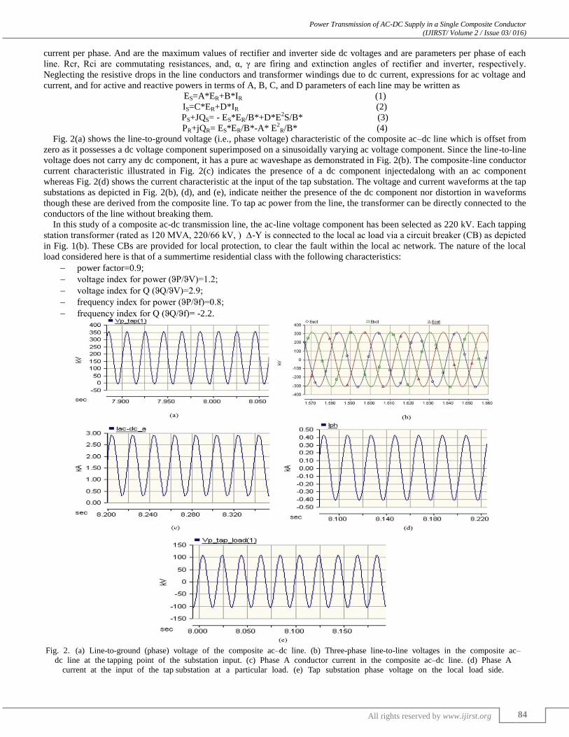
Fig. 2(a) shows the line-to-ground voltage (i.e., phase voltage) characteristic of the composite ac–dc line which is offset from
zero as it possesses a dc voltage component superimposed on a sinusoidally varying ac voltage component. Since the line-to-line
voltage does not carry any dc component, it has a pure ac waveshape as demonstrated in Fig. 2(b). The composite-line conductor
current characteristic illustrated in Fig. 2(c) indicates the presence of a dc component injectedalong with an ac component
whereas Fig. 2(d) shows the current characteristic at the input of the tap substation. The voltage and current waveforms at the tap
substations as depicted in Fig. 2(b), (d), and (e), indicate neither the presence of the dc component nor distortion in waveforms
though these are derived from the composite line. To tap ac power from the line, the transformer can be directly connected to the
conductors of the line without breaking them.
In this study of a composite ac-dc transmission line, the ac-line voltage component has been selected as 220 kV. Each tapping
station transformer (rated as 120 MVA, 220/66 kV, ) ∆-Ү is connected to the local ac load via a circuit breaker (CB) as depicted
in Fig. 1(b). These CBs are provided for local protection, to clear the fault within the local ac network. The nature of the local
load considered here is that of a summertime residential class with the following characteristics:
power factor=0.9;
voltage index for power (ϑP/ϑV)=1.2;
voltage index for Q (ϑQ/ϑV)=2.9;
frequency index for power (ϑP/ϑf)=0.8;
frequency index for Q (ϑQ/ϑf)= -2.2.
Fig. 2. (a) Line-to-ground (phase) voltage of the composite ac–dc line. (b) Three-phase line-to-line voltages in the composite ac–
dc line at the tapping point of the substation input. (c) Phase A conductor current in the composite ac–dc line. (d) Phase A
current at the input of the tap substation at a particular load. (e) Tap substation phase voltage on the local load side.

Power Transmission of AC-DC Supply in a Single Composite Conductor (IJIRST/ Volume 2 / Issue 03/ 016)
All rights reserved by www.ijirst.org 85
Fig. 3: (a) Combined AC-DC Current. (b) Tap power (Pt1), receiving end (Pac) ac power, sending end (Pacs) ac power, and receiving end
dc power (Pinvdc). (c) AC (Pac), dc (Pinvdc), and total (P_tranfer) power transfer at the receiving end. (d) Qrecdc and Qinvdc reactive power
drawn by the rectifier and inverter. Qac-send and Qac-Rend reactive power drawn by the lines from each end. (e) Rectifier (Vdr) and inverter
(Vdi) dc voltages. (f) Transmission angle (Transm_Angle).

Power Transmission of AC-DC Supply in a Single Composite Conductor (IJIRST/ Volume 2 / Issue 03/ 016)
All rights reserved by www.ijirst.org 86
Fig. 4(a): Tap power (Pt1), receiving end (Pac) ac powers, sending end (Pacs) ac power, and receiving end dc power (Pinvdc). (b) AC (Pac), dc
(Pinvdc), and total (P_tranfer) power transfer at the receiving end. (c) Qrecdc, Qinvdc reactive power drawn by the rectifier and inverter. Qac-
send and Qac-Rend reactive power drawn by the line from each end. (d) Rectifier (Vdr) and inverter (Vdi) dc voltages.

Power Transmission of AC-DC Supply in a Single Composite Conductor (IJIRST/ Volume 2 / Issue 03/ 016)
All rights reserved by www.ijirst.org 87
Fig. 5: (a) Tap power (Pt1), receiving end (Pac) ac power, sending end (Pacs) ac power, and receiving end dc power (Pinvdc). (b) Line voltage
variations acrossthe CB’s input. (c) Transformer input line currents variations measured at the CB’s input. (d) Transmission angle
(Transm_Angle). (e) Sending (Vs_rms) and receiving (Vr_rms) end bus voltages. (f) Rectifier (AOR) and inverter (Aoi) firing angle order. (g)
Rectifier (Vdr) and inverter (Vdi) dc voltages. (h) Generator’sspeed deviation (delta omega). (i) Generator’s active (Pg) and reactive (Qg)
power output.

Power Transmission of AC-DC Supply in a Single Composite Conductor (IJIRST/ Volume 2 / Issue 03/ 016)
All rights reserved by www.ijirst.org 88
Fig. 6(a): Tap power (Pt1), receiving end (Pac) ac power, sending end (Pacs) ac power, and receiving end dc power (Pinvdc). (b) Line voltage
variations across the CB’s input. (c) Transformer input line currents variations measured at the CB’s input. (d) Sending (Vs_rms) and receiving-
end (Vr_rms) bus voltages. (e) Rectifier (AOR) and inverter (Aoi) firing-angle order. (f) Rectifier (Vdr) and inverter (Vdi) dc voltages. (g)
Generator’s speed deviation (delta omega). (h) Generator’s active (Pg) and reactive (Qg) power output.

Power Transmission of AC-DC Supply in a Single Composite Conductor (IJIRST/ Volume 2 / Issue 03/ 016)
All rights reserved by www.ijirst.org 89
IV. DIGITAL SIMULATION OF THE PROPOSED SCHEME
In order to examine the feasibility of the proposed scheme for power transmission of AC-DC supply in single conductor and to
observe the performance of the composite ac-dc power transmission system under various operating conditions, the digital
simulation software packages both in MATLAB and PSCAD/EMTDC was used.
V. CONCLUSION
The feasibility of tapping a small amount of power to feed remotely located communities in the same simple way as tapping in
the case of an EHV ac line is demonstrated for the composite ac–dc transmission system. It is also economical compared to
complicated methods of tapping from the HVDC line. The results clearly demonstrate that the tapping of a small amount of ac
component of power from the composite ac–dc transmission line has a negligible impact on the dc power transfer.
ACKNOWLEDGEMENT
I take this opportunity to express gratitude to all of the Department faculty members for their help and support. I also thank my
parents for the their encouragement, support and attention.
REFERENCES
[1] L. Chetty, N. M. Ijumba, and A. C. Britten, “Parallel-cascaded tapping station,” in Proc. IEEE Int. Conf. Power System Technology, 2004, pp.1674–1878.
[2] H. Rahman and B. H. Khan, “Power upgrading of transmission line by combining ac-dc transmission,” IEEE Trans. Power Syst., vol. 22, no.1, pp. 459–466, Feb. 2007.
[3] A. Ekstrom and P. Lamell, “HVDC tapping station: Power tapping from a dc transmission line to a local ac network,” in Proc. AC-DCConf., London, U.K., 1991, pp. 126–131.
[4] Task force on Small HVDCTaps, Working Group, “Integration of small taps into (existing) HVDC links,” IEEE Trans. Power Del., vol. 10, no. 3, pp.
1699–1706, Jul. 1995. [5] M. R. Aghaebrahimi and R. W. Menzies, “Small power tapping from HVDC transmission system: A novel approach,” IEEE Trans. Power Del., vol. 12, no.
4, pp. 1698–1703, Oct. 1997.
[6] PSCAD/EMTDC, User’s Guide Manitoba-HVDC Research Centre. Winnipeg, MB, Canada, Jan. 2003. [7] P. S. Kundur, Power System Stability and Control. New York: McGraw-Hill, 1994.