Embed Size (px)
Citation preview

Power SystemProtection
S.A.Soman
Review of PerunitCalculationand Modelingof Apparatus
ModelingAspects ofStaticApparatusModelling ofTransmission Line
Modeling of MutuallyCoupled Lines
Modeling ofTransformer
Modeling ofSynchronousMachineSequence Modelingof InductionMachines
Modeling of ElectricalUtility Systems
Load Modeling
Modeling of SeriesCapacitors
SequenceNetworkAdmittanceMatrixFormulation
Short CircuitAnalysisUsingSequenceComponentsCalculation of ShortCircuit MVA
Power System Protection
S.A.Soman
Department of Electrical EngineeringIIT Bombay
Sequence Modeling of Power Apparatus

Power SystemProtection
S.A.Soman
Review of PerunitCalculationand Modelingof Apparatus
ModelingAspects ofStaticApparatusModelling ofTransmission Line
Modeling of MutuallyCoupled Lines
Modeling ofTransformer
Modeling ofSynchronousMachineSequence Modelingof InductionMachines
Modeling of ElectricalUtility Systems
Load Modeling
Modeling of SeriesCapacitors
SequenceNetworkAdmittanceMatrixFormulation
Short CircuitAnalysisUsingSequenceComponentsCalculation of ShortCircuit MVA
Sequence Modeling of Power Apparatus
1 Review of Per unit Calculation and Modeling ofApparatus
2 Modeling Aspects of Static ApparatusModelling of Transmission LineModeling of Mutually Coupled LinesModeling of Transformer
3 Modeling of Synchronous MachineSequence Modeling of Induction MachinesModeling of Electrical Utility Systems
Load ModelingModeling of Series Capacitors
4 Sequence Network Admittance Matrix Formulation
5 Short Circuit Analysis Using Sequence ComponentsCalculation of Short Circuit MVA

Power SystemProtection
S.A.Soman
Review of PerunitCalculationand Modelingof Apparatus
ModelingAspects ofStaticApparatusModelling ofTransmission Line
Modeling of MutuallyCoupled Lines
Modeling ofTransformer
Modeling ofSynchronousMachineSequence Modelingof InductionMachines
Modeling of ElectricalUtility Systems
Load Modeling
Modeling of SeriesCapacitors
SequenceNetworkAdmittanceMatrixFormulation
Short CircuitAnalysisUsingSequenceComponentsCalculation of ShortCircuit MVA
Objectives
ObjectivesPer unit calculation and its advantages.Modeling aspects of static apparatus like transmissionline and transformers.Modeling of rotating machine like synchronousmachines and induction machinesFormation of sequence admittance matrices.Evaluation of Thevenin’s equivalent.

Power SystemProtection
S.A.Soman
Review of PerunitCalculationand Modelingof Apparatus
ModelingAspects ofStaticApparatusModelling ofTransmission Line
Modeling of MutuallyCoupled Lines
Modeling ofTransformer
Modeling ofSynchronousMachineSequence Modelingof InductionMachines
Modeling of ElectricalUtility Systems
Load Modeling
Modeling of SeriesCapacitors
SequenceNetworkAdmittanceMatrixFormulation
Short CircuitAnalysisUsingSequenceComponentsCalculation of ShortCircuit MVA
Review of Per unit Calculation and Modeling ofApparatus
Per Unit Quantity =Actual QuantityBase Quantity
Base Current(Amp) =Base(KVA)× 1000√
3 Base Volts
Base Impedence(Ohm) =Base(Volt)√
3 Base Current
ZP.U =Actual Impedance(Ohm)× Base(MVA in 3 phase)
(Base(Line Voltage in kV))2

Power SystemProtection
S.A.Soman
Review of PerunitCalculationand Modelingof Apparatus
ModelingAspects ofStaticApparatusModelling ofTransmission Line
Modeling of MutuallyCoupled Lines
Modeling ofTransformer
Modeling ofSynchronousMachineSequence Modelingof InductionMachines
Modeling of ElectricalUtility Systems
Load Modeling
Modeling of SeriesCapacitors
SequenceNetworkAdmittanceMatrixFormulation
Short CircuitAnalysisUsingSequenceComponentsCalculation of ShortCircuit MVA
Advantages of P.U computation
1 Manufactures usually provide equipment data withname plate rating as base.
2 Range for acceptable % or p.u. values can be easilyfixed.
3 Especially useful in networks with multiple voltagelevels interconnected through transformers.
4 P.U impedance of transformer is independent of the kVbase.
5 Standard base conversion (scaling with MVA Base)formulae are available.

Power SystemProtection
S.A.Soman
Review of PerunitCalculationand Modelingof Apparatus
ModelingAspects ofStaticApparatusModelling ofTransmission Line
Modeling of MutuallyCoupled Lines
Modeling ofTransformer
Modeling ofSynchronousMachineSequence Modelingof InductionMachines
Modeling of ElectricalUtility Systems
Load Modeling
Modeling of SeriesCapacitors
SequenceNetworkAdmittanceMatrixFormulation
Short CircuitAnalysisUsingSequenceComponentsCalculation of ShortCircuit MVA
Sequence Modeling of Power Apparatus
1 Review of Per unit Calculation and Modeling ofApparatus
2 Modeling Aspects of Static ApparatusModelling of Transmission LineModeling of Mutually Coupled LinesModeling of Transformer
3 Modeling of Synchronous MachineSequence Modeling of Induction MachinesModeling of Electrical Utility Systems
Load ModelingModeling of Series Capacitors
4 Sequence Network Admittance Matrix Formulation
5 Short Circuit Analysis Using Sequence ComponentsCalculation of Short Circuit MVA

Power SystemProtection
S.A.Soman
Review of PerunitCalculationand Modelingof Apparatus
ModelingAspects ofStaticApparatusModelling ofTransmission Line
Modeling of MutuallyCoupled Lines
Modeling ofTransformer
Modeling ofSynchronousMachineSequence Modelingof InductionMachines
Modeling of ElectricalUtility Systems
Load Modeling
Modeling of SeriesCapacitors
SequenceNetworkAdmittanceMatrixFormulation
Short CircuitAnalysisUsingSequenceComponentsCalculation of ShortCircuit MVA
Modelling of Transmission Line

Power SystemProtection
S.A.Soman
Review of PerunitCalculationand Modelingof Apparatus
ModelingAspects ofStaticApparatusModelling ofTransmission Line
Modeling of MutuallyCoupled Lines
Modeling ofTransformer
Modeling ofSynchronousMachineSequence Modelingof InductionMachines
Modeling of ElectricalUtility Systems
Load Modeling
Modeling of SeriesCapacitors
SequenceNetworkAdmittanceMatrixFormulation
Short CircuitAnalysisUsingSequenceComponentsCalculation of ShortCircuit MVA
Modelling of Transmission Line contd..
∆Va
∆Vb
∆Vc
=
Zs Zm Zm
Zm Zs Zm
Zm Zm Zs
IaIbIc
Applying sequence transformation, we get∆V1 = Z1I1, ∆V2 = Z2I2 and ∆V3 = Z3I3where Z1 = Z2 = Zs − Zm and Z0 = Zs + 2Zm
Thus, for a transposed transmission line, the positiveand negative sequence impedances are equal. Acommonly used approximation for Z0 is to assume it tobe three times Z1.

Power SystemProtection
S.A.Soman
Review of PerunitCalculationand Modelingof Apparatus
ModelingAspects ofStaticApparatusModelling ofTransmission Line
Modeling of MutuallyCoupled Lines
Modeling ofTransformer
Modeling ofSynchronousMachineSequence Modelingof InductionMachines
Modeling of ElectricalUtility Systems
Load Modeling
Modeling of SeriesCapacitors
SequenceNetworkAdmittanceMatrixFormulation
Short CircuitAnalysisUsingSequenceComponentsCalculation of ShortCircuit MVA
Sequence Modeling of Power Apparatus
1 Review of Per unit Calculation and Modeling ofApparatus
2 Modeling Aspects of Static ApparatusModelling of Transmission LineModeling of Mutually Coupled LinesModeling of Transformer
3 Modeling of Synchronous MachineSequence Modeling of Induction MachinesModeling of Electrical Utility Systems
Load ModelingModeling of Series Capacitors
4 Sequence Network Admittance Matrix Formulation
5 Short Circuit Analysis Using Sequence ComponentsCalculation of Short Circuit MVA

Power SystemProtection
S.A.Soman
Review of PerunitCalculationand Modelingof Apparatus
ModelingAspects ofStaticApparatusModelling ofTransmission Line
Modeling of MutuallyCoupled Lines
Modeling ofTransformer
Modeling ofSynchronousMachineSequence Modelingof InductionMachines
Modeling of ElectricalUtility Systems
Load Modeling
Modeling of SeriesCapacitors
SequenceNetworkAdmittanceMatrixFormulation
Short CircuitAnalysisUsingSequenceComponentsCalculation of ShortCircuit MVA
Modeling of Mutually Coupled Lines
Ampere‘s law∮
~H.~dl = inet .
i+net = i+a (t) + i+b (t) + i+c (t) = 0
i−net = i−a (t) + i−b (t) + i−c (t) = 0
i+net = I0Conlusion: Mutual coupling exhibits only in zero sequencenetworks.

Power SystemProtection
S.A.Soman
Review of PerunitCalculationand Modelingof Apparatus
ModelingAspects ofStaticApparatusModelling ofTransmission Line
Modeling of MutuallyCoupled Lines
Modeling ofTransformer
Modeling ofSynchronousMachineSequence Modelingof InductionMachines
Modeling of ElectricalUtility Systems
Load Modeling
Modeling of SeriesCapacitors
SequenceNetworkAdmittanceMatrixFormulation
Short CircuitAnalysisUsingSequenceComponentsCalculation of ShortCircuit MVA
Mathematical Explaination
∆va1
∆vb1
∆vc1
=
Zs Zm Zm
Zm Zs Zm
Zm Zm Zs
Ia1
Ib1
Ic1
+jα
1 1 11 1 11 1 1
Ia2
Ib2
Ic2
Applying sequence transformation we will get
∆v01
∆v11
∆v11
=
Zs + 2Zm
Zs−Zm
Zs − Zm
I01
I21
I21
+j
3α 0 00 0 00 0 0
I02
I12
I22

Power SystemProtection
S.A.Soman
Review of PerunitCalculationand Modelingof Apparatus
ModelingAspects ofStaticApparatusModelling ofTransmission Line
Modeling of MutuallyCoupled Lines
Modeling ofTransformer
Modeling ofSynchronousMachineSequence Modelingof InductionMachines
Modeling of ElectricalUtility Systems
Load Modeling
Modeling of SeriesCapacitors
SequenceNetworkAdmittanceMatrixFormulation
Short CircuitAnalysisUsingSequenceComponentsCalculation of ShortCircuit MVA
Modeling of Ground
+ve sequence circuit, lground = 0, resistance/impenaceof ground or neutral wire plays no role. Hence groundfor +ve sequence circuit is equipotential surface.
Same Conclusion can be drawn for -ve sequencecurrent.
For zero sequence current, ground potential or drop inthe neutral conductor is not zero. It (arrests) the voltageprofile.
Usually, this drop orequivalent impedance is lumpedwith apparatus impedance to creates a equipotentialground plane.

Power SystemProtection
S.A.Soman
Review of PerunitCalculationand Modelingof Apparatus
ModelingAspects ofStaticApparatusModelling ofTransmission Line
Modeling of MutuallyCoupled Lines
Modeling ofTransformer
Modeling ofSynchronousMachineSequence Modelingof InductionMachines
Modeling of ElectricalUtility Systems
Load Modeling
Modeling of SeriesCapacitors
SequenceNetworkAdmittanceMatrixFormulation
Short CircuitAnalysisUsingSequenceComponentsCalculation of ShortCircuit MVA
Sequence Modeling of Power Apparatus
1 Review of Per unit Calculation and Modeling ofApparatus
2 Modeling Aspects of Static ApparatusModelling of Transmission LineModeling of Mutually Coupled LinesModeling of Transformer
3 Modeling of Synchronous MachineSequence Modeling of Induction MachinesModeling of Electrical Utility Systems
Load ModelingModeling of Series Capacitors
4 Sequence Network Admittance Matrix Formulation
5 Short Circuit Analysis Using Sequence ComponentsCalculation of Short Circuit MVA

Power SystemProtection
S.A.Soman
Review of PerunitCalculationand Modelingof Apparatus
ModelingAspects ofStaticApparatusModelling ofTransmission Line
Modeling of MutuallyCoupled Lines
Modeling ofTransformer
Modeling ofSynchronousMachineSequence Modelingof InductionMachines
Modeling of ElectricalUtility Systems
Load Modeling
Modeling of SeriesCapacitors
SequenceNetworkAdmittanceMatrixFormulation
Short CircuitAnalysisUsingSequenceComponentsCalculation of ShortCircuit MVA
Modeling of Core Type Transformer
Modeling of +ve and -ve sequence impedance isstaright forward - (Equation) net leakage impedance inp.uZero sequence modeling
~φa + ~φb + ~φc = 0 [by KCL]Hence φ0 = 0Practically, zero sequence flux leaks through tankcreats heating. Tank is not (saturates)Not used in unbalanced system (e.g. distribution)X0 –negligible!

Power SystemProtection
S.A.Soman
Review of PerunitCalculationand Modelingof Apparatus
ModelingAspects ofStaticApparatusModelling ofTransmission Line
Modeling of MutuallyCoupled Lines
Modeling ofTransformer
Modeling ofSynchronousMachineSequence Modelingof InductionMachines
Modeling of ElectricalUtility Systems
Load Modeling
Modeling of SeriesCapacitors
SequenceNetworkAdmittanceMatrixFormulation
Short CircuitAnalysisUsingSequenceComponentsCalculation of ShortCircuit MVA
Modeling of Shell Type Transformer
+ve and -ve sequence impedance = leakageimpedanceZero sequence impedance
Low reluctance to zero sequence fluxHigh impedance

Power SystemProtection
S.A.Soman
Review of PerunitCalculationand Modelingof Apparatus
ModelingAspects ofStaticApparatusModelling ofTransmission Line
Modeling of MutuallyCoupled Lines
Modeling ofTransformer
Modeling ofSynchronousMachineSequence Modelingof InductionMachines
Modeling of ElectricalUtility Systems
Load Modeling
Modeling of SeriesCapacitors
SequenceNetworkAdmittanceMatrixFormulation
Short CircuitAnalysisUsingSequenceComponentsCalculation of ShortCircuit MVA
Modeling of Bank of 1 φ transformer
+ve seq impedance = -ve seq imp = zero sequenceimpedanceRole of circuit interconnections on + - and zero seqcircuits of transformers+, -ve sequence cirduits, staright forward,zero sequence circuit
In delta winding zero sequence currents are exists
in star-ungrounded with I0 = 0 i.e. leads to o.c

Power SystemProtection
S.A.Soman
Review of PerunitCalculationand Modelingof Apparatus
ModelingAspects ofStaticApparatusModelling ofTransmission Line
Modeling of MutuallyCoupled Lines
Modeling ofTransformer
Modeling ofSynchronousMachineSequence Modelingof InductionMachines
Modeling of ElectricalUtility Systems
Load Modeling
Modeling of SeriesCapacitors
SequenceNetworkAdmittanceMatrixFormulation
Short CircuitAnalysisUsingSequenceComponentsCalculation of ShortCircuit MVA
Modeling of Transformer contd..

Power SystemProtection
S.A.Soman
Review of PerunitCalculationand Modelingof Apparatus
ModelingAspects ofStaticApparatusModelling ofTransmission Line
Modeling of MutuallyCoupled Lines
Modeling ofTransformer
Modeling ofSynchronousMachineSequence Modelingof InductionMachines
Modeling of ElectricalUtility Systems
Load Modeling
Modeling of SeriesCapacitors
SequenceNetworkAdmittanceMatrixFormulation
Short CircuitAnalysisUsingSequenceComponentsCalculation of ShortCircuit MVA
Modeling of Synchronous Machine
The subtransient reactance X′′
d determines the currentduring the first cycle after fault occurs.
In about 0.1sec, reactance increases to transientreactance X
′
d .
In about 0.5sec to 2sec reactance increases to Xd , thesynchronous reactance; this is the value thatdetermines the current flow after a steady statecondition is reached.

Power SystemProtection
S.A.Soman
Review of PerunitCalculationand Modelingof Apparatus
ModelingAspects ofStaticApparatusModelling ofTransmission Line
Modeling of MutuallyCoupled Lines
Modeling ofTransformer
Modeling ofSynchronousMachineSequence Modelingof InductionMachines
Modeling of ElectricalUtility Systems
Load Modeling
Modeling of SeriesCapacitors
SequenceNetworkAdmittanceMatrixFormulation
Short CircuitAnalysisUsingSequenceComponentsCalculation of ShortCircuit MVA
Modeling of Synchronous Machine
During a fault, motor acts as a generator to supply faultcurrent. The rotor carrying the field winding is driven by theinertia of the rotor and load. Stator excitation is reduced dueto drop in voltage. The fault current diminishes as the rotordecelerates. The generator equivalent circuit is used forsynchronous motor. The constant driving voltage and threereactance X
′′
d , X′
d , and Xd are used to establish the currentvalues at three points in time. Synchronous condensers canbe treated in same manner as synchronous motors.

Power SystemProtection
S.A.Soman
Review of PerunitCalculationand Modelingof Apparatus
ModelingAspects ofStaticApparatusModelling ofTransmission Line
Modeling of MutuallyCoupled Lines
Modeling ofTransformer
Modeling ofSynchronousMachineSequence Modelingof InductionMachines
Modeling of ElectricalUtility Systems
Load Modeling
Modeling of SeriesCapacitors
SequenceNetworkAdmittanceMatrixFormulation
Short CircuitAnalysisUsingSequenceComponentsCalculation of ShortCircuit MVA
Negative sequence Impedance of SynchronousMachines
For a synchronous machine, positive and negativesequence impedances cannot be equal.
Hence, double frequency emf and currents are inducedin rotor.
Negative sequence impedance is 70-95% ofsubtransient reactance.

Power SystemProtection
S.A.Soman
Review of PerunitCalculationand Modelingof Apparatus
ModelingAspects ofStaticApparatusModelling ofTransmission Line
Modeling of MutuallyCoupled Lines
Modeling ofTransformer
Modeling ofSynchronousMachineSequence Modelingof InductionMachines
Modeling of ElectricalUtility Systems
Load Modeling
Modeling of SeriesCapacitors
SequenceNetworkAdmittanceMatrixFormulation
Short CircuitAnalysisUsingSequenceComponentsCalculation of ShortCircuit MVA
Zero Sequence Impedance of SynchronousMachines
Zero Sequence currents cannot create rotating mmf. Infact, with sinusoidally distributed three phase windings,the net flux at any point in the air gap is zero.
Hence, zero sequence impedance is only a small %(0.1-0.7) of the positive sequence impedances
Since synchronous machines only generate positivesequence voltage, the internal voltages used withnegative sequence and zero sequence networks arezero.
If Y point is grounded through impedance Zg , then 3Zg
will have to be added to zero sequence impedance ofgenerator.

Power SystemProtection
S.A.Soman
Review of PerunitCalculationand Modelingof Apparatus
ModelingAspects ofStaticApparatusModelling ofTransmission Line
Modeling of MutuallyCoupled Lines
Modeling ofTransformer
Modeling ofSynchronousMachineSequence Modelingof InductionMachines
Modeling of ElectricalUtility Systems
Load Modeling
Modeling of SeriesCapacitors
SequenceNetworkAdmittanceMatrixFormulation
Short CircuitAnalysisUsingSequenceComponentsCalculation of ShortCircuit MVA
Sequence Modeling of Power Apparatus
1 Review of Per unit Calculation and Modeling ofApparatus
2 Modeling Aspects of Static ApparatusModelling of Transmission LineModeling of Mutually Coupled LinesModeling of Transformer
3 Modeling of Synchronous MachineSequence Modeling of Induction MachinesModeling of Electrical Utility Systems
Load ModelingModeling of Series Capacitors
4 Sequence Network Admittance Matrix Formulation
5 Short Circuit Analysis Using Sequence ComponentsCalculation of Short Circuit MVA
Power SystemProtection
S.A.Soman
Review of PerunitCalculationand Modelingof Apparatus
ModelingAspects ofStaticApparatusModelling ofTransmission Line
Modeling of MutuallyCoupled Lines
Modeling ofTransformer
Modeling ofSynchronousMachineSequence Modelingof InductionMachines
Modeling of ElectricalUtility Systems
Load Modeling
Modeling of SeriesCapacitors
SequenceNetworkAdmittanceMatrixFormulation
Short CircuitAnalysisUsingSequenceComponentsCalculation of ShortCircuit MVA
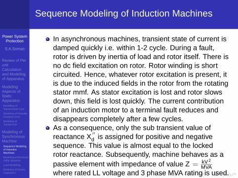
Sequence Modeling of Induction Machines
In asynchronous machines, transient state of current isdamped quickly i.e. within 1-2 cycle. During a fault,rotor is driven by inertia of load and rotor itself. There isno dc field excitation on rotor. Rotor winding is shortcircuited. Hence, whatever rotor excitation is present, itis due to the induced fields in the rotor from the rotatingstator mmf. As stator excitation is lost and rotor slowsdown, this field is lost quickly. The current contributionof an induction motor to a terminal fault reduces anddisappears completely after a few cycles.As a consequence, only the sub transient value ofreactance X
′′
d is assigned for positive and negativesequence. This value is almost equal to the lockedrotor reactance. Subsequently, machine behaves as apassive element with impedance of value Z = kV 2
MVAwhere rated LL voltage and 3 phase MVA rating is used.Zero Sequence modeling can be treated in similar linesas synchronous machines because rotor plays nosignificant role.For fault calculations an induction generator can betreated as an induction motor.

Power SystemProtection
S.A.Soman
Review of PerunitCalculationand Modelingof Apparatus
ModelingAspects ofStaticApparatusModelling ofTransmission Line
Modeling of MutuallyCoupled Lines
Modeling ofTransformer
Modeling ofSynchronousMachineSequence Modelingof InductionMachines
Modeling of ElectricalUtility Systems
Load Modeling
Modeling of SeriesCapacitors
SequenceNetworkAdmittanceMatrixFormulation
Short CircuitAnalysisUsingSequenceComponentsCalculation of ShortCircuit MVA
Sequence Modeling of Power Apparatus
1 Review of Per unit Calculation and Modeling ofApparatus
2 Modeling Aspects of Static ApparatusModelling of Transmission LineModeling of Mutually Coupled LinesModeling of Transformer
3 Modeling of Synchronous MachineSequence Modeling of Induction MachinesModeling of Electrical Utility Systems
Load ModelingModeling of Series Capacitors
4 Sequence Network Admittance Matrix Formulation
5 Short Circuit Analysis Using Sequence ComponentsCalculation of Short Circuit MVA

Power SystemProtection
S.A.Soman
Review of PerunitCalculationand Modelingof Apparatus
ModelingAspects ofStaticApparatusModelling ofTransmission Line
Modeling of MutuallyCoupled Lines
Modeling ofTransformer
Modeling ofSynchronousMachineSequence Modelingof InductionMachines
Modeling of ElectricalUtility Systems
Load Modeling
Modeling of SeriesCapacitors
SequenceNetworkAdmittanceMatrixFormulation
Short CircuitAnalysisUsingSequenceComponentsCalculation of ShortCircuit MVA
Modeling of Electrical Utility Systems
The generator equivalent circuit can be used to represent autility system. Usually, the utility generators are remote fromthe industrial plant. The current contributed to a fault in theremote plant appears to be merely a small increase in loadto the very large central station generators, and this currentcontribution tends to remain constant. Hence, it isrepresented at the plant by single valued equivalentimpedance referred to the point of connection.

Power SystemProtection
S.A.Soman
Review of PerunitCalculationand Modelingof Apparatus
ModelingAspects ofStaticApparatusModelling ofTransmission Line
Modeling of MutuallyCoupled Lines
Modeling ofTransformer
Modeling ofSynchronousMachineSequence Modelingof InductionMachines
Modeling of ElectricalUtility Systems
Load Modeling
Modeling of SeriesCapacitors
SequenceNetworkAdmittanceMatrixFormulation
Short CircuitAnalysisUsingSequenceComponentsCalculation of ShortCircuit MVA
Sequence Modeling of Power Apparatus
1 Review of Per unit Calculation and Modeling ofApparatus
2 Modeling Aspects of Static ApparatusModelling of Transmission LineModeling of Mutually Coupled LinesModeling of Transformer
3 Modeling of Synchronous MachineSequence Modeling of Induction MachinesModeling of Electrical Utility Systems
Load ModelingModeling of Series Capacitors
4 Sequence Network Admittance Matrix Formulation
5 Short Circuit Analysis Using Sequence ComponentsCalculation of Short Circuit MVA

Power SystemProtection
S.A.Soman
Review of PerunitCalculationand Modelingof Apparatus
ModelingAspects ofStaticApparatusModelling ofTransmission Line
Modeling of MutuallyCoupled Lines
Modeling ofTransformer
Modeling ofSynchronousMachineSequence Modelingof InductionMachines
Modeling of ElectricalUtility Systems
Load Modeling
Modeling of SeriesCapacitors
SequenceNetworkAdmittanceMatrixFormulation
Short CircuitAnalysisUsingSequenceComponentsCalculation of ShortCircuit MVA
Load Modeling
One approximate way of accounting prefault load flowcondition in short circuit analysis associated withtransmission system is to model load as positive sequenceshunt impedance.
V 1
I1 =|V 2
i
(Pi − jQi)
The shunt load impedances are added into diagonal of Y oldbus.
Power SystemProtection
S.A.Soman
Review of PerunitCalculationand Modelingof Apparatus
ModelingAspects ofStaticApparatusModelling ofTransmission Line
Modeling of MutuallyCoupled Lines
Modeling ofTransformer
Modeling ofSynchronousMachineSequence Modelingof InductionMachines
Modeling of ElectricalUtility Systems
Load Modeling
Modeling of SeriesCapacitors
SequenceNetworkAdmittanceMatrixFormulation
Short CircuitAnalysisUsingSequenceComponentsCalculation of ShortCircuit MVA
Sequence Modeling of Power Apparatus
1 Review of Per unit Calculation and Modeling ofApparatus
2 Modeling Aspects of Static ApparatusModelling of Transmission LineModeling of Mutually Coupled LinesModeling of Transformer
3 Modeling of Synchronous MachineSequence Modeling of Induction MachinesModeling of Electrical Utility Systems
Load ModelingModeling of Series Capacitors
4 Sequence Network Admittance Matrix Formulation
5 Short Circuit Analysis Using Sequence ComponentsCalculation of Short Circuit MVA

Power SystemProtection
S.A.Soman
Review of PerunitCalculationand Modelingof Apparatus
ModelingAspects ofStaticApparatusModelling ofTransmission Line
Modeling of MutuallyCoupled Lines
Modeling ofTransformer
Modeling ofSynchronousMachineSequence Modelingof InductionMachines
Modeling of ElectricalUtility Systems
Load Modeling
Modeling of SeriesCapacitors
SequenceNetworkAdmittanceMatrixFormulation
Short CircuitAnalysisUsingSequenceComponentsCalculation of ShortCircuit MVA
Modeling of Series Capacitors
Power SystemProtection
S.A.Soman
Review of PerunitCalculationand Modelingof Apparatus
ModelingAspects ofStaticApparatusModelling ofTransmission Line
Modeling of MutuallyCoupled Lines
Modeling ofTransformer
Modeling ofSynchronousMachineSequence Modelingof InductionMachines
Modeling of ElectricalUtility Systems
Load Modeling
Modeling of SeriesCapacitors
SequenceNetworkAdmittanceMatrixFormulation
Short CircuitAnalysisUsingSequenceComponentsCalculation of ShortCircuit MVA
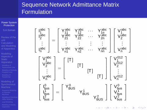
Sequence Network Admittance MatrixFormulation
Iabc1
Iabc2...
Iabcn
=
Y abc
11 Y abc12 · · · Y abc
1nY abc
21 Y abc22 · · · Y abc
2n...
......
...Y abc
n1 Y abcn2 · · · Y abc
nn
V abc1
V abc2...
V abcn
V abc1
V abc2...
V abcn
=
[T ]
[T ][T ]
[T ]
V 0121
V 0122...
V 012n
I0
busI1bus
I2bus
=
Y 0BUS
Y 1BUS
Y 2BUS
V 0bus
V 1bus
V 2bus
Power SystemProtection
S.A.Soman
Review of PerunitCalculationand Modelingof Apparatus
ModelingAspects ofStaticApparatusModelling ofTransmission Line
Modeling of MutuallyCoupled Lines
Modeling ofTransformer
Modeling ofSynchronousMachineSequence Modelingof InductionMachines
Modeling of ElectricalUtility Systems
Load Modeling
Modeling of SeriesCapacitors
SequenceNetworkAdmittanceMatrixFormulation
Short CircuitAnalysisUsingSequenceComponentsCalculation of ShortCircuit MVA
Differences between YBUS Modeling in SCAand LF
Load flow analysis uses only positive sequenceadmittance matrix while short circuit analysis requirespositive, negative and zero sequence admittancematrix.
In load flow analysis, the voltage at generator terminalis assumed to be fixed. Hence, source impedance andinternal generator voltages are not modeled.
In SCA

Power SystemProtection
S.A.Soman
Review of PerunitCalculationand Modelingof Apparatus
ModelingAspects ofStaticApparatusModelling ofTransmission Line
Modeling of MutuallyCoupled Lines
Modeling ofTransformer
Modeling ofSynchronousMachineSequence Modelingof InductionMachines
Modeling of ElectricalUtility Systems
Load Modeling
Modeling of SeriesCapacitors
SequenceNetworkAdmittanceMatrixFormulation
Short CircuitAnalysisUsingSequenceComponentsCalculation of ShortCircuit MVA
SCA
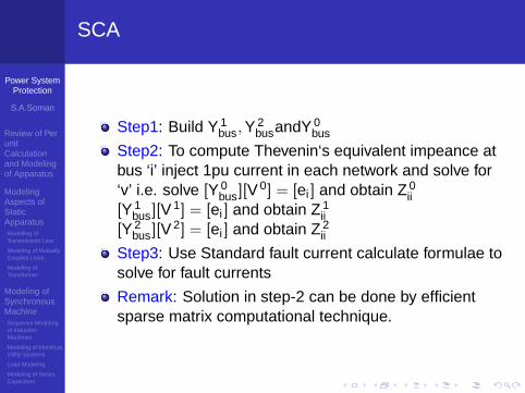
Step1: Build Y 1bus, Y 2
busandY 0bus
Step2: To compute Thevenin‘s equivalent impeance atbus ‘i’ inject 1pu current in each network and solve for‘v’ i.e. solve [Y 0
bus][V0] = [ei ] and obtain Z 0
ii[Y 1
bus][V1] = [ei ] and obtain Z 1
ii[Y 2
bus][V2] = [ei ] and obtain Z 2
ii
Step3: Use Standard fault current calculate formulae tosolve for fault currents
Remark: Solution in step-2 can be done by efficientsparse matrix computational technique.
Power SystemProtection
S.A.Soman
Review of PerunitCalculationand Modelingof Apparatus
ModelingAspects ofStaticApparatusModelling ofTransmission Line
Modeling of MutuallyCoupled Lines
Modeling ofTransformer
Modeling ofSynchronousMachineSequence Modelingof InductionMachines
Modeling of ElectricalUtility Systems
Load Modeling
Modeling of SeriesCapacitors
SequenceNetworkAdmittanceMatrixFormulation
Short CircuitAnalysisUsingSequenceComponentsCalculation of ShortCircuit MVA
Sequence Modeling of Power Apparatus
1 Review of Per unit Calculation and Modeling ofApparatus
2 Modeling Aspects of Static ApparatusModelling of Transmission LineModeling of Mutually Coupled LinesModeling of Transformer
3 Modeling of Synchronous MachineSequence Modeling of Induction MachinesModeling of Electrical Utility Systems
Load ModelingModeling of Series Capacitors
4 Sequence Network Admittance Matrix Formulation
5 Short Circuit Analysis Using Sequence ComponentsCalculation of Short Circuit MVA

Power SystemProtection
S.A.Soman
Review of PerunitCalculationand Modelingof Apparatus
ModelingAspects ofStaticApparatusModelling ofTransmission Line
Modeling of MutuallyCoupled Lines
Modeling ofTransformer
Modeling ofSynchronousMachineSequence Modelingof InductionMachines
Modeling of ElectricalUtility Systems
Load Modeling
Modeling of SeriesCapacitors
SequenceNetworkAdmittanceMatrixFormulation
Short CircuitAnalysisUsingSequenceComponentsCalculation of ShortCircuit MVA
Calculation of Short Circuit MVA
3φ− short circuit MVA = I3φ(in pu)× 3φ− base MVA
S − L − G Short circuit MVA = IS−L−G(in pu)× 3φ−base MVA

Power SystemProtection
S.A.Soman
Review of PerunitCalculationand Modelingof Apparatus
ModelingAspects ofStaticApparatusModelling ofTransmission Line
Modeling of MutuallyCoupled Lines
Modeling ofTransformer
Modeling ofSynchronousMachineSequence Modelingof InductionMachines
Modeling of ElectricalUtility Systems
Load Modeling
Modeling of SeriesCapacitors
SequenceNetworkAdmittanceMatrixFormulation
Short CircuitAnalysisUsingSequenceComponentsCalculation of ShortCircuit MVA
Closing Remarks
Fault analysis methods are quasi steady state model ofdynamic system. It uses Limited Data
More accurate models requires EMTP -EMTP requireslarge data
approximate asymmetrical currents due to dc offset infauls analysis are obtained by using approximatemultiplier (... .....)
SCA ysed for relay coordination, breaker () selectionetc.....