Embed Size (px)
Citation preview

PPLIED
AApplied Energy 82 (2005) 181–195
www.elsevier.com/locate/apenergy
ENERGY
Power optimization of an endoreversible closedintercooled regenerated Brayton-cycle coupled to
variable-temperature heat-reservoirs
Wenhua Wang a, Lingen Chen a,*, Fengrui Sun a, Chih Wu b
a Postgraduate School, Naval University of Engineering, Wuhan 430033, PR Chinab Mechanical Engineering Department, US Naval Academy, Annapolis, MD 21402, USA
Accepted 20 August 2004
Available online 21 December 2004
Abstract
In this paper, in the viewpoint of finite-time thermodynamics and entropy-generation min-
imization are employed. The analytical formulae relating the power and pressure-ratio are
derived assuming heat-resistance losses in the four heat-exchangers (hot- and cold-side heat
exchangers, the intercooler and the regenerator), and the effect of the finite thermal-capacity
rate of the heat reservoirs. The power optimization is performed by searching the optimum
heat-conductance distributions among the four heat-exchangers for a fixed total heat-exchan-
ger inventory, and by searching for the optimum intercooling pressure-ratio. When the optimi-
zation is performed with respect to the total pressure-ratio of the cycle, the maximum power is
maximized twice and a �double-maximum� power is obtained. When the optimization is per-
formed with respect to the thermal capacitance rate ratio between the working fluid and the
heat reservoir, the double-maximum power is maximized again and a thrice-maximum power
is obtained. The effects of the heat reservoir�s inlet-temperature ratio and the total heat-exchan-
ger inventory on the optimal performance of the cycle are analyzed by numerical examples.
� 2004 Elsevier Ltd. All rights reserved.
Keywords: Finite-time thermodynamics; Brayton cycle; Intercooled; Regenerated; Power optimization
0306-2619/$ - see front matter � 2004 Elsevier Ltd. All rights reserved.
doi:10.1016/j.apenergy.2004.08.007
* Corresponding author. Tel.: +86 27 83615046; fax: +86 27 83638709.
E-mail addresses: [email protected], [email protected] (L. Chen).

Nomenclature
C thermal-capacity rate (kW/K)
E effectivenesses of heat exchangers
k principal specific-heats ratio
N number of heat-transfer units
P power (kW)
p pressure (MPa)Q the rate at which heat is transferred (kJ)
T temperature (K)
U heat conductance (kW/K)
u heat-conductance distributiion
g efficiency
p total pressure-ratio
p1 intercooling pressure-ratio
s1 cycle heat-reservoir temperature-ratios2 cooling fluid in the intercooler and the cold-side heat-reservoir of tem-
peratures ratio
Subscripts
H, h hot-side heat-exchanger
I, i intercooler
in inlet
L, I cold-side heat-exchangermax maximum
max, 2 double maximum
opt optimum
out outlet�Pmax maximum dimensionless power of the cycle�Pmax;2 double maximum dimensionless power of the cycle
R, r regenerator
T totalwf working fluid
l, 2, 3, 4, 5, 6, 7, 8 state points
182 W. Wang et al. / Applied Energy 82 (2005) 181–195
1. Introduction
Since the finite-time thermodynamics (FTT, or endoreversible thermodynamics,
or entropy-generation minimization (EGM), or thermodynamic optimization) was
introduced [1–3], much work has been undertaken on the performance analysis
and optimization of finite-time processes and finite-size devices [4–11]. The FTT per-
formance of closed [12–25,2,27–29] or open [30,31], simple [12–15,22–25,27,28,30],

W. Wang et al. / Applied Energy 82 (2005) 181–195 183
regenerated [16–21,29,31], and intercooled [26], endoreversible [12,13,24,26,27] or
irreversible [14–23,25,28–31] Brayton-cycles has been analyzed and optimized for
the power, specific power, power density, efficiency, and ecological optimization
objectives with heat-transfer irreversibility and/or internal irreversibilities [12–31].
On the basis of that research Chen et al. [32,33] and Wang et al. [34] analyzed theperformance of endoreversible [32] and irreversible [33,34] intercooled and regener-
ated Brayton-cycles coupled constant-temperature [33] and variable-temperature
[32,34] heat-reservoirs, and derived the power and efficiency expressions for the cy-
cles. The further step of this paper beyond that in [32–34] is to optimize the power of
an endoreversible closed intercooled regenerated Brayton-cycle coupled to variable-
temperature heat-reservoirs using FTT by searching the optimum heat-conductance
distributions among the four heat-exchangers (the hot- and cold-side heat-exchang-
ers, the intercooler and the regenerator) for a fixed total heat-exchanger inventory,searching for the optimal intercooling pressure-ratio and the optimal total pres-
sure-ratio, and searching for the optimal matching of the thermal capacitance rate
ratio between the working, fluid and the heat reservoir. The effects of the heat-reser-
voir inlet-temperature ratio and the total heat-exchanger inventory on the optimal
performance of the cycle are analyzed by detailed numerical examples.
2. Theoretical model
An endoreversible closed intercooled regenerated Brayton-cycle 1–2–3–4–5–6–1
coupled to variable-temperature heat reservoirs is shown in Fig. 1. The high-temper-
ature (hot-side) heat-reservoir is considered to have a thermal capacity rate CH and
the inlet and the outlet temperatures of the heating fluid are THin and THout, respec-
tively. The low-temperature (cold-side) heat-reservoir is considered to have a thermal
capacity rate CL and the inlet and the outlet temperatures of the cooling fluid are
TLin and TLout, respectively. The cooling fluid in the intercooler is considered to havea thermal-capacity rate CI and the inlet and the outlet temperatures are TLin and
TIout, respectively. Processes 1 ! 2 and 3 ! 4 are isentropic adiabatic compression
in the low- and high-pressure compressors, while the process 5! 6 is isentropic
expansion in the turbine. Process 2 ! 3 is an isobaric intercooling in the intercooler.
Process 4 ! 7 is an isobaric absorbed-heat process and process 6 ! 8 an isobaric
evolved heat-process in the regenerator. Process 7 ! 5 is an isobaric absorbed-heat
process in the hot-side heat exchanger and process 8 ! 1 an isobaric evolved heat-
process in the cold-side heat-exchanger.Assuming that the working fluid used in the cycle is an ideal gas with a constant
thermal-capacity rate (mass-flow rate and specific heat product) Cwf, the heat
exchangers between the working fluid and the heat reservoirs, the regenerator and
the intercooler are counter-flow and the heat conductances (heat-transfer surface
area and heat-transfer coefficient product) of the hot- and cold-side heat exchangers,
the regenerator and the intercooler are UH, UL, UR and UI respectively. According to
the properties of the working fluid, the heat-transfer processes, the properties of the
heat reservoirs and the theory of heat-exchangers, the rate (QH) at which heat is

Fig. 1. T–S diagram of an endoreversible intercooled regenerated Brayton-cycle coupled to variable-
temperature reservoirs.
184 W. Wang et al. / Applied Energy 82 (2005) 181–195
transferred from the heat source to the working fluid, the rate (QL) at which heat is
rejected from the working fluid to the heat sink, the rate (QR) of heat regenerated inthe regenerator, and the rate (QI) of heat exchanged in the intercooler are, respec-
tively, given by
QH ¼ CwfðT 5 � T 7Þ ¼ UH
ðTHin � T 5Þ � ðTHout � T 7Þln½ðTHin � T 5Þ=ðTHout � T 7Þ�
¼ CHðTHin � THoutÞ ¼ CHminEHðTHin � T 7Þ; ð1Þ
QL ¼ CwfðT 8 � T 1Þ ¼ UL
ðT 8 � T LoutÞ � ðT 1 � T LinÞln½ðT 8 � T LoutÞ=ðT 1 � T LinÞ�
¼ CLðT Lout � T LinÞ
¼ CLminELðT 8 � T LinÞ; ð2Þ
QR ¼ CwfðT 7 � T 4Þ ¼ CwfðT 6 � T 8Þ ¼ CwfERðT 6 � T 4Þ ð3Þand
QI ¼ CwfðT 2 � T 3Þ ¼ U I
ðT 2 � T IoutÞ � ðT 3 � T IinÞln½ðT 2 � T IoutÞ=ðT 3 � T IinÞ�
¼ CIðT Iout � T IinÞ
¼ CIminEIðT 2 � T IinÞ; ð4Þ
where EH, EL, ER and EI are the component (the hot-and cold-side heat-exchangers,
the regenerator and the intercooler) effectivenesses, and are defined as
EH ¼ 1� exp½�NHð1� CHmin=CHmaxÞ�1� ðCHmin=CHmaxÞ exp½�NHð1� CHmin=CHmaxÞ�
; ð5Þ

W. Wang et al. / Applied Energy 82 (2005) 181–195 185
EL ¼ 1� exp½�NLð1� CLmin=CLmaxÞ�1� ðCLmin=CLmaxÞ exp½�NLð1� CLmin=CLmaxÞ�
; ð6Þ
ER ¼ NR=ðNR þ 1Þ ð7Þ
and
EI ¼1� exp½�N Ið1� CImin=CImaxÞ�
1� ðCImin=CImaxÞ exp½�N Ið1� CImin=CImaxÞ�; ð8Þ
where CHmin and CHmax are the smaller and the larger of the two capacitance rates
CH and Cw/f, respectively; CLmin and CLmax are the smaller and the larger of the twocapacitance rates CL and Cwf, respectively; CImin and CImax are the smaller and the
larger of the two capacitance rates CI, and Cwf, respectively. The number of heat
transfer units NH, NL, NR and NI of the hot- and cold-side heat-exchangers, the
regenarator and the intercooler, respectively, are
NH ¼ UH=CHmin; NL ¼ UL=CLmin; NR ¼ UR=Cwf ; N I ¼ U I=CImin; ð9Þwhere
CHmin ¼ minfCH;Cwfg; CHmax ¼ maxfCH;Cwfg; ð10Þ
CLmin ¼ minfCL;Cwfg; CLmax ¼ maxfCL;Cwfg; ð11Þand
CImin ¼ minfCI;Cwfg; CImax ¼ maxfCI;Cwfg: ð12ÞThe cycle�s power-output and the cycle efficiency are defined as
P ¼ QH � QL � QI; ð13Þ
g ¼ 1� ðQL þ QIÞ=QH: ð14Þ
Defining the working-fluid�s isentropic temperature-ratios x and y for the low-
pressure compressor and total compression-process gives
x ¼ T 2=T 1 ¼ ðP 2=P 1Þm ¼ pm1 ; ð15Þ
y ¼ T 5=T 6 ¼ ðP 5=P 6Þm ¼ pm; ð16Þ
where m = (k � 1)/k (k is the ratio of principal specific heats), p1 is the intercooling
pressure ratio and p is the total pressure-ratio. The temperature ratio in the high-
pressure compressor can be written as
y=x ¼ P 4=P 3 ¼ T 4=T 3: ð17Þ
Combining Eqs. (1)–(17), one can find the power output and the efficiency of the
endoreversible intercooled regenerated Brayton-cycle coupled to the variable-
temperature heat reservoirs. The dimensionless power �P ð�P ¼ P=ðCLT LinÞÞ and the
efficiency g are

186 W. Wang et al. / Applied Energy 82 (2005) 181–195
ð18Þ
ð19Þ
Fig. 2. Optimal dimensionless power versus total heat-exchanger inventory and intercooling pressure-
ratio.
Fig. 3. Maximum dimensionless power versus heat-reservoir inlet temperature-ratio and total pressure-
ratio.

W. Wang et al. / Applied Energy 82 (2005) 181–195 187
where s = THin/TLin is the cycle�s heat-reservoir inlet temperature ratio, s2 = TLin/
TLin is the inlet temperature ratio of the cooling fluid in the intercooler and the
cold-side heat-reservoir, a1 = CHmin/Cwf, a2 = CLmin/Cwf and a3 = CImin/Cwf.
3. Power optimization
Eq. (18) indicates that the cycle�s dimensionless-power �P is a function of the total
pressure-ratio p, intercooling pressure-ratio p1, heat conductance UH of the hot-side
heat-exchanger, heat conductance UL of the cold-side heat-exchanger, heat conduc-
tance UR of the regenerator, heat conductance UI of the intercooler, and the thermal
capacitance rate Cwf of the working fluid for the fixed boundary conditions of the
Fig. 4. Efficiency at maximum dimensionless power versus heat-reservoir inlet-temperature ratio and total
pressure-ratio.
Fig. 5. Maximum dimensionless power versus corresponding efficiency and heat reservoir inlet-
temperature ratio.
188 W. Wang et al. / Applied Energy 82 (2005) 181–195
cycle. For the fixed p, p1 and Cwf,there exist a group of optimal distributions among
UH, UL, UR and UI, which lead to the optimal dimensionless-power �P opt, as the total
heat-exchanger inventory (UT = UH + UL + UR + Ul) is fixed. For the fixed p and
Cwf, there exist an optimal intercooling pressure-ratio and a group of optimal distri-
butions among UH, UL, UR and UI, as UT is fixed, that lead to the maximum dimen-sionless-power Pmax. Optimizing the maximum power with respect to the total
pressure-ratio p for the fixed Cwf, one can obtain the �double-maximum� power�Pmax;2. When the optimization is performed with respect to the thermal-capacitance
rate ratio between the working fluid and the heat reservoir, the �double-maximum�power is maximized again and a �thrice-maximum� power is obtained.
For the fixed total heat-exchange inventory (UT = UH + UL + UR + UI), defining
uh ¼ UH=UT; ul ¼ UL=UT; ui ¼ U I=UT and ur ¼ 1� uh � u1 � ui;
ð20Þ
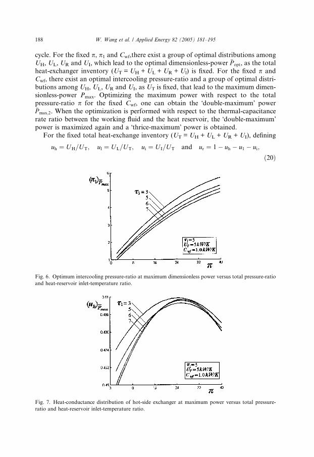
Fig. 6. Optimum intercooling pressure-ratio at maximum dimensionless power versus total pressure-ratio
and heat-reservoir inlet-temperature ratio.
Fig. 7. Heat-conductance distribution of hot-side exchanger at maximum power versus total pressure-
ratio and heat-reservoir inlet-temperature ratio.

W. Wang et al. / Applied Energy 82 (2005) 181–195 189
leads to
UH ¼ uhUT; UL ¼ u1UT; U I ¼ uiUT and UR ¼ ð1� uh � ul � uiÞUT:
ð21ÞAdditionally, one has the constraints
0 < uh þ ul < 1; 0 < uh þ ui < 1; 0 < ul þ ui < 1 and
0 < uh þ ul þ ui < 1:ð22Þ
The power optimization is performed by numerical calculations, and the compu-tational program is integrated with the optimization toolbox of MATLAB. In the
calculations, k = 1.4, TLin = 300 K, s2 = 1, and CH = CL = CI = 1.2 kW/K are set.
Fig. 8. Heat conductance distribution of cold-side exchanger at maximum power versus total pressure-
ratio and heat-reservoir inlet-temperature ratio.
Fig. 9. Heat-conductance distribution of intercooler at maximum power versus total pressure-ratio and
heat-reservoir inlet-temperature ratio.

190 W. Wang et al. / Applied Energy 82 (2005) 181–195
Fig. 2 shows the characteristic of the optimal dimensionless-power �P opt versus to-
tal heat-exchanger inventory UT and intercooling pressure-ratio p1. The optimal
dimensionless-power �P opt has a maximum value, i.e. the maximum dimensionless-
power �Pmax, with respect to p1. For a fixed p1, one can find that the increment of�P opt is less as the total heat-conductance UT increases.
Figs. 3–9 show the characteristics of the maximum dimensionless power �Pmax and
its corresponding parameters, i.e., efficiency g�Pmax, optimal intercooling pressure-ratio
ðp1Þ�Pmax, optimal heat-conductance distribution ðuhÞ�Pmax
of the hot-side heat-exchan-
ger, optimal heat-conductance distribution ðulÞ�Pmaxof the cold-side heat-exchanger
and optimal heat-conductance distribution ðuiÞ�Pmaxof the intercooler, versus the total
pressure-ratio p and heat reservoir-inlet temperature-ratio s1.
Fig. 10. �Double-maximum� dimensionless power and its corresponding efficiency versus heat-reservoir
inlet-temperature ratio.
Fig. 11. Total pressure-ratio at �double-maximum� dimensionless power versus heat-reservoir inlet-
temperature ratio.

W. Wang et al. / Applied Energy 82 (2005) 181–195 191
Fig. 2 shows that the characteristic curve of �Pmax versus p is parabolic like. As pincreases, �Pmax will increase to its peak value, i.e. a �double-maximum� dimensionless
power �Pmax;2, and then decrease smoothly: �Pmax increases as the heat reservoir inlet
temperature ratio s1 increases. Fig. 5 shows that the characteristic curve of �Pmax ver-
sus its corresponding efficiency g�Pmaxis part loop-shaped that is similar to that of a
generalized irreversible Carnot heat-engine [35], and it indicates the optimal work-
ing-range of the cycle. Fig. 6 shows that ðp1Þ�Pmaxis an increasing function of p, while
a decreasing function of s1. Fig. 7 shows that the characteristic curve of ðuhÞ�Pmaxver-
sus p is parabolic like. Fig. 8 shows that when s1 is larger than a specified value (e.g.,
s1 P 5), ðulÞ�Pmaxwill increase first, and then decrease as p increases; if s1, is smaller
than some specified value (e.g., s1 6 3), ðulÞ�Pmaxwill decrease monotonically;
Fig. 12. �Double-maximum� dimensionless power and its corresponding efficiency versus total heat-
exchanges inventory.
Fig. 13. Total pressure ratio at �double-maximum� dimensionless power versus total heat-exchanger
inventory.

192 W. Wang et al. / Applied Energy 82 (2005) 181–195
ðulÞ�Pmaxincreases with increases in s1. Fig. 9 shows that ðulÞ�Pmax
is an increasing func-
tion of p, but a decreasing function of s1.Figs. 10 and 11 illustrate the characteristics of the �double-maximum� dimension-
less power �Pmax;2 and its corresponding efficiency g�Pmax;2and optimal total pressure-
ratio p�Pmax;2versus the heat reservoir inlet-temperature ratio s1. Figs. 12 and 13
illustrate the characteristics of �Pmax;2; g�Pmax;2and p�Pmax;2
versus the total heat-
conductance UT. It can be seen that �Pmax;2; g�Pmax;2and p�Pmax;2
are increasing functions
of s1. As UT increases, �Pmax;2 and p�Pmax;2increase, but the increment will be less and
less. The characteristic curve of g�Pmax;2versus UT is parabolic like and it exhibits an
optimal working range of the cycle, the power output is larger and the corresponding
efficiency is higher.
Fig. 14. �Double-maximum� dimensionless-power and its corresponding efficiency versus thermal-
capacitance ratio between working fluid and heat reservoir.
Fig. 15. Optimum total pressure-ratio at �double-maximum� dimensionless power versus thermal-
capacitance rate ratio between working fluid and heat reservoir.

W. Wang et al. / Applied Energy 82 (2005) 181–195 193
Figs. 14 and 15 illustrate the characteristics of the �double-maximum� dimension-
less-power �Pmax;2 and its corresponding efficiency g�Pmax;2and optimal total pressure-
ratio p�Pmax;2versus the thermal-capacitance rate ratio Cwf/CL between the working
fluid and cold-side heat-reservoir. It can be seen that �Pmax;2 has an additional max-
imum with respect to Cwf/CL. For the conditions given above, the optimal ther-mal-capacitance rate ratio between the working fluid and cold-side heat-reservoir
is about 0.8 for the �thrice-maximum� power. Similar characteristic can be found be-
tween g�Pmax;2and Cwf/CL. As Cwf/CL increases, p�Pmax;2
decreases first, and then in-
creases sharply.
4. Conclusion
Finite-time thermodynamics has been applied to optimize the power of an endo-
reversible closed intercooled regenerated Brayton-cycle coupled to variable-temper-
ature heat-reservoirs. The analysis indicates that there exists a group of optimal
values for p1, UH, UL, UR and UI which lead to the maximum dimensionless-power.
Furthermore, there exists an optimal total pressure-ratio that leads to a �double-max-
imum� power-output. The power ð�P opt; �Pmax or �Pmax;2Þ increases with the increases in
the cycle�s heat-reservoir temperature-ratio and the total heat-exchanger inventory.
When UT is larger than a particular value, the increment of the cycle power becomesless and less. The �double maximum� power has an additional maximum with respect
to the thermal-capacitance rate ratio between the working fluid and heat reservoir.
An optimal cycle working-range, i.e. high power output and high efficiency, can
be obtained according to the characteristics of the maximum power and/or the dou-
ble maximum power and its corresponding efficiency. The analysis and optimization
presented herein may provide some guidelines for power-optimization design for the
closed gas-turbine power-plants.
Acknowledgements
This paper is supported by the Foundation for the Authors of Nationally Excel-
lent Doctoral Dissertations of PR China (Project No. 200136) and the Natural Sci-
ence Foundation of the Naval University of Engineering of PR China (Project No.
HGDJJ03016).
References
[1] Novikov II. The efficiency of atomic-power stations. Atommaya Energiya 1957;3(11):409.
[2] Chambadal P. Les centrales nuclearies. Paris: Armand Colin; 1957. p. 41–58.
[3] Curzon FL, Ahlborn B. Efficiency of a Carnot engine at maximum power-output. Am J Phys
1975;43(1):22–4.
[4] Andresen B. Finite-time thermodynamics. Physics Laboratory II, University of Copenhagen; 1983.
[5] De Vos A. Endoreversible thermodynamics of solar-energy conversion. Oxford: Oxford University
Press; 1992.

194 W. Wang et al. / Applied Energy 82 (2005) 181–195
[6] Bejan A. Entropy-generation minimization: the new thermodynamics of finite-size devices and finite-
time processes. J Appl Phys 1996;79(3):1191–218.
[7] Chen L, Wu C, Sun F. Finite-time thermodynamic optimization or entropy-generation minimization
of energy systems. J Non-Equilib Thermodyn 1999;24(4):327–59.
[8] Berry RS, Kazakov VA, Sieniutycz S, Szwast Z, Tsirlin AM. Thermodynamic optimization of finite-
time processes. Chichester: Wiley; 1999.
[9] Sieniutycz S, De Vos A, editors. Thermodynamics of energy conversion and transport. New
York: Springer; 2000.
[10] Wu C, Chen L, Chen J, editors. Recent advances in finite-time thermodynamics. New York: Nova
Science Publishers; 1999.
[11] Chen L, Sun F, editors. Advances in finite-time thermodynamics: analysis and optimization. New
York: Nova Science Publishers; 2004.
[12] Wu C. Power optimization of an endoreversible Brayton gas-turbine heat-engine. Energy Conver
Mgmt 1991;31(6):561–5.
[13] Ibrahim OM, Klein SA, Mitchell JW. Optimum heat power-cycles for specified boundary-conditions.
Trans ASME J Eng Gas Turbine Pow 1991;113(4):514–21.
[14] Chen L, Sun F, Wu C. Performance analysis of an irreversible Brayton heat-engine. J Inst Energy
1997;70(482):2–8.
[15] Feidt M. Optimization of Brayton-cycle engine in contact with fluid thermal capacities. Rev Gen
Therm 1996;35(418/419):662–6.
[16] Wu C, Chen L, Sun F. Performance of a regenerative Brayton heat-engine. Energy, Int J
1996;21(2):71–6.
[17] Chen L, Sun F, Wu C, Kiang RL. Theoretical analysis of the performance of a regenerated closed
Brayton-cycle with internal irreversibilities. Energy Conver Mgmt 1997;18(9):871–7.
[18] Chen L, Ni N, Cheng G, Sun F. FTT performance of a closed regenerated Brayton-cycle coupled to
variable-temperature heat-reservoirs. Proceedings of the international conference on marine
engineering. (Shanghai, China); 1996 (Nov 4–8) p. 3.7.1–7.
[19] Chen L, Ni N, Cheng G, Sun F, Wu C. Performance analysis for a real closed regenerated Brayton-
cycle via methods of finite-time thermodynamics. Int J Ambient Energy 1999;20(2):95–104.
[20] Chen L, Sun F, Wu C. Effect of heat resistance on the performance of closed gas-turbine regenerative
cycles. Int J Pow Energy Sys 1999;19(2):141–5.
[21] Roco JMM, Veleasco S, Medina A, Calvo Hernaudez A. Optimum performance of a regenerative
Brayton thermal-cycle. J Appl Phys 1997;82(6):2735–41.
[22] Cheng CY, Chen CK. Power optimization of an irreversible Brayton heat-engine. Energy Sour
1997;19(5):461–74.
[23] Cheng CY, Chen CK. Efficiency optimizations of an irreversible Brayton heat-engine. Trans ASME J
Energy Res Tech 1998;120(2):143–8.
[24] Cheng CY, Chen CK. Ecological optimization of an endoreversible Brayton-cycle. Energy Conver
Mgmt 1998;39(1/2):33–44.
[25] Cheng CY, Chen CK. Ecological optimization of an irreversible Brayton heat-engine. J Phys D: Appl
Phys 1999;32(3):350–7.
[26] Cheng CY, Chen CK. Maximum power of an endoreversible intercooled Brayton-cycle. Int J Energy
Res 2000;24(6):485–94.
[27] Chen L, Zheng J, Sun F, Wu C. Optimum distribution of heat-exchanger inventory for power-density
optimization of an endoreversible closed Brayton-cycle. J Phys D: Appl Phys 2001;34(3):422–7.
[28] Chen L, Zheng J, Sun F, Wu C. Power density optimization for an irreversible closed Brayton-cycle.
Open Sys Inform Dyn 2001;8(3):241–60.
[29] Chen L, Zheng J, Sun F, Wu C. Power-density analysis and optimization of a regenerated closed
variable-temperature heat-reservoir Brayton-cycle. J Phys D: Appl Phys 2001;34(11):1727–39.
[30] Radcenco V, Vergas JVC, Bejan A. Thermodynamic optimization of a gas-turbine power plant with
pressure drop irreversibilities. Trans ASME J Energy Res Tech 1998;120(3):233–40.
[31] Chen L, Li Y, Sun F, Wu C. Power optimization of open-cycle regenerator gas-turbine power-plants.
Appl Energy 2004;78(2):199–218.

W. Wang et al. / Applied Energy 82 (2005) 181–195 195
[32] Chen L, Wang W, Sun F, Wu C. Performance of a variable-temperature heat-reservoir endoreversible
closed intercooled regenerated Brayton-cycle. In: Chen L, Sun F, editors. Advances in finite-time
thermodynamics: analysis and optimization. New York: Nova Science Publishers; 2004. p. 161–78.
[33] Chen L, Wang W, Sun F, Wu C. Closed intercooled regenerated Brayton-cycle with constant-
temperature heat reservoirs. Appl Energy 2004;77(4):429–46.
[34] Wang W, Chen L, Sun F, Wu C. Performance analysis for an irreversible closed variable-temperature
heat-reservoir intercooled regenerated Brayton-cycle. Energy Conver Mgmt 2003;44(17):2713–32.
[35] Chen L, Sun F, Wu C. Effect of heat-transfer law on the performance of a generalized irreversible
Carnot engine. J Phys D: Appl Phys 1999;32(2):99–105.