Embed Size (px)
Citation preview

XMCTM in application - Power Management Bus (PMBus™) XMCTM microcontrollers August 2016

Agenda (1/2)
Overview
Key features
Specification
System block diagram
Hardware overview
Software overview
Highlight MCU features
Get started
1
2
3
4
5
6
7
8
2 Copyright © Infineon Technologies AG 2016. All rights reserved.
Agenda (2/2)
Resource listing 9
3 Copyright © Infineon Technologies AG 2016. All rights reserved.

Agenda
Overview
Key features
Specification
System block diagram
Hardware overview
Software overview
Highlight MCU features
Get started
1
2
3
4
5
6
7
8
4 Copyright © Infineon Technologies AG 2016. All rights reserved.

Power Management Bus (PMBus™) – Overview
› The Power Management Bus (PMBus™) is a standard for communication and power management in terms of :
– Inventory
– e.g.: Device ID
– Configuration
– e.g.: On/Off configuration, fault/warnings
– Control
– e.g.: Sequencing delay/rampfault response
– Telemetry
– e.g.: Vout, Iout, power, temperature, peak values
– Status
– e.g.: Comms, date, temp
5 Copyright © Infineon Technologies AG 2016. All rights reserved.

Agenda
Overview
Key features
Specification
System block diagram
Hardware overview
Software overview
Highlight MCU features
Get started
1
2
3
4
5
6
7
8
6 Copyright © Infineon Technologies AG 2016. All rights reserved.

Power Management Bus (PMBus™) – Key features
› Free and open standard
› Based on I2C:
– Bi-directional communication between master and slave
› Low cost
› Robust protocol:
– Timeouts forcing bus reset
– SMBALERT# line for interrupts
– Packet error checking (PEC)
– Host notify
– CONTROL signal for on/off control
7 Copyright © Infineon Technologies AG 2016. All rights reserved.

Agenda
Overview
Key Features
Specification
System Block Diagram
Hardware Overview
Software Overview
Highlight MCU Features
Get Started
1
2
3
4
5
6
7
8
8 Copyright © Infineon Technologies AG 2016. All rights reserved.
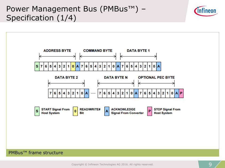
Power Management Bus (PMBus™) – Specification (1/4)
PMBus™ frame structure
9 Copyright © Infineon Technologies AG 2016. All rights reserved.

Power Management Bus (PMBus™) – Specification (2/4)
› Nominal bus voltage: 2.7 VDC to 5.5 VDC
› Baudrate : 100 Kbit/s or 400 Kbit/s
› Several format frame (protocols) supporting many functional commands
10 Copyright © Infineon Technologies AG 2016. All rights reserved.
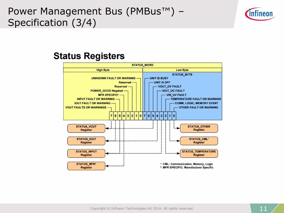
Power Management Bus (PMBus™) – Specification (3/4)
11 Copyright © Infineon Technologies AG 2016. All rights reserved.
Power Management Bus (PMBus™) – Specification (4/4)
› Parametric information
– Input voltage
– Input current
– Output voltage
– Output current
– Temperature (up to 3 sensors)
– Fan speed (up to 2 fans)
– Duty cycle
– Switching frequency
12 Copyright © Infineon Technologies AG 2016. All rights reserved.

Agenda
Overview
Key features
Specification
System block diagram
Hardware overview
Software overview
Highlight MCU features
Get started
1
2
3
4
5
6
7
8
13 Copyright © Infineon Technologies AG 2016. All rights reserved.

Power Management Bus (PMBus™) – System block diagram (1/2)
System block diagram: PMBus™
14 Copyright © Infineon Technologies AG 2016. All rights reserved.

Power Management Bus (PMBus™) – System block diagram (2/2)
Application example – server system
› Power supplies for server application
› Load sharing capability with OR-ing
› Use PMBus™ to turn-on and turn-off one power supply for efficiency purpose
Power Supply
Power Supply
Management Controller
Hot Swap ModuleOring
PMBus
Rectifier DC-DC Point Of
Load
Point Of Load
Point Of Load
AC
Input
Server System
Power Supply
Power Supply
Management Controller
Hot Swap ModuleOring
PMBus
Rectifier DC-DC Point Of
Load
Point Of Load
Point Of Load
AC
Input
Server System
Power Supply
Power Supply
Management Controller
Hot Swap ModuleOring
PMBus
Rectifier DC-DC Point Of Load
Point Of Load
Point Of Load
AC
Input
PM
Bu
s
Server System
15 Copyright © Infineon Technologies AG 2016. All rights reserved.

Agenda
Overview
Key features
Specification
System block diagram
Hardware overview
Software overview
Highlight MCU features
Get started
1
2
3
4
5
6
7
8
16 Copyright © Infineon Technologies AG 2016. All rights reserved.

Power Management Bus (PMBus™) – Hardware overview (1/2)
› Several peripherals can are used for supporting the characteristic of the PMBus™:
– USIC module for the I2C layer
– NVIC for handling the interrupts
– ERU for checkings
– SYSTICK for the timeouts
– GPIO for SMBALERT# and control signals
17 Copyright © Infineon Technologies AG 2016. All rights reserved.

Power Management Bus (PMBus™) – Hardware overview (2/2)
› USIC module
– Each USIC module provides two universal serial communication channels to interface with external devices. It is tailored for various serial protocols like I2C. A shared 64 words FIFO buffer is available in each USIC module
SRx
UART
SPI/Dual SPI/Quad SPI
LIN
IIC
IIS
UART
SPI/Dual SPI/Quad SPI
LIN
IIC
IIS
IO Stage
IO Stage
Baud rate Generator
Baud rate Generator
Optional
Shared 64
Word FIFO
Buffer
Date
Handling and
More
Data Shifting
Optional
Shared 64
Word FIFO
Buffer
Date
Handling and
More
Interruption Generation
USIC channel 0
USIC channel 1
𝑓𝑝𝑏
Com
mon B
us I
nte
rface
Pin
s
𝑓𝑝𝑏
Data Shifting
18 Copyright © Infineon Technologies AG 2016. All rights reserved.
Agenda
Overview
Key features
Specification
System block diagram
Hardware overview
Software overview
Highlight MCU features
Get started
1
2
3
4
5
6
7
8
19 Copyright © Infineon Technologies AG 2016. All rights reserved.
Power Management Bus (PMBus™) – Software overview (1/3)
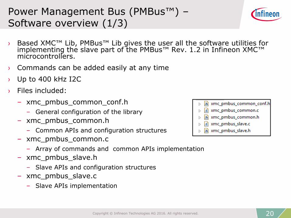
› Based XMC™ Lib, PMBus™ Lib gives the user all the software utilities for implementing the slave part of the PMBus™ Rev. 1.2 in Infineon XMC™ microcontrollers.
› Commands can be added easily at any time
› Up to 400 kHz I2C
› Files included:
– xmc_pmbus_common_conf.h
– General configuration of the library
– xmc_pmbus_common.h
– Common APIs and configuration structures
– xmc_pmbus_common.c
– Array of commands and common APIs implementation
– xmc_pmbus_slave.h
– Slave APIs and configuration structures
– xmc_pmbus_slave.c
– Slave APIs implementation
20 Copyright © Infineon Technologies AG 2016. All rights reserved.

Power Management Bus (PMBus™) – Software overview (2/3)
Flow chart: Power Management Bus (PMBus™) – software overview
PMBus™ layer
USIC (I2C) Other
peripherals (ERU, GPIO, NVIC, SYSTICK)
Interrupts handlers
Command array
XMC_PMBUS_SLAVE_Task
& PMBus™ Lib APIs
Application code & commands
callbacks
XMC™ Lib
PMBus™ slave software abstraction layer
DAVE™ Apps
21 Copyright © Infineon Technologies AG 2016. All rights reserved.

Power Management Bus (PMBus™) – Software overview (3/3)
Flow chart: Power Management Bus (PMBus™) – software overview
Read data in local buffer
Receive interrupt
Execute command
callback from array
Protocol related interrupt
YES NO Slave_ready = = true?
Slave task:
Does the needed checkings and executes the respective command callback
› Identify PMBus™ protocol
› After Stop condition : Slave_ready = true
› Check: - PEC - Data & attributes
› Command number
= array position
22 Copyright © Infineon Technologies AG 2016. All rights reserved.
Agenda
Overview
Key features
Specification
System block diagram
Hardware overview
Software overview
Highlight MCU features
Get started
1
2
3
4
5
6
7
8
23 Copyright © Infineon Technologies AG 2016. All rights reserved.

Power Management Bus (PMBus™) – Highlight MCU features – PMBus™ Lib
› Library available supporting main characteristic of the protocol:
– SMBALERT#
– Host notify
– Control signal
– PEC
– Timeout
– Supports all types of PMBus™ data format:
– Linear
– DIRECT
– VID (only for Vout commands)
24 Copyright © Infineon Technologies AG 2016. All rights reserved.

Power Management Bus (PMBus™) – Highlight MCU features - USIC module (1/4)
› USIC module
– Each USIC module provides two universal serial communication channels to interface with external devices. It is tailored for various serial protocols like I2C. A shared 64 words FIFO buffer is available in each USIC module
SRx
UART
SPI/Dual SPI/Quad SPI
LIN
IIC
IIS
UART
SPI/Dual SPI/Quad SPI
LIN
IIC
IIS
IO Stage
IO Stage
Baud rate Generator
Baud rate Generator
Optional
Shared 64
Word FIFO
Buffer
Date
Handling and
More
Data Shifting
Optional
Shared 64
Word FIFO
Buffer
Date
Handling and
More
Interruption Generation
USIC channel 0
USIC channel 1
𝑓𝑝𝑏
Com
mon B
us I
nte
rface
Pin
s
𝑓𝑝𝑏
Data Shifting
25 Copyright © Infineon Technologies AG 2016. All rights reserved.

Power Management Bus (PMBus™) – Highlight MCU features - USIC module (2/4)
› USIC module
– 64-words FIFO buffer available
– All data need to be transmitted can be pushed into the FIFO
– This can offload the CPU. It can perform other tasks while the USIC is transmitting
– Efficient frame handling, low software effort
– In slave mode, the I2C module decodes and send acknowledgement signal without any software handling
– Up to 400 kHz I2C
26 Copyright © Infineon Technologies AG 2016. All rights reserved.
Power Management Bus (PMBus™) – Highlight MCU features - USIC module (3/4)
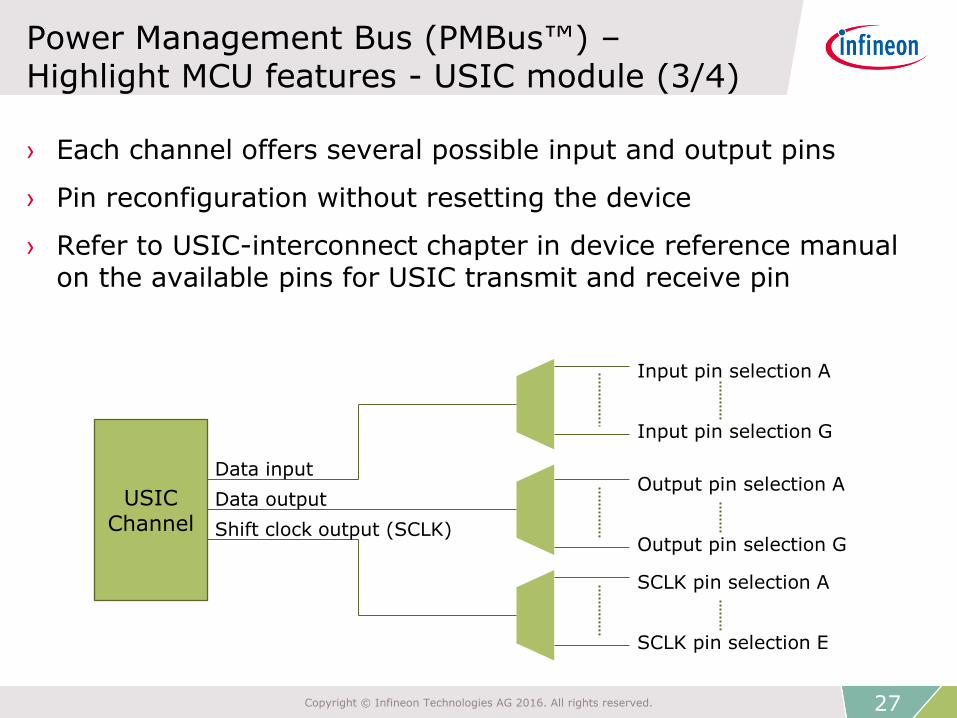
› Each channel offers several possible input and output pins
› Pin reconfiguration without resetting the device
› Refer to USIC-interconnect chapter in device reference manual on the available pins for USIC transmit and receive pin
USIC Channel
Data input
Data output
Shift clock output (SCLK)
Input pin selection A
Input pin selection G
Output pin selection A
Output pin selection G
SCLK pin selection A
SCLK pin selection E
27 Copyright © Infineon Technologies AG 2016. All rights reserved.

Power Management Bus (PMBus™) – Highlight MCU features - USIC module (4/4)
› Interrupts for every protocol
– Transmit shift interrupt (TSI)
– Transmit buffer interrupt (TBF)
– Standard receive interrupt (RI)
– Received start interrupt (RSI)
– Alternative receive interrupt(ARI)
– Data lost interrupt
› I2C protocol related interrupt
– Start condition (START)
– Stop condition (STOP)
– ACK received (ACK)
– NACK received
– Slave read request
– Repeated start condition
START ACK RI/ARI STOP
28 Copyright © Infineon Technologies AG 2016. All rights reserved.

Agenda
Overview
Key features
Specification
System block diagram
Hardware overview
Software overview
Highlight MCU features
Get started
1
2
3
4
5
6
7
8
29 Copyright © Infineon Technologies AG 2016. All rights reserved.

Power Management Bus (PMBus™) – Get started – PMBus™ Lib (1/7)
› Include the library in an existing project
› Configure the library in “xmc_pmbus_common_conf.h”:
1. Chose the available/s channels:
– #define XMC_PMBUS_NODE_USICx_CHy XMC_PMBUS_ENABLE
2. Enable the required library features using the XMC_PMBUS_ENABLE macro:
– Timeout, control signal, smbalert and host notify
3. Configure the length of the slave buffer and microseconds of timeout if required:
– #define XMC_PMBUS_MICRO_SECS (900U)
– #define XMC_PMBUS_SLAVE_MAX_DATA_LENGTH (0x0FU)
30 Copyright © Infineon Technologies AG 2016. All rights reserved.

Power Management Bus (PMBus™) – Get started – PMBus™ Lib (2/7)
› Create XMC_PMBUS_NODE_CONFIG_t for the main slave configuration
Example:
const XMC_PMBUS_NODE_CONFIG_t slave1_config = { /* Channel of the USIC */ .channel = XMC_USIC1_CH1, /* Pointer to initialization structure I2C protocol */ .i2c_config = &slave1_i2c_config, /* Protocol interrupt config*/ .protocol_irq_sr = (uint8_t)XMC_PMBUS_USIC1_CH1_PROTOCOL_IRQ_SR, .protocol_irq_nvic_node = (IRQn_Type)XMC_PMBUS_USIC1_CH1_PROTOCOL_IRQ_NVIC_NODE, .protocol_irq_prio = (uint32_t)XMC_PMBUS_USIC1_CH1_PROTOCOL_IRQ_PRIO, /* RX interrupt */ .rx_fifo_irq_sr = (uint8_t)XMC_PMBUS_USIC1_CH1_RX_FIFO_IRQ_SR, .rx_fifo_irq_nvic_node = (IRQn_Type)XMC_PMBUS_USIC1_CH1_RX_FIFO_IRQ_NVIC_NODE, .rx_fifo_irq_prio = (uint32_t)XMC_PMBUS_USIC1_CH1_RX_FIFO_IRQ_PRIO, /* SCL line config structure */
.scl_pin_config = &pmbus_scl, /*SCL port and pin selection */ .scl_port = XMC_GPIO_PORT0, .scl_pin = 10U,
31 Copyright © Infineon Technologies AG 2016. All rights reserved.

Power Management Bus (PMBus™) – Get started – PMBus™ Lib (3/7)
› Create XMC_PMBUS_NODE_CONFIG_t for the main slave configuration
Example:
/*SCL Input multiplexer selection*/ .scl_source = (uint8_t)USIC1_C1_DX1_P0_10, /* SDA line config structure */ .sda_pin_config = &pmbus_sda, /*SDA port and pin selection */ .sda_port = XMC_GPIO_PORT4, .sda_pin = 2U, /*SCL Input multiplexer selection*/ .sda_source = (uint8_t)USIC1_C1_DX0_P4_2, /* CAPABILITY */ .capability.pec = XMC_PMBUS_DISABLE, .capability.smb_alert = XMC_PMBUS_DISABLE, .capability.max_bus_speed = XMC_PMBUS_SPEED_400KHZ, /* Control signal and timeout disables*/ .control_io_enable = XMC_PMBUS_DISABLE, .timeout_enable = XMC_PMBUS_DISABLE, /* Pointer to the array for received data*/ .data_ptr = slave1_data, };
32 Copyright © Infineon Technologies AG 2016. All rights reserved.

Power Management Bus (PMBus™) – Get started – PMBus™ Lib (4/7)
› Create XMC_PMBUS_NODE_t structure with a pointer to the configuration structure
Example:
XMC_PMBUS_NODE_t slave1 =
{
.config_ptr = &slave_config,
};
› Add the callbacks for the required commands and the extern declarations in “xmc_pmbus_common.c”
Example:
/* Extern declarations */
extern XMC_PMBUS_STATUS_t XMC_PMBUS_NODE_CmdCapability(XMC_PMBUS_NODE_t *const node); extern XMC_PMBUS_STATUS_t XMC_PMBUS_NODE_CmdStatusByte(XMC_PMBUS_NODE_t * const node); extern XMC_PMBUS_STATUS_t XMC_PMBUS_NODE_CmdStatusWord(XMC_PMBUS_NODE_t * const node);
.
.
.
33 Copyright © Infineon Technologies AG 2016. All rights reserved.

Power Management Bus (PMBus™) – Get started – PMBus™ Lib (5/7)
› Add callbacks for required commands and extern declarations in “xmc_pmbus_common.c”
Example: /* Callback functions added to the callback command array */
const XMC_PMBUS_NODE_CMD_INFO_t cmd_info[] =
{
.
.
.
{.call_back = XMC_PMBUS_NODE_CmdCapability, .no_of_data_bytes = 1U, .attribute = (uint16_t)
(XMC_PMBUS_PROTOCOL_RD_BYTE)}, /* Command Code - 19h; Command Name = CAPABILITY*/
.
.
.
{.call_back = XMC_PMBUS_NODE_CmdStatusByte, .no_of_data_bytes = 1U, .attribute = (uint16_t)
(XMC_PMBUS_PROTOCOL_WR_RD_BYTE)}, /* Command Code - 78h; Command Name = STATUS_BYTE*/
{.call_back = XMC_PMBUS_NODE_CmdStatusWord, .no_of_data_bytes = 2U, .attribute = (uint16_t)
(XMC_PMBUS_PROTOCOL_WR_RD_WORD)}, /* Command Code - 79h; Command Name = STATUS_WORD*/
.
.
.
}
34 Copyright © Infineon Technologies AG 2016. All rights reserved.

Power Management Bus (PMBus™) – Get started – PMBus™ Lib (6/7)
› Implements callbacks in application code
Example: /* Capability command callback. It sends back the capabilities of the device*/
XMC_PMBUS_STATUS_t XMC_PMBUS_NODE_CmdCapability(XMC_PMBUS_NODE_t *const node)
{
uint8_t data[2];
XMC_PMBUS_STATUS_t status = XMC_PMBUS_STATUS_ERROR;
if(node->comm_type == XMC_PMBUS_COMM_TYPE_READ)
{
data[0] = node->config_ptr->capability.capability_reg;
XMC_I2C_CH_SlaveTransmit(node->config_ptr->channel, data[0]);
XMC_PMBUS_STATUS_t status = XMC_PMBUS_STATUS_SUCCESS;
}
return (status);
}
35 Copyright © Infineon Technologies AG 2016. All rights reserved.

Power Management Bus (PMBus™) – Get started – PMBus™ Lib (7/7)
› Call Init API at initialization and Task API periodically
Example: int main(void) { . . . /* Init API PMBUS */ XMC_PMBUS_SLAVE_Init(&slave1); . . . while(1U) { /* slave1 task */ XMC_PMBUS_SLAVE_Task(&slave1); } }
36 Copyright © Infineon Technologies AG 2016. All rights reserved.

Agenda
Resource listing 9
37 Copyright © Infineon Technologies AG 2016. All rights reserved.

Power Management Bus (PMBus™) – Resource listing
› PMBus™
– PMBus™ specification Revision 1.2 Part 1
– PMBus™ specification Revision 1.2 Part 2
› PMBus™ Lib
– Documentation
– Dowload library and examples
38 Copyright © Infineon Technologies AG 2016. All rights reserved.

Power Management Bus (PMBus™) – Glossary abbreviations (1/2)
› PMBus™ Power Management Bus
› DAVE™ Free development IDE for XMCTM
› I2C Inter-Integrated Circuit protocol
› PEC Packet Error Checking
› USIC Universal Serial Interface Channel
› NVIC Nested Vectored Interrupt Controller
› ERU Event Request Unit
› GPIO General Purpose Input/Output
› SYSTICK System timer
› FIFO First Input First Output
39 Copyright © Infineon Technologies AG 2016. All rights reserved.

Power Management Bus (PMBus™) – Glossary abbreviations (2/2)
› ACK Acknowledge
› NACK Non-acknowledge
40 Copyright © Infineon Technologies AG 2016. All rights reserved.

The information given in this training materials is given as a hint for the implementation of the Infineon Technologies component only and shall not be regarded as any description or warranty of a certain functionality, condition or quality of the Infineon Technologies component.
Infineon Technologies hereby disclaims any and all warranties and liabilities of any kind (including without limitation warranties of non-infringement of intellectual property rights of any third party) with respect to any and all information given in this training material.
Disclaimer