Embed Size (px)
Citation preview

Power Hawk TM Series 700Console Reference Manual
0830059-000
June 2001

CAUTIONARY NOTICE
While the manufacturer has attempted to detail in this manual all areas of possible danger to personnel in conjunctionwith the use of this equipment, personnel should use caution when installing, checking out, operating and servicingthis equipment, especially when power is on. As with all electronic equipment, care should be taken to avoidelectrical shock in all circuits where substantial currents or voltages may be present either through design or shortcircuit. Caution should be observed in hoisting equipment, especially regarding large structures during installation.
The Manufacturer is specifically not liable for any damage or injury, arising out of a worker’s failure to follow theinstructions contained in this manual, or in his failure to exercise due care and caution in the installation, operation,checkout and service of this equipment.
PROPRIETARY DATA
This document, the design contained herein, the detail and invention are considered proprietary to Concurrent Com-puter Corporation. As the property of Concurrent Computer Corporation it shall be used only for reference, contractor proposal work by this corporation, or for field repair of Concurrent products by Concurrent Computer Corporationservice personnel, customers, or end users.
Copyright 2001 by Concurrent Computer Corporation. All rights reserved. This publication or any part thereof isintended for use with Concurrent products by Concurrent Computer Corporation personnel, customers, and end–users. It may not be reproduced in any form without the written permission of the publisher.
The information contained in this document is believed to be correct at the time of publication. It is subject to changewithout notice. Concurrent Computer Corporation makes no warranties, expressed or implied, concerning theinformation contained in this document.
To report an error or comment on a specific portion of the manual, photocopy the page in question and mark thecorrection or comment on the copy. Mail the copy (and any additional comments) to Concurrent Computer Corpora-tion, 2881 Gateway Drive, Pompano Beach, FL 33069. Mark the envelope “Attention: Publications Department .”This publication may not be reproduced for any other reason in any form without written permission of the publisher.
Night Hawk, Power Hawk, PowerStack II and PowerMAX OS, are trademarks of Concurrent Computer CorporationSynergy, VGM5 and VSS4 are trademarks of Synergy Microsystems, Inc.UNIX is a registered trademark of the Open Group.
Printed in U. S. A.
Revision History: Level: Effective With:
Original Release June 2001 000 New Product Release of Series 700

iii
Preface
Scope of Manual
This manual describes the console for Concurrent Computer Corporation’s Power HawkSeries 700 system. This manual provides information on how to use the console to debugthe system. Series 700 systems use the following single board computers (SBC) manu-factured by Synergy Microsystems, Inc.
Structure of Manual
This manual consists of a title page, this preface, a master table of contents, three chapters,three local tables of contents for the chapters, two appendixes, and an index. A briefdescription of the chapters and appendixes follows:
• Chapter 1 explains where the console fits in a system and describes thehardware of the console.
• Chapter 2 describes what occurs during system initialization and theconsole interface.
• Chapter 3 contains an alphabetical listing of the console debuggingcommands. Each command listing contains the purpose of the command,its syntax, an explanation of the command parameters, and examples of thecommand syntax and usage.
• Appendix A is a quick reference guide that lists the console commands andtheir meanings, as well as an explanation of the command parameters.
• Appendix B lists the possible error codes that may appear executingconsole commands. There is also a short description of the error and apossible cure to the problem.
The index has an alphabetical list of all paragraph formats, character formats, crossreference formats, table formats, and variables.
ConcurrentSystem Platform
Motherboard Type
Number ofProcessors
Form Factor
Power Hawk 710 VGM5 -Single 1 VME 6U
Power Hawk 720 VGM5 - Dual 2 VME 6U
Power Hawk 740 VSS4 - Quad 4 VME 6U

Power Hawk Series 700 Console Reference Manual
iv
Syntax Notation
The following notation is used throughout this guide:
italic Books, reference cards, and items that the user must specifyappear in italic type. Special terms may also appear in italic.
bold User input appears in bold type and must be entered exactly asshown. Names of directories, files, and commands also appear inbold type.
list Operating system and program output such as prompts andmessages and listings of files and programs appears in list type.
[] Brackets enclose command options and arguments that areoptional. You do not type the brackets if you choose to specifysuch option or arguments.
Vendor Documentation
Synergy commercial off-the-shelf (COTS) documentation applicable to the various Synergy Single Board Computers (SBC), are listed below. You may contact your local Synergy sales office to purchase Synergy manuals not provided with the system. See the table below for a list of Synergy manual names and document numbers.
Manual NameSynergy
Document Number
VGM5 Single
Processor SBC
VGM5 Dual
Processor SBC
VSS4 Quad
Processor SBC
VGM5 VMEbus Dual G3/G4 PowerPCSingle Board Computer User Guide
98-0317/UG-VGM5-01
X X -
VSS4 Quad 750 PowerPC VMEbus SingleBoard Computer for DSP User Guide
99-0062/UG-VSS4-01
- - X
SMon PowerPC Series SBCs DevelopersApplication & Debugger User Guide
99-0041/UG-PPSM-01
X X X

v
Chapter 0Contents
Chapter 1 Introduction to the Console
Overview of Console . . . . . . . . . . . . . . . . . . . . . . . . . . . . . . . . . . . . . . . . . . . . . . . . . 1-1
Chapter 2 Startup
System Initialization . . . . . . . . . . . . . . . . . . . . . . . . . . . . . . . . . . . . . . . . . . . . . . . . . 2-1FDIAG Initialization. . . . . . . . . . . . . . . . . . . . . . . . . . . . . . . . . . . . . . . . . . . . . . 2-1SMON Initialization . . . . . . . . . . . . . . . . . . . . . . . . . . . . . . . . . . . . . . . . . . . . . . 2-2Console Initialization . . . . . . . . . . . . . . . . . . . . . . . . . . . . . . . . . . . . . . . . . . . . . 2-4System Boot . . . . . . . . . . . . . . . . . . . . . . . . . . . . . . . . . . . . . . . . . . . . . . . . . . . . 2-5Console Interface . . . . . . . . . . . . . . . . . . . . . . . . . . . . . . . . . . . . . . . . . . . . . . . . 2-7System Entry to Console . . . . . . . . . . . . . . . . . . . . . . . . . . . . . . . . . . . . . . . . . . 2-7VGM5 Reset/SMI Toggle Switch. . . . . . . . . . . . . . . . . . . . . . . . . . . . . . . . . . . . 2-8VSS4 Reset/SMI Toggle Switch. . . . . . . . . . . . . . . . . . . . . . . . . . . . . . . . . . . . . 2-9
Chapter 3 Console Debugging Commands
Summary of Commands . . . . . . . . . . . . . . . . . . . . . . . . . . . . . . . . . . . . . . . . . . . . . . 3-1Syntax Conventions . . . . . . . . . . . . . . . . . . . . . . . . . . . . . . . . . . . . . . . . . . . . . . 3-2Command Format. . . . . . . . . . . . . . . . . . . . . . . . . . . . . . . . . . . . . . . . . . . . . . . . 3-4
Command Specifier. . . . . . . . . . . . . . . . . . . . . . . . . . . . . . . . . . . . . . . . . . . 3-5Data Size and Format . . . . . . . . . . . . . . . . . . . . . . . . . . . . . . . . . . . . . . . . . 3-5Global Options . . . . . . . . . . . . . . . . . . . . . . . . . . . . . . . . . . . . . . . . . . . . . . 3-5Local Options . . . . . . . . . . . . . . . . . . . . . . . . . . . . . . . . . . . . . . . . . . . . . . . 3-6Numeric Values . . . . . . . . . . . . . . . . . . . . . . . . . . . . . . . . . . . . . . . . . . . . . . 3-6Address Value . . . . . . . . . . . . . . . . . . . . . . . . . . . . . . . . . . . . . . . . . . . . . . . 3-6Command Manipulators . . . . . . . . . . . . . . . . . . . . . . . . . . . . . . . . . . . . . . . 3-7
Command Editing. . . . . . . . . . . . . . . . . . . . . . . . . . . . . . . . . . . . . . . . . . . . . . . . 3-9Console Commands. . . . . . . . . . . . . . . . . . . . . . . . . . . . . . . . . . . . . . . . . . . . . . . . . . 3-10
Appendix A Command Summary
Appendix B Error Codes
Illustrations
Figure 2-1. VGM5 Reset and SMI Toggle Switch . . . . . . . . . . . . . . . . . . . . . . . . . 2-6Figure 2-2. VSS4 Reset and SMI Toggle Switch . . . . . . . . . . . . . . . . . . . . . . . . . . 2-7

Power Hawk Series 700 Console Reference Manual
vi
Tables
Table 3-1. Console Debugging Commands - Summary . . . . . . . . . . . . . . . . . . . . . . 3-2Table 3-2. Console Special Key Functions . . . . . . . . . . . . . . . . . . . . . . . . . . . . . . . 3-6Table 3-3. Effect of pboot on Boot Process . . . . . . . . . . . . . . . . . . . . . . . . . . . . . . . 3-22Table 3-4. General–Purpose Registers . . . . . . . . . . . . . . . . . . . . . . . . . . . . . . . . . . . 3-27Table 3-5. Processor Registers Accessed via p Command . . . . . . . . . . . . . . . . . . . 3-34Table 3-6. y Command Flag Bits . . . . . . . . . . . . . . . . . . . . . . . . . . . . . . . . . . . . . . . 3-59Table A-1. Command Parameter Definitions . . . . . . . . . . . . . . . . . . . . . . . . . . . . . . A-8

1Introduction to the Console
Overview of Console . . . . . . . . . . . . . . . . . . . . . . . . . . . . . . . . . . . . . . . . . . . . . . . . . 1-1

Power Hawk Series 700 Console Reference Manual

1-1
1Chapter 1Introduction to the Console
111
Overview of Console 1
The console for the Power Hawk Series 700 system allows the operator to initialize thesystem and perform certain diagnostic procedures. An overview of this product isprovided in the following paragraphs.
The Power Hawk Series 700 system normally begin execution in the SMon program that islocated in flash memory. SMon will then autoboot the Power Hawk Series 700 system con-sole off of the appropriate boot media. The console is provided in a ‘loadable’ format atthe front of bootable media. The SMon internal ROM bootstrap code reads the consoleinto memory, where it then relocates itself to higher memory locations and begins execu-tion.
The exact mode of operation depends upon the operator action and NVRAM settings dur-ing the start-up. If the operator interrupts the boot sequence or has set up NVRAM settingto prevent the boot sequence from autostarting, a console prompt will be output and con-sole commands may be used for debugging or system start-up as described later in thismanual. If the boot is not interrupted, the system bootstrap is fully automatic and thePowerMAX OS kernel will be brought up to the multi-user system level specified in the/etc/inittab file.

Power Hawk Series 700 Console Reference Manual
1-2

2Startup
System Initialization . . . . . . . . . . . . . . . . . . . . . . . . . . . . . . . . . . . . . . . . . . . . . . . . . 2-1FDIAG Initialization. . . . . . . . . . . . . . . . . . . . . . . . . . . . . . . . . . . . . . . . . . . . . . 2-1SMON Initialization . . . . . . . . . . . . . . . . . . . . . . . . . . . . . . . . . . . . . . . . . . . . . . 2-2Console Initialization . . . . . . . . . . . . . . . . . . . . . . . . . . . . . . . . . . . . . . . . . . . . . 2-4System Boot . . . . . . . . . . . . . . . . . . . . . . . . . . . . . . . . . . . . . . . . . . . . . . . . . . . . 2-5Console Interface . . . . . . . . . . . . . . . . . . . . . . . . . . . . . . . . . . . . . . . . . . . . . . . . 2-7System Entry to Console . . . . . . . . . . . . . . . . . . . . . . . . . . . . . . . . . . . . . . . . . . 2-7VGM5 Reset/SMI Toggle Switch. . . . . . . . . . . . . . . . . . . . . . . . . . . . . . . . . . . . 2-8VSS4 Reset/SMI Toggle Switch. . . . . . . . . . . . . . . . . . . . . . . . . . . . . . . . . . . . . 2-9

Power Hawk Series 700 Console Reference Manual

2-1
2Chapter 2Startup
222
System Initialization 2
System initialization can be separated into four distinct areas: FDiag Initialization, SMonInitialization, Console Initialization and System Boot. These occur as described in thefollowing paragraphs. The screen examples shown below are typical. They may vary dueto particular system settings and/or firmware versions.
FDIAG Initialization 2
A Synergy board as shipped from the factory is likely on powerup to stop at the FDiagprompt. FDiag is a ROM-based program from which standalone board diagnostics can beexecuted. An example of a FDIAG boot sequence is shown below.
X: CPU 0 started - User switch = 0x00 X: Y: CPU 1 waiting on consoleX: Hard reset.X: X: Board: VGM5-D ECO: 4 Special Mod. : 0 Serial# : 0000080X: Number of CPUs : 2 Bus Speed (MHz) : 66X: CPU Type : 750 Rev : 8201 Speed : 300MHzX: L2 Cache Size : 1MB Clock Ratio : 1.5:1X: Memory Bank Size : 32MB Number : 4X: Memory Size : 128MB Type : SDRAM, CL=2, RegisteredX: X: Bus Idsel Vendor Device ID Rev Class Sub-Class Part NameX: 0 0 1057 2 40 6 0 Motorola GrackleX: 0 11 1014 46 0 FF 0 IBM MPICX: 0 12 1000 D 2 1 0 Symbios 885 SCSIX: 0 12.1 1000 701 2 2 0 Symbios 885 EthernetX: 0 17 10E3 0 1 6 80 Tundra Universe IIX: 0 18 1011 46 1 6 80 DEC 21554 BridgeX: X: --- Synergy Diagnostics --- Rev: 5.1.6 Apr 28 2000 16:04:04X: X: Starting shell on cpu: 0 Type 'help' for help.FDiag0>

Power Hawk Series 700 Console Reference Manual
2-2
FDIAG can be configured to autoboot the next program in an autoboot sequence, SMon.To configure FDiag to automatically start up SMon you must enter the FDIAG command‘config’ and answer yes (y) to the appropriate question(s) as shown below.
FDiag0> configConsole port baudrate [ 9600]: GDB port (port B) baudrate [115200]: Console is shared [Y]: Built-in self tests enabled [N]: SMon boot enabled [N]: yFDiag0>
SMON Initialization 2
SMon is the Synergy monitor. It can be used to boot, monitor, and debug standaloneprograms, such as an operating system. In Concurrent systems, SMon is used solely toboot the Console, which is the monitor program for all Concurrent systems irrespective ofthe hardware board supplies.
SMon resides in ROM in a compressed form that is not directly executable. It can bedecompressed, written to DRAM, and executed from FDiag by typing SMon, or bypreviously configuring FDiag to autorun SMon whenever the system powers up or isreset. The SMon startup screen will look something like the following:
_______________ _/_/_/ _/ _/ ____________ _/ _/ _/_/ _/_/ _________ _/ _/ _/ _/_/ _/_/_/ _/ _/_/ ______ _/_/_/ _/ _/ _/ _/ _/ _/_/ _/ ____ _/ _/ _/ _/ _/ _/ _/ __ _/ _/ _/ _/ _/ _/ _/ _/ _/_/_/ _/ _/ _/_/_/ _/ _/
SMon Rev: 5.1.6 Apr 28 2000 16:29:08Copyright (c) 1994-2000 Synergy Microsystems.
Synergy VGM5-E PowerPC 750 @ 433 MHz, 66 MHz bus, 128 MB DRAM.--------------------------------------------------------------------BOOT METHOD: ROM-boot SMon stand-alone.HARDWARE PARAMETERS: Bus slave @ 0x20000000, regs @ 0xD0000000.
Bus index 0.TERMINAL SETTINGS: Serial A baud: 9600, Serial B baud: 115200.
Console port: A. Start delay: 5 sec.ETHERNET PARAMETERS: Hardware address: 00:80:f6:00:00:06.
Host: 00.00.00.00 Target: 00.00.00.00Mask: 00.00.00.00 Gateway: 00.00.00.00.
--------------------------------------------------------------------Type 'help' for help.SMon0>
To configure SMon to automatically boot the Console program supplied by Concurrent isa two step process. The first step is to create an SMon startup script and save that inNVRAM. The second step is to turn on autoboot capability. After that, each time SMonstarts up it will run the commands in the previously saved startup script.
Startup
2-3
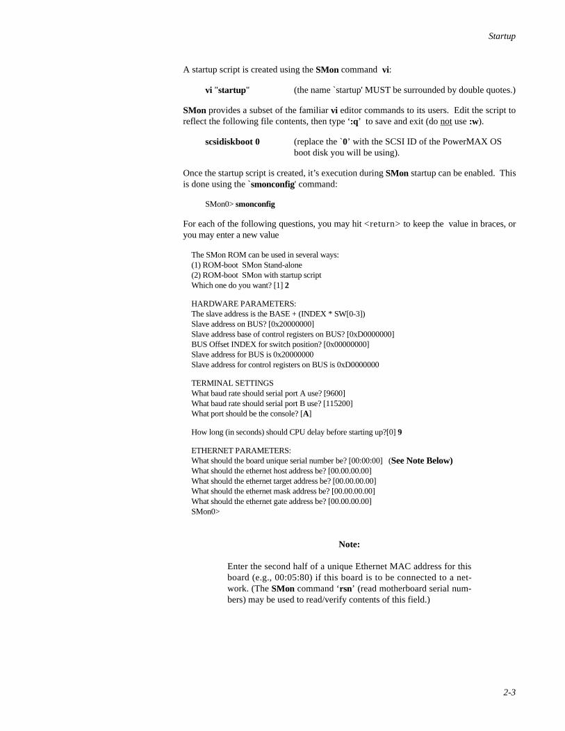
A startup script is created using the SMon command vi:
vi "startup" (the name `startup' MUST be surrounded by double quotes.)
SMon provides a subset of the familiar vi editor commands to its users. Edit the script toreflect the following file contents, then type ‘:q’ to save and exit (do not use :w).
scsidiskboot 0 (replace the 0̀’ with the SCSI ID of the PowerMAX OS boot disk you will be using).
Once the startup script is created, it’s execution during SMon startup can be enabled. Thisis done using the `smonconfig' command:
SMon0> smonconfig
For each of the following questions, you may hit <return> to keep the value in braces, oryou may enter a new value
The SMon ROM can be used in several ways:(1) ROM-boot SMon Stand-alone(2) ROM-boot SMon with startup scriptWhich one do you want? [1] 2
HARDWARE PARAMETERS:The slave address is the BASE + (INDEX * SW[0-3])Slave address on BUS? [0x20000000]Slave address base of control registers on BUS? [0xD0000000]BUS Offset INDEX for switch position? [0x00000000]Slave address for BUS is 0x20000000Slave address for control registers on BUS is 0xD0000000
TERMINAL SETTINGSWhat baud rate should serial port A use? [9600] What baud rate should serial port B use? [115200] What port should be the console? [A]
How long (in seconds) should CPU delay before starting up?[0] 9
ETHERNET PARAMETERS:What should the board unique serial number be? [00:00:00] (See Note Below)What should the ethernet host address be? [00.00.00.00]What should the ethernet target address be? [00.00.00.00]What should the ethernet mask address be? [00.00.00.00]What should the ethernet gate address be? [00.00.00.00]SMon0>
Note:
Enter the second half of a unique Ethernet MAC address for thisboard (e.g., 00:05:80) if this board is to be connected to a net-work. (The SMon command ‘rsn’ (read motherboard serial num-bers) may be used to read/verify contents of this field.)

Power Hawk Series 700 Console Reference Manual
2-4
The critical items in the above run are:
The SMon ROM can be used in several ways: (1) ROM-boot SMon Stand-alone (2) ROM-boot SMon with startup scriptWhich one do you want? [1] 2
and
How long (in seconds) should CPU delay before starting up?[0] 9
In the first answer, we tell SMon we want it to run ‘startup’ at boot time. In the secondanswer, we tell SMon to wait 9 seconds before doing so.
Console Initialization 2
Note
The following assumes the PowerMAX OS has been previouslyinstalled. If the OS has not been installed on your system, pleaserefer to the appropriate version of the Power Hawk Series 700PowerMAX OS Release Notes (Pubs No. 0891084-x.x) forinstallation instructions.
When SMon loads what it thinks is the OS from the boot media, it is actually loading thePowerMAX OS Console software package described in this document. Consoleinitialization consists of determining the console device and selection of debug or systemboot modes. The console normally operates on an ASCII terminal connected to Serial PortA.
The PowerMAX OS Console startup sequence appears as follow:
_______________ _/_/_/ _/ _/ ____________ _/ _/ _/_/ _/_/ _________ _/ _/ _/ _/_/ _/_/_/ _/ _/_/ ______ _/_/_/ _/ _/ _/ _/ _/ _/_/ _/ ____ _/ _/ _/ _/ _/ _/ _/ __ _/ _/ _/ _/ _/ _/ _/ _/ _/_/_/ _/ _/ _/_/_/ _/ _/ SMon Rev: 5.1.6 Apr 28 2000 16:29:08Copyright (c) 1994-2000 Synergy Microsystems.
Synergy VGM5-D PowerPC 750 @ 300 MHz, 66 MHz bus, 128 MB DRAM.----------------------------------------------------------------BOOT METHOD: ROM-boot SMon with startup script.HARDWARE PARAMETERS: Bus slave @ 0x20000000, regs @ 0xD0000000. Bus index 134217728.TERMINAL SETTINGS: Serial A baud: 9600, Serial B baud: 115200. Console port: A. Start delay: 5 sec.ETHERNET PARAMETERS: Hardware address: 00:80:f6:00:00:80. Host: 00.00.00.00 Target: 00.00.00.00 Mask: 00.00.00.00 Gateway: 00.00.00.00.----------------------------------------------------------------

Startup
2-5
To change any of this, hit any key ... 0Executing startup scriptscsi device id=2 READY! probing SCSI... 0 1 2 3 4 5 6 7 8 9 10 11 12 13 143 scsi device(s) foundbooting from disk Unit 1device block size is 0x200Boot Partition starts at 00000000 length 00000347 byte offset 00000000Load image length 00068E00 entry offset 00010000
PowerMAX_OS Synergy Console (5.0-20000712)- Board VGM5-d, 128MB, 2 300MHz PPC-750s each with 1MB L2 Cache, 66MHz bus.- Board options: scsi YES ethernet YES p0-pci YES user burnable flash NO.- CPU 0 stats: chip major rev 2, minor rev 1, chipmaker Motorola. - Boot parms: fd -sw dsk(0,2,0,0), y0, p -sw boot 80, p aboot 9.CPUs 0 1 up. Type `#' to cancel boot, `!' to boot immediately (9 seconds)......
At this point the console waits at most nine seconds before continuing. If an exclamationpoint (!) is entered the console automatically starts the boot sequence without waiting thefull nine seconds. If, however, the operator enters the pound sign (#) during those nineseconds, the system boot procedure is cancelled and the console prompt ‘#>’ is displayed.When the #> prompt is displayed, any command described in Chapter 3 of this manualmay be entered. Of particular importance is the fb command which causes the boot pro-gram to execute and load system programs, and the pboot register command, which spec-ifies the boot options.
The paboot register may also be changed to lengthen or shorten the time, on future auto-boots, the console will wait before autobooting a PowerMAX OS. If paboot is set to zero,autobooting is disabled and the console prompt ‘#>’ is displayed immediately uponconsole startup.
System Boot 2
If the console system boot procedure was not cancelled, then the system boot mode isentered. The boot sequence is as follows:
_______________ _/_/_/ _/ _/ ____________ _/ _/ _/_/ _/_/ _________ _/ _/ _/ _/_/ _/_/_/ _/ _/_/ ______ _/_/_/ _/ _/ _/ _/ _/ _/_/ _/ ____ _/ _/ _/ _/ _/ _/ _/ __ _/ _/ _/ _/ _/ _/ _/ _/ _/_/_/ _/ _/ _/_/_/ _/ _/ SMon Rev: 5.1.6 Apr 28 2000 16:29:08Copyright (c) 1994-2000 Synergy Microsystems.
Synergy VGM5-D PowerPC 750 @ 300 MHz, 66 MHz bus, 128 MB DRAM.-----------------------------------------------------------------BOOT METHOD: ROM-boot SMon with startup script.HARDWARE PARAMETERS: Bus slave @ 0x20000000, regs @ 0xD0000000. Bus index 134217728.TERMINAL SETTINGS: Serial A baud: 9600, Serial B baud: 115200. Console port: A. Start delay: 5 sec.

Power Hawk Series 700 Console Reference Manual
2-6
ETHERNET PARAMETERS: Hardware address: 00:80:f6:00:00:80. Host: 00.00.00.00 Target: 00.00.00.00 Mask: 00.00.00.00 Gateway: 00.00.00.00.-----------------------------------------------------------------
To change any of this, hit any key ... 0Executing startup scriptscsi device id=2 READY! probing SCSI... 0 1 2 3 4 5 6 7 8 9 10 11 12 13 143 scsi device(s) foundbooting from disk Unit 1device block size is 0x200Boot Partition starts at 00000000 length 00000347 byte offset 00000000Load image length 00068E00 entry offset 00010000
PowerMAX_OS Synergy Console (5.0-20000712)- Board VGM5-d, 128MB, 2 300MHz PPC-750s each with 1MB L2 Cache, 66MHz bus.- Board options: scsi YES ethernet YES p0-pci YES user burnable flash NO.- CPU 0 stats: chip major rev 2, minor rev 1, chipmaker Motorola. - Boot parms: fd -sw dsk(0,2,0,0), y0, p -sw boot 80, p aboot 5.CPUs 0 1 up. Type `#' to cancel boot, `!' to boot immediately (9 seconds)......ncr0)0.2.4.......... dsk(0,2,0,0)/. dsk(0,2,0,0)/stand/bootpboot 00000080 PowerMAX OS Boot LoaderBoot : /stand/unix2683832+297207+508045 start 0x4000symbol table loaded
Concurrent PowerMAX_OS Release 5.0
Global Memory: 133935104 bytes
Initialize I/O level 0 interface: SYS.PCI0vp driver initializedncr0: on SYS.PCI0 sym0: on SYS.PCI0
The system is coming up. Please wait.
SCSI device @ID 0 on ncr adapter 0: disk SCSI device @ID 2 on ncr adapter 0: disk SCSI device @ID 4 on ncr adapter 0: cd-romChecking root filesystemNode: zappaChecking /var filesystem
Checking file systems:
File system check complete.
UX:hrtconfig: INFO: /dev/rrtc/0c0 configured as HRT callout queue RTCThe system is ready.
The system's name is zappa.Welcome to Synergy PowerMAX_OS Release 5.0Console Login:

Startup
2-7
The ‘Boot params:’ line in the above example gives real console commands that wereexecuted for you when the console started up. They came from the area of NVRAMreserved for the console. See Chapter 3, Console Debugging Commands, for detaileddescription of these and all the other console commands.
Console Interface 2
Unlike SMon, the console understands several PowerMAX OS filesystem types, andhence is able to reach into and load into memory whatever files the console user desires tobe loaded (see the fl , fr and fb commands). However, the console understands only onefile format - that of a raw, executable image. That is, it is able to load a file bit-for-bit intoa default or designated memory location, and if to be executed, will jump to the loadlocation of the file, in effect assuming that is the first instruction which is to be executed.If the desired file to be executed is not in this format, then a helper program that is in thisformat must first be loaded. One such program is provided with a PowerMAX OSinstallation: /stand/boot. This booter understands the ELF(3E) file format created by thePowerMAX OS cc(1) command. Since the PowerMAX OS kernel is in ELF format,/stand/boot must be used when loading and executing a PowerMAX OS kernel.
/stand/boot is loaded and executed automatically by the fb command. The fB command isidentical to fb except that it allows the operator to specify a different /stand/boot file(assuming one exists). The fl command allows the operator to load a /stand/boot-like filebut not automatically execute it. The fc command gives the operator ls(1)-like listings ofdirectory contents on the root filesystem.
/stand/boot will automatically boot and execute /stand/unix, the actual PowerMAX OSkernel, unless it has been told to ask for an alternate filename to boot, via a pboot flagssetting.
The console makes breakpoint, trace, and other debug services available once aPowerMAX OS kernel, or standalone program such as /stand/boot, has started execu-tion.
System Entry to Console 2
Any entry from a program to the console is performed via exceptions. These exceptionsconsist of breakpoint, trace, halt, and error. Upon entry to the console, the current context,system and user registers, and operating modes are saved and the #> prompt is output.Commands described in Chapter 3 of this manual may then be input. Control is alsotransferred to the console if the operator enters the sequence ‘<CR>~i’ at the systemconsole while the PowerMAX OS kernel is in operation.
Control may be returned to the executing program by entering the r (Run) command. Notethat if File (f) commands are used, it is no longer possible to return to the operating systemat the point it entered the console.

Power Hawk Series 700 Console Reference Manual
2-8
VGM5 Reset/SMI Toggle Switch 2
The VMG5 motherboard has a RESET and SMI toggle switch for each CPU. SeeFigure 2-1.
Figure 2-1. VGM5 Reset and SMI Toggle Switch
RESET Assert either a CPU or board-level RESET as described below.
Pushing a switch to the right asserts a CPU-level RESET to the cor-responding CPU. The CPU-X (top) switch asserts a reset to the CPUon single CPU models and to CPU-X on the dual CPU models. TheCPU-Y switch (bottom) asserts a reset to CPU-Y which has an effectonly on dual CPU models.
Pushing both switches to the right at the same time asserts a board-level reset on all VGM Series models:
• Resets the CPU(s).
• Resets all on-board compo-nents that have such afunction and clears all on-board control registers.
• Asserts a VME RESET ifthe board is serving as theSystem Controller.
SMI Pushing a switch to the left asserts an SMI interrupt to the respectiveCPU.
Pushing the bottom switch to the left has no effect on single processorboards.
Startup
2-9
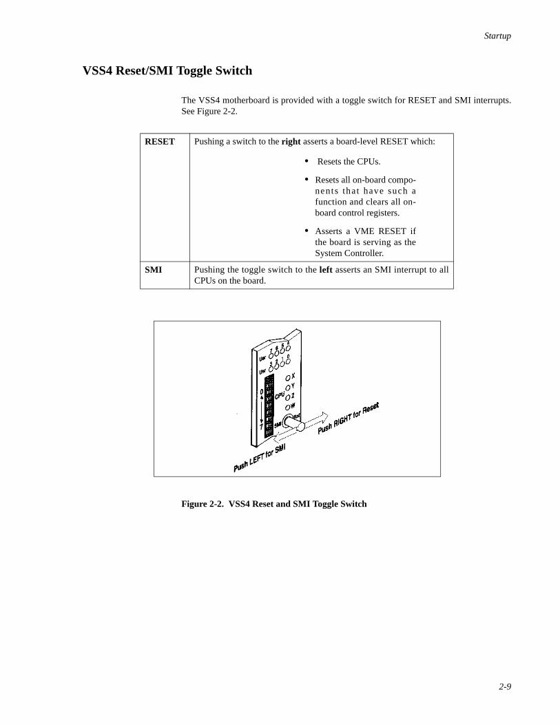
VSS4 Reset/SMI Toggle Switch 2
The VSS4 motherboard is provided with a toggle switch for RESET and SMI interrupts.See Figure 2-2.
Figure 2-2. VSS4 Reset and SMI Toggle Switch
RESET Pushing a switch to the right asserts a board-level RESET which:
• Resets the CPUs.
• Resets all on-board compo-nents that have such afunction and clears all on-board control registers.
• Asserts a VME RESET ifthe board is serving as theSystem Controller.
SMI Pushing the toggle switch to the left asserts an SMI interrupt to allCPUs on the board.

Power Hawk Series 700 Console Reference Manual
2-10

3Console Debugging Commands
Summary of Commands . . . . . . . . . . . . . . . . . . . . . . . . . . . . . . . . . . . . . . . . . . . . . . 3-1Syntax Conventions . . . . . . . . . . . . . . . . . . . . . . . . . . . . . . . . . . . . . . . . . . . . . . 3-2Command Format. . . . . . . . . . . . . . . . . . . . . . . . . . . . . . . . . . . . . . . . . . . . . . . . 3-4
Command Specifier. . . . . . . . . . . . . . . . . . . . . . . . . . . . . . . . . . . . . . . . . . . 3-5Data Size and Format . . . . . . . . . . . . . . . . . . . . . . . . . . . . . . . . . . . . . . . . . 3-5Global Options . . . . . . . . . . . . . . . . . . . . . . . . . . . . . . . . . . . . . . . . . . . . . . 3-5Local Options . . . . . . . . . . . . . . . . . . . . . . . . . . . . . . . . . . . . . . . . . . . . . . . 3-6Numeric Values . . . . . . . . . . . . . . . . . . . . . . . . . . . . . . . . . . . . . . . . . . . . . . 3-6Address Value . . . . . . . . . . . . . . . . . . . . . . . . . . . . . . . . . . . . . . . . . . . . . . . 3-6Command Manipulators . . . . . . . . . . . . . . . . . . . . . . . . . . . . . . . . . . . . . . . 3-7
Command Editing. . . . . . . . . . . . . . . . . . . . . . . . . . . . . . . . . . . . . . . . . . . . . . . . 3-9Console Commands. . . . . . . . . . . . . . . . . . . . . . . . . . . . . . . . . . . . . . . . . . . . . . . . . . 3-10

Power Hawk Series 700 Console Reference Manual

3-1
3Chapter 3Console Debugging Commands
333
Summary of Commands 3
A summary of the console command set is shown in Table 3-1. This command set notonly supports booting, but also the debugging of standalone programs (including thePowerMAX OS kernel) through the use of breakpoint services and the ability to examineand change registers and memory locations on command.
When the console is ready for a new command, it will display one of several prompts:
#>
is displayed for uniprocessor systems.
#0>
is the most common display for multiprocessor systems. The numeric value (0) is theCPU the console is running on (called the master CPU), AND the CPU whose registerswill be examined, modified, or stepped by default when no CPU is specified on thecommand line (the attentive CPU).
#0:1>
This prompt is display when the master CPU (0) is different from the attentive CPU (1).
By default the master CPU is always CPU 0. This can be changed with the tm (configuremaster CPU) command. Sometimes the CPU that is currently the master CPU will bechanged automatically; this can occur for example, if the master CPU ceases to respond.The attentive CPU can be changed with either the tm or the o (global command options)command. When changing the master CPU, be aware that although the console runs finewith any CPU being the master, some booted programs (notably the PowerMAX OSkernel) will not run if booted with any other then CPU 0 being the master.
The console provides an online help facility through the? command. The various forms ofhelp are:
? - a short help overview
?? - a more detailed help overview
?e - help on the ‘e’ command (substitute any other command name for ‘e’)
?- - help on the most common command line options
?* - help on the command line editor

Power Hawk Series 700 Console Reference Manual
3-2
Finally, it is possible to exit the console and restart SMon by executing the <CR>~b com-mand. This command performs a ‘soft reset’ of the system. Other commands are availablethat can reset a system by ‘yanking’ on the various ‘hard reset’ lines. For example,<CR>~h yanks on the VME bus reset line while <CR>~p yanks on the PCI bus reset line.When any of these lines are ‘yanked’, all devices that listen to a given line will undergo ahardware reset. These commands are unique from all others in that they must be precededby a carriage return <CR> in order to be recognized. They can also be typed-in and actedupon by the console while console output is being generated.
Syntax Conventions 3
The following conventions are used in the command syntaxes:
<a> – a is mandatory
[a] – a is optional
a|b – either a or b but not both. The a option or b option can be used with thecommand but the a option cannot be used along with the b option. Note thatthere may be a string of OR options (i.e., a|b|c|d|e ) in this case you canonly have one option, either a or b or c etc.

Console Debugging Commands
3-3
Table 3-1. Console Debugging Commands - Summary
Command Definition See Page No.
a ASCII Dump 3-11
b List Breakpoints 3-14
b Set Breakpoints 3-15
bk Clear Breakpoints 3-16
c Copy Memory 3-17
d Display Memory in Hexadecimal 3-19
di Disassemble Memory 3-22
e Examine/Change Memory 3-23
fb Boot Operating System 3-25
fc Display Directory 3-27
fd Display/Set Default Device 3-28
fh Display Mounted File Systems 3-30
fl Load Program 3-31
fr Load and Execute a Program 3-32
g General Register Display/Modify 3-33
i Initialize Memory to Value (Fill) 3-35
k Kick CPUs 3-37
m Memory Test 3-38
o Global Command Options 3-39
p Processor Register Display/Modify 3-40
qa Query Address 3-43
qb Query Backplane 3-44
qp Display SPR register 3-45
qs Query Stack 3-46
qv Query Virtual Address 3-47
qy Query Current Boot Options 3-48
r Execute Run 3-49
ra Execute Run to Address 3-50
rd Run Without Breakpoints 3-51
rn Run to Next Instruction 3-52
rr Run to Return Address 3-53

Power Hawk Series 700 Console Reference Manual
3-4
Some options are specified by a dash (- ) followed by the option character.Command, options, and data must be entered in lower case. In this manual,parameters which must be entered are enclosed in < > . Optional parametersare enclosed in brackets [] . Optional parameters include such items as endingaddresses for display commands. In general, the command syntax is shownbelow:
command –options start_address ending_address data OR
command –options start_address:byte_count data
Most commands are terminated in one of two ways: by typing a period or by entering acarriage return <CR>. If a command is terminated via a period, the command executesimmediately and then displays the prompt. If the command is terminated via a carriagereturn the command executes and then allows the use of one of the repeater commands.Repeater commands are discussed later in this chapter under the Command Manipulatorsheading.
Command Format 3
Although there is no format common to all the commands described in this chapter, mostof the commands have one or more of the features listed in the sample command shownbelow.
s Search Memory for Data 3-54
sr Search Memory Range for Data 3-56
td Configure CPU Down (multiprocessor SBCs only) 3-57
tm Configure Master CPU 3-58
tu Configure CPU Up (multiprocessor SBCs only) 3-59
w Write Data to Memory 3-60
y Initialize Boot Options/Flags 3-61
z Single–Step Processor 3-62
? Help Command 3-63
Table 3-1. Console Debugging Commands - Summary (Cont.)
Command Definition See Page No.

Console Debugging Commands
3-5
Command Specifier 3
Table 3-1 briefly described each of the console debugging commands. These are the basiccommands without their optional parameters.
Data Size and Format 3
The range of values for formatted data:
b Formatted as a byte – transfers data via eight–bit transfers,
w Formatted as a word (two bytes) – transfers data via 16–bit transfers, or
l Formatted as longwords (four bytes) – transferred in a single 32–bit transfer.This is the default.
r Reverse byte order. Controls byte ordering of 16-bit or 32-bit number. If r isnot specified, byte ordering begins with the highest order byte as Byte 0 (Big-Endian). If r is specified, byte ordering begins with the lowest order byte asByte 0 (Little-Endian). If the ‘r ’ suffix is present, it must follow any ‘b’, ‘ w’,or ‘l ’ suffix that is present.
The data formats described above are depicted in the console command syntaxconventions illustrated in the following example.
e[format][-b<n>][-p|-n][start_address[data]]
Where [format] has the following syntax convention:
[b|w|l][r]
Therefore, for data formats you may specify at most one of b or w or l followed by anoptional r to reverse the retrieval and storage of bytes by the command.
Global Options 3
Some commands look at or can set various global options. See the ‘o’ command on page3-39 for more information on command options).
Data Size
w b r -p . Command Repeater
Command Specifier
Data Format Option Address Representation Data Command Terminator
2 2 .
Power Hawk Series 700 Console Reference Manual
3-6
-b<n> Specify program base address. The base address, represented by the addressvalue n, is added to all addresses entered from the command line. The addressvalue n is zero by default. Numeric address values are discussed later in thischapter.
-c<n> Specify the attentive CPU<n> for this command.
Local Options 3
The following ‘local’ options are commonly available on many commands.
-n<addr>Address arguments are with respect to the NVRAM address space.
-p<addr>Address arguments are with respect to the PCI configuration space.
-s Store into NVRAM when appropriate.
-w When storing into NVRAM, don’t ask ‘are you sure?’.
Numeric Values 3
A numeric value may be entered in any of the following formats.
’cccc’ ASCII value.
hex digits Hexadecimal number.
$ Value of last entered address parameter.
% Contents of the program counter of the default processor.
%regname Contents of the specified processor register of the defaultprocessor.
BnBnBn Hex value of all the specified bits added together (e.g., B2B0 =5) .
[\]symbol Console or program symbol (operating system or diagnostic)name. Leading backslash required when a symbol doesn’t containa leading underscore (_).
Address Value 3
An address may be entered in any of the following formats.
numeric value Physical address by default. If the o+v option is set, andvirtual memory is enabled then the address defaults tovirtual; otherwise, the address is physical.
[numeric value] A physical address is specified by enclosing a numericvalue within square brackets.
Console Debugging Commands
3-7
(numeric value) A virtual address is specified by enclosing a numeric valuewithin parenthesis. The SDR0 and SDR1 registers for theprocessor contain the address of the translation tables.
*numeric value:size An indirect address is specified by placing an asterisk (* )before a numeric value. Note that specifying indirection isvalid only for memory reference options. The optional sizeparameter specifies the size of the indirect memoryreference and must be in the range 1 through 4.
*[numeric value]:size Indirect physical address. The optional size parameterspecifies the size of the indirect memory reference and itmust be in the range 1 through 4.
*(numeric value):size Indirect virtual address. The optional size parameterspecifies the size of the indirect memory reference and itmust be in the range 1 through 4.
Command Manipulators 3
There are two categories of command manipulators: terminators and repeaters. Mostcommands can be terminated (exited) in one of two ways: by pressing the <CR> key or bytyping a period (. ).
If a command line is terminated by typing just a period, the command executesimmediately and then the prompt is displayed, sometimes on the same line as thecommand results. Note that typing another period after the command has terminatedcauses that command to repeat.
If a command line is terminated by pressing the <CR> key, the command executes andthen allows a repeat of the command (or a version of the command) via one of thefollowing repeaters. (Note that not all repeaters are valid for all commands.).
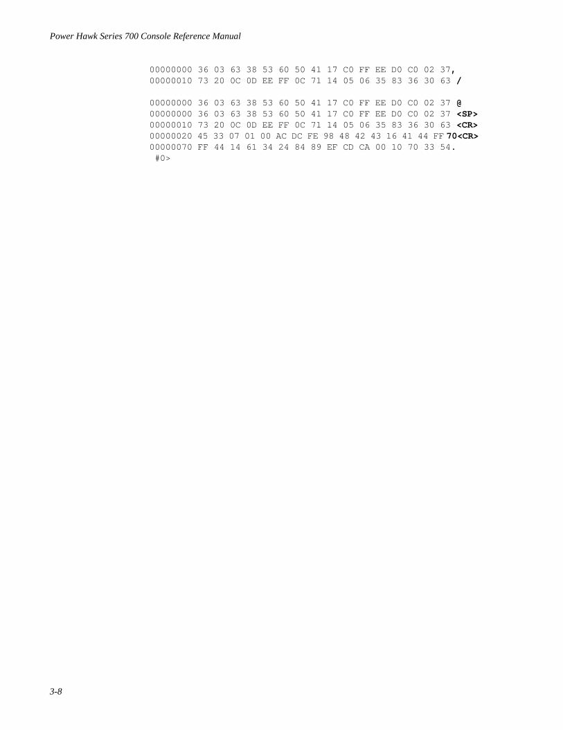
- When a dash (- ) is used as a repeater the current data is displayed in ascii andas binary bits (e.g. B26 B5 B0 ). Note that this repeater is only valid for thee, g, and p commands.
<n><CR> Change address to <n> .
@ Keep same address.
<SP> Increment address to next page.
<CR> Increment address to next line.
/ Decrement address to previous page.
. Repeat or exit current command.
Any command can be aborted by typing CTRL–C. This action causes a soft reset of theconsole. Any commands typed but not yet executed are ignored.
The following example shows the effect of the various command terminators.
#0> db 0:10<CR>
Power Hawk Series 700 Console Reference Manual
3-8
00000000 36 03 63 38 53 60 50 41 17 C0 FF EE D0 C0 02 37 ,00000010 73 20 0C 0D EE FF 0C 71 14 05 06 35 83 36 30 63 /
00000000 36 03 63 38 53 60 50 41 17 C0 FF EE D0 C0 02 37 @ 00000000 36 03 63 38 53 60 50 41 17 C0 FF EE D0 C0 02 37 <SP>00000010 73 20 0C 0D EE FF 0C 71 14 05 06 35 83 36 30 63 <CR> 00000020 45 33 07 01 00 AC DC FE 98 48 42 43 16 41 44 FF 70<CR> 00000070 FF 44 14 61 34 24 84 89 EF CD CA 00 10 70 33 54 . #0>

Console Debugging Commands
3-9
Command Editing 3
Table 3-2 lists the character sequences that you may enter to edit the commands discussedin this chapter.
Table 3-2. Console Special Key Functions
As an aid to the creation of command lines to be executed, the console remembers a number of previously executed command lines and provides their contents for viewing, editing, and possible re-execution. The command line editor functions and their invoking keystrokes are listed below:
CTRL-f , CTRL-b - move forward/backward one character CTRL-a , CTRL-e - move to beginning/end of line del , CTRL-d - delete character under the cursor CTRL-h - delete previous character CTRL-n - move forward to the next input line in the history buffer CTRL-p - move to the previous line in the history buffer CTRL-r , CTRL-l - re-display input line CTRL-k - delete to end of input line CTRL-u - delete entire input line
The console, at all the times it is actually running, monitors all keystrokes entered, looking for special ones that it is to act upon right away. The single-keystroke versions of these are:
CTRL-c - kill the currently running console command, return immediately back to the console prompt. CTRL-s - (XOFF) pause console output display CTRL-q - (XON) restart paused console output display
The console also monitors and acts upon the following keystroke triplets whenever they occur.
<CR>~b - soft reset of only this board. <CR>~p - hard reset of only this board (PCI bus reset) <CR>~h - hard reset of all boards in this rack (VME bus reset on 720 boards; watchdog timer reset on 740 boards) <CR>~o - hard reset of all boards in the rack excluding the board on which this command was executed. Available only to 720 boards which are the VMEbus master controller).
Finally, while not properly the subject of the console, PowerMAX OS watches for several console-like keystroke triplets while it is running:
<CR>~b - soft reset of only this board.<CR>~i - save PowerMAX OS state and enter the console<CR>~k - save PowerMAX OS state, enter the kernel debugger kdb(1) if it has been configured; otherwise enter the console.

Power Hawk Series 700 Console Reference Manual
3-10
Console Commands 3
The remaining part of this chapter describes each of the console commands, with one ormore examples of each command.

Console Debugging Commands
3-11
a ASCII DUMP a
Purpose: This command displays a portion of memory, NVRAM address space or PCIconfiguration space beginning at the specified location. The displayed data isin ASCII format and grouped by byte (b), word (w), or longword (l ). Thiscommand has options (preceded by dashes) which are listed below. For a moredetailed description of the options refer to the options paragraph in this chap-ter.
Syntax: a[format][-b<n>][-p|-n][start_address [end_address]]a[format][-b<n>][-p|-n][start_address[:byte_count]]
format Determines whether the data appears in byte, word, or longword[b, w, or l ] format or is to be byte reversed (r ). If none specified,defaults to byte. (Note that for this command, a size greater than abyte makes little sense.)
-b<n> Specifies program base address. The base address <n> is added toall addresses entered from the command line (<n> is zero bydefault).
-p Address arguments are with respect to the PCI configurationspace.
-n Address arguments are with respect to the NVRAM addressspace.
start_address The hexadecimal address at which the operation starts. Thedefault value is 0.
end_address The hexadecimal address at which the operation ends.
:byte_count Number (in hexadecimal) of bytes displayed. The default is a page(256 bytes). Note that if you specify word format, byte_countshould be a multiple of two. If you specify longword format,byte_count should be a multiple of four.
repeaters See the command manipulators paragraph for explanation.
Examples: The following are valid commands.
a B0 Displays a page of data starting at location B0.
ab 0 Displays a page of data starting at location 0.
al 100:10. Displays the right–most byte of each of the four longwords of datastarting at location 100. In other words, it displays the byte of dataat memory locations 103, 107, 10B, and 10F.
aw 0. Displays right–most byte in each word starting at location 0.
a0. Displays from byte 0.
ab 0 10. Displays contents of addresses 0 through 10.

Power Hawk Series 700 Console Reference Manual
3-12
a ASCII DUMP (Continued) a
Sample ASCII dumps are shown below.
ASCII Dump by Byte with an Initial Address of 0
#0>ab 0. 00000000 H C- 1 . . . . . . . . . . + u 00000010 . . . . . . . . . . T [ . . . . 00000020 . . . . . . . . . d . R C S . 00000030 . . . 0 . . . . . . . . 2 . o . 00000040 . . . @ . . . . . . . . . . . . 00000050 . . . P . . . . . . . . . . + . 00000060 . . . \ . . . . . . . . . . + . 00000070 . . . p . . . . . . . . . . + . 00000080 . . . . . . . . . . . . . . + . 00000090 . . . . . . . . . . T [ . . + . 000000A0 . . . . . . . . . . d . . . + . 000000B0 . . . 0 . . . . . . . . . . + . 000000C0 . . . @ . . . . . . . . . . + . 000000D0 . . . P . . . . . . . . . 1 9 7 000000E0 . . . \ . . . . . . . . . 2 8 9 000000F0 . . . p . . . . . . . . . o . 4
ASCII Dump of Right–Most Byte in Each Word –– Initial Address of 0
#0>aw 0. 00000000 C 1 . . . . . u 00000010 . . . . . [ . . 00000020 . . . . . C . 00000030 . 0 . . . . . . 00000040 . @ . . . . . . 00000050 . P . . . . . . 00000060 . \ . . . . . . 00000070 . p . . . . . . 00000080 . . . . . . . . 00000090 . . . . . [ . . 000000A0 . . . . . . . 000000B0 . 0 . . . . . . 000000C0 . @ . . . . . . 000000D0 . P . . . . 1 7 000000E0 . \ . . . . 2 9 000000F0 . p . . . . o 4

Console Debugging Commands
3-13
a ASCII DUMP (Continued) a
ASCII Dump by Longword
#0> al 0. 00000000 1 . . u 00000010 . . [ . 00000020 . . . . 00000030 0 . . . 00000040 @ . . . 00000050 P . . . 00000060 \ . . . 00000070 p . . . 00000080 . . . . 00000090 . . [ . 000000A0 . . . . 000000B0 0 . . . 000000C0 @ . . . 000000D0 P . . 7 000000E0 \ . . 9 000000F0 p . . 4
ASCII Dump in Various Formats
#0> ab 0 :10. 00000000 H C P 1 . . . . . . . . . . + u #0> ab 0 :4. 00000000 H C P 1 #0> aw 0 :4. 00000000 C 1 #0> al 0 :4. 00000000 1 #0> ab 0 f. 00000000 H C P 1 . . . . . . . . . . + u

Power Hawk Series 700 Console Reference Manual
3-14
b LIST BREAKPOINTS b
Purpose: This command lists breakpoints for all of the processors.
Function: Some of the breakpoint commands have options (preceded by dashes) whichare listed below. For a more detailed description of the options refer to theoptions paragraph in this chapter. Up to eight breakpoint entries are kept in aninternal break address table.
Syntax: b
A sample list breakpoint command is shown below.
#0>b. 00 00001000 CPU physical01 00002000 CPU physical

Console Debugging Commands
3-15
b SET BREAKPOINTS b
Purpose: This command sets breakpoints.
Function: When the processor hits a breakpoint, the console removes the breakpointsfrom memory before accepting any commands. Some of the breakpointcommands have options (preceded by dashes) which are listed below. A moredetailed description of options is provided earlier in this chapter.
Up to eight breakpoint entries are kept in an internal break address table.Overflow of the break address table generates an error message. When aprogram begins executing the system enters the breakpoints into the code.
Syntax: b[-a][-o]<address>
-a Immediately inserts all breakpoints into memory (that is, do notwait until a ‘r ’un command is executed before inserting thebreakpoint set).
-o Breakpoint is temporary. Temporary breakpoints are removedonce they are hit.
address The address to which a breakpoint is assigned. If you want to get abreakpoint at a processor address enter that particular addressafter the b command. If the address is already defined, an errormessage appears on the screen. If the address cannot be written,an error is generated.
Examples: The following are valid commands.
b1000 . Set breakpoint at 0x1000
b hat_icachesync. Set breakpoint at the entry point to the kernel rout ine‘hat_icachesync’.
b.or b<CR > Displays breakpoint

Power Hawk Series 700 Console Reference Manual
3-16
bk CLEAR BREAKPOINTS bk
Purpose: This command clears (removes) breakpoints.
Syntax: bk <address>|<all>
addres s The address to which a breakpoint is assigned. If you want to cleara breakpoint at a processor address enter that particular addressafter the bk command.
all Remove all breakpoints
Examples: The following are valid commands.
bk1000. Remove breakpoint at 0x1000.
bk start Remove the breakpoint at the address when the label “start” is at.
bk all Removes all breakpoints.

Console Debugging Commands
3-17
c COPY MEMORY c
Purpose: This command moves the data located at the source_start_addressthrough source_end_address (inclusive) to the locations starting at thedestination_start_address . This command also moves the datalocated at the source_start_address to the locations starting at thedestination_start_address for the number of bytes specified in thebyte_count . This command has options (preceded by dashes) which arelisted below. See the options paragraph in this chapter for more information.
Note: When virtual addressing is used, translation is performed in ‘data’ space.
Syntax: c[format][-b<n>][-p|-n]<source_sta r t_address><source_end_address><destination_start_address>
c[format][-b<n>][-p|-n]<source_start_address><:byte_count><destination_start_address>
format Determines whether the data is to be copied in byte, word, orlongword [b, w, or l ] format (defaults to l if not specified).Though the byte ordering modifier r can be specified, it isbasically a NOP for this command as the bytes will be reversed oneach read, then re-reversed when written to the new memorylocation.
-b<n> Specifies program base address. The base address <n> is added toall addresses entered from the command line (<n> is zero bydefault).
-p Address arguments are with respect to the PCI configurationspace.
-n Address arguments are with respect to the NVRAM addressspace.
source_start_addressThis is the address at which the memory to be copied starts.
source_end_addressThis is the address at which the memory to be copied stops.
destination_start_addressThis is the destination address.
:byte_count Number (in hexadecimal) of bytes copied. Note that if you specifyword format, byte_count should be a multiple of two. If youspecify longword format, byte_count should be a multiple offour.
Examples: The following are valid commands.
c B0 C0 D0 Moves data at locations B0 through C0 to location D0 .
cb 0 C0 D0 Moves values at locations 0 through C0 to location D0.
Power Hawk Series 700 Console Reference Manual
3-18
c COPY MEMORY(Continued) c
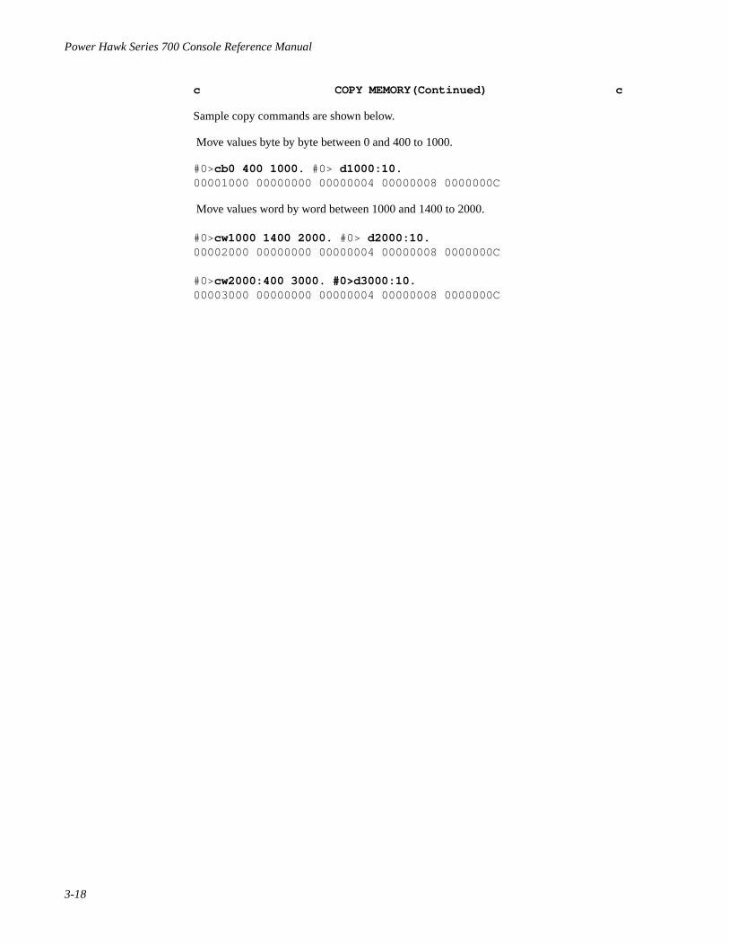
Sample copy commands are shown below.
Move values byte by byte between 0 and 400 to 1000.
#0>cb0 400 1000. #0> d1000:10.00001000 00000000 00000004 00000008 0000000C
Move values word by word between 1000 and 1400 to 2000.
#0>cw1000 1400 2000. #0> d2000:10.00002000 00000000 00000004 00000008 0000000C
#0>cw2000:400 3000. #0>d3000:10.00003000 00000000 00000004 00000008 0000000C
Console Debugging Commands
3-19
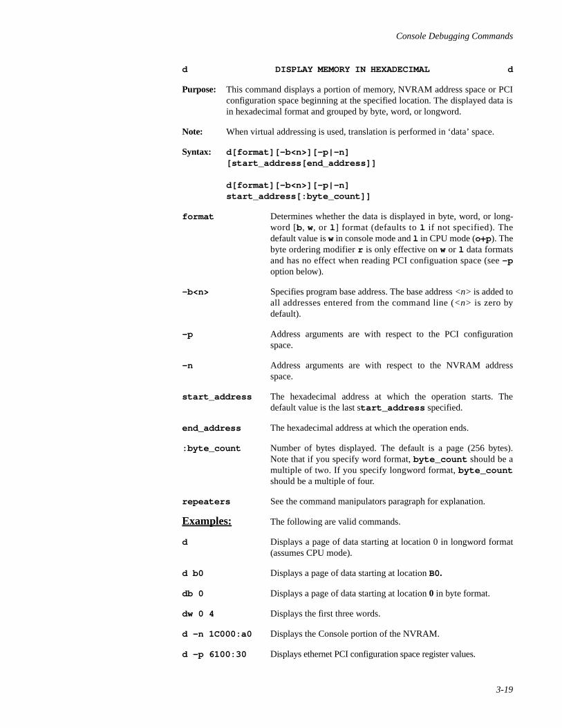
d DISPLAY MEMORY IN HEXADECIMAL d
Purpose: This command displays a portion of memory, NVRAM address space or PCIconfiguration space beginning at the specified location. The displayed data isin hexadecimal format and grouped by byte, word, or longword.
Note: When virtual addressing is used, translation is performed in ‘data’ space.
Syntax: d[format][-b<n>][-p|-n][start_address[end_address]]
d[format][-b<n>][-p|-n]start_address[:byte_count]]
format Determines whether the data is displayed in byte, word, or long-word [b, w, or l ] format (defaults to l if not specified). Thedefault value is w in console mode and l in CPU mode (o+p). Thebyte ordering modifier r is only effective on w or l data formatsand has no effect when reading PCI configuation space (see -poption below).
-b<n> Specifies program base address. The base address <n> is added toall addresses entered from the command line (<n> is zero bydefault).
-p Address arguments are with respect to the PCI configurationspace.
-n Address arguments are with respect to the NVRAM addressspace.
start_address The hexadecimal address at which the operation starts. Thedefault value is the last start_address specified.
end_address The hexadecimal address at which the operation ends.
:byte_count Number of bytes displayed. The default is a page (256 bytes).Note that if you specify word format, byte_count should be amultiple of two. If you specify longword format, byte_countshould be a multiple of four.
repeaters See the command manipulators paragraph for explanation.
Examples: The following are valid commands.
d Displays a page of data starting at location 0 in longword format(assumes CPU mode).
d b0 Displays a page of data starting at location B0.
db 0 Displays a page of data starting at location 0 in byte format.
dw 0 4 Displays the first three words.
d -n 1C000:a0 Displays the Console portion of the NVRAM.
d -p 6100:30 Displays ethernet PCI configuration space register values.

Power Hawk Series 700 Console Reference Manual
3-20
d DISPLAY MEMORY IN HEXADECIMAL (Continued) d
A sample of a hexadecimal memory display is shown below.
HEXADECIMAL DISPLAY BY BYTE STARTING AT ADDRESS 0
#0>db 0.00000000 00 00 00 00 00 00 00 00 00 00 00 00 00 00 AB 7500000010 00 00 00 10 00 00 00 00 1B 9D D4 5B 00 0C 00 0200000020 00 00 00 20 00 00 00 00 1B 9D E4 0C 52 43 53 0000000030 00 00 00 30 00 00 00 00 00 00 00 00 32 2E 6F 0000000040 00 00 00 40 00 00 00 00 00 00 00 00 00 14 00 0800000050 00 00 00 50 00 00 00 00 00 00 00 00 00 00 AB 8D00000060 00 00 00 60 00 00 00 00 00 00 00 00 00 00 AB 8E00000070 00 00 00 70 00 00 00 00 00 00 00 00 00 00 AB 8F00000080 00 00 00 80 00 00 00 00 00 00 00 00 00 00 AB 9000000090 00 00 00 90 00 00 00 00 1B 9D D4 5B 00 00 AB 84000000A0 00 00 00 A0 00 00 00 00 1B 9D E4 0C 00 00 AB 92000000B0 00 00 00 B0 00 00 00 00 00 00 00 00 00 00 AB 93000000C0 00 00 00 C0 00 00 00 00 00 00 00 00 00 00 AB 94000000D0 00 00 00 D0 00 00 00 00 00 00 00 00 00 31 39 37000000E0 00 00 00 E0 00 00 00 00 00 00 00 00 00 32 38 39000000F0 00 00 00 F0 00 00 00 00 00 00 00 00 2E 6F 00 34
HEXADECIMAL DISPLAY BY WORD STARTING AT ADDRESS 1000
#0>dw 1000.00001000 0000 0000 0000 0000 0000 0000 0000 000000001010 0000 0000 0000 0000 0000 0000 1B9E 0E4C00001020 0000 0000 0000 0000 0000 0000 1B9E 0E4C00001030 0000 0000 0000 0000 0000 0000 0000 000000001040 0000 0000 0000 0000 0000 0000 0000 000000001050 0000 0000 0000 0000 0000 0000 0000 000000001060 0000 0000 0000 0000 0000 0000 0000 000000001070 0000 0000 0000 0000 0000 0000 0000 000000001080 0000 0000 0000 0000 0000 0000 0000 000000001090 0000 0000 0000 0000 0000 0000 1B9D CEBB000010A0 0000 0000 0000 0000 0000 0000 1B9E 0E4B000010B0 0000 0000 0000 0000 0000 0000 0000 0000000010C0 0000 0000 0000 0000 0000 0000 0000 0000000010D0 0000 0000 0000 0000 0000 0000 0000 0000000010E0 0000 0000 0000 0000 0000 0000 0000 0000000010F0 0000 0000 0000 0000 0000 0000 0000 0000

Console Debugging Commands
3-21
d DISPLAY MEMORY IN HEXADECIMAL (Continued) d
HEX DISPLAY STARTING AT ADDRESS 1000 –– NO DATA SIZE SPECIFIED
#0>d1000. <––––– Defaults to longword00001000 00000000 00000000 00000000 0000000000001010 00000000 00000000 00000000 1B9E0E4C00001020 00000000 00000000 00000000 1B9E0E4C00001030 00000000 00000000 00000000 0000000000001040 00000000 00000000 00000000 0000000000001050 00000000 00000000 00000000 0000000000001060 00000000 00000000 00000000 0000000000001070 00000000 00000000 00000000 0000000000001080 00000000 00000000 00000000 0000000000001090 00000000 00000000 00000000 1B9DCEBB000010A0 00000000 00000000 00000000 1B9E0E4B000010B0 00000000 00000000 00000000 00000000000010C0 00000000 00000000 00000000 00000000000010D0 00000000 00000000 00000000 00000000000010E0 00000000 00000000 00000000 00000000000010F0 00000000 00000000 00000000 00000000
COMPARE ASCII DISPLAY TO HEXADECIMAL DISPLAY
#0>wl 0 48 43 50 31. #0>ab 0 :10. <–– Write hexadecimal data to memory.00000000 . . . H . . . C . . . P . . . 1#0>al 0 :10.00000000 H C P 1#0>db 0 :10.00000000 00 00 00 48 00 00 00 43 00 00 00 50 00 00 00 31
HEXADECIMAL DISPLAY BY WORD AT ADDRESS 1000
#0>dw 1000:10.00001000 7c51 43a6 3c40 fff0 8842 fe20 5442 07be
HEXADECIMAL DISPLAY BY WORD AT ADDRESS 1000 WITH LITTLE-ENDIAN BYTE ORDERING
#0>dwr 1000:10.00001000 517C a643 403c f0FF 4288 20Fe 4254 be07
HEXADECIMAL DISPLAY BY LONGWORD AT ADDRESS 1000
#0>dl 1000:10.00001000 7c5143a6 3c40fff0 8842fe20 544207be
HEXADECIMAL DISPLAY BY LONGWORD AT ADDRESS 1000 WITH LITTLE-ENDIAN BYTE ORDERING
#0>dlr 1000:10.00001000 a643517c f0ff403c 20fe4288 be074254

Power Hawk Series 700 Console Reference Manual
3-22
di DISASSEMBLE MEMORY di
Purpose: This command disassembles instructions beginning at the specified address.Note that when virtual addressing is used, translation is performed in‘instruction’ space.
Syntax: di[-b<n>][-p|-n][start_address[:byte_count]]
di[-b<n>][-p|-n][start_address [end_address]]
-b<n> Specifies program base address. The base address <n> is added toall addresses entered from the command line (<n> is zero bydefault).
-p Address arguments are with respect to the PCI configurationspace.
-n Address arguments are with respect to the NVRAM addressspace.
start_address The hexadecimal address at which the operation starts. Thedefault value is the last start_address specified.
end_address The hexadecimal address at which the operation ends.
:byte_count Number of bytes displayed. The default is 16 longwords (64bytes).
Sample disassembly commands are shown below. Note that the symbol table must beloaded (bit 7 of register pboot i.e. :#0>pboot 80), and a PowerMAX OS kernel or otherbootable program booted to obtain the symbols shown in this display.
#0>di %pc–10.
000187b4 [000187b4] halt+34 70c31010 andi. r3,r6,1010000187b8 [000187b8] halt+38 7c600124 mtmsr r3000187bc [000187bc] halt+3c 4c00012c isync000187c0 [000187c0] halt+40 4ea00421 bctrl 000187c4 [000187c4] halt+44 % 7cc00124 mtmsr r6000187c8 [000187c8] halt+48 4c00012c isync000187cc [000187cc] halt+4c 7ca803a6 mtlr r5000187d0 [000187d0] halt+50 4ea00020 blr 000187d4 [000187d4] halt+54 48000004 b halt+0x58000187d8 [000187d8] halt+58 48000004 b halt+0x5c000187dc [000187dc] halt+5c 48000004 b consbkpt000187e0 [000187e0] consbkpt 80801ff0 lwz r4,0x1ff0(r0)000187e4 [000187e4] consbkpt+4 2c040000 cmpwi crf0,r4,0000187e8 [000187e8] consbkpt+8 4082000c bne- crf0,consbkpt+0x14000187ec [000187ec] consbkpt+c 38600001 li r3,1000187f0 [000187f0] consbkpt+10 4ea00020 blr
Note that % implies the program counter of the default CPU and * implies break.

Console Debugging Commands
3-23
e EXAMINE/CHANGE MEMORY e
Purpose: This command displays a byte, word, or longword of memory beginning at thespecified memory location, NVRAM address space or PCI configurationspace. This command can also change the data at that location and subsequentlocations via the data specified. The format of the data written is controlled bythe format and command options specified.
Syntax: e[format][-b<n>][-p|-n][start_address[data]]
format Determines whether the data is displayed in byte, word, or long-word [b, w, or l ] format (defaults to l if not specified). Thedefault value is w in console mode and l in CPU mode. The byteordering modifier r is only effective on w or l data formats andhas no effect even then if the -p option is specified.
-b<n> Specifies program base address. The base address <n> is added toall addresses entered from the command line (<n> is zero bydefault).
-p Address arguments are with respect to the PCI configurationspace.
-n Address arguments are with respect to the NVRAM addressspace.
start_address The hexadecimal address at which the operation starts. Thedefault value is 0.
data The new value to be entered at start_address .
repeaters See the command manipulators paragraph for explanation.
Examples: The following are valid commands.
e B0. Displays a longword of data starting at location B0.
eb 0. Displays the byte of data at location 0.
ew0 5. Displays the current word of data at location 0 and then changesthe contents to 5.
Sample examine and change commands are shown below.
EXAMINE ONE BYTE AT ADDRESS 0
#0>eb 0.00000000 00
EXAMINE ONE WORD AT ADDRESS 0
#0>ew 0.00000000 0000

Power Hawk Series 700 Console Reference Manual
3-24
e EXAMINE/CHANGE MEMORY (Continued) e
EXAMINE MEMORY STARTING AT ADDRESS 0 – NO DATA SIZE SPECIFIED
#0>e0 <CR> <–––– Defaults to longword.00000000 00000000, <–––– The comma shows next longword.00000004 AB0007FF. <–––– The period terminates command.
EXAMINE LONGWORD AT LOCATION 1000
#0>e 1000.
00001000 7c5143a6
EXAMINE WORD AT LOCATION 1000
#0>ew 1000.
00001000 7c51
EXAMINE WORD AT LOCATION 1000 IN LITTLE-ENDIAN BYTE ORDERING
#0>ewr 1000.
00001000 517c
EXAMINE WORD WITH VIRTUAL ADDRESS SPECIFIED
#0>e (BFFF8000) <CR> BFFF800 [00018000] 00000000.
DEPOSIT A LONGWORD IN MEMORY AND VERIFY THAT THE VALUE WASSTORED
#0>e10 <CR> 00000010 7FFAB001 50 <––– The user enters 50 and the console writes 50 to
location 10 and verifies that the value is actually00000014 00000432 stored at 10.#0>e10 <CR>00000010 00000050 . <––– The user enters a period.
DEPOSIT A WORD OF DATA WITH THE BYTE PARAMETER
#0>eb 10 <CR> 00000010 00 123@<––– The console displays an error messageerror 0009: memory doesn’t match 0000010 23. <––– The period terminates the command.

Console Debugging Commands
3-25
fb , fB BOOT OPERATING SYSTEM fb , fB
Purpose: This command boots the operating system (OS) of the computer. The contentsof CPU boot register determine how the system boots. Table 3-3 lists the pos-sible values for pboot and the effect of those values on the boot process.
Note: The pboot values can be added together. For example, a value of 1 in pbootcauses the system to prompt for the boot OS file, a value of 2 automaticallyboots the user into single–user mode, and a value of 3 boots into single–usermode and prompts for the boot file. To change the value of CPU boot register,use the p command.
The fb command invokes a helper program /stand/boot which under-stands ELF(3E) file format. The fB command is identical to fb , except withfB the user can specify another helper program in place of /stand/boot .
Syntax: fb [-c<n>][-q]fB [-c<n>][-q] bootfile
-c<n> Specifies the CPU<n> on which the fb or fB command is to runon. If none specified, defaults to the master CPU.
-q Option -q (quick). If set, only one attempt is made to find the/stand/boot or specified file system.
bootfile The filename of the helper boot program to be used, by default,/stand/boot is used. (This option is generally reserved fordevelopers who are creating their own ‘/stand/boot’ programs fordevelopment purposes.)
Table 3-3. Effect of pboot on Boot Process
pboot Value (Hex)
Effected File Effect on Boot Process
0 Boots automatically without option.
1 /stand/boot Requests file name for boot. Asks user to specify theprogram to load.
2 unix Boots OS to single–user mode.
4 unix Do not synchronize before reboot.
8 unix Do not reboot, just halt
80 unix Debug option (load symbol table).
100 unix Load OS and then halt. If resumed, the OS will halt againafter enabling Virtual Memory.
400 unix Load then halt in kernel debugger
800 unix Do not initialize kernel debugger.

Power Hawk Series 700 Console Reference Manual
3-26
fb , fB BOOT OPERATING SYSTEM (Continued) fb , fB
A sample system boot listing is shown below.
#0> fb <CR> dsk(3,0,0,0)/. Initialize VME dsk(3,0,0,0)/stand/boot
Boot : unix 747336+61360+597388 start 0x4000

Console Debugging Commands
3-27
fc DISPLAY DIRECTORY fc
Purpose: This command lists the contents of the specified directory.
Note: Never append a period to this command. After the command, you must press<CR>. (Periods are valid syntax in pathnames.)
Syntax: fc [dir_name]
dir_name A directory name. If the m option of the o command is set (o+m)you must provide the device on which the directory is located.
Examples: The following are valid commands.
fc/usr/d <CR>
fc/ <CR>
A sample root directory listing is shown below.
#0> fc / <CR>
.
.. lost+found usr var
tmp dev sbin etc
unix bck bin export
home install installr lib
mnt opt proc save
shlib stand system .profile
boot idle spare tmp_rex
.sh_history x.c x

Power Hawk Series 700 Console Reference Manual
3-28
fd DISPLAY/SET THE DEFAULT DEVICE fd
Purpose: This command sets or displays the default device.
Note: Never append a period to this command. After the command, you must press a<CR>. (Periods are valid syntax in parameters.)
Syntax: fd [-l][-s[w]][dev]
-l List the logical device table. If this option is entered, do not enterdev . This option displays all of the available boot devices (tapesand disks) along with the logical device numbers. See examplesbelow.
-s In addition to changing the default device locally, also save theselection in NVRAM. This makes the selection available acrosssystem resets to all future boots.
-w If saving to NVRAM, don’t ask ‘are you sure?’.
dev The device that is to be chosen as the default device. Two formatsare available depending upon the number of fields in dev. Thetwo field version is either dsk(d,p) or mt(d,p) where d is alogical device number and p is the partition number (0 through 6).Logical device numbers always run from 0 to n and correspond tothe available boot devices found by the system during a search ofall available SCSI controllers. The table of logical device numbersmay be displayed via the -l option. The second format for devprovides an absolute hardware address and is input asdsk(c,u,p,b) or mt(c,u,p,b) where c is the controllernumber within the particular bus, u is the drive ID, p is thepartition number (0 through 6) and b is the bus number (0 isnormally the internal PCI bus, 1 is the VME bus and 2 is the IDEbus). To use the absolute mode, all four fields must always beentered. If you do not specify a device, the console assumes thetwo field version and selects dsk(0,0).
Examples: The following are valid commands.
fd mt(0) Set the default device to the first tape device found on the variousSCSI bus controllers in the system. Partition zero is selected bydefault.
fd dsk(0,0,0,0 ) Set the default device to the disk on SCSI ID 0 of the internal PCIbus SCSI controller.
fd dsk(0,0,2,0) Set default to ‘usr’ partition.

Console Debugging Commands
3-29
fd DISPLAY/SET THE DEFAULT DEVICE (Continued fd
fd -l List the available devices and logical device numbers:
>fd -l------------------------------------------------------------------fd disk tape0 (2,0,x,1) FUJITSU M2624S-512(0,5,x,0) ARCHIVE VIPER 150 212471 (2,2,x,1) FUJITSU M2624F-512------------------------------------------------------------------
Examples using the -s option:
The following are valid commands using the -s option.
fd -s with no parameters specified, clears the default device
fd -s dsk(1) causes the second disk listed under fd-l to be used as the defaultboot device on subsequent system boots.
Example of changing the default disk from drive 0 to drive 1:
#0>fd .............................. dsk(0,0,0,0) #0>fd -s dsk(1) Update NVRAM (Y/N) ? y| NVRAM updated
Example of reverting back to drive 0 (default):
#0>fd -s Clearing default boot device. Update NVRAM (Y/N) ? y NVRAM updated.

Power Hawk Series 700 Console Reference Manual
3-30
fh DISPLAY MOUNTED FILE SYSTEMS fh
Purpose: This command gives the default input device.
Note: Never append a period to this command. After the command, you must press<CR>. (Periods are valid syntax in parameters.)
Syntax: fh
A sample display from the fh command is shown below.
#0> fh <CR> Default: dsk (5,0,0,0)
Console Debugging Commands
3-31
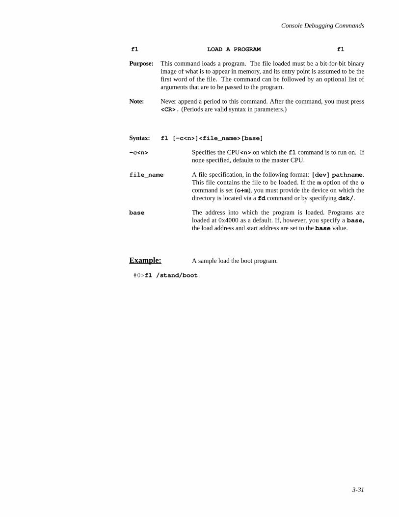
fl LOAD A PROGRAM fl
Purpose: This command loads a program. The file loaded must be a bit-for-bit binaryimage of what is to appear in memory, and its entry point is assumed to be thefirst word of the file. The command can be followed by an optional list ofarguments that are to be passed to the program.
Note: Never append a period to this command. After the command, you must press<CR>. (Periods are valid syntax in parameters.)
Syntax: fl [-c<n>]<file_name>[base]
-c<n> Specifies the CPU<n> on which the fl command is to run on. Ifnone specified, defaults to the master CPU.
file_name A file specification, in the following format: [dev] pathname .This file contains the file to be loaded. If the m option of the ocommand is set (o+m), you must provide the device on which thedirectory is located via a fd command or by specifying dsk/ .
base The address into which the program is loaded. Programs areloaded at 0x4000 as a default. If, however, you specify a base ,the load address and start address are set to the base value.
Example: A sample load the boot program.
#0> fl /stand/boot

Power Hawk Series 700 Console Reference Manual
3-32
fr LOAD AND EXECUTE A PROGRAM fr
Purpose: This command loads and executes a program. The file loaded must be a bit-for-bit binary image of what is to appear in memory, and its entry point isassumed to be the first word of the file. The command can be followed by anoptional list of arguments that are to be passed to the program.
Note: Never append a period to this command. After the command, you must press<CR>. (Periods are valid syntax in parameters.)
Syntax: fr [-c<n>]<file_name>[base]
-c<n> Specifies the CPU<n> on which the fr command is to run on. Ifnone specified, defaults to the master CPU.
file_name A file specification, in the following format: [dev] pathname .This file contains the file to be loaded. If the m option of the ocommand is set (o+m), you must provide the device on which thedirectory is located via a fd command or by specifying dsk/ .
base The address into which the program is loaded. Programs areloaded and run at 0x4000 as a default. If, however, you specify abase , the load address and start address are set to the basevalue.
Example: A sample load the boot program and boot the system sequence isshown below.
#0> fr /stand/boot <CR>
Boot : /stand/unix2683832+297207+508045 start 0x4000symbol table loaded
Concurrent PowerMAX_OS Release 5.0

Console Debugging Commands
3-33
g GENERAL REGISTER DISPLAY/MODIFY g
Purpose: This command displays and/or modifies the contents of the 40 general–purpose registers of the default CPU as shown in Table 3-4. If no parametersare specified, this command displays all of the general purpose registers (e.g.pc, r0 through r3, etc.). If a register name with no data parameter is speci-fied, the contents of that specific register is displayed. If the data parameteris included, the console changes the value in the register. Subsequent registerscan be modified by specifying new data for that particular register. To displaythe registers, the CPU must be halted. After the CPU is halted, the data dis-played is that obtained at the last CPU halt.
Note: This command is identical to the p command, except that if no register list isspecified, the default set of registers listed is different.
Syntax: g [-c<n>]<register_name>[data]
-c<n> Specifies the CPU<n> on which the command is to run on. Ifnone specified, defaults to the attentive CPU.
register_name The general–purpose register to be examined or changed.
data The new hexadecimal value to be entered at register_name.
repeaters See the command manipulators paragraph for explanation.
Table 3-4. General–Purpose Registers
REGISTER N ACRONYM TYPE
Program Counter pc R/W
Machine Status Register msr R/W
Register 0 r0 R/W
Register 1 r1 R/W
. . .
. . ,
. . .
Register 31 r31 R/W
Condition Register cr R/W
Link register lr R/W
Count Register ctr R/W
Extension Register xer R/W
System CPU Level spl R/W

Power Hawk Series 700 Console Reference Manual
3-34
g GENERAL REGISTER DISPLAY/MODIFY (Continued) g
Examples: The following are valid commands.
gpc. Display contents of the program counter.
gr1. Display contents of data register r1.
g. Displays contents of all general registers.
An examine all general register values example is shown below.
#0>gpc = 000187C4 msr = 00001010 cr = 48800000 spl = 00000061
r0 = 0000F084 r1 = FFD040B8 r2 = 00000000 r3 = 00001010
r4 = 00002000 r5 = 0021E554 r6 = 00009032 r7 = C22DE4F5
r8 = 00000001 r9 = 00000001 r10 = 002F2D19 r11 = 002F2D19
r12 = C22DE475 r13 = 0021E140 r14 = 002F2D19 r15 = 00000069
r16 = 003EFE48 r17 = 00000069 r18 = 00000069 r19 = 00000000
r20 = 00000001 r21 = FFD041FA r22 = 00000001 r23 = 00000061
24 = 0000006C r25 = 00009032 r26 = 00000000 r27 = 00000094
r28 = DEADBEEF r29 = 00000020 r30 = 81818181 r31 = 0BADC0DE
lr = 000187C4 ctr = 01FC7ED8 xer = 00000004
An examine and change register values example is shown below.
#0> gr1 <CR> <––––Displays contents of register r1. r1 = C002F7F2, <––––Entering the comma displays r2. r2 = 00000000, <––––Entering the comma displays r3. r3 = 81A40001 <––––Entering the period finishes command. #0> gr2 23.81A40001 <––––Change contents of r2 to 23. #0> gr1 <CR> <––––Display register r1. r1 = C002F7F2 r2 = 00000000, r3 = 00000023.

Console Debugging Commands
3-35
i INITIALIZE MEMORY TO VALUE (FILL) i
Purpose: This command writes the data into all locations between thestart_ad dress and end_address . The format of the data is controlledvia the options entered. Memory addresses before 0x6000 are used by theconsole and should not be initialized.
Note: When virtual addressing is used, translation is performed in ‘data’ space.
Syntax: i[format][-b<n>][-p|-n]<start_address><end_address> [fill_value]
i[format][-b<n>][-p|-p]<start_address>:<byte_count> [fill_value]
format Determines whether the data is displayed in byte, word, or long-word [b, w, or l ] format (defaults to l if not specified). Thedefault value is w in console mode and l in CPU mode.The byteordering modifier r is only effective on w or l data formats. The rmodifier flag has no effect if the -p option is also specfied.
-b<n> Specifies program base address. The base address <n> is added toall addresses entered from the command line (<n> is zero bydefault).
-p Address arguments are with respect to the PCI configurationspace.
-n> Address arguments are with respect to the NVRAM addressspace.
start_address The address at which the loading of memory starts. This addressmay not be a virtual address.
end_address The address at which the loading of memory ends. If theend_address is not supplied or is a location before the start_address , you get a syntax error. This address may not be avirtual address.
:byte_count Number (in hexadecimal) of bytes initialized. Note that if youspecify word format, byte_count should be a multiple of two.If you specify longword format, byte_count should be amultiple of four.
fill_value The hexadecimal word that is loaded into each memory location.The fill value defaults to zero.

Power Hawk Series 700 Console Reference Manual
3-36
i INITIALIZE MEMORY TO VALUE (FILL) (Continued) i
Examples: The following are valid commands.
i b -n 1C000:10 0Fill with zero part of the console area of the NVRAM.
i10 20 10101010. Loads each longword from 10 to 20 with the hexadecimal word10101010.
ib10 20 F. Loads each byte from 10 to 20 with the hexadecimal value F.
Sample memory initialization procedures are shown below.
INITIALIZE MEMORY BETWEEN ADDRESSES 1000 AND 2000
#0> i1000 2000 10101010. #0>d1000 :10. <–– Defaults to longword hexadecimal display starting at address 1000.
00001000 10101010 10101010 10101010 10101010
INITIALIZE MEMORY BETWEEN ADDRESSES 1000 AND 2000 (LOAD A WORD)
#0> iw1000 2000 ff. #0>d1000:10.
00001000 00FF00FF 00FF00FF 00FF00FF 00FF00FF
INITIALIZE MEMORY BETWEEN ADDRESSES 10 AND 20 (LOAD A BYTE)
#0> ib10 20 f. #0>d10:10.
00000010 0F0F0F0F 0F0F0F0F 0F0F0F0F 0F0F0F0F

Console Debugging Commands
3-37
k Kick CPUs k
Purpose: This command is used on multiprocessor systems to kick nonresponsive CPUsback into the console.
A CPU may be nonresponsive, for example, if it has blocked out interrupts.
The ‘k ’ command functions by resetting (yanking on the SysReset pin) of theerrant CPUs. There is always the risk the application state of “kicked” CPUsmay be lost.
Syntax: k
Examples:
k

Power Hawk Series 700 Console Reference Manual
3-38
m MEMORY TEST m
Purpose: This command performs a combination of tests (ones, zeroes, and uniqueaddress) that checks memory, NVRAM address space or PCI configurationspace between the start_address and end_ad dress . Any errorswhich occur appear listed on the console screen.
Note: When virtual addressing is used, translation is performed in ‘data’ space.
Syntax: m[format][-b<n>][-p|-n][start_address][end_address>
m[format][-b<n>][-p|-n][start_address][:byte_count]
format: Determines whether the data is displayed in byte, word, or long-word [b, w, or l ] format (defaults to l if not specified). The byteordering modifier r is only effective on w or l data formats.
-b<n> Specifies program base address. The base address <n> is added toall addresses entered from the command line (<n> is zero bydefault).
-p Address arguments are with respect to the PCI configurationspace.
-n Address arguments are with respect to the NVRAM addressspace.
start_address The first address tested. This address may not be a virtual address.
end_address The last address tested. This address may not be a virtual address.
:byte_count Number (in hexadecimal) of bytes tested. Note that if you specifyword format, byte_count should be a multiple of two. If youspecify longword format, byte_count should be a multiple offour.
Example: The following is a valid command.
m1000 2000.

Console Debugging Commands
3-39
o GLOBAL COMMAND OPTIONS o
Purpose: This command sets conditions under which the console operates. Theseconditions are stored as options in an options word.
Syntax: o [+|-][a][m][v][-b<n>][-c<n>]
+ or - A plus (+) adds and a minus (- ) removes the specified optionsfrom the options word, effectively enabling or disabling thatoption. If you do not use a plus or minus, the command sets theoptions word to the options specified. The options are theconditions under which the console operates. If you do not specifyany options, the console displays the current options.
a Permit auto-rebooting of kernel on certain PowerMAX OSfailures.
m Disables automatic translation and ‘mount’ of directory names tothe corresponding file system devices. These devices allow systemfiles to be available from the console across all system disks bysystem–wide pathnames.
v Defaults to virtual addresses whenever virtual memory is enabled.Brackets or parentheses may be used to override the defaultaddress mode.
-c<n> Change the attentive CPU to CPU<n>.
-b<n> Specifies program base address. The base address <n> is added toall addresses entered from the command line (<n> is zero bydefault).
Examples: The following are valid commands.
o. Display options that are set.
o+r Add r option.
o-vm Disable v and m options.
Sample set and remove options commands are shown below.
#0>o. <––––Display current options.mr -b 0
#0>o+v. <–––– Add v option.o. mrv -b 0

Power Hawk Series 700 Console Reference Manual
3-40
p PROCESSOR REGISTER DISPLAY/MODIFY p
Purpose: This command displays and changes the contents of the 44 processor registersand the two pseudo-registers ‘boot’ and ‘aboot’ (see Table 3-5). If no parame-ters are specified, this command displays all of the processor registers. If aregister name with no data is given, the contents of the specified register is dis-played. If you specify the data parameter, the console changes the value in theregister to the value specified. Processor registers and their attributes werediscussed under the processor registers paragraph in this manual.
Note: This command is an alternative version of the g command.
Syntax: p [-c<n>][<register_name>[data]] p [-s[w] boot <flags> paboot<seconds>
-c<n> Specifies the CPU<n> on which the command is to run on. Ifnone specified, defaults to the master CPU.
register_name The processor register to be examined or changed. The value ofthe register_name is the symbolic register name.
data The hexadecimal data to be placed in the processor register.
seconds Where ‘seconds’ is the number of seconds to delay when autoboot-ing an OS.
flags pboot values shown in Table 3-3 on 3-25. Values can be addedtogether.
Note: The pseudo-registers ‘boot’ and ‘aboot’ are not real machineregisters; they are memory locations within the console which canbe viewed and/or changed with the ‘p’ command.
Examples: The following are valid commands.
p. Displays all processor registers.
pboot Displays contents of processor boot register (see fb command).
pdar. Displays contents of the Data Address Register.
An examine all processor register values example is shown below.
#0>p.
dsisr = 0A000000 dar = 3003B288 sdr1 = 01E0000F fpscr = 000000D0 sr0 = 20000000 sr1 = 20DE2989 sr2 = 20DE298A sr3 = 20DE298B sr4 = 20DE298C sr5 = 20DE298D sr6 = 20DE298E sr7 = 20DE298F sr8 = 20DE2990 sr9 = 20DE2991 sr10 = 20DE2992 sr11 = 20DE2993 sr12 = 20DE2994 sr13 = 20DE2995 sr14 = 20000001 sr15 = 20000002 sprg0 = 002F0000 sprg1 = 20DEE9DE sprg2 = FFD05000 sprg3 = FFD04400 ibat0u = 0000007E ibat1u = 00000000 ibat2u = 00000000 ibat3u = 00000000 ibat0l = 00000003 ibat1l = 00000000 ibat2l = 00000000 ibat3l = 00000000 dbat0u = 0020003E dbat1u = 00000000 dbat2u = 00000000 dbat3u = 00000000 dbat0l = 00200012 dbat1l = 00000000 dbat2l = 00000000 dbat3l = 00000000 dabr = 00000000 iabr = 00000000 hid0 = 00000000 l2cr = 00000000 boot = 00000982 aboot = 00000000
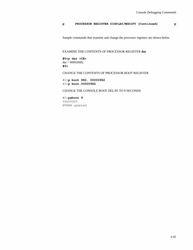
Console Debugging Commands
3-41
p PROCESSOR REGISTER DISPLAY/MODIFY (Continued) p
Sample commands that examine and change the processor registers are shown below.
EXAMINE THE CONTENTS OF PROCESSOR REGISTER dar
#0>p dar <CR>dar = 00002000,#0>
CHANGE THE CONTENTS OF PROCESSOR BOOT REGISTER
#0>p boot 982. 00000982#0>p boot.00000982
CHANGE THE CONSOLE BOOT DELAY TO 9 SECONDS
#0>paboot 900000009NVRAM updated
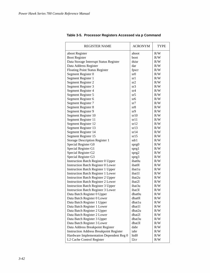
Power Hawk Series 700 Console Reference Manual
3-42
Table 3-5. Processor Registers Accessed via p Command
REGISTER NAME ACRONYM TYPE
aboot RegisterBoot RegisterData Storage Interrupt Status RegisterData Address RegisterFloating Point Status RegisterSegment Register 0Segment Register 1Segment Register 2Segment Register 3Segment Register 4Segment Register 5Segment Register 6Segment Register 7Segment Register 8Segment Register 9Segment Register 10Segment Register 11Segment Register 12Segment Register 13Segment Register 14Segment Register 15Storage Description Register 1Special Register G0Special Register G1Special Register G2Special Register G3Instruction Batch Register 0 UpperInstruction Batch Register 0 Lower Instruction Batch Register 1 UpperInstruction Batch Register 1 LowerInstruction Batch Register 2 UpperInstruction Batch Register 2 Lower Instruction Batch Register 3 UpperInstruction Batch Register 3 LowerData Batch Register 0 UpperData Batch Register 0 LowerData Batch Register 1 UpperData Batch Register 1 LowerData Batch Register 2 UpperData Batch Register 2 LowerData Batch Register 3 UpperData Batch Register 3 LowerData Address Breakpoint RegisterInstruction Address Breakpoint RegisterHardware Implementation Dependent Reg 0L2 Cache Control Register
abootbootdsisrdarfpscrsr0sr1sr2sr3sr4sr5sr6sr7sr8sr9sr10sr11sr12sr13sr14sr15sdr1sprg0sprg1sprg2sprg3ibat0uibat0libat1uibat1libat2uibat2libat3uibat3ldbat0udbat0ldbat1udbat1ldbat2udbat2ldbat3udbat3ldabriabrhid0l2cr
R/WR/WR/WR/WR/WR/WR/WR/WR/WR/WR/WR/WR/WR/WR/WR/WR/WR/WR/WR/WR/WR/WR/WR/WR/WR/WR/WR/WR/WR/WR/WR/WR/WR/WR/WR/WR/WR/WR/WR/WR/WR/WR/WR/WR/WR/W

Console Debugging Commands
3-43
qa QUERY ADDRESS qa
Purpose: This command allows either the symbolic name of a specified address or theaddress of a specified symbolic name to be queried. The symbols table musthave been previously loaded by setting bit 7 in the pboot register (e.g. pboot80. ) and issuing a fb command.
Syntax: qa<address>
address The address for which a symbol name is to be displayed.
Example: The following are valid commands.
#0>qa C0066000 <CR> hdioctl+2A0 (C0065D60+2A0)
#0>qa \hdioctl <CR> hdioctl (C0065D60)

Power Hawk Series 700 Console Reference Manual
3-44
qb QUERY BACKPLANE qb
Purpose: This command displays processor status information.
Syntax: qb
A sample display from the qb command is shown below.
#0> qb cpu alive down runable halted stuck --- ----- ---- ------- ------ ----- 0 y - - y - master attentive 1 y - - y -
Note:
alive CPU is available for applications to use
down user has marked CPU as unavailable
runable CPU has application state associated with it
halted CPU is idling in or executing Console code
stuck CPU is stuck in uninterruptable application code
master CPU Console does its best to run on
attentive CPU whose application state Console is focused on

Console Debugging Commands
3-45
qp DISPLAY SPECIAL PURPOSE REGISTERS qp
Purpose: Displays the actual values of either every special purpose (SPR) register ofsome CPU, or displays selected SPRs across all CPUs.
Syntax: qp [-c<n>]
qp reg reg ...
-c<n> Specifies the CPU<n> whose entire SPR register set is to bedisplayed.
Examples: The following are valid commands.
qp -c0 Display s all the SPRs for CPU 0.
qp msscr0 msscr1 Displays the value of these two SPRs for all CPUs.
Note: A special purpose register is any register given a SPR number by the PowerPCArchitecture and can be referenced by the mtspr and mfspr instructions. This setincludes some rather common registers, such as CTR lR, which are also reportedby other console commands such as ‘g’ and ‘p’.

Power Hawk Series 700 Console Reference Manual
3-46
qs QUERY STACK qs
Purpose: This command displays the stack of a program that has been booted by theconsole. The stack of the attentive CPU is displayed.
Syntax: qs[-c<n>]
-c<n> Specifies the CPU<n> whose stack is to be displayed. If nonespecified, defaults to the attentive CPU.
Examples: The following is a valid command.
#0>qs.
––––––––– KERNEL STACK –––––––––
_cnputs() at C00639E6(_cnputs+6)BFFFE9E2 _cnproc() at C0063908(_cnproc+200)BFFFEA46 _ttwrite() at C006ACDA(_ttwrite+31E)BFFFEA8A _raw_rw() at C0050416(_raw_rw+526)BFFFEACA _write() at C002C680(_write+140)BFFFEB66 _syscall() at C004F2D2(_syscall+1F6)BFFFEBB2 _Xtrap0() at C000C58E(_Xtrap0+1E)

Console Debugging Commands
3-47
qv QUERY VIRTUAL ADDRESS qv
Purpose: This command decodes and prints a virtual address.
Syntax: qv <virtual address>
virtual address The virtual address in question.
Examples: The following are valid commands.
NOTE
Page tables should be loaded before expecting completetranslations. This action may be accomplished via loadingPowerMAX OS
#0>qv 187b4** Fnd in ibat0 u=0x0000007e, l=0x00000003 (000187b4) pp=11 Vaddr = 0x000187b4 SID=0x0**1-PTE(0) @ 0x01e00600 = 80000000 00018010 (000187b4) pp=00 1-PTE(1) @ 0x01e00608 = 00000000 00000000 1-PTE(2) @ 0x01e00610 = 00000000 00000000 1-PTE(3) @ 0x01e00618 = 00000000 00000000 1-PTE(4) @ 0x01e00620 = 00000000 00000000 1-PTE(5) @ 0x01e00628 = 00000000 00000000 1-PTE(6) @ 0x01e00630 = 00000000 00000000 1-PTE(7) @ 0x01e00638 = 00000000 00000000 2-PTE(0) @ 0x01eff9c0 = 00000000 00000000 2-PTE(1) @ 0x01eff9c8 = 00000000 00000000 2-PTE(2) @ 0x01eff9d0 = 00000000 00000000 2-PTE(3) @ 0x01eff9d8 = 00000000 00000000 2-PTE(4) @ 0x01eff9e0 = 00000000 00000000 2-PTE(5) @ 0x01eff9e8 = 00000000 00000000 2-PTE(6) @ 0x01eff9f0 = 00000000 00000000 2-PTE(7) @ 0x01eff9f8 = 00000000 00000000
#0>qv a00000 Vaddr = 0x00a00000 SID=0x0 1-PTE(0) @ 0x01e28000 = 00000000 00000000 1-PTE(1) @ 0x01e28008 = 00000000 00000000 1-PTE(2) @ 0x01e28010 = 00000000 00000000 1-PTE(3) @ 0x01e28018 = 00000000 00000000 1-PTE(4) @ 0x01e28020 = 00000000 00000000 1-PTE(5) @ 0x01e28028 = 00000000 00000000 1-PTE(6) @ 0x01e28030 = 00000000 00000000 1-PTE(7) @ 0x01e28038 = 00000000 00000000 2-PTE(0) @ 0x01ed7fc0 = 00000000 00000000 2-PTE(1) @ 0x01ed7fc8 = 00000000 00000000 2-PTE(2) @ 0x01ed7fd0 = 00000000 00000000 2-PTE(3) @ 0x01ed7fd8 = 00000000 00000000 2-PTE(4) @ 0x01ed7fe0 = 00000000 00000000 2-PTE(5) @ 0x01ed7fe8 = 00000000 00000000 2-PTE(6) @ 0x01ed7ff0 = 00000000 00000000 2-PTE(7) @ 0x01ed7ff8 = 00000000 00000000

Power Hawk Series 700 Console Reference Manual
3-48
qy QUERY BOOT OPTIONS qy
Purpose: This command displays processor cache status
Syntax: qy
Examples: The following is a valid command.
#0>y0.
#0>qy.
yflags = 8c ybit description CPU 0 1 y comments ---- ----------- --- - - - -------- 1 L1 data cache OFF n n n 2 L1 insn cache OFF n n n 4 br history tbl OFF y y y 4 br prediction OFF y y y 8 L2 cache OFF y y y 10 L2 copyback OFF y y n (2) 20 L2 data only ON n n n 80 store gathering OFF y y y 80 i&d speculative reads OFF y y y 2) some supported platforms do not permit L2 copyback to be enabled. This platform is one of those.

Console Debugging Commands
3-49
r EXECUTE RUN r
Purpose: This command starts the processor executing code. The initial programcounter is either specified by the starting address or is taken to be the currentvalue of the program counter.
Function: The r command inserts breakpoints and starts the processor executing at the[start_address] . If [start_address] is not specified, use thecurrent program counter value as the starting address.
Syntax: r[-c<n>][start_address]
-c<n> Specifies the CPU<n> on which the command is to run on. Ifnone specified, defaults to the attentive CPU.
start_address The address the processor jumps to. If you do not specify astart_address, the value of the program counter is used.
Example: The following is a valid command.
r4000 Runs the program whose first instruction presumably is at location0x4000.
Additional examples of the run command are shown below.
#0>b \cnputs (breakpoint at _cnputs) #0>r
Processor 0 breakpoint <CR> C0083DE0 [00083DE0] \cnputs %*67FFF040 subu r31,r31,0x40

Power Hawk Series 700 Console Reference Manual
3-50
ra EXECUTE RUN TO ADDRESS ra
Purpose: This command starts the processor executing code. The initial programcounter value is taken to be the current value of the program counter.
Function: The ra command creates a temporary breakpoint at <address> , insertsbreakpoints, and starts the processor executing from current program counter.
Syntax: ra [-c<n>] <address>
-c<n> Specifies the CPU<n> on which the command is to run on. Ifnone specified, defaults to the attentive CPU.
address The address of the application program the processor runs to.
Example: The following is a valid command.
#0>ra \cnrint2ecx (run to address of cnrint2ecx)
CPU 0 breakpoint C008251C [0008251C] cnrint2ecx %67FFF0480 subu r31,r31,0x480 #0>

Console Debugging Commands
3-51
rd RUN WITHOUT BREAKPOINTS rd
Purpose: This command starts the processor executing code. The initial programcounter is either specified by the starting address or is taken to be the currentvalue of the program counter.
Function: The rd command starts the processor executing at [start_address ] with-out inserting breakpoints. If [start_address ] is not specified use thecurrent program counter value as the starting address.
Syntax: rd [-c<n>][start_address]
-c<n> Specifies the CPU<n> on which the command is to run on. Ifnone specified, defaults to the attentive CPU.
start_address The address of the application program the processor jumps to. Ifyou do not specify a start_address, the value of the programcounter is used.
Example: The following is a valid command.
#0> rd Resumes execution of the program.

Power Hawk Series 700 Console Reference Manual
3-52
rn RUN TO NEXT INSTRUCTION rn
Purpose: This command starts the processor executing code. The initial programcounter is either specified by the starting address or is taken to be the currentvalue of the program counter.
Function: The rn command creates a temporary breakpoint at the address following thecurrent instruction, insert breakpoints, and starts the processor executing at[start_address] . If [start_address] is not specified use the currentprogram counter value as the starting address.
Syntax: rn [-c<n>] [start_address]
-c<n> Specifies the CPU<n> on which the command is to run on. Ifnone specified, defaults to the attentive CPU.
start_address The address of the application program the processor jumps to. Ifyou do not specify a start_address , the value of the programcounter is used.
Example: The following is a valid command.
#0> rn CPU 1 breakpoint C0082520 [00082520] cnrint2ecx+4% 21DF0020 st.dr14,r31,0x20 #0>
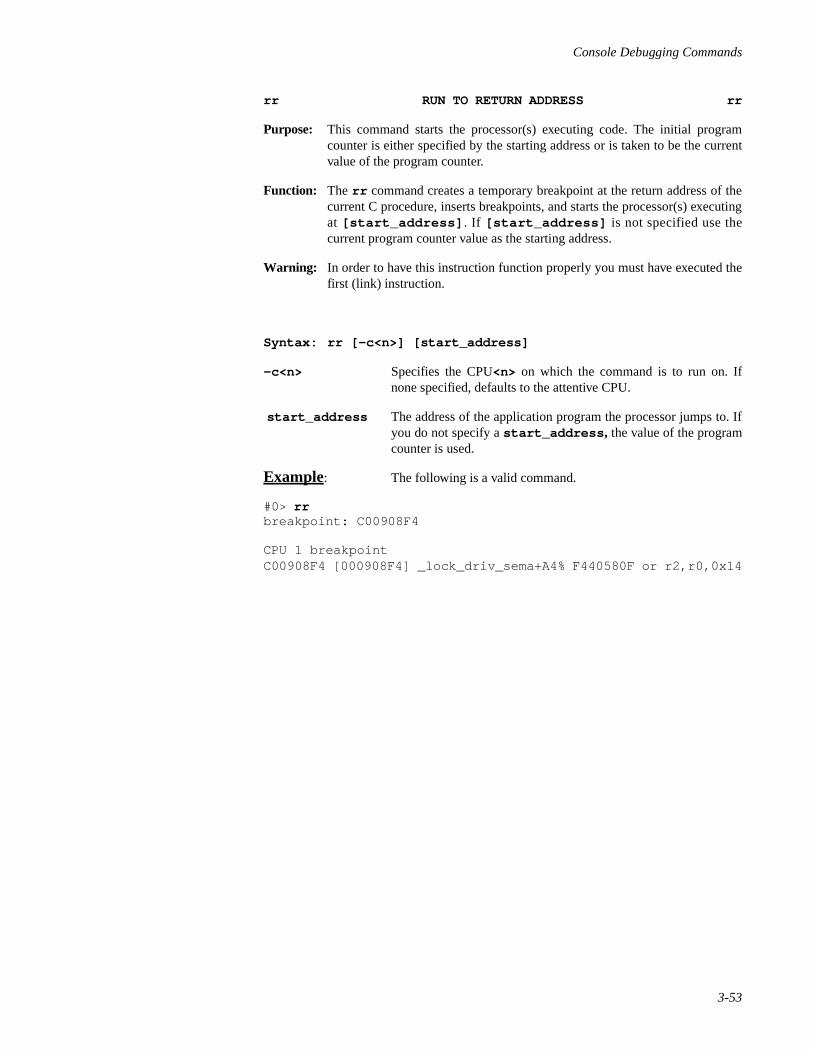
Console Debugging Commands
3-53
rr RUN TO RETURN ADDRESS rr
Purpose: This command starts the processor(s) executing code. The initial programcounter is either specified by the starting address or is taken to be the currentvalue of the program counter.
Function: The rr command creates a temporary breakpoint at the return address of thecurrent C procedure, inserts breakpoints, and starts the processor(s) executingat [start_address] . If [start_address] is not specified use thecurrent program counter value as the starting address.
Warning: In order to have this instruction function properly you must have executed thefirst (link) instruction.
Syntax: rr [-c<n>] [start_address]
-c<n> Specifies the CPU<n> on which the command is to run on. Ifnone specified, defaults to the attentive CPU.
start_address The address of the application program the processor jumps to. Ifyou do not specify a start_address , the value of the programcounter is used.
Example: The following is a valid command.
#0> rrbreakpoint: C00908F4
CPU 1 breakpointC00908F4 [000908F4] _lock_driv_sema+A4% F440580F or r2,r0,0x14

Power Hawk Series 700 Console Reference Manual
3-54
s SEARCH MEMORY FOR DATA s
Purpose: This command displays a range of 256 bytes of memory, NVRAM addressspace or PCI configurat ion space in hexadecimal beginn ing atstart_address. If the search routine locates the requested pattern inthis page, it encloses the pattern with asterisks. Otherwise, it indicates thatthere is no match.
Syntax: s[format] [-b<n>][-p|-n][r]<start_address><pattern>[mask]
format Determines whether the data to be searched is in byte, word, orlongword [b, w, or l ] format (defaults to l if not specified). If youspecify a byte format and have a longword pattern, the routinesearches memory but does not find a match. The byte orderingmodifier r is only effective on w or l data formats, and is ignoredif the -p option is specified.
Note: Note that ‘sr ’ will be interpreted as the ‘sr ’ command, not as the‘s ’ command with an ‘r ’ suffix.
-b<n> Specifies program base address. The base address <n> is addedto all addresses entered from the command line (<n> is zero bydefault).
-p Address arguments are with respect to the PCI configurationspace.
-n Address arguments are with respect to the NVRAM addressspace.
start_address The address at which the search starts.
pattern The pattern for which memory is searched. The pattern can be abyte, word, or longword.
mask The bit mask, which is a hexadecimal value that determines thepart of each longword to be compared with the pattern. Themask can be any hexadecimal value from 00000000 to FFFFFFFF.Default is FFFFFFFF. Bit 1 sets the mask.
Examples: The following are valid commands.
sb0 4 Search for a byte with pattern 4 starting at address 0.
Note: In the following examples, pattern matches arehighlighted in bold type for illustration purposes.
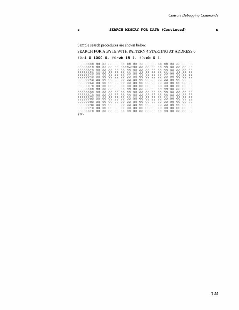
Console Debugging Commands
3-55
s SEARCH MEMORY FOR DATA (Continued) s
Sample search procedures are shown below.
SEARCH FOR A BYTE WITH PATTERN 4 STARTING AT ADDRESS 0
#0> i 0 1000 0. #0>wb 15 4. #0> sb 0 4.
00000000 00 00 00 00 00 00 00 00 00 00 00 00 00 00 00 0000000010 00 00 00 00 00*04*00 00 00 00 00 00 00 00 00 0000000020 00 00 00 00 00 00 00 00 00 00 00 00 00 00 00 0000000030 00 00 00 00 00 00 00 00 00 00 00 00 00 00 00 0000000040 00 00 00 00 00 00 00 00 00 00 00 00 00 00 00 0000000050 00 00 00 00 00 00 00 00 00 00 00 00 00 00 00 0000000060 00 00 00 00 00 00 00 00 00 00 00 00 00 00 00 0000000070 00 00 00 00 00 00 00 00 00 00 00 00 00 00 00 0000000080 00 00 00 00 00 00 00 00 00 00 00 00 00 00 00 0000000090 00 00 00 00 00 00 00 00 00 00 00 00 00 00 00 00000000a0 00 00 00 00 00 00 00 00 00 00 00 00 00 00 00 00000000b0 00 00 00 00 00 00 00 00 00 00 00 00 00 00 00 00000000c0 00 00 00 00 00 00 00 00 00 00 00 00 00 00 00 00000000d0 00 00 00 00 00 00 00 00 00 00 00 00 00 00 00 00000000e0 00 00 00 00 00 00 00 00 00 00 00 00 00 00 00 00000000f0 00 00 00 00 00 00 00 00 00 00 00 00 00 00 00 00#0>

Power Hawk Series 700 Console Reference Manual
3-56
sr SEARCH MEMORY RANGE FOR DATA sr
Purpose: This command searches a range of memory and displays the addresses of allthose locations that contained a matching pattern.
Note: When virtual addressing is used, address translation is performed in ‘data’space.
Syntax: sr[format] [-b<n>]<start_address><end_address><pattern>[mask]
sr[format][-b<n>]<start_address>:<byte_count>pattern> [mask]
format Determines whether the data to be searched is in byte, word, orlongword [b, w, or l ] format. If you specify a byte format andhave a longword pattern, the routine searches memory but doesnot find a match. The byte ordering modifier r is only effective onw or l data formats (defaults to l if not specified), and is ignoredif the -p option is specified.
-b<n> Specifies program base address. The base address <n> is addedto all addresses entered from the command line (<n> is zero bydefault).
start_address The address at which the search starts.
end_address The hexadecimal address at which the operation ends.
:byte_count Number (in hexadecimal) of bytes searched. Note that if youspecify word format, byte_count should be a multiple of two.If you specify longword format , byte_count should be amultiple of four pattern . The pattern for which memory issearched. The pattern can be a byte, word, or longword.
mask The bit mask, which is a hexadecimal value that determines thepart of each longword to be compared with the pattern. The maskcan be any hexadecimal value from 00000000 to FFFFFFFF.Default is FFFFFFFF. Bit 1 sets the mask.
Examples: The following are valid commands.
sr0 1000 70 Search for the pattern 70 at addresses 0 through 1000.
srb0 100 4 Search for a byte with pattern 4 at addresses 0 through 100.
An example search for a byte with a pattern F0 starting at address 0 is shown below.
#0> i 0 1000 0.#0>w 4FC F0.#0>sr0 500 F0.000004FC 000000F0

Console Debugging Commands
3-57
td CONFIGURE CPU DOWN td
Purpose: This command is used on multiprocessor SBCs to mark down the specifiedCPUs. The td command with no arguments may be used to display thecurrent set of ‘up’ and ‘down’ CPUs.
Syntax: td [-s[w]] <cpu list> | all
-s Save latest down state into NVRAM.
-w Save without asking ‘are you sure?’
all Mark all but the master CPU down.
Example: The following is a valid command.
td 1 Disable processor 1.
td -sw 2 Disable processor 2, save list of all disabled processors intoNVRAM and save without asking ‘are you sure?’.

Power Hawk Series 700 Console Reference Manual
3-58
tm CONFIGURE MASTER CPU tm
Purpose: This command changes the CPU the console prefers to run on.
Syntax: tm masterCPU [attentiveCPU]
masterCPU The numeric id of the CPU that is to be the new master CPU.
attentiveCPU The numeric id of the CPU that is to be the new attentive CPU. Ifmissing, the attentive CPU is unchanged.
Example: The following is a valid command.
tm 1 Make CPU 1 the master CPU.
tm 2 3 Make CPU 2 the master CPU and CPU 3 the attentive CPU.

Console Debugging Commands
3-59
tu CONFIGURE CPU UP tu
Purpose: This command is used on multiprocessor SBCs to mark up CPUs. The tucommand with no arguments may be used to display the current set of ‘up’and ‘down’ CPUs.
Syntax: tu [-s[w]] all
tu <CPU list>
-s Save latest down state into NVRAM.
-w Save without asking ‘are you sure?’
all Enables all processors.
Example: The following is a valid command.
tu 1 Enable CPU 1.
tu -sw 2 3 Mark CPU 2 and CPU 3 as ‘up’ and save the complete list of ‘up’ and ‘down’ CPUs into NVRAM.
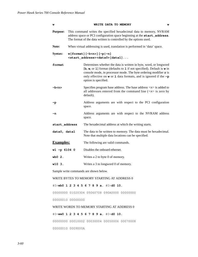
Power Hawk Series 700 Console Reference Manual
3-60
w WRITE DATA TO MEMORY w
Purpose: This command writes the specified hexadecimal data to memory, NVRAMaddress space or PCI configuration space beginning at the start_address .The format of the data written is controlled by the options used.
Note: When virtual addressing is used, translation is performed in ‘data’ space.
Syntax: w[format][-b<n>][-p|-n]<start_address><data0>[data1]...
format Determines whether the data is written in byte, word, or longword[b, w, or l ] format (defaults to l if not specified). Default is w inconsole mode, in processor mode. The byte ordering modifier r isonly effective on w or l data formats, and is ignored if the -poption is specified.
-b<n> Specifies program base address. The base address <n> is added toall addresses entered from the command line (<n> is zero bydefault).
-p Address arguments are with respect to the PCI configurationspace.
-n Address arguments are with respect to the NVRAM addressspace.
start_address The hexadecimal address at which the writing starts.
data0, data1 The data to be written to memory. The data must be hexadecimal.Note that multiple data locations can be specified.
Examples: The following are valid commands.
w1 -p 6104 0 Disables the onboard ethernet.
wb0 2. Writes a 2 to byte 0 of memory.
w10 3. Writes a 3 to longword 0 of memory.
Sample write commands are shown below.
WRITE BYTES TO MEMORY STARTING AT ADDRESS 0
#0>wb0 1 2 3 4 5 6 7 8 9 a. #0>d0 10.
00000000 01020304 05060708 090A0000 00000000
00000010 00000000
WRITE WORDS TO MEMORY STARTING AT ADDRESS 0
#0>ww0 1 2 3 4 5 6 7 8 9 a. #0>d0 10.
00000000 00010002 00030004 00050006 00070008
00000010 0009000A

Console Debugging Commands
3-61
y INITIALIZE y
Purpose: This command initializes all and selects certain processor-specificconfiguration options. The flag bits for the y command are shown inTable 3-6.
Syntax: y flags
flags A numerical value which is the sum of the flag values shown inTable 3-6. below.
Note 1 : The y command always saves its result into NVRAM.
Note 2 : The y command also does a partial soft reset. After its execution,no application state is valid.
Sample initialization commands are shown below.
#0>y0 Initializes system with all caches enabled on all processors.
#0>yb Initializes system and disables data, instruction, and L2 caches on allprocessors.
Table 3-6. y Command Flag Bits
Bit Flag Effect
B0 001 Disable data cache
B1 002 Disable instruction cache
B2 004 Disable branch history table
B3 008 Disable L2 cache
B4 010 Disable L2 copyback/Enable write through
B5 020 Disable use of L2 by instructions
B6 040 Disable use of L2 by data (PPC 7400 only)
B7 080 Disable store gather and speculative reads

Power Hawk Series 700 Console Reference Manual
3-62
z SINGLE–STEP PROCESSOR z
Purpose: This command single–steps a single processor one instruction at a time.Breakpoints are inserted into memory. Any pending interrupts are executedbefore returning control to the console.
Syntax: z [-c<n>][start_address]
-c<n> Single step the specified CPU<n>. If not specified, the attentiveCPU will be stepped.
start_address The address of the instruction to single step. If you omit theaddress , the value of the program counter is used.
Examples: The following are valid commands.
#0>zCPU 0 single stepC0082520 [00082520] _cnrint2ecx+4% 21DF0020 st.d r14,r31,0x20(Note that C0082520 is the next instruction to execute.)
#0>zCPU 0 single stepC0082524 [00082524] _cnrint2ecx+8% 221F0028 st.d r16,r31,0x28
#0>zCPU 0 single stepC0082528 [00082528] _cnrint2ecx+C% 225F0030 st.d r18,r31,0x30
#0>z -c1CPU 1 single step000473dc [0004D3dc] 1cad+4 % 7da80206 mflr r13

Console Debugging Commands
3-63
? HELP COMMAND ?
Purpose: The help command displays a basic list of all the console commands. You canobtain more information about a command by following the question mark (?)with the command letter or another ?. The help command is availableimmediately following power–up. Examples of the help command are shownbelow. The ? command displays help and/or global dash options.
Syntax: ? List of commands.
? a short help overview
?? a much longer help overview
?e help on the ‘e’ command (substitute any other command name for ‘e’)
?- help on th most common command line options
?* help on the most common command line editor
Example: The following are valid commands.
a(scii dump)b(reakpoint)c(opy memory)d(isplay memory in hex)di(sassemble memory) e(xamine/change memory)f(ile operations): fb(oot) fl(oad) fr(un) fc(directory list)etcg(eneral register display/modify) i(nitialize memory to value) k(ick CPUs) m(emory test) o(ptions) p(rocessor register display/modify)q(uery) r(un) s(earch memory)t(configure)w(rite data to memory)y(initialize) z(single step)~b(reboot machine)?(help) ??(more help) ?-(option help) ?*(cmd line editor help)
#0>?a a(scii dump) a[b|w|l][r][-b][-p|-n][start_address [end_address]] a[b|w|l][r][-b][-p|-n][start_address [:byte_count]]

Power Hawk Series 700 Console Reference Manual
3-64
? HELP COMMAND (Continued) ?
#0>???(help)
An expression can be one or more numeric values separated bythe arithmetic operators: plus(+) or minus(-).
numeric value hex digits – hexadecimal number $ – last address value % – contents of program counter %regname – contents of processor register ‘regname – address of processor register [\]symbol – address of symbol BnBn – binary bits ’n’ – ascii value
address value value – address [value] – physical address (value) – virtual address *value:size – indirect address *[value]:size – indirect physical address *(value):size – indirect virtual address
?<cmd> – help on <cmd>?– – help on command options
#0>?- -(local per command options)-p - perform in pci cfg space-n - perform in nvram space -s - store into nvram where appropriate-w - when storing, don't ask `are you sure?'-c<n> - execute on cpu 'n' -r<n> - execute 'n' times (0 = infinite times)
#0>?* *(command line editor keystrokes)^f,^b - move forward/backward one character^a,^e - move to beginning/end of line del,^d - delete one character ^h - delete prev character^n - recall next input line^p - recall previous input line^r,^l - redisplay input line ^k - delete to end of input line^u - delete entire input line

A-1
AAppendix ACommand Summary
111
The following is an alphabetical list of the console commands along with their definitionand syntax.
-A-ASCII Dump
a[b|w|l][r][-b<n>][-p|-n][start_address [end_address]]a[b|w|l][r][-b<n>][-p|-n][start_address [:byte_count]]
–B–
Breakpoints (List)
b
Breakpoints (Set)
b [-a] [-o] <address>
Breakpoints (Clear)
bk <address> | <all>
–C–
Copy Memory
c[b |w | l ] [ r ] [–b<n>] [ -p | -n ]<source_star t_address><source_end_address><destination_start_address>
c [b |w | l ] [ r ] [– b<n>] [ -p | -n ]<source_s ta r t_address> :<by te_ coun t><destination_start_address>
-D-
Display Memory in Hexadecimal
d[b|w|l][r][–b<n>][-p|-n][start_address [end_address]]d[b|w|l][r][–b<n>][-p|-n][start_address [:byte_count]]
Disassemble Memory
di [-b<n>][-p|-n][start_address [end_address]]di [-b<n>][-p|-n][start_address [:byte_count]

Power Hawk Series 700 Console Reference Manual
A-2
–E–
Examine/Change Memory
e[b|w|l][r][–b<n>][-p|-n][start_address[data]]
-F-
Boot Operating System
fb [-c<n>][-q] fB [-c<n>][-q] bootfile
Display Directory
fc [dir_name]
Display/Set the Default Device
fd [dev]
fd [-l]
fd [-s[w]][dev]
Display Mounted File Systems
fh
Load a Program
fl [-c<n>] <filename>
Load and Execute a Program
fr [-c<n>] <filename>[address]
–G–
General Register Display/Modify
g [-c<n>][<register_name>[data]]
–I–
Initialize Memory to Value (Fill)
i[b|w|l][r][-q][-b<n>][-p|-n]<start_address><end_address>[fill_value]i[b|w|l][r][-q][-b<n>][-p|-n]<start_address>:<byte_count>[fill_value]
–K–
Kick CPUsk

Command Summary
A-3
–M–
Memory Test
m[b|w|l][r][-b<n>][-p|-n]<start_address><end_address>m[b|w|l][r][-b<n>][-p|-n]<start_address>:<byte_count>
–O–
Global Command Options
o [+|-][-a][-m][v][-b<n>][-c<n]
–P–
Processor Register Display/Modify
p [-c<n>][<register_name>[data]]p [-s[w]] boot <flags>
–Q–
Query Address
qa <address>
Query Backplane
qb
Query Stack
qs[-c<n>]
Query Virtual Address
qv <virtual address>
Query Boot Options
qy
–R–
Run (Execute)
r [-c<n>][start_address]
Run (Execute to Address)
ra [-c<n>]<address>

Power Hawk Series 700 Console Reference Manual
A-4
Run Without Breakpoints
rd [-c<n>][start_address]
Run to Next Instruction
rn [-c<n>][start_address]
Run to Return Address
rr [-c<n>][start_address]
–S–
Search Memory for Data
s[b|w|l][r][-b<n>][-p|-n][r]<start_address><pattern>[mask]
Search Memory Range for Data
sr[-b|w|l][r][-b<n>][-p|-n]<start_address> <end_address><pattern>[mask]sr[-b|w|l][r][-b<n>][-p|-n]<start_address>:<byte_count><pattern>[mask]
-T-
Configure CPU Down (Multiprocesor SBCs Only)
td <cpu>
Configure Master CPU
tm masterCPU [attentiveCPU]
Configure CPU Up (Multiprocesor SBCs Only)
tu [-s[w]] <cpu>
tu [-s[w]] all
–W–
Write Data to Memory
w[b|w|l][r][-b<n>][-p|-n]<start_address><data0>[data1]
-Y-Initialize
y [-c<n>]flags

Command Summary
A-5
–Z–
Single–Step Processor
z [address][-c<n>]
–?–
Help Command
? a short help overview?? a much long help overview?e help on the ‘e’ command?- help on command line options?* help on the command line editor – help on global options.
The following is a list of the console commands by function.
REGISTER AND MEMORY MANIPULATION
ASCII Dump
a[b|w|][|r][-b<n>][-p|-n][start_address [end_address]]a[b|w|l][r][-b<n>][-p|-n][start_address [:byte_count]]
Copy Memory
c[b |w | l ] [ r ] [–b<n>] [ -p | -n ]<source_star t_address><source_end_address><destination_start_address>c [b |w | l ] [ r ] [– b<n>] [ -p | -n ]<source_s ta r t_address> :<by te_coun t><destination_start_address>
Display Memory in Hexadecimal
d[b|w|l][r][–b<n>][-p|-n][start_address [end_address]]d[b|w|l][r][–b<n>][-p|-n][start_address[:byte_count]]
Disassemble Memory
di [-b<n>][-p|-n][start_address [end_address]]di [-b<n>][-p|-n][start_address [:byte_count]]
Examine/Change Memory
e[b|w|l][r][–b<n>][-p|-n][start_address[data]]
General Register Display/Modify
g [-c<n>][-s[w]][<register_name>[data]]

Power Hawk Series 700 Console Reference Manual
A-6
Initialize Memory to Value (Fill)
i[b|w|l][r][-q][-b<n>][-p|-n]<start_address><end_address>[fill_value]i[b|w|l][r][-q][-b<n>][-p|-n]<start_address>:<byte_count>[fill_value]
Memory Test
m[b|w|l][r][-b<n>][-p|-n]<start_address><end_address>m[b|w|l][r][-b<n>][-p|-n]<start_address>:<byte_count>
Processor Register Display/Modify
p [-c<n>][-s[w]][<register_name>[data]]p [-s[w]] boot <flags>
Search Memory for Data
s[b|w|l][r][-b<n>][-p|-n]<start_address><pattern>[mask]
Search Memory Range for Data
sr[-b|w|l][r][-b<n>][-p|-n]<start_address> <end_address><pattern>[mask]sr[-b|w|l][r][-b<n>][-p|-n]<start_address>:<byte_count><pattern>[mask]
Write Data to Memory
w[b|w|l][r][-b<n>][-p|-n]<start_address><data0>[data1]
FILE OPERATIONS
Boot Operating System
fb [-c<n>][-q]fB [-c<n>][-q] bootfile
Display Directory
fc [dir_name]
Display/Set the Default Device
fd [dev]fd [-l]fd [-s[w]] [dev]

Command Summary
A-7
Display Mounted File Systems
fh
Load a Program
fl [-c<n>]<filename>[address]
Load and Execute a Program
fr [-c<n>]<filename>[address]
EXECUTION
List Breakpoints
b
Set Breakpoints
b [–a] [–o] [–b<n>] <address>
Clear Breakpoints
bk <address> | <all>
Execute Run
r[start_address]
Execute Run To Address
ra <address>
Run Without Breakpoints
rd [start_address]
Run To Next Instruction
rn [start_address]
Run to Return Address
rr [start_address]
Single–Step Processor
z [address]

Power Hawk Series 700 Console Reference Manual
A-8
HELP
Help Command
? a short help overview?? a much long help overview?e help on the ‘e’ command?- help on command line options?* help on the command line editor – help on global options.
MISCELLANEOUS
Global Command Options
o [+|–][-a][-c<n>][m] [r] [v][–b<n>]
Query Address
qa<address>
Query Backplane
qb
Query Stack
qs[-c<n>]
Query Virtual Address
qv<virtual address>
Query Boot Options
qy
Configure CPU Down (Multiprocessor SBCs Only)
td [-s][-w]<CPU list>
Configure CPU Up (Multiprocessor SBCs Only)
tu [-s[w] all
Configure Master CPU (Multiprocessor SBCs Only)
tm masterCPU [attentiveCPU]

Command Summary
A-9
Initialize
y flags
Table A-1 lists the command parameters, range and their definitions.
Table A-1. Command Parameter Definitions
Parameter Range Comment
address Can be any valid physical or virtual address (if the o+voption is set), including the device address.
base The address into which the program is loaded. Default is2000
byte_count Number of bytes displayed.
data [00000000–FFFFFFFF] Data to be passed to the program. This data is formatdependent.
dev mt(c,u,p,b) dsk(c,u,p,b) where c = slot number; u=unit on controller ‘c’; p=partition number (0–7);b=bus number where0 = PCI and 1 = VME
The device that is used by the command.
dir_name The directory name.
destination_start_address
The address where the destination is started
end_address The address at which the operation stops.
fill_value [00000000–FFFFFFFF] The value that is loaded into each memory location.
format [b, w, or l ] [r] The amount of bits that the data appears in. Formats arebyte, word, or longword (b, w, or l ) Default is Big-Endiandisplay; r specifies Little-Endian display.
mask The bit mask is a hexadecimal value that determineswhich part of each longword is to be compared with thepattern.
options -b<n> , -c<n> , -n -p , -o , -s -w
The conditions the console operates under.
pattern [00000000–FFFFFFFF] The pattern for which memory is searched.

Power Hawk Series 700 Console Reference Manual
A-10
register_name pc, msr, cr, spl, r0– r31, lr, ctr, xer, mq, tid, dsisr, dar, fpscr, sr0-sr15, sdr0, sdr1, eim0, eim1, eis0, eis1, 23
The name of a register.
spec A file specification, in the following format: [dev]pathname . This file contains the file to be loaded. If them option of the o command is set (o+m), you mustprovide the device on which the directory is located via afd command or by specifying dsk/ .
start_address The address at which the operation starts.
Table A-1. Command Parameter Definitions (Cont.)
Parameter Range Comment

B-1
BAppendix BError Codes
222
The following is a numerical list of the console error codes that may appear on the screenwhenever a console command is executed and an error is detected.
Debugger Error Codes
error 0001: syntax error
The command entered contained a syntax error. Use the help command to obtain thecorrect syntax (e.g., ?d).
error 0002: undefined symbol
The symbol name used is not defined or the symbols are not loaded. If trying to referencea processor symbol, ensure that the console is in the processor mode (o+p ) and theprocessor symbol table has been loaded. To load processor symbols, bit 7 of the pbootregister must be set (e.g., pboot 80. ) before issuing the fb or fr command.
error 0003: starting address must be less than ending address
When specifying an address range, the second address must be greater than the firstaddress. To specify a byte count instead of an ending address use a colon ‘: ’ (e.g., d100:10 ).
error 0004: illegal CPU number
The processor number used is not a valid processor. Ensure that the processor number is aprocessor and the processor is marked ‘up’. The qb command may be used to query thecurrent configuration.
error 0005: invalid stack frame
The rr command requires that a valid stack frame exists to enable a return address to beextracted. Ensure that the processor has executed the link instruction of the current Cprocedure.
error 0006: date/time format: y/m/d h:m:s
When setting the time of century clock, the format of the date and time was incorrect. Thecorrect format is: y/m/d h:m:s.
error 0007: duplicate breakpoint
An attempt was made to set a breakpoint at an address that already contained a breakpoint.To correct this situation, remove the old breakpoint first with a bk command.

Power Hawk Series 700 Console Reference Manual
B-2
error 0008: breakpoint table full
An attempt was made to set a breakpoint when eight breakpoints already exist. Amaximum of eight breakpoints may be set at any one time. To correct this situationremove an existing breakpoint before setting the new one.
error 0009: memory doesn’t match
While using the e command, data read does not match data written. The e commandalways verifies that it can read any data that it writes.
error 000B: illegal option
An illegal option letter was specified on the o command. A list of legal options may bedisplayed by typing ?o.
error 000C: illegal register
The register name specified after the ‘%’ was not a valid register name. Use the g and pcommand to obtain a complete list of valid register names. If trying to reference aprocessor register, ensure that the console is in the processor mode (o+p).
error 000D: no symbol for address
An address was specified on a command that did not correspond to a symbol name. Ensurethat the correct mode processor (o+p ) or CP (o–p ) is set. Also ensure that the symboltable is loaded. To load processor symbols, bit 7 of the pboot register must be set (e.g.,pboot 80 .) before issuing the fb or fr command.
error 000F: illegal option ’–n’
An illegal option n was used on a command. Use the help command to obtain a list oflegal options for the command.
error 0010: option ’–n’ requires an argument
The option n requires an argument. Ensure that there is no space between the option letterand the argument (e.g., –c3 is correct, –c 3 is wrong). Use the help command to get alist of legal options for the command.
error 0011: console locked
An attempt was made to use the console when it was disabled at the control panel switch.Before using the console, it must be enabled at the control panel switch.
error 0012: unable to access memory using backplane
The console is unable to access system memory using the backplane. Most likely systemmemory is not functional. Use the m command to verify system memory.
error 0013: failed to load/boot
The fb command was unable to load the program “boot” from the default boot device.Ensure that the correct boot device is selected with the fd command.

Error Codes
B-3
error 0014: low tocc battery
When accessing the time of century clock (TOCC), the console detected a low battery. Tocorrect this problem, replace the TOCC battery.
error 001B: bad device or pathname
An invalid device name or pathname was specified on one of the f commands. Ensure thatthe pathname starts with a slash / . Use the help command ?f to verify the correct syntaxis being used. The device must be either dsk(c,u,p,b) or mt(c,u,p,b) (e.g., fddsk(0), fd mt(0) .
Where: c – controller numberu – unit number (optional)p – partition number (optional)b – bus number (optional) (0=primary).
error 0020: read failed, offset x
A disk or tape read at byte offset x failed. To correct this problem, try a different disk ortape drive.
error 0021: open failed
The open of a disk or tape failed.
error 0022: n in open
An illegal bus was specified on a f command. Use a 0 to specify the primary bus, and a 1for the secondary bus. Ensure that the bus exists. Use the qb command to query thesystem configuration.
error 0022: n in open
A device type other than ‘dsk’ or ‘mt’ was used.
error 0023: not a directory
Either an I/O error occurred or the device does not contain a valid file system. Verify thatthe disk or tape contains valid data and retry the command.
error 0027: CPU x failed to single step
The console single steps a processor by setting the trace bit in the sr register and runningthat particular processor. If the processor does not take a trace exception within onesecond, the single step fails. This error most frequently occurs with the z command, but itcan also occur with the r command. The r command uses single stepping to skip overbreakpoints.
error 0029: a: expected n, actual m
A memory test detected an error at address a. The value n was written to memory and thevalue m was read back.

Power Hawk Series 700 Console Reference Manual
B-4
error 002A: All CPUs must be halted
An f command was attempted when one or more processors where running. All of theprocessors must be halted with the h command before initiating an f command.
error 002E: invalid memory destination
An internal error occurred in the console which caused it to perform an invalid memoryreference. Reset the console with <CR>~b and retry the command.
error 002F: register ’n’ is read only
An attempt was made to modify processor register n. Register n is a read only register andmay not be modified.
error 0030: CPU must be running
A command was attempted that expected a running processor. If a tu command (applica-ble to multiprocessor SBCs only) was being attempted use the r command instead.
Console Debugger Error Codes
error 0201: boot script missing
A script by the name ‘boot’ should always exist. The ‘boot’ script gets executed at powerup and should contain commands to boot the operating system. The default ‘boot’ scriptcontains the command fb .
error 0202: slot n is not valid
A command referenced slot n that was either empty or did not contain a board of theproper type. Use the qb command to display the hardware configuration of the system.
error 020F: invalid segment descriptor, vaddr=n
While translating virtual address n to a physical address, the console referenced an invalidsegment descriptor in system memory. Ensure that the crp and segment descriptor arevalid.
error 0210: page not in memory, vaddr=n
While translating virtual address n to a physical address, the console detected that the pagecontaining the virtual address was not in system memory. Since the page is not in memorythe data in this page is not accessible to the console. Ensure that the virtual address iswithin the bounds of the memory allocated to be accessed by the console.
error 0264: CPU n marked down
For multiprocessor SBCs only. Processor n was marked down due to either a td commandor the detection of an error. The up/down status of a processor can be checked via the qbcommand.
error 0265: CPU n is not valid
A command referenced a processor that does not exist. Use the qb command to displaythe system hardware configuration.
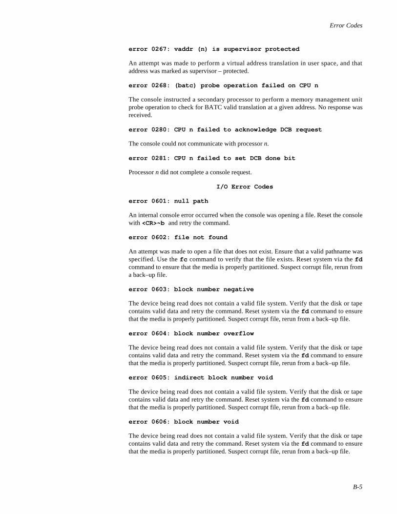
Error Codes
B-5
error 0267: vaddr (n) is supervisor protected
An attempt was made to perform a virtual address translation in user space, and thataddress was marked as supervisor – protected.
error 0268: (batc) probe operation failed on CPU n
The console instructed a secondary processor to perform a memory management unitprobe operation to check for BATC valid translation at a given address. No response wasreceived.
error 0280: CPU n failed to acknowledge DCB request
The console could not communicate with processor n.
error 0281: CPU n failed to set DCB done bit
Processor n did not complete a console request.
I/O Error Codes
error 0601: null path
An internal console error occurred when the console was opening a file. Reset the consolewith <CR>~b and retry the command.
error 0602: file not found
An attempt was made to open a file that does not exist. Ensure that a valid pathname wasspecified. Use the fc command to verify that the file exists. Reset system via the fdcommand to ensure that the media is properly partitioned. Suspect corrupt file, rerun froma back–up file.
error 0603: block number negative
The device being read does not contain a valid file system. Verify that the disk or tapecontains valid data and retry the command. Reset system via the fd command to ensurethat the media is properly partitioned. Suspect corrupt file, rerun from a back–up file.
error 0604: block number overflow
The device being read does not contain a valid file system. Verify that the disk or tapecontains valid data and retry the command. Reset system via the fd command to ensurethat the media is properly partitioned. Suspect corrupt file, rerun from a back–up file.
error 0605: indirect block number void
The device being read does not contain a valid file system. Verify that the disk or tapecontains valid data and retry the command. Reset system via the fd command to ensurethat the media is properly partitioned. Suspect corrupt file, rerun from a back–up file.
error 0606: block number void
The device being read does not contain a valid file system. Verify that the disk or tapecontains valid data and retry the command. Reset system via the fd command to ensurethat the media is properly partitioned. Suspect corrupt file, rerun from a back–up file.

Power Hawk Series 700 Console Reference Manual
B-6
error 0607: not a directory
The device being read does not contain a valid file system. Verify that the disk or tapecontains valid data and retry the command. Reset system via the fd command to ensurethat the media is properly partitioned. Suspect corrupt file, rerun from a back–up file.
error 0608: zero length directory
The device being read does not contain a valid file system. Verify that the disk or tapecontains valid data and retry the command. Reset system via the fd command to ensurethat the media is properly partitioned. Suspect corrupt file, rerun from a back–up file.
error 060E: cannot write files
An attempt was made to write a file. The console does not support device writes. Thiserror code should not occur under normal operating conditions and therefore it indicatesan operator error. Reset the console with <CR>~b and retry the command.
error 060F: no more file slots
An internal console error occurred while opening a file. Reset the console with <CR>~band retry the command. If error still occurs, suspect a corrupted file.
error 0610: no more disk buffers
An internal console error occurred while allocating a disk buffer. This error code shouldnot occur under normal operating conditions and therefore it indicates an operator error.Reset the console with <CR>~b and retry the command.
error 0611: super block read error
The device being read does not contain a valid file system. Verify that the disk or tapecontains valid data and retry the command. Reset system via the fd command to ensurethat the media is properly partitioned. Suspect corrupt file, rerun from a back–up file.
error 0612: read error
An I/O read error occurred. Previous message should indicate type of error.
error 0613: zero length directory record
The device being read does not contain a valid file system. Verify that the disk or tapecontains valid data and retry the command. Reset system via the fd command to ensurethat the media is properly partitioned. Suspect corrupt file, rerun from a back–up file.
error 0614: bad magic number in super block
The device being read does not contain a valid file system. Verify that the disk or tapecontains valid data and retry the command. Reset system via the fd command to ensurethat the media is properly partitioned. Suspect corrupt file, rerun from a back–up file.
error 0615: CP system device unavailable, retrying
The console was unable to open the boot device during a fb command. The consoleattempts 12 retries then stops trying. Ensure that at least one Generic Disk (GD) diskcontroller exists in the primary I/O bus and the disk is spun up and ready.

Error Codes
B-7
640 Series Console Errors
These error codes (0640 through 064F) apply to the Concurrent SCSI Adapters, GenericDisk (GD), and Generic Tape (GT) devices, and the definition of the symptom will reflectwhich controller is displaying the error code. For example, if error 0645: NCRController not found is displayed on the console terminal, then the NCR controlleris the source of the error code. However, if the generic disk controller is indicating thissame error: error 0645: GD:Controller not found is displayed on the consoleterminal.
error 0640: ___: No error
This error can only result from an internal hardware or software error.
error 0641: ___: Interface not configured
This error results from selecting a disk or tape device that is not valid for this machinetype. Use the fd command to select an appropriate device type.
error 0642: ___: Invalid Command
This error can only result from an internal hardware or software error.
error 0643: ___: Unsupported command
This error can only result from an internal hardware or software error.
error 0644: ___: Bad device specification
This error results from selecting a disk or tape device that is not valid. Use the fdcommand to select an appropriate device type.
error 0645: ___: Controller not found
This error results when an invalid controller number has been provided as part of a devicespecification. Use the fd command to select an appropriate controller number (0 through9).
error 0646: ___: Device not found
This error results when the device was not found at the specified hardware address. Usethe fd command to select a new device address.
error 0647: ___: Device type mismatch
This error results when the device specification referred to a disk (tape) when the realdevice found at that address was a tape (disk). Ensure that the correct address was usedwith the fd command.
error 0648: ___: Controller timed out
This error results when a I/O controller (NCR or IS) or device malfunctions, or an internalsoftware error occurs. Suspect the I/O controller or device malfunction. Reset the systemand retry the command.
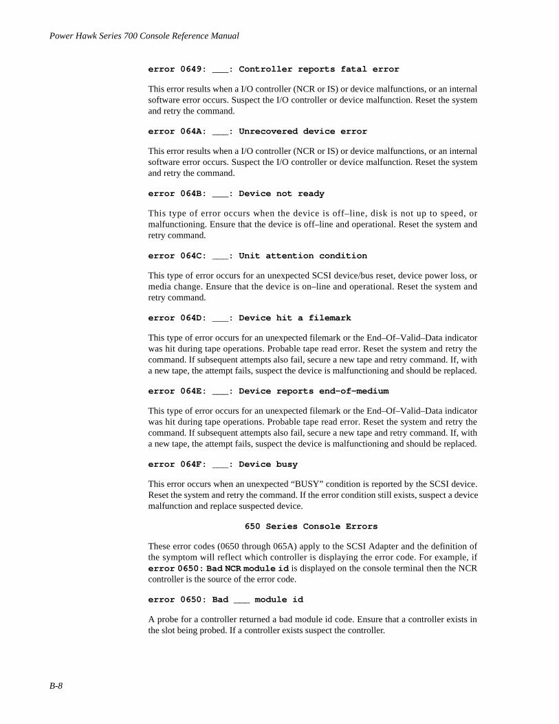
Power Hawk Series 700 Console Reference Manual
B-8
error 0649: ___: Controller reports fatal error
This error results when a I/O controller (NCR or IS) or device malfunctions, or an internalsoftware error occurs. Suspect the I/O controller or device malfunction. Reset the systemand retry the command.
error 064A: ___: Unrecovered device error
This error results when a I/O controller (NCR or IS) or device malfunctions, or an internalsoftware error occurs. Suspect the I/O controller or device malfunction. Reset the systemand retry the command.
error 064B: ___: Device not ready
This type of error occurs when the device is off–line, disk is not up to speed, ormalfunctioning. Ensure that the device is off–line and operational. Reset the system andretry command.
error 064C: ___: Unit attention condition
This type of error occurs for an unexpected SCSI device/bus reset, device power loss, ormedia change. Ensure that the device is on–line and operational. Reset the system andretry command.
error 064D: ___: Device hit a filemark
This type of error occurs for an unexpected filemark or the End–Of–Valid–Data indicatorwas hit during tape operations. Probable tape read error. Reset the system and retry thecommand. If subsequent attempts also fail, secure a new tape and retry command. If, witha new tape, the attempt fails, suspect the device is malfunctioning and should be replaced.
error 064E: ___: Device reports end–of–medium
This type of error occurs for an unexpected filemark or the End–Of–Valid–Data indicatorwas hit during tape operations. Probable tape read error. Reset the system and retry thecommand. If subsequent attempts also fail, secure a new tape and retry command. If, witha new tape, the attempt fails, suspect the device is malfunctioning and should be replaced.
error 064F: ___: Device busy
This error occurs when an unexpected “BUSY” condition is reported by the SCSI device.Reset the system and retry the command. If the error condition still exists, suspect a devicemalfunction and replace suspected device.
650 Series Console Errors
These error codes (0650 through 065A) apply to the SCSI Adapter and the definition ofthe symptom will reflect which controller is displaying the error code. For example, iferror 0650: Bad NCR module id is displayed on the console terminal then the NCRcontroller is the source of the error code.
error 0650: Bad ___ module id
A probe for a controller returned a bad module id code. Ensure that a controller exists inthe slot being probed. If a controller exists suspect the controller.

Error Codes
B-9
error 0651: Bad ___ bus no
An open of a device was attempted with a bad bus number. Ensure that a valid bus number(0 = primary) is specified on the fd command.
error 0652: Bad ___ slot no
An open of a device was attempted with a bad slot number. Ensure that a valid slot number(2 through 9) is specified on the fd command.
error 0653: Bad ___ ctrl no
An open of a device was attempted with a bad controller number. Ensure that a validcontroller number (2 through 9) is specified on the fd command.
error 0654: Bad ___ unit no
An open of a device was attempted with a bad drive number. Ensure that a valid unitnumber (0 through 7) is specified on the fd command.
error 0655: Bad ___ partition no
An open of a device was attempted with a bad partition number. Ensure that a validpartition number (0 through 7) is specified on the fd command.
error 0657: ___: SCSI request sense failed
This type of error occurs when a NCR or SCSI device is malfunctioning. Reset the systemand retry the command. If the error still occurs, suspect a device or controller malfunction.Attempt to run the I/O diagnostic programs.
error 0658: ___: SCSI inquiry failed
This type of error occurs when a NCR or SCSI device is malfunctioning. Reset the systemand retry the command. If the error still occurs, suspect a device or controller malfunction.Attempt to run the I/O diagnostic programs.
error 0659: ___: SCSI test unit ready failed
This type of error occurs when a NCR or SCSI device is malfunctioning. Reset the systemand retry the command. If the error still occurs, suspect a device or controller malfunction.Attempt to run the I/O diagnostic programs.
error 065A: ___: SCSI load tape command failed
This type of error occurs when a NCR or SCSI device is malfunctioning. Reset the systemand retry the command. If the error still occurs, suspect a device or controller malfunction.Attempt to run the I/O diagnostic programs.
6B0 Series Console Errors
These error codes (06B0 through 06B4) apply to the Generic Disk (GD) and Generic Tape(GT) devices, and the definition of the symptom will reflect which controller is displayingthe error code. For example, if error 06B0:GT:Interface not found is displayed onthe console terminal, the generic tape controller is the source of the error code. However,if the generic disk controller is indicating this same error: error 06B0: GD: Inter-face not found is displayed on the console terminal.

Power Hawk Series 700 Console Reference Manual
B-10
error 06B0: ___: Interface not found
This error can only result from an internal hardware or software error.
error 06B1: ___: Device not initialized
This error can only result from an internal hardware or software error.
error 06B2: ___: Read failed
This error results when a I/O controller or device malfunctions, or an internal softwareerror occurs. Suspect the I/O controller or device malfunction. Reset the system and retrythe command. If the operation still fails, ensure that the I/O controller and device are allthe current revision and run the diagnostic programs to validate the hardware.
error 06B3: ___: Write unsupported
This error can only result from an internal hardware or software error.
error 06B4: ___: Bad request size
This error can only result from an internal hardware or software error.
error 06C0: GD: Can’t read disk status
This error results when a I/O controller or device malfunctions, or an internal softwareerror occurs. Suspect the I/O controller or device malfunction. Reset the system and retrythe command. If the operation still fails, ensure that the I/O controller or device are all thecurrent revision and run the diagnostic programs to validate the hardware.
error 06C2: GD: Drive off-line
An I/O request to the GD controller returned drive off–line status. Ensure that the drive ison–line and retry the command.
error 06C3: GD: Can’t read geometry block
Either an I/O error occurred or the disk has not been formatted. Verify that the disk hasbeen properly formatted. Suspect a medium fault. Restore file and reformat.
error 06C4: GD: Bad geometry block header
Either an I/O error occurred or the disk has not been formatted. Verify that the disk hasbeen properly formatted. Suspect a medium fault. Restore file and reformat.
error 06C5: GD: Bad geometry block checksum
Either an I/O error occurred or the disk has not been formatted. Verify that the disk hasbeen properly formatted. Suspect a medium fault. Restore file and reformat.
error 06C6: GD: Null partition
A null length partition was specified on the fd command. To correct this situation, selecta different partition with the fd dsk(n,n,partition no.) command and retry thecommand. Suspect media.

Error Codes
B-11
error 06D0: GT: Seek failed
This type of error occurs when a SCSI device is malfunctioning. Reset the system andretry the command. If the error still occurs, suspect a device malfunction. Attempt to runthe I/O diagnostic programs and replace board(s) indicated.
error 06D1: GT: Load command failed
This type of error occurs when a SCSI device is malfunctioning. Reset the system andretry the command. If the error still occurs, suspect a device malfunction. Attempt to runthe I/O diagnostic programs and replace board(s) indicated.
error 06D2: GT: Unload command failed
This type of error occurs when a SCSI device is malfunctioning. Reset the system andretry the command. If the error still occurs, suspect a device malfunction. Attempt to runthe I/O diagnostic programs and replace board(s) indicated.
error 06D3: GT: Rewind command failed
This type of error occurs when a SCSI device is malfunctioning. Reset the system andretry the command. If the error still occurs, suspect a device malfunction. Attempt to runthe I/O diagnostic programs and replace board(s) indicated.
error 06D4: GT: Space fwd file command failed
This type of error occurs when a SCSI device is malfunctioning. Reset the system andretry the command. If the error still occurs, suspect a device malfunction. Attempt to runthe I/O diagnostic programs and replace board(s) indicated.
error 06D5: GT: Space back rec command failed
This type of error occurs when a SCSI device is malfunctioning. Reset the system andretry the command. If the error still occurs, suspect a device malfunction. Attempt to runthe I/O diagnostic programs and replace board(s) indicated.
error 06D6: GT: Space fwd rec command failed
This type of error occurs when a SCSI device is malfunctioning. Reset the system andretry the command. If the error still occurs, suspect a device malfunction. Attempt to runthe I/O diagnostic programs and replace board(s) indicated.
error 06D7: GT: Cannot seek to partition
This type of error occurs for an unexpected filemark or the End–Of–Valid–Data indicatorwas hit during tape operations. Probable tape read error. Reset the system and retry thecommand. If subsequent attempts also fail, secure a new tape and retry command. If, witha new tape, the attempt fails, suspect the device is malfunctioning and should be replaced.
error 0972: CPU n failed interrupt reset: RHAC = X
Processor n could not reset all interrupt requests.
error 0973: CPU n IGA configuration ram xxx: expected xxreceived xx
Processor n interrupt configuration RAM failed test.

Power Hawk Series 700 Console Reference Manual
B-12
error 0974: CPU n IGA level decode programming failed
Processor n failed the level decode programming.
error 0975: CPU n IGA ipl decode programming failed
Processor n failed the ipl decode programming.
error 0976: CPU n IGA vector table programming failed
Processor n failed the vector table programming.
error 0980: CPU n exception: vector x (”description”) epsr x exip xenip x
Processor n had an unexpected exception, a register dump follows to aid in debugging
error 0981: CPU n cannot be disabled
Processor n can not be disabled via normal procedures.
error 0983: Cannot single–step across a trap/rte instruction, pc = x
A trap or rte instruction at pc location x cannot be single-stepped.
0984: exception x occurred while processing exception y
Another exception x occurred during the processing of exception y.
error 0990: board in slot n failed to report board configuration
The processor board in slot n did not power up/reset correctly.
error 0991: CPU n failed to report status after reset
Processor n did not report its error status after a reset.
error 0992: CPU n reported error code x (description)
Processor n reported error x which is described here.
error 0993: Global memory x failed RAM test
The global memory x failed RAM test during reset, and is currently not being used by theconsole.
error 0999: Backplane reset aborted
An error condition was detected which caused the reset of the backplane to be aborted.
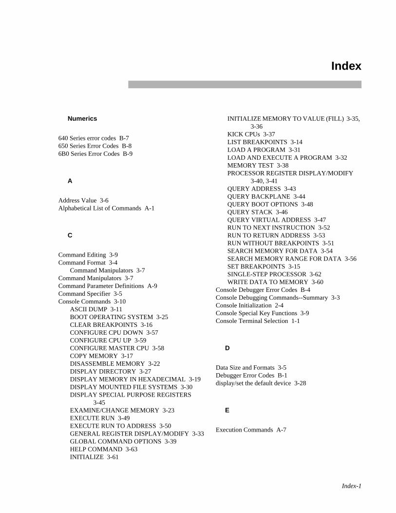
Index-1
Numerics
640 Series error codes B-7650 Series Error Codes B-86B0 Series Error Codes B-9
A
Address Value 3-6Alphabetical List of Commands A-1
C
Command Editing 3-9Command Format 3-4
Command Manipulators 3-7Command Manipulators 3-7Command Parameter Definitions A-9Command Specifier 3-5Console Commands 3-10
ASCII DUMP 3-11BOOT OPERATING SYSTEM 3-25CLEAR BREAKPOINTS 3-16CONFIGURE CPU DOWN 3-57CONFIGURE CPU UP 3-59CONFIGURE MASTER CPU 3-58COPY MEMORY 3-17DISASSEMBLE MEMORY 3-22DISPLAY DIRECTORY 3-27DISPLAY MEMORY IN HEXADECIMAL 3-19DISPLAY MOUNTED FILE SYSTEMS 3-30DISPLAY SPECIAL PURPOSE REGISTERS
3-45EXAMINE/CHANGE MEMORY 3-23EXECUTE RUN 3-49EXECUTE RUN TO ADDRESS 3-50GENERAL REGISTER DISPLAY/MODIFY 3-33GLOBAL COMMAND OPTIONS 3-39HELP COMMAND 3-63INITIALIZE 3-61
INITIALIZE MEMORY TO VALUE (FILL) 3-35, 3-36
KICK CPUs 3-37LIST BREAKPOINTS 3-14LOAD A PROGRAM 3-31LOAD AND EXECUTE A PROGRAM 3-32MEMORY TEST 3-38PROCESSOR REGISTER DISPLAY/MODIFY
3-40, 3-41QUERY ADDRESS 3-43QUERY BACKPLANE 3-44QUERY BOOT OPTIONS 3-48QUERY STACK 3-46QUERY VIRTUAL ADDRESS 3-47RUN TO NEXT INSTRUCTION 3-52RUN TO RETURN ADDRESS 3-53RUN WITHOUT BREAKPOINTS 3-51SEARCH MEMORY FOR DATA 3-54SEARCH MEMORY RANGE FOR DATA 3-56SET BREAKPOINTS 3-15SINGLE-STEP PROCESSOR 3-62WRITE DATA TO MEMORY 3-60
Console Debugger Error Codes B-4Console Debugging Commands--Summary 3-3Console Initialization 2-4Console Special Key Functions 3-9Console Terminal Selection 1-1
D
Data Size and Formats 3-5Debugger Error Codes B-1display/set the default device 3-28
E
Execution Commands A-7
Index

Power Hawk Series 700 Console Reference Manual
Index-2
F
FDiag Initialization 2-1File Operations Commands A-6
G
Global Options 3-5
H
Help Command A-8
I
I/O Error Codes B-5
L
Local Options 3-6
M
Miscellaneous Commands A-8
N
Numeric Values 3-6
P
PPCBUG routine 1-1program counter 3-49
R
Register and Memory Minipulation Commands A-5
S
SMON Initialization 2-2Summary of Commands 3-1
Command Editing 3-9Syntax Conventions 3-2System Boot 2-5System Entry to Console 2-7System Initialization 2-1
V
VGM5 Reset Switch 2-8VGM5 SMI Switch 2-8VSS4 Reset Switch 2-9VSS4 SMI Switch 2-9


Spine for 1/2” Binder
Product Name: 0.5" fromtop of spine, Helvetica,36 pt, Bold
Volume Number (if any):Helvetica, 24 pt, Bold
Volume Name (if any):Helvetica, 18 pt, Bold
Manual Title(s):Helvetica, 10 pt, Bold,centered vertically within space above bar,double space betweeneach title
Bar: 1" x 1/8" beginning1/4" in from either side
Part Number: Helvetica,6 pt, centered, 1/8" up
Power Hawk
Series 700Console Ref Man
0830059
Hardware
Pow
er Haw
k S
eries 700 System
s


![æ ò Y - WKO.at9714]-NEKP... · ï d ] o í x x x x x x x x x x x x x x x x x x x x x x x x x x x x x x x x x x x x x x x x x x x x x x x x x x x x x x x x x x x x x x x x x x x](https://img.dokumen.tips/doc/110x75/5fbaf04dd150160874293c04/-y-wkoat-9714-nekp-d-o-x-x-x-x-x-x-x-x-x-x-x-x-x-x-x-x-x-x.jpg)


![ဦ · u v v / v ] w zd ' e z > x x x x x x x x x x x x x x x x x x x x x x x x x x x x x x x x x x x x x x x x x x x x x x x x x x x x x x x x x x x x x x x x x x x x x x x](https://img.dokumen.tips/doc/110x75/5e436548d273ae1ad25e8202/-u-v-v-v-w-zd-e-z-x-x-x-x-x-x-x-x-x-x-x-x-x-x-x-x-x-x-x-x-x-x-x-x-x.jpg)


