Embed Size (px)
Citation preview

CALEDONIAN COLLEGE OF
ENGINEERING, OMAN
Power Engineering Laboratory Hand-Book
DEPARTMENT OF ELECTRONIC & COMPUTER ENGINEERING CALEDONIAN COLLEGE OF ENGINEERING
Power Engineering Laboratory Hand-Book
Dept of Electronic & Computer Engineering 1
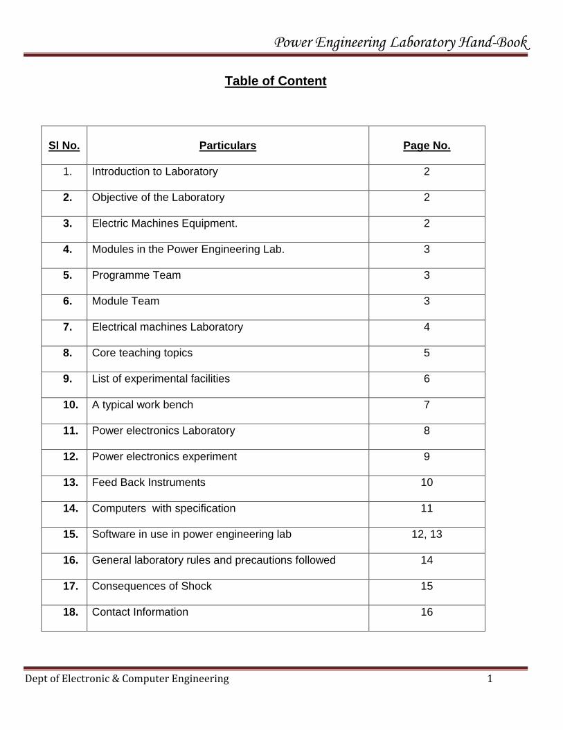
Table of Content
Sl No.
Particulars
Page No.
1. Introduction to Laboratory
2
2. Objective of the Laboratory
2
3. Electric Machines Equipment.
2
4. Modules in the Power Engineering Lab.
3
5. Programme Team
3
6. Module Team
3
7. Electrical machines Laboratory
4
8. Core teaching topics
5
9. List of experimental facilities
6
10. A typical work bench
7
11. Power electronics Laboratory
8
12. Power electronics experiment
9
13. Feed Back Instruments
10
14. Computers with specification
11
15. Software in use in power engineering lab
12, 13
16. General laboratory rules and precautions followed
14
17. Consequences of Shock
15
18. Contact Information
16

Power Engineering Laboratory Hand-Book
Dept of Electronic & Computer Engineering 2
Introduction to Laboratory
Power Engineering Lab comes within the umbrella of Electrical Power Engineering Programme of
Electronic and Computer Engineering Dept. Students of Electrical Power Engineering and Mechatronics
Engineering Programmes utilize the Lab for their hands-on experience. Students of level 2, 3 and 4 frequent
this Lab regularly for their course work requirements.
Power Engineering Lab can be broadly segregated into:
1) Electrical Machines Lab.
2) Power Electronics Lab
The Electric Machines Laboratory is currently located in Room L-5 and it supports hardware
experimental set-ups and multipurpose software that cater for Electrical Engineering, Power Electronics and
General Engineering.
Objective of the Laboratory
The objective of the laboratory is to provide the students with an opportunity to put theory into practice. It
also encourages the students to troubleshoot the system in organized and established manner. This lab
gives the students the first hand chance to get familiar with basic machines which will be useful in Electrical
systems, Power electronics, power systems and of course doing course work and Projects in different areas
of Electrical Engineering. Besides, the lab instills in the students the awareness and practice of safety.

Power Engineering Laboratory Hand-Book
Dept of Electronic & Computer Engineering 3
Modules in the Power Engineering Lab.
Sl No
MODULE NAME
LEVEL
1 Electrical Systems
2
2 Plant and Electrical Distribution Systems
3
3 Power Electronic System – 3
3
4 Power plant – Commissioning Maintenance and Reliability
3
5 Control Engineering -4
4
6 Power System Technology
4
7 High Voltage Plant & Condition Monitoring
4
8 Electrical Machines
4
Course work, Project Work
Programme Team
Sl No.
Name of Faculty
Designation
Office
Extn
1
Mr Parmal Singh Solanki
Senior Lecturer
R 205
404
2
Mr Dharmasa
Senior Lecturer
R 203
421
3
Ms Asma Irfan Shaikh
Lecturer
R 203
407
4
Ms Sumitha Premachandran
Lecturer
PC 043
428
5
Ms. Asiya Najeeb
Assistant Lecturer
R 203
409

Power Engineering Laboratory Hand-Book
Dept of Electronic & Computer Engineering 4
Electric Machines Laboratory
Electric Machines Lab Equipment.
Electrical machines lab comprises of modular electric machines training equipment. There are many kits
such as single and three phase transformers, various dc machines, ac machines single and three phase
induction machines and synchronous machines.
Additional hardware includes power supplies with variable and fixed ac/dc, resistive, inductive loads,
rheostats, changeover switches, dynamometer loading for motors and measurement meters such as digital
ammeters, wattmeter’s, voltmeters, tachometers etc.
The Experimental Panel consists of Protection devices such as fuse, MCB, Auto transformer or Three
point starter for starting the machine or increasing the voltage, different meters such as Voltmeter, Ammeter,
Watt meter for measuring the readings and different rheostat for controlling the different parameters and
different loads for applying the load.
One kit from Feedback Instruments is embedded with virtual instrumentation. The other kits are supplied
by National Instruments Bangalore.
One cut section model is available of machines. The lab undergoes continuous improvement.

Power Engineering Laboratory Hand-Book
Dept of Electronic & Computer Engineering 5
CORE TEACHING TOPICS (MACHINES LAB)
LOAD TEST ON 3 HP, 3-PHASE SLIP-RING INDUCTION MOTOR
LOAD TEST ON 3 HP, 3-PHASE SQUIRREL CAGE INDUCTION MOTOR
PARALLEL OPERATION OF 1 / 2 KVA, 3 PHASE TRANSFORMER
LOAD TEST ON 1 / 2 KVA, 1-PHASE TRANSFORMER.
LOAD TEST ON DC COMPOUND GENERATOR
LOAD TEST ON DC SERIES MOTOR
PARALLEL OPERATION OF 3 KVA, 3-PHASE ALTERNATOR.
SPEED CONTROL OF DC SHUNT MOTOR.
LOAD TEST ON SINGLE PHASE CAPACITOR START INDUCTION MOTOR
SYNCHRONISATION OF 3-PHASE ALTERNATORS
CHARACTERISTICS OF A DC SHUNT GENERATOR.
LOAD TEST ON SYNCHRONOUS MOTOR.
OPEN CIRCUIT & SHORT CIRCUIT OF TRANSFORMER

Power Engineering Laboratory Hand-Book
Dept of Electronic & Computer Engineering 6
LIST OF EXPERIMENTAL FACILITIES
(MACHINES LAB)
3 HP 3 PHASE SLIP-RING INDUCTION MOTOR COUPLED TO DC SHUNT GENERATOR
3 HP 3 PHASE SQUIRREL CAGE INDUCTION MOTOR
1 / 2 KVA, 3 PHASE TRANSFORMER TEST RIG
1 / 2 KVA, TRANSFORMER TEST RIG
DC COMPOUND MOTOR COUPLED TO DC COMPOUND GENERATOR
DC SERIES MOTOR COUPLED TO SERIES GENERATOR
DC SHUNT MOTOR COUPLED TO 3 KVA 3 PHASE ALTERNATOR
DC SHUNT MOTOR COUPLED TO DC SHUNT GENERATOR TEST RIG
SINGLE PHASE CAPACITOR START INDUCTION MOTOR
1 / 2 KVA TRANSFORMER TEST RIG
SYNCHRONISATION OF ALTERNATORS
PARALLEL OPERATION OF TRANSFORMERS.

Power Engineering Laboratory Hand-Book
Dept of Electronic & Computer Engineering 7
Typical work bench

Power Engineering Laboratory Hand-Book
Dept of Electronic & Computer Engineering 8
POWER ELECTRONICS LABORATORY
Power Electronics Lab consists of both Software and Hardware experiments.
Hardware Experiments are done on Readymade kits available. Kit is having the circuits built in
inside the module and the circuit diagram drawn outside the module. Students have to wire up
the circuit as per the circuit diagram.
Experiments are based on IGBT, DIAC, TRIAC, MOSFET, SCR etc.
External devices such as power supply, rheostat, triggering circuit etc are given.

Power Engineering Laboratory Hand-Book
Dept of Electronic & Computer Engineering 9
POWER ELECTRONICS EXPERIMENTS
MOSFET- STEP UP AND STEP DOWNCHOPPER- 30 V/2A
SINGLE PHASE MCMURRAY BRIDGE INVERTOR POWER CIRCUIT
SCR DC CHOPPER POWER CIRCUIT
DC CHOPPER FIRING CIRCUIT
1 PH BRIDGE INVERTOR FIRING CIRCUIT
SINGLE PHASE CYCLO CONVERTOR POWER CIRCUIT
PARALLEL BRIDGE INVERTER POWER CIRCUIT - PBI
SINGLE PHASE CONVERTOR POWER CIRCUIT- 230 V / 5 AMP
3 PHASE IGBT BASED PWM INVERTOR – 0.5 HP/ 230 V
SINGLE PHASE PWM INVERTOR – IGBT BASED
FOUR QUADRANT CHOPPER- IGBT BASED
SERIES INVERTOR
PARALLEL INVERTOR
SINGLE PHASE CYCLO CONVERTOR FIRING UNIT
SINGLE PHASE CONVERTOR – FIRING CIRCUIT

Power Engineering Laboratory Hand-Book
Dept of Electronic & Computer Engineering 10
Feed Back Instruments
SL NO. DESCRIPTION
1. Universal Power Supply
2. Single Phase Transformer
3. Compound Wound Machine
4. 3PH,SQUR Cage Dual Volt
5. Switched Res.Start.PNL
6. Star/Delta SW, Manual
7. DC Volt & Ammeter Panel
8. DC Volt & Ammeter Panel
9. Rectifier V & A Meter
10. Rectifier V & A Meter
11. 3PH Resistance Load
12. Shaft CPLG+Key 12mm-12mm
13. AC/DC E' DYN WMTR 500VIA
14. AC/DC E' DYN WMTR 500VIA
15. Earth Leak Breaker 3PH
16. Direct - On - Line Start .PNL
17. Rheostat 200R 3A
18. Variable Res 1000R 0.5A

Power Engineering Laboratory Hand-Book
Dept of Electronic & Computer Engineering 11
SOFTWARE IN USE IN POWER ENGINEERING LAB
P SIM 9.1
ERACS 3.4.0
AMTECH Prodesign 200 V10.1
MATLAB R 2007 a & TOOLBOXES
EMTP V2.0.2
IPSA + V1.6
ORCAD 16 D
MS OFFICE 2010
NOVELL CLIENT
SPECIFICATION OF THE PCs USED
Personal Computer P 1V 3.00 - 3.2 GHz, 1GB RAM, 80 -160 GB HDD, 64 MB VGA,
52 X CDROM, 10/100 NIC, 1.44 FDD, PS2 KB & OPTICAL MOUSE
14

Power Engineering Laboratory Hand-Book
Dept of Electronic & Computer Engineering 12
Software used in Power Engineering Lab.
Software Version License
P-SIM
v-9.1
10 no’s
P-SIM is a simulation software package specially designed for Power Electronics and motor control, with fast simulation and user interface. P-SIM provides a powerful simulation environment for Power Electronics, analog digital control, and motor drive system studies. The PSIM simulation environment consists of the circuit schematic program PSIM, the simulator engine, and the waveform processing program SIMVIEW.
Modules in P-SIM
Motor drive module 5.0
Digital control module 3.2
Sim Coupler module 2.0
Magnetic coupler module 2.0
Thermal module 2.0
MATLAB
7.4.0(R 2007a)
12 nos
MATLAB (MATrix LABoratory) is a high-level technical computing language and interactive environment for algorithm development, data visualization, data analysis, and numeric computation. Using the MATLAB we can solve technical computing problems faster than with traditional programming languages, such as C, C++, and Fortran.We can use MATLAB in a wide range of applications, including signal and image processing, communications, control design, test and measurement, financial modeling and analysis, and computational biology. Add-on toolboxes (collections of special-purpose MATLAB functions, available separately).
Modules in MATLAB
Simulink ,Sim power systems, Real time workshop, Simscape, Simulink extras, State flow, Virtual Reality tool box
Block set
Communication Block set, RF Block set, Signal Processing Block set
Tool Box
Control System Tool box, Data Acquisition Tool box, Fuzzy Logic Tool box, Instrument Control Tool box, Neural Network Tool box
ERACS
3.4.0
6
ERACS is a Electrical Power Systems Analysis software. It allows users to simulate electrical power system network quickly and easily to judge their correct, safe and timely operation. ERACS is PC Based, fully integrated and has an easy to use interface.
Software options
Graphical user interface
Load flow
Harmonic injection
Transient stability

Power Engineering Laboratory Hand-Book
Dept of Electronic & Computer Engineering 13
Harmonic impedance
Fault ( Classical)
Protection co-ordination
EMTP
V 2.0.2
4
EMTP is Electromagnetic Transient Program. EMTP is used to study transients in large scale power systems or in arbitrary electrical networks. It is designed to efficiently create and maintain small circuits as well as lagre scale networks.
Reference in transient simulation Solution for large network Provides detailed modeling of the network components including control, linear and non linear elements. New three phase load flow
AMTECH- Pro-Design 200
V 10.1.3.1095
6
AMTECH is a Design and verification software for high and low-voltage distribution systems. IEC and NEC standards, protective device coordination and lighting are included. This powerful, engineer-friendly software is ideal for projects of all sizes, from houses to office blocks. ProDesign's many design options provide total control from initial design through commissioning, right up to final completion.
ProDesign is packed with useful features to save time and money. Fast, accurate calculations can be done with schematic drawings. It will help to reduce costs by cutting down design time and over-engineering. It can also be used to verify that existing sites comply with the Electricity at Work Regulations, and to produce a range of high quality, accurate reports.
IPSA
IPSA is a Power system modeling tool based on the pioneering power system analysis.
The core product is the Interactive Power Systems Analysis (IPSA) program, a leading software
package, used worldwide, for electrical power systems design and operational planning.
IPSA is a piece of software developed specifically for power system design and operation applications.
It contains very advanced, coordinated algorithms for load flow, fault level, protection coordination,
harmonic penetration, transient analysis and optimal power flow studies. Extensive use of graphics is
made to provide a flexible, highly interactive and easy to use method for system input, results display
and program operation.

Power Engineering Laboratory Hand-Book
Dept of Electronic & Computer Engineering 14
GENERAL LABORATORY RULES AND PRECAUTlONS
FOR ELECTRICAL SAFETY IN THE LAB
The following general rules and precautions are paramount at all times in the laboratory.
These rules are for the benefit of the experimenter as well as those around him/her.
1. There must be at least two persons in the laboratory while working on live circuits.
2. Shoes must be worn at all times in Lab.
3. Remove all loose conductive jewelry and trinkets, including rings, which may come in contact with
exposed circuits. (Do not wear long loose ties, scarves, or other loose clothing around machines.)
4. Consider all circuits to be "hot" unless proven otherwise.
5. When making measurements, form the habit of using only one hand at a time. No part of a live circuit
should be touched by the bare hand.
6. Keep the body, or any part of it, out of the circuit. Where interconnecting wires and cables are involved,
they should be arranged so people will not trip over them.
7. Be as neat a possible. Keep the work area and workbench clear of item not used in the experiment.
8. Always check to see that the power switch is OFF before plugging into the outlet. Also, turn instruments
or equipment OFF before unplugging from the outlet.
9. When unplugging a power cord, pull on the plug, not on the cable.
10. No ungrounded electrical or electronic apparatus is to be used in the laboratory unless it is double
insulated or battery operated.
11. Keep fluids, chemicals, and heat away from instruments and circuits.
12. Report any damages to equipment, hazards, and potential hazards to the laboratory instructor.
13. If in doubt about electrical safety, see the laboratory instructor. Regarding specific equipment, consult
the instruction manual provided by the manufacturer of the equipment. Information regarding safe use
and possible hazards should be studied carefully.
14. Wiring should be protected from mechanical wear and tear, and located where it will not suffer chemical
or other action that could affect its insulation, eg. Leaks from water supplies or heaters in the vicinity of
the apparatus
15. IN CASE OF EMERGENCIES PLEASE REPORT TO LAB – IN – CHARGE OR EMERGENCY
NUMBERS DISPLAYED.

Power Engineering Laboratory Hand-Book
Dept of Electronic & Computer Engineering 15
CONSEQUENCES OF SHOCK
In the case of shock from equipments, appliances, or outlet extensions, the victim should be freed from
contact with the electricity by turning off the supply switch or by removing the plug from its receptacle. If the
switch or receptacle cannot be quickly located, the suspected electrical device may be pulled free of the victim.
Other persons arriving on the scene must be clearly warned not to touch the suspected equipment until it is de-
energized.
The injured person should be pulled free of contact with stationary equipment (such as a bus bar) if the
equipment cannot be quickly deenergized or if the survival of others relies on the electricity and prevents
immediate shutdown of the circuits. This can be done quickly and easily by carefully applying the following
procedures:
1) Protect yourself with dry insulating material.
2) Use a dry board, belt, clothing, or other available nonconductive material to free the victim from electrical
contact.
3) Do NOT touch the victim until the source of electricity has been removed.
Once the victim has been removed from the electrical source, it should be determined whether the person is
breathing. If the person is not breathing, a method of artificial respiration is to be provided.
Security Measures in Lab
Motors, Generators, Transformers are safely placed behind the work panel.
Fire Extinguisher
First aid box
Well Insulated and protected work place.
Power Engineering Laboratory Hand-Book
Dept of Electronic & Computer Engineering 16
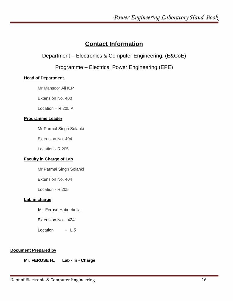
Contact Information
Department – Electronics & Computer Engineering. (E&CoE)
Programme – Electrical Power Engineering (EPE)
Head of Department.
Mr Mansoor Ali K.P
Extension No. 400
Location – R 205 A
Programme Leader
Mr Parmal Singh Solanki
Extension No. 404
Location - R 205
Faculty in Charge of Lab
Mr Parmal Singh Solanki
Extension No. 404
Location - R 205
Lab in charge
Mr. Ferose Habeebulla
Extension No - 424
Location - L 5
Document Prepared by
Mr. FEROSE H., Lab - In - Charge