Embed Size (px)
Citation preview

D800053X042July 2013
Quick Start Guide for DeltaV Power, Grounding,and Surge Suppression

Printed in the Republic of Singapore.
© Emerson Process Management 1996 - 2013. All rights reserved. For Emerson Process Management trademarks and service marks,go to Emerson Process Management Trademarks and Service Marks. All other marks are property of their respective owners. Thecontents of this publication are presented for informational purposes only, and while every effort has been made to ensure theiraccuracy, they are not to be construed as warranties or guarantees, expressed or implied, regarding the products or servicesdescribed herein or their use or applicability. All sales are governed by our terms and conditions, which are available on request. Wereserve the right to modify or improve the design or specification of such products at any time without notice.
See the CE statement in Chapter 1.
Emerson Process Management Distribution Ltd. Process Systems and SolutionsMeridian EastMeridian Business ParkLeicester, LE19 1uX, UK
Emerson a.s.European System and AssemblyPieštanská 1202/44Nové Mesto nad Váhom 91528Slovakia
Fisher-Rosemount Systems, Inc. – an Emerson Process Management company1100 W. Louis Henna Blvd.Round Rock, TX 78681

Contents
Chapter 1 Welcome ....................................................................................................................... 1DeltaV version this manual supports ....................................................................................................... 1Related DeltaV information .....................................................................................................................1CE statement ..........................................................................................................................................2Warning, Caution, Important, and Note .................................................................................................. 2
Chapter 2 Introduction .................................................................................................................. 5
Chapter 3 The basic premise .......................................................................................................... 7
Chapter 4 The reasons for grounding ............................................................................................. 9
Chapter 5 Ground cable sizing ......................................................................................................11
Chapter 6 Establishing and maintaining clean power ................................................................... 13Clean power options ............................................................................................................................. 17Single AC source ....................................................................................................................................18Two AC sources ..................................................................................................................................... 19
Chapter 7 DeltaV power and grounding options ...........................................................................21S-series ..................................................................................................................................................21CHARMs ................................................................................................................................................ 27SIS ......................................................................................................................................................... 32
Power supply configuration ....................................................................................................... 34Incorporating M-series SLS into S-series .....................................................................................36
Multiple Distributed Enclosures: Power and Grounding Schemes .......................................................... 38Floating AC and high-resistance ground ................................................................................................ 42
Chapter 8 Grounding topologies .................................................................................................. 45Star or single-point ground ....................................................................................................................45Mesh star ground network .................................................................................................................... 46Hybrid star mesh ground network ......................................................................................................... 48
Appendices and referenceAppendix A Interference and transients .......................................................................................... 49
Static (capacitive) coupling ................................................................................................................... 49Voltage differentials ..............................................................................................................................50Inductive coupling .................................................................................................................................51
Appendix B High integrity ground systems ..................................................................................... 53Highest integrity systems have shields connected to chassis ground .....................................................53
Appendix C Checklists for verifying site ground .............................................................................. 55Site ground verification checklists ......................................................................................................... 55Checklists ..............................................................................................................................................55
Good engineering practices for general systems ........................................................................56Environmental conditions ..........................................................................................................57Power and grounding connections ............................................................................................ 58Power and grounding connections with triad .............................................................................60General field device installation ................................................................................................. 61
Contents
i

I/O wiring (conventional, HART, serial, and bus types) ............................................................... 63Enclosures ................................................................................................................................. 65AC power system and distribution ............................................................................................. 68DC power system and distribution ............................................................................................. 69DeltaV controllers ......................................................................................................................71List of equipment used .............................................................................................................. 73
Appendix D References ................................................................................................................... 75
Contents
ii

1 WelcomeTopics covered in this chapter:
• DeltaV version this manual supports
• Related DeltaV information
• CE statement
• Warning, Caution, Important, and Note
This manual is a quick start guide for providing power, grounding, and surge suppressionfor Emerson's new CHARM and S-series products. Parts of this manual also apply to DeltaVM-series products as well. More specifically, this manual explains how to properly designand prepare control system electrical power and ground networks before you install yourDeltaV system. Applying the information in this manual saves time and expense bysignificantly increasing the reliability of your control system and by making your systemeasier to start up and maintain.
The power and grounding techniques described in this manual are based on bestengineering practices and industry standards. In addition to this manual, you may needother DeltaV and industry publications to obtain complete information for preparing yoursite. References to related industry standards can be found at the end of this document.
DeltaV version this manual supportsThe information in this manual applies to all versions of DeltaV systems; however the focusof this manual is on S-series equipment. Periodically, this manual is updated to incorporatesite preparation information for the newest DeltaV products and to add information basedon user feedback. To make sure you have the latest edition, contact your Emerson ProcessManagement local business partner or field sales office (LBP/FSO).
NoteBecause this manual covers all DeltaV versions and various OEM products, it often uses genericsymbols in drawings instead of exact product representations. See DeltaV and OEM manuals forexact representations.
Related DeltaV informationAdditional information is included on product DVDs, on Emerson Process Managementweb sites, and in printed manuals. Your Emerson Process Management local businesspartner or field sales office (LBP/FSO) can help you obtain the information you need.
Site Preparation and Design for DeltaV Digital Automation Systems covers power andgrounding for M-series and previous releases of SIS products. It also contains valuableinformation such as EMI, ESD, and environmental precautions.
Welcome
1

DeltaV product data sheets include descriptions, features, benefits, specifications, andordering information that are of particular importance to site preparation. Product datasheets are available from LBP/FSO.
DeltaV Books Online and context-sensitive help are embedded in DeltaV system softwareand are viewable after the software has been installed. Manuals needed to install and startup DeltaV products are shipped with the software in Adobe PDF format on the DeltaVDocumentation Library disk. In addition to this manual, manuals included on the DeltaVDocumentation Library disk include:
• DeltaV S-series and CHARMs Hardware Installation describes installation procedures,including details of screw terminal connections on power supplies and carriers.
• DeltaV S-series and CHARMs Hardware Reference contains specifications, wiringdiagrams, dimensions, and other reference information for S-series and CHARMshardware components.
• Getting Started with Your DeltaV Digital Automation System describes startup andoperating procedures.
• Fieldbus Installations in a DeltaV Digital Automation System describes planning forinstalling FOUNDATION Fieldbus systems.
• Installing Your DeltaV Safety Instrumented System Hardware describes installation,including details of screw terminal connections and wiring for smart logic solvers,SISNet repeaters, and other safety instrumentation hardware.
• DeltaV Safety Instrumented System Safety Manual describes how a DeltaV SafetyInstrumented System must be used for it to function as a safety instrumentedsystem.
• SIS Accessories Installation and Safety Manual describes how to properly install theSafety Relay Module and the Voltage Monitor Module.
Printed versions of many of these manuals can be ordered from your LBP/FSO. Users withGuardian or Foundation Support can access the manuals from the support website in PDFformat.
CE statementIf you intend to have your DeltaV system certified for compliance to appropriate EuropeanUnion directives, it must be installed in accordance with procedures described in themanual DeltaV S-series and CHARMs Hardware Installation.
Warning, Caution, Important, and NoteA Warning, Caution, Important, or Note identifies helpful or critical information. The typeof information included in each is:
Welcome
2

WARNING!
Warnings are installation, operation, or maintenance procedures, practices, conditions,statements, and so forth, which if not strictly observed, may result in personal injury or loss oflife.
CAUTION!
Cautions are installation, operation, or maintenance procedures, practices, conditions,statements, and so forth, which if not strictly observed, may result in damage to, ordestruction of, equipment or may cause long term health hazards.
ImportantInformation notices are installation, operation, or maintenance procedures, practices, conditions,statements, and so forth, which if not observed, may result in improper control system operation.
NoteNotes contain installation, operation, or maintenance procedures, practices, conditions, statements,and so forth, which alert you to important information which may make your task easier or increaseyour understanding.
Welcome
3

Welcome
4

2 Introduction
The information in this document helps you to properly connect power and ground toEmerson's CHARMs, S-series, and M-series products. For more information on otheraspects of site preparation please refer to the Site Preparation and Design for DeltaV DigitalAutomation Systems.
We realize that not all applications require the same level of grounding. In particular, sitesthat are mission critical (for example, pharmaceutical batch processes and nuclear powermonitoring),require the highest level of power, ground, and surge integrity andprotection.
Introduction
5

Introduction
6

3 The basic premise
All of the recommendations in this document are based on good engineering practice andapply to any control system. The following principles provide a foundation for systemdesign with respect to mitigating interference issues through power and grounding.
• Power, ground, and surge should always be considered together because theyfrequently interact. A system where power, ground, and surge suppression work inunison provides the most stable system.
• There is not a "magic hole" that we can dump all of our unwanted interference into.However by establishing a stable ground reference (preferably 1 Ω to 3 Ω) for thecontrol system, voltage events such as those caused by facility faults, dramatic loadchanges, or lightning that affect one area of the ground system will not adverselycause issues with the control system's ground reference.
• Noise (interference) always wants to return to its source following the path of leastresistance (Ohm's law)
If differences occur between this manual and local or regional codes and regulations,codes and regulations take precedence.
The basic premise
7

The basic premise
8

4 The reasons for grounding
• Safety ground (protective earth) — protects personnel from injury resulting fromdefective supply feeds. For example, if the insulation of the line side of a 120 VACpower conductor becomes frayed, causing the conductor to be in direct contactwith a properly grounded metal enclosure, a protective interrupt, such as a fuse orcircuit breaker, opens. The ground conductor must be sized as large as themaximum AC conductor feeding the load. This conductor should follow the samepath as the line conductors to their source, that is, first disconnect or separatelyderived source.
• High frequency ground — ground systems that improve signal integrity byreducing noise caused by machinery such as variable speed drives, welders, orcommutated DC motors. Interference and transients from other instrumentationand equipment is also greatly reduced with a properly constructed high frequencyground system. Skin effect causes high frequency signals to travel closer to thesurface of conductors. For this reason only the outermost part of cables actuallycarry the high frequency interference. For example, a 500 KHz signal uses 100% ofthe copper in a 33 AWG wire, but only 36% of the copper in a 19 AWG wire. Highfrequency with respect to control systems often encompasses a broad band offrequencies starting as low as 10 kHz.
• Stable DC reference ground — A low impedance ground (1 Ω to 3 Ω between theground system—triad or plant grid—and earth) maintains the control system at astable reference. Utility power and lightning systems should have their owngrounding systems. For safety reasons all grounds shall be connected together.However, there is finite impedance interconnecting each ground system. There arealso impedance variations between all points of the same system. When a disruptiveevent occurs, a short duration voltage gradient is established at the location wherethe fault makes contact with the localized ground. By assuring that the controlsystem has a low impedance to its DeltaV Instrument Ground (DIG), events thatoccur in one area of the ground system (typically due to lightning, load shifting, orfaulty utilities) that cause a gradient elevation proximal to it does not have assignificant an effect on the DeltaV Instrumentation Ground (DIG) potential.
• Lightning protection — protects property and personnel from lightning strokes.
• Lightning mitigation — protects equipment from induced energy as a result oflightning. This is accomplished through the interconnection and close proximity ofall of the DeltaV grounding systems. All metal enclosures are connected to thesafety ground system. Separately derived systems, such as isolation transformersand UPSs, should be as close to the DeltaV systems as possible. Case studies haveshown that induced energy as a result of lightning strokes has disrupted and evendamaged instrumentation equipment due to variance in ground potentials atmultiple locations. By keeping all metal as closely interconnected as possible withthe safety ground system any induced voltage quickly equalizes. This goal is realizedby multiple eddy current paths, minimizing the need for any single conductor toshunt the equalization current.
The reasons for grounding
9

The reasons for grounding
10

5 Ground cable sizing
DeltaV is a ground referenced system. To maintain high integrity it is important thatcareful consideration be paid to ground conductor sizing. The original site preparationmanual, Site Preparation and Design for DeltaV Digital Automation Systems, lists some typicalmethods of connecting grounding networks. More grounding networks can be found inthe section of this document on Grounding Topologies. Typically for large high-integritysystems, shields are connected to the chassis ground bar. One of the most cost efficientgrounding method uses a star topology with larger conductor sizes at the sections locateda greater distance from the cabinets. The following tables are applicable for all DeltaVproducts. Table 5-1 lists the appropriate wire size with respect to the distance between acabinet and the closest ground bar or between individual ground bars. Cable sizes aredetermined based on the number of I/O points associated with that particular section ofcable. The overall distance from an enclosure to the earthing point at the DeltaVInstrument Ground (DIG) should not exceed 300 feet. The braided cable in Table 5-2 maybe used as an alternative as shown in Table 5-3 for the cable in Table 5-1. Single enclosuresor a group of adjacent enclosures with a relatively small number of I/O points may connectthe chassis ground and the DC ground buses together at the cabinet provided the wiresize, distances, and I/O points are within the specifications listed in Table 5-4.
Ground wire sizing Table 5-1:
I/O points
Cable length (ft)
10 25 50 100 300
64 8 AWG 8 AWG 8 AWG 6 AWG 2 AWG
128 8 AWG 8 AWG 6 AWG 2 AWG 1/0
256 8 AWG 6 AWG 2 AWG 1/0 2/0
512 6 AWG 2 AWG 1/0 2/0 3/0
1024 2 AWG 1/0 2/0 3/0 4/0
2048 1/0 2/0 3/0 4/0 ---
4096 2/0 3/0 4/0 --- ---
8192 3/0 4/0 --- --- ---
Flat-braided PVC-insulated cable alternative Table 5-2:
New England Wire Technolo-gies number Description Certification
N30-36T-762-2ULG 48-22-36 TINNED COPPER FLATBRAID
UL AWM 1680 105C, VNS
N30-30T-652-2UL 48-22-36 TINNED COPPER FLATBRAID
UL AWM 1680 105C, VNS
Ground cable sizing
11

Braided cable system Table 5-3:
I/Opoints
Braided cable length (ft)
10 25 50 100
128 N30-36T-762-2ULG N30-36T-762-2ULG N30-36T-762-2ULG N30-30T-652-2UL
256 N30-36T-762-2ULG N30-36T-762-2ULG N30-30T-652-2UL ---
512 N30-36T-762-2ULG N30-30T-652-2UL --- ---
1024 N30-30T-652-2UL --- --- ---
Single cable length with chassis ground and DC ground connected inenclosure
Table 5-4:
I/O points
Cable length (ft)
10 25 50 100
64 8 AWG 8 AWG 6 AWG 2 AWG
128 8 AWG 6 AWG 2 AWG 1/0
256 6 AWG 2 AWG 1/0 2/0
512 2 AWG 1/0 2/0 3/0
1024 1/0 2/0 3/0 4/0
Ground cable sizing
12

6 Establishing and maintaining cleanpowerTopics covered in this chapter:
• Clean power options
• Single AC source
• Two AC sources
To operate your DeltaV system at the highest level of integrity (that is, to maintain thesystem with the least amount of disruptive events due to power anomalies) a properlydesigned power conditioning system should be considered.
Clean-power with respect to alternating current used to power bulk supplies is a term thatdescribes the sinusoidal power that maintains its characteristics with both linear and non-linear loads. Some commonly used standards which address power quality are:
• IEEE Recommended Practice for Monitoring Electric Power Quality
• IEEE Recommended Practices and Requirements for Harmonic Control in Electrical PowerSystems
• IEC 61000-3-11 Electromagnetic compatibility (EMC) Limitations of voltage changes,voltage fluctuations and flicker in public low voltage supply systems
• IEC 61000-3-12 Electromagnetic compatibility (EMC) Limits for harmonic currentsproduced by equipment connected to public low voltage systems
Tables Table 6-1 and Table 6-2 list the most prevalent factors that influence the quality ofpower. Common causes for power quality issues with corresponding recommendations forcorrective measures can also be found in the tables.
ImportantAny three-phase source, such as transformer or UPS, providing power to a DeltaV system must onlypower DeltaV products, safety systems, or the control system. Therefore, no VFDs, HVAC, motors,fans, compressors, ballasts, and so on shall be connected to any output phase of a transformer orUPS that is also used to power the DeltaV system.
Potentially disruptive power issues typically solved with a UPSTable 6-1:
Type of interference Possible effectCommon cau-ses
Preventivemeasures Comment
Interruptions DeltaV restart Utility faults,load switching,breaker trips,or equipmentfailures
UPS DeltaV systems powered withEmerson bulk power suppliesare able to withstand power in-terruptions up to 20 ms.
Establishing and maintaining clean power
13

Potentially disruptive power issues typically solved with a UPS (continued)Table 6-1:
Type of interference Possible effectCommon cau-ses
Preventivemeasures Comment
Sag Possible DeltaVrestart if volt-age drops be-low lower pow-er supply limit.
Start-up loadsdrawing exces-sive current,equipmentfaults
UPS DeltaV systems powered withEmerson bulk power suppliesare able to withstand sags upto 20 ms.
Undervoltage Loss of powerto the DeltaVsystem.
Utility faults orload changes
UPS DeltaV powered with Emersonbulk power supplies are able towithstand loss of power up to20 ms.
Swell Possible powersupply damageif voltage re-mains at in-creased levelsgreater thanpower supplylimit.
Loads shifting,utility faults
UPS
Overvoltage Possible powersupply damageif voltage re-mains at in-creased levelsgreater thanpower supplylimit
Loads shifting,utility faults
UPS
Power quality issues solved with high quality UPSTable 6-2:
Type of interference Possible effectCommon cau-ses
Preventive meas-ures Comment
Impulse transient Impulse transi-ents in excessof 1500 V maydestroy chan-nel or system iftransient is onpower feeds.
Lightningcausing volt-age gradientsin excess of1500 V.
Appropriate surgeprotection devices(SPD) should beconsidered. TheSPD should be sizedfor the worst surgearea that either thepower or shieldsenter.
Typically, bulk suppliesare certified to have ei-ther double or rein-forced insulation towithstand 1500V. TheDeltaV system is pro-tected with transientvoltage suppression to1500V.
Establishing and maintaining clean power
14

Power quality issues solved with high quality UPS (continued)Table 6-2:
Type of interference Possible effectCommon cau-ses
Preventive meas-ures Comment
Oscillatory transient Data loss withpossible dam-age.
Overall systemresponse toimpulse orload switchingfrom inductiveor capacitiveloads.
Double conversionUPS with filtering.
EFI/RMI noise Data loss, sys-tem corrup-tion.
Transmitters,faulty equip-ment, ineffec-tive ground-ing, closeproximity toEMI/RFIsource.
Isolation transform-er ( common mode< 1.5MHz), filter(normal Node 10KHz to 10 MHz)UPS with filteredoutput
Notching Data loss, sys-tem corrup-tion.
Variable fre-quency drives,welders, light-ing.
Filters or UPS withfiltered output.
Isolate VFD's, Never al-low generating devi-ces, such as VFD's, touse the same powerfeed or an adjacent legon a three phase sys-tem.
Harmonics Overheatingwhich canshorten the lifeof power sup-plies.
Non-linearloads.
Could correct at thesource with Activeharmonic filter, K-factor transform-ers, power factorcorrection supplies
A double conversion uninterruptible power supply can also mitigate most power qualityissues.
Isolation transformers are an excellent means to significantly reduce common mode noise,typically up to 750 KHz. The isolation transformer also allows for a separately derivedsource of power that creates a stable ground reference point in close proximity with theDeltaV system. Filters are a readily-available solution for normal-mode noise reduction inthe range of a few hertz up to 10 MHz. Surge suppressor/filters are also available toprevent surge voltages from indirect lightning or large upstream power faults fromdamaging control equipment in addition to minimizing normal-mode noise. A powerquality evaluation of the site can easily determine the best solution to meet your individualrequirements.
UPSs that supply power to control systems should be double conversion types. Typically,their input voltage is provided from low voltage (100 VAC to 600 VAC) feeders, with either
Establishing and maintaining clean power
15

single or three-phase power. The AC power from the source is rectified to DC and used asleveling power to maintain batteries or to supply energy for a flywheel. The inverter stageproduces the AC sine wave output using power from the DC storage section - batteries or aflywheel. Only use UPSs that reproduce high quality sine waves. Some UPSs producemodified sine waves that are rich in harmonics and detrimental to control systems.
ImportantAny UPS supplying power to the DeltaV system shall be of the double conversion type, with aninverter stage which produces harmonic free sinusoidal output waveforms. Never use a UPS thatproduces modified sine waves.
Most UPSs provide a degree of protection from power failure, power sag, and powersurges. However, some UPSs provide an excellent solution for most of the power qualityissues found in Table 6-2. A bypass transformer with static switchover allowing for UPSmaintenance is either supplied as an integral component or can be connected externally tothe UPS. When selecting the bypass transformer note that if the UPS used is the type whichprovides the cleanest power, then a shielded bypass transformer would be a better choicethan a standard transformer.
Some UPSs provide three-phase output power. When using a UPS with a three-phaseoutput, all phases should be connected only to the control system and to non-interferingequipment. Never connect one phase to the DeltaV system and another phase to a VFD.
Isolation transformers have been successfully used for many years to supply clean-powerfor control systems, medical systems, and computer centers. The Isolation transformeralso provides a location to establish a separately derived ground.
For a comparison of the attenuation benefits for the various degrees of shielding availablesee Table 6-3. In addition to the common-mode rejection provided by isolationtransformers, many transformers can be purchased with filters on their output stage. Thefilter attenuates the normal-mode noise. Shielded transformers with filtered outputsprovide noise reduction from a few hertz to up to 750 KHz in both common and normalmode.
Transformer attenuationTable 6-3:
Type of shielding Attenuation ratio Typical attenuation
No shield 10:1 12 dB to 20 dB
Single shield 1000:1 50 dB to 60 dB
Double shield 10,000:1 65 dB to 90 dB
Triple shield 100,000:1 90 dB to 120 dB
Most industrial applications share power with a wide variety of devices including largemotors, furnaces, large lighting systems, and HVAC systems. Control applications that cantolerate disruptive events require little or limited consideration with respect to the PowerDistribution Unit (PDU). However, if the application requires a high degree of consistentsystem integrity with minimal disruption, then the proper PDU should be used. Figure 6-1 isa tool to help determine the most economical and effective configuration for your site's ACpower requirements with respect to interruptions and noise mitigation.
Establishing and maintaining clean power
16

Clean power optionsThere are a number of ways to provide clean power. To find the correct solution for yoursite, follow the flowchart in Figure 6-1 and choose the proper options below.
AC power source flowchartFigure 6-1:
Is Power Failure, Sag, or Surge
present?
Is Noise, which couldpotentially cause disruptive
events present?
Yes, use a UPSNo
Is Noise, which couldpotentially cause disruptive
events, present?
Evaluate Power needs for
DeltaV Site
Use UPS(s) with at least
Power FailurePower SagPower SurgeUndervoltage protectionOvervoltage Protection
No
Use UPS(s) with
Power FailurePower SagPower SurgeUndervoltage protectionOvervoltage ProtectionLine noise eliminationFrequency variation correctionSwitching Transient filterHarmonic Interference filter
Yes
Is Power Source in close proximity
(< 100 m) to DeltaV?
No
Use Transformer or UPS(s) to Establish a Separately
derived ground reference at DeltaV DIG
No
Chose Number of AC Sources required
Use an Isolation Transformerand Suppressor/Filter or Filter in close proximity to Bulk Supply
Or
Use UPS(s) with
Power FailurePower SagPower SurgeUndervoltage protectionOvervoltage ProtectionLine noise eliminationFrequency variation correctionSwitching Transient filterHarmonic Interference filter
Yes
Is Noise at Frequencies > 10KHz
a present?
Yes
Use anIsolation Transformer
Yes
No
Establishing and maintaining clean power
17

CAUTION!
When NOT using a separately derived ground system with interference levels equal to or lowerthan stipulated in EN 61000-3-12 and EN 61000-3-11 and when no noise such as described in Table 6-1 and Table 6-2 is present, then at no time following the installation of DeltaV shallinterference be permitted if high integrity is desired.
Single AC source
Option A
Highest integrity
• UPS with the following features:
- Neutral/ground bond point to establish a separately derived ground reference
- Power failure, power sag, and power surge protection
- Capable of regulating under-voltage and over-voltage input power
- Line noise elimination, frequency variation correction, switching transient filterharmonic interference filter
• UPS to DeltaV cabinet distance of less than 100 meters
• Surge suppressor/filter prior to bulk supply
• Bypass isolated transformer with single isolated shielding
• Power lines in armored cable or metal conduit (optional)
Option B
• UPS with the following features:
- Neutral/ground bond point to establish a separately derived ground reference
- Power failure, power sag, and power surge protection
- Capable of regulating under-voltage and over-voltage input power
• UPS to DeltaV cabinet distance of less than 100 meters
• Surge suppressor/filter prior to bulk supply (optional if signal shields are not locatedin Zone 0 or Zone 1 lightning area)
• Bypass isolated transformer with single isolated shielding
• Power lines in armored cable or metal conduit (optional)
Option C
• Isolation transformer
• Neutral/ground bond point to establish a separately derived ground reference
• Transformer to DeltaV cabinet distance of less than 100 meters
• Surge suppressor/filter prior to bulk supply (optional if signal shields are not locatedin Zone 0 or Zone 1 lightning area)
Establishing and maintaining clean power
18

• Power lines in armored cable or metal conduit (optional)
Option D (clean-power: AC source <100 m)
• Surge suppressor/filter prior to bulk supply (optional if signal shields are not locatedin Zone 0 or Zone 1 lightning area)
• Power lines in armored cable or metal conduit (optional)
Option E (clean-power: AC source < 300m)
• Surge suppressor/filter prior to bulk supply
• Power lines in armored cable or metal conduit
Two AC sourcesOption F
Highest integrity
AC source 1 and 2
• UPS with the following features:
- Neutral/ground bond point to establish a separately derived ground reference
- Power failure, power sag, and power surge protection
- Capable of regulating under-voltage and over-voltage input power
- Line noise elimination, frequency variation correction, switching transient filterharmonic interference filter
• UPS to DeltaV cabinet distance of less than 100 meters
• Surge suppressor/filter prior to bulk supply
• Bypass isolated transformer with single isolated shielding
• Power lines in armored cable or metal conduit (optional)
Option G
Highest integrity
AC source 1
• UPS with the following features:
- Neutral/ground bond point to establish a separately derived ground reference
- Power failure, power sag, and power surge protection
- Capable of regulating under-voltage and over-voltage input power
- Line noise elimination, frequency variation correction, switching transient filterharmonic interference filter
• UPS to DeltaV cabinet distance of less than 100 meters
• Surge suppressor/filter prior to bulk supply
Establishing and maintaining clean power
19

• Bypass isolated transformer with single isolated shielding
• Power lines in armored cable or metal conduit (optional)
AC source 2
• Isolation transformer
• Neutral/ground bond point to establish a separately derived ground reference
• Transformer to DeltaV cabinet distance of less than 100 meters
• Surge suppressor/filter prior to bulk supply
• Power lines in armored cable or metal conduit (optional)
Option H
AC sources 1 and 2
• Isolation transformer
• Neutral/ground bond point to establish a separately derived ground reference
• Transformer to DeltaV cabinet distance of less than 100 meters
• Surge suppressor/filter prior to bulk supply
• Power lines in armored cable or metal conduit (optional)
Option I (clean-power: AC source < 100m)
AC sources 1 and 2
• Surge suppressor/filter prior to bulk supplies (optional if signal shields are notlocated in Zone 0 or Zone 1 lightning area)
• Power lines in armored cable or metal conduit (optional)
Option J (clean-power: AC source < 300m)
AC sources 1 and 2
• Surge suppressor/filter prior to bulk supplies
• Power lines in armored cable or metal conduit
Establishing and maintaining clean power
20

7 DeltaV power and grounding optionsTopics covered in this chapter:
• S-series
• CHARMs
• SIS
• Multiple Distributed Enclosures: Power and Grounding Schemes
• Floating AC and high-resistance ground
DeltaV systems are certified as Separated or Safety Extra Low Voltage (SELV) systems. AnSELV system is "an extra-low voltage system which is electrically isolated from the earthand from other systems in such a way that a single fault cannot give rise to the risk ofelectric shock."(1) Therefore, the DeltaV DC reference ground maintains a stable low noisereference for the DeltaV signal returns and DC power supply commons.
S-seriesPower and grounding of the DeltaV S-series is connected in a manner similar to that of theM-series products. To convert AC power to the 24 VDC power required for products suchas S-series system power supplies, CHARM I/O Card (CIOC), Safety Integrated System (SIS)products, and DC field power, a bulk power configuration as shown in Figure 7-1 producesa high-integrity solution. It is sometimes preferable to create a separate AC to DC panelthat is only accessible by qualified electricians. If an S-series system only contains DC I/Ocards, then field technicians can service the DeltaV panels without working near highervoltage AC sources.
Typically, the 100 VAC to 230 VAC at 50 Hz or 60 Hz is supplied from power disconnectpanels fed from double conversion uninterruptable power supplies (UPS) or throughisolation transformers to the AC panel. A sufficiently sized disconnect is usually locatedprior to each bulk power supply. The two bulk supplies of Figure 7-1 are then fed into a dualredundancy module to power the DeltaV system bus. If one of the AC feeds fails or one ofthe bulk power supplies fails, the redundancy module shifts the load to the remainingpower supply. However, the configuration of Figure 7-1 allows for the possibility of up totwo separate single points of failure:
• the Dual Redundancy Module
• if only one DeltaV System Power supply was used as shown in Figure 7-2, then thesingle system power supply is also a single point of failure.
All configurations should be weighed from a cost-benefit perspective. Therefore, if thehighest integrity S-series system is required the combination of a power panel as shown in Figure 7-3 with the redundant S-series system of Figure 7-4 should be used. The two-widewith redundant system supplies provides injected power allowing the maximum currentfor a total of 15 A on an S-series node.
(1) BS 7671:2008 Requirements for Electrical Installations, IET Wiring Regulations 17th Edition, 2008
DeltaV power and grounding options
21

Typical power panel for DeltaV systemsFigure 7-1:
Fuse T
B
Fuse T
B
Fuse T
B
Fuse T
B
Fuse T
B
Fuse T
B
CB1 CB2 CB3 CB4
AC
100-240V
N+ + ––
L
Parallel
Single
+24VDC
960W/1440W
AC/DCPowerSupply
PS1
AC
100-240V
N+ + ––
L
Parallel
Single
+24VDC
960W/1440W
AC/DCPowerSupply
PS2
AC
100-240V
N+ + ––
L
Parallel
Single
+24VDC
960W/1440W
AC/DCPowerSupply
PS3
AC
100-240V
N+ + ––
L
Parallel
Single
+24VDC
960W/1440W
AC/DCPowerSupply
PS4
Field Power+24VDC
DeltaV Power+24VDC
PrimaryAC Power
SecondaryAC Power
PE
Enclosure (A)
Enclosure (C)
Enclosure (B)
Enclosure PE Ground Lug
Enclosure Door
Adjacent Enclosure 6 AWG minimum
Enclosure (A)
Enclosure (C)
Enclosure (B)
Input 1
DC 24-28V
40A
Input 2
DC 24-28V
40A
OutputMax.80A
Chassis
Ground
Dual
Redundancy
Module
+ –
+ – + –
Input 1
DC 24-28V
40A
Input 2
DC 24-28V
40A
OutputMax.80A
Chassis
Ground
Dual
Redundancy
Module
+ –
+ – + –
NoteThe 24 VDC return (-) terminal of the power supplies must be connected to DeltaV DC ground. This isaccomplished as shown in Figure 7-2 from the bused DC ground wire connected to the DC groundbus.
DeltaV power and grounding options
22

S-series power and groundingFigure 7-2:
Field
Power+24VDC
DeltaV
Power+24VDC
… Field Devices as required
14 AWG
Chassis Ground
(CG)DC Ground
Isolated Bus
Enclosure PE Ground Lug
Enclosure door
Adjacent Enclosure 6 AWG minimum To DIG To DIG
14
AWG
Jumper
Jumper
Jumper
Jumper
DeltaV power and grounding options
23

High integrity redundant power panel for DeltaV systemsFigure 7-3:
Fuse T
B
Fuse T
B
Fuse T
B
AC
100-240V
N+ + ––
L
Parallel
Single
+24VDC
960W/1440W
AC/DCPowerSupply
PS1
AC
100-240V
N+ + ––
L
Parallel
Single
+24VDC
960W/1440W
AC/DCPowerSupply
PS2
AC
100-240V
N+ + ––
L
Parallel
Single
+24VDC
960W/1440W
AC/DCPowerSupply
PS3
AC
100-240V
N+ + ––
L
Parallel
Single
+24VDC
960W/1440W
AC/DCPowerSupply
PS4
DeltaVField Power
+24VDC
Primary DeltaV Power
+24VDC
PrimaryAC Power
SecondaryAC Power
PE
Enclosure PE Ground Lug
Enclosure Door
Adjacent Enclosure 6 AWG minimumTo DIG
CB1 CB2 CB3 CB4
Input 1
DC 24-28V
40A
Input 2
DC 24-28V
40A
OutputMax.80A
Chassis
Ground
Dual
Redundancy
Module
+ –
+ – + –
SecondaryDeltaV Power
+24VDC
DeltaV power and grounding options
24

NoteThe 24 VDC return (-) terminal of the power supplies shall be connected to DeltaV DC ground. This isaccomplished as shown in Figure 7-4 from the DC ground wire connected to the DC ground bus.
DeltaV power and grounding options
25

S-series redundant power and groundingFigure 7-4: Field Power
+24VDC
Field Devices as required
Primary
DeltaV Power
+24VDC
14 AWG
14 AWG
14 AWG
Secondary
DeltaV Power
+24VDC
Chassis Ground
(CG)
DC Ground
Isolated Bus
Enclosure PE Ground Lug
Enclosure door
Adjacent Enclosure 6 AWG minimum To DIG To DIG
Jumper
Jumper
Jumper
14 AWG
DeltaV power and grounding options
26

CHARMsBecause CHARMs are typically used in remote locations they usually have dedicated localredundant power supplies. If CHARM I/O subsystems are powered from AC sources, thepower must be very clean. This clean-power is usually obtained by isolation transformerslocated in close proximity to the CHARM cabinet. It may be advantageous to use UPSs or acombination of a UPS for the primary power and an isolation transformer for the secondarypower. In addition to the UPS and isolation transformers, surge suppressors can be locatedjust before each bulk power supply. Most power surges are assumed to originate fromlightning. However, it is estimated that in an industrial environment 80% of disruptivesurges originate from the industrial power and equipment. Figure 7-5 shows one of thehighest integrity CHARM systems with respect to power and ground. The typical distancebetween the separately derived AC power source and the CHARM cabinet should be 100meters or less. To greatly reduce any chance of interfering noise coupling into the power-feed, use conductive metal conduit or armored cable between the separately derivedsource (UPSs or Isolation Transformers) and the CHARM enclosure.
ImportantCHARM extender cables DO NOT extend the shield bar from one group of baseplates to the next.Baseplate shields are connected to the Chassis Ground (CG) using 14 AWG wire from the AddressPlug terminal connection or the end terminator connection point. If extender cables are used andshielded signal cables are located on baseplates on both sides of the extender cables, separate shieldcables must be connected to the CG bar from each set of baseplates.
DeltaV power and grounding options
27

Highest integrity power and grounding for a CHARM enclosureFigure 7-5:
AC 100-240V
DC ok
N L
AC/DCPowerSupply
PS1
AC 100-240V
DC ok
N L
AC/DCPowerSupply
PS1
Isolated Bus
CHARM Enclosure
CB1 CB1
Communications with
DeltaV Should be
connected via Fiber-
optic cable for distance
exceeding 200 ft.
ChassisGround
(CG)
DC Ground
Follow LocalCodes
Follow LocalCodes
Follow LocalCodes
See Table 1for cable size
IsolationTransformer
IsolationTransformer
N
G
N
G
N
G
exceeding 200 ft.
DIG
Wire sized equal
or greater than
maximum power
feed
Building Steel
N
O
N
C
C
O
MG N L L GN
Filter/Surge
Suppression
Device
N
O
N
C
C
O
MG N L L GN
Filter/Surge
Suppression
Device
AC Feed 1
AC Feed 2
If the distance to the AC power source is short (less than a few meters); communication tothe DeltaV controller is through fiber; and there is no galvanic connection to any otherfield devices, then the chassis ground and DC ground can be connected together insidethe cabinet. This permits the use of one cable from the junction box (JB) to the next groundlocation. For example, if the optically isolated CHARM junction box (JB) is attached to thesteel girder on a drilling rig with the transformers also mounted to the steel directly underthe JB, then weld the ground bar to the steel close to the transformers to establish both aseparately derived safety ground and a JB DC ground. It is also optimal to maintain a lengthof less than 100 meters for the shielded signal wires in addition to assuring that signalwires are not in close proximity to interfering sources.
DeltaV power and grounding options
28

High integrity power and grounding for CHARM enclosureFigure 7-6:
N L N L
N
G
N
G
AC 100-240V
DC ok
AC/DCPowerSupply
PS1
AC 100-240V
DC ok
AC/DCPowerSupply
PS1
DIG
Isolated Bus
Wire sized equalor greater than
maximum powerfeed
CHARM Enclosure
CB1 CB1
Communications with
DeltaV Should be
connected via Fiber-
optic cable for distance
exceeding 200 ft.
AC Feed 1
Building Steel
ChassisGround
(CG)
DC Ground
Follow LocalCodes
Follow LocalCodes
Follow LocalCodes
See Table 1for cable size
IsolationTransformer
IsolationTransformer
AC Feed 2
DeltaV power and grounding options
29

Power and grounding for CHARM enclosure with clean powerFigure 7-7:
N L N L
AC 100-240V
DC ok
AC/DCPowerSupply
PS1
AC 100-240V
DC ok
AC/DCPowerSupply
PS2
DIG
Isolated Bus
CHARM Enclosure
CB1 CB1
Communications with
DeltaV Should be
connected via Fiber-
optic cable for distance
exceeding 200 ft.
Building Steel
ChassisGround
(CG)
DC Ground
Follow Local
Codes
See Table 1
for cable size
Power should be at or better than stated in
EN 61000-3-12
EN 61000-3-11
Electromagnetic compatibility (EMC) – Part 3-12:
Limits for harmonic currents produced
by equipment connected to public low-
voltage systems with input current >16 A
and ≤75 A per phase
Electromagnetic compatibility (EMC) – Part 3-11:
Limitation of voltage changes, voltage
fluctuations and flicker in public low-
voltage supply systems – Equipment
with rated current ≤75 A and subject to
conditional connection
Ground connection from Power Source
not necessary if power is controlled
with an Active Harmonic Filter
A separately derived ground is maintained by the use of a DC/DC power converter. TheDC/DC converter also assures criteria A is maintained as stated in IEC 60000-4-29. Figure 7-8 shows the placement of the DC/DC supplies when the converters are not locatedin the CHARM enclosure and Figure 7-9 depicts the typical configuration when the DC/DCconverters are located in the same enclosure as the CHARM system.
DeltaV power and grounding options
30

Remote DC solution for CHARM power and groundingFigure 7-8:
Output Nominal
+24VDC 10 A
Input
+18-32VDC 10 A
DC/DCPowerSupply
PS1
Output Nominal
+24VDC 10 A
Input
+18-32VDC 10 A
DC/DCPowerSupply
PS1
Isolated Bus
Up to 100 ft.
CHARM Enclosure
CB1
Communications with
DeltaV should be
connected via Fiber-
optic cable for distance
exceeding 200 ft.
ChassisGround
(CG)
DC Ground
Follow Local
Codes for
PE Ground
+24VDC
Nominal
See Table 1
for cable size
DIG
Building Steel
CB1
DeltaV power and grounding options
31

Localized DC solution for CHARM power and groundingFigure 7-9:
Output Nominal
+24VDC 10 A
Input
+18-32VDC 10 A
DC/DCPowerSupply
PS1
Output Nominal
+24VDC 10 A
Input
+18-32VDC 10 A
DC/DCPowerSupply
PS1
Isolated Bus
CHARM Enclosure
CB1
Communications with
DeltaV should be
connected via Fiber-
optic cable for distance
exceeding 200 ft.
Chassis Ground (CG)DC Ground
Follow Local
Codes for
PE Ground
+24VDC
Nominal
+24VDC
Nominal
See Table 1 for cable size
DIG
Building Steel
CB1
SISThe M-series SIS products are easily integrated into an S-series system by connecting theSIS adaptor module either to the right of the S-Series 2-wide carrier, after the S-series8-wide carrier, or after the S-series left extender. DC power with the highest integrity isprovided as shown in #unique_23/fig_CECEFAAD704F48C4A803FE4F62162F82. Two AC/DC
DeltaV power and grounding options
32

power supplies are combined through a redundancy module to feed the 24 VDC to onegroup of SLSs or SISNet Repeaters while two other AC/DC power supplies through anotherredundancy module provide the DC power for the SLSs or SISNet Repeaters partners (see Figure 7-11). Whenever possible it is preferable to run the 24 VDC positive and 24 VDCreturn together as a twisted pair. When the power is brought to the SIS panel as in Figure 7-11, both groups of DC returns may be bused together at the terminal blocks.
DeltaV power and grounding options
33

Power supply configuration
Typical SLS power panel with maximum supply redundancyFigure 7-10:
PS1
Secondary SLS Power
24VDC
CB1
PS2
CB2
PS1
N L
AC 100-
240V
Parallel
Single
DC 24V
960W/1440W
AC/DC
Power
Supply
Input 1
DC 24-28V
40A
Input 2
DC 24-28V
40A
Output
Max.
80A
Chassis
Ground
Dual
Redundancy
Module
N L
AC 100-
240V
Parallel
Single
DC 24V
960W/1440W
AC/DC
Power
Supply
Fuse
TB
PS3
CB3
PS4
CB4
PS3
N L
AC 100-
240V
Parallel
Single
DC 24V
960W/1440W
AC/DC
Power
Supply
Input 1
DC 24-28V
40A
Input 2
DC 24-28V
40A
Output
Max.
80A
Chassis
Ground
Dual
Redundancy
ModulePS4
N L
AC 100-
240V
Parallel
Single
DC 24V
960W/1440W
AC/DC
Power
Supply
Fus e
TB
Primary SLS Power
24VDC
Primary
AC Power
Secondary
AC Power
PE
6 AWG minimum
G N L L GN
N
O
N
C
C
O
M
Filter/
Surge
Suppression
Device
G N L L GN
N
O
N
C
C
O
M
Filter/
Surge
Suppression
Device
G N L L GN
N
O
N
C
C
O
M
Filter/
Surge
Suppression
Device
G N L L GN
N
O
N
C
C
O
M
Filter/
Surge
Suppression
Device
Note 1) Use either a combined Suppressor Filter
Module or a Type II or Type III Surge
Suppressor followed by a Filter sized
appropriatelyEnclosure PE Ground LugEnclosure doorAdjacent Enclosure
To DIG
DeltaV power and grounding options
34

NoteConnect the 24 VDC return (-) terminal of the power supplies to DeltaV DC ground. This isaccomplished as shown in Figure 7-11 from the bused DC ground wire connected to the DC Groundbus.
DeltaV power and grounding options
35

Incorporating M-series SLS into S-series
SLS highest integrity power and groundingFigure 7-11:
ROW 1
+24VDC
Return
+24VDC
Primary
ROW 1 ROW NROW N
ROW 1
+24VDC
Return
+24VDC
Primary
ROW 1 ROW NROW N
ROW 1
SLS 1B
ROW N
SLS 1A
ROW N
SLS 1B
ROW N
SLS 2A
ROW N
SLS 2B
ROW N
SLS 3A
ROW N
SLS 3B
ROW N
SLS 4A
ROW N
SLS 4B
ROW N
SIS-NET
1A
ROW N
SIS-NET
1B
ROW 1
SLS 2B
ROW 1
SLS 1B
ROW 1
SLS 2B
ROW 1
SLS 3B
ROW 1
SLS 4B
ROW 1
SLS 3B
ROW 1
SLS 4B
32 Logic Solvers Total
Row N
14 AWG
Isolated Bus
Chassis Ground (CG)
Install 120 ohm
terminators on
one-wide carrier
DC Ground
Enclosure PE Ground Lug
Enclosure door
Adjacent Enclosure 6 AWG minimumTo DIGTo DIG
SLS Power
Primary
+24VDC
SLS
Secondary
+24VDC
DeltaV
Power
+24VDC
14
AWG
Size wire
per max.
current
capacity
DeltaV power and grounding options
36

Figure 7-12 shows an option for powering a redundant SLS safety system from one pair ofredundant power supplies where the redundancy is provided from two AC/DC powersupplies that are combined through a redundancy module as seen in one group in #unique_23/fig_CECEFAAD704F48C4A803FE4F62162F82. Ground the SIS power supplyreturn, DeltaV power supply return, and system power supply return at the DC ground bus.
SLS high integrity power and groundingFigure 7-12:
32 Logic Solvers Total
SLS Power
+24VDC
DeltaV
Power
+24VDC
14
AWG
Size wire
per max.
current
capacity
ROW 1
+24VDC
Return
ROW 1 ROW NROW N
+24VDC
Row N
14 AWG
Isolated Bus
Chassis Ground (CG)
DC Ground
Enclosure PE Ground Lug
Enclosure door
Adjacent Enclosure 6 AWG minimumTo DIGTo DIG
Install 120 ohm
terminators on
one-wide carrier
DeltaV power and grounding options
37

NoteThe 24 VDC that powers the railbus through the system power supply should be a separate powersource from the 24 VDC power supplying the SIS products if S-series cards and SIS cards are in thesame system. However, if the entire DeltaV system consists of the system power supplies,controllers, and safety products (Logic Solvers and SISNet Repeaters) then the controller and safetysystem power can be supplied from the same power source.
Multiple Distributed Enclosures: Power andGrounding Schemes
Grounding with multiple distributed enclosuresFigure 7-13:
Bypass
Transformer
Battery Bank or
Flywheel Storage
Sta
tic B
yp
ass
Sw
itch
N
G
Secondary UPS
Rectifier Inverter
Isolated BusBuilding Steel
Building Steel
DIG
Instrument Enclosure 1
Chassis
Ground
(CG)
Enclosure
door
Enclosure PE
Ground Lug
AC
Secondary
1
DeltaV
Primary
Power
+24VDC
AC
Primary
1
DeltaV
Secondary
Power
+24VDC
DC
Ground
Isolated
Bus
N
L
PE+24VDC
+24VDC
N
L
PE+24VDC
+24VDC
Instrument Enclosure 2
Chassis
Ground
(CG)
Enclosure
door
Enclosure PE
Ground Lug
AC
Secondary
2
DeltaV
Primary
Power
+24VDC
AC
Primary
2
DeltaV
Secondary
Power
+24VDC
DC
Ground
Isolated
Bus
N
L
PE+24VDC
+24VDC
N
L
PE+24VDC
+24VDC
Instrument Enclosure N
Chassis
Ground
(CG)
Enclosure
door
Enclosure PE
Ground Lug
AC
Secondary
N
DeltaV
Primary
Power
+24VDC
AC
Primary
N
DeltaV
Secondary
Power
+24VDC
DC
Ground
Isolated
Bus
N
L
PE+24VDC
+24VDC
N
L
PE+24VDC
+24VDC
NE
UT
RA
L
GR
OU
ND
LIN
E
Power Disconnect Panel
1
2
N
AC Secondary 1
AC Secondary 2
AC Secondary N
AC Feed 2
Bypass
Transformer
Battery Bank or
Flywheel Storage
Sta
tic B
yp
ass
Sw
itch
N
G
Primary UPS
Rectifier Inverter
NE
UT
RA
L
GR
OU
ND
LIN
E
Power Disconnect Panel
1
2
N
AC Secondary 1
AC Secondary 2
AC Secondary N
AC Feed 1
Shield
Bar
Shield
Bar
Shield
Bar
DeltaV power and grounding options
38

Any DeltaV system (M-series, S-series, or CHARMs) can be configured as shown in Figure 7-13. The highest integrity system has both UPSs located in the same area as all ofthe DeltaV enclosures. An equally high integrity configuration would have one UPS andone filtered isolation transformer in addition to surge suppressors in all of the enclosures.The ground bus-bar shown in Figure 7-13 and Figure 7-14 located just prior to the DIG onlyrequires one conductor leading to the actual earth ground point.
For example, on a multi-story building or platform, as the DeltaV grounds leave the floor,both the DC ground and chassis ground are connected to a common ground that is eitherwelded to building steel or bolted using conductive grease on the bonding surfaces tobuilding steel. The vertical ground run to the actual DeltaV instrument ground only needsto be a single cable sized as shown in Table 5-1 or Table 5-4. If the total length exceeds 300feet then the 4/0 cable is adequate. In addition, if the DeltaV equipment is located in amultistory structure every other floor can be connected together.
Close proximity enclosures with chassis and DC grounds togetherFigure 7-14:
6 AWG minimum
Bypass
Transformer
Battery Bank or
Flywheel Storage
Sta
tic B
ypass
Sw
itch
N
G
Secondary UPS
Rectifier Inverter
Building Steel
DIG
Instrument Enclosure 1
Chassis
Ground
(CG)
Enclosure
door
Enclosure PE
Ground Lug
AC
Secondary
1
DeltaV
Primary
Power
+24VDC
AC
Primary
1
DeltaV
Secondary
Power
+24VDC
DC
Ground
Isolated
Bus
Shield
Bar
N
L
PE+24VDC
+24VDC
N
L
PE+24VDC
+24VDC
Instrument Enclosure 2
Chassis
Ground
(CG)
Enclosure
door
Enclosure PE
Ground Lug
AC
Secondary
2
DeltaV
Primary
Power
+24VDC
AC
Primary
2
DeltaV
Secondary
Power
+24VDC
DC
Ground
Isolated
Bus
Shield
Bar
N
L
PE+24VDC
+24VDC
N
L
PE+24VDC
+24VDC
Instrument Enclosure N
Chassis
Ground
(CG)
Enclosure
door
Enclosure PE
Ground Lug
AC
Secondary
N
DeltaV
Primary
Power
+24VDC
AC
Primary
N
DeltaV
Secondary
Power
+24VDC
DC
Ground
Isolated
Bus
Shield
Bar
N
L
PE+24VDC
+24VDC
N
L
PE+24VDC
+24VDC
NE
UT
RA
L
GR
OU
ND
LIN
EPower Disconnect Panel
1
2
N
AC Secondary 1
AC Secondary 2
AC Secondary N
AC Feed 2
N
G
Isolation Transformer
Filt
er
NE
UT
RA
L
GR
OU
ND
LIN
E
Power Disconnect Panel
1
2
N
AC Secondary 1
AC Secondary 2
AC Secondary N
AC Feed 1
6 AWG minimum 6 AWG minimum
DeltaV power and grounding options
39

If the I/O count is relatively small (less than 100 I/O points) or the cost benefit evaluationresults in the system not requiring the highest integrity, then the chassis ground may beconnected as shown in Figure 7-14.
Enclosure grounding with adjacent baysFigure 7-15:
Bypass
Transformer
Battery Bank or
Flywheel Storage
Sta
tic B
yp
ass
Sw
itch
N
G
Secondary UPS
Rectifier Inverter
Isolated BusBuilding Steel
Enclosire 2
Enclosure 3
Building Steel
DIG
Enclosure 1 Bay 1
Chassis
Ground
(CG)
Enclosure
door
Enclosure PE
Ground Lug
AC
Secondary
1
DeltaV
Primary
Power
+24VDC
AC
Primary
1
DeltaV
Secondary
Power
+24VDC
DC
Ground
Isolated
Bus
N
L
PE+24VDC
+24VDC
N
L
PE+24VDC
+24VDC
Enclosure 1 Bay 2
Chassis
Ground
(CG)
Enclosure
door
Enclosure PE
Ground Lug
AC
Secondary
2
DeltaV
Primary
Power
+24VDC
AC
Primary
2
DeltaV
Secondary
Power
+24VDC
DC
Ground
Isolated
Bus
N
L
PE+24VDC
+24VDC
N
L
PE+24VDC
+24VDC
Enclosure 1 Bay N
Chassis
Ground
(CG)
Enclosure
door
Enclosure PE
Ground Lug
AC
Secondary
N
DeltaV
Primary
Power
+24VDC
AC
Primary
N
DeltaV
Secondary
Power
+24VDC
DC
Ground
Isolated
Bus
N
L
PE+24VDC
+24VDC
N
L
PE+24VDC
+24VDC
NE
UT
RA
L
GR
OU
ND
LIN
E
Power Disconnect Panel
1
2
N
AC Secondary 1
AC Secondary 2
AC Secondary N
AC Feed 2
Bypass
Transformer
Battery Bank or
Flywheel Storage
Sta
tic B
yp
ass
Sw
itch
N
G
Primary UPS
Rectifier Inverter
NE
UT
RA
L
GR
OU
ND
LIN
E
Power Disconnect Panel
1
2
N
AC Secondary 1
AC Secondary 2
AC Secondary N
AC Feed 1
Shield
Bar
Shield
Bar
Shield
Bar
When multiple enclosures are physically connected together and the highest groundintegrity is desired as shown in Figure 7-15, then the chassis reference buses may beinterconnected to each other. The DC ground buses are also interconnected. This methodcan be used for up to four adjacent bays. It is best to use a center bay for theinterconnection between the enclosure structure and the external ground bus.
DeltaV power and grounding options
40

Figure 7-16 and Figure 7-17 show examples where multi-paired cables are brought to aDeltaV cabinet in a type of homerun cable with either conductive armor or metaljacketing.
CAUTION!
The overall conductive surface of metallic or armored cable must always be connected to thesafety ground system in a DeltaV enclosure. Follow local codes and regulations.
Highest integrity cable shielding solutionFigure 7-16:
Isolated BusBuilding Steel
Grounds from
other Enclosures
Building Steel
DIG
Instrument Enclosure
Chassis
Ground
(CG)
Enclosure
door
Enclosure PE
Ground Lug
AC
Secondary
1
DeltaV
Primary
Power
+24VDC
AC
Primary
1
DeltaV
Secondary
Power
+24VDC
DC
Ground
Isolated
Bus
N
L
PE+24VDC
+24VDC
N
L
PE+24VDC
+24VDC
DeltaV
Shield
Bar
Armored and screened
instrument cables from the field
ARMORED/METAL shielding
Ground from
Separately
Derived AC
source
Figure 7-16 shows the overall armored or metal jacket connected to the DeltaV chassisground bar, which is in turn connected to building steel and protective earth. Theindividual cable shields inside the armored bundle are typically connected to the DeltaVshield bar, which is also connected to the chassis ground reference.
DeltaV power and grounding options
41

Localized systems on welded metal structure with minimal external influencesFigure 7-17:
Isolated Bus
6 AWG minimum
2 AWG
Welded to
Building Steel
Grounds from
other Enclosures
Instrument Enclosure
Chassis
Ground
(CG)
Enclosure
door
Enclosure PE
Ground Lug
AC
Secondary
1
DeltaV
Primary
Power
+24VDC
AC
Primary
1
DeltaV
Secondary
Power
+24VDC
DC
Ground
Isolated
Bus
N
L
PE+24VDC
+24VDC
N
L
PE+24VDC
+24VDC
DeltaV
Shield
Bar
Armored and screened
instrument cables from the field
ARMORED/METAL shielding
Ground from
Separately
Derived AC
source
Figure 7-17 represents a special case where an entire structure is considered to be at anequipotential. One example is a floating platform. Other reasons for connecting theshields as shown in Figure 7-17 are as follows:
• This maintains the separately derived AC power sources in close proximity to theenclosures (within 100 meters)
• The individual signal shield should not be in areas of high noise susceptibility, that is,not in close proximity to VFDs or in any lightning zone 0 or zone 1 without signalsurge protection.
• The maximum distance from any enclosure to its corresponding external ground barshould be 100 feet.
Use Table 5-4 to determine the ground conductor sizing.
Floating AC and high-resistance groundRemoving the connection of AC ground to the dedicated DeltaV instrument ground alsochanges the way in which the AC power distribution system must be grounded. The ACpower and grounding system can be designed with floating or high-resistive grounds(HRG), in accordance with applicable electrical codes. The DeltaV DC power must remainsolidly grounded. The controller and I/O components are certified based on the prescribedgrounding of the equipment.
ImportantDeltaV AC discrete I/O products are tested and certified for use with solidly grounded AC systemsand should not be used on a floating or high-resistive ground. However, isolated AC channels arepermitted.
DeltaV power and grounding options
42

The Emerson bulk power supplies are capable of providing up to 1500 VDC of isolationfrom the AC power source, and they must be installed per the manufacturer's instructions.AC power and grounding is governed by the applicable codes and regulations and isindependent of the DeltaV DC power requirements.
NoteIf an HRG or a floating AC power is used to power a DeltaV bulk power supply, a Surge SuppressionDevice (SPD) with filters is recommended immediately prior to the bulk power supply.
ImportantA re-strike transient is produced in many HRG systems which introduces a transient. This re-striketransient is generated from the system when a ground fault occurs in an attempt to isolate the legwith the fault. Use adequate filtering to preclude detrimental affects to DeltaV systems.
DeltaV power and grounding options
43

DeltaV power and grounding options
44

8 Grounding topologiesTopics covered in this chapter:
• Star or single-point ground
• Mesh star ground network
• Hybrid star mesh ground network
Equipotential ground: Every location within the grounding network is at the samepotential voltage. This is the ideal solution for any grounded system. There are manygrounding methods which work very well to achieve this goal. IEC 60364-4-44 Low-voltageelectrical installations - Part 4-44: Protection for safety - Protection against voltage disturbancesand electromagnetic disturbances is an excellent source for grounding topologies. Whenconnecting ground cables excessive service loops should be avoided. The ground cablesshould be in as direct a path as possible. When crossing power lines, the separation shouldbe as great as possible and at right angles to the power cables.
Star or single-point groundDeltaV functions extremely well using a Star Grounding topology as shown in Figure 8-1.
Grounding topologies
45

Single-point star grounding systemFigure 8-1:
Welded to
building steel
DIG
Mesh star ground networkMany control systems today are preassembled in structures with raised floors. This type ofinstallation facilitates a mesh star ground system as shown in Figure 8-2. When connectingthe DeltaV chassis ground to the mesh, the ground cable or ground straps should be as
Grounding topologies
46

short as possible. Mesh squares must be no less than two meters per side(1). All meshcrossings should be exothermically welded or tightly bolted, maintaining corrosion freejoints with a typical Joint resistance of 500 µ Ω(2).
Mesh star ground networkFigure 8-2:
Bypass
Transformer
Battery Bank or
Flywheel Storage
Sta
tic B
ypass
Sw
itch
N
G
Secondary UPS
Rectifier Inverter
N
G
Isolation Transformer
Filt
er
Welded toBuildingSteel
Welded toBuildingSteel
DIG
(1) IEC 60364-4-44, Low-voltage Electrical Installations Part 4-44: Protection for safety - Protection against voltage disturbances andelectromagnetic disturbances, Ed. 2.0, 2007
(2) IEEE Standard 1100-2005, Recommended Practice for Power and Grounding Electronic Equipment (Emerald Book)
Grounding topologies
47

Hybrid star mesh ground network
Hybrid star mesh ground networkFigure 8-3:
Bypass
Transformer
Battery Bank or
Flywheel Storage
Sta
tic B
ypa
ss
Sw
itch
N
G
Secondary UPS
Rectifier Inverter
N
G
Isolation Transformer
Filt
er
Welded toBuildingSteel
Welded toBuildingSteel
DIG
Grounding topologies
48

Appendix AInterference and transients
Topics covered in this appendix:
• Static (capacitive) coupling
• Voltage differentials
• Inductive coupling
Static (capacitive) couplingStatic coupled interference is the result of noise coupling to instrumentation and thesignal's shield being in close proximity to the noise source. The following figure is asimplified illustration of two return paths on which capacitive coupled interference travels.The dashed return path through DeltaV represents the path noise takes when the shieldsare tied to the isolated instrument ground. The noise returns to the location where thechassis ground and DC ground is first connected to building steel. At that point a parallelpath is established. Some current will travel through building steel with the remainderfollowing the copper to steel, then to its source.
• Noise wants to return to its source following the path of least resistance.
• Steel is 10 times more resistive than copper
• However, due to the skin effect and the multiple paths in the steel, the path throughsteel is 4.5 time less resistive overall than the copper path.
Interference that is caused by static coupling is common in industrial applications. Itoccurs from noise originating from the commutation of motors; the rapid switching ofSCRs and IGBTs when variable frequency drives recreate sine waves to control motorspeed; and tooling such as welders.
By connecting the shields to building steel, noise returns to its source more efficiently.
Interference and transients
49

Static coupled interference return paths from motor noiseFigure A-1: Capacitive
Coupled Noise
to signal shield
Steel Floor
Plant
Ground
Grid
DeltaV Instrument
Ground Bonding
Point
Noise
Elevation
at Motor
KEY
Return path thru DeltaV
Return path thru Steel
Chassis Ground
Voltage differentialsVoltage differentials occur as a result of many events common to industry, such aslightning, utility failures, and equipment failures. For example, if lightning strikes on oneside of a structure and DeltaV signal wires travel into the area near the lightning stroke,then static coupling can be induced on signal shields even if the associated DeltaVenclosure is in a different part of the structure. Figure A-2 represents a fault at time equalszero that establishes a voltage differential in a facility.
Interference and transients
50

Static coupled from Voltage Differential faultFigure A-2:
Building Steel
Bonding Points
Voltage Differential from
1) Utility Fault
2) Equipment Fault
3) Lightning
Steel
Structure
Plant
Ground
Grid DeltaV Instrument
Ground Bonding
Point
Instrument
Enclosure
Noise
Elevation
from Fault
KEY
Return path thru DeltaV
Return path thru Steel
Chassis Ground
Signal Wire Shield
Typically, voltage differential faults that result from equipment failure, utility faults, orlightning create a transient signal which subsides with a type a diminishing ring similar tothe gate function (sin(x)/x). However, the decay more closely resembles a zero orderBessel function. Since noise attempts to return to its source, the actual elevation inimpulse voltage at one area establishes a differential with respect to more remotelocations. Multiple paths through steel and copper grounds eventually equalize due to theheating (I2 •R) losses throughout the numerous return eddy paths.
Inductive couplingWhen signal wires are in close proximity to high current conductors, such as the downconductor on a lightning system, lightning strikes induce a current on its air terminal andpossibly the signal conductors too. A voltage differential is established on the wire andground system which dissipates through numerous eddy current paths as the inducedinterference attempts to return to its source. The most direct path is the one in which theshield is connected to building steel as close as possible.
Industry example: A 55 KV precipitator used to covert ash into small pellets that can becollected was located at the top of a multistory chimney. The ground conductor was anexposed copper wire traversing the length of the chimney into the ground grid. Thisground cable was also connected to building steel on every floor. A signal cable was run inparallel to the precipitator's ground wire, which caused a 90 VPP transient to be coupledonto the signal during the precipitation process. This coupling process was due toinductive coupling as shown in Figure A-3.
Interference and transients
51

Inductive coupling from down-conductor into signal cableFigure A-3:
DeltaV DIG
KEY
Return path thru DeltaV
Return path thru Steel
Chassis Ground
Instrument
Enclosure
Precipitator
Ground
Cable from
Precipitator
Bonding
Points to
Building Steel
Temperature Signal
Inductive
Coupled
Interference
Signal Cable
Interference and transients
52

Appendix BHigh integrity ground systems
Highest integrity systems have shieldsconnected to chassis groundPerform a cost/benefit evaluation when choosing the proper location to land the shielddrain wires. There is a definite cost savings associated with connecting both the DC groundand the Chassis Ground (CG) together. This requires only one functional groundconnection to the DeltaV Instrumentation Ground (DIG). If however, the highest integrityground system yielding the least amount of disruptive events is required, then the shieldsshould be connected to the CG for the following reasons:
• Noise wants to return to its source following the path of least resistance (refer to SeeAppendix A)
• Scientific evidence confirms that noise on shields connected to DC ground adverselyinfluences system integrity. The Pin one problem first recognized by Neil Muncy anddocumented in his 1994 Audio Engineering Society paper has been confirmed inmultiple studies. Although this issue has been of particular concern to audioengineers, the conclusion applies to all engineering disciplines including controlsystems.
• Various standards recommend that shields be connected to enclosure or chassisground:
- PROFIBUS recommends connecting shield drains to case ground. Connectingshields to chassis ground provides equalization; mitigates interference currents;ensures compliance with EMC regulations; and should be installed with regard tothe requirements of high frequency currents. Profibus Technical Description Sept.1999.
- ANSI/ISA-RP12.06.01-2003 Recommended Practice for Wiring Methods forHazardous (Classified) Locations Instrumentation Part 1: Intrinsic Safety requiresthat shields be connected to equipment or chassis ground.
Equipment manufacturers are continually designing products to be smaller, with lessweight, and at an increased savings. This has led to products operating at higherfrequencies resulting in electrical components, such as indictors and transformers, beingmuch smaller. Emerson has been and will remain a leader in providing a power andgrounding solutions for controlling equipment designed for today's adverse environmentsas well as unforeseen future applications.
High integrity ground systems
53

High integrity ground systems
54
Appendix CChecklists for verifying site ground
Topics covered in this appendix:
• Site ground verification checklists
• Checklists
Site ground verification checklistsEquipment
• Power line analyzer such as a Fluke 434 or equivalent
• Clamp-on RMS ammeter (for AC and DC current measurements)
• Recording thermometer/humidity meter
• Fluke 199 or 200 MHz digital oscilloscope (for earth/noise verification)
• Calibrated 4-1/2 digit DVM with accuracy of ± 0.05%, or better.
• Fluke 123 - 20 MHz digital scope meter (for fieldbus capacitance verification)
• Fluke DSP-2000 cable tester for certification of CAT5 and fiber optic cabling
• Fluke 1625 Earth Ground Tester (or equivalent)
• Fluke 1630 Earth Ground Clamp Meter
NoteEquivalent equipment may be substituted for the equipment listed above.
Product information
Review the most current revision of product manuals and installation manuals prior tocheckout.
Checklists
Checklists for verifying site ground
55

Good engineering practices for general systems
Good engineering practices for general systemsTable C-1:
Good engineering practices for general systems Page __ of __
Verification Answer If No please comment
Are servers, stations, routers, and so on,cleaned up (software) and re-installed ac-cording to station specific installation in-structions?
Yes / No / N.A. By: ________________
Date: __________
Are the proper procedures and equipmentused for assembling and connecting wir-ing, connectors and terminations (power,alarming, I/O, Busses, network, and soon)?
Yes / No / N.A. By: ________________
Date: __________
Does a spot check of the assembly proce-dures used (for example, crimping of ter-minations, and so on) indicate that propermaterials, tools and procedures wereused?
Yes / No / N.A. By: ________________
Date: __________
Is redundancy (controller, I/O, power, net-work, and so on) properly identified andtested?
Yes / No / N.A. By: ________________
Date: __________
Are connections which have to be madeduring site installation (for example, pow-er and grounding) clearly tagged and iden-tified?
Yes / No / N.A. By: ________________
Date: __________
Are system diagnostics performed and dothe diagnostics readings result in expectedvalues?
Yes / No / N.A. By: ________________
Date: __________
Comments:
Checklists for verifying site ground
56

Environmental conditions
Environmental conditionsTable C-2:
Environmental conditions Page __ of __
Verification Answer If No please comment
Is the environment to which the systemparts are exposed, (temperature, humidi-ty, vibration) as per design specificationsin normal operation? If the site is still un-der construction will these cause adverseeffects?
Yes / No / N.A. By: ________________
Date: __________
Are system components free of contami-nation due to the installation (for example,drill shavings, cement dust, and so on)?Visually inspect the top of the DeltaV cardsand verify that there is no sign of contami-nation, especially by copper or other con-ducting material.
Yes / No / N.A. By: ________________
Date: __________
Is the installation and surrounding areafree of dirt and dust and properly protec-ted against contamination from such?
Yes / No / N.A. By: ________________
Date: __________
Verify that there is a proper environmentalsystem to keep the DeltaV system fromreaching its maximum or minimum opera-tion temperature.
Yes / No / N.A. By: ________________
Date: __________
Verify that there is no corrosive buildup onany component of the DCS system. This in-cludes bulk power supplies, the DeltaVsystem, the I/O cards and the groundingsystem.
Yes / No / N.A. By: ________________
Date: __________
Comments:
Checklists for verifying site ground
57

Power and grounding connections
Power and grounding connectionsTable C-3:
Power and grounding connections Page __ of __
Verification Answer If No please comment
Are the connections performed per de-sign, properly terminated, and labeled(proper size for distance)?
Yes / No / N.A. By: ________________
Date: __________
Are the cable sizes and type in accordancewith the intended use? (insulated vs. un-insulated, solid wire vs. small diametermulti strands, and so on)
Yes / No / N.A. By: ________________
Date: __________
Are the cable runs made according to thismanual and do they conform to pertinentsafety regulations?
Yes / No / N.A. By: ________________
Date: __________
Are the lengths of all power and groundingcables from the dedicated instrumenta-tion points (power source and dedicatedplant ground connection) to the systemwithin the guidelines of this manual?
Yes / No / N.A. By: ________________
Date: __________
Is the Dedicated Instrumentation Ground(DIG) connected to the lowest availablededicated connection to true earth and isthis connection's resistance verified usingone of the methods as described in the SitePreparation and Design for DeltaV Digital Au-tomation Systems manual ?
Yes / No / N.A. By: ________________
Date: __________
Is the DIG connection to true earth alsoconnected to the plant power grid systemas detailed in this manual?
Yes / No / N.A. By: ________________
Date: __________
Are the Separately Derived Sources using aneutral to ground bond at the source thatis connected to the DeltaV InstrumentGround?
Yes / No / N.A. By: ________________
Date: __________
Are the applied Separately Derived Sour-ces using proper redundancy and UPS's, asintended by the customer?
Yes / No / N.A. By: ________________
Date: __________
Are all applicable power connections anddistributions installed, inspected, taggedand verified for conformity to local and na-tional codes applicable to the end user (forexample, NEC, CSA, IEEE, CE, NEN, etc.)?
Yes / No / N.A. By: ________________
Date: __________
If the DIG is connected to the Plant GroundGrid (PGG) then was the PGG engineeredproperly?
Yes / No / N.A. By: ________________
Date: __________
Checklists for verifying site ground
58

Power and grounding connections (continued)Table C-3:
Power and grounding connections Page __ of __
Verification Answer If No please comment
If the DIG is connected to the Plant GroundGrid (PGG) then if possible verify the integ-rity of the PGG. Is if of high integrity andfree of corrosion?
Yes / No / N.A. By: ________________
Date: __________
Comments:
Checklists for verifying site ground
59

Power and grounding connections with triad
Power and grounding connections with triadTable C-4:
Power and grounding connections with triad Page __ of __
Use this document if the DIG is connected to a TRIAD, or a series of three grounding rods bon-ded together.
The next three rows assume that it is safe to check the earthing system and that each point ofthe triad can be isolated and tested.
Verification Answer If No please comment
Check the DeltaV grounding resistance ofground rod #1 using a three-point ground-ing test procedure.
(Make sure to calculate the testing impe-dance from the initial results. The valueshould optimally be 1 Ohm or less with amaximum of 3 Ohms.)
Yes / No / N.A. By: ________________
Date: __________
Check the DeltaV grounding resistance ofground rod #2 using a three-point ground-ing test procedure.
(Make sure to calculate the testing impe-dance from the initial results. The optimalvalue should be 1 Ohm or less with a maxi-mum of 3 Ohms.)
Yes / No / N.A. By: ________________
Date: __________
Check the DeltaV grounding resistance ofground rod #3 using a three-point ground-ing test procedure.
(Make sure to calculate the testing impe-dance from the initial results. The valueshould optimally be 1 Ohm or less with amaximum of 3 Ohms.)
Yes / No / N.A. By: ________________
Date: __________
Comments:
Checklists for verifying site ground
60

General field device installation
General field device installationTable C-5:
General field device installation Page __ of __
Complete this worksheet page for each device sampled. Emerson recommends a minimum of10% of the devices and checking at least one of each type of device used.
Verification Answer If No please comment
Are devices installed according to goodengineering practices?• Are they properly mounted?• Is the orientation correct?• Are they reachable?• Are they serviceable?• Are they properly tagged?
Yes / No / N.A. By: ________________
Date: __________
(minimim 10% spot-check rec-ommended)
Are devices connected according to goodengineering practices? For example:• Is the case properly grounded? (not to
the shield of the communication ca-ble)
• Are shipping plugs removed and areunused cable entries properly closed?
• Are drip loops present and effective?• Are cable conduits properly mounted
and sealed to prevent the entry ofmoisture? Are cable runs such that nosharp metal edges can cut through ca-ble insulation?
• Are cables properly tied so no strain ispresent on the terminations?
• Are cables routed and protected in away that will minimize EMI?
• Are unused conductors and shieldsproperly terminated, with a minimalloss of the overall wire protection?
• Is the shield of the cable tied back andinsulated so that it cannot make con-tact with the case of the device?
Yes / No / N.A. By: ________________
Date: __________
(minimim 10% spot-check rec-ommended)
Are cable trays to the device properlygrounded?
Yes / No / N.A. By: ________________
Date: __________
(minimim 10% spot-check rec-ommended)
Checklists for verifying site ground
61

General field device installation (continued)Table C-5:
General field device installation Page __ of __
Complete this worksheet page for each device sampled. Emerson recommends a minimum of10% of the devices and checking at least one of each type of device used.
Verification Answer If No please comment
Are cable trays at least 18" from any powersource or cable tray that carries power?
NoteNo instrumentation cables connected todevices should be in a cable tray with pow-er cables, or VAC control cables.
Yes / No / N.A. By: ________________
Date: __________
(minimim 10% spot-check rec-ommended)
Comments:
Checklists for verifying site ground
62

I/O wiring (conventional, HART, serial, and bus types)
I/O wiring (conventional, HART, serial, and bus types)Table C-6:
I/O wiring (conventional, HART, serial, and bus types) Page __ of __
Verification Answer If No please comment
If there are serial connections to other de-vices (for example, PLC, weigh scale, andso on), are they using the same dedicatedground system or if not, are the communi-cation connections isolated?
Yes / No / N.A. By: ________________
Date: __________
Are cable shields properly terminated atthe shield bar and connected to ground atthe power source's end only (Remove andmeasure with DVM)?
Yes / No / N.A. By: ________________
Date: __________
(minimum 10% spot check rec-ommended)
Is cable armor terminated and connectedto ground according to the guidelines inthe document Site Preparation and Designfor DeltaV Digital Automation Systems?
Yes / No / N.A. By: ________________
Date: __________
(minimum 10% spot check rec-ommended)
Is all I/O wiring termination and connec-tion performed according to Good Engi-neering Practices? For example:• Stripped back in such a manner that
signals cannot short to other termi-nals?
• Heat-shrink on cut back cables?• Correctly terminated, labeled and col-
or-coded?• Are cable runs such that no sharp met-
al edges can cut through cable insula-tion?
• Are cables properly tied so no strain ispresent on the terminations?
• Are cables routed in a way that EMI in-terference will be at a minimum?
• Are unused conductors and shieldsproperly terminated to ground on oneend only?
• Proper crimp sizes of terminationsused for cables?
• Proper termination for the application?• Special terminations when 2 wires in 1
crimp are used?
Yes / No / N.A. By: ________________
Date: __________
(minimum 10% spot check rec-ommended)
Are millivolt and pulse count signals con-nected through individually shielded twis-ted pair cables?
Yes / No / N.A. By: ________________
Date: __________
(minimum 10% spot check rec-ommended)
Checklists for verifying site ground
63

I/O wiring (conventional, HART, serial, and bus types) (continued)Table C-6:
I/O wiring (conventional, HART, serial, and bus types) Page __ of __
Verification Answer If No please comment
For Bus systems, do the connections,grounding principles, components and lay-out conform to applicable BUS standard?For example:• Foundation Fieldbus• ASI bus• ProfiBus
Yes / No / N.A. By: ________________
Date: __________
(minimum 10% spot check rec-ommended)
Checklists for verifying site ground
64

Enclosures
EnclosuresTable C-7:
Enclosures Page __ of __
Complete this worksheet page for each enclosure
Verification Answer If No please comment
Is the enclosure free of anysigns of environmental dam-age?
(Corrosion, rust, paint burns,paint flakes, and so on.)
Yes / No / N.A. By: ________________
Date: __________
Is the temperature within thecabinets and enclosures withinthe limits specified in the de-sign (measure at least one typi-cal or worst-case application ifnecessary)? (Note any devicesin the cabinet creating possibleexcessive heat.)
Yes / No / N.A. By: ________________
Date: __________
Is the Humidity within the cabi-nets and enclosures within thelimits specified in the design(measure at least one typical orworst-case application if neces-sary)?
Yes / No / N.A. By: ________________
Date: __________
Are all cable entries in and outof the cabinets and enclosuressealed?
Yes / No / N.A. By: ________________
Date: __________
Are all enclosures properlypositioned and mounted withgroups of enclosures properlybolted together?
Yes / No / N.A. By: ________________
Date: __________
Are all tagged and identifiedconnections (power, ground-ing, communications, and soon) installed properly? Do theyfollow good engineering practi-ces with regard to interconnec-tion?
Yes / No / N.A. By: ________________
Date: __________
Are all connections solid andtightened? Is there good con-duction in all connections (thatis, no corrosion or hanging wirestrands)?
Yes / No / N.A. By: ________________
Date: __________
Checklists for verifying site ground
65

Enclosures (continued)Table C-7:
Enclosures Page __ of __
Complete this worksheet page for each enclosure
Verification Answer If No please comment
Are added metal mountingparts, doors, and so on, thatcan become live during faultconditions, properly grounded(for example, properly sizedbonding wires or braids toground bus)?
Yes / No / N.A. By: ________________
Date: __________
Are added metal mountingparts properly protectedagainst the possibility of theircausing short circuits (for ex-ample, when doors are closed)?
Yes / No / N.A. By: ________________
Date: __________
Is added equipment properlymounted for the intentionedapplication (vibration, ship-ping, maintenance, safety, andso on)?
Yes / No / N.A. By: ________________
Date: __________
Visually check the grounds inthe enclosure. Does thegrounding follow this manual'srecommendations?
Yes / No / N.A. By: ________________
Date: __________
Check the impedance and cur-rent flow for the enclosuregrounding system
Yes / No / N.A. Results:
__________ Ohms
__________ mA
By: _____________
Date: __________
Calculate the DeltaV carrierpower implementation. Verifythat it does not exceed the rec-ommendations.
Yes / No / N.A. By: ________________
Date: __________
Do the network componentsused and the network installa-tion follow the design?
Yes / No / N.A. By: ________________
Date: __________
Are all added cables certifiedfor the application (for exampleCAT5 and fiber optic), properlyterminated, labeled and color-coded?
Yes / No / N.A. By: ________________
Date: __________
Checklists for verifying site ground
66

Enclosures (continued)Table C-7:
Enclosures Page __ of __
Complete this worksheet page for each enclosure
Verification Answer If No please comment
Are network cables routed andinstalled according to theguidelines in this manual? Veri-fy that the network cables areshielded according to the rec-ommendations in this manual.
Yes / No / N.A. By: ________________
Date: __________
Checklists for verifying site ground
67

AC power system and distribution
AC power system and distributionTable C-8:
AC power system and distribution Page __ of __
Complete this worksheet page for each enclosure
Enclosure Lo-cation:
Breaker Loca-tion:
Recorded Val-ue Complete
Verify that all AC powered devices are switched off or disconnec-ted.
---
With AC power system disconnected, measure impedance of sys-tem from all line and neutral connections to ground.
(Impedance must be high)
---
If the impedance is in conformance, have a person approved bythe customer switch on the AC power system. Record the per-son's name.
Primary AC voltage is within specifications.
(85 to 264 VAC / 47 to 63 Hz measured between line and neutral)
Check the noise level of the AC power.
(Look for noise spikes and excessive noise levels injected into theAC power)
Ground to neutral voltage is within specification.
(0.00 V ±1.00 VAC)
Secondary AC voltage is within specifications.
(85 to 264 VAC / 47 to 63 Hz Measured between Line and Neu-tral)
Ground to neutral voltage is within specification.
(0.00 V ±1.00 VAC)
If conforming, it is appropriate to switch ON or reconnect all ACpowered devices.
--- ---
Verify that all AC powered fans, cooling devices, lights, and so onare running and operational. Using an oscilloscope verify thatthey are not creating excessive noise.
---
Verify if LED's of all AC powered devices indicate normal. ---
Comments:
Checklists for verifying site ground
68
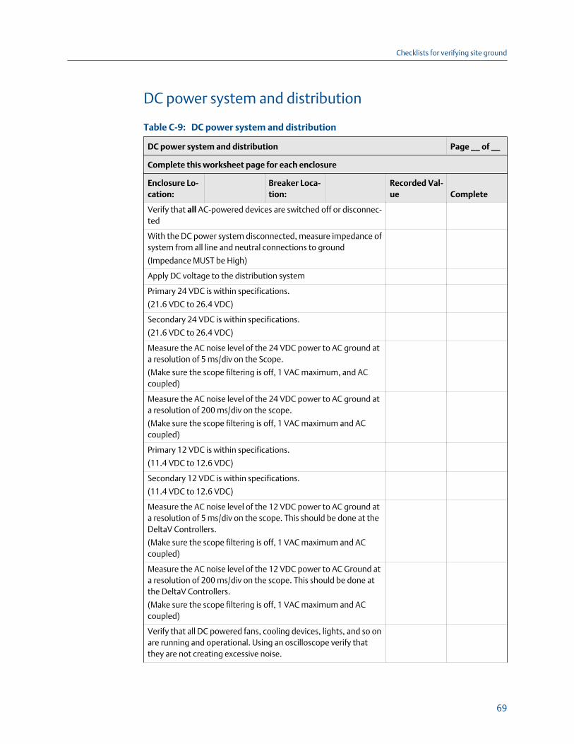
DC power system and distribution
DC power system and distributionTable C-9:
DC power system and distribution Page __ of __
Complete this worksheet page for each enclosure
Enclosure Lo-cation:
Breaker Loca-tion:
Recorded Val-ue Complete
Verify that all AC-powered devices are switched off or disconnec-ted
With the DC power system disconnected, measure impedance ofsystem from all line and neutral connections to ground
(Impedance MUST be High)
Apply DC voltage to the distribution system
Primary 24 VDC is within specifications.
(21.6 VDC to 26.4 VDC)
Secondary 24 VDC is within specifications.
(21.6 VDC to 26.4 VDC)
Measure the AC noise level of the 24 VDC power to AC ground ata resolution of 5 ms/div on the Scope.
(Make sure the scope filtering is off, 1 VAC maximum, and ACcoupled)
Measure the AC noise level of the 24 VDC power to AC ground ata resolution of 200 ms/div on the scope.
(Make sure the scope filtering is off, 1 VAC maximum and ACcoupled)
Primary 12 VDC is within specifications.
(11.4 VDC to 12.6 VDC)
Secondary 12 VDC is within specifications.
(11.4 VDC to 12.6 VDC)
Measure the AC noise level of the 12 VDC power to AC ground ata resolution of 5 ms/div on the scope. This should be done at theDeltaV Controllers.
(Make sure the scope filtering is off, 1 VAC maximum and ACcoupled)
Measure the AC noise level of the 12 VDC power to AC Ground ata resolution of 200 ms/div on the scope. This should be done atthe DeltaV Controllers.
(Make sure the scope filtering is off, 1 VAC maximum and ACcoupled)
Verify that all DC powered fans, cooling devices, lights, and so onare running and operational. Using an oscilloscope verify thatthey are not creating excessive noise.
Checklists for verifying site ground
69

DC power system and distribution (continued)Table C-9:
DC power system and distribution Page __ of __
Complete this worksheet page for each enclosure
Enclosure Lo-cation:
Breaker Loca-tion:
Recorded Val-ue Complete
Verify that LEDs of all DC powered devices indicate normal
Comments:
Checklists for verifying site ground
70

DeltaV controllers
DeltaV controllersTable C-10:
DeltaV controllers Page __ of __
Complete this worksheet page for each controller
Enclosure loca-tion:
Controllername:
Value/Com-ment Complete
Assembly:• Back planes plugged in tightly• All power supplies controllers, I/O modules screwed
in securely (Do not over torque)• Input power wiring termination tight and labeled• Network cables locked in place• Environmental conditions within specifications
System power supply LEDs normal
(Power-ON, Error-OFF)
Active controller's LEDs normal
(Power - ON, Error - OFF if downloaded / Flash if un-con-figured, Active - ON, Standby - OFF, CN1 - Flash if com-municating on the primary control network, CN2 - Flashif communicating on the secondary control network)
Standby controller's LEDs normal
(Power - ON, Error - OFF if downloaded / Flash if un-con-figured, Active - OFF, Standby - ON, CN1 - Flash if com-municating on the primary control network, CN2 - Flashif communicating on the secondary control network)
Controller accessible through standard diagnostics
(accessible, primary & secondary communication with-out increasing errors)
All I/O cards accessible through standard diagnostics
(accessible, no mismatches, no missing cards)
Are the network components used and the network in-stallation as per design?
Yes / No / N.A. By: ______________
Date: __________
Are all added cables certified for the application (for ex-ample CAT5 and fiber optic), properly terminated, la-beled and color-coded?
Yes / No / N.A. By: ______________
Date: __________
Are network cables routed and installed according tothe guidelines in the document Site Preparation and De-sign for DeltaV Digital Automation Systems?
Yes / No / N.A. By: ______________
Date: __________
Checklists for verifying site ground
71

DeltaV controllers (continued)Table C-10:
DeltaV controllers Page __ of __
Complete this worksheet page for each controller
Enclosure loca-tion:
Controllername:
Value/Com-ment Complete
Comments:
Checklists for verifying site ground
72

List of equipment used
List of equipment usedTable C-11:
List of equipment used Page __ of __
Manufacturer Type: Serial number:Re-calibrationdate: Used in section
Comments:
Checklists for verifying site ground
73

Checklists for verifying site ground
74

Appendix DReferences
General reference
Joffe, Elya B. and Lock, Kai-Sang, Grounds for Grounding: A Circuit-to-System Handbook, IEEEWiley & Sons, 2010.
Ott, Henry, Electromagnetic Compatibility Engineering, Wiley & Sons, 2009.
Vijayaraghavan, G., Brown, Mark, and Barnes, Malcolm, Practical Grounding, Bounding,Shielding and Surge Protection, Elsevier, 2004.
Power transmission reference
Electrical Transmission and Distribution Reference Book, Westinghouse, 1950.
Reference books for personnel and property safety
Soares Book on Grounding and Bonding, 10th Edition, International Association of ElectricalInspectors, 2008.
National Electric Code (NEC) 2011 Handbook, NFPA 70, 2011.
BS 7671:2008 Requirements for Electrical Installations 17th Edition, IET Wiring Regulations,2008.
Cook, Paul, Commentary on IET Wiring Regulations 17th Edition BS 7671:2008 Requirementsfor Electrical Installations, Institute of Engineering and Technology, 2008.
American standards
ANSI/ISA-RP12.06.01-2003, Recommended Practice for Wiring Methods for Hazardous(Classified) Locations Instrumentation Part 1: Intrinsic Safety.
ANSI/ISA-TR12.06.01-1999, Electrical Equipment in a Class 1, Division 2/Zone 2 HazardousLocation .
ANSI/ISA-84.01-2004, Application of Safety Instrumented Systems for the ProcessIndustries.
ANSI-J-STD-607-A-2002, Commercial Building Grounding (Earthing) and BondingRequirements for Telecommunications.
ATIS-0600333.2007, Grounding and Bonding of Telecommunications Equipment.
NFPA 780, Standard for the Installation of Lightning Protection Systems.
IEEE standards
IEEE Standard 1100-2005, Recommended Practice for Power and Grounding ElectronicEquipment (Emerald book).
References
75

IEEE Standard 142-2007, Recommended Practices for Grounding of Industrial andCommercial Power Systems (Green book).
IEEE Standard 493-2007, Recommended Practice for the Design of Reliable Industrial andCommercial Power Systems (Gold book).
IEEE Standard 1159-1995(R2001), Recommended Practice for Monitoring Electric PowerQuality.
IEEE Standard 519-1992, Recommended Practice and Requirements for Harmonic Controlin Electrical Power Systems.
IEEE Standard 1050 2004, Guide for Instrumentation and Control Equipment Grounding inGenerating Stations.
IEEE Standard 81-1983, Guide for Measuring Earth Resistivity, Ground Impedance, andEarth Surface Potentials of a Ground System.
IEEE Standard 45-2002, Recommended Practice for Electrical Installation on Shipboard.
IEEE 518-1982(1), Guide for the Installation of Electrical Equipment to Minimize NoiseInputs to Controllers from External Sources, (not currently supported by IEEE).
US Military Handbook
MIL-HDBK-419A, Grounding, Bonding, and Shielding for Electronic Equipments andFacilities (Vol. 1 Basic Theory; Vol. 2 Applications), 1987.
European international standards
IEC 60204-1,Ed. 5.1 2009, Safety of Machinery -Electrical equipment of Machines - Part 1:General Requirements
IEC 60364-4-44, Ed. 2.0 2007, Low-voltage Electrical Installations; Part 4-44: Protection forsafety - Protection against voltage disturbances and electromagnetic disturbances.
IEC 61140, Ed. 3.1 2009, Protection Against Electric Shock - Common Aspects forInstallation and Equipment.
IEC 61326-1 2005, Electrical Equipment For Measurement, Control and Laboratory Use -EMC Requirements.
IEC 61511-1 Ed. 1.0 2003, Functional safety - Safety instrumented systems for the processindustry sector - Part 1: Framework, definitions, system, hardware and softwarerequirements.
EN 61000-3-11 Ed. 1.0, Electromagnetic compatibility (EMC) - Part 3-11: Limits - Limitationof voltage changes, voltage fluctuations and flicker in public low-voltage supply systems -Equipment with rated current ≤ 75 A and subject to conditional connection.
EN 61000-3-12 Ed. 1.0, Electromagnetic compatibility (EMC) - Part 3-12: Limits - Limits forharmonic currents produced by equipment connected to public low-voltage systems withinput current > 16 A and ≤ 75 A per phase.
References
76

Lightning references
NFPA 780, Standard for the Installation of Lightning Protection Systems, 2011.
NUREG/CR-6866 ORNL/TM-2001/140, Technical Basis for Regulatory Guidance onLightning Protection in Nuclear Power Plants, 2011.
Lightning Protection for Engineers, National Lightning Safety Institute, 2009.
References
77

References
78