Embed Size (px)
Citation preview

Potential performance of environmental friendly
application of ORC and Flash technology in
geothermal power plants
Davide Bonalumi, Paola A. Bombarda, Costante M. Invernizzi
www.gecos.polimi.it

Davide Bonalumi
INTRODUCTION
Context
• Geothermal power plants temperature range of 150-200°C
Objective
• Definition and simulation of environmental friendly geothermal
plants evaluating the performances
• Effect of concentration of the CO2 on the performances of the
two scheme of plants
Methodology
• Bibliographic review for experimental data for validation of the
thermodynamic model for the geothermal fluid
• Aspen Plus simulations of the geothermal plants
Davide Bonalumi
Overview on geothermal fluids
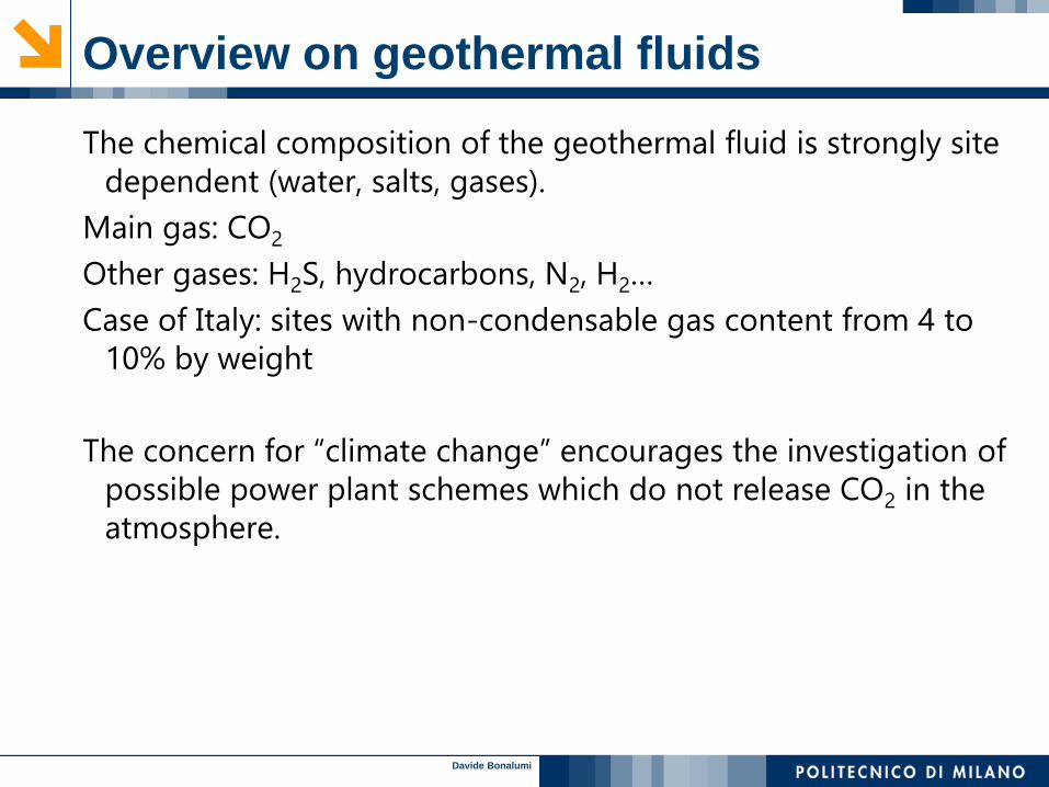
The chemical composition of the geothermal fluid is strongly site
dependent (water, salts, gases).
Main gas: CO2
Other gases: H2S, hydrocarbons, N2, H2…
Case of Italy: sites with non-condensable gas content from 4 to
10% by weight
The concern for “climate change” encourages the investigation of
possible power plant schemes which do not release CO2 in the
atmosphere.

Davide Bonalumi
Main technologies – binary systems
Geothermal fluid 100 °C- 160 °C (and higher)
advantage, geothermal fluid in a closed loop
Common configuration of binary cycle technology is equipped
with submersible pump that can guarantee a stable well
production, but that is subjected to scaling, cavitation that
determine a short lifespan.
Prod Well
Reinjection Well
Pump
Pump
Cooling Tower
Turbine

Davide Bonalumi
Turbine
water
Main technologies – flash systems
Geothermal fluid > 160 °C
In the traditional flash plant layout non-condensable gases are
extracted from the condenser,
The main feature of this technology is the adoption of a direct
cycle, whereby the geothermal fluid coming from wellhead is
flashed, and separated steam enters a steam turbine, followed by
a condenser.
The gas collected at the condeser are at low pressure: they are
recompressed at higher pressure
Cooling Tower
Reinjection
Production well

Davide Bonalumi
Thermodynamic properties of the geothermal fluid
This work focusses on the CO2 issue, and therefore only the
carbon dioxide is considered as non-condensable gas present in
the geothermal fluid.
The thermodynamic model adopted to study the performances
of the plants is validated with experimental results available in
literature.
The thermodynamic model that better performs is the Electrolyte-
NRTL, it considers the carbonic chemical equilibrium.
0
10
20
30
40
50
60
70
80
90
0 2 4 6 8 10
CO
2 m
ole
fra
c, %
Pressure, MPa
433.15 K
453.15 K
473.15 K
Model

Davide Bonalumi
Simulation of the Reservoir
The well-reservoir flow is simulated considering a horizontal mass
flow in a porous medium, followed by a vertical flow in a pipe,
under steady conditions.
Pressure difference between an undisturbed point in the
reservoir and the well feed is expressed by
The correlations of Beggs-Brill good results, it is quite largely
adopted in geothermal applications.
m
pCD
Parameter
Drawdown coefficient CD 0.4 bar/kg∙s
Reservoir pressure pres 100 bar
Well depth L 1000 m
Well diameter D 0,339 m

Davide Bonalumi
Simulation of zero emix Flash Plant
RES
WELL
FL1
FL2
CP1
TRB
MX
HX1
CND
PMP1
PMP2
DEM
WREINJ
PMP
MX1
SEP
CP2
S0
S2
S3
S7
S4
S8
S10
S11
S15
S16 S17
S22
S19
S5
S6
S24
S23
S12
S21
S18
S9
S20
Flash power plant
Description of the component
CMP compressor
CND condenser
DEM demister
FL flash
HX heat exchanger
MX mixer
PMP pump
RES reservoir
SEP separator
TRB turbine
WELL well
CO2 recovery
Production well
Reinjection well
Davide Bonalumi
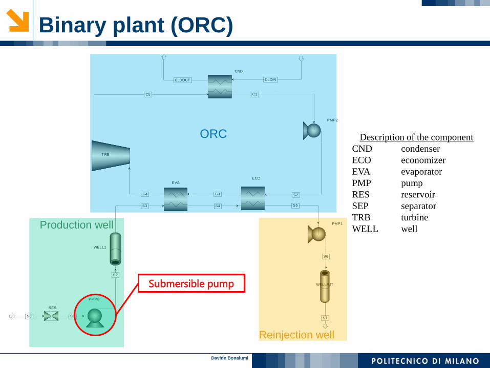
RES
WELL1
WELLRJT
PMP1
TRB
CND
PMP2
EVA
ECO
PMP0
S0 S1S7
S6
C5 C1
CLDINCLDOUT
S3 S4
C4 C3 C2
S5
S2
Binary plant (ORC)
ORC Description of the component
CND condenser
ECO economizer
EVA evaporator
PMP pump
RES reservoir
SEP separator
TRB turbine
WELL well Production well
Reinjection well
Submersible pump

Davide Bonalumi
Organic Fluids
n-Pentane (flammable fluid).
TCr: 196.5 °C; PCr: 33.7 bar MW: 72.2 g/mol
HCFO-1233zd(E) trans-1-chloro-3,3,3-trifluoropropene
TCr: 165.6 °C; PCr: 35.7 bar MW: 130.5 g/mol
It is environmentally friendly: GWP = 5; non-flammable.
According to preliminary investigation, it seems thermally stable at least
up to nearly 200 °C.
Davide Bonalumi
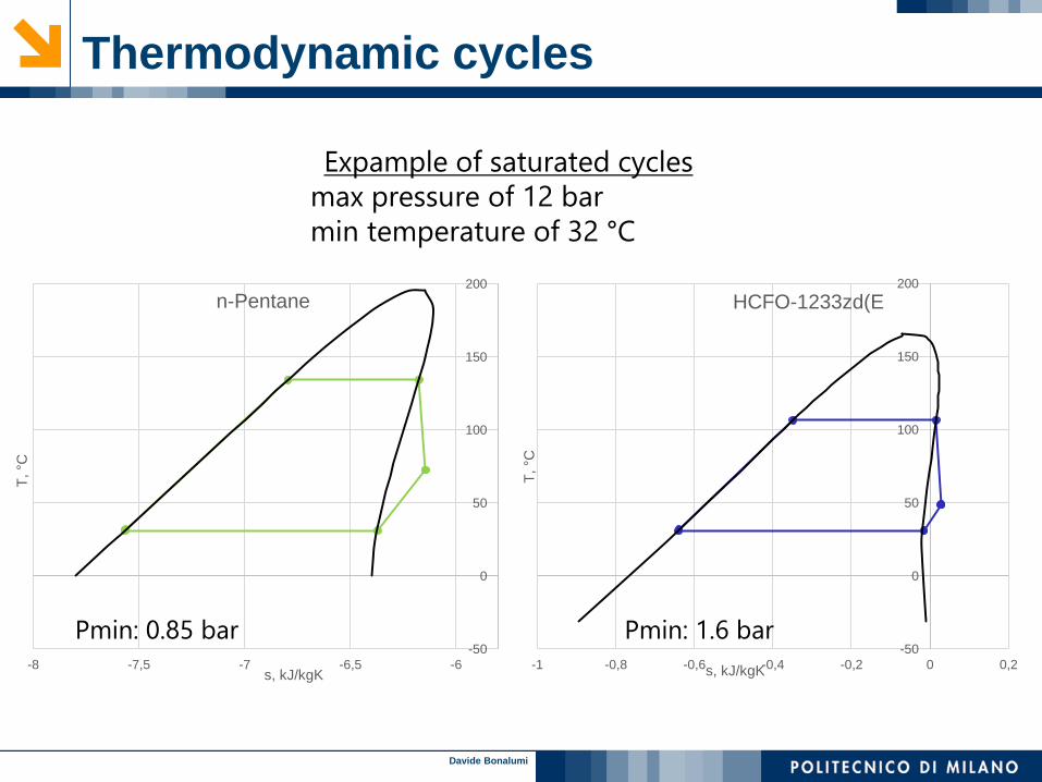
Thermodynamic cycles
-50
0
50
100
150
200
-8 -7,5 -7 -6,5 -6
T, °C
s, kJ/kgK
n-Pentane
-50
0
50
100
150
200
-1 -0,8 -0,6 -0,4 -0,2 0 0,2
T, °C
s, kJ/kgK
HCFO-1233zd(E
Expample of saturated cycles
max pressure of 12 bar
min temperature of 32 °C
Pmin: 1.6 bar Pmin: 0.85 bar
Davide Bonalumi
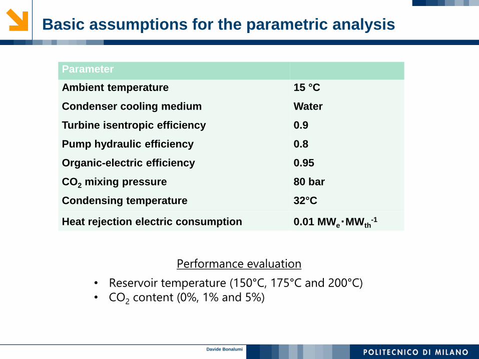
Basic assumptions for the parametric analysis
Parameter
Ambient temperature 15 °C
Condenser cooling medium Water
Turbine isentropic efficiency 0.9
Pump hydraulic efficiency 0.8
Organic-electric efficiency 0.95
CO2 mixing pressure 80 bar
Condensing temperature 32°C
Heat rejection electric consumption 0.01 MWe‧MWth-1
Performance evaluation
• Reservoir temperature (150°C, 175°C and 200°C)
• CO2 content (0%, 1% and 5%)

Davide Bonalumi
Results Flash plant with CO2 recovery
Mass flow rate (productivity of the well)
Pressure drop at “pre-flash”: 1%
A parametric analysis
Pressure at the flash chamber before the turbine
200 °C
CO2 conc. 0% 1% 5%
𝒑𝑾𝒉, bar 2.3 9.2 15.9
𝒎 𝑾, kg/s 93 80 105
Paux, MWe 0.74 5.4 2.6
Qcond, MWth 33.5 16.4 23.3
NetP, MWe 4.9 2.0 2.6

Davide Bonalumi
Results Binary plants
HCFO1233zd(E) n-Pentane
CO2 conc. 0% 1% 0% 1%
𝒎 𝑶𝑹𝑪, kg/s 547 488 220 210
Tmax ORC, °C 153 153 130 130
Pmax ORC, bar 29 29 11 11
Qcond, MWth 112 104 95.4 91.1
NetP, MWe 21.6 19.3 16.5 15.7
200 °C
Mass flow rate (max of pump: 200 l/s)
ΔTmin at heat exchangers: 10 °C
A parametric analysis
Pressure of the cycle maximization of power production
CO2 concentration: not possible exceed 1% because of cavitation

Davide Bonalumi
Comparisons of results
0
2
4
6
150 °C 175 °C 200°C
Ne
t P
ow
er,
MW
Flash plant
0% 1% 5%
0
10
20
30
150 °C 175 °C 200 °C
Ne
t P
ow
er,
MW
ORC plant, 0%
HCFO-1233zd(E)n-pentane
Organic Rankine Cycle reach higher values, but the CO2 content is a
limitation in case of use of a pump in the well

Davide Bonalumi
Conclusions and future works
Conclusions
The performance of investigated layout are highly affected by the
concentration of the carbon dioxide present in the reservoir. In general:
Submersible pump has good effect on power production
Presence of CO2 decrease the power production
Flash plants can handle wide range of CO2 concentration
HCFO-1233zd(E) is a possible option for geothermal application
Future works
• Presence of salts in geothermal fluid
• Flash: recovery of heat duty of the CO2 compression; separated
reinjection of CO2; 2 pressures level.
• ORC: other scheme of plants (2 pressure levels)
• Techno-economic analysis


![Prediction of pressure drop in multiphase horizontal pipe flow · PDF fileCleveland[5]and Beggs Brill[6]two phase correlations and found that they over predicted Sl and Fr flow and](https://img.dokumen.tips/doc/110x75/5ab441047f8b9a6e1c8ba02e/prediction-of-pressure-drop-in-multiphase-horizontal-pipe-flow-5and-beggs-brill6two.jpg)


![arXiv:1905.09746v1 [physics.data-an] 23 May 2019 · Among the most widely used are Aziz and Govier [9], Beggs & Brill [10], Mukherjee & Brill [11], and others. Many articles are concerned](https://img.dokumen.tips/doc/110x75/5f89205809be2356907fd0c7/arxiv190509746v1-23-may-2019-among-the-most-widely-used-are-aziz-and-govier.jpg)


![[Brill J.P., Beggs H.D.] Two-Phase Flow in Pipes](https://img.dokumen.tips/doc/110x75/577c7f931a28abe054a52c88/brill-jp-beggs-hd-two-phase-flow-in-pipes.jpg)

