Embed Size (px)
Citation preview

Potable Water Distribution System
Design Criteria and Standards
Lucerne, ColoradoFINAL - APRIL 12, 2018

(THIS PAGE INTENTIONALLY LEFT BLANK)

NORTH WELD COUNTY WATER DISTRICT NORTH WELD COUNTY WATER DISTRICTFINAL – 07/24/2019 DESIGN CRITERIA AND STANDARDSADDENDUM 01: DESIGN CRITERIA AND STANDARDS PAGE 1 OF 4
NORTH WELD COUNTY WATER DISTRICT
DESIGN CRITERIA AND STANDARDS
ADDENDUM NO. 01EFFECTIVE JULY 24, 2019
1. Part 1 (Design Criteria) – Section 2 (2.01.A.5): Delete the Acceptance Block in its entirety, and replace with the following:
CONSTRUCTION MUST BE IN ACCORDANCE WITH APPLICABLE NWCWD DESIGN CRITERIA AND STANDARDS AND THE CONSTRUCTION PLANS
APPROVED BY NWCWD. NWCWD’S ACCEPTANCE OF CONSTRUCTION PLANS SHALL BE VALID FOR A PERIOD OF ONE YEAR FOLLOWING THE DATE OF ITS
APPROVAL BELOW. NWCWD’S ACCEPTANCE SHALL NOT RELIEVE OWNER OR ITS ENGINEER FROM LIABILITY FOR ERRORS, OMISSIONS, OR DESIGN
DEFICIENCIES AND OWNER AND ITS ENGINEERS SHALL HOLD NWCWD HARMLESS FROM SUCH LIABILITY.
ACCEPTED BY___________________________ ________________
(DISTRICT ENGINEER) (DATE)
2. Part 1 (Design Criteria) – Section 3 (3.02.B.2): Delete subparagraph 3.02.B.2 in its entirety, and replace with the following:
2. Potable water transmission mains are sixteen-inches (16”) and larger in diameter.
3. Part 1 (Design Criteria) – Section 3 (3.02.B.2.a): Delete subparagraph 3.02.B.2.a in its entirety, and replace with the following:
a. In some cases, pipes smaller than sixteen-inches (16”) may be classified as transmission mains.
4. Part 1 (Design Criteria) – Section 3 (Table 3-2): Delete the title of Table 3-2 in its entirety, and replace with the following:
Table 3-2: Potable Water Design Flow –Urban Commercial –
Per 1,000 Sq. Ft. of Building Space
NORTH WELD COUNTY WATER DISTRICT NORTH WELD COUNTY WATER DISTRICTFINAL – 07/24/2019 DESIGN CRITERIA AND STANDARDSADDENDUM 01: DESIGN CRITERIA AND STANDARDS PAGE 2 OF 4
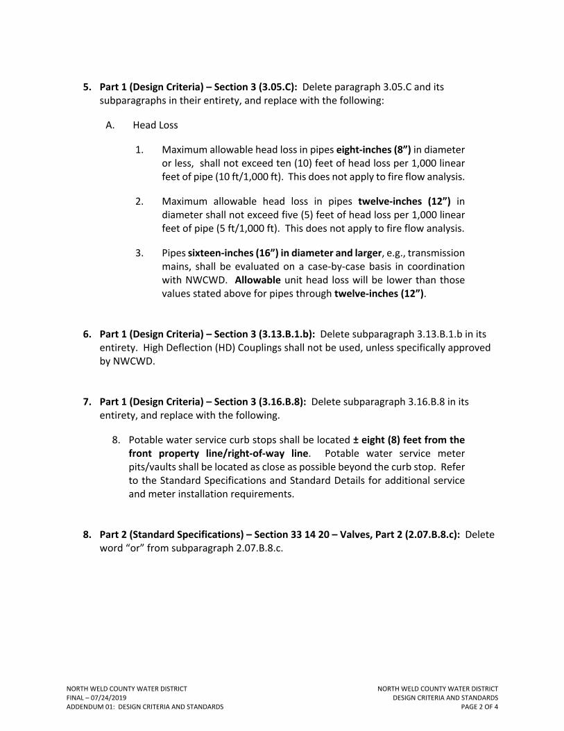
5. Part 1 (Design Criteria) – Section 3 (3.05.C): Delete paragraph 3.05.C and its subparagraphs in their entirety, and replace with the following:
A. Head Loss
1. Maximum allowable head loss in pipes eight-inches (8”) in diameter or less, shall not exceed ten (10) feet of head loss per 1,000 linear feet of pipe (10 ft/1,000 ft). This does not apply to fire flow analysis.
2. Maximum allowable head loss in pipes twelve-inches (12”) in diameter shall not exceed five (5) feet of head loss per 1,000 linear feet of pipe (5 ft/1,000 ft). This does not apply to fire flow analysis.
3. Pipes sixteen-inches (16”) in diameter and larger, e.g., transmission mains, shall be evaluated on a case-by-case basis in coordination with NWCWD. Allowable unit head loss will be lower than those values stated above for pipes through twelve-inches (12”).
6. Part 1 (Design Criteria) – Section 3 (3.13.B.1.b): Delete subparagraph 3.13.B.1.b in its entirety. High Deflection (HD) Couplings shall not be used, unless specifically approved by NWCWD.
7. Part 1 (Design Criteria) – Section 3 (3.16.B.8): Delete subparagraph 3.16.B.8 in its entirety, and replace with the following.
8. Potable water service curb stops shall be located ± eight (8) feet from the front property line/right-of-way line. Potable water service meter pits/vaults shall be located as close as possible beyond the curb stop. Refer to the Standard Specifications and Standard Details for additional service and meter installation requirements.
8. Part 2 (Standard Specifications) – Section 33 14 20 – Valves, Part 2 (2.07.B.8.c): Delete word “or” from subparagraph 2.07.B.8.c.
NORTH WELD COUNTY WATER DISTRICT NORTH WELD COUNTY WATER DISTRICTFINAL – 07/24/2019 DESIGN CRITERIA AND STANDARDSADDENDUM 01: DESIGN CRITERIA AND STANDARDS PAGE 3 OF 4
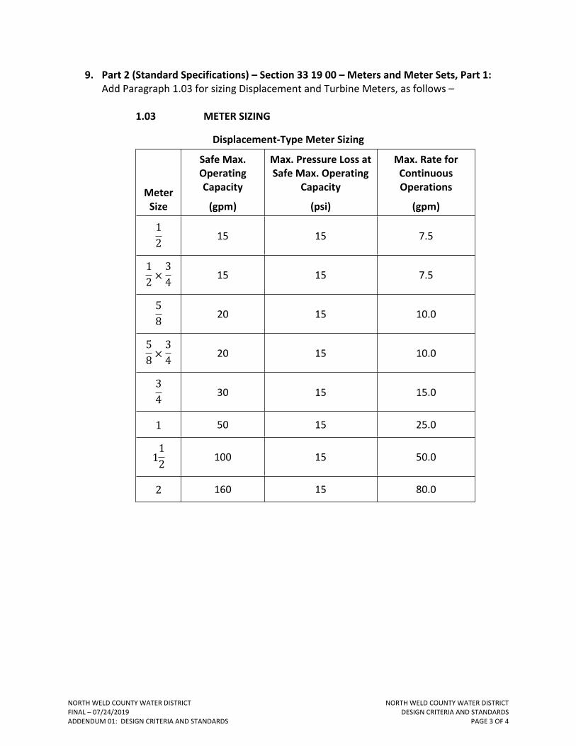
9. Part 2 (Standard Specifications) – Section 33 19 00 – Meters and Meter Sets, Part 1: Add Paragraph 1.03 for sizing Displacement and Turbine Meters, as follows –
1.03 METER SIZING
Displacement-Type Meter Sizing
Meter Size
Safe Max. Operating Capacity
(gpm)
Max. Pressure Loss at Safe Max. Operating
Capacity
(psi)
Max. Rate for Continuous Operations
(gpm)
12 15 15 7.5
12 ×
34 15 15 7.5
58 20 15 10.0
58 ×
34 20 15 10.0
34 30 15 15.0
1 50 15 25.0
112 100 15 50.0
2 160 15 80.0

NORTH WELD COUNTY WATER DISTRICT NORTH WELD COUNTY WATER DISTRICTFINAL – 07/24/2019 DESIGN CRITERIA AND STANDARDSADDENDUM 01: DESIGN CRITERIA AND STANDARDS PAGE 4 OF 4
Turbine-Type Meter Sizing
Class/
TypeMeter
Size
Safe Max. Operating Capacity
(gpm)
Max. Pressure Loss at Safe
Max. Operating Capacity
(psi)
Max. Rate for Continuous Operations
(gpm)
34 30 15 20
1 50 15 35
112 100 15 65
Class I/
Vertical-Shaft Type
2 160 15 100
112 120 7 90Class II/
In-Line (High-
Velocity) Type
2 190 7 160
10. Part 3 (Standard Details) – Detail No. 3314181, WATER SERVICE LOCATION PLAN: Delete detail in its entirety, and replace with the attached detail – dated 04/02/2019.
11. Part 3 (Standard Details) – Detail No. 3314183, METER PIT CONSTRUCTION ENVELOPE: Delete detail in its entirety, and replace with the attached detail – dated 04/02/2019.
END OF ADDENDUM

W
W
W
W
W
W
W
W
W
W
M
M
LO
T LIN
E
5 FT
(TYP)
R.O.W. LINE
INTERIOR UTILITY
EASEMENT LINE
CURB STOP, INSTALLED PER
DETAIL NO. 3314182 AND NOTE 3
METER PIT SET BY
NWCWD, SEE NOTE 1
STREET
WATERLINE
SERVICE LINE,
SEE NOTE 2
S
ID
E
W
A
L
K
1. REFER TO DETAIL NO. 3314183 FOR "METER PIT CONSTRUCTION ENVELOPE".
2. REFER TO DETAIL NO. 3314182 FOR "1-INCH SERVICE ASSEMBLY".
3. CURB STOP SHALL BE PLACED APPROXIMATELY EIGHT (8) FEET FROM RIGHT-OF-WAY (R.O.W.)
LINE.
NOTES:
DETAIL NO:NORTH WELD COUNTYWATER DISTRICT
970-356-3020www.nwcwd.org
3314181
NORTH WELD
C
O
U
N
T
Y
W
A
TE
R
D
I
S
T
R
I
C
T
ESTABLISHED
1962
NWCWD APPD:
ORIG DATE:
REV DATE: 04/02/2019
04/12/2018
GM
WATER SERVICE LOCATION PLAN

4 F
T M
AX
4 FT WIDE x 8 FT LONG
METER PIT CONSTRUCTION
ENVELOPE
PROPOSED CURBSTOP
(TYPICAL NON-POTABLE)
PROPOSED METER PIT
EXISTING CURBSTOP
(ONLY IN SUBDIVISIONS)
EXISTING SERVICE
LINE FROM MAIN
SERVICE LINE TO CUSTOMER;
CONNECTION IS 1" FNPT
1. AT TIME OF METER PIT INSTALLATION, EXISTING GRADE MUST BE WITHIN 12" OF FINAL LOT GRADE. A
STAKE OR STRING LINE SHALL BE USED TO INDICATE FINAL GRADE SO METER PIT CAN BE SET TO
PROPER ELEVATION.
2. METER PIT CONSTRUCTION ENVELOPE SHALL NOT BE PLACED WITHIN A HARD SURFACE DRIVEWAY OR
SIDEWALK TO FACILITATE EASE OF MAINTENANCE.
3. ONLY GRASS, LANDSCAPE ROCK, OR BARK MAY COVER THE METER PIT CONSTRUCTION ENVELOPE. DO
NOT PLACE TREES, SHRUBS, BUSHES OR OTHER EXPENSIVE TO REPLACE LANDSCAPE OVER
CONSTRUCTION ENVELOPE.
NOTES:
CONNECTION TO CUSTOMER
SERVICE IS
3
4
" MNPT
DETAIL NO:NORTH WELD COUNTYWATER DISTRICT
970-356-3020www.nwcwd.org
3314183
NORTH WELD
C
O
U
N
T
Y
W
A
TE
R
D
I
S
T
R
I
C
T
ESTABLISHED
1962
NWCWD APPD:
ORIG DATE:
REV DATE: 04/02/2019
04/12/2018
GMMETER PIT CONSTRUCTION
ENVELOPE

DESIGN CRITERIA AND STANDARDS(INCLUDING STANDARD SPECIFICATIONS AND STANDARD DETAILS)
POTABLE WATER DISTRIBUTION SYSTEM
DESIGN CRITERIA PART 1STANDARD SPECIFICATIONS PART 2
STANDARD DETAILS PART 3
FINAL
APRIL 12, 2018
LUCERNE, COLORADO

(THIS PAGE INTENTIONALLY LEFT BLANK)

DESIGN CRITERIA AND STANDARDS
POTABLE WATER DISTRIBUTION SYSTEM
PART 1
DESIGN CRITERIA

(THIS PAGE INTENTIONALLY LEFT BLANK)

DESIGN CRITERIA AND STANDARDS
DESIGN CRITERIA
PAGE 1 OF 38
POTABLE WATER DISTRIBUTION SYSTEM DESIGN CRITERIA
TABLE OF CONTENTS
SECTION 1 - GENERAL REQUIREMENTS ............................................................................................2
1.01. SCOPE ........................................................................................................................................ 2
1.02. DEFINITIONS AND ABBREVIATIONS .......................................................................................... 2
1.03. MINIMUM STANDARDS ............................................................................................................ 6
1.04. RELATIONSHIP TO OTHER STANDARDS..................................................................................... 7
1.05. REVIEW AND ACCEPTANCE ....................................................................................................... 7
SECTION 2 - SUBMITTAL REQUIREMENTS ........................................................................................9
2.01. GENERAL ................................................................................................................................... 9
2.02. PRELIMINARY CONSTRUCTION PLAN REQUIREMENTS ........................................................... 10
2.03. FINAL CONSTRUCTION PLAN REQUIREMENTS ........................................................................ 11
2.04. FINAL PLAT AND REPLAT REQUIREMENTS .............................................................................. 13
2.05. LANDSCAPE PLANS REQUIREMENTS ....................................................................................... 14
2.06. EASEMENTS ............................................................................................................................. 14
2.07. HYDRAULIC REPORT – POTABLE WATER ................................................................................. 15
2.08. AS-CONSTRUCTED RECORD DRAWING REQUIREMENTS ........................................................ 21
2.09. REIMBURSEMENT FOR MAIN DESIGN AND INSTALLATION COSTS ......................................... 22
SECTION 3 - POTABLE WATER DISTRIBUTION SYSTEM DESIGN CRITERIA ......................................... 23
3.01. GENERAL ................................................................................................................................. 23
3.02. DEFINITIONS ............................................................................................................................ 23
3.03. DESIGN FLOW .......................................................................................................................... 24
3.04. PRESSURE REQUIREMENTS ..................................................................................................... 26
3.05. HYDRAULIC DESIGN ................................................................................................................. 27
3.06. POTABLE WATER MAIN SIZE ................................................................................................... 28
3.07. DEPTH OF BURY ....................................................................................................................... 28
3.08. CONNECTIONS TO THE EXISTING POTABLE WATER SYSTEM .................................................. 28
3.09. LOCATION AND LOOPING OF POTABLE WATER MAINS .......................................................... 28
3.10. POTABLE WATER SYSTEM PHASED INSTALLATION AND STUBOUTS ...................................... 29
3.11. PIPE MATERIAL ........................................................................................................................ 30
3.12. VALVES .................................................................................................................................... 30
3.13. CURVED PIPE ALIGNMENT ...................................................................................................... 32
3.14. THRUST RESTRAINT ................................................................................................................. 32
3.15. POTABLE WATER MAIN AND SERVICE ENCASEMENTS ........................................................... 33
3.16. POTABLE WATER SERVICES AND FIRE SPRINKLER LINES ......................................................... 34
3.17. POTABLE WATER MAINS AND SERVICES IN RELATION TO OTHER UTILITIES .......................... 36
3.18. FIRE PROTECTION AND HYDRANT SPACING ........................................................................... 37
3.19. CROSS CONNECTION AND BACKFLOW PREVENTION .............................................................. 37
NORTH WELD COUNTY WATER DISTRICTFINAL 04/12/2018PART 1: DESIGN CRITERIA

DESIGN CRITERIA AND STANDARDS
DESIGN CRITERIA
PAGE 2 OF 38
SECTION 1 - GENERAL REQUIREMENTS
1.01. SCOPE
A. The purpose of the Design Criteria (Criteria) is to present the minimum design and
technical criteria for the analysis and design of potable water distribution system for
which North Weld County Water District (NWCWD) acceptance is required. The Criteria
may be amended as new technology is developed or a need for revision is demonstrated
and proven through experience and use. The Design Engineer shall be responsible for
compliance with these Criteria as well as other applicable design and construction
standards in the preparation of engineering reports, construction drawings, and
specifications for NWCWD review and acceptance.
1.02. DEFINITIONS AND ABBREVIATIONS
A. Wherever the following words, phrases, and abbreviations appear in these
specifications, they shall have the following meaning:
Table 1-1: Definitions and Abbreviations
Acronym or
Abbreviation Definition
ac acre
ac-ft acre-feet
ANSI American National Standards Institute
APPROVED PLAN The latest revised Construction Drawing(s) accepted by NWCWD
APWA American Public Works Association
AS-CONSTRUCTED
DRAWINGS
Drawings reflecting actual conditions and information for the project
after construction is completed
ASME American Society of Mechanical Engineers
ASTM American Society for Testing Materials
AWWA American Water Works Association
CDOT Colorado Department of Transportation
CDPHE Colorado Department of Public Health and Environment
NORTH WELD COUNTY WATER DISTRICTFINAL 04/12/2018PART 1: DESIGN CRITERIA
DESIGN CRITERIA AND STANDARDS
DESIGN CRITERIA
PAGE 3 OF 38
Acronym or
Abbreviation Definition
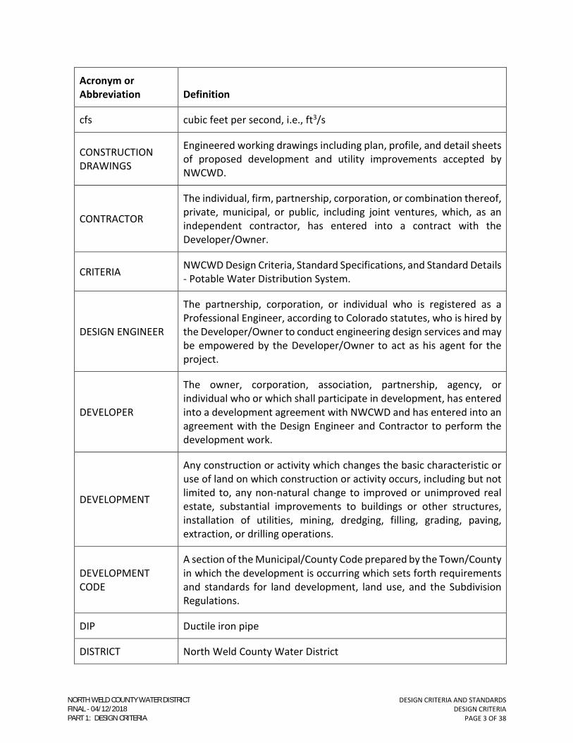
cfs cubic feet per second, i.e., ft3/s
CONSTRUCTION
DRAWINGS
Engineered working drawings including plan, profile, and detail sheets
of proposed development and utility improvements accepted by
NWCWD.
CONTRACTOR
The individual, firm, partnership, corporation, or combination thereof,
private, municipal, or public, including joint ventures, which, as an
independent contractor, has entered into a contract with the
Developer/Owner.
CRITERIA NWCWD Design Criteria, Standard Specifications, and Standard Details
- Potable Water Distribution System.
DESIGN ENGINEER
The partnership, corporation, or individual who is registered as a
Professional Engineer, according to Colorado statutes, who is hired by
the Developer/Owner to conduct engineering design services and may
be empowered by the Developer/Owner to act as his agent for the
project.
DEVELOPER
The owner, corporation, association, partnership, agency, or
individual who or which shall participate in development, has entered
into a development agreement with NWCWD and has entered into an
agreement with the Design Engineer and Contractor to perform the
development work.
DEVELOPMENT
Any construction or activity which changes the basic characteristic or
use of land on which construction or activity occurs, including but not
limited to, any non-natural change to improved or unimproved real
estate, substantial improvements to buildings or other structures,
installation of utilities, mining, dredging, filling, grading, paving,
extraction, or drilling operations.
DEVELOPMENT
CODE
A section of the Municipal/County Code prepared by the Town/County
in which the development is occurring which sets forth requirements
and standards for land development, land use, and the Subdivision
Regulations.
DIP Ductile iron pipe
DISTRICT North Weld County Water District
NORTH WELD COUNTY WATER DISTRICTFINAL 04/12/2018PART 1: DESIGN CRITERIA

DESIGN CRITERIA AND STANDARDS
DESIGN CRITERIA
PAGE 4 OF 38
Acronym or
Abbreviation Definition
Domestic water use
Refers to all household and corresponding lot irrigation for single
family and applicable multifamily residential potable water use. It shall
also refer to all potable water use, including potable irrigation, for
commercial and industrial uses.
EASEMENT
Shall mean a right granted by the property owner permitting a
designated part or interest of the property to be used by others for
specific use or purpose.
EPA Environmental Protection Agency
ft2 square feet
ft/s feet per second
FIRE FLOW, FF
Shall be inclusive of fire hydrant and fire sprinkler flow, as required by
the governing fire protection agency. Residential, commercial, or
industrial developments requiring fire sprinkler systems shall have fire
sprinkler demands, in addition to hydrant fire flows, placed in the
hydraulic water model at appropriate node locations.
GEOTECHNICAL
ENGINEER
A partnership, corporation, or individual who is registered as a
Professional Engineer, according to Colorado statutes, proficient in the
area of soil mechanics, and who is hired by the Developer/Owner to
conduct subsurface soils investigations and evaluations, ground water
assessments, and other related engineering services.
gpcd gallons per capita per day
gpd gallons per day
gpm gallons per minute
HP horsepower
INSPECTOR Representative of NWCWD designated to conduct construction/field
observation.
LAND SURVEYOR
A registered Professional Land Surveyor, according to State of
Colorado statutes, who is hired by the Developer/Owner to determine
the boundaries and elevations of land and/or structures and other
related surveying services.
NORTH WELD COUNTY WATER DISTRICTFINAL 04/12/2018PART 1: DESIGN CRITERIA

DESIGN CRITERIA AND STANDARDS
DESIGN CRITERIA
PAGE 5 OF 38
Acronym or
Abbreviation Definition
MAY A permissive condition. Where the word “may” is used, no
requirement for design or application is intended.
MDD Maximum Day Demand
NEC National Electric Code
NWCWD North Weld County Water District
OSHA Occupational Safety and Health Administration
OWNER Any person having title or right of ownership in the surface estate of
real property or leasehold interest within.
PHD Peak Hour Demand
PLANS See CONSTRUCTION DRAWINGS
PLC Programmable Logic Controller.
PROFESSIONAL
ENGINEER
An engineer registered with the State of Colorado according to State
of Colorado statutes.
PROFESSIONAL
LAND SURVEYOR
A land surveyor registered with the State of Colorado according to
State of Colorado statutes.
psi pounds per square inch
PUD Planned Unit Development
PVC Polyvinyl chloride
SHALL
A mandatory condition. Where certain requirements in the design or
application are described with the “shall” stipulation, it is mandatory
that these requirements be met.
SHOULD
An advisory condition. Where the word “should” is used, it is
considered to be advisable usage, but not mandatory. Deviations may
be allowed when reasons are given which show that the intent of the
standard is met.
NORTH WELD COUNTY WATER DISTRICTFINAL 04/12/2018PART 1: DESIGN CRITERIA
DESIGN CRITERIA AND STANDARDS
DESIGN CRITERIA
PAGE 6 OF 38
Acronym or
Abbreviation Definition
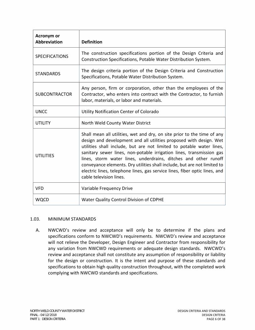
SPECIFICATIONS The construction specifications portion of the Design Criteria and
Construction Specifications, Potable Water Distribution System.
STANDARDS The design criteria portion of the Design Criteria and Construction
Specifications, Potable Water Distribution System.
SUBCONTRACTOR
Any person, firm or corporation, other than the employees of the
Contractor, who enters into contract with the Contractor, to furnish
labor, materials, or labor and materials.
UNCC Utility Notification Center of Colorado
UTILITY North Weld County Water District
UTILITIES
Shall mean all utilities, wet and dry, on site prior to the time of any
design and development and all utilities proposed with design. Wet
utilities shall include, but are not limited to potable water lines,
sanitary sewer lines, non-potable irrigation lines, transmission gas
lines, storm water lines, underdrains, ditches and other runoff
conveyance elements. Dry utilities shall include, but are not limited to
electric lines, telephone lines, gas service lines, fiber optic lines, and
cable television lines.
VFD Variable Frequency Drive
WQCD Water Quality Control Division of CDPHE
1.03. MINIMUM STANDARDS
A. NWCWD’s review and acceptance will only be to determine if the plans and
specifications conform to NWCWD’s requirements. NWCWD’s review and acceptance
will not relieve the Developer, Design Engineer and Contractor from responsibility for
any variation from NWCWD requirements or adequate design standards. NWCWD’s
review and acceptance shall not constitute any assumption of responsibility or liability
for the design or construction. It is the intent and purpose of these standards and
specifications to obtain high quality construction throughout, with the completed work
complying with NWCWD standards and specifications.
NORTH WELD COUNTY WATER DISTRICTFINAL 04/12/2018PART 1: DESIGN CRITERIA
DESIGN CRITERIA AND STANDARDS
DESIGN CRITERIA
PAGE 7 OF 38
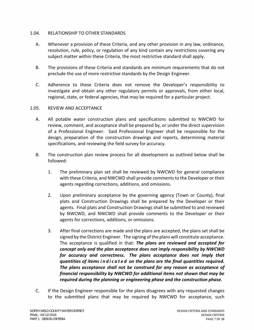
1.04. RELATIONSHIP TO OTHER STANDARDS
A. Whenever a provision of these Criteria, and any other provision in any law, ordinance,
resolution, rule, policy, or regulation of any kind contain any restrictions covering any
subject matter within these Criteria, the most restrictive standard shall apply.
B. The provisions of these Criteria and standards are minimum requirements that do not
preclude the use of more restrictive standards by the Design Engineer.
C. Adherence to these Criteria does not remove the Developer’s responsibility to
investigate and obtain any other regulatory permits or approvals, from either local,
regional, state, or federal agencies, that may be required for a particular project.
1.05. REVIEW AND ACCEPTANCE
A. All potable water construction plans and specifications submitted to NWCWD for
review, comment, and acceptance shall be prepared by, or under the direct supervision
of a Professional Engineer. Said Professional Engineer shall be responsible for the
design, preparation of the construction drawings and reports, determining material
specifications, and reviewing the field survey for accuracy.
B. The construction plan review process for all development as outlined below shall be
followed:
1. The preliminary plan set shall be reviewed by NWCWD for general compliance
with these Criteria, and NWCWD shall provide comments to the Developer or their
agents regarding corrections, additions, and omissions.
2. Upon preliminary acceptance by the governing agency (Town or County), final
plats and Construction Drawings shall be prepared by the Developer or their
agents. Final plats and Construction Drawings shall be submitted to and reviewed
by NWCWD, and NWCWD shall provide comments to the Developer or their
agents for corrections, additions, or omissions.
3. After final corrections are made and the plans are accepted, the plans set shall be
signed by the District Engineer. The signing of the plans will constitute acceptance.
The acceptance is qualified in that: The plans are reviewed and accepted for
concept only and the plan acceptance does not imply responsibility by NWCWD
for accuracy and correctness. The plans acceptance does not imply that
quantities of items i n d i c a t e d on the plans are the final quantities required.
The plans acceptance shall not be construed for any reason as acceptance of
financial responsibility by NWCWD for additional items not shown that may be
required during the planning or engineering phase and the construction phase.
C. If the Design Engineer responsible for the plans disagrees with any requested changes
to the submitted plans that may be required by NWCWD for acceptance, such
NORTH WELD COUNTY WATER DISTRICTFINAL 04/12/2018PART 1: DESIGN CRITERIA

DESIGN CRITERIA AND STANDARDS
DESIGN CRITERIA
PAGE 8 OF 38
disagreement shall be brought to the attention of NWCWD, and if required by NWCWD,
in writing.
D. The Seal of the Design Engineer on plans so corrected and accepted for construction will
signify that the Professional Engineer has reviewed, approved, and authorized said
corrected plans for construction.
E. No construction shall be undertaken without a NWCWD-accepted and signed set of
Construction Drawings and a recorded plat or required potable water easements and
appropriate water service agreements.
NORTH WELD COUNTY WATER DISTRICTFINAL 04/12/2018PART 1: DESIGN CRITERIA

DESIGN CRITERIA AND STANDARDS
DESIGN CRITERIA
PAGE 9 OF 38
SECTION 2 - SUBMITTAL REQUIREMENTS
2.01. GENERAL
A. Requirements discussed in this section are the minimum for potable water distribution
system and are not meant to be all-inclusive. Other requirements may be needed for a
complete design. The Design Engineer shall consider the maintenance and operational
aspects of the potable water distribution and system infrastructure, as well as,
constructability in their design.
1. NWCWD shall be contacted at the beginning of the project planning stages to
determine if raw water requirements need to be met prior to Construction
Drawing acceptance. Contact NWCWD at 970-356-3020 to discuss raw water
requirements.
2. All construction drawings shall be legible and submitted on either 24” x 36” or 22”
x 34” sheets.
3. A legend describing all line types, symbols, and abbreviations shall be shown
either on the cover sheet or each individual sheet.
4. Each sheet in the Construction Drawings shall be marked “PRELIMINARY, NOT FOR
CONSTRUCTION” with the date of submittal. This statement will be removed on
the final NWCWD-accepted Construction Drawings.
5. All sheets pertaining to potable water distribution system (including but not
limited to the title sheet, utility plan, conduit plan, plan and profile sheets, notes
and details sheets, and landscaping plans) shall contain an acceptance block for
the District Engineer’s acceptance, which shall appear as follows:
CONSTRUCTION MUST BE IN ACCORDANCE WITH APPLICABLE NWCWD
DESIGN CRITERIA AND STANDARDS. NWCWD’S ACCEPTANCE ALLOWS FOR
PLAN DISTRIBUTION. NWCWD’S ACCEPTANCE SHALL NOT RELIEVE THE
DESIGN ENGINEER’S RESPONSIBILITY FOR ERRORS, OMISSIONS, OR DESIGN
DEFICIENCIES FOR WHICH NWCWD IS HELD HARMLESS.
ACCEPTED BY___________________________ ________________
(DISTRICT ENGINEER) (DATE)
6. NWCWD-accepted and signed construction plans are required prior to the
commencement of construction.
NORTH WELD COUNTY WATER DISTRICTFINAL 04/12/2018PART 1: DESIGN CRITERIA

DESIGN CRITERIA AND STANDARDS
DESIGN CRITERIA
PAGE 10 OF 38
2.02. PRELIMINARY CONSTRUCTION PLAN REQUIREMENTS
A. Preliminary plans shall be submitted to NWCWD for review and acceptance prior to the
preparation of final Construction Drawings. Acceptance of the preliminary submittal
shall constitute only a conceptual acceptance and shall not be construed as acceptance
of specific design details. The preliminary plans set shall include the following:
1. Cover Sheet
a. Project name and location.
b. A vicinity map specifying the project’s geographical location with north
arrow and adequate graphic scale and detail to be clear and uncluttered.
c. Sheet index.
d. Name of Owner and Developer.
e. Name of the Design Engineer responsible for the design and preparation of
the Construction Drawings and the Land Surveyor responsible for the project
survey information.
f. Project benchmarks and two (2) horizontal control points to serve as the
basis of the project horizontal control.
g. General Project notes.
h. Any additional information deemed necessary by the Design Engineer or by
NWCWD.
2. Utility Plan
a. A general overview of the entire project including, but not limited to, streets
(complete with names), alleys, lot and block numbers, all proposed and
existing utilities on and within 100 feet of the project site, all existing and
proposed easements, rights-of-way on and adjacent to the project site, and
storm water facilities.
b. The entire project shall be shown on one (1) sheet unless the project is too
large to show sufficient detail. NWCWD acceptance must be granted to
show the project on more than one sheet and a key map to aid in drawing
orientation and locating the sheet construction in relation to the overall
project will be required on each sheet.
c. Proposed project phasing for utilities and structures.
NORTH WELD COUNTY WATER DISTRICTFINAL 04/12/2018PART 1: DESIGN CRITERIA

DESIGN CRITERIA AND STANDARDS
DESIGN CRITERIA
PAGE 11 OF 38
d. Proposed point(s) of connection for potable water mains to the existing
system. All existing potable and non-potable water lines shall be labeled
with the pipe diameter and type of material.
e. Any other information deemed necessary by the Design Engineer or by
NWCWD.
2.03. FINAL CONSTRUCTION PLAN REQUIREMENTS
A. Final Construction Plans shall contain the same information as indicated in Section 2.02
of these Criteria with the following additional requirements:
B. After one (1) year from the original acceptance date, NWCWD may require resubmittal
of the plans for review and acceptance due to revised or updated design criteria or
construction specifications.
C. NWCWD-accepted easements or a NWCWD-accepted final plat must be executed
before final Construction Plan acceptance.
D. One set of reproducible mylar or vellum plans shall be submitted to NWCWD for
acceptance signatures when all known issues have been addressed to the satisfaction of
NWCWD. Once the mylar/vellum plans receive NWCWD signatures, the Developer or
their agents shall make copies of the signed mylars/vellums and provide them to
NWCWD.
E. An electronic version, in a format acceptable to NWCWD, of the final Construction
Drawings shall be provided to NWCWD after mylar/vellum plan signatures are complete.
F. Potable water main designs shall be provided on separate plan and profile sheets specific
to potable water.
G. The Utility Plan shall contain a signature line for all utilities that are impacted or
modified by the project. This shall include existing as well as proposed utilities.
H. The Utility Plan shall contain a signature line for all Ditch Companies, or end user(s) if
the ditch is not controlled by a Ditch Company, that have their facilities impacted or
modified by the project.
I. “Call Utility Notification Center of Colorado (UNCC) at 1-800-922-1987 or dial 811 for
utility locates 48 hours prior to any excavation work” shall be put on all drawing sheets.
J. Construction Plan View
1. A key map shall be required on each sheet to aid in drawing orientation and
locating the sheet construction in relation to the overall project.
NORTH WELD COUNTY WATER DISTRICTFINAL 04/12/2018PART 1: DESIGN CRITERIA

DESIGN CRITERIA AND STANDARDS
DESIGN CRITERIA
PAGE 12 OF 38
2. Provide a north arrow and horizontal graphic scale.
3. A design horizontal scale of not less than 1” = 50’.
4. Provide existing and proposed roads and alleys complete with names.
5. Label proposed lot and block numbers.
6. Provide existing wet and dry utilities including potable and non-potable water line
pipe material, diameter, and sanitary sewer manhole inverts and pipe diameter.
7. Show and label proposed and existing easements, rights-of-way, and property
lines.
8. Indicate the proposed method of connection to existing potable water distribution
system.
9. Show all proposed and existing potable water, sanitary sewer, and non-potable
irrigation services.
10. Provide linear stationing along the potable water mains.
11. Provide match lines indicating references to adjacent sheet(s) of design.
K. Construction Profile View
1. Provide the design vertical scale of not less than 1” = 10’.
2. Show all existing and proposed utility crossings. Existing utility crossing locations
and elevations shall be obtained from the current project design field survey.
Existing utilities shall be potholed as required to perform complete and accurate
design prior to construction plan acceptance. Field obtained elevations shall be
provided on the Construction Drawings complete with when the field information
was gathered, the exact location where it was collected, the firm that performed
the potholing and surveying, and the date the survey was conducted.
3. Provide the diameter, type of pipe material, length of pipe between all fittings for
proposed and existing potable water lines.
4. Provide stationing for all potable and non-potable mainline appurtenances
including but not limited to top of pipe elevations on proposed fittings, valves, and
points of vertical deflection.
5. Provide match lines indicating references to adjacent sheet(s) of design.
6. Any other information deemed necessary by the Design Engineer or NWCWD.
NORTH WELD COUNTY WATER DISTRICTFINAL 04/12/2018PART 1: DESIGN CRITERIA

DESIGN CRITERIA AND STANDARDS
DESIGN CRITERIA
PAGE 13 OF 38
L. Standard Details
1. Include all project applicable NWCWD Standard Details as part of the construction
plans set. Standard Details are provided as Part 3 of these Criteria.
2. All NWCWD Standard Details shall contain the NWCWD logo in the bottom left
corner.
a. If any NWCWD Standard Detail is modified, the NWCWD logo shall be
removed from the detail.
3. Limit the number of Standard Details on each Construction Drawing to no more
than eight to maintain clarity.
4. Where Standard Details are not applicable to the work, provide project-specific
construction details. These shall include construction details of critical
connections, atypical crossings, special fittings and appurtenances, and any other
details deemed necessary by the Design Engineer or by NWCWD.
M. Requirements for Changes to Final Accepted Plans
1. Should circumstances warrant changes from NWCWD accepted Construction
Plans, acceptance of the changes shall be obtained from NWCWD.
2. All modified drawings shall be on 22” x 34” sheets. Depending on the extent of
the changes, NWCWD will decide if revised mylars/vellums are required or if paper
copies are sufficient.
2.04. FINAL PLAT AND REPLAT REQUIREMENTS
A. Final plats shall adhere to the requirements set forth by the governing agency, i.e., Town
or County.
B. The following requirements shall also apply:
1. Clearly show, label, and dimension newly dedicated and existing potable water
easements.
2. All platted lots shall be adjacent to a public potable water distribution system. No
potable water services shall cross lot lines.
C. For all replats where lot lines or street locations change, all existing potable water,
services, fire hydrants, fire sprinkler lines, etc. shall be relocated to their appropriate
location or abandoned. Potable water distribution system designs in this replatted area
must conform to the current NWCWD Design Criteria.
NORTH WELD COUNTY WATER DISTRICTFINAL 04/12/2018PART 1: DESIGN CRITERIA

DESIGN CRITERIA AND STANDARDS
DESIGN CRITERIA
PAGE 14 OF 38
2.05. LANDSCAPE PLANS REQUIREMENTS
A. No plant material with mature growth greater than three (3) feet in height shall be
planted within potable waterline easements.
B. No shrubs shall be planted within five (5) feet or trees within ten (10) feet of potable
and non-potable water meters, fire hydrants, or potable water and non-potable
irrigation mains and services.
C. Clearly show and label all proposed and existing potable water and non-potable
irrigation meter pits/vaults, mains and services, sanitary sewer mains and services, fire
hydrants, and easements on the landscape plans.
D. Show and label all proposed water taps that will be used for landscape irrigation.
E. Add Paragraphs 2.05.A and 2.05.B of these Criteria as notes on the landscape plans.
2.06. EASEMENTS
A. When it is not feasible for potable water main installation to be in a dedicated street
right-of-way, the installation shall be made within a dedicated easement. The conditions
for allowance of such an exception shall be determined for each individual case. The
minimum easement width acceptable to NWCWD is as follows:
1. For a dedicated potable water or non-potable irrigation main easement containing
just one (1) main, the width shall be thirty (30) feet or twice the depth to the
invert of the pipe, whichever is greater. The easement name, which shall be
“WATER LINE EASEMENT” and the easement width shall be labeled on the
Construction Drawings and plat.
2. Combined easement widths are required to be wider than the widths previously
stated if other mains are to be included in the easement or if any line depth
requires additional width to be able to safely excavate around the pipe without
the use of a trench box. Combined easements shall be named with the type of the
mains included within the easement. The easement name and width shall be
labeled on the Construction Drawings and plat. Appropriate naming and width for
combined easements shall be determined by NWCWD on a case by case basis.
B. The mains within the easement shall be located a minimum ten (10) feet from the edge
of the easement or equal to the depth to the pipe invert, whichever is greater.
C. There shall be no detention ponds, berms greater than three (3) feet, permanent
structures, fences, trees, shrubs with mature height greater than three (3) feet, or other
obstructions that will impede the ability of NWCWD to adequately maintain and service
the main(s) located within the easement.
NORTH WELD COUNTY WATER DISTRICTFINAL 04/12/2018PART 1: DESIGN CRITERIA

DESIGN CRITERIA AND STANDARDS
DESIGN CRITERIA
PAGE 15 OF 38
D. Easements not dedicated with a plat, shall be dedicated by separate document and
recorded prior to NWCWD acceptance of the Construction Drawings. Easement
dedication by separate document shall include:
1. Easement Dedication Form
a. A NWCWD easement agreement shall be completed and executed by the
Developer. Standard easement agreements are available from NWCWD. If
a non-standard easement agreement is required and a non-standard
easement dedication form is needed, NWCWD will provide a revised form
for the non-standard situation. The completed easement agreement must
be signed by the property Owner and notarized.
b. Standard Easement Dedication Forms may be downloaded from NWCWD’s
website.
2. Exhibit Map
a. An exhibit map (8 ½” x 11”) with sufficient description information to
establish the legal boundary of the easement shall be provided. The exhibit
map shall show and label all existing easements, property lines, and public
rights-of-way. NWCWD may request additional information, not listed here,
for the exhibit map.
3. Written Legal Description of the dedicated easement boundary.
4. Funds for Recording
a. The Developer shall provide cash or a check made out to the WELD COUNTY
CLERK AND RECORDER for the easement recording fees. NWCWD shall
provide the recording fee sum once all easement documents are finalized.
NWCWD does not provide the funds for recording easement documents.
5. Once the easement dedication documents are accepted by NWCWD and the
recording fees have been provided in the appropriate amount, NWCWD shall have
the easement documents recorded with Weld County.
2.07. HYDRAULIC REPORT – POTABLE WATER
A. A hydraulic analysis for the potable water distribution system for a given project shall
be submitted by the Design Engineer, as a report, to NWCWD for review and acceptance.
The report shall be accepted by NWCWD prior to final Construction Drawing acceptance.
The hydraulic analysis report will be reviewed by NWCWD, along with the Construction
Drawings, in the same review and acceptance process as outlined in Section 1 of these
Criteria. Projects that move forward to final design without a NWCWD accepted potable
water distribution hydraulic analysis report are subject to possible design changes,
NORTH WELD COUNTY WATER DISTRICTFINAL 04/12/2018PART 1: DESIGN CRITERIA

DESIGN CRITERIA AND STANDARDS
DESIGN CRITERIA
PAGE 16 OF 38
including but not limited to, pipe re-alignment, upsizing, extensions, and additional
stubouts.
B. The objective of the hydraulic analysis report is to assist the Design Engineer with
designing a project’s potable water distribution system to adequately serve peak
demands while adhering to the design requirements set forth in these Criteria. For the
potable water distribution system, the hydraulic analysis report serves as a tool for
demonstrating the necessary number of connection points to the existing system for
adequate water line looping, system reliability and required pipe sizing
C. The written hydraulic report shall include the following information:
1. Title Page
a. Report title.
b. Project name and location.
c. The name, address, and phone number of the Owner, Developer and Design
Engineer that prepared the report.
d. Report preparation date.
2. Engineer Certification Sheet
a. The report shall be prepared by or under the supervision of a Professional
Engineer, licensed to practice in the State of Colorado, possessing adequate
experience in the design of potable water distribution systems. The report
shall contain a certification sheet with the following statement to be signed
and sealed by the Design Engineer:
“I understand NWCWD’s acceptance does not relieve the Design
Engineer’s responsibility for errors, omissions, or design deficiencies
for which NWCWD is held harmless.”
____________________________________________________ REGISTERED PROFESSIONAL ENGINEER
(AFFIX SEAL)
3. Table of Contents
4. Project Description and Location
NORTH WELD COUNTY WATER DISTRICTFINAL 04/12/2018PART 1: DESIGN CRITERIA

DESIGN CRITERIA AND STANDARDS
DESIGN CRITERIA
PAGE 17 OF 38
a. Clearly state the location of the project. Provide a site vicinity map
specifying the project’s geographical location and the project area in acres.
The project acreage shall be the same as on the project plat.
b. Clearly state the land use zoning, estimated number of residential lots or
living units, commercial square footages, and the irrigated acreages.
c. Indicate if the project will be phased. Elaborate on the anticipated timing
for each project phase and the phase’s associated building and
infrastructure construction.
d. For multifamily, commercial, or industrial developments, indicate if potable
or non-potable water will be used for landscape irrigation.
e. Identify the locations of all potable water connection points to the existing
systems.
f. Provide the pipe diameter and pipe material for the existing potable and
non-potable water lines.
5. References and Appendices
a. Provide a page referencing all design criteria, resources, and modeling
software used in preparing the hydraulic report.
b. Provide appendices as necessary to include modeling result printouts,
copies of demand assumption data, and fire flow test results.
6. Potable Water System Report Requirements and Assumptions
a. Provide all used equations, demand assumptions, and essential design
requirements, parameters, and constraints.
b. Indicate the software package(s) and version used for the water system
modeling.
c. Provide calculations for estimated population, design flows, irrigated
acreage, irrigation application rates, peaking factors, and any other
necessary design calculations.
d. Provide hydrant fire flow and fire sprinkler system flow requirements.
7. Potable Water System Analysis and Modeling
a. Modeling Scenarios
NORTH WELD COUNTY WATER DISTRICTFINAL 04/12/2018PART 1: DESIGN CRITERIA
DESIGN CRITERIA AND STANDARDS
DESIGN CRITERIA
PAGE 18 OF 38
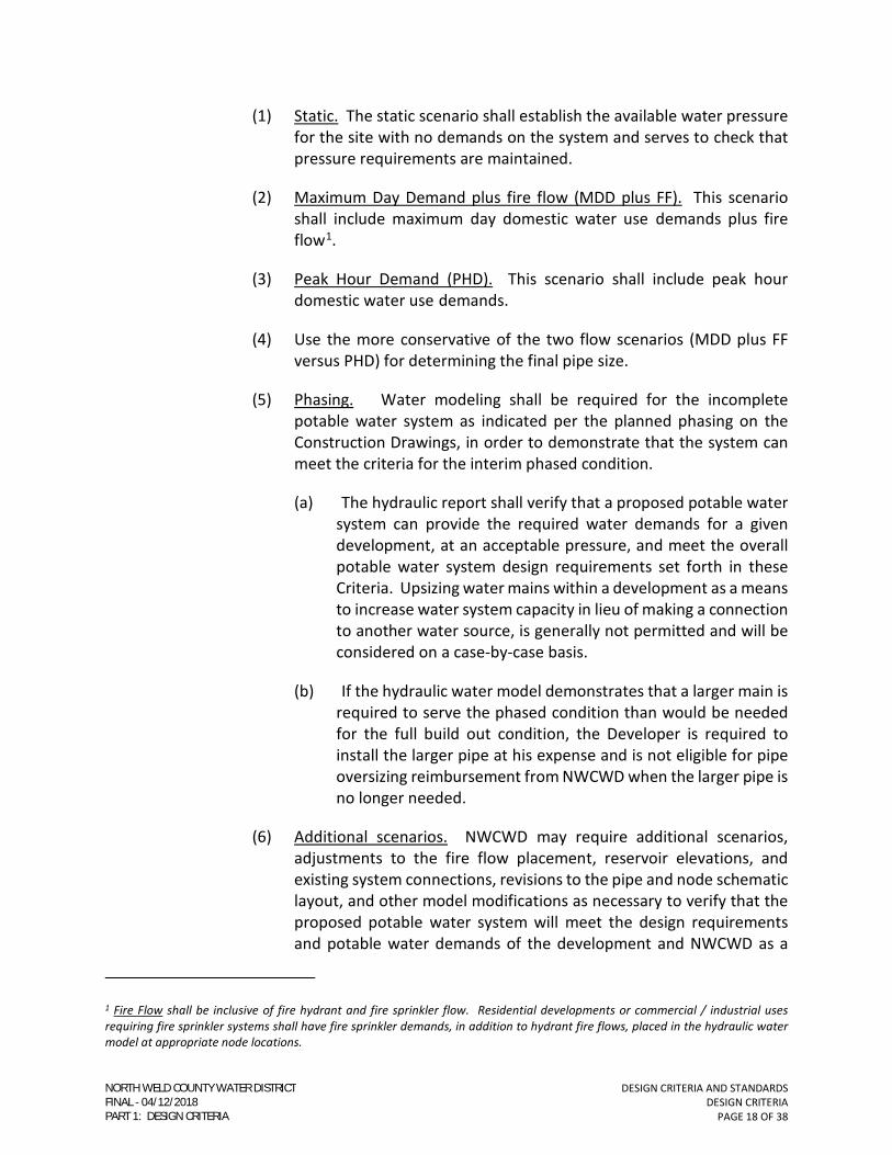
(1) Static. The static scenario shall establish the available water pressure
for the site with no demands on the system and serves to check that
pressure requirements are maintained.
(2) Maximum Day Demand plus fire flow (MDD plus FF). This scenario
shall include maximum day domestic water use demands plus fire
flow1.
(3) Peak Hour Demand (PHD). This scenario shall include peak hour
domestic water use demands.
(4) Use the more conservative of the two flow scenarios (MDD plus FF
versus PHD) for determining the final pipe size.
(5) Phasing. Water modeling shall be required for the incomplete
potable water system as indicated per the planned phasing on the
Construction Drawings, in order to demonstrate that the system can
meet the criteria for the interim phased condition.
(a) The hydraulic report shall verify that a proposed potable water
system can provide the required water demands for a given
development, at an acceptable pressure, and meet the overall
potable water system design requirements set forth in these
Criteria. Upsizing water mains within a development as a means
to increase water system capacity in lieu of making a connection
to another water source, is generally not permitted and will be
considered on a case-by-case basis.
(b) If the hydraulic water model demonstrates that a larger main is
required to serve the phased condition than would be needed
for the full build out condition, the Developer is required to
install the larger pipe at his expense and is not eligible for pipe
oversizing reimbursement from NWCWD when the larger pipe is
no longer needed.
(6) Additional scenarios. NWCWD may require additional scenarios,
adjustments to the fire flow placement, reservoir elevations, and
existing system connections, revisions to the pipe and node schematic
layout, and other model modifications as necessary to verify that the
proposed potable water system will meet the design requirements
and potable water demands of the development and NWCWD as a
1 Fire Flow shall be inclusive of fire hydrant and fire sprinkler flow. Residential developments or commercial / industrial uses
requiring fire sprinkler systems shall have fire sprinkler demands, in addition to hydrant fire flows, placed in the hydraulic water
model at appropriate node locations.
NORTH WELD COUNTY WATER DISTRICTFINAL 04/12/2018PART 1: DESIGN CRITERIA

DESIGN CRITERIA AND STANDARDS
DESIGN CRITERIA
PAGE 19 OF 38
whole. At NWCWD’s discretion, the existing or future potable water
system beyond the limits of the proposed development may require
modeling as part of the hydraulic analysis. This analysis will be
performed by NWCWD.
b. Modeling Procedure
(1) Connections to the existing potable water distribution system are
typically denoted as reservoirs with the same hydraulic grade
elevation. NWCWD shall provide inflow pressure.
(2) Place estimated domestic water, fire sprinkler, and irrigation tap
demands at appropriate node locations within the model as they
relate within the project.
(3) Locate fire flow demands at hydrant locations according to the
modeling scenarios in Section 2.07.C.7 of these Criteria. The
maximum allowable fire flow provided from any one (1) hydrant shall
be 1,500 gpm. If the required fire flow is in excess of 1,500 gpm, the
next closest hydrant shall be used until the required fire flow is met.
(4) Depending on the location of the development, existing potable water
system performance and reliability in the area, number of available
potable water connections, and surrounding land uses, some of the
project’s proposed potable water connections may require modeling
as a demand point or no connection instead of a water source.
NWCWD shall provide additional outflow demands for a development
on a case by case basis.
8. Potable Water System Report Results
a. Provide a schematic layout of the potable water distribution system showing
and labeling the reservoir connections, pipe network, and demand nodes as
presented and analyzed for each water model scenario.
b. Provide a Reservoir Report for the static condition. The Reservoir Report
shall include the following information:
(1) Reservoir Identification Label; and
(2) Elevation (ft).
c. Provide Pipe Reports for all modeled scenarios. Pipe Reports shall include
the following information:
(1) Modeled Scenario Title;
NORTH WELD COUNTY WATER DISTRICTFINAL 04/12/2018PART 1: DESIGN CRITERIA
DESIGN CRITERIA AND STANDARDS
DESIGN CRITERIA
PAGE 20 OF 38
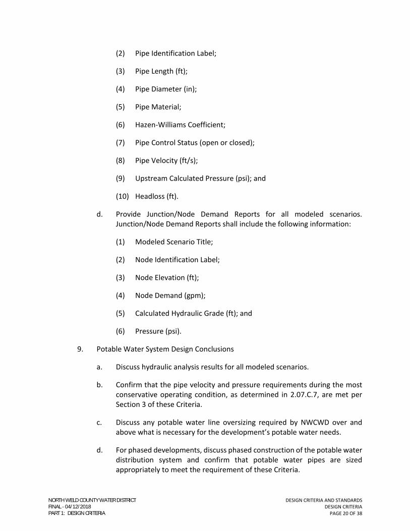
(2) Pipe Identification Label;
(3) Pipe Length (ft);
(4) Pipe Diameter (in);
(5) Pipe Material;
(6) Hazen-Williams Coefficient;
(7) Pipe Control Status (open or closed);
(8) Pipe Velocity (ft/s);
(9) Upstream Calculated Pressure (psi); and
(10) Headloss (ft).
d. Provide Junction/Node Demand Reports for all modeled scenarios.
Junction/Node Demand Reports shall include the following information:
(1) Modeled Scenario Title;
(2) Node Identification Label;
(3) Node Elevation (ft);
(4) Node Demand (gpm);
(5) Calculated Hydraulic Grade (ft); and
(6) Pressure (psi).
9. Potable Water System Design Conclusions
a. Discuss hydraulic analysis results for all modeled scenarios.
b. Confirm that the pipe velocity and pressure requirements during the most
conservative operating condition, as determined in 2.07.C.7, are met per
Section 3 of these Criteria.
c. Discuss any potable water line oversizing required by NWCWD over and
above what is necessary for the development’s potable water needs.
d. For phased developments, discuss phased construction of the potable water
distribution system and confirm that potable water pipes are sized
appropriately to meet the requirement of these Criteria.
NORTH WELD COUNTY WATER DISTRICTFINAL 04/12/2018PART 1: DESIGN CRITERIA

DESIGN CRITERIA AND STANDARDS
DESIGN CRITERIA
PAGE 21 OF 38
2.08. AS-CONSTRUCTED RECORD DRAWING REQUIREMENTS
A. The Contractor and Design Engineer shall be responsible for recording As-Constructed
information on a set of Record Drawings kept at the construction site. A representative
of the Developer shall monitor construction to assure that changes in construction (as
approved in writing) and other pertinent details, such as horizontal location of fittings
and manholes, valves, top of pipe elevations, manhole inverts, service tap locations, pipe
sizes, depths, etc. are kept current on the As-Constructed Record Drawings.
B. Where the construction is phased with a more than 30-day lapse between phases, As-
Constructed Record Drawings shall be submitted to NWCWD after each completed
phase. The Construction Drawings for all future phases shall also reflect the “As-
Constructed” conditions of the previous phases.
C. At a minimum, the As-Constructed Record Drawings set shall include the following
sheets from the original accepted Construction Drawings:
1. Cover Sheet;
2. Utility Plan;
3. All potable water (and non-potable irrigation, if applicable) plan and profile
sheets; and
4. All construction details and NWCWD Standard Drawings that were used in the
construction of the potable water distribution system and non-potable irrigation.
D. The As-Constructed Record Drawings shall show the original design information as well
as the As-Constructed information. The original design information shall be shown as
“lined through”. The As-Constructed information shall be located in the same areas as
the design information and shall be either “clouded” and/or made with a heavier line
weight as the design information for clear differentiation. The month and year of the
construction shall also be noted.
E. As-Constructed Record Drawings shall be submitted to NWCWD prior to issuance of
Substantial Completion. The two (2) year warranty period for the installed potable
water system will begin after the Certificate of Conditional Acceptance has been issued
by NWCWD. The request for the Conditional Acceptance may be initiated by NWCWD
or requested by the Developer, but in all cases is the sole responsibility of the Developer.
F. NWCWD will compare the As-Constructed Record Drawing information with the
approved Construction Drawings and information NWCWD may be aware of during the
construction process. Any corrections, additions, or omissions to the As-Constructed
Record Drawings shall be provided to the Design Engineer who prepared the As-
Constructed Drawings for changes.
NORTH WELD COUNTY WATER DISTRICTFINAL 04/12/2018PART 1: DESIGN CRITERIA

DESIGN CRITERIA AND STANDARDS
DESIGN CRITERIA
PAGE 22 OF 38
G. The Certificate of Final Acceptance, which occurs at the end of the warranty period, will
NOT be granted until the As-Constructed Drawings for the potable water system are
accepted by NWCWD.
2.09. REIMBURSEMENT FOR MAIN DESIGN AND INSTALLATION COSTS
A. NWCWD may require the Developer to install a potable water main larger than is
needed to adequately serve the development. Said oversizing shall be agreed upon with
Development and incorporated into the Water Service Agreement for such
Development.
B. If the Developer is required to design and construct off site potable water mains in order
to serve the development, the Developer may be eligible for design and construction
cost reimbursements from other developments that connect to that main. If the
Developer connects to potable water main constructed by another party or NWCWD,
the Developer may be required to participate in the design and construction costs of
those lines. Refer to NWCWD’s “waterline extension reimbursement policy.”
NORTH WELD COUNTY WATER DISTRICTFINAL 04/12/2018PART 1: DESIGN CRITERIA
DESIGN CRITERIA AND STANDARDS
DESIGN CRITERIA
PAGE 23 OF 38
SECTION 3 - POTABLE WATER DISTRIBUTION SYSTEM DESIGN CRITERIA
3.01. GENERAL
A. The purpose of this section is to provide information for the design and layout of a
potable water distribution system. Potable water distribution system design shall be in
accordance with NWCWD’s Water System Master Plan, latest revision, and these
Criteria.
B. This section is not intended to be inclusive of all situations and the Design Engineer may
be required to use additional engineering judgment to meet the overall design intent
for constructability and long-term operations and maintenance. This Design Criteria
typically applies to potable water mains sixteen-inches (16”) in diameter and smaller.
The District Engineer reserves the right to make final determinations of the system
design based on the best interest of NWCWD’s system.
3.02. DEFINITIONS
A. Potable Water Distribution Mains
1. A potable water distribution main is a water pipe that primarily serves as a delivery
conduit to transport potable water from transmission mains directly to individual
water services.
2. Potable water distribution mains within NWCWD are four-inches (4”), six-inches
(6”), eight-inches (8”), twelve-inches (12”), and sixteen-inches (16”) in diameter.
a. Ten-inch (10”) and fourteen-inch (14”) shall no longer be installed in
NWCWD’s service area.
B. Potable Water Transmission Mains
1. A potable water transmission main is a water pipe that primarily serves as a
delivery conduit to transport potable water directly to the distribution mains.
2. Potable water transmission mains are eighteen-inches (18”) and larger in
diameter.
a. In some cases, pipes smaller than eighteen-inches (18”) may be classified as
transmission mains.
C. Potable Water Services
1. Potable water services include all piping, fittings, and appurtenances used to
convey potable water from the distribution main to the customer.
NORTH WELD COUNTY WATER DISTRICTFINAL 04/12/2018PART 1: DESIGN CRITERIA

DESIGN CRITERIA AND STANDARDS
DESIGN CRITERIA
PAGE 24 OF 38
3.03. DESIGN FLOW
A. The potable water distribution system shall be designed to transport the most
conservative of maximum day demand plus fire flow or peak hour flow.
1. Ensure hydrant fire flow and fire sprinkler system flow requirements are satisfied
and are described in the Potable Water System Report, per Section 2.07.C.6.d.
B. All water demands used in the design of potable water distribution systems are subject
to approval by NWCWD.
C. Design Flow
1. The water demand criteria presented in the following tables are minimum criteria.
These criteria are divided into urban and rural categories based on land use and
water tap usage classification, respectively. The urban criteria are applicable to
subdivisions and planned unit developments (PUDs) that include single family
residential, multifamily residential, and commercial/retail land uses. The
residential urban criteria are based on the number of units per acre (density),
whereas the commercial urban criteria are based on building square footage. The
rural criteria are based on the water tap usage classifications indicated on the
NWCWD water tap fee schedule, latest revision.
2. NWCWD reserves the right to modify the Criteria, at any time, for the design of
specific projects. Potable water demand criteria for uses not provided in the
tables below shall be determined during system design. Where applicable, these
design flows shall be determined in accordance with fixture unit methods
described in AWWA M22 – SIZING SERVICE LINES AND METERS.
NORTH WELD COUNTY WATER DISTRICTFINAL 04/12/2018PART 1: DESIGN CRITERIA

DESIGN CRITERIA AND STANDARDS
DESIGN CRITERIA
PAGE 25 OF 38
Table 3-1: Potable Water Design Flow – Urban Residential
Usage Classification
Units per
Acre
Average Day
Demand
(gpm/unit)
Maximum Day
Demand
(gpm/unit)
Peak Hour
Demand
(gpm/unit)
Single Family – Low
Density 1 - 5 0.5 0.7 1.9
Single Family – High
Density 6 - 10 0.4 0.6 1.7
Multifamily 11 - 20 0.3 0.4 1.1
Notes: Irrigation is included in the residential water demands for Low and High Density Single Family, but not included for
Multifamily.
Table 3-2: Potable Water Design Flow – Urban Commercial
Usage Classification
Average Day
Demand
(gpm)
Maximum Day
Demand
(gpm)
Peak Hour
Demand
(gpm)
Office Building or Small
Business 0.14 0.21 0.60
Restaurant 0.35 0.53 1.50
Supermarket, Big Box, Dept.
Store 0.14 0.21 0.60
Laundry, Dry Cleaning 0.70 1.10 2.90
Service Station (No Car Wash) 0.02 0.04 0.08
Car Wash 1.32 2.00 5.50
Hotel/Motel 0.24 0.36 1.00
Warehouse (Non-industrial) 0.07 0.11 0.30
Irrigation N/A N/A 24 gpm/acre
3. Irrigation water is not included in the urban multifamily or commercial water
demands. Irrigation demands for urban multifamily and commercial uses shall
NORTH WELD COUNTY WATER DISTRICTFINAL 04/12/2018PART 1: DESIGN CRITERIA

DESIGN CRITERIA AND STANDARDS
DESIGN CRITERIA
PAGE 26 OF 38
be determined using a peak hour demand rate of twenty-four gallons per minute
per acre (24 gpm/acre) and the estimated irrigated acreage.
Table 3-3: Potable Water Design Flow – Rural
Usage Classification2 Maximum Day Demand (gpm/tap) Peak Hour Demand (gpm/tap)3
Full Standard 5.00 7.70
Conservation Blue 5.00 7.70
75% Tap 3.75 5.80
50% Tap 2.50 3.90
Table 3-4: Potable Water Design Flow – Industrial
Usage Classification
Maximum Day Demand
(gpm/tap)
Peak Hour Demand
(gpm/tap)
Potable water demands have not been provided for industrial uses. Due to the extreme
variation in water consumption amongst the different types of industry, industrial water
demands shall be determined during system design when the industrial use is known.
D. Fire Flows
1. Contact the appropriate fire/rescue authority for the latest adopted fire code and
to confirm project fire flow requirements.
2. For design purposes, the maximum allowable fire flow provided from any one (1)
hydrant is 1,500 gpm. Fire flow may be obtained from more than one (1) fire
hydrant providing the additional hydrants are accessible to any possible fire
location and meet the spacing requirements and distances from structures as
specified in Section 3.18 of these Criteria and by the appropriate fire/rescue
authority.
3.04. PRESSURE REQUIREMENTS
A. Potable water distribution systems must be designed to provide minimum and
maximum system pressures as discussed in the following sections. Water system
pressure information for NWCWD’s existing system may only be obtained from
NWCWD.
2 Refer to current NWCWD tap fee schedule 3 1.54 times the Maximum Day Demand
NORTH WELD COUNTY WATER DISTRICTFINAL 04/12/2018PART 1: DESIGN CRITERIA
DESIGN CRITERIA AND STANDARDS
DESIGN CRITERIA
PAGE 27 OF 38
1. The potable water distribution system in all areas shall be designed for a maximum
pressure of 145 psi and a minimum pressure of 45 psi for normal conditions.
2. Twenty (20) psi residual pressure is required at any one (1) hydrant with maximum
day plus fire flow demands.
3. Pressure zones shall conform to existing NWCWD’s pressure zones as provided in
the Water System Master Plan, latest revision. Specific information on the
pressure zones or to confirm which pressure zone a development or site is actually
located may only be obtained from NWCWD.
4. Pressure regulating valves (PRV) will be required between pressure zones. The
PRV location shall be determined by NWCWD.
3.05. HYDRAULIC DESIGN
A. Friction Coefficient
1. Potable distribution mains shall be designed using a Hazen-Williams friction
coefficient “C” equal to:
a. 150 for PVC pipe; or
b. 130 for all other pipe materials.
B. Velocity
1. All pipes shall be sized for a maximum water velocity of no greater than ten (10)
feet per second (fps) for any max day plus fire flow; fire hydrant laterals are
exempt.
C. Head Loss
1. Maximum allowable head loss in pipes twelve-inches (12”) in diameter or less,
shall not exceed ten (10) feet of head loss per 1,000 linear feet of pipe (10 ft/1,000
ft). This does not apply to fire flow analysis.
2. Maximum allowable head loss in pipes sixteen-inches (16”) in diameter shall not
exceed five (5) feet of head loss per 1,000 linear feet of pipe (5 ft/1,000 ft). This
does not apply to fire flow analysis.
3. Pipes larger than sixteen-inches (16”), e.g., transmission mains, shall be evaluated
on a case-by-case basis in coordination with NWCWD. In general, allowable unit
head loss will be lower than those values stated above for pipes through sixteen-
inches (16”).
NORTH WELD COUNTY WATER DISTRICTFINAL 04/12/2018PART 1: DESIGN CRITERIA

DESIGN CRITERIA AND STANDARDS
DESIGN CRITERIA
PAGE 28 OF 38
3.06. POTABLE WATER MAIN SIZE
A. Mains shall be sized appropriately to meet the criteria in Section 3.05. Distribution
mains shall have a minimum diameter of four-inches (4”).
B. Hydrant leads connecting to the distribution system shall be six-inch (6”). Other pipe
diameters for hydrant leads are prohibited.
3.07. DEPTH OF BURY
A. Cover depth (minimum and maximum) shall be as specified on Standard Detail No.
3300001, GENERAL UTILITY NOTES.
B. When design or constructability constraints are present, deeper or shallower water
main installation may be permitted only with acceptance from NWCWD. Additional
design and installation considerations may be required by NWCWD depending on the
situation.
3.08. CONNECTIONS TO THE EXISTING POTABLE WATER SYSTEM
A. Main connections to the existing potable water distribution system may be made by wet
tap or by a cut in tee.
B. The Contractor shall make all wet taps on the existing system using qualified personnel
under the direct supervision of NWCWD. Refer to Standard Specification Section 33 05
10, Tapping Sleeves and Valves, for requirements. The Contractor is responsible for
providing all tapping materials, e.g., tapping sleeves, tapping valves, insulator kits, etc.
C. All cut-in tees shall be made by the Contractor under the direct supervision of NWCWD.
D. For direct wet taps on existing waterlines, manufacturer’s shop drawings and
specifications for the proposed tapping sleeve shall be submitted to NWCWD for review
and acceptance prior to installation of the tapping sleeve by the Contractor.
3.09. LOCATION AND LOOPING OF POTABLE WATER MAINS
A. Potable water mains shall be located in a dedicated street right-of-way, where feasible,
or within a dedicated exclusive easement of appropriate width.
B. The centerline of potable water mains shall not be placed closer than six (6) feet to the
lip of street gutter.
C. Potable water mains serving a cul-de-sac shall be extended to within ten (10) feet of the
lip of street gutter at the end of the cul-de-sac and shall have a hydrant assembly placed
on the end of the line. Permanent dead-ends in urban subdivision cul-de-sacs, longer
than 300 feet, are prohibited.
NORTH WELD COUNTY WATER DISTRICTFINAL 04/12/2018PART 1: DESIGN CRITERIA

DESIGN CRITERIA AND STANDARDS
DESIGN CRITERIA
PAGE 29 OF 38
D. A potable water main serving one (1) lot shall extend all the way across the frontage for
that lot.
E. Temporary dead-ends shall have a hydrant blowoff at the end of the line.
F. An adequate number of connections to the existing potable water distribution system
shall be provided such that no more than fifteen (15) single family units, or the
equivalent single family flow for non-residential developments, are out of service at any
one time.
1. Water line extensions, including offsite water line connections, shall be extended
along dedicated street right-of-way along the property frontage, in order to
provide a gridded water system for future connections. Property or subdivision
interiors will be served by connecting to the water line extensions. Potable water
mains shall extend to the extremities of the property or the subdivision served.
NWCWD shall determine the need for gridded water line extensions on a case-by-
case basis.
a. Line Extension Reimbursement Policy may apply on a case-by-case basis as
determined by NWCWD.
2. Extensions shall be in appropriate locations to provide adequate water
connections and to maintain looping requirements for adjacent, future
developments.
3. Water mains shall be extended offsite when required to tie into the existing
distribution system for additional water source connections. Appropriately sized
easements shall be provided.
G. In all instances, NWCWD shall determine the potable water system looping for a
development on a case by case basis and may require additional potable water
connections over and above those demonstrated by a hydraulic analysis in order to
maintain overall water system performance. Ultimately, the required source
connections to the existing potable water system shall be solely determined by
NWCWD.
3.10. POTABLE WATER SYSTEM PHASED INSTALLATION AND STUBOUTS
A. Potable water distribution system phasing, if proposed by the Developer, shall be clearly
identified on the master utility plan. Water plan and profile sheets shall clearly show
and label the phasing transitions in the potable water line design.
B. The proposed potable water system phasing shall maintain looping integrity within the
system.
NORTH WELD COUNTY WATER DISTRICTFINAL 04/12/2018PART 1: DESIGN CRITERIA
DESIGN CRITERIA AND STANDARDS
DESIGN CRITERIA
PAGE 30 OF 38
C. The phased potable water system design shall meet the phased water demands for the
development and adhere to all potable water system and hydraulic design requirements
provided in these Criteria.
D. Locate line valves and temporary hydrant blowoffs at the end of each phase or stubout.
The stubout shall be shown on the potable water plan and profile sheets.
E. Phased water line or stubout construction shall be extended a minimum ten (10) feet
beyond phased street paving to avoid asphalt removal during excavation for future
connections.
F. Phased potable water mains or stubouts intended for future connections shall be valved
such that only one (1) valve needs to be closed when the main is extended and no
customers are without water service when the line is extended. The valve must be
appropriately restrained so that it will not “blow off” when the water line is exposed
and all thrust blocking is removed for the extension. See Section 3.14 of these Criteria
regarding pipe restraint.
G. The maximum length of a stubout shall be fifty (50) feet unless otherwise approved by
NWCWD.
H. Potable water main stubouts not utilized shall be abandoned.
3.11. PIPE MATERIAL
A. Potable water pipes less than or equal to twenty-four-inches (24”) in diameter may be
AWWA C151 cement-lined ductile iron pipe or AWWA C900 polyvinyl chloride (PVC)
pressure pipe.
B. Potable water pipes larger than twenty-four-inches (24”) in diameter shall be AWWA
C151 cement- lined ductile iron pipe. AWWA C900 polyvinyl chloride (PVC) pressure
pipe may be considered by NWCWD on a case-by-case basis.
C. The Design Engineer shall specify the pipe material and class as required for specific
project conditions. The pipe material and class shall be called out on the Construction
Drawings.
D. All buried ductile iron pipe, fittings, and valves shall be polyethylene-encased in
accordance with AWWA C105.
3.12. VALVES
A. All valves shall be located in dedicated street right-of-way or within a dedicated
exclusive easement of appropriate width.
B. Inline Isolation Valves
NORTH WELD COUNTY WATER DISTRICTFINAL 04/12/2018PART 1: DESIGN CRITERIA
DESIGN CRITERIA AND STANDARDS
DESIGN CRITERIA
PAGE 31 OF 38
a. Install inline isolation valves on all branches of tees and crosses, excluding
the runs of hydrant tees.
b. Inline isolation valves are assigned in the potable water distribution system
so that no single accident, break, or repair necessitates shutting down a
nominal length of pipe greater than 1,000 feet.
c. Inline isolation valves shall be located a minimum five (5) feet from the edge
of concrete cross pans.
d. All inline isolation valves shall have a concrete collar around the valve box if
located in asphalt pavement, unless directed otherwise by the municipality.
e. Inline isolation valves shall be:
(1) Gate Valves
(a) For mains through twelve-inch (12”).
(b) Fire hydrant and fire sprinkler line gate valves shall be placed at
the main. These gate valves shall be mechanical joint valves and
fasten to a mechanical joint anchor tee (swivel tee) on the main.
(2) Butterfly Valves
(a) For mains larger than twelve-inch (12”).
C. Air Valves
1. NWCWD will determine the locations of air valves to be installed along the main
and shall be properly sized by the Design Engineer in accordance with the
manufacturer’s recommendations. NWCWD shall have final determination on air
valve type, size, and placement of the following:
a. Air Release Valves (ARV)
(1) ARVs release small volumes of accumulated air from a pipeline during
filling operations and while the system operates under pressure
exceeding atmospheric pressure.
b. Air Release/Vacuum Relief Valves (AVV)
(1) AVVs release large volumes of air automatically during pipeline filling
and admit large volumes of air automatically when the internal
pressure in the pipeline drops below atmospheric pressure.
c. Combination Air Valves (CAV)
NORTH WELD COUNTY WATER DISTRICTFINAL 04/12/2018PART 1: DESIGN CRITERIA

DESIGN CRITERIA AND STANDARDS
DESIGN CRITERIA
PAGE 32 OF 38
(1) CAVs perform the same functions as an ARV and an AVV.
(2) In general, only CAVs will be installed, unless approved otherwise by
NWCWD.
D. Pressure Regulating Valves
1. Pressure regulating valves (PRVs) control pressures between potable water
distribution system pressure zones.
2. The need for a PRV, its size, and its installation location shall be determined by
NWCWD.
3.13. CURVED PIPE ALIGNMENT
A. Potable water mains may be curved to change alignment or grade or to avoid
obstructions, within the limits of curvature of the pipe. If a curved alignment is not
feasible or permitted by NWCWD, appropriate fitting(s) shall be used, e.g., elbows.
B. Allowable Joint Offset
1. PVC Pipe
a. Limit joint offset to no more than 80% of manufacturers recommended joint
deflection for a given pressure class and diameter.
b. PVC pipe may be joined with High Deflection (HD) Couplings which allow five
degrees (5°) of pipe joint deflection per coupling. HD couplings can be
used in the place of small bends or where it is undesirable or impossible to
bend the pipe.
c. Longitudinal Bending
(1) PVC pipe, per AWWA C900, may be installed in accordance with the
longitudinal bending guidance outlined in AWWA C605, latest edition.
2. Ductile Iron Pipe
a. Limit joint offset to no more than 80% of manufacturers recommended joint
deflection for a given pressure class and diameter.
3.14. THRUST RESTRAINT
A. Thrust Blocks
1. Concrete thrust blocks shall be constructed only at main line connections where
the restraint of the existing pipe is in question.
NORTH WELD COUNTY WATER DISTRICTFINAL 04/12/2018PART 1: DESIGN CRITERIA

DESIGN CRITERIA AND STANDARDS
DESIGN CRITERIA
PAGE 33 OF 38
2. The Design Engineer shall determine the required size of thrust blocks to use and
NWCWD will have the final determination on size and placement.
B. Restrained Joints
1. All horizontal and vertical bends (tees, crosses, elbows, etc.), dead-ends, and inline
isolation valves shall be restrained by a mechanical restraint system, e.g.,
restrained push-on or mechanical joint restraints.
2. The Design Engineer shall determine the length of required pipe restraint, for the
pipe material being used, PVC or DIP, in accordance with AWWA M41 Ductile-Iron
Pipe and Fittings or AWWA M23 PVC Pipe – Design and Installation, latest revision.
a. Refer to the Standard Details for pipe sizes through sixteen-inch (16”).
b. Restraint calculations shall be submitted to NWCWD for review and
acceptance.
c. Restrained length(s) shall be provided on the Construction Drawings.
d. All situations not listed above that may cause an unbalanced thrust
situation, e.g., reducers, shall be analyzed by the Design Engineer.
C. In some instances, e.g., fire hydrants, large diameter fire lines, water line lowerings, etc.,
thrust blocks may be required in addition to restrained joints. NWCWD shall make such
determinations on a case-by-case basis.
3.15. POTABLE WATER MAIN AND SERVICE ENCASEMENTS
A. No general statement can be made to cover all encasement conditions; therefore, only
typical encasement situations are addressed in this section. Encasement requirements
shall ultimately be determined by NWCWD on a case-by-case basis.
B. An encasement shall be considered the open-trench installation of a casing pipe.
C. The use of “line” or “lines” in this section shall refer to both mains and services.
D. Encasements
1. Where sanitary sewer lines cross beneath potable water lines with less than
eighteen (18) inches clearance, sanitary sewer lines cross above potable water
lines, or the ten (10) feet horizontal clearance between potable water lines and
sanitary sewer lines cannot be maintained, pipe encasement shall be designed and
constructed so as to protect the potable water line.
NORTH WELD COUNTY WATER DISTRICTFINAL 04/12/2018PART 1: DESIGN CRITERIA

DESIGN CRITERIA AND STANDARDS
DESIGN CRITERIA
PAGE 34 OF 38
2. Where non-potable irrigation lines cross above or below potable water lines with
less than eighteen (18) inches clearance, pipe encasement shall be designed and
constructed so as to protect the potable water line.
3. Pipe encasement shall be placed on the sanitary sewer line or non-potable
irrigation line except in situations where the sanitary sewer or non-potable
irrigation line is existing. Where the sanitary sewer or non-potable irrigation line
is already constructed, the pipe encasement shall be placed on the potable water
line.
4. The encasement pipe shall extend a minimum ten (10) feet on either side of the
crossing measured from the outside diameter of the crossed pipe. Longer casing
pipes may be required depending on the encasement situation.
5. For any atypical encasement situations, the Design Engineer shall size the
encasement pipe such that the inside clearance is at least one-inch (1”) greater
than the maximum outside diameter of the casing spacer runners. Refer to
Specification Section 33 05 08, Pipe Boring and Jacking, for encasement pipe
material, diameter, and wall thickness (if applicable), casing spacers, end seals,
and installation requirements.
E. Encasements Required by Other Agencies
1. For potable water mains crossing another agency’s right of way or easement, the
encasement requirements for that crossing shall be specified by the agency
granting permission to cross. Such crossings shall be subject to approval by
NWCWD to avoid conflicts in requirements or standards between NWCWD and
the agency granting permission to cross.
2. A letter, permit, or approved crossing application from the agency granting
permission to cross, must be provided to NWCWD before the crossing will be
approved by NWCWD.
3. NWCWD shall not accept any crossings imposed with an annual user or crossing
fee from the agency granting permission to cross. All crossing fees, if applicable,
shall be paid by the Developer prior to installation of the encasement.
3.16. POTABLE WATER SERVICES AND FIRE SPRINKLER LINES
A. General
1. Potable water service lines shall not be installed in trenches with other
conduits/utilities. A service line shall be separated from other conduits a
minimum ten (10) feet horizontally and eighteen (18) inches vertically. The only
exception will be a fire sprinkler line. In this instance, the horizontal separation
may be a minimum of five (5) feet, from outside diameter of the pipe. Larger
NORTH WELD COUNTY WATER DISTRICTFINAL 04/12/2018PART 1: DESIGN CRITERIA
DESIGN CRITERIA AND STANDARDS
DESIGN CRITERIA
PAGE 35 OF 38
diameter potable water services and fire sprinkler lines may still require ten (10)
feet horizontal separation. This shall be evaluated by NWCWD on a case by case
basis.
2. Potable water services and fire sprinkler lines for a given lot must be tapped on
the potable water main within the confines of the property lines extended.
3. No potable water service taps shall be made on fire sprinkler lines.
4. Potable water services and fire sprinkler lines not utilized shall be abandoned. The
service line shall be cut at the main and the line capped.
B. Water Services
1. Potable water services shall be polyethylene tubing, per Section 33 14 18 of the
Standard Specifications.
2. A separate potable water service line and meter must serve each premise.
3. No potable water service lines shall cross property lines.
4. Pressure boosters are prohibited without adequate backflow protection.
5. Potable water services shall be located five (5) feet from the side lot line and
paired with an adjacent lot, wherever feasible.
a. Refer to the “WATER SERVICE LOCATION PLAN” in the Standard Details.
6. Under no condition is a potable water service to be located under driveways,
trees, or other permanent structures.
7. Potable water service taps shall be located as specified in Section 33 14 18 –
SERVICE LINES AND APPURTENANCES.
8. Potable water service curb stops shall be located ± one (1) foot from the property
line or easement boundary. Potable water service meter pits/vaults shall be
located as close as possible beyond the curb stop. Refer to the Standard
Specifications and Standard Details for additional service and meter installation
requirements.
9. Potable water service meter pits/vaults shall normally be located after the curb
stop in a landscaped area. Meter pits/vaults shall not be installed in any street,
parking area, driveway, or sidewalk unless otherwise approved by NWCWD.
Meter pit/vault shall be rated for HS-20 traffic loadings unless otherwise
permitted by NWCWD. Curbstops in paved areas shall be in a street valve box.
NORTH WELD COUNTY WATER DISTRICTFINAL 04/12/2018PART 1: DESIGN CRITERIA

DESIGN CRITERIA AND STANDARDS
DESIGN CRITERIA
PAGE 36 OF 38
10. There shall be no major landscaping (trees, boulders, or shrubs with mature
growth greater than three (3) feet), buildings, or other permanent structures
within ten (10) feet of the meter pit/vault.
C. Fire Sprinkler Lines
1. Fire sprinkler lines shall be a minimum of four-inch (4”) to the meter vault. Fire
sprinkler lines larger than four-inch (4”) shall be restrained C900 PVC pipe or DIP.
Fire sprinkler lines require a gate valve at the main.
a. ALL fire sprinkler lines are metered.
2. Refer to the Standard Details for meter vault details.
3.17. POTABLE WATER MAINS AND SERVICES IN RELATION TO OTHER UTILITIES
A. Potable water services and distribution mains shall have a minimum ten (10) feet
horizontal and eighteen (18) inches vertical separation from all utilities measured from
outside diameter.
B. Where sanitary sewer lines cross beneath potable water lines with less than eighteen
(18) inches of clearance, sanitary sewer lines cross above potable water lines, or the ten
(10) feet horizontal clearance between potable water lines and sanitary sewer lines
cannot be maintained, pipe encasement shall be designed and constructed so as to
protect the potable water main.
C. Where storm water lines cross above potable water mains, storm water pipe joints shall
be grouted a minimum ten (10) feet on either side of the crossed potable water main,
measured from the outside diameter of the pipe.
D. Potable water main crossings under any open irrigation ditch shall have a minimum of
five (5) feet of cover and shall be encased.
E. Right angle utility crossings are permitted above and below the potable water main.
Parallel installation of other utilities in exclusive water easements is not permitted.
F. Bored utility crossings shall have a minimum twenty-four (24) inches of vertical
clearance from the outside diameter of the utility casing to the outside diameter of the
potable water line if the bored utility crosses above the potable water line and a
minimum of thirty-six (36) inches of vertical clearance from the outside diameter of the
utility casing to the outside diameter of the potable water line if the bored utility crosses
below the water line.
G. If there are horizontal or vertical clearance conflicts between the potable water line and
a utility, NWCWD may require that the potable water main be lowered, raised, or
realigned in order to maintain the required clearances.
NORTH WELD COUNTY WATER DISTRICTFINAL 04/12/2018PART 1: DESIGN CRITERIA

DESIGN CRITERIA AND STANDARDS
DESIGN CRITERIA
PAGE 37 OF 38
H. For a potable water line crossing situation not specifically mentioned in this section, the
crossing requirements provided in these Criteria shall be applied to that particular
situation to the best extent possible.
3.18. FIRE PROTECTION AND HYDRANT SPACING
A. All fire protection, fire flow, hydrant spacing, and hydrant requirements are subject to
approval by the governing fire protection agency.
1. Fire Protection Agencies within NWCWD’s service area
a. Refer to Section 33 14 22 of the Standard Specifications.
B. Hydrants shall be located at intersections whenever possible. Hydrants located mid-
block shall be aligned with the extension of a property line.
C. Fire hydrants shall be placed at the end of cul-de-sac.
D. Fire hydrants shall be installed in accordance with Section 33 14 22 of the Standard
Specifications and with the Standard Details, as applicable.
E. A three (3) foot radius in all directions around the hydrant shall be clear of obstructions.
1. Where hydrants are vulnerable to vehicular damage, crash posts shall be provided
outside of the three (3) foot radius clearance in all directions from the hydrant.
2. Crash posts, i.e., bollards, shall be concrete filled pipes that are four-inches (4”) in
diameter and a minimum of four (4) feet in height above the finished ground
surface with two (2) feet of post below the finished ground surface.
F. All hydrants must be within dedicated easements or public rights-of-way.
3.19. CROSS CONNECTION AND BACKFLOW PREVENTION
A. Potable water service lines on any property or inside any building shall have NO physical
connection with any pipes, pumps, hydrants, tanks, or non-potable irrigation systems
that could draw or discharge any unsafe or contaminated water (including steam
condensation or cooling water) into the potable water distribution system.
B. For additional information on cross connection or backflow prevention requirements,
refer to NWCWD’s Backflow Preventions policy.
C. Refer to Section 33 14 10 of the Standard Specifications for requirements.
END OF DESIGN CRITERIA
NORTH WELD COUNTY WATER DISTRICTFINAL 04/12/2018PART 1: DESIGN CRITERIA

DESIGN CRITERIA AND STANDARDS
DESIGN CRITERIA
PAGE 38 OF 38
(THIS PAGE INTENTIONALLY LEFT BLANK)
NORTH WELD COUNTY WATER DISTRICTFINAL 04/12/2018PART 1: DESIGN CRITERIA

DESIGN CRITERIA AND STANDARDS
POTABLE WATER DISTRIBUTION SYSTEM
PART 2
STANDARD SPECIFICATIONS

(THIS PAGE INTENTIONALLY LEFT BLANK)

SECTION 00 01 10
TABLE OF CONTENTS
PAGE 1 OF 2
SECTION 00 01 10
TABLE OF CONTENTS
DIVISION 00 PROCUREMENT AND CONTRACTING REQUIREMENTS
00 01 10 TABLE OF CONTENTS
DIVISION 01 GENERAL REQUIREMENTS
01 11 00 SUMMARY OF WORK
01 33 21 SHOP DRAWINGS, SAMPLES, AND O&M MANUALS
01 45 00 QUALITY CONTROL
01 50 00 CONSTRUCTION FACILITIES AND TEMPORARY CONTROLS
01 60 10 MATERIALS, EQUIPMENT, AND WORKMANSHIP
01 74 11 SITE CLEANUP
01 78 41 PROJECT RECORD DRAWINGS
DIVISION 03 CONCRETE
03 30 10 CAST-IN-PLACE CONCRETE (SMALL VOLUME)
03 40 00 PRECAST CONCRETE
DIVISION 04-30 (NOT USED)
DIVISION 31 EARTHWORK
31 23 25 FLOWABLE CONCRETE BACKFILL
31 23 35 TRENCHING, BACKFILLING, AND COMPACTING
DIVISION 32 EXTERIOR IMPROVEMENTS
32 01 10 PAVEMENT REPAIR AND RESURFACING
DIVISION 33 UTILITIES
33 01 11 DISINFECTION OF DOMESTIC WATER LINES
NORTH WELD COUNTY WATER DISTRICTFINAL 04/12/2018PART 2: STANDARD SPECIFICATIONS
SECTION 00 01 10
TABLE OF CONTENTS
PAGE 2 OF 2
33 05 06 TESTING PIPING SYSTEM
33 05 08 PIPE BORING AND JACKING
33 05 10 TAPPING SLEEVES AND VALVES
33 05 20 DUCTILE IRON PIPE AND FITTINGS
33 05 22 DIRECTIONAL BORING OF PIPE
33 05 29 PLASTIC PRESSURE PIPE
33 14 10 WATER DISTRIBUTION SYSTEM
33 14 18 SERVICE LINES AND APPURTENANCES
33 14 20 VALVES
33 14 22 HYDRANTS
33 19 00 METERS AND METER SETS
DIVISIONS 34-48 (NOT USED)
END OF SECTION
NORTH WELD COUNTY WATER DISTRICTFINAL 04/12/2018PART 2: STANDARD SPECIFICATIONS

SECTION 01 11 00
SUMMARY OF WORK
PAGE 1 OF 2
SECTION 01 11 00
SUMMARY OF WORK
PART 1 - GENERAL
1.01. FORMER SECTION NUMBERS(S): 01010.
1.02. GENERAL WORK
A. Work Includes
1. _[TBD]____________________________________________________________.
B. NWCWD-Furnished Products
1. _[TBD]____________________________________________________________.
C. Maintenance of Operation
1. Contractor shall provide all necessary bypasses, temporary connections, and
temporary structures to maintain system in operation during the construction
period.
2. Connections to existing piping shall only be made at times designated by NWCWD.
3. Discharge of raw wastewater to water-courses is not permitted. Any discharge
caused by failure of temporary connections or structures or by Contractor’s
construction activities shall be Contractor’s sole responsibility. Contractor shall
be subject to any enforcement or other agency as a result of his activities or failure
of temporary connections or structures.
D. Work Sequence
1. Contractor shall determine and submit his own work sequence and schedule. The
sequence and schedule shall meet specified substantial and final completion dates,
and shall also meet the following constraints:
a. _[TBD]_______________________________________________________.
E. Use of NWCWD’s Equipment
1. Obtain NWCWD’s written permission before the use of any equipment furnished
under this Contract or other contracts.
F. Documents
NORTH WELD COUNTY WATER DISTRICTFINAL 04/12/2018PART 2: STANDARD SPECIFICATIONS

SECTION 01 11 00
SUMMARY OF WORK
PAGE 2 OF 2
1. Drawings
a. Do not scale Drawings.
PART 2 - MATERIALS
(NOT USED)
PART 3 - EXECUTION
(NOT USED)
END OF SECTION
NORTH WELD COUNTY WATER DISTRICTFINAL 04/12/2018PART 2: STANDARD SPECIFICATIONS
SECTION 01 33 21
SHOP DRAWINGS, SAMPLES, AND O&M MANUALS
PAGE 1 OF 10
SECTION 01 33 21
SHOP DRAWINGS, SAMPLES, AND O&M MANUALS
PART 1 - GENERAL
1.01. FORMER SECTION NUMBER(S): 01340.
1.02. DESCRIPTION
A. This Section covers the submittal and review of Shop Drawings, Samples, and Operation
and Maintenance (O&M) Manuals.
1.03. SUBMITTAL REQUIREMENTS
A. Submit Shop Drawings, Samples, O&M Manuals, and other submittals as required by
individual Sections in accordance with the accepted schedule of Shop Drawing
submissions.
1. Engineer will not accept Shop Drawings or other submittals from anyone but
Contractor.
2. Contractor shall stamp his approval on Shop Drawings prior to submission to the
Engineer as indication of his checking and verification of dimensions and
coordination with interrelated items. Marks on Drawings by Contractor shall not
be in red. Any marks by Contractor shall be duplicated on all copies submitted.
Contractor marks on reproducible transparencies shall be outlined with a
rectangular box.
B. Do not submit operation and maintenance data with Shop Drawings unless so specified
or required by the Engineer, to determine if equipment will comply with the Contract
Documents.
C. Identify, in writing, all deviations of submittal from the current revision of these
Standard Specifications.
D. Unless otherwise specified, make all submittals in groups containing all associated items
to ensure that information is available for checking each item when it is reviewed.
Partial submittals may be rejected as not complying with the current revision of these
Standard Specifications.
E. Submit the information identified by the code symbol in the individual Sections, or, if
not so identified, submit the appropriate information outlined below required to define
each item proposed to be furnished. The information to be submitted for each code
symbol is defined as follows:
NORTH WELD COUNTY WATER DISTRICTFINAL 04/12/2018PART 2: STANDARD SPECIFICATIONS

SECTION 01 33 21
SHOP DRAWINGS, SAMPLES, AND O&M MANUALS
PAGE 2 OF 10
DATA REFERENCE SYMBOLS AND DESCRIPTIONS
SYMBOL DESCRIPTION
A Letters of Certification of Compliance on materials, equipment, etc.
B Samples.
CFinal certified drawings showing outline dimensions, foundation layout or
mounting information, and other pertinent dimensions.
DField erection instructions, assembly drawings and/or diagrams, detail
reference drawings lists, and lists of erection details.
EShop detail drawings showing individual subassemblies and fabricated
pieces, with material specifications and other applicable data.
FInstallation instructions, Operation and Maintenance Manuals, and
preventive maintenance instructions and recommended frequency.
G Schematic diagrams of power, control, and piping systems.
HGeneral bulletins and catalog cuts describing complete apparatus,
including operating principles and fundamentals.
IService data sheets showing design performance, utility requirements, etc.,
as applicable to the specific duty of the equipment.
JHead capacity curves for pumps, with impeller size furnished and
maximum size available indicated.
K
Curves and/or data for over-all range of operation, from minimum to
maximum capacity or load, showing utilities motive medium required, total
or incremental differential head, and other pertinent information
applicable to the equipment or component assemblies.
L Materials of construction of all components.
M
Renewal parts list with diagrammatic or cross-section drawings showing
part identification. Include material analysis or trade designation for each
significant part on parts lists.
NStuffing box sizes; packing sizes; and mechanical seal details, arrangement,
specifications, etc., if furnished in equipment.
NORTH WELD COUNTY WATER DISTRICTFINAL 04/12/2018PART 2: STANDARD SPECIFICATIONS
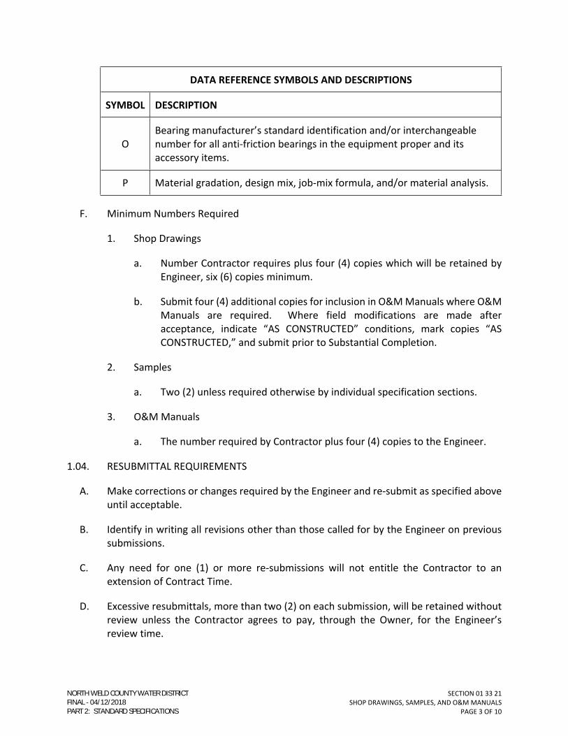
SECTION 01 33 21
SHOP DRAWINGS, SAMPLES, AND O&M MANUALS
PAGE 3 OF 10
DATA REFERENCE SYMBOLS AND DESCRIPTIONS
SYMBOL DESCRIPTION
O
Bearing manufacturer’s standard identification and/or interchangeable
number for all anti-friction bearings in the equipment proper and its
accessory items.
P Material gradation, design mix, job-mix formula, and/or material analysis.
F. Minimum Numbers Required
1. Shop Drawings
a. Number Contractor requires plus four (4) copies which will be retained by
Engineer, six (6) copies minimum.
b. Submit four (4) additional copies for inclusion in O&M Manuals where O&M
Manuals are required. Where field modifications are made after
acceptance, indicate “AS CONSTRUCTED” conditions, mark copies “AS
CONSTRUCTED,” and submit prior to Substantial Completion.
2. Samples
a. Two (2) unless required otherwise by individual specification sections.
3. O&M Manuals
a. The number required by Contractor plus four (4) copies to the Engineer.
1.04. RESUBMITTAL REQUIREMENTS
A. Make corrections or changes required by the Engineer and re-submit as specified above
until acceptable.
B. Identify in writing all revisions other than those called for by the Engineer on previous
submissions.
C. Any need for one (1) or more re-submissions will not entitle the Contractor to an
extension of Contract Time.
D. Excessive resubmittals, more than two (2) on each submission, will be retained without
review unless the Contractor agrees to pay, through the Owner, for the Engineer’s
review time.
NORTH WELD COUNTY WATER DISTRICTFINAL 04/12/2018PART 2: STANDARD SPECIFICATIONS
SECTION 01 33 21
SHOP DRAWINGS, SAMPLES, AND O&M MANUALS
PAGE 4 OF 10
1.05. SHOP DRAWINGS
A. Include the following pertinent information for each submittal:
1. Field dimensions, clearly identified as such.
2. Applicable standards, such as ASTM or Federal Specification numbers.
3. Motors - include the following:
a. Horsepower.
b. Voltage.
c. Temperature rating.
d. Service factor.
e. Full load current.
f. Full load rotative speed.
g. Power factor at full load.
h. Efficiency at full load.
i. Code letter.
j. Design letter.
4. Color charts and similar items.
5. All pertinent information required by each Section for each submittal shall be
highlighted in yellow and or circled with a cloud outline.
B. Manufacturer’s standard drawings, schematics, and diagrams.
1. Clearly mark each copy to identify pertinent products and models and to describe
exactly which parts of the Drawings apply to the equipment being furnished.
2. Delete information not applicable to the Work.
C. Reproductions or copies of portions of Contract Documents are not acceptable as
complete fabrication or erection drawings. However, they may be used as a drawing
upon which to indicate information on erection or to identify detail drawings.
D. Format
NORTH WELD COUNTY WATER DISTRICTFINAL 04/12/2018PART 2: STANDARD SPECIFICATIONS
SECTION 01 33 21
SHOP DRAWINGS, SAMPLES, AND O&M MANUALS
PAGE 5 OF 10
1. When practical, electronic format is preferred.
2. Minimum sheet size: 8-1/2” x 11”.
3. Maximum sheet size: 24” x 36”.
4. Cover Sheet shall delineate:
a. Date of submission.
b. Project title and number.
c. Name of Contractor, supplier, and manufacturers.
d. Specification Section number, intended use of item in the Work, and
equipment designation.
e. Identify details by reference to sheet, detail, schedule, or room numbers
shown in the Contract Documents.
f. Deviations from Contract Documents.
g. Revisions on re-submittals.
h. Contractor’s stamp, initialed or signed, certifying to review of submittal,
verification of products, field measurements and field construction criteria,
and coordination of the information within the submittal with requirements
of the Work and the Contract Documents.
i. Provide a clear space approximately three and one-half inches by two and
one-half inches (3-1/2” x 2-1/2”) for Engineer’s stamp on front page of
submittal.
j. Submittals shall be numbered sequentially. The submittal numbers shall be
clearly noted on the transmittal cover sheet. Original submittals shall begin
with the specification number followed by a hyphen and an alphanumeric
sequencing number. Resubmittals shall bear the number of the
alphanumeric system of the original submittal followed by the subsequent
letter of the alphabet to represent that it is a subsequent submittal of the
original.
(1) For example, if Submittal 330522-01A (the original submittal for
ductile iron pipe) requires a resubmittal, the first resubmittal will bear
the designation 330522-01B; the second resubmittal will bear the
designation 330522-01C, and so on.
NORTH WELD COUNTY WATER DISTRICTFINAL 04/12/2018PART 2: STANDARD SPECIFICATIONS

SECTION 01 33 21
SHOP DRAWINGS, SAMPLES, AND O&M MANUALS
PAGE 6 OF 10
1.06. SAMPLES
A. Samples shall be of sufficient size and quantity to clearly illustrate the functional
characteristics of the product with integrally-related parts and attachment devices and
the full range of color, texture, and pattern.
1.07. O&M MANUALS
A. Submit draft O&M Manuals by the time the Work is fifty percent (50%) complete for all
equipment so designated in the individual Sections and for which the Shop Drawings
were reviewed and marked “NO EXCEPTIONS TAKEN” or “MAKE CORRECTIONS NOTED.”
In addition, submit instruction books and other pertinent information for equipment not
so designated which required special instruction or knowledge for proper operation and
maintenance.
B. Submit final O&M Manual for equipment by the time Work is ninety percent (90%)
complete.
C. Do not start or operate equipment until the respective operation and maintenance data
has been reviewed, approved, and copies are made available at the site.
The O&M Manuals shall be in addition to instructions or parts lists packed with or
attached to equipment when delivered.
D. Include (as a minimum) the following information:
1. Equipment function, normal operating characteristics and limiting conditions,
complete motor data, test data, and performance curves where applicable.
2. Operating instructions for start-up, routine and normal operations, regulations
and control, shutdown, and emergency conditions.
3. Lubrication and routine maintenance instructions.
4. Guide to “troubleshooting.”
5. Parts lists, predicted life of parts subject to wear, and recommended list of spare
parts to be on hand.
6. Outline, cross-section, and assembly drawings, Engineering data, and wiring
diagrams.
7. Copy of accepted or as constructed Shop Drawings.
8. Temperature control diagrams.
NORTH WELD COUNTY WATER DISTRICTFINAL 04/12/2018PART 2: STANDARD SPECIFICATIONS
SECTION 01 33 21
SHOP DRAWINGS, SAMPLES, AND O&M MANUALS
PAGE 7 OF 10
9. System balance report including a description of system operation as prepared by
the balancing Contractor, which includes a schedule of inspection and
maintenance.
10. System schematic flow diagrams.
E. Format
1. Submit in a format suitable for binding in a three-ring binder or a post binder.
2. Minimum sheet size: Eight and one-half inches by eleven inches (8-1/2” x 11”).
3. Fold drawings larger than eleven inches by seventeen inches (11” x 17”) and insert
into individual pockets bound into the manuals.
4. Enclose pages subject to frequent usage by operators in clear plastic.
5. Individually annotate standard drawings that are furnished and describe exactly
which parts of the drawing apply to the equipment being furnished.
6. Identify each submission with the following:
a. Date of submission.
b. Project title and number.
c. Names of Contractor, supplier, and manufacturers (include telephone
numbers, addresses, and email addresses).
d. Names of subcontractors (with telephone numbers, addresses, and email
addresses), contracted by Contractor for servicing and maintenance of
portions of the project.
e. Specification Section number, intended uses of item in the Work, and
equipment designation.
f. Identify details by reference to sheet detail, schedule, or room numbers
shown in the Contract Documents.
g. Submitted number consistent with Paragraph 1.05.D.4.j of this Section.
1.08. REVIEW OF SUBMITTALS
A. A minimum of fourteen (14) days will be required for the Engineer to review each
submittal or re-submittal following the receipt of said submittal in the Engineer’s office
of all information required for review of the submittal. The Engineer will notify the
Contractor when the review time must be extended in order to correlate the submittal
NORTH WELD COUNTY WATER DISTRICTFINAL 04/12/2018PART 2: STANDARD SPECIFICATIONS

SECTION 01 33 21
SHOP DRAWINGS, SAMPLES, AND O&M MANUALS
PAGE 8 OF 10
with other forthcoming submittals or for any other reason that prevents the Engineer’s
timely review.
B. The Engineer will review submittals, affix a stamp and initials or signature, will indicate
subsequent action to be taken, and will return the submittals to the Contractor for
distribution. The review actions listed on the Engineer’s stamp or Cover Sheet are
defined as follows:
1. NO EXCEPTION TAKEN - Signified material or equipment represented by the
submittal conforms with the design concept and complies with the information
given in the Contract Documents. Contractor is to proceed with fabrication or
procurement of the items and with related work.
2. MAKE CORRECTIONS NOTED - Signified material or equipment represented by the
submittal conforms with the design concept and complies with the information
given in the Contract Documents and in accordance with the Engineer’s notations.
Contractor is to proceed with the Work in accordance with the Engineer’s
notations.
3. REVISE AND RESUBMIT - Signified material or equipment represented by the
submittal conforms with the basic design concept; however, it does not comply
with the information given in the Contract Documents. Contractor is to submit a
revised submittal responsive to the notations marked on the returned submittal
and to the information in the Contract Documents.
4. REJECTED - Signifies material or equipment represented by the submittal does not
conform with the design concept to comply with the information given in the
Contract Documents and is not acceptable for use in the Work. Contractor is to
submit material or equipment responsive to the Contract Documents.
5. SUBMIT SPECIFIED ITEM - Signifies material or equipment represented by the
submittal is not the item specified in the Contract Documents and is not to be
incorporated into the Work. Contractor is to submit only the material or
equipment specified in the Contract Documents.
C. The Engineer will return the number of copies of submittals specified below depending
on the action taken.
NORTH WELD COUNTY WATER DISTRICTFINAL 04/12/2018PART 2: STANDARD SPECIFICATIONS

SECTION 01 33 21
SHOP DRAWINGS, SAMPLES, AND O&M MANUALS
PAGE 9 OF 10
Action by Engineer
No. Retained
by Engineer
No. Returned
to Contractor
No. Required for
Re-submittal
No Exception Taken 4 2 or more 0
Make Corrections Noted 4 2 or more 0
Revise & Resubmit 4 2 or more 6 or more
Rejected 4 2 or more 6 or more
Submit Specified Item* 4 2 or more 6 or more
*Only one (1) copy of the submittals returned to the Contractor marked with these actions will be
stamped annotated.
1.09. DISTRIBUTION
A. Distribute reproduction or copies of Shop Drawings that carry the Engineer’s stamp of
acceptance to the Contractor’s personnel, the job site file, the project record document
file, the subcontractors, the suppliers, the manufacturers, and other affected
Contractors.
B. Distribute samples which carry the Engineer’s stamp of acceptance to the project record
file and the affected supplier or manufacturer.
C. The Engineer will distribute reviewed copies of Shop Drawings to NWCWD.
PART 2 - MATERIALS
(NOT USED)
PART 3 - EXECUTION
(NOT USED)
END OF SECTION
NORTH WELD COUNTY WATER DISTRICTFINAL 04/12/2018PART 2: STANDARD SPECIFICATIONS

SECTION 01 33 21
SHOP DRAWINGS, SAMPLES, AND O&M MANUALS
PAGE 10 OF 10
(THIS PAGE INTENTIONALLY LEFT BLANK)
NORTH WELD COUNTY WATER DISTRICTFINAL 04/12/2018PART 2: STANDARD SPECIFICATIONS
SECTION 01 45 00
QUALITY CONTROL
PAGE 1 OF 2
SECTION 01 45 00
QUALITY CONTROL
PART 1 – GENERAL
1.01. FORMER SECTION NUMBER(S): 01400.
1.02. DESCRIPTION
A. This Section covers the responsibilities for project staking and for performing the tests
required by these Standard Specifications.
1.03. CONSTRUCTION STAKE OUT
A. General
1. Contractor, using qualified, competent personnel, shall provide construction
stakes.
2. Engineer will establish base line or grid corners for horizontal control, and
temporary benchmarks for vertical control.
3. The grade and alignment shall be maintained by the use of suitable surveying
instruments or laser equipment operated continuously during construction.
B. Grade Stakes
1. Waterlines shall be staked on the centerlines of the waterlines, at all fittings and
angle points, and any other points necessary for establishing the line. Cuts will be
established at all main fittings to ensure proper depth of the line. Fire hydrants
will be staked with a five-foot (5’-0”) offset.
C. Survey Notes
1. Enter all survey notes and construction stakeout (cut) notes into bound, hardcover
field books.
2. All survey data developed by the Contractor in performing the Work shall be
available throughout the construction period and shall be provided as part of the
Record Drawings.
1.04. TESTS AND INSPECTIONS
A. Coordinate with NWCWD before backfilling of any waterline of services for inspection
and survey.
NORTH WELD COUNTY WATER DISTRICTFINAL 04/12/2018PART 2: STANDARD SPECIFICATIONS

SECTION 01 45 00
QUALITY CONTROL
PAGE 2 OF 2
B. NWCWD requires every joint, fitting, tap, etc. to be inspected and surveyed by NWCWD
personnel.
C. The Contractor shall employ and pay for the services of a qualified independent testing
laboratory to conduct the tests to determine compliance with the Specifications from
the following:
1. Soil compaction control as specified in Section 31 23 35 -– TRENCHING,
BACKFILLING, AND COMPACTING.
D. Contractor shall conduct the following tests under the observation of, and to the
satisfaction of, the Engineer:
1. Pressure and leakage tests as specified in Section 33 05 06 – TESTING PIPING
SYSTEM.
2. Bacteriologic tests as specified in Section 33 01 11 – DISINFECTION OF DOMESTIC
WATERLINES.
E. The Contractor shall pay for retest(s) of items which fail to pass initial tests specified
above, as well as for all tests the Contractor requires for control of his own construction
operations.
PART 2 - MATERIALS
(NOT USED)
PART 3 - EXECUTION
(NOT USED)
END OF SECTION
NORTH WELD COUNTY WATER DISTRICTFINAL 04/12/2018PART 2: STANDARD SPECIFICATIONS

SECTION 01 50 00
CONSTRUCTION FACILITIES AND TEMPORARY CONTROLS
PAGE 1 OF 4
SECTION 01 50 00
CONSTRUCTION FACILITIES AND TEMPORARY CONTROLS
PART 1 - GENERAL
1.01. FORMER SECTION NUMBER(S): 01500.
1.02. TEMPORARY UTILITIES
A. Construction Water
1. Coordinate construction water sources with NWCWD. NWCWD will install meter
and cross-connection control, as required.
1.03. TEMPORARY CONTROLS
A. Noise Control
1. Equip construction machinery and vehicles with practical sound and muffling
devices and operate in a manner to minimize noise consistent with efficient
performance of the Work.
B. Dust Control
1. Take reasonable measures to prevent unnecessary dust.
2. Moisten dirt roads used for transportation and haul with water or apply a chemical
dust suppressant to control dust.
3. Cover dusty material in transit when necessary to prevent blowing.
C. Pollution Control
1. Prevent the pollution of drains and water courses by sanitary wastes, sediment,
debris, and other substances resulting from construction activities.
2. Retain all spent oils, hydraulic fluids, and other petroleum fluids in containers for
disposal off the site.
3. Do not perform equipment maintenance or fueling within fifty feet (50’) of any
water course.
D. Erosion Control
NORTH WELD COUNTY WATER DISTRICTFINAL 04/12/2018PART 2: STANDARD SPECIFICATIONS

SECTION 01 50 00
CONSTRUCTION FACILITIES AND TEMPORARY CONTROLS
PAGE 2 OF 4
1. Take such measures as are necessary to prevent erosion of soil on the site and
adjacent properties that might result from construction activities.
2. Provide temporary materials such as hay bales, sand bags, plastic sheets, chain
link fencing fabric, rip-rap, or culverts to prevent the erosion of banks or
excavation where runoff may be increased or concentrated due to construction
activities.
3. Comply with the local jurisdiction’s erosion control program.
1.04. TRAFFIC REGULATION
A. Keep traffic areas free of excavated material, construction equipment, pipe, and other
materials and equipment, unless otherwise stipulated, and conduct operations in a
manner to avoid unnecessary interference with public and roads.
B. Furnish properly equipped flagmen where necessary to provide for public safety, or
where required by jurisdictional authorities.
C. Warning Signs and Lights
1. Provide barricades and warning signs for open excavations, parked equipment,
and soil stockpiles.
2. Illuminate by means of warning lights all barricades and obstructions from sunset
to sunrise.
3. Comply with “Manual on Uniform Traffic Control Devices,” U.S. Dept. of
Transportation, or applicable statutory requirements of State Highway
Department, e.g. CDOT.
D. Provide suitable parking areas for the use of all construction workers and others
performing work in furnishing services in connection with the Project so as to avoid
interference with construction activities.
1.05. PROJECT IDENTIFICATION AND SIGNS
(NOT USED)
1.06. FIELD OFFICES
(NOT USED)
PART 2 - MATERIALS
(NOT USED)
NORTH WELD COUNTY WATER DISTRICTFINAL 04/12/2018PART 2: STANDARD SPECIFICATIONS

SECTION 01 50 00
CONSTRUCTION FACILITIES AND TEMPORARY CONTROLS
PAGE 3 OF 4
PART 3 - EXECUTION
(NOT USED)
END OF SECTION
NORTH WELD COUNTY WATER DISTRICTFINAL 04/12/2018PART 2: STANDARD SPECIFICATIONS

SECTION 01 50 00
CONSTRUCTION FACILITIES AND TEMPORARY CONTROLS
PAGE 4 OF 4
(THIS PAGE INTENTIONALLY LEFT BLANK)
NORTH WELD COUNTY WATER DISTRICTFINAL 04/12/2018PART 2: STANDARD SPECIFICATIONS

SECTION 01 60 10
MATERIALS, EQUIPMENT, AND WORKMANSHIP
PAGE 1 OF 4
SECTION 01 60 10
MATERIALS, EQUIPMENT, AND WORKMANSHIP
PART 1 - GENERAL
1.01. FORMER SECTION NUMBER(S): 01600; MS-APPENDIX.
1.02. MATERIALS AND EQUIPMENT
A. Contractor shall furnish all materials, equipment, labor, and all other facilities and
incidentals necessary for the execution, disinfection, testing, and completion of the
Work, with the exception of any such items furnished by NWCWD.
1. Reference Section 01 11 00 – SUMMARY OF WORK.
B. All materials and equipment shall be of good quality and new, except as otherwise
provided in these Specifications.
1. When requested by NWCWD, the Contractor shall furnish satisfactory evidence
(including manufacturer's certification) as to the kind and quality of materials and
equipment, and their compliance with these Specifications.
a. NWCWD shall test any manufacturer's material it deems necessary.
b. It is the Contractor's responsibility to ensure the manufacturer's materials
meet these Specifications.
C. All materials and equipment shall be installed and used in accordance with the
instructions of the applicable manufacturer, fabricator, supplier or distributor, except as
otherwise provided in these Specifications.
D. The specification of materials and equipment shall be understood to be representative
of a quality of performance, operation, and construction acceptable to NWCWD.
1. NWCWD may evaluate all written requests for product substitution.
a. Refer to Paragraph 1.03 of this Section for procedures.
E. In approving materials or equipment for installation, NWCWD assumes no responsibility
for injury or claims resulting from failure of the materials or equipment to comply with
applicable National, State, and local safety codes or requirements, or the safety
requirements of a recognized agency; or failure due to faulty design concepts, or
defective workmanship.
NORTH WELD COUNTY WATER DISTRICTFINAL 04/12/2018PART 2: STANDARD SPECIFICATIONS

SECTION 01 60 10
MATERIALS, EQUIPMENT, AND WORKMANSHIP
PAGE 2 OF 4
1.03. PROCEDURE FOR EVALUATION OF MATERIALS
A. GENERAL
1. New products or materials related to the water industry may be evaluated by
NWCWD. Sales representatives may petition for consideration and evaluation
under the procedures of this Section.
B. REVIEW COMMITTEE
1. Initial application for consideration shall be made by contacting the NWCWD’s
District Engineer. If determined appropriate, the evaluation of products and
materials shall be made by an ad hoc committee called by NWCWD’s District
Engineer or appointed representative.
2. The committee shall be composed of two or more NWCWD employees. NWCWD’s
Construction Manager will act as chairman and the remaining committee
members shall reflect NWCWD’s divisions affected by the proposed products.
C. EVALUATION
1. The review committee will give careful consideration to the products based upon
their collective experience and opinions. They will assure themselves that proper
criteria exists or they will develop criteria by which the products can be
evaluated. They will seek out other knowledgeable persons both inside and
outside of NWCWD and attempt to determine by this means whether the product
falls clearly into one of the following Categories:
a. Acceptable;
b. Not acceptable; or
c. Borderline
2. Should the product be found in Category a or b, the committee will advise
NWCWD’s District Engineer or appointed representative who will, in-turn, advise
the sales representative in writing of the findings. Should the product fall under
the Category c (Borderline), the committee chairman will contact the sales
representative for additional data, for product samples, and arrange for testing.
D. TESTING
1. If the product has some promise, but is not clearly acceptable, a testing program
may be undertaken with the concurrence of the sales representative. The review
committee will arrange actual field testing procedures.
NORTH WELD COUNTY WATER DISTRICTFINAL 04/12/2018PART 2: STANDARD SPECIFICATIONS

SECTION 01 60 10
MATERIALS, EQUIPMENT, AND WORKMANSHIP
PAGE 3 OF 4
2. The sales representative shall furnish samples to be tested, any special test
equipment not already available to the review committee, any necessary
appurtenant materials, pipe, gauges, charts, recording equipment, and, when
necessary, a location to conduct the tests. In some instances, testing may consist
of trial installations into NWCWD’s distribution system. Determination of the
nature of the testing shall rest with NWCWD. NWCWD reserves the right to
require full reimbursement for test and evaluation expense.
3. Testing shall be undertaken with the object of clearly determining the
acceptability of the product. For some products where durability is in question,
the test period may necessarily last for several years. NWCWD's goal will be to
make an adequate determination within the minimum necessary time. Following
completion of tests, the committee will meet with the sales representative to
discuss results and any further testing or consideration. The committee will then
meet with NWCWD’s Engineer or appointed representative to discuss the product
and to reach a decision.
E. NOTIFICATION
1. NWCWD’s Engineer or appointed representative will notify the sales
representative in writing of his/her decision to either accept the product and
include it into NWCWD’s Standard Specifications or to reject the product as not
acceptable.
F. APPEAL
1. If the product is rejected and if the sales representative has good reason to feel
that his/her product did not receive an adequate or fair test, he/she may appeal
in writing to NWCWD’s District Engineer. The sales representative shall fully
document his/her allegations and ask for reconsideration based upon new facts,
testing, late results, or some such factual basis. If NWCWD’s Engineer finds
reason for further consideration, he/she will arrange for another meeting
including himself/herself, the sales representative, NWCWD’s District Engineer or
appointed representative and any other NWCWD employee who might
contribute, to consider further testing of evaluation. A subsequent final decision
will then be rendered in writing under the signature of NWCWD’s District Engineer
or appointed representative.
2. If NWCWD’s District Engineer does not find sufficient cause to further investigate
the matter, he/she shall advise the sales representative in writing, and that
decision shall be final.
G. LIMITATION ON REAPPLICATION
NORTH WELD COUNTY WATER DISTRICTFINAL 04/12/2018PART 2: STANDARD SPECIFICATIONS

SECTION 01 60 10
MATERIALS, EQUIPMENT, AND WORKMANSHIP
PAGE 4 OF 4
1. If, after a product is rejected, significant changes are incorporated into its
manufacture such as would render it now acceptable, the sales representative
may reapply to NWCWD’s District Engineer or appointed representative for
reconsideration. In the absence of changed conditions, the product will not be
reconsidered for inclusion into the Standard Specifications for a period of three
years after having been rejected.
1.04. WORKMANSHIP
A. Contractor shall provide competent, disciplined, suitably qualified personnel to lay out
the Work and perform the construction.
B. The construction standards, tests, and methods outlined in these Specifications are
considered adequate to produce the product desired by NWCWD.
1. NWCWD may evaluate alternative methods of construction upon written request.
a. Requests for alternative methods of construction shall include detailed
descriptions of the equipment, methods and controls needed for the
alternative, and a description of the benefits which might be achieved by
this substitution.
PART 2 - MATERIALS
(NOT USED)
PART 3 - EXECUTION
(NOT USED)
END OF SECTION
NORTH WELD COUNTY WATER DISTRICTFINAL 04/12/2018PART 2: STANDARD SPECIFICATIONS

SECTION 01 74 11
SITE CLEANUP
PAGE 1 OF 2
SECTION 01 74 11
SITE CLEANUP
PART 1 - GENERAL
1.01. FORMER SECTION NUMBER(S): 01710.
1.02. GENERAL
A. Site cleanup shall be executed during the progress of the work, and at the completion
of the work.
PART 2 - MATERIALS
(NOT USED)
PART 3 - EXECUTION
3.01. GENERAL
A. Construction materials shall be neatly stored.
B. Containers shall be provided for the collection of waste material and debris.
1. Containers shall be stored out of the right-of-way.
C. Volatile wastes shall be stored in clearly marked, covered metal containers and removed
daily.
D. Construction material, equipment, waste containers, construction buildings, parking
etc., shall only be allowed within the limits of the construction easement.
1. Any off-site storage of construction material, equipment, waste containers,
construction buildings, parking, etc. shall be allowed only after the Contractor has
obtained the written permission from the property owner.
E. Upon completion of the construction, the job site shall be restored to its original
condition.
1. Contractor shall restore any land that will not be paved with asphalt, or concrete,
to its original condition.
a. All topsoil shall be restored to its original quality.
NORTH WELD COUNTY WATER DISTRICTFINAL 04/12/2018PART 2: STANDARD SPECIFICATIONS

SECTION 01 74 11
SITE CLEANUP
PAGE 2 OF 2
b. Any areas which are stripped of vegetation prior to or during construction
shall be reseeded.
2. All exterior paved surfaces shall be broom cleaned, and left in good repair.
3.02. DISPOSAL
A. In order to maintain an orderly site, waste material and debris shall be removed
periodically.
B. Volatile wastes shall be removed daily.
END OF SECTION
NORTH WELD COUNTY WATER DISTRICTFINAL 04/12/2018PART 2: STANDARD SPECIFICATIONS

SECTION 01 78 41
PROJECT RECORD DRAWINGS
PAGE 1 OF 2
SECTION 01 78 41
PROJECT RECORD DRAWINGS
PART 1 - GENERAL
1.01. FORMER SECTION NUMBER(S): 01720.
1.02. RECORDING OF DRAWINGS
A. Accurate Project Record Drawings shall be compiled by the Contractor and by the Design
Engineer, and shall be submitted to NWCWD, for review, prior to Conditional
Acceptance of the Work.
B. Each sheet of the Drawings shall be labeled "DRAWINGS OF RECORD" in neat large
printed letters.
C. Construction information shall be recorded concurrently with construction progress.
D. Project Record Drawings shall be marked legibly and with an indelible pen.
E. Project Record Drawings shall record actual construction and contain the following:
1. Field dimensions, elevations, and details.
2. Changes which are made by a modification. Reference the change authorization,
e.g., RFI response, work change directive, etc.
3. Details which are not on the original Construction Drawings.
4. Horizontal and vertical locations of underground utilities and appurtenances
referenced to a minimum of three permanent surface improvements.
5. Depths of various elements of work in relation to project datum.
1.03. MAINTENANCE OF PROJECT RECORD DRAWINGS DURING CONSTRUCTION
A. Project Record Drawings shall be stored apart from documents used for construction.
B. Project Record Drawings shall be maintained in a clean, dry, legible condition and in
good order.
1. Project Record Drawings and any documents used for the preparation of said
Drawings shall not be used for construction purposes.
NORTH WELD COUNTY WATER DISTRICTFINAL 04/12/2018PART 2: STANDARD SPECIFICATIONS

SECTION 01 78 41
PROJECT RECORD DRAWINGS
PAGE 2 OF 2
1.04. SUBMISSION
A. Project Record Drawings shall be submitted to NWCWD with a transmittal letter, in
duplicate, containing:
1. Date.
2. Project title.
3. Contractor's name, address, telephone number, email address, and website.
4. Developer's name, address, telephone number, email address, and website.
5. Title and number of each Record Document.
B. Project Record Drawings shall be submitted on 22" x 34", 3 mil (minimum) reproducible,
double-matte Mylar.
1. Coordinate system shall be Colorado 501 North - NAD 83 and NAVD 83, Geo Model
9-US.
2. No acceptance of the utility lines will be made until the Project Record Drawings
are received and accepted by NWCWD.
C. Provide submittals in accordance with Section 01 33 21 – SHOP DRAWINGS, SAMPLES,
AND O&M MANUALS.
PART 2 - MATERIALS
(NOT USED)
PART 3 - EXECUTION
(NOT USED)
END OF SECTION
NORTH WELD COUNTY WATER DISTRICTFINAL 04/12/2018PART 2: STANDARD SPECIFICATIONS

SECTION 03 30 10
CAST-IN-PLACE CONCRETE (SMALL VOLUME)
PAGE 1 OF 24
SECTION 03 30 10
CAST-IN-PLACE CONCRETE (SMALL VOLUME)
PART 1 - GENERAL
1.01. FORMER SECTION NUMBER(S): 03300S.
1.02. DESCRIPTION
A. This Section covers cast-in-place concrete; including forms, reinforcing steel, materials,
transporting, placing, finishing, curing, and other appurtenant items of construction.
B. Inform the Engineer at least forty-eight (48) hours in advance of the times and places at
which Contractor intends to place concrete.
1.03. QUALITY ASSURANCE
A. Perform all work as specified herein and in accordance with the latest revisions of the
following codes and standards:
1. Federal, state, and local codes, regulations, and standards.
2. American Society for Testing and Materials, (ASTM).
B. Reference Standards
1. Except as noted or modified in this Section, all concrete materials, transporting,
placing, finishing, and curing shall conform to the requirements of the following
standard specifications:
a. American Concrete Institute Standards (ACI)
(1) 117– Standard Specifications for Tolerances for Concrete Construction
and Materials.
(2) 301 – Specifications for Structural Concrete.
(3) 304 – Guide for Measuring, Mixing, Transporting, and Placing
Concrete.
(4) 305 – Hot Weather Concreting.
(5) 306 – Cold Weather Concreting.
(6) 309 – Guide for Consolidation of Concrete.
NORTH WELD COUNTY WATER DISTRICTFINAL 04/12/2018PART 2: STANDARD SPECIFICATIONS

SECTION 03 30 10
CAST-IN-PLACE CONCRETE (SMALL VOLUME)
PAGE 2 OF 24
(7) 315 – Details and Detailing of Concrete Reinforcement.
(8) 318 – Building Code Requirements for Reinforced Concrete.
(9) 347 – Recommended Practice for Concrete Formwork.
C. In case of conflict or disagreement between codes, standards, laws, ordinances, rules
and regulations, or within any document itself, the more stringent requirements as
determined by the Engineer shall govern.
1. Where Work required by the Drawings and Specifications is above the standard
required by local regulations or recommended standards, it shall be completed as
shown and/ or specified.
1.04. SUBMITTALS
A. Provide submittal’s in accordance with Section 01 33 21 – SHOP DRAWINGS, SAMPLES,
AND O&M MANUALS.
B. Test Results
1. Perform and submit test reports for the following products in accordance with the
above general reference standards and specific standards of these Specifications.
C. Proposed Mix Design
1. Prior to commencing concrete work, submit certified test reports describing
proposed concrete mix design, including:
a. Fine aggregate - Source, type, gradation, deleterious substances, and bulk-
specific gravity on the basis of weight of saturated surface - dry aggregate
(ASTM C 128).
b. Coarse aggregate - Source, type, gradation, deleterious substances, and bulk-
specific gravity on the basis of weight of saturated surface - dry aggregate
(ASTM C 217).
c. Reactive aggregate test reports (ASTM C 1260).
d. Ratio of fine to total aggregates.
e. Weight (surface dry) of each aggregate per cubic yard.
f. Total water content in gallons per cubic yard and proposed source.
g. Slump on which the mix design is based.
NORTH WELD COUNTY WATER DISTRICTFINAL 04/12/2018PART 2: STANDARD SPECIFICATIONS
SECTION 03 30 10
CAST-IN-PLACE CONCRETE (SMALL VOLUME)
PAGE 3 OF 24
h. Brand, type, and quantity of cement.
i. Brand, type, and quantity of admixtures.
j. Air content.
k. Two (2) sets of compression test cylinders (two (2) cylinders per set) shall be
made for each proposed mix design.
(1) Test one (1) set of two (2) cylinders at age seven (7) days and other
set at twenty-eight (28) days.
D. Cylinder Compression Test Reports
1. Submit two (2) copies of certified test reports to the Engineer.
E. Ready-Mix Delivery Tickets
1. Submit delivery tickets for each load at the time of delivery indicating the
following:
a. Quantity delivered.
b. Quantity of each material in batch.
c. Amount of water that may be added on site.
d. Outdoor temperature in shade.
e. Time at which water was added.
f. Elapsed time between when water was added and when concrete load was in
place.
g. Amounts of initial and supplemental water added.
h. Name of individual authorizing supplemental water.
i. Numerical sequence of delivery by indicating cumulative yardage delivered on
each ticket.
F. Shop Drawings
1. Show sizes, quantity, and dimensions for fabrication and placing of reinforcing
bars, bar supports, and embedments.
2. Indicate bar schedules, stirrup and tie spacing, and diagrams of bent bars.
NORTH WELD COUNTY WATER DISTRICTFINAL 04/12/2018PART 2: STANDARD SPECIFICATIONS

SECTION 03 30 10
CAST-IN-PLACE CONCRETE (SMALL VOLUME)
PAGE 4 OF 24
3. Show locations and sizes of openings, penetrations, and embedments.
1.05. PRODUCT DELIVERY, STORAGE, AND HANDLING
A. Cement
1. Store in weather-tight enclosures and protect against dampness, contamination,
and warehouse set.
2. Do not use cement that has become caked or lumpy.
B. Aggregates
1. Stockpile to prevent excessive segregation or contamination with other sizes of
aggregates.
2. Use only one (1) supply source for each aggregate stockpile.
3. The bottom six inches (6”) of all aggregate piles in contact with the ground shall
not be used.
C. Admixtures
1. Store to prevent contamination, evaporation, or damage.
2. Protect liquid admixtures from freezing or harmful temperature ranges.
3. Agitate emulsions before use.
D. Mixing and Transporting Ready-Mixed Concrete.
1. Maximum elapsed time from time water is added to mix until concrete is in place
shall not exceed one and one-half (1-1/2) hours when concrete is transported in
revolving-drum truck bodies.
E. Reinforcing Steel.
1. Deliver to site in bundles marked with metal tags indicating bar size and length.
2. Carefully handle and store on supports that will keep the steel from coming in
contact with the ground.
1.06. JOB CONDITIONS
A. Environmental Requirements
NORTH WELD COUNTY WATER DISTRICTFINAL 04/12/2018PART 2: STANDARD SPECIFICATIONS

SECTION 03 30 10
CAST-IN-PLACE CONCRETE (SMALL VOLUME)
PAGE 5 OF 24
1. Do not place concrete during rain, sleet, or snow unless adequate protection is
provided.
2. Do not allow rainwater to increase mixing water or damage surface finish.
B. Cold Weather Concreting
1. Conform to ACI 306.
2. Temperature of concrete when placed shall not be less than following.
Air Temp. (°F.)
Sections with Least
Dimension Under Twelve
Inches (12”)
Sections with Least
Dimension Twelve Inches
(12”) and Over
30 to 45 60° F 50° F
0 to 30 65° F 55° F
Below 0 70° F 60° F
3. Heated concrete shall not be warmer than eighty degrees Fahrenheit (80°F) when
placed.
4. Prior to placing concrete, all ice, snow, and surface and subsurface frost shall be
removed.
a. The temperature of the surfaces to be in contact with the new concrete shall
be raised above thirty-five degrees Fahrenheit (35°F) for a minimum of
twenty-four (24) hours immediately prior to placing concrete.
5. Protect concrete from freezing during specified curing period.
a. Cold weather protection shall be maintained at a minimum temperature of
fifty degrees Fahrenheit (50°F) for a minimum of five (5) days.
6. Heated enclosures shall be strong and windproof to ensure adequate protection
of corners, edges, and thin sections.
7. Do not permit heating units to locally heat or dry the concrete.
8. Do not use combustion heaters during the first twenty-four (24) hours unless the
concrete is protected from exposure to exhaust gases that contain carbon dioxide.
C. Hot Weather Concreting
NORTH WELD COUNTY WATER DISTRICTFINAL 04/12/2018PART 2: STANDARD SPECIFICATIONS

SECTION 03 30 10
CAST-IN-PLACE CONCRETE (SMALL VOLUME)
PAGE 6 OF 24
1. Conform to ACI 305.
2. Take precautions when ambient air temperature is ninety degrees Fahrenheit (90°F)
or above.
3. Temperature of concrete, when placed, shall not exceed eighty-five degrees
Fahrenheit (85°F).
4. Cool forms and reinforcing to a maximum of ninety degrees Fahrenheit (90°F) by
spraying with water before placing concrete.
5. Do not use cement that has reached a temperature of one hundred seventy
degrees Fahrenheit (170°F) or more.
6. Prevent plastic shrinkage and cracking due to rapid evaporation of moisture.
7. Do not place concrete when evaporation rate (actual or anticipated) equals or
exceeds specified limits in ACI 305.
8. Set-retarding and water-reducing admixtures may only be used with Engineer’s
concurrence.
PART 2 - MATERIALS
2.01. CONCRETE
A. Cement
1. ASTM C 150, Type I/II or Type II, sulfate resistant.
2. Tricalcium Aluminate (C3A) in the Type II cements shall not exceed eight percent
(8%).
B. Aggregates
1. Aggregates shall not be potentially alkali-silica reactive as defined in Appendix X1
of ASTM C33, unless otherwise approved by the Engineer.
2. Fine aggregate: ASTM C 33.
3. Coarse aggregate: ASTM C 33.
a. Air-cooled blast furnace slag will not be allowed.
b. Nominal maximum size of coarse aggregate shall conform to ACI 318.
NORTH WELD COUNTY WATER DISTRICTFINAL 04/12/2018PART 2: STANDARD SPECIFICATIONS

SECTION 03 30 10
CAST-IN-PLACE CONCRETE (SMALL VOLUME)
PAGE 7 OF 24
C. Water
1. Shall be clean, fresh, and free from injurious amounts of oils, acids, alkalis, salts,
organic materials, or other substances that may be deleterious to concrete
reinforcement.
D. Admixtures
1. Do not use admixtures that cause accelerated setting of cement.
2. Calcium chloride is not permitted.
3. Air-entraining agent: ASTM C 260, nontoxic after thirty (30) days and containing
no chlorides.
4. Water-reducing and retarding: ASTM C 494, Type A or Type D.
a. May only be used with the Engineer’s concurrence.
5. Pozzolan (Fly Ash): Class F fly ash in accordance with ASTM C618, Tables 1 and 2,
except as modified herein:
a. Loss on Ignition: Maximum 3 percent (3%).
b. Water Requirement: Maximum 100 percent of control.
c. Available Alkalies: Maximum of one and one-half percent (1-1/2%) Na20
determined in accordance with ASTM C311 when any portion of aggregates
are potentially reactive as defined in Appendix X1 of ASTM C33.
d. ASTM C618, Table 3, Effectiveness in Controlling Alkali-Silica Reaction,
applies when any portion of aggregates are potentially reactive as defined
in Appendix X1 of ASTM C33.
e. ASTM C618, Table 2A, Uniformity Requirements, apply when loss on ignition
of fly ash furnished exceeds three percent (3%).
6. Superplasticizers: ASTM C 494.
a. Use in all structural walls and beams. Use in other elements and slabs at
Contractor’s option.
7. Waterproofing
a. Use waterproofing admixture where specified and shown on the Drawings.
b. Submit proposed admixture to the Engineer for review prior to use.
NORTH WELD COUNTY WATER DISTRICTFINAL 04/12/2018PART 2: STANDARD SPECIFICATIONS

SECTION 03 30 10
CAST-IN-PLACE CONCRETE (SMALL VOLUME)
PAGE 8 OF 24
2.02. FORM MATERIALS
1. General
a. Reference ACI 301.
b. Where “Smooth and Finish” or “Grout Cleaned Finish” is specified, use
prefabricated plywood panel forms, job-built plywood forms, forms lined
with plywood or fiberboard, or steel forms.
c. Where “Rough Form Finish” is specified, unlined wooden forms may be
used.
d. Lumber
(1) Straight, uniform width and thickness; free from knots, offsets, holes,
dents, and other surface defects.
(2) Chamfer Strips: Clean, white pine with the surface against concrete
planed.
2. Form Ties
a. Removable end, permanently-embedded body type, with cones on outer
ends.
(1) Provide form ties with center waterstop ring at locations where
surface water, ground water or hydrostatic conditions may be
encountered, as indicated on the drawing, or as directed by the
Engineer.
b. Sufficient strength and rigidity to support and maintain the form in proper
position and alignment without the use of auxiliary spreaders.
c. The permanently-embedded portion shall be recessed a minimum of one
inch (1”) from concrete surface.
3. Form Coating
a. Non-staining chemical release agent that will not damage the concrete
surface.
b. For all exposed surfaces not in contact with earth backfill, use:
(1) Symons Corporation, “Magic Kote”;
(2) Or approved equal.
NORTH WELD COUNTY WATER DISTRICTFINAL 04/12/2018PART 2: STANDARD SPECIFICATIONS

SECTION 03 30 10
CAST-IN-PLACE CONCRETE (SMALL VOLUME)
PAGE 9 OF 24
2.03. REINFORCEMENT MATERIAL
1. Rebar
a. Conform to ACI 315 and ACI 318.
b. Bars shall be Grade 60, unless indicated otherwise on the Drawings, ASTM
A 615.
c. Column spirals shall be cold-drawn wire, ASTM A 82.
d. Tie wire shall be annealed steel, sixteen (16) gauge minimum, ASTM A 510.
e. Bar Supports
(1) Where concrete surface will be exposed to weather, the portions of
the supports or accessories within one-half inch (1/2”) of the concrete
surface shall be non-corrosive or protected against corrosion (epoxy
covered).
(2) Plastic bar supports are not acceptable.
2. Welded Wire Fabric
a. Plain Wire: ASTM A 185.
b. Deformed Wire: ASTM A 497.
2.04. CONCRETE ACCESSORY MATERIALS
1. Curing Materials
a. Water.
b. Sheet material: ASTM C 171.
c. Liquid membrane: ASTM C 309.
2. Expansion Joint Filler
a. Bituminous type: ASTM D 994.
b. Cork type: ASTM D 1752, Type 2 or 3.
c. Fiber type: ASTM D 1751.
3. Bond Break Material
NORTH WELD COUNTY WATER DISTRICTFINAL 04/12/2018PART 2: STANDARD SPECIFICATIONS

SECTION 03 30 10
CAST-IN-PLACE CONCRETE (SMALL VOLUME)
PAGE 10 OF 24
a. Felt: ASTM D 2475.
b. Polyethylene sheet material.
4. Joint Sealers
a. Cold-application type: ASTM D 1850.
b. Hot-poured elastic type: ASTM D 1190.
c. Hydrostatic pressure resistant type sealant.
(1) Sikaflex 2C NS/SL;
(2) Or equal.
5. Waterstop
a. Material
(1) Polyvinyl chloride (PVC).
b. Type
(1) Construction joints: Ribbed with center bulb.
(2) Expansion joints: Ribbed with center bulb.
c. Manufacturer
(1) Greenstreak;
(2) Or equal.
d. Size
(1) Six inches (6”) wide, minimum.
(2) Three-eighths-inch (3/8”) thick, minimum.
e. Hydrophilic waterstop – where specifically noted on the Drawings.
(1) Greenstreak Hydrotite Type CJ-0725-3K, 0.28 inches high by 0.98
inches wide;
(2) Or equal.
6. Vapor Barrier Material
NORTH WELD COUNTY WATER DISTRICTFINAL 04/12/2018PART 2: STANDARD SPECIFICATIONS
SECTION 03 30 10
CAST-IN-PLACE CONCRETE (SMALL VOLUME)
PAGE 11 OF 24
a. Polyethylene sheet, 6 mil minimum thickness.
7. Curing Compound
a. Liquid membrane-forming.
b. Pigmented and non-pigmented ASTM C 309, VOC compliant.
(1) W.R. Meadows, VOCOMP-30.
(2) Or equal.
8. Non-Shrink Grout
a. Master Builders 713;
b. Sonogrout 14K;
c. Or equal.
9. Sealer
a. Where shown on the Drawings
(1) W.R. Meadows, VOCOMP-30;
(2) Or equal.
10. Crack Repair Epoxy
a. Two-component epoxy injection by Sika Chemical Corporation;
b. Or equal.
11. Anchor Epoxy
a. Hilti HIT RE 500 SD;
b. Or equal.
2.05. MIXES
(NOT USED)
2.06. FABRICATION AND MANUFACTURE
A. Concrete Production
NORTH WELD COUNTY WATER DISTRICTFINAL 04/12/2018PART 2: STANDARD SPECIFICATIONS
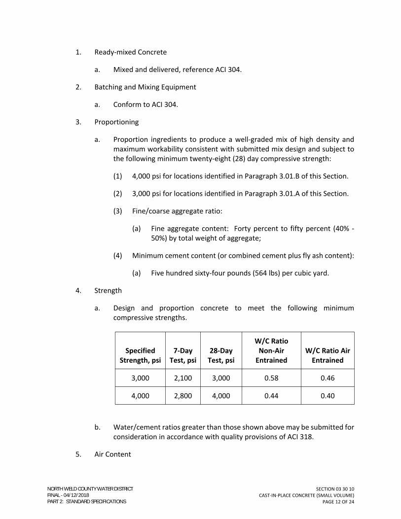
SECTION 03 30 10
CAST-IN-PLACE CONCRETE (SMALL VOLUME)
PAGE 12 OF 24
1. Ready-mixed Concrete
a. Mixed and delivered, reference ACI 304.
2. Batching and Mixing Equipment
a. Conform to ACI 304.
3. Proportioning
a. Proportion ingredients to produce a well-graded mix of high density and
maximum workability consistent with submitted mix design and subject to
the following minimum twenty-eight (28) day compressive strength:
(1) 4,000 psi for locations identified in Paragraph 3.01.B of this Section.
(2) 3,000 psi for locations identified in Paragraph 3.01.A of this Section.
(3) Fine/coarse aggregate ratio:
(a) Fine aggregate content: Forty percent to fifty percent (40% -
50%) by total weight of aggregate;
(4) Minimum cement content (or combined cement plus fly ash content):
(a) Five hundred sixty-four pounds (564 lbs) per cubic yard.
4. Strength
a. Design and proportion concrete to meet the following minimum
compressive strengths.
Specified
Strength, psi
7-Day
Test, psi
28-Day
Test, psi
W/C Ratio
Non-Air
Entrained
W/C Ratio Air
Entrained
3,000 2,100 3,000 0.58 0.46
4,000 2,800 4,000 0.44 0.40
b. Water/cement ratios greater than those shown above may be submitted for
consideration in accordance with quality provisions of ACI 318.
5. Air Content
NORTH WELD COUNTY WATER DISTRICTFINAL 04/12/2018PART 2: STANDARD SPECIFICATIONS

SECTION 03 30 10
CAST-IN-PLACE CONCRETE (SMALL VOLUME)
PAGE 13 OF 24
a. Minimum entrained air for concrete required to be watertight, including
concrete for all liquid-containing structures:
(1) Six percent plus or minus one percent (6% ± 1%) for three-quarter-inch
(3/4”) or one-inch (1”) coarse aggregate.
(2) Five percent plus or minus one percent (5% ± 1%) for one and one-
half-inch (1-1/2”) coarse aggregate.
b. Minimum entrained air for all other concrete:
(1) Six percent plus or minus one and one-half percent (6% ± 1.5%) for
three-quarter-inch (3/4”) coarse aggregate.
(2) Five percent plus or minus one and one-half percent (5% ± 1-1/2%) for
one and one-half-inch (1-1/2”) coarse aggregate.
(3) Refer to ACI 301 for further requirements.
6. Slump Range at Site
a. Nonsuperplasticized Concrete: Three inches (3”) minimum, five inches (5”)
maximum.
b. Superplasticized Concrete: Four and one-half inches (4-1/2”) minimum,
eight inches (8”) maximum.
c. Take design mix test cylinders from concrete with slump equal to that used
on Project at the point of discharge into the forms.
7. Mixing - Minimum time
a. Central-mixed concrete, one (1) minute for mixer capacities of one cubic
yard (1 CY) or less, plus fifteen (15) seconds for each cubic yard, or fraction
thereof, of additional capacity.
b. Truck-mixed concrete, one hundred (100) revolutions after introduction of
all ingredients.
8. Admixtures
a. Water-reducing and retarding agents: May only be used with the Engineer’s
concurrence.
b. Fly Ash: Maximum twenty-five percent (25%), minimum fifteen percent
(15%) of total weight of fly ash plus cement.
NORTH WELD COUNTY WATER DISTRICTFINAL 04/12/2018PART 2: STANDARD SPECIFICATIONS

SECTION 03 30 10
CAST-IN-PLACE CONCRETE (SMALL VOLUME)
PAGE 14 OF 24
c. Superplastizicers: Use as specified in Paragraph 2.01.D.6. Control the slump
and workability to at least a four and one-half inch (4-1/2”) slump at
discharge into forms by adjusting the superplasticizer at the batch plant.
d. Waterproofing: Proportion in accordance with Manufacturer’s requirements.
B. Rebar Fabrication
1. No plus or minus (±) tolerance shall be allowed for rebar fabricated with multiple
bends.
a. Rebar with multiple bends shall be fabricated such that concrete coverage
specified herein or as otherwise indicated in the Specifications or on the
Drawings shall be maintained.
PART 3 - EXECUTION
3.01. GENERAL
A. Thrust Blocks, Manhole Bases, Pipe Encasements, Curbs, Gutters, and Sidewalks
1. Concrete shall have a minimum compressive strength of 3,000 psi at 28 days.
B. Structures, Cast-in-Place or Precast
1. Concrete shall have a minimum compressive strength of 4,000 psi at 28 days.
3.02. INSPECTION
A. General
1. Assure that excavations and formwork are completed.
2. Assure that dirt, mud, encrusted concrete, debris, and excess water have been
removed from foundation, forms, reinforcement, and embedments.
3. Check that reinforcement is properly positioned and secured in place. Verify
proper cover on all reinforcement. All reinforcement shall be tied in place. No
“stabbed” dowels are allowed.
4. Verify that expansion joint material, anchors, waterstops, and other embedded
items are secured in proper position.
5. Verify that all required tests for pipes under slabs have been completed.
NORTH WELD COUNTY WATER DISTRICTFINAL 04/12/2018PART 2: STANDARD SPECIFICATIONS

SECTION 03 30 10
CAST-IN-PLACE CONCRETE (SMALL VOLUME)
PAGE 15 OF 24
3.03. PREPARATION
A. Concrete Surfaces
1. Before placing fresh concrete against surface of hardened concrete or rock.
a. Roughen, clean, and thoroughly wet hardened surface to sound concrete.
b. Remove all laitance, foreign substances (including curing compound), wash
with clean water, and thoroughly wet hardened surface before placing fresh
concrete.
c. Blast cleaning shall be required when necessary to assure a clean-bonded
joint.
2. Prepare slab subgrades in accordance with ACI 301.
B. Form Surfaces
1. Remove mortar, grout, and other foreign material from form surfaces.
2. Coat form surfaces with form coating material before either the reinforcing steel
or concrete is placed.
3. Do not allow form coating to:
a. Stand in puddles in the forms.
b. Come in contact with the reinforcing steel.
c. Come in contact with adjacent hardened concrete against which fresh
concrete is to be placed.
C. Reinforcement
1. Remove all mud, oil, loose rust, mill scale, and other foreign materials that may
reduce bond of the concrete to the steel reinforcing.
2. Rust or mill scale that is “tight” will be permissible without cleaning or brushing
provided weights, dimensions, cross-sectional area, and tensile properties meet
requirements of ASTM A 615.
3.04. INSTALLATION, APPLICATION, AND PERFORMANCE
A. Form Erection
1. General
NORTH WELD COUNTY WATER DISTRICTFINAL 04/12/2018PART 2: STANDARD SPECIFICATIONS

SECTION 03 30 10
CAST-IN-PLACE CONCRETE (SMALL VOLUME)
PAGE 16 OF 24
a. Erect forms substantially and sufficiently tight to prevent leakage of mortar,
and braced or tied to maintain the desired position, shape, and alignment
before, during, and after concrete placement.
b. Use adequate walers, stiffeners, and braces to ensure proper alignment.
c. Provide temporary openings at the bottom of column and wall forms and at
other locations where necessary to facilitate cleaning and inspection.
d. Provide temporary openings in wall or column forms to limit the free fall of
concrete to a maximum of four feet (4’-0”).
(1) 1) If tremies of proper lengths are used for depositing concrete in
walls or columns, temporary openings for concrete placement will not
be required.
e. At other locations, bring forms to a true line and grade, or provide a wooden
guide strip at the proper location on the forms so that the top surface can
be finished with a screed or template for concrete which is to have a
specified elevation, slope, or contour.
f. At horizontal construction joints in walls, do not extend the forms on one
side more than two feet (2’-0”) above the joint.
g. Anchor bolts, castings, steel shapes, conduits, sleeves, masonry anchorage,
and other materials that are to be embedded in the concrete shall be
accurately positioned in the forms and securely anchored.
2. Edges and Corners
a. Place chamfer strips in forms to bevel exposed edges and projecting corners.
b. Tool the top edges of walls and slabs not indicated on the Drawings to be
beveled.
c. Form beveled edges for all vertical and horizontal corners of equipment
bases unless indicated otherwise on the Drawings.
d. Chamfer strips shall be three-quarter inch (3/4”) unless indicated otherwise on
the Drawings.
3. Form Removal
a. Reference ACI 347.
NORTH WELD COUNTY WATER DISTRICTFINAL 04/12/2018PART 2: STANDARD SPECIFICATIONS

SECTION 03 30 10
CAST-IN-PLACE CONCRETE (SMALL VOLUME)
PAGE 17 OF 24
b. Do not remove or disturb forms until the concrete has attained sufficient
strength to safely support all dead and live loads.
4. Tolerances
a. Maximum variation from plumb
(1) Lines and surfaces of columns, piers, and walls:
(a) In any ten feet (10’) of length: One-quarter inch (1/4”).
(b) Entire length: One inch (1”).
(2) Exposed corner columns, control-joint grooves, and other
conspicuous lines.
(a) In any twenty feet (20’) of length: One-half inch (1/2”).
(b) Entire length: One-half inch (1/2”).
b. Maximum variation from level or specified grade
(1) Slab soffits, beam soffits, and ceilings:
(a) In any ten feet (10’) of length: One-quarter inch (1/4”).
(b) In any bay or in any twenty feet of length: Three-eighths inch
(3/8”).
(c) Entire length: Three-quarter inch (3/4”).
c. Maximum variation of the linear building lines from established position in
plan and related position of columns, walls, and partitions
(1) In any bay: One-half inch (1/2”).
(2) In any twenty feet (20’) of length: One-half inch (1/2”).
(3) Entire length: One inch (1”).
d. Refer to ACI 117 for additional requirements.
B. Reinforcement Installation
1. Bar Placement
a. Conform to ACI 318.
NORTH WELD COUNTY WATER DISTRICTFINAL 04/12/2018PART 2: STANDARD SPECIFICATIONS

SECTION 03 30 10
CAST-IN-PLACE CONCRETE (SMALL VOLUME)
PAGE 18 OF 24
2. Bar Supports
a. Conform to ACI 315.
b. Do not use pebbles, rocks, pieces of broken stone, common or face brick,
metal pipe, or wood blocks to support reinforcement.
c. Use one-half (1/2) solid concrete bricks to support rebar on ground.
3. Placement, and Coverage Tolerances
a. Reference ACI 318.
4. Splices
a. Do not splice bars except at locations shown on the Drawings unless
reviewed by the Engineer.
b. Minimum lay distance shall be as shown on the Drawings. If not shown,
splices shall be as specified in ACI 318.
5. Welded Wire Fabric
a. Install in longest practicable length.
b. Lap adjoining pieces one (1) full mesh plus two inches (2”), minimum.
c. Offset laps in adjacent widths to prevent contiguous laps.
d. Extend fabric through contraction joints and construction joints unless
otherwise indicated on the Drawings.
C. Concrete Placement
1. General
a. Conform to ACI 304.
2. Conveying
a. Convey concrete from mixer to final position as rapidly as practicable
without segregation or loss of material.
3. Depositing
a. Deposit concrete in a continuous operation until section is completed.
NORTH WELD COUNTY WATER DISTRICTFINAL 04/12/2018PART 2: STANDARD SPECIFICATIONS

SECTION 03 30 10
CAST-IN-PLACE CONCRETE (SMALL VOLUME)
PAGE 19 OF 24
b. Regulate rate of placement so concrete remains plastic and flows into
position.
c. Each layer of concrete shall be plastic when covered with the following layer.
d. Use tremies to prevent free fall of more than four feet (4’-0”).
e. Do not allow concrete to fall on reinforcement or other objects that would
cause segregation.
f. Do not exceed six feet (6’-0”) of vertical height for any portion of wall or
column placed monolithically with floor or roof slab.
4. Consolidation
a. During and immediately after placement, thoroughly compact and work
around all reinforcements, embedments, and corners of forms.
b. Number and type of vibrators shall be subject to concurrence from the
Engineer.
c. Do not use vibrators to transport concrete laterally in forms.
d. Operate vibrators in order to avoid segregation of materials.
D. Joints
1. Watertight Joints
a. Provide on water bearing structures.
b. Provide on structures submerged in groundwater.
c. Provide at all locations shown on the Drawings.
2. Expansion and Contraction Joints
a. Provide at all locations shown on the Drawings.
b. Do not extend reinforcement continuously through expansion joint unless
specifically shown on the Drawings.
c. Form joint with felt extending full depth, where “bond break” or “isolation”
joint is indicated.
3. Construction Joints
NORTH WELD COUNTY WATER DISTRICTFINAL 04/12/2018PART 2: STANDARD SPECIFICATIONS

SECTION 03 30 10
CAST-IN-PLACE CONCRETE (SMALL VOLUME)
PAGE 20 OF 24
a. Provide at all locations shown on the Drawings.
b. Obtain the Engineer’s concurrence for location of construction joints not
shown on the Drawings.
E. Finishing
1. Unformed Surfaces
a. Finish unformed surfaces as specified herein and as shown in the Finish
Schedule at the end of this Section.
2. Slabs, floors, stairs, pavements, sidewalks, driveways, curb and gutters, and
similar structures.
a. Provide surface conforming to proper elevation and contour with all
aggregates completely embedded in mortar by screeding.
b. Provide an initial float finish as soon as concrete has stiffened sufficiently for
proper working.
(1) Produce a surface of uniform texture and appearance with initial
floating, without unnecessary working of surface.
c. Provide a second floating at time of initial set.
(1) Produce a finish of uniform texture and color with second floating.
3. Brooming
a. Follow second floating with a broomed treatment of surface to provide a
uniform abrasive texture of constant color, in areas where concrete is to
remain exposed.
4. Troweling
a. Perform steel troweling after second floating when surface has hardened
sufficiently to prevent excess of fines being drawn to surface.
(1) Produce a dense, smooth, uniform surface, free from blemishes and
trowel marks within plus or minus one-quarter-inch (± 1/4”) of
specified grade.
5. Finishing Surfaces for Bonding to be Covered with Concrete Topping
a. Float finish all surfaces.
NORTH WELD COUNTY WATER DISTRICTFINAL 04/12/2018PART 2: STANDARD SPECIFICATIONS

SECTION 03 30 10
CAST-IN-PLACE CONCRETE (SMALL VOLUME)
PAGE 21 OF 24
b. Remove by brushing or air blasting at time of initial set, all laitance, surface
mortar, and unsound material.
c. Surfaces shall be rough, clean, and sound.
d. Edging
(1) Edge exposed edges of floated or troweled surfaces with a tool having
a minimum one-quarter-inch (1/4”) corner radius unless these edges
are specified to be beveled.
6. Finishing Formed Surfaces
a. Finish formed surfaces as specified herein and as shown in the Finish
Schedule at the end of this Section.
b. Rough form finish all surfaces not exposed to view such as surfaces in
contact with earth.
(1) Remove all fins and other surface projections when dampproofing is
specified.
(2) Provide a flush surface and use a power grinder, if necessary, to
remove fins and projections.
(3) Fill all tie holes with non-shrink grout.
c. Smooth form finish all exposed surfaces not generally exposed to view
including submerged surfaces of tanks.
(1) Use form facing to produce a smooth, hard, uniform surface.
(2) Keep number of seams to a minimum.
(3) Remove all fins and projections.
(4) Clean, wet, and fill all tie holes with non-shrink grout.
(5) Repair all defects.
d. Grout clean finish all concrete surfaces exposed to view.
(1) Complete operations for smooth form finish.
(2) Wet surface and apply grout mix of one (1) part of Portland Cement
and one and one-half (1-1/2) parts of fine sand.
NORTH WELD COUNTY WATER DISTRICTFINAL 04/12/2018PART 2: STANDARD SPECIFICATIONS

SECTION 03 30 10
CAST-IN-PLACE CONCRETE (SMALL VOLUME)
PAGE 22 OF 24
(3) Use bonding agents as necessary to ensure grout adherence.
(4) Substitute white Portland Cement for gray as required to match
surrounding concrete.
(5) Rub surface with cork float or stone to fill all air bubbles and holes.
(6) Remove excess grout by rubbing with a rubber float, burlap bag, or
other means.
(7) Do not begin cleaning until all contiguous surfaces are completed and
accessible.
F. Curing
1. Moisture Cure
a. Keep concrete continuously moist for at least seven (7) days after placement
by use of:
(1) Ponding, continuous sprinkling, wet burlap or wet absorptive mats.
2. Membrane Curing Compound
a. Acceptable for use on walls. Use on slabs that are subject to cold weather
conditions as specified in Paragraph 1.06.B. Use at other locations only with
the Engineer’s concurrence on a pour-by-pour basis.
b. Spray apply two (2) coats at coverage as recommended by Manufacturer to
give a total of twice the Manufacturer’s required coverage.
c. Membrane curing compound shall be reapplied each day during curing
period after any work activity has occurred on concrete surface.
d. For concrete surfaces to be painted or top coated, neutralize and remove
curing compound after curing period.
3. Film Curing
a. Use only with the Engineer’s concurrence on a pour-by-pour basis.
b. Begin as quickly as possible after initial set of concrete.
c. Cover surfaces completely with polyethylene sheeting.
d. Anchor continuously all edges and anchor surface as necessary to prevent
billowing.
NORTH WELD COUNTY WATER DISTRICTFINAL 04/12/2018PART 2: STANDARD SPECIFICATIONS

SECTION 03 30 10
CAST-IN-PLACE CONCRETE (SMALL VOLUME)
PAGE 23 OF 24
e. Keep concrete continuously wet during curing period.
3.05. BACKFILL AGAINST WALLS
A. Do not backfill against walls until concrete has obtained twenty-eight (28)-day
compressive strength.
B. Place backfill simultaneously on both sides of wall, where required, to prevent
differential pressures.
C. Do not backfill against structures with top slabs until such slabs reach seven (7) day
compressive strength unless approved in writing by the Engineer.
3.06. FIELD QUALITY CONTROL
A. Concrete Tests
1. Concrete tests hall be in accordance with the requirements of ACI 301 except as
noted or modified in this Section.
a. Strength test
(1) Mold and cure four (4) cylinders from each sample.
(2) Test one (1) cylinder at seven (7) days for information, two (2)
cylinders at twenty-eight (28) days for acceptance, and hold one (1)
cylinder for future break.
(3) If additional cylinders are required for Contractor’s information, said
cylinders will be in addition to those listed above.
b. Minimum samples
(1) Collect one (1) sample set for each fifty (50) cubic yards or as
designated by the Engineer.
c. Slump test
(1) Conduct test for each batch.
d. Air content
(1) Conduct test for each batch.
2. Field-cured cylinders
NORTH WELD COUNTY WATER DISTRICTFINAL 04/12/2018PART 2: STANDARD SPECIFICATIONS

SECTION 03 30 10
CAST-IN-PLACE CONCRETE (SMALL VOLUME)
PAGE 24 OF 24
a. Additional cylinders may be cast and cured in the field to facilitate early
removal of forms and shoring or early backfill.
b. Field-cured cylinders will be prepared and tested by the testing agency at
the Contractor’s request and at the Contractor’s expense. Contractor shall
request field cured cylinders at least 24 hours in advance.
3.07. ADJUST AND CLEAN
A. Repair of Defective Concrete
1. Repair work shall conform to ACI 301.
3.08. SCHEDULES
A. Finish Schedule
FINISH SCHEDULE
Surface Finish
Floor Slabs Non-slip Mag Float
Formed Surface Exposed to ViewGrind Smooth and Grout Holes as
needed to prep for paint
Sidewalks/Stoops Light Broom
END OF SECTION
NORTH WELD COUNTY WATER DISTRICTFINAL 04/12/2018PART 2: STANDARD SPECIFICATIONS

SECTION 03 40 00
PRECAST CONCRETE
PAGE 1 OF 8
SECTION 03 40 00
PRECAST CONCRETE
PART 1 - GENERAL
1.01. FORMER SECTION NUMBER(S): 03400; MS-32.
1.02. DESCRIPTION
A. This Section covers precast vaults and manholes, including ring and covers, steps, grade
rings, fittings, and other appurtenances and accessories.
1.03. QUALITY ASSURANCE
A. Reference Standards
1. Except as noted or modified in this Section or on the Drawings, all materials,
design, fabrication, curing, and testing shall conform to local, county, and state
requirements, and the latest revision of the following standard specifications:
a. American Concrete Institute (ACI).
b. ASTM C478.
c. ASTM C857.
d. ASTM C858.
B. In case of conflict or disagreement between codes, standards, laws, ordinances, rules
and regulations, or within any document itself, the more stringent requirements as
determined by NWCWD shall govern.
1. Where Work required by the Drawings and Specifications is above the standard
required by local regulations or recommended standards, it shall be completed as
shown and/or specified.
C. Design Criteria
1. Precast concrete vaults shall be designed by a Structural Engineer registered in the
State of Colorado with experience in precast concrete design.
2. Deviations from design criteria specified herein will not be allowed.
3. Design Loads
NORTH WELD COUNTY WATER DISTRICTFINAL 04/12/2018PART 2: STANDARD SPECIFICATIONS

SECTION 03 40 00
PRECAST CONCRETE
PAGE 2 OF 8
a. Vaults
(1) Vehicle Loading
(a) The vault lid shall be designed to resist an HS-20 vehicle loading.
(2) The groundwater table fluctuates greatly depending on the season,
and structures shall be designed using a groundwater level equal to
finish grade elevation. Structures are to be designed to resist the
uplift forces and buoyancy from the groundwater by the dead weight
of the structure with a factor of safety of 1.1 or by the dead weight of
the structure and the soil directly above the footings with a factor of
safety of 1.25.
D. Testing
1. Shall be performed in accordance with Section 03 30 10 – CAST-IN-PLACE
CONCRETE (SMALL VOLUME).
1.04. SUBMITTALS
A. Reference SECTION 01 33 21 – SHOP DRAWINGS, SAMPLES, AND O&M MANUALS.
B. Shop Drawings
1. Submittal data to include the following:
a. Plans and/or elevations locating and defining all material furnished by the
manufacturer.
b. Sections and details showing blockouts, cast-in items, and their relation to
the structure.
c. Description of all loose, cast-in, and field hardware.
C. Design Calculations
1. Submit stamped design calculations to the Engineer for review.
D. Design Drawings
1. Submit stamped design drawing(s) to the Engineer for review.
E. Submit PCI Certification of Plant.
NORTH WELD COUNTY WATER DISTRICTFINAL 04/12/2018PART 2: STANDARD SPECIFICATIONS

SECTION 03 40 00
PRECAST CONCRETE
PAGE 3 OF 8
1.05. PRODUCT DELIVERY, STORAGE, AND HANDLING
A. Delivery and Handling
1. Precast concrete products shall be lifted and supported during manufacturing,
stockpiling, transporting, and erection operations only at the lifting or supporting
point, or both, as shown on the Shop Drawings.
2. Keep from contact with adjacent members during and after delivery.
3. Transportation and site handling shall be performed with acceptable equipment
and methods and by qualified personnel.
B. Storage
1. Store all units off of the ground on timber skids.
2. Level to avoid twisting or introduction of undesirable stresses.
3. Place units so that identification marks are discernible.
C. Do not move precast units from manufacturer’s yard until design compressive strength
of the concrete is achieved.
PART 2 - MATERIALS
2.01. CONCRETE
A. Cast-In-Place
1. Meet the requirements of Section 03 30 10 – CAST-IN-PLACE CONCRETE (SMALL
VOLUME).
2. Strength
a. Four thousand (4,000) psi at twenty-eight (28) days.
B. Mortar
1. One (1) part Portland Cement, ASTM C150, Type II.
2. Three (3) parts sand, ASTM C144.
3. One-half (1/2) part hydrated lime, ASTM C207, Type S.
C. Grout (Non-shrink)
NORTH WELD COUNTY WATER DISTRICTFINAL 04/12/2018PART 2: STANDARD SPECIFICATIONS

SECTION 03 40 00
PRECAST CONCRETE
PAGE 4 OF 8
1. Pre-Mixed
a. Master Builders “Masterflow 713”;
b. Sonneborn “Ferrolith G-D.S. Redi-Mixed”;
c. Or equal.
2. Job-Mixed
a. One (1) part Portland Cement, ASTM C150, Type II.
b. One (1) part sand, ASTM C144.
c. One (1) part shrinkage-correcting aggregate.
(1) Master Builders “Embco Aggregate”;
(2) Sonneborn “Ferrolith G-D.S.”;
(3) Or equal.
D. Reinforcing Steel
1. Minimum of Grade 60 steel.
2.02. CIRCULAR MANHOLES
A. Minimum inside manhole diameter: Five feet (5’).
B. Provide with a flat-top manhole lid meeting the design requirements of this Section.
1. Flat top lid shall have minimum of a thirty-inch (30”) diameter opening to accept
the manhole ring and cover.
2.03. RECTANGULAR VAULTS
A. Minimum interior vault dimensions: eight feet (8’) long by six feet (6’) wide by seven
feet (7’) high, interior dimensions.
1. 1-1/2- to 4-inch Meters
a. 8-feet (length) by 6-Feet (width) by 7-Feet (height).
2. 6-inch and Larger Meters
a. 9-Feet (length) by 8-Feet (width) by 7-Feet (height).
NORTH WELD COUNTY WATER DISTRICTFINAL 04/12/2018PART 2: STANDARD SPECIFICATIONS

SECTION 03 40 00
PRECAST CONCRETE
PAGE 5 OF 8
3. Larger dimensions may be required to accommodate equipment. These will be
considered on a case-by-case basis.
B. Wall floor, wall, and lid thickness shall be designed to meet the specified loading
requirements, but not less than the following:
1. Roof – minimum thickness eight inches (8”).
2. Walls – minimum thickness six inches (6”).
3. Floor – minimum thickness six inches (6”).
C. Sump
1. Shall have preformed sump in the floor in one corner near the manway.
2. Cover sump with a grate.
3. Acceptable manufacturers
a. MA Industries, Model 004-530K-S;
b. No substitutions allowed.
2.04. GASKETS
A. Meet Requirements of F.S. SS-S-00210, Type I, Rope Form.
B. Diameter
1. One and one-half inch (1½”) for manhole up to sixty inch (60”) diameter.
2. Two-inch (2”) for manholes larger than sixty inch (60”) diameter.
C. Approved Manufacturers
1. K. T. Snyder Co., “Ram-Nek”;
2. Hamilton-Kent Mfg. Co., “Kent Seal”;
3. NPC Bidco;
4. Or equal.
2.05. RING AND COVER
A. For traffic area applications:
NORTH WELD COUNTY WATER DISTRICTFINAL 04/12/2018PART 2: STANDARD SPECIFICATIONS

SECTION 03 40 00
PRECAST CONCRETE
PAGE 6 OF 8
1. Shall be cast iron designed to support HS-20 loading.
2. Shall have minimum frame clear opening of 27-inches.
3. Shall have an inner “frost proof” lid.
4. Shall have “water” cast on the outside of the lid.
5. Acceptable manufacturers
a. Aluminum Ring & Cover shall be Castings, Inc.
(1) Model MH-550-31 ALFP (32-inch diameter.)
(2) Model MH-700-36 ALFP (Single Lid including lock assembly.)
b. No substitutions allowed.
B. For non-traffic area applications:
1. Shall be constructed of fiber reinforced polymer material designed to support HS-
20 loading.
2. Shall have a minimum frame clear opening of thirty inches (30”).
3. Shall have a gasketed lid.
4. Shall have a cam lock on the lid.
5. Lid shall the word “Water” imprinted in the label area.
6. Acceptable manufacturers
a. GMI Composites, Inc.
(1) No Frostproof ring.
2.06. STEPS
A. Materials
1. Polypropylene plastic-coated steel.
B. Construction
1. Reinforcing rod: One-half inch (1/2”) diameter.
NORTH WELD COUNTY WATER DISTRICTFINAL 04/12/2018PART 2: STANDARD SPECIFICATIONS

SECTION 03 40 00
PRECAST CONCRETE
PAGE 7 OF 8
2. Length: Eighteen inches (18”), designed for six-inch (6”) protrusion from manhole
wall.
3. Width: Twelve inches (12”).
4. Tread: Notched ridge with retainer lugs on each end.
2.07. PENETRATION SEALS
A. Install penetration seal assemblies at all pipe penetration locations.
1. Material
a. Penetration Seal: EPDM.
2. Accepted Manufacturers
a. Thunderline Corp., Link-Seal;
b. Or equal.
2.08. INTERIOR COATING
A. All interior surfaces of manholes and vaults shall be coated with a two part epoxy.
B. Color: white.
C. Acceptable Manufacturers
1. Tamms Duralkote 240;
2. Or equal.
PART 3 - EXECUTION
3.01. GENERAL
A. Coat the interior of all manholes and vaults with specified coating system.
3.02. INSTALLATION OF CIRCULAR MANHOLES
A. Set the two precast deadman beams so that there is not weight from the manhole
transferred to the pipeline.
B. Set each manhole riser section plumb. Use section of various heights to bring ring and
cover to grade. Join manhole sections using mortar or pre-formed flexible plastic
gaskets. The last barrel section prior to placement of the flat top slab shall be the
NORTH WELD COUNTY WATER DISTRICTFINAL 04/12/2018PART 2: STANDARD SPECIFICATIONS

SECTION 03 40 00
PRECAST CONCRETE
PAGE 8 OF 8
manufacturer’s shortest, but in no case greater than twenty-four inches (24”) in height.
All joint surfaces shall be clean, dry, and warm during installation. Where mortar joints
are used, set each section in a one-inch (1”) minimum full bed of mortar. If flexible
gaskets are used, prime entire joint on both barrel sections prior to placement of gasket
material.
C. Install rings and covers on a maximum of one (1) precast adjusting rings or varying
heights, not to exceed eight inches (8”) in height each. On buried manholes, the total
allowable height of adjusting rings and the ring and cover shall be one inch (1”) less than
the manufacturer’s shortest precast barrel section. Set rings in a full bed of mortar and
encase in mortar around the entire perimeter. Unless otherwise indicated, set the top
of the rings twenty-four inches (24”) below finished grade in farmed fields, six inches
(6”) below finish grade in gravel roadways and such that no part of the ring or cover will
project above a point one-quarter inch (1/4”) below the finish surface of pavement in
paved areas subject to cleaning by snowplows.
D. Anchor manhole ring and cover to the top of the manhole (or grade rings) with a
minimum of 4- ½” concrete anchors. If the ring and cover is sitting on grade adjustment
rings, the anchors shall be long enough to pass through the grade ring and anchor into
the manhole lid.
E. Fill all lifting holes and other imperfections with mortar. Neatly point inside of joints no
matter what joint material is used.
3.03. INSTALLATION OF RECTANGULAR VAULTS
A. Install vaults at locations indicated on the approved Construction Drawings or located
by the Engineer to accommodate field conditions. Record locations of vaults referenced
to a minimum of two (2) permanent surface references on “Drawings Record.”
B. Set vault plumb and level.
C. Join vault sections to lids using mortar or preformed flexible plastic gaskets. All joint
surfaces shall be clean, dry, and warm during installation.
D. Anchor manhole ring and cover to the top of the manhole with a minimum of 4- ½”
concrete anchors. If the ring and cover is sitting on grade adjustment rings, the anchors
shall be long enough to pass through the grade ring and anchor into the vault lid.
E. Fill all lifting holes and other imperfections with mortar. Neatly point inside of joints
no matter what joint material is used.
END OF SECTION
NORTH WELD COUNTY WATER DISTRICTFINAL 04/12/2018PART 2: STANDARD SPECIFICATIONS

SECTION 31 23 25
FLOWABLE CONCRETE BACKFILL
PAGE 1 OF 4
SECTION 31 23 25
FLOWABLE CONCRETE BACKFILL
PART 1 - GENERAL
1.01. FORMER SECTION NUMBER(S): 03315.
1.02. DESCRIPTION
A. This Section covers all work necessary to furnish and install flowable concrete backfill
(flowfill) at locations shown on the Drawings, referenced in the Drawings or
Specifications, or required by local jurisdiction, e.g., under pavement.
1.03. QUALITY ASSURANCE
A. All Work shall be performed as specified herein and in accordance with the latest
revisions of the following applicable codes and standards:
1. Federal, state, and local codes, regulations, and ordinances.
2. American Society of Testing and Materials (ASTM).
B. In case of conflict or disagreement between codes, standards, laws, ordinances, rules,
and regulations or within any document itself, the more stringent condition shall govern.
1. Where Work required by the Drawings and Specifications is above the standard
required by local regulations, the Work shall be completed as shown and/or
specified.
1.04. RELATED WORK
A. Consult all other Sections, determine the extent and character of related Work, and
properly coordinate Work specified herein with that specified elsewhere to produce a
complete operational installation.
1.05. SUBMITTALS
A. Submit information as specified in Section 01 33 21 – SHOP DRAWINGS, SAMPLES, AND
O&M MANUALS.
B. Proposed Mix Design
1. Prior to commencing flowfill work, submit proposed mix design with certification
that the mix design and components comply with the proportions and physical
properties of this section.
NORTH WELD COUNTY WATER DISTRICTFINAL 04/12/2018PART 2: STANDARD SPECIFICATIONS
SECTION 31 23 25
FLOWABLE CONCRETE BACKFILL
PAGE 2 OF 4
PART 2 - MATERIALS
2.01. FLOWFILL MIX
A. Cement: ASTM C 150, Type II.
B. Aggregates
1. Fine aggregate: ASTM C 33.
2. Coarse aggregate: ASTM C 33, Size #57.
C. Water: Shall be clean, fresh, and from a potable source.
D. Admixtures
1. Air-entraining agent: ASTM C 260.
E. Fly ash shall not be used.
2.02. PRODUCTION
A. Flowfill shall be mixed and delivered in a ready-mixed state.
B. Proportion ingredients to produce a well-graded flowable mix that is consistent with the
submitted mix design.
1. Weights shall be based upon aggregates in a saturated, surface dry condition.
2. Air entraining agent shall be used to increase flowability.
C. Proportions (One (1) Cubic Yard).
1. Cement: One hundred pounds (100 lbs.).
2. Sand: One thousand eight hundred forty-five pounds (1,845 lbs.).
3. Coarse Aggregate: One thousand seven hundred pounds (1,700 lbs.).
4. Water: Three hundred twenty-five pounds (325 lbs.) (39.0 gal.).
a. The amount of water shall be such that the flowfill flows into place properly
without excessive segregation.
D. Physical Properties:
1. Minimum twenty-eight (28) day compressive strength: 100 psi.
NORTH WELD COUNTY WATER DISTRICTFINAL 04/12/2018PART 2: STANDARD SPECIFICATIONS
SECTION 31 23 25
FLOWABLE CONCRETE BACKFILL
PAGE 3 OF 4
2. Slump: Six inches (6”) to eight inches (8”).
3. Air: Six percent (6%) to eight percent (8%).
4. Water/cement ratio (lbs/lb): 3.5.
PART 3 - EXECUTION
3.01. PREPARATION
A. Install all pipe, fittings, appurtenances, and bedding in accordance with the applicable
specification sections or as indicated or shown on the Construction Drawings.
3.02. PLACEMENT
A. Trench shall be backfilled with flowfill as indicated on the Construction Drawings.
1. Flowfill shall be vibrated to assure voids will not be present in the flowfill or around
or under pipe, fittings, and appurtenances.
B. Maximum layer thickness for flowfill shall be three feet (3’-0”).
1. Do not place additional layers until the flowfill has lost sufficient moisture to be
walked on without indenting more than two (2”).
NORTH WELD COUNTY WATER DISTRICTFINAL 04/12/2018PART 2: STANDARD SPECIFICATIONS

SECTION 31 23 25
FLOWABLE CONCRETE BACKFILL
PAGE 4 OF 4
END OF SECTION
NORTH WELD COUNTY WATER DISTRICTFINAL 04/12/2018PART 2: STANDARD SPECIFICATIONS

SECTION 31 23 35
TRENCHING, BACKFILLING, AND COMPACTING
PAGE 1 OF 12
SECTION 31 23 35
TRENCHING, BACKFILLING, AND COMPACTING
PART 1 - GENERAL
1.01. FORMER SECTION NUMBER(S): 02221; MS-23, MS-24.
1.02. DESCRIPTION
A. This Section addresses excavation and trenching; including subsurface drainage,
dewatering, preparation of sub grades, pipe bedding, backfilling, compacting, and finish
grading for underground pipelines, service lines and appurtenances.
B. Reference the Standard Details for various “Bedding Details” pertaining to the type of
pipe being installed, e.g., ductile iron, PVC, etc.
1.03. QUALITY ASSURANCE
A. Soil compaction tests shall be performed in accordance with:
1. ASTM D 2922 - Standard Test Methods for Density of Soil and Soil-Aggregate in
Place by Nuclear Methods; or
2. Laboratory Testing.
1.04. JOB CONDITIONS
A. Drainage and Groundwater
1. Contractor shall obtain all necessary permits prior to starting dewatering
operations.
a. If groundwater will be discharged into an irrigation ditch, pond, stream or
waterway, or will drain to an irrigation ditch, pond, stream or waterway, a
Colorado Department of Public Health and Environment (CDPHE)
Construction Dewatering Permit will be required.
b. Permit applications may take up to 30 days to be reviewed by CDPHE.
c. Contractor is required to complete and process the Discharge Monitoring
Report (DMR) that is typically a part of the CDPHE Construction Dewatering
Permit.
d. Upon finishing the work, the Contractor shall be responsible for completing
a CDPHE Discharge Termination Notice.
NORTH WELD COUNTY WATER DISTRICTFINAL 04/12/2018PART 2: STANDARD SPECIFICATIONS

SECTION 31 23 35
TRENCHING, BACKFILLING, AND COMPACTING
PAGE 2 OF 12
2. Water that is encountered in the trench shall be removed to the extent necessary
to:
a. Provide a firm sub-grade;
b. Permit connections to be made in dry conditions;
3. Groundwater shall be maintained at a minimum level of 12-inches below the
bottom of the pipe at all times during installation to prevent the entrance of water
into the pipeline.
4. Surface water runoff shall be diverted as necessary to keep excavations and
trenches free from water during construction.
5. The excavation or trench shall be kept free from water until the structure, or pipe,
to be installed therein, is completed to the extent that no damage from
hydrostatic pressure, flotation, or other cause will result.
6. The pipe under construction shall not be used for dewatering.
B. Sequencing
1. Pipeline installation shall be performed within 300 linear feet of the trench
excavation process.
a. This distance may be amended, with NWCWD's approval, based upon job
conditions.
2. Initial trench backfill shall be performed within 300 linear feet of pipeline
installation.
a. This distance may be amended, with NWCWD's approval, based upon job
conditions.
3. Backfill shall be completed, at the end of each day, to the extent that no damage
from hydrostatic pressure, floatation, or other cause will result.
4. Where excavation is a hazard to automotive or pedestrian traffic, the amount of
open trench and the time duration of that opening is to be minimized.
C. Underground Obstructions
1. The Design Engineer and/or Contractor shall field verify all Record Drawing
information obtained from NWCWD.
2. Contractor shall notify each existing Utility Owner and request utilities to be field
located by surface reference.
NORTH WELD COUNTY WATER DISTRICTFINAL 04/12/2018PART 2: STANDARD SPECIFICATIONS

SECTION 31 23 35
TRENCHING, BACKFILLING, AND COMPACTING
PAGE 3 OF 12
a. The request for the location of utilities shall be made a minimum of 48 hours
prior to trenching or excavation (exclusive of holidays and weekends).
3. The Contractor shall expose and verify (pothole) the size, location, and elevation
of underground utilities and other obstructions, sufficiently in advance of
construction to permit changes to be made to the Construction Drawings.
a. In the event there is a conflict, the Contractor shall notify NWCWD and the
affected utility company.
b. In the event there is a conflict, the proposed work may be modified, at
NWCWD's discretion.
4. Existing improvements, adjacent property (including, but not limited to, private
property and public rights-of-way), utilities, trees, and plants that are not to be
removed shall be protected from injury or damage resulting from the Contractor's
operations.
5. If the Contractor removes any underground obstructions, the following shall
apply:
a. Drainage culverts may be salvaged and reused in an appropriate location
only if certified by the design engineer and if written approval is obtained
from NWCWD.
(1) All other underground obstructions shall be replaced as directed by
the affected utility.
(2) All field drains shall be repaired or replaced to their original condition,
or better.
1.05. MAINTENANCE AND CORRECTION
1. Contractor shall maintain and repair all trench settlement, resulting from
Contractor negligence, which occurs within the two (2) year warranty period, and
make necessary repairs to pavement, sidewalks, or other structures which may be
damaged as a result of trench settlement.
PART 2 - MATERIALS
2.01. GENERAL
A. Materials in this Section are classified into the following categories:
1. Stabilization Material;
NORTH WELD COUNTY WATER DISTRICTFINAL 04/12/2018PART 2: STANDARD SPECIFICATIONS

SECTION 31 23 35
TRENCHING, BACKFILLING, AND COMPACTING
PAGE 4 OF 12
2. Bedding Zone Materials;
3. Cut-Off Walls;
4. Trench Backfill Material;
5. Crushed Stone or Gravel; and
6. Crushed Rock Base – for Structures.
2.02. STABILIZATION MATERIAL
A. If the existing soil in the trench bottom is judged to be unstable by NWCWD and/or the
Contractor, the unstable material shall be removed and replaced with an acceptable
Stabilization Material.
1. Stabilization Material shall be crusher-run rock, conforming to CDOT Table 703-2
for No. 357 Coarse Concrete Aggregate.
B. Geosynthetics may be used in conjunction with Stabilization Material as described by
the design engineer and with the prior written approval of NWCWD.
2.03. BEDDING ZONE MATERIALS
A. The Bedding Zone shall extend from 4-inches (minimum) below the bottom of the pipe
barrel, i.e., the “Pipe Base,” to 6-inches (minimum) above the top of the pipe barrel.
B. The use of cohesive and/or native soils in the Bedding Zone is prohibited.
C. Bedding Zone materials shall be one of the following granular materials specified in this
Paragraph 2.03.
1. Flowable concrete backfill may be used if approved by NWCWD.
a. Refer to Section 31 23 25 for requirements.
2. Screened Pipe Bedding Material shall meet the following gradation:
Sieve Size Percent Passing
1” 100
¾” 90
#4 0-50
NORTH WELD COUNTY WATER DISTRICTFINAL 04/12/2018PART 2: STANDARD SPECIFICATIONS

SECTION 31 23 35
TRENCHING, BACKFILLING, AND COMPACTING
PAGE 5 OF 12
3. Squeegee
a. Squeegee shall meet the following gradation:
Sieve Size Percent Passing
3/8” 100
#4 70
#8 10
4. Sand
a. If noted on the Construction Drawings and approved by the Engineer, the
Bedding Zone Material may be sand conforming to the following gradation:
Sieve Size Percent Passing
3/8” 100
#4 70 – 100
#8 36 – 93
#16 20 – 80
#30 8 – 65
#50 2 – 30
#100 1 - 10
2.04. CUTOFF WALLS
A. If compacted soil is used for cutoff walls, e.g. “trench plugs,” it shall meet the following
soil classifications:
1. SC - clayey sands, sand-clay mixtures; or
2. CL - inorganic clays of low to medium plasticity, gravelly clays, sandy clays, silty
clays, lean clays.
NORTH WELD COUNTY WATER DISTRICTFINAL 04/12/2018PART 2: STANDARD SPECIFICATIONS

SECTION 31 23 35
TRENCHING, BACKFILLING, AND COMPACTING
PAGE 6 OF 12
B. CH - inorganic clays of high plasticity, fat clays may be considered on a case-by-case basis
and shall be approved by NWCWD prior to use.
C. Flowable concrete backfill used for cutoff walls must be approved, in writing, by
NWCWD.
1. Refer to Section 31 23 25 for requirements.
2.05. TRENCH BACKFILL MATERIAL
A. Trench Backfill Material shall be placed from a point six (6) inches above the pipe to
twelve (12) inches below the ground surface or to the bottom of the designed thickness
of the pavement subgrade, whichever is greater.
B. Trench Backfill Material shall be either soil excavated from the trench or imported soil.
1. Any soil used for Trench Backfill Material shall be free from frozen matter, stumps,
roots, brush, other organic matter, cinders or other corrosive material, debris, and
any rocks or stones which are larger than six (6) inches, in any dimension.
a. Rocks or stones which are six (6) inches or larger may be used in trench
backfill material with prior written approval of NWCWD.
C. If imported soil is used for Trench Backfill Material, it shall meet CDOT specifications for
Class #1 structural backfill.
Sieve Size Percent Passing
2” 100
#4 30 - 100
#50 10 - 60
#100 5 - 20
2.06. CRUSHED STONE OR GRAVEL
A. Well-graded crushed stone or gravel meeting the requirement of ASTM D448 (Size No.
3).
1. Refer to the Standard Details for locations.
NORTH WELD COUNTY WATER DISTRICTFINAL 04/12/2018PART 2: STANDARD SPECIFICATIONS

SECTION 31 23 35
TRENCHING, BACKFILLING, AND COMPACTING
PAGE 7 OF 12
2.07. CRUSHED ROCK BASE – FOR STRUCTURES
A. Crushed rock base for structures, e.g., vault/manhole bases, shall be Class 4 Aggregate
Base Course, per Table 703-3 of CDOT’s Standard Specifications – latest edition.
1. Refer to the Standard Details for locations.
2.08. TRACER WIRE
A. Refer to Section 33 14 10.
2.09. DETECTABLE WARNING TAPE
A. Refer to Section 33 14 10.
PART 3 - EXECUTION
3.01. PREPARATION
A. Topsoil shall be stripped from all areas which are to be disturbed by construction and
stockpiled. This shall include all areas that will be disturbed by trenching, areas where
spoil piles will be placed along the entire width of the permanent and temporary
easements.
1. Topsoil shall be segregated from non-organic trench excavation material and
debris.
3.02. TRENCHING
A. Trenches shall be excavated by open cut methods, except where boring or tunneling is
shown on drawings, or approved by NWCWD.
B. Care shall be used when operating mechanical equipment in locations where it may
cause damage to trees, buildings, culverts, or other existing property, utilities, or
structures above or below ground.
C. Mechanical equipment shall be operated in such a manner that the bottom elevation of
the trench can be maintained with uniform trench widths and vertical sidewalls of the
Bedding Zone.
D. Trench alignment shall be sufficiently accurate to permit pipe to be aligned properly
with an eight (8) inch minimum clearance between the pipe and the sidewalls of the
trench or trench box.
1. The trench sidewall shall not be undercut in order to obtain clearance.
NORTH WELD COUNTY WATER DISTRICTFINAL 04/12/2018PART 2: STANDARD SPECIFICATIONS

SECTION 31 23 35
TRENCHING, BACKFILLING, AND COMPACTING
PAGE 8 OF 12
2. The proper/adequate trench width shall be excavated prior to placement of the
pipe in the trench, i.e., not after the pipe is laying in the trench.
E. Preparation of trench bottom.
1. Trench bottom shall be graded uniformly to provide clearance for each section of
pipe.
2. Loose material, water, and foreign objects shall be removed from the trench.
3. Contractor shall excavate a bell hole large enough to accommodate the size of
pipe being installed. The barrel of the pipe shall be fully supported by bedding
material when installed in the trench. Pipe bells shall not be point-loaded due to
the lack of sufficiently-large bell holes.
4. The Contractor shall provide a firm sub grade, which is suitable for placement of
Bedding Zone Materials.
5. If the trench bottom is judged to be unstable by NWCWD, the unstable material
shall be removed and replaced with an acceptable Stabilization Material, specified
above.
a. The over-excavation depth shall be a minimum of 6-inches.
6. The Contractor shall over-excavate a minimum of 6-inches below the bottom of
the pipe wherever the trench bottom is rock or other unsuitable material.
7. Over-excavation shall be backfilled and compacted with Stabilization Material
specified above.
3.03. STOCKPILING EXCAVATED MATERIALS
A. Suitable material for backfilling shall be stockpiled in an orderly manner, and stored a
minimum safe distance from the edge of the trench commensurate with OSHA’s
Trenching and Excavation Safety Guidelines.
B. Excess excavated materials not suitable or not required for backfilling shall be disposed
of away from the immediate work area.
C. Excavated material shall not be stockpiled against or over existing structures or
appurtenances.
3.04. PIPE BEDDING
A. Placement and compaction.
1. Reference the “Bedding Details” in the Standard Details.
NORTH WELD COUNTY WATER DISTRICTFINAL 04/12/2018PART 2: STANDARD SPECIFICATIONS

SECTION 31 23 35
TRENCHING, BACKFILLING, AND COMPACTING
PAGE 9 OF 12
2. Bedding Zone Material shall be distributed and graded to provide uniform and
continuous support beneath the entire pipe barrel at all points between bell ends
or pipe joints.
a. Pipe shall not be supported by the bells.
b. The pipe base, i.e., the Bedding Zone Material under the pipe barrel, shall
be prepared to the thickness specified in Paragraph 2.03.A and the grades
and elevations shown on the Drawings.
3. To prevent lateral displacement, Bedding Zone Material shall be deposited and
compacted uniformly and simultaneously on each side of the pipe.
a. Bedding Zone Material shall not be dropped onto unsupported pipe.
4. Bedding Zone Material shall be consolidated under and around the pipe.
3.05. CUTOFF WALLS
A. Cutoff walls shall be constructed in such a manner as to impede passage of water along
the pipeline alignment through bedding material for the full depth of the Bedding Zone
Material, as follows:
1. Cutoff walls shall be approximately four (4) feet long (parallel with the pipeline)
and spaced not more than four hundred (400) feet apart, unless shown otherwise
on the Drawings.
2. Both sides and the bottom of cutoff walls shall be keyed one (1) foot into existing
trench bottom and side walls, and extend up to original onsite material, or to
within one (1) foot of finished grade, the bottom of the topsoil, or the bottom of
the designed pavement section.
3.06. BACKFILLING AND COMPACTION
A. All trench backfill shall be compacted.
1. Backfill of pipe and appurtenances and around vaults and valve boxes shall be
compacted with equipment and in a manner which is capable of producing the
required results.
B. Backfill material shall be deposited in uniform horizontal layers which shall not exceed
six (6) inches (compacted depth), in all areas, unless otherwise approved by NWCWD.
C. Methods and equipment which are appropriate for the backfill of material shall be
utilized.
NORTH WELD COUNTY WATER DISTRICTFINAL 04/12/2018PART 2: STANDARD SPECIFICATIONS

SECTION 31 23 35
TRENCHING, BACKFILLING, AND COMPACTING
PAGE 10 OF 12
1. Backfill equipment or backfilling methods which may damage the pipe shall not
be used.
D. Compaction shall not be performed by jetting or water settling.
E. Sheeting (if Contractor elects to use sheeting)
1. Sheeting system shall be designed be a professional engineer (P.E.), registered in
the State of Colorado.
2. Sheeting system design shall include the design, installation, and removal of the
sheeting system components..
F. Topsoil shall be replaced to the depth of stripping over all areas which are to be
reseeded.
G. Excess excavated material and materials not suitable for backfill shall be disposed of
properly.
3.07. FIELD QUALITY CONTROL
A. This section applies to all water lines and appurtenances that are maintained by
NWCWD and located within public rights-of-way or within easements on private
property.
B. Field moisture/density control
1. Laboratory testing is required in conjunction with the following field tests:
a. Field tests will be conducted to determine compliance of moisture/density
requirements in accordance with ASTM D 2922 (Tests for Density of Soil and
Soil-Aggregate in Place by Nuclear Methods).
b. Moisture/density tests are the responsibility of the Contractor, and shall be
performed by a private Geotechnical Consultant.
(1) The method of testing of the compacted material and the validity of
the results shall be the responsibility of the Geotechnical Consultant.
(2) Test results shall be submitted to NWCWD by the Contractor or the
Geotechnical Consultant within 24 hours of the test or by the end of
the next working day.
(a) Copies of the field work sheets are acceptable.
c. Summarized test results shall be submitted to NWCWD prior to the
Conditional Acceptance of the water system.
NORTH WELD COUNTY WATER DISTRICTFINAL 04/12/2018PART 2: STANDARD SPECIFICATIONS

SECTION 31 23 35
TRENCHING, BACKFILLING, AND COMPACTING
PAGE 11 OF 12
d. Moisture/density tests shall be performed at a depth of two (2) feet above
the top of the Bedding Zone and in two (2) foot increments up to the final
grade.
e. Moisture/density tests shall be performed at a minimum of four hundred
(400) linear feet, as measured along the length of the pipe, or as determined
by NWCWD.
f. Moisture/density tests in the vicinity of vaults and valve boxes shall be
performed at a maximum of one (1) foot away from the vault sections or
valve box.
(1) Tests shall be performed in random directions from the vault or valve
box on separate lifts.
(2) A minimum of one (1) test shall be performed for every two (2) feet of
backfill material.
g. Moisture/density tests shall be performed below the finished subgrade, and
a minimum of one time for each service line installed, unless otherwise
specified by NWCWD.
h. All failed test areas shall be re-compacted and retested.
C. Compaction shall be to the following minimum densities (Reference ASTM D 698 or
AASHTO T99, unless otherwise indicated):
1. Bedding Zone Material
a. 80% of relative density (ASTM D 4253 and D 4254 – or – ASTM D7382); or
b. 90% of maximum dry density (ASTM D 698).
2. Cutoff Walls
a. 95% of maximum density (ASTM D 698).
3. Trench Backfill Material
a. Paved roadways, sidewalks, and other areas which are to be paved: per the
local jurisdiction’s requirements, e.g., Weld County, etc.
b. Gravel roadways: 95% of maximum dry density (ASTM D 698) – or - per the
local jurisdiction’s requirements, e.g., Weld County, etc., whichever is
greater.
c. Fields and landscaped areas: 85% of maximum dry density (ASTM D 698).
NORTH WELD COUNTY WATER DISTRICTFINAL 04/12/2018PART 2: STANDARD SPECIFICATIONS

SECTION 31 23 35
TRENCHING, BACKFILLING, AND COMPACTING
PAGE 12 OF 12
d. Under footings, foundations, or structures: 100% of maximum dry density
(ASTM D 698).
e. All other locations: 95% of maximum dry density (ASTM D 698).
D. Moisture content
1. All compacted backfill shall be within 2% (+/-) of the optimum moisture content
of the soil as determined by ASTM D 698. Variances may be requested by
submitting a report and recommendation from a private Geotechnical Consultant
accompanied with a letter that specifically identifies the variance. Submittals
should be directed to the NWCWD and/or the Engineer.
2. Water shall be added to the material, or the material shall be harrowed, disked,
bladed, or otherwise worked to ensure uniform moisture content, as specified.
END OF SECTION
NORTH WELD COUNTY WATER DISTRICTFINAL 04/12/2018PART 2: STANDARD SPECIFICATIONS

SECTION 32 01 10
PAVEMENT REPAIR AND RESURFACING
PAGE 1 OF 2
SECTION 32 01 10
PAVEMENT REPAIR AND RESURFACING
PART 1 - GENERAL
1.01. FORMER SECTION NUMBER(S): 02575; MS-25.
1.02. DESCRIPTION
A. This Section addresses surface obstructions which the Contractor must remove and
replace, such as pavement, drives, curbs, gutters, sidewalks, and similar surfaces, as
required to perform the Work.
B. The words Standard Street Specifications, as used herein, refer to the current design
criteria and standards for roads of the agency having jurisdiction, e.g., Weld County
Public Works, Larimer County Engineering, CDOT, etc.
PART 2 - MATERIALS
2.01. AGGREGATE, ASPHALT, AND CONCRETE
A. All materials and workmanship, such as but not limited to aggregate, bituminous
material, and concrete, which are used in the repair of surface obstructions, shall
conform to the specifications of the agency having jurisdiction. Contact NWCWD for
specifications if jurisdiction has not been established.
PART 3 - EXECUTION
3.01. MANHOLE FRAMES AND VALVE BOXES
A. Prior to placing the base course, manhole frames and water valve boxes shall be raised
to final grade. Manholes/vaults shall be adjusted using a minimum of 4-inch and a
maximum of 8-inches of adjustment rings.
1. The adjustment rings shall be installed in accordance with the manufacturer’s
recommendations.
B. All foreign matter shall be removed from the manholes and valve boxes immediately.
C. All valve boxes and manhole covers shall be straight and properly aligned.
1. Valve boxes shall be inspected by placing a valve key on the operating nut to
assure a proper alignment and that the valve box is plumb.
NORTH WELD COUNTY WATER DISTRICTFINAL 04/12/2018PART 2: STANDARD SPECIFICATIONS

SECTION 32 01 10
PAVEMENT REPAIR AND RESURFACING
PAGE 2 OF 2
3.02. ASPHALT AND CONCRETE, INCLUDING BASE AND GRAVEL SURFACING
A. The Contractor shall remove, dispose of, and restore asphalt, concrete pavement, curbs,
drives, sidewalks and gravel surfacing in accordance with the Standard Street
Specifications.
1. Contractor shall repair any damage to existing pavement, curbs, drives, or
sidewalks which was caused by the work, as shown on the Construction Drawings
or as directed by NWCWD.
B. Concrete drives, curbs, gutters, sidewalks, and similar structures shall be removed,
disposed of, and restored in accordance with the agency having jurisdiction. The
following minimum thicknesses shall apply if jurisdiction has not been established:
1. Driveways and slabs shall be a minimum six (6) inches thick.
2. Patios shall be a minimum four (4) inches thick.
3. Gutters shall be a minimum six (6) inches thick.
4. Concrete bases for brick pavers and concrete pavement shall be a minimum six (6)
inches thick.
5. Sidewalks shall be a minimum six (6) inches thick.
6. Cross pans shall be a minimum eight (8) inches thick.
7. Reference Section 03 30 10 – CAST-IN-PLACE CONCRETE (SMALL VOLUME).
3.03. FIELD QUALITY CONTROL
A. Reference the Standard Street Specifications of the agency having jurisdiction.
END OF SECTION
NORTH WELD COUNTY WATER DISTRICTFINAL 04/12/2018PART 2: STANDARD SPECIFICATIONS
SECTION 33 01 11
DISINFECTION OF DOMESTIC WATERLINES
PAGE 1 OF 6
SECTION 33 01 11
DISINFECTION OF DOMESTIC WATERLINES
PART 1 - GENERAL
1.01. FORMER SECTION NUMBER(S): 01656.
1.02. DESCRIPTION
A. This Section covers the filling and disinfection of potable water distribution lines.
B. NWCWD alone shall operate existing valves to prevent the disinfectant solution from
flowing back into the line supplying the water or into adjacent parts of the in-service
distribution system.
C. The Contractor is responsible for the disinfection and testing of water lines.
1.03. PRODUCT DELIVERY, STORAGE, AND HANDLING
A. Reference the Forwards to AWWA B300 and AWWA C651.
PART 2 - MATERIALS
2.01. HYPOCHLORITES
A. Reference AWWA B300.
2.02. ADHESIVE
A. Any adhesive used to adhere hypochlorite tablets to the interior of the pipe shall be a
food grade adhesive, which has received NSF/ANSI 61 approval for uses that may involve
contact with edible products.
PART 3 - EXECUTION
3.01. GENERAL
A. The contractor shall flush and satisfactorily disinfect new water lines prior to placing
them in service in accordance with AWWA C651.
B. Filling pipe
NORTH WELD COUNTY WATER DISTRICTFINAL 04/12/2018PART 2: STANDARD SPECIFICATIONS

SECTION 33 01 11
DISINFECTION OF DOMESTIC WATERLINES
PAGE 2 OF 6
1. NWCWD shall operate existing valves to fill the pipe. The Contractor shall open
new valves, air valves, blow-offs, and hydrants. NWCWD shall witness testing and
operation.
2. Where permanent air valves are not available, the Contractor shall install
corporation stops at high points in the water line, in order to evacuate air.
3.02. PRELIMINARY FLUSHING
A. NWCWD shall flush pipelines at a minimum velocity of 2.5 Feet-Per-Second (FPS) in
order to remove foreign material prior to disinfection.
1. Preliminary flushing shall not be performed if the tablet or granular method of
disinfection is approved by NWCWD.
3.03. METHODS
A. General
1. NWCWD shall:
a. Review the disinfection method proposed by Contractor.
b. Sample and test flows from the pipe system extremities until clear, potable
water is obtained.
2. The Contractor shall:
a. Propose chlorination method.
b. Properly dispose of flush water, including dechlorination.
B. Tablet/Granular Method
1. The Tablet Method consists of placing calcium hypochlorite granules and tablets
in the water main during construction, and filling the main with potable water
when installation is completed.
a. The Tablet Method shall not be used if trench water or foreign material has
entered the water line, or if the water temperature is below forty-one
degrees Fahrenheit (41°F).
(1) If trench water or foreign material has entered the water line, or if the
water temperature is below forty-one degrees Fahrenheit (41°F), the
Continuous-Feed Method of chlorination shall be used.
NORTH WELD COUNTY WATER DISTRICTFINAL 04/12/2018PART 2: STANDARD SPECIFICATIONS
SECTION 33 01 11
DISINFECTION OF DOMESTIC WATERLINES
PAGE 3 OF 6
b. Calcium hypochlorite granules shall be placed at the upstream end of the
first section of pipe, at the upstream end of each branch main, and at 500-
foot intervals.
(1) Reference Table 1, AWWA C651.
c. 5-gram calcium hypochlorite tablets shall be placed in each section of pipe,
hydrant, hydrant lateral, and other appurtenances.
(1) Reference Table 2, AWWA C651.
d. Tablets and granules shall be placed in sufficient number and amount to
produce a minimum chlorine concentration in the treated water of 50
milligrams per liter (mg/L).
e. Except in hydrants and joints, tablets shall be attached with an approved
adhesive specified above, and shall be on the top of the interior of the pipe
in such a manner that there is no adhesive on the tablet except on the broad
side of the tablet next to the pipe surface.
f. NWCWD shall introduce water into the pipes at a velocity of less than 1 FPS.
g. The chlorinated water shall be retained in the lines for a minimum of 24
hours. At that time, the treated water must contain no less than 25 mg/L of
chlorine throughout the entire length of the main. The chlorinated water
shall be flushed within five (5) days, unless otherwise approved by NWCWD.
C. Continuous-Feed Method
1. The Continuous-Feed Method of disinfecting water mains consists of placing
calcium hypochlorite granules in the main during construction, completely filling
the main to remove all air pockets, flushing the completed main to remove the
particulates, and filling the main with potable water chlorinated so that after a 24
hour holding period in the main, there will be a free chlorine residual of not less
than 10 mg/L.
a. Calcium hypochlorite granules shall be placed in the pipe sections during
construction as specified above for the Tablet/Granular Method.
b. Preliminary flushing shall occur.
(1) Reference Paragraph 3.02 and AWWA C651.
c. Chlorinated water shall be introduced into the water lines at a constant,
measured rate so that the chlorine concentration is maintained at a
minimum of 25 mg/L of free chlorine.
NORTH WELD COUNTY WATER DISTRICTFINAL 04/12/2018PART 2: STANDARD SPECIFICATIONS

SECTION 33 01 11
DISINFECTION OF DOMESTIC WATERLINES
PAGE 4 OF 6
(1) The entire main shall be filled with the chlorine solution.
(2) Reference Table 4 of AWWA C651.
d. The chlorinated water shall be retained in the main for a minimum of 24
hours, at which time the treated water must contain no less than 10 mg/L
of free chlorine residual throughout the entire length of the main.
D. Slug Method
1. The Slug Method of disinfecting water lines shall be used only at the direction of
NWCWD.
a. Reference AWWA C651.
3.04. FINAL FLUSHING
A. After chlorination, NWCWD shall assist the contractor with flushing the chlorinated
water from the water lines until the chlorine concentration is no higher than that
prevailing in the system, or is less than 1 mg/L, whichever is higher. The Contractor shall
be responsible for all necessary permits and to ensure that no environmental damage
occurs.
1. Reference Appendix B of AWWA C651 for a list of neutralizing chemicals.
3.05. BACTERIOLOGICAL TESTS
A. An accredited water quality control laboratory, as previously approved by NWCWD,
shall collect samples from the pipeline after final flushing, and prior to placing water
lines in service, to test for bacteriological quality to show the absence of coliform
organisms. Payment for testing shall be the responsibility of the Contractor.
B. The number and frequency of samples shall be determined by the approved laboratory
based upon AWWA C651:
1. Take one (1) sample for every twelve hundred feet (1,200 ft) of waterline.
2. Take one (1) sample at every dead end line.
3. In no case shall the number of samples be less than one (1).
3.06. REPETITION OF PROCEDURE
A. If the initial disinfection, or subsequent disinfections, fails to produce satisfactory
samples, the main shall be reflushed and resampled. If the samples are still not
satisfactory, the main shall be rechlorinated by the Continuous-Feed or the Slug Method
of chlorination until satisfactory results are obtained.
NORTH WELD COUNTY WATER DISTRICTFINAL 04/12/2018PART 2: STANDARD SPECIFICATIONS
SECTION 33 01 11
DISINFECTION OF DOMESTIC WATERLINES
PAGE 5 OF 6
B. If the residual is less than 25 mg/L as stated in Paragraph 3.03, the water lines shall be
rechlorinated by the Continuous-Feed or Slug Method of chlorination and retested.
END OF SECTION
NORTH WELD COUNTY WATER DISTRICTFINAL 04/12/2018PART 2: STANDARD SPECIFICATIONS

SECTION 33 01 11
DISINFECTION OF DOMESTIC WATERLINES
PAGE 6 OF 6
(THIS PAGE INTENTIONALLY LEFT BLANK)
NORTH WELD COUNTY WATER DISTRICTFINAL 04/12/2018PART 2: STANDARD SPECIFICATIONS

SECTION 33 05 06
TESTING PIPING SYSTEM
PAGE 1 OF 4
SECTION 33 05 06
TESTING PIPING SYSTEM
PART 1 - GENERAL
1.01. FORMER SECTION NUMBER(S): 01666.
1.02. DESCRIPTION
A. This Section covers the hydrostatic testing of water distribution lines.
B. Once the pipeline has been filled and disinfected, and backfilling has been completed
and approved, a pressure test shall be conducted.
1. The Contractor shall provide all equipment and personnel to perform the
hydrostatic test. Pressure testing equipment shall be approved by NWCWD prior
to commencing testing.
a. Test equipment shall be able to maintain a continuous internal pipe pressure
of 150 pounds-per-square-inch (psi) and accurately measure leakage from
the pipe over a 2 hour, minimum, test period.
(1) Higher test pressure may be required, as may be required by NWCWD
b. The maximum allowable pressure gauge increment shall be 5 psi.
c. A water meter shall be used to measure the amount of water used in
pressurizing the system.
2. NWCWD will record times, leakage readings, and pressures over the test period.
C. Testing shall not occur until at least 7 days have elapsed since the last concrete thrust
block was poured.
1. A minimum of 72 hours shall have elapsed if high-early-strength cement was used.
D. Testing shall not occur until after the pipeline has been chlorinated and flushed.
E. Pipe shall remain filled with water for a minimum of 24 hours prior to the hydrostatic
pressure test.
F. Unless prior permission is given by NWCWD, the hydrostatic pressure test shall be
performed against all valves within the new piping system.
NORTH WELD COUNTY WATER DISTRICTFINAL 04/12/2018PART 2: STANDARD SPECIFICATIONS

SECTION 33 05 06
TESTING PIPING SYSTEM
PAGE 2 OF 4
1.03. PRESSURE TEST
A. Test Pressure and Duration
1. For steel pipe, ductile iron pipe, cast iron pipe, and PVC pipe, the minimum test
pressure shall be 150 psi.
2. A residual pressure of within 5 psi of the test pressure shall be maintained for a
minimum of 2 hours.
B. ALLOWABLE LEAKAGE
1. "Leakage" is the quantity of water that must be added to the pipeline to maintain
a pressure of within 5 psi of the specified test pressure, after the air has been
expelled and the pipe has been filled with water.
2. The maximum allowable leakage for each test section of ductile iron pipe and PVC
pipe shall be determined by the following formula:�= � ∙ � ∙ √�148,000
Where:
L = Maximum allowable leakage, in gallons/hour;
S = Length of pipe tested, in feet;
D = Nominal pipe diameter, in inches; and
P = Average test pressure during the leakage test, in psi.
a. Reference AWWA C600.
C. Other Requirements
1. Unless prior written permission is given by NWCWD, a test section shall not be any
longer than the length of pipe between adjacent line valves.
2. Testing through fire hydrants shall not be allowed, unless approved by NWCWD.
1.04. PASSING
A. If the tests disclose leakage greater than that allowed, the defective materials and joints
shall be located and repaired.
1. The tests shall be repeated until the leakage is less than the maximum allowed.
NORTH WELD COUNTY WATER DISTRICTFINAL 04/12/2018PART 2: STANDARD SPECIFICATIONS

SECTION 33 05 06
TESTING PIPING SYSTEM
PAGE 3 OF 4
B. With the exception of obvious leaks, passing of the pressure test shall be on the basis of
maximum allowable leakage per section tested.
C. All visible leaks shall be repaired regardless of maximum allowable leakage.
PART 2 - MATERIALS
(NOT USED)
PART 3 - EXECUTION
(NOT USED)
END OF SECTION
NORTH WELD COUNTY WATER DISTRICTFINAL 04/12/2018PART 2: STANDARD SPECIFICATIONS

SECTION 33 05 06
TESTING PIPING SYSTEM
PAGE 4 OF 4
(THIS PAGE INTENTIONALLY LEFT BLANK)
NORTH WELD COUNTY WATER DISTRICTFINAL 04/12/2018PART 2: STANDARD SPECIFICATIONS

SECTION 33 05 08
PIPE BORING AND JACKING
PAGE 1 OF 8
SECTION 33 05 08
PIPE BORING AND JACKING
PART 1 - GENERAL
1.01. FORMER SECTION NUMBER(S): 02224; MS-20.
1.02. DESCRIPTION
A. This Section is a minimum guideline and addresses the furnishing and the trenchless
installation of casing pipe, either by boring or jacking.
B. Each casing pipe installation shall be specifically designed by the Design Engineer.
C. Reference the Standard Details for additional information.
1.03. RELATED WORK SPECIFIED ELSEWHERE
A. Directional Boring of Pipe: 33 05 22.
1.04. QUALITY ASSURANCE
A. Design Criteria
1. Specified thickness for pipe and casings are based upon the superimposed loads
and not upon the loads which may be placed on the pipe as a result of jacking
operations.
a. Increased pipe strength shall be provided as necessary to withstand jacking
loads.
B. Construction Criteria
1. Owner/Contractor shall obtain the necessary permits from the appropriate
agencies prior to commencing construction.
2. Owner/Contractor shall obtain the bonds or the indemnity which are required by
the permits for protection against any damage and interference with traffic and
service which are caused by the construction activities.
3. All excavations shall conform to the trenching, backfilling and compacting
requirements set forth in Section 31 23 35 – TRENCHING, BACKFILLING, AND
COMPACTING.
NORTH WELD COUNTY WATER DISTRICTFINAL 04/12/2018PART 2: STANDARD SPECIFICATIONS

SECTION 33 05 08
PIPE BORING AND JACKING
PAGE 2 OF 8
C. All work shall be performed as specified herein and in accordance with the latest
revisions of the following applicable codes and standards:
1. Federal, state, and local codes, regulations, and ordinances.
2. American Society of Testing and Materials (ASTM).
3. American Welding Society (AWS).
4. American Wood Products Association (AWPA).
5. American Petroleum Institute (API).
D. Welding procedures, welders, and welding operations shall be qualified and certified in
accordance with the AWS for the type of joint and welding procedure used.
1. Maintain welders’ certification(s) on file at site.
2. Certification or re-certification shall be within six (6) months prior to commencing
any welding operations.
E. Certificates of Insurance
1. Provide all insurance certificates required to NWCWD and appropriate regulatory
agencies and/or entities.
F. In case of conflict or disagreement between codes, standards, laws ordinances, rules
and regulations, or within any document itself, the more stringent requirements, as
determined by NWCWD, shall govern.
1. Where Work required by the Drawings and Specifications is above the standard
required by local regulations or recommended standards, it shall be completed as
shown and/or specified.
1.05. SUBMITTALS
A. Reference SECTION 01 33 21 – SHOP DRAWINGS, SAMPLES, AND O&M MANUALS.
B. Certification
1. Submit manufacturer's certification that materials meet referenced standards.
C. Shop Drawings
1. Submit details of the method of operation, support system, and liner to be used.
NORTH WELD COUNTY WATER DISTRICTFINAL 04/12/2018PART 2: STANDARD SPECIFICATIONS

SECTION 33 05 08
PIPE BORING AND JACKING
PAGE 3 OF 8
2. If tunnel liner plates are to be used, submit manufacturer's drawings and
specifications on the proposed materials.
PART 2 - MATERIALS
2.01. CASING PIPE
A. Steel Pipe
1. Nominal inside diameter: As specified on Construction Drawings.
2. Standard: ASTM A 139, Grade B.
3. Yield Point: 35,000 psi.
4. Wall Thickness: Minimum three-eighth inch (3/8”) or thicker if required by
NWCWD Engineer or by the agency granting crossing permit.
5. Beveled for field welding.
6. Smooth, continuous, and uniform with no exterior voids.
2.02. ACCESSORIES
A. End Seals
1. Shall be high density rubber or polyethylene with stainless steel straps.
2. May be either pull-on or wrap style.
3. Acceptable Manufacturers
a. PSI, Model R;
b. GTP, Model C or Model W;
c. Cascade Waterworks Mfg.;
d. No substitutions allowed.
B. Casing Spacers
1. Insulators
a. Bands and Risers
(1) Stainless steel, Type 304.
NORTH WELD COUNTY WATER DISTRICTFINAL 04/12/2018PART 2: STANDARD SPECIFICATIONS

SECTION 33 05 08
PIPE BORING AND JACKING
PAGE 4 OF 8
(2) Minimum twelve-inch (12”) wide.
(3) Minimum fourteen (14) gauge thickness.
(4) Riser height as required by casing and carrier pipe.
b. Two-piece construction.
c. Liner
(1) Elastomeric PVC or Neoprene rubber.
(2) Minimum three-thirty-second-inch (3/32”) thickness.
d. Runner
(1) Width: Two-inch (2”) minimum.
(2) Length: Eleven-inch (11”) minimum.
(3) Material: UHMW polyethylene.
(4) Heavy-duty, high abrasion resistance.
(5) Low friction coefficient.
e. Non-corrosive bands and fasteners.
f. Minimum five-sixteenths-inch (5/16”) diameter bolts.
g. Number of runners
(1) Four-inch (4”) – sixteen-inch (16”): Two (2) top and two (2) bottom.
(a) Note that fourteen-inch (14”) pipe is no longer installed in
NWCWD.
2. Acceptable Manufacturers
a. PowerSeal;
b. Ford;
c. Pipeline Seal & Insulator;
d. Cascade Waterworks, Mfg.;
e. No Substitutions Allowed.
NORTH WELD COUNTY WATER DISTRICTFINAL 04/12/2018PART 2: STANDARD SPECIFICATIONS

SECTION 33 05 08
PIPE BORING AND JACKING
PAGE 5 OF 8
2.03. CONTACT GROUT
A. Grouting Equipment
1. Contractor is responsible for supplying the equipment necessary to complete the
work as specified herein.
B. Material
1. Portland cement shall be in accordance with ASTM C150, Type II or Type III.
2. Contact Grout shall be a mixture of Portland cement and water with a maximum
water/cement ratio of 1:1 by volume and a 28 day strength of at least 500 psi.
Sand may be added only with approval of NWCWD.
C. Grouting Ports
1. The Casing Pipe shall be provided with ports for injection of Contact Grout.
2. Port locations shall be spaced no greater than 10 feet longitudinally.
3. The ports shall be installed during the manufacturing of the pipe. No ports shall
be added in the field.
4. The ports shall be supplied with threaded grout port plugs.
5. Ports shall be:
a. Specifically designed by the pipe manufacturer;
b. In accordance with the pipe manufacturer’s specifications and guidelines;
c. Plugged following use; and
d. Water tight and in full compliance with the pipe design requirements
including but not limited to pressure rating, resistance to corrosion, and
other forms of degradation and smoothness.
2.04. CATHODIC PROTECTION
A. Refer to the Standard Detail entitled “STEEL CASING PIPE”.
B. Refer to Section 33 14 10 – WATER DISTRIBUTION SYSTEM.
NORTH WELD COUNTY WATER DISTRICTFINAL 04/12/2018PART 2: STANDARD SPECIFICATIONS

SECTION 33 05 08
PIPE BORING AND JACKING
PAGE 6 OF 8
PART 3 - EXECUTION
3.01. CASING PIPE INSTALLATION
A. General
1. Vertical and horizontal offset staking shall be provided at both ends of bored or
jacked crossings.
2. Casing pipe shall be installed at the grade and alignment shown on the
Construction Drawings
a. Grade and alignment shall not deviate by more than 0.3 feet from that
shown on the Construction Drawings.
3. Casing pipe shall be installed as indicated in the Construction Drawings, whether
that is by open trench excavation or by jacking methods.
a. Open trench installation of the casing pipe shall be in accordance with
Section 31 23 35 – TRENCHING, BACKFILLING, AND COMPACTING.
4. The earth which is displaced by the casing pipe shall be disposed of properly.
5. Each section of casing pipe shall be welded with a full penetration butt weld
around the entire circumference of the joint to form a watertight continuous
conduit capable of resisting all stresses, including jacking stresses.
B. Grouting
1. All spaces between the casing pipe and the earth shall be filled with grout
immediately upon installation of the final section of casing pipe.
a. Grout connections on the interior of the casing pipe shall be provided at ten
(10) feet on-center intervals.
2. Grouting operations shall be performed in a sequence which will preclude any
deflections which exceed 5% of the tunnel diameter.
3. After the grout is in place, each hole shall be plugged in order to prevent the
backflow of grout.
4. Seal weld all grout plugs.
3.02. CARRIER PIPE INSTALLATION
A. Carrier pipe shall be installed at the grade shown on the Construction Drawings.
NORTH WELD COUNTY WATER DISTRICTFINAL 04/12/2018PART 2: STANDARD SPECIFICATIONS

SECTION 33 05 08
PIPE BORING AND JACKING
PAGE 7 OF 8
B. Each section of pipe shall have a minimum of three (3) casing spacers.
C. Restrain all joints within the casing.
D. The annular space between the casing and the carrier pipes shall be left vacant.
E. The ends of the casing pipe shall be sealed with casing seals.
3.03. INSTALLATION OF CATHODIC PROTECTION
A. Install anode as shown on the Standard Detail entitled, “STEEL CASING PIPE.”
B. Install anode and associated components per the manufacturer’s instructions.
END OF SECTION
NORTH WELD COUNTY WATER DISTRICTFINAL 04/12/2018PART 2: STANDARD SPECIFICATIONS

SECTION 33 05 08
PIPE BORING AND JACKING
PAGE 8 OF 8
(THIS PAGE INTENTIONALLY LEFT BLANK)
NORTH WELD COUNTY WATER DISTRICTFINAL 04/12/2018PART 2: STANDARD SPECIFICATIONS

SECTION 33 05 10TAPPING SLEEVES AND VALVES
PAGE 1 OF 8
SECTION 33 05 10
TAPPING SLEEVES AND VALVES
PART 1 - GENERAL
1.01. FORMER SECTION NUMBER(S): 02655; MS-7; MS-12.
1.02. DESCRIPTION
A. This Section covers large diameter (3- through 12-inch) connection outlets to pressurized water mains (4- through 30-inch in diameter) by means of sleeve tapping with tapping valves, i.e., not tapping saddles.
1. Wet taps larger than 12-inch on lines larger than 30-inch will be considered on a case-by-case basis by NWCWD.
2. Refer to Section 33 14 18 – SERVICE LINES AND APPURTENANCES – for tapping saddles, i.e., outlets 2-inches and smaller.
B. Installation and performance of the tapping work is considered a specialty and shall be performed by a Specialty Contractor who can demonstrate sufficient experience and expertise to satisfy the specified Quality Assurance requirements.
1.03. QUALITY ASSURANCE
A. Perform all work as specified herein and in accordance with the latest revisions of the following codes and standards.
1. Federal, state, and local codes, regulations, and ordinances.
2. American National Standard Institute (ANSI).
3. American Water Works Association (AWWA).
4. American Society for Testing and Materials (ASTM).
B. In case of conflict or disagreement between codes, standards, laws, ordinances, rules and regulations, or within any document itself, the more stringent condition, as determined by NWCWD, shall govern.
C. Prior to commencement of the tapping operation the Contractor shall submit sufficient evidence of the tapping Specialty Contractor’s experience to satisfy the Engineer and NWCWD that the Specialty Contractor is suitably qualified and experienced to perform this Work.
NORTH WELD COUNTY WATER DISTRICTFINAL 04/12/2018PART 2: STANDARD SPECIFICATIONS

SECTION 33 05 10TAPPING SLEEVES AND VALVES
PAGE 2 OF 8
D. Minimum requirements for the Specialty Contractor are as follows:
1. Experience of Specialty Contractor
a. A minimum of ten (10) consecutive years of experience with performing tapping operations on pressurized water distribution pipelines sized 12-inches and larger, making branch connections between 6-inches and full line size.
2. Experience of Specialty Contractor’s staff
a. The person in responsible charge in the field for the Specialty Contractor for the tapping operation shall have been regularly engaged in this work for a minimum of one (1) year, and shall have regularly, and successfully, performed similar taps on pressurized pipelines of similar pipe size and pipe material as required for this Contract.
3. References
a. Provide contact names and phone numbers from a minimum of three (3) public water systems in the state of Colorado for which similar taps have been successfully performed within the past twelve (12) months by the specialty sub-contractor and staff proposed for use on this Contract.
1.04. SUBMITTALS
A. Certification
1. Submit manufacturer’s certification that products meet the referenced standards.
2. Submit manufacturer’s certification that products are NSF 61 certified for potable water service.
B. Submit documentation to confirm that the Specialty Contractor satisfies the Quality Assurance requirements specified.
C. Reference SECTION 01 33 21 – SHOP DRAWINGS, SAMPLES, AND O&M MANUALS.
1.05. PRODUCT DELIVERY, STORAGE, AND HANDLING
A. Prevent damage to materials during delivery or storage.
B. Store valves, sleeves, and appurtenances off the ground and away from materials that could contaminate potable water systems.
C. Keep joints and internal parts clean.
NORTH WELD COUNTY WATER DISTRICTFINAL 04/12/2018PART 2: STANDARD SPECIFICATIONS

SECTION 33 05 10TAPPING SLEEVES AND VALVES
PAGE 3 OF 8
1.06. INSTALLATION OF WET TAPS
A. The Specialty Contractor shall not make any taps without prior permission from NWCWD.
B. All taps shall be made with a tapping sleeve in accordance with these Specifications and with the manufacturer's recommendations, unless otherwise approved by NWCWD.
C. Service taps on live mains will be made only under the direct supervision of NWCWD. The Contractor shall coordinate with the NWCWD Representative.
D. Size on size tapping is prohibited.
E. Tapping equipment shall be of good quality, used for the purpose intended, and used in accordance with manufacturer's instructions.
1. Reference SECTION 01 60 10 – MATERIALS, EQUIPMENT, AND WORKMANSHIP.
PART 2 - MATERIALS
2.01. TAPPING SLEEVE
A. Standards for 4- through 30-inch mains and 4- through 12-inch branch outlets, in accordance with AWWA C223 with the following additional requirements or exceptions:
1. Sizes: As shown on approved Construction Drawings.
2. Tapped Main Material
a. C900 PVC Pipe;
b. Ductile Iron Pipe (DIP); or
c. Asbestos Cement (AC) Pipe.
3. Material: Type 304L stainless steel, per ANSI 21.11
a. Entire stainless-steel sleeve shall be fully-passivated.
4. Minimum working pressure: One hundred fifty pounds per square inch (150 psi).
5. Outlet connection: Stainless steel mechanical joint (MJ).
6. Testing Outlet
NORTH WELD COUNTY WATER DISTRICTFINAL 04/12/2018PART 2: STANDARD SPECIFICATIONS

SECTION 33 05 10TAPPING SLEEVES AND VALVES
PAGE 4 OF 8
a. A ¾ inch NPT by welded by welded coupling shall be attached to the outlet nozzle of each tapping sleeve assembly complete with a ¾ inch square head pipe plug.
7. Gasket
a. Provide a full 360-degree seal. “Waffle” 360-degree gasket.
b. Virgin NBR (R78) material, with integral “raised” ring seal to aid in high pressure sealing.
8. Nuts, bolts, and washers: Type 304 stainless steel, per ASTM A193 and ASTM A194.
a. Stainless steel hex nuts shall be furnished with fusion bonded coating to prevent seizing and galling.
9. Flanges shall be fabricated of type 304 stainless steel per ANSI 21.11. In addition, the machined face shall be recessed for tapping valves in accordance with MSS SP-60. The following exception applies for the PowerSeal 3490MJ. This tapping sleeve has a MJ outlet that accepts a MJ x MJ valve.
10. Acceptable Manufacturers and Models
a. Powerseal, Model 3490 MJ;
b. Ford, Model FAST, FTSS, or FTSAS with MJ Adapter Outlet;
c. Romac, Model SST III, SS MJ outlet;
d. No substitutions allowed.
2.02. TAPPING VALVES
A. GENERAL
1. All tapping valves shall be resilient-seated gate valves, manufactured in accordance with AWWA C509, with the following additional requirements or exceptions. Reduced-wall gate valves may be supplied in accordance with AWWA C515.
B. VALVE SIZE AND DESCRIPTION
1. Tapping valves specified in this Section are 3- to 12-inch nominal sizes.
2. The standard direction of opening is counterclockwise as viewed from the top (open-left).
NORTH WELD COUNTY WATER DISTRICTFINAL 04/12/2018PART 2: STANDARD SPECIFICATIONS

SECTION 33 05 10TAPPING SLEEVES AND VALVES
PAGE 5 OF 8
C. INLET END OF VALVE
1. Inlet end of valve shall be MJ. All dimensions and drillings of the MJ shall conform to the dimensions of MSS SP-60 in 3- through 12-inch nominal pipe sizes.
2. Inlet end of the valve shall be mechanical joint type if PowerSeal Model 3490MJ sleeve is used.
D. OUTLET END OF VALVE
1. Outlet end of tapping valve mating with the tapping machine must be parallel and concentric with the opposite flange and concentric with the waterway to provide proper alignment for the tapping operation.
2. Outlet end of valve shall have a standard mechanical joint end conforming to AWWA C111.
E. SEAT RING SIZE
1. Body of the valve and seat opening shall be sized large enough to accommodate the following sizes of shell cutters.
APPROVED SHELL CUTTER DIAMETERS
Tapping Valve Size Cutter Diameter Tolerance
4" 3-7/8" ±1/32"
6" 5-13/16" ±1/32"
8" 7-7/8" ±1/32"
10" 9-3/4" ±1/32"
12" 11-7/8" ±1/32"
F. SERVICE
1. All valves shall be suitable for frequent operation as well as service involving long periods of inactivity. Valves shall be capable of operating satisfactorily with flows in either direction, and shall provide zero leakage past the seat. The operating pressure for all sizes shall be 200 psig.
G. TESTING
1. The valve manufacturer shall test all valves according to AWWA C509.
NORTH WELD COUNTY WATER DISTRICTFINAL 04/12/2018PART 2: STANDARD SPECIFICATIONS

SECTION 33 05 10TAPPING SLEEVES AND VALVES
PAGE 6 OF 8
H. COATING
1. All valves shall be epoxy coated inside and out according to AWWA C550.
I. CERTIFICATION
1. The manufacturer shall furnish a sworn statement that the inspection and all of the specified tests have been made, and the results thereof comply with the requirements of the applicable Standards herein specified. A copy of the Certification including compliance with NSF/ANSI 61 shall be sent to NWCWD.
J. ACCEPTABLE MANUFACTURERS
APPROVED RESILIENT SEATED TAPPING VALVES
Manufacturer Coating Open Joint Ends
Mueller
Clow
Kennedy
U.S. Pipe
American AVK
American Flow Control
Epoxy Left MJ x MJ
PART 3 - EXECUTION
3.01. GENERAL
A. Tap PVC Pipe in general accordance with the “PVC Pressure Pipe Tapping Guide” by the Uni-Bell PVC Pipe Association.
1. In particular, refer to this document for minimum distances from pipe ends, joints, fittings, etc.
3.02. TAPPING
A. Properly prepare and secure the excavation, exposing the pipe to be tapped. Confirm the pipe material, class, thickness, and type is suitable for the tapping operation and that the correct sleeve is furnished for each tapping operation.
NORTH WELD COUNTY WATER DISTRICTFINAL 04/12/2018PART 2: STANDARD SPECIFICATIONS

SECTION 33 05 10TAPPING SLEEVES AND VALVES
PAGE 7 OF 8
B. Provide NWCWD with a minimum of forty-eight (48) hours advance notice of the tapping operation.
C. Coordinate with NWCWD to identify any valves in the vicinity of the work that NWCWD can operate in the event that this should be necessary.
D. Provide suitable support to the tapping valve, sleeve and accessories to prevent transferring forces to the existing pipeline during the tapping operation and when subsequently backfilling the excavation and carefully compacting the backfill.
E. Following installation of the tapping sleeve and valve, but prior to beginning the tap, pressure test the sleeve to one hundred fifty pounds per square inch (150 psi) for ten (10) minutes to confirm there is no visible leakage.
F. Upon completion of the tapping operation inspect the sleeve and valve to ensure there is no leakage. Any visible leakage shall be stopped prior to backfilling.
3.03. INSPECTION
A. The Contractor shall insure that the tapping sleeve and valve remain exposed until after the inspection/mapping and the approval for backfill is given by NWCWD.
B. All tap inspections shall be scheduled with NWCWD.
1. A minimum of 48 hours notice is required on all tap and service inspections.
END OF SECTION
NORTH WELD COUNTY WATER DISTRICTFINAL 04/12/2018PART 2: STANDARD SPECIFICATIONS

SECTION 33 05 10TAPPING SLEEVES AND VALVES
PAGE 8 OF 8
(THIS PAGE INTENTIONALLY LEFT BLANK)
NORTH WELD COUNTY WATER DISTRICTFINAL 04/12/2018PART 2: STANDARD SPECIFICATIONS

SECTION 33 05 20DUCTILE IRON PIPE AND FITTINGS
PAGE 1 OF 14
SECTION 33 05 20
DUCTILE IRON PIPE AND FITTINGS
PART 1 - GENERAL
1.01. FORMER SECTION NUMBER(S): 02615; MS-2; MS-3; MS-8; MS-16.
1.02. DESCRIPTION
A. This Section addresses ductile iron pipe, fittings, flanges, special couplings, and other accessories. NWCWD approval is required for the use or installation of ductile iron pipe.
B. Pipe shall be furnished complete with all fittings, flanges, specials and other accessories.
1.03. QUALITY ASSURANCE
A. Perform all work in accordance with the latest revisions of the following codes and standards.
1. Federal, state, and local codes, regulations, and ordinances.
2. American National Standard Institute (ANSI).
3. American Water Works Association (AWWA).
4. American Society for Testing and Materials (ASTM).
5. American Society of Mechanical Engineers (ASME).
6. Ductile Iron Pipe Research Association (DIPRA).
B. In case of conflict or disagreement between codes, standards, laws, ordinances, rules and regulations, or within any document itself, the more stringent condition, as determined by NWCWD, shall govern.
1.04. SUBMITTALS
A. Certification
1. Submit manufacturer’s certification that products meet the referenced standards.
2. Submit manufacturer’s certification that products are NSF 61 certified for potable water service.
B. Shop Drawings
NORTH WELD COUNTY WATER DISTRICTFINAL 04/12/2018PART 2: STANDARD SPECIFICATIONS
SECTION 33 05 20DUCTILE IRON PIPE AND FITTINGS
PAGE 2 OF 14
1. Submit complete layout drawings and details of connections for all piping.
C. Reference SECTION 01 33 21 – SHOP DRAWINGS, SAMPLES, AND O&M MANUALS.
1.05. PRODUCT DELIVERY, STORAGE, AND HANDLING
A. Handling
1. Slings, pipe tongs, or skids shall be used for handling pipe.
2. Pipe or fittings shall not be dropped.
3. Care must be taken to prevent damage to the pipe and fittings by impact, bending, compression, or abrasion.
4. Damaged pipe or fittings shall not be installed.
B. Storage
1. Lubricant shall not be stored and used in a manner which will prevent contamination.
2. Rubber gaskets shall be stored in a location which protects them from deterioration or damage.
3. The maximum stacking heights of pipe as listed in AWWA C600 shall not be exceeded.
PART 2 - MATERIALS
2.01. DUCTILE IRON PIPE
A. General
1. Standards
a. Ductile iron pipe shall conform to ANSI/AWWA C151/A21.51, subject to the following supplemental requirements:
(1) The pipe shall be of the diameter shown, furnished complete with gaskets, all required appurtenances, and fittings, as indicated on the Construction Drawings.
2. Laying Lengths
NORTH WELD COUNTY WATER DISTRICTFINAL 04/12/2018PART 2: STANDARD SPECIFICATIONS
SECTION 33 05 20DUCTILE IRON PIPE AND FITTINGS
PAGE 3 OF 14
a. Pipe laying lengths shall be provided in 20-foot nominal lengths with allowable trim pipe lengths in accordance with ANSI/AWWA C151/A21.51 and special shorter lengths provided as required by the Construction Drawings.
b. Random lengths shall not be accepted.
B. Design Parameters
1. All ductile iron pipe shall be designed and manufactured in accordance with ANSI/AWWA C150/A21.50 and ANSI/AWWA C151/A21.51, respectively, for the following minimum operating conditions:
a. Minimum internal design pressure shall be 150 psi with a 100-psi surge allowance and a safety factor of 2, for a total internal design pressure of 500 psi. No reduction of safety factor for transient pressures shall be allowed.
b. The external loads design criteria shall be a minimum of five feet (5’-0”) depth of cover at one hundred twenty pounds (120 lbs.) per cubic foot soil weight and live load based on one (1) AASHTO H-20 truck load.
c. The thickness design of ductile iron pipe shall be in accordance with ANSI/AWWA C150/A21.50.
d. The horizontal deflection of cement-mortar lined ductile iron pipe resulting from external load conditions shall not exceed three percent (3%) of the pipe diameter.
C. Minimum Pipe Class
1. All pipe shall be specified as pressure class and shall have a minimum pressure rating as indicated below:
a. 4- through 54-inch: Special Thickness Class 52.
b. Standard Pressure Class pipe may be allowed as determined by the Engineer and by NWCWD.
D. Linings
1. General
a. Except otherwise provided herein, interior surfaces of all ductile iron pipe shall be lined with cement mortar lining applied in conformity with ANSI/AWWA C104/A21.4.
NORTH WELD COUNTY WATER DISTRICTFINAL 04/12/2018PART 2: STANDARD SPECIFICATIONS

SECTION 33 05 20DUCTILE IRON PIPE AND FITTINGS
PAGE 4 OF 14
b. Minimum lining thickness shall be the “double” thickness, per ANSI/AWWA C104/A21.4
E. Coatings
1. Underground Locations, e.g., Buried
a. Type:
(1) The exterior of ductile iron pipe shall be coated with a layer of arc-sprayed zinc per ISO 8179.
(2) The mass of the zinc applied shall be 200 g/m2 of pipe surface area.
(3) A finishing layer topcoat shall be applied to the zinc.
(4) The coating system shall conform in every respect to ISO 8179-1 "Ductile iron pipes - External zinc-based coating - Part 1: Metallic zinc with finishing layer. Second edition 2004-06-01."
b. Refer to Paragraph 2.05.D of this Section for polyethylene encasement requirements.
2. Submerged Locations, e.g. Under Water, including Groundwater
a. Type: Tnemec Series 69 Epoxy, or equal.
b. Thickness
(1) First (1st) Coat: 4-5 mils DFT.
(2) Second (2nd) Coat: 5-6 mils DFT.
c. Sandblast per Manufacturer’s recommendations.
3. Exposed Locations, e.g., Above Ground or In Vaults
a. Pipe primer: Tnemec Series 37H Chem Prime (“77 Red”), or equal.
b. Flange faces: Rust-Oleum “R-9”, or equal.
F. Acceptable Manufacturers
1. American Cast Iron Pipe Company;
2. U.S. Pipe;
3. McWane Ductile;
NORTH WELD COUNTY WATER DISTRICTFINAL 04/12/2018PART 2: STANDARD SPECIFICATIONS

SECTION 33 05 20DUCTILE IRON PIPE AND FITTINGS
PAGE 5 OF 14
4. No substitutions allowed.
2.02. JOINTS
A. General
1. Ductile iron pipe and fittings shall be furnished with push-on joints, push-on restrained joints, mechanical joints, restrained mechanical joints, and flanged joints as required.
2. Provide joint restraint for all mechanical joints.
B. Push-on Joints
1. Push-on joints shall conform to ANSI/AWWA C111/A21.11.
2. Gasket material shall be styrene-butadiene.
3. Gasket material for air shall be EPDM or Viton as required for operating temperature.
4. Lubricant shall be furnished by pipe manufacturer.
5. Pressure rating for push-on joints shall be a minimum specified pressure rating of the pipe.
C. Flanged Joints
1. Flanged joints shall conform to ANSI/AWWA C115/A21.15, ANSI/AWWA C153/A21.53, ANSI/ASME B16.5, and ANSI/ASME B16.1.
2. Threaded companion flanges for ductile iron pipe shall be ductile iron in accordance with ANSI/AWWA C115/A21.15, not ANSI/ASME B16.1.
3. Bolt circle and bolt holes shall be of ANSI/ASME B16.1 for Class 125 and ANSI/ASME B16.5 for Class 150 flanges.
4. Flanges shall be rated for at least 250 psi working pressure.
5. Bolts, gaskets, and installation shall be in accordance with ANSI/AWWA C115/A21.15 requirements.
6. Gasket material shall be styrene-butadiene.
7. Gasket material for air shall be EPDM or Viton as required for operating temperature.
NORTH WELD COUNTY WATER DISTRICTFINAL 04/12/2018PART 2: STANDARD SPECIFICATIONS

SECTION 33 05 20DUCTILE IRON PIPE AND FITTINGS
PAGE 6 OF 14
8. Flanged joints are not acceptable for use in buried service, unless shown otherwise on the Construction Drawing and approved by NWCWD.
D. Restrained Joints
1. General
a. Restrained joints and restrained joint pipe shall be rated for the specified pressure rating of the pipe.
b. Gasket material shall be styrene rubber (SBR).
2. Restrained Push-on Joints
a. Joint design to provide essentially boltless method of joint restraint that prevents disengagement.
b. Design shall permit deflection of the joint after assembly.
c. Ductile iron locking components inserted into the bell face to provide positive axial lock between bell interior surface and retainer weldment on spigot end.
(1) Design shall allow disassembly without damage to components.
d. Provide all specialty gaskets and accessories that are required for the system.
2.03. FITTINGS
A. General
1. Fittings shall be ductile iron in accordance with ANSI/AWWA C111/A21.11, ANSI/AWWA C110/A21.10, or ANSI/AWWA C153/A21.53.
2. Pressure Rating
a. Buried service for push-on, restrained push-on, or mechanical joints:
(1) 4- through 24-inches: 350 psi.
b. Exposed service for flanged joints:
(1) 4- through 64-inches: 250 psi.
B. Joint
NORTH WELD COUNTY WATER DISTRICTFINAL 04/12/2018PART 2: STANDARD SPECIFICATIONS

SECTION 33 05 20DUCTILE IRON PIPE AND FITTINGS
PAGE 7 OF 14
1. Buried locations: Mechanical joint with restraining gland.
2. Exposed locations: Flanged joint.
C. Lining
1. Except otherwise provided herein, interior surfaces of all fittings and specials shall be lined with either:
a. Cement mortar lining applied in conformity with ANSI/AWWA C104/A21.4; or
b. Fusion-bonded epoxy, per AWWA C116.
D. Coatings
1. Underground Locations:
a. Zinc with finishing layer topcoat, per Paragraph 2.01.E.1 of this Section; or
b. Fusion-bonded epoxy, per AWWA C116.
2. Exposed Locations
a. Pipe primer: Tnemec: Series 37H Chem Prime (“77 Red”), or equal.
b. Fusion-bonded epoxy, per AWWA C116.
c. Flange faces: Rust-Oleum “R-9,” or equal.
E. Acceptable Manufacturers
1. Griffin Pipe Products;
2. Sigma;
3. Star Pipe Products;
4. Tyler Pipe Products;
5. Union Foundry Company;
6. U.S. Pipe;
7. American Cast Iron Pipe Company;
8. No substitutions allowed.
NORTH WELD COUNTY WATER DISTRICTFINAL 04/12/2018PART 2: STANDARD SPECIFICATIONS

SECTION 33 05 20DUCTILE IRON PIPE AND FITTINGS
PAGE 8 OF 14
2.04. COUPLINGS
A. General
1. The manufacturer of the coupling shall be experienced in their design and construction shall be regularly engaged in their manufacture and shall have produced couplings of the sizes specified herein which have given successful service for a period of at least 5 years.
B. Mechanical Couplings and Transition Couplings
1. Mechanical couplings shall conform to ANSI/AWWA C219.
2. Type: Mechanical compression sleeve.
3. Materials
a. Center Barrel: Ductile Iron in accordance with ASTM A536.
b. End Ring: Ductile Iron in accordance with ASTM A536.
c. Hardware: Type 304 stainless steel, per ANSI 21.11
(1) Stainless steel hex nuts shall be furnished with fusion bonded coating to prevent seizing and galling.
(2) The manufacturer shall supply information as to the recommended torque to which the bolts shall be tightened.
4. Coating
a. Coating shall conform to ANSI/AWWA C550.
(1) Epoxy coated, interior and exterior ferrous surfaces.
5. Gaskets
(1) Gaskets shall conform to ASTM D 2000.
(a) Gasket material shall be styrene-butadiene.
6. Uses:
a. Connect Asbestos Cement (AC) or IPS PVC pipe to C900 PVC or DI pipe.
b. Locations where angular deflection greater than the specified joint offset limitations or less than an elbow is required.
NORTH WELD COUNTY WATER DISTRICTFINAL 04/12/2018PART 2: STANDARD SPECIFICATIONS

SECTION 33 05 20DUCTILE IRON PIPE AND FITTINGS
PAGE 9 OF 14
7. Accepted Manufacturers and Models
a. Romac XR501 (4- through 12-inch);
b. Romac Macro HP (2- through 12-inch); or
c. Power Seal Power Max 3506/3506LB (2- through 16-inch);
d. No substitutions allowed.
C. Flanged Coupling Adapters
1. Mechanical couplings shall conform to ANSI/AWWA C219.
2. Material
a. Body shall be ductile iron in accordance with ASTM A536.
(1) Flange coupling adapters with pipe penetrating anchor or locking pins will not be allowed.
b. Hardware: Refer to Paragraph 2.04.B.3 for requirements.
3. Flanges
a. Flanges shall be compatible with ASME B16.1, Class 125.
4. Coating
a. Coating shall conform to ANSI/AWWA C550.
(1) Epoxy-coated, interior and exterior ferrous surfaces.
5. Gaskets
a. Gaskets shall conform to ASTM D 2000.
(1) Gasket material shall be styrene-butadiene.
6. Accepted Manufacturers
a. EBAA Iron Sales, Inc.; or
b. Romac, Model FCG;
c. No substitutions allowed.
NORTH WELD COUNTY WATER DISTRICTFINAL 04/12/2018PART 2: STANDARD SPECIFICATIONS

SECTION 33 05 20DUCTILE IRON PIPE AND FITTINGS
PAGE 10 OF 14
2.05. ACCESSORIES
A. Fastening Hardware
1. All nuts and bolts shall be high-strength low-alloy COR-TEN, manufactured in accordance with ANSI-A21.11-85 (AWWA C111).
2. Required lengths and torques for T-bolts are listed in the following table:
APPROVED TEE-HEAD BOLT SIZES AND TORQUES
Pipe Size Number Size Length Torque (ft/lbs)
3" 4 5/8" 3" 45-60
4" 4 3/4" 3½" 75-90
6" 6 3/4" 4" 75-90
8" 6 3/4" 4" 75-90
10" 8 3/4" 4" 75-90
12" 8 3/4" 4" 75-90
B. Joint Restraint Devices
1. Mechanical Joint Restraints
a. Joint restraint shall be incorporated in the design of the follower gland, per AWWA C111.
b. Multiple wedging action shall be imparted against the pipe when the restraining mechanism is actuated.
(1) Resistance shall be increased as pressure increases.
c. Flexibility shall be maintained after burial.
d. Restraining gland and components shall be ductile iron, per ASTM A 536.
(1) Dimensions shall permit use with standardized mechanical joint fittings.
(2) The gripping surfaces shall be wedges or a 360° grip-ring designed to spread the bearing surfaces on the pipe.
NORTH WELD COUNTY WATER DISTRICTFINAL 04/12/2018PART 2: STANDARD SPECIFICATIONS
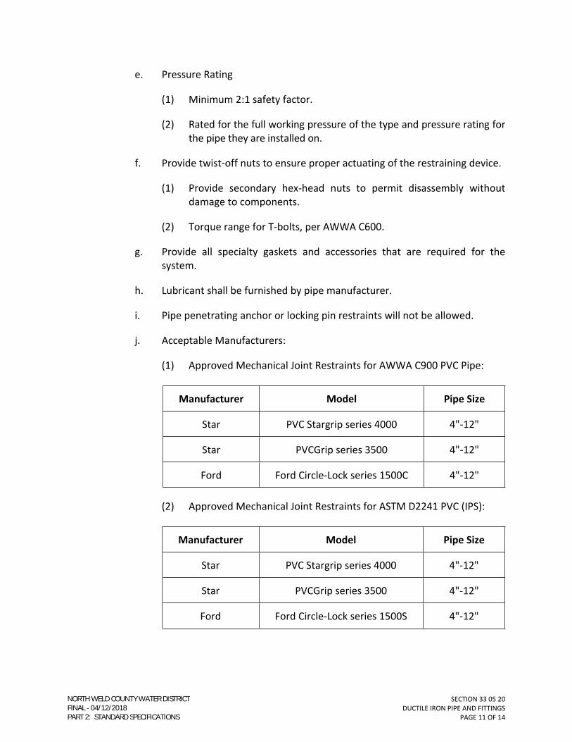
SECTION 33 05 20DUCTILE IRON PIPE AND FITTINGS
PAGE 11 OF 14
e. Pressure Rating
(1) Minimum 2:1 safety factor.
(2) Rated for the full working pressure of the type and pressure rating for the pipe they are installed on.
f. Provide twist-off nuts to ensure proper actuating of the restraining device.
(1) Provide secondary hex-head nuts to permit disassembly without damage to components.
(2) Torque range for T-bolts, per AWWA C600.
g. Provide all specialty gaskets and accessories that are required for the system.
h. Lubricant shall be furnished by pipe manufacturer.
i. Pipe penetrating anchor or locking pin restraints will not be allowed.
j. Acceptable Manufacturers:
(1) Approved Mechanical Joint Restraints for AWWA C900 PVC Pipe:
Manufacturer Model Pipe Size
Star PVC Stargrip series 4000 4"-12"
Star PVCGrip series 3500 4"-12"
Ford Ford Circle-Lock series 1500C 4"-12"
(2) Approved Mechanical Joint Restraints for ASTM D2241 PVC (IPS):
Manufacturer Model Pipe Size
Star PVC Stargrip series 4000 4"-12"
Star PVCGrip series 3500 4"-12"
Ford Ford Circle-Lock series 1500S 4"-12"
NORTH WELD COUNTY WATER DISTRICTFINAL 04/12/2018PART 2: STANDARD SPECIFICATIONS

SECTION 33 05 20DUCTILE IRON PIPE AND FITTINGS
PAGE 12 OF 14
(3) Approved Mechanical Joint Restraints for DI Pipe:
Manufacturer Model Pipe Size
EBAA MEGALUG Series 1100 4"-36"
Ford Series 1400 4"-36"
Star Series 3000 4"-36"
(4) No substitutions allowed.
C. Gaskets
1. The standard MJ gasket shall be made of vulcanized styrene rubber in accordance with AWWA C111.
D. Polyethylene Encasement
1. Shall be manufactured in accordance with AWWA C105.
2. Raw material used to manufacturer polyethylene film shall be in accordance with ASTM D1248: Type 1, Class A, Grade E-1.
3. Polyethylene encasement shall consist of three layers of co-extruded linear low density polyethylene (LLDPE), fused into a single layer.
4. The inside surface of the polyethylene encasement to be in contact with the pipe, fitting, or valve exterior shall be infused with a blend of anti- microbial biocide to mitigate microbiologically influenced corrosion and a volatile corrosion inhibitor to control galvanic corrosion.
5. Properties
a. The polyethylene film shall meet the following properties and requirements:
Property Minimum Requirements
Tensile Strength 3,600 psi, per ASTM D882
Elongation 800%, per ASTM D882
Dielectric Strength 800 V/mil thickness, per ASTM D149
Impact Resistance 600 g, per ASTM D1709 Method B
NORTH WELD COUNTY WATER DISTRICTFINAL 04/12/2018PART 2: STANDARD SPECIFICATIONS

SECTION 33 05 20DUCTILE IRON PIPE AND FITTINGS
PAGE 13 OF 14
Property Minimum Requirements
Thickness 8 mils (0.008-inches)
Propagation Tear Resistance 2,550 grams force, per ASTM D1922
6. Color:
a. Potable Water: Clear or White
b. Non-Potable Water: Purple.
7. Products: V-Bio Enhanced Polyethylene Encasement, or approved equal.
E. Tracer Wire
1. Reference Section 33 14 10 – WATER DISTRIBUTION SYSTEM.
PART 3 - EXECUTION
3.01. INSTALLATION
A. Reference Section 33 14 10 – WATER DISTRIBUTION SYSTEM.
END OF SECTION
NORTH WELD COUNTY WATER DISTRICTFINAL 04/12/2018PART 2: STANDARD SPECIFICATIONS

SECTION 33 05 20DUCTILE IRON PIPE AND FITTINGS
PAGE 14 OF 14
(THIS PAGE INTENTIONALLY LEFT BLANK)
NORTH WELD COUNTY WATER DISTRICTFINAL 04/12/2018PART 2: STANDARD SPECIFICATIONS

SECTION 33 05 22
DIRECTIONAL BORING OF PIPE
PAGE 1 OF 6
SECTION 33 05 22
DIRECTIONAL BORING OF PIPE
PART 1 - GENERAL
1.01. FORMER SECTION NUMBER(S): N/A.
1.02. DESCRIPTION
A. This Section includes materials and installation of fused joint PVC pipe by the
directional boring method.
1.03. RELATED WORK SPECIFIED ELSEWHERE
A. Trenching, Backfilling, and Compacting: 31 23 35.
B. Testing Piping System: 33 05 06.
C. Pipe Boring and Jacking: 33 05 08.
D. Plastic Pressure Pipe: 33 05 29.
E. Water Distribution System: 33 14 10.
1.04. SUBMITTALS
A. Submit in accordance with Section 01 33 21.
B. Qualifications Package:
1. The Contractor shall submit references from at least three similar directional
drilling operations as part of the required submittals within the last three years.
The reference projects shall have been for directional drilling installation of HDPE
water lines, 16-inches in diameter or greater, with one project containing a
minimum single pull-in length of at least 1,500 feet.
2. Directional Drilling Operator and Locator
a. Submit references and resumes listing projects of similar scopes and sizes.
3. Directional Drilling Equipment Information and Certification
a. Submit documentation indicating the applicability of equipment
commensurate with the size and scope of the project. Contractor shall
perform an analysis and calculate the required pull-back force and submit
NORTH WELD COUNTY WATER DISTRICTFINAL 04/12/2018PART 2: STANDARD SPECIFICATIONS

SECTION 33 05 22
DIRECTIONAL BORING OF PIPE
PAGE 2 OF 6
these calculations and specifications on the directional drilling equipment
to be used to ensure that the equipment will be adequate to complete the
project.
C. Work Plan:
1. A description of all equipment to be used, down-hole tools, a list of personnel
and their qualifications and experience (including backup personnel in the event
that an individual is unavailable), and a list of subcontractors.
2. Submit drawings showing proposed method of construction including location of
receiving and sending pits.
3. A schedule of HDD work activity identifying daily work hours and working dates
for each installation.
4. Submit proposed pressure testing location for pipe before directional boring.
5. Submit an accurate record of the crossing location in plan view and profile
depth. Record all changes on the contract drawings as work progresses.
6. Calculations signed and sealed by a professional engineer licensed in the state of
Colorado demonstrating a factor of safety of 20 against buckling of the pipe
considering the materials and equipment to be used.
7. A project safety plan (including MSDS of any potentially hazardous substances to
be used).
8. An environmental protection and contingency plan which shall include but shall
not be limited to drilling fluid containment and cleanup procedures, equipment
and plan for compromised utility installations including electrical and power
lines, water, wastewater and any other subsurface utility.
9. Work plan should be comprehensive, realistic and based on actual working
conditions for this particular project. Plan should document the thoughtful
planning required to successfully complete the project.
PART 2 - MATERIALS
2.01. FUSED JOINT PVC PIPE
A. Refer to Section 33 05 29.
NORTH WELD COUNTY WATER DISTRICTFINAL 04/12/2018PART 2: STANDARD SPECIFICATIONS

SECTION 33 05 22
DIRECTIONAL BORING OF PIPE
PAGE 3 OF 6
2.02. DRILLING FLUID
A. Drilling fluid shall be bentonite and water or a combination of bentonite and polymers
and water formulated to move cuttings to the surface and lubricate the pipe during
pullback.
2.03. DRILL PIPE
A. Drill pipe shall be steel with sufficient strength to withstand the maximum rated
pullback and pushing load of the drilling equipment. Drill pipe joints shall be flush and
capable of transmitting maximum rated torque of the drilling equipment.
2.04. DRILLING EQUIPMENT
A. Drilling equipment shall have a maximum sound power level of 85 dBA (as defined in
ANSI S1.4) at 10-feet when operating within 100-feet of a residential unit. Measure
sound power level in accordance with ISO 3740 and 3744.
1. If the local jurisdiction’s requirements are more stringent, comply with the local
jurisdiction’s requirements.
B. Mixing, pumping, and holding/separation tanks shall be capable of delivering mixed
drilling fluid to the cutting head. Drilling fluids circulating equipment shall be designed
to minimize spillage.
2.05. DOWNHOLE TOOLS
A. Cutting heads, backreamers, and hole openers shall be suitable for the soil and rock
conditions anticipated by the Contractor.
B. Grips, pulling heads, and swivels shall be compatible with the pipe material. Design to
transmit without distortion the maximum rated pullback force of the equipment used.
Grips, pulling heads, and swivels shall be specifically engineered for directional drilling
applications.
C. Tracking equipment shall be capable of determining the location of the cutting head at
depth within ±3 inches.
2.06. TRACER WIRE
A. Refer to Section 33 14 10.
NORTH WELD COUNTY WATER DISTRICTFINAL 04/12/2018PART 2: STANDARD SPECIFICATIONS

SECTION 33 05 22
DIRECTIONAL BORING OF PIPE
PAGE 4 OF 6
PART 3 - EXECUTION
3.01. GENERAL
A. In general, installation of fused joint PVC pipe by directional boring shall follow the pipe
manufacturer’s guidelines in addition to the requirements specified herein.
3.02. INSTALLATION
A. The pipe shall follow the line and grade shown in the Drawings and shall exit the
ground within five feet of the design location.
B. Install the pipe in a manner that does not cause upheaval, settlement, cracking,
movement, or distortion of the surface material including, but not limited to retaining
walls, roadways, and channel bottom.
C. Locate the entrance and exit pits to be within the construction limits delineated on the
Drawings.
3.03. TRENCHING AND EARTHWORK
A. Accomplish trenching and earthwork in accordance with Section 31 23 35.
3.04. PIPE JOINING
A. PVC Pipe
1. Refer to Section 33 05 19.
B. Where the staging area permits, join entire length of pipe to be pulled through bore
prior to commencement of pullback operation. If not feasible because of the length of
the bore and the size of the staging area, each pipe section may be fused or welded to
the previous section before the pull back. Support weight of joined pipe suspended on
rollers to minimize pulling forces.
3.05. PRE-BORE AND POST-BORE PRESSURE TESTING
A. Prior to pulling the pipe through the directional bore hole, the pipe shall be tested by
conducting a low-pressure air test at 4-5 psi test for two hours.
B. Perform pressure testing again after final installation of the pipe and before final
acceptance by NWCWD in accordance with Section 33 05 06.
C. At the Contractor's option, pipe need not be pressure tested before pulling the pipe
through the bore hole. In such case, if the pipe does not pass the pressure test after
installation, then remove the entire pipe from the bore hole, repair the pipe, and
perform pressure testing prior to reinstalling the pipe and again after reinstallation.
NORTH WELD COUNTY WATER DISTRICTFINAL 04/12/2018PART 2: STANDARD SPECIFICATIONS

SECTION 33 05 22
DIRECTIONAL BORING OF PIPE
PAGE 5 OF 6
D. NWCWD will witness the pressure tests and shall be informed a minimum of 48 hours
in advance of pressure tests.
3.06. PILOT BORE
A. Construct a pilot bore at the centerline alignment and grade as shown in the Drawings.
Circulate drilling fluids to maintain an open bore at all times. If the path of the pilot
bore is successfully completed, then proceed with the reaming procedure, and pull the
pipe from the receiving location (exit pit) to the sending location (entry pit). If the pilot
bore could not be successfully completed, then do not proceed with the reaming
procedure until NWCWD, the Engineer, and the Contractor have met to discuss
alternative options for the pipeline crossing. The pilot bore and reaming procedure
shall be controlled by a magnetic survey system including accelerometers,
magnetometers, connector wire, and survey probe. The guidance system shall be
capable of measuring depth, location, pitch, and roll of the bore and shall be able to
indicate depth up to 30 feet.
B. If the pilot bore is abandoned, fill the pilot bore with abandonment grout. Submit mix
design to NWCWD.
3.07. DRILLING FLUID CONTAINMENT AND DISPOSAL
A. Contain and dispose of the drilling mud in accordance with local, state, and federal
regulations and permit conditions. Install erosion and sedimentation control measures
including straw bales to prevent drilling mud from inadvertently spilling out of the
entrance/exit pit. Monitor drilling fluids at the surface to avoid excessive downhole
pressures which may buckle the surface or the pipe during installation.
3.08. BACKREAMING BORE AND PIPE INSTALLATION
A. Upon completing the pilot bore, pull the drill pipe back through the bore using an
oversized backreamer larger than the proposed pipe to be pulled back through the
bore hole. Repeat backreaming as necessary to enlarge the bore to provide sufficient
clearance for the pipe. Attach pulling head and swivel and pull pipe through with
closed end. Pull pipe back in one continuous pull to avoid closure of the bore hole.
3.09. INSTALLATION OF TRACER WIRE
A. Install along the entire pipeline, regardless of pipe material or size.
B. Refer to Section 33 14 10 for other requirements.
END OF SECTION
NORTH WELD COUNTY WATER DISTRICTFINAL 04/12/2018PART 2: STANDARD SPECIFICATIONS

SECTION 33 05 22
DIRECTIONAL BORING OF PIPE
PAGE 6 OF 6
(THIS PAGE INTENTIONALLY LEFT BLANK)
NORTH WELD COUNTY WATER DISTRICTFINAL 04/12/2018PART 2: STANDARD SPECIFICATIONS

SECTION 33 05 29
PLASTIC PRESSURE PIPE
PAGE 1 OF 8
SECTION 33 05 29
PLASTIC PRESSURE PIPE
PART 1 - GENERAL
1.01. FORMER SECTION NUMBER(S): 02622; MS-1; MS-9; MS-33.
1.02. DESCRIPTION
A. This Section addresses plastic pressure pipe from 4- to 30-inch nominal diameters with
ductile iron pipe outside diameter and includes the acceptable materials and
construction practices which may be used in the installation of plastic pressure pipe.
1. All pipe shall be furnished complete with all fittings, specials, and other
accessories.
2. All pipes larger than 30-inch nominal diameter shall be Ductile Iron Pipe.
Reference SECTION 33 05 20 – DUCTILE IRON PIPE AND FITTINGS.
B. This Section covers both potable and non-potable water pipe applications.
1.03. QUALITY ASSURANCE
A. American Water Works Association (AWWA) C900.
B. NSF 61 rated for potable water service.
C. Material shall meet ASTM D 1784.
D. Dimensions shall meet AWWA C900.
E. Joints gaskets shall meet ASTM F477.
F. Joints shall meet ASTM D3139 for tightness.
G. In case of conflict or disagreement between codes, standards, laws, ordinances, rules
and regulations, or within any document itself, the more stringent condition, as
determined by NWCWD, shall govern.
1.04. SUBMITTALS
A. Certification
1. Submit manufacturer’s certification that products meet the referenced standards.
NORTH WELD COUNTY WATER DISTRICTFINAL 04/12/2018PART 2: STANDARD SPECIFICATIONS

SECTION 33 05 29
PLASTIC PRESSURE PIPE
PAGE 2 OF 8
2. Submit manufacturer’s certification that products are NSF 61 certified for potable
water service.
B. Reference SECTION 01 33 21 – SHOP DRAWINGS, SAMPLES, AND O&M MANUALS.
1.05. PRODUCT DELIVERY, STORAGE, AND HANDLING
A. Handling
1. Pipe shall not be handled in a manner which will cause damage to the pipe.
2. Pipe or fittings shall not be dropped.
3. Care must be taken to prevent damage to the pipe and fittings by impact, bending,
compression, or abrasion.
4. Damaged pipe or fittings shall not be installed.
B. Storage
1. Lubricant shall not be stored or handled in a manner which will cause
contamination to the lubricant.
2. Rubber gaskets shall be stored in a location which protects them from
deterioration.
3. Pipe shall be stored in accordance with the manufacturer's specifications.
4. Pipe shall be stored on a surface which provides even support for the pipe barrel.
5. Pipe shall not be stored in such a way as to be supported by the bell.
6. Pipe which has a longitudinal deflection greater than 1/8 inch per foot shall not be
used.
7. Pipe which exhibits any signs of ultraviolet deterioration shall not be used.
PART 2 - MATERIALS
2.01. PLASTIC PRESSURE PIPE 4- THROUGH 30-INCH
A. Shall conform to AWWA C900.
1. Outside diameter basis: Cast Iron Pipe.
2. Pipe Classes
NORTH WELD COUNTY WATER DISTRICTFINAL 04/12/2018PART 2: STANDARD SPECIFICATIONS

SECTION 33 05 29
PLASTIC PRESSURE PIPE
PAGE 3 OF 8
a. Mainline
(1) Either DR 14 (305 psi) or DR 18 (235 psi), as determined by NWCWD,
for pipes 4- through 12-inch.
(2) Either DR 18 (235 psi) or DR 21 (200 psi), as determined by NWCWD,
for pipes 16- through 30-inch.
b. Hydrant Laterals: DR 14 (305 psi).
c. Blowoff Laterals: Shall be DIP, refer to SECTION 33 05 20 – DUCTILE IRON
PIPE.
B. Joints
1. Shall be push-on type with an integral bell and elastomeric gasket.
2. Solvent cement (glued) joints are strictly prohibited.
C. Pipe Length and Color
1. Pipes shall be a standard lay length of 20-Feet.
2. Color
a. Potable water application: blue.
b. Non-potable application: purple.
D. Acceptable Manufacturers
1. North American Pipe Corporation;
2. JM Eagle;
3. Diamond Plastics Corporation;
4. IPEX;
5. Vinyltech Corporation;
6. Certainteed Corporation;
7. No substitutions allowed.
2.02. FUSED JOINT PLASTIC PRESSURE PIPE, 4- THROUGH 16-INCH
A. Fused joint PVC will be approved for use on a case-by-case basis by NWCWD.
NORTH WELD COUNTY WATER DISTRICTFINAL 04/12/2018PART 2: STANDARD SPECIFICATIONS

SECTION 33 05 29
PLASTIC PRESSURE PIPE
PAGE 4 OF 8
B. Shall conform to AWWA C900.
1. Outside Diameter Basis: Cast Iron Pipe.
C. Four-inch (4”) through eight-inch (8”) and twelve-inch (12”) diameter:
1. Pipe Class: DR 14 (305 psi), or as determined otherwise by NWCWD.
D. Sixteen-inch (16”) diameter:
1. Pipe Class: DR 18 (235 psi), or as determined otherwise by NWCWD.
E. Joints
1. Shall be extruded with plain ends.
2. The ends shall be square to the pipe and free of any bevel or chamfer. There shall
be no bell or gasket of any kind incorporated into the pipe. Unless otherwise
specified, fusible polyvinylchloride pipe lengths shall be assembled in the field
with butt-fused joints. The fusion technician shall follow the pipe supplier’s
guidelines for this procedure. All fusion joints shall be completed as described in
this specification.
F. Pipe Length and Color
1. Pipes shall be a standard lay length of 40-Feet or 45-Feet.
a. Random lengths are not acceptable.
2. Color
a. Potable water application: powder blue.
b. Non-potable application: purple.
G. Markings
1. Pipe shall be marked containing the following information: Nominal pipe size, PVC,
Dimension Ratio, AWWA standard designation number, extrusion production-
record code, trademark and cell classification.
H. Acceptable Manufacturers
1. Underground Solutions;
2. No substitutions allowed.
NORTH WELD COUNTY WATER DISTRICTFINAL 04/12/2018PART 2: STANDARD SPECIFICATIONS

SECTION 33 05 29
PLASTIC PRESSURE PIPE
PAGE 5 OF 8
2.03. FITTINGS
A. Reference SECTION 33 05 20 – DUCTILE IRON PIPE AND FITTINGS.
2.04. ACCESSORIES
A. Bolts
1. All nuts and bolts shall be high-strength low-alloy COR-TEN, manufactured in
accordance with AWWA C111.
2. Torque ranges for bolts shall comply with AWWA C600.
B. Mechanical Joint Restraint Devices
1. Refer to Section 33 05 20 – DUCTILE IRON PIPE AND FITTINGS.
C. Bell and Spigot Joint Restraints
1. Bell and spigot restraint devices for pipe sizes larger than twelve inch (12”)
diameter will be considered on a case-by-case basis.
2. Bell and Spigot Joint Restraints, four inch (4”) through twelve inch (12”) diameter.
a. All pipe bell-spigot restraint systems shall be manufactured in accordance
with AWWA C111.
b. Bell restraint glands shall be manufactured of ductile iron conforming to
ASTM A536.
c. Split rings shall incorporate a series of machined serrations in the inside
diameter. Bell restraint glands shall provide 360° contact and support with
the pipe wall so no point loading occurs.
d. Pressure rating
(1) Rated for the full working pressure of the PVC pipe they are installed
on.
(2) Minimum safety factor of 2:1.
e. Threaded Rods and Nuts
(1) All nuts, bolts and rods shall be high-strength low-alloy COR-TEN,
manufactured in accordance with AWWA C111.
f. Acceptable Manufacturers
NORTH WELD COUNTY WATER DISTRICTFINAL 04/12/2018PART 2: STANDARD SPECIFICATIONS

SECTION 33 05 29
PLASTIC PRESSURE PIPE
PAGE 6 OF 8
(1) Star Pipe Products, Series 1100;
(2) EBAA Iron, Series 1500;
(3) Ford Meter Box, Series 1390;
(4) Or approved equal.
D. Tracer Wire
1. Reference SECTION 33 14 10 – WATER DISTRIBUTION SYSTEM.
E. Polyethylene Encasement
1. Shall be manufactured in accordance with AWWA C105.
2. Raw material used to manufacturer polyethylene film shall be in accordance with
ASTM D1248.
3. Minimum of eight (8) mil thickness.
4. Color:
a. Potable Water: Clear or White
b. Non-Potable Water: Purple.
PART 3 - EXECUTION
3.01. INSTALLATION - GENERAL
A. Reference SECTION 33 14 10 – WATER DISTRIBUTION SYSTEM.
B. PVC pipe shall not be installed when the air temperature or the soil temperature is 32°F
or less, unless otherwise approved by NWCWD.
3.02. DELIVERY – PROTECTION OF PIPE
A. The manufacturer shall provide polyethylene material or other suitable bulkheads on
the ends of the pipe and on all special openings to keep the interior of the pipe clean.
Bulkheads shall be substantial enough to remain intact during shipping until the pipe is
installed. Tape or adhesive shall not be applied to the spigot end of the pipe from the
stab-line to the end of the pipe.
B. HANDLING AND STORAGE
NORTH WELD COUNTY WATER DISTRICTFINAL 04/12/2018PART 2: STANDARD SPECIFICATIONS

SECTION 33 05 29
PLASTIC PRESSURE PIPE
PAGE 7 OF 8
1. Pipe shall be off-loaded, loaded, installed, handled, stored and stacked per the
pipe supplier’s guidelines. These guidelines include compliance with the minimum
recommended bend radius and maximum safe pull force for the specific pipe
being used.
3.03. FUSED JOINT PVC PIPE
A. GENERAL
1. Fusible PVC pipe shall be fused by qualified fusion technicians holding current
qualification credentials for the pipe size being fused, as documented by the pipe
supplier.
2. Pipe supplier’s procedures shall be followed at all times during fusion operations.
3. Only appropriately sized and outfitted fusion machines that have been approved
by the pipe supplier shall be used for the fusion process. This includes
requirements for safety, maintenance, and operation with modifications made for
PVC.
B. INSTALLATION
1. Installation guidelines from the pipe suppler shall be followed for all installations.
The fusible PVC pipe will be installed in a manner so as not to exceed the
recommended bending radius guidelines at any time. Where fusible PVC pipe is
installed by pulling in tension, the recommended maximum safe pulling force,
established by the pipe supplier, shall not be exceeded.
2. The pipe ends shall be square to the pipe and free from any bevel or chamfer.
3. Shall be assembled in the field with butt-fused joints.
4. Butt-fusion shall be performed by a qualified fusion technician in accordance with
the manufacturers recommended procedure.
a. Each fusion joint shall be recorded and logged by an approved electronic
monitoring device (Data Logger) connected to the fusion machine. Data
Logger shall utilize the current version of the pipe supplier’s recommended
and compatible software.
b. Only appropriately sized and outfitted fusion machines that have been
approved by the pipe supplier shall be used in the fusion process.
END OF SECTION
NORTH WELD COUNTY WATER DISTRICTFINAL 04/12/2018PART 2: STANDARD SPECIFICATIONS

SECTION 33 05 29
PLASTIC PRESSURE PIPE
PAGE 8 OF 8
(THIS PAGE INTENTIONALLY LEFT BLANK)
NORTH WELD COUNTY WATER DISTRICTFINAL 04/12/2018PART 2: STANDARD SPECIFICATIONS

SECTION 33 14 10
WATER DISTRIBUTION SYSTEM
PAGE 1 OF 16
SECTION 33 14 10
WATER DISTRIBUTION SYSTEM
PART 1 - GENERAL
1.01. FORMER SECTION NUMBER(S): 02713; MS-19; MS-21; MS-22.
1.02. DESCRIPTION
A. This Section addresses the acceptable products, materials, and construction practices
which may be used in the installation of water distribution mains.
B. Items also covered by this Section:
1. Tracer Wire and Accessories.
2. Cathodic Protection Systems and Accessories.
3. Repair Clamps.
4. Reduced-Pressure Backflow Prevention Assemblies.
5. Double-Check Backflow Prevention Assemblies.
6. Detectable Warning Tape.
1.03. QUALITY ASSURANCE
A. Perform all Work as specified herein and in accordance with the latest revisions of the
following codes and standards:
1. Federal, state, and local codes, regulations, and ordinances.
2. American National Standard Institute (ANSI).
3. American Water Works Association (AWWA).
4. American Society for Testing and Materials (ASTM).
B. In case of conflict or disagreement between codes, standards, laws, ordinances, rules
and regulations, or within any document itself, the more stringent condition, as
determined by NWCWD, shall govern.
C. Water system installations shall conform to the regulations of the Colorado Department
of Public Health and Environment and the Water Quality Control Commission.
NORTH WELD COUNTY WATER DISTRICTFINAL 04/12/2018PART 2: STANDARD SPECIFICATIONS

SECTION 33 14 10
WATER DISTRIBUTION SYSTEM
PAGE 2 OF 16
D. Construction staking
1. Reference Section 01 45 00 – QUALITY CONTROL.
E. Horizontal alignment shall not deviate by more than six (6) inches.
F. Vertical alignment shall not deviate by more than three (3) inches, as measured from
the pipe invert.
G. The minimum restrained lengths for Valves and Fittings shall be as specified in the
Standard Details. Refer to "Horizontal Bend Restraint" and “Vertical Bend Restraint.”
1.04. SUBMITTALS
A. Submit information as specified in each Section.
B. Reference SECTION 01 33 21 – SHOP DRAWINGS, SAMPLES, AND O&M MANUALS.
C. CERTIFICATION
1. The manufacturer shall furnish a sworn statement that the inspection and all of
the specified tests have been made, and the results thereof comply with the
requirements of the applicable Standards herein specified. A copy of the
Certification including compliance with NSF/ANSI 61 shall be sent to the District.
1.05. PRODUCT DELIVERY, STORAGE, AND HANDLING
A. Reference the following Sections:
1. 03 30 10 - CAST-IN-PLACE CONCRETE (SMALL VOLUME).
2. 03 40 00 – PRECAST CONCRETE.
3. 31 23 25 – TRENCHING, BACKFILLING, AND COMPACTING.
4. 32 01 10 – PAVEMENT REPAIR AND RESURFACING.
5. 33 05 08 – PIPE BORING AND JACKING.
6. 33 05 10 - TAPPING SLEEVE AND VALVES.
7. 33 05 20 – DUCTILE IRON PIPE AND FITTINGS.
8. 33 05 29 - PLASTIC PRESSURE PIPE.
9. 33 14 18 - SERVICE LINES AND APPRTENANCES.
10. 33 14 20 – VALVES.
NORTH WELD COUNTY WATER DISTRICTFINAL 04/12/2018PART 2: STANDARD SPECIFICATIONS

SECTION 33 14 10
WATER DISTRIBUTION SYSTEM
PAGE 3 OF 16
11. 33 14 22 – HYDRANTS.
1.06. JOB CONDITIONS
A. Foreign material (debris, tools, clothing, or other material), including trench water, shall
not be permitted in the pipe.
B. In order to prevent water, debris, and animals from entering the pipe, the open ends of
the pipe shall have a watertight plug installed when pipe laying is not in progress.
C. Effective measures shall be used to prevent uplifting or floating of the pipeline prior to
completion of the backfilling operations. Dewatering methods and procedures shall be
the responsibility of the installation contractor.
D. Pipe shall not be installed under the following conditions:
1. When the trench contains water.
2. When weather conditions are unsuitable.
a. Temperature is less than 10° Fahrenheit. NWCWD approval is required
when the temperature is 32° Fahrenheit, or less.
3. When the trench bottom is unstable.
E. Pipe and appurtenances shall be protected against dropping and damage.
1. Pipe and appurtenances shall not be used if they are damaged.
PART 2 - MATERIALS
2.01. PIPE
A. Pipe material shall remain the same for each size specified and only interchanged where
another material type is specifically indicated on the approved Construction Drawings.
B. Reference Sections:
1. 33 05 20 – DUCTILE IRON PIPE AND FITTINGS.
2. 33 05 29 - PLASTIC PRESSURE PIPE.
2.02. VALVES
A. Reference Section 33 14 20 – VALVES.
NORTH WELD COUNTY WATER DISTRICTFINAL 04/12/2018PART 2: STANDARD SPECIFICATIONS

SECTION 33 14 10
WATER DISTRIBUTION SYSTEM
PAGE 4 OF 16
2.03. HYDRANTS
A. Reference Section 33 14 22 – HYDRANTS.
2.04. TAPPING SLEEVES AND VALVES
A. Reference Section 33 05 10 – TAPPING SLEEVES AND VALVES.
2.05. SERVICE LINES AND APPURTENANCES
A. Reference Section 33 14 18 – SERVICE LINES AND APPURTENANCES.
2.06. PRECAST CONCRETE STRUCTURES
A. Reference Section 03 40 00 – PRECAST CONCRETE.
2.07. FASTENERS
1. Fasteners for use with flanged joints shall conform to AWWA C111 and AWWA
C115, latest editions.
2.08. METAL SURFACE PROTECTIVE COATING
A. Polyethylene Encasement.
1. Reference Section 33 05 20 – DUCTILE IRON PIPE AND FITTINGS.
2. Reference Section 33 05 29 - PLASTIC PRESSURE PIPE.
B. Spray on rubberized coating for bolts
1. Shall be a rubberized spray-on undercoating.
2. Acceptable Manufacturers.
a. NAPA: Mac's Rubberized Undercoating; or
b. Tite-Seal Rubberized Undercoating.
2.09. TRACER WIRE AND ACCESSORIES
A. Tracer Wire
1. The type of tracer wire installed shall depend upon the method of installation, as
follows:
a. Direct-Bury Installations:
NORTH WELD COUNTY WATER DISTRICTFINAL 04/12/2018PART 2: STANDARD SPECIFICATIONS

SECTION 33 14 10
WATER DISTRIBUTION SYSTEM
PAGE 5 OF 16
(1) Single-conductor, 12-gauge, insulated stranded copper wire rated for
600-volt service.
(2) Suitable for underground service and buried directly with the pipe.
(3) THHN, THWN, or Approved Equal.
b. Trenchless Installations:
(1) Tracer wire shall be a 304 stainless steel alloy, 49 strand, annealed
conductor insulated with 45-mil, high molecular weight, high density
polyethylene (HMW-HDPE) and rated for direct bury use at 30 volts.
Conductor shall be ¼-inch with 7x19 strands and a 6,100-pound break
load.
(2) Insulator shall be 0.045-inches.
(3) Products
(a) Performance Wire and Cable, Inc., Stranded SS /45 mil HMW-
HDPE; or
(b) Approved Equal.
2. Insulation color shall be:
a. Blue for Potable water pipes; or
b. Purple for Non-Potable water pipes.
3. Tracer wire will be connected at all piping intersections to form one continuous
system.
a. Connections shall be watertight.
b. Products
(1) DryConn DBSR Aqua by King Innovations; or
(2) Approved Equal.
B. Test Stations
1. Products
a. 2-inch Cathodic Test Stations by Handley Industries, Inc., or
NORTH WELD COUNTY WATER DISTRICTFINAL 04/12/2018PART 2: STANDARD SPECIFICATIONS
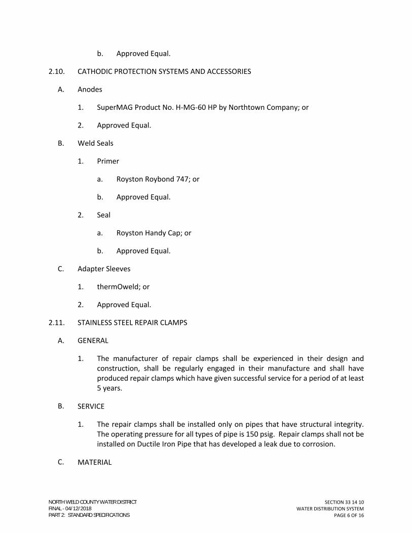
SECTION 33 14 10
WATER DISTRIBUTION SYSTEM
PAGE 6 OF 16
b. Approved Equal.
2.10. CATHODIC PROTECTION SYSTEMS AND ACCESSORIES
A. Anodes
1. SuperMAG Product No. H-MG-60 HP by Northtown Company; or
2. Approved Equal.
B. Weld Seals
1. Primer
a. Royston Roybond 747; or
b. Approved Equal.
2. Seal
a. Royston Handy Cap; or
b. Approved Equal.
C. Adapter Sleeves
1. thermOweld; or
2. Approved Equal.
2.11. STAINLESS STEEL REPAIR CLAMPS
A. GENERAL
1. The manufacturer of repair clamps shall be experienced in their design and
construction, shall be regularly engaged in their manufacture and shall have
produced repair clamps which have given successful service for a period of at least
5 years.
B. SERVICE
1. The repair clamps shall be installed only on pipes that have structural integrity.
The operating pressure for all types of pipe is 150 psig. Repair clamps shall not be
installed on Ductile Iron Pipe that has developed a leak due to corrosion.
C. MATERIAL
NORTH WELD COUNTY WATER DISTRICTFINAL 04/12/2018PART 2: STANDARD SPECIFICATIONS

SECTION 33 14 10
WATER DISTRIBUTION SYSTEM
PAGE 7 OF 16
1. All stainless steel repair clamps and fabrications shall be Type 304 stainless steel
per ANSI 21.11. All welds shall be fully passivated by a chemical technique which
restores the corrosion resistant characteristics of the stainless steel.
D. GASKET
1. Shall be made of virgin styrene butadiene rubber (SBR) or Nitrile (Buna-N, NBR)
compounded for water service. Gasket shall be bonded to stainless steel by
suitable means.
E. BOLTS AND HEX NUTS
1. All bolts shall be of Type 304 stainless steel per ASTM A193 and A194. Stainless
steel hex nuts shall be furnished with a coating to prevent seizing and galling.
2.12. REDUCED-PRESSURE BACKFLOW PREVENTION ASSEMBLY
A. GENERAL
1. All reduced-pressure backflow assemblies shall be manufactured in accordance
with AWWA C511, with the following additional requirements or exceptions.
B. PROTECTION
1. All assemblies shall be protected by a Hot Box fiberglass enclosure and provide
electrical hook-up. All enclosures shall be properly sized and installed according
to the manufacturer.
a. Coordination of the electrical hook-up shall be the responsibility of the
contractor.
C. TESTING
1. The manufacturer shall test all reduced-pressure backflow assemblies according
to AWWA C511.
D. COATING
1. All reduced-pressure backflow assemblies shall be epoxy coated inside and out
according to AWWA C550, for sizes 2-1/2 inches and larger
E. ACCEPTABLE MANUFACTURERS
1. Reduced-Pressure Backflow Assemblies:
a. Manufacturer: Febco
NORTH WELD COUNTY WATER DISTRICTFINAL 04/12/2018PART 2: STANDARD SPECIFICATIONS

SECTION 33 14 10
WATER DISTRIBUTION SYSTEM
PAGE 8 OF 16
(1) Model: 825YA (Brass); or
(2) Model: 880V (Epoxy-Coated);
b. No substitutions allowed.
2. Backflow Enclosures:
a. Manufacturer: Hot Box
(1) Model: HB series.
3. Stainless Steel Repair Clamps:
a. Manufacturer:
(1) Ford - Model: FS1/FS2;
(2) Powerseal - Model 3122AS; or
(3) Romac - Model SS1/SS2.
2.13. DOUBLE CHECK BACKFLOW PREVENTION ASSEMBLY
A. GENERAL
1. All double check backflow assemblies shall be manufactured in accordance with
AWWA C510, with the following additional requirements or exceptions.
B. PROTECTION
1. All assemblies shall be protected by a Hot Box fiberglass enclosure and provide
electrical hook-up. All enclosures shall be properly sized and installed according
to the manufacturer.
C. VALVES
1. Sizes 2-1/2-inch, and larger, shall have Non-Rising Stems (NRS).
D. TESTING
1. The manufacturer shall test all reduced-pressure backflow assemblies according
to AWWA C510.
E. COATING
1. All backflow assemblies shall be epoxy-lined and coated, according to AWWA C550
for sizes 2-1/2-inches and larger.
NORTH WELD COUNTY WATER DISTRICTFINAL 04/12/2018PART 2: STANDARD SPECIFICATIONS
SECTION 33 14 10
WATER DISTRIBUTION SYSTEM
PAGE 9 OF 16
F. ACCEPTABLE MANUFACTURERS
1. Double Check Backflow Assemblies:
a. Manufacturer:
(1) Febco
(a) Model: 850 (Brass); or
(b) Model: 870V (Epoxy-Coated);
(2) No substitutions allowed.
2.14. DETECTABLE WARNING TAPE
A. Thickness
1. 5 mils with no less than .00035 aluminum foil thickness.
B. Width
1. 6-inches.
C. Markings
1. Shall bear the printed identification of the utility line below it, such as “Caution
Buried Water Line Below.”
D. Colors:
1. Blue for potable water; or
2. Purple for non-potable and/or reclaimed water.
E. Products
1. Detectable Underground Marking Tape by Pro-Line Safety Products; or
2. Approved Equal.
PART 3 - EXECUTION
3.01. INSPECTION
A. Pipe barrel and fittings shall be free of dirt or other foreign objects prior to installation.
NORTH WELD COUNTY WATER DISTRICTFINAL 04/12/2018PART 2: STANDARD SPECIFICATIONS
SECTION 33 14 10
WATER DISTRIBUTION SYSTEM
PAGE 10 OF 16
B. Pipe and fittings shall be inspected for cracks, dents, abrasions or other flaws prior to
installation.
C. Pipe and fittings with damaged linings or coatings shall be rejected.
1. Defective pipe shall be marked and remain on the site until removal is approved
by NWCWD.
3.02. PREPARATION
A. Reference Section 31 23 35 – TRENCHING, BACKFILLING, AND COMPACTING.
B. Connections: The locations and elevations of the existing utilities shall be verified prior
to construction.
C. Joints
1. Dirt, oil, grit, and other foreign matter shall be removed from the inside of the bell
and outside of the spigot.
2. A thin film of lubricant shall be applied to the inside of the gasket and the spigot
end of the pipe, per the manufacturer's recommendations.
3. The lubricated joint shall be kept clean until joined.
4. The pipe shall have a depth mark prior to the assembly to ensure that the spigot
end is inserted to the proper depth of the bell end joint.
5. Previously completed joints shall not be disturbed during the jointing operation.
6. After the initial acceptance of the water main, the Contractor shall be responsible
for the repair of any leak, resulting from improper workmanship or materials,
which are discovered within the two (2) year warranty period.
3.03. PIPE INSTALLATION
A. All pipe shall be installed with the bells pointing in the direction that the work is
progressing.
B. The Contractor shall employ effective measures to prevent the separation of joints
during bedding and backfilling operations.
1. Bedding Zone Material shall not be dropped onto unsupported pipe, which has
been set to alignment and grade.
2. Pipe shall be laid and maintained at required lines and grades as specified in the
approved Construction Drawings.
NORTH WELD COUNTY WATER DISTRICTFINAL 04/12/2018PART 2: STANDARD SPECIFICATIONS

SECTION 33 14 10
WATER DISTRIBUTION SYSTEM
PAGE 11 OF 16
C. Ductile iron pipe and fittings shall be installed with a polyethylene encasement.
D. Tracer wire shall be installed with all water mains, regardless of size or material.
1. Route wire to surface at all valve boxes, manholes, and required test stations.
2. Install test stations on pipe runs that are five hundred feet (500’) in length that
have no valve boxes or manholes.
3. Terminate tracer wire in accordance with the applicable Standard Details.
E. The pipe shall be secured in place with the specified Bedding Zone Material consolidated
under and around the pipe.
F. The pipeline shall be installed so that a uniform positive or negative grade is maintained
between the designed high and low points.
G. The minimum depth of cover shall be 5-feet from the finished grade to the top of the
pipe, except as otherwise indicated on the Construction Drawings.
H. The maximum depth of cover shall be 6-feet from the finished grade to the top of the
pipe, except as otherwise indicated on the Construction Drawings.
I. Concrete encasements shall be provided where indicated on the Construction Drawings
only. Written NWCWD approval is required for all other cases.
1. Cast-in-Place Concrete
a. Reference Section 03 30 10 – CAST-IN-PLACE CONCRETE (SMALL VOLUME).
2. Encasements and Sewer Line Crossings
a. Provide concrete encasement where indicated on the Construction
Drawings or required by these Specifications.
b. Where watermains cross sewer lines, and the sewer is above the watermain-
or-less than eighteen inches (18”) clear distance vertically below the
watermain, construct the crossing by one (1) of the following methods:
(1) Sewer shall be placed in a separate twenty foot (20’) long conduit with
ten feet (10’) of separate conduit on either side of water main
centerline.
(2) Encase the sewer pipe with reinforced concrete at least six inches (6”)
thick at all locations within ten feet (10’) either side of the watermain.
Minimum reinforcement shall be one (1) of the following:
NORTH WELD COUNTY WATER DISTRICTFINAL 04/12/2018PART 2: STANDARD SPECIFICATIONS

SECTION 33 14 10
WATER DISTRIBUTION SYSTEM
PAGE 12 OF 16
(a) No. 5 bars, continuous, placed at each corner of the section tied
with No. 3 bars on three-foot (3’-0”) centers.
(b) 6 x 6, W4 x W4 with eight-inch (8”) minimum lap, tied every
twelve inches (12”).
3. Provide suitable backfill or other structural protection to preclude settling or
failure of higher pipe.
J. Connections to Existing pipelines
1. Make each connection at a time authorized by NWCWD which will least interfere
with service.
2. Use suitable fittings for the conditions encountered.
3. Dewater and dispose of water from dewatered lines.
4. Do not contaminate existing potable water lines.
a. Do not permit trench water, mud, or other contaminating substances to
enter pipelines.
5. Swab the interior of new pipe, fittings, and valves installed in existing pipelines
with a solution of five percent (5%) (50,000 ppm) chlorine solution prior to
installation.
6. Only NWCWD shall operate existing valves, hydrants, blowoffs, curb stops, and
other control units.
3.04. THRUST RESTRAINT
A. Concrete anchorage and blocking
1. Concrete anchorage and blocking is required for fire hydrants and allowed by
specific approval only. An approved Construction Drawing does not constitute
approval for use in other location.
2. The minimum size of thrust blocks shall be determined by the Design Engineer for
the specific operating pressures and site conditions.
3. The concrete thrust block bearing surface shall be excavated into undisturbed soil.
a. All loose soil shall be disposed of, and the location where the thrust block is
to be poured shall be carefully shaped to provide a uniform bearing surface
of the required size.
NORTH WELD COUNTY WATER DISTRICTFINAL 04/12/2018PART 2: STANDARD SPECIFICATIONS

SECTION 33 14 10
WATER DISTRIBUTION SYSTEM
PAGE 13 OF 16
b. The concrete thrust block bottom shall be flat, and sides shall be vertical.
c. If soil is to be disturbed, making a concrete thrust block unusable, alternate
restraining systems must be approved by NWCWD prior to pipeline
installation.
4. The concrete thrust block shall be formed to provide access to fittings and
hydrants.
5. Concrete shall be separated from fittings and hydrants by installing 8 mil
polyethylene encasement as a bond breaker.
a. Concrete shall not be poured directly on or over fittings, nuts, bolts, flanges,
etc.
6. NWCWD shall be notified 24 hours before concrete is placed.
B. Mechanical Restraining Devices
1. Reference Section 33 05 20 - DUCTILE IRON PIPE AND FITTINGS.
2. Minimum pipe restrained length shall be per the “Horizontal Bend Restraint ” and
“Vertical Bend Restraint” drawings in the Standard Details.
a. If site conditions (working pressure or soil conditions) vary from the
assumption on the appropriate “Restraint Detail”, the Design Engineer shall
determine the restrained lengths and submit to NWCWD for review.
3. All auxiliary fire hydrant (blowoff) valves shall be restrained to prevent the
movement of the valve during hydrant (blowoff) removal or maintenance.
3.05. INSTALLATION OF PIPELINE APPURTENANCES
A. Valves, hydrants, taps, and other appurtenances to the water distribution lines shall be
installed at the locations shown on the Construction Drawings, or as approved by
NWCWD to accommodate field conditions.
1. Measurements of the actual location of appurtenances shall be made prior to
backfilling for recording in the Project Record Drawings.
2. NWCWD shall inspect/map all pipe, fittings, hydrants, valves, and service lines
prior to backfilling.
B. Dead-end water lines shall have either a fire or flushing hydrant at the end of the
waterline to facilitate the discharge of air and water from the waterline.
NORTH WELD COUNTY WATER DISTRICTFINAL 04/12/2018PART 2: STANDARD SPECIFICATIONS

SECTION 33 14 10
WATER DISTRIBUTION SYSTEM
PAGE 14 OF 16
1. Dead-end water lines that will be extended in the future shall have an inline
isolation valve which controls that section of waterline left in the open position.
a. If the waterline is to be extended in the future, a flushing hydrant may be
installed temporarily, until the extension occurs.
C. Temporary blowoffs which are installed by the Contractor during construction shall be
abandoned at the main prior to acceptance of the waterline.
D. Install fiberglass marker posts at all line valves, air valves, and at intervals not to exceed
1,000 feet as determined by NWCWD.
3.06. PROTECTION OF METAL SURFACES
A. All buried ductile iron pipe shall be installed with polyethylene encasement.
1. Polyethylene Encasement – Method A.
a. Cut polyethylene tube to a length approximately two feet (2’-0”) longer than
that of the pipe section.
b. Slip the tube around the pipe, centering it to provide a one-foot (1’-0”)
overlap on each adjacent pipe section, and bunching it accordion-fashion
lengthwise until it clears the pipe ends.
c. A shallow bell-hole must be made at joints to facilitate installation of the
polyethylene tube.
d. After assembling the pipe joint, make the overlap of the polyethylene tube.
e. Pull the bunched polyethylene from the preceding length of pipe, slip it over
the end of the new length of pipe, and secure in place.
f. Slip the end of the polyethylene from the new pipe section over the end of
the first wrap until it overlaps the joint at the end of the preceding length of
pipe.
g. Secure the overlap in place.
h. Take up the slack width at the top of the pipe to make a snug, but not tight,
fit along the barrel of the pipe, securing the fold at quarter points.
i. Cuts, tears, punctures, and other damage shall be repaired with adhesive
tape or a short length of polyethylene sheet wrapped around the pipe to
cover the damaged area, and secured in place.
NORTH WELD COUNTY WATER DISTRICTFINAL 04/12/2018PART 2: STANDARD SPECIFICATIONS

SECTION 33 14 10
WATER DISTRIBUTION SYSTEM
PAGE 15 OF 16
B. Ductile Iron Fittings
1. All ductile iron fittings shall have a coating applied to the bolts and be
polyethylene-encased.
C. Bell and Spigot Joint Restraints
1. All iron bell harness restraint devices shall have a protective coating applied to
bolts and be polyethylene-encased.
D. If the supplied material has not been factory coated, or the coating has been damaged
by installation, the material shall be protected by one of the following methods:
1. Two coats of coal tar epoxy paint shall be applied to ferrous metal rods, rebar,
clamps, bolts, nuts and other accessories which are subject to submergence or
contact with earth or fill material, and are not encased in concrete.
a. The first coat of coal tar epoxy paint shall be applied to a dry, clean surface.
b. The first coat of coal tar epoxy paint shall be allowed to dry before the
second coat is applied.
2. Ferrous metal rods, rebar, clamps, bolts, nuts and other accessories which are
subject to submergence or contact with earth of fill material, and not encased in
concrete shall be protected with coal tar epoxy paint or a rubberized spray-on
undercoating, and wrapped by a minimum 8 mil polyethylene film.
3.07. DETECTABLE WARNING TAPE
A. Install per the manufacturer’s instructions at the locations shown in the Standard
Details.
END OF SECTION
NORTH WELD COUNTY WATER DISTRICTFINAL 04/12/2018PART 2: STANDARD SPECIFICATIONS

SECTION 33 14 10
WATER DISTRIBUTION SYSTEM
PAGE 16 OF 16
(THIS PAGE INTENTIONALLY LEFT BLANK)
NORTH WELD COUNTY WATER DISTRICTFINAL 04/12/2018PART 2: STANDARD SPECIFICATIONS

SECTION 33 14 18
SERVICE LINES AND APPURTENANCES
PAGE 1 OF 10
SECTION 33 14 18
SERVICE LINES AND APPURTENANCES
PART 1 - GENERAL
1.01. FORMER SECTION NUMBER(S): 02646; MS-14.
1.02. DESCRIPTION
A. This Section addresses the materials and installation of tap saddles, corporation stops,
service lines and curb stops for 1-inch residential services in accordance with AWWA
C800 with the following additional requirements or exceptions.
B. Larger service lines, i.e., 1½-inch and up, will be designed on a case–by–case basis by
NWCWD.
C. 1-inch residential services shall be limited to lengths up to 100-feet.
D. Residential Service runs greater than 100-feet shall be 2-inch.
1.03. QUALITY ASSURANCE
A. Perform all Work as specified herein and in accordance with the latest revisions of the
following codes and standards.
1. Federal, state, and local codes, regulations, and ordinances.
2. American National Standard Institute (ANSI).
3. American Water Works Association (AWWA).
4. American Society for Testing and Materials (ASTM).
B. In case of conflict or disagreement between codes, standards, laws, ordinances, rules
and regulations, or within any document itself, the more stringent condition, as
determined by NWCWD, shall govern.
1.04. SUBMITTALS
A. Certification
1. Submit manufacturer’s certification that products meet the referenced standards.
2. Submit manufacturer’s certification that products are NSF 61 certified for potable
water service.
NORTH WELD COUNTY WATER DISTRICTFINAL 04/12/2018PART 2: STANDARD SPECIFICATIONS
SECTION 33 14 18
SERVICE LINES AND APPURTENANCES
PAGE 2 OF 10
B. Reference SECTION 01 33 21 – SHOP DRAWINGS, SAMPLES, AND O&M MANUALS.
1.05. PRODUCT DELIVERY, STORAGE, AND HANDLING
A. The product shall be handled, stored, and protected in a manner which will prevent
damage to materials, coatings, and finishes.
B. All material shall be kept clean and free from dirt.
PART 2 - MATERIALS
2.01. GENERAL
A. All service lines, valves, and fittings shall be NSF 61 Certified for potable water service.
B. All fittings brass, bronze or iron fittings shall be lead free, per NSF 372.
C. All saddles, valves, and fittings shall conform to AWWA C800.
D. Polyethylene service tubing shall conform to AWWA C901.
2.02. TAPPING SADDLES
A. One-inch (1”) through two-inch (2”), inclusive, tapping saddles shall meet the following
requirements.
1. Shall provide full support around the circumference of the pipe and have bearing
area of sufficient width along the axis of the pipe to prevent distortion of the pipe
when saddle is tightened.
2. All tap saddles shall have female national pipe taper (FNPT) threads in the size
shown on the Drawings.
B. Tap saddles for PVC pipe (IPS)
1. Saddles shall be bronze type body.
2. Acceptable Manufacturers
a. Ford S71;
b. A.Y. McDonald 3892 (2- through 8-inch);
c. A.Y. McDonald 3802 (12-inch);
d. No Substitutions Allowed.
NORTH WELD COUNTY WATER DISTRICTFINAL 04/12/2018PART 2: STANDARD SPECIFICATIONS

SECTION 33 14 18
SERVICE LINES AND APPURTENANCES
PAGE 3 OF 10
C. Tap saddles for PVC pipe, per AWWA C900 (4- through 12-inch)
1. Saddles shall be bronze type body.
2. Acceptable Manufacturers
a. Ford S91;
(1) -404 (4-inch)
(2) -604 (6-inch)
(3) -804 (8-inch)
(4) -1204 (12-inch)
b. A.Y. McDonald 3896;
c. No Substitutions Allowed.
D. Tap saddles for PVC pipe, per AWWA C900 (16- inch and larger)
1. Tap saddle body shall be either:
a. Bronze; or have
b. Epoxy coated iron body.
2. Shall have either a single or a double strap (brass or stainless steel).
3. Acceptable Manufacturers
a. Ford 202BS (4- through 30-inch);
b. Powerseal 3417SW;
c. No Substitutions Allowed.
E. Tap saddles for DIP and Asbestos Cement (AC) pipe
1. Tap saddle body shall be either:
a. nylon; or
b. epoxy coated iron body.
2. Shall have either a single or a double stainless steel strap.
NORTH WELD COUNTY WATER DISTRICTFINAL 04/12/2018PART 2: STANDARD SPECIFICATIONS

SECTION 33 14 18
SERVICE LINES AND APPURTENANCES
PAGE 4 OF 10
3. Acceptable Manufacturers
a. Romac 202N;
b. Ford FC202;
c. A.Y. McDonald 4846A (4- through 12-inch);
d. Powerseal 3417SW (up to 24-inch);
e. No Substitutions Allowed.
2.03. CORPORATION STOPS
A. One-inch (1”) through two-inch (2”), inclusive, corporation stops shall meet the
following requirements.
1. Shall be a ball style valve having a minimum pressure rating of three hundred
pounds per square inch (300 psi).
2. Shall be a male national pipe taper (MNPT) threaded inlet and polyethylene (PE)
tube outlet.
3. Shall have the means to “grip” the polyethylene tubing for mechanical restraint.
4. Acceptable Manufacturers
a. Ford FB1101-4 series;
b. A.Y. McDonald 74704B-33 (1-inch PE);
c. No Substitutions Allowed.
2.04. SERVICE TUBING
A. General
1. Shall be manufactured with 4710 polyethylene resin, per AWWA C901, latest
edition.
2. Shall be SIDR 7 and rated for two hundred fifty pounds per square inch (250 psi)
working pressure.
3. Tubing Color:
a. Potable Water – Blue.
b. Non-Potable Water – Purple.
NORTH WELD COUNTY WATER DISTRICTFINAL 04/12/2018PART 2: STANDARD SPECIFICATIONS
SECTION 33 14 18
SERVICE LINES AND APPURTENANCES
PAGE 5 OF 10
4. Acceptable Manufacturers
a. Endot/Endopure;
b. US Poly/Eagle Pure-core;
c. Centennial Plastics, Inc., CenCore;
d. No Substitutions Allowed.
2.05. CURB STOPS FOR POTABLE WATER SERVICE
A. One-inch (1”) through two-inch (2”), inclusive, curb stops shall meet the following
requirements.
1. Shall be a ball style valve having a minimum pressure rating of three hundred
pounds per square inch (300 psi).
2. Shall be a polyethylene (PE) tube inlet and outlet.
3. Shall have the means to “grip” the polyethylene tubing for mechanical restraint.
4. Acceptable Manufacturers
a. Ford B66 series;
(1) -444 (1-inch PEP)
(2) -777 (2-inch PEP)
b. A.Y. McDonald 76100-33 (1- or 2-inch PEP);
c. No Substitutions Allowed.
2.06. CURB STOPS FOR NON-POTABLE WATER SERVICE
A. One-inch (1”) through two-inch (2”), inclusive, curb stops shall meet the following
requirements.
1. Shall be a ball style valve having a minimum pressure rating of three hundred
pounds per square inch (300 psi).
2. Shall be a polyethylene (PE) tube inlet and outlet.
3. Shall have the means to “grip” the polyethylene tubing for mechanical restraint.
4. Shall be a stop and waste style valve.
NORTH WELD COUNTY WATER DISTRICTFINAL 04/12/2018PART 2: STANDARD SPECIFICATIONS

SECTION 33 14 18
SERVICE LINES AND APPURTENANCES
PAGE 6 OF 10
5. Does not need to meet the “lead free” requirement of NSF 372.
6. Acceptable Manufacturers
a. A.Y. McDonald 76001-FNPT (1-inch); or
b. Ford B66 series w/ stop and waste feature (B66-444SW);
c. No Substitutions Allowed.
2.07. CURB STOP BOXES
A. Shall be a two-piece adjustable screw type valve box made of cast iron meeting ASTM
48, Class 35.
B. Lid name designation:
1. Potable water application: “Water”.
2. Non-potable water application: “Irrigation”.
C. Shall be capable of extending from forty-one inches (41”) to sixty-four inches (64”) in
height.
D. Acceptable Manufacturers
1. Castings C.I. 95-E;
2. Tyler 6500 (95E);
3. AY McDonald 5700;
4. No Substitutions Allowed.
2.08. ACCESSORIES
A. Curb Stop Extension Rods
1. Use on all curb stops.
2. Acceptable Manufacturers
a. A.Y. McDonald 5660 (42-inch length, standard); or
b. Ford (ROD-42, 42-inch);
c. No Substitutions Allowed.
NORTH WELD COUNTY WATER DISTRICTFINAL 04/12/2018PART 2: STANDARD SPECIFICATIONS

SECTION 33 14 18
SERVICE LINES AND APPURTENANCES
PAGE 7 OF 10
B. Polyethylene service tube insert stiffeners
1. Shall be made of 300 series stainless steel.
2. Shall be appropriate size to fit the SIDR 7 (ID-controlled) tubing.
3. Acceptable Manufacturers
a. A.Y. McDonald 6136 (1- through 2-inch PEP);
b. Ford Series 70 for PEP
(1) Insert -72 for 1-inch PEP
c. Or Equal.
PART 3 - EXECUTION
3.01. GENERAL
A. All taps made shall be 1-inch unless specified otherwise.
B. The Contractor shall make all taps and install the service line to the permanent facilities
prior to disinfection and pressure testing of the water main.
C. The Contractor shall not make any taps without prior permission from NWCWD.
D. Reference the applicable Standard Details and as modified on the approved
Construction Drawings.
E. All taps shall be made with a tapping saddle in accordance with these specifications and
the manufacturer's recommendations, unless otherwise approved by NWCWD.
1. A static pressure test of 150 psi for ten (10) continuous minutes, with no visible
leakage or pressure loss, shall be performed prior to the wet tap on all existing
water mains.
F. Service taps on live mains will be made only under the direct supervision of NWCWD.
The Contractor shall coordinate with the NWCWD Representative.
G. NWCWD reserves the right to make taps in lieu of the Contractor and the right to deny
permission for any main to be tapped.
H. Tapping equipment shall be of good quality, used for the purpose intended and used in
accordance with manufacturer's instructions.
NORTH WELD COUNTY WATER DISTRICTFINAL 04/12/2018PART 2: STANDARD SPECIFICATIONS

SECTION 33 14 18
SERVICE LINES AND APPURTENANCES
PAGE 8 OF 10
1. Reference Section 01 60 10 – MATERIALS, EQUIPMENT, AND WORKMANSHIP.
3.02. SERVICE LINE TAPS
A. Taps shall not be made within two (2) feet of any joint or fitting.
B. Taps shall be separated by at least two (2) feet (measured along the pipe length), even
when taps are made on opposite sides of pipe.
C. Taps which are made on the same side of the pipe and within ten 10 feet of each other
(measured along the pipe length), shall be staggered fifteen degrees.
D. Ductile Iron and PVC Pipe Taps: Corporation Stops shall be installed by means of a
tapping saddle.
3.03. CORPORATION STOPS
A. Install so the valve operator is pointing up.
3.04. SERVICE LINES
A. All service lines between the main and curb stop shall be install per the 1-inch SERVICE
ASSEMBLY Standard Detail.
B. All service lines shall be a minimum of four and one half feet (4.5’), and a maximum of
five feet (5’) below the final grade.
C. Use insert stiffeners when assembling compression fitting on polyethylene service
tubing.
D. No couplings shall be allowed between the corporation stop and curb stop.
E. When backfilling the service trench, Bedding Zone Material shall be used at a minimum
of four (4) inches under and six (6) inches above any given location of the service line.
1. Reference Section 31 23 25 – TRENCHING, BACKFILLING, AND
COMPACTING.
F. Service trenches shall be subject to compaction specifications.
1. Reference Section 31 23 25 – TRENCHING, BACKFILLING, AND
COMPACTING.
3.05. CURB STOP
A. Install curb stop valve supported by a concrete block.
NORTH WELD COUNTY WATER DISTRICTFINAL 04/12/2018PART 2: STANDARD SPECIFICATIONS

SECTION 33 14 18
SERVICE LINES AND APPURTENANCES
PAGE 9 OF 10
B. All curb stops shall be a minimum of four and one half feet (4.5’), and a maximum of five
feet (5’) below the final grade.
C. Use insert stiffeners when assembling compression fitting on polyethylene service
tubing.
D. Install curb stop box centered over the valve operator and plumb. Curb stop Box shall
be adjusted to one inch (1”) above final grade.
E. All curb stop shall have operator extension rod installed and secured to valve operator
with a corrosion resistant cotter pin.
1. Rod must extend operator to a minimum of six inches (6”) and a maximum of
twenty-four inches (24”) from the lid of the curb box.
F. After installation, the curb stop valve end shall be wrapped with polyethylene
encasement and secured with tape to keep dirt out of valve.
G. Install a 4”X4” post marking the curbstop box. The post shall be buried 3 ft in the ground
and have 3 ft exposed above grade. Paint post blue.
3.06. INSPECTION
A. The Contractor shall ensure that the tap saddle, corporation stop, service line, and curb
stop remain exposed until after the inspection/mapping and the approval for backfill is
given by NWCWD.
B. All tap and service inspections shall be scheduled with NWCWD.
1. A minimum of 48 hours notice is required on all tap and service inspections.
END OF SECTION
NORTH WELD COUNTY WATER DISTRICTFINAL 04/12/2018PART 2: STANDARD SPECIFICATIONS

SECTION 33 14 18
SERVICE LINES AND APPURTENANCES
PAGE 10 OF 10
(THIS PAGE INTENTIONALLY LEFT BLANK)
NORTH WELD COUNTY WATER DISTRICTFINAL 04/12/2018PART 2: STANDARD SPECIFICATIONS

SECTION 33 14 20VALVES
PAGE 1 OF 12
SECTION 33 14 20
VALVES
PART 1 - GENERAL
1.01. FORMER SECTION NUMBER(S): 02641; MS-4; MS-5; MS-6; MS-11; MS-17; MS-18.
1.02. DESCRIPTION
A. This Section addresses:
1. Gate Valves;
2. Butterfly Valves;
3. Valve Boxes;
4. Air Valves;
5. Ball Valves;
6. Check Valves;
7. Pressure Regulating and Flow Control Valves; and
8. Associated Appurtenances.
1.03. QUALITY ASSURANCE
A. Perform all Work as specified herein and in accordance with the latest revisions of the following codes and standards.
1. Federal, state, and local codes, regulations, and ordinances.
2. American National Standard Institute (ANSI).
3. American Water Works Association (AWWA).
4. American Society for Testing and Materials (ASTM).
5. American Society of Mechanical Engineers (ASME).
B. In case of conflict or disagreement between codes, standards, laws, ordinances, rules and regulations, or within any document itself, the more stringent condition, as determined by NWCWD, shall govern.
NORTH WELD COUNTY WATER DISTRICTFINAL 04/12/2018PART 2: STANDARD SPECIFICATIONS

SECTION 33 14 20VALVES
PAGE 2 OF 12
1.04. SUBMITTALS
A. Certification
1. Submit manufacturer’s certification that products meet the referenced standards.
2. Submit manufacturer’s certification that products are NSF 61 certified for potable water service.
B. Reference SECTION 01 33 21 – SHOP DRAWINGS, SAMPLES, AND O&M MANUALS.
1.05. PRODUCT DELIVERY, STORAGE, AND HANDLING
A. Precautions shall be taken to prevent damage to materials during delivery and storage.
B. Valves shall be stored off of the ground and away from materials that could contaminate potable water systems.
C. Precautions shall be taken to keep all joints and internal parts clean.
PART 2 - MATERIALS
2.01. GENERAL
A. All valves shall open counter-clockwise (left).
B. All valves shall be suitable for frequent operation as well as service involving long periods of inactivity. Valves shall be capable of operating satisfactorily with flows in either direction, and shall provide zero leakage past the seat.
C. All nuts and bolts shall be stainless steel.
D. All buried valves shall have a two (2) inch square operating nut.
1. All operating nuts shall be painted black.
E. Any valve which will be placed in a vault shall have a valve operator which is specifically approved by NWCWD.
2.02. GATE VALVES (2- THROUGH 2 ½-INCH)
A. Shall be resilient seated gate valve manufactured and tested in accordance with AWWA C509.
B. Shall have an operating pressure of 200 psi.
C. Valve ends shall be threaded.
NORTH WELD COUNTY WATER DISTRICTFINAL 04/12/2018PART 2: STANDARD SPECIFICATIONS

SECTION 33 14 20VALVES
PAGE 3 OF 12
D. Coatings/Linings
1. Fusion-bonded epoxy on both inside and outside surfaces in accordance AWWA C550.
E. Acceptable Manufacturers
1. Mueller;
2. Clow;
3. Kennedy;
4. U.S. Pipe;
5. American Flow Control;
6. American AVK;
7. No substitutions allowed.
2.03. GATE VALVES (3- THROUGH 12-INCH)
A. Shall be resilient seated gate valve manufactured and tested in accordance with AWWA C509 or AWWA C515.
B. Shall have an operating pressure of 200 psi.
C. Valve ends shall be mechanical joint (MJ).
D. Coatings/Linings
1. Fusion-bonded epoxy on both inside and outside surfaces in accordance AWWA C550.
E. Acceptable Manufacturers
1. Mueller;
2. Clow;
3. Kennedy;
4. U.S. Pipe;
5. American Flow Control;
6. American AVK;
NORTH WELD COUNTY WATER DISTRICTFINAL 04/12/2018PART 2: STANDARD SPECIFICATIONS

SECTION 33 14 20VALVES
PAGE 4 OF 12
7. No substitutions allowed.
2.04. BUTTERFLY VALVES
A. Shall be used on 16-inch, and larger, nominal pipe sizes.
1. 14-inch pipe is no longer installed in NWCWD.
B. Shall be manufactured and tested in accordance with AWWA C504.
C. Shall have an operating pressure of 250 psi.
D. Valve ends shall be mechanical joint (MJ).
E. Coatings/Linings
1. Fusion-bonded epoxy on both inside and outside surfaces in accordance AWWA C550.
F. Acceptable Manufacturers
1. Mueller;
2. K-Flo;
3. Val-Matic;
4. M&H Valve Company;
5. Pratt;
6. No substitutions allowed.
2.05. TAPPING VALVES
A. Reference Section 33 05 10 – TAPPING SLEEVES AND VALVES.
2.06. VALVE BOXES
A. General
1. The manufacturer of valve box components shall be experienced in their design and construction, shall be regularly engaged in their manufacture and shall have produced valve boxes which have given successful service for a period of at least 5 years.
B. Materials and Construction
NORTH WELD COUNTY WATER DISTRICTFINAL 04/12/2018PART 2: STANDARD SPECIFICATIONS

SECTION 33 14 20VALVES
PAGE 5 OF 12
1. Materials
a. Ductile iron, ASTM A48, Class 35.
2. Type
a. Two piece adjustable, screw-type, only.
3. Shaft size: Five and one-quarter inch (5 ¼”) I.D.
4. Thickness: Three-sixteenth inch (3/16”)
5. Furnish with suitable cover with stamping of:
a. For potable water application: “Water”.
b. For non-potable water application: “Irrigation”.
6. Locking lids shall be supplied with all valve boxes.
C. Coating: Dip in bituminous varnish.
D. Acceptable Manufacturers
1. Castings, Inc. (Model C.I. 664-S);
2. Tyler / Union (Model 664-S);
3. EJ (formerly East Jordan Iron Works);
4. No substitution allowed.
2.07. AIR VALVES
A. Air valves shall be designed for clean water service in accordance with AWWA C512 with the following additional requirements, exceptions, and modifications.
B. Air Release Valves
1. Air Release Valves (ARV), also called small orifice valves, are designed to automatically release small pockets of accumulated air from a pipeline while system operates under pressure exceeding atmospheric pressure.
2. Material of Construction
a. Body
(1) Cast iron or ductile iron; or
NORTH WELD COUNTY WATER DISTRICTFINAL 04/12/2018PART 2: STANDARD SPECIFICATIONS
SECTION 33 14 20VALVES
PAGE 6 OF 12
(2) Reinforced Nylon.
b. Working parts and seats
(1) Brass, stainless steel, or non-corroding material.
c. Float and Trim
(1) Non-corroding, e.g., stainless steel.
3. Finish Coatings
a. Interior and exterior surface shall have an NSF 61 approved epoxy coating.
4. Provide with appropriately-sized NPT threaded connection.
a. Reference the Air Valve Schedule for sizes.
5. Shall have a minimum working pressure of two hundred pounds per square inch (200 psi).
6. Orifice size: 3/32-inch.
7. Vacuum Check: All ARVs shall be equipped with a vacuum check or Checking Feature.
8. Acceptable Manufacturers
a. APCO, Model 200A ARV only;
b. Crispin, PL ARV only series;
c. A.R.I., Model S-050; or
d. No Substitutions Allowed.
C. Air / Vacuum Valves (AVV)
(NOT USED)
D. Combination Air Valves (CAV)
1. CAV suitable for potable water service may be supplied in accordance with the following requirements.
2. Acceptable Manufacturers
a. A.R.I.
NORTH WELD COUNTY WATER DISTRICTFINAL 04/12/2018PART 2: STANDARD SPECIFICATIONS

SECTION 33 14 20VALVES
PAGE 7 OF 12
(1) Model D-040; or
(2) Model D-040-C.
b. Approved equal.
E. Air Valve Schedule
1. Refer to the Standard Details.
2.08. BALL VALVES
A. All shut-off (isolation) valves for air valves shall be ball valves except where specified or indicated otherwise.
B. All ball valves shall be manufactured in accordance with AWWA C800.
C. Any brass part of the valve in contact with potable water shall be made of “no-lead brass” and contain no more than one fifth of one percent (0.20%) total lead content by weight, per NSF 372.
D. Shall have a full port stainless steel or chrome plated bronze ball with a Teflon seat.
E. Minimum WOG pressure rating of four hundred pounds per square inch (400 psi).
F. Provide with female national pipe thread (FNPT) end connections.
G. Lever Operator.
H. Acceptable manufacturers
1. Watts, lead free model;
2. Or equal.
2.09. CHECK VALVES
A. Check valves will be evaluated on a project-specific basis.
2.10. PRESSURE REGULATING AND FLOW CONTROL VALVES
A. GENERAL
1. The Control Valve is an automatic valve designed to control pressures either upstream or downstream of the valve, or to control the flow rate through the valve. It is hydraulically operated, pilot controlled, diaphragm type globe or angle valve.
B. SERVICE
NORTH WELD COUNTY WATER DISTRICTFINAL 04/12/2018PART 2: STANDARD SPECIFICATIONS

SECTION 33 14 20VALVES
PAGE 8 OF 12
1. Control Valves may be used for pressure sustaining, pressure reducing, flow control or a combination thereof.
C. VALVE DESCRIPTION
1. The pressure regulating valve shall be hydraulically operated, pilot controlled, diaphragm actuated, globe or angle pattern valve.
2. The valve shall be fully stainless steel or bronze-trimmed.
3. An indicator rod shall be furnished as an integral part of the valve to show the valve position.
4. The valve shall be designed to provide an access opening in the valve body for removing the internal parts without removing the main body from the service.
D. MATERIAL
1. Valve body, flanges and covers shall be cast iron conforming to ASTM A126, Class B or ASTM A48, Class 35; ductile iron conforming to ASTM A536, grade 65-45-12; or 300 series stainless steel.
2. Bronze castings or parts for internal trim shall conform to ASTM B62.
E. VALVE ENDS
1. All valves shall be furnished with flanged ends sized and drilled in accordance with ANSI B16.1, Class 125.
2. Flanges shall be machined to a flat surface with a serrated finish in accordance with AWWA C207.
F. PILOT VALVE
1. The pilot valve for controlling operation of the main valve shall be a single seated, diaphragm operated and spring loaded type.
2. The pilot valve shall be attached to the main valve with piping and isolation valves so arranged for easy access in making adjustments and also for its removal from the main valve while the main valve is under pressure.
G. SPEED CONTROL
1. The needle valves shall be all bronze or stainless steel and included with the main valve to control both opening and closing speeds.
H. COATINGS
NORTH WELD COUNTY WATER DISTRICTFINAL 04/12/2018PART 2: STANDARD SPECIFICATIONS

SECTION 33 14 20VALVES
PAGE 9 OF 12
1. All internal and external ferrous surfaces except machined or bearing surfaces shall be fusion bonded epoxy, to a minimum dry film thickness of 12 mils.
2. Epoxy coating shall conform to AWWA 550.
I. TESTING
1. The body of the valve shall be given a hydrostatic test to 150% of the operation pressure specified herein.
2. A seat leakage test shall be made at the operating pressure.
J. ACCEPTABLE MANUFACTURERS
1. Manufacturer: CLA VAL
2. Model: Hytrol100-01
3. Coating: Epoxy (Inside and Out)
PART 3 - EXECUTION
3.01. INSTALLATION
A. Valves and valve boxes shall be examined for cracks, dents, abrasions, and other flaws prior to installation.
1. Defective valves and valve boxes shall be marked and removed from the site.
B. Valves
1. Refer to the Standard Details.
2. Flanged valves shall not be buried.
3. The valve shall be installed in such a manner that the operating nut is perpendicular to the ground surface.
4. Encase buried valves with polyethylene to finished grade.
a. Reference Section 33 05 20 – DUCTILE IRON PIPE AND FITTINGS.
5. The joined valve shall be supported in place on compacted Bedding Zone Material with a concrete block under the valve body.
a. Reference Section 31 23 35 – TRENCHING, BACKFILLING, AND COMPACTING.
NORTH WELD COUNTY WATER DISTRICTFINAL 04/12/2018PART 2: STANDARD SPECIFICATIONS
SECTION 33 14 20VALVES
PAGE 10 OF 12
C. Valve Boxes
1. Valve boxes shall be installed on all buried valves.
2. Valve boxes shall be installed so that no stress is transmitted to the valve.
3. Valve operators which are mounted to one side of the valve shall be located to the North or West of the valve.
4. Valve boxes which are to be set over the valve shall be centered, plumb and directly over the operating nut and valve with the top of the box on grade.
a. The soil around the valve box shall be carefully compacted around the barrel, to minimize misalignment and the settling of the backfill.
b. Other valve box types shall be adjusted as required on the Construction Drawings.
c. Valve boxes installed in farmed fields shall have the top of the valve box lid set 18” – 24” below grade.
5. Wrap valve boxes with polyethylene encasement to finished grade.
a. Reference Sections:
(1) 33 05 20 – DUCTILE IRON PIPE AND FITTINGS.
(2) 33 14 10 – WATER DISTRIBUTION SYSTEM.
6. Tracer wire shall be installed in valve boxes, per the Standard Details. NWCWD retains the right to shift the angle cut to the lower portion of the valve box if final grade elevation is uncertain at the time of installation.
D. Valve Stem Extensions
1. Install extended stems on valves where operating nut is more than five feet (5') below finished grade.
a. Stem Extension shall bring operating nut to within four feet (4’) of finished grade.
3.02. AIR VALVES
A. Air valves shall be installed at high points and as shown on the Construction Drawings.
B. Air valves shall be installed in accordance with the Standard Details, and as modified on the approved Construction Drawings.
NORTH WELD COUNTY WATER DISTRICTFINAL 04/12/2018PART 2: STANDARD SPECIFICATIONS

SECTION 33 14 20VALVES
PAGE 11 OF 12
1. Refer to the “AIR VALVE MH ASSEMBLY” details for on- and off-main installations, as appropriate.
3.03. PRESSURE REGULATING VALVES
A. Pressure regulating valves shall be evaluated on a case-by-case basis.
3.04. OPERATION
A. Valves which have been accepted by NWCWD shall be operated by NWCWD personnel only, unless otherwise authorized by a NWCWD representative.
END OF SECTION
NORTH WELD COUNTY WATER DISTRICTFINAL 04/12/2018PART 2: STANDARD SPECIFICATIONS

SECTION 33 14 20VALVES
PAGE 12 OF 12
(THIS PAGE INTENTIONALLY LEFT BLANK)
NORTH WELD COUNTY WATER DISTRICTFINAL 04/12/2018PART 2: STANDARD SPECIFICATIONS

SECTION 33 14 22
HYDRANTS
PAGE 1 OF 8
SECTION 33 14 22
HYDRANTS
PART 1 - GENERAL
1.01. FORMER SECTION NUMBER(S): 02644; MS-10; MS-15.
1.02. DESCRIPTION
A. This Section addresses dry-barrel fire hydrants and flushing hydrants and includes the
acceptable products, materials, and construction practices which may be used in the
construction and installation of fire hydrants.
1.03. QUALITY ASSURANCE
A. Perform all Work as specified herein and in accordance with the latest revisions of the
following codes and standards.
1. Federal, state, and local codes, regulations, and ordinances.
2. American National Standard Institute (ANSI).
3. American Water Works Association (AWWA).
4. American Society for Testing and Materials (ASTM).
5. American Society of Mechanical Engineers (ASME).
B. In case of conflict or disagreement between codes, standards, laws, ordinances, rules
and regulations, or within any document itself, the more stringent condition, as
determined by NWCWD, shall govern.
1.04. SUBMITTALS
A. Certification
1. Submit manufacturer’s certification that products meet the referenced standards.
2. Submit manufacturer’s certification that products are NSF 61 certified for potable
water service.
B. Reference Section 01 33 21 – SHOP DRAWINGS, SAMPLES, AND O&M MANUALS.
NORTH WELD COUNTY WATER DISTRICTFINAL 04/12/2018PART 2: STANDARD SPECIFICATIONS
SECTION 33 14 22
HYDRANTS
PAGE 2 OF 8
1.05. PRODUCT DELIVERY, STORAGE, AND HANDLING
A. Hydrants shall be handled, stored, and protected in such a manner as to prevent damage
to materials, coatings, and finishes.
B. All fittings and joints shall be kept free from dirt, oil, and grease.
PART 2 - MATERIALS
2.01. FIRE HYDRANTS (DRY BARREL)
A. General
1. All fire hydrants shall be manufactured in accordance with AWWA C502.
2. The auxiliary gate valve on the hydrant lateral shall be a six inch (6”) resilient seat
gate valve with a valve box, meeting the requirements of Section 33 14 20 -
VALVES.
3. Operation Style & Direction
a. Reference the specific Fire Protection Authority for the required hydrant
color and opening direction:
(1) Ault Pierce Fire Protection District.
(2) Eaton Fire Protection District.
(3) Galeton Fire Protection District.
(4) Greeley Fire Department.
(5) Nunn Fire Protection District.
(6) Platte Valley Fire Protection District
(7) Poudre Fire Authority.
(8) Western Hills Fire Protection District.
(9) Windsor Severance Fire Protection District.
b. The design engineer shall be responsible for ensuring the correct opening
direction.
c. The operating nut shall be pentagonal “weathershield” type nut. The
pentagon shall measure 1-1/2 inches from point to flat at the base of the
NORTH WELD COUNTY WATER DISTRICTFINAL 04/12/2018PART 2: STANDARD SPECIFICATIONS
SECTION 33 14 22
HYDRANTS
PAGE 3 OF 8
operating nut and 1-7/16 inches at the top; faces shall be tapered uniformly,
and the height of the operating nut shall not be less than 1 inch. A stop nut
located in the hydrant bonnet on the operating shaft shall prevent over
travel of the main valve when being opened.
B. Materials and Construction
1. Type: Dry-barrel with compression shutoff opening against the pressure.
2. Inlet shall be a six-inch (6”) mechanical joint (MJ).
3. Dimensions
a. Size: Five and one-quarter inch (5-1/4”).
b. Inlet Shoe: Six inch (6”) nominal with mechanical joint.
c. Outlet Nozzle Size: Two (2) two and one-half inch (2-1/2”); one (1) four and
one-half inch (4-1/2”).
d. Bury: As dictated by installation location. Refer to the Construction
Drawings.
4. Coatings
a. All coating shall meet AWWA C550.
b. Exterior Color
(1) For potable water application: Reference local fire protection district
requirements.
(2) For non-potable water applications: Valspar, Purple Pantone 522
TGIC, P/N: PT80085, or equal
C. Main Valves and Nozzles
1. The main valve shall be designed so that removal of the assembly from the barrel
is accomplished without excavation in accordance with AWWA C502. Hydrants
shall be 3-way with one pumper nozzle and two hose nozzles. The pumper nozzle
shall be 4-1/2 inches nominal diameter and the hose nozzles shall be 2-1/2 inches
nominal diameter. All nozzles shall be furnished with security chains with one end
of each securely attached to the upper barrel section of the hydrant.
D. Traffic Features
NORTH WELD COUNTY WATER DISTRICTFINAL 04/12/2018PART 2: STANDARD SPECIFICATIONS
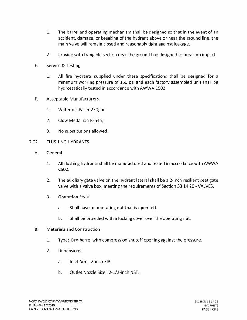
SECTION 33 14 22
HYDRANTS
PAGE 4 OF 8
1. The barrel and operating mechanism shall be designed so that in the event of an
accident, damage, or breaking of the hydrant above or near the ground line, the
main valve will remain closed and reasonably tight against leakage.
2. Provide with frangible section near the ground line designed to break on impact.
E. Service & Testing
1. All fire hydrants supplied under these specifications shall be designed for a
minimum working pressure of 150 psi and each factory assembled unit shall be
hydrostatically tested in accordance with AWWA C502.
F. Acceptable Manufacturers
1. Waterous Pacer 250; or
2. Clow Medallion F2545;
3. No substitutions allowed.
2.02. FLUSHING HYDRANTS
A. General
1. All flushing hydrants shall be manufactured and tested in accordance with AWWA
C502.
2. The auxiliary gate valve on the hydrant lateral shall be a 2-inch resilient seat gate
valve with a valve box, meeting the requirements of Section 33 14 20 - VALVES.
3. Operation Style
a. Shall have an operating nut that is open-left.
b. Shall be provided with a locking cover over the operating nut.
B. Materials and Construction
1. Type: Dry-barrel with compression shutoff opening against the pressure.
2. Dimensions
a. Inlet Size: 2-inch FIP.
b. Outlet Nozzle Size: 2-1/2-inch NST.
NORTH WELD COUNTY WATER DISTRICTFINAL 04/12/2018PART 2: STANDARD SPECIFICATIONS

SECTION 33 14 22
HYDRANTS
PAGE 5 OF 8
c. Depth of Bury: 5-feet, unless shown otherwise on the Construction
Drawings.
3. Operating Pressure: Rated for a minimum of one hundred fifty pounds per square
inch (150 psi).
4. Coatings
a. Coating shall meet AWWA C550.
b. Exterior Color: Red.
5. Provide with section near the ground line designed to break on impact.
C. Acceptable Manufacturer
1. Kupferle Mainguard #77;
2. No substitutions allowed.
2.03. HYDRANT GRAVEL
A. Use Bedding Zone Materials: Crushed Stone or Gravel.
1. Refer to Section 31 23 35.
PART 3 - EXECUTION
3.01. FIRE HYDRANTS
A. All fire hydrants shall be installed in accordance with the "FIRE HYDRANT ASSEMBLY"
drawing in the Standard Details and as modified on the approved Construction
Drawings.
1. All hydrant lateral pipe between the 6-inch gate valve and the hydrant shall be
either:
a. DIP (Special Thickness Class 52) with polyethylene encasement; or
b. PVC (AWWA C900 - DR14).
B. The joining of laterals, valves, and hydrants shall be handled in the same manner as pipe.
1. The fire hydrant shall be installed vertically plumb with the pumper nozzle facing
the direction shown on plans.
NORTH WELD COUNTY WATER DISTRICTFINAL 04/12/2018PART 2: STANDARD SPECIFICATIONS

SECTION 33 14 22
HYDRANTS
PAGE 6 OF 8
2. The fire hydrant shall be set to the elevation staked, to insure that the bury line is
at the final grade.
C. All fire hydrants shall be supported on a minimum of eighteen (18) inches of compacted
hydrant gravel.
1. The fire hydrant shall be supported with a concrete block.
D. A sheet of eight (8) mil polyethylene encasement shall be placed between hydrant shoe
and concrete thrust block, extending up vertically to finish grade, encapsulating the
hydrant barrel.
E. Fire hydrants shall not be placed in concrete sidewalks or pavement.
F. There shall not be a post, fence, vehicle, growth, trash, storage, or other material or
thing, within a three (3) foot radius of the fire hydrant assembly.
1. The ground surrounding the fire hydrant shall slope away from the hydrant at a
minimum grade of 2%, toward the street.
G. After installation of the fire hydrant is complete, the oil/grease reservoir shall be
checked to insure that it is full.
1. If it is necessary to fill the reservoir, it shall be filled with the oil/grease which is
specified by the hydrant manufacturer.
H. If a hydrant is raised, no more than one (1) extension section can be used, unless
approved by NWCWD.
1. Each fire hydrant extension installed shall be inspected, by NWCWD, prior to re-
installation of the fire hydrant body assembly.
3.02. FLUSHING HYDRANTS
A. All flushing hydrants shall be installed in accordance with the Standard Detail entitled,
“2-INCH BLOWOFF ASSEMBLY", and as modified on the approved Construction
Drawings.
B. All flushing hydrant lateral piping shall be lead free brass piping.
C. Install at locations indicated on the Construction Drawings.
3.03. FREEZE PROTECTION
A. Fire hydrants or flushing hydrants installed to standards (where borrow ditch cross
section is involved) will be protected from freezing of the lateral piping by either
NORTH WELD COUNTY WATER DISTRICTFINAL 04/12/2018PART 2: STANDARD SPECIFICATIONS

SECTION 33 14 22
HYDRANTS
PAGE 7 OF 8
maintaining minimum cover of 4.5-feet from invert of the borrow ditch to top of lead
piping or by means of insulating with 4’x8’x2” blueboard insulation on top of lead piping.
3.04. OPERATION
A. Hydrants which have been accepted by NWCWD shall be operated by NWCWD
personnel only, unless otherwise authorized by a NWCWD representative.
END OF SECTION
NORTH WELD COUNTY WATER DISTRICTFINAL 04/12/2018PART 2: STANDARD SPECIFICATIONS

SECTION 33 14 22
HYDRANTS
PAGE 8 OF 8
(THIS PAGE INTENTIONALLY LEFT BLANK)
NORTH WELD COUNTY WATER DISTRICTFINAL 04/12/2018PART 2: STANDARD SPECIFICATIONS

SECTION 33 19 00
METERS AND METER SETS
PAGE 1 OF 8
SECTION 33 19 00
METERS AND METER SETS
PART 1 - GENERAL
1.01. FORMER SECTION NUMBER(S): MS-26; MS-27; MS-28; MS-29; MS-30; MS-31.
1.02. DESCRIPTION
A. This Section addresses the acceptable products, materials, and construction practices
which may be used in the installation of residential, commercial/industrial, and fire
service water meters.
PART 2 - MATERIALS
2.01. RESIDENTIAL METERS (3/4- TRHOUGH 1-INCH)
A. GENERAL
1. All magnetic drive displacement type water meters, 3/4-inch through 1-inch,
furnished under this standard, shall be manufactured in strict accordance with the
latest edition of AWWA C700, C707, and C702 with the following additional
requirements.
B. TYPE
1. All residential meters shall be of the magnetic drive displacement type only.
C. MAIN CASES
1. Main cases shall comply with NSF/ANSI 61 requirements.
2. All meters shall have non-corrosive composite alloy outer case.
3. All meters shall have listed on them the size and direction of water flow through
the meter.
D. REGISTER
1. Electronic.
E. ACCEPTABLE MANUFACTURERS
1. Sensus iPERL;
NORTH WELD COUNTY WATER DISTRICTFINAL 04/12/2018PART 2: STANDARD SPECIFICATIONS

SECTION 33 19 00
METERS AND METER SETS
PAGE 2 OF 8
2. No Substitutions Allowed.
2.02. COMMERCIAL / INDUSTRIAL METERS: (1½ THROUGH 4-INCH)
A. GENERAL
1. All magnetic drive turbine type water meters, 1-1/2 inch through 4 inch, furnished
under this standard, shall be manufactured in strict accordance with the latest
edition of AWWA C701, with the following additional requirements.
B. TYPE
1. All commercial/industrial meters shall be of the class II turbine meters only.
C. CONNECTIONS
1. Flanges on 1-1/2” and 2” size meters shall be oval faced and drilled on the
horizontal axis with a bolt circle diameter of 4-1/2”. Thickness shall be as required
for class 125 round flanges.
2. Flanges for 3” and 4” size meters shall be of the class 125 round type, flat faced,
and shall conform to ANSI 16.1 for specified diameter, drilling and thickness.
D. MEASURING CHAMBER
1. The measuring chamber shall be of unitized construction. The complete chamber
shall consist of the measuring element, calibration device and totalizing register
assembly.
2. The measuring element shall be mounted on a horizontal stationary shaft with
sleeve bearings and be essentially weightless in water.
E. REGISTER
1. The register assembly shall be permanently hermetically sealed. All registers of
similar size and registration shall have contained with them, a standard ratio gear
reduction so as to permit complete interchangeability. The register shall be
assembled to the measuring chamber in such a tamperproof manner requiring
removal only after the measuring chamber is removed from the maincase. The
sweephand reading and odometer wheel detail design shall conform to AWWA
C701.
F. ACCEPTABLE MANUFACTURERS
1. Sensus Omni T2;
2. No Substitutions Allowed.
NORTH WELD COUNTY WATER DISTRICTFINAL 04/12/2018PART 2: STANDARD SPECIFICATIONS

SECTION 33 19 00
METERS AND METER SETS
PAGE 3 OF 8
2.03. FIRE HYDRANT METERS
A. GENERAL
1. All fire hydrant meters shall be manufactured in strict accordance with AWWA
C701.
2. For Fire Meter Vaults, refer to:
a. Section 03 40 00 – PRECAST CONCRETE; and
b. The Standard Details.
B. MATERIAL AND CONSTRUCTION
1. Meter housing shall be aluminum with straightening vanes, strainer, fire hose
couplings and gate valve after meter or after required backflow device.
C. REGISTERS
1. Registers shall be straight read, permanently sealed, magnetic drive and 100 U.S.
Gallon sweep.
D. MEASURING ELEMENT
1. Measuring element shall be easily removed for required maintenance.
E. INSTALLATIONS
1. Fire hydrant meter installation requires a NWCWD approved backflow device.
Meters and backflow device shall be completely supported.
a. Refer to Section 33 14 10 – WATER DISTRIBUTION SYSTEM – for backflow
prevention assemblies.
2. Any fire hydrants and fire hydrant meters that are used and damaged by a
contractor will be repaired by NWCWD at the expense of the contractor.
F. ACCEPTABLE MANUFACTURERS
1. Sensus OMNI H2;
2. No Substitutions Allowed.
2.04. RESIDENTIAL METER SET
A. GENERAL
NORTH WELD COUNTY WATER DISTRICTFINAL 04/12/2018PART 2: STANDARD SPECIFICATIONS

SECTION 33 19 00
METERS AND METER SETS
PAGE 4 OF 8
1. All valves and fittings shall be manufactured in accordance with AWWA C800, with
the following additional requirements or exceptions.
B. METER YOKES
1. Meter yokes shall be male iron pipe thread to male iron pipe thread, include
tandem S bar and shall be of the type listed below or equal, approved by NWCWD
2. Acceptable Manufacturers
a. A.Y. McDonald 16D227QFPP (3/4-inch); or
b. A.Y. McDonald 16-427QFPP (1-inch);
c. No Substitutions Allowed.
C. ANGLE VALVES
1. All angle valves shall be standard port angle valves with a lockwing. All angle
valves shall be of the ball style with a maximum pressure rating of 300 psig of the
type listed below or equal, approved by NWCWD.
a. A.Y. McDonald 764BB (3/4- through 1-inch);
b. No Substitutions Allowed.
D. WYE STRAINERS
1. All wye strainers shall have a maximum pressure rating of 400 psig, stainless steel
screen, cast bronze main valve body per ASTM B584 and tapped with access cover
and pipe plug of the type listed below or equal, approved by NWCWD.
2. Acceptable Manufacturer
a. Wilkins YBP;
b. No Substitutions Allowed.
E. PRESSURE REDUCING VALVE
1. All valves shall have a maximum pressure rating of 300 psig, cast main valve body,
stem, plunger and access covers per ASTM B584, stainless steel fasteners and
strainer screen series 300, natural vulcanized fiber acetal cap gaskets and buna
nitrile elastomers of the type listed below or equal, approved by NWCWD.
2. Acceptable Manufacturer
NORTH WELD COUNTY WATER DISTRICTFINAL 04/12/2018PART 2: STANDARD SPECIFICATIONS

SECTION 33 19 00
METERS AND METER SETS
PAGE 5 OF 8
a. Wilkins
(1) 600XLHRL4 75-125 (3/4-inch)
(2) 600XLL4 25-75 (3/4-inch)
(3) 600XLHLRL4 10-125 (1-inch)
b. No Substitutions Allowed.
F. DUAL ANGLE CHECK VALVE
1. All residential meters shall be equipped with a dual angle check valve to prevent
backflow and back siphonage. Valves must have meter swivel nut inlet and female
iron pipe thread outlet. All dual angle check valves must be of the type listed
below or equal, approved by NWCWD.
2. Acceptable Manufacturer
a. A.Y. McDonald
(1) (NL) 712-3JE43 (3/4-inch);
(2) (NL) 712-3JE54 (1-inch).
b. No Substitutions Allowed.
G. METER PIT RESIDENTIAL
1. All residential meter pits shall have a minimum tensile strength of 2200 psi.
2. Meter pit dimensions shall be 20 inches in diameter by 48 inches in depth and
properly fit meter pit lid assembly.
3. Acceptable Manufacturer
a. DFW Model DFW-242148HW; or
b. Approved Equal.
H. METER PIT LID ASSEMBLY – RESIDENTIAL
1. The manufacturer of meter pit lid assemblies shall be experienced in their design
and construction, shall be regularly engaged in their manufacture and shall have
produced lid assemblies which have given successful service for a period of at least
5 years.
NORTH WELD COUNTY WATER DISTRICTFINAL 04/12/2018PART 2: STANDARD SPECIFICATIONS

SECTION 33 19 00
METERS AND METER SETS
PAGE 6 OF 8
2. Acceptable Manufacturer
a. Castings CI 70B INPL3 Plastic Lid;
b. No Substitutions Allowed.
2.05. 1 ½-INCH METER SET
A. GENERAL
1. All valves and fittings shall be manufactured in accordance with AWWA C151,
C104, C110, C111, C116, C153, C800, with the following additional requirements
or exceptions.
B. PRESSURE REDUCING VALVE
1. All valves shall have a maximum pressure rating of 300 psig of the type listed
below or equal, approved by NWCWD.
2. Acceptable Manufacturer
a. Wilkins 600PHRLU;
b. No Substitutions Allowed.
C. METER PIT – 1 ½-INCH METER
1. All meter pits shall be precast concrete of the type listed below or equal, approved
by NWCWD.
2. Acceptable Manufacturer
a. Old Castle Precast: NWCWD Typical Vault for 1-1/2 to 4-inch Meters;
b. No Substitutions Allowed.
2.06. 2- TO 4-INCH METER SET
A. GENERAL
1. All valves and fittings shall be manufactured in accordance with AWWA C151,
C104, C110, C111, C116, C153, C800, with the following additional requirements
or exceptions.
B. PRESSURE REDUCING VALVE
NORTH WELD COUNTY WATER DISTRICTFINAL 04/12/2018PART 2: STANDARD SPECIFICATIONS

SECTION 33 19 00
METERS AND METER SETS
PAGE 7 OF 8
1. All valves shall have a maximum pressure rating of 300 psig of the type listed
below or equal, approved by NWCWD.
2. Acceptable Manufacturer
a. Wilkins 2" Meter Set (Light Industrial/Commercial) 500YSBRHRP (125-75) or
600 PHRLU; or
b. Watts LFN 55B (Low Range Only with FNPT inlet/outlet); or
c. 2" and Larger meter set Cla-Val PRV sized by engineer
C. METER PIT
1. All meter pits shall be precast concrete, per Section 03 40 00 – PRECAST
CONCRETE.
2. Refer to the Standard Details.
PART 3 - EXECUTION
3.01. GENERAL
A. Install per manufacturer’s recommendations and in accordance with these
Specifications and the Standard Details.
END OF SECTION
NORTH WELD COUNTY WATER DISTRICTFINAL 04/12/2018PART 2: STANDARD SPECIFICATIONS

SECTION 33 19 00
METERS AND METER SETS
PAGE 8 OF 8
(THIS PAGE INTENTIONALLY LEFT BLANK)
NORTH WELD COUNTY WATER DISTRICTFINAL 04/12/2018PART 2: STANDARD SPECIFICATIONS

DESIGN CRITERIA AND STANDARDS
POTABLE WATER DISTRIBUTION SYSTEM
PART 3
STANDARD DETAILS

(THIS PAGE INTENTIONALLY LEFT BLANK)
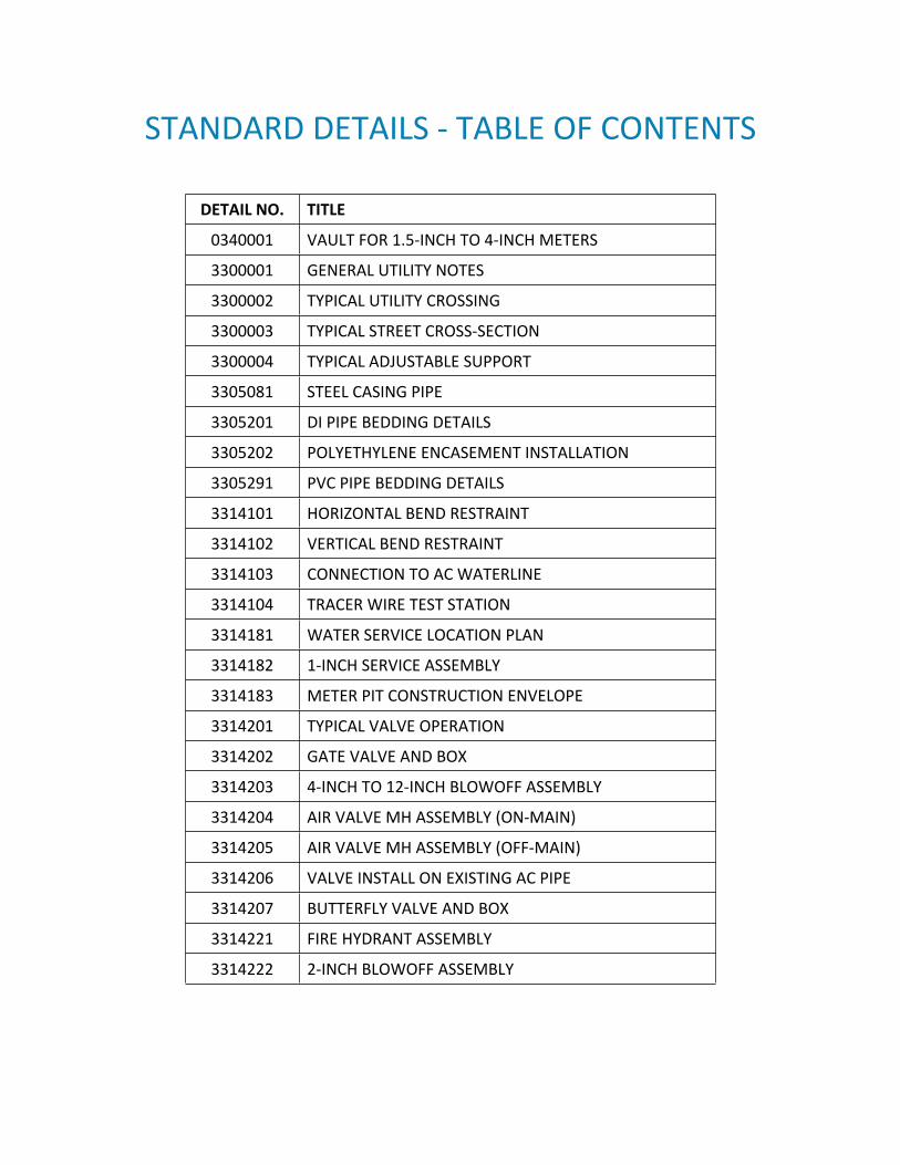
STANDARD DETAILS - TABLE OF CONTENTS
DETAIL NO. TITLE
0340001 VAULT FOR 1.5-INCH TO 4-INCH METERS
3300001 GENERAL UTILITY NOTES
3300002 TYPICAL UTILITY CROSSING
3300003 TYPICAL STREET CROSS-SECTION
3300004 TYPICAL ADJUSTABLE SUPPORT
3305081 STEEL CASING PIPE
3305201 DI PIPE BEDDING DETAILS
3305202 POLYETHYLENE ENCASEMENT INSTALLATION
3305291 PVC PIPE BEDDING DETAILS
3314101 HORIZONTAL BEND RESTRAINT
3314102 VERTICAL BEND RESTRAINT
3314103 CONNECTION TO AC WATERLINE
3314104 TRACER WIRE TEST STATION
3314181 WATER SERVICE LOCATION PLAN
3314182 1-INCH SERVICE ASSEMBLY
3314183 METER PIT CONSTRUCTION ENVELOPE
3314201 TYPICAL VALVE OPERATION
3314202 GATE VALVE AND BOX
3314203 4-INCH TO 12-INCH BLOWOFF ASSEMBLY
3314204 AIR VALVE MH ASSEMBLY (ON-MAIN)
3314205 AIR VALVE MH ASSEMBLY (OFF-MAIN)
3314206 VALVE INSTALL ON EXISTING AC PIPE
3314207 BUTTERFLY VALVE AND BOX
3314221 FIRE HYDRANT ASSEMBLY
3314222 2-INCH BLOWOFF ASSEMBLY

(THIS PAGE INTENTIONALLY LEFT BLANK)

3'-6"
2'-6"
8'-0"
4'-0"
3'-0"
5'-0"
NO
M D
EP
TH
;
CO
NT
RA
CT
OR
TO
V
ER
IF
Y
MANHOLE STEP @ 12" O.C.
KNOCKOUT W/ GROUT (NO
LINK-SEALS)
MANHOLE RING AND COVER,
PER SECTION 03 40 00
VALVE BOX ASSEMBLY, PER
SECTION 33 14 20
GATE VALVE, PER SECTION 33
14 20; SIZE SAME AS LINE PIPE
DI MJ SOLID SLEEVE (SHORT) ,
PER SECTION 33 05 20
DI MJ TAPPED TEE W/ 2" FNPT
OUTLET, PER SECTION
33 05 20
1
2
3
4
5
6
KEY NOTES:
1. REFER TO SECTION 03 40 00 FOR PRECAST VAULT
REQUIREMENTS. 6-INCH AND LARGER METER VAULTS, SIMILAR.
2. RUN DIP THROUGH VAULT AS SHOWN - WITH NO JOINTS PRIOR TO
FIRST MJ FITTING ON EACH SIDE OF VAULT.
3. NWCWD WILL INSTALL HARDWARE INSIDE VAULT ONCE
COMPLETE. COORDINATE WITH NWCWD.
4. BOTTOM SECTION OF WALLS SHALL BE INTEGRAL W/ BASE SLAB -
NO JOINTS AT WALL-TO-SLAB INTERFACE.
5. CONTINUE 2" PIPING TO FLUSHING HYDRANT PER STD DETAIL NO.
3314222 (ON-MAIN). NIPPLE LENGTH TBD IN FIELD. CONTACT
NWCWD TO PADLOCK FLUSHING HYDRANT AFTER INSTALLATION.
6. ALL DI FITTINGS AND VALVES SHALL BE FUSION-BONDED EPOXY
COATED.
7. BACKFILL AND COMPACT PIPING, FITTINGS, AND VALVES ON EACH
SIDE OF VAULT, PER SECTION 31 23 35.
NOTES:
30"Ø BLOCK OUT FOR
MANHOLE COVER
PRECAST CONCRETE VAULT
(8'-0" L X 6'-0" W X 7'-0" H), SEE NOTES
BASE
SLAB
12"Ø x 4" DEEP
SUMP
PRECAST CONCRETE
VAULT ROOF
COMPACTED NATIVE
BACKFILL, TYP
±9'-0"
±7'-0"
9"
9"
1'-6"
TYP
2'-0"
TYP
±8'-0"
6'-0"
TYP
TYP
TYP
SCALE:
SECTION
1/4"=1'-0"
A
-
SCALE:
ROOF PLAN
1/4"=1'-0"
A
-
1
7
5
SCALE:
PLAN
1/4"=1'-0"
3
2
4
6
2" OUTLET, NOTE 5
DIP, NOTE 2
7
FLOW
6"
TYP
BASE SLAB,
NOTE 4
MIN. 12" THK LAYER
OF 1
1
2
" CRUSHED
STONE, PER SECTION
31 23 35
NOTE 5
NOTE 7,
TYP
DETAIL NO:NORTH WELD COUNTYWATER DISTRICT
970-356-3020www.nwcwd.org
0340001
NORTH WELD
C
O
U
N
T
Y
W
A
TER
D
I
S
T
R
I
C
T
ESTABLISHED
1962
NWCWD APPD:
ORIG DATE:
REV DATE: 04/12/2018
05/01/2017
GMVAULT FOR 1.5-INCH
TO 4-INCH METERS

(THIS PAGE INTENTIONALLY LEFT BLANK)

1. ALL WATER LINE CONSTRUCTION SHALL CONFORM TO NORTH WELD COUNTY WATER DISTRICT'S
(NWCWD) DESIGN CRITERIA AND STANDARDS CURRENT AT DATE PERTAINING TO THIS DEVELOPMENT.
PROVIDE SUBMITTALS OF ALL MATERIALS TO NWCWD FOURTEEN (14) DAYS PRIOR TO CONSTRUCTION
FOR FULL APPROVAL.
2. PRIOR TO THE COMMENCEMENT OF ANY CONSTRUCTION, THE CONTRACTOR SHALL CONTACT ALL
UTILITY COMPANIES AND DEPARTMENTS TO COORDINATE SCHEDULES.
3. ALL CONSTRUCTION ACTIVITIES MUST COMPLY WITH THE COLORADO DEPARTMENT OF PUBLIC HEALTH
AND ENVIRONMENT'S (CDPHE) PERMITTING PROCESS FOR "STORM WATER DISCHARGES ASSOCIATED
WITH CONSTRUCTION ACTIVITY." FOR INFORMATION, CONTACT: CDPHE, WATER QUALITY CONTROL
DIVISION, SQCD-PE-B2, 4300 SOUTH CHERRY CREEK DRIVE SOUTH, DENVER, COLORADO 80222-1530,
ATTENTION: PERMITS AND ENFORCEMENT SECTION.
4. IF DEWATERING IS USED TO INSTALL UTILITIES, CULVERTS, ETC., A CDPHE CONSTRUCTION
DEWATERING DISCHARGE PERMIT IS REQUIRED FOR DISCHARGING INTO A STORM SEWER, CHANNEL,
IRRIGATION DITCH, OR ANY WATERS OF THE UNITED STATES.
5. THE CONTRACTOR SHALL OBTAIN SEPARATE ACCESS OR UTILITY PERMITS FROM CDOT, COUNTY
AGENCY OR APPROPRIATE MUNICIPALITY BEFORE UNDERTAKING ANY CONSTRUCTION WORK IN
EXISTING HIGHWAY, ROAD, OR STREET RIGHTS-OF-WAY.
6. COORDINATE WITH NWCWD BEFORE BACKFILLING OF ANY WATERLINE FOR SURVEY AND INSPECTION.
NWCWD REQUIRES EVERY JOINT, FITTING, TAP, AND APPURTENANCE TO BE SURVEYED.
7. ALL WATERLINES SHALL MAINTAIN A MINIMUM COVER OF FIVE FEET (5'-0") AND A MAXIMUM COVER OF
SIX FEET (6'-0"), UNLESS OTHERWISE SPECIFIED.
8. ALL WATERLINES SHALL MAINTAIN GRADE AS SHOWN ON PLANS.
9. TRACER WIRE IS TO BE INSTALLED ON TOP OF ALL PIPING. REFER TO SECTION 33 14 10 FOR
REQUIREMENTS.
10. ALL UNDERGROUND DUCTILE IRON FITTINGS AND PIPE SHALL BE TIGHTLY WRAPPED IN POLYETHYLENE
ENCASEMENT, PER SECTION 33 05 20.
11. ALL VALVES, FITTINGS, AND HYDRANTS ARE TO BE MECHANICALLY RESTRAINED TO THE PIPE USING
APPROVED MECHANICAL RESTRAINT DEVICES, PER SECTION 33 05 20.
12. VALVE OPENING DIRECTION, PER DETAIL NO. 3314201, "TYPICAL VALVE OPERATION".
13. ALL WATER TAPS ARE INDIVIDUAL TAPS EXCLUSIVE OF ANY AND ALL OTHER UNITS. REFER TO DETAIL
NO. 3314181, "WATER SERVICE LOCATION PLAN".
14. WATER SERVICE LINES SHALL BE 1" IPS POLYETHYLENE TUBING AND HAVE A 1" CURBSTOP INSTALLED.
WATER SERVICE LINES SHALL EXTEND THROUGH THE FRONT LOT AND SHALL BE MARKED WITH A 4"X4"
WOODEN POST, EXPOSED THREE (3) FEET ABOVE FINISHED GRADE. REFER TO DETAIL NO. 3314182,
"1-INCH SERVICE ASSEMBLY".
GENERAL UTILITY NOTES:
DETAIL NO:NORTH WELD COUNTYWATER DISTRICT
970-356-3020www.nwcwd.org
3300001
NO
RTH WELD
C
O
U
N
T
Y
W
A
T
ER
D
I
S
T
R
I
C
T
ESTABLISHED
1962
NWCWD APPD:
ORIG DATE:
REV DATE: 04/12/2018
05/01/2017
GM
GENERAL UTILITY NOTES

(THIS PAGE INTENTIONALLY LEFT BLANK)

5'-0"
5'-0"
5'-0" - 6'-0"
MJ 45° BEND
DI OR
PVC PIPE
MJ 45° BEND
MJ 45° BEND
MJ 45°
BEND
CONDUIT OR
CONFLICTING UTILITY
5' FROM EA EDGE OF UTILITY
CO
VE
R V
AR
IE
S
(N
OT
E 4)
OFFICIAL STREET GRADE
1. REFER TO NWCWD'S STANDARD
SPECIFICATIONS FOR ACCEPTABLE PARTS AND
MATERIALS.
2. CLEARANCE MAY BE GREATER, DEPENDING ON
CROSSED UTILITY OWNER'S SPECIFIC
REQUIREMENTS.
3. RESTRAIN ALL JOINTS.
4. POTHOLE CROSSED UTILITIES TO DETERMINE
EXACT ELEVATION AT CROSSING LOCATION
PRIOR TO INSTALLATION OF WATERLINE.
NOTES:
P
I
P
E
O
D
18" MIN
(NOTE 2)
DETAIL NO:NORTH WELD COUNTYWATER DISTRICT
970-356-3020www.nwcwd.org
3300002
NORTH WELD
C
O
U
N
T
Y
W
A
TER
D
I
S
T
R
I
C
T
ESTABLISHED
1962
NWCWD APPD:
ORIG DATE:
REV DATE: 04/12/2018
05/01/2017
GM
TYPICAL UTILITY CROSSING

(THIS PAGE INTENTIONALLY LEFT BLANK)

2'-6" 4'-6" 28'-0"
OFFICIAL
STREET GRADE
2'-6"4'-6"
C
L
5'-0"
MIN
GAS
POWER
PHONE
SANITARY SEWER
WATER
FL
PL
NOTES:
1. REFER TO NWCWD'S STANDARD SPECIFICATIONS FOR ACCEPTABLE
PARTS AND MATERIALS.
2. THE MINIMUM 10-FOOT SEPARATION IS MEASURED FROM THE
OUTSIDES OF EACH PIPE/UTILITY, I.E., NOT FROM THE CENTERLINES.
PL
10' MIN.
(NOTE 2)
DETAIL NO:NORTH WELD COUNTYWATER DISTRICT
970-356-3020www.nwcwd.org
3300003
NORTH WELD
C
O
U
N
T
Y
W
A
TE
R
D
I
S
T
R
I
C
T
ESTABLISHED
1962
NWCWD APPD:
ORIG DATE:
REV DATE: 04/12/2018
05/01/2017
GM
TYPICAL STREET CROSS-SECTION

(THIS PAGE INTENTIONALLY LEFT BLANK)

1. HD - HEAVY DUTY; LD - LIGHT DUTY; SST - STAINLESS STEEL.
2. SIMILAR PREFABRICATED SUPPORT BY GRINNELL, BEELINE, OR
EQUAL MAY BE SUBSTITUTED.
VA
RIE
S (48" M
AX
A
T F
ULL E
XT
EN
T)
6" M
IN
(W
HE
N F
ULLY
-E
XT
EN
DE
D)
RADIUS TO MATCH
PIPE OR VALVE BODY
1/2" x 8" x 8" SST PLATE (LD)
3/4" x 10" x 10" SST PLATE (HD)
1/2" SST ANCHOR BOLTS, DRILL
AND EPOXY 4" MIN EMBED
3/4" x 4" x 6" BAR (HD)
5/8" x 3" x 6" BAR (LD)
1" Ø SST THREADED ROD (LD)
2" Ø SST THREADED ROD (HD)
1" SST HEAVY DUTY HEX NUT (LD)
2" SST HEAVY DUTY HEX NUT (HD)
1/2" x 3" x 3" SST BAR (LD)
3/4" x 5" x 5" SST BAR (HD)
2" DIA. SST PIPE (LD)
3" DIA. SST PIPE (HD)
1/4" NEOPRENE PAD
(ASTM D2000; 1BC 610)
NOTES:
DETAIL NO:NORTH WELD COUNTYWATER DISTRICT
970-356-3020www.nwcwd.org
3300004
NORTH WELD
C
O
U
N
T
Y
W
A
TER
D
I
S
T
R
I
C
T
ESTABLISHED
1962
NWCWD APPD:
ORIG DATE:
REV DATE: 04/12/2018
05/01/2017
GM
TYPICAL ADJUSTABLE SUPPORT

(THIS PAGE INTENTIONALLY LEFT BLANK)

CARRIER PIPE
SIZE (IN)
4"
1
2
"
2
6"
1
2
"
2
8"
3
4
"
2
12"
3
4
"
2
RESTRAIN PIPE TO CASING ON
BOTH ENDS. SEE RESTRAINT
DETAIL THIS SHEET
RESTRAINED JOINT
CARRIER PIPE
CASING PIPE, PER
SECTION 33 05 08
CASING SPACER, TYP
SEAL ENDS WITH HIGH
DENSITY RUBBER
SEALS AND STAINLESS
STEEL BANDS
CENTERLINE SECTION
END SECTION
CARRIER PIPE
CASING
CASING SPACER
CARRIER PIPE
2"
MIN
STEEL CASING
ROD SCHEDULE
ALL BOLTS AND RODS TO BE COATED
AND POLYETHYLENE-ENCASED.
NOTE:
RESTRAINT DETAIL
ROD SIZE ASSUMES 200 PSI TEST PRESSURE AND A307 STEEL.
NOTE:
A307 BOLT W/ NUTS AND
WASHERS (TYP)
CASING END SEAL
MECHANICAL RESTRAINT
GLAND
BOLTS TO BE SPACED
EQUALLY AROUND
PERIMETER OF PIPE
SEE ROD SCHEDULE FOR
DIAMETER AND QUANTITY
6" x 6" x
3
4
" ANGLE
CUT 4" LONG
ANODE, CAD-WELDED
TO CASING PIPE, PER
SECTION 33 14 10.
DIAMETER
OF ROD (IN)
QUANTITY OF
RODS
16"
5
8
"
6
CARRIER
PIPE
DETAIL NO:NORTH WELD COUNTYWATER DISTRICT
970-356-3020www.nwcwd.org
3305081
NORTH WELD
C
O
U
N
T
Y
W
A
TER
D
I
S
T
R
I
C
T
ESTABLISHED
1962
NWCWD APPD:
ORIG DATE:
REV DATE: 04/12/2018
05/01/2017
GM
STEEL CASING PIPE

(THIS PAGE INTENTIONALLY LEFT BLANK)

12" MIN
TRENCH RESTORATION
12" MIN
TRENCH DETAIL
BEDDING DETAIL
NOTES:
1. TRENCH BACKFILL MATERIAL SHALL BE IN ACCORDANCE WITH SECTION 31 23 35.
2. "BEDDING ZONE MATERIALS," AS APPROVED BY ENGINEER. REFER TO SECTION 31 23 35.
3. OVER-EXCAVATE UNSUITABLE MATERIAL, & REPLACE WITH "STABILIZATION MATERIAL" AS
REQUIRED ON THE DRAWINGS - OR - AS DIRECTED BY THE ENGINEER. REFER TO SECTION 31 23
35.
4. REFER TO NWCWD'S STANDARD SPECIFICATIONS FOR ACCEPTABLE PARTS AND MATERIALS.
ACTUAL SIDE SLOPE
BY CONTRACTOR
TRENCH BACKFILL
MATERIAL, SEE NOTE 1
SEE BEDDING
DETAIL BELOW
POLYETHYLENE-
ENCASED DIP
TRENCH
NEAT LINE
TRACER WIRE, PER
SECTION 33 14 10,
ATTACHED TO PIPE
POLYETHYLENE-
ENCASED DIP
2'-6"
MIN WIDTH OF TRENCH
= PIPE O.D. + 16"
PIP
E B
AS
E,
PE
R S
PE
C
BEDDING ZONE
MATERIAL, SEE NOTE 2
STABILIZATION
MATERIAL, SEE NOTE 3
PE
R
SP
EC
O
.
D
.
SEE NOTE 1
6"
MIN
BE
DD
IN
G Z
ON
E
OVER-EXCAVATION
AND STABILIZATION
MATERIAL, PER NOTE 3
DETECTABLE WARNING
TAPE, PER SECTION 33 14 10
O.D. + 16"
O.D.
DETAIL NO:NORTH WELD COUNTYWATER DISTRICT
970-356-3020www.nwcwd.org
3305201
NORTH WELD
C
O
U
N
T
Y
W
A
TER
D
I
S
T
R
I
C
T
ESTABLISHED
1962
NWCWD APPD:
ORIG DATE:
REV DATE: 04/12/2018
05/01/2017
GM
DI PIPE BEDDING DETAILS

(THIS PAGE INTENTIONALLY LEFT BLANK)
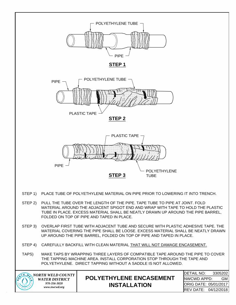
STEP 1) PLACE TUBE OF POLYETHYLENE MATERIAL ON PIPE PRIOR TO LOWERING IT INTO TRENCH.
STEP 2) PULL THE TUBE OVER THE LENGTH OF THE PIPE. TAPE TUBE TO PIPE AT JOINT. FOLD
MATERIAL AROUND THE ADJACENT SPIGOT END AND WRAP WITH TAPE TO HOLD THE PLASTIC
TUBE IN PLACE. EXCESS MATERIAL SHALL BE NEATLY DRAWN UP AROUND THE PIPE BARREL,
FOLDED ON TOP OF PIPE AND TAPED IN PLACE.
STEP 3) OVERLAP FIRST TUBE WITH ADJACENT TUBE AND SECURE WITH PLASTIC ADHESIVE TAPE. THE
MATERIAL COVERING THE PIPE SHALL BE LOOSE. EXCESS MATERIAL SHALL BE NEATLY DRAWN
UP AROUND THE PIPE BARREL, FOLDED ON TOP OF PIPE AND TAPED IN PLACE.
STEP 4) CAREFULLY BACKFILL WITH CLEAN MATERIAL THAT WILL NOT DAMAGE ENCASEMENT.
TAPS) MAKE TAPS BY WRAPPING THREE LAYERS OF COMPATIBLE TAPE AROUND THE PIPE TO COVER
THE TAPPING MACHINE AREA. INSTALL CORPORATION STOP THROUGH THE TAPE AND
POLYETHYLENE. DIRECT TAPPING WITHOUT A SADDLE IS NOT ALLOWED.
POLYETHYLENE TUBE
PIPE
STEP 1
POLYETHYLENE TUBE
PIPE
STEP 2
PLASTIC TAPE
PIPE
POLYETHYLENE
TUBE
PLASTIC TAPE
STEP 3
DETAIL NO:NORTH WELD COUNTYWATER DISTRICT
970-356-3020www.nwcwd.org
3305202
NORTH WELD
C
O
U
N
T
Y
W
A
TER
D
I
S
T
R
I
C
T
ESTABLISHED
1962
NWCWD APPD:
ORIG DATE:
REV DATE: 04/12/2018
05/01/2017
GMPOLYETHYLENE ENCASEMENT
INSTALLATION

(THIS PAGE INTENTIONALLY LEFT BLANK)

MIN WIDTH OF TRENCH
= PIPE O.D. + 16"
TRENCH DETAIL
NOTES:
1. TRENCH BACKFILL MATERIAL SHALL BE IN ACCORDANCE WITH SECTION 31 23 35.
2. "BEDDING ZONE MATERIALS," AS APPROVED BY ENGINEER. REFER TO SECTION 31 23 35.
3. OVER-EXCAVATE UNSUITABLE MATERIAL, & REPLACE WITH "STABILIZATION MATERIAL" AS
REQUIRED ON THE DRAWINGS - OR - AS DIRECTED BY THE ENGINEER. REFER TO SECTION 31 23 35.
4. REFER TO NWCWD'S STANDARD SPECIFICATIONS FOR ACCEPTABLE PARTS AND MATERIALS.
ACTUAL SIDE SLOPE
BY CONTRACTOR
TRENCH BACKFILL
MATERIAL, SEE NOTE 1
TRENCH
NEAT LINE
TRACER WIRE, PER
SECTION 33 14 10,
ATTACHED TO PIPE
BEDDING ZONE
MATERIAL, SEE NOTE 2
STABILIZATION
MATERIAL, SEE NOTE 3
O
.
D
.
DETECTABLE WARNING
TAPE, PER SECTION 33 14 10
SEE NOTE 1
12" MIN
O.D. + 16"
TRENCH RESTORATION
12" MIN
O.D.
2'-6"
OVER-EXCAVATION
AND STABILIZATION
MATERIAL, PER NOTE 3
BEDDING DETAIL
SEE BEDDING
DETAIL BELOW
PIP
E B
AS
E,
PE
R S
PE
C
PE
R
SP
EC
6"
MIN
BE
DD
IN
G Z
ON
E
PVC PIPE
PVC PIPE
DETAIL NO:NORTH WELD COUNTYWATER DISTRICT
970-356-3020www.nwcwd.org
3305291
NORTH WELD
C
O
U
N
T
Y
W
A
T
ER
D
I
S
T
R
I
C
T
ESTABLISHED
1962
NWCWD APPD:
ORIG DATE:
REV DATE: 04/12/2018
05/01/2017
GM
PVC PIPE BEDDING DETAILS

(THIS PAGE INTENTIONALLY LEFT BLANK)

RU
N
Lr
Lr
L
r
Lr=
10' M
IN
Lr=
10' M
IN
Lb
1. RESTRAINED LENGTHS SHOWN IN CHARTS
ARE MINIMUM LENGTHS.
2. RESTRAINT SYSTEMS ON PIPE LARGER
THAN 16-INCH DIAMETER SHALL BE
DESIGNED FOR CONDITIONS EXISTING AT
THE INSTALLATION SITE.
DEAD END OR INLINE VALVE
INSTALL JOINT RESTRAINTS AS NECESSARY
TO OBTAIN REQUIRED LENGTH OF
RESTRAINED PIPE (TYP OF ALL)
BEND
TEE
BRANCH
D
D
NOTES:
DEAD END
OR INLINE
VALVE
C900 PVC PIPE: MINIMUM LENGTHS OF
RESTRAINED PIPE - IN FEET
PIPE SIZE (D") BENDS (Lr)
TEE
(Lb)
DEAD END/
INLINE
VALVE (Lr)RUN BRANCH 11¼° 22½° 45° 90°
4 4 5 5 10 20 5 45
6 4 - - - - 5 -
6 6 5 5 15 25 20 60
8 4 - - - - 5 -
8 6 - - - - 5 -
8 8 5 10 15 35 40 80
10 4 - - - - 5
10 6 - - - - 5
10 8 - - - - 30
10 10 5 10 20 40 55 100
12 4 - - - - 5
12 6 - - - - 5
12 8 - - - - 15
12 10 - - - - 45
12 12 5 10 20 50 70 115
16 4 - - - - 5
16 6 - - - - 5
16 8 - - - - 5
16 10 - - - - 25
16 12 - - - - 55
16 16 10 15 25 60 105 150
DI PIPE (POLYETHYLENE-ENCASED): MINIMUM LENGTHS OF
RESTRAINED PIPE - IN FEET
PIPE SIZE (D") BENDS (Lr)
TEE
(Lb)
DEAD END/
INLINE
VALVE (Lr)RUN BRANCH 11¼° 22½° 45° 90°
4 4 5 5 10 20 5 55
6 4 - - - - 5 -
6 6 5 10 15 30 25 75
8 4 - - - - 5 -
8 6 - - - - 5 -
8 8 5 10 15 40 45 100
10 4 - - - - 5 -
10 6 - - - - 5 -
10 8 - - - - 35 -
10 10 5 10 20 45 65 120
12 4 - - - - 5 -
12 6 - - - - 5 -
12 8 - - - - 20 -
12 10 - - - - 55 -
12 12 5 10 25 50 85 140
16 4 - - - - 5 -
16 6 - - - - 5 -
16 8 - - - - 5 -
16 10 - - - - 35 -
16 12 - - - - 70 -
16 16 10 15 30 65 125 180
3. THE CHARTS ARE BASED ON THE ASSUMPTIONS SHOWN ON STANDARD DETAIL NO. 3314102.
4. THE DESIGN ENGINEER IS RESPONSIBLE FOR VERIFYING THE ACTUAL SITE CONDITIONS WITH
RESPECT TO THE ASSUMPTIONS LISTED ON STANDARD DETAIL NO. 3314102.
5. IF LENGTHS CANNOT BE MET FOR DEAD ENDS AND/OR TEES, DESIGN ENGINEER SHALL SPECIFY
RESTRAINED LENGTHS OR A COMBINATION OF THRUST BLOCK AND RESTRAINTS.
-
-
-
-
-
-
-
-
-
-
-
-
DETAIL NO:NORTH WELD COUNTYWATER DISTRICT
970-356-3020www.nwcwd.org
3314101
NORTH WELD
C
O
U
N
T
Y
W
A
TER
D
I
S
T
R
I
C
T
ESTABLISHED
1962
NWCWD APPD:
ORIG DATE:
REV DATE: 04/12/2018
05/01/2017
GM
HORIZONTAL BEND RESTRAINT

(THIS PAGE INTENTIONALLY LEFT BLANK)
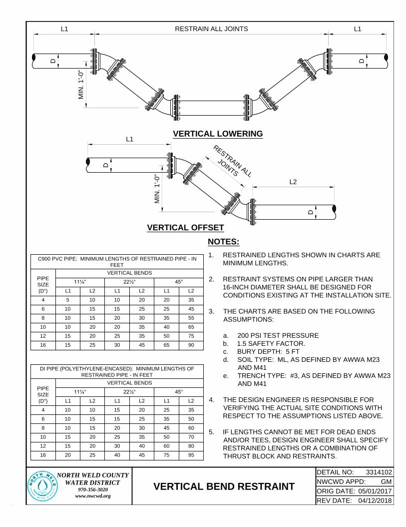
L1
VERTICAL OFFSET
L1 L1RESTRAIN ALL JOINTS
L2
R
E
S
T
R
A
I
N
A
L
L
J
O
I
N
T
S
VERTICAL LOWERING
MIN
. 1'-0"
MIN
. 1'-0"
D D
D
D
1. RESTRAINED LENGTHS SHOWN IN CHARTS ARE
MINIMUM LENGTHS.
2. RESTRAINT SYSTEMS ON PIPE LARGER THAN
16-INCH DIAMETER SHALL BE DESIGNED FOR
CONDITIONS EXISTING AT THE INSTALLATION SITE.
3. THE CHARTS ARE BASED ON THE FOLLOWING
ASSUMPTIONS:
a. 200 PSI TEST PRESSURE
b. 1.5 SAFETY FACTOR.
c. BURY DEPTH: 5 FT
d. SOIL TYPE: ML, AS DEFINED BY AWWA M23
AND M41
e. TRENCH TYPE: #3, AS DEFINED BY AWWA M23
AND M41
4. THE DESIGN ENGINEER IS RESPONSIBLE FOR
VERIFYING THE ACTUAL SITE CONDITIONS WITH
RESPECT TO THE ASSUMPTIONS LISTED ABOVE.
5. IF LENGTHS CANNOT BE MET FOR DEAD ENDS
AND/OR TEES, DESIGN ENGINEER SHALL SPECIFY
RESTRAINED LENGTHS OR A COMBINATION OF
THRUST BLOCK AND RESTRAINTS.
NOTES:
DI PIPE (POLYETHYLENE-ENCASED): MINIMUM LENGTHS OF
RESTRAINED PIPE - IN FEET
PIPE
SIZE
(D")
VERTICAL BENDS
11¼° 22½° 45°
L1 L2 L1 L2 L1 L2
4 10 10 15 20 25 35
6 10 15 15 25 35 50
8 10 15 20 30 45 60
10 15 20 25 35 50 70
12 15 20 30 40 60 80
16 20 25 40 45 75 95
C900 PVC PIPE: MINIMUM LENGTHS OF RESTRAINED PIPE - IN
FEET
PIPE
SIZE
(D")
VERTICAL BENDS
11¼° 22½° 45°
L1 L2 L1 L2 L1 L2
4 5 10 10 20 20 35
6 10 15 15 25 25 45
8 10 15 20 30 35 55
10 10 20 20 35 40 65
12 15 20 25 35 50 75
16 15 25 30 45 65 90
DETAIL NO:NORTH WELD COUNTYWATER DISTRICT
970-356-3020www.nwcwd.org
3314102
NORTH WELD
C
O
U
N
T
Y
W
A
TER
D
I
S
T
R
I
C
T
ESTABLISHED
1962
NWCWD APPD:
ORIG DATE:
REV DATE: 04/12/2018
05/01/2017
GM
VERTICAL BEND RESTRAINT

(THIS PAGE INTENTIONALLY LEFT BLANK)

NOTES:
MJ FITTING USED TO CONNECT TO AC
WATERLINE (VALVE, TEE, ETC.)
APPROVED TRANSITION COUPLING
(TYP). EITHER ROMAC 501 OR
ROMAC MACRO HP TRANSITION
COUPLING.
EXISTING
AC PIPE
EXISTING
AC PIPE
C900 PVC
WATERLINE (TYP)
1. ALL FITTINGS, VALVES, AND COUPLINGS SHALL BE POLYETHYLENE-ENCASED. PER
SECTION 33 05 20.
2. CONCRETE BLOCKING SHALL BE CENTERED UNDER FITTING AND INSTALLED ON
STABILIZATION MATERIAL, AS SHOWN.
MIN 4' FROM
EXISTING
AC COUPLING
(TYP)
4"
MIN
BEDDING DETAIL
PE
R
SP
EC
O
.
D
.
W
A
T
E
R
M
A
I
N
FLOWABLE
CONCRETE BACKFILL,
PER SECTION 31 23 25
PIP
E B
AS
E,
PE
R S
PE
C
NOTES:
1. REFER TO NWCWD'S STANDARD SPECIFICATIONS FOR ACCEPTABLE PARTS AND MATERIALS.
2. PIPE MAY BE BEDDED IN FLOWABLE CONCRETE BACKFILL, PER SECTION 31 23 25 AS AN ALTERNATIVE
TO CRUSHED STONE OR GRAVEL. SQUEEGEE SHALL NOT BE USED TO EMBED AC PIPE.
3. INSTALL DETECTABLE WARNING TAPE 2'-6" BELOW FINISHED GRADE, DIRECTLY OVER WATER MAIN.
REFER TO SECTION 33 14 10 FOR PRODUCT REQUIREMENTS.
ACTUAL SIDE SLOPE
BY CONTRACTOR
4" THICK LAYER OF 1
1
2
"
CRUSHED STONE, PER
SECTION 31 23 35
CONCRETE BLOCKS (MIN 4" THICK)
UNDER EACH TRANSITION
COUPLING, FITTING, VALVE, ETC.
CONCRETE BLOCKS (MIN 4" THICK)
UNDER EACH TRANSITION
COUPLING, FITTING, VALVE, ETC.
4" THICK LAYER OF 1
1
2
"
CRUSHED STONE, PER
SECTION 31 23 35
1
1
2
" CRUSHED STONE, PER
SECTION 31 23 35. SEE NOTE 2
DETAIL NO:NORTH WELD COUNTYWATER DISTRICT
970-356-3020www.nwcwd.org
3314103
NORTH WELD
C
O
U
N
T
Y
W
A
TER
D
I
S
T
R
I
C
T
ESTABLISHED
1962
NWCWD APPD:
ORIG DATE:
REV DATE: 04/12/2018
05/01/2017
GM
CONNECTION TO AC WATERLINE

(THIS PAGE INTENTIONALLY LEFT BLANK)

CA
UT
IO
N-W
AT
ER
LIN
E
TEST STATION WITHOUT GROUND ROD
TEST STATION WITH GROUND ROD
MARKER POST AND T-POST
PROVIDED BY NWCWD
3' T
O 3.5'
WATER PROOF
CONNECTIONS
TRACER WIRE, PER
SECTION 33 14 10
TAPED @ 2 POINTS ON
EACH JOINT OF PIPE
CABLE CLAMP
TO 6' COPPER
GROUND ROD
MARKER POST AND T-POST
PROVIDED BY NWCWD
3' T
O 3.5'
WATER PROOF
CONNECTIONS
TRACER WIRE, PER
SECTION 33 14 10
TAPED @ 2 POINTS ON
EACH JOINT OF PIPE
CA
UT
IO
N-W
AT
ER
LIN
E
WATERLINE
WATERLINE
DETAIL NO:NORTH WELD COUNTYWATER DISTRICT
970-356-3020www.nwcwd.org
3314104
NORTH WELD
C
O
U
N
T
Y
W
A
TER
D
I
S
T
R
I
C
T
ESTABLISHED
1962
NWCWD APPD:
ORIG DATE:
REV DATE: 04/12/2018
05/01/2017
GM
TRACER WIRE TEST STATION

(THIS PAGE INTENTIONALLY LEFT BLANK)

W
W
W
W
W
W
W
W
W
W
M
M
LO
T LIN
E
5 FT
(TYP)
R.O.W. LINE
INTERIOR UTILITY
EASEMENT LINE
CURB STOP, INSTALLED PER
DETAIL NO. 3314182 AND NOTE 3
METER PIT SET BY
NWCWD, SEE NOTE 1
STREET
WATERLINE
SERVICE LINE,
SEE NOTE 2
S
ID
E
W
A
L
K
1. REFER TO DETAIL NO. 3314183 FOR "METER PIT CONSTRUCTION ENVELOPE".
2. REFER TO DETAIL NO. 3314182 FOR "1-INCH SERVICE ASSEMBLY".
3. CURB STOP SHALL BE PLACED APPROXIMATELY EIGHT (8) FEET FROM INTERIOR UTILITY
EASEMENT LINE.
NOTES:
DETAIL NO:NORTH WELD COUNTYWATER DISTRICT
970-356-3020www.nwcwd.org
3314181
NORTH WELD
C
O
U
N
T
Y
W
A
TER
D
I
S
T
R
I
C
T
ESTABLISHED
1962
NWCWD APPD:
ORIG DATE:
REV DATE: 04/12/2018
05/01/2017
GM
WATER SERVICE LOCATION PLAN

(THIS PAGE INTENTIONALLY LEFT BLANK)

±8'-0"
4'-10" T
O 5'-0"
1" BALL
CORP STOP
TAPPING SADDLE
1" PE IPS CLASS 250
SIDR 7 SERVICE TUBING,
SEE NOTE 1
R.O
.W
.
TAPE END & CUT SMALL SLIT
IN TAPE AT 12 O'CLOCK ON
FACE OF CURB STOP TO
ALLOW AIR RELEASE
3" M
IN
1. USE INSERT STIFFENERS AT ALL COMPRESSION CONNECTIONS.
2. TIGHTEN ALL RESTRAINT BOLTS AT COMPRESSION CONNECTIONS.
3. ALL SERVICES SHALL BE BEDDED IN APPROVED "BEDDING ZONE MATERIALS," FROM MAIN TO
CURB STOP, PER SECTION 31 23 35.
4. ALL TAPPING SADDLES, CORP STOPS, CURB STOPS, SERVICE LINE AND FITTINGS SHALL
CONFORM TO SECTION 33 14 18 - SERVICE LINES AND APPURTENANCES.
5. NO SUBSTITUTES OF "EQUALS" WITHOUT WRITTEN APPROVAL FROM NWCWD.
MARK CURB BOX WITH
4X4 POST, EXPOSED 3 FT
ABOVE GRADE
NOTES:
WATER MAIN
CURB STOP BOX
PER SECTION
33 14 18
CURB STOP WITH
INVERTED KEY INSTALLED
ON CONCRETE BLOCK
TRACER WIRE, PER
SECTION 33 14 10
TYPICAL 15' UTILITY EASEMENT
DETAIL NO:NORTH WELD COUNTYWATER DISTRICT
970-356-3020www.nwcwd.org
3314182
NORTH WELD
C
O
U
N
T
Y
W
A
TER
D
I
S
T
R
I
C
T
ESTABLISHED
1962
NWCWD APPD:
ORIG DATE:
REV DATE: 04/12/2018
05/01/2017
GM
1-INCH SERVICE ASSEMBLY

(THIS PAGE INTENTIONALLY LEFT BLANK)

4 F
T M
AX
4 FT WIDE x 8 FT LONG
METER PIT CONSTRUCTION
ENVELOPE
PROPOSED CURBSTOP
(TYPICAL NON-POTABLE)
PROPOSED METER PIT
EXISTING CURBSTOP
(ONLY IN SUBDIVISIONS)
EXISTING SERVICE
LINE FROM MAIN
SERVICE LINE TO CUSTOMER;
CONNECTION IS 1" FNPT
1. AT TIME OF METER PIT INSTALLATION, EXISTING GRADE MUST BE WITHIN 12" OF FINAL LOT GRADE. A
STAKE OR STRING LINE SHALL BE USED TO INDICATE FINAL GRADE SO METER PIT CAN BE SET TO
PROPER ELEVATION.
2. METER PIT CONSTRUCTION ENVELOPE SHALL NOT BE PLACED WITHIN A HARD SURFACE DRIVEWAY OR
SIDEWALK TO FACILITATE EASE OF MAINTENANCE.
3. ONLY GRASS, LANDSCAPE ROCK, OR BARK MAY COVER THE METER PIT CONSTRUCTION ENVELOPE. DO
NOT PLACE TREES, SHRUBS, BUSHES OR OTHER EXPENSIVE TO REPLACE LANDSCAPE OVER
CONSTRUCTION ENVELOPE.
NOTES:
CONNECTION TO CUSTOMER
SERVICE IS
3
4
" MNPT
DETAIL NO:NORTH WELD COUNTYWATER DISTRICT
970-356-3020www.nwcwd.org
3314183
NORTH WELD
C
O
U
N
T
Y
W
A
TER
D
I
S
T
R
I
C
T
ESTABLISHED
1962
NWCWD APPD:
ORIG DATE:
REV DATE: 04/12/2018
05/01/2017
GMMETER PIT CONSTRUCTION
ENVELOPE

(THIS PAGE INTENTIONALLY LEFT BLANK)

CLOSE - RIGHT,
CLOCKWISE
OPEN - LEFT,
COUNTER-CLOCKWISE
12
11
10
9
8
7
6
5
4
3
2
1
OPERATING
NUT
PLAN OF VALVE
NOTES:
1. REFER TO NWCWD'S STANDARD SPECIFICATIONS FOR ACCEPTABLE PARTS AND
MATERIALS.
2. NWCWD VALVES OPEN COUNTER-CLOCKWISE (BLACK NUT) AND CLOSE CLOCKWISE.
3. VALVES WITH RED NUTS TYPICALLY OPEN RIGHT (CLOCKWISE) AND ARE NOT USED
WITHIN NWCWD'S SERVICE AREA.
4. REFER TO SECTION 33 14 22 FOR HYDRANT REQUIREMENTS.
DETAIL NO:NORTH WELD COUNTYWATER DISTRICT
970-356-3020www.nwcwd.org
3314201
NORTH WELD
C
O
U
N
T
Y
W
A
TER
D
I
S
T
R
I
C
T
ESTABLISHED
1962
NWCWD APPD:
ORIG DATE:
REV DATE: 04/12/2018
05/01/2017
GM
TYPICAL VALVE OPERATION

(THIS PAGE INTENTIONALLY LEFT BLANK)

18"x18"x6" THICK
CONCRETE
COLLAR, SEE PLAN
ANGLE CUT OR DRILL
HOLE IN VALVE BOX
FOR TRACER WIRES
TOP OF VALVE BOX SHALL BE
SET
1
8
" TO
1
2
" BELOW ASPHALT
TRACER WIRES
LEADING FROM PIPE
TO VALVE BOX
VALVE BOX,
SEE NOTE 3
TAPE
VALVE BLOCKING
BACKFILL IN 6"
LAYERS AND
TAMP
2" SQUARE
OPERATING NUT,
SEE NOTE 3
TRENCH
BACKFILL
MATERIAL, PER
SECTION 31 23 35
DUCTILE IRON LID
MARKED "WATER"
FINISHED
GRADE
HAND BACKFILL
IN 3" LAYERS
AND TAMP
VALVE BOX
SUPPORT BLOCKING
SECTION A-A
NOTE 4
NOTE 4
A
A
1. VALVE BOX SHALL BE CENTERED AND PLUMB OVER THE OPERATING NUT AND SHALL NOT TRANSMIT
SHOCK WAVES OR STRESS TO THE VALVE.
2. VALVE SHALL BE BLOCKED WITH POURED CONCRETE, BRICK, OR OTHER SUITABLE MASONRY
MATERIAL.
3. GATE VALVE AND VALVE BOX, PER SECTION 33 14 20. IF DEPTH IS GREATER THAN FIVE (5) FEET,
INSTALL STEM EXTENSION TO FOUR (4) FEET BELOW GRADE.
4. WRAP VALVE AND VALVE BOX WITH POLYETHYLENE ENCASEMENT, PER DETAIL NO. 3305202.
5. TRACER WIRE SHALL BE TERMINATED IN VALVE BOX, AS SHOWN. REFER TO SECTION 33 14 10 FOR
REQUIREMENTS.
NOTES:
DETAIL NO:NORTH WELD COUNTYWATER DISTRICT
970-356-3020www.nwcwd.org
3314202
NORTH WELD
C
O
U
N
T
Y
W
A
T
ER
D
I
S
T
R
I
C
T
ESTABLISHED
1962
NWCWD APPD:
ORIG DATE:
REV DATE: 04/12/2018
05/01/2017
GM
GATE VALVE AND BOX
1'-6"
1'-6
"
VALVE BOX LID
9"
9"
PLAN
CONCRETE COLLAR ONLY
REQ'D FOR INSTALLATIONS IN
ASPHALT PAVEMENT

(THIS PAGE INTENTIONALLY LEFT BLANK)

2'-0"
1. ALL FITTINGS TO HAVE MECHANICAL LUG RESTRAINT.
2. ALL BURIED DIP TO BE POLYETHYLENE-ENCASED.
3. BLOWOFF RISER SHALL BE PAINTED "BLUE" FOR POTABLE
WATER OR "PURPLE" FOR NON-POTABLE.
4. DIP RISER AND FLANGED TEE SHALL HAVE POLYURETHANE OR
FUSION-BONDED EPOXY LINING.
5. COAT ALL (BURIED AND EXPOSED) IRON VALVES, FITTINGS, AND
PIPING WITH FUSION-BONDED EPOXY.
1" FNPTxPEP CURB
STOP: INSTALL
STREET 90° ELBOW,
POINTED DOWN
1" TAPPED MJ PLUG
MIN. 2' OF 1" PE SERVICE
TUBING W/ ONE (1) 1"
MNPTxCOMP COUPLING
CURB STOP BOX: IF
DEPTH IS GREATER
THAN 6', INSTALL KEY
EXTENSION TO 4' BELOW
GRADE
DIP RISER PIPE, FLGxPE,
CUT TO LENGTH IN FIELD
2'-0"
SUPPORT
BLOCK (TYP)
MJ
TEE
MJ GATE
VALVE
VALVE BOX: IF DEPTH IS GREATER
THAN 5', INSTALL STEM EXTENSION
TO 4' BELOW GRADE
WATER MAIN
OUTLET MJ TEE (ROLLED
DOWN AT 45°) OR
TANGENTIAL WELDED
OUTLET FITTING
45° MJ ELBOW
(NOT NEEDED IF
WELDED OUTLET
IS USED)
DIP
2' T
O 3'
6"
1
1
2
" CRUSHED STONE (18" MIN),
PER SECTION 31 23 35
FLANGED TEE
NOTES:
BLIND FLANGE W/ 2" FNPT HOLE x
2.5" FIRE HOSE THREAD ADAPTER
W/ FIRE HYDRANT CAP ON END
PLAIN BLIND FLANGE
MAIN SIZE BLOWOFF SIZE
6" TO 8" 4"
12" TO 18" 6"
20" TO 30" 8"
36" & LARGER 12"
DETAIL NO:NORTH WELD COUNTYWATER DISTRICT
970-356-3020www.nwcwd.org
3314203
NORTH WELD
C
O
U
N
T
Y
W
A
TER
D
I
S
T
R
I
C
T
ESTABLISHED
1962
NWCWD APPD:
ORIG DATE:
REV DATE: 04/12/2018
05/01/2017
GM4-INCH TO 12-INCH
BLOWOFF ASSEMBLY

(THIS PAGE INTENTIONALLY LEFT BLANK)
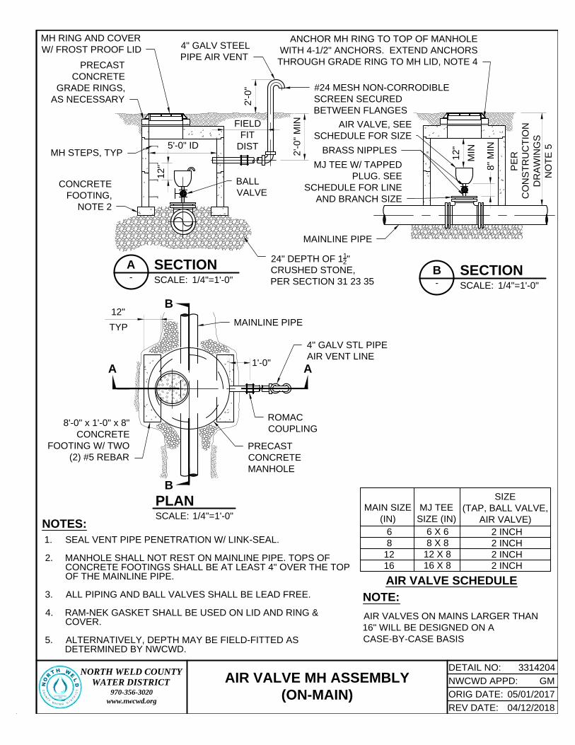
12"
TYP
5'-0" ID
1'-0"
2'-0" M
IN
12"
2'-0"
1. SEAL VENT PIPE PENETRATION W/ LINK-SEAL.
2. MANHOLE SHALL NOT REST ON MAINLINE PIPE. TOPS OF
CONCRETE FOOTINGS SHALL BE AT LEAST 4" OVER THE TOP
OF THE MAINLINE PIPE.
3. ALL PIPING AND BALL VALVES SHALL BE LEAD FREE.
4. RAM-NEK GASKET SHALL BE USED ON LID AND RING &
COVER.
5. ALTERNATIVELY, DEPTH MAY BE FIELD-FITTED AS
DETERMINED BY NWCWD.
MAIN SIZE
(IN)
SIZE
(TAP, BALL VALVE,
AIR VALVE)
MJ TEE
SIZE (IN)
FIELD
FIT
DIST
2 INCH
2 INCH
2 INCH
6 X 6
8 X 8
12 X 8
6
8
12
PE
R
CO
NS
TR
UC
TIO
N
DR
AW
IN
GS
NO
TE
5
8" M
IN
ANCHOR MH RING TO TOP OF MANHOLE
WITH 4-1/2" ANCHORS. EXTEND ANCHORS
THROUGH GRADE RING TO MH LID, NOTE 4
AIR VALVE, SEE
SCHEDULE FOR SIZE
BRASS NIPPLES
MJ TEE W/ TAPPED
PLUG. SEE
SCHEDULE FOR LINE
AND BRANCH SIZE
12"
MIN
4" GALV STEEL
PIPE AIR VENT
#24 MESH NON-CORRODIBLE
SCREEN SECURED
BETWEEN FLANGES
MH RING AND COVER
W/ FROST PROOF LID
PRECAST
CONCRETE
GRADE RINGS,
AS NECESSARY
MH STEPS, TYP
CONCRETE
FOOTING,
NOTE 2
BALL
VALVE
MAINLINE PIPE
4" GALV STL PIPE
AIR VENT LINE
8'-0" x 1'-0" x 8"
CONCRETE
FOOTING W/ TWO
(2) #5 REBAR
PRECAST
CONCRETE
MANHOLE
ROMAC
COUPLING
NOTES:
AIR VALVES ON MAINS LARGER THAN
16" WILL BE DESIGNED ON A
CASE-BY-CASE BASIS
NOTE:
AIR VALVE SCHEDULE
24" DEPTH OF 1
1
2
"
CRUSHED STONE,
PER SECTION 31 23 35
2 INCH16 X 816
SCALE:
SECTION
1/4"=1'-0"
A
-
SCALE:
SECTION
1/4"=1'-0"
B
-
SCALE:
PLAN
1/4"=1'-0"
A A
B
B
MAINLINE PIPE
DETAIL NO:NORTH WELD COUNTYWATER DISTRICT
970-356-3020www.nwcwd.org
3314204
NORTH WELD
C
O
U
N
T
Y
W
A
TE
R
D
I
S
T
R
I
C
T
ESTABLISHED
1962
NWCWD APPD:
ORIG DATE:
REV DATE: 04/12/2018
05/01/2017
GM
AIR VALVE MH ASSEMBLY
(ON-MAIN)

(THIS PAGE INTENTIONALLY LEFT BLANK)

1'-0"
2'-0"
MIN
12"
MIN
2'-0"
1. SEAL VENT PIPE PENETRATION W/ LINK-SEAL.
2. ALL 2" PIPING AND BALL VALVES SHALL BE LEAD FREE.
3. HOLE LOCATION TBD IN-FIELD. SEAL ANNULUS AROUND PIPE W/
MORTAR; NO LINK-SEAL.
4. #24 MESH NON-CORRODIBLE SCREEN SECURED BETWEEN
FLANGES.
5. LIGHT-WELDED STEEL BRACKET (ANVIL FIG. 194) W/ ADJUSTABLE
PIPE SADDLE WITH U-BOLT (ANVIL FIG. 191). BOTH W/ GALVANIZED
FINISH, ANCHORED TO MH WALL W/ SST HARDWARE.
MAIN SIZE
(IN)
SIZE
(TAP, BALL VALVE,
AIR VALVE, ETC.)
FIELD
FIT
DIST
NOTE 4
MH RING AND COVER
W/ FROST PROOF LID
PRECAST CONCRETE GRADE
RING, 2 MAX OR FIELD-FITTED
AS DETERMINED BY NWCWD
MH STEPS, TYP
CONCRETE
FOOTING, TYP
BALL VALVE
MAINLINE PIPE
4" GALV STL
AIR VENT
PIPING &
FITTINGS
8'-0" x 1'-0" x 8"
CONCRETE
FOOTING W/ TWO
(2) #5 REBAR, TYP
PRECAST CIRCULAR
CONCRETE MANHOLE
(60" I.D.)
ROMAC
COUPLING
NOTES:
AIR VALVES ON MAINS
LARGER THAN 16" WILL BE
DESIGNED ON A
CASE-BY-CASE BASIS
AIR VALVE SCHEDULE
12"
TY
P
24" DEPTH OF 1
1
2
" CRUSHED STONE,
PER SECTION 31 23 35
AIR VALVE, PER
SCHEDULE
TAPPING SADDLE W/ CORP
STOP & 90° STREET ELBOW
CURB STOP W/ SERVICE BOX
DISTANCE VARIES; REFER TO PLAN & PROFILE DWGS
1
8
" PER FOOT RISE, MIN.
12"
BRACKET & ADJ PIPE STANCHION
SADDLE, PER NOTE 5
SCALE:
PLAN
1/4"=1'-0"
SCALE:
SECTION
1/4"=1'-0"
A
-
A A
FIELD-CORED HOLE, NOTE 3
2 INCH
2 INCH
2 INCH
6
8
12
16
2 INCH
SIDR 7 PEP ONLY
*
*
DETAIL NO:NORTH WELD COUNTYWATER DISTRICT
970-356-3020www.nwcwd.org
3314205
NORTH WELD
C
O
U
N
T
Y
W
A
TER
D
I
S
T
R
I
C
T
ESTABLISHED
1962
NWCWD APPD:
ORIG DATE:
REV DATE: 04/12/2018
05/01/2017
GM
AIR VALVE MH ASSEMBLY
(OFF-MAIN)

(THIS PAGE INTENTIONALLY LEFT BLANK)
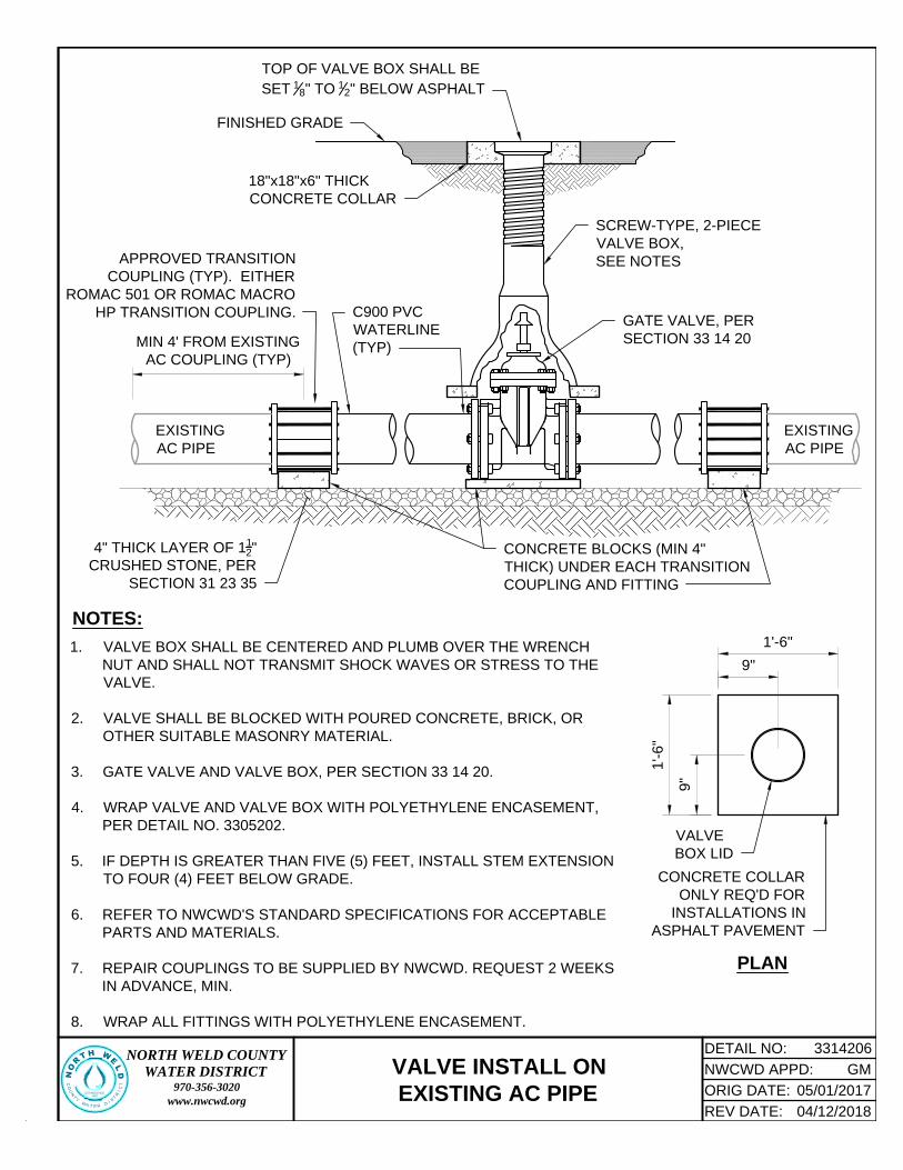
18"x18"x6" THICK
CONCRETE COLLAR
TOP OF VALVE BOX SHALL BE
SET
1
8
" TO
1
2
" BELOW ASPHALT
SCREW-TYPE, 2-PIECE
VALVE BOX,
SEE NOTES
FINISHED GRADE
APPROVED TRANSITION
COUPLING (TYP). EITHER
ROMAC 501 OR ROMAC MACRO
HP TRANSITION COUPLING.
EXISTING
AC PIPE
C900 PVC
WATERLINE
(TYP)
CONCRETE BLOCKS (MIN 4"
THICK) UNDER EACH TRANSITION
COUPLING AND FITTING
MIN 4' FROM EXISTING
AC COUPLING (TYP)
GATE VALVE, PER
SECTION 33 14 20
EXISTING
AC PIPE
4" THICK LAYER OF 1
1
2
"
CRUSHED STONE, PER
SECTION 31 23 35
1. VALVE BOX SHALL BE CENTERED AND PLUMB OVER THE WRENCH
NUT AND SHALL NOT TRANSMIT SHOCK WAVES OR STRESS TO THE
VALVE.
2. VALVE SHALL BE BLOCKED WITH POURED CONCRETE, BRICK, OR
OTHER SUITABLE MASONRY MATERIAL.
3. GATE VALVE AND VALVE BOX, PER SECTION 33 14 20.
4. WRAP VALVE AND VALVE BOX WITH POLYETHYLENE ENCASEMENT,
PER DETAIL NO. 3305202.
5. IF DEPTH IS GREATER THAN FIVE (5) FEET, INSTALL STEM EXTENSION
TO FOUR (4) FEET BELOW GRADE.
6. REFER TO NWCWD'S STANDARD SPECIFICATIONS FOR ACCEPTABLE
PARTS AND MATERIALS.
7. REPAIR COUPLINGS TO BE SUPPLIED BY NWCWD. REQUEST 2 WEEKS
IN ADVANCE, MIN.
8. WRAP ALL FITTINGS WITH POLYETHYLENE ENCASEMENT.
NOTES:
DETAIL NO:NORTH WELD COUNTYWATER DISTRICT
970-356-3020www.nwcwd.org
3314206
NORTH WELD
C
O
U
N
T
Y
W
A
TER
D
I
S
T
R
I
C
T
ESTABLISHED
1962
NWCWD APPD:
ORIG DATE:
REV DATE: 04/12/2018
05/01/2017
GMVALVE INSTALL ON
EXISTING AC PIPE
1'-6"
1'-6
"
VALVE
BOX LID
9"
9"
PLAN
CONCRETE COLLAR
ONLY REQ'D FOR
INSTALLATIONS IN
ASPHALT PAVEMENT

(THIS PAGE INTENTIONALLY LEFT BLANK)

VALVE BOX: IF DEPTH IS GREATER THAN FIVE
(5) FEET, INSTALL STEM EXTENSION TO FOUR
(4) FEET BELOW GRADE, SEE NOTE 3
VALVE OPERATOR ON
NORTH OR WEST SIDE
OF PIPE, ONLY
VALVE BOX SUPPORT BLOCKING,
SEE NOTE 2
BFV, SEE
NOTE 3
CONCRETE FOUNDATION BLOCK MINIMUM
THICKNESS OF 6" FOR FULL LENGTH AND WIDTH
OF BUTTERFLY VALVE. POLYETHYLENE-ENCASE
VALVE TO PROTECT FROM CONCRETE
18"x18"x6" THICK
CONCRETE COLLAR,
SEE PLAN
TOP OF VALVE BOX SHALL BE
SET
1
8
" TO
1
2
" BELOW ASPHALT
FINISHED GRADE
TRACER WIRES,
SEE NOTE 5
2" SQUARE OPERATING NUT,
SEE NOTES 1 & 3
ANGLE-CUT OR DRILL HOLE IN
VALVE BOX FOR TRACER WIRES
1
1
2
" CRUSHED STONE (MIN. 12" THICK), PER
SECTION 31 23 35, UNDER 6" BLOCK; CONTINUE
BEDDING MATERIAL TO VALVE BOX SUPPORT
BLOCKING
DISTANCE VARIES
1. VALVE BOX SHALL BE CENTERED AND PLUMB OVER THE
OPERATING NUT AND SHALL NOT TRANSMIT SHOCK
WAVES OR STRESS TO THE VALVE.
2. VALVE SHALL BE BLOCKED WITH POURED CONCRETE,
BRICK, OR OTHER SUITABLE MASONRY MATERIAL.
3. BUTTERFLY VALVE AND VALVE BOX, PER SECTION 33 14 20.
4. WRAP VALVE AND VALVE BOX WITH POLYETHYLENE
ENCASEMENT, PER DETAIL NO. 3305202.
5. TRACER WIRE SHALL BE TERMINATED IN VALVE BOX, AS
SHOWN. REFER TO SECTION 33 14 10 FOR REQUIREMENTS.
NOTES:
DETAIL NO:NORTH WELD COUNTYWATER DISTRICT
970-356-3020www.nwcwd.org
3314207
NORTH WELD
C
O
U
N
T
Y
W
A
TE
R
D
I
S
T
R
I
C
T
ESTABLISHED
1962
NWCWD APPD:
ORIG DATE:
REV DATE: 04/12/2018
05/01/2017
GM
BUTTERFLY VALVE AND BOX
1'-6"
1'-6"
VALVE
BOX
LID
9"
9"
PLAN
CONCRETE COLLAR ONLY
REQ'D FOR INSTALLATIONS
IN ASPHALT PAVEMENT

(THIS PAGE INTENTIONALLY LEFT BLANK)

1
1
2
" CRUSHED STONE, PER
SECTION 31 23 35 (1 CY,
MIN.; 18" DEEP, MIN.)
BOND BREAKER
(POLYETHYLENE
ENCASEMENT)
3-WAY DRY-BARREL FIRE
HYDRANT, PER SECTION 33 14 22
TOP OF GRAVEL 3" MIN
ABOVE DRAIN HOLE
6" DIP; WRAPPED IN POLYETHYLENE
ENCASEMENT OR C-900, DR14 PVC
FROM TEE ON THE MAIN TO THE
HYDRANT; RESTRAIN ALL JOINTS.
VALVE BLOCKING
6" MJ GATE VALVE
W/ MEGALUGS
CARE TO BE TAKEN
TO PREVENT
PLUGGING OF FIRE
HYDRANT DRAIN
SWIVEL
HYDRANT
TEE
2' MIN
2" T
O 4"
HYDRANT BLOCKING
WRAP HYDRANT BARREL
FROM HYDRANT SHOE
TO FINISHED GRADE W/
POLYETHYLENE
ENCASEMENT, NOTE 3
SLOPE FINISHED GRADE AWAY
FROM HYDRANT AT 2%, MIN.
18"x18"x6" THICK
CONCRETE COLLAR
TOP OF VALVE BOX
SHALL BE SET
1
8
" TO
1
2
"
BELOW ASPHALT
TRACER WIRE
LEADING FROM
PIPE TO TEST
STATION
VALVE BOX, PER
SECTION 33 14 20
FINISHED
GRADE
POURED
THRUST
BLOCK
1. TEST STATION AND TRACER WIRE, PER SECTION 33 14 10.
2. TOP OF TEST STATION SHALL BE
1
8
" -
1
2
" ABOVE FINISHED GRADE.
3. CUT SLITS IN BASE OF POLYETHYLENE ENCASEMENT TO ALLOW FOR DRAINAGE.
NOTES:
TEST STATION;
SET BEHIND
HYDRANT, SEE
NOTES 1 & 2
DETAIL NO:NORTH WELD COUNTYWATER DISTRICT
970-356-3020www.nwcwd.org
3314221
NO
RTH WELD
C
O
U
N
T
Y
W
A
T
ER
D
I
S
T
R
I
C
T
ESTABLISHED
1962
NWCWD APPD:
ORIG DATE:
REV DATE: 04/12/2018
05/01/2017
GM
FIRE HYDRANT ASSEMBLY

(THIS PAGE INTENTIONALLY LEFT BLANK)

2" KUPFERLE
MAINGUARD #77
HYDRANT, PER
SECTION 33 14 22
TRACER WIRE, PER
SECTION 33 14 10
MJ CAP TAPPED
2", PER SECTION
33 05 20
MAINGUARD 2"
POST HYDRANT
2" RW THREADED GV
WITH 2" OPERATING
NUT, PER SECTION
33 14 20; SEE NOTE 3
WEEP
HOLE
2" BRASS 90°
STREET ELBOW
2" BRASS
NIPPLE (MIN.
24" LONG,
NOTE 6)
CONCRETE BLOCK
RESTRAIN WATER MAIN
AS A DEAD END, PER
DETAIL NO. 3314101
2" BRASS NIPPLE (MIN.
24" LONG, NOTE 6)
TRACER WIRE TO
TEST STATION
2" BRASS
TAPPING
SLEEVE, PER
SECTION
33 05 10
2" RW THREADED GV WITH
2" OPERATING NUT, PER
SECTION 33 14 20, NOTE 3
END-OF-MAIN
ON-MAIN
1
1
2
" CRUSHED STONE,
PER SECTION 31 23 35
(1 CY MIN.; 18" DEEP,
MIN.)
NOTES:
1. TEST STATION AND TRACER WIRE, PER SECTION 33 14 10.
2. TOP OF TEST STATION SHALL BE SET
1
8
" -
1
2
" ABOVE FINISHED GRADE.
3. 2" GATE VALVE IS NOT REQ'D IF DISTANCE FROM THE WATERMAIN TO THE FLUSHING HYDRANT IS 20
FT., OR LESS - AND - THERE IS A VALVE AT THE MAIN FOR ISOLATION.
4. WRAP ALL BURIED METAL W/ POLYETHYLENE ENCASEMENT.
5. CUT SLITS IN BASE OF POLYETHYLENE ENCASEMENT TO ALLOW FOR DRAINAGE.
6. FIELD FIT, IF APPLICABLE.
WATERLINE
TEST STATION,
SET BEHIND
HYDRANT, SEE
NOTES 1 & 2
2" BRASS PIPING,
LENGTH TBD IN FIELD
CURB STOP BOX PER
SECTION 33 14 18
SEE "END-OF-MAIN" FOR CONT.
OF CURB STOP BOX, HYDRANT,
TRACER WIRE. ETC.
2" BRASS CLOSE NIPPLE
2" BRASS 90°
STREET ELBOW
WEEP HOLE
1
1
2
" CRUSHED STONE,
PER SECTION 31 23 35
(1 CY MIN.; 18" DEEP,
MIN.)
WATERLINE
DETAIL NO:NORTH WELD COUNTYWATER DISTRICT
970-356-3020www.nwcwd.org
3314222
NORTH WELD
C
O
U
N
T
Y
W
A
TER
D
I
S
T
R
I
C
T
ESTABLISHED
1962
NWCWD APPD:
ORIG DATE:
REV DATE: 04/12/2018
05/01/2017
GM
2-INCH BLOWOFF ASSEMBLY

(THIS PAGE INTENTIONALLY LEFT BLANK)

(THIS PAGE INTENTIONALLY LEFT BLANK)

North Weld County Water District32825 WCR 39Lucerne, Colorado 80646