Embed Size (px)
Citation preview

___________________________________________________________________________________________________
OPR: HQ AFCESA/CEXR (Mr Joseph H. Smith) Certified by: HQ AFCESA/CC (Col H. Dean Bartel)Pages: 283/Distribution: F
BY ORDER OF THE AIR FORCE PAMPHLET 10-219, VOLUME 3SECRETARY OF THE AIR FORCE 1 APRIL 1997
Operations
POSTATTACK AND POSTDISASTER PROCEDURES
NOTICE: This publication is available digitally on the SAF/AAD WWW site at: http://afpubs.hq.af.mil. If you lackaccess, contact your Publishing Distribution Office (PDO).
This volume in this pamphlet series provides base civil engineers with information and guidance for the execution ofcontingency response activities. It describes procedures to be used for a rapid transition from routine, day-to-day operationsto an emergency response posture. Using the predisaster planning and preparation procedures of Volumes 1 and 2 as itsbasis, this volume gives definitions; describes duties; lists organization, equipment, and materials; and tells how work isaccomplished to ensure recovery and continued operation of the air base during and after a crisis. This pamphlet seriessupports AFI 10-210, Prime Base Engineer Emergency Force Program and AFI 10-211, Civil Engineer ContingencyResponse Planning. Send comments and suggested improvements to HQ AFCESA/CEX, 139 Barnes Drive, Tyndall AFBFL 32403-5319.
ParagraphChapter 1--Introduction References, Abbreviations, Acronyms, and Terms ........................................................................................... 1.1 Purpose............................................................................................................................................................ 1.2 Scope............................................................................................................................................................... 1.3 Situation.......................................................................................................................................................... 1.4
Chapter 2--Command and Control Introduction..................................................................................................................................................... 2.1 Overview......................................................................................................................................................... 2.2 Command and Control Concepts ..................................................................................................................... 2.3 Leadership and Management ........................................................................................................................... 2.4 Concept Relationships ..................................................................................................................................... 2.5 Unity of Purpose .............................................................................................................................................. 2.6 Knowledge ...................................................................................................................................................... 2.7 Strategy and Direction ..................................................................................................................................... 2.8 Base Recovery Chain of Command .................................................................................................................. 2.9 SRC Functions................................................................................................................................................. 2.10 BCE Damage Control Center Functions........................................................................................................... 2.11 Alternate SRC/DCC Data Requirements.......................................................................................................... 2.12 Initial Base Recovery Activities ....................................................................................................................... 2.13 Command and Control Communications ......................................................................................................... 2.14 Continuity of Command and Control ............................................................................................................... 2.15 Summary......................................................................................................................................................... 2.16
Chapter 3--Common Actions and Concepts Introduction..................................................................................................................................................... 3.1 Overview......................................................................................................................................................... 3.2 Dispersal Actions ............................................................................................................................................ 3.3 Radiological Shelter Monitoring...................................................................................................................... 3.4 Nuclear Accident Response.............................................................................................................................. 3.5 Chemical and Biological Monitoring ............................................................................................................... 3.6Personnel Accountability ................................................................................................................................... 3.7
2 AFPAM 10-219 Volume 3 1 April 1997
Emergency Teams ........................................................................................................................................... 3.8 Summary......................................................................................................................................................... 3.9
Chapter 4--Explosive Ordnance Reconnaissance Introduction..................................................................................................................................................... 4.1 Overview......................................................................................................................................................... 4.2 Types of Explosive Ordnance........................................................................................................................... 4.3 Explosive Ordnance Reconnaissance ............................................................................................................... 4.4 Explosive Ordnance Disarmament and Removal.............................................................................................. 4.5 Mass Ordnance Clearance ............................................................................................................................... 4.6 Summary......................................................................................................................................................... 4.7
Chapter 5--Chemical Defense Activities Introduction..................................................................................................................................................... 5.1 Overview......................................................................................................................................................... 5.2 Chemical Agents ............................................................................................................................................. 5.3 Individual Personnel Protection ....................................................................................................................... 5.4 Collective Personnel Protection........................................................................................................................ 5.5 Decontamination Equipment and Material....................................................................................................... 5.6 Personnel Decontamination ............................................................................................................................. 5.7 Area Decontamination..................................................................................................................................... 5.8 Vehicle Decontamination ................................................................................................................................ 5.9 Summary......................................................................................................................................................... 5.10
Chapter 6--Damage Assessment Procedures Introduction..................................................................................................................................................... 6.1 Overview......................................................................................................................................................... 6.2 Damage Assessment and Response Team Operations....................................................................................... 6.3 Team Composition and Leadership.................................................................................................................. 6.4 Equipment....................................................................................................................................................... 6.5 Assessment Technique..................................................................................................................................... 6.6 Initial Reconnaissance (Phase I) ...................................................................................................................... 6.7 Detailed Reconnaissance (Phase II).................................................................................................................. 6.8 Damage Recording and Reporting ................................................................................................................... 6.9 Summary......................................................................................................................................................... 6.10
Chapter 7--Expedient Facility and Utility Repair Introduction..................................................................................................................................................... 7.1 Overview......................................................................................................................................................... 7.2 Repair Considerations...................................................................................................................................... 7.3 CONUS Versus Theater Repairs ...................................................................................................................... 7.4 Damage Assessment Overview ........................................................................................................................ 7.5 Restoration of Runway Ancillary Equipment ................................................................................................... 7.6 Expedient Utility Repairs................................................................................................................................. 7.7 Shallow Well Construction .............................................................................................................................. 7.8 Expedient Facility Repairs ............................................................................................................................... 7.9 Debris Removal ............................................................................................................................................... 7.10 Portable Area Lighting .................................................................................................................................... 7.11 Summary......................................................................................................................................................... 7.12
Chapter 8--Aircraft Arresting Systems Introduction..................................................................................................................................................... 8.1 Overview......................................................................................................................................................... 8.2 Mobile Aircraft Arresting System .................................................................................................................... 8.3 Expeditionary Systems..................................................................................................................................... 8.4 Summary......................................................................................................................................................... 8.5Chapter 9--Mobile Airfield Lighting Systems Introduction..................................................................................................................................................... 9.1
AFPAM 10-219 Volume 3 1 April 1997 3
Overview......................................................................................................................................................... 9.2 Characteristics of Airfield Lighting Systems.................................................................................................... 9.3 Potential Conditions Necessitating Mobile Airfield Lighting Use..................................................................... 9.4 Mobile Airfield Lighting Systems............................................................................................. ....................... 9.5 Wartime Installation Considerations................................................................................................................ 9.6 Summary...................................................................................................................... ................................... 9.7
Chapter 10--Fire Suppression and Emergency Response Introduction..................................................................................................................................................... 10.1 Overview......................................................................................................................................................... 10.2 Fire Suppression Roles and Responsibilities..................................................................................................... 10.3 Fire Protection Manning, Equipment, and Extinguishing Agents..................................................................... 10.4 Fire Protection Operations ............................................................................................................................... 10.5 Auxiliary Firefighting...................................................................................................................................... 10.6 Search and Rescue (SAR) Concepts ................................................................................................................. 10.7 Summary ........................................................................................................................................................ 10.8
Chapter 11--Operation, Maintenance and Follow-On Repair of Essential Services,Facilities and Equipment Introduction..................................................................................................................................................... 11.1 Overview......................................................................................................................................................... 11.2 O&M Considerations....................................................................................................................................... 11.3 Airfield Ancillary Equipment O&M ................................................................................................................ 11.4 Utility Repairs ................................................................................................................................................. 11.5 Facilities and Services ..................................................................................................................................... 11.6 Alternate Transportation Routes ...................................................................................................................... 11.7 Resupply and Stockpiling ................................................................................................................................ 11.8 Summary......................................................................................................................................................... 11.9
Chapter 12--Security Activities Introduction..................................................................................................................................................... 12.1 Overview......................................................................................................................................................... 12.2 Threats to US Air Force Bases ......................................................................................................................... 12.3 Security Planning ............................................................................................................................................ 12.4 Antiterrorism Planning.................................................................................................................................... 12.5 Summary......................................................................................................................................................... 12.6
Chapter 13--Base Denial Introduction..................................................................................................................................................... 13.1 Overview......................................................................................................................................................... 13.2 Base Denial Considerations ............................................................................................................................. 13.3 Conventional Base Denial Methods ................................................................................................................. 13.4 Base Denial Responsibilities and Techniques................................................................................................... 13.5 Withdrawal and Evacuation............................................................................................................................. 13.6 Summary......................................................................................................................................................... 13.7
PageFigures1.1 Damage Assessment Plotting ................................................................................................................................. 82.1 BRAAT Organization .......................................................................................................................................... 123.1 Alpha Radiation .................................................................................................................................................. 173.2 Beta Radiation ..................................................................................................................................................... 183.3 Gamma Radiation ................................................................................................................................................ 183.4 Distance as a Protective Factor ............................................................................................................................. 193.5 Relative Shielding Efficiency of Various Materials............................................................................................... 203.6 Dispensing Chemical and Biological Agents........................................................................................................ 213.7 M8 Chemical Agent Detector Paper ..................................................................................................................... 22

4 AFPAM 10-219 Volume 3 1 April 1997
3.8 M9 Chemical Agent Detector Paper ..................................................................................................................... 233.9 M256 Chemical Agent Detector Kit ..................................................................................................................... 233.10 M8A1 System Components.................................................................................................................................. 244.1 Unexploded Ordnance.......................................................................................................................................... 324.2 Common Bombs .................................................................................................................................................. 334.3 Mortars and Rockets ............................................................................................................................................ 344.4 Grenades.............................................................................................................................................................. 344.5 Mines and Bomblets............................................................................................................................................. 344.6 M113A2 Armored Personnel Carrier ................................................................................................................... 374.7 Reinforced (Buttressed) Facility ........................................................................................................................... 374.8 Sandbag Barricade............................................................................................................................................... 384.9 Trenching to Lessen Earth Shock......................................................................................................................... 394.10 Deep Burst (Camoflet) ......................................................................................................................................... 404.11 M-60 mass Ordnance Clearance Vehicle.............................................................................................................. 435.1 Decontamination Team........................................................................................................................................ 455.2 Basic LDA Unit ................................................................................................................................................... 515.3 LDA Wands and Hoses ........................................................................................................................................ 515.4 Hard Surface Decontamination Site...................................................................................................................... 535.5 Crushed Stone Decontamination Site ................................................................................................................... 545.6 Corduroy Road Decontamination Site .................................................................................................................. 546.1 Air Base Facility Damage .................................................................................................................................... 557.1 Expedient Utility Repair....................................................................................................................................... 617.2 Resin Cast Kit...................................................................................................................................................... 667.3 Molded Connector Kit.......................................................................................................................................... 667.4 Airfield Lighting Cable Bypass ............................................................................................................................ 677.5 Repair of Utility Line Crossing Runway............................................................................................................... 687.6 Repair of Utility Line Parallel to Runway............................................................................................................. 687.7 Paralleling Single Phase Transformers................................................................................................................. 707.8 Open-Delta with Wye Primary ............................................................................................................................. 707.9 Open-Delta with a Delta Primary......................................................................................................................... 717.10 Installation of Temporary Interior Wiring ............................................................................................................ 727.11 Water Sources...................................................................................................................................................... 737.12 Small Dam Construction...................................................................................................................................... 767.13 Expedient Dam and Reservoir .............................................................................................................................. 767.14 Floating Type Water Intake.................................................................................................................................. 777.15 Bottom Intake ...................................................................................................................................................... 777.16 Supported Pipe Intakes......................................................................................................................................... 787.17 Reverse Osmosis Water Purification Unit (ROWPU)............................................................................................ 797.18 Water Bypass Repair ............................................................................................................................................ 807.19 Harvest Eagle Heater............................................................................................................................................ 837.20 POL Rapid Utility Repair Kit ............................................................................................................................... 867.21 Well Terminology................................................................................................................................................ 877.22 Well Components ................................................................................................................................................ 887.23 Dug Well ............................................................................................................................................................. 907.24 Wooden Stave Curbing ........................................................................................................................................ 917.25 Driven Well ......................................................................................................................................................... 917.26 Pipe Driver .......................................................................................................................................................... 937.27 Falling Weight Driver .......................................................................................................................................... 937.28 Expedient Pile Driver........................................................................................................................................... 947.29 Well Patterns ....................................................................................................................................................... 947.30 Augers ................................................................................................................................................................. 967.31 Expedient Well Screens ....................................................................................................................................... 977.32 Jetting Rig ........................................................................................................................................................... 987.33 Expedient Jetting Devices .................................................................................................................................... 997.34 Teeth Cut into Casing .......................................................................................................................................... 997.35 Expedient Setup for Jetting .................................................................................................................................1007.36 Development of a Soil Formation ........................................................................................................................1017.37 Bridging of Sand Grains .....................................................................................................................................102
AFPAM 10-219 Volume 3 1 April 1997 5
7.38 Installation of Wire Rope Clips ...........................................................................................................................1047.39 Guy Wire Connection .........................................................................................................................................1057.40 Internal Guy System............................................................................................................................................1057.41 External Guy System...........................................................................................................................................1067.42 Typical Brace......................................................................................................................................................1067.43 Externally Opposed Braces .................................................................................................................................1077.44 Internally Opposed Braces ..................................................................................................................................1077.45 Shoring Jack Installation.....................................................................................................................................1087.46 Timber Column ..................................................................................................................................................1097.47 Support of Damaged Load Bearing Walls with Openings ....................................................................................1097.48 Steel Plate Splint.................................................................................................................................................1107.49 Use of Steel Angles at Corners of a Damaged Column ........................................................................................1107.50 Use of Wound Spiral to Repair Column ..............................................................................................................1117.51 Tension Ties .......................................................................................................................................................1117.52 “Stitching Dogs”.................................................................................................................................................1127.53 Plywood Roof Repair...........................................................................................................................................1137.54 Plywood Wall Repair ..........................................................................................................................................1137.55 Concrete Slab and Earth Wall Repair ..................................................................................................................1147.56 Window Repair ...................................................................................................................................................1157.57 Portable Light Set ...............................................................................................................................................1178.1 Mobile Aircraft Arresting Barrier .......................................................................................................................1198.2 MAAS Elevation.................................................................................................................................................1208.3 MAAS Plan View...............................................................................................................................................1208.4 System Loading on C-130...................................................................................................................................1218.5 Hydraulic Power Unit..........................................................................................................................................1228.6 MAAS Trailer Placement....................................................................................................................................1238.7 MAAS Final Positioning.....................................................................................................................................1248.8 Edge Sheave Positioning.....................................................................................................................................1258.9 Edge Sheave Arrangements ................................................................................................................................1268.10 Anchor Plate Positioning ....................................................................................................................................1278.11 Anchor Plate Installation ....................................................................................................................................1278.12 MAAS Cable Support Discs................................................................................................................................1288.13 Soil Installation Plan...........................................................................................................................................1298.14 Installation of KM Anchor System......................................................................................................................1298.15 KM Stake Lines ..................................................................................................................................................1308.16 Asphalt Over Concrete Installation .....................................................................................................................1318.17 Moil Point Locations...........................................................................................................................................1318.18 Hydraulic Ram Configuration .............................................................................................................................1328.19 Packaged MAAS Upgrade Kit.............................................................................................................................1338.20 MAAS Upgrade Kit Installation Profile ..............................................................................................................1348.21 MAAS Trailer and Faiarlead Beam Placement....................................................................................................1358.22 Anchoring Configuration ....................................................................................................................................1368.23 BAK-12 Aircraft Arresting System.....................................................................................................................1378.24 Expeditionary Barrier Positioning .......................................................................................................................1389.1 C-1 Airfield Lighting Fixture Wiring Diagram...................................................................................................1419.2 RRR Airfield Lighting Layout.............................................................................................................................1429.3 Traffic Cone Mount with Plywood Base ..............................................................................................................1439.4 Plywood Platform Mount ....................................................................................................................................1439.5 Steel Base Mount ................................................................................................................................................1449.6 H-Frame Mount ..................................................................................................................................................1449.7 EALS Trailers.....................................................................................................................................................1459.8 EALS General Layout.........................................................................................................................................1469.9 EALS Distance-to-Go Marker Light, Edge Light and PAPI Layout.....................................................................1479.10 EALS Threshold/End Lights and Approach Lighting Layout ..............................................................................1489.11 EALS Taxiway Lighting Layout..........................................................................................................................1499.12 EALS Edge and Approach Lights .......................................................................................................................1509.13 EALS Threshold and End Lights ........................................................................................................................150

6 AFPAM 10-219 Volume 3 1 April 1997
9.14 EALS Taxiway Lights.........................................................................................................................................1519.15 EALS Isolation Transformers..............................................................................................................................1519.16 EALS Strobe Flasher and Circuit Adapter Units .................................................................................................1529.17 EALS PAPI Unit.................................................................................................................................................1529.18 EALS Cable........................................................................................................................................................1539.19 EALS Cable Protectors .......................................................................................................................................1539.20 EALS Regulator and Control Panel.....................................................................................................................1549.21 EALS Generator .................................................................................................................................................154
10.1 Uncontrolled Fire................................................................................................................................................15610.2 Fire Triangle.......................................................................................................................................................16610.3 Typical Fire Extinguisher Label ..........................................................................................................................16710.4 Proper Venting Procedure ...................................................................................................................................16810.5 Penetrating Fog Technique .................................................................................................................................16910.6 Indirect Firefighting Attack ................................................................................................................................17010.7 Typical Gas Shutoff Valve ..................................................................................................................................17110.8 Fire Break Operation ..........................................................................................................................................17210.9 Professional Power Rescue Tool ..........................................................................................................................17310.10 Firefighter and Augmentee Performing Rescue ...................................................................................................17410.11 On-Base Rescue Operation..................................................................................................................................17410.12 Aircrew Extraction..............................................................................................................................................17510.13 Augmentees Performing Buddy-Care ..................................................................................................................17610.14 Radio Communications.......................................................................................................................................17710.15 Survivor Extraction Equipment...........................................................................................................................17810.16 Small Search Party Operation .............................................................................................................................179
11.1 Replacing Temporary Cable................................................................................................................................18511.2 Replacing Damaged Water Main ........................................................................................................................18711.3 Replacing Temporary Sewer Lines......................................................................................................................18811.4 Plywood Patches .................................................................................................................................................19011.5 Alternate Route Under Construction ...................................................................................................................19111.6 Stockpiling of Resources .....................................................................................................................................193
12.1 Man-Made Concealment—Camouflage Nets and BDUs......................................................................................19512.2 Shine Reduction by Vehicle Painting ..................................................................................................................19612.3 Low Crawl ..........................................................................................................................................................19712.4 High Crawl .........................................................................................................................................................19712.5 Rush Movement..................................................................................................................................................19812.6 “Spider Crawl” Movement ..................................................................................................................................19912.7 Wedge Formation ...............................................................................................................................................20012.8 File Formation ....................................................................................................................................................20012.9 Two Fire Team Wedge Formation.......................................................................................................................20112.10 Two Fire Team File Formation ...........................................................................................................................20212.11 Two Fire Team Traveling Overwatch Formation.................................................................................................20312.12 Left Pivot Movement...........................................................................................................................................20412.13 Right Pivot Movement ........................................................................................................................................20412.14 Fighting Position Cover ......................................................................................................................................20512.15 Fighting Position Fire Sectors .............................................................................................................................20612.16 Hasty Fighting Position.......................................................................................................................................20612.17 One-Person Fighting Position .............................................................................................................................20712.18 Two-Person Fighting Position .............................................................................................................................20712.19 Modified Two-Person Fighting Position ..............................................................................................................20812.20 Fighting Position Construction—Stage 1 ............................................................................................................20812.21 Fighting Position Construction—Stage 2 ............................................................................................................20912.22 Fighting Position Construction—Stage 3 ............................................................................................................20912.23 Fighting Position Construction—Stage 4 ............................................................................................................21012.24 Asphalt Armor Panels.........................................................................................................................................21312.25 Right Dismount (Three Fire Teams)....................................................................................................................218

AFPAM 10-219 Volume 3 1 April 1997 7
12.26 Left Dismount (Three Fire Teams)......................................................................................................................21812.27 Work Site Approach ...........................................................................................................................................21912.28 Work Site Sweep.................................................................................................................................................22012.29 Work Site Convoy Entry .....................................................................................................................................22012.30 Sectors, Fighting Positions and Listening Posts...................................................................................................22112.31 Air Base Defense Flight (Headquarters and Squad) .............................................................................................22213.1 Total Facility Denial ...........................................................................................................................................22613.2 Asset Evacuation.................................................................................................................................................22713.3 Like Item Component Removal...........................................................................................................................22713.4 Water Damage....................................................................................................................................................22813.5 Caustic Fluid Destruction....................................................................................................................................22913.6 Typical Obstacles................................................................................................................................................23013.7 Barbed Wire Entanglement .................................................................................................................................230
Tables
2.1 Radio Call Signs—“Ten-Code” System................................................................................................................ 153.1 Times vs. Dose Rate............................................................................................................................................. 194.1 Minimum Evacuation Distances........................................................................................................................... 364.2 UXO Danger Zones ............................................................................................................................................. 384.3 Crater Diameter (for EOR Purposes) .................................................................................................................... 404.4 Estimation of Size and Location of Buried UXO .................................................................................................. 414.5 Explosive Ordnance Disposal Incident Report...................................................................................................... 425.1 Characteristics and Defense Against Types of Chemical Agents........................................................................... 466.1 DART Composition ............................................................................................................................................. 567.1 Ground Water Source Development—Advantages/Disadvantages........................................................................ 747.2 Well Comparison ................................................................................................................................................. 897.3 Identification of Formation Being Penetrated ....................................................................................................... 957.4 Potential Wartime Facility Damage.....................................................................................................................10310.1 Crash Fire Rescue Vehicle Configurations ..........................................................................................................15910.2 Fire Vehicle Manning Table ...............................................................................................................................15910.3 Response Criteria................................................................................................................................................16010.4 Safe Withdrawal Distances .................................................................................................................................16210.5 Structural Fire Suppression Response Times.......................................................................................................16312.1 Communication Security Practices ......................................................................................................................21112.2 Column Formations ............................................................................................................................................214
Attachments1. Glossary of References, Abbreviations, Acronyms and Terms ......................................................................................2342. Fire Protection Wartime Concept of Operations ...........................................................................................................2443. Subject Index...............................................................................................................................................................279____________________________________________________________________________________________________
Chapter 1
INTRODUCTION
1.1. References, Abbreviations, Acronyms, and Terms. Related publications, abbreviations, acronyms, and terms usedin this volume are listed in attachment 1.
1.2. Purpose. Volumes 1 and 2 of this pamphlet series discussed various planning actions and preparatory steps that yourinstallation should take prior to experiencing a natural or manmade disaster or base attack. This volume addresses actionsand procedures that may be followed after the attack or disaster to bring the base back to operational status. Theinformation contained in this volume, when coupled with that included in volume 4, Rapid Runway Repair, will provideyou the foundation for an effective base recovery capability.
1.3. Scope. This volume will first discuss the command and control aspects of base recovery and address some of the more

8 AFPAM 10-219 Volume 3 1 April 1997
common emergency procedures. Damage assessment tactics for base facilities and utilities will then follow (figure 1.1)(damage assessment for rapid runway repair (RRR) operations is contained in volume 4). Expedient repair of facility andutility systems and installation of airfield support equipment (barriers and lighting) are presented next followed bycomments on fire protection operations and base operations and maintenance in a base recovery context. Rounding out thevolume are discussions of explosive ordnance reconnaissance, chemical defense, security operations, and base denial.

AFPAM 10-219 Volume 3 1 April 1997 9
Figure 1.1. Damage Assessment Plotting.
1.4. Situation. This volume begins the discussion of the implementation of contingency response procedures. Planningand training are complete. The disaster or attack is upon you now and a swift transition from planning and preparation toimplementation is essential if lives are to be saved, property damage reduced, and the base returned to an operational status.Primary concerns for the civil engineer force during this period will be transdisaster/attack actions and postdisaster/attackactions.1.4.1. The transdisaster or transattack environment will normally be life threatening regardless of the type contingency.Therefore if sheltering is necessary, it is imperative that personnel not be sent out of shelters except to prevent loss of life orto restore services to facilities which are absolutely crucial to base operations. The degree of warning prior to an emergencycan be a factor in limiting personnel exposure in the transdisaster or transattack period. Increased warning allows for theaccomplishment of certain tasks prior to the disaster. For example, the long-term warning associated with a hurricaneallows isolation of utilities, connection of backup power sources, and other actions which might have to be accomplishedduring the transdisaster phase of an emergency with little or no warning. The civil engineer force operates in thereactionary mode in the transdisaster or transattack period to eliminate immediate hazards.1.4.2. In the postdisaster or postattack period the civil engineer force begins a more deliberate effort. The environment isstill chaotic and there are still many immediate actions that must be taken, but the overwhelming dangers that prevailedduring the emergency are past. You can now begin to identify and quantify the damage, assign repair priorities, anddetermine recovery strategy. The recovery strategy considers such factors as time needed for repairs, resources required,and whether or not augmentees will be required.1.4.3. The unpredictable nature of disasters will require that the civil engineer unit maintain a great degree of flexibilityduring both the trans- and postdisaster or attack periods. Although plans developed before the contingency should befollowed to ensure a coordinated response, no plan covers all possible situations. Therefore, it is essential that all elementsof the civil engineer team retain the capability to adjust to changing circumstances. Engineering knowledge, experience,and common sense are crucial factors if the engineer recovery force is to overcome the effects of future contingencies.

10 AFPAM 10-219 Volume 3 1 April 1997
____________________________________________________________________________________________________Chapter 2
COMMAND AND CONTROL
There are no bad regiments; there are only bad colonels.
Napoleon
2.1. Introduction. "Command" and "Control" are so often used in the same breath as to blur the distinction between thetwo - the former cannot work its magic without the functions of the latter; yet control is no substitute for imaginativeleadership. Before proceeding with this chapter, take a moment to reflect on the above statement. Then try to relate itsdeeper meaning to a contingency situation--any contingency, as long as you consider the exercise of command and controlunder the most chaotic conditions your mind can visualize. No matter how imaginative, your mental picture will probablyreflect only a limited degree of the chaos that prevails when a daily routine suddenly changes into a disaster situation. Tostimulate your thinking along those lines, place yourself at the scene of the U.S. Marine Corps compound in Beirut,Lebanon, moments after the horrific terrorist attack in the early 1980’s. Now continue with this chapter by projecting itscontents against such a mental background.
2.2. Overview. At the outset, this chapter examines command, control, leadership, and management concepts in thecontext of their application to a contingency situation. The discussion centers on the need for effective command andleadership where controls are used sparingly and where decentralized responsibilities permit independent action andinitiatives to deal with chaotic conditions. Applying these considerations to the specifics of the base civil engineer (BCE)command and control requirement, the chapter addresses the topics of unity of objective, knowledge of human and materialresources, and chain of command.
2.3. Command and Control Concepts2.3.1. Command Attitude. Those who have experienced battle or a major disaster identify chaos as their most persistentfeature. A "command attitude" will offer some hope for dealing with the expected chaos since, by nature, it is perceptual,conceptual, rational and subject-oriented in focus.2.3.2. Command Vs Control. In contrast, control is mechanically oriented and has no natural orienting feature exceptefficiency. Stated another way, efficiency addresses form, while effectiveness suggests substance or total outcome.Effectiveness directs attention to mission accomplishment, keeping airmen alive and using available resources correctly.Effectiveness—command--has moral force. Efficiency—control--is amoral.2.3.3. Relationship Between Command and Control.2.3.3.1. The ideal relationship between the concepts of command and control can be likened to the relationship of a rider toa horse. The commander is the rider and the reins are control. The horse is the organization. If the relationship isharmonious between horse and rider, a simple shift of the rider's weight or a gentle tug on the reins is all that is necessaryto change direction. If the horse and rider are not in harmony, the rider has to use the reins vigorously to gain somemeasure of control, but for how long will the control last? More important, the continued use of control, as a tool, will loseits effect. There comes a point where control no longer can be increased sufficiently to sustain activity. The rider, who useslittle or no control, therefore, is the one who stands the best chance of reaching the objective in an effective manner.2.3.3.2. The same holds true for the application of the concepts of command and control to people and organizations. Withcivil engineer forces, the period of control effectiveness, particularly in the transattack period, will be of much shorterduration.2.3.3.3. The foregoing suggests some important relationships between command, control, and desired behavior understress. There is an inverse relationship between control and the predictability of behavior. If a horse and rider are movingdown a narrow corridor, the only problem getting to the objective is to ensure forward movement. There is hardly any needfor control. Thus the inverse relationship: the more reliable the behavior of your people, the less the need to resort tocontrol.2.3.3.4. There is also an inverse relationship between the concepts of command and control themselves. The idea ofharmony between horse and rider mentioned earlier suggests a qualitative aspect as well. The greater the amount ofbehavior understood, the higher the quality of the relationship and the less the rider has to resort to control.2.3.3.5. Viewed in still another way, command and control are relational concepts. Control serves as a compensatingdevice for command to deal with the unpredictable aspects of a situation. It is a tool to be used only when the perceivedlimit of effective command is exceeded. Where command is of high quality, control is potentially useful because its use is

AFPAM 10-219 Volume 3 1 April 1997 11
truly the exception. When the quality of command is low, the use of control is likely to be very high. Control is exercisedroutinely in an effort to reduce risk.2.3.3.6. One might argue that this discussion says nothing about the controls needed for effective operations in a postattack,or disaster recovery environment. In reply, it can be argued that it has everything to do with the issue. Why is there such atendency to develop complex rather than simple plans? Could it be that belief in quality is driven down because of doubt inability to deal with risk? Yet, risk is the one factor inherent in all that military professionals must do. Use of control risesalthough the only real path to mission accomplishment is command exercised through true leadership.2.3.3.7. The problem with control focus is that it acts to constrain leaders by fixing activity on what is quantifiable--reports,data, etc. The noted military historian S.L.A. Marshall cautioned against reliance on control when he wrote in MenAgainst Fire (1947):
"Sixty percent of the art of command is the ability to anticipate; forty percent of the art of command is the abilityto improvise".
2.3.3.8. The base civil engineer who has similarly apportioned command ability will be ready to accomplish the missionduring any contingency. However, to be optimally effective with people and a unit, there must be a functional component toeach of the concepts of command and control. Enter leadership and management.
2.4. Leadership and Management. Leadership, it is generally agreed, denotes some sort of influence process where oneperson acts to get another to accomplish a task. Leadership suggests interactions between people for specific purposes andis mission related. A section chief does not lead a front-end loader; it is the individual who operates the equipment whomust be influenced to perform the task. Management, by contrast, suggests the handling of things for specific purposeswhich may or may not be mission related.
2.5. Concept Relationships. How do the four concepts, command and control, leadership and management fit together inthe context of contingency response? Command and leadership, control and management should be viewed as the realoperative relationship within the BCE organization during wartime or contingency operations. Command seeks missionaccomplishment and leadership is the primary means to achieve the desired results. Control is an adjunct to command andsound management of people and resources its means. At the senior position in the BCE unit there must be a willingness todecentralize responsibility, reducing the reliance on controls. Leaders at lower levels must have the desire to assumeresponsibility and make independent decisions when the contingency situation demands immediate response. If both endsof the leadership chain begin this effort together, the result will be unity of command and leadership purpose. The pressurefor use of control tools will diminish and individuals will strive to support mission accomplishment through a shared senseof values.
2.6. Unity of Purpose. The unity of purpose should permeate through all levels of command from the command postthrough the crew leader to the individual member of a recovery crew. Each individual should know how his or her taskingfits into the scheme of base recovery and what the end position of all base recovery efforts is--ensured sortie generation.The desired unity of purpose is not restricted to those in uniform. Many of our civilian personnel are accomplished leadersand can contribute immensely in a crisis situation. It is precisely for that reason that the BCE commander must know thestrengths and weaknesses of all personnel.
2.7. Knowledge.2.7.1. Know Your People. In a world of technical sophistication, man is still the most important resource. To lead otherssuccessfully, one must know about people and human nature. Through experience and observation certain people will standout. You can spot the person who is the resident expert on a certain procedure, the person who works well under pressure,and those who are informal leaders. Make it a point to know who these people are. These are the individuals on whom youcan rely to get the job done. Find out who these people are before you have to deploy. You may not have time once youreach your wartime or contingency destination. It is also of particular importance to get to know Prime BEEF personnelwho will augment your unit in wartime. If geographic distances prevent relatively frequent contact with these other PrimeBEEF personnel, work with your MAJCOM to arrange periodic joint training at the team exercise sites. Most importantly,however, make sure you establish contact with these personnel once they arrive at your location, and immediately work outforce integration, command post procedures, team leadership, shift responsibilities, and other similar command and controlrequirements.2.7.2. Know Your Capabilities and Limitations. The effective leader knows the capabilities and limitations of theresources available to accomplish the mission. In order to exercise command during a contingency, you must know:

12 AFPAM 10-219 Volume 3 1 April 1997
• The type and capabilities of special purpose and construction equipment.• Quantities and location of materials to be used for recovery.• Structures and utilities on your installation.• Skill strengths and shortfalls of your personnel. 2.7.3. Know Your Base Facilities and Utilities. You should also be familiar with the type of construction generally usedthroughout the installation, being aware of any peculiarities and vulnerable areas. All key personnel and team leadersshould be made knowledgeable of the construction type and location of priority facilities. Familiarity with the utilitysystems on base is also a critical aspect of BCE command and responsibility. Each system is different from installation toinstallation and awareness of their peculiarities, weak points and strong points will pay dividends in a contingencysituation. Close attention should be given to the utilities portions of your beddown location’s base or joint support plan, ifavailable, during home station training sessions. Additionally, if time permits after arrival at your beddown location,appropriate personnel should be given a thorough orientation and indoctrination on the host base utility systems. 2.7.4. Know External Sources of Support. There may well be a time when you will not have the capability on base totake a particular recovery action. This limitation may arise because you lack material, special equipment, manpower or acombination of all of the above. You must know what resources you can draw upon from local external sources. Forexample, the crane that you have assigned is not large enough to do a particular task but a local contractor has one largeenough for the job and will rent it to you. Contractors, utility companies, supply houses and other government agencies aregood external sources of supply from which to draw to augment your resources. 2.7.5. Know Your Job. Finally, you must know the job at hand. You must be aware of the total extent of the damage, andits impact on the mission. At the same time, you must know what impact the recovery effort will have on your resources.Knowing your job is probably the key element in effective command and control operations. If you know how you fit in theoverall base recovery picture, the better will be your grasp of the situation, the more informed and proper will be yourdecisions, and the more successful will be the outcome of your actions. Train and learn all you can in peacetime; wartimeor immediately after a natural disaster is too late for on-the-job-training (OJT). 2.8. Strategy and Direction. You are in a recovery situation. You have assessed the damage in terms of: repairrequirements, impact of damage on the mission, and the impact of the effort on resources. A decision is now made ondamage repairs, including what is to be repaired, what order of priority or sequence is to be followed, and what type ofresources will be used to complete the recovery effort. Once this recovery strategy has been developed, subordinates must beprovided direction so that it may be followed. It is essential that the direction provided is clearly understood by the peoplethat must now carry out the strategy. Experience tells us that to be effective we must communicate in a common languageand have a willing receiver. Most of the knowledge that you must have concerning the status of resources will becommunicated to you either by written message or electronically. The status of resources may change continually. No oneperson can be expected to keep abreast of all the changes without help. The damage recovery situation will also changecontinually. A changing recovery situation may require changes in the recovery strategy. It is essential that changes inresources, situations and strategy be communicated up and down the chain of command. For this reason the lines ofcommunication must be simple and clear cut, reliable, and understood by all personnel involved. Alternate systems must beavailable if telephones and radios are inoperable. 2.9. Base Recovery Chain of Command. Without organization, neither the chain of command, nor meaningful lines ofcommunication can be identified. Whether it be recovery from a natural disaster or actual air base attack, a definitizedorganization must be established to facilitate the command and control function. The organizational structure used in theAir Force for recovery activities centers on a system of interconnected control centers, each having separate and distinctresponsibilities yet, at the same time, working together toward a common end position--restoration of base missioncapability (figure 2.1). For purposes of our discussion, we will address the organization under base recovery after attack(BRAAT) conditions since this scenario will generally be more demanding and require interface with a greater number ofbase agencies. A BRAAT-like organizational structure is also used for recovery from major natural disasters where an on-scene disaster response force (DRF) would not be particularly effective due to scope and severity of damages. For furtherinformation on DRF organization see volume 1, chapter 5 of this publication series.

AFPAM 10-219 Volume 3 1 April 1997 13
Figure 2.1. BRAAT Organization.
WINGOPERATIONS
CENTER
SURVIVALRECOVERY
CENTER
DAMAGE ASSESSMENTTEAMS
EOD TEAMS
UNIT CONTROL
Base Defense Ops Center
CENTERSDamge Control Center
Medical Control Center
Etc.
RESPONSE/RECOVERYTEAMS
Base Defense Force
RRR Teams
EOD TeamsEtc.
On-Scene
2.9.1. Wing Operations Center. The top echelon of the organization for base recovery operations is the wing operationscenter (WOC). The WOC is primarily concerned with continuing the flying operation (or whatever other major basemission) of the base, and the general condition and operations of the base facilities. Typical staffing within the WOCconsists of the wing commander and representatives from aircraft operations, aircraft maintenance, logistics support,intelligence, and weather. Other personnel may be added or substituted as the base mission and situation dictate. The wingcommander usually directs the integration of all wartime functions from the WOC, with direct links to other commandposts such as air defense, maintenance, and the survival recovery center (SRC). 2.9.2. Survival Recovery Center. The survival recovery center is established specifically to direct all base operability,survivability, and recovery operations. It is usually located with or near the WOC battle staff area to allow closecoordination of the recovery effort and permit the battle staff easy viewing of SRC displays. In the SRC, the support groupcommander and his staff form the nerve center for base recovery as they collect, analyze, prioritize, display, and reportinformation on the status of the base. Several control centers support the SRC. Among these are the civil engineer damagecontrol center (DCC), security police base defense operations center (BDOC), services control center, and centers forcommunications and medical support. These centers are responsible for collecting information up and down the commandand control chain and providing data to the WOC and SRC to assist in planning and decision-making. Supporting thesupport group commander are representatives from each of these control centers. Also present in the SRC are an engineerreadiness officer who oversees the administration of the SRC, coordinates the activities of the staff, and advises thecommander and battle staff on chemical warfare defense matters; an explosive ordnance disposal (EOD) representative, whocoordinates the safing of unexploded munitions on the air base; readiness technicians, who plot nuclear, biological andchemical (NBC) contamination and control the NBC survey teams; and a personnel representative, who monitors personnelstrength. The base civil engineer or a senior designated representative serves as the senior advisor to the SRC commanderon engineering matters. From the SRC, the BCE provides direction to the RRR team and other civil engineer recoveryforces through the DCC. Also in the SRC is the engineer minimum operating strip, or MOS, selection team, whichmonitors damage assessment reports, plots airfield damage, and determines possible MOS candidates. The BCE normallyoversees the MOS selection process and recommends MOS candidates to the commander. When operating in a postattack

14 AFPAM 10-219 Volume 3 1 April 1997
situation, the readiness personnel in the SRC function in what is commonly referred to as the NBC cell. The NBC cellobtains wind data from the base weather officer, receives reports of actual or suspected NBC attacks, plots locations of NBCattacks, predicts areas of probable NBC contamination, advises other bases and units of potential downwind NBC hazards,sends NBC reports to theater command elements, plots areas of NBC hazard after detailed monitoring is conducted, andadvises the readiness officer in the SRC. Personnel functioning as NBC cell members must maintain close contact withintelligence personnel in the WOC. The readiness and EOD representatives, although part of the CE organization, reportdirectly to the SRC commander while keeping the BCE apprised. 2.9.3. Damage Control Center. Civil engineer strategies and priorities are determined in the SRC; however, most of theactual engineer functions are controlled by the next tier of command and control--the damage control center. The DCC ismanaged by the chief of operations and predominantly staffed by senior enlisted personnel from the various elements of theoperations flight. Engineering (AFS 3E5X1) and sometimes operations (AFS 3E6X1) personnel are usually also part of thestaff acting as damage plotters, status keepers, schedulers, resource allocators, and coordinators. Additionally, if the alarmcenter of the fire department is not in a splinter protected facility, it too will be located in the DCC. 2.9.4. Recovery Teams. The next layer in the command and control structure encompasses the senior personnel on thevarious recovery teams such as RRR, damage assessment and response, utilities and facilities repair, NBC survey, and EOD.These teams, in turn, may be further divided into numerous crews, with each crew member performing a specific function. 2.9.5. Alternate Command Posts. Effective command and control normally requires some degree of redundancy topreclude total loss of capability in the event primary command centers are taken out of action. For this reason, the SRC andthe DCC have backup locations established during wartime or major contingencies. These alternate command posts areminimally manned during crisis situations. Their functions include monitoring ongoing recovery activities and beingprepared to assume command and control for any period of time if a primary command post is lost or forced to relocate. 2.10. SRC Functions. The SRC is responsible for determining the scope of the damage and its impact on the base mission.The SRC accounts for personnel and casualties, and monitors material resources. It develops a recovery strategy, directsrecovery actions and tracks recovery progress. 2.10.1. Engineer Data Requirements at the SRC. The following items are essential to exercise command and control: 2.10.1.1. A current copy of the BCE Contingency Response Plan. Information contained in the annexes must be keptcurrent at all times. A copy of this plan should also be in the DCC. Both plans should be identical. 2.10.1.2. A chart for personnel accounting must show how many people by Air Force specialty (military and civilian) areavailable, key personnel positions filled, and casualty status (see volume 2 of the AFPAM series for sample chart.). 2.10.1.3. A chart depicting the status of special purpose equipment and generators (see volume 2 for sample). Chartsshould incorporate the status of equipment acquisition actions. Charts should also permit tracking of generator repairs.The nature of the repair and the estimated downtime is useful information. 2.10.1.4. Easily accessible base layout maps upon which to indicate the locations of unexploded ordnance (UXO), damage,contamination, remote stock piles, dispersed personnel and equipment, minimum operating strips, other operationalpavements and recovery teams. 2.10.1.5. MOS selection kit (described in volume 4 of this publication series). 2.10.2. Senior Engineer Personnel Tasks. As a member of the SRC staff, the BCE is the command and control linkbetween the SRC and the DCC. From the SRC, the BCE directs the dispatch of damage assessment teams; receives,reviews and evaluates damage assessment reports; and assists the commander in developing and implementing the baserecovery strategy. This level of activity will demand that the BCE be totally conversant with civil engineer contingency andwartime operational concepts. He or she must be knowledgeable of RRR procedures and sequencing, damage assessmentand response team (DART) procedures, capabilities and limitations of all recovery teams, firefighting operational concepts,and base recovery plans and priorities. Without a solid background in these areas, decisions become more difficult andmore prone to error. In turn, command and control suffers and the effectiveness of the unit deteriorates. Such knowledgeand information must be gained during peacetime. Due to its complexity and scope, it cannot be assimilated well underconflict conditions. But more importantly, because of its criticality to the success of the base mission, it cannot be left tochance. The readiness officer representative monitors the status of NBC survey teams, controls their dispatch, and ensuresareas of NBC contamination and locations of survey teams are plotted on the SRC map. He or she advises the SRC andinstallation commanders on NBC and conventional warfare effects, alarm status, and protective measures and predicts theeffects of NBC contamination on mission capability. Like the BCE, the readiness officer representative must be thoroughlyknowledgeable in the necessary wartime tasks and responsibilities. These include, as a minimum, all major facets of NBCdefense and SRC operations. 2.11. BCE Damage Control Center Functions. From a civil engineer point of view, the responsibilities of the DCC aresimilar to those of the SRC. The difference lies in the level of responsibility. The DCC is one of many functional controlcenters activated to deal with contingencies. Its responsibilities as a functional control center are to recall and account for
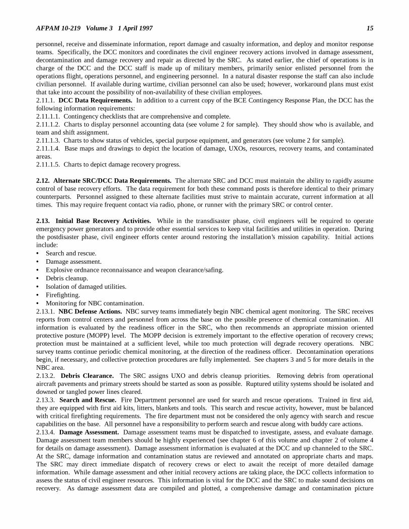
AFPAM 10-219 Volume 3 1 April 1997 15
personnel, receive and disseminate information, report damage and casualty information, and deploy and monitor responseteams. Specifically, the DCC monitors and coordinates the civil engineer recovery actions involved in damage assessment,decontamination and damage recovery and repair as directed by the SRC. As stated earlier, the chief of operations is incharge of the DCC and the DCC staff is made up of military members, primarily senior enlisted personnel from theoperations flight, operations personnel, and engineering personnel. In a natural disaster response the staff can also includecivilian personnel. If available during wartime, civilian personnel can also be used; however, workaround plans must existthat take into account the possibility of non-availability of these civilian employees. 2.11.1. DCC Data Requirements. In addition to a current copy of the BCE Contingency Response Plan, the DCC has thefollowing information requirements: 2.11.1.1. Contingency checklists that are comprehensive and complete. 2.11.1.2. Charts to display personnel accounting data (see volume 2 for sample). They should show who is available, andteam and shift assignment. 2.11.1.3. Charts to show status of vehicles, special purpose equipment, and generators (see volume 2 for sample). 2.11.1.4. Base maps and drawings to depict the location of damage, UXOs, resources, recovery teams, and contaminatedareas. 2.11.1.5. Charts to depict damage recovery progress. 2.12. Alternate SRC/DCC Data Requirements. The alternate SRC and DCC must maintain the ability to rapidly assumecontrol of base recovery efforts. The data requirement for both these command posts is therefore identical to their primarycounterparts. Personnel assigned to these alternate facilities must strive to maintain accurate, current information at alltimes. This may require frequent contact via radio, phone, or runner with the primary SRC or control center. 2.13. Initial Base Recovery Activities. While in the transdisaster phase, civil engineers will be required to operateemergency power generators and to provide other essential services to keep vital facilities and utilities in operation. Duringthe postdisaster phase, civil engineer efforts center around restoring the installation’s mission capability. Initial actionsinclude:• Search and rescue.• Damage assessment.• Explosive ordnance reconnaissance and weapon clearance/safing.• Debris cleanup.• Isolation of damaged utilities.• Firefighting.• Monitoring for NBC contamination. 2.13.1. NBC Defense Actions. NBC survey teams immediately begin NBC chemical agent monitoring. The SRC receivesreports from control centers and personnel from across the base on the possible presence of chemical contamination. Allinformation is evaluated by the readiness officer in the SRC, who then recommends an appropriate mission orientedprotective posture (MOPP) level. The MOPP decision is extremely important to the effective operation of recovery crews;protection must be maintained at a sufficient level, while too much protection will degrade recovery operations. NBCsurvey teams continue periodic chemical monitoring, at the direction of the readiness officer. Decontamination operationsbegin, if necessary, and collective protection procedures are fully implemented. See chapters 3 and 5 for more details in theNBC area. 2.13.2. Debris Clearance. The SRC assigns UXO and debris cleanup priorities. Removing debris from operationalaircraft pavements and primary streets should be started as soon as possible. Ruptured utility systems should be isolated anddowned or tangled power lines cleared. 2.13.3. Search and Rescue. Fire Department personnel are used for search and rescue operations. Trained in first aid,they are equipped with first aid kits, litters, blankets and tools. This search and rescue activity, however, must be balancedwith critical firefighting requirements. The fire department must not be considered the only agency with search and rescuecapabilities on the base. All personnel have a responsibility to perform search and rescue along with buddy care actions. 2.13.4. Damage Assessment. Damage assessment teams must be dispatched to investigate, assess, and evaluate damage.Damage assessment team members should be highly experienced (see chapter 6 of this volume and chapter 2 of volume 4for details on damage assessment). Damage assessment information is evaluated at the DCC and up channeled to the SRC.At the SRC, damage information and contamination status are reviewed and annotated on appropriate charts and maps.The SRC may direct immediate dispatch of recovery crews or elect to await the receipt of more detailed damageinformation. While damage assessment and other initial recovery actions are taking place, the DCC collects information toassess the status of civil engineer resources. This information is vital for the DCC and the SRC to make sound decisions onrecovery. As damage assessment data are compiled and plotted, a comprehensive damage and contamination picture

16 AFPAM 10-219 Volume 3 1 April 1997
emerges permitting development of the recovery strategy. Critical utilities must be reestablished or substituted. Electricalpower to critical operations must be restored and maintained. Critical facilities and utility systems must be restored orrepaired to resume the operational mission. Emergency repairs to eliminate conditions that could cause injury or loss oflife, or to protect government property from further damage, may start without prior approval from higher headquarters.The repair strategy is carried out as defined in volume 4 and chapters 7 and 11 of this volume. 2.14. Command and Control Communications. The BCE is responsible for providing radio net communications betweenthe fire department, the DCC, the SRC and the command post (if the latter two are not collocated). Alternate means ofcommunications must be established and practiced. Runners are a viable alternative to radios, but can be impractical ifgreat distances are involved. If field telephones are available, they should be considered as a viable option. If your radio isinoperative due to power failure, try mobile vehicle radio units. If you cannot use your radio due to suspected enemymonitoring, use other means such as runners or field phones. Does your base have radio "dead zones" or areas of highinterference? Effects of dead zones can be avoided by message relay techniques, changing location, or moving closer to thecontrol center. Sometimes the effects of dead zones are directional, that is, transmissions are picked by other radios not inthe same direction as the control center. BCE personnel using radios should be familiar with the locations of dead zonesand how to minimize their effects. Your installation communications staff officer and the intra-base non-tactical radiopersonnel (radio maintenance shop) can assist in identifying dead zones. Once identified, it is a good idea to annotate theinformation on the control center’s base layout map. Make it a practice to advise all new or infrequent radio users of theselocations and ways to minimize their effects. Another good communications practice to establish in support of baserecovery is maintaining strict control over mobile radio assets. Lost or damaged radios during contingencies or wartime arevirtually impossible to quickly replace. Also pay close attention to recharging batteries. Several dead batteries causingpartial loss of communications when performing recovery activities can severely reduce the efficiency and effectiveness ofrepair and damage assessment crews. Needless to say, this immediately impacts the speed at which base missioncapabilities are reestablished. The key to effective radio communications is to ensure communications assets are fullyserviceable and all personnel exercise radio discipline, use good enunciation and use the "ten code" system (table 2.1). Table 2.1. Radio Call Signs--"Ten-Code" System.
10-1 Reception Poor (cannot understand) 10-12 Readiness Standby 10-2 Reception Good 10-13 Crash Alert Standby (emergency) 10-3 Stop Transmitting 10-14 Arrived at Scene or Position 10-4 Message Received 10-15 Finished With Last Assignment 10-5 Standby (operator busy) 10-16 Disregard Last Assignment 10-6 Station Clear 10-17 Maintain Radio Silence 10-7 Out of Service Until..... or for .....Minutes 10-18 Involved in Accident 10-8 In-Service 10-19 Return (or returning) to Station 10-9 Repeat Last Message 10-20 What Is Your Location 10-10 Return to Normal Operations 10-21 Radio Check 10-11 Flightline Patrol 10-22 Standby - Emergency Transmission, All Units
2.15. Continuity of Command and Control. 2.15.1. Predesignated Personnel. Provision must be made for the continuity of engineer leadership both in the SRC andthe DCC. The establishment of alternate command centers aids in solving part of the problem in terms of facility support.However, the possibility exists that key personnel assigned to serve in either the primary or alternate command centers maybecome casualties and unable to perform their primary duties. Other engineer personnel must be predesignated to fill in forkey personnel casualties. This predesignation must be done in advance of any hostilities and sufficient training andcommand post familiarization provided so that a smooth transition can be obtained if and when required. 2.15.2. Change-Over Briefings. Continuity of command and control also is influenced by round-the-clock shiftoperations. In effect, every time there is a shift change continuity is affected. The degree of professionalism and effort putinto change-over briefings is directly proportional to the degree of command and control continuity maintained. Thesebriefings must be in sufficient depth and scope so as to make the shift replacement conversant on all major recoveryactivities underway and those programmed to start during his or her watch. Fancy eyewash slides are not necessary norworth the time to produce; however, just passing the logbook won’t cut it either. Brief your replacement as you would wishto be briefed yourself. 2.15.3. Recall of Dispersed Personnel/Equipment. Equipment and personnel are dispersed in order to minimizedestruction, damage, and injury. Lines of communication must be maintained with dispersed assets and informationexchanged on the current status of the assets. Dispersed assets that survived the disaster can be recalled to assist in taking

AFPAM 10-219 Volume 3 1 April 1997 17
recovery actions. The commander should consider recalling the assets for recovery actions after assessing the possibility ofa threat recurrence. Only those dispersed assets necessary for sustained operation of critical functions should be recalled. 2.16. Summary. This chapter discussed the concepts for command and control during contingencies. It addressed thebasic relationships between the concepts of command and leadership, and control and management. In a contingencysituation strong leadership, sound knowledge, good strategy and direction, effective communications, and properorganization are essential for success. This chapter then related these features to the chain of command structure used atunit level. The tasks and responsibilities of the wing operations center, survival recovery center, and the damage controlcenter were discussed in detail. Lastly, the duties and responsibilities of key personnel in these control centers wereaddressed. ____________________________________________________________________________________________________
Chapter 3
COMMON ACTIONS AND CONCEPTS
"Every soldier must be brought to the state where it can be said of him: You havelearned all there is to be learned, take care not to forget it." Field Marshal Aleksandr Suvorov 1729 - 1800
3.1. Introduction. There are certain basic contingency response actions and concepts that will affect most, if not all,engineer forces and therefore should be part of any individual’s overall readiness awareness. Some of these actions andconcepts are extensive and are addressed as separate chapters in this document. Others are of a more limited scope arecontained in this chapter. 3.2. Overview. Since this chapter begins the discussion of postdisaster procedures, great emphasis will be placed on thetransition from planning to implementation in all actions of the civil engineer force. Since appropriate resources will becritical for postdisaster efforts, the chapter begins with a description of dispersal measures to ensure needed resources are inprotected locations prior to a catastrophe. Next, shelter radiological monitoring procedures are outlined to improve thesurvival rate of personnel in the event of a nuclear attack. Since chemical and biological agents may be used duringwartime, monitoring measures are described to enhance opportunities for early detection of these toxic substances. Latersections of the chapter will deal with the effective management of available resources. The establishment of personnelaccountability procedures guarantees that manpower is allocated to the most essential functions. Finally, the compositionsand capabilities of the various emergency crews are discussed to ensure that all potential life threatening and propertydamaging situations are rectified. 3.3. Dispersal Actions. 3.3.1. Basic Concepts. Dispersal plans, developed before the disaster or attack, identified dispersal resources, locations,and methods. These plans were based upon the planner’s best estimate of what would be required and available toaccomplish dispersal actions at the time of an emergency. Now that a disaster or attack is imminent, it is time for the BCEto review the dispersal plans and determine how they apply to the current situation. 3.3.1.1. One of the most crucial factors in conducting an effective dispersal operation is time. The greater the warningprior to an emergency, the more attractive dispersal becomes as a resource protection option. Therefore, it is essential thatthe BCE carefully evaluate all warnings regarding potential disasters or enemy actions and make early decisions regardingthe feasibility of dispersal. 3.3.1.2. The BCE’s decision as to whether assets should be dispersed depends upon the perceived impact of the threat andestimates regarding the time available for dispersal. A prudent and judicious process of weighing one risk against the otheris necessary to determine if the benefits of dispersal outweigh the costs. For example, dispersing resources may increaseprotection, but the manpower required to transport those assets may seriously undermine personnel strengths. To furtherillustrate, dispersing personnel and equipment to high ground across a river may protect these assets from the effects of aflood; but if the flood washes out the connecting bridge, these assets are lost to the recovery effort. If the BCE or wingcommander anticipates regrouping at another location following the emergency, this could be a strong motivating factor fordispersing some of those assets during the pre-disaster or attack phase. The best dispersal plan is only effective if it istempered by the conditions existing at the time of an emergency.

18 AFPAM 10-219 Volume 3 1 April 1997
3.3.2. Specific Activities. If, after careful consideration, the civil engineer management team decides that dispersal is avalid option, the following actions should be taken: 3.3.2.1. Marshall dispersal forces and provide them with a comprehensive briefing of actions to be taken. Any changes topreplanned dispersal activities should be emphasized. Especially important are changes in dispersal locations, dispersalassets, and dispersal methods. If dispersing off-base, be sure personnel have current maps with alternate routes back to thebase marked in case primary routes are blocked. 3.3.2.2. Organize dispersal assets and arrange the necessary transportation. This step includes all activities necessary formobilization of dispersal assets; loading trucks with equipment and materials; fueling equipment that will be driven to thedispersal location; organizing convoys for land movements to dispersal sites off-base, arranging airlift support for long-range dispersal; and changing dispersal routes as needed to reflect the current situation. 3.3.2.3. Move resources to dispersal sites. Assembled assets are transported to the dispersal location as expeditiously aspossible. This is especially important to ensure that valuable resources are not exposed, or concentrated in a single location,when the catastrophe strikes. 3.3.2.4. Establish and maintain communications with appropriate command center. Dispersed forces must maintaincontact with the command center. The command center must be advised of any factors which affect the capability of thedispersed forces to accomplish their postdisaster or postattack mission. Remember to provide mobile generator support todispersal sites for powering base station radios, battery chargers, and lighting. Include a means of refueling the generatorsalso--nothing elaborate, portable fuel containers should be sufficient. 3.3.2.5. Protect dispersed assets. It is vital that dispersed resources be secured and protected from the effects of a disasteror enemy actions. Otherwise, the purpose of the original dispersal will be defeated and the force ineffective in respondingwhen recalled. Depending upon the type of emergency, protective measures could range from boarding up windows andsandbagging to construction of standoff revetments. Plan accordingly; if time will not permit accomplishment of protectivemeasures once arriving at a dispersal location, complete the hardening tasks as one of your predisaster preparation actions. 3.4. Radiological Shelter Monitoring. 3.4.1. Introduction to Radiological Monitoring. In the event of a nuclear attack, shelters will be points of survival fromwhich personnel will emerge to carry out recovery and rehabilitation tasks. For this reason, BCEs use a radiologicalexposure control system to ensure the safety of shelter occupants. This section furnishes information concerning monitoringtechniques and procedures, protective measures, and the application of collected data to determine hazards to personnel. 3.4.2. Types of Radiation. To understand the effects of radiation on living tissue, it is helpful to have some backgroundinformation on the characteristics of various types of radiation. The effects of nuclear radiation are described in thefollowing paragraphs. 3.4.2.1 Alpha Particles. Alpha particles are particles of matter which have been ejected from the nucleus of a radioactivematerial and are literally small pieces of matter traveling through space. Alpha particles have the lowest penetrating powerof any nuclear radiation, and can be stopped by 1 inch of air, a sheet of paper, or undamaged human skin. Alpha particlesare only hazardous if ingested, inhaled or absorbed through open wounds (figure 3.1). Figure 3.1. Alpha Radiation.
3.4.2.2. Beta Particles. Beta particles are identical to the high speed electrons of an atom. They are extremely light andtravel at high velocities. Beta particles have a greater penetrating power than alpha particles, but they can still be stoppedby a few feet of air or heavy clothing (figure 3.2). Beta particles can cause tissue damage in humans if fallout is ingested orheavy fallout contamination of the skin is not quickly removed. The primary effect of beta particles will be radiation burnsto exposed skin tissue.
AFPAM 10-219 Volume 3 1 April 1997 19
Figure 3.2. Beta Radiation.
3.4.2.3 Gamma Rays. Gamma rays are a type of electromagnetic radiation which travels at the speed of light. Gammarays are similar to X-rays used in the medical field and are highly lethal. The basic difference between X-rays and gammarays is their source. Gamma rays originate in the nucleus of the atom, while X-rays are formed in the path of electronsabout the nucleus. Gamma rays have an extremely high penetrating ability. It requires several feet of earth or at least one-inch of lead to reduce the penetrating powers of gamma rays (figure 3.3). Figure 3.3. Gamma Radiation.
3.4.2.4. Nuclear Radiation Injury. The harmful effects of nuclear radiation are caused by the ionization produced in thecells composing living tissue. As a result of the ionization, some of the components essential to the normal functioning ofthe cells are altered or destroyed. All radiation is capable of producing ionization directly or indirectly. Alpha and betaparticles, X-rays, and gamma rays cause radiation injury of the same general type. Since gamma rays have the greatestpenetrating ability, they are the ones that the shelter monitor is most concerned with when determining hazards topersonnel. 3.4.3. Principles of Fallout Protection. Three basic methods are used to minimize exposure to ionizing radiation: time,distance, and some type of shield. Protection is provided by controlling the length of exposure time, the distance betweenthe body and the source of radiation, and placing an absorbing material between the body and the source of radiation. Thetime factor is always involved and will normally be used in combination with distance, shielding, or both. For a betterunderstanding of the three methods of protection, they will be discussed separately. 3.4.3.1. Time. When considering the principle of time, it is important to look at it from two angles--radioactive decay andindividual exposure time. 3.4.3.1.1. We have no control over radioactive decay. The decay rate is determined by the half-life of the radioactiveelements that make up the fallout. Half-life is the time required for a given radioactive element to lose half of its originalradioactivity. Since fallout is composed of a combination of many radioactive isotopes with half-lives ranging from afraction of a second to billions of years, it is difficult to calculate the exact decay rate. However, experiments haveestablished the "7-10" rule which states that for each sevenfold increase in time, beginning with the hour which all fallout ison the ground and the dose rate begins to fall, there is a tenfold decrease in the intensity of radioactivity (see table 3.1). Thecentigray (cGy) is used to measure exposure to gamma and X-rays. Since this decay is constantly reducing the levels ofradioactivity following a nuclear detonation, the longer outside activities can be delayed, the less the radiation danger topersonnel.

20 AFPAM 10-219 Volume 3 1 April 1997
Table 3.1. Times vs. Dose Rate.
TIMES VS. DOSE RATE
TIME AFTER DETONATION
DOSE RATE
1 hour 1,000 cGy/hr. 7 hours - (7) (1 hr.) 100 cGy/hr. 49 hours (2 days) - (7)(7 hr.) 10 cGy/hr. 343 hours (2 weeks) - (7)(49 hr.) 1 cGy/hr.
3.4.3.1.2. While the decay of radioactive materials cannot be controlled, you do have control over exposure time. In theearly periods following an attack, when radiation levels are very high, exposure should be kept to an absolute minimum.No task should be conducted outside of the protection of the shelter unless it is absolutely necessary. Even after radiationlevels have decreased, exposure should be carefully monitored and rotated among the occupants of the shelter to ensure noindividual receives an excessive amount. You should maintain an accurate record of daily radiation exposure andaccumulated radiation dosage to that date. More detailed information is provided in this section’s paragraph on radiationexposure guidance. 3.4.3.2. Distance. The simplest way to explain the distance factor in radiation protection is to say that the farther you arefrom the source of radiation, the safer you are. This distance factor can be very important in determining the protectionfactor of various areas when large buildings are used as shelters. In figure 3.4 the walls and roof of the building showncreate distance (D) between the person inside the building and the contamination (fallout) outside. Individual A, in thecenter of the first floor, is farther from the radiation source than individuals B and C. Thus individual A will receive lessradioactive exposure. Figure 3.4. Distance as a Protective Factor.
3.4.3.3. Shielding. The amount and type of shielding are very important in determining the overall protection factor of theshelter. Since alpha and beta particles are stopped by thin protective barriers, the main concern in selection of sheltershielding material will be the reduction of gamma ray penetration. The efficiency of a given substance in stopping gammarays is determined by its density. The denser the material, the more effective it is in preventing penetration. Figure 3.5shows the thickness of various shielding materials required to stop the same amount of gamma radiation. Selection of theappropriate shielding substance will be based on the application intended and the availability of materials. For example, ina situation where space is critical, lead would be an excellent choice since its high density allows effective shielding withminimum thickness. In situations where space is not a consideration, but cost is important, a less dense, lower cost materiallike earth or concrete might be a better choice.

AFPAM 10-219 Volume 3 1 April 1997 21
Figure 3.5. Relative Shielding Efficiency of Various Materials.
3.4.3.4. Protection Factor. The principles of fallout protection described in the preceding paragraphs have a significantimpact on determining the protection factor of a shelter. The protection factor may be defined as the relative reduction inthe amount of radiation received by a person in a protective location, compared to the amount received if unprotected. Toillustrate, if a shelter has a protection factor of 100, an unprotected person would be exposed to 100 times more radiationthan someone inside the shelter. Knowing the protective factor of the shelter is essential if the shelter monitor is tocalculate outside radiation levels based on interior readings. 3.4.4. Radiological Monitoring Instruments. Shelter monitors must have the proper tools. Many instruments areavailable, but they all fall into two general classes: survey meters and dosimeters. These instruments are designed to detectand measure gamma radiation. Some are capable of detecting alpha and beta radiation. For fallout, you are primarilyconcerned with gamma radiation. To better understand the use of radiological monitoring instruments, contact personnelassigned to your readiness flight. 3.5. Nuclear Accident Response. 3.5.1. General Activities. Many of the techniques and procedures associated with shelter monitoring have a parallel innuclear accident situations. A nuclear accident may involve damage to a nuclear weapon but not detonation; therefore,fallout would not be present. The potential for the release of radioactive particles is present, however. Engineer personnelcould find themselves involved in several activities associated with a nuclear accident condition. For example, firefightersmight have to extinguish fires around the accident site. Other engineers might have to isolate utility systems and movematerials and equipment from the area. The need to accomplish facility repair might also arise. Lastly, there is a greatprobability that engineers will be involved in immediate and long term site restoration efforts. Any of these taskings couldlead to exposure to radiation and you must be in a position to monitor and control these activities. 3.5.2. Initial Response Force. In the event of a nuclear accident the nearest military installation will respond to the sitewith an initial response force (IRF). The IRF performs emergency operations to save lives, provide security, confirm ordeny the presence of contamination, and contain the hazard as much as possible. The engineer readiness component of theIRF conducts the radiation monitoring activities. 3.5.3. Monitoring Contamination. While the threat of severe radiation injury is probably low at the site of a nuclearaccident, cumulative dose quantities should be monitored closely, particularly for those personnel who may be required toconduct long term cleanup and restoration actions. Work closely with your readiness counterparts to see this isaccomplished. Also, do not forget to watch for possible contamination of vehicles and equipment at the accident site.Decontamination actions are required before the equipment can be removed from the cordoned area. 3.6. Chemical and Biological Monitoring. 3.6.1. General Information. The uncertainty of what warfare techniques may be encountered in future wars makes itnecessary that civil engineer forces be prepared to operate in many hazardous environments. Chemical and biologicalenvironments are two of the most dangerous conditions that civil engineer forces could face during a wartime contingency.Chemical agents can be introduced to the air base environment by the use of bomblets, artillery shells, missiles, sprays,aerosols, and through the base water supply. Biological agents are employed through aerosols, insect vectors (infectedinsect), and the water supply (figure 3.6). Since many of these employments will involve covert measures which are not asimmediately obvious as is a conventional attack, increased vigilance and accurate detectors are needed to provide adequatewarning. Figure 3.6. Dispensing Chemical and Biological Agents.
3.6.2. Chemical and Biological Environments. 3.6.2.1. Chemical Environment. The chemical environment will be characterized by solid, liquid, aerosol, or gaseouschemical agents which pervade an area causing widespread incapacitation or death of personnel. Since the types ofchemical agents present may be nerve, blood, blister, or choking agents, monitoring methods will have to be geared to

22 AFPAM 10-219 Volume 3 1 April 1997
detect a range of substances. The characteristics and disabling effects of the various chemical agents are detailed in chapter5, Chemical Defense Activities. The most important factor to remember for chemical monitoring activities is the need forearly and accurate detection of any chemical warfare agent to ensure that personnel have time to take adequate protectionmeasures. 3.6.2.2. Biological Environment. Biological agents are used by an enemy to produce disease which reduces the ability ofthe opponent to continue combat operations. Potential anti-personnel biological agents consist of living microorganismssuch as fungi, bacteria, and viruses. These pathogens affect the body much like common diseases such as typhoid orinfluenza. The effects of these agents can range from minor incapacitation (common cold) to prolonged illness that resultsin death (plague). Since biological agents are easily transmitted to other personnel, this dreadful weapon has the potentialfor covering larger areas than many other forms of warfare. Although there are no verified instances of the use of biologicalweapons in modern warfare, these pathogens could be produced, stockpiled, and disseminated without being immediatelydetected. Poor sanitary conditions prevalent during wartime compound biological warfare detection problems. 3.6.3. Monitoring for Chemical Agents. Effective monitoring for the presence of chemical agents involves the use ofappropriate detection equipment in a manner that provides the best opportunity for early detection of any chemical agentsintroduced into the area. The following paragraphs describe current chemical detection equipment and recommendedmonitoring procedures. 3.6.3.1. Detection Equipment. The most common chemical detection devices available for use by USAF personnel are: 3.6.3.1.1 M8 Chemical Agent Detector Paper. The M8 chemical agent detector paper (figure 3.7) provides a singlemethod for testing for the presence of liquid nerve or blister agents.• Description. This detection item consists of twenty-five 4 x 2-1/2 inch sheets of dye-impregnated paper bound in
booklet form and perforated for easy removal. The sheets turn dark green, yellow, or red when contacted by liquidforms of V or G type nerve agents or mustard agents respectively. A color chart on the inside cover of each bookletprovides a direct method of comparison for agent identification.
• Function. The M8 paper is used to detect nerve and blister chemical agents in liquid form. The paper must directlytouch the liquid for a good test. It is best suited for use on non-porous materials since its reliability is reduced when theagent is absorbed. Since some solvents can cause the paper to change color, it is unreliable for determining thecompleteness of decontamination.
Figure 3.7. M8 Chemical Agent Detector Paper.
3.6.3.1.2. M9 Chemical Agent Detector Paper. The M9 chemical agent detection paper (figure 3.8), with its adhesivebacking, provides greater employment flexibility than the M8 paper.• Description. The M9 detector paper is supplied in a roll 2 inches wide by 15 feet in length. The roll is in a dispenser,
which is supplied with a resealable plastic bag, and packed in a moisture vapor barrier bag. The paper has an adhesivebacking allowing it to be attached to clean, dry surfaces. The paper is green and contains detector dye suspended in apulp matrix. When contacted by liquid chemical agent, the detector produces a contrasting color change to pink, red, orpurple.
• Function. The M9 detector paper is used to indicate the presence of liquid nerve/blister agents. It must come into directcontact with the liquid agent to ensure a reliable test. The paper may be worn around the wrist, arm, and/or ankles forcontinuous monitoring or it may be exposed on a surface for visual warning/monitoring.

AFPAM 10-219 Volume 3 1 April 1997 23
Figure 3.8. M9 Chemical Agent Detector Paper.
3.6.3.1.3. M256 Chemical Agent Detector Kit. The M256 chemical agent detector kit (figure 3.9) is an integrated kitthat will detect the presence of chemical agents in liquid or vapor form.• Description. The M256 kit consists of twelve individually packaged sampler/detectors, instruction cards, and a packet
of M8 chemical agent detector paper. The components are packaged in a small plastic case with each of the twelvesampler/ detectors containing test spots and required reagents prepackaged in finger-crushable ampoules. Thesampler/detector responds with a marked color change upon contact with chemical agents of concentrations at or abovethose reducing the efficiency of an unmasked individual.
• Function. The M256 kit provides a portable capability for detecting field concentrations of nerve, blister, or bloodagents; to differentiate between classes of agents; and to determine when it is safe to unmask following a chemicalattack. The sampler/detector will detect harmful vapor concentrations of nerve, blister, and blood agents in a singleexposure. The M8 paper is used to detect liquid nerve and blister agents.
Figure 3.9. M256 Chemical Agent Detector Kit.

24 AFPAM 10-219 Volume 3 1 April 1997
3.6.3.1.4. M8A1 Automatic Chemical Agent Alarm System. The M8A1 system (figure 3.10) is used to detect thepresence of nerve gas and sound an alarm.• Description. The M8A1 system consists of several components: the M43A1 detector, M42 alarm units, a power
supply, and mounting hardware. A detection cell inside the M43A1 component senses the presence of nerve agents inthe air and triggers an electronic module, which, in turn, activates the M42 warning horn. The system can be poweredby battery or by 110/220v sources.
• Function. The M8A1 system provides a portable method for detecting field concentrations of nerve gas. It can be usedat a fixed location, carried in a backpack, or mounted on a vehicle. It is all-weather capable and fully functional underdusty conditions. Additionally, several alarms can be connected to a single M43A1 detector.
Figure 3.10. M8A1 System Components.
3.6.3.1.5. Automatic Liquid Agent Detection System (ALAD). The ALAD system is used to detect the presence of liquidnerve and blister agents and sound an alarm.• Description. The ALAD is a portable, battery-powered unit consisting of a 4-inch detector grid, alarm horn and light
and interface terminals. The interface terminals allow the ALAD to be connected to a remotely located alarm systemand a central alarm console.
• Function. ALADs are used in overseas, high threat areas to warn personnel that a liquid chemical attack has occurred,integrate with other detectors to verify alarms, and identify areas of the base which are contaminated by liquid agents.
3.6.3.1.6. M-90 Automatic Vapor Agent Detector (AVAD). The AVAD is a commercially available point chemicaldetector which will replace the M8A1 system.• Description. The AVAD is a lightweight, easily transportable, battery-powered detector with an alarm capability.• Function. AVADs are capable of detecting all known nerve and blister agent vapors in a stand-alone configuration. 3.6.3.2. Limitations of Current Chemical Detection Equipment. Most of the chemical detection equipment in use todayconsists of "off-the-shelf" items acquired in the mid-1970s as a result of the increased concern with Soviet chemical warfarecapabilities. This equipment has limitations which must be compensated for if it is to provide an adequate monitoringsystem during future chemical attacks. The primary limitations of most of the existing detection equipment are: 3.6.3.2.1. Remote Detection. The characteristics of current USAF detection equipment precludes monitoring for chemicalagents from significant distances. 3.6.3.2.2. Discrimination. Although current equipment is designed to detect numerous types of toxic chemical agents, it isnot effective in quickly differentiating between specific agents. 3.6.3.2.3. Quantification. The concentration of a chemical agent is important in determining its effect on personnel.Current USAF chemical detectors only indicate the presence of a toxic agent; none of the devices measure the concentrationof the substance. 3.6.3.2.4. Agents on Surfaces. The unreliability of current measures in detecting chemical agents on certain types ofsurfaces makes them unsuitable for many applications. An improved surface detection system would be especially usefulduring decontamination efforts. 3.6.3.2.5. No Integration Features. Most current detection systems operate independently and have no provisions forinterface with other elements of the base survivability and recovery system. 3.6.4. Chemical Monitoring Procedures. Now that the characteristics and limitations of currently available chemicalagent detection equipment have been discussed, procedures must be developed to ensure that these devices are employed inthe most effective manner. The procedures outlined in this section should be considered as general guidance. Localenvironmental conditions and intelligence estimates of probable enemy actions during an attack will dictate specificchemical monitoring procedures. The primary concerns of chemical monitoring are in providing initial chemical attackwarning, postattack all-clear indications, decontamination management assistance, and contamination avoidance assistance. 3.6.4.1. Initial Chemical Attack Warning. 3.6.4.1.1. When intelligence reports or enemy actions indicate that a chemical attack is probable, chemical agent alarmsshould be activated. If a detector indicates the presence of a toxic substance, a warning must be passed immediately to themain force area. This advance warning will enable the main force to increase their protection level before the arrival of thechemical agent. 3.6.4.1.2. The positioning of the detectors will depend on the availability of detection equipment, environmentalconditions, and the perceived hostile threat. Detectors are positioned upwind of the base and near key areas. If the winddirection shifts substantially, the detectors may have to be repositioned. Readiness personnel are responsible for deploying

AFPAM 10-219 Volume 3 1 April 1997 25
and redeploying detectors. 3.6.4.2. Monitoring for Postattack All-Clear Indication. Since personnel can accomplish their assigned tasks easierwithout the protective chemical ensemble, monitoring for the continued presence of chemicals following an attack isimportant. The M256 kit is normally used to determine when it is safe to unmask. To determine if liquid contaminationremains, M8 or M9 detection paper can be used. More detailed instructions on chemical monitoring prior to unmasking areprovided in chapter 5, Chemical Defense Activities. 3.6.4.3. Monitoring in Decontamination Operations. Effective chemical monitoring is essential during decontaminationoperations to ensure that toxic chemicals have been eliminated or reduced to non-toxic levels. The M256 chemical agentdetector kit is used to check equipment and other surfaces following decontamination. The M8 and M9 detector paper canalso be used for this purpose, but if solvents were used during the decontamination process, the M8 detector paper couldgive an erroneous indication. If personnel are careful in removing contaminated protective gear, decontamination is notnormally required. Contaminated equipment remains in a holding area until needed for reuse, disposal, or more extensivedecontamination. 3.6.4.4. Contamination Avoidance. 3.6.4.4.1. Even after a chemical attack has been launched, casualties can be reduced through proper use of protective gearand by avoiding areas of liquid chemical agent. Good chemical monitoring procedures can be invaluable in detection ofthese chemical "hot spots." Depending upon the type of toxic agent involved, any of the previously discussed detectionequipment might be used to avoid contaminated areas. As mentioned earlier, M9 detection paper can be worn around anindividual’s wrist, arm, and/or ankle as a continuous monitor to warn of areas of contamination. The M256 detector kit canbe used to sample for suspected contamination prior to entering an area. Finally, for suspected nerve agent vapor, theautomatic chemical agent alarm set or the AVAD can be moved into an area ahead of the work force to detectcontamination. CAUTION: Chemical contamination ingested into air filters, ducts and other components of collectiveprotection shelters continues to pose a danger to personnel after the general area has been declared free of contamination.Coordinate chemical monitoring support and guidance for this type of situation with the readiness staff. 3.6.4.4.2. Care should be taken to avoid contamination from unexpected sources. For example, discarded contaminatedclothing, chemical detector equipment, air filters, and similar items are potential sources of recontamination if not disposedof properly. The most common methods of disposition are burning or burying. Burning of some chemical agents canproduce hazardous vapors. Get advice from the readiness staff. Civil engineers should be prepared to establish excavationsat various air base locations for disposal of these dangerous materials. Care should be taken to locate these excavations toprevent hazards to the general base population. Also, exact locations and a listing of the general contents of burial sitesmust be recorded. 3.6.4.5. A Final Consideration. The value of any chemical detection system lies in its ability to detect a toxic agent andwarn friendly forces in sufficient time for them to assume a protective posture. This quick detection capability is challengedby the inherent limitations of current detection systems and such factors as the fact that some potential air bases with USAFpresence could be only a few flight minutes from hostile air bases. If these limitations are to be overcome in future chemicalconfrontations, each member of the civil engineer work force must understand the limitations of available detection devicesand be prepared to compensate for reduced warning by increased readiness and immediate protective action. 3.6.5. Monitoring for Biological Agents. 3.6.5.1. Monitoring for biological warfare agents is more difficult than chemical agent monitoring because there are noavailable detectors to provide an immediate warning when pathogens are present. Therefore, biological monitoring consistsof close observations of personnel for unexplained illnesses, periodic sampling of water supplies for biologicalcontamination, and active reconnaissance operations for sampling following suspicious enemy activities. For example, aspray released by an enemy aircraft which did not activate chemical agent detectors might lead to suspicions of a biologicalagent release. Under these conditions an active sampling mission is conducted, normally by bioenvironmental engineers.The samples are forwarded to the nearest medical laboratory facility to determine if hazardous pathogens are present. 3.6.5.2. If biological agents are discovered, the civil engineer force may have to take action to prevent degradation of theair base’s operational capability by the pathogen. The location and type of biological contamination will dictate controlactions. Contamination in the water supply may be controlled by increasing the chlorine level or requiring all consumers toboil water prior to use. Biological contamination associated with insect or animal populations in the area may be reducedby increased pest control. 3.6.5.3. Since current biological monitoring capabilities do not provide immediate warning of a biological attack, one ofthe most important preventative measures that civil engineers can take is to ensure that sanitation measures are maintainedto the highest possible degree. The reduced sanitation levels common to a wartime environment can contribute to thespread of a biological agent and mask initial detection efforts. 3.6.6. Current Research and Development Efforts. The limited capabilities of the "off-the-shelf" chemical detectionequipment acquired during the 1970s spawned research efforts to develop improved systems. Current research is directed in

26 AFPAM 10-219 Volume 3 1 April 1997
two primary areas: (1) improved chemical and biological detection systems of the point and remote (area) type and (2) anintegrated air base detection and warning system which interfaces with other elements of the base survivability and recoverysystem. Since some of the systems will be issued for field use during the late 1990s/early 2000s, it is appropriate to includea discussion of current research developments. 3.6.6.1. Biological Integrated Detection System (BIDS). The BIDS is a lightweight shelter equipped with a biologicaldetection suite mounted on a HMMMV vehicle. The system is meant to be used for detection of large area aerosol attacksof such biological agents as anthrax, plague and botulinum. BIDS will also collect biological samples and contain anorganic communications capability. 3.6.6.2. Individual Vapor Detector (IVD). The IVD will be a small, low cost device that will rapidly detect chemicalagent vapors and indicate their presence with a visual and audible alarm. The device will be worn by personnel and provideeach person with an individual means of chemical agent detection and warning. 3.6.6.3. Laser Standoff Chemical Detector (LSCD). The LSCD will be a lightweight, vehicle-transportable,contamination monitoring system which can detect and quantify all types of chemical agent contamination, including agentrain, vapors, aerosols, and ground contamination, in a stand-off mode. It will be able to be used in both fixed sites andvehicles and have a detection range of up to three kilometers. 3.6.6.4. Short Range Biological Stand-Off Detection System (BSDS). The BSDS will be a stand alone or ground vehicleor aircraft mounted short to medium range stand-off biological aerosol detector. It will have a detection range, initially, ofup to one kilometer with a five kilometer range being a longer term goal. 3.7. Personnel Accountability. 3.7.1. It is doubtful that the full complement of civil engineer personnel will be available in the aftermath of any majordisaster. Individuals will be on leave, TDY, hospitalized, or unable to reach the base. The recovery effort cannot wait untilthese persons return; it will have to proceed with available manpower. For this reason, an accurate accounting of personnelpresent for duty is essential so civil engineer management can make assignments to vital base recovery functions. 3.7.2. Several options to account for personnel during a contingency exist. Personnel may be instructed to report to acentral assembly point to sign in, or to report to their work section and sign in. Regardless of the method employed,assembly instructions should be in complete detail, including who reports where, when, to whom, and with what equipment. 3.7.3. The following scenario provides an example of typical personnel accountability actions following an emergency. 3.7.3.1. At the time a recall is initiated, on-duty individuals are sent to unlock assembly locations and provide sign inmaterials as required. 3.7.3.2. Incoming personnel report to their assigned assembly area and sign in by air force specialty (AFS). The sign-inprocedures may be accomplished in a number of ways: sign-in sheets for each AFS, or a vertical plotting board withsections for the various AFSs. 3.7.3.3. At a time designated by disaster plans, and indicated on recall checklists, personnel strengths are reported fromassembly locations to the damage control center (DCC). This report should include the following information:• Number of personnel assigned.• Number of personnel on leave.• Number of personnel TDY.• Number of personnel hospitalized.• Number of personnel present for duty.3.7.3.4. The DCC compares this information to the unit manning document, verifies information as necessary through theunit orderly room, and forwards necessary data to the survival recovery center.3.7.4. Personnel accountability procedures will vary from base to base. Therefore, it is most important that you adhere tolocally established procedures and provide an accurate count of personnel present for duty to those responsible for makingbase recovery decisions.
3.8. Emergency Teams.3.8.1. General Information. If the impact of any catastrophe is to be minimized, it is essential that civil engineerpersonnel transition immediately to a contingency mode of operation. Civil engineer emergency teams are the forces whichwill quickly react to keep the base operational during the transdisaster or attack period, reduce the loss of life, preventproperty damage, and begin immediate damage identification and repairs following an emergency. Individuals selected forpositions on these teams must be highly skilled in their specialty and possess the maturity, level-headedness, and physicalstamina to operate effectively in the chaotic and demanding environment that accompanies all catastrophes. Theavailability of qualified personnel at the time of a disaster or attack will be a prime determining factor in how theemergency teams are structured.3.8.2. CONUS Emergency Teams. See chapter 5 of volume 1 of this publication series for guidance on establishingCONUS emergency teams. Due to the varying sizes and compositions of CONUS engineer organizations, numbers of

AFPAM 10-219 Volume 3 1 April 1997 27
emergency teams for each base can vary in quantity. It is incumbent on each BCE to evaluate assigned personnel strengthsand build the needed response teams. The response teams may be filled by military, civilian, or a combination of theseforces.3.8.3. Theater Emergency Teams.3.8.3.1. By the nature of their location, theater emergency teams have a greater likelihood of facing an attack situation thando their CONUS counterparts. Natural disasters cannot be ruled out, however. At an overseas installation having apeacetime USAF engineer presence, theater emergency crews for natural disaster response will be based on standardmanning document authorizations, at least for the initial stages of response. As with the CONUS emergency teams, thepositions may be filled by military personnel, civilian employees, or a combined force. They could be augmented forpostdisaster activities if damages exceeded in-house capability to any great extent. For overseas locations with no in-placeUSAF engineer force, deployed Prime BEEF units would form the emergency response teams. Team composition foroverseas natural disaster response would be similar to that setup for the CONUS response addressed previously.3.8.3.2. In an attack situation, Prime BEEF forces should be in-place prior to commencement of hostilities thereby formingan integral part of the theater emergency response force either by augmenting in-place forces or performing as anindependent unit. The following teams are typical of those to be formed in response to an air base attack situation. Theyare based on the anticipated availability of one 132-person Prime BEEF lead team, two 61-person Prime BEEF followteams, one 6-person EOD lead team, two 4-person EOD follow teams, one 2-person EOD management team, three 2-personEOD high threat augmentation teams, and six 2-person disaster preparedness high threat augmentation teams.3.8.3.2.1. Survival Recovery Center. SRC engineer personnel provide the command and control link between theengineer squadron and the wing command staff. They are instrumental in preparing the recovery response strategy,selecting the MOS, and overseeing the base’s NBC defense posture.
Number ofPersonnel AFS
2 32E32 3E9X11 3E5711 3E8X1
Total 63.8.3.2.2. Damage Control Center. The DCC serves as the focal point for engineer emergency response actions. It directsengineer recovery efforts, coordinates with other base organizations, and links the wing command staff with on-sceneengineer teams.
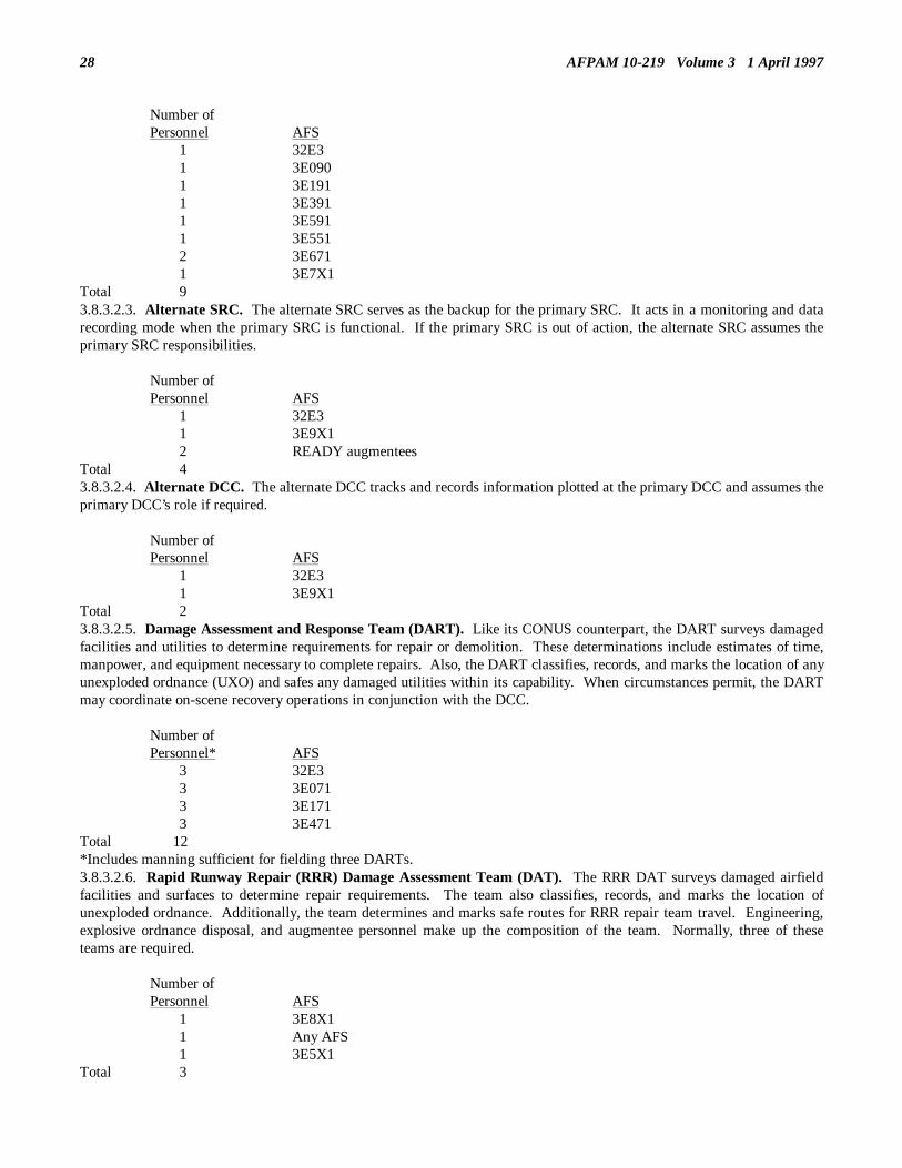
28 AFPAM 10-219 Volume 3 1 April 1997
Number ofPersonnel AFS
1 32E31 3E0901 3E1911 3E3911 3E5911 3E5512 3E6711 3E7X1
Total 93.8.3.2.3. Alternate SRC. The alternate SRC serves as the backup for the primary SRC. It acts in a monitoring and datarecording mode when the primary SRC is functional. If the primary SRC is out of action, the alternate SRC assumes theprimary SRC responsibilities.
Number ofPersonnel AFS
1 32E31 3E9X12 READY augmentees
Total 43.8.3.2.4. Alternate DCC. The alternate DCC tracks and records information plotted at the primary DCC and assumes theprimary DCC’s role if required.
Number ofPersonnel AFS
1 32E31 3E9X1
Total 23.8.3.2.5. Damage Assessment and Response Team (DART). Like its CONUS counterpart, the DART surveys damagedfacilities and utilities to determine requirements for repair or demolition. These determinations include estimates of time,manpower, and equipment necessary to complete repairs. Also, the DART classifies, records, and marks the location of anyunexploded ordnance (UXO) and safes any damaged utilities within its capability. When circumstances permit, the DARTmay coordinate on-scene recovery operations in conjunction with the DCC.
Number ofPersonnel* AFS
3 32E33 3E0713 3E1713 3E471
Total 12*Includes manning sufficient for fielding three DARTs.3.8.3.2.6. Rapid Runway Repair (RRR) Damage Assessment Team (DAT). The RRR DAT surveys damaged airfieldfacilities and surfaces to determine repair requirements. The team also classifies, records, and marks the location ofunexploded ordnance. Additionally, the team determines and marks safe routes for RRR repair team travel. Engineering,explosive ordnance disposal, and augmentee personnel make up the composition of the team. Normally, three of theseteams are required.
Number ofPersonnel AFS
1 3E8X11 Any AFS1 3E5X1
Total 3

AFPAM 10-219 Volume 3 1 April 1997 29
3.8.3.2.7. Rapid Runway Repair Team. This team performs RRR operations to include crater repair, spall repair andMOS marking. RRR command and control capability is also included. Sufficient manpower exists to field six crater repaircrews.
Number ofPersonnel AFS
2 32E3 1 3E000 6 3E032 1 2S071 3 2S051 8 3E031 9 3E151 5 3E131 1 3E291 5 3E27112 3E251 7 3E231 1 3E37111 3E351 9 3E33111 3E45110 3E431 1 3E473 3 3E453 1 3E571 1 3E551 2 3E531 2 3E631 1 8F000
Total 113
3.8.3.2.8. Structural Repair Teams. These personnel are responsible for rescue assistance, wrecking, shoring, repair andrestoration of damaged facilities, mechanical and POL system isolation, debris clearing, and construction of temporaryfacilities. The numbers of teams formed and their configuration is a local decision based on installation characteristics.
Number ofPersonnel AFS
3 3E1712 3E1514 3E3711 3E3511 3E4722 3E4521 3E432
Total 14
3.8.3.2.9. Utilities Repair Teams. These personnel are responsible for isolation, restoration, or expedient re-establishmentof essential utilities to critical base facilities. This includes electrical, water, and waste systems. Number of teams formedand their configuration is a local decision.

30 AFPAM 10-219 Volume 3 1 April 1997
Number ofPersonnel AFS
8 3E0517 3E0521 3E4902 3E4714 3E451
Total 22
3.8.3.2.10. Fire Department. The fire department is responsible for minimizing the loss of life and property as well aspreventing damage which seriously degrades mission capability. Like their CONUS counterpart, the theater fire departmentconcentrates on fire suppression and rescue operations.
Number ofPersonnel AFS
1 3E791/70046 3E7X1
Total 47*
* One additional firefighter serves in the DCC.3.8.3.2.11. Nuclear/Biological/Chemical (NBC) Reconnaissance Teams. These teams monitor for NBC contaminationafter an attack and report results to the SRC. They help identify areas of liquid contamination so contaminationavoidance/decontamination procedures may be implemented.
Number ofPersonnel* AFS
2 3E9X1Total 2
*Augmentees can be used to support these teams if there is a shortage of readiness personnel. The number of teams fieldedis a local decision.3.8.3.2.12. EOD Teams. These teams neutralize, safe or dearm UXO found during damage assessment and base recoveryactivities. Two augmentees are normally assigned to assist. Plan on fielding about three to four of these teams during baserecovery operations.
Number ofPersonnel AFS
2 3E8X12 Any AFS
Total 4
3.8.3.2.13. Bomb Removal Teams. These teams move "safed" munitions to locations where unexpected detonations wouldhave no impact on recovery operations. The augmentees on the teams must be capable of operating dump trucks and frontend loaders/forklifts. If sufficient augmentees are available, consider fielding additional bomb removal teams with oneEOD person activity as overall supervisor.
Number ofPersonnel AFS
1 3E8X12 Any AFS
Total 3
3.8.3.2.14. Generator Response Team. Using generator sets, this team restores power or reestablishes backup power tocritical base facilities. It provides emergency lighting support to RRR teams and other recovery crews. It also ensuresbackup generators are refueled when necessary.

AFPAM 10-219 Volume 3 1 April 1997 31
Number ofPersonnel AFS
1 3E0511 3E0721 3E0521 3E452
Total 4
3.8.3.2.15. Emergency Airfield Lighting System (EALS) Team. This team is responsible for installing the EALS as partof the RRR and base recovery process.
Number ofPersonnel AFS
1 3E0712 3E0511 3E031
Total 4
3.8.3.2.16. Mobile Aircraft Arresting System (MAAS) Installation Team. This team is responsible for installing andmaintaining the MAAS as part of the RRR recovery process.
Number ofPersonnel AFS
2 3E0724 3E052
Total 64.7. 3.9. Summary. This chapter addressed several topics and concepts that pertain to all engineer personnel regardless ofAFS. Dispersal measures, while commonly used to safeguard equipment and materials during contingencies and naturaldisaster situations, require advance planning and case-by-case consideration for each dispersal activation. Dispersal sitesshould be established at locations having access to proper communications, multiple access routes, electrical and refuelingcapabilities, and appropriate protective features. The chapter went on to discuss the basics of NBC operations to includeprinciples of fallout protection and chemical and biological monitoring. Considerable emphasis was placed on the variousdetection systems currently in use or to be fielded shortly. Lastly, examples of various recovery and response teams wereintroduced to provide an indication of how personnel could be organized in times of disaster or war.

32 AFPAM 10-219 Volume 3 1 April 1997
____________________________________________________________________________________________________
Chapter 4
EXPLOSIVE ORDNANCE RECONNAISSANCE
4.1. Introduction4.1.1 Historically, the existence of unexploded ordnance (UXO) (figure 4.1) after an attack has been a frequent occurrence inmodern warfare. Encountering such ordnance was commonplace in London during the blitz of 1940-41 and in many Germancities during the allied strategic bombing campaign of World War II. Much more recently we have all heard of the thousandsof mines and aerial delivered area denial weapons used during the 1991 Iraq war. Although these weapons are designed notto detonate until disturbed, they are still classed as unexploded ordnance. Because of their effectiveness, we can be sure thatsuch weapons will be used again in future conflicts. Whether ordnance remains undetonated due to design or malfunction isnot particularly important to us from a base recovery aspect--what is important is that such ordnance could cause injury,death, or monumental delays in recovery activities and thus interfere with mission accomplishment.
Figure 4.1. Unexploded Ordnance.
4.1.2. During an air base attack, the "smart" enemy will not only use conventional munitions which detonate on impact, butalso "salt" the air base with delay-fused munitions, scatterable mines, and numerous other anti-personnel/material devices.Such actions will drastically hinder aircraft launch and recovery efforts by blocking rapid access of surviving aircraft tousable aircraft pavements, impeding the movement of recovery crews to their equipment and materials, interfering with theresponse of repair and rescue crews to damage sites, and instilling fear and hesitation into all base personnel due to theinherent danger of random or inadvertent munitions detonations. Rapid and accurate explosive ordnance reconnaissance(EOR) becomes critical under such situations so that explosive ordnance disposal (EOD) personnel can prioritize their effortsand can determine areas of the installation that may be relatively safe to traverse. Being that civil engineer recovery tasksrequire access to virtually all areas of the base, our forces must be capable of identifying, reporting, and marking UXOproperly so that we can quickly make our way to the job site and also ensure our EOD personnel respond to the highestpriority needs first.
4.2. Overview. This chapter serves as a guide to all non-EOD civil engineer personnel pertaining to their actions withrespect to unexploded ordnance. It will discuss the more common types of ordnance that may be expected, evidence usuallyseen if unexploded munitions are present, and the engineer’s role in explosive ordnance reconnaissance. To a lesser extent,the chapter will also address the clearance of UXO.
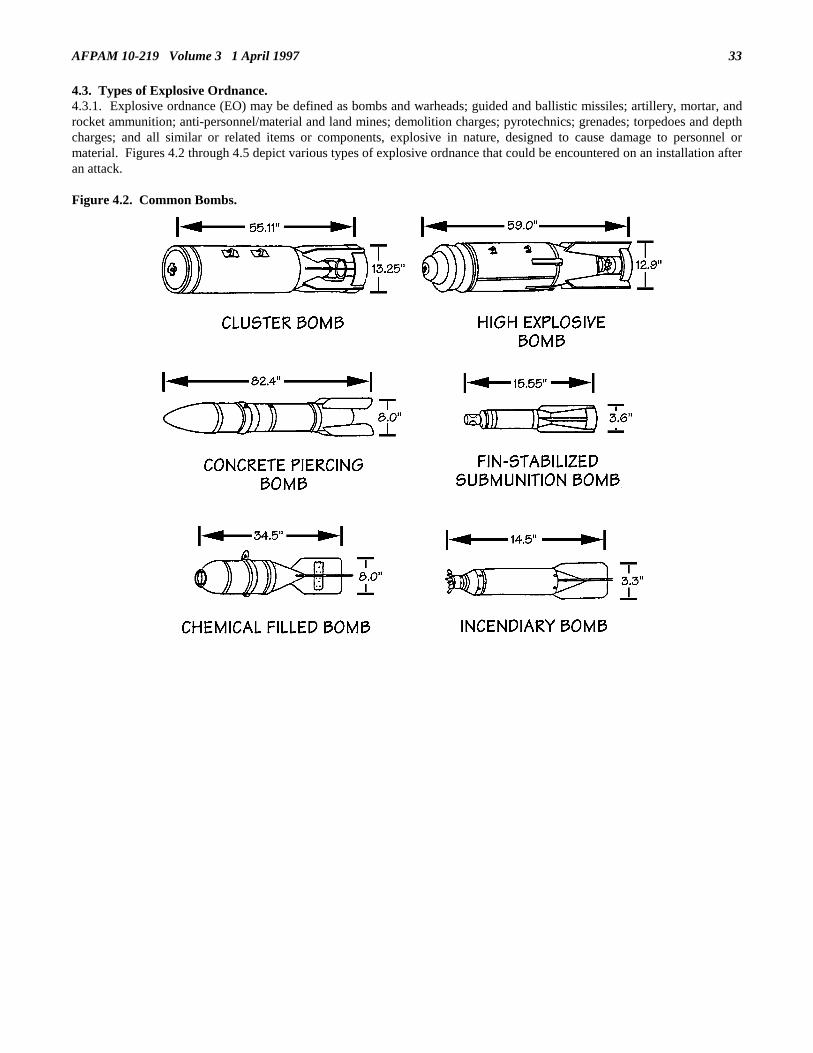
AFPAM 10-219 Volume 3 1 April 1997 33
4.3. Types of Explosive Ordnance.4.3.1. Explosive ordnance (EO) may be defined as bombs and warheads; guided and ballistic missiles; artillery, mortar, androcket ammunition; anti-personnel/material and land mines; demolition charges; pyrotechnics; grenades; torpedoes and depthcharges; and all similar or related items or components, explosive in nature, designed to cause damage to personnel ormaterial. Figures 4.2 through 4.5 depict various types of explosive ordnance that could be encountered on an installation afteran attack.
Figure 4.2. Common Bombs.

AFPAM 10-219 Volume 3 1 April 199734
Figure 4.3. Mortars and Rockets.
Figure 4.4. Grenades.

AFPAM 10-219 Volume 3 1 April 1997 35
Figure 4.5. Mines and Bomblets.
4.3.2. During certain emergency conditions, explosive ordnance will pose a significant factor limiting the progress of baserecovery operations. Explosive ordnance problems will primarily affect theater air bases, but cannot be ignored by theCONUS bases since terrorist attacks or munitions accidents could place them in a similar predicament. The major steps inany operations involving potential hazard from UXO are explosive ordnance reconnaissance, explosive ordnance safing, andexplosive ordnance removal/destruction. Although non-EOD engineer personnel are not directly involved in rendering UXOsafe, they should be prepared to assist EOD personnel in all other aspects of these operations. AFI 10-211, Civil EngineerContingency Response Planning, lists two primary tasks for non-EOD engineer personnel in operations involving explosiveordnance; assisting EOD personnel in UXO reconnaissance, and aiding in the removal of UXO that have been rendered safeand designated for removal.
4.4. Explosive Ordnance Reconnaissance. The initial step in dealing with unexploded ordnance is reconnaissance. EORinvolves investigating, diagnosing, locating, marking, and reporting of suspected EO, in order to determine the need forfurther action. Civil engineer personnel are in a position to accomplish much of the EOR effort during the initial damageassessment of the base. The following detailed discussion of EOR activities will ensure that civil engineer personnel are well

AFPAM 10-219 Volume 3 1 April 199736
informed about their responsibilities to this vital part of the base recovery mission.4.4.1. Threat Posed by UXO. Following an enemy attack there are likely to be large quantities of UXO scattered about thebase. If not located, identified, and marked, UXO poses a significant hazard to repair crews during base recovery after attack(BRAAT). EOD personnel will be in short supply since most, if not all of these specialists, will be safing those UXO creatingthe greatest danger to personnel and critical facilities. With EOD personnel concentrating their skills on render-safeprocedures (RSPs), it makes sense to leave EOR to others. Quite obviously, non-EOD engineer forces are next in line toperform this task.4.4.2. Engineer Involvement in EOR. Engineer forces are in an unique position to assist in EOR. In many cases, engineerdamage assessment and emergency repair teams are the first on the scene of an enemy attack and are able to provide first handinformation on the presence of UXO.4.4.3. Problems Associated With EOR. It should go without saying that EOR exposes engineer forces to a very hazardoussituation. Add a nuclear, biological, or chemical environment and the EOR task becomes even more formidable. Adding tothe growing list of complexities involved with EOR, the prudent BCE should expect some misidentification of UXO bypersonnel with limited ordnance recognition experience, and make allowance for the difficulty of locating and identifyingburied or hidden ordnance. It should also be expected that the same item of ordnance will be reported by different crews orpeople multiple times.4.4.4. Safety. Safe operations are especially important during EOR operations. Careless actions in the vicinity of a largeUXO can result in death or injury of personnel as well as serious damage to adjacent facilities. Personnel performing EORmust be aware of the dangers involved and must never tamper with UXO not rendered safe by EOD personnel. There areseveral other basic safety practices to be followed when performing EOR. They include:4.4.4.1. Immediately following an attack, check your surrounding area before attempting to go to your vehicle or assemblyarea;4.4.4.2. Do not enter damaged buildings which appear structurally unsound when performing EOR;4.4.4.3. Be especially alert for UXO partially hidden or buried in rubble.4.4.5. Precautions. To ensure the safety of personnel performing EOR, personnel in the surrounding area, and criticalfacilities, the following precautions are recommended:4.4.5.1. Evacuation. Evacuation of all non-essential personnel from the immediate danger area of the UXO will preventinjuries should the ordnance detonate prematurely. Evacuation also makes it easier for EOD to render the ordnance safe. Theevacuation distance will depend upon the size of the UXO and the type of structures in the area. Small UXO/sub-munitionsmay not require total evacuation, only to a safe area of the facility. Table 4.1 offers guidance on minimum evacuationprecautions for larger UXO.
Table 4.1. Minimum Evacuation Distances.
ACTION TO TAKE
RADIUS FROM UXO* BURIED UNBURIED
Evacuate: ft (m) ft (m) Steel Reinforced Buildings 90 (27) 300 ( 91) Unshielded Rooms, Unreinforced Buildings 150 (46) 600 (180)Ban Wheeled Traffic 150 (46) 450 (140)Open All Doors and Windows 300 (91) 1500 (460)*Increase by 50% if operational conditions allow.
4.4.5.2. Marking. All UXO discovered by personnel conducting EOR should be clearly marked as a hazardous area. Thismarking serves two purposes. First, it identifies the location of the UXO to the EOD team entering the area to disarm theUXO. Second, the marking warns other persons of the location of the UXO so that it may be avoided.4.4.5.3. Protective Measures. Personnel performing EOR duties on foot should wear protective body armor if available. IfEOR operations are performed from a vehicle, it should provide reasonable protection to the occupants. This protectioncould be provided by a special protective vehicle, such as the M113A2 Armored Personnel Carrier (figure 4.6), or aconventional vehicle could be modified with protective armor. For example, a truck may be fitted with steel plates around thecab area to provide protection for the occupants.

AFPAM 10-219 Volume 3 1 April 1997 37
Figure 4.6. M113A2 Armored Personnel Carrier.
4.4.5.4. Other Precautions. Additional precautions which can increase personnel and facility survivability are reinforcementof adjacent facilities in proximity of UXO and marking the danger zone. Sandbags, conex containers, timbers, 55-gallondrums, or other suitable materials may be used as reinforcing materials (figure 4.7). Roping off the area around the UXOensures that persons do not wander into the danger zone by accident. Table 4.2 provides guidance on roping off areas aroundvarious sizes of UXO. Note that these recommendations are based upon expected crater diameter and do not provideadequate safety from flying debris or blast effect to unshielded personnel. The blast efforts of UXO can be mitigated throughthe use of barriers such as sandbags, tires and berms (figure 4.8). In addition, trenching is useful for mitigating the groundshock wave produced by UXOs (figure 4.9).
Figure 4.7. Reinforced (Buttressed) Facility.
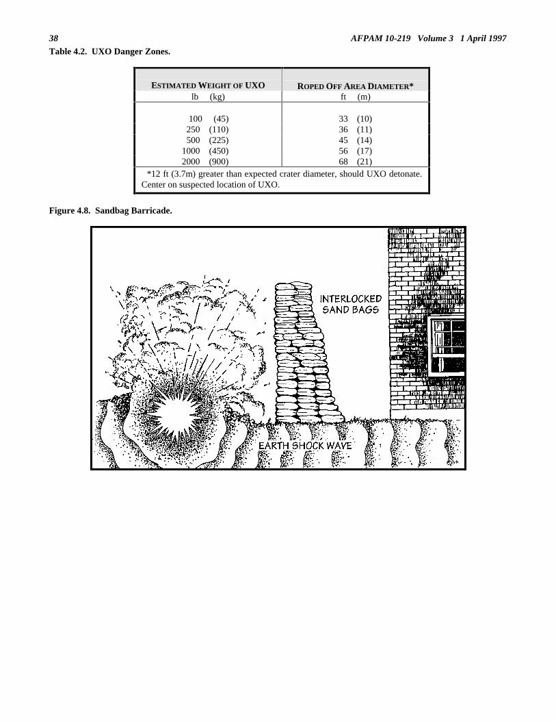
38 AFPAM 10-219 Volume 3 1 April 1997
Table 4.2. UXO Danger Zones.
ESTIMATED WEIGHT OF UXO ROPED OFF AREA DIAMETER*lb (kg) ft (m)
100 (45) 33 (10)250 (110) 36 (11)500 (225) 45 (14)
1000 (450) 56 (17)2000 (900) 68 (21)
*12 ft (3.7m) greater than expected crater diameter, should UXO detonate.Center on suspected location of UXO.
Figure 4.8. Sandbag Barricade.

AFPAM 10-219 Volume 3 1 April 1997 39
Figure 4.9. Trenching to Lessen Earth Shock.
4.4.6. EOR Equipment. The equipment used by personnel performing EOR depends on the severity of the attack and theavailability of materials. As a minimum, the following equipment is suggested:• Grid maps (or global positioning system).• UXO/hazard markers.• Radios.• Binoculars.• Body armor.• Hardened vehicle (protective armor).• Filled sandbags.• Flashlight and batteries.
4.4.7. The EOR Process. EOR involves the following basic steps:4.4.7.1. Investigating. The investigation of UXO reported from any source eliminates false reports and verifies actual EODincidents.4.4.7.2. Identifying. Using the evidence available at the site of the incident, personnel conducting EOR determine theapproximate type and size of UXO.4.4.7.3. Locating. If the UXO is not visible at the scene, use calculations and available evidence to determine theapproximate location in a structure or underground.4.4.7.4. Marking. To ensure that EOD personnel can quickly locate UXO after initial reconnaissance, each UXO should beclearly marked with plainly visible and easily recognizable markers.4.4.7.5. Reporting. Personnel performing EOR must know and follow the proper channels in reporting UXO.4.4.8. Evidence of UXO. Following an enemy attack, UXO is likely at any location on the base. However, if UXO exists, itmay be concentrated in those areas of the base heaviest hit by attacking forces. The general search area for UXO and thepossible type of UXO in the area can be determined from the effects of the munitions which did explode. The extent ofdamage to the area or facility can give personnel performing EOR an indication of the size and type of munitions used andprovide valuable clues regarding the identification of UXO. The following factors can be used to gain clues to possible typesof UXO present and the potential damage or injury that could occur if the ordnance detonated.4.4.8.1. Blast Effects. The visible blast effects from ordnance that exploded in the area can be a relatively accurateprediction of damage which could occur to adjacent facilities if accidental detonation of UXO occurred.4.4.8.2. Fragmentation. An examination of fragments in a destruction zone should indicate the type UXO that should besearched for. The presence of fragments from cluster-type bombs should alert the team to smaller explosive devices whichmay have been widely scattered from the initial point of impact.4.4.8.3. Incendiary. Incendiary ordnance can be especially destructive because it feeds fires and compounds initial damage.Evidence of incendiary ordnance should be included in the EOR report to the SRC so fire protection support can bepositioned to contain the flames if incendiary UXO detonates.4.4.8.4. Craters. The size of bomb craters is a good indication of the size ordnance involved and is an indication of the

AFPAM 10-219 Volume 3 1 April 199740
radius of damage to be expected if UXO of the same type detonates. Table 4.3 shows crater dimensions for various bombsizes.
Table 4.3. Crater Diameter (for EOR Purposes).
EXPLODED BOMB lb (kg)
CRATER DIAMETER ft (m)
100 (45) 21 ( 6.4) 250 (110) 24 ( 7.3) 500 (225) 33 (10.1) 750 (340) 40 (12.2)1000 (450) 44 (13.4)2000 (900) 56 (17.1)
NOTE: Based on old M series U.S. general purpose (GP) bombs. Not necessarilyvalid for newer bomb types.
4.4.8.5. Camouflets. The camouflet is the result of an underground burst of a bomb (figure 4.10). In areas where camoufletsare numerous, personnel performing EOR should be especially observant for evidence of buried UXO. Camouflets cancollapse and are full of poisonous gases, void of oxygen.
Figure 4.10. Deep Burst (Camouflet).
4.4.8.6. Buried UXO. Aircraft-delivered ordnance which does not explode is likely to be completely or partially buried dueto its impact force with the surface. Personnel conducting EOR must be familiar with the visible evidence of buried UXO aswell as the methods for locating and identifying the ordnance. The most common evidence of buried UXO is the entry hole.An entry hole with the absence of a camouflet, crater, or related damage is a good indication that buried UXO may be present.When such evidence is found, calculate the approximate size and location of the ordnance based upon the size of the entryhole. Table 4.4 provides information for making these approximations. A more specific location of buried UXO may bedetermined by the use of mine or metal detectors by qualified EOD technicians.

AFPAM 10-219 Volume 3 1 April 1997 41
Table 4.4. Estimation of Size and Location of Buried UXO.
HOLE OF
ENTRY
DIAMETER
(IN*)
ACTUAL
UXODIAMETER
(IN)
UXOWEIGHT
LB (KG)
PENETRATION
AVG MAXFT** FT
HORIZONTAL OFFSET
AVG MAX FT FT
9-10 7-8 100 (45) 10 30 3 1511-13 9-11 250 (110) 12 35 4 1814-17 12-15 500 (225) 15 35 5 2018-21 16-19 1000 (450) 15 40 7 2022-27 20-25 2000 (900) 20 40 10 2428-37 26-35 4000(1800) 20 40 11 24
* To get cm, multiply inches by 2.54** To get m, divide feet by 3.28
NOTE: All data based on U.S. GP bombs impacting wet clay from 15-20,000 ft. Data shown is approximate forother UXO, soils, and release altitudes.
4.4.9. Reporting.4.4.9.1. During the postattack period, base recovery activities will be directed from the SRC. The location of craters, UXO,and associated damage are plotted in the SRC to provide an overall picture of the base situation. If base manning permits,EOR teams may be established with the primary purpose of conducting comprehensive base-wide EOR. SRC personneldirect these EOR teams to areas of the base suspected of containing UXO, and once these areas have been checked, to otherunsurveyed portions of the installation. Information collected by these EOR teams is passed directly to the SRC.Requirements for specific information will vary depending upon the situation, however, table 4.5 shows the reporting formatused by NATO forces (annex F to STANAG 2143) and satisfies the most common requirements. Using the informationprovided by the EOR teams, the SRC then directs the overall operation of the EOD personnel with regard to prioritization ofrender safe and ordnance clearance requirements.

AFPAM 10-219 Volume 3 1 April 199742
Table 4.5. Explosive Ordnance Disposal Incident Report.
A. DATE AND TIME GROUP AND ORIGINATOR1. Reported by (name, position, address, telephone/call sign)2. When impacted (if known) or laid3. When discovered4. Who to contact on arrival on site if different from 1.
B. LOCATION - LAND AREAS1. Map coordinates2. Street address3. Land marks4. Type of soil
C. IDENTIFICATION1. Known EO/UXO - give nomenclature2. First seen visible UXO Description: Shape
LengthDiameter/WidthMarkingsVisible fusing
nosetailtransverse
External fittings3. Buried UXO
Estimated Identification:Evidence found at incident siteHole of entry - dimensions
4. NBC information, as applicable, for both visible and buried UXO.
D. SAFETY MEASURES TAKEN
E. ANY OTHER PERTINENT INFORMATION
F. SIGNATURE OF EOR PERSONNEL COMPLETING THIS REPORT
4.4.9.2. Engineer personnel (non-EOD) will normally not be available solely for EOR team duties since every non-EODengineer has a preassigned task on a command and control, damage assessment, firefighting, or repair crew. EOR, however,is an inherent part of these duties and every engineer must be totally capable of performing EOR taskings. As UXO are foundon the base by engineer crews, the details concerning the UXO are forwarded to the DCC which, in turn, up-channels theinformation to the SRC. Close coordination of UXO presence on the base must be maintained between the DCC and theSRC. Since engineer crews will likely be traveling to virtually all corners of the installation, they need to be kept aware ofUXO locations and hazards throughout the base. Furthermore, such coordination minimizes the potential for dual reporting ofUXO and subsequent confusion.
4.5. Explosive Ordnance Disarmament and Removal.4.5.1. UXO Safing. Non-EOD civil engineer personnel should never attempt to disarm unexploded ordnance or to moveordnance not rendered safe by EOD personnel. This phase of the UXO operation is only mentioned to outline the support thatEOD teams may require. This support could take the form of constructing protective berms around the danger zone duringdisarmament operations and providing equipment support for access to, or removal of the UXO. For example, civil engineersmight be called upon to rope off the area around the UXO, provide protective reinforcement to adjacent structures, supplyheavy equipment to remove debris for access to the UXO, or isolate major utilities in the area.

AFPAM 10-219 Volume 3 1 April 1997 43
4.5.2. Removal. Removal of UXO may occur under differing conditions. In certain situations, when the UXO location iscritical and time a vital concern, EOD personnel may move the UXO without performing render-safe procedures. In such acase EOD will drag the UXO to another location for defuzing. If time permits, EOD can disarm the ordnance before removal.Once this is accomplished, the ordnance can be removed by EOD personnel, other civil engineer forces, or simply left inplace provided it does not present an obstacle to air base operations. Understanding of UXO removal will be enhanced by adiscussion of equipment requirements and actions of the ordnance removal teams.4.5.3. Equipment. As in other recovery operations, equipment requirements must be structured to individual circumstances,but the following items are recommended minimums.• Towing devices. May consist of cables, ropes, chains, or similar items equipped with hooks and having a minimum pull
capacity of at least 6,500-7,000 pounds. Several towing devices will be required.• Handling bars.• Handling slings.4.5.4. Small Submunitions Procedures. The recommended clearance procedure is to push submunitions from the surfaceinto craters or ditches using a blade-equipped vehicle (figure 4.11). When craters or ditches are not available, use sandbags tocreate a berm to limit damage if submunitions explode.
Figure 4.11. M-60 Mass Ordnance Clearance Vehicle.
4.5.5. Large Bombs. The recommended procedure for removing large bombs is to initially drag them from the critical areawith a dump truck, snowplow, bulldozer, or similar vehicle equipped with a pintle hook. When time permits, the bombshould be loaded on a vehicle with a layer of sand or select fill and fitted with armor plating to provide fragmentationprotection to the driver. A minimum of 200 feet of cable should be used to drag the bomb to a predug hole or a bomb craterlocated at a safe distance from mission-essential areas to prevent additional damage should the bomb detonate. If the bombhas not been safed (Cat A), always disconnect the cable at the tow vehicle and abandon it to keep personnel exposure to aminimum. If the bomb has been safed, retrieve the tow line for future use.4.5.6. Buried Ordnance. The approximate location of the buried ordnance must be determined and marked. If the locationof the ordnance cannot be determined, mark the hole of entry. Do not attempt immediate neutralization or removal of thesebombs. Leave buried ordnance in place until conditions permit safe excavation.
4.6. Mass Ordnance Clearance. Earlier in this chapter small submunitions were briefly discussed and some illustrationswere presented. These types of munitions are particularly troublesome due to their small size, large numbers, and large areacoverage. Up to 2,000 of these items can be dispensed from a single bomb or canister and can be armed to explode oncontact or when disturbed by equipment or personnel. They come in various shapes and sizes and more often than not areextremely hard to detect and locate. We can expect to encounter these munitions in the same areas that standard bombs aredropped--they are highly effective in hindering access to damaged areas and delaying repair efforts.4.6.1. The presence of submunitions has a serious impact on civil engineer efforts, particularly rapid runway repair (RRR)

AFPAM 10-219 Volume 3 1 April 199744
activities and damage assessment actions. These UXO will block access to our equipment and materials, hinder ourmovement to damaged areas, and interfere with progress on the job site. This will be a particular problem during RRRoperations since relatively great distances are involved between dispersal areas, stockpiles, and the craters and spalls on theairfield pavements. Because of the distances and the wide areas our forces have to cover, our potential of encounteringconsiderable UXO of this nature is great.4.6.2. Compounding the UXO problem is the fact that the Air Force has only a limited EOD capability--it is a very smallcareer field. In wartime, it is EOD’s mission to safe and clear the massive quantities of unexploded munitions that will bepresent. However, you can probably only expect twenty or so of these individuals at your wartime base and, unfortunately,the nature of their job in wartime could lead to high attrition.4.6.3. Conceptually, after an attack some of our engineering technicians join with our EOD personnel to perform airfielddamage assessment. RRR operations can only begin in earnest after these damage assessment teams have completed theirairfield assessment actions and remaining EOD personnel have safed and cleared sufficient munitions to allow access to thecrater damage locations. The scope of these efforts could include numerous unexploded bombs and several submunitionsfields.4.6.4. Our activities relative to base facility and utility damage repair are likewise affected by mass ordnance clearancerequirements. Initially following an attack, EOD forces and many of our engineer forces will be dedicated to airfieldpavement repair efforts. Engineer damage assessment and response teams (DARTs), however, will be required to performassessment activities on critical base facilities and utilities concurrently with the on-going RRR efforts. The DARTs willobviously also encounter UXO and must be extremely observant so they can complete their assigned assessment routes andemergency actions safely. Flexibility is the key here--the DARTs may have to alter their routes periodically to by-pass UXO,yet still keep to a reasonable time schedule. Their EOR inputs are critical. These inputs will determine the priority ofcontinued EOD mass ordnance clearance once airfield pavements have been completed which, in turn, will influence thepriority of engineer response to base facilities and utilities. In all likelihood some damage repair to base facilities and utilitiescan be performed by remaining engineer forces in those areas found to be free of UXO. Full attention to such efforts,however, cannot be properly accomplished until EOD personnel have checked and cleared the base areas containingsubmunitions UXO fields.4.6.5. As stated earlier, mass ordnance clearance is an EOD responsibility in wartime. However, this does not necessarilymean that other engineers stand idly by waiting for EOD personnel to fully complete their activities. Keeping reasonablesafety practices in mind, we must begin our wartime tasks as soon as we are able. For example, start the first sets of craters onthe runway as soon as EOD personnel have progressed sufficiently down the airfield. Additionally, we must be prepared toassist EOD personnel in mass ordnance clearance in terms of providing support for movement of safed munitions off the fieldor providing sandbag support for protective berms.4.6.6. As long as an EOD capability exists on an air base, non-EOD engineer personnel should under no circumstancesattempt to remove or tamper with unexploded ordnance that has not been declared safe. Doing so could cause additionalfacility destruction and the death or injury of essential civil engineers. Firefighter/rescue personnel or fire departmentvehicles should never be selected for pure EOR or UXO removal tasks. Loss of fire protection resources could havecatastrophic consequences on the base recovery effort. Having said this, however, we must remember that in wartime manyrules may have to be bent for the sake of mission accomplishment. If the EOD function becomes attrited, non-EOD civilengineers may have to step into the mass ordnance clearance role since there is probably no one else that can. Such actionwould naturally be limited to only those areas that most affect launch and recovery and will obviously require the utmost inflexibility and ingenuity from our forces. 4.7. Summary. This chapter has discussed the various types of unexploded ordnance that may be encountered in a wartimesituation and the engineer’s role in explosive ordnance reconnaissance. It addressed the EOR process in terms of identifing,locating, marking, and reporting UXO. Also discussed were the role of EOD personnel in UXO clearance and the supportingactions required of non-EOD civil engineer personnel. Performance of proper explosive ordnance reconnaissance is anecessity--it allows EOD personnel to respond more quickly, permits other engineers to get their wartime taskingsaccomplished faster, and, perhaps most importantly, protects our equipment and the lives of our personnel.

44 AFPAM 10-219 Volume 3 1 April 1997
____________________________________________________________________________________________________
Chapter 5
CHEMICAL DEFENSE ACTIVITIES
5.1. Introduction. Is there a need for chemical defense? The answer becomes obvious when we consider the number ofnations with somewhat unstable regimes that might not think twice before unleashing various types of chemical weapons.While we have long thought of the former Soviet Union as the major potential user of chemical weapons, the proliferation ofthese weapons around the world now permits many countries relatively easy access to them and allows even the smallestnation to threaten others with chemical agent use. With U.S. military policy now centering on a regional response capabilityrather than a massive global confrontation with the Soviets, the possibility of encountering one or more of these smallernations having a known chemical warfare capability increases. As was evident during the 1991 war with Iraq, the threat ofchemical warfare use imposes operational constraints upon combat forces, psychological demands upon the local civilianpopulace, and extreme concern on the part of friends and families back in the United States. Knowing how to defendourselves and operate under chemical warfare conditions is critical in today’s military environment.5.1.1. Background. The use of chemical agents is not a recently developed mode of war. Its history goes back over 2000years. The use of gas, smoke, and water borne chemicals is documented as far back as 600 BC. "Greek Fire" was used in theMiddle Ages and toxic smoke was commonly employed throughout the 15th, 16th, and 17th centuries. Dangerous chemicalswere used extensively during World War I to kill or disable American and allied troops as they fought in the trenches ofEurope. Since that time, chemical warfare has been used sporadically in numerous other conflicts. As noted in volume I,during the 1930’s the Italians employed deadly mustard gas against Ethiopian forces with devastating results. The Vietnamesehave been suspected of using Soviet supplied poison gas weapons in Southeast Asia. In 1978-79 there were indications thatthe Vietnamese used these weapons against the Mhuong tribesmen in the mountainous areas of Northern Laos. Survivorshave provided eyewitness accounts of Vietnamese aircraft dropping fatal clouds of green and yellow poison gas, whichsickened and killed whole villages. In 1979-80 the Soviets again encouraged the North Vietnamese to use toxic gas, this timeagainst the Khmer Rouge guerrillas.5.1.2. Current Chemical Threat. Although the threat of massive conflict with the former Soviets has diminished over thelast few years, the Soviet Republics still possess the world’s best trained and equipped chemical warfare force. These forceshave intensive unit level training programs and maintain several huge chemical training areas where they undergo extensivefield indoctrination using actual chemical warfare agents. Perhaps of more concern, however, is the growing number of othercountries possessing chemical agents. While these countries may not have large armies well trained in chemical warfareactivities, some have demonstrated the intent and capability to use chemical agents on others. For example, Ethiopians andCubans have been said to have used chemical munitions on the Somalis in the Ogaden region of Ethiopia, and the Iraqis usedsimilar agents on Iranian forces during the Iran-Iraq war. The Iraqis went even a step further and used such agents on theKurdish segment of its population in an attempt to quell separatist movements. As can be seen, one does not have to be aworld superpower to possess and use chemical warfare agents.
5.2. Overview. To provide civil engineer personnel with a basic understanding of the effects of chemical warfare, thischapter will start with a discussion of the common types of chemical agents and how these materials kill or incapacitatepersonnel. Individual protective measures and precautions to be employed during a chemical attack are outlined, emphasizingthe proper use of the individual chemical ensemble and collective protection shelters. Civil engineer responsibilities forpersonnel, area, equipment, and vehicle decontamination (figure 5.1) are addressed in the final sections of the chapter.

AFPAM 10-219 Volume 3 1 April 1997 45
Figure 5.1. Decontamination Team.
5.3. Chemical Agents. As stated earlier, the primary use of chemical weapons is to kill, injure or incapacitate personnel.Chemical agents may be classified by their action and effects. The effects produced by these agents in humans are generallydose-dependent, that is, increased doses of a specific agent produce a corresponding increase in the severity of its effect.5.3.1. Basic Types of Chemical Agents. There are numerous chemical substances that may be used in a chemical warfareenvironment, but they all fall into one of four general categories. The following paragraphs identify the basic types ofchemical agents and describe their effects on human beings. The characteristics, first aid, and defense against variouschemical agents are presented in table 5-1.
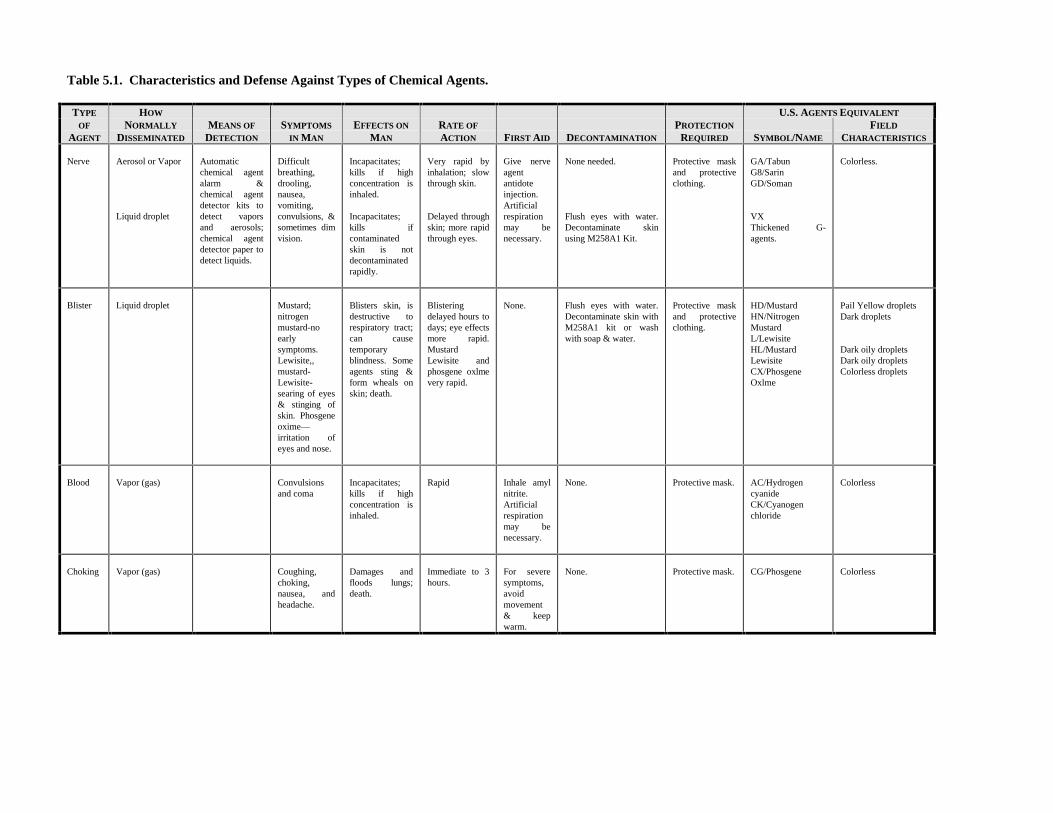
Table 5.1. Characteristics and Defense Against Types of Chemical Agents.
TYPE HOW U.S. AGENTS EQUIVALENT
OF
AGENT
NORMALLY
DISSEMINATED
MEANS OF
DETECTION
SYMPTOMS
IN MAN
EFFECTS ON
MAN
RATE OF
ACTION FIRST AID DECONTAMINATION
PROTECTION
REQUIRED SYMBOL/NAME
FIELD
CHARACTERISTICS
Nerve Aerosol or Vapor
Liquid droplet
Automaticchemical agentalarm &chemical agentdetector kits todetect vaporsand aerosols;chemical agentdetector paper todetect liquids.
Difficultbreathing,drooling,nausea,vomiting,convulsions, &sometimes dimvision.
Incapacitates;kills if highconcentration isinhaled.
Incapacitates;kills ifcontaminatedskin is notdecontaminatedrapidly.
Very rapid byinhalation; slowthrough skin.
Delayed throughskin; more rapidthrough eyes.
Give nerveagentantidoteinjection.Artificialrespirationmay benecessary.
None needed.
Flush eyes with water.Decontaminate skinusing M258A1 Kit.
Protective maskand protectiveclothing.
GA/TabunG8/SarinGD/Soman
VXThickened G-agents.
Colorless.
Blister Liquid droplet Mustard;nitrogenmustard-noearlysymptoms.Lewisite,,mustard-Lewisite-searing of eyes& stinging ofskin. Phosgeneoxime—irritation ofeyes and nose.
Blisters skin, isdestructive torespiratory tract;can causetemporaryblindness. Someagents sting &form wheals onskin; death.
Blisteringdelayed hours todays; eye effectsmore rapid.MustardLewisite andphosgene oxlmevery rapid.
None. Flush eyes with water.Decontaminate skin withM258A1 kit or washwith soap & water.
Protective maskand protectiveclothing.
HD/MustardHN/NitrogenMustardL/LewisiteHL/MustardLewisiteCX/PhosgeneOxlme
Pail Yellow dropletsDark droplets
Dark oily dropletsDark oily dropletsColorless droplets
Blood Vapor (gas) Convulsionsand coma
Incapacitates;kills if highconcentration isinhaled.
Rapid Inhale amylnitrite.Artificialrespirationmay benecessary.
None. Protective mask. AC/HydrogencyanideCK/Cyanogenchloride
Colorless
Choking Vapor (gas) Coughing,choking,nausea, andheadache.
Damages andfloods lungs;death.
Immediate to 3hours.
For severesymptoms,avoidmovement& keepwarm.
None. Protective mask. CG/Phosgene Colorless
AFPAM 10-219 Volume 3 1 April 1997 47
5.3.1.1. Nerve Agents.5.3.1.1.1. These agents directly affect the human nervous system and are highly toxic in both liquid and vapor forms. Nerveagent effects on the human body are similar whether they are inhaled or absorbed through the skin. Symptoms of nerve agentexposure include a runny nose, tightness of the chest, difficult breathing, excessive perspiration, drooling, nausea, vomiting,dimness of vision, pinpointing of the pupils of the eyes, convulsions, and death. In a vaporous state, the agent is readilyabsorbed by eyes and by nose and throat tissues. As a liquid, it readily penetrates the skin, eyes, and tissues of the body.5.3.1.1.2. When inhaled, nerve agents act rapidly, with symptoms developing within one to two minutes; when absorbedthrough undamaged skin, symptoms are slower to develop, but equally deadly. When the eyes are exposed to a nerve agentvapor the pupils become pinpointed. However, if the vapor concentration is very low, this pinpointing of the pupils may notoccur for ten minutes or more. If the only exposure to the nerve agent is skin contamination, the pupils may remain normal orbe only slightly reduced in size. Depending upon the dose received, and the adequacy and speed of first aid treatment, theeffects of nerve agents may range from mild disability to death.5.3.1.2. Blister Agents.5.3.1.2.1. Blister agents can injure eyes and lungs and blister exposed skin. Some types are painless, others sting, and stillothers cause the formation of blisters. These agents come in many forms. In the liquid state, blister agents form oily dropletsthat may vary from colorless to dark brown in color; as a vapor, they are normally invisible. The characteristics and effects ofblister agents are described below.• In liquid or vapor form these agents may burn or blister any part of the body they contact, either external or internal. The
severity of injury depends on the type and concentration of the agent, the exposure time, the weather, and the degree ofactivity of the affected individual.
• Blister agents are effective even in small quantities and can cause delayed casualties. A drop of mustard-type agent thesize of a pin-head can produce a blister 1-inch in diameter. Unprotected personnel exposed to low concentrations of theagent in vapor form over a long period of time will eventually become casualties.
• If these agents come into direct contact with the eyes, they cause redness, inflammation, and frequently temporaryblindness.
• Mustard-type agents are quickly absorbed through the skin. Depending upon the degree of contamination and prevailingweather conditions, a reddening of the affected area may occur at any time up to 12 hours after exposure. Blisters mayappear in a day or less following the reddening. Healing time varies from about 6 days to as much as eight weeks insevere cases.
• Inhalation of blister agents will cause serious damage to tissues in the mouth, nose, throat, and lungs.5.3.1.2.2. The serious effect of blister agents is not always immediately apparent. Exposure to certain mustard-type agentsmay go unnoticed due to the lack of any immediate pain and the fact that signs of injury may not appear for several hours.The vapor of other types of blister agents irritates the eyes and respiratory tract immediately. Other liquid blister agents stingthe skin and cause pain within seconds after exposure.5.3.1.3. Blood Agents. These agents are disseminated as vapors and inhaled into the body. Blood agents affect thecirculatory and respiratory systems by preventing body cells from using oxygen carried by the blood. Symptoms range fromdizziness to death. After inhaling a high concentration of blood agents, a person may become unconscious and die withinminutes.5.3.1.4. Choking Agents. Choking agents are disseminated as gases and inhaled into the body. These agents affect therespiratory system by damaging the lungs and, in extreme cases, causing them to fill with fluid. Coughing, choking, tightnessin the chest, nausea, headache, and watery eyes are common symptoms of choking agents. The individual may experience noimmediate symptoms, but suffer delayed effects 2 to 4 hours after initial exposure. Delayed effects may include rapid andshallow breathing, painful cough, discomfort and fatigue, shock, and even death.5.3.2. Chemical Agent Effects. Chemical agents cannot harm an individual unless they can enter the body. The mostcommon routes of entry are inhalation into the respiratory system or absorption through the skin.5.3.2.1. Respiratory Effects. The effects caused by inhalation of an agent are dose dependent. The dose received dependson the concentration of the agent in the air, the length of time an individual is exposed to this concentration, and the physicalactivity of the individual. The level of activity directly affects the rate of breathing and, therefore, determines the amount ofair and chemical agent inhaled in a given period of time. For example, brief exposure to a low or moderate concentration ofan agent during vigorous physical activity may cause as much harm as the same exposure to a high concentration while at rest.5.3.2.2. Skin Effects. Absorption of liquid chemical agents through the skin normally takes much longer than entry byinhalation. Harmful effects may be avoided by removing or neutralizing the liquid agent on the skin or clothes before it isabsorbed into the body. Absorption rates vary for chemical agents, but will normally be increased when the individual isphysically active and perspiring.5.3.2.3. Cumulative Effect. The effect of many chemical agents is cumulative; when repeated exposure to lowconcentrations is allowed, serious injury or death could occur.5.3.3. Effectiveness of Enemy Chemical Employment. There are a number of factors which determine the effectiveness ofa chemical attack against our forces. Civil engineer personnel must be aware of these factors to adopt a defensive posture

AFPAM 10-219 Volume 3 1 April 199748
appropriate to the chemical threat.5.3.3.1. Individual Activity. The body cooling process and the breathing rate are directly affected by the individual’sphysical activity level. In general, the higher the individual’s respiratory volume, the greater the incapacitating effects of thechemical agent through inhalation or absorption.5.3.3.2. Protective Equipment. An individual’s ability to function in a chemical warfare environment is directly related tothe degree of protection provided by protective equipment and the person’s tolerance to wearing that equipment. The bestprotective mask, hood, gloves, and overgarment are useless if the individual is not able to function without removing orloosening parts of the ensemble.5.3.3.3. Environment. Weather conditions and topography have a significant impact on the behavior of chemical agents.Extremely cold temperatures transform certain liquid agents to solids, rendering them ineffective. High winds can quicklydisperse vapor and gas agents. The most favorable weather conditions for employment of chemical agents usually occur atnight, during early morning, at dusk, and when there is a heavy overcast with light, steady winds. Smooth terrain is usuallymore favorable for the employment of chemical agents than rough terrain. Low places are better than higher elevations sincethe agents tend to linger and settle in low areas.5.3.3.4. Persistency. The persistency of a chemical agent is measured by the agent’s physical properties, prevailing weatherconditions, method of dissemination, and characteristics of the terrain, material, or equipment on which the agent is deposited.The terms "persistent agent" and "nonpersistent agent" express the relative duration of effectiveness of chemical agents in thearea of release. These terms do not refer to the duration of the effects of the agents on personnel.5.3.3.5. Training. The extremely demanding environment of chemical warfare requires realistic peacetime training to ensurethat all personnel are proficient in the use of chemical defense equipment. In contrast to the war with Iraq, we may not havethe "luxury" of several months for refresher training prior to start of a conflict. We cannot rely on predeployment lead timesto provide sufficient time for equipment checks and hands-on practice. If we are to survive a future chemical attack, it is onlyprudent to remain current on all chemical warfare defense requirements and maximize all peacetime training opportunities.5.3.4. Techniques of Chemical Attack. The purpose, type, and effect of a chemical attack can often be determined byconsidering the weapon system and the delivery technique used.5.3.4.1. Persistent Agents. If the chemical attack consists of liquid droplets from air-burst artillery shells, bomblets, bulk-filled missile warheads, or of spray from an aircraft, persistent agents are probably being used. These agents are used tocontaminate equipment and terrain and to cause personnel casualties through skin absorption. The agents may includepersistent nerve agents, blister agents, or a combination of both.5.3.4.2. Nonpersistent Agents. Nonpersistent agents are probably being used if the attack consists of vapors and aerosolsfrom point detonation, near surface detonation, artillery munitions, bombs, or bomblets. These agents normally causecasualties by entry into the body through the respiratory system. The agents may include nonpersistent nerve agents, bloodagents, choking agents, or various combinations of these substances.
5.4. Individual Personnel Protection. When civil engineer forces must operate in a hostile chemical environment,individual equipment must provide complete protection and allow a full range of movements. Detailed descriptions of thechemical ensembles are provided in Technical Order 14P3-1-141, Chemical Defense Ground Crew Ensemble. At the onset ofa chemical attack, the primary concern will be the proper use of this equipment as well as recognition of the factors whichmay limit unit effectiveness in a chemical environment.5.4.1. Limiting Factors for Personnel in Protective Ensembles. Maximum effectiveness of forces in a chemicalenvironment requires the base civil engineer (BCE) to be aware of the factors which limit individual effectiveness whileoperating in a protective chemical ensemble. Recognizing the significance of these factors, the BCE can schedule tasks in amanner that will reduce the impact on mission accomplishment.5.4.1.1. Heat Exhaustion. One of the most critical factors for personnel working in chemical protective gear is the ambientair temperature. Individuals working at moderate to heavy work rates under warm weather conditions will be highlysusceptible to heat exhaustion. The symptoms for heat exhaustion range from dizziness to fainting. The percentage ofcasualties from heat exhaustion is reduced if personnel are in good physical condition and have time to become acclimated towearing the ensemble. The survival recovery center (SRC) will direct work/rest cycles to minimize the effects of thermalstress.5.4.1.2. Fatigue. Operating in full chemical protective clothing and equipment tends to increase fatigue resulting from suchfactors as mask breathing resistance, increased body temperature from work energy and solar heat, and psychological andphysiological stress. To maintain individual alertness and efficiency during these periods, supervisors should recognize theneed for more frequent and longer rest periods.5.4.1.3. Senses. Individuals who are required to perform duties involving the senses, such as manual dexterity, visual acuity,or voice communication, will operate at decreased levels of efficiency. Increased peacetime training in protective ensembleswill increase individual proficiency in these areas.5.4.1.4. Personal Needs. Personnel cannot be expected to perform in full chemical protection gear for an indefinite period.There must be designated safe areas where they can remove these overgarments and attend to personal needs such as eating,

AFPAM 10-219 Volume 3 1 April 1997 49
caring for wounds, showering, shaving, and elimination of body wastes.5.4.2. Readiness Posture.5.4.2.1. The limitations of the chemical warfare ensemble in terms of heat retention and bulkiness have been long recognizedby the Air Force. Efforts have been underway for some time now to develop an improved ensemble that overcomes theseshortfalls. Until this improved system is fielded, however, the existing ensemble will have to remain the primary system forindividual protection. To reduce individual fatigue and permit increased efficiency when working in the ensemble, mission-oriented protective postures (MOPP) have been established. These postures range from wearing only the overgarment todonning of the full complement of ensemble components. Normally, the MOPP levels for an installation are determined bythe SRC based on intelligence data and existing conditions at the base.5.4.2.2. Due to the high intensity nature of some civil engineer base recovery activities, the standard MOPP levels may not beresponsive to mission deadlines or requirements. In such cases MOPP levels can be altered by the base command element.These alterations will allow personnel to further remove or loosen parts of their chemical protective equipment during timesof decreased threat, thereby reducing heat related casualties and maintaining a higher degree of effectiveness. This alteredreadiness posture should be based on the prevailing chemical threat, work rate, and ambient temperature range. Keep in mindthat any reduction in standard MOPP levels is a command decision, not one that is made on-scene in the field.5.4.3. Donning the Chemical Ensemble. Civil engineer Prime BEEF personnel receive annual hands-on training in the useof the chemical ensemble. This section is not intended to replace that training. Rather, it will provide general guidance andemphasize techniques which may be helpful in a chemical environment. WARNING: Due to the short time required toreceive a fatal dose of a chemical agent, donning of chemical protective gear at the first indication of chemical attack isessential. Refer to the ground crew ensemble technical order for proper donning procedures.5.4.4. Actions in the Event of a Chemical Attack. To ensure survival of a chemical attack, each individual must knowexactly what to do if such an attack occurs. The following paragraphs provide recommendations that will ensure civilengineer forces are not caught unaware at such a time.5.4.4.1. Individual Actions Preceding a Chemical Attack.5.4.4.1.1. Installation commanders direct MOPP levels and variations by weighing operational requirements against thechemical threat. This is the time to adapt to wearing protective clothing and equipment for an extended period. Despite thediscomfort, personnel should keep in mind that the amount of time required to don the protective ensemble during a chemicalattack will usually be longer than the amount of time required to receive a casualty producing dose of chemical agent.5.4.4.1.2. Individuals must remain alert and constantly aware of the chemical threat, especially if they are wearing less thanfull protective gear. Now is the time to once again review chemical alarms and signals. Alarm signals and actions can belocation specific so review procedures again upon arrival at a deployed location.5.4.4.1.3. If possible, equipment and materials should be covered to prevent contamination. Plastic sheeting, canvas, shelterhalves, ponchos, vegetation, corrugated metal or any expedient material can be used for this protection.5.4.4.2. Individual Actions During a Chemical Attack. Individuals may suffer injuries from an attack that occurs directlyat their location or upwind from that area. In either case, when an individual recognizes or is alerted to a chemical attack, thefollowing defensive actions are immediately taken:5.4.4.2.1. If not already masked, put on protective mask.5.4.4.2.2. Give the attack alarm.5.4.4.2.3. If symptoms of chemical poisoning appear, seek first aid.5.4.4.2.4. If the skin or eyes are contaminated, decontaminate them.5.4.4.2.5. If clothing and equipment are contaminated, decontaminate as soon as the situation permits.5.4.4.3. Individual Actions After a Chemical Attack. Following a chemical attack, the individual should remain in fullchemical protective gear and continue the mission. First aid should be provided to casualties in the immediate vicinity andstatus reports should be forwarded to local supervisors or commanders. If exposed skin was contaminated, decontaminationshould proceed immediately. As time permits, clothing and equipment are inspected for contamination and decontaminated asappropriate. Individuals should not remove protective clothing and equipment until advised that the area is safe.5.4.4.4. Conditions for Unmasking Following a Chemical Attack. Personnel should not unmask after a chemical orpotential attack until authorized by their immediate commander. Notification of all clear conditions will normally bedisseminated from the SRC over a giant voice broadcasting system. Outlying areas may have to be notified by radio orrunner.
5.5. Collective Personnel Protection.5.5.1. Since chemical protective clothing and equipment cannot be worn indefinitely, there must be provisions for a safe areawhere individuals can remove these garments without being subject to chemical poisoning. Some bases may have collectiveprotection shelters which provide a place for rest, eating, and other personal needs. Shelters are provided for those functionswhich do not require outdoor activity, such as command posts, communications centers, hospitals, and other organizations. Itmay also be necessary to provide protection to certain equipment. Complex electronic equipment, which can be vital toeffective accomplishment of the base mission, is highly susceptible to the corrosive action of some chemical agents.

AFPAM 10-219 Volume 3 1 April 199750
5.5.2. Civil engineer’s responsibility regarding collective personnel protective shelters is twofold. First, it must organize andmanage shelters allocated for the protection of its forces. Depending upon the situation, the shelters may be used for restfacilities, command and control, or a combination of both. Second, civil engineers are responsible for providing maintenance(beyond routine operator maintenance) on all shelter structures. This tasking may require that civil engineer craftsmen inprotective ensembles be sent into the hazardous chemical environment to make life-saving repairs on shelters. Such aresponsibility makes it essential that these individuals be highly skilled in their craft and capable of accomplishing criticaltasks while encumbered by the chemical ensemble.5.5.3. When ordered to the collective shelter, civil engineer managers must designate individuals to supervise the ingress andegress procedures. The primary concern is to prevent contamination of the toxic free area of the shelter. This isaccomplished by requiring all persons entering the shelter to doff their chemical ensembles in the proper manner. Thisdoffing will include a partial decontamination in the outer area of the shelter, followed by removal of the chemical ensembleand any contaminated clothing prior to entering the interior, toxic free area. All chemical ensembles are stored in the outercompartments of the shelter to prevent further contamination. During egress, the individual proceeds from the toxic free areato the storage area, dons the chemical ensemble, and proceeds to the outside area.5.5.4. If no collective protection shelter is available, an open air contamination control area (CCA) may be established in anuncontaminated area (on or off base) upwind of known contaminated areas. Readiness personnel will provide detailedinformation on how to establish and operate a CCA.
5.6. Decontamination Equipment and Material. Various materials and equipment may be used to assist civil engineerpersonnel in their decontamination tasks. For personnel decontamination, the M258-A1 skin decontamination kit or theM291 personal decontamination kit is used. For area, equipment, and vehicle decontamination, other materials andequipment may be required. The following paragraphs describe decontamination equipment and materials which may beuseful to civil engineer forces in a chemical environment.5.6.1. Lightweight Decontamination Apparatus (LDA). The lightweight decontamination apparatus (LDA) is aNorwegian-developed system, licensed to be produced in the United States. The SANATOR, the Norwegian designation ofthis equipment, is currently in use by many Scandinavian military units. The LDA is not intended to be a deployment item forthe Prime BEEF teams. Rather, it will be in place as base equipment or WRM at both CONUS and theater air bases. TheLDA is suitable for personnel and equipment decontamination, and can serve as a field hot water system.5.6.1.1. The LDA (figure 5.2) consists of a portable, gasoline engine-driven pump and water heating unit. The compact unitis contained in a well designed package measuring 40 x 23 x 35 inches and weighs 330 pounds. The basic LDA unit issupplemented by a 145 pound accessory kit (figure 5.3) containing hoses, cleaning wands, and shower hardware.

AFPAM 10-219 Volume 3 1 April 1997 51
Figure 5.2. Basic LDA Unit.
Figure 5.3. LDA Wands and Hoses.
5.6.1.2. An item of ancillary equipment is a rubberized fabric, self-supporting water bladder. The bladder weighs 70 poundsin the empty, collapsed state and has a capacity of 6,000 liters (1,580 gallons) when filled.5.6.1.3. The LDA is designed to draw water from any source and deliver water at controlled temperatures up to 248oF andpressures up to 100 psi. The LDA can be used with a siphon-injector nozzle to dispense liquid detergent for cleaningoperations. The LDA is unable to handle any of the standard decontamination agents. Substances corrosive to aluminum orcopper should not be used in the LDA. 5.6.2. Fire Trucks and Water Tankers. Fire trucks, water tankers, and other equipment capable of carrying or pumpinglarge quantities of water may be used for decontamination tasks. Fire trucks are especially useful. Fire vehicles are capableof moving to a contaminated area or piece of equipment, decontaminating the item with high pressure spray, and moving tothe next location. However, following an attack, fire vehicles may be unavailable due to firefighting requirements.

AFPAM 10-219 Volume 3 1 April 199752
5.6.3. Decontamination Agents. Decontamination agents assist in the decontamination process by neutralizing various toxicchemicals and reducing their adherence to certain surfaces. Most bases no longer stock standard decontaminants since theprimary decontamination apparatus (LDA) cannot dispense these agents. The primary agent used is a detergent for removingthe contamination. Household bleach can be used to neutralize contamination on a limited basis.
5.7. Personnel Decontamination. Decontamination of personnel is a vital step in the recovery process following a chemicalattack. Persons going into collective shelters must remove chemically contaminated protective gear to prevent contaminationof the interior of the shelter. Individuals who have been operating for extended periods in the chemical environment requiredecontamination and fresh clothing to prevent injury or death from the effects of the chemical agent. Decontamination mustbe performed before commanders allow forces to remove portions of their protective ensembles following the all clear signal.Although not responsible for decontamination of personnel other than their own, civil engineers must anticipate being calledupon to set-up expedient decontamination facilities and to provide assistance in the base-wide decontamination operation.5.7.1. Personnel Decontamination Facility. Personnel are normally decontaminated as they process into a collectiveprotection facility by removing their contaminated protective equipment. If no collective protection facility is available, anopen air contamination control area should be established. Contamination on skin surfaces should be removed by using theM258-A1 or M291 skin decontamination kit. When the situation allows, personnel should be allowed to shower. Readinesspersonnel can provide further guidance.
5.8. Area Decontamination.5.8.1. General Information. Large area decontamination is not feasible with current equipment. However, small areas, e.g.,outside quick turn areas, can be decontaminated if necessary. Air base functions which can continue without areadecontamination should be left to the natural decontamination process of weathering. AFI 32-4001 and AFI 10-211 state thatlimited area (roads, grounds, buildings, facilities, aprons, taxiways, and runways) decontamination is the responsibility of theBCE. Most units task the heavy repair element of the operations flight to identify, train, and equip personnel to perform areadecontamination. There are also numerous entrance ways and pieces of equipment that will require decontamination beforecivil engineer forces can accomplish their maintenance and repair duties. Common area decontamination methods arediscussed in the following paragraphs.5.8.2. Decontamination of Various Surfaces. The areas that civil engineers may be asked to decontaminate could varyconsiderably. It could be a paved surface, a vital base structure, or an area covered by grass and vegetation. Under mostcircumstances, it will be best to allow the contamination to weather and dissipate naturally.5.8.2.1. Hard Surfaces. If small hard surface areas must be decontaminated, use soapy water spray to remove thecontamination. Use of bleach will aid in neutralizing the agent.5.8.2.2. Grass and Low Vegetation. The only way to effectively decontaminate vegetation areas is by burning. Gasoline,fuel oil or other methods may be used to start the fires. Spreading dry bleach over the burned area will reduce the residualcontamination hazard. WARNING: Vaporized chemical agents mixed with the smoke created by this method may create adownwind hazard. NOTE: Natural weathering is usually preferable to burning.5.8.2.3. Buildings. Buildings are also difficult to decontaminate. Chemical agents settle into cracks and joints and are hardto dislodge. On wooden buildings, toxic chemical materials may soak into the wood and be virtually impossible to remove.When decontamination is necessary, wash with hot soapy water solution or apply high pressure steam to the surface.Normally, complete decontamination of a building is not necessary. It will generally suffice to limit decontamination effortsto the entry areas of a structure. The SANATOR unit is well suited for this task. Assign a SANATOR unit to heating and airconditioning (HVAC) personnel and ensure they are properly trained.5.8.2.4. Equipment. Civil engineer equipment, such as generators, air compressors, and other specialized gear, should bedecontaminated before they are repaired. Scrubbing with a chlorine bleach solution, washing with hot soapy water, andapplication of high pressure steam or water are all viable decontamination methods. SANATOR units, well suited fordecontamination of various types of equipment, should be assigned to the electrical, HVAC and utilities personnel so thatmajor equipment items in these areas can be serviced. WARNING: Despite basic decontamination, deadly contaminants canremain trapped in the air breathing equipment of generator engines and air compressors.
5.9. Vehicle Decontamination.5.9.1. Responsibilities. According to AFI 10-211, transportation personnel will decontaminate civil engineer vehicles andrapid runway repair support equipment. This does not relieve the civil engineer unit from being knowledgeable in equipmentdecontamination procedures. If an enemy attack is severe, transportation personnel alone may not suffice to decontaminatethe needed equipment. Additionally, civil engineer forces should be prepared to assist in the development of expedientvehicle decontamination sites.5.9.2. Vehicle Decontamination Sites. Hundreds of gallons of water and other liquid agents will be used to decontaminateequipment. Runoff from the decontamination site must be controlled to prevent contamination of water sources and otherareas off the base. If the decontamination site is established on an unimproved surface, measures must be taken to prevent the

AFPAM 10-219 Volume 3 1 April 1997 53
development of massive bogs and mud holes in which vehicles could become stuck.5.9.2.1. Decontamination Sites on Hard Surfaces. Vehicle decontamination sites on hard surfaces require no assistancefrom civil engineers other than the control of runoff. If no adequate, permanent drainage system is available, the best methodof controlling runoff is to dig channels around the lower end of the surface to direct the runoff into a sump (figure 5.4). Drybleach or other active agents can then be spread over the sump area to deactivate the toxic chemical. If runoff from thedecontamination site does not pose an immediate threat to other functions on the base, it is not necessary to devote manpowerto constructing the channels and sump.
Figure 5.4. Hard Surface Decontamination Site.
5.9.2.2. Decontamination Sites on Unimproved Surfaces. In addition to the control of contaminated runoff, a primaryconsideration for a decontamination site on an unimproved surface is the prevention of mud holes which can bog vehicles andslow the entire operation. The size of the decontamination site will depend on the size of the decontamination operation; themanpower and materials available for construction; and the time available for construction. A minimum length of 50 feet isneeded if the decontamination site is to accommodate the wash, scrub, and rinse stages of equipment decontamination.Suggested methods of accomplishing these goals are detailed in the following paragraphs.5.9.2.2.1. Crushed Stone. Digging a broad, shallow ditch and filling it with crushed stone (figure 5.5) will prevent vehiclesfrom becoming mired in large mud holes during decontamination operations. Ideally, the ditch should be gently sloped onrising ground to promote drainage. The crushed stone used should be from 1-1/2 inches to 3 inches in size. In the absence ofadequate stone for construction of this type site, a dry, rocky stream bed in the area could be used as an acceptable substitute.

AFPAM 10-219 Volume 3 1 April 199754
Figure 5.5. Crushed Stone Decontamination Site.
5.9.2.2.2. Corduroy Road. Our ancestors made extensive use of the corduroy road to overcome travel difficulties caused bybad weather. Civil engineer units can construct small sections of these roads using logs, heavy timber, or utility poles toprovide an improved surface for vehicle decontamination sites. As illustrated in figure 5.6, these items provide a stablesurface for decontamination of tracked and wheeled vehicles without creating a large muddy area.
Figure 5.6. Corduroy Road Decontamination Site.
5.10. Summary. This chapter has presented basic guidance on overcoming the effects of chemical attacks through the use ofeffective chemical defense measures. An understanding of common toxic chemical warfare agents and their effects ensurethat protective measures are adequate. All personnel must be proficient in the use of the chemical protective ensemble and beaware of equipment limitations in a chemical environment to prevent serious incapacitation or death. Use of collectivepersonnel protection shelters, if available, will enhance the civil engineer force’s ability to continue extended operations in achemical environment. To ensure that effective decontamination can take place, personnel decontamination facilities andequipment decontamination sites must be developed.5.10.1. The civil engineer responsibility for gross area decontamination actions must be limited to those areas necessary foreffective performance of the air base mission. Personnel, equipment, and time are not available to accomplish anything morethan decontamination of mission essential locations.

AFPAM 10-219 Volume 3 1 April 1997 55
____________________________________________________________________________________________________Chapter 6
DAMAGE ASSESSMENT PROCEDURES
6.1. Introduction. Damage assessment activities may be separated into two distinct areas--rapid runway repair (RRR)damage assessment and facility and utility damage assessment. RRR damage assessment involves the assessment of damageto runway surfaces, taxiway surfaces, and other facilities which directly support aircraft operations. Facility damageassessment includes assessment of damage to all other air base facilities and utility systems (figure 6.1). Resourcespermitting, both assessment operations should be conducted simultaneously and, depending on the situation, may be of equalimportance. This chapter will concentrate on facility damage assessment operations under wartime conditions; RRR damageassessment techniques are addressed in chapter 2 of volume 4 of this publication series.
Figure 6.1. Air Base Facility Damage.
6.2. Overview. This chapter provides guidance for accomplishing facility and utility damage assessment operations.Organization, team composition, and equipment are described. Assessment techniques are addressed as well as damagerecording and reporting.
6.3. Damage Assessment and Response Team Operations. Facility and utility damage assessment is the first step towardrestoring critical facilities back into service after an attack. This assessment is performed by specialized groups calleddamage assessment and response teams (DARTs). Controlled by the damage control center (DCC), DARTs determine thelocation, types, and quantities of UXO and the location, type, and extent of damage to base facilities and utility systems.They also have the responsibility to isolate damaged utility systems whenever practicable and prudent. Damage assessmentreports from the DARTs are forwarded to the DCC where they are analyzed and prioritized in accordance with the baserecovery strategy developed by the survival recovery center (SRC). Again, speed and accuracy are critical during this damageassessment process since, in many cases, facility and utility support is essential for immediate as well as sustained aircraftoperations.
6.4. Team Composition and Leadership.6.4.1. The number of DARTs to be established is variable, depending for the most part on the size of the installation to besurveyed. Nominally, three teams should be sufficient for an average size base. Manpower assets from Prime BEEF teamsconfigured in a warfighting force posture (one Lead and two Follow) can support this three-team requirement. Table 6.1reflects the basic configuration of these three teams. Although the table indicates identical teams, don’t hesitate to tailor theskill mix to your installation’s facility/utility situation. For example, if your base has a large POL complex and tank farm, youmay want to consider substituting a liquid fuels person on one of your teams. If you have a civilian workforce available, fieldmore teams.

56 AFPAM 10-219 Volume 3 1 April 1997
Table 6.1. DART Composition.
AFSNUMBER OF
PERSONNEL
32E3 13E071 13E171 13E471 1
6.4.2. Each DART is led by an officer who is responsible for communicating assessment information back to the DCC,making the decision on whether to enter a known UXO area for survey purposes or altering the assessment route, anddeciding on the appropriateness of isolating portions of damaged utility systems. Ideally, the officers chosen to head theDARTs should have educational disciplines appropriate to the type of damage to be assessed, e.g., electrical, mechanical, andstructural.
6.5. Equipment. Equipment requirements for the DARTs will depend on the means by which they will conduct damageassessment. Dedicated vehicle support for DART operations is virtually mandatory; however, the possibility exists thatassessment may have to be accomplished on foot if many vehicles are destroyed or roads seriously blocked. In such a case,the teams will be severely limited in what they can perform in the way of utility isolation, and their assessment time will begreatly lengthened. The following is the recommended equipment for DART support that should have been assembled duringthe preattack phase:• Chemical warfare ensemble, helmet and body armor.• Data recording and reporting equipment including base grid maps, utility drawings, damage assessment forms, clipboards,
writing implements, radios, and spare batteries.• Binoculars and night vision devices.• Utilities isolation tools and gear such as electrical hot sticks, fuse pullers, valve keys, etc.• Global positioning system.• Other miscellaneous equipment such as explosion-proof, plastic cased flashlights; nonmetallic measuring tapes; flags;
UXO markers; utility shut-off markers; hand tools; and first aid kit.
6.6. Assessment Technique. Current base recovery after attack (BRAAT) planning for DART operations is similar to thatused for airfield pavement assessment. Two phases of activity are envisioned--initial reconnaissance and detailed damageassessment. In Phase I, an initial gross assessment of the base is made to quickly locate areas of UXO and major facility andutility damage. The results of this preliminary survey are used to update the preplanned DART damage assessment routes andobtain a general idea of overall base damage. In detailed damage assessment (Phase II), the DARTs follow DCC-directedtravel routes from their shelter locations to various critical facilities and utilities throughout the installation. The DARTsreport the levels of damage along these routes and, in particular, at these pre-determined facilities. Detailed damageassessment requires more accurate location and description of problems than initial reconnaissance since these reports willform the basis of repair crew sizing, material and vehicle allocation, damage repair cost estimates, and, to some degree,prioritization of efforts.
6.7. Initial Reconnaissance (Phase I). The purpose of Phase I, initial reconnaissance, is to quickly assess the postattackenvironment to identify areas of major utility and facility disruption.6.7.1. Exact damage descriptions and measurements are not expected during the Phase I reporting. The same preselectedobservation posts providing data during Phase I of airfield pavement assessment (see volume 4) will also provide informationon visible facility and utility damages. The same modes of communication, i.e., radio/ telephone contact with unit controlcenters and the SRC, will be used. However, because we are now dealing with facilities and utility systems that affect morepersonnel that airfield pavements did, we can expect more inputs from personnel who are not trained or familiar with damageassessment reporting requirements. Much of the information received will be sketchy and inaccurate; therefore, DCCpersonnel will have to be prepared to ask the right questions and clarify any contradictory inputs. Expect to receive damageinputs from all types of communications modes--runners, the base telephone system, other command posts, and the SRC.6.7.2. With respect to UXO, we can expect many confusing inputs. Many personnel do not have EOR background orexperience. Most inputs will probably be in terms of generalities and close questioning will have to be done to ascertain thetype of munition that will be encountered.6.7.3. From the data obtained during the Phase I initial reconnaissance, the DCC will alter the DART assessment routes asappropriate. Once this is completed, detailed damage assessment can begin by civil engineer personnel.

AFPAM 10-219 Volume 3 1 April 1997 57
6.8. Detailed Reconnaissance (Phase II).6.8.1. Phase II damage assessment will be highly dangerous and perhaps time consuming, depending upon the extent ofdamage and size of the installation. Prior to an attack, the DARTs are sheltered in dispersed locations but maintaincommunication with the DCC either by land line or radio. Dispersed teams will maintain team integrity in the shelters;however, not more than one team should be assigned to the same shelter. This action provides a degree of redundancy in theevent one or more of the shelters is hit. If there is a choice of shelters for the DARTs, choose shelters that are closest to theDCC. This eases the reassembly of the teams and subsequent flow of information to the teams from the DCC.6.8.2. In the postattack environment, the DARTs serve as the eyes and ears of the DCC. The interface between these twofunctions must be close since the entire base recovery effort from a facilities/utilities aspect hinges on their efficiency andeffectiveness. The typical sequence of DART actions following an attack is as follows:6.8.2.1. The DCC gathers initial damage reports and annotates appropriate information on grid maps. Based on these initialreports, DCC personnel make a preliminary analysis of where major utility and facility damage has been inflicted. Tentativeutility cut-off locations are also identified.6.8.2.2. The DCC updates the previously developed damage assessment routes, if necessary, and assigns routes to theappropriate DARTs keeping in mind the technical expertise resident on each team.6.8.2.3. The DCC directs the DARTs to assemble and proceed to the DCC. The DART team chiefs pick up their assigneddamage assessment routes and receive an overview of present conditions from the DCC staff to include the status of chemicalwarfare agent presence, route updates, and information relative to probable utility shut-off requirements.6.8.2.4. DART team chiefs then brief their teams on assessment routes and known hazards or problems and begin theirdamage assessment activities. A communications check is made prior to leaving the DCC area. When the DARTs aredispatched, the DCC notifies the engineering representatives in the SRC of this action.6.8.2.5. DARTs report major problems and hazards (UXO fields, major utility breaks, fires, etc.) as they travel their routes.These major items are also plotted on the base grid maps carried by the DARTs. Radio discipline is critical and must bemaintained--report only the necessary information back to the DCC--do not report trivial items. Remember, several DARTsare in operation concurrently plus the DCC is also monitoring the rapid runway repair and firefighting operations--theinformation flow into the DCC will be staggering. It is also highly likely that DARTs will encounter casualties whileperforming their damage assessment activities. The buddy care and first aid training learned during peacetime becomesimportant here. To the extent practicable, DARTs should provide assistance to wounded personnel and accomplish rescueactions if within the capability of their teams. If possible, casualties should be turned over to their units for transport to thenearest base casualty collection point. If this cannot be done, the DCC should be informed of the casualty’s location so theappropriate unit can be contacted through command post channels. While damage assessment is the DARTs’ primary task,they cannot ignore giving aid to others--DART team chiefs are responsible for making all decisions with regard to keeping thebalance between life saving actions and rescue and damage assessment responsibilities.6.8.2.6. DARTs assess each designated critical facility/utility along their routes. At those locations where damage is found,repair/demolition estimates are developed. Estimates are transmitted back to the DCC for each critical facility/utility visitedand hard copies of estimates are also made. Data radioed back to the DCC contain only the most important information, i.e.,type and extent of damage, major materials and equipment needed, crew size and most critical AFSs, time forrepair/demolition and obvious safety hazards. The written copy covers more detail such as additional materials needed andfurther scope of damage. If a critical facility or utility has suffered little or no damage, this information should also betransmitted to the DCC. The DCC, in turn, must inform the engineering representatives in the SRC of all major damageassessment results as they are reported.6.8.2.7. At those locations where damaged utilities are found, DART members attempt to isolate the problem but only if itcan be done safely and is within the technical expertise of the team. Once a utility has been isolated, it is reported to theDCC. If a serious utility problem cannot be isolated, it is also reported to the DCC so a specialized team can be assigned thetask. Remember, these specialized teams, primarily the electrical career fields, are few in number and will spend most of theirtime after an attack attending emergency generator problems. Therefore, the DARTs should make every reasonable effort tohandle such situations without assistance.6.8.2.8. At those locations where UXO are found, DARTs should perform the standard EOR function--locate the munition(s),identify the type, report findings back to the DCC, and mark the area with ropes and appropriate signs. Under nocircumstances should DART members attempt to move an UXO even if it interferes with utility isolation or facility damageassessment. The DCC will upchannel the UXO finding data to the SRC who will, in turn, arrange for EOD support. TheDART teams, once the munitions are reported and roped off, should continue on with their assessment run. When themunitions are eventually cleared, the DCC will make the determination if and when DARTs will be sent back to assessdamage to the affected facility or utility system.6.8.2.9 As each damage assessment route is completed, DARTs report back to the DCC, handing in their hard copyassessment reports, and awaiting further taskings. If follow-on attacks are unlikely, the DCC at this time normally has threeoptions to consider pertaining to DART use. It can assign additional damage assessment actions predicated on the most
58 AFPAM 10-219 Volume 3 1 April 1997
recent damage inputs from other base personnel, task DART members to coordinate on-scene recovery efforts, or assign teammembers to specific repair crews for emergency repair activities.6.8.2.10. If follow-on attacks are about to occur, DART members should report to their original shelters and re-establish teamintegrity. DART vehicles are again dispersed and "resupplied" with any equipment, tools or materials that may have beenexpended during earlier assessment runs. The DCC updates the DART damage assessment routes/grid maps with all knowndamage and danger areas so that duplicate reports are not received during subsequent damage assessment runs and theDARTs are knowledgeable of all known problem areas prior to their next assessment tasking.
6.9. Damage Recording and Reporting.6.9.1. General Information. Once damage is assessed, it must be recorded and immediately transmitted back to the DCCfor plotting, repair prioritization, and repair team selection. The speed of reporting depends on the complete understanding ofthe information being relayed and adherence to proper radio discipline by DART and DCC personnel. Communicationsoperators and plotters in the DCC should be personnel with engineering backgrounds if at all possible. This lessens thechance of miscommunication and saves time in perhaps the most demanding and hectic period of the base recovery process.6.9.2. Priorities.6.9.2.1. The routes the DARTs take during damage assessment cannot be haphazardly determined. They should be plannedout in advance with the highest priority base areas looked at first. The facility priority list contained in the base ContingencyResponse Plan should be used as a guide. In this way the key facilities and systems on the installation will be checked anddamage that has been previously unreported will be found. If a wartime location does not have a predetermined facilitypriority list, the following can be used as a starting point.• Command posts/command and control facilities directly related to combat flying squadrons, e.g., squadron operations
building.• Communications facilities.• POL/munitions facilities.• Fire stations.• Medical facilities.• Utility plants and distribution stations.6.9.2.2. Although these damage assessment routes are determined in advance, this does not mean they cannot be altered tomeet the real world situation. They should be updated from the data received from initial damage reports. For example, ifdebris or an UXO field is blocking an access route, simply change the access route. Once the routes have been determinedand updated, they are assigned to specific DART teams. Common sense and a bit of quick analysis are required here. Routeswith known power outages and major electrical damages should be assigned to the DART containing an electrical engineerand electrical systems NCO. A route with known POL problems should be assigned to the team containing a POL specialist ifone has been placed on a team. The basic thrust is to match the specific skills contained on a particular DART with the typesof damages expected to be encountered along the assessment route.6.9.3. Damage Assessment Reports.6.9.3.1. There is much more to damage reporting than just calling in the visual battle damage inflicted upon a facility orutility. Several other factors must be addressed by DART members. For example, DARTs must make a determination ofrepair feasibility. This is an initial decision on whether a facility or utility component can realistically be repaired. If thedamage is so great that repairs cannot be made quickly or without huge expenditures of manpower and material, the facility orutility will normally be abandoned or demolished. The choice between abandoning or demolishing will usually be madebased on safety. If the condition of the facility or utility poses a major hazard, demolition would be called for; if a serioushazard does not exist, abandon the facility or utility component in-place and attend to it later after base recovery has beenaccomplished. Remember, the safety hazard determination must be based on its effect on the primary base mission. Forexample, a structurally unstable open storage shed in the back of the supply yard, while posing a serious hazard to anyoneentering it, would have little effect on the flying mission; therefore, abandon it for now. On the other hand, a structurallyunstable maintenance shop adjacent to an aircraft fuel cell maintenance area and major taxiway should be torn down and ademolition estimate from the DART would be needed. If, however, the decision is made that a facility or utility component isrepairable, a repair estimate must be made in terms of time, materials, personnel and equipment.6.9.3.2. In developing damage repair estimates DART members must be aware of the following factors:6.9.3.2.1. Repair times are critical. The quickest, least work, least material intensive repair should be identified.Workarounds are totally acceptable if a facility/utility can be satisfactorily put back in service via such methods. Remember,the goal is to make the facility or utility useable once again, not put a "peacetime" fix on it. After the threat of further attackis over, more permanent repairs can be made if necessary.6.9.3.2.2. Accuracy is important. DARTs are purposely configured with experienced personnel with varied expertise. Thisexpertise must be used in determining what has to be done. Any safety hazards that may have to be contended with duringrepair must be highlighted by the DARTs in their reports.6.9.3.2.3. Familiarity with available equipment and materials is necessary. Repair estimates must be made considering what

AFPAM 10-219 Volume 3 1 April 1997 59
resources are readily available--it cannot be assumed that resources can be immediately obtained through supply orcontracting channels. Besides knowing the "going-in" position on equipment and materials, DARTs must also maintain a"real-time" awareness of the status of major equipment and material items. This information comes from the battle staff at theDCC and is important in terms of developing solutions to repair problems involving workarounds and quick fixes. In awartime situation it is prudent to rely only on what materials and equipment are known to be readily available on base--chances are other sources of supply will not be available, much less very responsive during those first few hours after anattack.6.9.3.2.4. Knowledge of AFS capabilities is required. Repair estimates must also include an indication of work crew size.DART members must be familiar with the task capabilities of the various engineering AFSs, the multi-skilling aspects ofengineer AFSs and the general nature of the repairs to be accomplished. Specific repair taskings cannot be overmanned--manpower in a wartime situation is a precious resource.6.9.3.3. In those cases where repair of damaged facilities or utilities is not feasible and a demolition action is called for,demolition estimates are then required. DART members must consider the following when preparing such estimates:6.9.3.3.1. Safety is paramount. The reason for the demolition action in the first place is to alleviate a serious safety hazard--this hazard must be made perfectly clear in the estimate so personnel are not placed in any more danger than they are alreadyfacing in doing the job.6.9.3.3.2. Demolition actions need only be carried out to the point where the safety hazard no longer exists--final clean upcan wait. Do not worry about what the work site looks like, base beautification does not exist in wartime.6.9.3.3.3. Since demolition activities are normally pretty foreign to engineer troops, DART members must indicate anyspecial equipment needs and personnel expertise in their estimates. Of particular importance is identification of what utilitiesneed to be isolated prior to start of demolition.6.9.3.3.4. Crew size and time required for the task must be realistic and reasonably accurate. Again, like the repair estimate,the demolition task must not be overmanned. Use the multi-skilling features of engineer forces--lots of people can drive adump truck.6.9.4. Higher Headquarters Reports. Certain events must be reported to higher Air Force headquarters. These reports aregenerally completed and forwarded by the appropriate command post, but the nature of the reports will sometimes requireinput from the civil engineer force during its damage assessment activities. A detailed discussion of each report is notnecessary in this publication. An overview of the types of information supplied by the damage assessment team is sufficient.More detailed information regarding the completion of these reports is contained in AFMAN 10-206, Operational Reporting.6.9.4.1. Event/Incident Report (OPREP-3). This report is submitted to the USAF Operations Center in the Pentagonreporting any event or incident that may be of interest to the Chief of Staff, Air Force (CSAF). Typical incidents that couldtrigger an OPREP-3 report include major fire, air base attack, major natural disaster, terrorist attack, and major environmentalcontamination. The range of information that could be included in the OPREP-3 is extensive. However, for those eventswhich result in significant damage to USAF installations, the following items (as outlined in AFI 10-211) should provideadequate information from civil engineers. The DARTs are not responsible for supplying all of the information listed, butfamiliarization with the data that the BCE may have to supply for this report will facilitate the collection of essentialinformation during assessment activities. The DCC will provide specific instructions to the damage assessment and responseteams if it requires information beyond a team’s normal report.6.9.4.1.1. Extent of damage to:• Structures.• Airfield pavements.• NAVAIDS.• Utility systems.• WRM assets.• Fire protection and crash rescue vehicles.• Command, control, communications, and computer facilities and equipment.6.9.4.1.2. Support Factors:• Status of housing and dining facilities.• Status of POL storage and distribution systems.• Status of medical facilities.6.9.4.1.3. Other Information:• Restoration actions in progress or anticipated.• Estimate of repair costs.• Indication whether the repairs will be accomplished in-house or by contract.• Estimated recovery date and time.• Assistance required (Prime BEEF, RED HORSE, etc.).• Impact on combat readiness status of Prime BEEF teams.

60 AFPAM 10-219 Volume 3 1 April 1997
6.9.4.2. Employment Of Military Resources In Natural Disaster Emergencies Within United States, Its Territoriesand Its Possessions (Short Title--Tempest Rapid). This report provides information on the use of Air Force resourceswhen they are employed in natural disaster relief operations. Tempest Rapid reports are submitted to the Air Force NationalSecurity Emergency Preparedness Office and Continental US Army with informational copies to parent major command.Typical information required for this report includes the extent of damage, the amount of supplies and equipment used, and anestimate of the duration of repair crew participation in disaster relief operations. Tempest Rapid reports are submitted asthree separate reports (Tempest Rapid I, II, and III) at various stages during and following the disaster.6.9.4.3. Commander’s Situation Report (SITREP). Once initial emergency situation information is submitted using theOPREP-3 report, follow-on status is normally provided in the Commander’s Situation Report. Engineer data are usuallyincluded in the logistics portion of the report and address only major engineer problems/shortfalls. Reports generated at unitlevel are sent to the major command and the parent joint command.6.9.4.4. Bulk Petroleum Contingency Report (REPOL). This report is submitted by units to highlight damage anddeficiencies which affect bulk petroleum supplies, storage, and distribution systems. Engineer input will be necessary todefine system damage and estimated repair times. Normally generated by supply personnel, the report is forwarded throughLG channels to the major command.6.9.5. Contract Repair Documentation. Major commands play a key role in recovery activities--they seek and provide thefunding support needed for restoration actions (normally accomplished by contract). To support this effort, unit-levelengineers must be responsive in gathering and forwarding damage and requirements information. Initial damage informationis provided via OPREP-3 reporting and perhaps telephonically. The level of detail here, however, provides a broader pictureof the installation’s condition and is meant only to be an initial assessment. Once the immediacy of the natural disaster orattack situation has past, i.e., fires extinguished, personnel rescued, and basic mission restored, there will be a demand forcomprehensive information upon which to base major recovery and restoration planning and budgeting. Use thedocumentation (annotated maps, written reports, and notes) obtained during DART operations as a starting point. In mostcases a second visit to the damaged facility or utility will be necessary to properly scope out the true extent of damage. Photodocumentation is an especially good method of recording the extent of damage for justification of future repairs. Forexample, photographs can be very important to show damage to structural additions that may not have been added to originalbuilding plans. It is wise to develop an informal in-house capability for photographic support so you don’t have to depend onothers for assistance. The important point is to start your detailed damage assessment and requirements upchanneling early--aday or two after the disaster or attack. Don’t wait a week or so to start passing comprehensive repair information up throughcommand engineer channels.
6.10. Summary. Damage assessment forms the foundation for prompt and effective base recovery actions. Two primarytypes of teams that involve civil engineers are used in this activity. Damage assessment teams (DAT) concentrate on airfieldpavement damage assessment, whereas damage assessment and response teams (DART) respond to assessment requirementsassociated with base facilities and utilities. DARTs initially follow predetermined routes to survey damage at missionessential facilities and utility nodes. If damage is found, repair or demolition estimates are developed and transmitted to theDCC. These DART inputs provide the baseline data needed for assembling and tasking engineer facility and utility repaircrews. DARTs must be comprised of qualified, experienced personnel; be provided adequate communications, transport, andprotective equipment; and be completely knowledgeable of damage assessment procedures. To round out the damageassessment process, engineers serving in base command and control centers must be aware of and participate in thepreparation of the electronic reports to higher headquarters.

AFPAM 10-219 Volume 3 1 April 1997 61
____________________________________________________________________________________________________Chapter 7
EXPEDIENT UTILITY AND FACILITY REPAIR
7.1. Introduction. Immediately following a disaster or an attack by hostile forces, civil engineer personnel must begin torepair damage and restore vital services necessary for the air base to continue its assigned mission. As stated earlier, theprimary concern will be in repairing runway and taxiway damage which prevents the launch and recovery of mission aircraft.Other repairs, such as those to restore critical base facilities and utilities, must proceed at a rate commensurate with availableresources and priorities established by the command element. It may not be feasible to delay main base repairs until allrunway and taxiway repair activities are complete. If ruptured petroleum, oils and lubricant (POL) lines pose hazards tocommand and control facilities, the base population, or aircraft servicing operations, immediate response may be required todefuse the threat. A damaged or burning facility may require immediate assistance by civil engineer forces to extractentrapped personnel. Ideally, there would be adequate personnel and materials available to accomplish simultaneous recoverytasks. However, the more likely situation will find the base civil engineer (BCE) making some very prudent and judiciousdecisions to assign repair priorities to a wide range of damaged facilities and utilities whose restoration is critical to missionsupport.
7.2. Overview. This chapter will concentrate on the expedient, emergency repairs (figure 7.1) necessary to return an air baseto operational status following a disaster or enemy attack. Since procedures for the assessment and repair of damage torunway and taxiway surfaces are addressed in volume 4, this chapter will cover returning other base facilities to functionaluse. An initial discussion of basic repair considerations and unique Continental United States (CONUS) and theater ofoperations civil engineer procedures plus a review of facility and utility damage assessment actions set the stage for thesuggested repair activities. Expedient repair techniques are then addressed highlighting repairs to runway ancillaryequipment; electrical, water, gas, heating, sewage, and POL systems; and structures. Lastly, topics peripheral to expedientrepairs are discussed such as debris removal and provision of portable area lighting.
Figure 7.1. Expedient Utility Repair.
7.3. Repair Considerations.7.3.1. Safety. Safety is an important consideration when accomplishing any type of repair, but is especially important withregard to expedient repairs following an emergency. The very nature of the postdisaster or postattack environment makesrepair activities inherently dangerous. Structures may be weakened; live electrical wires may be down; explosive gas vaporsmay be present; chemical, biological, or nuclear contamination may be prevalent; and unexploded ordnance may litter thebase. Air base medical facilities may be crowded with casualties and civil engineer manpower may be at critical levels.
AFPAM 10-219 Volume 3 1 April 199762
These conditions will make it essential that resources are not further taxed by injuries caused through neglect of safetypractices. It is the responsibility of every repair crew member to perform recovery tasks with the utmost concern for safety.7.3.2. Extent of Repair. The efforts of Air Force civil engineers in the period immediately following an emergency shouldbe limited to minimum emergency repair of crucial facilities and utilities. All work should be done expediently, concentratingon functional rather than cosmetic repairs. A primary consideration when determining what repairs should be made is thefunction of the damaged facility or utility. Those damaged activities which are not essential to the base mission and do notpresent a hazard should be left as they are until time and resources permit conventional repairs.7.3.3. Basic Principles of Repair Work. Repair work following a disaster or hostile attack will go much smoother if thefollowing basic principles are remembered:7.3.3.1. Substitution. Under some circumstances, damaged utilities, particularly foreign systems, may be repaired moreefficiently by modifying the original system and substituting other materials and equipment. For example, prime itemreplacement parts for foreign electrical or water systems may not be available but the system can be restored to operation byusing approximate size or capacity U.S. standard parts. The extent of damage and available local stocks of repair parts andmaterials are governing factors.7.3.3.2. Expedient Repair. Since time is normally a limiting factor in repairs made during base recovery, rapid completionof the job is more important than economy of labor, materials, and equipment. In making improvised repairs, any suitablematerial or equipment available is used to meet immediate needs. A repaired broken water main does not have to be leakproof to be functional. Expedient repairs are improved as time and supplies permit.7.3.3.3. Cannibalization. Systems having identical or similar components may be restored by robbing parts from somedamaged units to repair others.7.3.3.4. Local Materials and Supplies. Local materials should be used whenever possible to reserve shipping space formore essential items.7.3.3.5. Use of Civilians. Civilian contract assistance, if available, can be a valuable asset during base recovery efforts.Military authorities should emphasize the extent of repair work to be done to prevent rehabilitation beyond immediate militaryneeds. If the work is being done following a hostile attack, especially in overseas locations, civilians must be carefullyselected to avoid possible sabotage.7.3.4. Repair Priorities.7.3.4.1. Immediate repair priorities should be established following a disaster or hostile attack. These priorities are based onpreviously developed contingency response plans, as well as from reports on the extent of damage following the emergencyand the immediate operational requirements facing the base. Generally, life saving operations and damage repair to therunway and taxiway system, if the base supports flying operations, must be considered as the most essential. After life savingand runway repairs, the following activities should be considered, in the listed priority, for repair efforts:7.3.4.1.1. Navigation Aids/Runway Lighting. NAVAIDS and runway lighting are vital to the operation of aircraft incontinuing the base mission. Civil engineer efforts at these facilities will consist of repairs to electrical power systems,mechanical repairs, and structural repairs.7.3.4.1.2. Command Post/Command and Control Facilities. The various command and control facilities coordinate airbase flying and non-flying activities and are essential for effective operations following a disaster or hostile attack. Civilengineer support will consist of structural and utility repairs, as well as continued expedient maintenance to ensure that thesecritical facilities remain in operation.7.3.4.1.3. Communications Facilities. Reliable communications are required for coordination of rescue and recovery effortsfollowing a disaster, and for the effective management of combat resources after an enemy attack. In either case, the civilengineer’s function will be to provide utility and structural repairs to communications facilities and any assistance that mightbe required for the communications repair crews.7.3.4.1.4. POL/Munitions Facilities. Adequate supplies of POL for both aircraft and ground vehicles will be requiredduring an emergency. Repairs to these facilities will generally be performed by fuel specialists, but the civil engineer forceshould be prepared to lend its expertise as required. Repair of munitions facilities will be crucial following an enemy attackto support future combat operations. If these facilities are damaged during a disaster, repairs can probably be delayed unlessabsolutely essential for the air base mission.7.3.4.1.5. Fire Station. Following certain disasters or an enemy attack, there are likely to be conditions which willcontribute to the start and spread of fires. Additionally, during any emergency there will be requirements for the specializedrescue skills of fire department personnel. Since the fire station must continue to function to manage these diverse activities,restoration of structural integrity and basic utilities will be essential.7.3.4.1.6. Medical Facilities. The numerous injuries that will occur during an emergency require that medical facilitiesreceive a high priority in contingency repairs.7.3.4.2. The priorities established here should not be considered as "set in concrete." It would be impossible for any prioritylisting to be inflexible considering the variations that may occur from the CONUS to theater operations and from disasters toenemy attacks. You should look upon these priorities as general guidance, realizing that the actual contingency situation willdictate specific repair priorities.

AFPAM 10-219 Volume 3 1 April 1997 63
7.3.5. Air Force Responsibilities. Air Force engineer efforts following an emergency are limited to expedient repairsrequired to return the base to an operational status. Air Force engineers will make rapid runway repairs and minimumessential emergency repairs to other critical base facilities such as command posts, communications centers, maintenancefacilities, and POL facilities. These repairs should be limited to shoring weakened buildings, securing breaks in utility lines,eliminating live electrical wires, rerouting utility lines above ground, and quick-fixing roofs, walls, and floors. Major repairand restoration beyond these efforts are U.S. Army responsibilities.7.3.6. Army Responsibilities. The Army is responsible for more extensive repairs to air bases if these repairs exceed AirForce engineer capabilities. The Army will reconstruct or replace facilities that cannot be repaired or restored.
7.4. CONUS Versus Theater Repairs. The distinction between the CONUS and theater repairs may be very slight,depending upon the nature of the disaster and the type of repairs to be accomplished. Natural and man-caused disasters canimpact both the CONUS and theater locations causing similar damage and necessitating similar repairs. Much of the damageassociated with a conventional enemy attack at a theater air base could be duplicated at a CONUS location by an earthquakeor terrorist attack. The following paragraphs will highlight some common differences between the CONUS and theater repairoperations, keeping in mind that many of the basic repair techniques will be the same regardless of location.7.4.1. CONUS Repair Operations. The primary advantage of conducting repair operations at a CONUS location is that thecivil engineer repair team is generally working with American manufactured tools, equipment, and materials. Replacementparts and materials obtained from a supplier or salvaged from damaged facilities will likely be a standard size and require lessfield modification to complete an expedient repair. Manpower support is also much more reliable. A core of civil serviceemployees with years of experience and know-how is normally available at each installation for disaster response activities.Experience has also shown that contractors working on an air base will often times unhesitatingly assist in disaster responsemeasures. Lastly, support from off-base sources, both with respect to manpower and materials, is likely to be more readilyavailable than in certain theater locations.7.4.2. Theater Repair Operations.7.4.2.1. Repairs at a theater air base following a disaster can be more complex than the same repairs at a CONUS location.Metric sizing of various components is common in overseas areas and the repair team’s tools may not be ideally suited forevery piece of equipment. Building materials and other supplies, obtained from local vendors, may be of non-standard sizesor of different qualities than those available in the United States. Electrical systems at theater bases are a major area requiringadjustment of repair methods. Although power systems should always be checked to determine voltages, 220 voltage, 50-cycle current is common throughout the world with a few exceptions such as the United States and Saudi Arabia.7.4.2.2. The differences that may exist between the CONUS and theater systems should not deter the theater civil engineerpersonnel in their repair efforts. Even the most diverse systems or materials can be made to work together through the use ofinnovative field expedient methods. For example, American made and European made pipe of slightly different sizes couldbe connected by welding, with makeshift rubber gaskets fitted to ensure a tight seal. As another illustration, damagedcomponents of an older European heating system, requiring custom-made replacement parts, could be repaired by using fieldfabricated components or parts cannibalized from a similar system.7.4.2.3. The degree of host nation support at theater locations also impacts the ability to perform emergency repair taskings.At some locations host nation support will be plentiful, equaling the capabilities of CONUS locations. At other sites hostnation support may be essentially non-existent. Host nation support for expedient repair activities could range from provisionof well trained military units and contractors with substantial amounts of materials and equipment to supply of only the bareessentials in the way of basic construction materials and unskilled labor. The differences in host nation support capabilitiesmake every theater air base an unique operating location in terms of expedient facility and utility repair.
7.5. Damage Assessment Overview. Details on damage assessment for facilities and utilities were presented in chapter 6.An overview of the process is presented here as a refresher and as a lead-in for the expedient repair techniques that follow.The overview will concentrate on theater damage assessment activities after an enemy attack, since this scenario is generallymore demanding than that of a CONUS disaster response. The assessment techniques, however, are similar for both overseasand CONUS air bases. With local modifications in team structure and prioritization, the techniques and procedures can beequally effective in a CONUS natural disaster or terrorist attack situation.7.5.1. Damage Assessment Team Composition and Control. Damage assessment is performed by specially formeddamage assessment and response teams (DARTs). Normally three such teams (four personnel each) are established at aninstallation and are usually comprised of engineer officers and technicians from the electrical, HVAC and utilities careerfields. All DARTs function under the control of the civil engineer damage control center (DCC). The DCC establishes theassessment routes the DARTs will follow. These routes are predetermined based on the locations of critical facilities andutility systems and are updated from initial reports provided by field observers and other base organizations immediately afteran attack.7.5.2. Damage Assessment Procedures. DARTs assess each designated critical facility and utility system along theirassigned routes. At those locations where damage is found, repair or demolition estimates are developed depending upon the

AFPAM 10-219 Volume 3 1 April 199764
scope of damage. These estimates are then radioed back to the DCC. The estimates include such data as type and extent ofdamage, major materials and equipment needed, crew size and critical Air Force specialties (AFS) necessary, time for repair,and obvious safety hazards such as unexploded ordnance (UXO) or downed power lines. At locations where damagedutilities are found, DARTs attempt to isolate the affected system if within the technical expertise of their teams. WhenDARTs complete their assigned routes, they report back to the DCC for further taskings. These could involve additionalassessment requirements, coordination of on-scene recovery efforts, or assignment to a specific recovery repair crew.7.5.3. Recovery Strategy. The DCC uses the damage assessment estimates to develop a facilities and utilities recoverystrategy. This strategy is based on several variables such as numbers of critical facilities and utilities damaged, extent ofdamages, severity of impact on base missions, and the base environment in terms of such items as chemical agent or UXOpresence. From this strategy the scope of repair requirements and their relative priorities will emerge. Equipment, material,manpower, and skill mix availability are then factored against these requirements and priorities to provide a plan of attack anda schedule for repair crew efforts. The next step is the physical accomplishment of expedient repair activities associated withutilities and facilities on the installation to include runway ancillary equipment.
7.6. Restoration of Runway Ancillary Equipment. Since this chapter addresses repairs other than those concerned withrapid runway repair, the first priority is given to those systems which directly support the mission of the installation.Typically this is the runway operation. Runway arresting systems, airfield lighting, and NAVAIDS are systems critical to airbase recovery and return to a fully operational status. Since mobile aircraft arresting systems and mobile airfield lightingsystems are the major topics of other chapters in this volume, this section will concentrate on expedient repairs of existingrunway ancillary equipment.7.6.1. Runway Arresting Systems.7.6.1.1. Due to the extreme stresses placed on the system during the engagement of a high speed aircraft, improvised repairson arresting systems should be conducted with extreme care. Many of the system components are specifically designed towithstand these high stresses and do not lend themselves to substitution. If there is damage to the arresting system during adisaster or enemy attack, repair teams should make every attempt to replace damaged components with parts which weredesigned specifically for use in an arresting system. These parts can be obtained from normal supply sources or cannibalizedfrom other arresting systems. Only as a last resort should improvised, field expedient components be employed. Thiswidespread lack of part substitution capability makes it incumbent upon power production personnel to build and maintainadequate bench stocks and special levels of arresting barrier components.7.6.1.2. For those occasions when replacement parts are unavailable, the following suggestions offer guidance for expedientrepairs. Under no circumstances attempt to splice a broken pendant or tape as a repair method. The stresses associated withthe engagement of a high speed aircraft will almost certainly cause a failure of the splice. Once the pendant or tape is brokenor damaged, it must be replaced. If a replacement pendant is unavailable consider using an appropriate thickness of someother type of steel cable. For example, if available at base supply, spools of steel crane cable may be an acceptable substitute.To achieve the appropriate thickness, several strands of the cable should be woven together and secured with clamps. Due toits specialized design, no alternate material is recommended for repair of the tape portion of the arresting system. The rewindmotor is a component of the arresting system that can easily be repaired by substitution. Spare parts from damaged or unusedengines of any types could be salvaged and then used to return a rewind motor to operation.7.6.1.3. There are likely to be other expedient techniques that should be considered, as long as one remembers that an aircraftmaking a landing approach at well over 100 knots exerts tremendous pressure on the arresting system. Any expedient repairmust withstand these forces or it will pose a hazard to the aircraft and its occupants.7.6.2. Runway Lighting Systems. Expedient repair of runway lighting systems is necessary to regain operational statusfollowing an emergency. There are two approaches to solving the problem of damaged airfield lighting systems: mobilelighting systems and repair of existing lighting systems. The repair of existing systems approach will be discussed here.7.6.2.1. An enemy attack on an airfield can result in extensive damage to the lighting system. Chances are that light fixtures,isolation transformers, and electrical connections will be heavily damaged in the explosion areas. Elevated fixtures will bemore severely damaged than flush mounted fixtures. In either case, light bulb filaments up and down the circuit will breakdue to the heavy concussion impact of the explosions. If the fixtures are in or near a cratered area, the damage will beextensive to both types of fixtures, and ducts will be collapsed, twisted or completely ripped out of the ground. Consequently,the conductors in the ducts will be damaged. Collateral damage can be suffered by conductors in undamaged ducts becauseof the stress created by stretching and pulling action. Concussion and earth tremor action can cause ducts to break and shear,damaging or severing the conductors. Damage to direct burial conductors in cratered areas will be equally severe. Cableswill be ripped out of the ground, broken and stretched. Many of the same types of damages could be incurred from a naturaldisaster such as an earthquake.7.6.2.2. Damage that is on the surface or in and near cratered areas will more than likely be obvious. This damage willprobably be the first repaired if it is in the area selected as the minimum operating strip (MOS). Extra care must be exercisedwhen working in cratered areas because time delay or movement sensitive bombs may have also been dropped. Work will notnormally begin until all unexploded ordnance has been identified, safed by explosive ordnance disposal personnel and

AFPAM 10-219 Volume 3 1 April 1997 65
physically removed from the work area. Some damage will not be as obvious and will require trouble-shooting the entiresystem in order to find the problems.7.6.2.3. There are four basic types of trouble that can occur in an airfield lighting system. These types are opens, shorts,grounds, and improper power. Each type is described in the following paragraphs:7.6.2.3.1. Opens. An open circuit can be described as an incomplete circuit. Somewhere the circuit is broken so that acomplete path for current flow throughout the circuit is not established. An open circuit is usually indicated when a portion orstring of lights in the circuit will not light.7.6.2.3.2. Shorts. If lamps are lighted that are not supposed to be, or if one circuit is being affected by another circuit, ashort has likely occurred between two circuits. Logically, this happens where two cables cross or where they are in closeproximity to each other.7.6.2.3.3. Grounds. Grounds are usually indicated by dim lights or blown fuses. Grounds are another type of short. With ashort to ground the insulation resistance breaks down allowing the power to pass from the conductor to ground or earthpreventing the lights from getting sufficient power.7.6.2.3.4. Improper Power. Improper power can mean voltage either too high or too low. While this type of problem is notlikely to be caused by an attack or natural disaster, it could arise during the repair process. This can happen when changingout regulators or distribution transformers. If the wrong input voltage is applied or the wrong equipment used, seriousdamage may result.7.6.2.4. In all likelihood, repairs to existing airfield lighting systems will be concentrated in three major areas--power supply,cabling, and lighting fixtures.7.6.2.4.1. Power Supply. An adequate power supply must be available to return a damaged runway lighting system tooperation. If main base power and the airfield lighting vault are still operational, the first consideration should be toreconnect or reroute feeder lines from the vault to the nearest source of base power. If the main base power system and thelighting vault backup generators are not operational, the use of other mobile base generators is the alternative. Since anoperational runway has highest priority in base recovery activities, the acquisition of needed generators should not pose aproblem. Depending on runway location, connecting the runway lighting system to an off-base commercial power supplymight also be a viable option.7.6.2.4.2 Cable Connection. An airfield lighting cable is generally a single conductor, number 8 AWG, rubber or neoprene-covered cable. It may be installed underground in a duct or conduit system or buried in the soil. If the cable is in a ductsystem, it is usually quicker and easier to pull in a new cable. Quite often you can tie the new cable to the old; and, as youpull out the old cable, pull in the new. When the new cable has been connected into the circuit, test the loop for grounds andopens before it is put back into service. With direct burial cable, on the other hand, it is normally quicker to repair the cablethan to replace it, particularly if it is only severed. This is accomplished using an in-line splice, commonly performed with aresin cast kit (figure 7.2). These permanent splice kits are made to fit different wire sizes and cable sheaths and they comewith complete instructions. When properly completed the splice will be as electrically secure and offer the same insulationquality as the original cable. In some cases a different type of splice is used, commonly referred to as a joy splice. Theseplug and receptacle connector kits (figure 7.3) are used where a quick disconnect feature is desired such as a connection to anisolation transformer. In some situations it may not be possible to make cable repairs to the existing cable because thedamage is in or near a crater that must be repaired to support rapid runway repair efforts. An attempt to make repairs wouldseriously delay the completion of the crater repair. If repairs could be made, there is the risk of redamaging the cable whenbackfilling the crater. If it is necessary to repair cables in the vicinity of a crater on the MOS, a bypass technique should beused (figure 7.4). To employ this technique the damaged section of the cable is bypassed by splicing into the cable on bothsides of the damage with a "jumper". The splicing is usually done at the lights closest to, but on either side of the damagedsection. The "jumper" method or bypass technique is also used if extensive excavation is required to locate the damage to acable and thus delay the RRR effort. In either situation "expediency" is the key word. Extra time should not be devoted toburying cable repairs or new cables unless required for safe aircraft operations. Running the cables above ground expeditesrepairs and saves considerable time for other critical repair tasks. More permanent repairs and buying of cables can beaccomplished after the emergency conditions subside. Remember, it is not essential to use standard runway lighting cable forrepairs. Any available electrical cable with a voltage and current rating equivalent to that required by the lighting system maybe substituted.
Figure 7.2. Resin Cast Kit.

AFPAM 10-219 Volume 3 1 April 199766
Figure 7.3. Molded Connector Kit.

AFPAM 10-219 Volume 3 1 April 1997 67
Figure 7.4. Airfield Lighting Cable Bypass.
7.6.2.4.3. Runway System Lights. Bulbs and fixtures are probably the most vulnerable components of the runway lightingsystem. Due to their exposed locations, these components can suffer damage from a variety of disaster or war related causes.In restoring these components to use, the first action is the simple repair or replacement of damaged parts. If the fixtures arenot damaged, replacement of broken or inoperative bulbs should suffice. If replacement bulbs are scarce or unavailable,consider leaving every other bulb out of the circuit. A general outline of the runway will have to suffice for emergencyconditions. Consideration should also be given to alternate sources of parts. If, for example, the air base has multiplerunways, bulbs and other components may be salvaged from one runway to light another. Another source for parts could bethe RRR airfield lighting set, if your wartime installation has one assigned--most of the components of this set areinterchangeable with standard airfield lighting systems. As a last resort, bulbs and fixtures which are not commonly used inrunway lighting systems may be "jury-rigged" for mission accomplishment under emergency conditions.7.6.3. Navigation Aids. Navigation aids (NAVAIDS) assist pilots in making precise approaches to the base and are vital foreffective control of air traffic. The more common types of NAVAIDS found at a base are tactical aid to navigation(TACAN), instrument landing system, beacon, radios, and windsocks. Although the operation and repair of these systems isnot a civil engineer responsibility, the civil engineer unit must be prepared to restore these functions during an emergency.Civil engineer support consists of restoring utilities and NAVAID structures and site clearing. The primary utility support tomost NAVAIDS is electrical power to operate the system. Structural support could vary from a simple platform to support ofa radio antenna to extensive shoring of a TACAN facility. Since many NAVAIDS require a clear line-of-sight for properoperation, the civil engineer force may have to assist in site clearing following a natural disaster or hostile attack.7.6.4. Airfield Utilities.7.6.4.1. At many air bases water pipes, electric cables, and other utility lines run alongside or underneath runways andtaxiways. Conventional attacks on the airfield are likely to disrupt some of these pipes and cables. If this damage is in acrater located on the MOS, the damage will be repaired by laying a bypass around the crater. Two joints will be required toconnect the bypass into the main line. Most bases maintain stocks of splice kits, clamps, fittings, and pipes of various sizesused to repair:• Fuel lines.• Water pipes.• High-voltage electrical cables.• Public address systems and telephone cables.• Compressed air lines.• Heating system lines.• Sewer pipes.7.6.4.2. Figure 7.5 illustrates the bypass repair of a utility system crossing a runway. Figure 7.6 illustrates the bypass repairof a utility line running parallel to a runway.
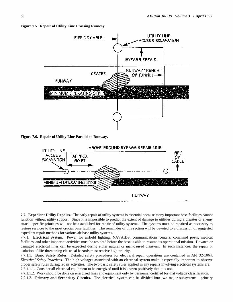
AFPAM 10-219 Volume 3 1 April 199768
Figure 7.5. Repair of Utility Line Crossing Runway.
Figure 7.6. Repair of Utility Line Parallel to Runway.
7.7. Expedient Utility Repairs. The early repair of utility systems is essential because many important base facilities cannotfunction without utility support. Since it is impossible to predict the extent of damage to utilities during a disaster or enemyattack, specific priorities will not be established for repair of utility systems. The systems must be repaired as necessary torestore services to the most crucial base facilities. The remainder of this section will be devoted to a discussion of suggestedexpedient repair methods for various air base utility systems.7.7.1. Electrical System. Power for airfield lighting, NAVAIDS, communications centers, command posts, medicalfacilities, and other important activities must be restored before the base is able to resume its operational mission. Downed ordamaged electrical lines can be expected during either natural or man-caused disasters. In such instances, the repair orisolation of life-threatening electrical hazards must receive high priority.7.7.1.1. Basic Safety Rules. Detailed safety procedures for electrical repair operations are contained in AFI 32-1064,Electrical Safety Practices. The high voltages associated with an electrical system make it especially important to observeproper safety rules during repair activities. The two basic safety rules applied in any repairs involving electrical systems are:7.7.1.1.1. Consider all electrical equipment to be energized until it is known positively that it is not.7.7.1.1.2. Work should be done on energized lines and equipment only by personnel certified for that voltage classification.7.7.1.2. Primary and Secondary Circuits. The electrical system can be divided into two major subsystems: primary

AFPAM 10-219 Volume 3 1 April 1997 69
circuits and secondary circuits. Circuits above 600 volts are generally referred to as primary or feeder circuits. Circuitscarrying less than 600 volts are usually referred to as low voltage or secondary circuits. Even in a contingency situation, workon the high voltage primary systems will be performed only by craftsmen with specialized qualifications and equipment.7.7.2. Expedient Electrical Repairs. The electrical system supporting an air base consists of several components:production, distribution, and interior wiring. Each component of the system should be considered in terms of its anticipateddamage during a contingency and by identifying expedient repair techniques deemed adequate to remedy the damage.7.7.2.1. Production Systems.7.7.2.1.1. Electrical power on an air base originates from one of two sources: connection to an off-base commercial powersystem or an independent power production plant on the base. Repair of damage to the off-base power source or the principlefeeder lines is normally the responsibility of the local power company. If the commercial source of power is interrupted,usually the only alternative is to disconnect the impaired power source from the distribution system and to substitutegenerators to power vital facilities. However, most mission essential facilities already have dedicated, standby generatorswith an automatic transfer capability to maintain operations in the event the prime power is lost.7.7.2.1.2. The extent of damage to an independent power production plant on the base will vary with the type of emergencythat has occurred. Natural disasters, such as hurricanes and tornadoes are likely to cause structural damage to the plant, aswell as disrupt the plant’s connections to the distribution system. An enemy attack will probably cause structural damage,disruption of connections to the distribution system, and may produce damage to other components of the power system, e.g.,demolished control equipment, broken turbine blades, and shattered insulators and bushings. In repairing such damage, takefull advantage of benchstocks maintained by each power plant, draw on base supply sources, or, as a last resort, try"cannibalization."7.7.2.1.3. Generators, mentioned earlier as an alternate power source, will probably be in short supply, making it imperativethat these vital assets be positioned and maintained properly. Generators should be limited to providing power to only thosefacilities that are absolutely crucial to base operations. Consider damaged or inoperative generators as a source of spare parts.Components and parts from several damaged generators may be reassembled to produce one usable machine. Equipmentother than disabled generators may serve as a source of repair parts, e.g., injectors from a diesel engine in a destroyed vehiclecan be salvaged and adapted to a generator engine.7.7.2.2. Distribution System.7.7.2.2.1. The power distribution system may consist of overhead power lines, underground power lines, or a combination ofthe two. Overhead power lines and the associated utility poles are likely to suffer extensive damage during a hurricane,tornado, or hostile attack. An underground system, although better protected from the high winds common to hurricanes andtornadoes, is still vulnerable to the effects of an earthquake, flooding, or enemy munitions.7.7.2.2.2. As stated in earlier chapters of this volume, the first action is the isolation of those damaged areas presenting life-threatening hazards to personnel or pose the potential for additional property damage. Once initial isolation is accomplished,DCC personnel, using base utility plans and maps, determine how the system can be rerouted to bypass damaged areas inorder to restore electrical power to vital base facilities.7.7.2.2.3. After damage assessment data have been posted to the base utility maps, the DCC should be able to quickly directelectrical system rerouting using the existing, undamaged circuits. However, there may still be areas where it is not possibleto supply power to critical facilities using existing wiring. In those instances, try cutting the damaged line on both sides of thedestruction and bridging the area with a new cable. If it does not pose a danger, run the new power line directly along thesurface. Otherwise, erect temporary power poles by using pieces of damaged poles, available structural members, or rawtimbers.7.7.2.2.4. When rerouting around damaged areas remember that non-standard materials can be used provided they do notjeopardize safety. If capable of carrying the required loads, wires and cables of different sizes, or normally designed for otheruses, may be substituted as expedient power lines. Additionally, conductors, wire, and other components may be salvagedfrom unimportant or damaged facilities.7.7.2.2.5. Expedient repair of transformers can be accomplished if the damage is not too extensive. Cracks or holes in thetanks of the transformers can be patched by welding, provided testing indicates that internal parts have not been damaged.Transformers can be returned to service after being thoroughly dried and when lost or contaminated transformer oil has beenreplaced. Keep in mind that oil from damaged transformers must be filtered before being reused, and that motor oil is not asatisfactory substitute for transformer use (a transformer requires a highly refined mineral oil free from moisture or otherimpurities).7.7.2.2.6. If the coils of the transformer are damaged, repair is not feasible. The coils and core of a transformer may betested by applying approximately one-fourth of the rated voltage to the low-tension coils, and observing the transformer for 15minutes. A fault is indicated by abnormal heat, smoke, or noise.7.7.2.2.7. Generally, there will not be sufficient spare transformers available to provide a one-for-one replacement fordamaged units. For example, you may not have a single-phase transformer with the capacity for the required load. In such acase it may be necessary to parallel two smaller transformers in order to supply the load (figure 7.7). This expedient solutionwill solve an immediate problem, but is not cost effective and should be replaced when the correct equipment becomes

AFPAM 10-219 Volume 3 1 April 199770
available. In a situation where three-phase power is needed, and one transformer out of the three is damaged, three-phasepower can still be provided by making what are commonly called open-delta connections. Figure 7.8 shows the open-deltaconnection when a four-wire, three-phase wye primary is involved. Figure 7.9 illustrates the connections that must be made toachieve the open-delta connection when a three-wire, three-phase delta primary is involved. Regardless of the type of primaryinvolved, these connections are used only for emergency situations and should not be constructed as permanent installations.The two transformers used in the open-delta connection will only supply 86.6 percent of their rated capacity. The totalcapacity of the bank will be only 57.7 percent of the original bank capacity.
Figure 7.7. Paralleling Single Phase Transformers.
Figure 7.8. Open-Delta with Wye Primary.

AFPAM 10-219 Volume 3 1 April 1997 71
Figure 7.9 Open-Delta with a Delta Primary.
7.7.2.3. Interior Wiring.7.7.2.3.1. Expedient repairs to the interior wiring of a structure depend on the extent of damage and the criticality of thefacility. If the facility is not critical to current air base recovery operation, delay repairs until additional resources areavailable.7.7.2.3.2. For facilities considered essential to air base operations, determine, to the minimum level, electrical servicesneeded. Does an entire structure need power, or only a small portion of it? What type of equipment will the electrical systemof the building be required to support? Will it only need minimum electrical voltage to provide lighting, or will there berequirements for specialized voltages to power large air conditioning units, refrigeration units, or X-ray machines? Forexample, there is no need to devote excessive manpower and materials to complete restoration of the base hospital’s electricalsystem if the hospital staff needs only one section of the building and one X-ray machine. In this case, electrical wiring in thissection of the building could be restored and a special high voltage cable could be run to operate the X-ray machine.7.7.2.3.3. In making expedient repairs to the interior wiring, use undamaged wiring to the maximum extent possible. Thiswill cut repair time and result in fewer exposed live circuits when the facility is returned to operation. As in the distributionsystems, damaged areas can be bypassed with new wiring to complete a vital circuit.7.7.2.3.4. In bypassing damaged areas or in running temporary lines into a structure, wiring can be run across floors and otherbuilding surfaces to expedite repairs. However, if the facility will be subject to a high volume of personnel traffic, it is betterto tack the wiring to the wall or ceiling to prevent further damage or hazards to personnel. The temporary wiring does nothave to be concealed to present a finished appearance; it only needs to be functional and out of the way of heavy traffic(figure 7.10).
Figure 7.10. Installation of Temporary Interior Wiring.
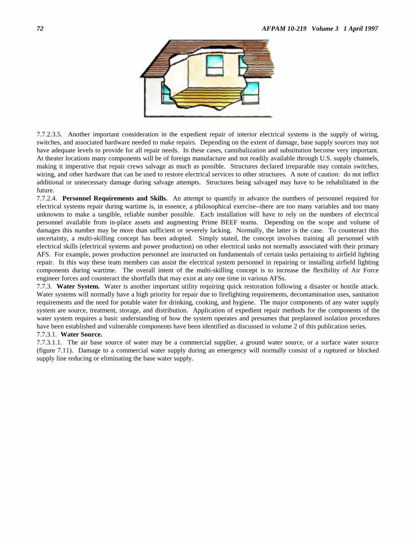
AFPAM 10-219 Volume 3 1 April 199772
7.7.2.3.5. Another important consideration in the expedient repair of interior electrical systems is the supply of wiring,switches, and associated hardware needed to make repairs. Depending on the extent of damage, base supply sources may nothave adequate levels to provide for all repair needs. In these cases, cannibalization and substitution become very important.At theater locations many components will be of foreign manufacture and not readily available through U.S. supply channels,making it imperative that repair crews salvage as much as possible. Structures declared irreparable may contain switches,wiring, and other hardware that can be used to restore electrical services to other structures. A note of caution: do not inflictadditional or unnecessary damage during salvage attempts. Structures being salvaged may have to be rehabilitated in thefuture.7.7.2.4. Personnel Requirements and Skills. An attempt to quantify in advance the numbers of personnel required forelectrical systems repair during wartime is, in essence, a philosophical exercise--there are too many variables and too manyunknowns to make a tangible, reliable number possible. Each installation will have to rely on the numbers of electricalpersonnel available from in-place assets and augmenting Prime BEEF teams. Depending on the scope and volume ofdamages this number may be more than sufficient or severely lacking. Normally, the latter is the case. To counteract thisuncertainty, a multi-skilling concept has been adopted. Simply stated, the concept involves training all personnel withelectrical skills (electrical systems and power production) on other electrical tasks not normally associated with their primaryAFS. For example, power production personnel are instructed on fundamentals of certain tasks pertaining to airfield lightingrepair. In this way these team members can assist the electrical system personnel in repairing or installing airfield lightingcomponents during wartime. The overall intent of the multi-skilling concept is to increase the flexibility of Air Forceengineer forces and counteract the shortfalls that may exist at any one time in various AFSs.7.7.3. Water System. Water is another important utility requiring quick restoration following a disaster or hostile attack.Water systems will normally have a high priority for repair due to firefighting requirements, decontamination uses, sanitationrequirements and the need for potable water for drinking, cooking, and hygiene. The major components of any water supplysystem are source, treatment, storage, and distribution. Application of expedient repair methods for the components of thewater system requires a basic understanding of how the system operates and presumes that preplanned isolation procedureshave been established and vulnerable components have been identified as discussed in volume 2 of this publication series.7.7.3.1. Water Source.7.7.3.1.1. The air base source of water may be a commercial supplier, a ground water source, or a surface water source(figure 7.11). Damage to a commercial water supply during an emergency will normally consist of a ruptured or blockedsupply line reducing or eliminating the base water supply.

AFPAM 10-219 Volume 3 1 April 1997 73
Figure 7.11. Water Sources.
7.7.3.1.2. Ground water sources, water pumped from below the surface, are probably the least vulnerable supply sources. Itcan be assumed that most natural disasters or hostile attacks would not destroy a ground water source. These emergenciescould, however, cause damage to the well and pumping systems that give the air base access to this source. Wells could bepartially filled with debris, well walls damaged, and pumping facilities damaged or destroyed entirely.7.7.3.1.3. Surface water sources can be affected by various types of emergency situations. Water-borne debris associatedwith a flood or hurricane could block water inlets to the base system; nuclear, biological, or chemical contaminants usedduring an enemy attack could make the source unusable; or conventional enemy munitions could diminish, divert, or stopaccess to a river or lake.7.7.3.1.4. Other sources of water available to the civil engineer force are sometimes overlooked. In cold weather regionsthere are vast amounts of "solid" water available in the form of snow and ice. Snow and ice melting devices can be fabricatedand used to provide excellent water supplies from glaciers and other ice formations. Base swimming pools, ornamental pools,and similar facilities containing substantial amounts of water which can be used during emergencies.7.7.3.2. Treatment Facility. The degree of treatment provided to the air base water supply will depend upon its source. Forexample, ground water is normally free of contaminants such as silt and micro-organisms. The treatment of ground water isusually minor, but it should always be thoroughly tested to determine the treatment required. Surface water sources, on theother hand, may require extensive treatment. Damage to the treatment facility can range from inundation by high flood watersto severe structural damage during hurricanes.7.7.3.3. Storage Facility. The water storage system on an air base may consist of underground reservoirs, elevated watertanks, open reservoirs, and temporary storage facilities. The most severe damage to the storage system could be a rupturecausing loss of the stored water.7.7.3.4. Distribution System. The most extensive component of the base water system is the distribution network. Thesubterranean construction protects the distribution network from certain types of disasters, while its wide-spread layout makesit more vulnerable to other emergencies. For example, high wind associated with a hurricane or tornado are not likely tobreak underground water mains, but a major enemy air attack is almost certain to disrupt some part of the distributionnetwork’s dispersed layout. Damage to the distribution system is normally confined to pumps, valves, and water mains.Water mains may be broken in several locations resulting in massive leaks causing immediate damage, as well as numeroushidden leaks producing delayed damage in the form of undermined streets or structures.7.7.4. Expedient Repair of Water System Damage. Expedient repair of the water system involves the determination ofminimum air base requirements and the establishment of a temporary supply system through bypass and repair operations.7.7.4.1. Source. If the primary source of water has been interrupted, connections to the original source must be restored or a

AFPAM 10-219 Volume 3 1 April 199774
new source developed. The primary effort should be directed to restoring the connection to the original source, normally aless time consuming effort than developing a new water supply. If the damage is not too extensive, expedient repairs or aquick bypass operation might restore the supply. If the existing source of water cannot be restored, the civil engineerrecovery force must develop alternative sources. Can the base gain access to commercial water sources in the area? Canlocal rivers or lakes provide an adequate water supply? What is the depth of an adequate ground water supply?7.7.4.1.1. Ground Water. Ground water is obtained by tapping water-bearing strata of underlying rock, sand, or gravel.The water-bearing strata is called an aquifer. To get at ground water, wells are normally drilled into the aquifers. In a fewlocations, springs may bring ground water to the surface and, under favorable geological conditions, such water could be ofexcellent quality. Development of a ground water source produces both advantages and disadvantages (table 7.1). Generally,ground water should be considered a secondary source if a source of surface water can be developed. If you are in anemergency situation where you must find a new ground water source to support your base, obviously your initial step is tolocate an area that potentially can be developed into a viable water source. The following are some tactics that can be used tohelp locate such a source.
Table 7.1. Ground Water Source Development—Advantages/Disadvantages.
ADVANTAGES
Availability. Ground water is sometimes available where surface water is not, such as in desert regions.Additionally, ground water can sometimes be located at times when there is no surface water, as in dry seasonsor during drought.Purity. Unlike surface water, ground water is normally free of major contaminants. However, springs andshallow wells have a higher risk of being contaminated than do deep wells. Do not select a ground water sourceif sources of contamination, such as pit latrines, will drain into it. A ground water source should be at least 100feet from all possible sources of contamination, and surface drainage should be directed away from it. Groundwater will usually be at a cool, constant temperature.Proximity. Wells can often be drilled in proximity to the user, eliminating water transportation problems.Resistance to Contamination. Ground water is not as vulnerable to contamination during nuclear, chemical orbiological attacks. In fact, about the only way ground water can be contaminated quickly is by placing aharmful agent directly in the well.
DISADVANTAGES
Development Time. One of the major disadvantages of developing a ground water source is the time involved.Need for a Well. If ground water is to be used, construction of a well, pit, or other excavation will be required.If standard well drilling equipment and trained personnel are available on the base, or can be found in the localarea, they should be used to sink a well. If these resources are not available, expedient methods will berequired.Detection of Ground Water. Ground water is not easily found, and it normally cannot be detected withoutspecial techniques, equipment, and experience.Pumping Requirement. After a well has been constructed, you must have one or more pumps to draw andtransport the water from the ground to the treatment location or distribution system.
7.7.4.1.1.1. Get Local Help. Your first and best approach is to get the help of a local expert. Most areas in the world willhave someone who is very familiar with finding water in that area.7.7.4.1.1.2. Check Existing Wells. Although it can be used reliably only in populated areas, search for wells which havebeen drilled by the civilian population. Not only do existing wells establish the presence of ground water, but they also canyield information on the type of aquifer and what particular method of well construction has been used successfully in thearea. If you plan to use the water from such wells, consider the water contaminated and provide appropriate treatment for it.7.7.4.1.1.3. Use Geologic and Topographic Maps. Geologic maps and reports of an area, if available, can give you a lot ofinformation. Frequently, the description of the formations on the map will state which areas usually make good aquifers.Topographic maps reveal elevation features which can also give hints of candidate water sources. If an Army engineer unit isin your area, check with it for the availability of such maps. Army units normally carry many different types of area maps.7.7.4.1.1.4. Look for Springs, Lakes, and Swamps. Lakes and swamps are sometimes created when a high water table risesabove the ground surface. Unfortunately, it is difficult to determine if a particular lake or swamp is formed this way or byrunoff. A spring, on the other hand, is a point at which ground water leaks out on the surface. The presence of a spring is anaccurate indicator of some amount and type of ground water.7.7.4.1.1.5. Look for Vegetation. In certain desert regions, the type and abundance of the vegetation growing in an area is agood indicator as to the location and depth of ground water. Use of this method must be tempered with caution. Thecorrelation of ground water with certain types and numbers of plants is never certain. The chances for success depends on the

AFPAM 10-219 Volume 3 1 April 1997 75
number of times this technique has been successfully used in a particular area.7.7.4.1.1.6. Look for Geologic Features. Some geologic features give hints of possible ground water sites. Valleys, floodplains, terraces, and alluvial fans are geologic features that often connote the presence of ground water.7.7.4.1.1.7. Drill a Test Well. In the final analysis, the best method to determine whether ground water is present is to drill atest well and run a pump test. The presence of ground water may be indicated in a formation by the type of cuttings obtainedwhile drilling, such as clean, well-rounded and well-sorted gravel. Only by running a pump test can you be assured thatenough water is present. Once a potential source of ground water has been identified, a well must be constructed to tap thesource. Attempt to obtain the assistance of a rapid engineer deployable, heavy operational repair squadron, engineer (REDHORSE) squadron, Army combat engineer unit, or local civilian drilling company as a first step. If this action does not meetyour timeframe, you must pursue an expedient method of drilling a well. Such methods will be addressed in a subsequentsection.7.7.4.1.2. Surface Water. Your location will dictate availability of surface water. Although surface water is ordinarily morecontaminated than other water sources, it is commonly selected for use because it is generally more accessible and morecapable of providing the quantities of water required. Rivers, streams, lakes and, sometimes, ponds are the most commonsources of surface water. Water from these sources is usually satisfactory for use after treatment. Both the quality andquantity of water from these sources may be subject to extreme variation due to seasonal changes in rainfall. Therefore,source selection should be based on careful investigation of average and minimum stream flow plus contamination andpollution studies. In many cases, however, such studies and data on stream flow and pollution will not be readily available.Now is the time to use common sense.7.7.4.1.2.1. In order for a surface water source to be useful it must provide an adequate quantity of water to make it feasiblefor civil engineers to divert it for base use. Smaller streams may not have an adequate flow to justify their development as awater source. Eyeball the flow of the stream at the moment. Is there a lot of water flowing? Estimate the flow rate bymeasuring stream velocity and cross section of the stream or river. If it has not rained recently, the flow rate could well besustained for a while. If flow rate is not too good, dams might have to be built to make the stream or river easier to drawfrom.7.7.4.1.2.2. Although few surface water sources will be pure enough for human consumption without treatment, there may besome sources which are so highly contaminated that it would not be feasible to use them even after treatment. This could bean especially important consideration following an enemy attack if there is suspected nuclear, biological, or chemicalcontamination. If the surface water source does not appear to be highly contaminated, however, further checks for pollutionshould still be made. Check at least two miles upstream of your proposed intake area for potential major sources of pollution.If a lake or pond is to be considered as a source, check all around its perimeter for major pollution sources. If no majorpollution or contamination problems are found, the surface water source is a candidate for development. Minorcontamination or pollution should not be a reason to reject a possible water source if proper water treatment facilities orequipment are available.7.7.4.1.2.3. The proximity of the potential surface water source to user’s location must also be taken into consideration. Thelocation of the source is very important if it is to be quickly made available for base consumption. Large quantities of puresurface water miles away from the base may be useless due to the delays that would be involved in getting it to the airfieldlocation or the lack of an adequate pipeline or hauling capability for transporting the water.7.7.4.1.2.4. Once a surface water source has been identified, some means must be developed to enable drafting of the source.In some cases the topographic and site conditions at the source will allow easy placement of intake pipes and pumps. Most ofthe time, however, some construction will be necessary in the form of small dams, reservoirs, and intake structures.7.7.4.1.2.5. The capacity of small streams to meet requirements may be increased by the construction of small dams acrossthe stream bed (figure 7.12). Another technique is to construct dams and a reservoir adjacent to a stream (figure 7.13). Theupstream dam maintains the water level of the stream, while allowing some of the water to spill over into a small collectionbasin. Water flows from the collection basin to the reservoir through an intake pipe. This pipe should be sized to deliverabout 1-1/2 times the maximum hourly demand. A screen should be placed over the inlet end of the pipe to prevent clogging.The reservoir should be sized to hold at least one day’s supply of water. The overflow dam shown in the figure controls thewater level in the reservoir by permitting excess water to flow back into the stream. Several types of intake structures can beexpediently constructed depending upon the site conditions encountered. Figure 7.14 illustrates a floating type water intakewhile figure 7.15 depicts a bottom intake. Two types of supported intakes are shown in figure 7.16.

76 AFPAM 10-219 Volume 3 1 April 1997
Figure 7.12. Small Dam Construction.
Figure 7.13. Expedient Dam and Reservoir.

AFPAM 10-219 Volume 3 1 April 1997 77
Figure 7.14. Floating Type Water Intake.
Figure 7.15. Bottom Intake.

AFPAM 10-219 Volume 3 1 April 199778
Figure 7.16 Supported Pipe Intakes.
7.7.4.2. Treatment Facilities. The expedient restoration of water treatment capabilities may consist of repairs to an existingtreatment plant or the installation of portable water treatment units. The importance of restoring the water treatment facilitywill depend upon the quality of the base water source following an emergency. If the source is relatively free ofcontaminants, treatment plant repairs or installation of portable treatment equipment may be of less importance than otherbase repairs. If water treatment is necessary and the treatment plant is beyond repair, or the base does not possess a treatmentfacility, it may be necessary to use expedient water treatment equipment. The most common expedient water treatmentsystem available to civil engineer forces is the reverse osmosis water purification unit (ROWPU). The ROWPU, figure 7.17,purifies water by forcing water under high pressure through a series of membranes to eliminate impurities. The ROWPU iscapable of removing dissolved minerals from water. Disinfection treatment is accomplished only after processing through themembrane filter elements since chlorine causes acute damage to elements. The production capability of the ROWPU will bereduced by high temperatures of the feedwater source. Although ROWPUs come in several sizes, Air Force war reservemateriel (WRM) currently includes only the 600 GPH unit.
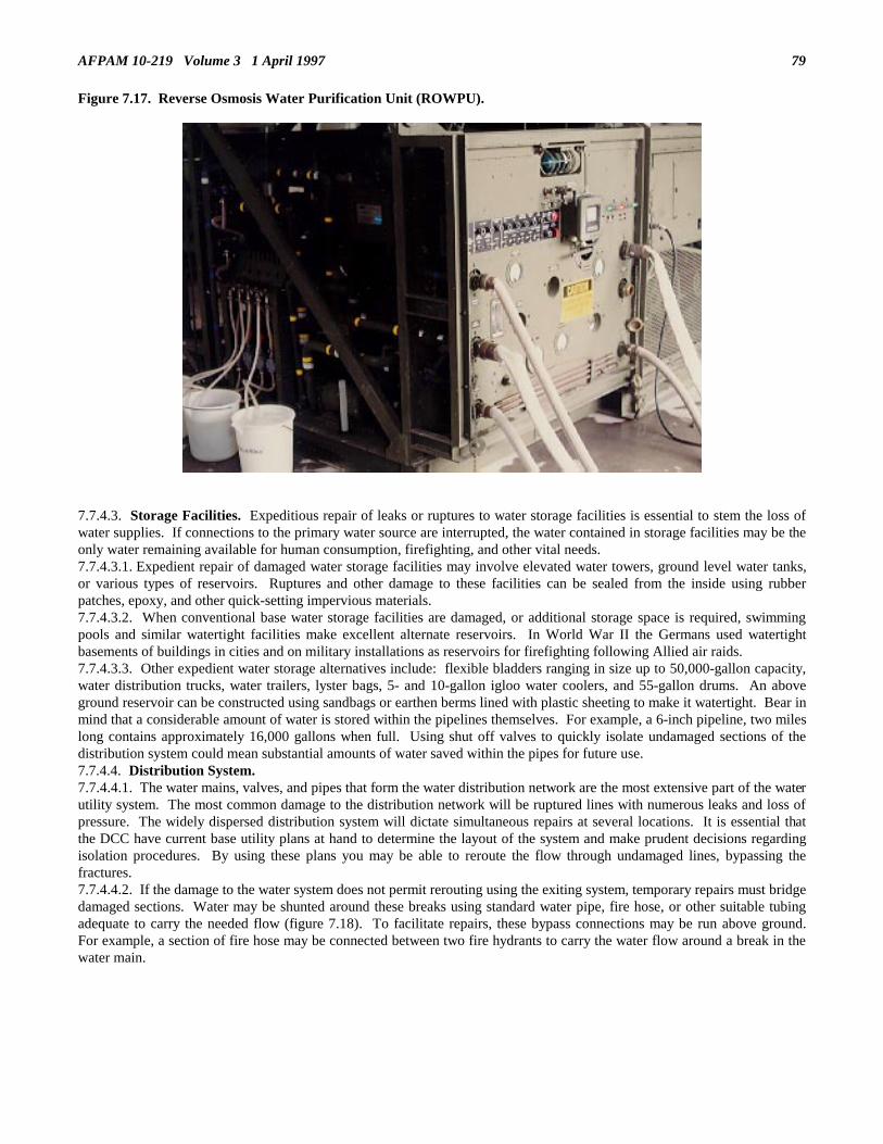
AFPAM 10-219 Volume 3 1 April 1997 79
Figure 7.17. Reverse Osmosis Water Purification Unit (ROWPU).
7.7.4.3. Storage Facilities. Expeditious repair of leaks or ruptures to water storage facilities is essential to stem the loss ofwater supplies. If connections to the primary water source are interrupted, the water contained in storage facilities may be theonly water remaining available for human consumption, firefighting, and other vital needs.7.7.4.3.1. Expedient repair of damaged water storage facilities may involve elevated water towers, ground level water tanks,or various types of reservoirs. Ruptures and other damage to these facilities can be sealed from the inside using rubberpatches, epoxy, and other quick-setting impervious materials.7.7.4.3.2. When conventional base water storage facilities are damaged, or additional storage space is required, swimmingpools and similar watertight facilities make excellent alternate reservoirs. In World War II the Germans used watertightbasements of buildings in cities and on military installations as reservoirs for firefighting following Allied air raids.7.7.4.3.3. Other expedient water storage alternatives include: flexible bladders ranging in size up to 50,000-gallon capacity,water distribution trucks, water trailers, lyster bags, 5- and 10-gallon igloo water coolers, and 55-gallon drums. An aboveground reservoir can be constructed using sandbags or earthen berms lined with plastic sheeting to make it watertight. Bear inmind that a considerable amount of water is stored within the pipelines themselves. For example, a 6-inch pipeline, two mileslong contains approximately 16,000 gallons when full. Using shut off valves to quickly isolate undamaged sections of thedistribution system could mean substantial amounts of water saved within the pipes for future use.7.7.4.4. Distribution System.7.7.4.4.1. The water mains, valves, and pipes that form the water distribution network are the most extensive part of the waterutility system. The most common damage to the distribution network will be ruptured lines with numerous leaks and loss ofpressure. The widely dispersed distribution system will dictate simultaneous repairs at several locations. It is essential thatthe DCC have current base utility plans at hand to determine the layout of the system and make prudent decisions regardingisolation procedures. By using these plans you may be able to reroute the flow through undamaged lines, bypassing thefractures.7.7.4.4.2. If the damage to the water system does not permit rerouting using the exiting system, temporary repairs must bridgedamaged sections. Water may be shunted around these breaks using standard water pipe, fire hose, or other suitable tubingadequate to carry the needed flow (figure 7.18). To facilitate repairs, these bypass connections may be run above ground.For example, a section of fire hose may be connected between two fire hydrants to carry the water flow around a break in thewater main.

AFPAM 10-219 Volume 3 1 April 199780
Figure 7.18. Water Bypass Repair.
7.7.4.4.3. Smaller leaks in the distribution network can be quickly sealed using temporary sleeves or wooden plugs. If timepermits and the necessary tools are available, holes are reamed to a larger size, threaded, and fitted with a standard metal pipeplug.7.7.4.4.4. Until the normal distribution system is repaired, provisions must be made for dispensing water into hand-carriedcontainers. A 2-inch header with four 3/4-inch taps on each side, spaced 10 feet apart, serves 8,000 to 10,000 persons with anemergency supply. Tank trucks, water trailers, or 55-gallon drums on cargo trucks can serve as mobile water distributionsystems.7.7.4.5. Disinfection.7.7.4.5.1. One of the most important considerations following repairs to the water utility system is disinfection of systemcomponents which carry potable water. The water system is easily contaminated by events that occur during various disasters.Fractures in adjacent water mains and sewers can allow the contamination from the sewer to seep into the water system.Contamination may result when pressure within the system is reduced by broken mains, heavy draft for firefighting, valveclosures, or supply failures. Contamination may also enter open mains or fractures during repair operations. Finally, duringenemy attacks or terrorist activities, saboteurs may deliberately contaminate water supplies.7.7.4.5.2. Disinfection ensures that bacterial contamination is rendered harmless before the system is put back into use.Disinfection is normally accomplished by increasing the chlorine level until a constant residual level is obtained at a pointmost distant from the treatment source. Once the system is found to be contamination free, the chlorine levels can be returnedto normal.7.7.5. Natural Gas System. Damage to a base natural gas system must be dealt with rapidly to ensure that this potentiallydangerous material is effectively contained. The most expedient method of dealing with gas system leaks is to shut off the gassupply at the main access point to the base. Since gas is normally not essential for base operations, the system can usuallyremain off until time and resources are available for repairs.7.7.6. Emergency Cut-off Procedures. If it is not possible to cut off the gas supply through the use of existing valves, gasmain bags or gas stoppers may be required. Gas main bags are canvas or rubber bags which can be inserted into a gas mainand inflated until they fill the pipe and stop the gas flow. The gas stopper consists of oiled or rubber coated canvas stretchedover a flexible steel frame. The edge of the stopper forms a seal with the interior of the gas main thereby stopping the gasflow. To seal a main with a gas bag, the rubber or canvas bag is inserted through a hole in the main (a hole created bydamage, removal of a riser, or access port). If the interior of the pipe is coated with tar or oil, canvas bags are necessary. Thebag is then inflated through a piece of attached tubing until it fills the pipe and stops the gas flow. To use a gas stopper, theframe is squeezed together and inserted into the hole in the gas main. After the stopper is in the pipe, it is restored to itscircular shape through the use of wire levers attached to the frame. The gas stopper can then be adjusted to shut off the gasflow. In larger mains, it is safer to use both bag and stopper.7.7.7. Expedient Repairs of Gas Systems. As mentioned earlier, it is best to simply cut off gas systems and make
AFPAM 10-219 Volume 3 1 April 1997 81
permanent repairs later when the emergency has subsided. However, certain conditions may call for some immediateexpedient repairs to prevent danger to personnel or to provide limited gas service.7.7.7.1. Venting of Gas Accumulations. After the main gas supply is shut off, immediately check buildings and other areasfor the presence of dangerous gas accumulations. The presence of gas can be detected through the use of special gasdetection devices such as a combustible gas indicator or, when no detection instrument is available, by the individual’s senseof smell. The sense of smell cannot always be depended on to detect leaks because gas can lose its odor while travelingthrough the ground. Any accumulations should be vented to the outside to reduce the potential for asphyxiation or explosion.7.7.7.2. Repair of Broken or Punctured Gas Pipes. There may be conditions following an emergency when gas must besupplied to certain facilities for essential operations. For example, the dining hall may have no alternate method of preparingfood for the recovery force; or the hospital may need hot water for crucial medical services and have no other source ofenergy for water heaters. During periods of cold weather, gas may be the only source of heat for certain mission-critical basefacilities. Under any of these conditions, leaking or ruptured gas lines may require patching. If the leak is small and involveslow pressure gas pipes, a sealant may be used in conjunction with a pressure mold to close the opening. The sealant should bea product which does not breakdown in the presence of natural gas. Larger leaks and pipe breaks can be repaired usingvarious types of mechanical clamps.7.7.7.3. Safety. Safety has been a predominant theme throughout this chapter on expedient repairs, but it should be greatlyemphasized with regard to gas system repairs. The potential for asphyxiation or explosion during encounters with gas leaksmakes it imperative that the repair crew exercise extreme caution. Personnel should not enter confined areas with high gasaccumulations unless they are equipped with self-contained breathing apparatus. No open flame from cutting torches,cigarette lighters, or similar devices will be used in a gaseous environment. Additionally, the repair crew must be careful notto generate sparks in the vicinity of a gas leak. A good rule of thumb is not to enter any area where the mixture of air and gasis at, or approaches, the lower explosive limits. Taking a few extra minutes to properly vent the area will greatly reduce thedanger to personnel.7.7.8. Heating Systems. Depending upon weather conditions at the time of a disaster or hostile attack, repairing damage tothe heating system can range in importance from critical to insignificant. The extent of damage can span the gamut fromnothing whatsoever to total destruction. However, unless the air base is undergoing a period of severe cold, repairs to heatingsystems servicing non-mission essential facilities can probably be delayed through the use of space heaters and the wearing ofadditional clothing. However, if repairs must be made, concentrate on minimum efforts necessary to return some measure ofheat to base facilities. It is not necessary to attain pre-disaster comfort levels following an emergency; a partial return of heatcan raise temperatures to a level that will allow normal operations if personnel are warmly clothed.7.7.8.1. Central Systems. For those bases that have a large central heating system, damage following an attack or disastercan be widely dispersed. It may well involve the production plant, as well as the distribution system. The feasibility ofconducting expedient repairs to the heating system will depend to a great degree upon the amount of damage incurred. Forexample, if an earthquake or bomb explosion causes a large rupture of the central boiler, it is unlikely that expedient repairtechniques will suffice. On the other hand, a break in one of the pipes leading from the boiler could probably be readilyrepaired expediently. Fortunately, the inherent strength of materials used to contain the pressure within the system also servesto protect the system from external damage as well.7.7.8.2. Individual Systems. Bases without a central heating system generally feature individual building systems. Thegreat advantage of these independent units is that damage is limited to the system which supports a single building. Some ofthe more common damage to expect include duct work or distribution line separations, control failures, and supply servicedisruptions.7.7.9. Expedient Repairs to Central Heating Systems.7.7.9.1. Production Plant Repairs. Expedient repair of heat production plants may be delayed pending structural and/orelectrical support. Damaged walls may have to be shored to prevent structural collapse, or electrical utility service may haveto be restored to power control and monitoring devices. From a mechanical perspective, broken pipes may need to berepaired or replaced, damaged automatic controls may have to be bypassed with manual ones, and internal cannibalizationmay have to be accomplished in order to get some boilers back in operation. As stated earlier, however, if a plant’s boilershave sustained significant damage, the production plant is probably beyond immediate repair.7.7.9.2. Distribution System Repairs. The high heat and pressure associated with most heating systems are characteristicsthat preclude the use of many expedient repair methods and materials used to otherwise correct water distribution systemdamage. For example, temporary connectors, such as fire hoses, which are effective in bridging damage to a waterdistribution system, may not tolerate the high temperatures and pressures of a heat distribution line. Similarly, a standardsealer or joint compound which could patch a water leak will break down when applied to a steam line. If repairs areattempted, only materials which have been specifically designed to withstand the stresses imposed by heating systems shouldbe used. Pipe replacement and welding are the most common repair techniques used to correct distribution system problems.Caution must be exercised, however, since welding of high pressure vessels is a specialized technique and requires substantialexperience. You just cannot slap together a steam line, even in a contingency mode, and expect it to work. In overseas areasexpect to encounter older systems which may contain components that are no longer in production. Repair parts for these

AFPAM 10-219 Volume 3 1 April 199782
facilities may have to be custom fabricated or cannibalized from other systems. Most locations, however, should have anemergency stock of heating system materials. Tap this source as much as possible.7.7.10. Expedient Repairs to Individual Systems. As mentioned earlier, the great advantage of these independent units isthat damage is limited to the system which supports a single building. While the types of individual heating systems youmight encounter on air bases worldwide are numerous, general repair concepts are for the most part universally applicable.The basic question becomes whether to repair or not repair.7.7.10.1. Do Not Repair. The easiest way to deal with a damaged individual heating system is to ignore it. If the weatherpermits, or the facility is not critical to the base mission, delay repairs until emergency conditions are essentially over.Another quick alternative when extensive repairs are required is to move personnel into a nearby building with a workingheating system.7.7.10.2. Repair. Expedient repairs to an individual heating unit are generally less complex than repairs on a large centralsystem. Damage is confined and easy to determine since the independent system does not involve a dispersed network.Components are smaller, making it easier for repair crew members to install replacements. Also, spare parts may be morereadily available from base supply and local vendors. Furthermore, since there often are many facilities containing similarindividual heating systems, there are more opportunities for cannibalization of parts from low priority buildings.7.7.11. Alternative Heating Sources. If attempts to repair existing base heating systems fail, temporary heating sources canbe provided for mission-essential facilities. Remember, however, alternate heat sources can be dangerous and requirefrequent checks and servicing. As time permits, systems should be repaired by using existing stocks or cannibalizedmaterials, thereby freeing the portable heaters for use elsewhere.7.7.11.1. Space Heaters. Various types of space heaters provide an alternative to a central or individual heating systems.Fuel-fired heaters can be used in large open buildings if odor is not objectionable and explosive vapors are not present. Openflame heaters are dangerous, especially the unvented type. If they are to be used, catalytic types are the safest. Electricheaters provide a safe alternative to open flame units provided temporary wiring and power sources can handle the extra load.Space heaters can be obtained from various sources. Harvest Eagle assets, if available, contain units (figure 7.19) which canbe used for either permanent structures or tents. Commercial space heaters may be available from local vendors. Some baseunits may also have portable shop heaters which can be reassigned to more critical facilities.

AFPAM 10-219 Volume 3 1 April 1997 83
Figure 7.19 Harvest Eagle Heater.
7.7.11.2. Cart-type Ducted Heaters. Cart-type ducted heaters provide an excellent alternate heat source becausecombustion stays outside the structure being heated. The units may be available from organizations on base, such asaerospace ground equipment (AGE) or communications squadrons, after the units’ requirement for aircraft sorties and othervital operations have been met.7.7.12. Improvised Heaters. The use of improvised heaters should be avoided except in cases of extreme cold and where noother alternative exists. The primary dangers inherent with improvised heating systems are fire hazard potential and thepossibility for asphyxiation. Caution must be taken to ensure that dangerous fumes are vented during combustion and anyopen flame is properly contained. One of the most common types of improvised heater consists of a 55-gallon drumconverted for use as a burner coupled with makeshift sheet metal ducting to vent fumes to the outside. Remember,improvised heaters do not completely contain combustion vapors. Therefore, even with vents to the outside, makeshiftheaters should never be used in totally enclosed areas.7.7.13. Sewage System. Improper disposal of sewage in the aftermath of a disaster or enemy attack will compound air baserecovery problems. If the sewage enters a water supply, an outbreak of intestinal diseases such as typhoid, cholera, dysentery,and diarrhea is almost certain to occur. To prevent such outbreaks, civil engineer forces may have to repair damage toexisting sewer systems as well as provide temporary sanitation facilities. The priority of these repairs will be based on anestimate of potential hazard to the air base population.7.7.13.1. Classification of Air Base Sewage. Sewage may be divided into several classifications according to its source.These classifications will determine the immediate need for sewer rehabilitation. The two primary types of sewage on mostair bases are domestic sewage and storm sewage.7.7.13.1.1 Domestic Sewage. Domestic sewage is the waste from toilets, lavatories, urinals, bathtubs, showers, laundries,and kitchens. Proper disposal of this type sewage should receive first consideration in expedient repair operations.7.7.13.1.2. Storm Sewage. Storm sewage is the inflow of surface runoff during or immediately following a storm or heavyrain. Disposal of storm sewage following a disaster is not a high priority unless it hinders base operations or endangers livesby flooding critical areas. Since storm sewers are designed to catch runoff whether it is natural or man-made, they will alsocatch and collect toxic chemicals introduced accidentally or on purpose. For this reason, civil engineers should be preparedto establish blocking points at critical locations to prevent the spread of hazardous materials. Storm sewers may be blockedusing commercially available plugs or sandbags.7.7.13.2. Sewage System Operation. The major components of the sewage system consist of facilities for collecting,pumping, treating, and disposing of sewage (see volume 2 for detailed discussion). The basic collecting system consists of aseries of branch, lateral, main, and trunk sewers leading from various base structures. Raw sewage moves through thecollection system to a central point for treatment and eventual disposal. At any point along the system where gravity is notsufficient to move the sewage, a pump or lift station may be required. Sewage treatment plants vary in complexity accordingto the characteristics of the influent and the degree of treatment required prior to discharge. Effluent standards, set bynational and local regulations, determine the degree of treatment.

AFPAM 10-219 Volume 3 1 April 199784
7.7.13.3. Damage to a Sewage System. Common problems with the sewage system during typical disasters such as floodsand hurricanes are complete inundation of the system by the excess amounts of water and blockage of parts of the system bydebris. In the extreme, earthquakes or enemy attacks can cause complete destruction of treatment plants and lift stations, aswell as ruptures of sewage lines. Damage sustained during hostile attacks will probably be coincidental since the sewagesystem is not normally a preplanned target.7.7.14. Expedient Sewage System Repairs. Expedient sewer repairs should consist only of the minimum work required toprevent the outbreak of disease. For example, if a ruptured sewer line results in sewage leakage in an unoccupied area of thebase which does not threaten water sources, repairs can be delayed until emergency conditions subside.7.7.14.1. Sewer Lines. The sewer lines are the most essential elements of the sewage system. If collection lines are blockedor interrupted, the sewage will be unable to reach the treatment plant and may cause contamination. To restore damagedsewer lines, attempt to route around the damaged area using any available pipe (4-inch diameter minimum) which will carryan adequate flow. If the situation is critical, service can be restored temporarily by pumping from an upstream manhole,routing around the damaged section into a downstream manhole. If the sewer is completely blocked or severely damaged, anopen channel can be dug. Where storm and sanitary sewers are separate, it may be possible to divert sanitary sewage througha storm sewer to a suitable outlet. A prime concern when making any expedient repairs or modifications on sewer lines is toprevent the contamination of the potable water system. Do not place sewer lines and water lines in the same trench. If linescross, the sewer line should always cross below the water line and should never be laid adjacent to a water supply source.7.7.14.2. Lift Stations. When sewage pumping stations cannot be repaired expeditiously using available replacement partsor parts cannibalized from other stations, portable pumps should be substituted. If pumps are not available, consider reroutingpast the lift station with pipe or open channels to provide for a gravity flow.7.7.14.3. Treatment Plants. Severely damaged treatment plants may have to be bypassed. Settling and digestion tanks andfilters can usually be repaired with standard construction methods and materials. Sludge beds are practically indestructible.Repair to treatment plant machinery should be attempted using cannibalization or improvised methods and materials. Ifactivated sludge plants have lost their air compressors, they may be operated as sedimentation or septic tanks. Suchtreatment, together with chlorination, provides a reasonable degree of sewage purification. Treatment plant design generallyprovides for built-in redundancy. Many treatment plants contain dual components to allow the facility to continue to functionduring routine maintenance operations. This redundancy increases the probability that following an emergency sufficientundamaged equipment will be available to provide continued operation of the plant.7.7.15. Field Sanitation Methods. Even with qualified repair personnel and adequate materials, there may be situationswhere damage to the sewage system is too widespread for expedient repair. Under these conditions, the civil engineer forcemust resort to proven field sanitation methods. The more common types of sanitation facilities constructed with limitedmaterials are outlined in volumes 5, 7 and 9 of this series.7.7.15.1. Human Wastes. The type of latrine to be constructed depends on the length of time the facility will be in use, theground water level, and soil conditions. To protect water from contamination, never extend the depth of a latrine pit or trenchbelow the underground water level. Field expedients for the disposal of human waste are:• Straddle trench latrines.• Deep pit latrines.• Burn-out latrines.• Mound latrines.• Bored hole latrines.• Pail latrines.• Urine soakage pits.7.7.15.2. Liquid Waste. Most field expedient methods for disposal of liquid wastes associated with showers, lavatories, andkitchens involve disposal into the soil. Soakage pits or soakage trenches are constructed to hold the liquid waste to allowgradual percolation into the soil. For the soil to absorb these liquids, grease, soap, and other solid particles must first beremoved. This is accomplished through the use of a grease trap. In areas where the soil composition does not lend itself tothe use of soakage pits or trenches, evaporation beds may be used provided the climate is hot and dry. Details for theconstruction of soakage pits, soakage trenches, grease traps, and evaporation beds are contained in volumes 5 and 7 of thisseries.7.7.16. POL Systems. An installation’s POL system is also a key utility in that its loss or degradation could immediatelyeffect aircraft sortie generation. POL products are normally piped directly into an installation or delivered by tank truck orrail car. On the base itself the POL system has two primary components--storage facilities and distribution system.7.7.16.1. Storage Facilities. Off-base sources of JP-4, JP-8, gasoline, and facility heating fuels may not be readily availableonce hostilities begin or a natural disaster has occurred; therefore, a base will have to operate off of existing stocks for aperiod of time. Most bases have several days of storage capacity for major products. The vulnerability of on-base POLstorage varies considerably. At some bases, there are large, fixed-site POL storage tanks above ground, unprotected, and builtin congested "tank farm" configurations. At overseas bases this is not the norm. Most tanks are partially or fully buried andare dispersed on the base. If damaged, civil engineer forces will not be able to repair a tank unless the damage is superficial.

AFPAM 10-219 Volume 3 1 April 1997 85
While POL storage locations are attractive targets, it is unlikely that all tanks will be destroyed.7.7.16.2. Distribution System. The POL distribution consists of pumping stations, pipelines, and dispensing points. Thenature of construction of the POL distribution system, however, makes it relatively safe from natural disasters other thanflooding. The major damage that a POL distribution system might receive would more likely come from air attack duringwartime.7.7.16.2.1. Pumping Stations. Loss of POL pumps would seriously degrade and possibly even eliminate the capability tomove jet fuel to aircraft. Back-up capabilities for POL pump stations do not exist. POL pumping stations are not easy targetsto hit, however, and would not be considered primary targets during an air base attack. Some losses to pumping capabilityshould be expected from collateral damage, but it is likely that some capacity to pump jet fuel will be retained.7.7.16.2.2. Pipelines. POL pipelines are essentially all welded steel. They are the most survivable POL system component,as demonstrated by full scale conventional weapons effects testing conducted over the past few years. In these tests, pipelineslocated directly over the weapon’s ground zero were not destroyed. However, severe bending and distortion did occur.Extrapolation of these effects to a near-miss indicate restricted but operational fuel flow in the pipelines. Recent testing hasrevealed that the valves in the system may be a weak link. Valves sustain damage at a significantly high rate when subjectedto extreme pressure transients resulting from conventional weapons detonations along the POL distribution system. Becausethe distribution system piping is the most extensive element of the POL system, it is the most likely element to be damaged.The impact of such damage will be reduced at bases where the distribution system is looped.7.7.16.2.3. Dispensing Points. Dispensing points range from highly exposed vehicle fill stands to concrete encased aircrafthydrant refueling systems. The fill stands service POL tank trucks which, in turn, are critical for refueling of aircraft at mostlocations. Damage to fill stands can be expected as a collateral effect of weapons detonation. Hydrant refueling systems,however, because of their "hardness", should remain relatively undamaged except through coincidence.7.7.17. Expedient Repairs to POL Systems. With the exception of the pipeline repair kits discussed in the next paragraph,no quick method of expedient repair to POL systems currently exists. Engineer personnel will have to think in terms ofexpedient repairs to water systems and use whatever spare parts and materials exist in bench stocks or special levels. Unlikewater systems, however, repair crews will have to be especially concerned with the flammability. In some cases, such asgasoline pipelines, isolation rather than repair will probably have to be the initial fix. Aviation fuel such as JP-4, on the otherhand, does not pose anywhere near the flammability hazard as gasoline and a pipe repair would be more appropriate.7.7.18. POL Rapid Utility Repair Kits (RURKs). The initial RURK system (figure 7.20) being fielded supports the POLdistribution network. This RURK system includes generators, pumps, filters, air compressors, all applicable tools, trailers,and several component packages containing repair materials. It provides a capability to make in-line repairs to 4-, 6-, 8-, 10-,and 12-inch pipe, repair damaged valve pits and pump and filter fuel from damaged fuel tanks. Five types of repair arepossible. The in-crater repair is accomplished by entering the crater, sawing off the damaged pipe ends, and attaching aflexible hose to re-establish flow and pressure. The by-pass repair serves the same purpose, but it is accomplished byexposing undamaged pipe on each side of, but away from, the crater edge. A section of the exposed pipe is sawed off on eachside of the crater; a by-pass hose is laid around the crater and is then attached to the exposed pipe ends. The valve pit repaircan be either an in-crater or by-pass type except that valves are included in the repair so fuel flow can be controlled anddirected. The pipe end cap repair is used to block a pipe. The last repair type is a patch repair used to block smaller holes ina pipe caused by shrapnel or small arms fire. When fully procured and fielded the POL RURK system will become part ofWar Reserve Materiel for overseas installations.

AFPAM 10-219 Volume 3 1 April 199786
Figure 7.20. POL Rapid Utility Repair Kit.
7.8. Shallow Well Construction. As mentioned earlier in this chapter, there may be situations where the source of aninstallation’s water is lost and no alternative exists other than to construct wells for water supply. Loss of water to aninstallation is not an impossibility. Many bases receive water from off base sources which are highly vulnerable to varioustypes of enemy action. The destruction of the pumping system, damage to treatment plants, severing of main supply lines,deliberate contamination, and even loss of electrical power can restrict or totally cut off water supply to an entire base quicklyand effectively. Every air base supporting U.S. forces needs an alternative method of water supply identified, preferably inpeacetime before it is ever required to be put into use. In some cases to provide either a limited primary supply or asupplement to a degraded peacetime water source, well drilling will be the only feasible alternative available. This sectionwill address shallow well construction and discuss well terminology, well components, and types of expedient wells.7.8.1. Terminology. All wells penetrate either a gravity or a pressure aquifer. Also, wells are classified as either shallow ordeep (figure 7.21).

AFPAM 10-219 Volume 3 1 April 1997 87
Figure 7.21. Well Terminology.
7.8.1.1. Gravity Well or Water-table Well. A gravity well receives water from a water-table aquifer. These aquifers arerecharged from water percolating down from the surface in the general area of the well. Such water comes from rain, meltingsnow, and ice and from rivers, lakes, and streams. If you do not pump from this type of well for a few days, the water level inthe well will be the same as the surrounding water-table. Most of the wells you might construct will be shallow wells in awater-table aquifer.7.8.1.2. Pressure Well or Artesian Well. A pressure well receives water from an artesian aquifer. By definition, the waterin this aquifer is under pressure. Rather than downward percolation of water in the general area, artesian aquifers receivemost of their water from the lateral movement of ground water from distant surface recharge areas. That lateral movementoccurs because the recharge area of an aquifer is higher than its drainage area. Consequently, the water flows downhill in theaquifer as it would in a stream. The water pressure builds downstream in the aquifer because the aquifer is overlaid by a layerof impermeable rock or soil. The impermeable layer keeps the ground water from moving upward seeking pressureequilibrium at its "natural" water level. The technical name for that water level is the piezometric level. The water level in anartesian well will rise above the top of the aquifer. When the piezometric level is above the ground level, you get a flowingartesian well. If you get lucky, you might hit an artesian aquifer while drilling your well. The rewards, usually, are a betterproducing well with better quality water.7.8.1.3. Shallow Versus Deep Wells. Although there is no exact dividing line between a shallow and deep well, wells lessthan 100 feet in depth are usually classified as shallow wells.7.8.2. Well Components. Figure 7.22 depicts a cross sectional view of the major components of a typical well. Thefollowing describes the key features of some of these major components.

AFPAM 10-219 Volume 3 1 April 199788
Figure 7.22. Well Components.
7.8.2.1. Hole. To get to the water, a hole has to be made through the covering strata. Hole diameters vary from 2 inches tomore than 10 feet with depths from less than 10 feet to more than 7,000 feet.7.8.2.2. Casing. Most holes require a casing to prevent the sides of the hole from caving in after they are drilled.7.8.2.3. Screen. The well screen also keeps the sides of the hole from caving in, but more importantly, it permits groundwater to enter into the well while keeping pebbles out. Screens are manufactured in many different ways and with many sizeopenings. The grain size of the soil in the aquifer dictates which screen should be used. The larger the grain size, the largerthe openings in the screen. That, in turn, allows water to enter the well faster. For expedient well construction, you may nothave a choice of well screens, so you use what you have or can get. This may mean you have to pump a lot of sand with yourwater. The sand may eventually destroy your pump, but bear in mind, you are doing this because your base is desperate forwater.7.8.2.4. Base Plate. The base plate keeps sand from entering into the well through the bottom of the screen. Often the baseplate is built onto the screen.7.8.2.5. Gravel Pack. The sand in some aquifers is small enough that it is not practical or possible to prevent its entry intothe well by the screen alone. In those cases, a shell of gravel is placed just outside the well screen to act as an additional filterfor the sand.7.8.2.6. Pump Assembly. The pump assembly provides the means to lift the water to the surface.7.8.3. Types and Construction of Expedient Wells. The most common types of expedient shallow wells are dug, driven,bored, or jetted. Well drilling, on the other hand, while also very common, requires special expertise and equipment and isused extensively for deep well construction. Although drilling can be used for shallow well construction, you will probablynot have access to such equipment nor the time under contingency conditions to learn how to use it effectively. A generalcomparison of these various well construction methods is presented in table 7.2.

AFPAM 10-219 Volume 3 1 April 1997 89
Table 7.2. Well Comparison.
TYPE DIAMETER
MAXIMUM
DEPTH(FT)LINING OR
CASING SUITABILITY DISADVANTAGES
Dug 3 to 20 feet 40 Wood,Masonry,Concrete orMetal
Water near Surfacemay beconstructed withhand tools.
Large number ofmanhours requiredfor construction.Hazard to diggers.
Driven 2 to 4 in. 50 Pipe Simple using handtools.
Formation must besoft and boulderfree.
Jetted 3 or 4 in. 200 Pipe Small diameterwells on sand.
Only possible inloose sandformations.
Bored Up to 36 in. 50 Pipe Useful in clayformations.
Difficult on loosesand or cobbles.
Collector 15 feet 130 Reinforcedconcretecaisson
Used adjacent tosurface rechargesource such asriver, lake orocean.
Limited number ofinstallationcontractors.
Drilled Up to 60 in. 4,000 Pipe Suitable for varietyof formations.
Requiresexperiencedcontractor &specialized tools.
7.8.3.1. Dug Wells. Before modern tools, it was common to dig an open pit down to the water table for use as a well (figure7.23). The method is still used in many underdeveloped nations. Dug wells are necessarily shallow and can only be usedwhere the water table is near the surface. They are easily contaminated, and their yield is limited because they do notpenetrate the water table to any appreciable depth. Consequently, they are rarely used to support any sizable militaryoperations. On the other hand, they can be used as a last resort if other methods are not feasible.

AFPAM 10-219 Volume 3 1 April 199790
Figure 7.23. Dug Well.
7.8.3.1.1. Wells can be dug using hand tools, a backhoe, or an air compressor with pneumatic clay digger. Soil is loosenedand then removed from the hole using a windlass or hoist and bucket. The excavation is continued until the water table isreached. When the water table is reached, a pump is required to keep the water in the pit from interfering with furtherdigging. A sump to collect the water draining into the pit during construction is helpful. The sump should be kept 1 to 2 feetdeeper than the pit floor. A strainer should be placed on the suction line to the pump, and an old pump used, because sandand gravel will rapidly wear internal components as the pump operates.7.8.3.1.2. Dug wells are commonly constructed in a circular shape, since that shape has less tendency for the side walls tocave in. To prevent caving, these wells are lined with wooden staves, brick, stone, concrete, or metal curbing (figure 7.24).In soft or sandy soil, the curbing is lowered as excavation progresses. Particularly during excavation below the water table, agreat amount of sand and gravel can come into the well at one time. This is known as heaving. Continued heaving can resultin a cave-in. To avoid these difficulties, the cavities formed outside the liner by the heaving should be filled with gravel.Heaving is especially likely in fine sand which is very difficult to keep from running under the liner. To control this problem,the staves of the curb should be driven down into the sand a considerable distance ahead of the excavation. If heaving cannotbe controlled, digging should stop. The well would then be used as is if suitable, or a different well construction methodattempted. The bottom of a dug well is left open. Most of the water flows in through the open bottom and is removed by useof a suction pump. A crew of six should be able to excavate about 10 to 15 feet per day in loose soil.

AFPAM 10-219 Volume 3 1 April 1997 91
Figure 7.24. Wooden Stave Curbing.
7.8.3.2. Driven Wells. Small diameter wells may be driven by connecting a standard well point to a section of pipe andpounding the point into the ground (figure 7.25).
Figure 7.25. Driven Well.

AFPAM 10-219 Volume 3 1 April 199792
7.8.3.2.1. Driven wells are usually 1-1/4 to 2 inches in diameter. By adding pipe sections, these can be driven to a depth ofabout 25 feet or the limit of a centrifugal pump’s suction lift. Use of piston, ejector, or turbine pumps permit deeper wells.Larger wells up to 4 inches in diameter can also be constructed. The larger casing allows a deep well pump to be used, andtherefore, the well point can be driven deeper.7.8.3.2.2. Driven wells generally are started in a hole bored with a hand auger. The diameter of the hole should be a littlelarger than that of the well point, and the hole should be as deep as the auger will work. In clay soils, boring with an auger ismuch faster than driving. Pipe joints must be tight. To ensure they remain tight, give the pipe a fraction of a turn with awrench after each blow until the upper pipe joint first becomes permanently stuck. Similarly tighten the next joints until theybecome stuck. Do not try to twist the entire string of pipe. The well pipe must be kept vertical. Check this with a plumb bob.It may be straightened by pushing on the pipe while the blows are delivered. If it cannot be straightened, withdraw the pipeand start again in a new place.7.8.3.2.3. Manual driving may be done using a maul or sledge to strike directly a drive cap fitted to the well pipe. The capmust be hit squarely to prevent damaging the pipe. A pneumatic tamper can also be used if the pipe is strong enough.Otherwise the pipe will break at the couplings. In lieu of a maul, a pipe driver can be fabricated (figure 7.26). The driver hasa plate on one end and fits over the well pipe. The driver is raised and dropped on the drive cap. Handles can be welded nearthe open end of the driver to increase leverage for hand driving. A lifting loop can also be welded to the driver to enable theuse of a rope and pulley arrangement to raise and drop the driver. Another method of driving is to use a steel driving barattached to a rope (figure 7.27). The bar falls freely inside the well pipe and strikes the base of the drive point. This is one ofthe safest methods of driving because it does not weaken the pipe. A makeshift pile driving device constructed of poles,structural beams, or cut timbers can also be used (figure 7.28). Drop type hammers can be made from sections of tree trunk.A hole is drilled in the section of trunk and a rod or stick is inserted to serve as a guide to ensure the drive head is uniformlystruck each time.

AFPAM 10-219 Volume 3 1 April 1997 93
Figure 7.26. Pipe Driver.
Figure 7.27. Falling Weight Driver.

AFPAM 10-219 Volume 3 1 April 199794
Figure 7.28. Expedient Pile Driver.
7.8.3.2.4. The speed at which driving is accomplished is predicated on the type of soil conditions encountered. In soft soil,the rate of descent may be 2 or 3 inches per blow. Driving in sand or compact clay often is made easier by introducing waterin the pipe or around it. Extremely compact clay is difficult to penetrate. Dozens of blows may drive the pipe only a fewinches.7.8.3.2.5. When constructing a driven well, there must be some means of determining or estimating when driving shouldcease, i.e., when a water bearing soil formation has been hit. To some extent this can be determined by close observation andinterpretation of what is happening. Interpretation of such details as the penetration made with each blow, the drop andrebound of the hammer, the sound of the blow, and the resistance of the pipe to rotation can indicate the character of thematerials being penetrated. Table 7.3 outlines how observations can be used to identify the type of soil being penetrated. Anincrease in the rate of descent usually indicates entry of the well point into water bearing sand. The increase may be as muchas 6 inches with a single blow, although in fine sands the penetration per blow may show little change. When a water bearingstrata has thought to have been encountered, it should be checked out. A weighted stringline dropped into the pipe can beused to determine the depth to the water level. If the water level is above the well point, a pump can be attached to check outpotential yield. Another simple method of testing is to pour water into the well. If the well point is in dry sand, all of thewater will drain out of the pipe. If the well point is in a water-bearing sand formation, the added water will still seep out ofthe pipe but only to the level of the water table. Again, if the well point is in a water-bearing sand formation, the quantity ofwater that can be continuously poured into the well is a rough indication of the possible yield. Sometimes driving the wellpoint deeper by a foot or more brings more of the screen into contact with the water-bearing sand and gives a greater yield. If,however, the driving resistance increases again, driving should be stopped since a less permeable strata may have beenreached. Even if in a water-bearing strata, a well may fail to yield water at first since sand around the well point is cloggedwith fine particles that need to be removed by a process known as well development. This process will be covered shortly.
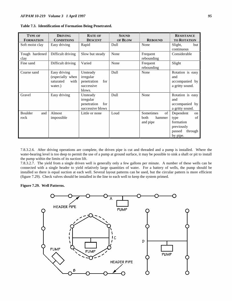
AFPAM 10-219 Volume 3 1 April 1997 95
Table 7.3. Identification of Formation Being Penetrated.
TYPE OF
FORMATION
DRIVING
CONDITIONS
RATE OF
DESCENT
SOUND
OF BLOW REBOUND
RESISTANCE
TO ROTATION
Soft moist clay Easy driving Rapid Dull None Slight, butcontinuous
Tough hardenedclay
Difficult driving Slow but steady None Frequentrebounding
Considerable
Fine sand Difficult driving Varied None Frequentrebounding
Slight
Coarse sand Easy driving(especially whensaturated withwater.)
Unsteadyirregularpenetration forsuccessiveblows.
Dull None Rotation is easyandaccompanied bya gritty sound.
Gravel Easy driving Unsteadyirregularpenetration forsuccessive blows
Dull None Rotation is easyandaccompanied bya gritty sound.
Boulder androck
Almostimpossible
Little or none Loud Sometimes ofboth hammerand pipe
Dependent ontype offormationpreviouslypassed throughby pipe.
7.8.3.2.6. After driving operations are complete, the driven pipe is cut and threaded and a pump is installed. Where thewater-bearing level is too deep to permit the use of a pump at ground surface, it may be possible to sink a shaft or pit to installthe pump within the limits of its suction lift.7.8.3.2.7. The yield from a single driven well is generally only a few gallons per minute. A number of these wells can beconnected with a single header to yield relatively large quantities of water. For a battery of wells, the pump should beinstalled so there is equal suction at each well. Several layout patterns can be used, but the circular pattern is more efficient(figure 7.29). Check valves should be installed in the line to each well to keep the system primed.
Figure 7.29. Well Patterns.

AFPAM 10-219 Volume 3 1 April 199796
7.8.3.3. Bored Wells. Bored wells are practical where ground water can be obtained at shallow depths and when only smallamounts of water are needed.7.8.3.3.1. Augers can be used to penetrate clay, silt, and those sands in which an open hole in the material will not cave in(figure 7.30). Holes of 25 to 50 feet are possible with diameters of 2 to 32 inches. Both hand and powered augers can beused, but powered augers--such as on the electrical line truck--are generally limited to a depth of about 10 feet. Duringboring, small rocks or boulders may be encountered. When this happens, replace the bit with a spiral or ram’s horn auger.The spiral will usually twist around the rock so that it can be lifted out. If this does not work, the hole will have to beabandoned.
Figure 7.30. Augers.
7.8.3.3.2. When boring deeper than 15 feet, a light tripod with a pulley at the top of a raised platform could be useful. Withthis, the longer auger rods can be inserted and removed from the hole without damage and without unscrewing the rodsections with each withdrawal.7.8.3.3.3. Hand augers can be modified to increase efficiency at greater depths by adapting ratchet and hold-down devices toincrease the rate of boring. Extensions to the auger handles allow people to apply greater pressure as the auger is rotated. Alarge ratchet wrench provides better leverage for turning the shaft which increases the rate of boring.7.8.3.3.4. When loose sand and gravel are encountered, progress in boring below the water table is often difficult orimpossible. This may be overcome by lowering a casing to the bottom of the hole and continuing to remove material whileforcing the casing down.7.8.3.3.5. Bored wells are completed by installing well screens in the water-bearing sand. If a standard well screen is notavailable, there are alternatives. Try a slotted PVC pipe with a cap on the end or a torch cut casing (figure 7.31). If a casinghad to be placed to control sand intrusion, lower the well string with the screen on the end to the bottom of the well on theinside of the casing. Then pull the casing back so the well screen is exposed to the sand layer. Fill the hole (annular space)around the well screen with gravel. Then fill the rest of the annular space around the pipe string or casing with soil. Cap t hewell with clay or some other impervious material if possible. This cap reduces contamination of the well. Thread the wellpipe and attach the pump. Just as with driven wells, multiple wells attached to a header may be required to yield a sufficientamount of water.

AFPAM 10-219 Volume 3 1 April 1997 97
Figure 7.31. Expedient Well Screens.
7.8.3.4. Jetted Wells. In the jetting method of well construction, a hole is drilled into the earth by the force of a highvelocity stream of water. This stream loosens the material it strikes and washes the fine particles upward out of the hole. Themethod is particularly successful in sand. It does not depend upon bulky drilling equipment which is difficult to transport. Itis simple, dependable and can be done with hand tools. Jetting also gives a capability to sink deeper wells. Four-inchdiameter pipes have been set to depths of 200 to 300 feet, and smaller diameters even deeper. Obviously, this permits tappingbetter ground water sources as long as a small diameter deep well pump is available. Jetting does have a drawback. Thedrilling operation needs a fair amount of water. In most cases water will not be plentiful for this is the reason construction ofa well is being considered in the first place. This situation will require a difficult command decision on how to use limitedavailable water resources. Where water sources are not located near the well site, water can be transported in waterdistributors, trailers or 55-gallon drums to support the jetting operation. When water for jetting is in short supply, an aircompressor can be used with the water to gain adequate pressure for jetting.7.8.3.4.1. Jetting Equipment (figure 7.32). The essential jetting equipment includes a hoist, a jetting pump with hose, andan adequate supply of jetting fluid--usually water. A hoist is needed to handle the drill pipe and casing. Hand-operatedequipment such as a tripod with tackle may be used. A pump with suitable hose connection and capable of delivering 50 to100 gallons per minute at a pressure of 50 psi is adequate. The volume is needed to keep the larger size soil particlessuspended as they are flushed up and out of the well hole. The pressure is needed to break up the compacted soil into smallparticles. Sandy soils require the most water, but high pressure is not necessary. Forty psi nozzle pressure is adequate inmost cases. Clay and hardpan require less water but they are not readily displaced except by a small cutting stream deliveredat high pressure. Pressure as high as 200 psi can be obtained from small nozzles. A 60 gpm pump should prove sufficient formost applications. Plain water is commonly used as a jetting fluid, but a fluid of greater viscosity may be prepared by mixingclay or a commercial bentonite with water. The heavier fluid tends to seal the wall of the hole and to prevent loss of waterinto the formation being penetrated. Jetting fluid is led from the hole to a settling pit where material washed up from the holesettles to the bottom. The fluid can then be picked up again by the jetting pump and recirculated. A nearby source of water isrequired to provide the initial and makeup water. With some equipment, a small drive weight is sometimes used. It ismanually dropped on the pipe to help the pipe penetrate clay or other semi-firm soils.

AFPAM 10-219 Volume 3 1 April 199798
Figure 7.32. Jetting Rig.
7.8.3.4.3. Setting Casing and Well Screen. A well hole can be formed large enough to set a casing and well screen. Whenthe jetting fluid prevents caving of the hole, the jetting pipe can be pulled and then the casing and screen can be inserted in asingle string. Otherwise, the casing must be sunk as fast as jetting proceeds. Figure 7.33 shows the details of an improvisedjetting device which permits sinking the casing during jetting. It can be used with water only or with an air-water mixture. Itis easily fabricated with simple pipe connections and includes a handle for applying downward pressure to aid in penetratingtightly compacted soils. Additional jetting pipe and casing can be easily added to the string. Figure 7.34 shows anotherimprovised jetting device. A string of pipe is equipped with a tight cap at the top and roughly cut teeth at the bottom. Four tosix teeth, 1-inch in length, are usually enough. The base of the teeth should be rounded so the teeth can more easily clearthemselves of gravel and other material. Half of the teeth should be bent outward so they cut a hole slightly larger than thecasing. If tight layers of silt and clay are encountered, the pipe is turned back and forth so the teeth break up the hardermaterial. To perform the jetting operation, attach the discharge hose from the pump to the connection provided in the top ofthe cap (figure 7.32). Suspend the casing vertically using the hoist. Permit the cutting head to rest on the ground, preferablyin a shallow hole dug by hand. At the start, almost the entire weight of the casing should rest on the ground. Operate thejetting pump at full capacity. The casing will fill with water and begin to sink by its own weight as the ground is washed outfrom under it. During drilling the hoist should keep enough tension on the casing to hold it vertical. It is important to drill astraight, vertical hole if a deep well pump with a shaft is to be used. Otherwise, the shaft can bind causing premature pumpfailure. If some resistance stops the downward movement, lift the casing 2 to 3 feet and drop it. Chain tongs or a largeratchet wrench can be used to rotate the tooth-casing to cut into the bottom of the hole. If more than one length of casing iswashed in, the well hole and the length of casing must be kept full of water at all times while the next length of pipe is beingattached. This maintains the fluid pressure against the hole wall and should prevent caving. When the casing reaches thedesired depth, telescope a well screen through the casing until it rests on the bottom of the well. Pull the casing up until thescreen is exposed to the water-bearing formation.
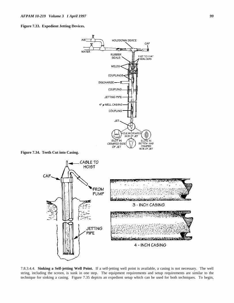
AFPAM 10-219 Volume 3 1 April 1997 99
Figure 7.33. Expedient Jetting Devices.
Figure 7.34. Teeth Cut into Casing.
7.8.3.4.4. Sinking a Self-jetting Well Point. If a self-jetting well point is available, a casing is not necessary. The wellstring, including the screen, is sunk in one step. The equipment requirements and setup requirements are similar to thetechnique for sinking a casing. Figure 7.35 depicts an expedient setup which can be used for both techniques. To begin,

AFPAM 10-219 Volume 3 1 April 1997100
attach the well point to the bottom of the well pipe and connect the discharge hose from the jetting pump to the other end ofthe first section of the well pipe. Upend the well point assembly and suspend it vertically by the hoist in a shallow dug hole.Start the pump and partially open the discharge valve. Again the soil is washed from under the well point allowing it to sinkinto the ground. Up-and-down movement of the well point assembly will speed penetration. As the jetting continues,increase the flow of water. In most sands, a pressure of 40 psi will readily displace the soil particles. Pressures of 100 to 150psi may be needed to move gravel or penetrate clay. If a regular jetting pump is not available, two standard centrifugal pumpsoperating in series may work satisfactorily. Continue until the well point has been sunk to the desired depth.
Figure 7.35. Expedient Setup for Jetting.
7.8.3.4.5. Determining Jetting Depth. As with all well drilling methods, a decision must be made when sufficientpenetration into a water-bearing strata has been reached. To help in this decision, take two actions. First, periodically checkthe returning drill fluid for amount and size of soil particles. This will indicate what type of soil is being drilled through.Then keep an eye on these indicators:7.8.3.4.5.1. Increased rate of penetration. The penetration rate may well increase as the jet point enters the saturated, lesscohesive sands and gravels.7.8.3.4.5.2. Amount of make-up water required increases significantly. This indicates loss of drilling fluid down the hole andthe well point may be in more porous material.7.8.3.4.5.3. Noticeable increase in the volume of returning drill fluid. This invariably means that an artesian aquifer has beenpenetrated.7.8.3.4.5.4. Complete loss of returning drill fluid. This means a very porous formation has been entered. If ground water ispresent, it is being pushed back by the drilling fluid.7.8.3.4.6. Completing the Jetted Well. To complete the jetted well, connect the well pipe with the suction end of the pump.The well will yield water immediately if the pump is in good condition and the well screen has been properly placed. Whenwater is obtained, it is a good practice to direct a stream of water into the hole around the well pipe. This washes soil into thehole. At first, a lot of sand will be drawn into the well screen and discharged with the water. This allows the coarse sand andgravel to pack solidly around the well screen and pipe, resulting in gradual clearing of the discharged water.7.8.3.5. Well Development. Although a well site may have been properly selected, the strata correctly interpreted, and thepresence of water accurately judged, a well may still fail to yield water at first since the sand around the well point is cloggedwith fine particles that need to be removed by development.

AFPAM 10-219 Volume 3 1 April 1997 101
7.8.3.5.1. Development is the process of causing the envelope of soil around the well screen to grade gradually from coarsestparticles next to the screen to unchanged natural formation at a distance outside the reach of the development method (figure7.36). Development disturbs the finer material next to the well point and then, by pumping the well, causes that material toflow into the well point where it is pumped to the surface. The well screen keeps the coarser particles outside where theyform an envelope of highly porous and permeable material around the screen. That envelope serves as a filter. It may beimpossible to develop a successful well if the screen openings are too fine. The screen openings must be large enough topermit the finer particles of soil to enter the well point while retaining the coarser particles.
Figure 7.36. Development of a Soil Formation.
7.8.3.5.2. The purpose of each development method is to induce alternate reversals of flow through the screen openings thatwill rearrange the formation particles, breaking down bridging of groups of small particles (figure 7.37). Proper developmentstabilizes the formation around the screen so the well water will remain sand free after it is completed. Although there areseveral methods to develop a well, few are of an expedient nature. One, however, a surging technique, can be used asfollows:

AFPAM 10-219 Volume 3 1 April 1997102
Figure 7.37. Bridging of Sand Grains.
7.8.3.5.2.1. With the well pump installed, pump the well until water starts to flow. Stop the pumping, allowing air into thepipe, so the water will rapidly flow back down the well pipe. As the water flows back, it backwashes the screen and disturbsthe soil outside the screen. The pump is restarted until the well water again reaches the surface. This process is repeatedmany times. The fine material sucked into the screen is then pumped from the well with a continuous hard pumping for a fewminutes. Continue development until the water clarity is acceptable for treatment. If sediment cannot be cleared from ashallow well by pumping, try one of these techniques (if the well is not deeper than 15-20 feet).7.8.3.5.2.1.1. Lower a series of connected lengths of 3/4-inch pipe into the well with the lower end resting on the sediment inthe well point. Clamp the pipe in position and attach a hand pump to the upper end. Run water into the well pipe--not the3/4-inch pipe--and operate the hand pump. By pumping steadily, the sediment will be lifted through the 3/4-inch pipe.Continue to lower the 3/4-inch pipe to the sediment level until the well is cleared.7.8.3.5.2.1.2. Insert a string of 3/4-inch pipe into the well and fill the well with water. Repeatedly raise and lower the pipesharply by hand. By holding your thumb over the top of the 3/4-inch pipe during the upward movement and removing thethumb during the downward movements, a jet of muddy water is expelled on each downward stroke. When the material hasbeen loosened and put into suspension, the muddy water can be pumped out.
7.9. Expedient Facility Repairs. Few personnel have experienced a situation where massive facility damage has occurred.A natural disaster such as a hurricane or tornado can produce sizable facility damage and destruction, but probably not to theextent of an air attack in wartime. In a wartime environment you will face, in addition to facility damage, the prospect ofhaving to contend with multiple fires, unexploded ordnance, wide spread debris, injured personnel, and possibly evenchemical agent presence. All these factors complicate response to facility repair. It is difficult to accurately determine thedegree of facility damage that could be encountered since there are many variables that could influence the outcome. Some ofthese include type of ordnance used, targets chosen for attack, type of facility construction, degree of hardening employed,and numbers of aircraft or missiles used. You can expect, however, damage ranging from light such as window breakage toheavy such as total facility destruction, with many shades in between. Computer simulations of various attack scenarios uponan air base have given an indication of the probable extent of damage that could be incurred. One such simulation depictedthe damage shown in table 7.4. While it may not look staggering at first, keep in mind that an engineer squadron will beaccomplishing runway, utility, and these facility repairs almost simultaneously; therefore, only a fraction of the unit will bededicated to the facility repair task. Additionally, the numbers shown are averages. In some of the attack iterations thenumbers were two to three times greater than what is shown. When the numbers triple, a real challenge is presented.

AFPAM 10-219 Volume 3 1 April 1997 103
Table 7.4. Potential Wartime Facility Damage.
TYPE OCCURRENCES
Roof/Wall CollapseRoof/Wall Breach
Window/Door Frame DamageWindow Breakage
6111430
7.9.1. Damage Assessment and Prioritization. Because a multitude of facility repair requirements will be faced and onlylimited manpower and material resources will probably be available, some sort of an assessment and prioritization processwill have to be applied. As mentioned earlier, assessments are performed by DARTs which investigate the extent of utilityand facility damages after an attack. Included in their assessment are estimates of manpower and material requirementsneeded to make repairs. As damage reports are received from the DARTs, the damage control center will decide thesequencing of repair activities based on previously developed contingency response plans, available material and personnelresources, and the extent and type of damage actually existing in the field. Once repair requirements are determined, repaircrews will be dispatched. Keep in mind that only expedient repairs are to be accomplished; if repair crews find conditions aremuch worse than what was reported by the DARTs, the crews must notify the DCC of the situation so a go/no go decision canbe made with respect to continuing with the repair. From a structural perspective the following facility repair priorities can beexpected to be the most common:• Navigation aids.• Command posts and similar command and control facilities.• Communications facilities.• POL/Munitions facilities.• Fire station.• Medical facilities.7.9.2. Facility Repair Considerations. Expedient repair of facilities must be viewed from a common sense perspective.The following considerations should form the basis for post attack facility repair activities.7.9.2.1. Safety is Paramount. The wartime environment is hazardous enough without endangering personnel through unsafeacts during repair activities. Structures may be weakened, live electrical wires may be down, explosive gas vapors may bepresent, chemical or biological contamination may be prevalent, and unexploded ordnance may litter the base. Air basemedical facilities will be crowed with casualties and civil engineer manpower will be at critical levels. These conditions willmake it essential that resources are not further taxed by injuries caused through neglect of safety practices. Enthusiasm forgetting the job done must be tempered with prudent assessment of the risks being confronted. Time should be taken to make apreliminary survey of any suspect structures before any repairs are attempted.7.9.2.2. Expediency is Key. All engineer efforts immediately following an emergency should be limited to minimumessential repair of crucial facilities. Work performed should concentrate on functional rather than cosmetic repair. Allstructural repair efforts should be geared toward making a facility safe for occupancy and providing minimal protection fromthe elements to persons using the facility.7.9.2.3. Mission Comes First. The importance of the facility to the overall base mission determines the priority of repair thefacility receives. Those damaged activities which are not essential to the base mission and do not present a hazard should beleft as they are until time and resources permit conventional repairs.7.9.2.4. Practicality is Necessary. Considerations of other related repair activities affecting the facility should be taken intoaccount. For example, if the facility provides service to aircraft and all access pavements are so severely damaged that theycannot be made usable for days, the structural repair can wait. Similarly, if the supporting utility systems to a facility are farbeyond emergency repair, the structural portion of the repair effort can be delayed. On the other hand, lack of full utilityservice does not mean a building will be totally useless. Partial utility service, for example, electrical but no water, can stillmean a facility can be used for its wartime purpose. The DCC will have to make the decision as to the practicality of repair.7.9.2.5. Flexibility is Important. Priorities will change and engineer efforts must follow. No two attacks will be identical;therefore, no two sets of structural repair taskings will be identical. Engineer forces must not get locked into a standard set offacility priorities and spend a lot of time on minor repairs to them to the detriment of other facilities on base. It could justhappen that emergency repairs to the base power plant could be more important at some point in time than minor repairs tothe wing command post.7.9.3. Expedient Structural Repair Methods. The first concern in structural repairs should be shoring any weakened areasto restore a minimum degree of structural integrity to the facility. In wartime or immediately after a natural disaster there isnot time to make a detailed engineering analysis on structural soundness. You will have to rely on field experience, facility
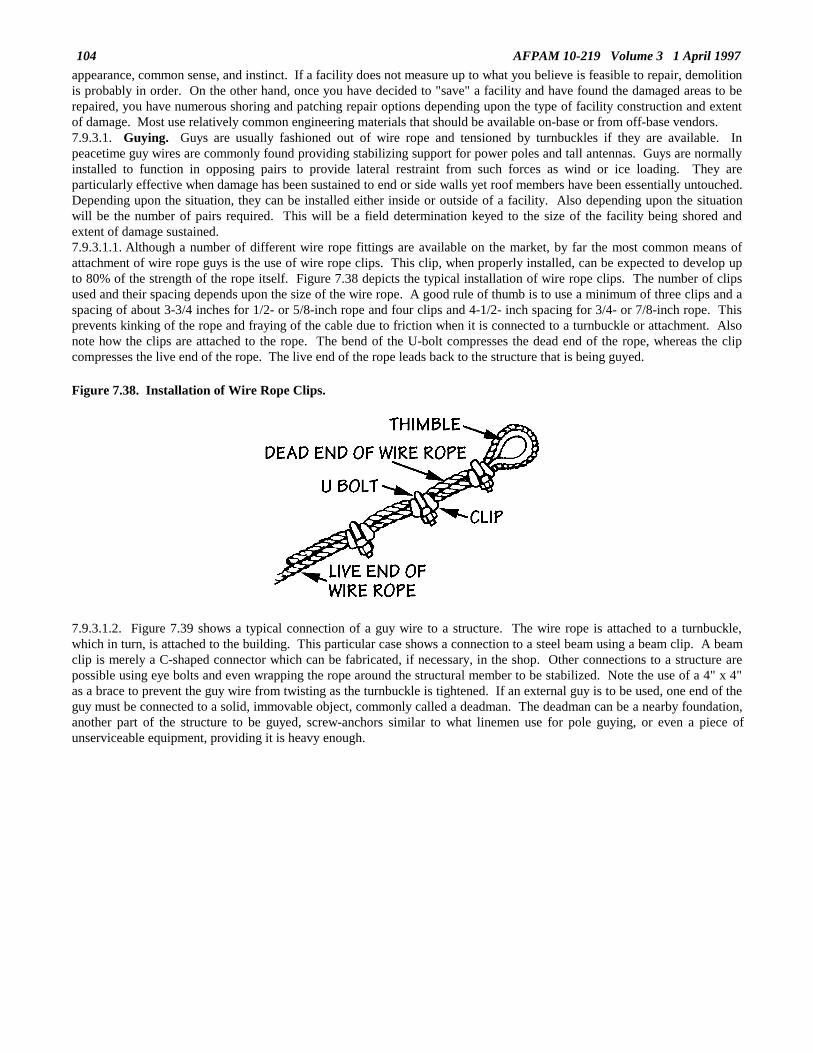
AFPAM 10-219 Volume 3 1 April 1997104
appearance, common sense, and instinct. If a facility does not measure up to what you believe is feasible to repair, demolitionis probably in order. On the other hand, once you have decided to "save" a facility and have found the damaged areas to berepaired, you have numerous shoring and patching repair options depending upon the type of facility construction and extentof damage. Most use relatively common engineering materials that should be available on-base or from off-base vendors.7.9.3.1. Guying. Guys are usually fashioned out of wire rope and tensioned by turnbuckles if they are available. Inpeacetime guy wires are commonly found providing stabilizing support for power poles and tall antennas. Guys are normallyinstalled to function in opposing pairs to provide lateral restraint from such forces as wind or ice loading. They areparticularly effective when damage has been sustained to end or side walls yet roof members have been essentially untouched.Depending upon the situation, they can be installed either inside or outside of a facility. Also depending upon the situationwill be the number of pairs required. This will be a field determination keyed to the size of the facility being shored andextent of damage sustained.7.9.3.1.1. Although a number of different wire rope fittings are available on the market, by far the most common means ofattachment of wire rope guys is the use of wire rope clips. This clip, when properly installed, can be expected to develop upto 80% of the strength of the rope itself. Figure 7.38 depicts the typical installation of wire rope clips. The number of clipsused and their spacing depends upon the size of the wire rope. A good rule of thumb is to use a minimum of three clips and aspacing of about 3-3/4 inches for 1/2- or 5/8-inch rope and four clips and 4-1/2- inch spacing for 3/4- or 7/8-inch rope. Thisprevents kinking of the rope and fraying of the cable due to friction when it is connected to a turnbuckle or attachment. Alsonote how the clips are attached to the rope. The bend of the U-bolt compresses the dead end of the rope, whereas the clipcompresses the live end of the rope. The live end of the rope leads back to the structure that is being guyed. Figure 7.38. Installation of Wire Rope Clips.
7.9.3.1.2. Figure 7.39 shows a typical connection of a guy wire to a structure. The wire rope is attached to a turnbuckle,which in turn, is attached to the building. This particular case shows a connection to a steel beam using a beam clip. A beamclip is merely a C-shaped connector which can be fabricated, if necessary, in the shop. Other connections to a structure arepossible using eye bolts and even wrapping the rope around the structural member to be stabilized. Note the use of a 4" x 4"as a brace to prevent the guy wire from twisting as the turnbuckle is tightened. If an external guy is to be used, one end of theguy must be connected to a solid, immovable object, commonly called a deadman. The deadman can be a nearby foundation,another part of the structure to be guyed, screw-anchors similar to what linemen use for pole guying, or even a piece ofunserviceable equipment, providing it is heavy enough.

AFPAM 10-219 Volume 3 1 April 1997 105
Figure 7.39. Guy Wire Connection.
7.9.3.1.3. As mentioned earlier, guys can be installed either internally or externally. Figure 7.40 illustrates the internalconfiguration. They must be tightened in pairs. The guys should be tightened concurrently to avoid placing too much stresson the structure’s frame at any particular point. Do not overtighten, however. You basically just want to take all the sag outof the ropes.
Figure 7.40. Internal Guy System.
7.9.3.1.4. The external guy configuration is also installed in pairs (figure 7.41). The main difference is instead of using thestructure itself as the end points for the guys, external anchors or deadmen, are used. The stabilization effect is essentially thesame, however.

AFPAM 10-219 Volume 3 1 April 1997106
Figure 7.41 External Guy System.
7.9.3.2. Bracing. Braces are compression members usually made of structural-steel and heavy timbers (figure 7.42). Likeguys, they can be installed either internally or externally. Sometimes they are placed in opposite pairs; other times they areused singly. Care must be taken when installing bracing on a facility that adequate connections to the facility are made. If thebracing is not well attached, the probability is great that it will slide out of position and the facility will suffer further damagesor perhaps collapse. Footings for bracing have the same problem. They must be of sufficient mass so as not to be movedwhen force is applied. You cannot just shove the brace into the ground and expect it to hold. If another part of the structure’sfoundation or the foundation of an adjacent building is not available, you may have to build an expedient footing out ofrubble, sheet metal, or timber.
Figure 7.42. Typical Brace.
7.9.3.2.1. In most cases you will have to install braces in pairs as shown in figure 7.43. Like guy wires, more than one pair ofbraces may be required for a facility. This will be an on-site decision, generally driven by the size of the building beingshored and severity of damage.

AFPAM 10-219 Volume 3 1 April 1997 107
Figure 7.43. Externally Opposed Braces.
7.9.3.2.2. Internal braces are depicted in figure 7.44. They are likewise normally installed in pairs. Keep in mind that bracesmust be firmly attached to the facility so they do not slip out of position when pressure is applied.
Figure 7.44. Internally Opposed Braces.
7.9.3.3. Jacking. Guying and bracing usually are used to stabilize a facility from lateral movement, that is, keeping abuilding from moving side to side. In some cases, the structural integrity of a facility may be jeopardized due to damagedstructural members that are more directly affected by vertical loads; that is, the effects of gravity. In such situations you willoften see deflected or cracked beams or girders which need vertical support or damaged columns that will eventually needreplacement. The use of shoring jacks helps solve these types of problems expediently.7.9.3.3.1. Shoring jacks are placed immediately under the point of deflection or adjacent to the damaged column andextended until they are firmly wedged into position (figure 7.45). Any debris around the base of the jacks must be clearedaway so that the jacks are squarely on the facility floor. While not shown in the figure, it is also advisable to brace the jacksonce they are in position. This can be accomplished by welding two steel plates on the jacks at 90 degrees to each other. Theplates should have 3/4-inch holes drilled in them. Standard 2" x 4"s are then bolted to the plates at one end and nailed at theother end to short pieces of 2" x 4" stock which have been attached to the floor of the facility using a ramset.

AFPAM 10-219 Volume 3 1 April 1997108
Figure 7.45. Shoring Jack Installation.
7.9.3.3.2. In most cases shoring jacks will be in short supply and too valuable to leave in place in damaged facilities. Analternative to leaving the jacks is using timbers as supporting members (figure 7.46). Wood and timber are extensively usedto shore damaged structural components because of their availability and economy. A variety of elements can be usedranging from tree logs, sawn timbers and utility poles to industrially made items with different cross sections such as planks,boards and beams. The procedures for installing timbers are similar to using jacks but will tend to be a bit more manpowerintensive. After clearing debris away from the work area, a shoring jack is placed immediately adjacent to the location wherethe timber is going to go. The jack is then raised until its capacity is reached or it can no longer be extended, whichevercomes first. The distance from the top of the jack to the floor is measured and the timber is cut a 1/2-inch shorter than thismeasurement. Once cut, the timber is raised into position and several wedges are pounded into the 1/2-inch gap between thetop of the timber and the damaged beam, thus securing the timber into position. The shoring jack is then lowered andremoved. The final step is to brace the timber in two directions similar to what was done earlier with nails, ramset and 2" x 4"stock.

AFPAM 10-219 Volume 3 1 April 1997 109
Figure 7.46. Timber Column.
7.9.3.3.3. Timber shoring can also be used for expedient repair of damaged load bearing walls with openings such aswindows or doors. The use of timber to take the vertical load from a damaged masonry pier between two windows is shownin figure 7.47. Note that bracing has been used between the vertical timbers in each window opening. This commonconstruction technique increases the efficiency of the timbers by reducing their potential for buckling under any increases inload. Also note that spreader beams have been placed at the top and bottom of the timbers where they meet the windowframes. These beams spread the vertical load over a larger surface area decreasing the chance of punching through orshearing the window frame. Spreader beams can be made from planks, boards or even steel plates. The wedges shown infigure 7.47 are used to secure the vertical timbers in position. One final note concerning the use of timbers. As you know,heavy timbers are not particularly common at an air base; therefore, you must be resourceful. Other facilities on the base thathave been damaged beyond repair may contain salvageable timbers or you may have to consider nailing, gluing, bolting, orbanding 2" x 8" or 2" x 10" stock together to form usable substitutes.
Figure 7.47. Support of Damaged Load Bearing Walls with Openings.

AFPAM 10-219 Volume 3 1 April 1997110
7.9.3.4. Splinting. Another method of providing basic structural integrity involves the splinting of columns, particularly thereinforced concrete type, that have not been seriously damaged, yet show signs of cracking or minor fracture.7.9.3.4.1. One technique involves the "sandwiching" of the damaged column between two steel plates connected by threadedrods. The plates have slotted holes in them so they can be fitted to various sized columns. In this repair, a splint is placedaround a cracked column at the location of the crack(s) to provide a lateral restraining force and keep the column fromslipping along the crack’s face (figure 7.48). If cracks are at several locations on the column, multiple splints can be used.This repair is preferable to column replacement when a damaged column is still capable of carrying a significant load,because it requires less manpower and is a faster repair. However, if a column is severely damaged, so it appears to be nearthe point of collapse, column replacement using jacks or timber supports should be used.
Figure 7.48. Steel Plate Splint.
7.9.3.4.2. A second splinting technique involves placing angle iron at the corners of a damaged column and connecting theangles with steel straps (figure 7.49). Steel plates should be provided at the ends of the angles to avoid load bearing problemsat the bottom of the column where it is attached to the slab.
Figure 7.49. Use of Steel Angles at Corners of a Damaged Column.
7.9.3.4.3. A third method of splinting again uses angle iron at the corners at the damaged column, however, they are joinedtogether with wire rope or similar cabling (figure 7.50). One end of the wire rope is welded to the top of one of the anglesand then the rope is tightly wound around the column. At the base of the column the other end of the wire rope is welded toone of the angles. If time permits, additional welds may be made at various points to better secure the cable to the angle iron.

AFPAM 10-219 Volume 3 1 April 1997 111
Figure 7.50. Use of Wound Spiral to Repair Column.
7.9.3.5. Tension Ties. You may run across some facilities at overseas locations that are essentially all reinforced concreteconstruction. In such cases, slabs and beams will be of unitary construction, that is, formed, reinforced, and poured as asingle unit. After an attack you may find that some of the slabs and beams may have developed minor cracking. Tension tiesare a method of providing a compressive force on the slabs and beams which aids in the prevention of further cracking (figure7.51). For slab repair a threaded rod is anchored to the beams on both sides of the cracked area of the slab. For beams,anchor plates are bolted to the beam on both sides of the crack and a threaded rod is placed parallel to the beam connectingthe two anchor plates. Tightening of the nuts on the threaded rod induces a compressive force into the beam or slab therebyrestricting further cracking.
Figure 7.51. Tension Ties.
7.9.3.6. "Stitching Dogs." Another method of restoring some structural integrity into a cracked concrete slab is the use of"stitching dogs". These "dogs" are steel bars, normally rebar, formed into a U-shape and placed over the crack sort of likestaples (figure 7.52). The "dogs" should be of random length and variably spaced along the crack. The holes the "dogs" areinserted into must be well grouted to ensure a tight fit.

AFPAM 10-219 Volume 3 1 April 1997112
Figure 7.52. "Stitching Dogs."
7.9.3.7. Welding. The last method to be discussed deals with shoring techniques you are familiar with--welding steelsections back into place to restore the stability of a steel framework. Efforts in this area will usually be limited to repairing arelatively small section of a facility. To attempt more than this as an expedient repair will quickly add up to too much in theway of time and manhours. For the most part, such repairs will involve clearing debris and disfigured structural membersfrom the work area, erecting scaffolding, positioning steel plate and structural shapes, and accomplishing the welding.7.9.4. Weather Protection. Once basic structural integrity has been restored, steps can be taken to protect personnel andessential equipment from the elements. This protection is usually afforded by patching holes in walls, roofs, and floors.Before expending resources to patch these holes, determine if urgent, immediate patching is required. Local climate andprevailing weather are major factors. If the weather is warm and rainfall is not a detrimental factor, some areas may be leftexposed temporarily without significant impact on the mission. On the other hand, if patching is required, there are severaldifferent types of materials and techniques that can be used.7.9.4.1. Roof Repairs. From an expedient aspect it will be difficult to completely seal off the building from weather, butmost of the ill effects of bad weather can be kept out. If supporting roof trusses are basically in-place, sheets of plywood canbe nailed over the opening (figure 7.53). Sheet metal, plastic sheeting, and even canvas can be used in lieu of plywood. If theroof trusses have sustained only minor damage, bracing and supports could be added before the plywood or other cover isinstalled. For flat roofs, sheets of plywood can be fabricated into a patch a bit larger than the hole and nailed in place. If theroof is concrete, a ramset could be used to attach the plywood patch. For larger patches internal supports may be needed.Vertical bracing in the form of 4" x 4"s can be cut to fit and nailed at one end to the patch and at the other end to 2" x 4" stockattached to the floor using the ramset. If available, rolled roofing can then be nailed to the patch for added weatherprotection.

AFPAM 10-219 Volume 3 1 April 1997 113
Figure 7.53. Plywood Roof Repair.
7.9.4.2.. Wall Repairs. For the most part, wall repairs are similar to roof repairs except they should be somewhat easiersince the requirement to lift all materials to roof height is eliminated. Damage to walls can be covered with standard materialssuch as plywood, sheet metal, and sheeting (figure 7.54). If the wall damage is near the ground level and the structure isstrong enough to support it, earth can even be bermed against the facility for added protection from possible future attacks. Ifnormal construction materials run low, many alternatives may be available. A few examples are lumber from packing cratesand shipping dunnage, revetment bin material, AM-2 matting, salvaged debris and cannibalized materials from other facilities,and RRR concrete slabs (figure 7.55).
Figure 7.54. Plywood Wall Repair.
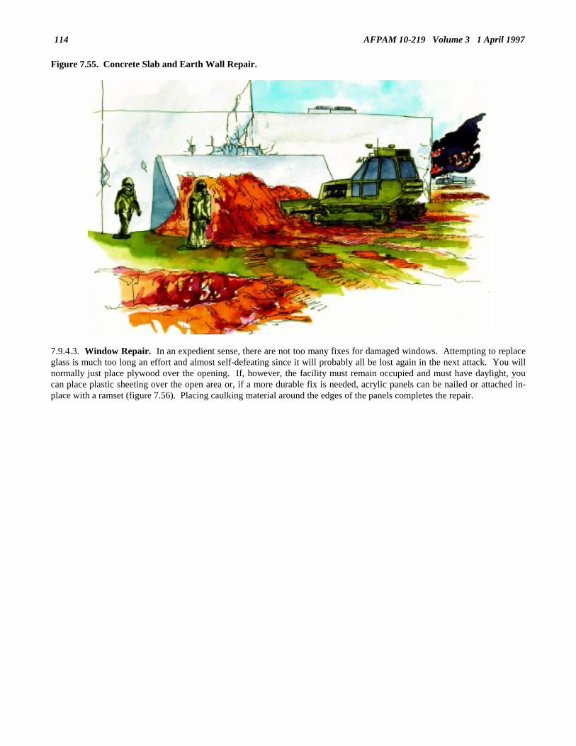
AFPAM 10-219 Volume 3 1 April 1997114
Figure 7.55. Concrete Slab and Earth Wall Repair.
7.9.4.3. Window Repair. In an expedient sense, there are not too many fixes for damaged windows. Attempting to replaceglass is much too long an effort and almost self-defeating since it will probably all be lost again in the next attack. You willnormally just place plywood over the opening. If, however, the facility must remain occupied and must have daylight, youcan place plastic sheeting over the open area or, if a more durable fix is needed, acrylic panels can be nailed or attached in-place with a ramset (figure 7.56). Placing caulking material around the edges of the panels completes the repair.

AFPAM 10-219 Volume 3 1 April 1997 115
Figure 7.56. Window Repair.
7.9.5. Utility Support. Although expedient utility repairs were covered in a previous section, certain aspects of utilityservice must be considered in structural repairs. First, the feasibility of making structural repairs to a facility is sometimesdetermined by the status of a given utility system. For example, it would not be logical to make structural repairs to thecommand post if restoration of electrical and communications services is impossible. However, do not assume that justbecause all utilities cannot be restored at once, the structure is of no use. If one or more critical utilities can be repaired, theabsence of other, less critical utilities may not impair mission accomplishment. To illustrate, if the electrical service to a vitalcommand and control facility could be restored, allowing operation of electronic equipment, the lack of water and sewagedisposal should not be seen as a limiting factor for continued use of the structure. Water could be brought to the site inportable containers and an expedient field sanitation facility could satisfy human waste disposal needs. Another importantconsideration during structural repairs is accommodations for utilities repairs. If makeshift utility repairs have already beenmade, structural repair teams should exercise care in their work to prevent disruption of service. If utility repairs have yet tobe made, structural repair teams may be able to modify the structure during their restoration efforts to facilitate the repair ofservicing utilities.7.9.6. Conversion of Alternate Facilities. Depending on the type emergency that the base has encountered, there may besome facilities which are damaged beyond expedient repair capabilities. If such a facility is vital to the air base mission,another facility must be converted to meet the uninhabitable facility’s role. To effectively convert another facility, the BCEmust understand the function of the destroyed structure. Equipped with this knowledge, potential alternate facilities can beevaluated in terms of size, utilities support, and other special functional requirements. To select or recommend the bestfacility for conversion, the BCE should consider two factors. First, what other structures on the base come closest to meetingthe requirements for an alternate facility? Second, how much work will be required to convert the facility for its intendeduse? If there are no special considerations, the structure meeting the functional requirements and taking the least amount oftime to convert should be selected.
7.10. Debris Removal. A major disaster or enemy attack will generate vast amounts of debris, obstructing runways,taxiways, and other pavement areas. Base streets may be blocked by fallen trees or parts of damaged structures. Importantbase facilities and utility distribution systems may be inaccessible due to an accumulation of debris. If the base is to regainsome degree of its mission capability, these obstacles must be removed. This section will cover debris removal for areas ofthe base other than runways and aircraft operating surfaces. Debris removal from these pavement areas is discussed involume 4 of this publication series.7.10.1. Safety. Safety continues to be a primary concern in this area of base recovery. Removing large pieces of debris,
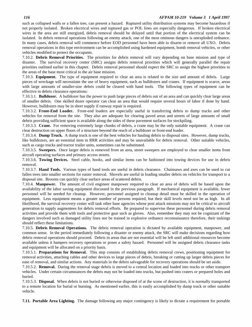
AFPAM 10-219 Volume 3 1 April 1997116
such as collapsed walls or a fallen tree, can present a hazard. Ruptured utility distribution systems may become hazardous ifnot properly isolated. Broken electrical wires and ruptured gas or POL lines are especially dangerous. If broken electricalwires in the area are still energized, debris removal should be delayed until that portion of the electrical system can beisolated. In debris removal operations following an enemy attack, one of the most ominous dangers is unexploded ordnance.In many cases, debris removal will commence before EOD personnel have been able to disarm or remove all UXO. Debrisremoval operations in this type environment can be accomplished using hardened equipment, bomb removal vehicles, or othervehicles modified to protect the occupants.7.10.2. Debris Removal Priorities. The priorities for debris removal will vary depending on base mission and type ofdisaster. The survival recovery center (SRC) assigns debris removal priorities which will generally parallel the repairpriorities outlined earlier in this chapter. Debris removal personnel should expect the SRC to assign the highest priorities tothe areas of the base most critical to the air base mission.7.10.3. Equipment. The type of equipment required to clear an area is related to the size and amount of debris. Largepieces of wreckage will necessitate the use of heavy equipment, such as bulldozers and cranes. If equipment is scarce, areaswith large amounts of smaller-size debris could be cleared with hand tools. The following types of equipment can beeffective in debris clearance operations:7.10.3.1. Bulldozer. A bulldozer has the power to push large pieces of debris out of an area and can quickly clear large areasof smaller debris. One skilled dozer operator can clear an area that would require several hours of labor if done by hand.However, bulldozers may be in short supply if runway repair is required.7.10.3.2. Front-End Loader. Front-end loaders are especially useful in transferring debris to dump trucks and othervehicles for removal from the site. They also are adequate for clearing paved areas and streets of large amounts of smalldebris providing sufficient space is available along the sides of these pavement surfaces for stockpiling.7.10.3.3. Crane. For removing extremely large chunks of debris, a crane may be the only suitable equipment. A crane canclear destruction on upper floors of a structure beyond the reach of a bulldozer or front-end loader.7.10.3.4. Dump Truck. A dump truck is one of the best vehicles for hauling debris to disposal sites. However, dump trucks,like bulldozers, are an essential item in RRR activities and may be unavailable for debris removal. Other suitable vehicles,such as cargo trucks and tractor trailer units, sometimes can be substituted.7.10.3.5. Sweepers. Once larger debris is removed from an area, street sweepers are employed to clear smaller items fromaircraft operating surfaces and primary access streets.7.10.3.6. Towing Devices. Steel cable, hooks, and similar items can be fashioned into towing devices for use in debrisremoval.7.10.3.7. Hand Tools. Various types of hand tools are useful in debris clearance. Chainsaws and axes can be used to cutfallen trees into smaller sections for easier removal. Shovels are useful in loading smaller debris on vehicles for transport to adisposal site. Brooms can quickly clear surface areas of scattered debris.7.10.4. Manpower. The amount of civil engineer manpower required to clear an area of debris will be based upon theavailability of the labor saving equipment discussed in the previous paragraph. If mechanical equipment is available, fewerpersonnel will be needed for cleanup. However, personnel assigned to cleanup detail must be skilled in the operation ofequipment. Less equipment means a greater number of persons required, but their skill levels need not be as high. In alllikelihood, the survival recovery center will task other base agencies whose post attack missions may not be critical to aircraftgeneration to supply augmentees for debris removal efforts. Be prepared to supervise these personnel during debris removalactivities and provide them with tools and protective gear such as gloves. Also, remember they may not be cognizant of thedangers involved such as damaged utility lines nor be trained in explosive ordnance reconnaissance therefore, their taskingsshould reflect these limitations.7.10.5. Debris Removal Operations. The debris removal operation is dictated by available equipment, manpower, andcommon sense. In the period immediately following a disaster or enemy attack, the SRC will make decisions regarding howdebris removal operations should proceed. Debris in areas that are not essential will be left until additional resources becomeavailable unless it hampers recovery operations or poses a safety hazard. Personnel will be assigned debris clearance tasksand equipment will be allocated on a priority basis.7.10.5.1. Preparations for Removal. This step consists of establishing debris removal crews, positioning equipment forremoval activities, attaching cables and other devices to large pieces of debris, breaking or cutting up larger debris pieces forease of removal, and similar actions. Any materials in the debris salvageable for recovery operations should be set aside.7.10.5.2. Removal. During the removal stage debris is moved to a central location and loaded into trucks or other transportvehicles. Under certain circumstances the debris may not be loaded into trucks, but pushed into craters or prepared holes andburied.7.10.5.3. Disposal. When debris is not buried or otherwise disposed of at the scene of destruction, it is normally transportedto a remote location for burial or burning. As mentioned earlier, this is easily accomplished by dump truck or other suitablevehicle.
7.11. Portable Area Lighting. The damage following any major contingency is likely to dictate a requirement for portable
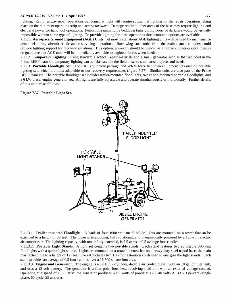
AFPAM 10-219 Volume 3 1 April 1997 117
lighting. Rapid runway repair operations performed at night will require substantial lighting for the repair operations takingplace on the minimum operating strip and access taxiways. Damage repair to other areas of the base may require lighting andelectrical power for hand tool operations. Performing many force beddown tasks during hours of darkness would be virtuallyimpossible without some type of lighting. To provide lighting for these operations three common options are available.7.11.1. Aerospace Ground Equipment (AGE) Units. At most installations AGE lighting units will be used by maintenancepersonnel during aircraft repair and reservicing operations. Borrowing such units from the maintenance complex couldprovide lighting support for recovery situations. This option, however, should be viewed as a fallback position since there isno guarantee that AGE units will be immediately available to engineer forces when needed.7.11.2. Temporary Lighting. Using standard electrical repair materials and a small generator such as that included in thePrime BEEF team kit, temporary lighting can be fabricated in the field to serve small area projects and needs.7.11.3. Portable Floodlight Set. The RRR equipment package and WRM force beddown equipment sets include portablelighting sets which are most adaptable to our recovery requirements (figure 7.57). Similar units are also part of the PrimeBEEF team kit. The portable floodlight set includes trailer-mounted floodlights, two tripod-mounted portable floodlights, anda 6 kW diesel engine generator set. All lights are fully adjustable and operate simultaneously or individually. Further detailsof this unit are as follows:
Figure 7.57. Portable Light Set.
7.11.3.1. Trailer-mounted Floodlight. A bank of four 1000-watt metal halide lights are mounted on a tower that an beextended to a height of 30 feet. The tower is telescoping, fully rotational, and pneumatically powered by a 120-volt electricair compressor. The lighting capacity, with tower fully extended, is 7.5 acres at 0.5 average foot-candles.7.11.3.2. Portable Light Stands. A light set contains two portable stands. Each stand features two adjustable 500-wattfloodlights with a quartz light source. Lights are mounted on a rotatable cross bar on a heavy duty steel tripod base, the mainmast extendible to a height of 12 feet. The set includes two 150-foot extension cords used to energize the light stands. Eachstand provides an average of 0.5 foot-candles over a 16,500 square foot area.7.11.3.3. Engine and Generator. The engine is a 12 HP, 2-cylinder, 4-cycle air cooled diesel, with an 18 gallon fuel tank,and uses a 12-volt battery. The generator is a four pole, brushless, revolving field unit with an external voltage control.Operating at a speed of 1800 RPM, the generator produces 6000 watts of power at 120/240 volts AC (+/- 3 percent) singlephase, 60 cycle, 25 amperes.

AFPAM 10-219 Volume 3 1 April 1997118
7.11.3.4. Trailer. The single axle trailer is designed to hold all components, including portable stands and all light fixtures.The frame is made from heavy-duty welded tubular steel and there are four retractable swivel pad leveling jacks withextendible outriggers. In the towing mode the unit is 67 inches high, 71 inches wide, and 127 inches long. Fully packed, theset weighs 2260 pounds.
7.12. Summary.7.12.1. Expedient methods will be required to repair air base damage resulting from a natural disaster or enemy attack.Considerations include extent of damage, principles of repair, and priorities of repair following an emergency condition. AirForce engineers have the responsibility for emergency repairs using expedient methods on USAF installations. The U. S.Army has responsibility for major restoration and emergency repairs beyond Air Force organic capability. In this regard,however, U. S. Army forces may not be immediately available; therefore, the BCE must plan accordingly. The CONUS andtheater expedient repair techniques may differ substantially due to the local environment, availability of resources, and thetype of systems needing repair.7.12.2. If expedient repairs are to be accomplished in a timely manner following a catastrophe, it is important that therecovery effort be well organized and coordinated. Starting with initial damage assessment, all activities are structured toreflect the existing situation. The damage assessment and response teams are manned with personnel having experience in themajor structural and utility related engineering trades and are instructed on the type of information needed for repair planningand response. The DCC uses the damage assessment inputs from the assessment teams to build a base recovery strategy. Asdamaged areas are identified, expedient repair efforts are organized to restore vital base infrastructure. Repairs areconcentrated on three major areas: runway ancillary equipment, crucial base utility systems, and key base structures.7.12.2.1. Runway ancillary equipment includes aircraft arresting barriers, airfield lighting, navigation aids, and supportingutilities. These systems are critical to the launch and recovery of combat aircraft and therefore receive high priority for repairefforts.7.12.2.2. Base utility systems include electrical, water, POL, natural gas, HVAC, sewer, and drainage. Expedient repairs tothese systems generally include isolation of the systems or quick fixes such as clamps and splices but in some cases, a newsource of the utility must also be provided. Installation of mobile generators and construction of shallow wells with theaccompanying water treatment equipment support may be necessary.7.12.2.3. Expedient repair of mission critical structures is generally limited to shoring and patching activities. In somesituations, however, demolition is required to eliminate major safety hazards.7.12.3. Expedient repairs are generally considered complete when major damage has been eliminated and most systems arecapable of performing their basic function. Civil engineer forces now turn their efforts to a more permanent upgrade of thesemakeshift remedies and the organization of resources for the continuing operations and maintenance required to sustain the airbase mission.

AFPAM 10-219 Volume 3 1 April 1997 119
Chapter 8
AIRCRAFT ARRESTING SYSTEMS
8.1. Introduction. Volume 4 of this publication series addresses selection, expedient repair, and marking of a minimumoperating strip (MOS) for launch and recovery of aircraft following an enemy attack. If the selected MOS is to support combataircraft operations, an effective arresting system must be in operation for the possible engagement of high speed fightersreturning to the base with battle damage and other emergencies. Additionally, for those occasions when a short MOS isemployed or weather conditions are expected to be poor during aircraft recovery operations, an arresting system will be neededeven for routine aircraft recovery operations.
8.2. Overview. This chapter discusses aircraft arresting systems which are capable of being relocated from storage or areas ofexpedient installation to another point of employment. The two primary types of systems considered are: mobile andexpeditionary systems. The mobile system detailed in this publication is the mobile aircraft arresting system (MAAS) (figure8.1) and its applications in a contingency environment will be discussed. The final section of the chapter addresses the BAK-12system as employed in the expeditionary configuration.
Figure 8.1. Mobile Aircraft Arresting Barrier.
8.3. Mobile Aircraft Arresting System (MAAS). The primary purpose of the MAAS is to provide rapid deployment of anaircraft recovery capability, enabling high cycle arrestment of hook-equipped tactical aircraft on bomb damaged or redundantsurfaces in a postattack environment. Since the late 1980s the Air Force has acquired many of these units, placing them in warreserve materiel (WRM) for use during contingencies or wartime (figures 8.2 and 8.3).

AFPAM 10-219 Volume 3 1 April 1997120
Figure 8.2. MAAS Elevation.
Figure 8.3. MAAS Plan View.
8.3.1. System Characteristics.8.3.1.1. The MAAS consists of two identical mobile units. Each unit contains all the basic components of a fixed basearresting system. The tools and hardware necessary for installation and removal are also included with the system. Mobility ofthe MAAS is provided by a four-wheel trailer, towable by a standard general purpose vehicle equipped with a pintle hook.Furthermore, a pintle hook located on the rear of each trailer allows a tandem tow capability. The trailer serves as a platformfor securing the basic arresting gear components. The compact size and weight of the system make it completely airtransportable in one C-130 aircraft (figure 8.4). An added advantage to its mobility is that it is equipped with an on-board

AFPAM 10-219 Volume 3 1 April 1997 121
winch which allows transport aircraft loading and off-loading without the need for a tow vehicle.
Figure 8.4. System Loading on C-130.
8.3.1.2. The MAAS is equipped with a BAK-12 energy absorber and is capable of both unidirectional and bi-directionalarresting. In addition, it has a standard hydraulic clutch rewind and water cooling kits. Coolant for rapid recycle operations iscarried in a flexible tank in the trailer assembly. Under rapid recycle conditions the MAAS can accommodate up to 20arrestments per hour. In its airfield survivability application (landing aircraft) the MAAS has 990 feet of runout. The MAAScan be configured with either a cable or net giving the flexibility to arrest any type of fighter aircraft. Two hook cable lengthscome with the system: 90 feet and 153 feet. For full details of MAAS operation, see TO 35E8-2-10-1.8.3.2. Installation Equipment and Manpower.8.3.2.1. No special tools other than those supplied with the system itself are required to both install and maintain the MAAS.The basic tool kit provided with each trailer contains the necessary items required for trailer maintenance. The installation kits,which are also included with each trailer, contain all of the tools, stakes, moil points, bolts, and anchor plates necessary forinstalling the system on either soil, asphalt, or concrete surfaces. Also included with the system are two portable hydraulicpower units (HPU) that are used to provide the energy for raising and lowering the trailers, operating the tools necessary forsystem installation, and running the hydraulic winch (figure 8.5).

AFPAM 10-219 Volume 3 1 April 1997122
Figure 8.5. Hydraulic Power Unit.
8.3.2.2. Installation of the MAAS during a rapid runway repair (RRR) operation requires a crew size of six people, at least twoof which must be electrical power production personnel (AFS 3E0X2). The remainder of the team can be personnel with theelectrical systems air force specialty (AFS) since this is the trade that receives MAAS installation training at home station and atexercise sites. This team’s efforts do not include clearing debris from the tape sweep area or clearing and preparing theinstallation site. These tasks are accomplished by the foreign object damage (FOD) removal crews on the RRR team.Installation time for the MAAS should take no more than 60 minutes. Assuming the installation site needs little or nopreparation, an experienced, well-trained team can install the MAAS in approximately 20 minutes once it arrives at the site.8.3.3. Installation Procedures.8.3.3.1. Airfield Siting. The concept of rapid installation of an arresting system requires the selection of a usable portion ofthe runway or MOS. Sufficient runout room must always be provided to ensure that the aircraft will stay on the pavementsurface during arrestment. In a base recovery after attack scenario the need for an arresting barrier will be determined by thewing operations center (WOC) and its location will be determined by the MOS selection team in the survival recovery center(SRC). The location determination will be based, for the most part, on data received from the damage assessment teamsrelative to crater locations, spall fields, unexploded ordnance locations, etc., and will take into account the requirement forhaving 1000-1500 feet of undamaged pavement surface prior to reaching the arrestment cable. The need for MAAS installationand the location for the MAAS will be passed to the MAAS installation team via the damage control center (DCC) and RRRteam chain of command. Normally, MAAS location will be identified using station coordinates of the pavement markingsystem (the same system used to locate damage on the airfield pavements during initial damage assessment activities).Additionally, the MOS layout team, using these coordinates as a guide, will place double traffic cone markers at the chosenlocation prior to the MAAS installation team’s arrival. The RRR support team chief, upon arrival at the MOS scene, mustverify that the location chosen, in fact, does permit MAAS installation without serious difficulty. If a problem exists, it, alongwith recommendations for correction, must be reported back to the SRC for resolution.8.3.3.2. Site Preparation. The degree of site preparation required will usually be a function of how much debris will have tobe moved and if any leveling is necessary. Once the installation site has been verified as suitable in an overall sense, specificsite preparation requirements will be attended to. This could range from simple grading of the earth to levels suitable toaccommodate the tape path to extensive clearing of debris to enable placement of the units. Site preparation must beaccomplished in such a way that the projected tape path does not interfere with the runway surface. This could necessitate theMAAS units being slightly inclined from the edge of the pavement surface in some instances. All site preparation work is

AFPAM 10-219 Volume 3 1 April 1997 123
accomplished by the FOD removal team. It is the RRR support team chief’s responsibility to ensure site preparation iscompleted promptly so as not to delay the efforts of the barrier installation team.8.3.3.3. Unit Alignment. Once site preparation is completed the MAAS mobile units are placed in position. Normally, theunits are towed in tandem to the site. The tow vehicle pulls parallel to one side of the MOS and drops the trailing unit at theproper location (look for the double traffic cone markers). After situating the first unit, the tow vehicle proceeds in an arc to theopposite side of the MOS and drops the second unit (figure 8.6). Alignment of the second unit with the first is accomplished byline of sight.
Figure 8.6. MAAS Trailer Placement.
8.3.3.4 Final Positioning. Final positioning of the units is not a difficult process but will require some basic measurements tobe taken. A 200-foot tape will be required.8.3.3.4.1. The first step is to locate a point in the center of the MOS which is in-line with where the pendent will eventually lay.For the purpose of this explanation, we will refer to this point as point A (figure 8.7). There must always be sufficient runoutroom (990 feet) from point A in the direction of traffic flow toward point D to allow for the safe arrestment of an aircraft.

AFPAM 10-219 Volume 3 1 April 1997124
Figure 8.7. MAAS Final Positioning.
8.3.3.4.2. To locate point B move away from point A perpendicular to the MOS centerline at a distance which is equal to halfthe cable length plus 7.5 feet. This spot (point B) identifies the centerline of the runway edge sheave of the first MAAS trailer.8.3.3.4.3. To locate point C move away from point A perpendicular to the MOS centerline in the opposite direction as wasdone to locate point B. Use the same dimensions as you used in your point B calculations, i.e., half the cable length plus 7.5feet.8.3.3.4.4. Check the distance between points B and C to ensure it equals the cable length plus 15 feet. Also, check that the linebetween points B and C is basically perpendicular to the MOS centerline. A line-of-sight technique should suffice for thischeck; surveying instruments are not required. Make sure stakes or other appropriate markers are placed at points B and C.8.3.3.4.5. The MAAS trailers are now placed approximately parallel to the MOS centerline at points B and C so that therunway edge sheaves are facing each other (figure 8.8). In other words, the leading edge of the runway edge sheave ispositioned so that the tape connector and hook cable will fall on a line from point B to point C. Check that the trailers arepositioned so that no part extends into the tape sweep area.

AFPAM 10-219 Volume 3 1 April 1997 125
Figure 8.8. Edge Sheave Positioning.
8.3.3.4.6. Set the trailer parking brakes and lower the units to the ground using the hydraulic raising/lowering system. Onceboth trailers are completely lowered into position, remove the runway edge sheave guards (figure 8.9) and the tape connectorsfrom their stored positions. The units are now ready for anchoring. The anchoring method will depend on the type of surfacethe mobile units are resting upon.

AFPAM 10-219 Volume 3 1 April 1997126
Figure 8.9. Edge Sheave Arrangements.
8.3.4. System Anchoring. The MAAS can be installed on surfaces ranging from soil to concrete. The following paragraphsdiscuss the techniques used for anchoring the MAAS on surfaces normally encountered under contingency conditions.8.3.4.1. Concrete Surface Installation. Installation of a MAAS on a concrete surface for unidirectional arrestment isaccomplished by installing two anchor plates to the pavement and attaching the MAAS to these plates with turnbuckles. Alltools and anchoring hardware necessary for the installation are stored on each MAAS trailer. This installation is also used on aconcrete surface with asphalt overlay of 1-inch or less thickness. Procedures for this type of installation are straightforward.Once the mobile units have been lowered into position, the anchor plates and hardware are removed from storage and thehydraulic drills are connected to the hydraulic power units. The turnbuckle connectors are attached to the trailers and anchorplates and the anchor plates are then placed in position (figure 8.10). The anchor plates are used as templates as six one-inchdiameter holes are drilled to a depth of 6 inches. Taper bolts with expansion nuts are then used to secure the anchor plates tothe pavement surface (figure 8.11). Once the plates are mounted, the turnbuckles are tightened to secure the system. Next, thearresting cable is stretched across the MOS and attached to the tape connectors. Finally, the cable support discs or "donuts" arespaced 8 to 10 feet apart along the cable (figure 8.12) and tension is applied to the cable by starting and operating the BAK-12rewind engine.

AFPAM 10-219 Volume 3 1 April 1997 127
Figure 8.10. Anchor Plate Positioning.
Figure 8.11. Anchor Plate Installation.

AFPAM 10-219 Volume 3 1 April 1997128
Figure 8.12. MAAS Cable Support Discs.
8.3.4.2. Soil Installation. The MAAS can be anchored directly to the soil alongside a MOS or alternate launch and recoverystrip. All tools and anchoring hardware are stored on each trailer unit. This system incorporates 19 aluminum cruciform (KM)stakes that are 5-1/2 feet long. Ten of these stakes are installed through stake pockets located around the perimeter of thetrailer. The remaining nine stakes are installed in the KM anchor configuration using an assembly of aluminum stake ties,spacers, and guides (figure 8.13). This assembly is attached to the MAAS trailer with turnbuckles. Stake installation isaccomplished with a hydraulic breaker (hammer) which is powered by the hydraulic power unit. General procedures forinstalling the MAAS in a soil configuration are as follows. Once the mobile units have been lowered into position, the requiredhardware (stakes, spacers, turnbuckles, etc.) is removed from storage locations and the hydraulic breakers are attached to thehydraulic power units. Three turnbuckles are attached to the appropriate points on the trailer. The ten stakes mentioned earlierare driven through the stake pockets around the perimeter of the trailer. Three stake lines, each consisting of three stakes, twospacers, two stake spacers, one stake guide, and one master link, are then installed using the hydraulic breaker (figures 8.14 and8.15) and one of the turnbuckles from the trailer is attached to each stake line and tightened. See figure 8.13 for locations ofthese stake lines. The barrier cable is now installed, tensioned in the same manner as the concrete installation method.

AFPAM 10-219 Volume 3 1 April 1997 129
Figure 8.13. Soil Installation Plan.
Figure 8.14. Installation of KM Anchor System.

AFPAM 10-219 Volume 3 1 April 1997130
Figure 8.15. KM Stake Lines.
8.3.4.3. Asphalt Over Soil Base Installation. The MAAS can be anchored over an asphalt surface having a soil base usingprocedures similar to those used for soil base installation. This type of installation is normally limited to an asphalt thicknessup to six inches. With greater asphalt thicknesses the asphalt over concrete procedures are used which will be discussed next.Two major differences exist when using the asphalt over soil base technique as compared to the soil base only installationprocess. First, due to the soil conditions usually found under asphalt pavements, there is no need to install the ten stakes aroundthe perimeter of the trailers. Second, although the same stake lines are used for both methods, the asphalt over soil methodrequires that asphalt be removed at each stake location so the stakes can be driven down to the correct depth into the soil. Adigging chisel, provided with each trailer, is attached to the hydraulic breaker to remove the asphalt pavement at each stakelocation. Stake line connections and locations are the same as shown in figure 8.13.8.3.4.4. Asphalt Over Concrete Base Installation. If the surface being anchored to is concrete with an asphalt overlay whichexceeds one-inch in thickness, a system using ten stake pockets, bushings, and moil points is used (figure 8.16). Bushings areinstalled in the stake pockets providing the proper clearance for the moil points. Using the hydraulic power unit and breaker,these moil points are installed through the bushings in the stake pockets and are driven through the asphalt into the concretebase. If the overlay is less than one-inch, use the concrete installation procedure discussed previously. Procedures forinstalling the MAAS on an asphalt overlaid concrete pavement are straightforward. Once the trailers are lowered into position,one stake pocket bushing is placed into each of the ten stake pockets around the perimeter of the trailer (figure 8.17). A moilpoint is placed into the hydraulic breaker and locked in place. The moil point is then inserted through the bushing in the stakepocket and driven through the asphalt into the concrete base. After all ten moil points have been driven, the barrier cable isinstalled and tensioned.

AFPAM 10-219 Volume 3 1 April 1997 131
Figure 8.16. Asphalt Over Concrete Installation.
Figure 8.17. Moil Point Locations.
8.3.5. MAAS Removal. The MAAS is meant to be a highly mobile system and, as such, is designed to be quicklydisassembled as well as rapidly installed. All installation hardware with the exception of taper bolt nuts, used to install theconcrete anchor plates, is retrievable. After removal of installation hardware, care should be taken to properly store and securethis equipment in the proper storage compartments on the trailers.8.3.5.1. Concrete Anchors. Removal of the concrete anchoring hardware is simply accomplished. First, remove theturnbuckles that attach the anchor plates to the MAAS and return them to their storage compartments. Then remove the sixtaper bolts used to fasten each anchor plate leaving the taper bolt nuts still embedded in the concrete. By covering the holeswith a plastic cap, these nuts can be reused in the future in the event you are ever required to reinstall the MAAS at the samelocation. Spare nuts are supplied with each MAAS unit.8.3.5.2. Stake Anchors. As addressed earlier, anchor stakes are used for MAAS installations on soil or on asphalt over a soilbase. They can be installed through the stake pockets or in the KM anchoring configuration. Removal of these stakes isaccomplished with a stake puller kit, consisting of a hydraulic ram and pulling head designed to grip the stake and provide asurface suitable for jacking the stake with the ram (figure 8.18). Power for the ram is supplied by the hydraulic power unit.When removing the KM anchoring configuration, start with the last stake in the line and work toward the trailer. Remove thestake spacers as they come free and store them in the appropriate compartments. Be sure to clean and correctly repackage allthe installation hardware as it is removed--without this hardware, subsequent MAAS installation becomes difficult if notimpossible.

AFPAM 10-219 Volume 3 1 April 1997132
Figure 8.18. Hydraulic Ram Configuration.
8.3.5.3. Moil Points. Removal of these type of anchors is accomplished with the hydraulic ram and a special moil pointpulling head which is designed to grip the moil points so they can be easily jacked out of their locations. Hydraulic power isagain supplied to the ram by the hydraulic power unit. Like the stakes above, be sure to properly clean and store the moil pointsand bushings for possible future use.8.3.6. MAAS Upgrade Kit. The basic MAAS is configured to be used primarily for base recovery after attack operations.This scenario only allows for unidirectional engagements of aircraft weighing up to 40,000 pounds. The MAAS trailers areinstalled near the runway edge and anchored using the methods described in the preceding paragraphs. This relatively narrowcross-runway span does not allow for wide-body aircraft operations, nor does it provide for both approach and departure endengagements. A MAAS upgrade kit has been developed which overcomes these limitations. The components included in theupgrade kit permit the MAAS trailers to be moved back a considerable distance (up to about 200’) from the runway edge and,at the same time, improve the overall capability of the MAAS system to basically match that of a standard BAK-12 arrestingbarrier installation. MAAS upgrade kits have been purchased for inclusion in Harvest Falcon and Harvest Eagle mobilitypackages and for use at various engineer training sites.8.3.6.1. System Components. The upgrade kit contains two 1,500’ nylon tapes, two lightweight fairlead beams, and numerousKM anchoring system components. All of these items except the fairlead beams are organized in reusable shipping containers.The entire kit is trailerized (figure 8.19) and C-130 transportable.

AFPAM 10-219 Volume 3 1 April 1997 133
Figure 8.19. Packaged MAAS Upgrade Kit.
8.3.6.2. Installation. Installation of the upgraded MAAS package requires a crew of six personnel. Most of the individualtasks associated with the upgrade installation are similar to those for the basic MAAS, only more numerous.8.3.6.2.1. Site Selection. The site selected for installation should always be relatively level in the vicinity of the MAAS trailerand fairlead beam. This reduces or eliminates the need for grading. The slope of the ground between the fairlead beam and theMAAS trailer should be uniform, not exceeding -8% (figure 8.20). Under no conditions should the fairlead beam be angled sothat the tape interferes with the runway surface during an engagement. Also, do not attempt to reinstall the system at a sitepreviously used for the barrier--the bearing quality of the soil may not be sufficient to retain the anchoring components. Lastly,the tape sweep area should be checked closely to ensure any potential obstructions are removed.

AFPAM 10-219 Volume 3 1 April 1997134
Figure 8.20. MAAS Upgrade Kit Installation Profile.
8.3.6.2.2. Equipment Placement and Anchoring. Placement of the MAAS trailers and fairlead beams are illustrated in figure8.21. The distance between the fairlead beams and trailers varies depending upon ground conditions and the size of the largeraircraft transiting an installation. The touchdown zone length must be at least 500’ and the runout zone length up to 1,200’.Figure 8.22 shows the anchoring configuration for the MAAS trailers and the fairlead beams. Details for installation of theupgrade kit can be found in the instructions accompanying the equipment package and the 35E8-series technical orders.

AFPAM 10-219 Volume 3 1 April 1997 135
Figure 8.21. MAAS Trailer and Fairlead Beam Placement.
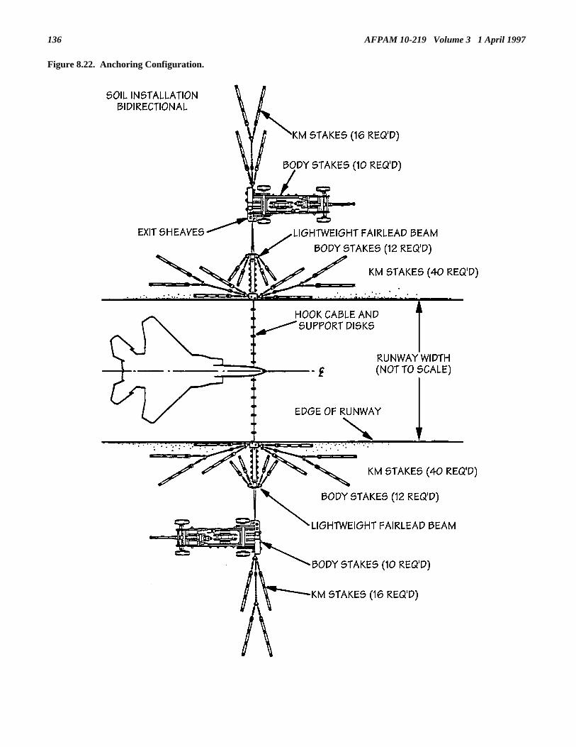
AFPAM 10-219 Volume 3 1 April 1997136
Figure 8.22. Anchoring Configuration.

AFPAM 10-219 Volume 3 1 April 1997 137
8.4. Expeditionary Systems. As implied by the name, expeditionary arresting systems are those which can be relocated to apoint of operation and quickly set up to engage landing aircraft. Depending upon the amount of time available for installation,the configuration of these systems in their expeditionary location can range from expedient to a permanent installation. For thecontingencies anticipated in this publication, an expedient installation will be required. A few of the BAK-12 systemsdiscussed here are included as components of WRM and should be available during wartime contingencies.8.4.1. BAK-12 Aircraft Arresting System. The operation of the BAK-12 system (figure 8.23) is similar to the MAAS and, infact, they share some of the same major components. The BAK-12 system is a rotary friction type emergency absorberconsisting of two identical units installed on each side of the runway. The two energy absorbers are joined across the runwayby a hook cable or by a nylon barricade net.
Figure 8.23. BAK-12 Aircraft Arresting System.
8.4.1.1. The aircraft arresting cable can be set up in two distinct configurations. To facilitate engagement by arresting hookequipped aircraft, the hook cable can be suspended several inches above the MOS by rubber discs. The other option is a systemwhich is elevated on demand by a remotely controlled system activated from the air base control tower. For aircraft notequipped with a arresting hook, the nylon barrier net is used for arrestment. When not in use, the net is stretched taut over thesurface of the overrun to allow for aircraft roll over. Like the cable system, erection of the nylon net is remotely controlledfrom the airfield control tower. When the base expects to recover both types of aircraft, the BAK-12 can be equipped with anet/cable interconnect device to ensure that either type can be safely arrested.8.4.1.2. The following paragraphs offer additional information regarding expeditionary employment of the BAK-12 arrestingsystem.8.4.1.2.1. Installation Flexibility. The BAK-12 is air transportable and can be readily installed anywhere in the world. Formore established installations, the common procedure is to bolt each absorber to a concrete pad for surface installation or in aconcrete pit for below grade installation. However, the system can also be installed in an expeditionary configuration usingearth anchors. This installation requires approximately 100 manhours of effort within an elapsed time of 10 clock hours.8.4.1.2.2. Bi-directional. The BAK-12 is capable of arresting in either direction.8.4.1.2.3. Self-Contained. The fact that the BAK-12 is a completely self contained system makes it an ideal candidate forexpeditionary employment during a contingency situation. It operates from a gasoline engine which is an integral component ofthe system and does not require a source of external power, water, or compressed air.8.4.1.2.4. Topography. Proper BAK-12 operation requires installation on a reasonably flat surface. Therefore, thetopography of the proposed installation area must be carefully examined to determine installation requirements and alterations.Shoulder elevations should be taken at 5 feet intervals out to 25 feet from the edge of the runway or overrun and grading shouldbe accomplished during construction to meet leveling requirements. The area should be well drained and free of obstructionswhich could interfere with the normal operation of the arresting system.8.4.1.2.5. Expeditionary Installation. Expeditionary installations of the BAK-12 should be used only for support of tactical

AFPAM 10-219 Volume 3 1 April 1997138
operations at airfields where quick, economical installations are needed. As with any barrier installation, careful site planningand scheduling of the installation effort are essential. Currently, Civil Engineer RED HORSE Squadrons and two speciallytrained overseas units are the only personnel capable of installing the BAK-12 system in the expeditionary mode. The barrier isto be positioned to allow for a minimum aircraft run-out of at least 950 feet after engagement and 1,000-1,500 feet of crater freepavement ahead of the barrier cable (figure 8.24). The 1000-1500 feet are necessary to avoid catching the arresting hook on arepair cover or bouncing the aircraft arresting hook over the barrier cable.
Figure 8.24. Expeditionary Barrier Positioning.
8.4.1.2.6. Expeditionary Operation. When used as an emergency system, the BAK-12 is normally unattended and operatesautomatically when an aircraft engages the pendant. A minimum three- to four-member barrier crew will be required to retractand reset the system. Two of the crew members operate the retract engines and the remaining one or two personnel act assignalmen. The crew size used is normally dependent on the width of the runway or MOS that the barrier is serving.Installation and operation instructions beyond the detail of this publication are contained in Air Force T.O. 35E8-2-5-1.
8.5. Summary. Aircraft arresting systems are important for any air base that supports the operation of high performance fighteraircraft. The systems are especially important during contingency situations because damaged or degraded pavement surfacesmay require a greater frequency of aircraft arrestments. There are two primary types of arresting systems that may be used tomeet these requirements--expeditionary and mobile systems. The BAK-12 arresting system in the expeditionary configurationhas historically been used and a few are still in the Air Force inventory. More than likely, however, the newer mobile aircraftarresting or MAAS will be the equipment mainstay for current and future Air Force needs. The MAAS can be installed on soil,asphalt over soil, asphalt over concrete, and concrete surfaces. While installation techniques for each type of surface differ, awell-trained barrier installation team can put this type of arresting barrier into service in less than 1 hour.

AFPAM 10-219 Volume 3 1 April 1997 139
Chapter 9
MOBILE AIRFIELD LIGHTING SYSTEMS
9.1. Introduction. For an air base to be considered fully operational following an attack or contingency, it must be capableof supporting both daytime and nighttime aircraft operations. To ensure that nighttime operations can be conducted, therunway must have an effective lighting system. If the existing lighting system is damaged, you must either make repairsquickly and effectively using all available means, or install and operate a mobile airfield lighting system until such time thatpart or all of the existing lighting system can be brought back into service.
9.2. Overview. This chapter describes the characteristics of standard airfield lighting systems and their various components.It also discusses the various types of conditions under which airfield lighting systems could experience damage and mobileairfield lighting systems might have to be installed (expedient repairs to existing airfield lighting systems are covered inchapter 7). Three primary types of mobile airfield lighting systems are addressed--the Harvest Eagle set, the rapid runwayrepair (RRR) lighting set, and the emergency airfield lighting system (EALS). Lastly, airfield lighting crew sizes andresponsibilities are addressed.
9.3. Characteristics of Airfield Lighting Systems.9.3.1. Runway Lighting Systems. A runway lighting system consists of a power source, lighting aids, and systemcomponents. A high intensity runway lighting system is the basic type of installation used by the Air Force. However, amedium intensity runway lighting system may be installed on runways which are not used under instrument flight rules (IFR)conditions due to impaired clearances, short lengths, or other contingency factors. The designations high intensity andmedium intensity are derived from the candlepower output performance of the lights with the high intensity lights using 200-to 500-watt lamps and the medium intensity lights using 40- to 45-watt lamps.9.3.2. Lighting Aids. Lighting aids are designed and provided to improve the operational safety for aircraft and pilots duringtakeoff and landing operations. Lighting aids consist of runway edge lights, taxiway lights, threshold lights (in-board, wingedout, and prethreshold), termination bar lights, approach lights, strobe lights, runway and identifier lights, visual glide slopeindicator lights, aircraft arresting barrier lights, distance-to-go marker lights, airport beacons, and obstruction lights.9.3.3. Major System Components.9.3.3.1. Airfield lighting systems are generally high voltage series lighting circuits employing heavily insulated conductors,isolating transformers, and constant current regulators. In a series circuit there is only one path for current flow. If that pathis broken, current will not flow. In an airfield lighting circuit, isolating transformers are installed at every point a lighting aid(edge light, taxiway light, approach light, etc.) is required. The primary side of each isolating transformer is connected inseries with the high voltage cables from the power source. The secondary side of the isolating transformer connects to alighting fixture. If the bulb in that light fixture burns out, it will not impact the series circuit since it is isolated from thatcircuit. If isolating transformers were not used, the total circuit would become inoperative when one lamp burned out.9.3.3.2. The primary conductors used in airfield lighting are heavily insulated high voltage, single conductor cables that canbe placed underground as direct burial or inside a conduit or network of ducts. The duct system is considerably more costlyto install but the cables inside are more easily repaired than when they are buried directly in the ground. If the ducts are notdamaged, defective conductors can be readily replaced.9.3.3.3. Current regulators provide power to the circuit at a constant rate and will adjust current output to the changing loadas lamps become inoperative. Current regulators can also be used to change the current for adjusting the brightness of thelights to suit weather conditions. The current regulators are located in the airfield lighting vault. The airfield lighting vaulthouses the power distribution and control equipment for all runway and taxiway lighting circuits and for other airfield lightingthat can feasibly use this source. The airfield system is generally controlled from two points: the control tower and theairfield lighting vault.
9.4. Potential Conditions Necessitating Mobile Airfield Lighting Use.9.4.1. Natural Disaster. The effects of natural disasters can cause serious disruption and damage to airfield lightingsystems. Earthquakes, for example, can sever and stretch underground cables and destroy lighting vaults and control towers.The high winds and flying debris associated with tornadoes and hurricanes can shatter fixtures, tear down distance-to-gomarkers, and destroy airfield lighting support structures. Another potential threat is that of flooding during hurricanes ortorrential rainstorms wherein lighting equipment and power supplies are inundated with water, silt and floating debris.Natural disasters of this magnitude will, in all likelihood, cause damages requiring lengthy repair times. The use of a mobileairfield lighting system becomes a highly attractive, and perhaps the only, option for restoring round-the-clock flyingoperations.9.4.2. Deployment to Austere Locations. The employment of a mobile airfield lighting system is a necessity at many

AFPAM 10-219 Volume 3 1 April 1997140
locations. Show-of-force, humanitarian relief, civic action, and other similar operations could require the use of airfields inremote, undeveloped regions. Potentially there could be airfields with no lighting installed or systems that are inoperative. Insome cases the airfield could be little more than an assault strip.9.4.3. Base Recovery After Attack (BRAAT).9.4.3.1. Perhaps the most demanding need for mobile airfield lighting systems stems from the requirements generated bywartime conditions. With airfield pavements being one of the major targets during wartime, the likelihood of extensiveairfield lighting damage is high. The subsequent choice of minimum operating strip (MOS) is normally performed with only aperipheral consideration of airfield lighting capabilities--airfield lighting is not a key factor in MOS selection. This situationleads to at least three potential options with respect to MOS selection and the associated airfield lighting support:• A selected MOS on the runway that cannot possibly be supported by the existing in-place airfield lighting system.• A selected MOS on the runway that can be supported by a segment of the existing lighting system.• A selected MOS off of the runway surface.9.4.3.2. Any of the above three conditions require the use of all or at least a part of a mobile airfield lighting system forsupport of round-the-clock flying operations.
9.5. Mobile Airfield Lighting Systems. Currently three mobile airfield lighting systems exist in the Air Force inventory.The systems are the rapid runway repair, Harvest Eagle and Harvest Falcon sets. All of these systems can be used in barebase beddown situations even though the RRR set is intended to support rapid runway repair situations. The Harvest Eagleset, while meant to support bare base beddown situations, has a further use in supporting rapid runway repair and BRAAToperations. The components in the Harvest Eagle set and the RRR set are essentially the same. The major difference is howthe two sets are deployed. The Harvest Eagle set is deployed as part of a larger Harvest Eagle beddown package, while theRRR set is prepositioned primarily at theater bases with a high threat. The Harvest Falcon airfield lighting set, called theemergency airfield lighting set (EALS), also has a dual role of supporting both beddown and base recovery requirements.Once the EALS is procured in sufficient quantities, it will replace the Harvest Eagle lighting set. Details concerning thelayout of the various components of these sets is provided in volume 9 of this series.9.5.1. Harvest Eagle Airfield Lighting Set.9.5.1.1. The Harvest Eagle airfield lighting set is a 6.6 ampere, high intensity lighting system that can provide threshold andrunway edge lighting for up to 10,000 feet of bare base runway. The set does not include approach lights, strobe lights,barrier marker lights, distance marker lights, or any sort of lighted visual glide path indicators. The components of the set arehighly reliable and are identical to items currently used in permanent installation of airfield lighting systems at military andcivilian airfields around the world. In the event of a deployment to a bare base where the airfield lighting is inoperative, theHarvest Eagle set can be used to repair the existing systems or, if damaged beyond repair, to set up a completely independentsystem. Major components of this set include:9.5.1.1.1. Light Mounts (132 each). Metal stakes are used to support the lights. The metal stake is driven into the groundand supports a type C-1 runway light fixture.9.5.1.1.2. Cable Assembly (39,000 feet). Most of the assembly consists of number 8 conductor (36,000 feet). In some casesthis cable could be made up of a number of 205-foot sections with precast rubber male and female connections at either end.If the cable is on reels, it will have to be cut to length and fitted with appropriate connectors. Also included is 3,000 feet of 7conductor cable used to interconnect control panels and regulators.9.5.1.1.3. Colored Lenses (64 each). Thirty-two green and 32 red lens filters are included for use in setting up the thresholdlights.9.5.1.1.4. Lamps (240 each). Clear lens lamp assemblies use 200-watt, 6.6 amp bulbs.9.5.1.1.5. Light Fixtures (132 each). The C-1 runway light fixture is used for edge and threshold lighting by changing bulbsand lens filters (figure 9.1).

AFPAM 10-219 Volume 1 1 April 1997 141
Figure 9.1. C-1 Airfield Lighting Fixture Wiring Diagram.
9.5.1.1.6. Transformers (160 each). Transformers are required for each lamp assembly to isolate the lamp circuit from theseries feeder circuit (figure 9.1).9.5.1.1.7. Regulators (3 each). The 15 kW regulators provided consist of static-type, constant-current regulator assembliesdesigned to deliver a constant current to the series lighting circuit. Normally, two regulators are used during systeminstallation with the third acting as a backup spare.9.5.1.1.8. Emergency Bean Bag Lights (200 each). These are small, portable lights, powered by 6-volt lantern batteries.Used when runway edge lights are inoperative, these units are set up along the operating strip at 200-foot intervals and turnedon and off manually.9.5.1.1.9. Power Source (2 each). Two 60 kW, 60 cycle generators are provided for the set. These generators provide thecapability to install airfield lighting within hours of employment at a bare base or shortly after an attack has occurred. If thebare base is to eventually have a power grid installed, the generators carry the airfield lighting system until such time that thelighting can be connected to the power grid. Once the lighting is connected to the grid, the generators then provide essential200 percent backup capability should the bare base power grid fail.9.5.1.1.10. Accessories. Accessory components include batteries for portable bean bag lights, tape for making splices, and acontrol panel to allow remote control of the lighting circuits.9.5.2. Rapid Runway Repair Lighting Set. The RRR airfield lighting set contains essentially the same items as the HarvestEagle lighting set but in somewhat lesser quantities. The RRR airfield lighting set can support a MOS up to approximately9000 feet long. Figure 9.2 depicts the use of the RRR lighting set on a nominal 50’ by 5,000’ MOS.

AFPAM 10-219 Volume 3 1 April 1997142
Figure 9.2. RRR Airfield Lighting Layout.
9.5.2.1. Set up of Harvest Eagle lighting components is not technically complex but several "tricks of the trade" andinstallation considerations should be mentioned. The following data is provided for installation of RRR Harvest Eaglecomponents under base recovery conditions but much of it would also apply when operating in a beddown mode.9.5.2.1.1. Determine Layout of Components. Layout of components is greatly facilitated by the efforts of the MOS layoutcrew when it places the traffic cones at the ends and down the centerline of the MOS. The cones basically show the spacingof required airfield lights (see volume 4 for details). If installation of airfield lighting occurs toward the end of or after RRRcrater repair operations, the orange "A" frame edge markers placed by the MOS marking team provide even more definitivereference points.9.5.2.1.2. Spacing. Runway edge lights should be installed along both sides of the MOS at intervals no greater than 200 feet.Each pair of lights, one on each side of the landing strip, should be placed as nearly as possible opposite each other. The tworows of lights should be located 4 to 10 feet off the edge of the MOS. The threshold lights should be spaced 5 feet apart andno further than 10 feet from the end of the MOS.9.5.2.1.3. Regulator and Power Source Positioning. The regulators and supporting generators should be installed in anadvantageous location, but sufficient distance (about 750’) from the MOS so as not to constitute an obstruction for aircraft. Inaddition, they should also be situated on a level and well drained surface. Keep in mind that a control panel for the systemwill, in all likelihood, eventually have to be located in the control tower. The amount of seven conductor cables available willdictate, to a great extent, where the regulators and generators will be positioned with respect to the control tower. During theinitial phases of base recovery, however, airfield lighting will be controlled in the field.9.5.2.1.4. Wiring Connections. When the location of the lights has been determined, cable assemblies should be laid outalong the MOS. At each location where a lamp assembly is to be installed or other connection made, plugs or receptacles willbe required. Appropriate connections are provided when preassembled 205’ cable assemblies are used. When they are notavailable and the airfield lighting circuits are made up in the field from bulk cable on a reel, the cable is cut in 205’ lengths,and male and female plugs are installed at each light fixture. The ends of each series airfield lighting circuit should bebrought out to the location where the regulators are. One rubber covered isolating transformer is installed at every lightlocation.9.5.2.1.5. Light Installation. The metal stakes provided in the lighting set are designed for use in soil or compacted fillwhich applies well to installation just off the runway edge during a beddown situation. They, however, will not work inconcrete, AM-2 matting or other equally hard surface. In a base recovery mode chances are you will be facing a conditionwhere lights will have to be placed on existing pavement surfaces at least on one side of the MOS, if not both. Imaginationand innovation will be the key to solving the problems created by surface variations. Here are three suggestions for securinglight fixtures to hard surfaces.9.5.2.1.5.1. Traffic Cones. Traffic cones are very adaptable to a variety of situations. Most cones must be altered by cuttingdown the tip just enough to squeeze in the C-1 frangible coupler. If the larger cones are used they are normally big enough toalso house the isolation transformer. In this fashion, the isolating transformer is provided some measure of protection from

AFPAM 10-219 Volume 1 1 April 1997 143
the elements and the transformer itself provides a ballast effect against wind and jet blast to hold the light in place. The conescan then be secured to earth or asphalt by using large spikes driven through the lip of the cone. A piece of 1/2-inch plywoodand two pieces of 2" by 4" can be added to allow "ram setting" to harder surfaces. The plywood base must be drilled to allowcables to pass. The 2" x 4"s are used to raise the assembly high enough to allow cable to pass under the base (figure 9.3).This configuration can also be secured with the help of two sandbags. Traffic cones also aid in identifying the MOS in thedaylight when the lights are off.
Figure 9.3. Traffic Cone Mount with Plywood Base.
9.5.2.1.5.2. Plywood or Steel Platform. The plywood platform is an adaptation of the traffic cones (figure 9.4). Theplywood should be 3/8-inch or greater. A hole cut in the plywood base permits a tight fit of the frangible coupler. It issecured in the same manner described for the traffic cone. Again, 2" x 4"s are used to provide enough elevation to allowcables to pass under the platform. The transformer can be placed on the plywood base to help hold it in place. Steel can alsobe used (figure 9.5).
Figure 9.4. Plywood Platform Mount.

AFPAM 10-219 Volume 3 1 April 1997144
Figure 9.5. Steel Base Mount.
9.5.2.1.5.3. H-Frame. The H-frame is a variation of the plywood platform method. With this variation the plywood isreplaced with a single 12-inch 2" by 4" (figure 9.6). The 2" x 4" is cut or drilled in the center to allow a tight fit of the C-1frangible coupler. It is secured in the same manner as the methods previously described.
Figure 9.6. H-Frame Mount.

AFPAM 10-219 Volume 1 1 April 1997 145
9.5.2.1.5.4. Edge Light Orientation. It is necessary to orient or adjust the edge light assembly equipped with asymmetric(clear) lenses so that the two main beams of each light are aligned with the edge of the MOS.9.5.3. Emergency Airfield Lighting System (EALS). The emergency airfield lighting system represents a markedimprovement over the existing Harvest Eagle airfield lighting set. It can be configured for both a beddown operation and aRRR operation.9.5.3.1. Beddown Mode. For a bare base situation, the EALS can support a runway up to 150 feet wide and 10,000 feetlong. It can be installed and secured on all types of surfaces (e.g., sand, frozen earth, mud, ice, asphalt, and concrete) andincludes edge lighting, approach lighting, threshold/end lighting, taxiway lighting, visual glide slope indication, distance-to-gomarker lighting, and obstruction lighting. Also included are two generators, two regulators, two control panels, and numeroustransformers and lengths of cable. The set is packaged in six trailers (figure 9.7) and can be airlifted by C-130 aircraft(requires three pallet positions). Typical layouts of various components of the set are shown in figures 9.8 through 9.11.Details relative to the set up and operation of the EALS can be found in TO 35F5-3-17-1.
Figure 9.7. EALS Trailers.

AFPAM 10-219 Volume 3 1 April 1997146
Figure 9.8. EALS General Layout.

AFPAM 10-219 Volume 1 1 April 1997 147
Figure 9.9. EALS Distance-To-Go Marker Light, Edge Light and PAPI Layout.
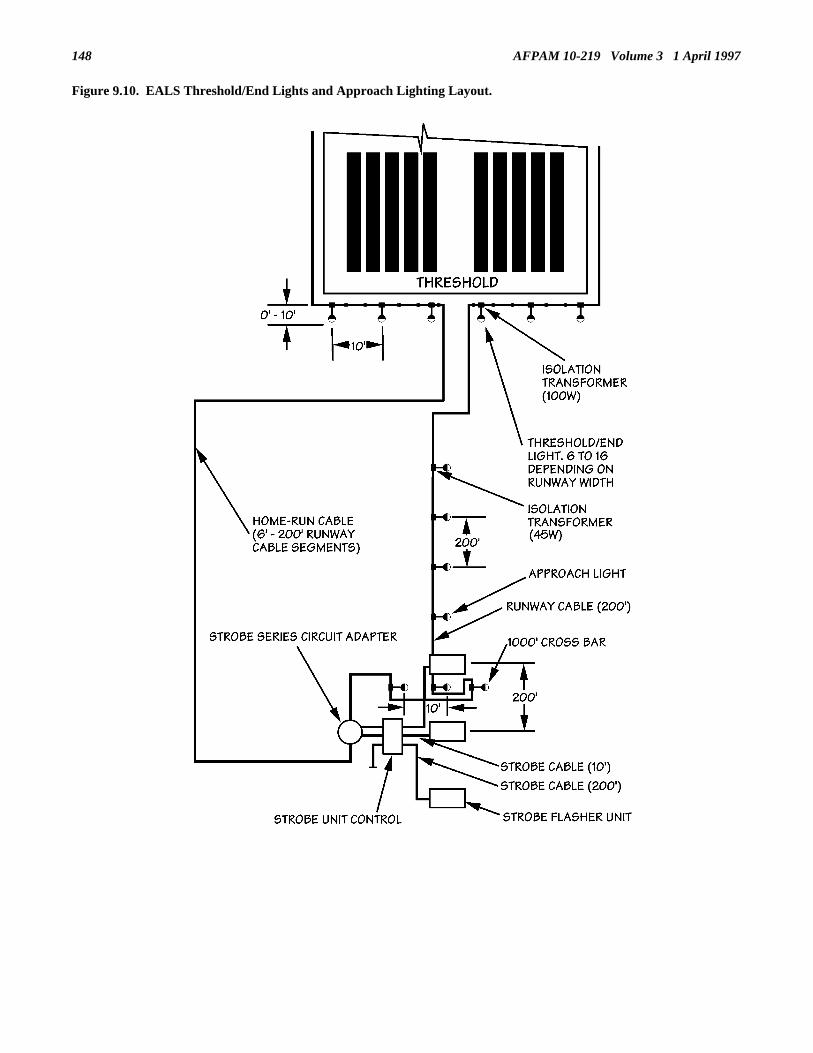
AFPAM 10-219 Volume 3 1 April 1997148
Figure 9.10. EALS Threshold/End Lights and Approach Lighting Layout.

AFPAM 10-219 Volume 1 1 April 1997 149
Figure 9.11. EALS Taxiway Lighting Layout.
9.5.3.2. RRR Mode. The EALS used for RRR operations is basically a subset of the full system that is geared towardsupporting the nominal MOS size of 50’ by 5,000’. It utilizes four of the six trailers included in the complete system. TheMOS configuration is also C-130 transportable, requiring two pallet positions. When installed as part of the BRAATresponse operation, the system provides the same airfield lighting support capabilities as those provided by the full system ina beddown mode. Fewer components are used, however, due to the smaller size of the takeoff and landing surface. Underideal conditions a six-person crew using two general purpose vehicles can install the EALS for a 5,000’ MOS in 2-1/2 hours.9.5.3.3. Set Components. The major components on the EALS are described in the following paragraphs. The quantities ofcomponents listed correspond to the full EALS system.

AFPAM 10-219 Volume 3 1 April 1997150
9.5.3.3.1. Edge/Approach Lights (106 each). These are 45-watt lights with a clear lens (figure 9.12).
Figure 9.12. EALS Edge and Approach Lights.
9.5.3.3.2. Threshold/End Lights (33 each). These are 120-watt lights with a split red/green lens (figure 9.13).
Figure 9.13. EALS Threshold and End Lights.
9.5.3.3.3. Taxiway Lights (40 each). These are 30-watt lights with a blue lens (figure 9.14).

AFPAM 10-219 Volume 1 1 April 1997 151
Figure 9.14. EALS Taxiway Lights.
9.5.3.3.4. Distance-to-go Marker Lights (10 each). These are 45-watt PAR 38 lamps.9.5.3.3.5. Isolation Transformers. These items come in two sizes--45-watt and 100-watt. There are 163 of the lowerwattage and 33 of the higher (figure 9.15).
Figure 9.15. EALS Isolation Transformers.
9.5.3.3.6. Strobe Flasher Units (7 each). Three of these strobe lights are placed in the approach zone on both ends of therunway or MOS (figure 9.16). These strobe lights can be operated from the control panel independently from the remainderof the airfield lighting system.

AFPAM 10-219 Volume 3 1 April 1997152
Figure 9.16. EALS Strobe Flasher and Circuit Adapter Units.
9.5.3.3.7. Strobe Control Units (3 each). One of these units is placed in the approach zone on both ends of the MOS tocontrol the strobe lights (figure 9.16).9.5.3.3.8. Precision Approach Path Indicator (PAPI) (3 each). One of these units is placed on the left side of both ends ofthe runway or MOS in the vicinity of the touchdown points (at approximately the 950-foot points). They give a pilot a visualindication of his or her position on the glide slope leading to the runway or MOS (figure 9.17).
Figure 9.17. EALS PAPI Unit.
9.5.3.3.9. Obstruction Lights (10 each). These are small battery operated red lights. They are manually controlled.9.5.3.3.10. Taxiway Reflectors (252 each). These items are 2-inch diameter, 8-inch high reflecting rods which are placedalong unlighted portions of access taxiways.

AFPAM 10-219 Volume 1 1 April 1997 153
9.5.3.3.11. Cable. Over 35,000 feet of cable in varying lengths and gauges are included for connecting lights, regulators,generators, etc. (figure 9.18). Also included are cable protectors (figure 9.19) for taxiway crossing locations.
Figure 9.18. EALS Cable.
Figure 9.19. EALS Cable Protectors.
9.5.3.3.12. Regulators (2 each). One of these 20 kW constant current regulators (figure 9.20) is used to power in series allthe lighting equipment except the obstruction lights. Each regulator has three intensity levels (4.8 amps, 5.5 amps, and 6.6amps) that can be selected at the control panel. Changing the intensity setting of the regulator changes the intensity of theedge lights, approach lights, threshold/end lights, taxiway lights, and distance-to-go marker lights.
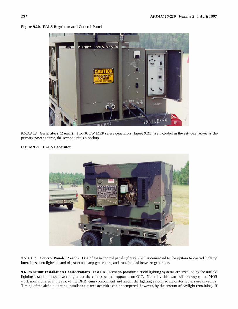
AFPAM 10-219 Volume 3 1 April 1997154
Figure 9.20. EALS Regulator and Control Panel.
9.5.3.3.13. Generators (2 each). Two 30 kW MEP series generators (figure 9.21) are included in the set--one serves as theprimary power source, the second unit is a backup.
Figure 9.21. EALS Generator.
9.5.3.3.14. Control Panels (2 each). One of these control panels (figure 9.20) is connected to the system to control lightingintensities, turn lights on and off, start and stop generators, and transfer load between generators.
9.6. Wartime Installation Considerations. In a RRR scenario portable airfield lighting systems are installed by the airfieldlighting installation team working under the control of the support team OIC. Normally this team will convoy to the MOSwork area along with the rest of the RRR team complement and install the lighting system while crater repairs are on-going.Timing of the airfield lighting installation team’s activities can be tempered, however, by the amount of daylight remaining. If

AFPAM 10-219 Volume 1 1 April 1997 155
considerable daylight will remain after MOS pavement repairs are complete, the installation team can be tasked with otherequally critical repair requirements elsewhere and return to the MOS at a later time to set up the lighting system.9.6.1. Manning and Equipage. A minimum of four personnel are required for installation of the existing RRR airfieldlighting set composed of Harvest Eagle type components. The EALS requires six personnel due to the increased number ofcomponents and fixtures. At least two of the team members must have an electrical system (AFSC 3E0X1) background. Theremainder can be from the electric power production (AFSC 3E0X2) field. Two general purpose vehicles are necessary forcrew movement and delivery of components around the MOS. Fork lift support is necessary for placement of the generatorsand regulators. Required tools are either in the standard mobility tool kits or included as part of the lighting sets themselves.Under ideal conditions either type of lighting set can be installed in 2-1/2 hours.9.6.2. Other Support Considerations. The performance of the airfield lighting installation team is influenced by theactivities of other RRR team and base recovery crews. The RRR support team OIC must coordinate these efforts to ensurelighting system set up progresses satisfactorily.9.6.2.1. Explosive Ordnance Disposal (EOD) Support. Since the airfield lighting installation team will be working in areassomewhat distant from the MOS perimeter, EOD personnel must search these areas for unexploded ordnance and remove orsafe any such items found. Of particular importance are the MOS overruns where approach and strobe lighting will beinstalled and the infield areas where the regulators, generators, and PAPI units will be placed.9.6.2.2. Foreign Object Damage (FOD) Removal Team Support. In those areas where debris blocks set up of fixtures orcomponents or hinders cable placement, the FOD removal team must perform clearance actions.9.6.2.3 MOS Marking Team. Early and proper placement of MOS end, centerline, arresting barrier and PAPI locationcones by the MOS marking team can greatly simplify the airfield lighting installation process since locations and spacings forfixtures will be identified. If the MOS marking team has been able to place all of the edge and distance-to-go markers by thetime the lighting team arrives on-scene, the airfield lighting installation process is even more simplified since precise locationsfor fixtures will then be known. The airfield lighting team, however, retains responsibility for picking up the PAPI andapproach lighting marking cones once the systems are installed and ensuring that all edge lighting fixtures are 1-foot inside ofthe edge markers.
9.7. Summary. A runway or MOS is not considered fully operational without an airfield lighting system. As a minimum anairfield requires sufficient lighting to mark the edges and ends of the takeoff and landing strip. Ideally, an airfield should alsohave approach lighting, strobe lighting, distance-to-go marker lighting, and a visual glide path indicator lighting system. If anairfield does not have the basic lighting needs installed or existing lighting systems are inoperative or damaged beyondimmediate repair by enemy attack, a portable lighting system will have to be installed. Three portable airfield lightingsystems exist today that can be used to meet the airfield lighting requirements--the RRR lighting system, the Harvest Eaglelighting system, and EALS. The RRR lighting set is the least capable of the three systems, generally limited to lighting theMOS after base recovery has occurred. The Harvest Eagle system is somewhat larger than the RRR set and can serve a largerairfield surface. The components of these two sets are essentially identical except for quantities. The EALS is the mostcapable of the three systems having strobe lighting, approach lighting, PAPI lighting, and distance marker lighting inadditional to edge and end lights. Currently part of the Harvest Falcon mobility package, the EALS will also eventuallyreplace the Harvest Eagle lighting system.
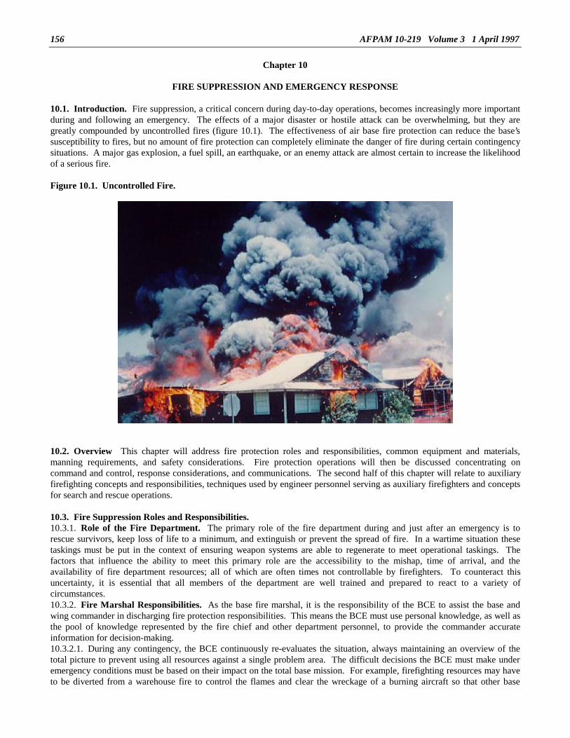
156 AFPAM 10-219 Volume 3 1 April 1997
Chapter 10
FIRE SUPPRESSION AND EMERGENCY RESPONSE
10.1. Introduction. Fire suppression, a critical concern during day-to-day operations, becomes increasingly more importantduring and following an emergency. The effects of a major disaster or hostile attack can be overwhelming, but they aregreatly compounded by uncontrolled fires (figure 10.1). The effectiveness of air base fire protection can reduce the base’ssusceptibility to fires, but no amount of fire protection can completely eliminate the danger of fire during certain contingencysituations. A major gas explosion, a fuel spill, an earthquake, or an enemy attack are almost certain to increase the likelihoodof a serious fire.
Figure 10.1. Uncontrolled Fire.
10.2. Overview This chapter will address fire protection roles and responsibilities, common equipment and materials,manning requirements, and safety considerations. Fire protection operations will then be discussed concentrating oncommand and control, response considerations, and communications. The second half of this chapter will relate to auxiliaryfirefighting concepts and responsibilities, techniques used by engineer personnel serving as auxiliary firefighters and conceptsfor search and rescue operations.
10.3. Fire Suppression Roles and Responsibilities.10.3.1. Role of the Fire Department. The primary role of the fire department during and just after an emergency is torescue survivors, keep loss of life to a minimum, and extinguish or prevent the spread of fire. In a wartime situation thesetaskings must be put in the context of ensuring weapon systems are able to regenerate to meet operational taskings. Thefactors that influence the ability to meet this primary role are the accessibility to the mishap, time of arrival, and theavailability of fire department resources; all of which are often times not controllable by firefighters. To counteract thisuncertainty, it is essential that all members of the department are well trained and prepared to react to a variety ofcircumstances.10.3.2. Fire Marshal Responsibilities. As the base fire marshal, it is the responsibility of the BCE to assist the base andwing commander in discharging fire protection responsibilities. This means the BCE must use personal knowledge, as well asthe pool of knowledge represented by the fire chief and other department personnel, to provide the commander accurateinformation for decision-making.10.3.2.1. During any contingency, the BCE continuously re-evaluates the situation, always maintaining an overview of thetotal picture to prevent using all resources against a single problem area. The difficult decisions the BCE must make underemergency conditions must be based on their impact on the total base mission. For example, firefighting resources may haveto be diverted from a warehouse fire to control the flames and clear the wreckage of a burning aircraft so that other base

AFPAM 10-219 Volume 3 1 April 1997 157
aircraft can take-off and land. Each situation will require two important considerations--how to respond to the hazard, andhow the decision impacts on the overall mission capability. In the above example, saving the warehouse at the expense offlying operations might have jeopardized the entire base mission.10.3.2.2. Fire response to contingencies places the BCE in a position of awesome responsibility, but there is virtually nosituation that cannot be overcome by the application of the collective experience of the civil engineer force and theimplementation of well rehearsed contingency response procedures. An understanding of the decision-making process forcontrolling hazards will greatly enhance the BCE’s effectiveness as base fire marshal. First, when a hazard is discovered,immediate action is taken to contain the situation. This may require evacuation of a building, interruption of utilities serviceto the affected site, and discontinuation of an on-going activity, e.g., aircraft refueling, or welding in a dangerous area. TheBCE joins the fire chief in a joint inspection of the hazard situation. The responsible organizational commander is alsoalerted of the problem and advised of necessary corrective action. If these steps do not resolve the problem, the BCE advisesthe base commander who makes a decision to continue or cease the hazardous operation. The base safety officer must also beinformed promptly. The point is: do not make decisions for higher authority unless time and imminent hazard require you todo so; then advise the commander of your decision immediately.10.3.2.3. The discussion in the previous paragraph outlines a process found to be effective in preattack situations and thoseinstances where time is available for a more methodical approach. In a postattack environment, however, time will not beavailable for a predetermined step-by-step approach and hazardous and emergency conditions will be much more numerous.Because of the emergency and expedient nature of the postattack environment, some situations which would be consideredhazardous in peacetime or under preattack conditions will have to be tolerated. Additionally, joint on-scene meetings of keypersonnel and notification of several different base agencies will not be feasible for every emergency occurrence. Delegationof authority to fire department personnel, e.g., the fire chief or other on-scene command and control fire personnel, will benecessary. They will have to know the responsibilities of the base fire marshal and often times make the decisions appropriateto this position since the base fire marshal will be serving in the much broader role of base civil engineer on the survivalrecovery center staff. Inherent in this tasking is the need for these individuals to understand how their response to a specificemergency impacts the base mission as a whole. For example, evacuating a sizable area which might be done in peacetimefor safety purposes, may be a severe mission hindrance in wartime in that it could interfere with aircraft turn-around oractivities of other emergency base recovery crews. The ability to be flexible, realistically assess risk, and maintain an overallbase mission perspective is needed on the part of fire command and control personnel. It is the base fire marshal’s job toensure fire fighting personnel gain this experience, knowledge, and expertise prior to a wartime or contingency situation.10.3.3. CONUS Versus Theater Fire Suppression. The procedures for fire suppression are similar for the CONUS andtheater locations. Minor differences involve available manpower and types of emergencies.10.3.3.1. CONUS locations are not subject to rapid conventional attacks which could quickly engulf a theater air base inflames. However, broken gas mains and ruptured POL storage tanks during an earthquake at a CONUS airfield couldproduce similar results. The CONUS fire department must be capable of responding to fires under two conditions--with a fullcomplement of military and civilian personnel available and with civilians only, when military Prime BEEF members aredeployed. The limitations imposed by deployments make it essential that high priority facilities receive first response fromthe reduced firefighting force during large scale fires. Reciprocal agreements with off-base fire departments will paydividends during emergencies when the residual firefighting force is at diminished strength. Civilian firefighters must beaware that their services will be more demanding when military firefighters are deployed. They should expect to be placed onextended or altered shifts and take a fully active role in all leadership positions. If conditions permit eventual backfills withmilitary firefighting personnel from other units, these individuals must be integrated into the CONUS base firefighting forcerapidly and effectively. Programs for thorough base familiarization and specialized training, e.g., wide-frame aircraftfirefighting at an aerial port, must be immediately available for these augmenting personnel.10.3.3.2. The theater BCE must execute fire suppression plans under the prevailing threat of both rapid conventional attackand natural disasters (see attachment 2 for details pertaining to the fire protection wartime concept of operations). Since thetheater BCE’s military forces are normally in-place, major loss of forces due to deployments should not be a limiting factor.The BCE’s civilian firefighters should be available for natural disaster response, but in some locations their wartimeavailability could be suspect. At most locations Prime BEEF firefighting teams from the CONUS should be augmentingtheater forces and in-place prior to hostilities as part of the USAF deterrent force posture. The USAF fire chief at eachaugmented theater base must ensure that these augmenting forces are quickly integrated into the base’s fire protectioncapability and trained on support of the weapon systems assigned to that base. In the event, however, that augmenting forceshave not arrived, each theater installation should be prepared to operate, at least initially, with in-place military forces only.Even if the BCE has a full complement of firefighters available, the fires resulting from a massive enemy attack can quicklyoverwhelm a fully staffed fire department. For this reason, theater forces, like their CONUS counterparts, must also beprepared to react to fires on a priority basis.10.3.3.3. At some theater locations there may be no USAF firefighters in-place. Typical of such situations could be a barebase operation where only a token host nation firefighting presence exists. A bare base operation of this type places uniqueand difficult demands on deployed Prime BEEF firefighter personnel. The USAF fire chief and supporting fire department

AFPAM 10-219 Volume 3 1 April 1997158
personnel must take several actions quickly upon arrival to establish a fire protection and crash rescue response posture. Themore important tasks that must be accomplished include the following:10.3.3.3.1. Determine in concert with host nation firefighting personnel who is responsible for what in terms of areas,facilities, weapon systems, etc.10.3.3.3.2. Determine similar responsibilities as above with firefighting personnel of other U.S. military services if they arealso present at the bare base location.10.3.3.3.3. Ascertain the status and availability of firefighting assets that will be used by USAF forces.10.3.3.3.4. Train firefighting personnel on assets that are unique or differ significantly from those in the USAF inventory.10.3.3.3.5. Familiarize firefighting personnel with the base layout and critical facilities and systems.10.3.3.3.6. Ensure fire protection features are incorporated into the layout, erection, and construction of tent cities and othermobile facility assets.10.3.3.3.7. Determine shortfalls and supply and equipment requisition needs.10.3.3.3.8. Develop operating procedures for use during trans and postattack timeframes.10.3.4. Safety Responsibilities. Firefighting personnel have a responsibility both to themselves and to the base populacewith respect to safety. Any major firefighting operation is inherently dangerous and must be undertaken only by skilledpersonnel familiar with the hazards involved.10.3.4.1. The maintenance of fire safety is a greater problem in contingency situations than during normal, day-to-dayoperations. Conditions which are likely to prevail during an emergency require a greater awareness and adherence to firesafety practices. Temporary shelters, such as tent cities, set-up to house displaced personnel and augmenting forces areespecially vulnerable to fire. Occupants of these facilities must be made aware of the dangers and instructions regardingappropriate safety precautions. It is also likely that many operations will be performed under conditions of increased stressand discomfort. Personnel will be tired, pressures will be on for getting a job done quickly, and the working environmentcould be austere. These factors can produce a situation where fire safety is not a paramount concern among work crews andthe potential for a serious accident is high.10.3.4.2. A safety consideration which is common to theater air bases is the danger associated with foreign electrical systems.The 220 or 380 voltage system found at most overseas locations presents a greater hazard to firefighters in the form ofdangling "hot" wires or when hit by a stream of water from the fire hose than does a typical CONUS 110-volt system. As aconsequence, a primary action in any fire suppression effort at theater bases is the isolation of the facility electrical supply.Introduction of firefighters to the host nation’s electrical system and most common methods of isolation must be a part of thefire department’s base familiarization program.10.3.4.3. The most pronounced fire safety problem during wartime is the conflagration that could result from an enemy attackon the air base. In such a situation the fire department’s task will be one of containment and suppression rather thaneducation, prevention, and oversight. It is also here, however, that the efforts taken with respect to training the base populaceand preplanning prior to hostilities pay off. Fire safety features such as instructing personnel on extinguisher use, maintainingfire safety distances during beddown construction, and enforcing proper storage and warehousing practices aid in limiting thespread of postattack fires and loss of military hardware and equipment. Even after an attack is over and facility fires havebeen controlled, fire department combat support operations will remain at an increased level. For example, aircraft refuelingand weapons loading will be at a much higher level than during peacetime requiring fire equipment standby during hazardousoperations. Additionally, the fire department should anticipate increased aircraft emergencies as pilots return from combatwith battle damage and unspent ordnance.
10.4. Fire Protection Manning, Equipment, and Extinguishing Agents.10.4.1. Manning and Equipment. The most crucial ingredients in a successful contingency fire suppression effort arehighly trained personnel and adequate firefighting equipment. Fire protection manning and equipment requirements are basedon specific fire suppression requirements of assigned aircraft. These fire suppression requirements, in turn, are predicated onsuch data as the number of aircraft on the ground, aircraft size and fuel loads, sorties to be flown, etc. Using these data inconcert with a series of correlation charts, the numbers and types of necessary vehicles are determined. Once the vehiclerequirements are known, another chart is used to find the numbers of personnel needed to properly man the vehicles.10.4.1.1. Major firefighting vehicles are usually configured to support various quantities of aircraft types at a beddownlocation. These vehicle configurations are somewhat flexible, i.e., a specific vehicle package can support "X" number ofsmall frame aircraft or "Y" number of large frame aircraft. As would be expected, the greater the number of aircraft becomes,the more firefighting vehicles are required. Three such vehicle configurations are shown in table 10.1; however, they can bemodified by adding single vehicles if appropriate. Keep in mind, however, that these vehicle packages were developed forplanning purposes and represent a desired capability. The actual number and types of vehicles deployed to a real worldcontingency or crisis will depend on the type of contingency, in-place firefighting assets, threat, availability of fire vehiclesand airlift, and acceptable risks that often drive planning decisions.

AFPAM 10-219 Volume 3 1 April 1997 159
Table 10.1. Crash Fire Rescue Vehicle Configurations
AIRCRAFT GROUPINGS FRAMES
SMALL MEDIUM LARGE
CAT MAX AIRCRAFT ON THE GROUND
MINIMUM
# OF FIRE VEHICLES
P-4/19 C&C P-10/28
1
2
3
1 to 18
19 to 24 or 2 to 8 or 2
25 or more or 9 or more or 3
2 1 1
3 1 1
4 1 1
NOTES:1. Fire protection requirements for any operations or combination of aircraft groupings not specified willbe determined by the MAJCOM Fire Protection Representative.2. This matrix does not consider structural fire requirements.
10.4.1.2. USAF firefighter manning at the vast majority of theater locations will consist of CONUS supplied Prime BEEFteams or in-place forces with an augmenting Prime BEEF component from the CONUS. The two basic sizes of thefirefighting complement of Prime BEEF teams are 12 and 24 persons. A single deploying tactical aircraft squadron willnormally be supported by 24 firefighters before any hostilities begin. In a wartime situation, however, an increase offirefighter strength to 48 personnel is required so that complete around-the-clock coverage can be provided in consonancewith increased sortie rates and surge requirements. Inherent within the 12- and 24-person firefighter complements is theability to field smaller personnel sets for operation of specific fire vehicles. This capability is used to meet special, uniquerequirements or provide USAF firefighter support at locations where a larger team cannot be productively employed. Table10.2 provides typical manning requirements for various fire vehicles. The fire chief at each deployment location will have toallocate his available firefighters to his own unique vehicle package.
Table 10.2. Fire Vehicle Manning Table.
TYPE VEHICLE VEHICLE MANNING
Aircraft Crash Firefighting P-4P-19P-23
333
Rescue P-10 3Structural P-8
P-12P-22P-24P-27
44444
Water Carrier P-18P-26
11
Command and Control 4X4 C/A 1Support 1-Ton 1Ramp Patrol P-13/20 2
10.4.1.3. The critical nature of fire suppression dictates that fire protection personnel are usually never diverted to other dutiesduring contingency operations. The firefighter’s primary duty throughout an emergency or contingency is to provide firesuppression and rescue operations support. Under normal circumstances firefighters should not be designated for such dutiesas rapid runway repair, structural repair, debris clearance, or security augmentation. Never allow firefighters or fire vehiclesto accomplish explosive ordnance disposal duties. Participation in this very hazardous task could cause the air base toweaken its fire suppression and crash rescue capability. On the other hand, firefighters should be expected to preparedispersal locations, hardening features, security positions, protective bunkers, etc., associated with their supplies andequipment during beddown and preattack time frames. In a bare base situation, they should set up the fire station complex.
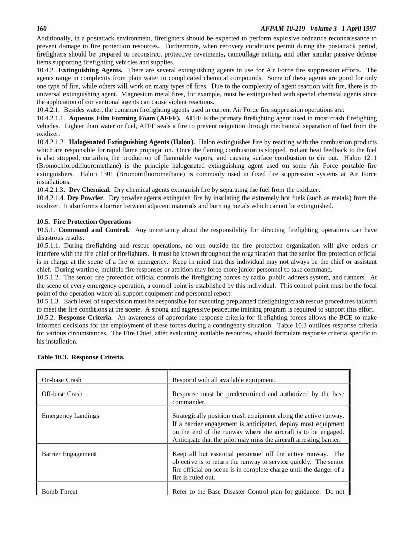
AFPAM 10-219 Volume 3 1 April 1997160
Additionally, in a postattack environment, firefighters should be expected to perform explosive ordnance reconnaissance toprevent damage to fire protection resources. Furthermore, when recovery conditions permit during the postattack period,firefighters should be prepared to reconstruct protective revetments, camouflage netting, and other similar passive defenseitems supporting firefighting vehicles and supplies.10.4.2. Extinguishing Agents. There are several extinguishing agents in use for Air Force fire suppression efforts. Theagents range in complexity from plain water to complicated chemical compounds. Some of these agents are good for onlyone type of fire, while others will work on many types of fires. Due to the complexity of agent reaction with fire, there is nouniversal extinguishing agent. Magnesium metal fires, for example, must be extinguished with special chemical agents sincethe application of conventional agents can cause violent reactions.10.4.2.1. Besides water, the common firefighting agents used in current Air Force fire suppression operations are:10.4.2.1.1. Aqueous Film Forming Foam (AFFF). AFFF is the primary firefighting agent used in most crash firefightingvehicles. Lighter than water or fuel, AFFF seals a fire to prevent reignition through mechanical separation of fuel from theoxidizer.10.4.2.1.2. Halogenated Extinguishing Agents (Halon). Halon extinguishes fire by reacting with the combustion productswhich are responsible for rapid flame propagation. Once the flaming combustion is stopped, radiant heat feedback to the fuelis also stopped, curtailing the production of flammable vapors, and causing surface combustion to die out. Halon 1211(Bromochlorodifluoromethane) is the principle halogenated extinguishing agent used on some Air Force portable fireextinguishers. Halon 1301 (Bromotrifluoromethane) is commonly used in fixed fire suppression systems at Air Forceinstallations.10.4.2.1.3. Dry Chemical. Dry chemical agents extinguish fire by separating the fuel from the oxidizer.10.4.2.1.4. Dry Powder. Dry powder agents extinguish fire by insulating the extremely hot fuels (such as metals) from theoxidizer. It also forms a barrier between adjacent materials and burning metals which cannot be extinguished.
10.5. Fire Protection Operations10.5.1. Command and Control. Any uncertainty about the responsibility for directing firefighting operations can havedisastrous results.10.5.1.1. During firefighting and rescue operations, no one outside the fire protection organization will give orders orinterfere with the fire chief or firefighters. It must be known throughout the organization that the senior fire protection officialis in charge at the scene of a fire or emergency. Keep in mind that this individual may not always be the chief or assistantchief. During wartime, multiple fire responses or attrition may force more junior personnel to take command.10.5.1.2. The senior fire protection official controls the firefighting forces by radio, public address system, and runners. Atthe scene of every emergency operation, a control point is established by this individual. This control point must be the focalpoint of the operation where all support equipment and personnel report.10.5.1.3. Each level of supervision must be responsible for executing preplanned firefighting/crash rescue procedures tailoredto meet the fire conditions at the scene. A strong and aggressive peacetime training program is required to support this effort.10.5.2. Response Criteria. An awareness of appropriate response criteria for firefighting forces allows the BCE to makeinformed decisions for the employment of these forces during a contingency situation. Table 10.3 outlines response criteriafor various circumstances. The Fire Chief, after evaluating available resources, should formulate response criteria specific tohis installation.
Table 10.3. Response Criteria.
On-base Crash Respond with all available equipment.
Off-base Crash Response must be predetermined and authorized by the basecommander.
Emergency Landings Strategically position crash equipment along the active runway.If a barrier engagement is anticipated, deploy most equipmenton the end of the runway where the aircraft is to be engaged.Anticipate that the pilot may miss the aircraft arresting barrier.
Barrier Engagement Keep all but essential personnel off the active runway. Theobjective is to return the runway to service quickly. The seniorfire official on-scene is in complete charge until the danger of afire is ruled out.
Bomb Threat Refer to the Base Disaster Control plan for guidance. Do not

AFPAM 10-219 Volume 3 1 April 1997 161
permit firefighters to search for explosives. Hold firefightersready for first aid, and fire control if the explosive detonates.
Corker Incidents Ensure that fire department has a listing of all aircraft, bothhome station and deployed, that contain corker.
Contain any carbon/graphite materials by using AFFFextinguishing agents.
If necessary, cover any aircraft parked downwind.
Close windows and doors on buildings.
Close filters on critical buildings until the area is cleared.
Make allowances for the fact that these incidents can causedisruption of electronic service.
Promptly evacuate firefighters and other personnel from thearea after the fire is extinguished.
Anticipate that decontamination may be necessary, including:vacuuming of air intakes and surfaces of neighboring aircraft,buildings, and equipment; washing down aircraft andequipment close to the mishap; and vacuuming or washing theclothing of response teams.
Ejection seats, guns, and munitions should be rendered safe byEOD personnel.
Know that burial of the wreckage at a suitable site is a civilengineer responsibility.
Riots/Terrorist Actions/Enemy Attacks
Do not place firefighters or equipment in undue hazard.Require security police for fire vehicles responding to unsecureareas.
Consider installing screened windows and protective plating onfire vehicles.
Enforce strict security of the fire station. Post armed guard, ifnecessary. Allow no one to enter the fire station without thefire chief’s permission.
Chemical Attack Respond only after the nature of the hazard has beendetermined and when a specific response has been directed bythe base commander. If response is initiated, ensure that allfirefighting personnel are clothed in the protective chemicalensemble.
10.5.3. Movement of Crash Vehicles.10.5.3.1. The movement of large firefighting vehicles to the site of an emergency can present several unforeseen difficulties.The size and weight of these vehicles limits airlift capabilities, e.g., the P-15 is not air transportable. Certain other vehiclesmay only fit in larger transport aircraft or may have to be partially disassembled to fit a C-130 for intratheater lift.10.5.3.2. Long distance, over-the-road movement should not be attempted unless there is no alternative (ship, rail, landhaul orair). Most of the larger fire vehicles, such as the P-4 or P-15, are not designed to be driven for long distances. An illustrationof the results of long distance movements occurred during one of the Team Spirit exercises in Korea. A decision was made to

AFPAM 10-219 Volume 3 1 April 1997162
drive a P-4 and a P-2 from Kwang Ju to Osan, a distance of less than 200 miles. En route both vehicles lost their driveengines, taking them out of service for 6 months. If the situation demands that these type vehicles be driven over-the-road,conduct a reconnaissance to determine allowable bridge loadings, tunnel dimensions, clearances of utility crossings, roadwidths, grades, and surface roughness of the proposed route.10.5.4. Airfield Fire Suppression. Airfield fire suppression is a primary concern during disasters and enemy attacks.Airfield operations contain many potential ignition points in the form of fuel-filled aircraft, POL distribution points, andexplosive munitions. Rapid response to any of these "hot spots" can mean the difference between a contained blaze and atowering, uncontrollable inferno.10.5.4.1. Response Time. The prepositioning criteria for potential airfield crash and fire situations was outlined in thesection on response criteria. Maximum crash fire rescue response time requirements for the first arriving major firefightingvehicles are:10.5.4.1.1. One minute to any incident on the runways or overruns after prepositioning for an announced emergency.10.5.4.1.2. Three minutes to any incident on the runways or overruns for an unannounced emergency.10.5.4.2. Response Procedures. While specific firefighting techniques are detailed in the appropriate technical manuals,response procedures depend on the nature of the contingency. The BCE should assist fire department operations by keepingthe fire chief abreast of all unusual activities which may impact fire suppression requirements. For example, duringcontingencies that involve deployments of aircraft from other locations, it is essential that fire department personnel be awareof types, numbers, and locations of additional aircraft that have arrived. These data are normally available from the aircraftmaintenance personnel. Refueling locations, munitions loading areas, types and hazards of munitions, and munitions routesmust be reported to the fire department.10.5.4.2.1. In responding to an airfield fire involving an aircraft crash, it is essential to know the aircraft’s fuel quantity,weapons, cargo, and number of occupants. This information will be passed to the controlling agency when the aircraftdeclares an emergency. The controlling agency then relays relevant information to the fire department. Using this data, firestation personnel can refer to appropriate technical documents regarding munitions, fuel, or hazardous cargo, and are thenable to provide this information via radio to on-scene firefighting personnel.10.5.4.2.2. Information relayed from the flight crew can be extremely valuable to firefighting personnel at the scene of acrash. Knowing the number of persons on board, rescue personnel will not waste valuable time searching for additionalsurvivors once the reported number of persons are accounted for. The aircraft fuel quantity will allow the firefighters toestimate the size of a potential fire. If the aircraft is carrying conventional weapons, T.O. 11A-1-46 can be used by fireprotection personnel for guidance on all types of conventional weapons and munitions. This T.O., used in conjunction withAFMAN 91-201, Explosive Safety Standards, provides the firefighter with adequate knowledge to effectively controlconventional munitions hazards. These publications provide vital information concerning special hazards upon explosion(ejection of fuses, bomblets, missiles, etc.), chemical hazards, net explosive weights, types of protective clothing required, firesymbols, and safe withdrawal distances. Table 10.4 provides an example of data that can be found in the aforementionedpublications.
Table 10.4. Safe Withdrawal Distances.
ITEM
TIME TO
WITHDRAW* DISTANCE**
Conventional Bomb 2-4 min. 2,000 ft - take cover
Cluster Bomb Unit 2-5 min. 2,000 ft - take cover. (Will ejectbomblets up to 1,000 ft with explosivehazards up to 2,000 ft.)
Rockets and Missiles (Propulsion ofthe missile or rocket is primaryhazard. Never approach missile fromfront or rear.)
45 sec. to2 min.
2,000 ft - take cover
* Depends upon core thickness, type of explosive or propellant and environmental conditions.** Never re-enter until cleared by EOD.

AFPAM 10-219 Volume 3 1 April 1997 163
10.5.4.2.3. If the aircraft involved in the crash is carrying nuclear weapons, T.O. 11N-20-11 provides firefighting guidance.A major difference between firefighting operations involving nuclear weapons and those involving conventional munitions isthe radiation hazard. There is no danger of nuclear detonation, but the high explosive component of the weapon may detonatewhen engulfed in fire which can rupture the bomb and release radioactive contamination.10.5.4.3. Use of Prefire Plans. Prefire plans are developed for individual types of aircraft prior to an emergency usingAFTO Form 88, Aircraft Prefire Plan. When aircraft crashes or fires occur during contingency situations, the use of theseplans is highly recommended. The prefire plans provide uniform and chronologically assembled aircraft crash or rescueinformation which can be crucial during airfield fire suppression operations. A current copy of aircraft prefire plans shouldbe carried on the fire chief’s vehicle, assistant chief’s vehicle, and rescue vehicle. This information is also maintained in thealarm communications center and can be transmitted via radio whenever needed. During contingency operations whenadditional aircraft may be deployed into the base, firefighting supervisory personnel must ensure that appropriate prefire plansare prepared for the types of aircraft upon their arrival.10.5.5. Structural Fire Suppression. The suppression of air base structural fires during and following a disaster or enemyattack can be a massive effort. Depending upon the situation, structural fires may be concentrated at one location or widelydispersed throughout the air base. For example, an accidental fire caused by individual carelessness may be limited to asingle structure. On the other hand, an enemy attack could leave a POL facility engulfed in flames on one side of the base,aircraft maintenance hangars burning in the center of the base, and base housing units ablaze on the opposite side of the base.The presence of numerous, widely dispersed fires calls for prompt decisions on the part of the BCE to assist the fire chief inthe effective application of firefighting resources.10.5.5.1. Response Time. Response time guidance is provided to assist the BCE in determining how firefighting assets maybest be employed. These response times may be valid only during limited emergencies. A large scale contingency may taxfirefighting resources to the extent that response times (table 10.5) will have to be adjusted. In fact, changing facility priorityconsiderations during major emergencies may cause abandonment of pre-established response times.
Table 10.5. Structural Fire Suppression Response Times.
ACTIVITY RESPONSE TIME (MINUTES)
Operational, industrial, technical, warehousing, hospital.
Administrative, training, community, commercial,dormitory, BOQ, VOQ, multi-family houses.
Individual or duplex family housing (compact built area),trailer courts.
Isolated single unit family housing, incidental structures,other remote facilities.
5
7
9
15
10.5.5.2. Response Procedures. Procedures for responding to structural fires, similar to those for aircraft fires, are outlinedin appropriate technical orders and are taught in various phases of the firefighter’s training. The BCE is not normally involvedin selecting specific procedures to deal with a given structural fire situation, but must be familiar with the general conceptswhen making decisions concerning the employment of firefighting assets. The BCE can assist the fire chief in overcomingstructural fires in several ways. Facility priority changes that occur as a result of the emergency should be immediatelyreported to the fire chief to prevent misallocation of resources. Coordination should be provided between repair crews andfirefighters to ensure that hazards are reduced by proper utility isolation at the burning structure. If the fire resulted from anenemy attack, the BCE should be prepared to allocate EOD personnel to render unexploded ordnance safe. The BCE canfurther assist the fire chief by authorizing reassignment of firefighting resources from fires at less critical structures to higherpriority areas.10.5.5.3. Use of Prefire Plans. Facility prefire plans should have been developed to assist firefighters during emergencies.A properly prepared AF Form 1028, Facility Prefire Plan, (or similar automated product) contains specific information aboutthe facility. A single line graphic drawing with the proper identifying symbols is attached to each Form 1028. This facilitysketch should show the facility floor plan, facility size, access doors, utility shutoffs, fire hydrants, locations of specialhazards, and any other information useful during firefighting operations. Facility prefire plans are normally available forthese structures.

AFPAM 10-219 Volume 3 1 April 1997164
• Mission essential facilities (identified in base contingency response plan).• Missile sites, rocket pads, and launch control facilities.• Facilities with installed fire suppression systems.• Multi-story facilities.• Hospitals.• Places of public assembly and recreation.• Nurseries, day care centers, and schools.• Other facilities as determined by the fire chief.10.5.6. Special Considerations for Contingency Operations.10.5.6.1. Contingency operations place great demands on the firefighting Prime BEEF teams that deploy, as well as thefirefighters remaining at home station to continue the fire protection effort. In essence, firefighting operations during acontingency situation will be characterized by:• Limited manpower at both the CONUS and theater locations.• Greatly increased fire protection support requirements at overseas and the CONUS locations.• Some routine services being discontinued at existing bases or not established at new bases.• Shortages of water and extinguishing agents.• Shortages in desired numbers and types of firefighting vehicles.• Extended working hours/shift requirements.• Environmental constraints that may restrict firefighting operations to providing only control and containment.• Overseas fire department facilities of a lower standard or capability than normal CONUS facilities.10.5.6.2. During non-emergency conditions, firefighting personnel have several primary functions. They may serve as rescuepersons, crash vehicle operators, structural pumper crew members, alarm room operators, maintenance technicians, fireinspectors, or trainers. During contingency or wartime operations, the primary duties will be crash firefighting and rescueoperations. Although these skills should be maintained by all firefighters, it is realistic to assume that some individuals willbe more proficient than others. The fire chief, both at overseas beddown locations and at CONUS bases, must take thesediffering levels of ability into account when developing shifts and assigning responsibilities.10.5.6.3. Prime BEEF firefighters who will deploy to theater locations should anticipate that they may encounter unfamiliarequipment. There will be different water distribution systems, foreign manufactured firefighting and rescue equipment, and insome situations, a language barrier to be encountered when trying to communicate with fellow firefighters of the host country.Veteran firefighters, having served prolonged periods at theater locations, should conduct informal training sessions for otherteam members who are unfamiliar with theater firefighting/ rescue equipment. Such an effort, particularly when encouragedby the CONUS BCE, will pay dividends when Prime BEEF firefighters join a theater fire department at the deployment site.The "break-in" period will be shortened, and deployed personnel will find it easier to adapt, and through their priorfamiliarization, be more confident in using foreign firefighting equipment.10.5.7. Fire Protection Communications.10.5.7.1. The chaotic conditions which prevail during most emergencies make it imperative that the communication system iswell designed to provide:• An alarm communications center staffed with qualified operators.• Immediate transmission of notifications of fire.• Prompt dispatch of the proper emergency forces.• Notification of supporting activities.• Operational communications between elements of the emergency force and supporting activities at the emergency scene.10.5.7.2. During a contingency all elements of the fire protection communication system must function as a unit.Communications must be maintained between the fire department and the survival recovery center and damage control centerto guarantee that the fire suppression effort is integrated into the total base recovery effort. There must also be a means forcommunication among various firefighting and rescue teams. Another crucial element of the fire protection communicationsystem is a central alarm network capable of alerting fire station personnel of fires at various locations around the air base.These many communication requirements are met by a combination of fixed wire and radio systems. A review of the majorelements will serve to illustrate the inherent need for a well conceived fire protection communications network.10.5.7.2.1. Fire Alarm Communications Center. This center is the "heart" of the fire protection communication system.Staffed around the clock by qualified personnel, the center should possess the necessary equipment to communicate with allelements of the fire protection organization. The requirements of such a facility vary with the installation and in austerelocations it may not be possible to satisfy each requirement. Nevertheless, every effort should be made to provide thefollowing communications capabilities:10.5.7.2.1.1. Fire Crash Radio Net. The fire crash radio net is intended to provide a radio network with discretefrequencies limited to fire stations, firefighting vehicles, EOD, control tower, command post, and the BCE. This systemprovides a radio network for fire suppression and rescue communications which will not be interrupted by other users.

AFPAM 10-219 Volume 3 1 April 1997 165
10.5.7.2.1.2. Reserved Emergency Fire Reporting Phone. This system provides lines from the base telephone exchangewhich are reserved exclusively for transmitting emergency fire alarms. The numbers 117 or 911 have been adopted asstandard throughout the Air Force for this purpose.10.5.7.2.1.3. Primary and Secondary Fixed Wire Operational Crash Alarm. This system provides crash alert to the firedepartment and other selected agencies.10.5.7.2.1.4. Direct Communications Line. This is a "hot line" providing immediate access to the command post, air trafficcontrol tower, aircraft maintenance control, base operations, and other agencies as determined by the fire chief.10.5.7.2.1.5. Central Alarm Receiver. This system provides the capability to receive an alarm signal from all installedfacility fire detection and suppression systems. Fire detection and sprinkler systems connected to central alarm receiver relayan alarm to the communications center when activated by a fire.10.5.7.2.1.6. Voice Recorder. A voice recorder is interconnected to all emergency communication equipment providing arecord of emergency calls. All emergency communications must be recorded and the tapes kept until any resulting fireinvestigation is complete. Normally the tapes are kept for 15 days, unless required for special investigations.10.5.7.2.1.7. Routine Administrative Phones. These call director-type telephones are used by the fire alarmcommunications center to conduct normal administrative business.10.5.7.2.2. Field Operations Portable Communications. Portable field-type communications for emergency fire protectionand crash rescue forces may be grouped into the following categories:10.5.7.2.2.1. Ground-to-ground. Remote, foot-party operations in areas inaccessible to vehicular equipment require short-range, portable, ground-to-ground communications. Two-way portable radios normally satisfy this requirement.10.5.7.2.2.2. On-scene Directional Communications. The fire ground command post must communicate with firefightingforces inside structures or beyond visual or audible voice range to exercise supervisory control of the fire situation. Thiscontact can be maintained by remote voice transmitting devices, portable and fixed mobile loud-hailers, public addresssystems, or two-way portable radios.10.5.7.2.2.3. Emergency Withdrawal Alarm. Fire suppression and rescue efforts frequently involve time limits after whichrapid evacuation becomes imperative. For example, in fires involving explosives, firefighters may only have a limited time tocontrol the blaze before the risk of explosion becomes imminent. For such situations, there must be an audible signalingdevice to warn fire personnel to withdraw from the danger area. Repeated sounding of a siren or other warning device is thebasic signal for emergency withdrawal.
10.6. Auxiliary Firefighting. In a conventional wartime environment, it is very plausible the primary firefighters and theirvehicles and equipment could be totally engaged in mission priority crash rescue and fire suppression tasks involving aircraftand weapons systems. In such situations, lesser priority requirements, such as structural fires, will have to be left unattended.To prevent or at least limit the possibility of damage to essential civil engineer base recovery assets if such a situation shouldarise, each Prime BEEF team should have its own limited internal firefighting capability. To this end, all non-fire protection(non-AFSC 3E7X1) team members must be taught basic firefighting skills that can be used in the very early stages of a fire.Employment of these skills, however, must not constitute a safety hazard to the Prime BEEF team members. At base level itis incumbent upon the fire chief to ensure that such contingency related training is provided at the proper scope and depth toall non-fire protection engineering personnel. The International Fire Service Training Association "Essentials of FireFighting" can serve as a training guide. In most instances, the lack of technical knowledge, protective clothing, and breathingapparatus will limit the auxiliary firefighters role to that of preventing the spread of an existing fire. Regardless of the extentof involvement, however, there are two fundamentals that must be met if auxiliary firefighters are to function effectively andsafely. They are understanding the behavior and types of fire and knowing how to correctly use available tools and equipmentin controlling and/or extinguishing a fire.10.6.1. Fire Behavior. The fire triangle (figure 10.2) is the best way of explaining the three elements essential for any fire tooccur--fuel, oxygen, and heat. Fire can be extinguished by removing any one of these three elements. In other words, a firecan be put out by simply reducing the temperature of the fuel below that needed to support combustion, eliminating the sourceof fuel, or withdrawing the oxygen supply.

AFPAM 10-219 Volume 3 1 April 1997166
Figure 10.2. Fire Triangle.
10.6.1.1. Heat. One of the most common methods employed to extinguish a fire is to cool it with water. This approach ispredicated upon reducing the temperatures of the fuel until it does not produce enough vapor to continue burning.10.6.1.2. Fuel. In some instances, it is easier to extinguish a fire by removing its source of fuel, which, for example, is theintent of making fire breaks when there is a forest fire. This approach would also apply where liquid or gaseous fuel isinvolved, particularly when it is being sourced from a pipe line. A good example of this technique took place in Kuwait afterthe 1991 Iraq war when hundreds of oil wells were ablaze. Early in the recovery effort, a number of the fires were quenchedby simply shutting off the flow of crude oil.10.6.1.3. Oxygen. In certain situations, it is more advisable to extinguish a fire by reducing the oxygen concentration. Thiscan be accomplished by introducing an inert gas (such as Halon) or by separating the oxygen from the fuel. Many fireextinguishers work on this principle.10.6.2. Types of Fires. All fires fall into one of three categories or types: those involving ordinary combustible materials;ones sourced from flammable liquids, greases and gases; and fires involving energized electrical equipment.10.6.2.1. Ordinary Combustible Materials. The preferred method for extinguishing fires involving ordinary combustionmaterials involves using water to reduce the temperature of the burning material (fuel) below its ignition temperature.10.6.2.2. Flammable Liquids, Greases, and Gases. For fires involving flammable liquids, greases and gases, the removalof oxygen or interruption in the chemical chain reaction is the most effective means of extinguishment.10.6.2.3. Energized Electrical Equipment. As a general practice, always deenergize the circuits first before attempting toextinguish a fire involving electrical equipment. Afterwards, treat the remaining flame as a structural or flammable liquid fire,depending upon the fuel that is involved.10.6.3. Fire Extinguishers. The primary use of portable fire extinguishers is as a first line of defense for small fires.Pressurized fire extinguishers can usually be found in most base facilities.10.6.3.1. Portable fire extinguishers are classified according to their intended use on different classes of fires. When usingany extinguisher be sure that it is intended for the type of fire that is being fought.10.6.3.1.1. Class "A" Fires: involves ordinary combustibles such as wood, cloth, paper, rubber, plastics, and other commonmaterial that burn easily.10.6.3.1.2. Class "B" Fires: entails flammable liquids such as gasoline, certain oils, grease, tar, oil based paint, lacquer, andflammable gas.10.6.3.1.3. Class "C" Fires: comprises electrical equipment including wiring, fuse boxes, circuit breakers, machinery, andappliances.10.6.3.2. The newer type fire extinguishers have labels that identify which class of fire(s) they are and are not to be used on.Such a label is illustrated in figure 10.3. In this example, the extinguisher can be used on both Class A and B fires; but mustnot be used to fight a Class C (electrical) fire.
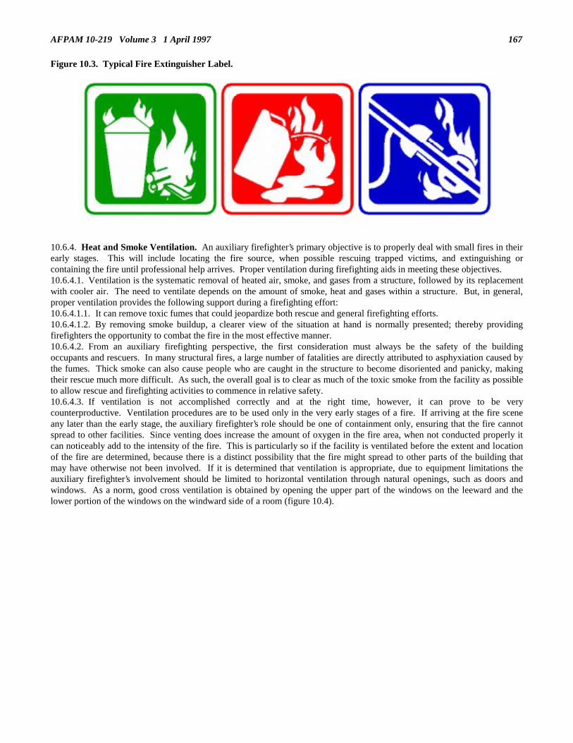
AFPAM 10-219 Volume 3 1 April 1997 167
Figure 10.3. Typical Fire Extinguisher Label.
10.6.4. Heat and Smoke Ventilation. An auxiliary firefighter’s primary objective is to properly deal with small fires in theirearly stages. This will include locating the fire source, when possible rescuing trapped victims, and extinguishing orcontaining the fire until professional help arrives. Proper ventilation during firefighting aids in meeting these objectives.10.6.4.1. Ventilation is the systematic removal of heated air, smoke, and gases from a structure, followed by its replacementwith cooler air. The need to ventilate depends on the amount of smoke, heat and gases within a structure. But, in general,proper ventilation provides the following support during a firefighting effort:10.6.4.1.1. It can remove toxic fumes that could jeopardize both rescue and general firefighting efforts.10.6.4.1.2. By removing smoke buildup, a clearer view of the situation at hand is normally presented; thereby providingfirefighters the opportunity to combat the fire in the most effective manner.10.6.4.2. From an auxiliary firefighting perspective, the first consideration must always be the safety of the buildingoccupants and rescuers. In many structural fires, a large number of fatalities are directly attributed to asphyxiation caused bythe fumes. Thick smoke can also cause people who are caught in the structure to become disoriented and panicky, makingtheir rescue much more difficult. As such, the overall goal is to clear as much of the toxic smoke from the facility as possibleto allow rescue and firefighting activities to commence in relative safety.10.6.4.3. If ventilation is not accomplished correctly and at the right time, however, it can prove to be verycounterproductive. Ventilation procedures are to be used only in the very early stages of a fire. If arriving at the fire sceneany later than the early stage, the auxiliary firefighter’s role should be one of containment only, ensuring that the fire cannotspread to other facilities. Since venting does increase the amount of oxygen in the fire area, when not conducted properly itcan noticeably add to the intensity of the fire. This is particularly so if the facility is ventilated before the extent and locationof the fire are determined, because there is a distinct possibility that the fire might spread to other parts of the building thatmay have otherwise not been involved. If it is determined that ventilation is appropriate, due to equipment limitations theauxiliary firefighter’s involvement should be limited to horizontal ventilation through natural openings, such as doors andwindows. As a norm, good cross ventilation is obtained by opening the upper part of the windows on the leeward and thelower portion of the windows on the windward side of a room (figure 10.4).

AFPAM 10-219 Volume 3 1 April 1997168
Figure 10.4. Proper Venting Procedure.
10.6.5. Firefighting Techniques. The success or failure of an auxiliary firefighting team can in large measure be directlyattributed to the skill and knowledge of the personnel involved. Most fires are controlled in the early stages with immediateand proper application of water. Conversely, fires involving extensive damage are all too often the result of poorly selectedor improperly applied firefighting techniques. A well-trained auxiliary firefighting team, with an attack plan and an adequateamount of water should be able to either extinguish or contain most small fires. However, the need for safety is of utmostimportance. The lack of protective clothing and breathing apparatus make it doubly important for auxiliary firefighters towork in pairs while performing all firefighting operations. In all likelihood, auxiliary firefighting operations will be mostprevalent immediately following an air base attack or natural disaster. In the period between the all clear notification and theassignment of base recovery taskings engineering personnel must survey their immediate areas for local fires, the presence ofunexploded ordnance, the amount of damage sustained, and the status of recovery vehicles, equipment, and supplies. Thosepersonnel that are not required for damage assessment, recovery asset reconnaissance, and local command and control shouldbe prepared to perform auxiliary firefighting tasks until ordered to commence more pressing base recovery efforts. In thisregard it is wise to include a few lengths of hose and a couple of nozzles to your Prime BEEF team kit so your troops willhave a few assets to work with. Supervisory personnel have a dual role during this period. They must ensure needed assetsare not unnecessarily lost due to fires and simultaneously confirm that all necessary actions are taken to ready personnel andequipment for repair and recovery taskings.10.6.5.1. Team Composition and Duties. An auxiliary firefighting team has no set number of personnel. When the needarises, usually every Prime BEEF team member not engaged in other higher priority activities will be used as auxiliaryfirefighters. The ranking person will assume the responsibility of team chief. Team assignments will depend on the numberof firefighters and the mission. However, basic auxiliary firefighter duties include but are not limited to:• Deploying and operating hose lines.• Carrying and operating other tools and equipment.• Performing rescues.• Assisting other team members as required.10.6.5.2. Coordination. A fire attack must be fully coordinated to be successful. Firefighters should follow the team chief’sdirections precisely--deviations could not only be counterproductive but also disastrous. For example, as was brought outearlier, ventilating a fire before its location is identified and hoselines have been made ready may result in expanding the fire.Conversely, when properly performed, ventilation can be a boon to the firefighting effort. In any event, do not lose sight ofthe fact that the auxiliary firefighting role is a very restricted one. With the limited training and access to few professionalfirefighting tools, the auxiliary firefighting role must be confined to only coping with small fires in their earliest stages ofdevelopment.10.6.5.3. Structural Fires. Teams advancing hoselines should not enter a burning building without being instructed to do soby the team chief. Once inside a building, team members must always stay within voice contact of each other at all times.

AFPAM 10-219 Volume 3 1 April 1997 169
The most effective use of water on free burning fires is a direct attack with a solid stream of penetrating fog pattern directed atthe base of the fire (figure 10.5). When using this approach, water should be applied in short bursts. In situations where abuilding cannot be entered and the direct approach cannot be used, an indirect water attack, such as through a window, can beattempted (figure 10.6). With this technique, the hose nozzle setting should range between penetrating and a moderate anglefog and the water stream should be directed at the gases at ceiling level, rather than the base of the fire. In addition, the watershould be played back and forth to ensure good coverage. Once the fire is under control, the hoseline can be advanced toextinguish any remaining hot spots with the direct attack approach discussed previously. When fighting a structural fire, allteam members must be ever watchful for potential hazards such as:• Possible building collapse.• Fire moving in behind, below, or above the hoseline.• Kinks in or obstructions to the hoseline.• Holes or trip hazards.• Hazardous or highly flammable liquids in the area.• Electrical hazards.• Overexertion.
Figure 10.5. Penetrating Fog Technique.

AFPAM 10-219 Volume 3 1 April 1997170
Figure 10.6. Indirect Firefighting Attack.
10.6.5.4. Vehicle Fires. Auxiliary firefighters can also expect to encounter vehicle fires after an attack. The scope of theiractions, however, would be generally limited to smaller, passenger type vehicles rather than large pieces of equipment such astank trucks or tractor trailers. This scope is based on equipment and training limitations. In a small vehicle fire, a fuelignition can usually be extinguished easily by using a portable fire extinguisher. If the fuel tank has been ruptured, a waterfog may be used to put out the fire and keep the fuel tank cool to avoid further combustion. Burning fuel leaking from thevehicle should be flushed clear of the area with water and extinguished with a portable extinguisher or sand. Once the fuelportion of the fire is out, the remaining flames can be handled as a structural fire. At times during vehicle accidents thatinvolve fire, occupants become trapped in the wreck. In such situations, it may be necessary to protect trapped passengersfrom the flames by using water in a fog pattern until they can be rescued by firefighters having the appropriate tools andequipment.10.6.5.5. Fires Involving Utilities. For obvious safety purposes, auxiliary firefighters must be able to isolate the utilitysupply (electricity and gas) to a facility.10.6.5.5.1. Electrical Fires. In a structural fire, from a safety standpoint, power should normally remain on as long aspossible to provide lighting and ventilation for firefighting and rescue operations. When the building becomes damaged tothe point that electrical hazards exist, the power should be immediately shut off by throwing the main switch or disconnectinga fuse at the main service box. Fires in electrical equipment can be handled with relative ease once they are de-energized. Asmentioned earlier, once the power has been eliminated, electrical fires are usually treated in the same fashion as a structuralfire.10.6.5.5.2. Gas Utilities. Facilities with gas utilities should have the gas turned off as soon as possible. The meter and cut-off valve are usually located outside the building. The flow of gas into the building may be stopped by turning the cut-offvalve to the closed position, which will be at a right angle to the pipe, as shown in figure 10.7. Gas fires should not beextinguished until gas flow can be shut off.

AFPAM 10-219 Volume 3 1 April 1997 171
Figure 10.7. Typical Gas Shutoff Valve.
10.6.5.6. Bare Base Fires. The basic principles of firefighting used for modern, built-up air bases also apply to beddownlocations. However, the type of construction and more primitive living conditions of a bare base environment make thepossibility and spread of fire more pronounced. Most tents burn much more readily than standard construction; consequently,a fire is prone to spread at an alarming speed in a tent city. An adequate water supply could also be a problem--a bare basewater system may not be sufficient to support a sustained firefighting effort. By the time that an alternative water source isobtained, the entire compound could be engulfed in flames. The best course of action in a bare base fire may be to simply tryto stop the fire from spreading to unaffected assets. One quick way of accomplishing this is to drop all tentage near the tentthat is on fire. Another effective course of action, assuming water is available, is to hose down the other tents in the area.10.6.5.7. Ground Cover Fires. Ground cover fires include fires in weeds, grass, brush, and similar vegetation. Fighting aground cover fire can be a very dangerous undertaking. Many firefighters have lost their lives or been seriously injured whiletrying to control this type of fire. As with all firefighting efforts, thoroughly consider the situation before implementing acombative tactic, particularly when it is a ground cover fire. Remember, regardless of the firefighting technique beingemployed, always make the safety of personnel a prime concern. Once a ground cover fire starts, it may burn rapidly. Thereare three main factors that affect ground cover fires: types of fuel, weather, and terrain. Attacking a ground fire is based onperimeter control. The control line can be either established at the edge of the fire for a direct attack or at varying distancesfrom the fire to form an indirect attack.10.6.5.7.1. Direct Attack. The direct attack is action taken directly against the flames. If a water source is available, hoselines can be used in conjunction with back pack water extinguishers to extinguish the fire. Hand tools can also be used tothrow soil on the fire, beat the fire out and to cut down or remove fuel in the fire’s potential path.10.6.5.7.2. Indirect Attack. The indirect attack is taken at varying distances from the fire. This method is used when thefire is too hot, too big, or moving too fast to use a direct attack. With this approach, the idea is to stop the fire by removingfuel from its path. This is accomplished by cutting fire breaks with hand tools or heavy equipment (figure 10.8). Natural firebreaks such as roads and streams should also be considered and used when appropriate.

AFPAM 10-219 Volume 3 1 April 1997172
Figure 10.8. Fire Break Operation.
10.6.6. Rescue Techniques. In a postattack environment, with burning and collapsed buildings, downed electrical powerlines, and damaged vehicles, there could be an urgent need for widespread rescue operations. This need must be temperedwith consideration of the personal protection of auxiliary firefighter personnel. Protective gear for use by auxiliaryfirefighters during rescue operations is extremely limited. The basic combat helmet, flak vest, work gloves, and boots used bymost civil engineer personnel will provide some limited measure of protection, but are far from effective against the excessiveheat and toxic gases produced by an intense fire. For this reason, each potential rescue situation must be carefully evaluatedin terms of the probability of making a safe and successful rescue before engineer personnel are committed to such an activity.10.6.6.1. Building Rescues. Probably the most hazardous duty an auxiliary firefighter may have to perform is to rescueindividuals from a burning building. When entering a burning building to perform rescue work, each auxiliary firefightermust first consider personal safety and the safety of team members. As a general rule, a building should not be entered exceptin the very early stages of a fire. If a building is entered, a hose team must always be available to provide water streamprotection for both the rescuer and victim. However, under no conditions should an auxiliary firefighter attempt a rescue in aburning building above the ground floor.10.6.6.1.1. Rescues in Collapsed Buildings. The difficulty in rescuing people from bombed or collapsed structuresdepends to a large degree where they are located. During war, the situation may be further aggravated by the possiblepresence of unexploded ordnance situated in the rubble. Again, unnecessary chances should not be taken. The situation maywell dictate that rescue efforts be limited to helping only those victims that are readily accessible or who are slightly trapped.If such is the case, so be it.10.6.6.1.2. Rescues From Electrical Contact. To reach a victim who is touching electrically energized wires or equipment,an auxiliary firefighter must take every precaution to protect himself and others. It is essential that all electrical wires andconductors be treated as if they were energized. If the wire is not entangled with the victim’s body, a wooden pole with ahook on the end should be used to drag the victim clear of the wire. Under no circumstances should the rescuer allow himselfor his clothing to touch the wire or victim during the rescue operation. Sometimes it is more practical to remove the cablefrom the victim. This can be done by throwing one end of a rope over the line. Both ends of the rope are then tied togetherand the wire is carefully pulled away.10.6.6.1.3. Vehicle Extrications. Vehicle extrication is a complex and demanding task. Auxiliary firefighters must bementally prepared for the psychological trauma of facing victims who are burned, seriously injured, or hysterical. Power toolsnormally available to firefighters for extracting victims from vehicles, such as the power saw shown in figure 10.9, will notusually be available to auxiliary firefighters. As is the case in most rescue operations, safety in a vehicle extrication isessential. If safety is disregarded, both the victim and the rescuer may be placed in further danger. The first action thatshould be accomplished in a vehicle rescue is to stabilize the vehicle. If a vehicle is found on its side or upside down, itshould be stabilized by placing wedge boards, rocks, or other debris under the vehicle. If no material for this purpose isreadily available, improvised methods can be tried such as using bumper jacks and ropes, or opening the trunk and hood.

AFPAM 10-219 Volume 3 1 April 1997 173
After the vehicle is stabilized, the easiest way to enter the vehicle must be chosen. Doors are the first choice. If they arejammed, a window may have to be used. If a window must be broken, start with the rear one. This gives a larger opening andglass will not fall on the victim. The primary objective is to gain access to the victim and stabilize and protect this individualuntil extrication is possible. If the victim is trapped in the vehicle by the steering wheel, seats, or dashboard, stabilize theperson until professional help (medical or fire department personnel) arrives. If the victim is conscious, coherent, and notcompletely entangled in the vehicle, removal operations can start. First, wounds should be bandaged, fractures splinted, andthe body immobilized to reduce the possibility of further injury. Once the victim has been properly prepared for removal, anysharp edges in the vehicle should be covered and the opening through which the victim will be moved should be padded withblankets or similar materials. When removing the victim, travel as smoothly as possible and try to avoid any jerking orsudden movements.
Figure 10.9. Professional Power Rescue Tool.
10.7. Search and Rescue (SAR) Concepts. Search and rescue operations are a crucial function during contingencies.Whether the emergency is a major aircraft accident, a natural disaster, or an enemy attack, there may be scores of injuredpersonnel who must be located, treated, and evacuated. Search and rescue missions must be carried out promptly, by welltrained personnel with the proper equipment, or it is highly probable that disaster casualties will increase dramatically. In theaftermath of a disaster or attack, firefighting and crash rescue personnel, augmented by personnel from other sections of thecivil engineer force, must be constantly ready to participate in search and rescue operations (figure 10.10).

AFPAM 10-219 Volume 3 1 April 1997174
Figure 10.10. Firefighter and Augmentee Performing Rescue.
10.7.1. Civil Engineer Involvement in Search and Rescue. Civil engineers may be involved in search and rescueoperations in several ways. Depending on the type and extent of the emergency, civil engineer search and rescue support mayrange from minimal to very extensive. Firefighters and rescue personnel would undoubtedly be very involved in the rescue ofsurvivors from an aircraft crash or other major accident on the base (figure 10.11), but would provide little, if any, search andrescue support for a group of campers lost in a nearby forest. The rescue of the campers would probably be handled by alocal agency and civil engineers would provide support only if requested and authorized. The following areas outline possiblecivil engineer responses to research and rescue requirements.
Figure 10.11. On-Base Rescue Operation.

AFPAM 10-219 Volume 3 1 April 1997 175
10.7.1.1. Firefighters/Crash Rescue Personnel. The highly trained personnel which serve in the fire department are themost qualified to conduct search and rescue operations. Not only do most of them have first aid training and the skills andequipment to rescue persons trapped as a result of a disaster, but they will always be the first to respond to a major aircraftaccident on the air base. Once at the scene, they will use all of their resources to control fires and extract survivors from theaircraft (figure 10.12).
Figure 10.12. Aircrew Extraction.
10.7.1.2. Augmentees. In a postattack environment, the air base will be faced with numerous fires, extensive damage, andinjured personnel requiring emergency rescue and medical care. Getting to fires and rescue locations will be complicated bythe presence of unexploded ordnance, craters, pavement damage, and scattered debris caused by bombs and other ordnance.Firefighting and rescue must be accomplished with fixed numbers of professional firefighters, equipment, and materials.Attrition can be expected to steadily decrease the availability of professional firefighters, fire vehicles, and rescue capabilities.The fire department will not have the resources to simultaneously respond to and extinguish all these fires, respond to allrescue situations, and support all aircraft incidents. Commanders must decide which fire to fight, which fires to let burn,which people to rescue and which people to leave to buddy care. These and other decisions will affect the launch andrecovery of aircraft, the response to returning battle-damaged aircraft, and the operation of both fixed and mobile aircraftarresting systems. Augmentees may be needed to perform those search and rescue operations that the professional firefightersare unable to attend. Therefore, civil engineer personnel, along with all other combat support forces, must possess the basicknowledge and skills to help save lives and mitigate human suffering (figure 10.13). The severity of the emergency willdictate the number of persons required, but efforts should be made to select individuals with some of the followingqualifications:

AFPAM 10-219 Volume 3 1 April 1997176
Figure 10.13. Augmentees Performing Buddy-Care.
10.7.1.2.1 Good physical condition. The physical demands of the search and rescue operation are likely to be great.10.7.1.2.2. First aid training. Survivors may require immediate first aid to prevent serious complications.10.7.1.2.3. Advanced emergency medical care training.10.7.1.2.4. Specialized rescue equipment experience.10.7.1.2.5. Familiarity with the geography of the search and rescue area.10.7.1.2.6. Knowledge of survivor extrication methods.10.7.1.2.7. Knowledge of area search methods.10.7.2. Site Access Support. Civil engineer heavy equipment and operators skills can be invaluable in clearing access to thesite of a major disaster. When rescue vehicles are unable to reach and remove the survivors of an aircraft crash in a heavilywooded area, civil engineer earth moving equipment can clear a road or create a path to the crash site. Following anearthquake, an engineer crane could be used to remove the fallen beams of a collapsed building, allowing rescuers to reachsurvivors trapped beneath the rubble.10.7.3. Rescue Equipment. The type equipment employed by a SAR team will depend on the type emergency and thelocation of the rescue effort. Medical equipment and supplies are normally carried in fire rescue vehicles or ambulances toaid the injured during an on-base disaster and to an aircraft accident in a remote region. However, if an off-base areaprecludes vehicular travel, the medical supplies must be carried in by SAR personnel or delivered by air. A team going into awilderness area would also require navigational aids, food, water, portable shelters, and other items to operate in aninhospitable environment. The following general categories of equipment should be considered in equipping a SAR team formissions:10.7.3.1. Communications. Portable hand-held or backpack type transceivers should be used for radio communicationsbetween team members, SAR aircraft, and the staging base, when one is established (figure 10.14).

AFPAM 10-219 Volume 3 1 April 1997 177
Figure 10.14. Radio Communications.
10.7.3.2. Navigation Equipment. Detailed maps of the search area showing all terrain features, landmarks, and watersources are a necessity. A global positioning system, reliable compasses or other direction finding equipment are required forrescue operations in remote areas.10.7.3.3. Operational Equipment. Select equipment appropriate for the type SAR operation the team is expected toaccomplish. A SAR operation centered on an area of demolished structures on the base requires crowbars, shovels, rope, andsimilar items to assist in freeing people entrapped in the debris. Conversely, if the operation’s goal is to reach a downedaircraft in a snow covered mountain area, snowshoes, mountaineering equipment, and portable litters should be among theteam’s equipment.10.7.3.4. Food and Water. Food and water will only be carried by teams operating in off-base remote areas. Teams shouldcarry adequate quantities to sustain an operation lasting 48 to 72 hours. If the mission goes beyond these limits, the teamshould be resupplied.10.7.3.5. Photographic Equipment. A simple, reliable camera is needed for missions involving aircraft crashes.Photographic evidence of aircraft wreckage, instrument panels, aircraft controls, and terrain disfigurations is useful foraccident analysis. On-base disasters requiring photography should be provided by base photographers.10.7.3.6. Survivor Extraction Equipment. Metal cutters, ax, knife, body splint, litter, prybar, and a hydraulic rescue kit aretypical items used by the fire department for situations involving extraction of survivors from downed aircraft (figure 10.15).

AFPAM 10-219 Volume 3 1 April 1997178
Figure 10.15. Survivor Extraction Equipment.
10.7.3.7. Loud Hailer. This item is used for coordinating team actions at the rescue scene.10.7.4. Search and Rescue Operations. Search and rescue operations can be limited in scope, involving small searchparties which cover the area on foot (figure 10.16) or a massive effort covering thousands of square miles of land or sea andinvolving ships, aircraft, and personnel of other services and governmental agencies. Engineer SAR operations will generallybe limited to on-base disaster response and, when required, operations support in the local community.

AFPAM 10-219 Volume 3 1 April 1997 179
Figure 10.16. Small Search Party Operation.
10.7.4.1. On-Base Search and Rescue. Probably the most common SAR operation on the air base involves a major aircraftaccident. In such a situation firefighters/rescue personnel are responsible for containing any resulting fire and must promptlyremove survivors from the wreckage. A systematic search of the surrounding area may also be required to locate personsthrown from the wreckage by the impact. In most on-base aircraft accidents the crash site will be defined and team effortswill concentrate on the immediate rescue of personnel rather than search of the surrounding area. Other on-base SARoperations result from earthquake, flood, hurricane, or enemy attack. Under these conditions, several search teams must beassigned to search the air base for survivors. Searches of this type require precise coordination and require that all teams bethoroughly briefed on designated search areas, techniques, rescue procedures, communications protocol, reportingrequirements, and availability of medical support for survivors. The SAR operation must ensure that the entire disaster area iscovered with no duplication of effort which could result in delays in reaching survivors.10.7.4.2. Off-Base Search and Rescue. Civil engineer involvement in off-base SAR efforts will probably be limited toheavy equipment support for access to a disaster site and augmentation of search teams. Civil engineer resources should notparticipate in off-base operations if there is a high probability that they will be needed in base recovery or rescue operations.10.7.4.3. Operations Stage. Regardless of the location of the SAR effort, basic operations are generally the same followingthis sequence:• Receive mission briefing.• Proceed to disaster scene.• Conduct search.• Rescue survivors.• Provide emergency care for survivors.• Transport the injured to a medical facility.10.7.4.4. Search and Rescue Debriefing. The debriefing should occur as soon as the SAR team returns from the search areato determine if the team has information effecting the outcome of the SAR mission. This is particularly important for teamsassigned to a mission still in progress. In addition to providing first-hand information about the results of the SAR mission,the debriefing can supply knowledge of support requirements to other SAR teams and suggestions for improvements to theon-going effort.
10.8. Summary.10.8.1. Fire protection personnel have crucial taskings and responsibilities to perform during post disaster situations. Theseinclude rescue, fire containment, and fire extinguishment. Under wartime conditions fire department organizations may be allmilitary, all civilian, or a military/civilian mix depending upon location. Peacetime training programs must take thesepotential organizational arrangements into account. Fire protection supervisory personnel can expect to face both airfield andstructural fire fighting requirements during the post disaster period. Specific procedures and response times are associated

AFPAM 10-219 Volume 3 1 April 1997180
with both types of requirements and fire protection command and control elements must be familiar with these parameters.Fire protection personnel can also expect to face shortages of supplies and equipment, longer working hours, and austereconditions during wartime, particularly at deployed locations.10.8.2. Because fire protection personnel will be heavily tasked for response to priority facilities and aircraft assetsimmediately following an air base attack, other civil engineer forces must serve as auxiliary firefighters to protect other basefacilities and recovery assets. Auxiliary firefighters must be able to respond to smaller structural, vehicle, and ground coverfires with the intent of stopping such fires in their early stages of development. Auxiliary firefighters must also be capable ofperforming limited personnel rescue activities. Whether accomplishing firefighting or rescue taskings, however, auxiliaryfirefighters must make safety one of their primary considerations.10.8.3. The civil engineer’s primary involvement in search and rescue operations is in response to on-base life-threateningsituations. Fire protection personnel have the major role in this activity. Support of more extensive off-base search andrescue efforts is generally limited to the equipment and personnel necessary to gain access to the search area. Supervisorsshould be aware of the personnel skills and equipment required for the search and rescue effort.

AFPAM 10-219 Volume 3 1 April 1997 181
Chapter 11
OPERATION, MAINTENANCE AND FOLLOW-ON REPAIROF ESSENTIAL SERVICES, FACILITIES AND EQUIPMENT
11.1. Introduction. Expedient repairs are completed, and the threat of continued enemy activity or a recurrence of thenatural phenomenon that caused the disaster is minimal. This is not the time, however, to stop and rest. The BCE must nowshift efforts from the expedient mode to a more deliberate mode of operations and maintenance (O&M) as well as takingaction to facilitate improved repairs. Using information from early damage assessment, follow-on visits to damage locations,and knowledge of the installation mission, a work plan must be developed. This plan defines what work needs to be done andwhen, and suggests methods of accomplishment. Safe, alternate transportation routes must be established, diminishedsupplies must be replenished and remote stockpiling must be considered.
11.2. Overview. Since expedient repairs have been made, the base now shifts to an operations and maintenance mode forcontinued operation. The focus is now on upgrading previous makeshift repairs to allow for extended operations and themaintenance of sustained flying operations.11.2.1. As in the initial recovery phase, identification of required work is essential. This chapter outlines general proceduresfor identifying and documenting follow-on work requirements. Information is also included which outlines civil engineeroptions for accomplishment of this work. This includes a discussion of U.S. Army support of USAF air base repairrequirements. For tasks within the capability of in-house forces, guidance is provided on making repairs which are moredurable and better support the installation’s mission.11.2.2. Later sections of the chapter deal with alternate transportation routes for use during and after emergencies.Maintenance and repair of existing routes is emphasized, with design and construction of new routes covered briefly as a lastresort measure. Finally, resupply of diminished stocks needed for operations, maintenance, and upgrade of repairs isaddressed. Consideration for dispersed stockpiling of materials is also included.
11.3. O&M Considerations11.3.1. Safety. Even though the urgency of the immediate post disaster phase has passed, safety is still a criticalconsideration. Personnel will experience a state of mental and physical exhaustion unlike any other previously experienced.Safety is everyone’s concern, but supervisors should be especially observant and cautious. Watch for signs of excessivefatigue and do not allow your personnel to overextend themselves. Carelessness usually accompanies fatigue. Shortcutstaken when people are tired and not thinking clearly can have disastrous results.11.3.2. U.S. Army/U.S. Air Force Repair Responsibilities. If the BCE is to make the most effective use of all resourcesduring the follow-on damage repair period, a complete understanding of agreements between U.S. Army and Air Force unitsregarding the degree of support which will be provided on these occasions is important. U.S. Army and Air Forceresponsibilities as outlined in AFJI 10-218, Troop Construction and Engineering Support of the Air Force Overseas, aredetailed in the following paragraphs.11.3.2.1. The Army will provide military troop construction to the Air Force overseas. It will ensure that required units areequipped, manned, and trained to support Air Force needs. This support is to:• Assist in emergency repair of war damaged air bases exceeding Air Force engineer organic capability.• Repair and restore air bases damaged beyond emergency repair.• Assist in force beddown exceeding Air Force engineer organic capability.• Develop bases to include acquisition, improvement, replacement, construction, and expansion of terrain and facilities.• Manage repair and restoration of war damage and base development, including supervising Army personnel. The Air
Force base commander sets the priorities.• Develop engineering designs, plans, and materials to meet Air Force needs.• Ensure security during construction, including ground defense beyond air base security of the Air Force.• Supply construction materials and equipment not provided by the Air Force.11.3.2.2. The Air Force will provide military troop engineer support from its resources. It will ensure that the units areequipped, manned, and trained adequately to support its needs. This support includes:• Emergency repair of war damage to air bases.• Force beddown of units and weapons systems, excluding Army base development responsibilities.• Operation and maintenance of facilities and installations.• Crash rescue and fire suppression.• Management of emergency repair of war damage and force beddown.• Supply of material and equipment to perform its engineering mission.

AFPAM 10-219 Volume 3 1 April 1997182
• Command and control of Air Force engineer units.11.3.2.3. The responsible Army commander will command all Army troop units. Command and control relationships will beestablished to ensure the accomplishment of the airfield damage repair missions. Normally, this relationship will be generalor direct support of a specific air base. When a number of air bases are concerned and limited engineer resources areavailable, a priority of support must be established. It is essential that the Army commander retain the flexibility to shiftengineer resources to concentrate efforts in airfield damage repair and other support missions.11.3.2.4. Regardless of the support responsibilities outlined above, the BCE will probably be facing a situation where repairrequirements will far outstrip manpower availability. The need to use to the fullest those forces that are available isparamount. Army engineer units are generally equipped for heavy horizontal construction, therefore, they should be usedwhere this capability is most required. Typical Army engineer postdisaster taskings would include major critical facilityrestoration, construction of concrete airfield pavements, and rebuild of electrical distribution substations. Most Air Forceengineer units, on the other hand, are limited to light construction and repair by the nature of their training and equipage.They are, however, quite capable of accomplishing critical repair taskings such as replacing substantial portions of utilitydistribution systems, constructing temporary access routes, partitioning and restoring utility support to major facilities, andperforming debris clearance and demolition. The main point is the BCE must use all engineering resources to their maximumpotential in the postdisaster environment and not get hung up on the technicalities of written responsibilities.11.3.3. The Operations and Maintenance Concept. The concept of operations and maintenance is a process foraccomplishing work. It is a familiar theme for Air Force civil engineer units in that their peacetime responsibilities arecentered around the procedures and requirements associated with O&M taskings. Many similarities exist in the operationsand maintenance concepts for both peacetime and wartime or contingency postdisaster situations; however, severaldifferences are also present. We will look at these differences as the steps for accomplishing O&M work are discussed.11.3.3.1. Concept Steps. For the purpose of this discussion the operations and maintenance concept will be addressed in sixbasic steps.• Step 1. Identify the work that needs to be done.• Step 2. Estimate the work requirements. Each job must be quantified in terms of man-hours, materials and equipment
necessary.• Step 3. Assign work priorities. These priorities will aid in developing a work strategy.• Step 4. Develop a work plan or strategy capable of sustaining the sortie rate necessary for combat operations.• Step 5. Assemble resources. Action must be taken to acquire the resources estimated in Step 2.• Step 6. Accomplish the work. The final and most important step is to complete the work identified.11.3.3.2. Work Identification (Step 1). Since the emphasis of this chapter is on operations and maintenance during therecovery phase, we will address a more deliberate postdisaster process. As you recall from chapter 6, damage assessmentteams (DATs) and damage assessment and response teams (DARTs) were dispatched during the initial recovery phase toidentify and quantify damage. Due to the urgency of immediate postdisaster repair response, assessments were necessarilylimited to those requirements which most impacted launch and recovery of combat mission aircraft. Some damages wererepaired during this initial recovery period using expedient methods, others were isolated, and others were ignored. In thepostdisaster O&M period, it is time to identify all repair requirements, irrespective of scope and importance to the primary airbase combat mission. Expedient repairs must be replaced with permanent fixes, isolated utilities should be reinstated, andproblem areas that were originally put aside must be corrected. Regardless of what repair actions were taken during theimmediate postdisaster period, all follow-on work must be identified in enough detail to convey the specific requirements ofthe job. For example, a general statement of work to repair the electrical service to a building is not enough information toallow a repair crew to effectively accomplish the job. Details such as replace 25 kVA transformer and replace the servicedrop to the facility must be provided. A detailed description of work will ease detailed estimating and possibly save valuablerepair time. Personnel chosen to perform the work identification should also be capable of determining, at least in apreliminary sense, how the work will be accomplished, i.e., by in-house forces, by contract, by Army engineers, etc. This willaid in the performance of the next step, work estimating, in that different levels of detail are required for the different methodsof accomplishment.11.3.3.3. Estimate Work (Step 2). As stated before, a detailed description of the work requirements will ease workestimations. Estimating work is quantifying work in terms of the manpower, materials, and special equipment required. Forin-house work rough manhour estimates are provided for each craft required on a particular repair. Materials are specified bydescription, quantity and, if in stock, by the stock location. Special equipment should be addressed, particularly if itsrequirement is not made obvious by reading the work description. This is most helpful when equipment must be rented oracquired from another agency. For non-in-house work, initial estimating must be of sufficient scope to allow contractprogrammers to produce costing and programming documents. Major command headquarters must also be informed of thefiscal requirements and work scopes so contract monies and inter-service support can be obtained.11.3.3.4. Assign Work Priority (Step 3). At this stage of the postdisaster recovery effort, the assignment of work prioritiesis crucial to generating and maintaining a sortie rate adequate to sustain the combat mission. Similarly, prudent appropriationof available manpower and resources is the key to the expeditious recovery of the base and the resumption of the full flying

AFPAM 10-219 Volume 3 1 April 1997 183
mission. All work will fall into one of the categories used for peacetime O&M purposes. As compared to peacetimeoperations, however, you will probably find that more priority ones and twos will be identified since facility, utility andairfield pavement damages will cause many mission hindrances, safety hazards, and perhaps even health hazards. Expect tosee work that is normally a low priority in peacetime become a higher priority in the postdisaster period. Drainage work is aprime example. In peacetime such activity is usually a routine maintenance function but in the postdisaster environment, ifflightline area flooding is caused by drainage system blockage, repairs will rapidly become critical. Also be sure to maintaina combat mission mindset when assigning work priorities. What are considered safety deficiencies in peacetime may well beacceptable risks in the postdisaster period. Furthermore, be wary of assigning too high a priority to quality of life features atthe expense of direct mission support requirements. The pressure will be on to do this and you will need to maintain abalanced perspective. The following work priorities will be used in the post disaster timeframe:• Priority I. Work done in direct support of the mission.• Priority II. Work done to provide adequate security or to eliminate hazards.• Priority III. Work done to prevent a breakdown of essential operations and services.• Priority IV. Work not qualifying for a higher priority.11.3.3.5. Develop a Work Plan (Step 4). Now that the first three steps in the preparation phase are completed the transitionfrom preparation to execution can begin. So far the requirements have been identified, labor and materials estimated, and arough priority listing established. Now the task calls for arranging the work by order of importance and making the finaldetermination of how it is to be accomplished (in-house or otherwise). Several factors influence the development of apostdisaster work plan and many of them interact with each other. Only after each of these factors has been considered can awork plan be deemed complete.11.3.3.5.1. Scope of Work. The scope of the identified work requirements must be closely considered to precludeoverloading various trades. Such action causes a bottleneck in task accomplishment and subsequent slippages in workcompletions. Look closely at contract support for tasks that are large in scope, require unique skills or expertise not normallyavailable in a typical military engineer unit, or require many manhours of a particular trade as compared to others.11.3.3.5.2. Material Availability. To a large extent the availability of materials will determine which of the highest prioritytasks will be performed first. Maximize use of whatever special levels and war reserve materiels are remaining; contingencyand wartime situations are what they are there for. Materials being held for peacetime O&M requirements are also anothersource of supply support. Cannibalization from lower priority damaged facilities or utilities should likewise be considered,particularly for items which traditionally have long lead times. Put higher priority systems back into full service this way andlet lower priority systems wait for the supply system to provide the necessary materials. Do not overlook the value of localpurchase for repair materials. In many cases much of an engineer unit’s peacetime supply overseas comes from local sources.Any standing contracts or purchase orders from local vendors should be "plussed-up" to obtain as much material as possible.11.3.3.5.3. Manpower Availability. The majority of postdisaster O&M actions will be accomplished by in-house forcessimply due to their immediate availability. If engineer units from other Services are in-place, however, they should beincorporated into the postdisaster O&M work strategy as well. Use these units wisely. Assign major restoration tasksassociated with critical facility and utility requirements to these units. Do not waste their talents on low priority jobs or tasksthat do not utilize their full engineering capability. At some locations the local economy may be able to furnish contractorsupport for O&M requirements. Work with base contracting personnel to line this support up for tasks that do not require adetailed design effort. Another avenue of manpower support that should be investigated is that of local civilian overhires.Historically, much of the civil engineer’s wartime and contingency labor support has come from this source. Not only will in-house skilled personnel be freed up for more technical tasks, but the potential also exists for adding additional semi-skilledpersonnel to the O&M workforce. Lastly, remember that some of your workforce will be required to provide day-to-dayoperations support and will not be fully available for repair taskings. Account for this in your planning but do not overmanthis area--go with a minimum manning concept.11.3.3.5.4. Timing Constraints. Postdisaster O&M efforts will be greatly affected by timing constraints which, in turn, steerthe development of the overall work schedule. Mission support is the driver for work scheduling and all activities should beaimed at satisfying these taskings first. Use the multi-skilling features of in-house forces to advantage, e.g., do not let acritical POL repair project slip due to shortages in the liquid fuels maintenance trade--use utility systems personnel toaugment. Additionally, do not be hesitant to mix in-house forces with contractors or other engineering units. Work yourmanpower assets together toward a common goal of bringing the most critical portions of the base back up to standard.11.3.3.5.5. Funds Availability. Keep your major command informed on your funding requirements for supply, civilian pay,and contract support. To some extent each base can keep the supply lines flowing by reallocation of local O&M funds, butfew bases will have the ability to fund any sizable contract support or civilian pay increases. As postdisaster O&M effortsprogress, the need for additional funding will increase since requirements will become more defined.11.3.3.6. Assemble Resources (Step 5). Gathering of work materials and equipment and assigning manpower to the varioustasks are the first steps in the execution phase of the postdisaster O&M effort. Follow your work plan priorities as closely aspossible and exploit the various avenues of supply and manpower support mentioned earlier to build your O&M capability.11.3.3.7. Accomplish Work (Step 6). Accomplishing the work is the final and most important step in the execution phase

AFPAM 10-219 Volume 3 1 April 1997184
and the O&M concept. This final step brings civil engineers closer to fully recovering the installation and sustaining theflying mission. As more and more repairs are made to base facilities and utilities, be prepared to transition an increasedportion of your work force to an operations mode.
11.4. Airfield Ancillary Equipment O&M. Operations and maintenance of ancillary airfield equipment are critical to theoperation of the airfield. Items such as aircraft arresting systems, airfield lighting, and navigational aids, which wereexpediently repaired immediately following the emergency, must now be maintained to support continuing aircraft operations.Any upgrade repairs that can be made to these systems without degrading the operational capability of the air base should beattempted at this time.11.4.1. Aircraft Arresting Systems.11.4.1.1. In a wartime situation where only a minimum operating strip has been made available for aircraft launch andrecovery, a mobile aircraft arresting system has most likely been installed. Routine servicing and inspection of the systemmust be maintained throughout its period of use. In all likelihood, however, once the threat of reattack is over, efforts willintensify to bring the full runway surface back into operation. This, in turn, will permit permanently installed arrestingbarriers to be reinstated into service. Once such permanent barriers are put into use, servicing and inspection efforts shouldbe devoted to these systems. The mobile system then should be removed, reconditioned as necessary, and placed back intostandby storage.11.4.1.2. In the event that airfield damages were such that the permanently installed systems could still be used during thepostdisaster period, particular attention must be paid to any expedient repairs that were made on the systems. All repairsmade by substitution must be identified. A listing of the materials required to restore the system to full operational capabilityand alleviate the parts substitution condition should be developed. These materials should be immediately ordered andinstalled once they are received. Additionally, any stockpiled replacement parts which were expended during repair effortsshould also be replenished. Repairs beyond component replacement are usually beyond the capability of the in-house workforce and should be identified to the parent major command so that appropriate repair support can be arranged.11.4.2. Airfield Lighting System.11.4.2.1. As was the case with the mobile aircraft arresting system, if a minimum operating strip was established, a mobileairfield lighting system was probably installed to support night and adverse weather flying requirements. A daily inspectionof such a system is mandatory. As repairs to runway pavement surfaces are being made, concurrent repairs to the permanentlyinstalled airfield lighting system should be accomplished with the intent of having the system completely operational when thefull runway is brought back into service.11.4.2.2. If damage conditions permitted the permanently installed airfield lighting system to be used in lieu of a mobilesystem, it is still likely that some expedient repairs had to be made immediately after the attack or disaster ended. Theobjective now during the O&M phase of recovery operations is to upgrade these repairs to meet normal standards as quicklyas possible and perform the maintenance necessary to keep the system fully operational.11.4.2.2.1. If the power supply to the airfield lighting vault has been interrupted, restoration of this primary power mustreceive emphasis. Repair crews will have two major taskings:11.4.2.2.1.1. Operate and maintain the back up generator. Increased running time requires more frequent inspection andmaintenance.11.4.2.2.1.2. Pursue actions necessary to restore primary power to the airfield lighting vault. This could mean running newunderground cabling to the vault or permanently repairing previously made expedient connections.11.4.2.2.2. If the problem is with the underground system supplying each lighting circuit, it can be corrected by merelyreplacing damaged sections of underground direct burial cable (figure 11.1) or by repairs of a duct system. Replacement ofdirect burial cables is a simple task that can be accomplished by in-house forces if materials are available. Before a decisionis made to make a repair in-house, first consider the impact the work will have on available resources, and how it affects yourcapability to do other work.
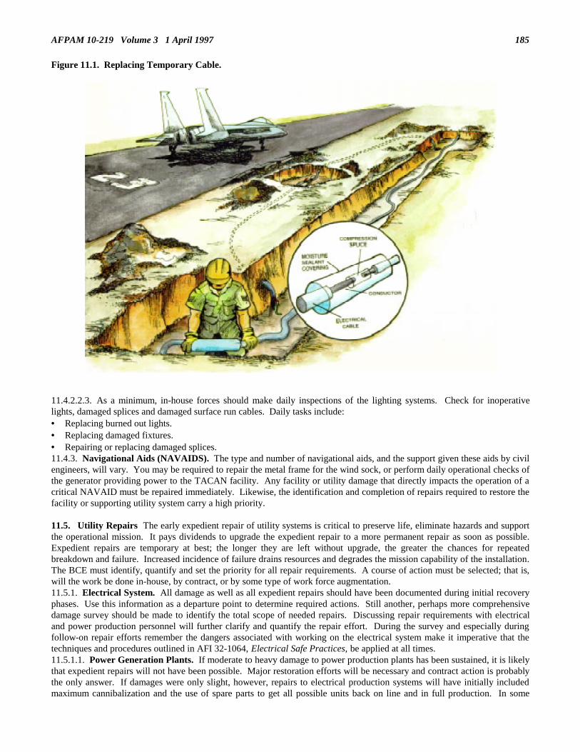
AFPAM 10-219 Volume 3 1 April 1997 185
Figure 11.1. Replacing Temporary Cable.
11.4.2.2.3. As a minimum, in-house forces should make daily inspections of the lighting systems. Check for inoperativelights, damaged splices and damaged surface run cables. Daily tasks include:• Replacing burned out lights.• Replacing damaged fixtures.• Repairing or replacing damaged splices.11.4.3. Navigational Aids (NAVAIDS). The type and number of navigational aids, and the support given these aids by civilengineers, will vary. You may be required to repair the metal frame for the wind sock, or perform daily operational checks ofthe generator providing power to the TACAN facility. Any facility or utility damage that directly impacts the operation of acritical NAVAID must be repaired immediately. Likewise, the identification and completion of repairs required to restore thefacility or supporting utility system carry a high priority.
11.5. Utility Repairs The early expedient repair of utility systems is critical to preserve life, eliminate hazards and supportthe operational mission. It pays dividends to upgrade the expedient repair to a more permanent repair as soon as possible.Expedient repairs are temporary at best; the longer they are left without upgrade, the greater the chances for repeatedbreakdown and failure. Increased incidence of failure drains resources and degrades the mission capability of the installation.The BCE must identify, quantify and set the priority for all repair requirements. A course of action must be selected; that is,will the work be done in-house, by contract, or by some type of work force augmentation.11.5.1. Electrical System. All damage as well as all expedient repairs should have been documented during initial recoveryphases. Use this information as a departure point to determine required actions. Still another, perhaps more comprehensivedamage survey should be made to identify the total scope of needed repairs. Discussing repair requirements with electricaland power production personnel will further clarify and quantify the repair effort. During the survey and especially duringfollow-on repair efforts remember the dangers associated with working on the electrical system make it imperative that thetechniques and procedures outlined in AFI 32-1064, Electrical Safe Practices, be applied at all times.11.5.1.1. Power Generation Plants. If moderate to heavy damage to power production plants has been sustained, it is likelythat expedient repairs will not have been possible. Major restoration efforts will be necessary and contract action is probablythe only answer. If damages were only slight, however, repairs to electrical production systems will have initially includedmaximum cannibalization and the use of spare parts to get all possible units back on line and in full production. In some

AFPAM 10-219 Volume 3 1 April 1997186
cases wrecking and shoring actions may have been taken to make the facility housing the power production units structurallysafe. Unreparable automatic control and monitoring systems may have been bypassed and replaced with whatever wasavailable for a "makeshift" manual operation. Now is the time to determine to what extent upgrade repairs can be made andwhat maintenance operations are required.11.5.1.1.1. Where makeshift manual controls are in use, ensure that all equipment is operating within the correct tolerancesand that the appropriate output is being achieved. Otherwise, further damage to production equipment can occur or, in thecase of incorrect output, the result can be damaged distribution equipment or worse. Ensure that replacement control panelsare requisitioned.11.5.1.1.2. Check and monitor fuel lines supplying the generators for serious leakage. Arrange for permanent repairs to bemade thereby eliminating any potential fire or safety hazards.11.5.1.1.3. Make any facility repairs that are needed to permanently weatherproof the power units and switchgear.11.5.1.2. Individual/Mobile Power Units. In most situations individual or mobile generators were expediently repairedeither through cannibalization/spare part use or by total replacement if damaged beyond immediate repair. Repair upgradeactions should be relatively minimal with the exception perhaps of repair of splinter protection features. Of more importanceis the operation and maintenance of these units and a dedicated effort will be necessary. These generators must be checked atleast daily and refueled as required. Fuel consumption data and the size of the tank should give an indication of how often aunit must be refueled. A refueling and services/inspection schedule should be developed and rigidly adhered to.11.5.1.3. Distribution System. Depending upon the nature of the disaster, repairs to the distribution systems may vary fromthe simple to the very complex. If manpower and needed materials are available, most bases have the technical capability tomake permanent repairs to the overhead distribution system. Some repairs, such as straightening leaning poles and adjustingline sag, will require no materials at all. However, the electrical distribution system at most bases is at least partiallyunderground and survey of such a system is a more difficult task. The underground system supports critical operations and isusually located in operational flying areas around the flight line. All manholes should be checked for structural damage aswell as damage to the distribution system. Extreme caution must be exercised when entering or working on undergroundsystems. Manholes can become settling points for combustible and/or extremely noxious gases. Most bases have thecapability to check for potential line insulation breakdown. This should be done so that lines can be replaced before a failureoccurs that could be detrimental to the base mission.11.5.1.3.1. If damage to the distribution system is heavy, it is likely that the distribution system off base has also sustaineddamage. In this situation, the local power company cannot be relied upon for assistance. This is the point where predisasterplanning efforts start to pay dividends. If there are electrical contractors in the local area that are capable of delivering theassistance needed, they were identified in the base’s Contingency Response Plan. The value of negotiating a requirements(on-call) contract during the contingency planning phase becomes evident now in the form of a critical time savings.11.5.1.3.2. Typical electrical distribution system upgrade and repair actions to be taken during the operations andmaintenance phase of base recovery include:• Replacement of temporary ground level distribution lines with permanent lines either above ground level or below ground
as appropriate.• Installation of new service drops to repaired facilities.• Replacement of damaged power poles.• Repair of structural damage to vaults, switching stations and security fencing.• Repair of damaged transformer banks.11.5.2. Water System. The water system is extremely important. It is needed not only for consumption, but also forfirefighting, food preparation and hygiene, decontamination, and a great many other uses. System components are normallycategorized as source, treatment, storage, and distribution.11.5.2.1. Source. If the source has remained intact or has been repaired, determine whether it is still adequate to meetcurrent needs. This determination will be based upon quantity and usability. The quantity can be calculated based on numberof personnel, firefighting requirements, and any other special considerations resulting from the contingency and recoveryeffort. Usability means potability. For firefighting and many other uses this is not so critical. The source should be treatedperiodically to ensure that it is free of contaminants. If the source is not adequate and supplementary wells have beendeveloped, they must be inspected daily to ensure a sufficient water level for the base can be maintained. Pumps also must bechecked and serviced to ensure proper running conditions.11.5.2.2. Treatment.11.5.2.2.1. If treatment facilities were only lightly damaged by the attack or disaster and expedient repairs subsequentlymade, initial efforts should be concentrated on bringing the plants back up to predisaster standards. Typical O&M phasetaskings would include:• Replacement of automatic controls and monitoring systems that were initially damaged and bypassed.• Repair of structural components to ensure weather protection and security.• Repair of any piping that was bypassed in an attempt to keep at least a portion of a plant operating.• Replacement of any auxiliary or backup pumps and motors that were damaged.

AFPAM 10-219 Volume 3 1 April 1997 187
11.5.2.2.2. If, on the other hand, treatment facilities were heavily damaged, chances are repairs will be of the magnitude thata contract or construction battalion effort would be required. Water treatment in such a situation would have to be providedthrough the use of several mobile water purification units. Such units require considerably more operating attention that anormal water treatment plant; therefore, an engineer squadron having to contend with this type of operation will have toexpect an additional demand on available manpower.11.5.2.3. Storage. Loss of storage capacity will place an additional demand on production of water. This would be aparticularly severe problem if the base developed a critical shortage in firefighting requirements. If an installation has lost asizable portion of its water storage capacity, one of the initial tasks once aircraft launch and recovery has been establishedmust be to locate and develop an alternate source of non-potable water for firefighting resupply.11.5.2.3.1. Heavily damaged water storage tanks, reservoirs, etc., will most likely be beyond repair, or at least beyond the in-house repair capability of the typical base civil engineer unit. Restoration of such facilities will have to be a contract effort.As an interim measure consider the use of flexible storage bladders positioned at critical locations around the installation.Tank trucks are another alternative.11.5.2.3.2. Minor damage to water storage structures can usually be repaired by draining the tanks and patching anypunctures that have been sustained and replacing the necessary components of any measuring gages that may have beendamaged. Ground level and above ground level tanks should be checked daily to verify structural soundness. Damagingaffects from blast pressures and ground shock may not show up immediately.11.5.2.4. Distribution System. In all probability the bulk of civil engineer water system repair taskings after an attack ordisaster will be associated with the distribution system. This is due to the wide spread nature of the piping network and itssubsequent vulnerability to collateral damage. During the O&M phase of the base recovery effort the amount of damagereceived on the distribution system will dictate the repair methodology. If heavy damages are incurred, contract and/orconstruction battalion support will definitely be required. In fact, even if damages initially appear light, some outside supportwill probably be necessary since water distribution systems are extremely fragile and problems tend to continually surfacelong after the threat of attack or natural disaster has passed. On the other hand, the importance of the water distributionsystem for maintaining and sustaining overall air base operations will mean that some in-house repair efforts will always beneeded. Typical repair tasks that can be expected for in-house accomplishment include:• Replacement of expedient above ground lines with permanent below ground piping (figure 11.2).• Replacement of damaged or bypassed valves.• Reconnection of lines that were capped.• Replacement of pipe sections that were cracked or fractured.• Replacement of damaged pumps in pumping stations.
Figure 11.2. Replacing Damaged Water Main.

AFPAM 10-219 Volume 3 1 April 1997188
11.5.2.5. Safety and Hygiene. As permanent repairs and upgrades are being accomplished, engineer personnel must beconscious of standard safety and health practices. Ground conditions are less stable after an attack or natural disaster due tosuch physical effects as shock propagation and soil saturation. It is likely that shoring for deeper excavations will benecessary and many more barricades and similar marking devices will be required due to the greater than average numbers ofline breaks incurred. Special attention must be paid to water quality. Many underground distribution system problems willinitially remain hidden and the potential for external contamination of water supplies through these undiscovered line breaksis great. For this reason, the importance of disinfecting water systems before returning them to service cannot be overemphasized. Furthermore, once the distribution system is generally operational, water quality checks should be taken atvarious points on the installation on a scheduled basis to ensure purity standards are maintained.11.5.3. Sewage System. It will be during the O&M phase of the base recovery operation that the majority of repairs to thesewage treatment and distribution system will be accomplished. As with the other utility systems, surveys should be made toidentify what expedient repairs were made following the disaster and what permanent upgrade and replacement actions shouldbe undertaken. While repairs to the sewage system are on-going, care must be taken to ensure that expedient repairs or otherworkarounds are kept serviceable. Pumps and flexible lines being used as lift station or blocked main bypasses must befrequently checked and serviced as needed. If porta-potties, chemical toilets, or other self-contained sanitary facilities areused, provisions must be made to collect, transport and properly dispose of the human wastes.11.5.3.1. Treatment Plants. Sewage treatment plants do not lend themselves very well to expedient repair. Such repairswould be generally limited to minor piping repairs, control system bypassing, and patching of berms around ponds andlagoons. If a treatment plant was damaged sufficiently enough to take it completely out of service, it is probable that acontract effort would be required for restoration purposes. Although a vulnerable facility, it is unlikely such a facility wouldbe a primary target and its normally remote location decreases its chances of receiving collateral damage.11.5.3.2. Distribution Systems. O&M efforts with regard to distribution systems usually involve repairs to distributionmains and valves, manholes, and lift stations.11.5.3.2.1. Repairs to sewer mains are needed when they are fractured, collapsed or blocked. Stoppages are normallyobvious and may be corrected by routine maintenance procedures. Hidden fractures can go unnoticed for some time.Fractures or stoppages caused by collapsed mains will require excavation so the damaged main section can be replaced(figure 11.3). Valve repairs are normally accomplished by replacing the entire valve assembly.
Figure 11.3. Replacing Temporary Sewer Lines.
11.5.3.2.2. Besides pipe collapse, stoppages to sewer lines can also be caused by structural damage to manholes. Repair ofmanhole damage can vary from merely clearing debris from the hole to replacing the entire structure. Replacing the manholemay be beyond the capability of in-house forces; therefore, be prepared to ask for contract or construction battalion support.On the other hand, clearing debris is relatively easy, requiring a minimal demand on resources. Once debris has been cleared,remember to mark off or barricade the manhole area as a safety precaution.
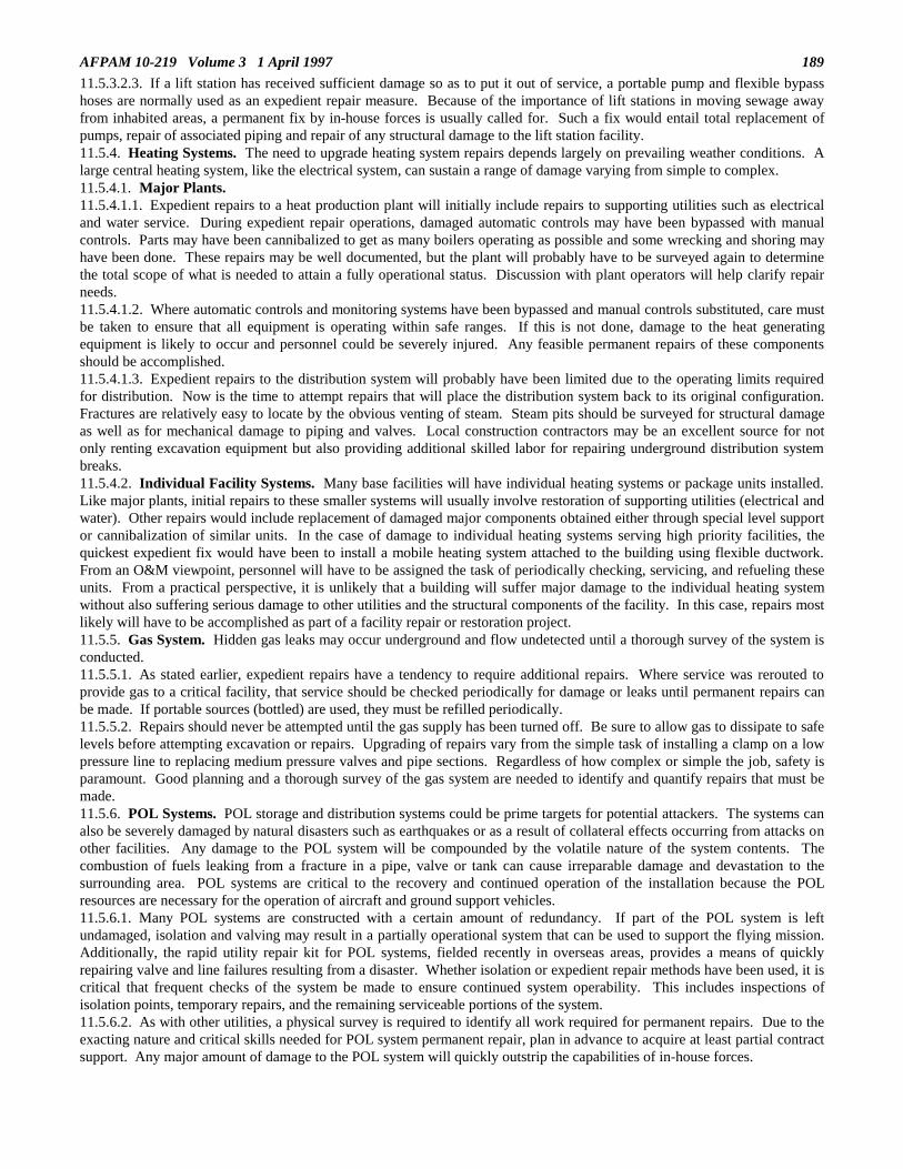
AFPAM 10-219 Volume 3 1 April 1997 189
11.5.3.2.3. If a lift station has received sufficient damage so as to put it out of service, a portable pump and flexible bypasshoses are normally used as an expedient repair measure. Because of the importance of lift stations in moving sewage awayfrom inhabited areas, a permanent fix by in-house forces is usually called for. Such a fix would entail total replacement ofpumps, repair of associated piping and repair of any structural damage to the lift station facility.11.5.4. Heating Systems. The need to upgrade heating system repairs depends largely on prevailing weather conditions. Alarge central heating system, like the electrical system, can sustain a range of damage varying from simple to complex.11.5.4.1. Major Plants.11.5.4.1.1. Expedient repairs to a heat production plant will initially include repairs to supporting utilities such as electricaland water service. During expedient repair operations, damaged automatic controls may have been bypassed with manualcontrols. Parts may have been cannibalized to get as many boilers operating as possible and some wrecking and shoring mayhave been done. These repairs may be well documented, but the plant will probably have to be surveyed again to determinethe total scope of what is needed to attain a fully operational status. Discussion with plant operators will help clarify repairneeds.11.5.4.1.2. Where automatic controls and monitoring systems have been bypassed and manual controls substituted, care mustbe taken to ensure that all equipment is operating within safe ranges. If this is not done, damage to the heat generatingequipment is likely to occur and personnel could be severely injured. Any feasible permanent repairs of these componentsshould be accomplished.11.5.4.1.3. Expedient repairs to the distribution system will probably have been limited due to the operating limits requiredfor distribution. Now is the time to attempt repairs that will place the distribution system back to its original configuration.Fractures are relatively easy to locate by the obvious venting of steam. Steam pits should be surveyed for structural damageas well as for mechanical damage to piping and valves. Local construction contractors may be an excellent source for notonly renting excavation equipment but also providing additional skilled labor for repairing underground distribution systembreaks.11.5.4.2. Individual Facility Systems. Many base facilities will have individual heating systems or package units installed.Like major plants, initial repairs to these smaller systems will usually involve restoration of supporting utilities (electrical andwater). Other repairs would include replacement of damaged major components obtained either through special level supportor cannibalization of similar units. In the case of damage to individual heating systems serving high priority facilities, thequickest expedient fix would have been to install a mobile heating system attached to the building using flexible ductwork.From an O&M viewpoint, personnel will have to be assigned the task of periodically checking, servicing, and refueling theseunits. From a practical perspective, it is unlikely that a building will suffer major damage to the individual heating systemwithout also suffering serious damage to other utilities and the structural components of the facility. In this case, repairs mostlikely will have to be accomplished as part of a facility repair or restoration project.11.5.5. Gas System. Hidden gas leaks may occur underground and flow undetected until a thorough survey of the system isconducted.11.5.5.1. As stated earlier, expedient repairs have a tendency to require additional repairs. Where service was rerouted toprovide gas to a critical facility, that service should be checked periodically for damage or leaks until permanent repairs canbe made. If portable sources (bottled) are used, they must be refilled periodically.11.5.5.2. Repairs should never be attempted until the gas supply has been turned off. Be sure to allow gas to dissipate to safelevels before attempting excavation or repairs. Upgrading of repairs vary from the simple task of installing a clamp on a lowpressure line to replacing medium pressure valves and pipe sections. Regardless of how complex or simple the job, safety isparamount. Good planning and a thorough survey of the gas system are needed to identify and quantify repairs that must bemade.11.5.6. POL Systems. POL storage and distribution systems could be prime targets for potential attackers. The systems canalso be severely damaged by natural disasters such as earthquakes or as a result of collateral effects occurring from attacks onother facilities. Any damage to the POL system will be compounded by the volatile nature of the system contents. Thecombustion of fuels leaking from a fracture in a pipe, valve or tank can cause irreparable damage and devastation to thesurrounding area. POL systems are critical to the recovery and continued operation of the installation because the POLresources are necessary for the operation of aircraft and ground support vehicles.11.5.6.1. Many POL systems are constructed with a certain amount of redundancy. If part of the POL system is leftundamaged, isolation and valving may result in a partially operational system that can be used to support the flying mission.Additionally, the rapid utility repair kit for POL systems, fielded recently in overseas areas, provides a means of quicklyrepairing valve and line failures resulting from a disaster. Whether isolation or expedient repair methods have been used, it iscritical that frequent checks of the system be made to ensure continued system operability. This includes inspections ofisolation points, temporary repairs, and the remaining serviceable portions of the system.11.5.6.2. As with other utilities, a physical survey is required to identify all work required for permanent repairs. Due to theexacting nature and critical skills needed for POL system permanent repair, plan in advance to acquire at least partial contractsupport. Any major amount of damage to the POL system will quickly outstrip the capabilities of in-house forces.

AFPAM 10-219 Volume 3 1 April 1997190
11.6. Facilities and Services Upgrading of expedient repairs to critical facilities and expanding the level of requiredservices are salient features of the BCE’s O&M effort after an attack or natural disaster has occurred. Because of thepotentially large scope of these efforts, particularly with respect to facilities, count on using contract and constructionbattalion support for at least a portion of this requirement.11.6.1. Facilities. Recovery actions on facilities are done in accordance with the priority of the facility. Efforts are directedtowards upgrading expedient repairs and demolishing buildings presenting a danger to personnel.11.6.1.1. The BCE’s efforts regarding facility repair must begin with a thorough inspection of facilities so that the scope anddepth of needed repairs can be determined. Use the Installation Facility Priority List as a guide to the inspection order and,once this list is exhausted, check those other facilities that are known to have sustained damage. Minor permanent repairactions should be identified for in-house accomplishment. Facility restoration beyond in-house capabilities must also beidentified and forwarded to the major command for allocation to contract or troop construction efforts.11.6.1.2. Typical tasks that in-house forces should be prepared to accomplish during the postdisaster O&M phase include:• Replacement of expedient plastic sheeting and canvas patches with plywood or plexiglass patches (figure 11.4).• Upgrade of shoring for facilities that will be repaired by other than in-house forces. • Isolation of damaged electrical circuits in a facility that would permit the remainder of a facility to be restored to electrical
power.• Repair of utility service lines to critical facilities.• Restoration of structural integrity to facilities that are only slightly damaged.• Repair of security fencing/entry gates to critical resource areas.• Demolition of severely damaged facilities (salvage useable materials).• Sectioning off of damaged portions of a facility to allow use of the remainder of the facility.
Figure 11.4. Plywood Patches.
11.6.2. Garbage and Refuse Disposal. Regardless of postdisaster conditions, garbage and refuse will continue toaccumulate and methods for handling these items must be devised. Unfortunately, damage to collection equipment orincinerating equipment may temporarily impair or halt collection and disposal efforts. Garbage and refuse is usually disposedof by sanitary fills, incineration, sale or contract. In most cases a contract service is used. It is likely that such service will beinterrupted after a disaster has occurred, particularly an air base attack. During this period in-house forces will have toperform the task. Once contract support has been re-established, a joint effort may still be necessary. Although additionalcosts may be incurred, contractors should be instructed to use all available transportation for collection and disposal, andassist in removal of base-wide debris. If off base disposal sites are out of service or inaccessible, on base locations must beidentified. At these sites garbage, refuse and debris can either be buried, burned, or a combination of both. In areas of higherpopulation density, such as base housing, occupants can burn or bury their own refuse until adequate disposal facilities aremade available. Common burial pits can be established for this purpose. Plan on closely monitoring this type of "self-help"operation--uncontrolled refuse disposal can lead to serious fire and sanitation hazards. If on base locations are created forgarbage and refuse disposal, ensure that a stringent pest control program is instituted to alleviate the danger of disease spread.11.6.3. Snow Removal and Ice Control. Removing snow and ice from airfield pavements is as important as repairingdamaged airfield pavements. In the postdisaster environment, however, more care must be taken in some areas. For example,standard snow removal techniques may not work on repaired runway areas. It is likely that plow blades will catch the edgesof anchored fiberglass mats and perhaps other temporary repairs, thereby damaging the repair and probably the plow as well.A lot of hand work and a carefully operated front-end loader may be necessary to clear crater repair areas. Additionally, snow

AFPAM 10-219 Volume 3 1 April 1997 191
removal equipment operators will have to be observant of the mobile arresting barrier location since it will likely bepositioned differently than the permanently installed barriers. If the runway has not been totally opened and a minimumoperating strip is still in use, the situation is even more complicated. Equipment operators will also have to avoid thetemporary airfield lighting and edge markers around the operating strip.11.6.3.1. At the onset of heavy snow conditions and the ceasing of flying operations, it may be advisable to further mark theboundaries of the operating strip with flags or cones so that its outline is discernible once snow removal operations begin. Ifthis is not feasible due to weather conditions, it may be necessary to identify the edges of the operating strip immediately priorto rolling the snow removal equipment to the airfield. It would also be advisable to mark the boundaries of any repaired areassince even a little snowfall will mask their locations.11.6.3.2. At most locations snow and ice removal will occur simultaneously on the airfield and base thoroughfares. Thefollowing is a general list of the more important areas requiring snow and ice removal in a postattack environment:• Runway, primary taxiways, and alert parking areas.• Aircraft parking areas and shelter entrances.• Accessways to aircraft maintenance hangars.• Access roads to munitions storage areas.• Fire routes to mission critical facilities.• Access routes to POL dispensing points.• Primary base thoroughfares.
11.7. Alternate Transportation Routes. Refueling and rearming of aircraft, evacuation of personnel, and other emergencyresponses require usable travel routes. The BCE is responsible for maintenance and repair of all traffic routes includingmaking alternate routes available. Alternate routes are needed when the primary route has been interdicted or travel on theprimary route would be hazardous (e.g., down wind of a toxic substance source).11.7.1. Alternate Route Development. Air Force bases are normally constructed with an adequate network of roadsaffording ample opportunity for development of alternate routes. If all possible access routes have been damaged, the firstoption is to go around the damage by removing surface obstacles such as curbing, directing traffic onto the unpaved areaaround the damaged portion of the street, and then back onto the street once the damage has been cleared. If possible, try totie parking lots into the diversion route since this will provide at least a partially paved surface. Also be aware of overheadclearances. Building overhangs, electric and telephone lines, and tree limbs can quickly hinder traffic flow. Check thatutilities, especially water, gas, and sewer, are not running close to the surface in the diversion route area. If they are, chooseanother location for the route or ensure that a hard surface such as AM-2 matting is placed over the lines to better distributevehicle weights. When supplies are readily available, cover the diversion route with crushed rock or similar material toproduce a better, weather resistant travel surface (figure 11.5).
Figure 11.5. Alternate Route Under Construction.

AFPAM 10-219 Volume 3 1 April 1997192
11.7.2. Transportation Route Repair. If going around the damage is not possible, the only other option is to repair thedamage. This can be done expediently in a manner similar to rapid runway repair. Expedient road repair consists ofremoving debris, backfilling the crater and compacting the fill. Difficult repairs, like shoring up a bridge superstructure orapplying a surface coarse should be avoided. Rely on contractors or other troop construction units to accomplish this type ofwork. Permanent road repairs should not be attempted until the crisis is past and permanent recovery actions are wellunderway.
11.8. Resupply and Stockpiling. By now much, if not all, of your stockpiled materials have been used up, damaged, ordestroyed. To upgrade repairs and continue operation, steps must be taken for resupply and possible stockpiling of essentialmaterials.11.8.1. Any preplanning efforts that have been taken pay off now, in that it is not necessary to "build from scratch" a listingof needed materials. Many have already been identified during the preplanning process. This compilation, coupled withbench stock lists, shop stocks, special levels, war reserve material, and material identified as a result of damage assessmentsurveys will produce a pretty large shopping list.11.8.2. Once a materials requirements listing is assembled, the acquisition process is begun, normally through base supplyand the base contracting office. Contingency and wartime resupply usually comes from two sources--the CONUS and thelocal economy. The CONUS effort oftentimes is initiated via a "push" system where materials are shipped prior to actualordering by units in the field. The items shipped are common materials that traditionally have been needed for engineersupport during wartime. In this way the materials identification and ordering time delay is eliminated at least for the initialresupply action. Follow-on stocks based on requisitions from the field flow later. For planning purposes assume a 60-daytransit time for both initial resupply and these follow-on stocks. This essentially means you will have to rely on whatever youhave on hand and the local economy to support your efforts for at least the 60-day period following the start of hostilities.11.8.3. Exploit the local economy as much as possible as a source of supply. One of your initial tasks upon arrival at yourbeddown location should be to identify local contractors and material vendors. Visit their locations and see what is availableboth in terms of scope of items carried and quantities normally in stock. Provide this source information to base supply andcontracting when you place orders. If worst comes to worse also arrange for transportation of materials if this is posing aproblem.11.8.4. As materials are received every effort must be made to control and track use of the materials. This will beparticularly difficult in the chaotic recovery environment. As materials are used and stocks dwindle, material control musttake action to replenish stocks on a regular basis. The goal should be to develop a supply flow that meets recovery needs andavoids excessive delays while at the same time does not flood the base with more materials than will ever be required.Particular care must be taken to order only what is needed and not grossly inflate requirements. On the other hand, ensurethat emergency stocks such as special levels that have been depleted are also replenished. Even though such stocks may notbe immediately needed, it is only prudent to rebuild on-hand material quantities to predisaster levels. Do not forget toincorporate "lessons learned" into your stockage requirements. If you find that additional critical items are necessary tosupport postdisaster conditions, add them to your emergency stockage lists.11.8.5. Because the quantity of resupply material may be greater than available warehouse space, it could become necessaryto stockpile material elsewhere. Remote stockpiling of resources (figure 11.6) at or near a proposed job site can increaseefficiency through reduction of waste and material handling time. Additionally, such stockpiling serves as a dispersalmeasure thereby affording some added protection from the effects of potential future attacks. Open and dispersed storage ofmaterials has drawbacks, however, which must be countered. Adequate security for these resources is a primary considerationto prevent weather damage, pilfering, or vandalism. This will present the need to inspect and segregate materials as theyarrive. Items that are weather sensitive must be stored under cover. Materials that have high value such as copper wireshould likewise be secured under cover. Items that are good "trading stock" such as plywood and lumber should be at leastfenced-in with concertina wire.

AFPAM 10-219 Volume 3 1 April 1997 193
Figure 11.6. Stockpiling of Resources.
11.9. Summary. It is important to make a smooth transition from the expedient repair mode to a more sustained mode ofoperations and maintenance accompanied by permanent repair upgrades. Although the conditions of the emergency may havesubsided somewhat, the installation is still in a recovery mode and emergency action is still the modus operandi. Carefullyconsider your options concerning specific repairs and the operations and maintenance requirements for various air base utilitysystems and facilities. Develop a restoration plan that includes total requirements, considers priorities, and assesses avenuesavailable (work agencies) to affect repairs. Do not forget to include essential services such as refuse disposal and snow andice control and make provisions for an effective resupply program. Maintenance and repair of transportation routes will playa key role in enhancing other repair operations. Be aware that a clear differentiation is established between Army and AirForce responsibilities in regard to the post attack restoration effort. However, differentiation on paper does not meananything if those forces are not available when needed. Bottom line, be flexible and ensure effective employment of thoseresources you control.

194 AFPAM 10-219 Volume 3 1 April 1997
Chapter 12
SECURITY ACTIVITIES
"Even in friendly territory a fortified camp should be set up; a general should never haveto say: ’I did not expect it’."
Mauricius Flavius Tiberius, Roman Emperor AD 600
12.1. Introduction. In previous conflicts, the geographical location of our bases left them virtually immune to ground attack.When ground attacks did occur, as was the case in Vietnam, the enemy generally did not commit a large number of forces andthe Army provided some of its resources to protect theater air bases against such attacks. In today’s environment ofworldwide global commitments at potentially remote locations, the protection of Air Force people and assets takes on awholly different flavor. Tending to be the first armed forces on the scene at multiple locations during contingencies, the AirForce must be prepared to take a larger role in defense and protection of its base infrastructure, materiel, and personnel.Consider, for example, the impact a successful concerted, perhaps even suicidal, attack would have had on our in-theater airbases at the start of the Gulf War deployment. While probably not affecting the outcome of the conflict, we could have lost aconsiderable quantity of high priority assets and aircraft, taken many casualties, and adversely influenced the superb supportreceived from the American populace. Given the overwhelming success experienced by Allied Air Forces during the DesertStorm conflict, such an “initial strike” scenario is not beyond the realm of possibility in future contingencies. We, asengineers, have a part to play in preventing just such an occurrence.
12.2. Overview. This chapter discusses the levels of threat activity faced by air bases during contingency operations andaddresses engineer actions relating to air base security. Initially some basic combat skills and concepts will be presented thatall engineers should be conversant with. This will be followed by information on convoy procedures and work party security.Engineer actions pertaining to air base defense will then be presented. Lastly, some thoughts on antiterrorism planning willbe outlined.
12.3. Threats to US Air Force Bases. Current and accurate threat information is vital for planning, preparing, andresponding to security related operations. Threats to air bases are grouped into three levels, each denoting a responsibility foraction. An enemy may use one or all of these to attack air bases. Base defense forces must be capable of reacting to nuclear,biological, and chemical (NBC) warfare during all threat levels.12.3.1. A Level I threat includes small-scale activities conducted by agents, sympathizers, and partisans, and agent-supervised or independently initiated terrorist activities. Level I threats must be defeated by base self-defense forces.12.3.2. Level II includes long-range reconnaissance, intelligence gathering, and sabotage operations conducted by specialpurpose forces, guerrilla forces, unconventional forces, or small tactical units. Level II threats must be defeated or delayeduntil assistance comes from response forces, usually US Army military police units.12.3.3. Level III threats include major attacks by aircraft and theater missiles armed with conventional weapons or NBCweapons, in addition to major ground attacks. Level III threats may require timely assistance from tactical combat forces;however, defense forces must be able to delay these threats.
12.4. Security Planning For planning purposes engineer forces should be considered to play a limited defensive role and tohave no offensive capability with respect to air base security. Nevertheless, even in these restrained postures, engineers mustbe capable of performing their primary beddown, operations, and recovery missions in a hostile environment. There is noguarantee that sufficient security police, US Army, or host nation forces will be available whenever required to supportengineer requirements. Furthermore, for the air base defense mission, all air base personnel are held responsible and engineerforces are specifically identified in Air Force directives to take an active part in this tasking. These security related tasksmake it imperative that engineer forces have a basic knowledge of self-protection techniques and defensive operationsassociated with four major areas—personal security, convoying, work party security, and air base defense.12.4.1. Personal Security. Personal security involves an understanding of several basic concepts and procedures whichwork together providing an individual with a better chance of survival in a hostile situation while, at the same time, ensuringtask accomplishment and air base survival.12.4.1.1. Cover, Concealment, and Camouflage. If the enemy can see you, he can hit you with his fire. So you must beconcealed from enemy observation and have cover from enemy fire. When the terrain does not provide natural cover andconcealment, you must prepare your cover and use natural and man-made materials to camouflage yourself, your equipment,and your position.

AFPAM 10-219 Volume 3 1 April 1997 195
12.4.1.1.1. Cover. Cover gives protection from bullets, fragments, and some NBC agents. Cover, which can be natural orman-made, can also conceal you from enemy observation. Natural cover includes things as logs, trees, stumps, ravines, andhollows. Man-made cover includes such things as fighting positions, trenches, walls, rubble, and craters. When in adefensive posture, a fighting position using natural cover from the surrounding terrain is normally constructed. To getprotection from enemy fire when moving, use routes that put cover between you and the places where the enemy is known orthought to be. Use ravines, gullies, hills, wooded areas, and walls to keep the enemy from seeing and firing at you. Avoidopen areas, and do not skyline yourself on hilltops and ridges.12.4.1.1.2. Concealment. Concealment is anything that hides you from enemy observation. It does not protect you fromenemy fire, however. Like cover, concealment can be natural or man-made. Natural concealment includes items such asbushes, trees, grass, and shadows. Manmade concealment (figure 12.1) includes battle dress uniforms, camouflage nets, facepaint, and natural material that has been moved from its original location. To be effective, however, man-made concealmentmust blend into the natural concealment offered by the terrain. Contributing to concealment are three other factors that shouldbe considered—light discipline, noise discipline, and movement discipline.
Figure 12.1. Man-Made Concealment—Camouflage Nets and BDUs.
12.4.1.1.2.1. Light discipline is controlling the use of lights at night by such things as not smoking in the open, not walkingaround with a flashlight on, and not using vehicle headlights.12.4.1.1.2.2. Noise discipline is taking action to deflect sounds generated by your unit (such as operating equipment) awayfrom the enemy and, when possible, using methods to communicate that do not generate sounds (arm and hand signals).12.4.1.1.2.3. Movement discipline includes such things as not moving about fighting positions unless necessary, and notmoving on routes that lack cover and concealment. Movement draws attention. When you give arm and hand signals or walkabout your position, your movement can be seen by the naked eye at long ranges. When in a defensive posture, stay low andmove only when necessary. If movement is a must, do so only on covered and concealed routes. A note of caution--darknessalone cannot hide you from enemy observation. Night vision devices let them find you in darkness.12.4.1.1.3. Camouflage. Camouflage is anything you use to keep yourself, your equipment, and your position from lookinglike what they are. Both natural and man-made material can be used for camouflage. When natural material is used, overtime it will often die, fade, or otherwise lose its effectiveness and should be changed frequently. Likewise, man-madematerial may wear off or also fade. When this happens, you and your equipment or position may no longer blend with thesurroundings--making it easy for the enemy to spot. Some camouflage considerations include:12.4.1.1.3.1. Shine. Shine may also attract the enemy’s attention. In darkness, it may be a light such as a burning cigaretteor flashlight. In daylight, it can be the reflection from a polished surface such as shiny mess gear, a worn helmet, awindshield, a watch crystal or even exposed skin. To reduce shine, cover your skin with clothing and face paint. Also dullthe surfaces of equipment and vehicles with paint, mud, or camouflage material (figure 12.2).

AFPAM 10-219 Volume 3 1 April 1997196
Figure 12.2. Shine Reduction By Vehicle Painting.
12.4.1.1.3.2. Shape. Shape is outline or form. The shape of a helmet and human body are easily distinguishable. Usecamouflage and concealment to break up shapes and blend them with their surroundings. But, be careful not to overdo it.12.4.1.1.3.3. Colors. Colors can also be a “dead give-away.” The colors of your skin, uniform, and equipment may help theenemy detect you if they contrast with the background. For example, a green uniform will contrast with snow-covered terrain.Camouflage yourself and your equipment to blend with the surroundings.12.4.1.1.3.4. Dispersion. Dispersion is the spreading of personnel, vehicles, and equipment over a wide area. It is usuallyeasier for the enemy to detect individuals when they are bunched. So, spread out. The distance between you and anotherperson will vary with the terrain, degree of visibility, and enemy situation.12.4.1.2. Movement Techniques. In the event of a confrontation with an opposing force, individuals will normally berequired to move to obtain cover. Use the following techniques and precautions for movement prior to and during anencounter with an enemy force:12.4.1.2.1. Camouflage yourself and your equipment.12.4.1.2.2. Wear soft, well-fitting clothes.12.4.1.2.3. Tape your dog tags together and to the chain so they cannot slide or rattle. Tape or pad the parts of your weaponand equipment that rattle or are so loose that they may snag (the tape or padding must not interfere with the operation of theweapon or equipment). When taping is completed test for noise by shaking.12.4.1.2.4. Do not carry unnecessary equipment. Move from cover position to cover position (taking no longer than 3 to 5seconds between positions).12.4.1.2.5. Stop, look, and listen before moving. Look for the next position before leaving a position.12.4.1.2.6. Look for covered and concealed routes on which to move.12.4.1.2.7. Change directions slightly from time to time when moving through tall grass.12.4.1.2.8. Cross roads and trails at places that have the most cover and concealment (large culverts, low spots, curves, orbridges).12.4.1.2.9. Avoid steep slopes and places with loose dirt or stones.12.4.1.2.10. Avoid cleared, open areas and tops of hills and ridges.12.4.1.2.11. If you alarm birds or animals, remain in position and observe briefly.12.4.1.2.12. Take advantage of distractions provided by noise.12.4.1.3. Methods of Movement. In addition to walking, you may move in one of four other methods—low crawl, highcrawl, rush, and spider crawl. Bear in mind these movement methods are meant to be used to keep you out of enemy contact,allow you to reach a covered, concealed position, or withdraw from an area safely. There is no intent to have engineerpersonnel move toward an enemy force for the purpose of offensive maneuvers or actions.

AFPAM 10-219 Volume 3 1 April 1997 197
12.4.1.3.1. Low Crawl. The low crawl (figure 12.3) gives you the lowest silhouette. Use it to cross places where theconcealment is very low and enemy fire or observation prevents you from getting up. Keep your body flat against the ground.With your firing hand, grasp your weapon sling at the upper sling swivel. Let the front handguard rest on your forearm(keeping the muzzle off of the ground), and let the weapon butt drag on the ground. To move, push your arms forward andpull your firing side leg forward. Then pull with your arms and push with your leg. Continue this action throughout themove.
Figure 12.3. Low Crawl.
12.4.1.3.2. High Crawl. The high crawl (figure 12.4) lets you move faster than the low crawl and still gives you a lowsilhouette. Use this crawl when there is good concealment but enemy fire prevents you from moving in an upright posture.Keep your body off of the ground and resting on your forearms and lower legs. Cradle your weapon in your arms and keep itsmuzzle off the ground. Keep your knees well behind your buttocks so your body will stay low. To move, alternately advanceyour right elbow and left knee, then your left elbow and right knee.
Figure 12.4. High Crawl.
12.4.1.3.3. Rush. The rush (figure 12.5) is the fastest way to move from one position to another. Each rush should last from3 to 5 seconds. Rushes are kept short to keep enemy machine gunners or riflemen from tracking you. However, do not stopand hit the ground in the open just because 5 seconds have passed. Always try to hit the ground behind some cover. Beforemoving, pick out your next cover and concealed position and the best route to it. Make your move from the prone position asfollows:

AFPAM 10-219 Volume 3 1 April 1997198
Figure 12.5. Rush Movement.
12.4.1.3.3.1. Slowly raise your head and pick your next position and the route to it.12.4.1.3.3.2. Slowly lower your head.12.4.1.3.3.3. Draw your arms into your body (keeping your elbows in).12.4.1.3.3.4. Pull your right leg forward.12.4.1.3.3.5. Raise your body by straightening your arms.12.4.1.3.3.6. Get up quickly.12.4.1.3.3.7. Run to the next position.12.4.1.3.3.8. When you are ready to stop moving, plant both of your feet.12.4.1.3.3.9. Drop to your knees (at the same time slide a hand to the butt of your weapon).12.4.1.3.3.10. Fall forward, breaking the fall with the butt of the weapon.12.4.1.3.3.11. Go to a prone firing position.12.4.1.3.4. Spider Crawl. At times it may become necessary to descend to the ground quickly from an elevated position orto move over an obstacle. To jump to the ground may cause injury due to an unfamiliarity with the terrain or height of theobstacle. The “spider crawl” (figure 12. 6) is used in these circumstances to avoid injury and to reduce the silhouette whilegoing over an object. The “spider crawl” is performed as follows:

AFPAM 10-219 Volume 3 1 April 1997 199
Figure 12.6. “Spider Crawl” Movement.
12.4.1.3.4.1. As you move along the obstacle or structure, you must maintain a low profile to reduce the silhouette. Placeyour weapon in your lead hand.12.4.1.3.4.2. Your leading hand and foot are extended over the edge of the obstacle in a “spread eagle” position while yourtrailing hand and foot are pressed firmly against the top of the obstacle.12.4.1.3.4.3. Your lead hand and foot are slowly extended down the vertical face of the obstacle until only your trail handand foot are on the top.12.4.1.3.4.5. Your trail foot is released, closely followed by your trail hand using your lead hand as a pivot to control thedrop.12.4.1.3.4.6. You should land on the balls of your feet, with your legs spread approximately shoulder width. Your kneesshould be flexed and your body should be in a slightly crouched position hugging the obstacle.12.4.1.3.4.7. The “spider crawl” should be practiced for both right-handed, as well as left-handed descent. The placement ofyour lead hand will determine which direction you will be facing once you hit the ground.12.4.1.4. Small Group Movement. For those occasions when engineer personnel may have to move into an unsecure orpotentially hostile area remote from the main base or at an off-base location, small group movement techniques may be calledfor. In such situations personnel are organized into fire team formations. Fire teams normally consist of four-man groups.Each team member is identified by number (1, 2, 3, and 4)--for our purposes all members are rifleman with the number fourman being the team leader. The wedge (figure 12.7) is the basic formation for a fire team. The interval between personnel isnormally 10 meters. The wedge expands and contracts depending on the terrain. When rough terrain, poor visibility, or otherfactors make control of the wedge difficult, fire teams modify the wedge. The sides of the wedge can contract to the pointwhere the wedge resembles a single file (figure 12.8). When moving in less rugged terrain, where control is easier, personnelexpand or resume their original positions. If two or more fire teams are to be traveling together, the wedge or file formationsare again used (figures 12.9 and 12.10). Usually an element leader is also present. A 20 meter separation between theelement leader and the second fire team is normally maintained if contact with an enemy force is not likely. If contact with anenemy force is possible, however, the formation is altered somewhat. The element leader and the second fire team fall back

AFPAM 10-219 Volume 3 1 April 1997200
to a 50 meter separation from the lead fire team (figure 12.11). This formation is called traveling overwatch. If fired uponduring movement, figures 12.12 and 12.13 illustrate the pivoting techniques used for positioning a wedge formation torespond to attacks from the flanks.
Figure 12.7. Wedge Formation.
Figure 12.8. File Formation.

AFPAM 10-219 Volume 3 1 April 1997 201
Figure 12.9. Two Fire Team Wedge Formation.

AFPAM 10-219 Volume 3 1 April 1997202
Figure 12.10. Two Fire Team File Formation.

AFPAM 10-219 Volume 3 1 April 1997 203
Figure 12.11. Two Fire Team Traveling Overwatch Formation.

AFPAM 10-219 Volume 3 1 April 1997204
Figure 12.12. Left Pivot Movement.
Figure 12.13. Right Pivot Movement.
12.4.1.5. Fighting Position Construction. When defending, personnel need cover from fire and concealment fromobservation. Cover and concealment are best provided by some type of fighting position. This may be an existing hole, a
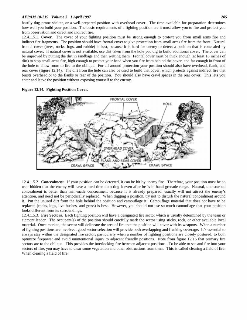
AFPAM 10-219 Volume 3 1 April 1997 205
hastily dug prone shelter, or a well-prepared position with overhead cover. The time available for preparation determineshow well you build your position. The basic requirements of a fighting position are it must allow you to fire and protect youfrom observation and direct and indirect fire.12.4.1.5.1. Cover. The cover of your fighting position must be strong enough to protect you from small arms fire andindirect fire fragments. The position should have frontal cover to give protection from small arms fire from the front. Naturalfrontal cover (trees, rocks, logs, and rubble) is best, because it is hard for enemy to detect a position that is concealed bynatural cover. If natural cover is not available, use dirt taken from the hole you dig to build additional cover. The cover canbe improved by putting the dirt in sandbags and then wetting them. Frontal cover must be thick enough (at least 18 inches ofdirt) to stop small arms fire, high enough to protect your head when you fire from behind the cover, and far enough in front ofthe hole to allow room to fire to the oblique. For all-around protection your position should also have overhead, flank, andrear cover (figure 12.14). The dirt from the hole can also be used to build that cover, which protects against indirect fire thatbursts overhead or to the flanks or rear of the position. You should also have crawl spaces in the rear cover. This lets youenter and leave the position without exposing yourself to the enemy.
Figure 12.14. Fighting Position Cover.
12.4.1.5.2. Concealment. If your position can be detected, it can be hit by enemy fire. Therefore, your position must be sowell hidden that the enemy will have a hard time detecting it even after he is in hand grenade range. Natural, undisturbedconcealment is better than man-made concealment because it is already prepared, usually will not attract the enemy’sattention, and need not be periodically replaced. When digging a position, try not to disturb the natural concealment aroundit. Put the unused dirt from the hole behind the position and camouflage it. Camouflage material that does not have to bereplaced (rocks, logs, live bushes, and grass) is best. However, you should not use so much camouflage that your positionlooks different from its surroundings.12.4.1.5.3. Fire Sectors. Each fighting position will have a designated fire sector which is usually determined by the team orelement leader. The occupant(s) of the position should carefully mark the sector using sticks, rock, or other available localmaterial. Once marked, the sector will delineate the area of fire that the position will cover with its weapons. When a numberof fighting positions are involved, good sector selection will provide both overlapping and flanking coverage. It’s essential toalways stay within the designated fire sector, particularly when a number of fighting positions are closely postured, to bothoptimize firepower and avoid unintentional injury to adjacent friendly positions. Note from figure 12.15 that primary firesectors are to the oblique. This provides the interlocking fire between adjacent positions. To be able to see and fire into yoursectors of fire, you may have to clear some vegetation and other obstructions from them. This is called clearing a field of fire.When clearing a field of fire:

AFPAM 10-219 Volume 3 1 April 1997206
Figure 12.15. Fighting Position Fire Sectors.
12.4.1.5.3.1. Do not disclose your position by careless or too much clearing.12.4.1.5.3.2. Leave a thin, natural screen of vegetation to hide your position.12.4.1.5.3.3. Cut off lower branches of large, scattered trees in sparsely wooded areas.12.4.1.5.3.4. Clear underbrush only where it blocks your view.12.4.1.5.3.5. Remove cut brush, limbs, and weeds so the enemy will not spot them.12.4.1.5.3.6. Cover cuts on trees and bushes forward of your position with mud or dirt.12.4.1.5.3.7. Leave no trails as clues for the enemy.12.4.1.5.4. Hasty Fighting Position. This type of fighting position is built when there is little or no time to prepare a moresubstantial position or when the work duration in an area is to be short. It is located behind whatever cover is available. Itshould give frontal protection from direct fire while allowing fire to the front and oblique. A hasty position may consistsimply of a backpack placed beside a tree of large rock. For protection from indirect fire, a hasty fighting position should bein a small depression or hole at least 18 inches deep. The term hasty position does not mean there is no digging. Even ifthere are only a few minutes, a prone shelter can be scraped out or dug to provide some protection (figure 12.16). Hastypositions can also be the first step in construction of more elaborate positions.
Figure 12.16. Hasty Fighting Position.
12.4.1.5.5. One-Person Fighting Position. The one-person defensive position (figure 12.17) allows flexibility in the use ofcover, since the hole needs only to be wide enough for one person (plus gear). It does not have the security of a two-personposition; therefore, it must allow an airman to apply defensive fire to the front or to the oblique from behind frontal cover.

AFPAM 10-219 Volume 3 1 April 1997 207
Figure 12.17. One-Person Fighting Position.
12.4.1.5.6. Two-Person Fighting Position. The two-person position (figure 12.18) is generally preferred over a one-personposition for several reasons. Occupancy by two people permits all-around observation and defense; the position can beeffectively manned for longer periods of time (one individual provides security for the work site while the other is digging orresting); and when manned by one person overwatching the work site, the position can also serve as a defensive cover forothers when a work party comes under fire. Finally, there is a psychological advantage when two people support each otherin a hostile situation. The basic position can be modified by extending around the sides of the frontal cover (figure 12.19) oradding overhead cover using logs and sod.
Figure 12.18. Two-Person Fighting Position.
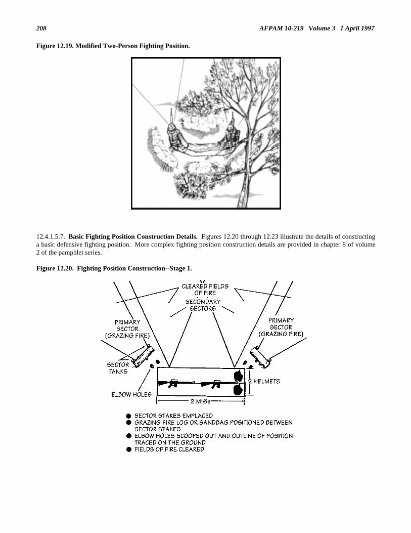
AFPAM 10-219 Volume 3 1 April 1997208
Figure 12.19. Modified Two-Person Fighting Position.
12.4.1.5.7. Basic Fighting Position Construction Details. Figures 12.20 through 12.23 illustrate the details of constructinga basic defensive fighting position. More complex fighting position construction details are provided in chapter 8 of volume2 of the pamphlet series.
Figure 12.20. Fighting Position Construction--Stage 1.

AFPAM 10-219 Volume 3 1 April 1997 209
Figure 12.21. Fighting Position Construction--Stage 2.
Figure 12.22. Fighting Position Construction--Stage 3.

AFPAM 10-219 Volume 3 1 April 1997210
Figure 12.23. Fighting Position Construction--Stage 4.
12.4.1.6. Recognition Code Systems. A system of constantly changing passwords, number codes and duress words are anessential part of the security of any military activity during periods of conflict. Code systems afford guards a quick means ofidentifying both friendly and enemy personnel, even when restrictions prevent visual confirmation. In addition, codes can beused as a spontaneous alerting signal.12.4.1.6.1. Passwords. There are codes which aid a sentry by ensuring no unauthorized person infiltrates the work areaperimeter. Passwords are normally given in two parts and changed daily, usually at 1200 hours. They take the form of achallenge, e.g., Papa November, and a counter sign, e.g., Papa Tango. The use of letters from the phonetic alphabet aschallenges and counter signs is an agreed NATO procedure, and may be used when forces of two or more nations are in thesame formation.12.4.1.6.2. Number Codes. Number codes are often used in place of passwords. They are normally less than 20 to makeresponse easier and faster. For example if the number code is 15, a challenge would be 9 with a counter sign of the number 6.The challenge and counter sign may be spoken, written or transmitted visually using hand signals.12.4.1.6.3. Duress Words. A duress word is one word used to alert a friendly listener that the transmitting party is in duress.When selecting and using such a code consider the following:12.4.1.6.3.1. Select a word which is not subject to routine use, yet is also not exotic. The words chow and serendipitous areeither too commonplace or exotic to be effective. Whereas the words boot or brogan may well prove effective.12.4.1.6.3.2. Use the word in casual dialog so it is not obvious; this allows the listener to take action without alerting theenemy.12.4.1.7. Communications. Leaders use various means of communications to control troops, gather and send outinformation, and to ask for support. Communications are every leader’s responsibility. If communications are not establishedor are broken, both parties must take action to establish or restore them. There are several means of communication. Eachhas its own capabilities, advantages, and disadvantages. If at all possible, there should be a backup means of communicating.The more common communication means available are radio, visual, sound, wire, and messenger.12.4.1.7.1. Radio Communication. Radios are the most frequently used means of communication. They are particularlysuited for use when you are on the move and need a means of maintaining command and control. Small hand-held ofbackpacked radios that communicate for short distances are ideal for small unit use. As the need grows to talk over longerdistances and to more units, the size and complexity of radios are increased. To put radios to good use, you must first look atsome of the things that affect radio communications.12.4.1.7.1.1. To communicate with each other, radios must have a common frequency. They must also be able to transmitand receive the same type of signal. Most Prime BEEF radios are FM and will not communicate with AM units. Squelchsettings on radios must also be set correctly.12.4.1.7.1.2. Factors that affect the range of radio equipment are weather, terrain, antenna, power, and the location of the unititself. Trying to communicate near man-made objects such as bridges and buildings may also affect radio transmissions.Interference in the form of static often occurs when you use radios near power lines or electrical generators. Interference mayalso come from other radio stations, bad weather, or enemy jamming. Many of the things that cause poor radio

AFPAM 10-219 Volume 3 1 April 1997 211
communications can be corrected by using common sense. Such things as making sure that you are not trying to broadcastfrom under a steel bridge or near generators and power lines, using the best available antenna, and selecting the proper sitewill help ensure more reliable communications.12.4.1.7.1.3. Communications security denies or delays unauthorized personnel from gaining information of value fromtelecommunications. Common communications security practices are shown in table 12.1.
Table 12.1. Communication Security Practices.
• Use authentication to ensure the other communications station is a friendly one.
• Use only approved codes to send information.
• Designate periods when all radio equipment is to be turned off.
• Restrict the use of radio transmitters (monitoring radio receivers/listening silence).
• Enforce net discipline and radio procedures.
• Use proper site selection, minimum power, and minimum transmission times.
• Use directional antennas when possible.
12.4.1.7.2. Visual Communications. Recent radio jamming enhancement development is causing more emphasis to beplaced on visual communication for command and control. Visual signals include arm and hand signals, pyrotechnics, smoke,flashing lights, and panel markers. Obviously, the effectiveness of any signal will depend upon a set of prearrangedmeanings. You assign prearranged meanings to visual signals to the individual sending the signal and the person seeing thesignal so both have the same understanding of what that particular signal means. Generally, a listing of prearranged messagesusing these signals is included in a unit’s operating instructions. Visual signals, however, have some shortcomings that limittheir use. For example, visual signals can be easily misunderstood. Some visual signals are restricted during poor visibilitysuch as night or in dense terrain. And, at other times, they can be intercepted by the enemy who may, in turn, use similarvisual signals to create confusion.12.4.1.7.3. Sound Communications. Sound signals, like visual signals, depend upon a set of prearranged meanings. Soundsignals include the use of the voice, whistles, horns, weapons, and other noise-making devices to transmit simple messagesover short distances. Also, like visual signals, sound signals are vulnerable to enemy interception and use and susceptible tomisinterpretation. Their best application is as command post warning alarms. The prearranged meanings for sound signalsare usually established by local commanders, and are listed in the unit operating instructions.12.4.1.7.4. Wire Communications. Wire communication will not often be used during a work party undertaking. However,since it does have an application with other Prime BEEF activities such as beddown, it will be briefly addressed here. Wire isanother type of communication used during ground operations. Although installing a wire network takes more time thaninstalling a radio, wire lines are usually more secure. And in general, it gives better communication because it is less subjectto interference from weather, terrain, and man-made obstacles. Wire lines also protect you from enemy electronic warfareactions such as jamming. However, wire lines are subject to breakage by vehicular traffic or enemy offensive action--a majordrawback.12.4.1.7.5. Messenger Communications. Unlike other field communications, messengers are a means of transmitting largeand bulky items such as maps and documents, as well as oral and written correspondence. Messengers are the most securemeans of communications, but there are also negative aspects with using messengers. Specifically, they are subject to enemyaction, require more time than radio or wire, communications, and do not afford “real time” writer-to reader exchanges. Ifmessengers are used routinely, don’t forget to vary their movement schedules and routes periodically.12.4.1.8. Weapons Accountability. Firearms are prone to theft. Certain military unique types, because of their greatcasualty potential and their nonavailability in commercial markets, are particularly susceptible. Recognizing this, theDepartment of Defense has established precise and exacting standards for protecting firearms against pilferage.12.4.1.8.1. Protection Philosophy. All commanders and supervisors must give continuing special attention and emphasis toprotecting firearms. Weapons must only be removed from a designated storage area for as short a time as possible and in assmall quantities as are needed to support specific missions or projects. Other requirements include:

AFPAM 10-219 Volume 3 1 April 1997212
12.4.1.8.1.1. Only government-owned facilities will be used to store government-owned firearms.12.4.1.8.1.2. The Chief, Security Police provides staff supervision over the firearms protection program.12.4.1.8.1.3. All firearms must be continuously attended or guarded when they are removed from approved storage areas.Persons issued or in the possession of arms, ammunition, and explosives are responsible for protecting there items whileentrusted with their care. They must make sure that all items are under positive control at all times.12.4.1.8.1.4. Mobility weapons in storage should be placed in containers configured and clearly identified by Prime BEEFteam, to allow ease of issuance. Be sure proper numbers of supplementary items such as cleaning kits and holsters areappropriately packed with the weapons also. When weapons are in transit, stored in depots or warehouses, or held forcontingencies, the containers must be banded or locked and sealed.12.4.1.8.2. Protecting Firearms Off The Military Installation or Under Field Conditions. When deployed in the fieldfor actual or exercise purposes, firearms must be under continuous positive control. Depending on the threat situation in theimmediate area, commanders may elect to consolidate firearms in a central location to make surveillance easier. Weapons arenever left unattended or unsecured. Personnel charged with custody of stored weapons should be armed and must have thecapability to sound an alarm if a forceful theft is attempted. An armed response force must be established with the capabilityof responding within a reasonable time (normally 15 minutes). When traveling off base with weapons during deployments(ground transport in secure area) or when obtaining commercial air transportation, weapons must be placed in locked, banded,or sealed containers. Ammunition must not be placed in the same containers as weapons and the outside of the containersmust not indicate contents.12.4.1.9. Vehicle Hardening. Most civil engineer vehicles and heavy equipment do not differ substantially fromcommercially available assets, therefore are not considered to be hardened. To increase the protection of vehicles used byengineer forces in higher threat locations, two basic expedient techniques are available--sandbags and asphalt armor.12.4.1.9.1. Sandbags. Sandbags offer a simple and quick means of adding some level of protection to our vehicles andpeople. For example, the floors of troop carrying vehicles can be covered with a double interlocking layer of bags. Cabfloors of all vehicles can also be sandbagged with a double layer under the driver’s seat. As an additional precaution, a heavyrubber or fiber mat can be placed over the sandbags to reduce the danger from fragments such as sharpened stones, sand, andmetal parts of the vehicle. Sandbags may also be placed on the gas tank, fenders, and hood. Fuel tanks can be furtherhardened by inserting steel plates between the tanks and the hanger straps.12.4.1.9.2. Asphalt Armor. Asphalt armor panels are designed to stop small arms and fragments from indirect fire weaponsexploding 30 feet away. Panels are normally 2 feet wide by 8 feet long and 2 inches thick. When made 4 inches thick, thesepanels give adequate protection from mortar shells which explode at a distance of 5 feet from the side of the vehicle. Figure12.24 provides the construction details of asphalt armor.
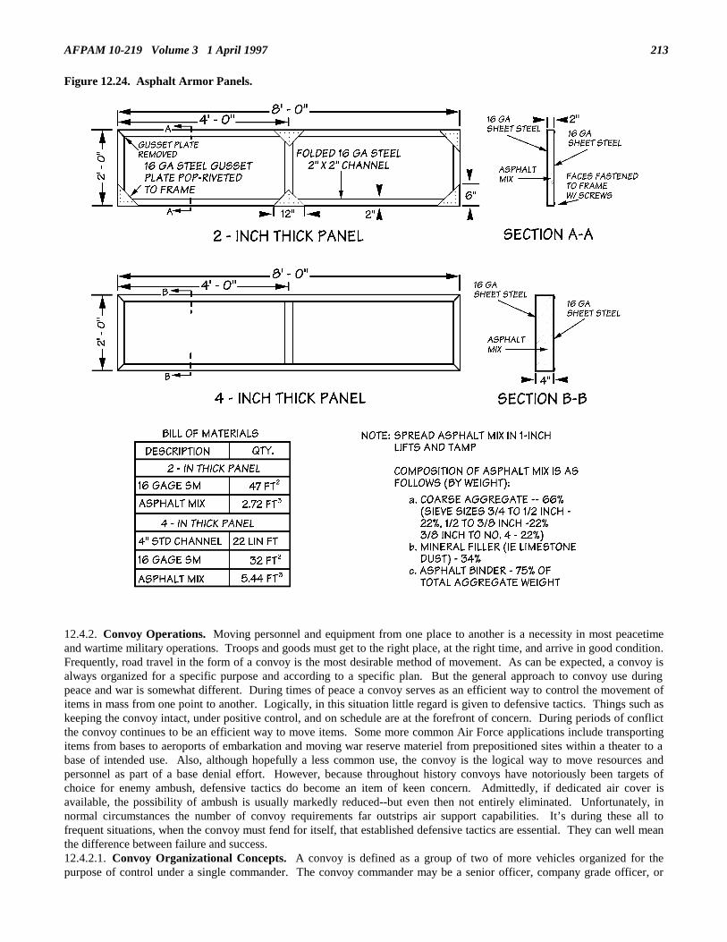
AFPAM 10-219 Volume 3 1 April 1997 213
Figure 12.24. Asphalt Armor Panels.
12.4.2. Convoy Operations. Moving personnel and equipment from one place to another is a necessity in most peacetimeand wartime military operations. Troops and goods must get to the right place, at the right time, and arrive in good condition.Frequently, road travel in the form of a convoy is the most desirable method of movement. As can be expected, a convoy isalways organized for a specific purpose and according to a specific plan. But the general approach to convoy use duringpeace and war is somewhat different. During times of peace a convoy serves as an efficient way to control the movement ofitems in mass from one point to another. Logically, in this situation little regard is given to defensive tactics. Things such askeeping the convoy intact, under positive control, and on schedule are at the forefront of concern. During periods of conflictthe convoy continues to be an efficient way to move items. Some more common Air Force applications include transportingitems from bases to aeroports of embarkation and moving war reserve materiel from prepositioned sites within a theater to abase of intended use. Also, although hopefully a less common use, the convoy is the logical way to move resources andpersonnel as part of a base denial effort. However, because throughout history convoys have notoriously been targets ofchoice for enemy ambush, defensive tactics do become an item of keen concern. Admittedly, if dedicated air cover isavailable, the possibility of ambush is usually markedly reduced--but even then not entirely eliminated. Unfortunately, innormal circumstances the number of convoy requirements far outstrips air support capabilities. It’s during these all tofrequent situations, when the convoy must fend for itself, that established defensive tactics are essential. They can well meanthe difference between failure and success.12.4.2.1. Convoy Organizational Concepts. A convoy is defined as a group of two of more vehicles organized for thepurpose of control under a single commander. The convoy commander may be a senior officer, company grade officer, or

AFPAM 10-219 Volume 3 1 April 1997214
non-commissioned officer depending upon the size of the convoy. Overall, a convoy may be divided into serials and units.Basically, the convoy consists of all the vehicles involved in a single move over the same route. A serial is a subdivision ofthe convoy, and a unit is a subdivision of the serial. Small convoys, usually 20 vehicles or less, are not subdivided becausethis is a reasonable quantity that can that can be effectively controlled by a single commander.12.4.2.2. Elements of a Convoy. All convoys, regardless of size, have three parts, each of which has a job to perform.These parts are a head, main body, and trail. At times, it may be necessary to use a fourth part, the detached party, which issent out either ahead or after the column.12.4.2.2.1. Head. The head is the first vehicle of the column. The pace setter rides in this vehicle and sets the paceaccording to the speed that can be maintained by the slowest vehicle in the convoy. The officer or NCO at the head ensuresthat the column is following the proper route and checks at scheduled check points.12.4.2.2.2. Main Body. The main body of the column follows immediately after the pace setter. It consists primarily ofvehicles carrying troops, equipment and/or supplies.12.4.2.2.3. Trail. The trail is the last element of a convoy. The trail officer or NCO maintains discipline, prevent straggling,and check final clearance at designated check points.12.4.2.2.4. Detached Party. Detached parties are not considered part of the main column. They are detailed to performspecial duties such as reconnaissance. In some tactical situations, advance, flank, or rear guards may be required. Guides,escorts, and patrols may also be needed for heavily traveled roads and at busy intersections.12.4.2.3. Types of Column Formations. Three basic types of column formations are commonly used—close column, opencolumn, and infiltration. The difference in formation depends largely on vehicle spacing. Table 12.2 illustrates the key datarelating to the three formations.
Table 12.2. Column Formations.
FORMATION
TYPE
WHEN USED
VEHICLE
DENSITY/MILE
TYPICAL
SPEED
ADVANTAGES DISADVANTAGES
Close Night, PoorlyMarked Routes,Congested Areas
21 + 10 MPH Better Control, FewerGuides and MarkersNeeded
Easy Detection,Quick DispersalDifficult, Subject toCongestion
Open Daylight 11-20 15 MPH Less Chance ofObservation, Faster
Control MoreDifficult
Infiltration Daylight,Congested Areas
2-10 HighSpeedsPossible
Fastest, HighestSecurity
Control MostDifficult, RequiresExperienced Drivers
12.4.2.4. Convoy Command and Control. Control of convoys can be exercised in two basic ways. First , it can beexercised by the organization making the move. Second, it can be exercised by the commander of the area through which theconvoy will be conducted. Both situations sometimes occur together. Most Air Force engineer convoys should not beaffected by the second type of convoy control; all, however, will be governed by the first. Exercising organizational controlsimply means the supervisors and driver will follow speed limits and traffic laws, time and distance gaps, routing plans andschedules. Further organizational control can be exercised by designating personnel to perform various convoy support tasks.For example (remember, not all of these personnel may be necessary for every convoy movement; it is a case by casedecision):12.4.2.4.1. Convoy Commander. This individual, either an officer or NCO, is responsible for overall control and movementof the convoy.12.4.2.4.2. Pace Setter. This individual rides at the head of the convoy establishing the rate of speed necessary to maintainthe convoy’s schedule.12.4.2.4.3. Trail Officer. The trail officer (normally a transportation type) is positioned at the rear of the column and ischarged with correcting vehicle problems and ensuring any following traffic is properly warning when the column halts.Sometimes a vehicle maintenance technician accompanies the trail officer. If a convoy is deemed large enough to requirededicated transportation unit support, a support request should be submitted through channels (usually the survival recoverycenter).12.4.2.4.4. Advance Officer. This individual precedes the column and reconnoiters the route. He selects detours oralternate routes if necessary to avoid bottlenecks or battle damage. In addition, the advance officer may post guides ormarkers for the convoy to follow and clear convoy movement with local authorities.12.4.2.4.5. Advance Quartering Party. An advanced quartering party is sometimes used when a convoy is required tomove into a bivouac en route or at its destination. The advance quartering party can be used to accomplish the following:

AFPAM 10-219 Volume 3 1 April 1997 215
12.4.2.4.5.1. Clear and secure the site.12.4.2.4.5.2. Determine defensive positions.12.4.2.4.5.3. Layout key locations (parking areas, command post, storage sites, etc.).12.4.2.5. Security Police Interface. The degree of security support necessary will, for the most part, be driven by the actualand anticipated threat in the area of travel. It is desirable that all engineer convoys to remote or off-base areas beaccompanied by a security police or military police escort if a Level I threat or higher exists. During a conflict or after a baseattack all convoy operations must be cleared through the base defense operations center (BDOC). Initial coordination may bearranged by the survival recovery center (SRC). Decisions regarding convoy support will come from the BDOC. Thepotential of receiving an armed escort will depend upon the overall security situation at the time and the availability ofsecurity forces. Due to the possibility that an escort may not always be provided, engineer forces must be prepared to take onthis task themselves as part of their defensive training.12.4.2.6. Convoy Planning. Normally the planning coordination involved in a convoy operation has to be accomplishedquickly since the convoy commander has only a limited period to reconnoiter the route, brief personnel, coordinate withsecurity forces, marshal and inspect equipment, and prepare logistics support. Obviously one of the first steps that must betaken is to select the route the convoy will follow. It is good practice to look for alternate routes as well to permit flexibilityat the last moment and during the move. If the convoy is to travel a commonly used convoy route, gather information such astravel times from point to point, locations of halt/rest areas and refueling locations. Check with Security Police andTransportation personnel for data. Once a route is chosen, coordinate the convoy requirement with the BDOC. The BDOC,in turn, will determine whether an escort can be provided and inform other security organizations in the area of the convoyrequirement. It is also a good idea to obtain the current intelligence estimate to verify threat conditions and identify types ofpotential enemy forces.12.4.2.6.1. Route Reconnaissance. At a minimum the convoy commander should make a map reconnaissance whichbasically entails checking available maps for terrain features, towns, bridges, choke points and any other sites that could causedifficulties for convoy movement. If time permits, the convoy commander and selected supervisory personnel should conductan actual ground reconnaissance of the route to see firsthand how these features might impact convoy progress. Not only willthis ground run familiarize key personnel with the route, but it will also identify factors not apparent from a map, e.g., roadconditions, vertical obstructions such as wires and signs, actual sizes and precise locations of servicing facilities, travel times,and potential ambush sites. If available maps are poor or scarce, “home-made” strip maps are often created. These simplifiedmaps provide a total picture of the convoy route showing assembly areas, start and end points, halt/rest areas, major roadintersections, natural landmarks, and danger areas. Usually each convoy driver receives such a map.12.4.2.6.2. Food Service Support. If drivers and troops are expected to remain effective, they must have food and water.Your plans must consider this factor. It is unlikely that engineer forces will be at a remote work site where field bivouacprocedures would have to be followed for an extended period. Most of our tasks would have a duration of less than a fewdays and it is probable that we would not be far enough away from an Air Force installation to preclude daily round trips.Plan on using ready-to-eat meals (MRE) for those occasions where messing must be provided during the convoy or at worksites. Also plan on having to haul water with you using either water trailers or large coolers.12.4.2.6.3. Convoy Organization. After gathering route, security, and logistics information, the convoy commander shouldhave enough data to enable preparation of a convoy organization plan. Local conditions will dictate the details; however, thefollowing should be considered under most circumstances:12.4.2.6.3.1. Vehicle Deployment. When assigning positions to vehicles within the column, special attention should begiven to vehicles loaded with ammunition and POL supplies. Do not place vehicles loaded with critical cargo close together,disperse them throughout the convoy.12.4.2.6.3.2. Control Vehicles. Control vehicles, especially the convoy commander’s, are priority targets for an ambushforce. By taking these vehicles out of action at the onset of an attack, key leaders are eliminated. However, an ambush forcecan be placed at some disadvantage if there is no set pattern in the location of control vehicles. Further deception may comefrom using a cargo vehicle with radios installed as a command vehicle. Keep these factors in mind if repeated trips to a worksite are planned over a few days.12.4.2.6.3.3. Maintenance and Recovery Vehicles. These types of support vehicles probably will not be assigned to anconvoy unless it is large, e.g., a base denial operation. Most engineer convoys will be less than 10 vehicles and therefore willhave to fend for themselves in terms of vehicle recovery. Consider carrying tow bars, straps, chains, or ropes to tow disabledvehicles to the work site or back to base. Normally an entire convoy is not halted when one vehicle breaks down. A secondvehicle is used as a recovery vehicle and the rest of the convoy moves on. While the disabled vehicle is being attached to therecovery vehicle, any passengers involved take up defensive positions around the vehicles.12.4.2.6.3.4. Armed Escort Vehicles. The decision on the location of escort vehicles is usually made by the escort element(security police) leader. Normally one escort vehicle should be located near the head of the convoy so that heavy weaponsfire can be brought on enemy personnel quickly. The remaining escort vehicles are located where they can provide maximumprotection for all elements. Since it is easier for vehicles to move forward, some escort vehicles must be positioned in the rearof the element to which they are attached.
AFPAM 10-219 Volume 3 1 April 1997216
12.4.2.6.4. Convoy Halts. Halts are made for rest, personal comfort and relief, messing, refueling, maintenance andinspection of equipment, and schedule adjustment while allowing other traffic to pass. Short distance convoys probably won’trequire any halts, whereas longer distances will make halts a necessity. The selection of halt locations should be made beforethe departure of the convoy. Short halts will normally last 10 minutes and take place about every two hours. Longer halts fordining, refueling, and bivouacking must always be a part of the road movement schedule. When the situation permits, diningand refueling halts should coincide. Normally, all elements of a convoy halt at the same time so that gaps between vehiclesstay the same. During halts all personnel have certain responsibilities. Officers and NCOs check the welfare of the personnel,the security of loads, vehicle operation, and the performance of any required operator maintenance. The choice of haltlocations requires special attention and this is why they are selected in advance. The following are some factors to considerwhen choosing halt locations:12.4.2.6.4.1. Choose locations that are in a relatively secure place and, when possible, under the watchful eye of a securityforce.12.4.2.6.4.2. Halt the convoy at points where you can see 200 yards from the head and tail of the column.12.4.2.6.4.3. Avoid restrictions, curves or grades and pull vehicles as far off the road as possible.12.4.2.6.4.4. Always maintain the prescribed vehicle distance.12.4.2.6.4.5. Never stop in towns or cities without a specific purpose.12.4.2.6.4.6. Avoid scheduling halts in areas where there is a lot of vehicular or pedestrian traffic.12.4.2.6.4.7. Keep civilians away from the convoy.12.4.2.6.4.8. Always post guards at the front and rear of the convoy and at any other point that may cause hazards to passingtraffic.12.4.2.6.4.9. Select halt areas that are defensible and provide cover and concealment.12.4.2.6.4.10. Choose places with good drainage and a surface that will support the convoy’s vehicles.12.4.2.6.4.11. Allow space for vehicle, equipment and personnel dispersal.12.4.2.6.5. Vehicle Spacing and Speed. As a general guide vehicle spacing should be 50 meters (approximately 160 feet) inurban areas with heavy traffic and 100 meters (approximately 325 feet) on the open road. Convoy speed will depend on thecondition of the road and traffic and on the speed of the slowest vehicle. Usually convoy speeds will be in the 15-30 milesper hour range. Whatever the established speed, it must be controlled throughout the term of the convoy by the pace setter(lead vehicle).12.4.2.6.6. Convoy Scheduling. Once the start time, start and end points, routes, and planned halts have been determined,the next step is to schedule the move on a time line. Using the planned speeds over the various portions of the route and routedistances, a schedule is developed which indicates when the convoy is to arrive at each key checkpoint/halt location and itsfinal destination. This information should be placed on the strip maps provided to the drivers and to the BDOC so it will havean estimate of the convoy’s location at any point in time in case an armed escort is unavailable.12.4.2.6.7. Final Convoy Preparations. With all planning and coordination completed, the convoy is almost ready to move.Final preparations include physically organizing the order of the convoy, briefing personnel, and inspecting individualequipment and vehicles. Although all elements in a convoy do not have to start from the same spot, this will normally be thecase with engineer convoys. Organizing the convoy is a mechanical process of placing the head and trail vehicles properly,correctly interspersing critical vehicles within the column, and properly locating escort vehicles. Briefing of convoypersonnel is extremely important. Personnel should be informed of convoy duration, number of halts planned, identificationof key supervisory/command personnel, and potential security threats enroute. Lastly, equipment and vehicles are given afinal check. Radio operation between vehicles and with the base station is verified. All vehicles are inspected for mechanicalsoundness and security of loads. If a vehicle with faulty operation is found, replace it--don’t take it on the move. As yourconvoy moves out, let both the damage control center and the BDOC know.12.4.2.7. Convoy Standard Operating Procedures. If your unit finds itself having to perform convoy operations on arelatively routine basis, a set of standard operating procedures should be established. These procedures will act as a checklistand answer many of the questions that commonly arise during convoy planning sessions. The procedures should includeinformation on the following and be modified as appropriate for local conditions:12.4.2.7.1. Duties of convoy command and control personnel.12.4.2.7.2. Standard convoy organization.12.4.2.7.3. Weapons and ammunition to be carried.12.4.2.7.4. Vehicle hardening actions and when to use them.12.4.2.7.5. Protective equipment to be worn.12.4.2.7.6. Actions during scheduled halts.12.4.2.7.7. Maintenance and recovery of disabled vehicles.12.4.2.7.8. Refueling and rest halts.12.4.2.7.9. Communications procedures.12.4.2.7.10. Convoy notification requirements.12.4.2.7.11. Strip map development.

AFPAM 10-219 Volume 3 1 April 1997 217
12.4.2.7.12. Route reconnaissance.12.4.2.7.13. Preparation of convoy vehicles, e.g., loading, camouflaging, etc.12.4.2.7.14. Counter-ambush operations.12.4.2.8. Convoy Defensive Measures. In an Air Force convoy, security is the responsibility of the escort force. When acombat emergency arises, the escort commander/leader assumes operational control of the convoy until the crisis is over.Normally, the escort force will take all the necessary action to neutralize the ambush while the convoy escapes the immediatearea. When the enemy has been dislodged, the road must be cleared and proper convoy movement resumed as soon aspossible. When disabled vehicles cannot be towed, their cargo should be distributed among other vehicles if time permits. Ifsuch is not possible, it normally will be destroyed upon an order from the convoy commander. When possible, radios andother critical items will be recovered before the destruction. Lastly, remember engineer personnel act in a defensive roleonly; we are not trained to maneuver or engage an enemy force in an offensive mode. Leave that task to the escort or armedreaction force.12.4.2.8.1. Ambush Defense--Road Not Blocked. Due to the extensive road space occupied by a normal convoy, andbecause security or lack of available forces usually limits the size of an ambushing force, this force is seldom able to containan entire convoy in a single kill zone. More frequently, a part of a convoy, either the head, trail, or a portion of the mainbody, is ambushed. That part of a convoy which is in the kill zone and receiving fire must drive out of the ambush if the roadto the front is open. Vehicles disabled by enemy fire are left behind or, if blocking the road, must be pushed out of the way bythe following traffic. Vehicles which have not entered the kill zone must not attempt to do so. If an escort force is presentwith the convoy, it will normally attempt to defeat or drive off the ambush force. Engineer personnel in vehicles which havenot entered the ambush area, will dismount (see figures 12.25 and 12.26 for typical dismount formations) and take updefensive positions. These personnel, however, will not fire without coordinating with the escort force first. If an escort forceis not present with the column, vehicles which have not entered the ambush area should leave the area and proceed to a pointof known security even if this means returning to home base. Regardless of whether an escort force is present or not, a callback to home base informing command personnel of the situation and requesting armed assistance is appropriate.

AFPAM 10-219 Volume 3 1 April 1997218
Figure 12.25. Right Dismount (Three Fire Teams).
Figure 12.26. Left Dismount (Three Fire Teams).
12.4.2.8.2. Ambush Defense – Road Blocked. When an element of a convoy is halted in the kill zone and is unable toproceed due to disabled vehicles, a damaged bridge or other obstacle, personnel caught in the kill zone should dismount, takecover, and return a maximum volume of fire on the enemy position. An immediate call for armed reaction force assistance
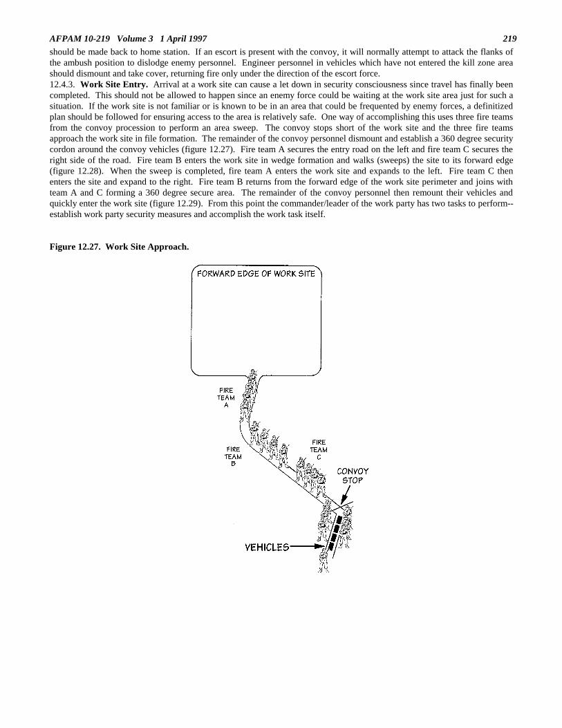
AFPAM 10-219 Volume 3 1 April 1997 219
should be made back to home station. If an escort is present with the convoy, it will normally attempt to attack the flanks ofthe ambush position to dislodge enemy personnel. Engineer personnel in vehicles which have not entered the kill zone areashould dismount and take cover, returning fire only under the direction of the escort force.12.4.3. Work Site Entry. Arrival at a work site can cause a let down in security consciousness since travel has finally beencompleted. This should not be allowed to happen since an enemy force could be waiting at the work site area just for such asituation. If the work site is not familiar or is known to be in an area that could be frequented by enemy forces, a definitizedplan should be followed for ensuring access to the area is relatively safe. One way of accomplishing this uses three fire teamsfrom the convoy procession to perform an area sweep. The convoy stops short of the work site and the three fire teamsapproach the work site in file formation. The remainder of the convoy personnel dismount and establish a 360 degree securitycordon around the convoy vehicles (figure 12.27). Fire team A secures the entry road on the left and fire team C secures theright side of the road. Fire team B enters the work site in wedge formation and walks (sweeps) the site to its forward edge(figure 12.28). When the sweep is completed, fire team A enters the work site and expands to the left. Fire team C thenenters the site and expand to the right. Fire team B returns from the forward edge of the work site perimeter and joins withteam A and C forming a 360 degree secure area. The remainder of the convoy personnel then remount their vehicles andquickly enter the work site (figure 12.29). From this point the commander/leader of the work party has two tasks to perform--establish work party security measures and accomplish the work task itself.
Figure 12.27. Work Site Approach.
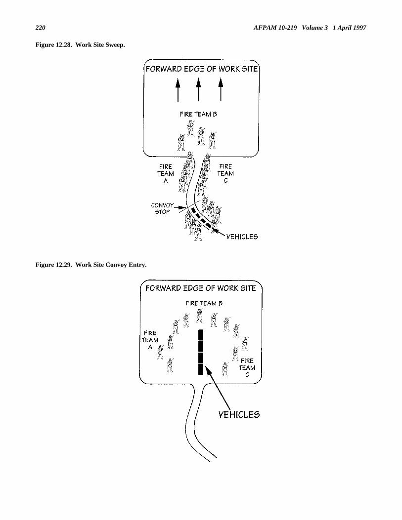
AFPAM 10-219 Volume 3 1 April 1997220
Figure 12.28. Work Site Sweep.
Figure 12.29. Work Site Convoy Entry.

AFPAM 10-219 Volume 3 1 April 1997 221
12.4.4. Work Party Security. In a Level I or II threat environment, work party security is provided by two or threeindividuals posted on the perimeter of the work area to provide early warning of any impending hostile action. If the workparty is fired upon; these individuals will determine the direction of fire; estimate the type, size, and apparent intent of thehostile force; direct the work party to take defensive cover and call the security police for assistance (an armed reactionforce). Defensive cover, as used in this context, means the occupation of either hasty or deliberate (prepared in advance)defensive positions that take maximum advantage of the terrain at or in the vicinity.12.4.4.1. Defense Sectors. Upon arriving at a work site, establishing proper security requires more than just posting guardsat arbitrarily selected locations. To best defend the entire work site, defense sectors should be established. This task requiresseveral actions to be taken. The first action is to establish the exact boundary of the work site. Once this is done, the workparty leader/commander and personnel who will be serving as sector commanders walk the perimeter of the work site andestablish sector boundaries. Normally the number of sectors is kept between three and five and the sectors need not be all thesame size. The size of the sector will depend on the terrain and what resources are within the sector. The important thing tobe sure of when setting up sectors is that the boundaries between sectors are well defined. This allows personnel defending asector to know exactly where their terrain defense responsibilities start and end. Once sector locations and boundaries aredetermined, sector commanders site fighting positions in locations that have clear lines of fire toward the work area perimeter.These positions should be at least the equivalent of a hasty fighting position. If the work site will be occupied continuouslyfor several days or longer, consideration should be given to constructing deliberate positions. Manning of the sector fightingpositions should be by pre-established fire teams if possible--this maintains team integrity and pre-identifies a leader “in thetrenches”.12.4.4.2. Listening Posts. The purpose of going to a work site is to accomplish an engineer construction task of some sort.Security, while obviously important, cannot be allowed to consume most of your resources all the time. Normally, a smallnumber of troops are placed on security duty while the remainder perform the engineering task. These security troops will notbe sufficient to man all the fighting positions; but a “trip wire” system of using listening posts can be used. These listeningposts are positioned outside of the work site perimeter but close enough to allow individuals to quickly return (figure 12.30).If an enemy force is encountered, the troops manning the listening posts bring the information back to the work site, fightingpositions are manned, and security police support is immediately requested.
Figure 12.30. Sectors, Fighting Positions and Listening Posts.
12.4.5. Air Base Defense. The security police have the primary responsibility for air base defense and many of the itemsdiscussed earlier are applicable in this task. In addition, engineers have a responsibility in air base defense both from asecurity aspect and a construction viewpoint.12.4.5.1. Fundamentals of Air Base Defense. The concept for air base defense is to use security police, other selected AirForce personnel (e.g. Prime BEEF, augmentees, etc.), and other US Service and host nation forces to detect and engageenemy forces that threaten air operations. From a threat perspective Air Force personnel must be able to defeat Level Ithreats, defeat (or delay until assistance arrives) Level II threats, and delay Level III threats until major tactical combat units(e.g., US Army) can respond and assist. The area of operations encompassing air base defense does not necessarily end at thebase perimeter. In most cases it will extend outward from the installation; distances are normally determined throughagreements with off-base US and host nation forces.12.4.5.2. Air Base Defense Organization and Equipment. When in a contingency or wartime posture, the basic securitypolice defense team is the air base defense flight. This flight has a five-man headquarters element and three 13-man air base

AFPAM 10-219 Volume 3 1 April 1997222
defense squads (figure 12.31). Supplementing this flight are several teams with specialized capabilities such as 81 MMmortar operation, 50-caliber machine gun operation, 40 MM grenade launcher operation, fire direction, and military workingdog handling. The basic security police flights and security police specialized teams form the backbone and most of themuscle of the on-base air base defense organization.
Figure 12.31. Air Base Defense Flight (Headquarters and Squad).
12.4.5.3. Air Base Defense Planning. There are many aspects of air base defense planning, but we will only address thosethat have a bearing on engineer operations. Two major air base defense planning items that involve engineer personnel arethe air base vulnerability analysis and base sectorization.12.4.5.3.1. Vulnerability Analysis. The security police conduct a vulnerability analysis of the air base as one of their firsttasks of air base defense planning. This analysis identifies unit missions and mission critical resources, prioritizes theseresources, and addresses protection options. Information from this analysis is used by the security police commander toallocate air base defense forces. As part of this analysis base units are asked to identify what parts of their operation arecritical, what are the relative priorities of these parts, are there any single point failure nodes, how would they attack them anddefend them, and how fast can the parts be replaced. Do your homework here--identify to the security police your base’scritical engineer related resources. These could include, but not be limited to, major utility nodes and plants, recoverymaterial stockpiles, rapid runway repair equipage, and command and control centers. When all base critical resources havebeen identified and prioritized, methods of protection are determined. These methods could range from dispersal,camouflage, and area lighting to owner/user sentries, roving patrols, and manned fighting positions.12.4.5.3.2. Sectorization. The security police will normally divide the base into sectors, each containing a generally equalshare of the critical resources identified through the vulnerability analysis. Once sectors are established, air base defenseflights are allocated. Usually these security police flights are assigned to critical resources first, then to the defense of thetactical perimeter of the base. Engineer personnel should plan on having to support the sectorization process by assisting inthe construction of deliberate fighting positions, clearing fields of fire, and constructing and placing obstacles. See volume 2of this pamphlet series for construction details.

AFPAM 10-219 Volume 3 1 April 1997 223
12.4.5.4. Augmentation of the Air Base Defense Force. Air base defense doctrine, as outlined in AFI 31-301, Air BaseDefense, calls for the employment of base units to augment the security police air base defense effort. The degree ofparticipation is predetermined in a base defense plan (an outcome of the vulnerability analysis). Normally engineer forceswill be assigned to protect an engineer resource (owner/user security) or augment in a specific sector. Augmentation timingwill be determined by the base or wing commander and a “stop work” ordered issued, probably verbally. At this timeengineer personnel will secure their equipment, gather weapons and take up security positions. When performing in the basedefense mode, engineer personnel will normally be placed under the control of the security police commander. Detailedprocedures for engineer units supporting an air base defense effort should be prepared and included in Annex C to the CivilEngineer Contingency Response Plan.12.4.5.5. Owner/User Security. In plain terms, owner/user security involves using a unit’s own resources to protect itsessential facilities and equipment assets. Good pre-planning and training are necessary to ensure engineer response to a threatto base security is timely and organized. Personnel should be informed of exactly where to report and what to do. An officershould be placed in charge engineer fire teams and maintain constant contact with security police representatives. Shiftsshould be established and checks should be made on all manned positions at least hourly by supervisory personnel. Plan onmanning all defensive positions with two personnel each and provide all personnel manning these positions with the followingminimum information.12.4.5.5.1. Location of shift leader and how to make contact.12.4.5.5.2. Expected/probable direction of enemy attack or infiltration.12.4.5.5.3. Area of responsibility, i.e., what ground to watch over.12.4.5.5.4. Location of adjacent posts.12.4.5.5.5. Location of listening posts if forward of defensive position.12.4.5.5.6. Location of friendly forces forward of defensive position if any.12.4.5.5.7. Procedure for challenging (work closely with security police on rules of engagement and techniques).12.4.5.5.8. Password and password change times (coordinate with security police on use of recognition codes).12.4.5.5.9. Shift change times and procedures.
12.5. Antiterrorism Planning. Terrorism has become a tactic for projecting national power. The use of fear and terror tosway political opinions, to lower morale, or to attack a larger force has become commonplace throughout the world. Terroristorganizations that act in a peacetime environment use violence for effect, seeking to influence as large an audience aspossible. These terrorists will use the attack to discredit a government and, at the same time, gain popular support. Mostterrorist operate from a “cell” concept, a small secretive group supported by a portion of the local population. Such supportfrom the civilian population is obtained either willingly or under pressure and is critical to the existence of the terrorist group.When a hostile nation uses terrorism as a tool of warfare, it generally considers terrorist acts as legitimate military operations.12.5.1. Tactical Terrorism. Tactical terrorism adds a tremendous dimension to the battlefield and places an air base high onthe list of potential targets. Several countries and groups hostile to U.S. national interests, still subscribe to the Cold Wardoctrine that terrorism is a viable means to obtain tactical, operational and strategic objectives. This doctrine prescribes theuse of highly trained forces for bombings, assassinations, arson and other terrorist-type tactics to strike critical targets in ourrear area. They will seek to attack when and where we least expect it or are least prepared. Their attacks will be irrelevant ofthe specific time any hostilities may be declared, but their objectives will support future military actions. The terrorist is ahighly motivated, skilled individual, dedicated to his cause and may be willing to die for that cause. The terrorist is success-oriented. Before planning antiterrorism measures for an air base, let’s reverse roles and review the terrorist planning factors.12.5.1.1. Mission. The mission will be against specific targets in the enemy’s area. The primary goal, unlike a militaryattack, is to generate fear and psychological instability. The attacks are designed to create an attitude of defeat through fearand the apparent “helplessness” of defending against such an attack. The target can be any individual, unit, facility, or anentire installation that may generate this terror.12.5.1.2. Enemy. The enemy is anyone or anything connected directly to the allied or U.S. forces. The terrorist may attacklucrative civilian targets, or even noncombatants during evacuation. Military targets will include general officers,commanders, command posts, airfields, ports, railheads, and critical storage facilities. The terrorist’s tactical goal is thedeterioration of morale and confidence among U.S. forces--“the more dead, the better the effect.” The more heinous theattack, the greater the impact of fear. The attacks may also cause our forces to commit resources to protect potential targetsduring a resource intense period.12.5.1.3. Terrain. The terrorist will always try to use terrain to his best advantage. It will be the terrorist’s decision ofwhere and how to attack, so he will carefully analyze the terrain and watch for the easiest access. Facilities with large militarypopulations or equipment of strategic value are preferred as targets. Poor security and complacency will give the terrorist anopportunity for success.12.5.1.4. Attackers. The most skilled terrorist will be selected for the attack. Their intelligence will be excellent and theirprocedures will be extremely well rehearsed. They will patiently train the individual terrorist or team to ensure success.Success at all costs.

AFPAM 10-219 Volume 3 1 April 1997224
12.5.1.5. Time. Time is the greatest ally of the terrorist. He will select his target and attack at the weakest moment. In mostcases the mission would not be time dependent. If it is, the procedures would be developed using accurate intelligence bypersonnel constantly surveilling the target. He will always use time to his best advantage. Consider the timing in the attackagainst the U.S. Marines in Beirut, Lebanon. It took place on a Sunday. The terrorist logic was to use Sunday, a day ofChristian worship and rest (when security may have been relaxed), as a psychological tool to gain shock action, fear, andsuccess.12.5.2. Antiterrorism Measures. Although vastly different in purpose, air bases share many of the terrorist risksexperienced by the ill-fated Marine Corps installation in Lebanon. As with the Marines, air base operations are likely to takeplace in high risk overseas areas during periods of heightened regional, or even world tension. High value aircraft, commandand control centers, storage facilities, and a large number of U.S. service personnel concentrated in a single location make anair base operation a key terrorist target. Aside from the physical damage inflicted, a successful act of terrorism against aUSAF deployment site would gain the terrorist group and their cause worldwide publicity. The unpredictability of theterrorist threat calls for the preplanning of both passive and active countermeasures.12.5.2.1. Passive Countermeasures. The dispersal of assets, hardening of critical facilities and utilities, and theconstruction of personnel protective shelters are addressed in detail in chapters 3, 4, and 5 of volume 2 of this pamphletseries.12.5.2.2. Active Countermeasures. In addition to dispersal, hardening, and protective shelter construction, you should planactive countermeasures to reduce the terrorist threat potential. Recent acts of terrorism provide some valuable lessons.Although terrorists employ a variety of tactics, clearly the most favored is bombing. Almost 70 percent of all incidentsrecorded in the last 20 years involved explosives. As experience shows, the preferred delivery means appear to be the vehiclebomb; typically, a vehicle filled with hundreds of pounds of explosive which either is parked in the immediate vicinity of thetarget or rapidly driven into the target to achieve an element of surprise. However, if terrorists bent on a suicide missionwhile enroute to the objectives can be delayed (and if the delay is long enough), the terrorists can be killed or captured andtheir mission will fail.12.5.2.2.1. Obstacles. Several types of obstacles can be built or emplaced to hinder terrorist movements and access topotential targets. Included in these types would be steel hedgehogs; concrete cylinders, cubes, and tetrahedrons; earth berms;concertina wire; and ditches. Details on obstacle construction and placement can be found in chapter 8 of volume 2 of thispamphlet series.12.5.2.2.2. Shielding. Despite their proven effectiveness, obstacles by themselves will not completely defeat the terroristthreat at an air base. However, shielding a potential target from terrorist view will reduce the risk considerably. Terroristswant the “biggest bang for the buck”--in other words--they are reluctant to waste their effort on a target of uncertain value.Shielding valuable assets from terrorist view can take many forms ranging from concealment and camouflage to elaboratedeception measures. For example, a sandbag wall of sufficient height will not only screen a critical facility from view, butalso serve as protection from conventional munitions. Likewise, camouflage netting used to conceal air base assets fromenemy aerial detection can be used very effectively to screen the view of a ground level terrorist reconnaissance observer.Check chapter 6 of volume 2 of this pamphlet series for other shielding methods.12.5.2.3. Other Basic Considerations. Finally, there are some very basic guidelines for dealing with the terrorist menace:12.5.2.3.1. Expect the unexpected.12.5.2.3.2. Always assume an attack will occur. Weapons, helmets and flack vests should be readily available or worn, asrequired.12.5.2.3.3. Don’t become predictable in your operation; change schedules and routines frequently.12.5.2.3.4. Use an overwatch observer system for remote, exposed work sites and change work party travel routes frequently.12.5.2.3.5. Above all, do not allow fear to dominate or reduce morale; use it as an advantage to instill a heightened sense ofsecurity awareness among the air base population.
12.6 Summary. This chapter has presented some basic facts and procedures relating to the engineer’s role in air basesecurity. The threat level affecting U.S. Air Force bases was reviewed and the responses required by Air Force personnel tothese threats was presented. Major aspects of personal security were addressed to include cover, camouflage and concealmenttechniques and individual movement procedures. These features were then expanded to discuss small group movement byfire teams, the construction of basic fighting positions, and communications. Convoy operations were then addressed toinclude organization, command and control, planning, and defensive techniques. The chapter then graduated to work partysecurity methods with portions discussing area entrance procedures and development of sectors and listening posts. Thistopic was followed by an explanation of the engineer’s role in air base defense. Major emphasis was placed on the closecoordination and cooperation required with the security police. Lastly, a brief discussion on the terrorist threat to air baseswas presented and ways of hindering these activities were outlined.
AFPAM 10-219 Volume 3 1 April 1997 225
Chapter 13
BASE DENIAL
13.1. Introduction. Denial operations always affect the conduct of war and, on occasion, may attain paramount importance.Historical examples include Sherman’s march to the sea through Georgia, the Union campaign to close the Mississippi duringthe Civil War, the Russian scorched earth policy, the allied strategic bombing campaign of German industry in World War II,and the destruction of Kuwait’s oil wells by Iraq during the Gulf War. However, the United States conducts combatoperations in accordance with its law of war obligations. It takes all reasonable precautions to minimize incidental injury touninvolved civilians and avoid unnecessary damage to civilian objects. The French diplomat Talleyrand explained this policyin a letter to Napoleon: "Nations ought to do to one another in peace the most good, in war the least possible evil". The lawsof war require that denial operations, particularly against civilian facilities and resources, be very carefully considered andthat execution authority be maintained at the highest levels of command. Denial actions prevent or hinder enemy occupationof, or benefit from, areas, objects and resources having tactical or strategic use. Therefore, they vary widely in scope. At oneextreme, an entire area is made useless to the enemy. At the other extreme, a specific area or facility, such as an air base isdenied to the enemy. A recent example of this latter situation is the RED HORSE demolition activity during the 1991 GulfWar at two captured Iraqi air bases.
13.2. Overview. For the main operating base (MOB) civil engineer, a denial responsibility includes all militarily significantcivil engineer supplies and equipment, base facilities and utilities, and the airfield pavement system. For BCEs at collocatedoperating bases (COBs) and bare bases, only USAF organic equipment is normally considered, since real property facilitiesand utility systems are a host nation responsibility. This chapter provides guidance on conventional denial procedures to beused at a deployed location. Non-explosive destruction methods are suggested for each of the basic civil engineer areas ofresponsibility. This chapter does not address denial operations at captured locations or specially identified targets--thesetypes of missions are normally a RED HORSE task and will generally have a narrower scope of activity.
13.3. Base Denial Considerations. Because air bases have not normally been highly threatened in previous conflicts, denialof an air base to enemy forces is an undertaking largely unfamiliar to the U.S. military. However, modern warfare and theforward locations of many air bases now make the requirement for base denial a possibility. Engineer forces will play a majorrole in such activities since they control significant amounts of equipment and supplies useful to an enemy and are mostfamiliar with the utility and facility aspects of any installation. Furthermore, the explosive demolition expertise residentwithin an engineer squadron makes the unit especially capable in base denial activities. Base denial actions are not haphazardevents, however. They require considerable pre-planning and everyone’s support if they are to be carried out effectively andall personnel are to leave the air base in an orderly, safe manner.13.3.1. The theater commander will describe the policy and extent to which denial operations are carried out. Denial of keyinstallations and facilities is desirable in most situations. Selected denial targets are integrated into the overall strategic andtactical concepts of the theater operations plan and are executed in accordance with war objectives. Actual denial activitieswill not start until directed by the wing commander and only after consideration has been given to future use of the air base byU.S. forces and what the impacts might be of the use of the air base by enemy forces. Taking it with you when you leave(evacuation) is the preferred method of denial and should be used when conditions permit. That which must be abandonedmust be denied to the enemy.13.3.2. Targets for base denial can come in many forms and one must be selective in choosing which targets to address. Basedenial carried to the extreme would remove or destroy everything that could aid the enemy in any way (figure 13.1).Attempting to destroy an entire air base, however, would be an extremely time consuming task and probably beyond thecapability of the normal wartime complement of engineer forces at an air base anyway. Besides matching manpower and timeconstraints against the scope of the overall denial task, the means selected to deny the intended target should be reasonablyavailable and produce the most damage possible. Targets for base denial could include heavy equipment, fuel supplies, keybuildings, utility substations, airfield pavements and classified materials, to name a few. And, each of these could require adiffering mode of destruction. In executing the base denial responsibilities, the BCE’s denial targets should meet the test ofone of these criteria:

AFPAM 10-219 Volume 3 1 April 1997226
Figure 13.1. Total Facility Denial.
13.3.2.1. Require the enemy to divert significant engineer and operational efforts for repair, reconstruction, or rehabilitationto resume flying operations, or other priority missions.13.3.2.2. Prevent the use of abandoned materials, supplies, and equipment to reinforce or augment the enemy’s combatcapabilities.13.3.3. Once base targets meeting the above criteria are chosen, they must be placed in a priority sequence for denial actions.This priority listing is important since time will probably be limited for base denial activities and it must be certain that themost crucial actions be accomplished initially, i.e., those actions which cause the greatest degree of resource denial should beperformed first. The priority listing must also take into account the interface and timing between denial actions. If these arenot considered, serious problems could result which could interrupt and hinder the entire base denial effort. For example, fuelstores could be destroyed before evacuation vehicles are fully serviced, traffic routes used by other denial teams could beblocked, or power could be cut off to those facilities being used to marshal and prepare equipment and supplies forevacuation.13.3.4. As mentioned earlier, removal and evacuation of resources is the preferred method of base denial. The reasons forthis are obvious--the resources are not harmed or damaged and they remain in U.S. Forces’ control rather than being lost forthe remainder of a conflict. Because evacuation operations will always be constrained by time and many agencies could bepotentially involved in the process, base denial must follow a thoroughly developed and well rehearsed plan that the BCEprepared in advance (see volume 1, chapter 3).
13.4. Conventional Base Denial Methods. There are four conventional ways of accomplishing base denial: itemevacuation, selective component removal, destruction, and the use of obstacles. Each method can have a place in the overallbase denial scenario. Because time to effect base denial will usually be short, attempt to use the procedure or procedures thatwill give the most rapid results with the least amount of effort.13.4.1. Evacuation. Always give serious considerations to removal of assets as a primary means of denial. Convoyingvehicles and heavy equipment to a safer location not only denies the equipment to the enemy but also keeps the resource aspart of our inventory (figure 13.2). In addition, it provides transportation for personnel and a means of relocating morecritical supplies away from the air base. Obviously, because of the logistics involved (fueling, marshalling, loading, etc.),most evacuation efforts should be started early in the scheme of things and follow a preplanned schedule.

AFPAM 10-219 Volume 3 1 April 1997 227
Figure 13.2. Asset Evacuation.
13.4.2. Component Removal. If evacuation of a key component is not possible, another excellent denial option is selectivecomponent removal. For example, by removing just the distributor cap on an engine you can render that item or equipmenttotally inoperative. Component removal can be a fast and easy means of denial; however, one word of caution is in orderwhen using this technique. Be sure to remove the same item(s) on all like items of equipment; otherwise, a creative opponentmay be able to cannibalize components from various different machines to make some operative again (figure 13.3). Lastly,do not forget to pick up any similar spares from bench stocks and supply points.
Figure 13.3. Like Item Component Removal.

AFPAM 10-219 Volume 3 1 April 1997228
13.4.3. Destruction. When using destruction as a means of denial, there are four primary methods employed: burning,soaking with water, mechanically damaging, and contamination. One non-conventional method of destruction commonlyincluded in many denial plans entails the use of explosives. However, due to the obvious dangers associated with handlingthis material, its use is normally restricted to specific personnel, namely explosive ordnance disposal (EOD) personnel.Although these personnel are part of a base’s civil engineer complement, they could be heavily tasked to support other baseagencies and may only be able to provide limited help in the civil engineer portion of base denial efforts. The use ofconventional, non-explosive methods of base denial will still remain the BCE’s primary means of accomplishing the basedenial mission.13.4.3.1. Fire. Destruction by fire is a good destruction technique for a wide range of materials and equipment. Heat canoften also be used in a selective fashion to deform or warp items that will not burn; bringing about dysfunction. Relativelythin gauge ferrous metals are often excellent candidates for this procedure. Even though fire seems from outward appearancesto be an ideal way of destroying facilities, this is not always the case. Modern building codes have brought about thedevelopment of a large variety of building materials that are highly fire resistant. Some of these less combustible materialsmay need to be thoroughly saturated with fuel in order to ensure ignition. As a result, it is always a good approach to consultthe fire department when destruction by fire is being considered. After all, they are the subject matter experts. A finalpossible negative point to consider when selecting fire as a destruction method is that the smoke normally generated fromlarge burning activities can serve to announce withdrawal intentions to an enemy.13.4.3.2. Water Soaking. Water can also be an effective means to damage many valuable assets. And, unlike burning, agreat advantage of using water is that it can be done quietly without revealing telltale signs of withdrawal intentions to anenemy. It is an excellent way of destroying electrical components. However, extreme caution must be used to avoidelectrocution when dealing with energized circuits. Water can also be used to contaminate a number of substances such aspetroleum fuels. In addition, many dry construction materials such as portland cement can be easily ruined by simplydrenching them with water (figure 13.4).
Figure 13.4. Water Damage.
13.4.3.3. Mechanical Destruction. This is another means which can be used to destroy assets without revealing withdrawalintentions to an enemy. Sledge hammers, axes, and wrecking bars are some of the more common tools of choice for thisdestruction technique.13.4.3.3.1. More often than not, mechanical destruction is conducted in a very selective manner rather than on a randombasis. Key components of an item of equipment such as control devices and gauges are usually where the emphasis is placed.A cutting torch can also be a useful tool when used judiciously. Properly trained personnel can use a torch to damage mainsupport members of metal structures such as buildings and bridges, eliminating or greatly hindering their designed use by anenemy. Though less common, large scale mechanical destruction methods can at times prove to be highly effective as well.

AFPAM 10-219 Volume 3 1 April 1997 229
This is particularly the case when large quantities of equipment or materials must be destroyed or damaged expediently. Insuch situations, heavy equipment can be used to crush items on a massive scale. In addition, burial can also prove to be anexcellent way of denying a resource to an enemy yet still allow its recovery by friendly forces at a future time.13.4.3.3.2. On the average MOB there are normally numerous systems and equipment that require lubricants or coolants forproper operation. Reciprocating engines can be made dysfunctional by simply draining these vital fluids and allowing them torun until they overheat and seize-up. Similarly, electrical distribution transformers can be quickly ruined by draining theircooling oil while the system is still energized. Lastly, the use of caustic substances such as sulfuric and nitric acid mayprovide yet another useful means of destruction denial, particularly when applied against electrical motors and electricalcomponents (figure 13.5).
Figure 13.5. Caustic Fluid Destruction.
13.4.3.3.3. Contaminating or adulterating substances may also be used to make many industrial items unusable. However,since no one substance is universally applicable, a technical knowledge of the denial target is a must. For example, sugar canwreak havoc with most reciprocating engines when placed in the fuel system. And, as was mentioned earlier, water can alsocause similar results when mixed with many petroleum based fuels.13.4.4. Obstacles. In addition to evacuation, component removal, and destruction, obstacles may be employed to deny theuse of certain facilities and resources to an enemy. Obstacles may be categorized as either natural or artificial. Due to thelayout of most air bases, your primary concern will focus upon the construction of artificial obstacles such as those shown infigure 13.6. Barbed wire entanglements are also effective personnel obstacles (figure 13.7). They may not completely stopenemy ground movement but, when coupled with the appropriate antipersonnel devices can hinder and greatly slow downtheir forward progress. Check with the security police on your base concerning the placement and installation ofantipersonnel devices; it is their responsibility to place these items. The use of more substantial obstacles, such as concreteand timber, can temporarily delay roadway access or even aircraft operations when applied to airfield surfaces. Dependingupon your location, there may be numerous other natural objects that may be employed to delay or even deny an enemy’saccess to your air base--as with many other Prime BEEF functions, creative thinking can be key to the success of your effort.

AFPAM 10-219 Volume 3 1 April 1997230
Figure 13.6. Typical Obstacles.
Figure 13.7. Barbed Wire Entanglement.
13.5. Base Denial Responsibilities and Techniques.13.5.1. General Information. Ensuring that individuals know and understand the methods of base denial is only the firststep in being able to perform this type of mission. Each individual must also know what his or her responsibilities might beand some of the more common techniques that can be used to physically accomplish the base denial task.13.5.1.1. Normally, not everyone in an organization will play a role in base denial. In fact, the vast majority of the basepopulation will usually be directed to evacuate before consequential denial actions commence. However, if time permits,base denial activities can be expanded to include a large percentage of the base population, but such situations would be theexception rather than the norm. Realistically, only a very limited number of personnel, those assigned and trained as membersof the base denial team, will remain behind to perform this vital role.13.5.1.2. The actual size and composition of the denial team will be dictated by a number of factors such as the amount of

AFPAM 10-219 Volume 3 1 April 1997 231
resources identified for destruction, types of items to be destroyed, and the methods of destruction to be employed. Manybase denial team assignments will be dictated by Air Force Specialties (AFS). For example, it only makes sense to haveelectrical personnel accomplish base denial actions on electrical systems since they are, as a matter of course, the ones that areintimately familiar with what type of action will best incapacitate the system. Likewise, the same parallel can be drawnbetween heating plants and HVAC (heating, ventilation, and air conditioning)/refrigeration personnel, airfield surfaces andpavements and construction equipment personnel, fuel systems and liquid fuels systems maintenance personnel, and fireprotection personnel and burning requirements. A good rule of thumb to follow when determining denial targetresponsibilities is to use the same areas of responsibility that exist under peacetime operations. In other words, if you arerequired to maintain or operate it during peacetime, also expect to be the one responsible for denying it to an enemy duringwartime.13.5.2. Base Denial--Pavement/Equipment Operations.13.5.2.1. Pavements and Construction Equipment personnel will be accountable for roadway, railway, drainage system, andairfield denial. Airfield pavements denial most often will be brought about through the use of a combination of obstacles andexplosives. However, the method employed and the extent of damage inflicted will to a large degree be dictated by how soonand even if we can anticipate regaining physical control of the property. If it is not unreasonable to expect to lose control ofthe assets for only a short period and enemy use of the airfield during that time will be insignificant to the total battle effort, itmay be counterproductive to extensively damage the airfield surfaces. The final decision to seriously deny use of airfieldpavements will be made at senior command levels and the BCE must verify the scope of pavement denial requirements beforeissuing orders to commence denial operations.13.5.2.2. Methods for performing denial of pavements, railways, drainage systems, and supporting equipment can takeseveral forms. The following are examples of various techniques that can be applied, singularly or in combination, to effectdenial actions.13.5.2.2.1. Use destroyed vehicles and aircraft, concrete blocks, or any kind of material that is readily available to createobstacles on the runway.13.5.2.2.2. Fill 55-gallon barrels with concrete and place them in the aircraft landing area of the airfield.13.5.2.2.3. If the airfield has an asphalt overlay, saturate selected areas with fuel to severely damage the surface area.13.5.2.2.4. Use heavy equipment such as bulldozers and pavement breakers to scar the surface of airfield pavements anddamage pavements at intersections and choke points.13.5.2.2.5. Place destroyed NAVAIDs, distance-to-go markers, and towers on the runway surface.13.5.2.2.6. Block open drainage ditches with rubble, debris, and rapid runway repair (RRR) fill material to cause floodingconditions.13.5.2.2.7. Use cement to block major drain areas and break primary drainage piping, particularly in those locations thatwould cause major airfield flooding.13.5.2.2.8. Destroy fiberglass and metal RRR matting by driving over it with a bulldozer until severe deformity occurs. Placethis damaged RRR matting on the airfield surfaces. Destroy any RRR component kits in the same manner.13.5.2.2.9. Intertwine barbed tape or concertina wire around any obstacles placed on pavement surfaces.13.5.2.2.10. Rip up railroad spurs with heavy equipment. Burn crossties and bend rails. Watch your timing on this item,however, since rail movement could be used as a means of personnel and equipment evacuation.13.5.2.2.11. Destroy and abandon on airfield surfaces any equipment not being evacuated by draining the oil and running theequipment.13.5.3. Base Denial--Electrical.13.5.3.1. Personnel in the electrical systems AFS will be responsible for destruction of the base power grid and its associatedsupport complexes. This will normally include primary and secondary distribution systems, major transformer substations,and airfield lighting systems. In addition, power production individuals will be responsible for denial activities involvingprime power plants, portable generators, and aircraft arresting systems. 13.5.3.2. Methods for physically accomplishing denial of electrical systems are relatively straight forward. Use sledgehammers to destroy regulators, transformers, insulators, gauges, and shop equipment. Use chain saws to cut utility poles andbarrier tapes. Vehicles and heavy equipment can be used to pull over towers (e.g., communications, radar, and GCA) anddestroy arresting barrier facilities. Generators and arresting barrier units can be destroyed by draining engine oil as the unitsare running. Lastly, key items in bench stocks, special levels, and war reserve materiel can be destroyed using some of thesame methods as above.13.5.4. Base Denial--Mechanical.13.5.4.1. HVAC/refrigeration personnel will be responsible for disabling all critical base mechanical systems. At sometheater locations this may also include cold storage and ice plant facilities. Liquid fuels system maintenance personnel shouldtake necessary steps to deny the use of both their system and product. The actual physical destruction of the pipeline itselfmay not be the easiest and most effective way of denying this crucial asset to an enemy. Instead, efforts should concentrate oncontamination of bulk storage supplies and the destruction of key distribution system control components such as automaticvalves and pumps.

AFPAM 10-219 Volume 3 1 April 1997232
13.5.4.2. Denial of mechanical systems is most easily done by physically destroying the components. Use sledge hammers tobreak coils, motors, condensers, pumps, gauges, heaters, cooling units, automatic valves, and system control devices. Usecutting torches to destroy boiler units, heavy metal, and spare parts. Contaminate bulk fuel storage facilities by adding water,used oil, or similar substances to the fuel supplies. Due to the extreme hazard posed by some liquid fuels, draining the fuelout of the storage tanks is not recommended. However, burning of tank farms upon evacuation from the base is a viabledenial method.13.5.5. Base Denial--Structures and Utilities.13.5.5.1. Structures and utilities systems personnel have the primary responsibility of destroying buildings and the water andsewage distribution systems. Structures individuals should obtain technical assistance from firefighting personnel in burningfacilities and any other bulk materials such as lumber and paint supplies. They should also use their skills with cutting torchesto damage metal support structures like bridges and aircraft shelter door rail systems. Utility systems personnel should directtheir effort toward disabling both the potable water and sewage distribution systems. Some of the key areas to concentrateupon here include deep well pumps, pumping stations, storage tanks, chlorination equipment, and sewage lift stations.13.5.5.2. Numerous methods of denying facilities and supporting utility systems are available. Some of the more useful onesinclude the following:13.5.5.2.1. Collapse facilities by using vehicles and cables to remove load bearing members.13.5.5.2.2. Use cutting torches to cut out supporting beams to buildings such as warehouses, aircraft hangers, andmaintenance areas.13.5.5.2.3. Use sledge hammers and jack hammers to break up bricks, concrete block, and concrete walls.13.5.5.2.4. Place debris in major drain areas to cause facility flooding.13.5.5.2.5. Set fire to facilities that are constructed from easily burned materials.13.5.5.2.6. Flood facilities that have below ground utility rooms and basements or are entirely underground.13.5.5.2.7. Use sledge hammers to break up pumps, motors, and main water lines within pump houses and water plants.13.5.5.2.8. Destroy fire hydrants using heavy construction equipment.13.5.5.2.9. Drain and puncture water storage facilities.13.5.5.2.10. Use cutting torches to cut supporting members of elevated water towers.13.5.5.2.11. Pour cement and debris into main sewage lines and manholes.13.5.5.2.12. Cut up, burn, or otherwise destroy shop stocks and construction materials.13.5.6. Base Denial--Fire Protection. Fire protection personnel will be looked upon to provide technical assistance duringbase denial activities primarily with respect to burning of base facilities and supplies. They should also expect to assist inflooding of any base facilities, if necessary. Fire protection vehicles should be included as part of the evacuation contingentand should be loaded with as much firefighting equipment as possible. Any vehicles left behind should be stripped of partsand components and any firefighting supplies that will not be taken should normally be destroyed.13.5.7. Explosive Demolition. Except in extreme cases, traditional engineer crafts personnel will not actively conductexplosive demolition. The task falls within the scope of responsibility of explosive ordnance disposal (EOD) personnel.Some engineer forces, particularly construction equipment operators, can expect to be tasked to support EOD operations ifearthwork, excavation, berming, etc., need to be accomplished as part of the demolition process. Major critical facilities andairfield pavements are the prime candidates for explosive demolition. Procedures governing explosive demolition arecontained in T.O. 11A-1-66, General Instructions, Demolitions.13.5.8. Base Denial Safety. Regardless of specific responsibilities and techniques, effective implementation of any basedenial activity requires a team effort. As has already been brought out, expect time to be very limited and the workload to beexcessive. You must follow the priority listing; there is a distinct possibility that limited time or resources will not allow youto complete all desired tasks. Safety is no less important than during peacetime, even in this hectic environment. Just becausehaste is a prime consideration, do not become a casualty of carelessness. Always let common sense and good judgementprevail. Since accomplishing your mission may be a monumental undertaking, the bottom line is team work. Each teammember must be totally capable--knowing what to do, how to do it, and when to do it.
13.6. Withdrawal and Evacuation. The final phase of base denial involves withdrawal and evacuation of base denial teampersonnel and equipment. As explained in volume 1, these activities were preplanned during the predisaster phase of thecontingency.13.6.1. At the onset of base denial efforts several key actions must be taken to ensure all personnel are aware of theirresponsibilities and requirements with respect to withdrawal and evacuation once physical base denial missions have beencompleted. As a minimum, all personnel must be informed of the following items:13.6.1.1. Anticipated time available for base denial actions.13.6.1.2. Assembly location(s) for departure convoys.13.6.1.3. Convoy method (rail, vehicle, etc.).13.6.1.4. Personnel accountability procedures.13.6.1.5. Preplanned withdrawal routes and end point locations.
AFPAM 10-219 Volume 3 1 April 1997 233
13.6.1.6. Personal gear requirements.13.6.2. While physical base denial actions are ongoing, another group of individuals must be designated to prepare thedeparture convoy for movement. In all likelihood this group will encompass personnel from several base organizations;however, you can plan on having many engineer personnel involved as well due to the unique nature of much of the engineerequipment that will be evacuated (e.g., fire vehicles, heavy equipment, etc.). These individuals are responsible foraccomplishing the following tasks:13.6.2.1. Gathering and loading supplies and materials to be evacuated on transport vehicles.13.6.2.2. Setting up the convoy order of march.13.6.2.3. Fueling and servicing of convoy vehicles.13.6.2.4. Preparing route maps for convoy drivers.13.6.2.5. Gathering and checking communications equipment.13.6.2.6. Reconnoitering the route to be taken checking for obstacles, choke points, proper traffic signs, etc.13.6.2.7. Coordinating with destination point personnel to ensure support for evacuating personnel.13.6.2.8. Arranging for enroute security forces if necessary.
13.7. Summary. The execution of base denial may be forced by enemy action, or it may be a voluntary, preplanned event.In either case, base denial prevents or hinders enemy occupation and use of the airfield complex, its ancillary facilities, andresidual resources. The destructive work associated with the execution of denial measures requires skill and resourcefulness.Employment of explosive demolition methods, a most effective means to ensure destruction of denial targets, may not bepossible for a variety of reasons (shortage of EOD personnel or explosives, numerous taskings in too short a timeframe,requirements to conceal our intentions, etc.). Highly effective conventional, non-explosive denial methods can be used byeach section within the base civil engineer organization. Once physical base denial actions have been accomplished, anorderly withdrawal and evacuation complete the base denial process.

234 AFPAM 10-219 Volume 3 Attachment 1 1 April 1997
GLOSSARY OF REFERENCES, ABBREVIATIONS, ACRONYMS AND TERMS
References
AFMAN 10-206, Operational Reporting
AFI 10-210, Prime Base Engineer Emergency Force (BEEF) Program
AFI 10-211, Civil Engineer Contingency Response Planning
AFJI 10-218, Troop Construction and Engineering Support of the Air Force Overseas
AFPAM 10-219, Volume 1, Contingency and Disaster Planning
AFPAM 10-219, Volume 2, Preattack and Predisaster Preparations
AFPAM 10-219, Volume 4, Rapid Runway Repairs
AFI 31-301, Air Base Defense
AFI 32-1064, Electrical Safety Practices
AFI 32-4001, Disaster Preparedness Planning and Operations
AFMAN 32-4005, Personnel Protection and Attack Actions
AFMAN 91-201, Explosive Safety Standards
Other References
FM 7-8, Infantry Rifle Platoon and Squad
AFI 10-208, Continuity of Operations Plans
AFI 10-209, RED HORSE Program
AFI 10-211, Civil Engineer Contingency Response Planning
AFI 10-212, Air Base Operability Program
AFPAM 10-219, Volume 5, Bare Base Conceptual Planning Guide
AFPAM 10-219, Volume 6, Planning and Design: Theater of Operations Air Bases
AFPAM 10-219, Volume 7, Expedient Construction Methods
FM 21-75, Combat Skills of the Soldier
AFH 31-305, Security Police Deployment Planning
AFI 32-4007, Camouflage, Concealment and Deception
Acronyms and Abbreviations
ABD Air Base DefenseAF Air ForceAFB Air Force BaseAFCESA Air Force Civil Engineer Support AgencyAFFF Aqueous Film Forming Foam

AFPAM 10-219 Volume 3 Attachment 1 1 April 1997 235AFPAM Air Force PamphletAFRES Air Force ReserveAFS Air Force SpecialtyAGE Aerospace Ground EquipmentALAD Automatic Liquid Agent DetectorANG Air National GuardAOR Area of ResponsibilityAVAD Automatic Vapor Agent Detector
BCE Base Civil EngineerBDOC Base Defense Operations CenterBDR Bomb Damage RepairBIDS Biological Integrated Detection SystemBRAAT Base Recovery After AttackBSDS Biological Stand-Off Detection SystemBW Biological Warfare
C3 Command, Control, and CommunicationsCCD Camouflage, Concealment and DeceptionCE Civil EngineerCESP Civil Engineering Support PlanCFR Crash Fire RescueCGY CentigrayCOB Collocated Operating BaseCONOPS Concept of OperationsCONUS Continental United StatesCW Chemical WarfareCWDE Chemical Warfare Defense Equipment
DART Damage Assessment and Response TeamDAT Damage Assessment TeamDCC Damage Control CenterDFP Defensive Fighting PositionDP Disaster PreparednessDRF Disaster Response Force
EALS Emergency Airfield Lighting SetEO Explosive OrdnanceEOD Explosive Ordnance DisposalEOR Explosive Ordnance ReconnaissanceESC Expandable Shelter ContainerEWS Emergency Water SourceEXP Expandable Personnel Shelter
FACC Fire Alarm Communication CenterFOD Foreign Object DamageFOL Forward Operating Location
GCA Ground Control ApproachGP General Purpose
HE Harvest EagleHF Harvest FalconHVAC Heating, Ventilation, and Air Conditioning
ILS Instrument Landing SystemIRF Initial Response ForceIVD Individual Vapor Detector
JCS Joint Chiefs of Staff

AFPAM 10-219 Volume 3 Attachment 1 1 April 1997236JSP Joint Support Plan
LDS Lightweight Decontamination SystemLSCD Laser Stand-Off Chemical Detector
MAAS Mobile Aircraft Arresting SystemMAJCOM Major CommandMEP Mission Essential PowerMOB Main Operations BaseMOPP Mission Oriented Protective PostureMOS Minimum Operating Strip
NAVAIDS Navigational AidsNBC Nuclear, Biological, and ChemicalNCO Noncommissioned OfficerNCOIC Noncommissioned Officer in Charge
O&M Operation and MaintenanceOIC Officer in ChargeOPLAN Operation Plan
PAPI Precision Approach Path IndicatorPB Prime BEEFPOL Petroleum, Oils and LubricantsPrime BEEF Prime Base Engineer Emergency Force
RAPCON Radar Approach ControlREADY Resource Augmentation DutyRED HORSE Rapid Engineer Deployable Heavy Operational Repair Squadron, EngineerROWPU Reverse Osmosis Water Purification UnitRRR Rapid Runway RepairRSP Render-Safe ProceduresRURK Rapid Utility Repair Kit
SAR Search and RescueSCBA Self-Contained Breathing ApparatusSP Security PoliceSRC Survival Recovery CenterSTANAG Standardization Agreement (NATO)
TACAN Tactical Air NavigationTEMPER Tent Extendible Modular PersonnelTO Technical OrderTPFDD Time-Phased Force and Deployment DataTPFDL Time-Phased Force and Deployment List
US United States (of America)USAF United States Air ForceUTC Unit Type CodeUXO Unexploded Ordnance
WMP War Mobilization PlanWOC Wing Operations CenterWRM War Reserve MaterielWRSK War Readiness Spares Kit
Terms
Air Base Defense - Those measures taken to nullify or reduce the effectiveness of enemy attacks on, or sabotage of, air bases toensure that the senior commander retains the capability to assure aircraft sortie generation.

AFPAM 10-219 Volume 3 Attachment 1 1 April 1997 237
Air Force Civil Engineer Support Agency (AFCESA) - A field operating agency (FOA) located at Tyndall Air Force Base,Florida. The Directorate of Contingency Support (HQ AFCESA/CEX) acts as the Air Force program manager for base civilengineer (BCE) contingency response planning.
Allowance Standard - Identifies the basis of issue for unit equipment. It was formerly called a table of allowance.
AM-2 Matting - Developed during the Vietnam conflict, the AM-2 mat was used as a surface for runways, taxiways, and aircraftparking aprons. The mat is created by laying the interlocking aluminum panels in an offset pattern, similar to that used in layingbricks. In smaller numbers, the AM-2 panels were used to make a rapid runway repair patch.
Aqueous Film-Forming Foam - A firefighting agent mixed under pressure with water to form a foam which is sprayed over afire. It is most often used to control an exterior aircraft fire.
Area of Operations - An operational area defined by the joint force commander for land and naval forces. Areas of operation donot typically encompass the entire operational area of the joint force commander, but should be large enough for componentcommanders to accomplish their missions and protect their forces.
Arresting Sheave Span - The distance across the runway between sheaves of an aircraft arresting system.
Arresting System Reset Time - The time required to make the arresting system ready for another engagement from thebeginning of reset.
B-1 Revetment - A galvanized metal revetment assembled using metal pins and filled with sand or similar material. B-1revetments are often capped with concrete to prevent water from entering the fill material. They are primarily used to protectparked aircraft, however, they can also be used for facility hardening.
Bare Base - A base having minimum essential facilities to house, sustain, and support operations to include, if required, astabilized runway, taxiways, and aircraft parking areas. A bare base must have a source of water that can be made potable. Otherrequirements to operate under bare base conditions form a necessary part of the force package deployed to the bare base.
Base Denial - The destruction or denial of vital air base resources so the enemy cannot use them against friendly forces or for hisbenefit.
Base Development - The acquisition, development, improvement, expansion and construction and/or replacement of theresources and facilities of an area or a location to support forces employed in military operations or deployed in accordance withstrategic plans.
Base Recovery After Attack (BRAAT) - A theater concept of recovering a base after conventional attack where resumption offlying operations is the first priority. Other recovery activities may be conducted concurrently; however, these activities must notimpede the resumption of flying operations.
Beddown - The act of providing facilities, utilities, services, construction, operations and maintenance support to a deployedforce with the overall intent of establishing a basic mission capability.
Biological Operation - Employment of biological agents to produce casualties in personnel or animals and damage to plantsor materiel; or defense against such employment.
Bitburg Revetment - A fork lift moveable revetment made of reinforced concrete usually used for facility hardening.
Blackout - The process of turning out or concealing sources of light from individuals, units, and entire bases in order to deny thatsource of identification to an enemy at night.
Camouflage, Concealment, and Deception - The use of concealment, disguise and decoys to minimize the possibility ofdetection or identification of troops, material, equipment and installations. It includes taking advantage of the natural environmentas well as the application of natural and artificial materials.
Camouflet - The resulting cavity in a deep underground burst when there is no rupture of the surface.
Cannibalize - To remove serviceable parts from one item of equipment in order to install them on another item of equipment.

AFPAM 10-219 Volume 3 Attachment 1 1 April 1997238
CE Control Center - The primary center for controlling CE forces responding to a crisis, emergency, or other contingency.Synonymous with Damage Control Center.
Chemical Defense - The methods, plans and procedures involved in establishing and executing defensive measures against attackutilizing chemical agents.
Chemical Warfare - All aspects of military operations involving the employment of lethal and incapacitating munitions/agentsand the warning and protective measures associated with such offensive operations. Since riot control agents and herbicides arenot considered to be chemical warfare agents, those two items will be referred to separately or under the broader term "chemical",which will be used to include all types of chemical munitions/agents collectively. The term "chemical warfare weapons" may beused when it is desired to reflect both lethal and incapacitating munitions/agents of either chemical or biological origin.
Collocated Operating Base (COB) - An active or Reserve allied airfield designated for joint or unilateral use by US Air Forcewartime augmentation forces or for wartime relocation of US Air Force in-theater forces. COBs are not US bases.
Command and Control - The exercise of authority and direction by a properly designated commander over assigned andattached forces in the accomplishment of the mission. Command and control functions are performed through an arrangement ofpersonnel, equipment, communications, facilities, and procedures employed by a commander in planning, directing, coordinating,and controlling forces and operations in the accomplishment of the mission.
Continental United States (CONUS) - United States territory, including the adjacent territorial waters, located within NorthAmerica between Canada and Mexico.
Contingency - An emergency involving military forces caused by natural disasters, terrorists, subversives, or by required militaryoperations. Due to the uncertainty of the situation, contingencies require plans, rapid response, and special procedures to ensurethe safety and readiness of personnel, installations, and equipment.
Contingency Plan - A plan for major contingencies that can reasonably be anticipated in the principal geographic subareas of thecommand.
Contingency Response Plan - A base civil engineer plan of action developed in anticipation of all types of contingencies,emergencies, and disasters.
Conventional Weapons - A weapon which is neither nuclear, biological, nor chemical.
Convoy - A group of vehicles organized for the purpose of control and orderly movement with or without escort protection.
Counterterrorism - Offensive measures taken to prevent, deter, and respond to terrorism.
Crash Fire Rescue (CFR) - Firefighter operations to control fire and rescue aircrew members from crashed aircraft.
Damage Control Center - A command post for engineer forces at unit-level which controls the pre, trans and postattackactivities of the engineer workforce.
Decontamination - The process of making any person, object, or area safe by absorbing, destroying, neutralizing, makingharmless, or removing, chemical or biological agents, or by removing radioactive material clinging to or around it.
Defensive Fighting Positions - Fortifications constructed at various locations around an installation to assist in air basedefense operations. These positions can vary from hastily built bunkers to elevated, hardened towers. Usually constructed tosupport security police requirements, fighting positions can also be built for work party security purposes or specific pointdefense needs.
Deploy - To relocate a unit, or an element thereof, to a desired area of operations or to a staging area. Deployment will beaccomplished with all required personnel and equipment. Deployment begins when the first aircraft, personnel, or item ofequipment leaves the home base. The force is deployed when the last component of the unit has arrived.
Deployment - The movement of forces within areas of operation; the positioning of forces into a formation for battle; therelocation of forces and material to desired areas of operations. Deployment encompasses all activities from origin or home

AFPAM 10-219 Volume 3 Attachment 1 1 April 1997 239station through destination, specifically including intra-continental United States, intertheater, and intratheater movementlegs, staging, and holding areas.
Disaster Control - Measures taken before, during or after hostile action or natural or man-made disasters to reduce theprobability of damage, minimize its effects, and initiate recovery.
Disaster Control Group - Directed by the on-scene commander and comprised of representatives of different functional areas,the base disaster control group directs on-scene base response and recovery efforts resulting from natural disasters, majoraccidents, and other contingencies.
Disaster Response Force (DRF) - The organization used at Air Force bases to respond to major accidents, natural disasters, andother peacetime emergencies. Variations from the DRF are used during war.
Dispersal - Relocation of forces for the purpose of increasing survivability.
Domestic Sewage - The waste from toilets, lavatories, urinals, bath tubs, showers, laundries, and kitchens.
Emergency Airfield Lighting Set (EALS) - An extensive mobile airfield lighting package included in the Harvest Falconsystem. Included are runway and taxiway, approach, strobe, distance marker and obstruction lights and a PAPI system. Alsoincludes generator and regulator.
Engineer Damage Assessment - The process of identifying and locating damage and unexploded ordnance following an enemyattack. Damage assessment activities are generally separated into two categories - RRR and facility.
Exercise - A military maneuver or simulated wartime operation involving planning, preparation, and execution. It is carried outfor the purpose of training and evaluation. It may be a combined, joint, or single-Service exercise, depending on participatingorganizations.
Explosive Ordnance Disposal (EOD) - The detection, identification, on-site evaluation, rendering-safe, recovery and finaldisposal of unexploded explosive ordnance. It may also include explosive ordnance which has become hazardous by damage ordeterioration.
Explosive Ordnance Reconnaissance (EOR) - Reconnaissance involving the investigation, detection, location, marking, initialidentification and reporting of suspected unexploded explosive ordnance, by explosive ordnance reconnaissance agents, in orderto determine further action.
Facility - A real property entity consisting of one or more of the following: a building, a structure, a utility system, pavement, andunderlying land.
Field Deployable Latrine - A field hygiene equipment item included in the Harvest Eagle and Harvest Falcon sets consistingof three toilets and a urinal trough mounted above a water tank and a waste holding tank. The unit is normally placed insidea TEMPER tent.
Field Laundry - An air transportable washer and dryer system contained in the Harvest Falcon and Harvest Eagle setscapable of supporting 550 personnel
Field of Fire - The area which a weapon or a group of weapons may cover effectively with fire from a given position.
Force Beddown - The provision of expedient facilities for troop support to provide a platform for the projection of force. Thesefacilities may include modular or kit-type substitutes.
Foreign Object Damage (FOD) - Rags, pieces of paper, line, articles of clothing, nuts, bolts, or tools that, when misplaced orcaught by air currents normally found around aircraft operations (jet blast, rotor or prop wash, engine intake), cause damage toaircraft systems or weapons or injury to personnel.
Forward Operating Location - An airfield used to support tactical operations without establishing full support facilities. Thebase may be used for an extended time period. Support by a main operating base will be required to provide backup support for aforward operating base.

AFPAM 10-219 Volume 3 Attachment 1 1 April 1997240Giant Voice System - A base-wide public address system used to broadcast changes in alert status and provide personnelwarning.
Halon - An inert gas used as a firefighting agent.
Hardening - The process of providing protection against the effects of conventional weapons. It can also apply to protectionagainst the side effects of a nuclear attack or against the effects of a chemical or biological attack.
Harvest Eagle - A nickname for an air transportable package of housekeeping equipment, spare parts, and supplies required forsupport of US Air Force general-purpose forces and personnel in bare base conditions. Examples of Harvest Eagle equipment arewater purification units, tents, and showers. Each kit is designed to provide softwall housekeeping support for 1,100 personnel.
Harvest Falcon - Harvest Falcon is a nickname given to a selected package of mobile facility, utility and equipment assetsrequired to support forces and aircraft under bare base conditions. These WRM assets are packaged in air transportable sets toinclude housekeeping, industrial, initial flightline and follow-on flightline. Harvest Falcon sets are designed to support incrementsof 1,100 personnel and squadron size aircraft deployments.
High Threat Area - An area which, because of its location or strategic targets, is highly susceptible to enemy attacks.
Host Nation - A nation which receives the forces and/or supplies of allied nations and/or NATO organizations and permitssuch forces and supplies to be located on, to operate in, or to transit through its territory.
Host Nation Support - Civil and/or military assistance rendered by a nation to foreign forces within its territory duringpeacetime, crises or emergencies, or war based on agreements mutually concluded between nations.
Joint Support Plan (JSP) - A plan for the reception and beddown of forces which is collectively developed by the host nation,the theater in-place sponsor, and the affected augmentation unit. The plan outlines all facets of operations at a collocatedoperating base to include personnel, facilities, and equipment.
Key Terrain - Any locality, or area, the seizure or retention of which affords a marked advantage to either combatant.
Level of Threat - The relative likelihood that a specific threat will occur and have an impact on a base or on friendly forces in atheater of operation. As the level of threat increases, military forces prepare for it, usually based on actions predetermined foreach defined level of threat.
Limited Base (LB) - A base that is austerely manned and normally has no permanently assigned operational tactical forces, butmay possess a small force for special operations (weather surveillance, alert aircraft, special purpose aircraft, etc.). Withpersonnel augmentation, this base is capable of receiving deployed forces. It may have facilities for communications, air trafficcontrol, navigational aids, maintenance, base supply, munitions, weather, medical services, billeting, messing, transportation, andoperational support. It may or may not be supported in peacetime as a satellite of a main base. War reserve materiel, includingpetroleum, oils, and lubricants (POL), may be maintained in a state of readiness for use by the deploying force to initiate andsustain operations.
Limiting Factor - A factor or condition that, either temporarily or permanently, impedes mission accomplishment. Illustrativeexamples are transportation network deficiencies, lack of in-place facilities, and malpositioned forces or materiel, extreme climaticconditions, distance, transit or overflight rights, political conditions, etc.
Main Operations Base (MOB) - A base on which all essential buildings and facilities are erected. Total organizational andintermediate maintenance capability exists for assigned weapon systems. The intermediate maintenance capability may beexpanded to support specific weapon systems deployed to the MOB.
Major Regional Conflict - A confrontation in a major specific area of the world involving substantial numbers of US forces.
Minimum Operating Strip (MOS) - A runway which meets the minimum requirements for operating assigned and/orallocated aircraft types on a particular airfield at maximum or combat gross weight.
Mobile Aircraft Arresting System (MAAS) - An airliftable, towable aircraft arresting barrier system capable of rapidlybeing installed on a minimum operating strip.

AFPAM 10-219 Volume 3 Attachment 1 1 April 1997 241Mobility - A quality or capability of military forces which permits them to move from place to place while retaining the ability tofulfill their primary mission.
Mutual Support - That support which units render each other against any enemy, because of their assigned tasks, their positionrelative to each other and to the enemy, and their inherent capabilities.
NAVAIDS - A collective term encompassing aids to navigation such as TACAN, RAPCON, Middle Markers, mobile controltower, etc.
NBC Cell - A sub-element of the survival recovery center which directs NBC surveillance teams and provides technical guidanceto unit shelter management teams.
Nuclear, Biological and Chemical (NBC) Defense - The methods, plans, procedures and training required to establish defensemeasures against the effects of attack by nuclear weapons, chemical and biological agents.
Operation Plan - Any plan, except for the single integrated operation plan, for the conduct of military operations. Plans areprepared by combatant commanders in response to requirements established by the Chairman of the Joint Chiefs of Staff and bycommanders of subordinate commands in response to requirements tasked by the establishing unified commander. Operationplans are prepared in either a complete format (OPLAN) or as a concept plan (CONPLAN). The CONPLAN can be publishedwith or without a time-phased force and deployment data (TPFDD file. a. OPLAN--An operation plan for the conduct of jointoperations that can be used as a basis for development of an operation order (OPORD). An OPLAN identifies the forces andsupplies required to execute the CINC’s strategic concept and a movement schedule of these resources to the theater of operations.The forces and supplies are identified in TPFDD files. OPLANs will include all phases of the tasked operation. The plan isprepared with the appropriate annexes, appendixes, and TPFDD files as described in the Joint Operation Planning and ExecutionSystem manuals containing planning policies, procedures, and formats. b. CONPLAN--An operation plan in an abbreviatedformat that would require considerable expansion or alteration to convert it into an OPLAN or OPORD. A CONPLAN containsthe CINC’s strategic concept and those annexes and appendixes deemed necessary by the combatant commander to completeplanning. Generally, detailed support requirements are not calculated and TPFDD files are not prepared. c. CONPLAN withTPFDD--A CONPLAN with TPFDD is the same as a CONPLAN except that it requires more detailed planning for phaseddeployment of forces.
Passive Defense - Measures taken to reduce the probability of and to minimize the effects of damage caused by hostileaction, without the intention of taking the initiative.
Petroleum, Oils, and Lubricants (POL) - A broad term which includes all petroleum and associated products used by theArmed Forces.
Planning Factor - A multiplier used in planning to estimate the amount and type of effort involved in a contemplatedoperation. Planning factors are often expressed as rates, ratios, or lengths of time. From an engineering perspective,planning factors are often expressed as lump sums or on a per aircraft or per person basis.
Potable Water - Water which is safe for consumption.
Primary Circuit - An electrical circuit carrying greater than 600 volts.
Prime BEEF (Base Engineer Emergency Forces) - A Headquarters US Air Force, major command (MAJCOM), and base-levelprogram that organizes civil engineer forces for worldwide direct and indirect combat support roles. It assigns civilian employeesand military personnel to both peacetime real property maintenance and wartime engineering functions.
R-14 Unit - An air transportable hydrant refueling system containing a pumping unit and two fuel storage bladders.
R-Sets - The designation given to the three rapid runway repair heavy equipment packages.
Rapid Runway Repair (RRR) - The process of using construction equipment, tools, portable equipment, expendable supplies,and temporary surfacing materials to provide a minimum operating surface through expedient repair methods.READY Program - Resource Augmentation Duty (READY) Program - a manpower pool program at unit level that provides asource of unskilled labor for augmentation support.
RED HORSE - Squadrons established to provide the Air Force with a highly mobile, self-sufficient, rapidly deployable civilengineering capability required in a potential theater of operations.
AFPAM 10-219 Volume 3 Attachment 1 1 April 1997242
Retrograde Movement - Any movement of a command to the rear, or away from the enemy. It may be forced by the enemy ormay be made voluntarily. Such movements may be classified as withdrawal, retirement, or delaying action.
Reverse Osmosis Water Purification Unit (ROWPU) - A water purification device which uses a series of membranes toeliminate impurities. The ROWPU is capable of removing dissolved minerals.
Sanitary Sewer - A sewage system which carries only domestic sewage.
Secondary Circuit - An electrical circuit carrying less than 600 volts.
Standardization Agreement (NATO) - The record of an agreement among several or all of the member nations to adopt like orsimilar military equipment, ammunition, supplies and stores; and operational, logistic, and administrative procedures. Nationalacceptance of a NATO allied publication issued by the Military Agency for Standardization may be recorded as a StandardizationAgreement (STANAG).
Standby Base (SB) - An austere base designated for wartime use having adequate airfield facilities to accept deployed aircraft.An SB is maintained in a caretaker status until it is fully augmented, at which time it is capable of receiving and employingassigned aircraft. To initiate and sustain operations, all supporting personnel, supplies, and equipment must be provided.Petroleum, oils, lubricants (POL), and munitions may be prepositioned in a state of readiness for use by the deploying forces.
Standoff - A steel or wood curtain erected approximately 10 feet in front of a protective structure to detonate shells and therebyreduce the penetrating effect.
Storm Sewage - The inflow of surface runoff during or immediately following a storm or heavy rain.
Subversion - Action designed to undermine the military, economic, psychological, morale, or political strength or morale of aregime.
Survivability - Capability of a system to accomplish its mission in the face of an unnatural (man-made) hostile, scenario-dependent environment. Survivability may be achieved by avoidance, hardness, proliferation, or reconstitution (or acombination).
Survival Recovery Center (SRC) - A supplemental command post that is collocated with, or immediately adjacent to the wingcommand post to ensure expeditious resumption of flying operations after attack. The combat support group commander directsoperations of the SRC. The base civil engineer is a member of the SRC staff.
TEMPER Tent - A metal framed, fabric covered facility used primarily for billeting and administrative type functions. It isthe most common facility in the Harvest Eagle and Harvest Falcon packages.
Time-Phased Force and Deployment List (TPFDL) - Appendix 1 to Annex A of the operation plan. It identifies types and/oractual units required to support the operation plan and indicates origin and ports of debarkation or ocean area. It may also begenerated as a computer listing from the time-phased force and deployment data.
Unexploded Ordnance (UXO) - Ordnance which has been fused or armed and has been fired, dropped, launched, or placed andremains unexploded either by malfunction or design.
Unimproved Surface - A takeoff and landing (TOL) surface that has not been improved through paving with asphalt, concrete, orother durable substance. For example, a grass or dirt landing strip.
Unit Type Code (UTC) - A five-character alphanumeric code that uniquely identifies each type unit of the Armed Forces.
War and Mobilization Plan (WMP) - The Air Force supporting plan to the Joint Strategic Capabilities Plan. The six volumes ofthe WMP extend through the Future Years Defense Program to provide continuity in short- and mid-range war and mobilizationplanning. It provides current planning cycle policies and planning factors for the conduct and support of wartime operations. Itestablishes requirements for development of mobilization and production planning programs to support sustained contingencyoperations of the programmed forces. The WMP encompasses all functions necessary to match facilities, manpower, and materielwith planned wartime activity."
War Damage Repair (WDR) - The repair of all facilities except airfield pavements.

AFPAM 10-219 Volume 3 Attachment 1 1 April 1997 243
War Reserve Materiel (WRM) - Materiel required in addition to primary operating stocks and mobility equipment to attain theoperational objectives in the scenarios authorized for sustainability planning in the defense planning guidance. Broad categoriesare: consumables associated with sortie generation (to include munitions, aircraft external fuel tanks, racks, adapters, and pylons);vehicles; 463L systems; materiel handling equipment; aircraft engines; bare base assets; individual clothing and equipment;munitions and subsistence.
Wartime Construction Standards - Guidelines which determine the types of materials and construction techniques to beused at various stages of a contingency or wartime situation.

AFPAM 10-219 Volume 3 Attachment 2 1 April 1997244
FIRE PROTECTION WARTIMECONCEPT OF OPERATIONS
Section A--Introduction
A2.1. Objective.A2.1.1. The Fire Protection Wartime Concept of Operations (CONOPS) is intended to be used as a basis for USAF Fireprotection operations at deployed locations. It outlines operational expectations based on existing plans and past experience.This attachment defines the doctrine and procedures used to guide commanders and fire protection personnel at all levels inprotecting base assets during wartime and contingency operations. It provides decision makers with basic firefightingguidelines to support quick response launching, recovering, and sustaining combat air operations.A2.1.2. The fire protection practices outlined herein should be integrated into local air base operability (ABO) wing/baseplans and must be responsive to a commander’s primary requirement to launch sorties.
A2.2. References.• Wartime AF Manpower Determinant for Fire Protection (Combat Theater), FAC W44EFB.• War Mobilization Plan (WMP)-1, Annex S.• Air Force Instruction (AFI) 10-210, Prime Base Engineer Emergency (BEEF) Program.• Air Force Instruction (AFI) 10-211, Civil Engineer Contingency Response Planning.• Air Force Instruction (AFI) 32-2001, Fire Protection Operations and Fire Prevention Program.• Air Force Pamphlet (AFPAM) 10-219, Volume 1, Contingency and Disaster Planning.
A2.3. Background.A2.3.1. During wartime and contingency operations, firefighting forces are a primary ABO asset configured to protectpersonnel, aircraft, facilities, materials, and equipment from fire. It is generally accepted that extensive facility, utility, andrunway and taxiway damage may occur. Under these circumstances, the wing commander will face many critical emergencysituations and fire departments will be required to provide firefighting and rescue, as well as other mission supportrequirements.A2.3.2. Commanders at all levels employ the resources to “fly and fight.” To this end, fire protection resources protectcritical components needed for sortie generation, such as facilities and aircraft. To maintain this capability, risks to fireprotection personnel, vehicles, materials, and equipment must be minimized.A2.3.3. The rules for wartime fire protection operations differ radically from peacetime procedures. The presence of battledamage, chemical agents, munitions, and submunitions will complicate firefighting and rescue operations.
A2.4. Scope. This Wartime Concept of Operations provides general guidance for the planning, training, and development ofpolicy for wartime and contingency operations. It must be adapted to threat, mission, and location by planners at all levels.
Section B--Fire Protection Wartime Mission, Limiting Factors, And Assumptions
A2.5. Fire Protection Mission. Our mission is to eliminate or reduce the fire threat to personnel, aircraft, and facilitiesbefore the attack; protect fire protection resources during an attack; and provide postattack suppression and rescue responseto fire incidents that most seriously jeopardize the base’s combat sortie generation capability.
A2.6. Limiting Factors.A2.6.1. The lack of chemical warfare defense equipment (CWDE) suitable for use in a firefighting operation limitscapability during and immediately after attack. Existing CWDE limits capability because it is clumsy, difficult to wear withprotective clothing, and may make injuries worse. Firefighting can be attempted from a distance, with limited effectivenessand wasted agent. While using the CWDE, firefighters shouldn’t attempt to accomplish firefighting and rescue unless there’sreasonable probability of successful life-saving efforts or preservation of mission-critical assets without injury or death tofirefighters. When JFIRE chemical suit is fielded, this limiting factor will disappear.A2.6.2. Lack of adequate water supply will severely limit firefighting and rescue operations.A2.6.3. Fire vehicles are unarmored and susceptible to major damage during attacks.A2.6.4. Limited supplies of firefighting agent (AFFF, dry chemical, etc.) will hinder attempts to extinguish very large fires,such as large-frame aircraft or petroleum, oil, and lubricant (POL) tanks, which are totally involved.A2.6.5. Extreme climatic conditions and the use of protective equipment will limit performance.A2.6.6. Fire protection resources will be at risk until hardening measures are effected.
A2.7. Assumptions:

AFPAM 10-219 Volume 3 Attachment 2 1 April 1997 245A2.7.1. Initially, adequate numbers of firefighters will be available to accomplish firefighting and rescue involving mission-critical facilities, aircraft, and personnel. Conflict is expected to follow progressively increasing tensions, during which timefire protection resources will be positioned or reinforced as needed. Fire protection resources are established in unit typecodes (UTCs) and are prepositioned in theaters of operations or available for immediate assembly throughout the Air Force.These resources are identified in current war plans and vary for each area of responsibility (AOR).A2.7.2. Fire protection personnel effectiveness will be diminished by physical and psychological stress as a result ofsustained emergency response operations and attrition of firefighting personnel.A2.7.3. MOBs have adequate in-place fire protection resources to provide needed protection during sudden conflict. Theseresources include a trained and capable firefighting and rescue force, an adequate number of firefighting equipment andvehicles, and chemical protective equipment to enable firefighters to survive a chemical attack.A2.7.4. Adequate fire protection resources will be made available prior to attack at COBs, MOBs, FOLs, and BBs.A2.7.5. Enemy attacks may include chemical warfare (CW) agents.A2.7.6. Reattack could occur.A2.7.7. Base water distribution system(s) will be damaged during attack and will not be totally usable for firefightingpurposes.A2.7.8. Fire department response will be delayed by unexploded ordnance (UXO) and craters or debris in roads, taxiways,and runways. Firefighters will have to perform explosive ordinance reconnaissance (EOR), which will result in delayedarrival. When UXO is present, alternate routes will be required.A2.7.9. Due to a delay in response necessitated by EOR, fires will have progressed beyond their incipient stages, will causemajor damage, and will necessitate greater depletion of extinguishing agents.A2.7.10. The fire department will not have the resources to attack and extinguish all structural fires, respond to all rescuesituations, and support all aircraft incidents simultaneously.A2.7.11. Fire department resources (personnel, vehicles and equipment) may be depleted by hostile activities, unlessphysical protection is provided.
Section C--Preattack
A2.8. Fire Protection System. Fire protection consists of many interdependent elements that contribute to the survivabilityand operability of the firefighting force. These elements include:A2.8.1. Physical Protection. Expedient splinter protection.A2.8.2. Vehicles. Crash, structural, rescue, command and control, and support.A2.8.3. Firefighters. Sufficient numbers, trained, and capable.A2.8.4. Ancillary Equipment. Firefighters protective clothing, self-contained breathing apparatus (SCBA), rechargingapparatus for SCBA, CWDE, mobility gear, weapons.A2.8.5. Consumable Materials. Agents (including water), breathing air, nitrogen.A2.8.6. Installed Systems. Detection and suppression.A2.8.7. Communication. Base stations, mobile and portable radio units.A2.8.8. Essential Support. Vehicle maintenance/spares, fuel, food service, and medical, resupply, facilities, and utilities.A2.8.9. Training. General military and contingency skills, priorities, tactics, strategies, and procedures.
A2.9. Planning, Training, And Critical Actions: The preattack period is a transitional period from a peacetime to awartime mode of operation. This phase may begin months before actual hostilities occur but is not expected to be less than20 days. However, a transition may be required at any time when in a threat area. Preparation is critical to a rapid transitionand will include three distinct efforts: planning, training, and acting.A2.9.1. Based on the projected postattack environment, the following conditions and situations can be expected.A2.9.1.1. Critical fire department support resources must be protected. This includes war reserve spares kits (WRSK), warconsumables distribution objectives (WCDO) levels, vehicle maintenance, food service, and personnel shelters.A2.9.1.2. Specific fire suppression and rescue responses must be accomplished based on their priority relative to sortiegeneration.A2.9.1.3. Greater dependence must be placed upon automatic fire suppression systems.A2.9.1.4. Removal of hazardous materials from facilities must be attempted to reduce the postattack fire response and rescueworkload.A2.9.1.5. Facility occupants (especially critical sortie generation facilities) must be trained in first-aid firefighting so theycan extinguish or contain fires in incipient stages.A2.9.2. Planning is the key to successful transition. A comprehensive understanding of what is expected can be obtainedthrough planning documents which are prepared by a variety of agencies at all levels of command. Preferably, plansdeveloped prior to preattack will normally be available for MOBs and COBs. However, plans may not be available whichaddress specific forward operating locations that may become operational. In this event, planning will have to beaccomplished immediately after arrival. An example of a firefighting annex to the CE Contingency Response Plan is

246 AFPAM 10-219 Volume 3 Attachment 2 1 April 1997provided in figures A2.1 thru A2.11. Use plans developed by MAJCOM, local ABO, and fire protection organizations, whenavailable.A2.9.2.1. Survey water supplies for use during postattack, including both on-base and off-base sources (swimming pools,cooling towers, reservoirs, tankers, pumps, wells, storage bladders and supply points, Harvest Eagle/ Falcon mobile waterdistribution systems. etc.). Construct expedient access routes to auxiliary water, as necessary. Establish a supply of pumps,hoses, and equipment for rapidly replenishing water where hydrants are not available. Consider installing dry hydrants atlakes, streams, and rivers to facilitate drafting.A2.9.2.2. Survey the base terrain for naturally protected areas for fire vehicles, agents, equipment, and personnel. Useditches, hillsides, and trenches for maximum protection. The use of natural features, combined with camouflage netting,provides effective concealment.A2.9.2.3. If required, identify locations where expedient construction could be used to quickly provide splinter protection forfire vehicles, agents, and personnel. Determine the number of sandbags required to construct expedient protective facilities.Earth berms or bermed revetments are effective and are rapidly constructed.A2.9.2.4. Coordinate with POL personnel to ensure enough fuel remains in floating roof tanks to keep the roof above thelower roof supports, thereby reducing the probability of fragments igniting above ground POL tanks. Provide drainageditches and holding areas around POL areas to prevent spilled fuel from endangering other tanks. Survey possible fuel-holding or tank drainage diversion areas where spilled fuel could burn without endangering other critical fuel supplies.Identify fuel-holding tanks and receivers that can be used to receive fuel from burning tanks, and develop a plan for suchoperation.A2.9.2.5. Identify all “safe” areas where munitions aren’t expected to impact. Disperse assets (such as fuel and spare partsand firefighting agents) into these areas. Identify the need for camouflage netting and concertina wire to aid in concealmentand security.A2.9.2.6. Perform an inventory of all agents and other critical equipment and supplies. If shortages exist, submit high-priority requests for additional agents and equipment expected to be required. Obtain stocks from local sources.A2.9.2.7. Establish firefighting procedures for a CW environment.A2.9.2.8. Review the facility priority listing. The facility priority system must identify those facilities most critical to sortiegeneration. In the event of multiple fires, firefighting and rescue response must be made on a priority basis based on thecommander’s assessment and amount of firefighting equipment available.A2.9.2.9. Coordinate with vehicle maintenance for the expedient and priority repair of fire vehicles. Ensure vehicle spareparts, including tires, are available and protected. Mechanics should be dedicated to fire vehicle maintenance and speciallevels established for spare parts.A2.9.2.10. Inspect installed alarm systems not connected to the central fire department automatic fire alarm receiver toensure the systems are in service. This is required to ensure fire detection and suppression systems function as designed.Inspect all automatic suppression systems to ensure valves are in the required position and function as designed. Restore anysystem shut down for repairs to service, if possible. If this is not possible, plug lines, bypass valves, etc., to partially returnthe system to service. Check operation on backup power (if installed and applicable), as well as normal power.A2.9.2.11. Establish duty hours and crew change procedures. Determine the location where firefighters will be housed andestablish feeding procedures, rest, relief, and processing areas. To reduce exposure of both firefighters and fire vehicles,firefighters should be housed in four or five separate areas, remote from each other. Consideration should be given tohousing firefighters as near as possible to their dispersed location.A2.9.2.12. Coordinate with the MAJCOM and local host nation fire officials for support.A2.9.2.13. Preposition fire hose, nozzles, and equipment at critical, mission-essential facilities for first-aid firefighting byoccupants. Provide training in the use of firefighting equipment, when required.A2.9.2.14. Plan dispersal and physical protection. Locate dedicated, splinter-protected areas for fire vehicles, agents, andpersonnel. These areas include the following:• Hardened aircraft shelters.• Earth-bermed modular revetments.• Earth berms, trenches, or bermed trenches.A2.9.2.15. At dispersal locations, consider having at least the following items available:• Listing of extinguishing agents (by location).• Recall roster.• List of emergency water sources.• Log book.• Priority list of facilities.• Publications and forms.A2.9.3. Training begins at home station. Training firefighters to adapt to wartime operation is essential for survival.Training base occupants in their fire protection responsibilities and providing necessary refresher training are necessary toprotect base resources. Intense training is required after arriving at the base of operations.

AFPAM 10-219 Volume 3 Attachment 2 1 April 1997 247A2.9.3.1. Conduct “fine tuning” training for fire crews, including “what if” and attrition of vehicles, personnel and materialssituations.A2.9.3.2. Conduct training in procedures required to conduct firefighting and rescue in a chemical warfare environmentbased on the type of equipment available. While wearing the chemical warfare defense ensemble, close-in firefighting shouldnot be attempted except to save life or mission-critical assets. There must be reasonable probability of success without unduedanger to firefighters before any firefighting or rescue are attempted.A2.9.3.3. Train fire protection personnel in the tactics and strategy to be used during firefighting operations in a postattackenvironment, to include contamination avoidance.A2.9.3.4. Conduct refresher training related to survival, such as explosive ordinance reconnaissance (EOR), chemicalwarfare (CW) defense, convoy security, defensive combat skills, base denial, camouflage concealment deception (CCD),hardening, etc.A2.9.3.5. Establish cooperation with host nation to include joint operations, command and control, mutual training onfirefighting equipment, and aircraft firefighting and rescue procedures on host and US mission aircraft.A2.9.3.6. Conduct refresher, first-aid firefighter training for personnel whose duty locations are in critical facilities. Makesure occupants know what to do in case of fire, how to use available fire extinguishers, standpipes, installed systems, etc., andthe risks and limitations involved in such operations.A2.9.4. Certain critical actions must be accomplished prior to conflict to ensure a firefighting and rescue capability survives.Take actions based on condition as follows:A2.9.4.1. All fire protection personnel that might be exposed to a CW environment must don chemical protective equipment.This is accomplished according to the condition (YELLOW, RED, BLACK) or mission-oriented, protective-posture leveldetermined by the commander. In case of surprise attack (condition RED), donning of the complete CW ensemble isrequired immediately.A2.9.4.2. Affix M-8 paper and M-9 tape to the exterior of each firefighting vehicle and fire station facility.A2.9.4.3. Disperse personnel, vehicles, equipment, and agents to protected areas. Agent dispersal should include both firedepartment stock and special levels. Record the amounts and location of all dispersed equipment and materials. Disperseand locate agents in the same splinter protected areas as the fire vehicles.A2.9.4.3.1. Locate agent in at least two separate locations.A2.9.4.3.2. Locate firefighting vehicles as follows:• Conceal vehicles with natural cover when possible.• No more than one vehicle in one location.• Position one vehicle to observe runways and aircraft parking areas, when possible.• Keep vehicles at least 300 feet away from Priority 1 buildings (see para A2.9.2.8), aircraft, and other likely targets.• Do not locate vehicles in a straight line where they can all be destroyed with one pass of an enemy aircraft.A2.9.4.3.3. Make sure dispersed vehicles have first-aid kits, fresh water, and full fuel and agent tanks.A2.9.4.3.4. Locate and disperse all vehicle spare parts and tires, WRSK, and other critical materials to splinter-protectedareas.A2.9.4.3.5. Use expedient construction, providing splinter protection and concealment for agents that can’t be moved.A2.9.4.3.6. Provide splinter protection and concealment for the FACC, the fire/crash radio net base station, and repeaterunits. Consider line-of-sight requirement between radios and repeater units.A2.9.4.3.7. Provide splinter protection and concealment for fire vehicle fuel supplies. Equip the tanks with hand pumps orother measures.A2.9.4.4. Ensure POL dikes are intact and ground water drains are closed.A2.9.4.5. Ensure the isolation of utilities and POL piping systems. The water distribution system shouldn’t be isolated orshut down unless coordinated with the SFO. However, plans should be coordinated with water plant operators to ensure thatthe system will be shut down when a line break is obvious, because of a loss of pressure or larger-than-expected water flow.Water must remain on during the attack to support deluge and sprinkler systems and for standpipes and hydrants essential forself-help firefighting.

248 AFPAM 10-219 Volume 3 Attachment 2 1 April 1997
Section D--Transattack
A2.10. Chemical Warfare Protective Equipment. All personnel must be protected with appropriate equipment accordingto the threat. These measures may have been initiated during preattack actions if advance attack warning was available.However, firefighters must be prepared to instantly cease operations and don their protective equipment in case of a surpriseattack. During attack, survival takes priority over all other activities, including firefighting and rescue.
A2.11. Take Cover. Fire protection vehicles and personnel should remain dispersed and protected during attack andreattack. They shouldn’t perform firefighting or rescue operations except immediate-area buddy-care activities. Do not takecover:A2.11.1. Inside or beneath a fire vehicle unless it’s located in a protected dispersal location.A2.11.2. Within 300 feet of Priority 1 facilities (see section C, para A2.9.2.8) (except fire stations).A2.11.3. Within 500 feet of aircraft.A2.11.4. Within 1,000 feet of POL or munitions storage areas.
A2.12. General. During the transattack, fire department personnel will be dispersed throughout the base and can observeand report airfield attack status. If possible, they must note information for later relay to the FACC, such as the number andtype of aircraft attacking base, attack intensity, and base areas receiving the most damage, fire starts, and other relatedinformation. Firefighters should be able to make general observations about the type of attack in progress (i.e., air attackwith various types of conventional weapons, land attack with mortars or small arms, chemical weapons, etc.) and attackduration. Observation and reporting is incidental to the primary purpose of surviving and must not risk firefighters.Information should be relayed by runner or secure voice radio after the attack is over.
Section E--Postattack
A2.13. General. Bases are vulnerable to air, ground, and combined air and ground attacks, with a variety of ordnance. Firedepartment operations in the postattack environment are critical to ABO and to generating combat sorties as soon as possible.
A2.14. Transition to Air Base Operability (ABO). Senior fire officials must be constantly aware of the need to recovercombat capability. It may not be possible to extinguish each fire or rescue every person in danger. The transition to ABOmust begin immediately following the attack. As ABO operations progress through the various phases, significant attrition offirefighters, equipment, and agents can be expected. Fire protection personnel should be trained for their involvement in thepreattack, transattack, postattack, and reattack phases of ABO. MAJCOMs and commanders at all levels should supplementthis concept with guidance applicable to their missions and theaters of operations. ABO plans should provide a smoothtransition to recovery operations following an attack. They should address the transition to ABO in environments wherecommunications are intact, interrupted, or totally destroyed.
A2.15. Location of Fire Chief: The fire chief or SFO should be located where communications facilities are available tocontrol fire protection resources and where physical security is in place. The fire chief directs the allocation of firefightingresources in concert with command priorities and concurrent ABO and base recovery operations. The chain of command isnormally established locally, with the fire chief normally reporting to the base civil engineer or higher level commander.
A2.16. Expectations.A2.16.1. After an attack, existing air base roadways and taxiways may be impassable because of denial munitions, bombcraters, wreckage, and other debris. Therefore, fire vehicles may have to operate fully loaded off hard surfaces, in sand, snowor mud, rocky soil, or boggy areas. Such conditions will make submunition detection more difficult, and fire crews must becautious to avoid rendering fire vehicles incapable of supporting postattack activities.A2.16.2. Firefighters will be faced with numerous fires, extensive damage, and injured personnel requiring emergencyrescue and life-saving care. The task of getting to firefighting and rescue locations may be complicated by unexplodedordnance (UXO), craters, pavement damage and facility debris. Firefighting and rescue must be accomplished with limitednumbers of people, equipment, and materials. Attrition can be expected to steadily decrease the availability of firefighters,fire vehicles, and agent levels. Commanders, in concert with fire chiefs, must decide which fires to fight and which to letburn, which people to rescue and which to leave to buddy care. These and other decisions will affect the launch and recoveryof aircraft, response to returning battle damaged aircraft, and the operation of both fixed and mobile aircraft arresting systems(MAAS).A2.16.3. General considerations during a conventional attack are:A2.16.3.1. Fire Spread.A2.16.3.1.1. Fire spread within an aircraft shelter complex is unlikely because of the distance between hardened shelters.Fire spread from one munitions storage facility to another is unlikely because of the distance when concrete igloo or earth-
AFPAM 10-219 Volume 3 Attachment 2 1 April 1997 249covered construction is available. However, involvement of more than one storage igloo may result from a detonation ofstored munitions. When facilities are not available (such as in bare base operations), greater separation and expedient earth-berming are needed to reduce fire spread.A2.16.3.1.2. Fire spread from one base structure to another in the cantonment areas is possible, although less probable thanin World War II. Modern facilities do not have the surface density of wood to support sustained fire spread or fire storms.When temporary construction (using wood) is used, conflagration is possible unless facilities are properly separated. For tentcities, proper occupant training by fire protection personnel on auxiliary firefighting procedures are expected to limit fires toone tent.A2.16.3.1.3. When POL tanks are ignited, unburned fuel should be pumped or drained from the tank if the distributionsystem remains relatively intact and if a receiver for the fuel is available. Such action will reduce extinguishment time andresult in a shorter burn time, if the tank is allowed to burn until self-extinguishment occurs. Draining the tank away fromother storage tanks can reduce the risk of fire spread. Bladder tanks are less of a problem. They are located at ground leveland are normally bermed to contain any spill. If properly planned, they should be separated sufficiently to prevent firespread.A2.16.3.1.4. Fire spread on open ramps with multiple aircraft will occur. Aircraft parked on an open ramp are susceptible toattack from the air and ground. The situation is complicated by the presence of munitions, fuel, and constant maintenanceoperations. Every effort should be made to park aircraft in revetments or in configurations where if one aircraft catches onfire, it doesn’t cause a chain reaction.A2.16.3.2. Damaged Facility Fires.A2.16.3.2.1. Success in stopping fire spread depends on the number of vehicles and personnel and their capabilities, and howrapidly firefighters engage the fires. Firefighting is impractical when burning buildings are exposed to neighboring fires fromwhich heat is sufficiently intense to sustain the fire and reignite the building. When fires have spread through a major portionof a building , (including the spaces between the walls), the structure will probably burn completely and cease to be a furtherfire threat in less time than it would take to extinguish the fire.A2.16.3.2.2. Blast-damage structures can be expected to burn in one-third to one-half the time required for undamagedstructures. If a significant loss of compartment integrity occurs (damage to interior walls), the fire will spread faster than itwould have in the undamaged structure. Blast damage will change the fire environment and provide easy routes for firepropagation to adjacent compartments. Fire spread in the damaged buildings will be rapid and simultaneous, in all directions,with large flame areas. Both the intensity of the fire and the need for fire suppression will be lessened by keeping the firefrom penetrating into concealed spaces.A2.16.3.2.3. Occupants of mission-essential, critical facilities, must be aggressive in first-aid firefighting as fire departmentresponse may be delayed. Peacetime workplace safety training prepares occupants for this task.A2.16.3.3. Vehicle Operability.A2.16.3.3.1. The wartime spare parts pipeline is expected to be in disarray, and on-hand bench stock and special levels willonly be able to sustain the fleet for a short time.A2.16.3.3.2. Major components or subsystems expected to fail must be identified, stocked, and protected at all MOBs.Spare parts to support COBs and bare bases normally come from MOBs. Vehicle maintenance damage repair must beavailable for immediate support for the firefighting fleet.A2.16.3.3.3. During recovery operations, fire vehicle maintenance and repair must be accomplished as quickly as possible.Repairs should consist primarily of component removal and replacement, rather than lengthy troubleshooting and repair.Component repair should only be accomplished when time permits and vehicle down time can’t be improved by replacement.A2.16.3.3.4. Explosive Ordnance Reconnaissance (EOR). Explosive ordnance disposal (EOD) personnel will not beimmediately available to clear response routes from the dispersed location to fire and rescue sites. The level of EOR trainingprovided in peacetime prepares firefighters to recognize ordinance. Firefighters must perform EOR during response.A2.16.4. Decontamination must be accomplished if contamination occurs, as indicated by M-8 paper and M-9 tape placed onthe exterior of fire stations and vehicles during preattack. Decontamination will not be conducted when it will cause a delayin response to critical firefighting and rescue operations. However, prior to decontamination, firefighters must remain fullyprotected with the appropriate CW defense ensemble.A2.16.5. The use of firefighting resources may be required for personnel and gross area decontamination under extremeconditions. However, careful consideration must be given to the depletion of firefighting resources. Firefighting resourcesshould only be used when all other sources have been exhausted.A2.16.6. Contamination Avoidance. If attacks include chemical weapons, avoid driving or walking through suspectedchemical agent puddles, mists, etc. Stay under a shelter, when possible. During operations, avoid leaving the vehicle exceptto make rescue or take cover during condition RED. Approach fires from upwind. If possible, identify and isolatecontaminated areas. Avoid dispersing chemical agent puddles, mists, etc. These measures, at a minimum, will reduceunnecessary and lengthy decontamination procedures and allow quicker recovery after attack.
A2.17. Fire Department Operational Procedures.A2.17.1. Fire department personnel will immediately assess and report damage in their vicinity, including the presence orlack of chemicals, submunitions, and other UXO. At the conclusion of the attack, fire crews will immediately report the

250 AFPAM 10-219 Volume 3 Attachment 2 1 April 1997status of personnel, agents, and vehicles. CE plans must address accomplishing this task with both normal and interrupted ornonexistent radio communications.A2.17.2. When radio communications are possible, the fire chief directs fire vehicles to firefighting or rescue operations.On-scene command and control is accomplished by the most capable individual, normally the assistant chief for operations.The fire chief provides the survival recovery center (SRC) staff with a situation assessment in terms of structural and aircraftfires, UXO risk, vehicle, personnel, agent status and attrition, water and agent availability, the presence or lack of chemicals,and pavement damage. The fire chief will receive SRC or commander direction and advise the commander on whether or notto commit fire equipment. The fire chief will then employ firefighting forces, as directed. In the event of communicationsoutages and failure, the senior fire protection representative available at the scene will direct employment of fire protectionresources based on information provided during preattack training. It must be emphasized, however, that firefightingresources should not be employed in futile attempts to save totally involved aircraft, facilities, or POL facilities. Suchoperations serve only to deplete firefighting resources with no hope of fire extinguishment.A2.17.3. The employment of fire department assets will be based on the relative value of the response to sortie generation.Forces must be employed according to the priority listing--normally, aircraft and aircraft support facilities. Given the choice,the fire chief should respond to a critical, aircraft maintenance facility rather than a single, burning aircraft. The outcome ofthe maintenance shop fire will affect many sorties, whereas the outcome of the aircraft fire may not affect future sorties.A2.17.4. UXO will require firefighters to proceed with extreme caution during response from the dispersed areas. If UXOsmake travel by one route impossible, alternate routes must be taken. The objective is to take the shortest possible route withminimum UXO exposures.A2.17.5. To ensure that fire department resources are expanded for maximum support of sortie generation, nonfire-relatedoperations will be carried out only at the direction of the commander.A2.17.6. After each attack, the facility priority listing should be revised to delete former priority facilities and disseminatedto all concerned.A2.17.7. Firefighters should fully support launch and recovery strips. These actions will include assisting power productionpersonnel in barrier operations and coordinating with and assisting aircraft maintenance, civil engineer, and other ABOfunctions.A2.17.8. The minimum operating strip (MOS) is the most crucial sortie generating facility on base. The firefighters’ role inaircraft arresting system operations is to reset the barrier. In a one-MOS, one-barrier situation, there will be insufficient timeto recover, simultaneously returning aircraft that are low on fuel. Local commanders must account for this situation.
Section F--Reattack
A2.18. Short Notice. It’s assumed that the reattack will not be unexpected, and that fire protection personnel will have atleast a 5-minute attack notice.
A2.19. Take Cover. Upon receipt of the reattack notice, firefighters will cease all firefighting actions and take cover. Thelack of protection for fire department assets may result in loss of aircraft, facilities, and life. This doctrine must be clearlystated and understood at all levels of command. If time, distance, and UXO do not allow the return to splinter protection,crews should take advantage of the nearest available cover, and ride out the attack. During the reattack, firefighters shouldmake the observations and reports previously addressed; however, observations are made without risk of injury. At theconclusion of the reattack, recovery actions are the same as addressed previously, except for previously safe routes andfacility priority list.
Section G--Contingency Manning
A2.20. General. This section is intended to assist fire protection personnel in setting up and identifying manning short falls.A2.20.1. A 24-person firefighter team is capable of providing around-the-clock support for 1 to 18 tactical aircraft andaircraft operations. However, this same force will only provide a single, 12-hour shift in support of strategic, wide-body,aircraft operations and must be augmented by another 24-person team for 24-hour operations.A2.20.2. Aircraft rescue and firefighting (ARFF) vehicles and equipment should be available for the initial phase of acontingency or wartime operation. You must be ready to identify vehicle, equipment, and manpower shortfalls to yoursupporting agency. Shortfalls will take time to correct. Priority should be placed against assets that directly affect yourcapability. You have to use a P-20 command and control vehicle instead of a 4X4 carry all, which has no direct firefightingcapability.
A2.21. Vehicle And Manpower Calculation.A2.21.1. The following tables were extracted from the War Mobilization Plan, Volume 1, Annex S, to assist in calculationand manpower requirements.
Table A2.1. Aircraft Frame Size And Fuel Capacity Table.

AFPAM 10-219 Volume 3 Attachment 2 1 April 1997 251
MOST COMMON TYPE OF MILITARY AND COMMERCIAL AIRCRAFT
AIRCRAFT GROUPINGS
GROUP 1Small-frame aircraft(less than 4,000 gal)
GROUP 2Medium-Frame Aircraft
(4,001 - 15,000 gal)
GROUP 3Large Frame Aircraft(15,001 or more gal)
A-7,A-10,A-37,AH-1G,AH-46,C-7,C-12,C-26,C-23A,C-131,C-140,CH-47,CH-54,F-4,F-15,F-16,F-27,F-117,FH-227,HH-1H,HH-53,HU-16,O-2, OH-6, OH-58, OV-1,OV-10,T-37,T-41,T-42,T-43,TA-55,TR-1,U-1,U-3,U-4,U-6,U-8,U-9,U-10,U-17,U-21,UH-1,UH-21,UH-60AWU-2
B-727,B-737,C-9,C-20,C-130,DC-9,F-111,FB-111,L-188
B-1,B-2,B-52,B-707,B-720,B-747,C-5,C-135,C-137,C-141,DC-10,E3-A,E-4,KC-10,L-1011, B-757,B-767, B-777
NOTE: Aircraft groupings are categorized by aircraft fuel load to include tip and drop-off tanks.
Table A2.2. Crash Fire Rescue Vehicle Decision Matrix.
AIRCRAFT GROUPINGS MINIMUM
GROUP 1 GROUP 2 GROUP 3 RECOMMENDED FIRE VEHICLES
Maximum Aircraft on the Ground ARFF P-4/19Command and
Control Rescue1 to 18 2* 1 1
19 to 24 2 to 8 or 2 3* 1 125 or more 9 or more 3 4* 1 1
* Fire protection requirements for any operations or combination of aircraft groupings not specified will bedetermined by the MAJCOM Fire Protection Representative** Decisions of vehicle type substitutions will be made by the MAJCOM Fire Protection Representative.
Note: This vehicle matrix is used in the deliberate OPLAN process to give planners the number and types of fire crashvehicles recommended in support of an identified number and type of aircraft used during contingencies and regionalconflicts. The actual number and types of vehicles deployed during real world contingencies or crisis will depend onthe type of contingency, threat, availability of the vehicles and airlift, and acceptable risks that often drive planningdecisions.

252 AFPAM 10-219 Volume 3 Attachment 2 1 April 1997
Table A2.3. Fire Suppression Vehicle Position Manning Table.
TYPE VEHICLE MANNING
Aircraft Crash FirefightingP-4P-19P-23
333
RescueP-10 3
StructuralP-8P-12P-22P-24P-27
44444
Water CarrierP-18P-26
11
Command and Control4x4 C/A 1
Support1-Ton w/Lift 1
Ramp PatrolP-13/20 2
NOTE: This table reflects the minimum manning assigned per vehicle.

AFPAM 10-219 Volume 3 Attachment 2 1 April 1997 253
Figure A2.1. Sample Annex E--Fire Protection.
1 CESLangley AFB, VA 236651 July 1996
ANNEX E TO CE CONTINGENCY RESPONSE PLANFIRE PROTECTION
REFERENCES: a. Base OPLAN 32-1, 25 Aug 95b. List any other maps, charts, plans, publications, or documents needed to
understand major accident response requirements. Include date and title.
TASK ORGANIZATION: List the CE flights and sections which are tasked.
1. SITUATION
a. General. This annex establishes guidelines for the operation of the fire protection flight during contingencyoperations. It outlines the basic procedures and guidelines to be followed to ensure the survivability of fire fightingpersonnel, equipment, and resources during conflict.
b. Supporting Forces. List units or organizations outside CE which support this annex taskings. Include their titles orunit designations. This includes other US military, civil authorities, and foreign military units.
c. Assumptions. Include planning assumptions. Only assumptions which make the annex responses unworkable if nottrue and which are beyond the capability of the CE unit (or installation) to control should be included.
2. MISSION. Briefly state the mission of the CE fire protection flight.
3. EXECUTION.
a. Concept of Operations. Include a brief concept of operations. Be sure to include the basis for manpowerrequirements in the concept. For example: “Manpower requirements should be based on two 12-hour shifts per day, 7 daysper week for the first 30 days.”
A-1

254 AFPAM 10-219 Volume 3 Attachment 2 1 April 1997
Figure A2.1. Sample Annex E--Fire Protection (Continued).
b. Tasks. (Highlight the major taskings each flight or section must take to support a major accident response.)
(1) The planning period: This period is used to develop and update operational plans for wartime firefightingbased on local conditions and review already existing procedures. During this period, dispersal positions are established andhardened, and splinter protection around the fire station and essential assets is constructed.
(2) The preattack phase.
(a) Recall personnel; when initiated all personnel will report to the fire station with C-1 gear and sign in.Inspect CWDE and firefighter protective clothing to ensure serviceability.
(b) Disperse support assets and implement camouflage actions to maximize survivability.
(c) Correct deficiencies on vehicles as a matter of the highest priority. This includes work-arounds thatmay not normally be acceptable but, that will enhance mission support. This does NOT mean using the enhanced stage ofreadiness to ignore safety considerations.
(d) Activate the FACO in the FACC and the AFACO in the DCC/SRC
(e) Initiate hardening, camouflage and concealment actions for facilities and equipment.
(f) Prepare and distribute authentication matrixes.
(g) Be prepared to arm personnel as appropriate to the threatcon in effect.
(h) SFO will complete (TAB D/E) rosters.
(3) Dispersal: (TAB D). All vehicles will disperse during as directed by the SFO based upon the local alarmcondition.
(a) Vehicles will disperse in the predesignated areas shown in TAB D.
(b) Vehicles remain sheltered as much as possible with doors and windows closed. Vehicles may berelocated with the approval of the SFO. In addition, crew chiefs may move vehicles if they feel that the survival of thevehicle and crew are threatened.
A-2

AFPAM 10-219 Volume 3 Attachment 2 1 April 1997 255
Figure A2.1. Sample Annex E--Fire Protection (Continued).
(c) Every hour after dispersal and immediately following an attack, the FACC will conduct a radio check.During this check crews will provide their status and report any damage to their vehicle. UXO’s and damage to other assetsare also reported at this time. KEEP LIGHTS OFF IN ALARM RED.
(4) Transattack. Discretion and sound judgment should be used. Firefighting and rescue activitiesshould be limited. Survivability is the first priority.
(a) When notified an attack is imminent the FACC will alert all crews.
(b) All personnel will take cover and don protective equipment IAW MOPP LEVEL and as described inAFMAN 32-4005.
(5) Postattack. Following an attack, perform an inspection of the area around the dispersal location and allfacilities noting UXO locations and reporting damage and casualties.
(a) Responses. The SFO exercises primary control of vehicle dispatch to emergencies. Normallythe Assistant Chief will command the fireground, however on multiple incidents, crewchiefs may be assigned to commandan incident by the SFO. The following considerations govern what response, if any, is dispatched to an incident.
• Availability of equipment/agent• Alarm condition• Access to incident• Firefighter crew condition
(b) Priority of resource is listed in the facility priority listing. This priority may change during or afterattack due to realignment of functions in facilities. The DCC/SRC will advise of these changes.
(c) All responses or orders will be validated by use of authentication matrixes provided (Tab F) to eachvehicle before dispersal.
(d) The Installation Commander through the BCE will approve responses before dispatch of equipment.Once responses are approved, crews will not deviate from their assignment to render assistance at other incidents along theway. They will report observations to the FACC. If damage exceeds fire fighting capabilities, advise the SRC.
(e) Remain a minimum of 500 ft from any UXO’s.
(f) Do not fight interior fires in gas mask.
(6) Communication Disruption/Outage.
A-3

256 AFPAM 10-219 Volume 3 Attachment 2 1 April 1997
Figure A2.1. Sample Annex E--Fire Protection (Continued).
(a) Effective communications are vital. During attacks or threat conditions where terrorist forcesare know to be operating, the potential for radio jamming and destruction or damage to radio and telephone equipmentincreases dramatically. If communications systems are out, the SFO must use an alternate method of obtaining information,dispatching vehicles, and relaying information.
(b) Cellular telephones, portable and mobile radios, direct lines and runners are options to combata COMM OUT condition. Maintain a complete list of cellular phone numbers in the FACC and DCC/SRC and on SFOvehicles. Ensure portables are charged and extra batteries available at all times.
(c) If the fire/crash radio net is jammed and alternate frequencies are not available, runners mustbe used to relay information. It is possible that additional manpower may be obtained through the emergency manpower poolfor use as runners. Initially however, firefighters must fill this gap themselves. If jamming is suspected, use theauthentication matrix to confirm every radio message. Once an authentication code is used, cross it off the list. If the matrixbecomes compromised, change it immediately.
(7) Chemical Decontamination.
(a) A vehicle decontamination area will be established by the BCE with input from the fire chiefor SFO upon activation of TAB D of this plan and is subject to change with conditions at discretion of BCE.
(b) Vehicles to be decontaminated will be thoroughly soaped and rinsed. Verify cleanliness of thevehicles before releasing them back to service.
(c) Personnel decontamination will be as directed by the SFO.
4. ADMINISTRATION AND LOGISTICS. Tell how the firefighters are to be supported and what support they mustprovide to themselves. In general terms, outline the sources for equipment and supplies and the support to be provided byothers. Also list local support conditions which adversely affect plan implementation.
5. COMMAND AND SIGNAL. Identify command relationship external and internal to the CE unit. List CE controlcenters to be used, and outline the succession of command. State methods of communications to be used.
a. Installation Commander. The Installation Commander exercises primary control of firefighting forces inwartime and provides direction through the BCE to the Fire Chief.
b. Base Civil Engineer (BCE). The BCE is the focal point for informing and approving fire fighting response inwartime. The BCE will continuously update the SFO in the DCC on wartime changes impacting the fire fighting forces,(e.g. known water source(s) damage; UXOs; status of base defense actions to include area(s) under attack; chemical warfarecontaminated area(s); blocked road(s) or utility outages; base mission, resources and building priority changes; etc.
A-4

AFPAM 10-219 Volume 3 Attachment 2 1 April 1997 257
Figure A2.1. Sample Annex E--Fire Protection (Continued).
c. The Fire Chief. The Fire Chief establishes a fire department based on mission requirements and availableresources. The department’s size and configuration are based on the wartime manpower determinants as modified byavailability of assets and mission. Shortfalls in mission support capability will be reported to the BCE and InstallationCommander as well as the command fire protection representative. The Fire Chief will appraise the BCE and InstallationCommander of the impact of these shortfalls on mission support and update them on the status of actions to eliminate theshortfalls as changes occur. The Fire Chief is responsible for ensuring survivability and effective employment of firefightingassets
d. Duty Hours And Organization.
(1) A Senior Fire Officer Team will be formed from the top four ranking NCO's. The Fire Chief and theDeputy Fire Chief will fill the SFO positions in the FACC and DCC once the potential for attack exists. The Assistant Chiefwill manage shift operations and control fireground operations and will be prepared to fill in for the Chief and Deputy ifrequired.
(2) The SFOs in the FACC and DCC will:
• Confirm employment of firefighting forces prior to actual response. • Maintain overall firefighting, fire vehicle, and extinguishing agent status. • Coordinate requests for civil engineer assistance to fire crews through the BCE or the designated representative. • Take action to reverse any degradation to fire protection mission.
(3) Department duty hours will be ________________________________ with roll calls at____________.
(4) Fire Alarm Communications Center (FACC): Operators will work twelve hour shifts. Two operatorswill work each shift, one in the primary FACC and one in the DCC. When the threat condition dictates that DCC activationis required, it will be manned and operationally ready to take over if the FACC is out of service or has to be relocated forany reason.
(5) Duty hours for the FACC are __________ ____________
__________ ____________
A-5

258 AFPAM 10-219 Volume 3 Attachment 2 1 April 1997
Figure A2.1. Sample Annex E--Fire Protection (Continued).
Tabs:
A--Terms and AbbreviationsB--Preattack ChecklistC--Fire Alarm Control Center (FACC) Activation ChecklistD--Vehicle Dispersal Locations and Agent/ChecklistE--Emergency Water SourcesF--Authentication MatrixG--Fire Safety Guide for Tent/Cantonment AreasH--Fire Safety Guide for Munition Storage AreasI--Fire Safety Guide for Fuel Storage AreasJ--Guide for Fire Protection Standby Requirements
A-6

AFPAM 10-219 Volume 3 Attachment 2 1 April 1997 259
Figure A2.2. Sample Tab to an Appendix in Annex E.
1 CESLangley AFB, VA 236651 July 1996
TAB A TO ANNEX E TO CE CONTINGENCY RESPONSE PLANTERMS AND ABBREVIATIONS
REFERENCES: List needed maps, charts, plans, publications, or documents.
1. DEFINITIONS: The following terms and abbreviations are used throughout this annex.
A. Terms Defined.
• PREATTACK: The period during transition to wartime operations. • TRANSATTACK: That period during an airfield attack. • POSTATTACK: The period following an airfield attack when base recovery actions may be required. • SPLINTER PROTECTION: The preparation of structures through the use of sandbags, revetments, or earthen berms, to
withstand the effects of nearby conventional weapons explosions thus providing protection for personnel and resources. • DISPERSAL: The relocation of resources to scattered locations over a wide area to reduce vulnerability and enhance
survivability. • SHELTER: Any structure used to protect personnel from the effects of biological or chemical agents and/or
conventional munitions.
B. Abbreviations Used:
AFACC - Alternate Fire Alarm Communication CenterBCE - Base Civil EngineerCW - Chemical Warfare
A-7-A-1

260 AFPAM 10-219 Volume 3 Attachment 2 1 April 1997
Figure A2.2. Sample Tab to an Appendix in Annex E (Continued).
CWD - Chemical Warfare DefenseCWDE: Chemical warfare Defense EnsembleCDAH - Close Defense Area HeadquartersDCC - Damage Control CenterEWS - Emergency Water SourceECF - Emergency Care FacilityEOD - Explosives Ordnance DisposalFACC - Fire Alarm Communications CenterFACO - Fire Alarm Communication OperatorIC- Installation CommanderMRE - Meal Ready to EatOSC - On Scene CommanderRRR - Rapid Runway RepairSCBA - Self Contained Breathing ApparatusSCE - Senior Civil EngineeringSFO - Senior Fire OfficerSRC: Survival Recovery CenterSRCC - Supply Readiness Control CenterUXO - Unexploded Ordnance
A-8-A-2
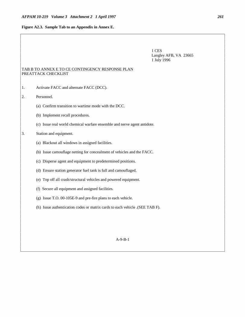
AFPAM 10-219 Volume 3 Attachment 2 1 April 1997 261
Figure A2.3. Sample Tab to an Appendix in Annex E.
1 CESLangley AFB, VA 236651 July 1996
TAB B TO ANNEX E TO CE CONTINGENCY RESPONSE PLANPREATTACK CHECKLIST
1. Activate FACC and alternate FACC (DCC).
2. Personnel.
(a) Confirm transition to wartime mode with the DCC.
(b) Implement recall procedures.
(c) Issue real world chemical warfare ensemble and nerve agent antidote.
3. Station and equipment.
(a) Blackout all windows in assigned facilities.
(b) Issue camouflage netting for concealment of vehicles and the FACC.
(c) Disperse agent and equipment to predetermined positions.
(d) Ensure station generator fuel tank is full and camouflaged.
(e) Top off all crash/structural vehicles and powered equipment.
(f) Secure all equipment and assigned facilities.
(g) Issue T.O. 00-105E-9 and pre-fire plans to each vehicle.
(h) Issue authentication codes or matrix cards to each vehicle .(SEE TAB F).
A-9-B-1
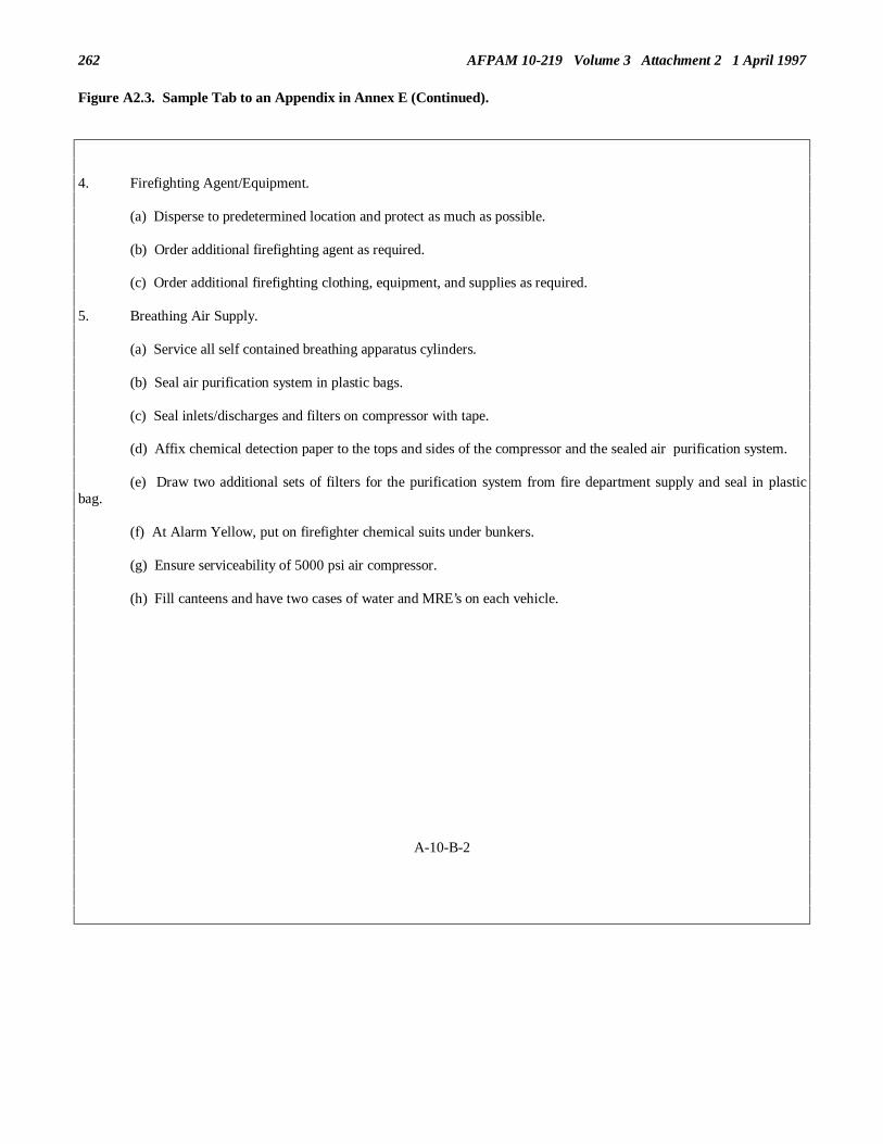
262 AFPAM 10-219 Volume 3 Attachment 2 1 April 1997
Figure A2.3. Sample Tab to an Appendix in Annex E (Continued).
4. Firefighting Agent/Equipment.
(a) Disperse to predetermined location and protect as much as possible.
(b) Order additional firefighting agent as required.
(c) Order additional firefighting clothing, equipment, and supplies as required.
5. Breathing Air Supply.
(a) Service all self contained breathing apparatus cylinders.
(b) Seal air purification system in plastic bags.
(c) Seal inlets/discharges and filters on compressor with tape.
(d) Affix chemical detection paper to the tops and sides of the compressor and the sealed air purification system.
(e) Draw two additional sets of filters for the purification system from fire department supply and seal in plasticbag.
(f) At Alarm Yellow, put on firefighter chemical suits under bunkers.
(g) Ensure serviceability of 5000 psi air compressor.
(h) Fill canteens and have two cases of water and MRE’s on each vehicle.
A-10-B-2

AFPAM 10-219 Volume 3 Attachment 2 1 April 1997 263
Figure A2.4. Sample Tab to an Appendix in Annex E.
1 CESLangley AFB, VA 236651 July 1996
TAB C TO ANNEX E TO CE CONTINGENCY RESPONSE PLANFIRE ALARM COMMUNICATION CENTER (FACC)--ACTIVATION CHECKLIST
1. GENERAL: The Fire Alarm Communication Center (FACC) will serve as the command and control center for thedeployed department.
2. EXECUTION: The FACC will implement the activation checklist in the preattack phase of the alert/exercise.
3. PROCEDURES:
a. Check Radio Communications.
(1) Base station mobile.
(2) Remote station.
(3) Portables.
(4) All spare portable radio batteries charged.
b. Check Direct Lines (numbers to be established upon deployment/FACC activation).
(1) Survival Recovery Center (SRC).
(2) Damage Control Center (DCC).
(3) Close Defense Area Headquarters (CDAH).
(4) Emergency Care Facility (ECF).
A-11-C-1

264 AFPAM 10-219 Volume 3 Attachment 2 1 April 1997
Figure A2.4. Sample Tab to an Appendix in Annex E (Continued).
c. Check Fire/Crash Reporting Phones List.
d. Keep Status Boards Up-To-Date.
(1) Vehicles.
(2) Firefighting agents.
(3) Alarm systems in shelter area.
(4) Emergency Water Sources (EWS)/Hydrant systems.
(5) On-duty firefighters.
(6) Update Fire Chief’s status board.
e. Establish Chemical Code/Duress Words.
(1) Status of Crew.
(2) Duress Codes.
(3) Chemical Code.
f. Recall Off Duty Firefighters, if needed.
g. Maps.
(1) On base grid maps.
(2) Utility maps.
(3) Water distribution system/EWS locations.
(4) Munitions/explosives area maps.
(5) POL storage and distribution locations.
h. Base Priority Facility Listing.
A-12-C-2

AFPAM 10-219 Volume 3 Attachment 2 1 April 1997 265
Figure A2.4. Sample Tab to an Appendix in Annex E (Continued).
i. Dispersal Locations.
(1) Off-duty personnel.
(2) Firefighting agents.
(3) Equipment.
j. Administrative Supplies.
(1) Paper.
(2) Pen/pencils, grease pencils.
(3) Log books/annotate date/time of FACC activation.
(4) Telephone book.
k. Reference Material.
(1) T.O. 00105E-9 (Rescue).
(2) T.O. 11A-1-46.
(3) Wartime Contingency Plan.
(4) Pre-Fire Plans.
(5) Operation Plans.
l. Alternate Firefighting Communication Center will be established by the SFO and will be used for commandand control of firefighting operations if the primary fire station (FACC) is put of commission.
A-13-C-3

266 AFPAM 10-219 Volume 3 Attachment 2 1 April 1997
Figure A2.5. Sample Tab to an Appendix in Annex E.
1 CESLangley AFB, VA 236651 July 1996
TAB D TO ANNEX E TO CE CONTINGENCY RESPONSE PLANVEHICLE DISPERSAL LOCATIONS AND AGENT/CHECKLIST
Vehicle Dispersal Point Location Vehicle Type
Bldg 745 P-10
Fire Station P-13
Quick Turn Area P-19
Bldg 94 P-12
West End Taxiway 4 P-23
Bldg 1245 P-4
Bldg 1142 P-22
Tank Farm 5 4x4
EWS #4 P-18
EWS #1 P-8
Note: Once vehicles reach their dispersal points a crew status check is to be accomplished. When status of crews is reported,the FACC will update the DCC on the above information.
A-14-D-1

AFPAM 10-219 Volume 3 Attachment 2 1 April 1997 267
Figure A2.5. Sample Tab to an Appendix in Annex E (Continued).
Equipment/Agent Dispersal Location
Extinguishers Bldg 94
Hoselines Bldg 1142
Fire/Maint Parts Bldg 1245
AFFF EWS #4
Dry Chemical Bldg 1142
Bunker Gear Bldg 505

268 AFPAM 10-219 Volume 3 Attachment 2 1 April 1997
Figure A2.6. Sample Tab to an Appendix in Annex E.
1 CESLangley AFB, VA 236651 July 1996
TAB E TO ANNEX E TO CE CONTINGENCY RESPONSE PLANEMERGENCY WATER SOURCES
EWS Location Size in Gallons
Bldg 19 50,000
Bldg 1712 40,000
Bldg 917 100,000
Lake Fred 700,000
Bldg 75 50,000
A-16-E-1

AFPAM 10-219 Volume 3 Attachment 2 1 April 1997 269
Figure A2.7. Sample Tab to an Appendix in Annex E.
1 CESLangley AFB, VA 236651 July 1996
TAB F TO ANNEX E TO CE CONTINGENCY RESPONSE PLANSAMPLE AUTHENTICATION MATRIX
A B C D E F G H I J K L M
1 11 17 24 48 16 20 30 08 15 26 33 29 26 2 50 14 09 27 32 45 19 05 18 22 34 23 07 3 47 21 38 49 16 25 36 04 03 12 17 05 43 4 27 16 32 06 24 15 33 18 14 42 18 29 22 5 30 08 33 18 34 17 27 05 02 50 29 43 19 6 44 14 12 23 43 18 46 29 36 21 29 38 13
ETC.....
Reverse side will have sequential lettering O-Z, and Random numbering as above. Sides will be labeled alpha/bravorespectively . When an order or response is given the receiving crew will verify it by calling out "alpha" or "bravo" followedby a phonetic alphabet and a number. Orders will be authenticated by cross referencing and returning the correct code to thecrew, who will then proceed as directed. Note: Matrix should be new and generated prior to deployment on a PC.
A-17-F-1
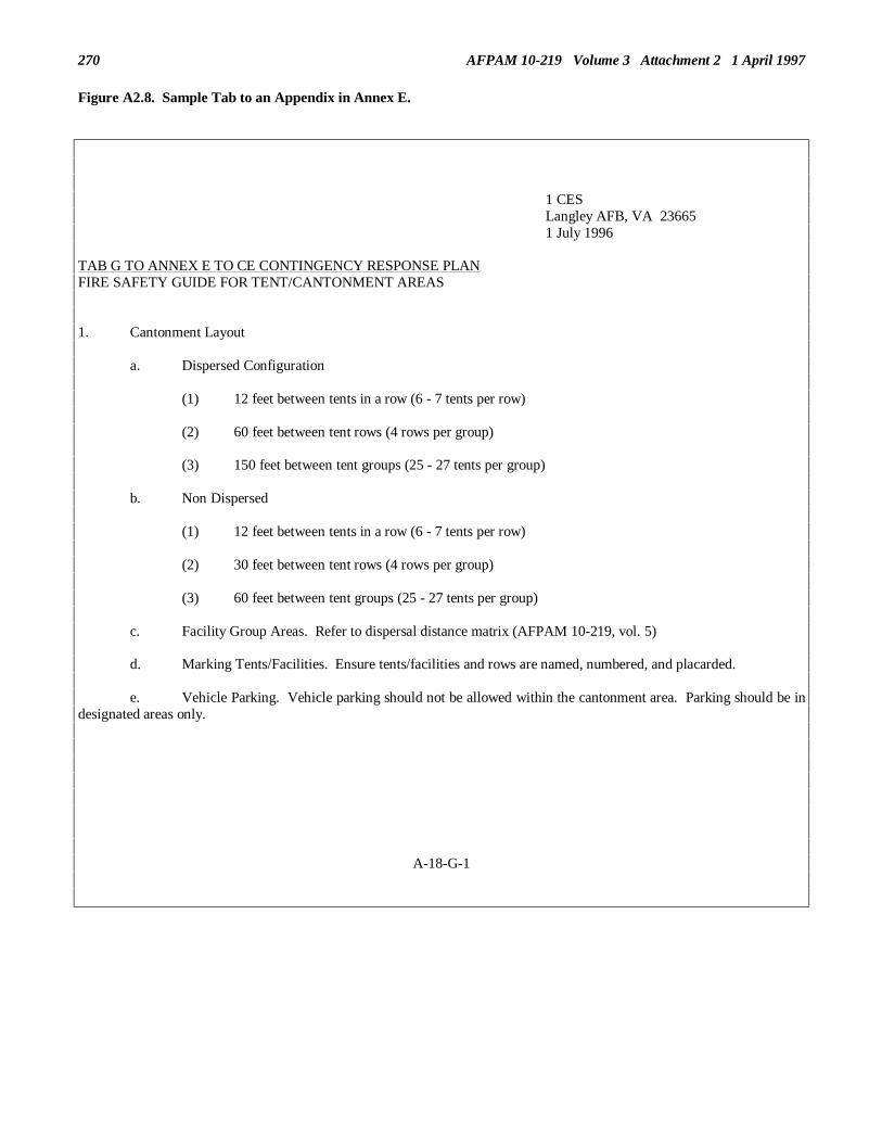
270 AFPAM 10-219 Volume 3 Attachment 2 1 April 1997
Figure A2.8. Sample Tab to an Appendix in Annex E.
1 CESLangley AFB, VA 236651 July 1996
TAB G TO ANNEX E TO CE CONTINGENCY RESPONSE PLANFIRE SAFETY GUIDE FOR TENT/CANTONMENT AREAS
1. Cantonment Layout
a. Dispersed Configuration
(1) 12 feet between tents in a row (6 - 7 tents per row)
(2) 60 feet between tent rows (4 rows per group)
(3) 150 feet between tent groups (25 - 27 tents per group)
b. Non Dispersed
(1) 12 feet between tents in a row (6 - 7 tents per row)
(2) 30 feet between tent rows (4 rows per group)
(3) 60 feet between tent groups (25 - 27 tents per group)
c. Facility Group Areas. Refer to dispersal distance matrix (AFPAM 10-219, vol. 5)
d. Marking Tents/Facilities. Ensure tents/facilities and rows are named, numbered, and placarded.
e. Vehicle Parking. Vehicle parking should not be allowed within the cantonment area. Parking should be indesignated areas only.
A-18-G-1

AFPAM 10-219 Volume 3 Attachment 2 1 April 1997 271
Figure A2.8. Sample Tab to an Appendix in Annex E (Continued).
f. Separation Distances
(1) Refer to Recommended distances between functional and individual facilities (AFPAM 10-219, vol 5)
2. Cantonment Fire Inspections
a. Conduct Frequent Inspections
b. Include Key Supervisors
c. Include Ground Safety Personnel
3. General Inspection Items
a. Electrical wiring, serviceability and installation
b. Check for homemade extension cords or lighting
c. Ensure only 60 watt or less light bulbs are used in tent lighting to prevent pyrolysis of tent material andpossible fire.
d. Ensure air conditioning/heating units, generators, and similar equipment are positioned as far from tents aspossible.
e. Electrical equipment is properly grounded.
f. Proper aisle space inside tents.
g. Ensure two means of exit are maintained in all tent facilities. Travel distance from any point in a structureto at least one exit shall not exceed 150 feet.
h. Develop and post a written evacuation plan for cantonment occupants. Include assembly points, head countprocedures, and emergency firefighting and notification procedures.
i. Enforce "No Smoking" policy inside all tents.
j. Ensure a proper and fully operational fire extinguisher is provided in each tent and hazardous operationarea. Minimum rating, 2A:10 B, C.
A-19-G-2

272 AFPAM 10-219 Volume 3 Attachment 2 1 April 1997
Figure A2.8. Sample Tab to an Appendix in Annex E (Continued).
k. Ensure tent trash receptacles are emptied daily.
l. Identify/eliminate self help projects that create life safety/fire protection hazards.
m. Ensure vegetation and trash around the cantonment area are controlled.
n. During cold weather operations when oil/gas fired heaters are used, ensure heaters are properly serviced,fuel lines are not leaking, and combustibles kept at a safe distance.
o. Recommend battery operated smoke detectors for each tent/facility used as sleeping areas. Detector shouldbe mounted on center beam of tent.
p. Open burning (i.e., bonfires, grills, etc.) within the cantonment area are discouraged.
q. Open burning of waste receptacles (latrines) should be monitored.
4. Special Hazards Areas Unique to Bare Base Operations
a. Field Kitchens
(1) Burner refueling areas must be located 50 feet from tents/facilities and lighting/generatorequipment. Ensure a fire extinguisher is readily available.
(2) Watch for the accumulation of grease on tent surfaces.
(3) Ensure disposal areas for grease are at least 8 feet from the tent.
(4) Ensure as a minimum, 2 fire extinguishers with a rating of 2A: 40 BC are provided for cookingareas. Extinguishers should be located at the entrances to the cooking areas.
(5) Ensure electrical distribution panel is located at least 6 feet from the kitchen tent and is of theprotected connector type.
(6) Ensure electrical generators are positioned at least 15 feet from tent walls. Fuel tanks should bepositioned as remote as possible from generators and diked with fuel lines protected.
(7) Portable hot water heaters must be set at least 20 feet from the dispensing area.
(8) Ensure "No Smoking" is enforced inside the tent.
(9) Ensure adequate aisles and exits are maintained.
A-20-G-3

AFPAM 10-219 Volume 3 Attachment 2 1 April 1997 273
Figure A2.8. Sample Tab to an Appendix in Annex E (Continued).
b. Generators
(1) Ensure fuel bladders are located as far as practical from other facilities.
(2) Fuel bladders require earth berms to contain any spillage/leak. Earthen berms should be capableof containing 125% of tank capacity.
(3) Ensure all generators are properly grounded.
(4) Ensure an extinguisher with a minimum rating of 2A:10 B, C is available in the area.
(5) Ensure "No Smoking" signs are posted around fuel storage areas.
(6) Ensure vegetation control in generator and fuel storage areas is implemented.
c. Medical Facilities. In addition to general inspection areas, ensure there is a minimum of one 150 lb halonflightline fire extinguisher available for air evacuation/helipad operations.
A-21-G-4

274 AFPAM 10-219 Volume 3 Attachment 2 1 April 1997
Figure A2.9. Sample Tab to an Appendix in Annex E.
1 CESLangley AFB, VA 236651 July 1996
TAB H TO ANNEX E TO CE CONTINGENCY RESPONSE PLANFIRE SAFETY GUIDE FOR MUNITION STORAGE AREAS
1. General Layout
a. Distances from other facilities outlined in AFPAM 10-219 and AFR 127-100.
b. Minimum separation distances based upon storage.
2. General Storage Requirements
a. Open Storage
(1) Without any type of barricades, munition storage should be temporary only.
(2) Ensure separation distances between stacks are maintained. (Refer to minimum distanceseparation guide AFPAM 10-219)
b. Covered Storage
(1) Normally accomplished by using igloo ammunition storage facilities or combat zone type steelarch or culvert igloos/covered igloos.
(2) Net Explosive Weight (NEW) in nonstandard earth covered igloos is 250,000 pounds. Quantity-Distance criteria is outlined in AFPAM 10-219.
3. Fire Prevention Practices
a. Ensure flame and spark producing devices are kept out of the area.
b. Maintain proper separation distances and vegetation control.
A-22-H-1

AFPAM 10-219 Volume 3 Attachment 2 1 April 1997 275
Figure A2.9. Sample Tab to an Appendix in Annex E (Continued).
c. Ensure refuse and packing material are not allowed to accumulate.
d. Ensure fire breaks are provided around each storage area.
e. Intentional/controlled burning will not be permitted within 200 feet.
f. Flammable liquids for cleaning will not be permitted.
g. Flammable storage will be located at least 50 feet from explosive storage locations.
h. Vehicles other than those loading or unloading will not be parked closer than 25 feet to any storage facility.
A-23-H-2

276 AFPAM 10-219 Volume 3 Attachment 2 1 April 1997
Figure A2.10. Sample Tab to an Appendix in Annex E.
1 CESLangley AFB, VA 236651 July 1996
TAB I TO ANNEX E TO CE CONTINGENCY RESPONSE PLANFIRE SAFETY GUIDE FOR FUEL STORAGE AREAS
1. Expedient Operating Storage (50,000 gal bladders). Fire Prevention Practices.
a. Ensure dispersal distance from facility group areas is maintained in accordance with AFPAM 10-219.
b. Ensure the bulk fuel storage area is situated so that any rupture of a bladder or destruction of dike will notallow fuel to flow into adjacent cantonment areas.
c. Ensure fuel bladder is surrounded by earthen berm to contain 125% of tank capacity in case of rupture.
d. Ensure fuel dispensing equipment is properly grounded.
e. Ensure vegetation control is properly maintained.
f. Implement "No Smoking" policy in and around fuel storage and dispensing area.
g. As a minimum, one fire extinguisher with a rating of 2A:60 B,C will be located in each fuel storage area.
h. Ensure all fuel drums are properly bonded and grounded.
i. Limit vehicles in the area to those required to accomplish tasks.
j. Vehicles will not be parked within 50 feet of the POL area.
A-24-I-1

AFPAM 10-219 Volume 3 Attachment 2 1 April 1997 277
Figure A2.11. Sample Tab to an Appendix in Annex E.
1 CESLangley AFB, VA 236651 July 1996
TAB J TO ANNEX E TO CE CONTINGENCY RESPONSE PLANGUIDE FOR FIRE PROTECTION STANDBY REQUIREMENTS
1. Integrated Combat Turn (ICT). Simultaneous refueling, munitions loading/unloading, external fuel tankloading/unloading with all engines shutdown.
a. Requires one 150 lb halon flightline extinguisher to be located in the fuel service safety zone.
b. Requires a CFR vehicle standby. It should be positioned for optimum response.
2. Hot Refueling/Multiple Hot Refueling. The transfer of fuel into fuel tanks of an aircraft with one or more engineson the aircraft operating with or without munitions on board.
a. Requires one 150 lb halon flightline extinguisher to be located between the refueling equipment and therefueling supervisor.
b. Requires a CFR vehicle standby. It should be positioned for optimum response.
3. Hot Integrated Combat Turn. Simultaneous refueling, munitions loading/unloading, external fuel tankloading/unloading with engines operating.
a. Requires one 150 lb halon flightline extinguisher to be located in the fuel service safety zone.
b. Requires a CFR vehicle standby. It should be positioned for optimum response.
4. Abnormal Defuel. Defueling an aircraft that has a fuel leak, is damaged from a fire or impact, defueling into opencontainers or drums, defueling where safe distance criteria cannot be met, or static grounding points are not available.
a. Requires one 150 lb halon flightline extinguisher for each aircraft.
b. Requires a CFR vehicle standby. It should be positioned just outside the fuel servicing safety zone.
A-25-J-1

278 AFPAM 10-219 Volume 3 Attachment 2 1 April 1997
Figure A2.11. Sample Tab to an Appendix in Annex E (Continued).
5. Aircraft Servicing Inside a Hardened Aircraft Shelter (HAS)
a. Integrated Combat Turn in a HAS
(1) Requires one 150 lb halon flightline extinguisher for each aircraft shelter.
(2) Requires a CFR vehicle standby. It should be positioned within the aircraft shelter area.
b. Hot Integrated Combat Turn and Hot Refueling in a HAS.
(1) Requires two 150 lb halon flightline extinguisher for each aircraft shelter.
(2) Requires a CFR vehicle standby. It should be positioned just outside the fuel servicing safety zone. TheHAS aircraft entry door(s) must remain fully open.
6. Medical Evacuation Flights. Loading and Unloading of Medical Patients.
a. Requires one 150 lb halon flightline extinguisher for each aircraft.
b. During contingency operations, safety dictates a CFR vehicle standby regardless of the type of fuel on theaircraft. It should be positioned for optimum response.
A-26-J-2

AFPAM 10-219 Volume 3 Attachment 3 1 April 1997 279
SUBJECT INDEX-A-
Abbreviations, attachment 1Air Base Defense, 12.4.5Air Force Repair Responsibilities, 7.3.5, 11.3.2.2Aircraft Arresting Systems, 7.6.1Airfield Fire Suppression, 10.5.4Airfield Lighting Systems, 7.6.2Alpha Particles, 3.4.2.1, 3.4.3.3Alternate Command Posts, 2.9.5, 3.8.3.2.3, 3.8.3.2.4Antiterrorism, 12.5Army Repair Responsibilities, 7.3.6, 11.3.2.1Artesian Well, 7.8.1.2Automatic Liquid Agent Detection System, 3.6.3.1.5Auxiliary Firefighting, 10.6
-B-
BAK-12 Aircraft Arresting System, 8.4.1Base Defense Operations Center, 2.9.2Base Denial, 13.3
Methods, 13.4Responsibilities, 13.5
Base Recovery After AttackInitial Activities, 2.13Organization, 2.9
Beta Particles, 3.4.2.2, 3.4.3.3Biological Monitoring, 3.6.5Blister Agents, 5.3.1.2Blood Agents, 5.3.1.3Bomb Removal Teams, 3.8.3.2.13Bracing, 7.9.3.2
-C-
Camouflage, 12.4.1.1.3Camouflets, 4.4.8.5Chain of Command, 2.9Chemical Agents, 5.3Chemical Defense Ground Crew Ensemble, 5.4
Limiting Factors, 5.4.1Readiness Postures, 5.4.2
Chemical Monitoring, 3.6Environment, 3.6.2.1Equipment, 3.6.3Procedures, 3.6.4
Choking Agents, 5.3.1.4Code Systems, 12.4.1.6Collective Protection, 5.5Command and Control
Concepts, 2.3Continuity, 2.15Knowledge, 2.7Relationships, 2.3.3, 2.5
Communications, 2.14, 10.5.7, 12.4.1.7.1Concealment, 12.4.1.1.2Convoy Operations, 12.4.2
Command and Control, 12.4.2.4Defensive Measures, 12.4.2.8

280 AFPAM 10-219 Volume 3 Attachment 3 1 April 1997Organization, 12.4.2.1Planning, 12.4.2.6
Cover, 12.4.1.1, 12.4.1.1.1.Craters, 4.4.8.4
-D-
Damage Assessment, 2.13.4, 6.3Priorities, 6.9.2Reports, 6.9.3, 6.9.4
Damage Assessment and Response Team, 3.8.3.2.5, 4.6.4Assessment Techniques, 6.6, 6.7, 6.8Composition, 3.8.3.2.5, 6.4.1Equipment, 6.5Reports, 6.9.3
Damage Control CenterEquipage, 2.11.1Manning, 2.9.3, 2.11, 3.8.3.2.2Responsibilities, 2.9.3, 2.11, 6.3, 6.8
Debris Clearance, 2.13.2, 7.10Decontamination
Area, 5.8Equipment, 5.6Personnel, 5.7Vehicle, 5.9
Disaster Response Force, 2.9Dispersal, 3.3
-E-
Electrical Repairs, 7.7.2Distribution System, 7.7.2.2Interior Wiring, 7.7.2.3Production System, 7.7.2.1
Emergency Airfield Lighting System. 9.2, 9.5.3Emergency Airfield Lighting System Teams. 3.8.3.2.14Emergency Teams, 3.8Expedient Structural Repairs, 7.9Evacuation, 13.6Expedient Wells, 7.8.3Explosive Ordnance Disarmament and Removal, 4.5
Equipment, 4.5.3Removal, 4.5.2Safing, 4.5.1
Explosive Ordnance Disposal Teams, 3.8.3.2.12Explosive Ordnance Reconnaissance, 4.4
Equipage, 4.4.6Marking, 4.4.5.2.Procedures, 4.4.7Reporting, 4.4.9Safety, 4.4.4
Extinguishing Agents, 10.4.2
-F-
Fallout Protection, 3.4.3Fighting Position Construction, 12.4.1.5Fire Department, 3.8.3.2.10, 10.3.1Fire Marshal, 10.3.2Fire Protection Manning, 10.4.1

281 AFPAM 10-219 Volume 3 Attachment 3 1 April 1997Fire Protection Operations, 10.5, attachment 2
-G-
Gamma Rays, 3.4.2.3, 3.4.3.1.1, 3.4.3.3Generator Response Team, 3.8.3.2.14Gravity Well, 7.8.1.1Guying, 7.9.3.1
-H-
Harvest Eagle Lighting Set, 9.2, 9.5.1Heating Systems Repair, 7.7.8
Alternative Heating Sources, 7.711Central Heating Systems, 7.7.9Individual Heating Systems, 7.7.10
-I-
Initial Response Force, 3.5.2
-J-
Jacking, 7.9.3.3
-K-
KM Anchor System, 8.3.4.2, 8.3.5.2
-M-
M8 Paper, 3.6.3.1.1M8A1 Alarm System, 3.6.3.1.4M9 Paper, 3.6.3.1.2M60 Mass Ordnance Clearance Vehicle, 4.5.4M90 Vapor Agent Detector, 3.6.3.1.6M256 Kit, 3.6.3.1.3Mass Ordnance Clearance, 4.6Mobile Aircraft Arresting System, 8.3
Anchoring, 8.3.4Characteristics, 8.3.1Installation, 8.3.2, 8.3.3
Mobile Aircraft Arresting System Installation Team, 3.8.3.2.16Moil Points, 8.3.4.4, 8.3.5.3Movement Techniques, 12.4.1.2.
File Formation, 12.4.1.High Crawl, 12.4.1.3.2Low Crawl, 12.4.1.3.1Rush, 12.4.1.3.3Spider Crawl, 12.4.1.3.4.Wedge Formation, 12.4.1.4
-N-
Natural Gas System Repair, 7.7.5, 7.7.6, 7.7.7Navigation Aids, 7.6.3Nerve Agents, 5.3.1.1Nonpersistent Agents, 5.3.4.2Nuclear Accident Response, 3.5Nuclear, Biological and Chemical Cell

282 AFPAM 10-219 Volume 3 Attachment 3 1 April 1997Manning, 2.9.2Responsibilities, 2.9.2
Nuclear, Biological, and Chemical Reconnaissance Teams, 3.8.3.2.11
-O-
Operations and Maintenance, 11.3.3Aircraft Arresting Systems, 11.4.1Airfield Lighting Systems, 11.4.2Electrical System, 11.5.1Facilities, 11.6.1Heating Systems, 11.5.4POL Systems, 11.5.6Sewage System, 11.5.3.1Water System, 11.5.2
OPREP-3 Report, 6.9.4.1Owner/User Security, 12.4.5.5
-P-
Persistent Agents, 5.3.4.1Personnel Accountability, 3.7POL Rapid Utility Repair Kits, 7.7.18POL System Repairs, 7.7.17.Portable Lighting, 7.11
-R-
Radiological Monitoring, 3.4Rapid Runway Repair Damage Assessment Team, 3.8.3.2.6Rapid Runway Repair Lighting Set, 9.2, 9.5.2Rapid Runway Repair Team, 3.8.3.2.7Roof Repairs, 7.9.4.1
-S-
Search and Rescue, 2.13.2, 10.7Communications, 10.7.3.1Off-Base, 10.7.4.2On-Base, 10.7.4.1
Sewer System Repair, 7.7.14Lift Stations, 7.7.14.2Lines, 7.7.14.1Treatment Plants, 7.7.14.3
SITREP Report, 6.9.4.3Splinting, 7.9.3.4Stitching Dogs, 7.9.3.6Stockpiling, 11.8Structural Fire Suppression, 10.5.5Structural Repair Team, 3.8.3.2.8Structural Repairs, 7.9.3
Bracing, 7.9.3.2Guying, 7.9.3.1Jacking, 7.9.3.3Splinting, 7.9.3.4Stitching Dogs, 7.9.3.6Tension Ties, 7.9.3.5Welding, 7.9.3.7
Survival Recovery Center, 2.10Engineer Tasks, 2.10.2

283 AFPAM 10-219 Volume 3 Attachment 3 1 April 1997Equipage, 2.10.1Manning, 2.9.2, 3.8.3.2.1Responsibilities, 2.9.2. 6.3
-T-
Tempest Rapid Report, 6.9.4.2Tension Ties, 7.9.3.5Threats, 12.3-U-
Utilities Repair Teams, 3.8.3.2.9
-V-
Vehicle hardening, 12.4.1.9
-W-
Wall Repairs, 7.9.4.2Water System Repairs, 7.7.4
Distribution System, 7.7.4.4Source, 7.7.4.1.Storage Facilities, 7.7.4.3Treatment Facilities, 7.7.4.2
Welding, 7.9.3.7Well Development, 7.8..3.5Wells, 7.8.3
Bored Wells, 7.8.3.3Driven Wells, 7.8.3.2Dug Wells, 7.8.3.1Jetted Wells, 7.8.3.4
Window Repair, 7.9.4.3Wing Operations Center, 2.9.1Withdrawal, 13.6Work Party Security, 12.4.4
-X-
X-rays, 3.4.2.3, 3.4.3.1.1