Embed Size (px)
Citation preview

TENSIONINGPOST
CONSTRUCTION, ENGINEERING & GEOTECHNICAL
SPECIALISTS

2

TABLE OF CONTENTS
MK4 SYSTEMIntroduction 2Quality 2
STRAND PROPERTIESStrand Properties 3
FLAT SLAB SYSTEMFlat Slab Live End Anchorage FMA505 4Flat Slab Live End Anchorage FMA506 4Flat Slab Dead End Anchorage FSO505/506 5Flat Slab Swaged End Anchorage FSS505/506 5Mono Strand Duct Systems 6Anchorage Reinforcement Requirements 6Surfacing Stressing Blockout Requirements (Pans) 7Jacking 7
MULTI-STRAND SYSTEMThe Multi-Strand System 8Multi-Strand Live End Anchorages MSA 8Multiple Coupler MCB 9Bonded Dead End Anchorage MSO 10Swaged End Anchorage MSS 10Intermediate Anchor MZE 11
MULTI-STRAND DUCT DETAILSCorrugated Steel Ducts 12HDPE and PP Ducts 12
MULTI-STRAND DETAILING REQUIREMENTSMulti-Strand Stressing Minimum Edge Distance/Bursting Reinforcement 13
MULTI-STRAND BLOCKOUT DIMENSIONSMulti-Strand Blockout Dimensions 14
TENDON PROPERTIESStrand 0.6” 15
CALCULATION NOTES 16-24
1

MK4 SYSTEM
Introduction
Fortec Australia Pty Ltd is a privately owned Australian company specialising in construction, engineering and geotechnical services, and is part of the Ertech Group of Companies. Our team comprises specialist engineers and contracting professionals who have worked in the industry for many years. Fortec Australia has considerable knowledge and experience in all aspects of post-tensioning works. The services we offer include the following post-tensioning systems:
• Multi-strand post-tensioning: Our MK4 post-tensioning system is used in buildings, tanks, bridges and many other structures within Australia and the world.
• Flat slab post-tensioning: Our post-tensioned slab system (Flat Slab system) is predominately used for building structures and industrial pavements.
• External post-tensioning: External PT is mostly used in strengthening existing structures or for replacement applications where previous designs do not meet updated standards.
Fortec staff has been responsible for the design and installation of post-tensioning systems throughout Australia, Europe, Asia and the Middle East. Our post-tensioning system includes a range of anchorages, accessories and the necessary equipment to respond to the technical requirements for the construction of building, bridges and other structures.
All multi-strand components have been designed and tested in accordance with the European code ETAG-013, thus we deliver world class technologies and systems to every market we service.
Our experience in various post-tensioning applications and our team of engineers and technicians are the reason for our success in delivering exceptional results for our clients. We provide post-tensioning solutions for many structures like bridges, buildings, Liquefied LNG tanks, silos and various other suspended structures.
Fortec Australia can provide the following services:
• Technical assistance in all the phases of the project; from the design to the final execution.
• Installation of post-tensioning only services where design input is not required. • Design and construct building design packages• Study of alternative design or construction method as an improvement for the
optimum solution for every project.
Quality
Fortec Australia and its parent companies utilise a complete Quality Assurance Programme conforming to ISO 9001:2000, including the design, production, supply and installation of all post-tensioning works.
2

STRAND PROPERTIES
Strand properties
The strand used for post-tensioning tendons are comprised of 7-wires low relaxation steel. The most common diameters used in Australia are 0.5” (12.7mm) and 0.6” (15.2mm).
The following table gives the main characteristics of each common size of strand manufactured and corresponding code manufactured to.
Strand Type Standard Strand Size Fpk Nominal ø Cross Section Weight Min. BreakingLoad Fpk
Relaxation 1000h
at 70% of Fpk
% Proof Force
mm Mpa mm mm2 kg/m kN % kN
12.7mm(0.5”)
AS 4672 12.7 1870 MPa 12.7 98.6 0.774 184 2.50% 156*
BS 5896:1980 12.9 1860 MPa 12.9 100 0.785 186 2.50% 158*
prEN 10138-3 12.9 1860 MPa 12.9 100 0.781 186 2.50% 164*
15.2mm and 15.7mm
(0.6”)
AS 4672 15.2 1830 MPa 15.2 143 1.122 261 2.50% 222*
BS 5896:1980 15.7 1770 MPa 15.7 150 1.180 265 2.50% 225*
prEN 10138-3 15.7 1860 MPa 15.7 150 1.172 279 2.50% 246*
Note: * AS4672 Proof Force = 0.2%, BS 5896, prEN10138 Proof Force = 0.1%Notes: Modulus of Elasticity for 7 Wire Strand ranges between 180 - 205GPa
3

FLAT SLAB SYSTEM
Flat Slab Live End Anchorage FMA505
Fortec FMA505 anchorages for slab post-tensioning in buildings, bridge decks and other applications consist of up to 5 No. strands of 12.7mm (0.5”) or 4No. strands of 15.2mm (0.6”) diameter placed inside a 70mm flat duct. The strands are tensioned and locked off individually using a mono-strand jack.
Flat Slab Live End Anchorage FMA506
The FMA506 system is similar to the FMA505 system but has additional capacity to accommodate 5 No.15.2mm diameter strands. The system uses the larger 90mm x 19mm flat duct system.
Strand Size Tendon Type
No Strands
Anchorage Casting Dimension (mm)
Recess Former Size (mm) Flat Duct Size
Minimum Concrete Thickness
Minimum Vertical Anchor Spacing
Minimum Edge
Distance/Anchor Spacing
mm A B C D E F G H mm mm mm mm
12.7mm (0.5”)
305 3 215 220 79 100 265 315 80 100 70 x 19 140 100 300
405 4 215 220 79 100 265 315 80 100 70 x 19 150 100 300
505 5 215 220 79 100 265 315 80 100 70 x 19 160 100 300
15.2mm(0.6”)
306 3 215 220 79 100 265 315 80 100 70 x 19 150 100 300
406 4 215 220 79 100 265 315 80 100 70 x 19 160 100 300
506 5 270 265 79 100 265 315 80 100 90 x 19 170 100 300
Flat Slab Coupling Anchorage FSC505/506
When there is a requirement for continuity of the tendon through a construction joint couplers are a solution that engineers can utilise to ensure the tendon force is continuous throughout the entire length of the tendon. Couplers are mostly used on industrial pavements where a reduction of movement joints is preferred or where load continuity is critical.
Strand Size Tendon Type
No Strands FSC Coupling Anchorage (mm)
Minimum Concrete Thickness
Minimum Edge Distance/Anchor
Spacing
mm A B C D mm mm
12.7mm (0.5”)
405 2, 3 or 4 100 220 80 220 170 300
505 5 100 220 110 220 200 300
15.2mm(0.6”)
406 2, 3 or 4 100 220 110 220 220 300
506 5 100 250 120 270 220 300
C
BD
A
B
AC
4

FLAT SLAB SYSTEM
Flat Slab Swaged End Anchorage FSS505/506
An alternative dead end option for the flat slab system is a Swaged Dead End. The anchorage consists of a swaged strand manufactured on site, bearing against a 12mm thick steel plate. The swage can consist of a compressed barrel/wedge or conventional swage. This exposed strand is greased to ensure load transfer to the swage plate. This anchorage is typically used in beams to ensure force is transferred to the back of the column. The anchorage lengths and dimensions of the dead end plate are indicated in the table below.
Strand Size Tendon Type
No Strands
FSO Onion Dead End (mm)
FSS Swaged Dead End (mm)
Minimum Concrete Thickness
Minimum Vertical Anchor Spacing
Minimum Edge
Distance/Anchor Spacing
A B L A B L mm mm mm
12.7mm (0.5”)
305 2 or 3 50 230 1050 75 500 200 140 100 300
405 4 50 270 1050 75 500 250 150 100 300
505 5 50 350 1050 75 600 300 160 100 300
15.2mm(0.6”)
306 2 or 3 50 230 1350 75 500 225 150 100 300
406 4 50 270 1350 75 600 300 160 100 300
506 5 50 350 1350 75 600 350 170 100 300
Flat Slab Dead End Anchorage FSO505/506
For the dead ends of a flat anchorage we utilise the anchorage type FSO which is easy to execute and cost effective. The anchorage consists of ‘onion end’ bulbs manufactured on site with our specialist equipment. The anchorage lengths and dimensions are indicated in the table below.
L
B
A
B L
A
5

FLAT SLAB SYSTEM
Mono Strand Duct Systems
Post-tensioned tendons are encapsulated within concrete in a duct which is usually manufactured in galvanised steel with a wall thickness between 0.3 mm and 0.5 mm. The ducts are normally supplied in 5-6m lengths and are joined on site via a manufactured bell-end. Once stressing has been completed and approved by the design engineer the ducts are filled with cementitious grout to ensure the tendon achieves adequate bond and corrosion protection throughout the life of the structure. The flat slab system has two common sizes being 70mm and 90mm ducting. (Note - 43mm ducting is available for use with 3 strand systems but not commonly used).
Strand Size Tendon Type
No Strands
Flat Duct Size
FSO Onion Dead End (mm)
FSS Swaged Dead End (mm)
Strand Offsets and Eccentricity (mm)
mm A B L A B L A B E
12.7mm (0.5”)
505 2 or 3 70x19 50 230 1050 75 200 500 7 12 2.5mm
505 4 70x19 50 270 1050 75 250 500 7 12 2.5mm
505 5 70x19 50 350 1050 75 300 600 7 12 2.5mm
15.2mm(0.6”)
406 2 or 3 70x19 50 230 1350 75 225 500 8 12 1.5mm
406 4 70x19 50 270 1350 75 300 600 8 12 1.5mm
506 5 90x19 50 350 1350 75 350 600 8 12 1.5mm
Anchorage Reinforcement Requirements
The flat slab system requires anti-burst reinforcement to ensure the forces generated during stressing are confined. There are numerous types of anti-burst solutions but the common anti-burst reinforcement is the spiral. This allows the anti-burst to be installed over the anchorage with minimum disruption and improves the installation process, thus is the most commonly used option.
Strand Size Tendon Type
No Strands
Helical Cage (Spiral) Anti-Burst (mm)
Bar Type Transfer Strength
X Y N PITCH (mm) MPa
12.7mm (0.5”)
405 2, 3 or 4 100 260 5 60 R10 22
505 5 100 260 5 60 R10 22
15.2mm(0.6”)
406 2 or 3 100 260 5 60 R10 22
406 4 110 300 7 60 N10 25
506 5 110 300 7 60 N10 25
Note: Anti-burst reinforcement is for the primary bursting stresses and must be supplemented with other edge reinforcement and/or additional shear ties within a beam. Along the edge of the slab it is always recommended to detail U-bars/L-bars plus longitudinal reinforcement to control tensile spalling stresses between the anchorages and to adequately reinforce the untensioned zone which occurs between anchorages.
Section at tendon low point Section at tendon high point
6

FLAT SLAB SYSTEM
Surfacing Stressing Blockout Requirements (Pans)
Surface stressing blockouts (Pans) are used in locations where edge access is not available or not preferred due to finishing requirements. It is common for stressing pans to be used in residential developments where exposed balcony edges require strict finishing requirements, and as such edge stressing is not possible. Pans are also required in areas where stressing access is not possible.
Jacking
The commonly used single strand centre hole jack is compact, lightweight and can be handled without the requirement for crane or support frames. Current mono-strand jacks are designed to be able to stress both common strand sizes. The nose and internal wedges can be modified with ease to allow stressing of both strand sizes. The jacks used require certain minimum clearance requirements to allow the effective stressing. The table below details these minimum jacking clearance requirements.
Strand Size Tendon Type No Strands Minimum Clearance Requirement Dimensions (mm)
mm A B C D E
12.7mm (0.5”)
405 2, 3 or 4 500 800 750 450 70
505 5 500 800 750 450 70
15.2mm(0.6”)
406 2, 3 or 4 500 800 750 450 70
506 5 600 800 850 450 70
7

MULTI-STRAND SYSTEM
Strand Type Tendon Type Trumpet Type øA B C D Lø1 LR ø1 ø2 Minimum Radius of Curvature
mm mm mm mm mm mm mm mm mm
(0.6”)15.2mm
and 15.7mm
4 T-4 110 50 170 155 600 51/56 3000
5 T-4 110 50 170 155 600 51/56 3000
7 T-5 129 61 194 150 600 62/67 3000
9 T-6 144 60 220 175 900 72/77 4000
12 T-7 165 72 254 200 900 85/90 4000
15 T-8 186 78 282 235 900 90/95 4500
19 T-19 200 94 314 230 250 1.200 103/108 100/105 5000
24 TR-24 239 95 356 640 1.200 110/115 5000
27 TR-31 252 105 395 720 1.500 120/125 6000
31 TR-31 268 115 395 720 1.500 120/125 6000
37 TR-37 296 128 444 770 1.500 130/137 6500
43 TR-43 330 144 490 1.100 1.500 140/147 6500
The Multi-Strand System
Fortec Australia is the licensee of MK4 systems. Design and testing on the systems are in accordance with the new European standard ETAG-013 for post-tensioning systems. Our range of anchorages include live end, dead end, coupled and free floating anchorage systems for use on numerous civil and structural applications.
Multi-Strand Live End Anchorages MSA
Multi-Strand anchorages facilitate the introduction of a typically significant and concentrated post-tensioning force in the tendon, with the tensioning operations carried out by hydraulic jacks. Predominately used on civil structures like bridges, tanks and dam walls, and are used in Building applications where transfer beams, slabs are required.
The MSA Live End anchorages have been designed to comply with the most demanding of international standards such as ETAG, Eurocode etc.
Each basic anchorage consists of an anchor casting trumplate, anchor block and individual wedges. All the elements of the anchorages and corresponding dimensions have been carefully selected and tested to achieve the greatest economy in design. (See table below).
ØA
C
B
D
LØ1 LR
Ø1
Ø2
8
MULTI-STRAND SYSTEM
Strand Type Tendon Type Trumpet Type øB LB ø1 ø2 øP P
mm mm mm mm mm mm
(0.6”)15.2mm
and 15.7mm
Cyl
indr
ical
Coni
cal
4 T-4 140 385 62 51 134 87
5 T-4 156 463 62 51 134 87
7 T-5 188 615 72 62 180 98
9 T-6 208 664 85 72 200 97
12 T-7 252 749 95 85 244 97
15 T-8 270 784 100 90 265 102
19 T-19 274 773 110 100 265 127
24 T-24 325 1.015 120 110 315 122
27 T-31 350 1.280 130 120 341 127
31 T-31 350 1.280 130 120 341 127
37 T-37 390 1.300 135 130 375 155
43 T-43 455 1.600 150 140 445 180
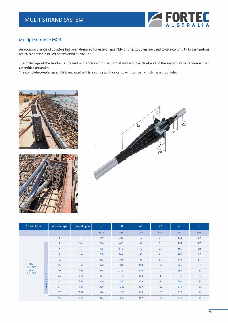
Multiple Coupler MCB
An economic range of couplers has been designed for ease of assembly on site. Couplers are used to give continuity to the tendons which cannot be installed or tensioned as one unit.
The first-stage of the tendon is stressed and anchored in the normal way and the dead end of the second-stage tendon is then assembled around it.The complete coupler assembly is enclosed within a conical/cylindrical cover (trumpet) which has a grout inlet.
9
Ø1
Ø2
ØB
ØP
P
LBB

MULTI-STRAND SYSTEM
Bonded Dead End Anchorage MSO
The anchorage MSO comprises a thin spacer plate with each consisting of a forged onion. These anchorages are embedded in the structure and so take advantage of the bond between the strand and concrete.
Strand Type Tendon Type A B C D E F G
mm mm mm mm mm mm mm
(0.6”)15.2mm
4 160 160 115 600 220 220 1250
7 240 240 115 600 340 220 1250
12 260 260 115 750 340 280 1500
19 360 300 115 900 460 340 1500
22 360 300 115 900 580 340 1500
31 450 400 115 1.050 700 400 1500
35 450 400 115 1.050 700 400 1500
43 500 400 115 1.200 700 540 1500
Swaged End Anchorage MSS
The anchorage MSS comprises of swaged strands that bear on a 15mm thick steel plate. These anchorages are embedded in the structure and so take advantage of the bond between the strand and concrete, and have the added strength of a swaged strand supported by the bearing plate.
A
B
C
D
G
E
F
10
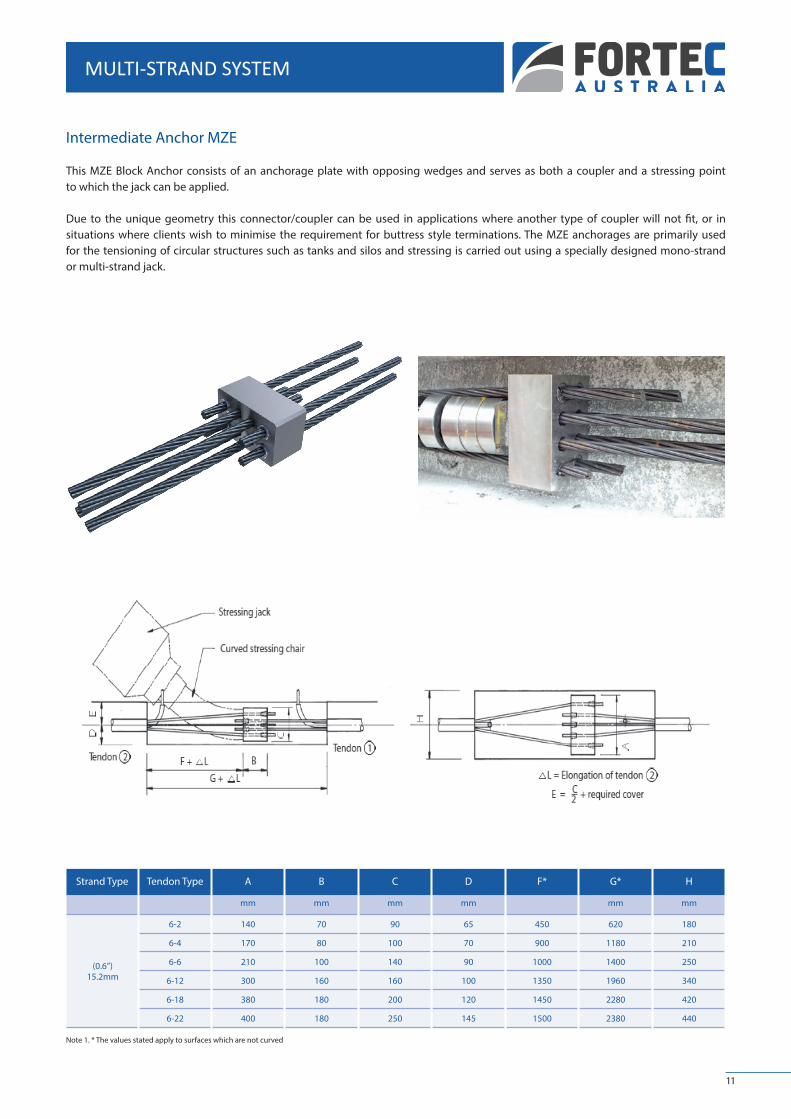
Intermediate Anchor MZE
This MZE Block Anchor consists of an anchorage plate with opposing wedges and serves as both a coupler and a stressing point to which the jack can be applied.
Due to the unique geometry this connector/coupler can be used in applications where another type of coupler will not fit, or in situations where clients wish to minimise the requirement for buttress style terminations. The MZE anchorages are primarily used for the tensioning of circular structures such as tanks and silos and stressing is carried out using a specially designed mono-strand or multi-strand jack.
Strand Type Tendon Type A B C D F* G* H
mm mm mm mm mm mm
(0.6”)15.2mm
6-2 140 70 90 65 450 620 180
6-4 170 80 100 70 900 1180 210
6-6 210 100 140 90 1000 1400 250
6-12 300 160 160 100 1350 1960 340
6-18 380 180 200 120 1450 2280 420
6-22 400 180 250 145 1500 2380 440
Note 1. * The values stated apply to surfaces which are not curved
11
MULTI-STRAND SYSTEM

MULTI-STRAND DUCT DETAILS
HDPE and PP Ducts
For enhanced corrosion protection and fatigue resistance of the tendons, the use of corrugated high strength polyethylene (HDPE) and polypropylene (PP) products is highly recommended.
The diameters available are detailed in the table below. Due to the nature of the product all HDPE and PP Ducts for post-tensioning are imported thus ensure adequate lead times are considered. Please contact our technical department for further information.
Corrugated Steel Ducts
Post-tensioned tendons are encapsulated within concrete in a duct which is usually manufactured in galvanized corrugated steel, with a wall thickness between 0.3 mm and 0.5 mm. The ducts are normally supplied in 5-6 m lengths and are coupled on site. Ducts are injected with cementitious grout after stressing to ensure the tendon achieves adequate bond and corrosion protection throughout the life of the structure.
Strand Size Tendon Type Duct Size(mm)
Corrugated Steel Min Wall
Thickness
HDPE/PP Min Wall
Thickness
Minimum Radius of Curvature
Minimum Straight Length
Minimum Loop Tendon
Radius
Strand Eccentricity
Inside ø mm
Outside ømm
(mm) (mm) (m) (m) (mm) (mm)
(0.6”)15.2mm
4 51 56 0.3 2.0 3000 400 600 5
5 51 56 0.3 2.0 3000 400 600 4
7 62 67 0.3 2.0 3000 500 700 10
9 62 67 0.3 2.0 4000 500 700 9
12 72 77 0.3 2.5 4000 600 800 12
15 85 90 0.3 3.0 4500 700 800 11
19 90 95 0.5 3.0 5000 750 900 11
24 100 105 0.5 3.0 5000 800 1100 15
27 110 115 0.5 3.5 6000 900 1200 16
31 120 125 0.5 4.0 6000 1000 1300 19
37 130 137 0.5 4.0 6500 1050 1400 19
43 140 147 0.5 4.0 6500 1150 1500 20
12

MULTI-STRAND DETAILING REQUIREMENTS
13
Multi-Strand Stressing Minimum Edge Distance/Bursting Reinforcement
The centre spacing distance CD and edge distance ED between individual anchorages are shown in the table below. These dimensions are dependent on the cover required for the structure. Note 1) details the alternative method for calculating the minimum distances required for different concrete cover specifications.
The typical bursting reinforcement is in the form of a paired stirrup cage. This reinforcement is required in the local zone to resist the bursting stresses. Additional stirrups will need to be assessed to aid the bursting spiral in reducing crack widths under various loading conditions. The local bursting reinforcement is given in the working tables below.
Ribbed reinforcing steel grade Re > 500 MPa is specified for our multi-strand post-tensioning systems.
Note that the concrete section will still require a section check for the adequacy of the reinforcement required.
Tendon Type 406 506 706 906 1206 1506 1906 2406 2706 3106 3706
Number of Strands 4 5 7 9 12 15 19 24 27 31 37
Minimum concrete strength at time of stressing, cylinder
Minimum concrete strength in Mpa
fcm, 0 25 45 25 45 25 45 25 45 25 45 25 45 25 45 25 45 25 45 25 45 25 45
Anchorage centre spacing and minimum edge distance
Centre spacing CD 245 185 270 205 320 245 365 275 420 320 470 355 530 400 600 485 640 510 680 545 745 600
Edge Distance 1) ED 145 115 155 125 180 145 205 160 230 180 255 200 285 220 320 265 340 275 360 295 395 320
Additional reinforcement - Pair of stirrups - ribbed reinforcing steel, Re > 500MPa
Number of pairs n 4 3 4 3 5 4 7 5 8 7 10 9 9 5 11 9 8 8 10 8 10 8
Diameter Ø 16 8 16 8 16 8 16 8 16 8 16 8 16 12 16 12 20 14 20 16 20 16
Outer dimensions c 225 165 250 185 300 225 345 255 400 300 450 335 510 380 580 465 620 490 660 525 725 580
Distance from concrete edge d 20 20 20 20 20 20 20 20 20 20 20 20 20 20 20 20 20 20 20 20 20 20
Spacing p 74 81 74 81 61 66 54 57 50 50 47 49 64 86 55 75 75 85 70 100 80 100
1) Values of edge distance are based on a concrete cover of 30mm. For different concrete covers the edge distance is calculated to ED = CD/2 + concrete cover - 10mmDimensions in mm
ED
ED
ED
CD
CD
CD
c
dp
p

MULTI-STRAND BLOCKOUT DIMENSIONS
Multi-Strand Blockout Dimensions
Attached below is our table showing the block-out dimensions and stressing-length of strands with the space requirements for location of jacks used during multi-strand stressing operations.
Strand Tendon Type L1 L2 L3 L4 A LC
mm mm mm mm mm mm
(0.6”)15.2mm
4 800 1.750 170 410 220 120
5 800 1.650 200 450 220 120
7 800 1.650 200 450 250 131
9 850 1.700 240 580 270 130
12 850 1.700 240 580 310 150
15 900 1.750 280 660 340 150
19 900 1.750 280 660 370 170
24 1.000 2.000 315 750 410 170
27 1.000 2000 340 800 450 180
31 1.000 2.000 340 800 450 190
37 1.000 2.050 370 850 500 200
14

TENDON PROPERTIES
STRAND 0.6”
Tendon Strand ø15.2mm Grade to AS4672 Strand ø15mm Y 1860 S7 to EN10138-3 Duct Cement
Type Nº of Strands Breaking LoadFpk (kN)
Tens. Force (1) P0 (kN)
WeightKg/m
Sectionmm2
Breaking Load Fpk (kN)
Tens. Force (2) P0 (kN)
WeightKg/m
Sectionmm2
Inside ø mm Kg/ml
1-0.6” 1 261 222 1.122 143 279 246 1.172 150
4-0.6”
2
3
4
522
783
1.044
444
666
888
2.244
3.366
4.488
286
429
572
558
837
1.116
492
738
984
2.344
3.516
4.688
300
450
60051
2.6
2.4
2.2
5-0.6” 5 1.305 1.110 5.61 715 1.395 1.230 5.86 750 51 2.0
7-0.6”6
7
1.566
1.827
1.332
1.554
6.732
7.854
858
1.001
1.674
1.953
1.476
1.722
7.032
8.204
900
1.05062
3.2
3.0
9-0.6”8
9
2.088
2.349
1.776
1.998
8.976
10.098
1.144
1.287
2.232
2.511
1.968
2.214
9.376
10.548
1.200
1.35072
4.3
4.1
12-0.6”
10
11
12
2.610
2.871
3.132
2.220
2.442
2.664
11.22
12.342
13.464
1.430
1.573
1.716
2.790
3.069
3.348
2.460
2.706
2.952
11.72
12.892
14.064
1.500
1.650
1.800
85
6.2
6.0
5.8
15-0.6”
13
14
15
3.393
3.654
3.915
2.886
3.108
3.330
14.586
15.708
16.83
1.859
2.002
2.145
3.627
3.906
4.185
3.198
3.444
3.690
15.236
16.408
17.58
1.950
2.100
2.250
90
6.6
6.4
6.2
19-0.6”
16
17
18
19
4.176
4.437
4.698
4.959
3.552
3.774
3.996
4.218
17.952
19.074
20.196
21.318
2.288
2.431
2.574
2.717
4.464
4.743
5.022
5.301
3.936
4.182
4.428
4.674
18.752
19.924
21.096
22.268
2.400
2.550
2.700
2.850
100
8.2
8.0
7.8
7.6
24-0.6”
20
21
22
23
24
5.220
5.481
5.742
6.003
6.264
4.440
4.662
4.884
5.106
5.328
22.44
23.562
24.684
25.806
26.928
2.860
3.003
3.146
3.289
3.432
5.580
5.859
6.138
6.417
6.696
4.920
5.166
5.412
5.658
5.904
23.44
24.612
25.784
26.956
28.128
3.000
3.150
3.300
3.450
3.600
110
9.8
9.6
9.4
9.2
9.0
27-0.6”
25
26
27
6.525
6.786
7.047
5.550
5.772
5.994
28.05
29.172
30.294
3.575
3.718
3.861
6.975
7.254
7.533
6.150
6.396
6.642
29.3
30.472
31.644
3.750
3.900
4.050
120
11.4
11.2
11.0
31-0.6”
28
29
30
31
7.308
7.569
7.830
8.091
6.216
6.438
6.660
6.882
31.416
32.538
33.66
34.782
4.004
4.147
4.290
4.433
7.812
8.091
8.370
8.649
6.888
7.134
7.380
7.626
32.816
33.988
35.16
36.332
4.200
4.350
4.500
4.650
120
10.8
10.6
10.4
10.2
37-0.6”
32
33
34
35
36
37
8.352
8.613
8.874
9.135
9.396
9.657
7.104
7.326
7.548
7.770
7.992
8.214
35.904
37.026
38.148
39.27
40.392
41.514
4.576
4.719
4.862
5.005
5.148
5.291
8.928
9.207
9.486
9.765
10.044
10.323
7.872
8.118
8.364
8.610
8.856
9.102
37.504
38.676
39.848
41.02
42.192
43.364
4.800
4.950
5.100
5.250
5.400
5.550
130
12.8
12.6
12.4
12.2
12.0
11.8
43-0.6”
38
39
40
41
42
43
9.918
10.179
10.440
10.701
10.962
11.223
8.436
8.658
8.880
9.102
9.324
9.546
42.636
43.758
44.88
46.002
47.124
48.246
5.434
5.577
5.720
5.863
6.006
6.149
10.602
10.881
11.160
11.439
11.718
11.997
9.348
9.594
9.840
10.086
10.332
10.578
44.536
45.708
46.88
48.052
49.224
50.396
5.700
5.850
6.000
6.150
6.300
6.450
140
14.7
14.5
14.2
14.0
13.8
13.5
(1) Po according toAS4672.1 [85%Fpk](2) Po according to Eurocode 2 [85%Fpk]Notes: For compact strands options please contact with our technical department.
15

CALCULATION NOTES
CALCULATION NOTESPOST
-TEN
SIO
NIN
G
16

CALCULATION NOTES
Introduction
For the design and application of post-tensioned tendons, consideration should be given to factors such as the following:
I Limitation of the prestressing forceII Loss of prestressIII Tendon elongationIV Anchor block Requirement
The calculation methods that follow generally meet the requirements of the AS3600, EUROCODE 2 and the “Post-tensioning Manual” of the PTI (Post-tensioning Institute).
These notes are of an information nature and it is important that the presiding standard in the country of use are checked independently to ensure compliance.
Some paragraphs introduce notes referring to other standards, in this case the name of the standard is indicated.
I. Limitation of the Prestressing Force
Final Lock Off Force (After immediate Hydraulic and System losses)
Immediately after anchoring, the force in the post-tensioned tendon should not exceed the following values:
• EUROCODE 2 The minimum of the following values: - 75% of the characteristic strength of the tendon - 85% Yield strength (0,1% proof load)
• AS 3600-2009 - 80% of the characteristic strength of the tendon
Jacking force
The Jacking force is greater than the final lock off force and is restricted to the following stressing over the value of the maximum initial prestress up to the following limits:
• EUROCODE 2 The minimum of the following values: - 80% of the characteristic strength of the tendon - 90% Yield strength (0,1% proof load)
• AS 3600-2009 - 85% of the characteristic strength of the tendon
These jacking force maximum values are only applied temporarily to the tendon prior to lock off of the anchorage. The force in the tendon shall not exceed maximum final lock off after transfer from the jack to the anchorage.
17

CALCULATION NOTES
II. Loss of Prestress
The initial post-tensioning force applied to the live anchorage (Po) is transmitted along the tendon, but decreases as a consequence of instantaneous and long term losses. The effective post-tensioning force (Px) at each tendon point can be deduced as follows:
where:Px: is the post-tensioning force at a point located at x meters from the anchorage. Po: is the stressing force at x = 0m.Pi = instantaneous post-tensioning losses.Pdif = long term post-tensioning losses.
In order to define with accuracy the value of Po, calibration curves for the equipment (jacks and manometers) shall be provided.
For the instantaneous losses the following parameters have to be considered:a) Friction of the duct with the tendon.b) Draw in of the anchorage wedges.c) Elastic deformation of the concrete.
For long term losses the following need to be considered:d) Shrinkage of the concrete.e) Creep of the concrete.f ) Relaxation of the steel.
A. Instantaneous Losses
a) Friction Losses in the Duct
The losses due to friction are calculated in accordance with Coulomb formulae.
where: = is the friction coefficient = is the sum of angular change over distance . = is the distance along the tendon from the point where the prestressing force is equal to = is the wobble coefficient per metre
The friction coefficient depends on various factors such as the condition of the duct inner surface, the condition of the strand external surface and the tendon layout.The below table shows the recommended values for friction and wobble coefficients applicable.
FRICTION COEFFICIENT RECOMMENDED RANGE OF VALUES
μ rad
k rad/m
μ rad
k rad/m
Corrugated Metal Duct 0.2 0.005 0.17 - 0.19 0.004 - 0.008
Flat Metal Duct 0.2 0.008 0.16 - 0.24 0.006 - 0.010
Corrugated Plastic Duct 0.14 0.005 0.10 - 0.14 0.004 - 0.008
Smooth Plastic Duct 0.14 0.005 0.10 - 0.14 0.004 - 0.008
Greased and Sheathed Strand 0.06 0.009 0.05 - 0.07 0.009
18

CALCULATION NOTES
b) Loss of Prestress at Transfer
A loss of prestress occurs when the load is transferred from the stressing jack to the anchorage of the tendon. This loss of prestress during transfer is the result of a shortening of the tendon at transfer due to the draw in of the anchorage wedges and the adjustment of the anchorage plate on the trumpet.
After stressing, the wedges are then firmly seated into the anchorage. The jack is then retracted thus transmitting the force of the tendon to the anchorage plate.
As a result of this seating the wedge still penetrates into the anchorage several millimetres, until equilibrium of the tension and deformation is achieved. The culmination of all these factors, results in a shortening of the tendon and therefore a loss of prestressing force, and is referred to as “Wedge Draw In”. This can very between 4 to 7 mm.
Due to duct friction losses within the tendon the ‘Wedge Draw In” affects only certain portion of the tendon from a maximum loss at the stressing anchorage till a nil loss at a length “1a” from the anchorage.
In the case of short tendons, special attention should be given to the effect of the losses due to the draw in of the wedges, since tension losses due “Wedge Draw In” are far higher in this case.
la is calculated in an iterative process.
Where:
= Length affected by the draw in of the wedge (m). = Draw in of the wedge (4-7 mm) (in metres). = Modulus of Elasticity of the prestressing steel (N/mm2). = Area of prestressing tendons (mm2).
Losses due to draw in of the wedge (P2) are calculated as follows:
c) Loss of Prestress due to Elastic Deformation of Concrete
During the stressing process, concrete suffers an immediate elastic shortening due to the compression force that is being introduced. If all tendons of the concrete section are not stressed simultaneously, there is a progressive loss of prestress due to the shortening of the tendons produced by the deformation of the concrete. Assuming that all tendons experience a uniform shortening and are stressed one after the other in a unique operation, losses can be calculated with the following expression:
vv
∏
∏
∏Xφ
∏
19
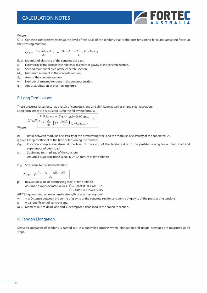
Where:σcp: Concrete compressive stress at the level of the c.o.g. of the tendons due to the post-tensioning force and actuating forces at the stressing moment.
EX φ : Modulus of elasticity of the concrete at j days.ε: Eccentricity of the tendon with reference to centre of gravity of the concrete section.Ic: Second moment of area of the concrete section.MX π : Maximum moment in the concrete section.AX : Area of the concrete section.v : Number of stressed tendons in the concrete section.φ: Age at application of prestressing force.
B. Long Term Losses
These prestress losses occur as a result of concrete creep and shrinkage as well as strand steel relaxation.Long term losses are calculated using the following formula:
Where:
n: Ratio between modulus of elasticity of the prestressing steel and the modulus of elasticity of the concrete: Ep/Ec
φ (t,to): Creep coefficient at the time of tensioning the tendons.σcp: Concrete compressive stress at the level of the c.o.g. of the tendons due to the post-tensioning force, dead load and superimposed dead load.εcs: Strain due to shrinkage of the concrete. Assumed as approximate value: εcs = 0.4 mm/m at time infinite.
σpr: Stress due to the steel relaxation:
: Relaxation value of prestressing steel at time infinite. Assumed as approximate values: = 0,029 at 60% of GUTS = 0,058 at 70% of GUTS(GUTS – guaranteed ultimate tensile strength of prestressing steel)yp = e: Distance between the centre of gravity of the concrete section and centre of gravity of the prestressing tendons.x = 0,8: coefficient of concrete age.Mcp: Moment due to dead load and superimposed dead load in the concrete section.
III. Tendon Elongation
Stressing operation of tendons is carried out in a controlled process where elongation and gauge pressures are measured at all steps.
X π X πε ε
δ Ø
τ τ X π π X σ τ τ π
X
X Ψ
X
∏ ∏ ∏ ∏ ∏ ∏
∏
π∏∏∏
ξπ
20
CALCULATION NOTES
v

The final elongation of a tendon, obtained by in situ calculation, is compared to the theoretical elongation value in order to check if the result is acceptable.The elongation of a post-tensioned tendon is assumed to be linear and is calculated with the use of the Hooke’s Law.
Where:∆l: Tendon elongation. l: Length of the tendon.ε.l: Tendon strain per unit of length.σs: Prestressing steel tensile stress (σs = P/Ap).
Due to the post-tensioning losses, the elongation is given as a function of the force exerted on every section of the tendon.
The elongation is proportional to the area under the curve of the post-tensioning force applied on the tendon (refer to figure 2).
Where:l: Length of the tendon.Px: Prestressing force at section “x” (Jacking force minus friction losses).
If the tendon has two live end anchors, it can be post-tensioned from both ends and thus the elongation of the tendon is now proportional to the area under the graph of both post-tensioning forces applied at both ends of the tendon, i.e. proportional to area A1+A2 (refer to figure 3).
IV. Anchor Block
The anchor block is defined as the highly stressed zone of concrete around the two end points of a post-tensioned tendon. It extends from the tendon anchorage to that section of the concrete at which linear distribution of stress is assumed to occur over the whole cross section.
For the design of the anchor blocks it is convenient to consider and check two different kinds of stresses and forces that are produced around the prestressing anchorage:
a) Bearing stresses.b) Bursting tensile forces.
Checking the bearing stresses will help to determine if the type of anchorage that has been chosen is valid and if the concrete compressive stress is acceptable.
Checking the bursting tensile forces will be necessary to evaluate the required anchorage bursting reinforcement.
Figure 2
Figure 3
Σ
∏
ξ
ξξ
21
CALCULATION NOTES

A. Bearing Stresses
The force that is transmitted through the bearing zone of the anchorage to the end block produces a high concrete compressive strength that can be evaluated as follows:
Where:P: Force applied on the anchorage.Ab: Bearing area of the anchorage.
The bearing area for the different trumpets of the MK4 system anchors is as listed in the following table.The compression tension in the bearing zone of the anchorage should be checked at two different stages:
• At transfer load (Jacking force)
Po: Maximum Jacking force applied to the anchorage at stressing.Ab: Bearing area of the anchorage.σco: Concrete compressive stress at transfer load.σco should not exceed the lowest of the following two values of cpo (permissible compressive concrete stress at transfer load).
Where:fci: Concrete compressive strength at the time of stressing.A’b: Area of the anchor block - Maximum area of concrete concentric with the anchorage and limited by the concrete borders of the section or another anchor block.
• At service load
σcs: Concrete compressive stress at service load.Ps: Prestressing force of the post-tensioned tendon at service.
Service load can be calculated deducting all type of prestress losses from the initial force at the anchorage zone.
Assumed Service load: 80% of the jacking force.
σcs should not exceed the lowest of the two following values of σcps (permissible compressive concrete stress at transfer load).
Anchorage Type
Anchorage Bearing Area
0,6”(15 mm) cm2
328
328
4/0,6” 328
328
5/0,6” 328
454
7/0,6” 454
582
9/0,6” 582
778
12/0,6” 778
981
1.218
15/0,6” 981
1.561
19/0,6” 1.218
1.561
1.561
24/0,6” 1.561
27/0,6” 2.050
31/0,6” 2.050
37/0,6” 2.487
43/0,6” 2.822
∏X
X X X
X X X
π
π
Ø
Ø
X σ∏
22
CALCULATION NOTES

Where: fc: Characteristic concrete compressive strength.
B. Bursting Tensile Forces
In the anchor block some severe transversal tensile forces appear that should be absorbed by steel reinforcement. These bursting tensile forces are produced from the curvature of the force line and are originated at the bearing zone of the anchorage where the force lines divert until they reach a uniform distribution.
Figure 6 shows the distribution of stresses due to the bursting tensile force, perpendicular to the centre line of the tendon.
To determine the value of the bursting tensile forces the following formula can be used.
Where:Z: Total bursting tensile force.fs: Design strength for the bursting reinforcement.Assumed design strength:400 MPa* (for 500 MPa Yield load Steel).As: Area of steel required for the bursting reinforcement.Po: Maximum jacking force at stressing.Ω : Shape factor. Assumed shape factors:Ω = 1 for anchors with a unique bearing plate without ribs.Ω = 0,93 for MK4 anchors with ribs.
*Note: Besides limiting the design strength for the bursting reinforcement to a maximum of 80% of the yield load, it is also convenient to limit the stress to a value corresponding to a steel strain of 0.002. This last limit has to be reduced to a steel strain of 0.001 on areas where the concrete cover is less than 50 mm.
Anchorage bursting reinforcement for the MK4-MS anchors is listed in the following table. To prepare the table, the following assumptions have been made:
Prestressing force = 85% of the characteristic strength of the tendon.Ratio between anchorage upper plate side and anchor block side (a1/d) = 0.5.Concrete compressive strength: 28 MPa (Cylindrical test sample)
Figure 6
X σ X πσ Ø
X σ πσX ØX
Ø Ø ∏ξδ
23
CALCULATION NOTES

Note: a1/d = 0,5 Concrete compressive strength = 28MPa
If the value of a1/d is not equal to 0.5 and the concrete compressive strength is different to 28MPa, the bursting reinforcement listed on the table does not apply and a new bursting reinforcement for the anchorage should be calculated.
Note: Changes may be made to the information contained in this brochure at any time as new techniques and/or materials are developed.
Anchorages Trumpet a1 D L P øC CIR. ø
15 mm mm mm mm mm mm units mm
T-4 170 155 240 80 210 4 10
T-4 170 155 240 80 210 4 10
4/0.6” T-4 170 155 240 80 210 4 12
T-4 170 155 240 80 210 4 12
5/0.6” T-5 170 155 240 60 210 5 12
T-5 194 150 285 95 260 4 14
7/0.6” T-5 194 150 280 70 260 5 14
T-6 220 175 320 80 310 5 14
9/0.6” T-6 220 175 325 65 310 6 14
T-7 254 200 360 90 350 5 16
12/0.6” T-7 254 200 375 75 350 6 16
T-8 282 235 400 80 400 6 16
T-19 314 230 440 110 440 5 20
15/0.6” T-8 282 235 420 60 400 8 16
TR-24 356 520 510 170 500 4 25
19/0.6” T-19 314 230 450 90 440 6 20
TR-24 356 520 510 170 500 4 25
TR-24 356 520 500 125 500 5 25
24/0.6” TR-24 356 520 500 125 500 5 25
27/0.6” TR-31 395 570 575 115 560 6 25
31/0.6” TR-31 395 570 570 95 560 7 25
37/0.6” TR-37 444 670 630 90 620 8 25
43/0.6” TR-43 490 1.100 720 80 680 10 25
24
CALCULATION NOTES
Note: a1/d=0,5 Concrete compressive strength = 28MPa


FORTEC AUSTRALIAABN 77 603 299 958
WWW.FORTECAUSTRALIA.COM.AU
HEAD OFFICE108 Motivation DriveWangara WA 6065T 08 6267 [email protected]
BRISBANEUnit 6, 15 Motorway CircuitOrmeau QLD 4208T 07 3106 4220
SYDNEY Level 5, 35 Saunders Street Pyrmont NSW 2009T 02 8318 4311
PORT HEDLAND11 Pinga Street Port Hedland WA 6721T 08 9185 6077
DARWIN30 Muramats Road East Arm NT 0822T 08 8901 7760
MELBOURNE 93-97 Remington Drive Dandenong South VIC 3175T 03 8787 5865
SYDNEYUnit 59, 7-9 Percy StreetAuburn NSW 2144T 02 8203 3860
KALGOORLIELot 33 Yarri Road Parkeston WA 6433T 08 9021 5277
ADELAIDE8 Walsh Avenue St Marys SA 5042T 08 7071 3550
KARRATHAUnit 1, 3890 Coolawanyah Road Karratha WA 6714T 08 9185 6077
GROUP COMPANY OFFICES


![IOMAC'17iomac.eu/iomac2017web/pdf/files/56_Bekker.pdf · and an acoustic tonoscope [8]. It comprises rubber sheeting stretched over a circular tube using a specially designed tensioning](https://img.dokumen.tips/doc/110x75/5e2ce18fc91af67e8c3c810c/iomac-and-an-acoustic-tonoscope-8-it-comprises-rubber-sheeting-stretched-over.jpg)


![Post Tensioning[1]](https://img.dokumen.tips/doc/110x75/543ffc0bafaf9fff098b4bcd/post-tensioning1.jpg)