Embed Size (px)
Citation preview

Catalog C-001 Rev. B

POSITRONIC INDUSTRIES
Unless specified otherwise, dimensional tolerances are:1] ±0.001 inches [0.03 mm] for male contact mating diameters.2] ±0.003 inches [0.08 mm] for contact termination diameters.3] ±0.005 inches [0.13 mm] for all other diameters.4] ±0.015 inches [0.38 mm] for all other dimensions.5] ±0.0015 inches [0.038 mm] for all press-fit contact terminations.
Products described within this catalog may be protected by one or more of the following US. patents:
#4,721,472 #4,900,261 #5,255,580 #5,329,697 #6,260,268
Patented in Canada, 1992
About Us
Founded in 1966, Positronic Industries is a vertically integrated manufacturer of high quality interconnect products.Positronic has earned the worldwide reputation as a service oriented, quick-reaction, top quality connector supplier. We are committed to maintaining this reputation by continuous implementation of our Complete Capability concept.
Complete Capability
Design & Development
• Designs new connectors and modifies existing connectors to meet industry requirements• Continuously conducts marketing studies to identify industry needs for new products • Ongoing interest in unique connector designs
Tooling
• Tooling support for all manufacturing areas within company• Provides 80% of new tooling, punch press dies, molds, jigs and fixtures used at Positronic factory locations worldwide
Machining
• Automatic screw machines produce finely crafted contacts and hardware for connector bodies
• Trained technicians operate machines from Tornos, Bechler and Brown & Sharpe
Molding
• Molds all plastic connector components such as insulators, hoods, angle brackets and more • Overmold capability available
Plating
• Applies gold and other metal finishes to connector components to any required thickness• Plating conforms to all military specifications
Quality Assurance Lab
• Quality assurance system certified to ISO 9001• Maintains aggressive TQM program• Able to test to IEC, EIA, UL, MIL-DTL-24308, MIL-DTL-28748, MIL-C-39029 and MIL-C-85049 requirements
Finished Stock Inventory
• Each main factory location maintains a large inventory of connector components and accessories• Same day shipments available on many standard connector products• Stocking agreements available for qualified customers
Worldwide Sales & Service
• Responsive attitude toward customer needs• Fully trained sales staff located worldwide
Positronic Industries believes the data contained herein to be reliable. Since the technical information is given free of charge, the User employssuch information at his own discretion and risk. Positronic Industries assumes no responsibility for results obtained or damages incurred from useof such information in whole or in part.
Positronic Industries’ FEDERAL SUPPLY CODE [Cage Code] FOR MANUFACTURERS is 28198
Machining
Molding
Finished Stock Inventory

CONNECTOR DESCRIPTIONS
MELO-D and EURO-D CONNECTORSMD Series and ED Series. Fixed contact, 7.5 amperenominal rating. Solder cup, wrap post, and printed boardcontact terminations for inch and metric printed board holepatterns. Six connector variants, 9 through 50 contacts.Professional quality connectors to IEC 807-2, PerformanceLevel Two.
SOLI-D CONNECTORSSD Series. Removable contact, 7.5 ampere nominalrating. Solder cup, crimp and straight printed board mountcontact terminations. Five connector variants, 9 through50 contacts. Professional quality connectors to IEC 807-3,Performance Level Two.
DENSI-D CONNECTORSDD Series. Removable contact, five ampere nominal rat-ing. Solder cup, crimp and straight and 90° printed boardcontact terminations. Six connector variants, 15 through104 contacts. Military quality connectors qualified to MIL-DTL-24308 and MIL-C-39029.
LOW COST HIGH DENSITY CONNECTORSODD Series. Removable contact, five ampere nominal rat-ing. Solder cup, crimp and straight and 90° printed boardcontact terminations. Six connector variants, 15 through104 contacts. Professional quality connectors.
RHAPSO-D CONNECTORSRD Series. Removable contact, 7.5 ampere nominal rat-ing. Crimp contact terminations. Six connector variants, 9 through 50 contacts. Military quality connectors qualifiedto MIL-DTL-24308 and MIL-C-39029. IEC 807-3,Performance Level One.
LOW COST STANDARD DENSITY CONNECTORSORD Series. Removable contact, 7.5 ampere nominalrating. Crimp contact terminations. Six connector variants,9 through 50 contacts. Professional quality connectors.
HARMO-D CONNECTORSHDC Series. Fixed contact, 7.5 ampere nominal rating.Solder cup, wrap post and straight and 90° printed boardcontact terminations. Five connector variants, 9 through50 contacts. Military quality connectors qualified to MIL-DTL-24308, IEC 807-2, Performance Level One.
PRESS-FIT CONNECTORSPCD Series. Machined contact, compliant termination,repairable, 7.5 ampere nominal rating. Five connectorvariants, 9 through 50 contacts. Professional quality con-nectors, conform to IEC 807-2, Performance Level Two.
HIGH DENSITY PRESS-FIT CONNECTORSPCDD Series. Machined contact, compliant termination,repairable, 5 ampere nominal rating. Five connectorvariants, 15 through 104 contacts. Professional qualityconnectors.

MATED CONNECTORMD / ED SERIES
SD SERIESDD SERIES
ODD SERIESRD SERIES
T A B L E O F C O N T E N T S
Exploded Views of Typical Mated Subminiture-D Connector Assemblies . . . . . . . . . . . . . . . . . . . . . . . . . . . . . . 1
Connector Component Description and Terminology . . . . . . . . . . . . . . . . . . . . . . . . . . . . . . . . . . . . . . . . . . . . . . 2
M A T E D C O N N E C T O R A S S E M B L I E S
Technical Characteristics . . . . . . . . . . . . . . . . . . . . . . . . . . . . . . . . . . . . . . . . . . . . . . . . . . . . . . . . . . . . . . . . . . . . 3
Contact Variants and Standard Shell Assembly . . . . . . . . . . . . . . . . . . . . . . . . . . . . . . . . . . . . . . . . . . . . . . . . . . 4
Solder Cup Connector, Straight Printed Board Mount Connector, Ferrite Inductor Bar For EMI/RFI Noise Suppression, and Wrap Post Connector . . . . . . . . . . . . . . . . . . . . . . . . 5
90º Printed Board Mount Connectors - Code 5 and Code 52. . . . . . . . . . . . . . . . . . . . . . . . . . . . . . . . . . . . . . . . 6
90º Printed Board Mount Connectors - Code 4 and 90º and Straight Printed Board Contact Hole Pattern . . . . 7
90º Printed Board Mount Connectors - Code 42 and Code 44. . . . . . . . . . . . . . . . . . . . . . . . . . . . . . . . . . . . . . . 8
90º and Straight Printed Board Contact Hole Pattern for Code 42 and 52 . . . . . . . . . . . . . . . . . . . . . . . . . . . . . . 9
Ordering Information . . . . . . . . . . . . . . . . . . . . . . . . . . . . . . . . . . . . . . . . . . . . . . . . . . . . . . . . . . . . . . . . . . . . . . . 10
M D / E D S E R I E S
Technical Characteristics . . . . . . . . . . . . . . . . . . . . . . . . . . . . . . . . . . . . . . . . . . . . . . . . . . . . . . . . . . . . . . . . . . . . 11
Contact Variants and Standard Shell Assembly . . . . . . . . . . . . . . . . . . . . . . . . . . . . . . . . . . . . . . . . . . . . . . . . . . 12
Crimp Contacts and Reels for Automatic Feed Pneumatic Crimp Tools . . . . . . . . . . . . . . . . . . . . . . . . . . . . . . . . 13
Straight Printed Board Mount Contacts . . . . . . . . . . . . . . . . . . . . . . . . . . . . . . . . . . . . . . . . . . . . . . . . . . . . . . . . . 14
Straight Printed Board Contact Hole Pattern. . . . . . . . . . . . . . . . . . . . . . . . . . . . . . . . . . . . . . . . . . . . . . . . . . . . . 15
Crimping Information for RD and SD Series Crimp Contacts and Crimping Installation Tools . . . . . . . . . . . . . . . 16-18
Ordering Information . . . . . . . . . . . . . . . . . . . . . . . . . . . . . . . . . . . . . . . . . . . . . . . . . . . . . . . . . . . . . . . . . . . . . . . 19
S D S E R I E S
Technical Characteristics . . . . . . . . . . . . . . . . . . . . . . . . . . . . . . . . . . . . . . . . . . . . . . . . . . . . . . . . . . . . . . . . . . . . 20
Contact Variants and Standard Shell Assembly . . . . . . . . . . . . . . . . . . . . . . . . . . . . . . . . . . . . . . . . . . . . . . . . . . 21
Crimp Contacts, Solder Cup Contacts and Reels for Automatic Feed Pneumatic Crimp Tools . . . . . . . . . . . . . . 22
Straight Printed Board Mount Contacts . . . . . . . . . . . . . . . . . . . . . . . . . . . . . . . . . . . . . . . . . . . . . . . . . . . . . . . . . 23
90º Printed Board Mount Connectors - Code 4. . . . . . . . . . . . . . . . . . . . . . . . . . . . . . . . . . . . . . . . . . . . . . . . . . . 24
90º and Straight Printed Board Contact Hole Pattern . . . . . . . . . . . . . . . . . . . . . . . . . . . . . . . . . . . . . . . . . . . . . . 25
Crimping Information for DD and ODD Series Crimp Contacts and Crimping Installation Tools . . . . . . . . . . . . . 26-28
Ordering Information . . . . . . . . . . . . . . . . . . . . . . . . . . . . . . . . . . . . . . . . . . . . . . . . . . . . . . . . . . . . . . . . . . . . . . . 29
D D S E R I E S
Technical Characteristics . . . . . . . . . . . . . . . . . . . . . . . . . . . . . . . . . . . . . . . . . . . . . . . . . . . . . . . . . . . . . . . . . . . . 30
Contact Variants and Standard Shell Assembly . . . . . . . . . . . . . . . . . . . . . . . . . . . . . . . . . . . . . . . . . . . . . . . . . . 31
Crimp Contacts, Solder Cup Contacts and Straight Printed Board Mount Connector . . . . . . . . . . . . . . . . . . . . . 32
90º Printed Board Mount Connectors - Code 5 and Code 4. . . . . . . . . . . . . . . . . . . . . . . . . . . . . . . . . . . . . . . . . 33
Fixed Contact Solder Cup Connector, 90º Printed Board Mount Connector - Code 5 and Code 4 . . . . . . . . . . . 34
90º and Straight Printed Board Contact Hole Pattern . . . . . . . . . . . . . . . . . . . . . . . . . . . . . . . . . . . . . . . . . . . . . . 35
Crimping Installation Tools . . . . . . . . . . . . . . . . . . . . . . . . . . . . . . . . . . . . . . . . . . . . . . . . . . . . . . . . . . . . . . . . . . . 36
Reels for Automatic Feed Pneumatic Crimp Tools and Ordering Information . . . . . . . . . . . . . . . . . . . . . . . . . . . 37
O D D S E R I E S

ORD
SERI
ESHD
C SE
RIES
PCD
SERI
ESPC
DD S
ERIE
SMI
L LI
STIN
GS
Technical Characteristics . . . . . . . . . . . . . . . . . . . . . . . . . . . . . . . . . . . . . . . . . . . . . . . . . . . . . . . . . . . . . . . . . . . . 44
Contact Variants and Standard Shell Assembly . . . . . . . . . . . . . . . . . . . . . . . . . . . . . . . . . . . . . . . . . . . . . . . . . . 45
Crimp Contacts and Reels for Automatic Feed Pneumatic Crimp Tools . . . . . . . . . . . . . . . . . . . . . . . . . . . . . . . . 46
Ordering Information . . . . . . . . . . . . . . . . . . . . . . . . . . . . . . . . . . . . . . . . . . . . . . . . . . . . . . . . . . . . . . . . . . . . . . . 47
O R D S E R I E S
Technical Characteristics . . . . . . . . . . . . . . . . . . . . . . . . . . . . . . . . . . . . . . . . . . . . . . . . . . . . . . . . . . . . . . . . . . . . 48
Contact Variants and Standard Shell Assembly . . . . . . . . . . . . . . . . . . . . . . . . . . . . . . . . . . . . . . . . . . . . . . . . . . 49
Solder Cup Connector, Straight Printed Board Mount Connector, and Wrap Post Connector . . . . . . . . . . . . . . . 50
90º Printed Board Mount Connectors - Code 5 and Code 42. . . . . . . . . . . . . . . . . . . . . . . . . . . . . . . . . . . . . . . . 51
90º and Straight Printed Board Contact Hole Pattern . . . . . . . . . . . . . . . . . . . . . . . . . . . . . . . . . . . . . . . . . . . . . 52
Ordering Information . . . . . . . . . . . . . . . . . . . . . . . . . . . . . . . . . . . . . . . . . . . . . . . . . . . . . . . . . . . . . . . . . . . . . . . 53
H D C S E R I E S
Technical Characteristics . . . . . . . . . . . . . . . . . . . . . . . . . . . . . . . . . . . . . . . . . . . . . . . . . . . . . . . . . . . . . . . . . . . . 54
Contact Variants and Standard Shell Assembly . . . . . . . . . . . . . . . . . . . . . . . . . . . . . . . . . . . . . . . . . . . . . . . . . . 55
Bi-Spring Compliant Press-Fit Connector and Omega Compliant Press-Fit Connector . . . . . . . . . . . . . . . . . . . . 56
Compliant Press-Fit Connector Printed Board Contact Hole Pattern andPCD Series Press-Fit Connectors Installation Tools . . . . . . . . . . . . . . . . . . . . . . . . . . . . . . . . . . . . . . . . . . . . . . . 57
Ordering Information and Replacement Contacts Part Numbers . . . . . . . . . . . . . . . . . . . . . . . . . . . . . . . . . . . . . 58
P C D S E R I E S
Technical Characteristics . . . . . . . . . . . . . . . . . . . . . . . . . . . . . . . . . . . . . . . . . . . . . . . . . . . . . . . . . . . . . . . . . . . . 59
Contact Variants and Standard Shell Assembly . . . . . . . . . . . . . . . . . . . . . . . . . . . . . . . . . . . . . . . . . . . . . . . . . . 60
Omega Compliant Press-Fit Connector and PCDD Series Press-Fit Connectors Installation Tools. . . . . . . . . . . 61
Compliant Press-Fit Connector Printed Board Contact Hole Pattern . . . . . . . . . . . . . . . . . . . . . . . . . . . . . . . . . . 62
Ordering Information and Replacement Contacts Part Numbers . . . . . . . . . . . . . . . . . . . . . . . . . . . . . . . . . . . . . 63
P C D D S E R I E S
MIL-DTL-24308 / MIL-C-39029 / MIL-C-85049 Qualified Product Listings . . . . . . . . . . . . . . . . . . . . . . . . . . . . . . 64-73
M I L Q U A L I F I E D P R O D U C T S
T A B L E O F C O N T E N T S . . . con t inued
Technical Characteristics . . . . . . . . . . . . . . . . . . . . . . . . . . . . . . . . . . . . . . . . . . . . . . . . . . . . . . . . . . . . . . . . . . . . 38
Contact Variants and Standard Shell Assembly . . . . . . . . . . . . . . . . . . . . . . . . . . . . . . . . . . . . . . . . . . . . . . . . . . 39
Crimp Contacts - Closed Crimp Barrel and Reels for Automatic Feed Pneumatic Crimp Tools . . . . . . . . . . . . . . 40
Crimp Contacts - 18 AWG and Thermocouple Contacts. . . . . . . . . . . . . . . . . . . . . . . . . . . . . . . . . . . . . . . . . . . . 41
Crimping Installation Tools . . . . . . . . . . . . . . . . . . . . . . . . . . . . . . . . . . . . . . . . . . . . . . . . . . . . . . . . . . . . . . . . . . . 42
Ordering Information . . . . . . . . . . . . . . . . . . . . . . . . . . . . . . . . . . . . . . . . . . . . . . . . . . . . . . . . . . . . . . . . . . . . . . . 43
R D S E R I E S

EXPLODED VIEWS OF TYPICAL MATEDSUBMINIATURE-D
CONNECTOR ASSEMBLIESD-Sub
Positronic Industries, Inc.www.connectpositronic.com
1
DD62M000E6X
DD62F0S50T6X
HDC25F5R7NV30
RD25M10LVL0
M24308/4-3F
M24308/23-39F
DD44F3S000-759.0
DD44M0000X-759.1
M24308/26-1
M24308/25-6
M85049/48-1-3
MATED CONNECTOR

D-SubEXPLODED VIEWS OF TYPICAL MATED
SUBMINIATURE-DCONNECTOR ASSEMBLIES
2
Positronic Industries, Inc.www.connectpositronic.com
CONNECTOR COMPONENT DESCRIPTION AND TERMINOLOGY
SD9M00Z0Z
MD9F5R80TX
A-1 – Male and female signal contacts, size 22. Terminations may be crimp, solder cup andprinted board mount.
A-2 – Male and female signal contacts, size 20. Terminations may be crimp, solder cup, wrappost, press-fit and printed board mount.
B-1 – Unloaded connector insulators, male and female. Insulator retention system retains allcontact termination types. Insulator may be used as a free or fixed connector.
B-2 – Loaded connector insulators, male and female. Insulators may be preloaded per cus-tomer requirements with contacts having terminations of 90° or straight solder printedboard mount, wrap post, solder cup and press-fit. Insulator contact positions may beselectively loaded with contacts. Connectors are normally fixed panel or printed boardconnectors.
C-1 – Fixed female jackscrews are the stationary threaded members of the non-polarizedjackscrew system.
C-2 – Fixed male and female jackscrews are the stationary threaded members of the polarizedjackscrew system.
C-3 – Rotating male jackscrews and screwlocks are the rotating threaded members of the non-polarized jackscrew system.
C-4 – Rotating male and female jackscrews are the rotating threaded members of the polarizedjackscrew system.
C-5 – Vibration locking system consists of lock tabs on fixed connector and slide lock lever onfree cable connector.
C-6 – Blind mating connector system with pilot probes on free connector and receptacle guideson panel mounted fixed connector.
C-7 – Cable adapters [Hoods] are used on the free cable connector to provide cable supportand contact protection.
C-8 – Knobs of the polarized rotating jackscrew system are affixed to the rotating jackscrew bya set screw.
MATE
D CO
NNEC
TOR
Size 20 Contacts, FixedProfessional Quality
ConnectorsIEC Publication 807-2
Performance Level TwoU.L. Recognized CSA Recognized
File #E49351 File #LR54219
TelecommunicationU.L. File #14098
D-SubPROFESSIONAL QUALITY,
FIXED CONTACTSUBMINIATURE-D CONNECTORS
FOR SHELTERED INDOOR/OUTDOOR ENVIRONMENTAL APPLICATIONSPositronic Industries, Inc.www.connectpositronic.com
3
MD / ED SERIES
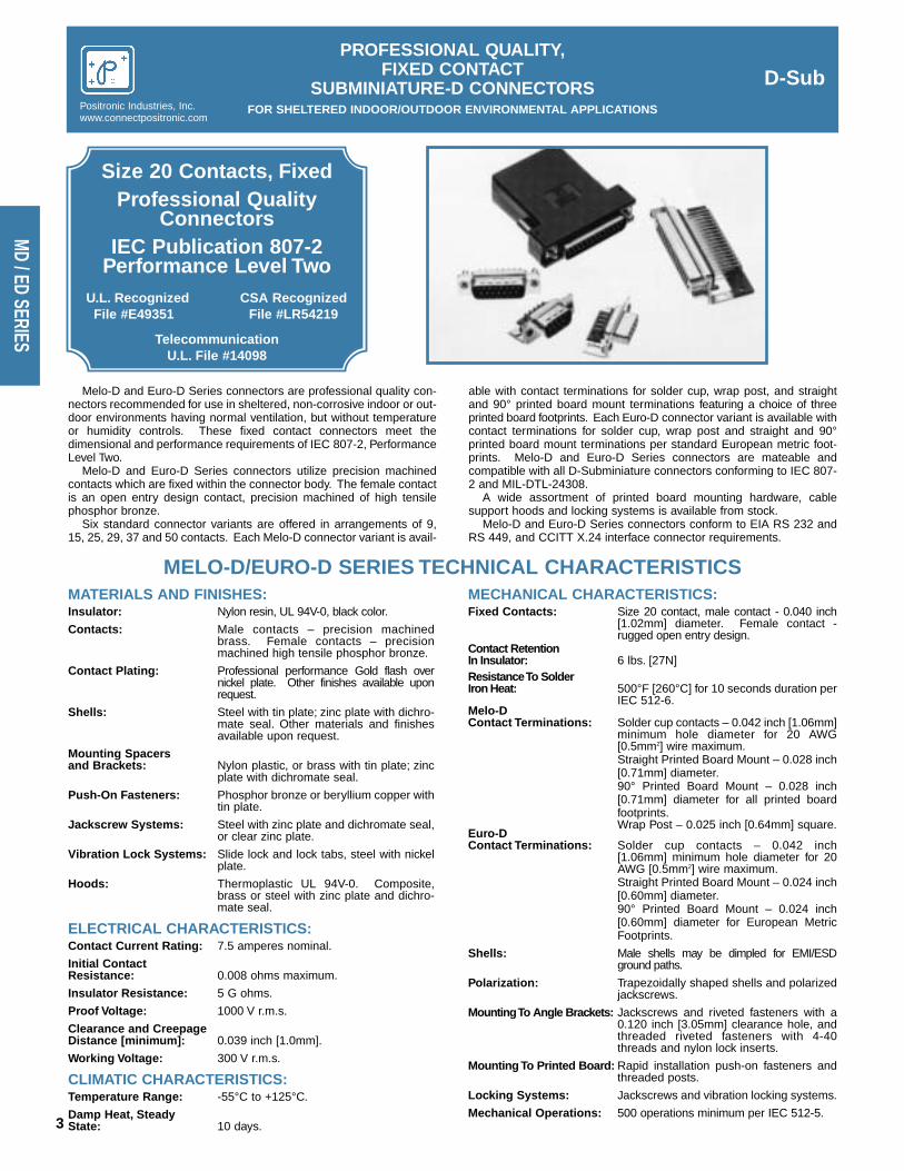
Melo-D and Euro-D Series connectors are professional quality con-nectors recommended for use in sheltered, non-corrosive indoor or out-door environments having normal ventilation, but without temperatureor humidity controls. These fixed contact connectors meet thedimensional and performance requirements of IEC 807-2, PerformanceLevel Two.
Melo-D and Euro-D Series connectors utilize precision machinedcontacts which are fixed within the connector body. The female contactis an open entry design contact, precision machined of high tensilephosphor bronze.
Six standard connector variants are offered in arrangements of 9,15, 25, 29, 37 and 50 contacts. Each Melo-D connector variant is avail-
able with contact terminations for solder cup, wrap post, and straightand 90° printed board mount terminations featuring a choice of threeprinted board footprints. Each Euro-D connector variant is available withcontact terminations for solder cup, wrap post and straight and 90°printed board mount terminations per standard European metric foot-prints. Melo-D and Euro-D Series connectors are mateable andcompatible with all D-Subminiature connectors conforming to IEC 807-2 and MIL-DTL-24308.
A wide assortment of printed board mounting hardware, cablesupport hoods and locking systems is available from stock.
Melo-D and Euro-D Series connectors conform to EIA RS 232 andRS 449, and CCITT X.24 interface connector requirements.
MELO-D/EURO-D SERIES TECHNICAL CHARACTERISTICSMATERIALS AND FINISHES:Insulator: Nylon resin, UL 94V-0, black color.
Contacts: Male contacts – precision machinedbrass. Female contacts – precisionmachined high tensile phosphor bronze.
Contact Plating: Professional performance Gold flash overnickel plate. Other finishes available uponrequest.
Shells: Steel with tin plate; zinc plate with dichro-mate seal. Other materials and finishesavailable upon request.
Mounting Spacers and Brackets: Nylon plastic, or brass with tin plate; zinc
plate with dichromate seal.
Push-On Fasteners: Phosphor bronze or beryllium copper withtin plate.
Jackscrew Systems: Steel with zinc plate and dichromate seal,or clear zinc plate.
Vibration Lock Systems: Slide lock and lock tabs, steel with nickelplate.
Hoods: Thermoplastic UL 94V-0. Composite,brass or steel with zinc plate and dichro-mate seal.
ELECTRICAL CHARACTERISTICS:Contact Current Rating: 7.5 amperes nominal.
Initial ContactResistance: 0.008 ohms maximum.
Insulator Resistance: 5 G ohms.
Proof Voltage: 1000 V r.m.s.
Clearance and CreepageDistance [minimum]: 0.039 inch [1.0mm].
Working Voltage: 300 V r.m.s.
CLIMATIC CHARACTERISTICS:Temperature Range: -55°C to +125°C.
Damp Heat, Steady State: 10 days.
MECHANICAL CHARACTERISTICS:Fixed Contacts: Size 20 contact, male contact - 0.040 inch
[1.02mm] diameter. Female contact -rugged open entry design.
Contact RetentionIn Insulator: 6 lbs. [27N]Resistance To Solder Iron Heat: 500°F [260°C] for 10 seconds duration per
IEC 512-6.Melo-DContact Terminations: Solder cup contacts – 0.042 inch [1.06mm]
minimum hole diameter for 20 AWG[0.5mm2] wire maximum.Straight Printed Board Mount – 0.028 inch[0.71mm] diameter.90° Printed Board Mount – 0.028 inch[0.71mm] diameter for all printed boardfootprints.Wrap Post – 0.025 inch [0.64mm] square.
Euro-DContact Terminations: Solder cup contacts – 0.042 inch
[1.06mm] minimum hole diameter for 20AWG [0.5mm2] wire maximum.Straight Printed Board Mount – 0.024 inch[0.60mm] diameter.90° Printed Board Mount – 0.024 inch[0.60mm] diameter for European MetricFootprints.
Shells: Male shells may be dimpled for EMI/ESDground paths.
Polarization: Trapezoidally shaped shells and polarizedjackscrews.
Mounting To Angle Brackets: Jackscrews and riveted fasteners with a0.120 inch [3.05mm] clearance hole, andthreaded riveted fasteners with 4-40threads and nylon lock inserts.
Mounting To Printed Board: Rapid installation push-on fasteners andthreaded posts.
Locking Systems: Jackscrews and vibration locking systems.
Mechanical Operations: 500 operations minimum per IEC 512-5.

222120
31 2
2423 26 2725 3028 29 32 3331
654 87 1211109 1413
3634 35 37
171615 1918
383534 3736 39 40 4341 42
5
18 20 2119
21 43
242322 272625
76 1098
45 4644 4947 48 50
333028 29 3231
131211 161514 17
9876
1 542 3
15141211109 13
321 87654
14
1 2
2524232221201817 191615
876543 1312109 11
21
11 12
20
21
26
1716
242322
13 14 15
25 2927 28
1918
76543 1098
C
A
E
BB1
DD1
KM
G
H
0.220 [5.59]Max.
10° Typ.
0.120±0.010 [3.05±0.25]
0.032 [0.81]Total diametral float
Ø0.086+0.005-0.000 [Ø2.18+0.13
-0.00]Mounting hole, two places
0.036±0.008[0.91±0.20]
0.050±0.010[1.27±0.25]
for stainless steel shell (0 option)
two places (02 option)
Ø0.120±0.005 [Ø3.05±0.13] Mounting hole, two places
Ø0.120±0.005 [Ø3.05±0.13] Mounting hole, two places
Ø0.154 [3.91] Mounting hole,
D-SubPROFESSIONAL QUALITY,
FIXED CONTACTSUBMINIATURE-D CONNECTORS
FOR SHELTERED INDOOR/OUTDOOR ENVIRONMENTAL APPLICATIONS
4DIMENSIONS ARE IN INCHES [MILLIMETERS].ALL DIMENSIONS ARE SUBJECT TO CHANGE.
Positronic Industries, Inc.www.connectpositronic.com
MD /
ED S
ERIE
S
CONTACT VARIANTSFACE VIEW OF MALE OR REAR VIEW OF FEMALE
SIZE 9 SIZE 15 SIZE 25
SIZE 29 SIZE 37 SIZE 50
STANDARD SHELL ASSEMBLY
OPTIONAL SHELL ASSEMBLY WITH UNIVERSAL FLOAT MOUNTS [F]OPTIONAL SHELL ASSEMBLY [0, 02]
CONNECTORVARIANT SIZES
A±0.015[0.38]
B±0.005[0.13]
B1±0.005[0.13]
C±0.005[0.13]
D±0.005[0.13]
D1±0.005[0.13]
E±0.015[0.38]
G±0.010[0.25]
H±0.010[0.25]
K±0.005[0.13]
M±0.010[0.25]
9 M1.213[30.81]
0.666[16.92]
0.984[24.99]
0.329[8.36]
0.494[12.55]
0.759[19.28]
0.422[10.72]
0.233[5.92]
0.422[10.72]
9 F1.213[30.81]
0.643[16.33]
0.984[24.99]
0.311[7.90]
0.494[12.55]
0.759[19.28]
0.422[10.72]
0.243[6.17]
0.429[10.90]
15 M1.541[39.14]
0.994[25.25]
1.312[33.32]
0.329[8.36]
0.494[12.55]
1.083[27.51]
0.422[10.72]
0.233[5.92]
0.422[10.72]
15 F1.541[39.14]
0.971[24.66]
1.312[33.32]
0.311[7.90]
0.494[12.55]
1.083[27.51]
0.422[10.72]
0.243[6.17]
0.429[10.90]
25 M2.088[53.04]
1.534[38.96]
1.852[47.04]
0.329[8.36]
0.494[12.55]
1.625[41.28]
0.422[10.72]
0.230[5.84]
0.426[10.82]
25 F2.088[53.04]
1.511[38.38]
1.852[47.04]
0.311[7.90]
0.494[12.55]
1.625[41.28]
0.422[10.72]
0.243[6.17]
0.429[10.90]
29 M1.770[44.96]
1.274[32.36]
1.534[38.96]
0.450[11.43]
0.605[15.37]
1.322[33.58]
0.539[13.69]
0.217[5.51]
0.426[10.82]
29 F1.770[44.96]
1.251[31.78]
1.534[38.96]
0.431[10.95]
0.605[15.37]
1.322[33.58]
0.539[13.69]
0.237[6.02]
0.429[10.90]
37 M2.729[69.32]
2.182[55.42]
2.500[63.50]
0.329[8.36]
0.494[12.55]
2.272[57.71]
0.422[10.72]
0.230[5.84]
0.426[10.82]
37 F2.729[69.32]
2.159[54.84]
2.500[63.50]
0.311[7.90]
0.494[12.55]
2.272[57.71]
0.422[10.72]
0.243[6.17]
0.429[10.90]
50 M2.635[66.93]
2.079[52.81]
2.406[61.11]
0.441[11.20]
0.605[15.37]
2.178[55.32]
0.534[13.56]
0.230[5.84]
0.426[10.82]
50 F2.635[66.93]
2.064[52.43]
2.406[61.11]
0.423[10.74]
0.605[15.37]
2.178[55.32]
0.534[13.56]
0.243[6.17]
0.429[10.90]

Swaged spacer withpush-on fastenerphosphor bronze
Fixed female jackscrews
ØD
0.225 [5.71]
L
0.010 [0.25]MIN.
Fixedfemale
jackscrews
0.495 [12.57]
0.720 [18.29]
0.025 [0.64] Sq.
0.135±0.005[3.43±0.13]Ferrite inductor bar
L
Swaged spacer with push-onfastener phosphor bronze
A
Fixed female jackscrews
0.010 [0.25] Min.
0.352 [8.94]
20 AWG max.[0.5 mm ]
0.135 [3.43]
2
Fixed female jackscrews
Fixed malejackscrew
Fixed femalejackscrew
D-SubPROFESSIONAL QUALITY,
FIXED CONTACTSUBMINIATURE-D CONNECTORS
FOR SHELTERED INDOOR/OUTDOOR ENVIRONMENTAL APPLICATIONSPositronic Industries, Inc.www.connectpositronic.com
5 DIMENSIONS ARE IN INCHES [MILLIMETERS].ALL DIMENSIONS ARE SUBJECT TO CHANGE.
MD / ED SERIES
SOLDER CUP CONNECTOR
Typical Part Number: MD15M200T6ZTypical Part Number: ED15M200T2Z
Typical Part Number: MD25F3S60T0
Fixed male and female polarized jackscrews available.Specify code T6 in step 7 of ordering information.
For solder cup contacts, specify code 2 in step 4
of ordering information.
For wrap post contacts,specify code 6 in step 4of ordering information.
STRAIGHT PRINTED BOARD MOUNT CONNECTORCODE
NUMBERL
30.150[3.81]
320.375[9.53]
360.236[5.99]
FERRITE INDUCTOR BAR FOR EMI/RFI NOISE SUPPRESSION
FILTERING CHARACTERISTICS
ØD
0.028[0.71]
0.028[0.71]
0.024[0.61]
AT
TE
NU
AT
ION
[d
B]
IMP
ED
AN
CE
[O
HM
S]
FREQUENCY
*NO-LOAD CONDITION
MD25M6S50T0
Typical Part Number: MD15F600T20
WRAP POST CONNECTOR
90° PRINTED BOARD MOUNT CONNECTOR
STRAIGHT PRINTED BOARD MOUNT CONNECTOR
MATERIAL: NICKEL ZINC CERAMIC.
SERIES CODE NO.
MD 32
MD 4
MD 59
A
0.375 [9.53]
------
------
L
0.240 [6.10]
------
------
MD 6 0.375 [9.53] 0.360 [9.14]
ED 36 0.375 [9.53] 0.101 [2.57]
ED 6 0.375 [9.53] 0.360 [9.14]
DD 32 0.515 [13.08] 0.165 [4.19]
ODD 32 0.375 [9.53] 0.165 [4.19]
ODD 5 ------ ------
HDC 32 0.375 [9.53] 0.240 [6.10]
HDC 36 0.375 [9.53] 0.101 [2.57]
HDC 6 0.375 [9.53] 0.360 [9.14]
IMPEDANCE
ATTENUATION*
For straight printed board mountcontacts, specify code number in
step 4 of ordering information.
Specify code F or Q in step 6 of orderinginformation. F for ferrite inductor and Qfor ferrite inductor with push-on fastener.

Specify code 59in step 4 of
ordering information 0.112 [2.84] Typ.
D
0.112 [2.84] Typ.
0.112 [2.84] Typ.
D
AB
±0.008[0.20]jackscrews
female Fixed
X 0.233 [5.92]Oval hole Typ.
0.125 [3.18]
E
C
713 12 11 10 9 8
2021222325 24
6 5 4 3 2 1
141515171819
Numbering shown is rear view of male and face view of female.
Ø0.028 [0.71]
0.160 [4.06]Nominal
0.112 [2.84] Typ.
0.112 [2.84] Typ.
D
jackscrews female Fixed B
±0.008[0.20]
A
C
Specify code 5in step 4 of
ordering informationD
0.112 [2.84] Typ.
Numbering shown is rear view of male and face view of female.
0.160 [4.06]Nominal
Ø0.028 [0.71]
25 192021222324
13 7 689101112
1415151718
12345
Push-on fastenerberyllium copper
D-SubPROFESSIONAL QUALITY,
FIXED CONTACTSUBMINIATURE-D CONNECTORS
FOR SHELTERED INDOOR/OUTDOOR ENVIRONMENTAL APPLICATIONS
6DIMENSIONS ARE IN INCHES [MILLIMETERS].ALL DIMENSIONS ARE SUBJECT TO CHANGE.
Positronic Industries, Inc.www.connectpositronic.com
MD /
ED S
ERIE
S
90° PRINTED BOARD MOUNT CONNECTORCODE 5, 0.283 [7.19] CONTACT EXTENSION
MD**5R4*** 0.283 [7.19] CONTACT EXTENSION
PART NUMBER A B C D
MD9*5R4***1.204[30.58]
0.984[24.99]
0.339[8.61]
0.283[7.19]
MD15*5R4***1.532[38.91]
1.312[33.32]
0.339[8.61]
0.283[7.19]
MD25*5R4***2.072[52.63]
1.852[47.04]
0.339[8.61]
0.283[7.19]
MD29*5R4***1.754[44.55]
1.534[38.96]
0.395[10.03]
0.283[7.19]
MD37*5R4***2.720[69.09]
2.500[63.50]
0.339[8.61]
0.283[7.19]
MD50*5R4***2.626[66.70]
2.406[61.11]
0.395[10.03]
0.283[7.19]
Typical Part Number:MD25M59B0T2X
Typical Part Number:MD29M59B0T2X
Typical Part Number:MD50M5R4NT2X
Typical Part Number:MD25M5R4NT2X
90° PRINTED BOARD MOUNT CONNECTORCODE 59, 0.545 [13.84] CONTACT EXTENSION
MD50*59B***2.626[66.70]
2.406[61.11]
0.275[6.99]
0.545[13.84]
PART NUMBER A B C D
MD9*59B***1.204[30.58]
0.984[24.99]
0.275[6.99]
0.545[13.84]
MD15*59B***1.532[38.91]
1.312[33.32]
0.275[6.99]
0.545[13.84]
MD25*59B***2.072[52.63]
1.852[47.04]
0.275[6.99]
0.545[13.84]
MD29*59B***1.754[44.55]
1.534[38.96]
0.275[6.99]
0.545[13.84]
MD37*59B***2.720[69.09]
2.500[63.50]
0.275[6.99]
0.545[13.84]
0.657[16.69]
E
0.601[15.27]
0.601[15.27]
0.601[15.27]
0.657[16.69]
0.601[15.27]
MD**59B*** 0.545 [13.84] CONTACT EXTENSION
0.216 [5.49]
0.108 [2.74] Typ.
0.162 [4.11]
0.054 [1.37]Typ.
Sym. 0.656[16.66]
0.378 [9.60]
0.324 [8.23]
0.108 [2.74] Typ.
0.054 [1.37]Typ.
0.926 [23.52] 0.652 [16.56]Sym. Sym.
0.109 [2.77]Typ.
0.598 [15.19]
0.055 [1.40]Typ.
1.250 [31.75] 0.978 [24.84]
0.924 [23.47]
0.055 [1.40]Typ.
0.109[2.77]Typ.
Sym. 1.203[30.56]
0.870 [22.10]
0.109[2.77]Typ.
0.055 [1.40]Typ.
Sym.
0.815 [20.70]
Sym. 0.432[10.97]
0.767[19.48]
0.054[1.37]Typ.
0.486 [12.34]
0.108 [2.74]Typ.
0.492[12.50]
0.112[2.84]
0.112[2.84]
0.112[2.84]
0.112[2.84]
0.224[5.69]
0.112[2.84]
0.224[5.69]
0.112[2.84]
Specify code 4in step 4 of
ordering information 0.112 [2.84] Typ.
D
0.112 [2.84] Typ.
0.112 [2.84] Typ.
D
713 12 11 10 9 8
2021222325 24
6 5 4 3 2 1
141515171819
Numbering shown is rear view of male and face view of female.
C
AB
±0.008[0.20]jackscrews
female Fixed
Ø0.125[3.18]Typ.
Ø0.024 [0.61]
0.160 [4.06]Nominal
D-SubPROFESSIONAL QUALITY,
FIXED CONTACTSUBMINIATURE-D CONNECTORS
FOR SHELTERED INDOOR/OUTDOOR ENVIRONMENTAL APPLICATIONSPositronic Industries, Inc.www.connectpositronic.com
7 DIMENSIONS ARE IN INCHES [MILLIMETERS].ALL DIMENSIONS ARE SUBJECT TO CHANGE.
MD / ED SERIES
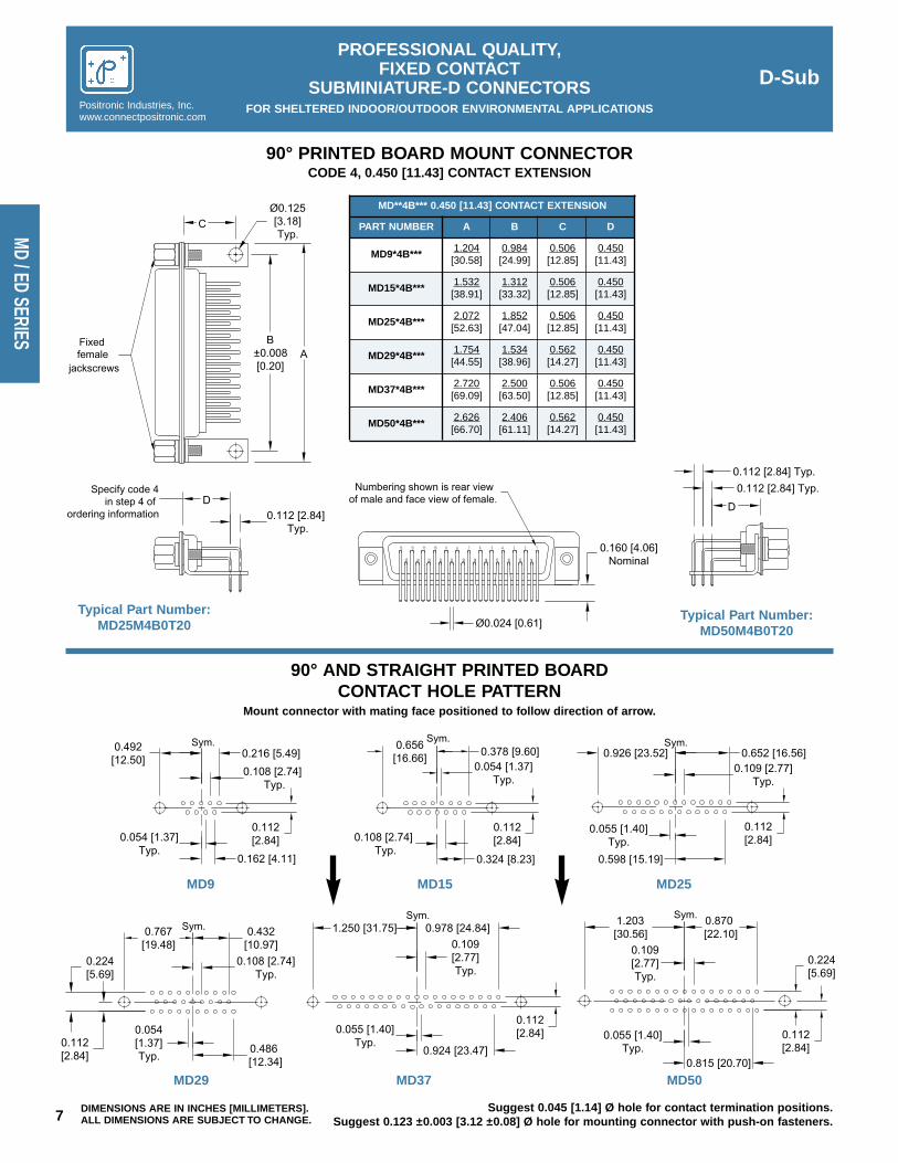
90° PRINTED BOARD MOUNT CONNECTORCODE 4, 0.450 [11.43] CONTACT EXTENSION
90° AND STRAIGHT PRINTED BOARDCONTACT HOLE PATTERN
Mount connector with mating face positioned to follow direction of arrow.
Typical Part Number:MD25M4B0T20
Typical Part Number:MD50M4B0T20
MD**4B*** 0.450 [11.43] CONTACT EXTENSION
MD50*4B***2.626[66.70]
2.406[61.11]
0.562[14.27]
0.450[11.43]
PART NUMBER A B C D
MD9*4B***1.204[30.58]
0.984[24.99]
0.506[12.85]
0.450[11.43]
MD15*4B***1.532[38.91]
1.312[33.32]
0.506[12.85]
0.450[11.43]
MD25*4B***2.072[52.63]
1.852[47.04]
0.506[12.85]
0.450[11.43]
MD29*4B***1.754[44.55]
1.534[38.96]
0.562[14.27]
0.450[11.43]
MD37*4B***2.720[69.09]
2.500[63.50]
0.506[12.85]
0.450[11.43]
MD9 MD15 MD25
MD50MD37MD29
Suggest 0.045 [1.14] Ø hole for contact termination positions.Suggest 0.123 ±0.003 [3.12 ±0.08] Ø hole for mounting connector with push-on fasteners.

0.112 [2.84] Typ.0.112 [2.84] Typ.
D
jackscrews female Fixed B
±0.008[0.20]
A
C
Specify code 44in step 4 of
ordering informationD
2425 23 22
13 12 11 10
21 20 19 18
9 8 67 5
17 15 15 14
4 3 2 1
Numbering shown is rear view of male and face view of female.
Push-on fastenerberyllium copper
0.100 [2.54]Typ.
Ø0.028 [0.71] 0.197 [5.01]Nominal
Specify code 42or 52 in step 4 of
ordering informationD
0.100 [2.54] Typ.for code 42
contacts0.112 [2.84] Typ.
for code 52 contacts
D
713 12 11 10 9 8
2021222325 24
6 5 4 3 2 1
141515171819
Numbering shown is rear view of male and face view of female.
C
AB
±0.008[0.20]jackscrews
female Fixed
Ø0.125[3.18]Typ.
0.064 [1.61] Typ.for code 42 contacts
0.112 [2.84] Typ.for code 52 contacts
0.100 [2.54] Typ.for code 42 contacts
0.112 [2.84] Typ.for code 52 contacts
Ø0.028 [0.71]
0.160 [4.06]Nominal
D-SubPROFESSIONAL QUALITY,
FIXED CONTACTSUBMINIATURE-D CONNECTORS
FOR SHELTERED INDOOR/OUTDOOR ENVIRONMENTAL APPLICATIONS
8DIMENSIONS ARE IN INCHES [MILLIMETERS].ALL DIMENSIONS ARE SUBJECT TO CHANGE.
Positronic Industries, Inc.www.connectpositronic.com
MD /
ED S
ERIE
S
90° PRINTED BOARD MOUNT CONNECTORCODE 42 AND 52, 0.370 [9.40] CONTACT EXTENSION
90° PRINTED BOARD MOUNT CONNECTORCODE 44, 0.370 [9.40] CONTACT EXTENSION
Typical Part Number:ED25M42B0T2X
Typical Part Number:ED25M44BNT2X
Typical Part Number:ED50M52B0T2X
Typical Part Number:ED29M44BNT2X
ED***B*** 0.370 [9.40] CONTACT EXTENSION
ED50**B***2.626[66.70]
2.406[61.11]
0.470[11.94]
0.370[9.40]
PART NUMBER A B C D
ED9**B***1.204[30.58]
0.984[24.99]
0.420[10.67]
0.370[9.40]
ED15**B***1.532[38.91]
1.312[33.32]
0.420[10.67]
0.370[9.40]
ED25**B***2.072[52.63]
1.852[47.04]
0.420[10.67]
0.370[9.40]
ED29**B***1.754[44.55]
1.534[38.96]
0.470[11.94]
0.370[9.40]
ED37**B***2.720[69.09]
2.500[63.50]
0.420[10.67]
0.370[9.40]
ED**44B*** 0.370 [9.40] CONTACT EXTENSION
ED50*44B***2.626[66.70]
2.406[61.11]
0.470[11.94]
0.370[9.40]
PART NUMBER A B C D
ED9*44B***1.204[30.58]
0.984[24.99]
0.420[10.67]
0.370[9.40]
ED15*44B***1.532[38.91]
1.312[33.32]
0.420[10.67]
0.370[9.40]
ED25*44B***2.072[52.63]
1.852[47.04]
0.420[10.67]
0.370[9.40]
ED29*44B***1.754[44.55]
1.534[38.96]
0.470[11.94]
0.370[9.40]
ED37*44B***2.720[69.09]
2.500[63.50]
0.420[10.67]
0.370[9.40]

0.216 [5.49]
0.108 [2.74] Typ.
0.162 [4.11]
0.054 [1.37]Typ.
Sym. 0.656[16.66]
0.378 [9.60]
0.324 [8.23]
0.108 [2.74] Typ.
0.054 [1.37]Typ.
0.926 [23.52] 0.652 [16.56]Sym. Sym.
0.109 [2.77]Typ.
0.598 [15.19]
0.055 [1.40]Typ.
1.250 [31.75] 0.978 [24.84]
0.924 [23.47]
0.055 [1.40]Typ.
0.109[2.77]Typ.
Sym. 1.203[30.56]
0.870 [22.10]
0.109[2.77]Typ.
0.055 [1.40]Typ.
Sym.
0.815 [20.70]
Sym. 0.432[10.97]
0.767[19.48]
0.054[1.37]Typ.
0.486 [12.34]
0.108 [2.74]Typ.
0.492[12.50]
X X X
X
Y
X
Y
X
D-SubPROFESSIONAL QUALITY,
FIXED CONTACTSUBMINIATURE-D CONNECTORS
FOR SHELTERED INDOOR/OUTDOOR ENVIRONMENTAL APPLICATIONSPositronic Industries, Inc.www.connectpositronic.com
9 DIMENSIONS ARE IN INCHES [MILLIMETERS].ALL DIMENSIONS ARE SUBJECT TO CHANGE.
MD / ED SERIES
90° AND STRAIGHT PRINTED BOARDCONTACT HOLE PATTERN
Hole identification shown for male connector, use mirror image for female connector.
For code 42 and 52 contacts, mount connector with mating face positioned to follow direction of arrow.For code 44 contacts, mount connector with mating face positioned to oppose direction of arrow.
ED9 ED15 ED25
ED50ED37ED29
Suggest 0.040 [1.02] Ø hole for contact termination positions.Suggest 0.123 ±0.003 [3.12 ±0.08] Ø hole for mounting connector with push-on fasteners.
CODE NUMBER
X Y
36 0.112[2.84]
0.224[5.69]
42 0.100[2.54]
0.200[5.08]
44 0.100[2.54]
0.200[5.08]
52 0.112[2.84]
0.224[5.69]

STEP 1 - Basic Series
STEP 2 - ED SeriesConnector Variants9, 15, 25, 29, 37, 50
STEP 3 - Connector GenderM – Male F – Female
STEP 4 - Type of Contacts
ED Series
D-SubPROFESSIONAL QUALITY,
FIXED CONTACTSUBMINIATURE-D CONNECTORS
FOR SHELTERED INDOOR/OUTDOOR ENVIRONMENTAL APPLICATIONS
10
Positronic Industries, Inc.www.connectpositronic.com
MD /
ED S
ERIE
S
ORDERING INFORMATION – CODE NUMBERING SYSTEM
STEP
2 – Solder cup.36 – Solder, Straight Printed Board Mount
with 0.236 [5.99] Tail Length.42 – Solder, 90° Printed Board Mount with
0.370 [9.40] Contact Extension.44 – Solder, Inverted 90° Printed Board
Mount with 0.370 [9.40] ContactExtension.
52 – Solder, 90° Printed Board Mount with0.370 [9.40] Contact Extension.
*STEP 6 - Hoods and Push-On Fasteners
*STEP 5 - Mounting StyleRefer to MD Series Step 5
Refer to MD Series Step 7
Refer to MD Series Step 6
*STEP 7 - Locking and PolarizingSystems
STEP 8 - Shell Options0 – Zinc Plated, with
Dichromate Seal.X – Tin Plated.Z – Tin Plated and Dimpled.
STEP 9 - Special OptionsConsult Sales Department
*For additional information on accessorieslisted in steps 5, 6 and 7, see AccessoryCatalog.
**Ferrite inductor is available on contacttypes 36 only.
94
42
5
R7
6
N
7
T2
8
0
1 2 3
ED 25 F
*For additional information on accessories listed insteps 5, 6 and 7, see Accessory Catalog.
**Ferrite inductor is available on contact types 32, 4,59 and 6 only.
0 – None.V3 – Lock Tab, connector front panel mounted.V5 – Lock Tab, connector rear panel mounted.VL – Lock Lever, used with Hoods only.T – Fixed Female Jackscrews.T2 – Fixed Female Jackscrews.T6 – Fixed Male and Female Polarized
Jackscrews.E – Rotating Male Jackscrews.E2 – Rotating Male Screw Locks.E6 – Rotating Male and Female Polarized
Jackscrews.
STEP
STEP 1 - Basic Series
STEP 2 - MD Series Connector Variants9, 15, 25, 29, 37, 50
STEP 3 - Connector GenderM – Male F – Female
STEP 4 - Type of Contacts2 – Solder cup.3 – Solder, Straight Printed Board Mount
with 0.150 [3.81] Tail Length.32 – Solder, Straight Printed Board Mount
with 0.375 [9.52] Tail Length.4 – Solder, 90° Printed Board Mount with
0.450 [11.43] Contact Extension.5 – Solder, 90° Printed Board Mount with
0.283 [7.19] Contact Extension.59 – Solder, 90° Printed Board Mount with
0.545 [13.84] Contact Extension.6 – Wrap Post.
*STEP 7 - Locking and Polarizing Systems
*STEP 6 - Hoods and Push-On Fasteners0 – None.J – Hood, Top Opening, Plastic.L – Hood, Side Opening, Plastic.Y – Hood, Top Opening, Plastic with Rotating Male Jackscrews. Available in size 50
only.Y6 – Hood, Top Opening, Plastic with Rotating Male and Female Polarized Jackscrews.
Available in size 50 only.Z – Hood, Top or Side Opening, Robust and Extended Height, Composite and Plastic
with Rotating Male Jackscrews. Available in size 9, 15, 25, 37, and 50 only.H – Hood, Top Opening, Metal. Available in size 15, 25, 37, and 50 only.G – Hood, EMI/RFI, Metal. Available in size 9, 15, 25, 37, and 50 only.W – Hood, Top or Side Opening, Plastic. Available in size 9, 15, and 25 only.N – Push-on Fastener, for 90° Mounting Brackets.**F – Ferrite inductor.**Q – Ferrite inductor for use with Push-on Fastener and 90° Mounting Brackets.
STEP 8 - Shell Options0 – Zinc Plated, with Dichromate Seal.X – Tin Plated.Z – Tin Plated and Dimpled.
*STEP 5 - Mounting Style0 – Mounting Hole, 0.120 [3.05] Ø.02 – Mounting Hole, 0.154 [3.91] Ø.B – Bracket, Mounting, 90° Metal.B3 – Bracket, Mounting, 90° Metal with Cross Bar.B7 – Bracket, Mounting, 90° Plastic.B8 – Bracket, Mounting, 90° Plastic with
Cross Bar.F – Float Mounts, Universal.P – Threaded Post, Brass, 0.225 [5.71] Length.P2 – Threaded Post, Nylon, 0.225 [5.71] Length.R – Bracket, Mounting, 90° Metal, Swaged to
Connector with 4-40 Thread Fixed FemaleJackscrews.
R2 – Bracket, Mounting, 90° Metal, Swaged toConnector with 4-40 Thread Fixed FemaleJackscrews with Cross Bar.
R3 – Bracket, Mounting, 90° Metal, Swaged toConnector with 0.120 [3.05] Ø MountingHole.
R4 – Bracket, Mounting, 90° Metal, Swaged toConnector with 4-40 Threads.
R5 – Bracket, Mounting, 90° Metal, Swaged toConnector with 4-40 Locknut.
R6 – Bracket, Mounting, 90° Metal, Swaged toConnector with 0.120 [3.05] Ø MountingHole with Cross Bar.
R7 – Bracket, Mounting, 90° Metal, Swaged toConnector with 4-40 Threads with Cross Bar.
R8 – Bracket, Mounting, 90° Metal, Swaged toConnector with 4-40 Locknut with Cross Bar.
S – Swaged Spacer, 4-40 Threads, 0.225 [5.71]Length.
S2 – Swaged Spacer, 4-40 Threads, 0.125 [3.18]Length.
S5 – Swaged Locknut, 4-40 Threads.S6 – Swaged Spacer with Push-on Fastener,
4-40 Threads, 0.225 [5.71] Length.S7 – Swaged Spacer with Push-on Fastener for
use with Ferrite Inductor, 4-40 Threads,0.375 [9.53] Length.
STEP 9 - Special OptionsConsult Sales Department.
MD Series
1 2 3
MD 25 F
4
59
5
R7
6
N
7
T6
8
X
9
MELO-D SERIES
EURO-D SERIES
Specify CompleteConnector
By FollowingSteps 1 through 9
Insert “0” When Step Is Not Used

Size 20 Contacts,Removable
Professional QualityConnectors
IEC Publication 807-3Performance Level Two
U.L. Recognized CSA RecognizedFile #E49351 File #LR54219
TelecommunicationU.L. File #14098
Soli-D Series connectors are professional quality connectors recom-mended for use in sheltered, non-corrosive indoor or outdoor environ-ments having normal ventilation, but without temperature or humiditycontrols. This crimp removable contact connector will meet thePerformance Level Two requirements of IEC 807-3.
Soli-D Series connectors utilize precision machined contacts withclosed barrel, crimp terminations. The female contact features theRobi-Contact open entry design. Other contact terminations such assolder cup and printed board terminations are also available. Theremovable contact feature provides for rapid assembly and permitscontact repairs on wiring changes.
Five standard contact variants are offered in arrangements of 9, 15,25, 37 and 50 contacts. Soli-D Series connectors are mateable andcompatible with all D-Subminiature connectors conforming to IEC 807-2, IEC 807-3 and MIL-DTL-24308.
A wide assortment of cable support hoods and locking systems isavailable from stock.
Soli-D Series connectors conform to EIA RS 232 and RS 449, andCCITT X.24 interface connection requirements.
SOLI-D SERIES TECHNICAL CHARACTERISTICSMATERIALS AND FINISHES:Insulator: Glass filled nylon resin, UL 94V-0, black
color.
Contacts: Male contacts – precision machinedbrass. Female contacts – precisionmachined high tensile phosphorbronze.
Contact Plating: Professional performance – gold flashover nickel plate. Other finishes availableupon request.
Shells: Steel with tin plate; zinc plate withdichromate seal. Other materials andfinishes available upon request.
Mounting Spacers: Nylon plastic, or brass, zinc plate withdichromate seal.
Push-On Fasteners: Phosphor bronze with tin plate.
Jackscrew Systems: Steel with zinc plate and dichromateseal, or clear zinc plate.
Vibration Lock Systems: Slide lock and lock tabs, steel with nick-el plate.
Hoods: Thermoplastic UL 94V-0. Composite,brass or steel with zinc plate anddichromate seal.
ELECTRICAL CHARACTERISTICS:Contact Current Rating: 7.5 amperes nominal.
Initial Contact Resistance: 0.008 ohms maximum.
Proof Voltage: 1000 V r.m.s.
Insulator Resistance: 5 G ohms.
Clearance and CreepageDistance [minimum]: 0.039 inch [1.0mm].
Working Voltage: 300 V r.m.s.
CLIMATIC CHARACTERISTICS:Temperature Range: -55°C to +125°C.
Damp Heat, Steady State: 10 days.
MECHANICAL CHARACTERISTICS:Removable Contacts: Insert contact to rear face of insulator and
release from rear face of insulator. Size 20contacts, male – 0.040 inch [1.02mm]diameter; female – Robi-D contact openentry design.
Contact RetentionIn Insulator: 6 lbs. [27 N].
Contact Terminations: Closed barrel crimp, wire sizes 18 AWG[1.0mm2] through 32 AWG [0.03mm2].Also, solder cup and straight printedboard mount terminations.
Shells: Male shells may be dimpled for EMI/ESDground paths.
Polarization: Trapezoidally shaped shells and polar-ized jackscrews.
Printed Board Mount: Rapid installation push-on fasteners.
Locking Systems: Jackscrews and vibration locking sys-tems.
Mechanical Operations: 500 operations minimum per IEC 512-5.
D-SubPROFESSIONAL QUALITY,
REMOVABLE CONTACTSUBMINIATURE-D CONNECTORS
FOR SHELTERED INDOOR/OUTDOOR ENVIRONMENTAL APPLICATIONSPositronic Industries, Inc.www.connectpositronic.com
11 DIMENSIONS ARE IN INCHES [MILLIMETERS].ALL DIMENSIONS ARE SUBJECT TO CHANGE.
SD SERIES

12DIMENSIONS ARE IN INCHES [MILLIMETERS].ALL DIMENSIONS ARE SUBJECT TO CHANGE.
D-SubPROFESSIONAL QUALITY,
REMOVABLE CONTACTSUBMINIATURE-D CONNECTORS
FOR SHELTERED INDOOR/OUTDOOR ENVIRONMENTAL APPLICATIONS Positronic Industries, Inc.www.connectpositronic.com
SD S
ERIE
S
222120
31 2
2423 26 2725 3028 29 32 3331
654 87 1211109 1413
3634 35 37
171615 1918
383534 3736 39 40 4341 42
5
18 20 2119
21 43
242322 272625
76 1098
45 4644 4947 48 50
333028 29 3231
131211 161514 17
9876
1 542 3
15141211109 13
321 87654
14
1 2
2524232221201817 191615
876543 1312109 11
CONTACT VARIANTSFACE VIEW OF MALE OR REAR VIEW OF FEMALE
SD 9 SD 15 SD 25
SD 37 SD 50
STANDARD SHELL ASSEMBLY
CONNECTORVARIANT SIZES
A±0.015[0.38]
B±0.005[0.13]
B1±0.005[0.13]
C±0.005[0.13]
D±0.005[0.13]
D1±0.005[0.13]
E±0.015[0.38]
G±0.010[0.25]
H±0.010[0.25]
K±0.005[0.13]
M±0.010[0.25]
SD 9 M1.213[30.81]
0.666[16.92]
0.984[24.99]
0.329[8.36]
0.494[12.55]
0.759[19.28]
0.422[10.72]
0.233[5.92]
0.422[10.72]
SD 9 F1.213[30.81]
0.643[16.33]
0.984[24.99]
0.311[7.90]
0.494[12.55]
0.759[19.28]
0.422[10.72]
0.243[6.17]
0.429[10.90]
SD 15 M1.541[39.14]
0.994[25.25]
1.312[33.32]
0.329[8.36]
0.494[12.55]
1.083[27.51]
0.422[10.72]
0.233[5.92]
0.422[10.72]
SD 15 F1.541[39.14]
0.971[24.66]
1.312[33.32]
0.311[7.90]
0.494[12.55]
1.083[27.51]
0.422[10.72]
0.243[6.17]
0.429[10.90]
SD 25 M2.088[53.04]
1.534[38.96]
1.852[47.04]
0.329[8.36]
0.494[12.55]
1.625[41.28]
0.422[10.72]
0.230[5.84]
0.426[10.82]
SD 25 F2.088[53.04]
1.511[38.38]
1.852[47.04]
0.311[7.90]
0.494[12.55]
1.625[41.28]
0.422[10.72]
0.243[6.17]
0.429[10.90]
SD 37 M2.729[69.32]
2.182[55.42]
2.500[63.50]
0.329[8.36]
0.494[12.55]
2.272[57.71]
0.422[10.72]
0.230[5.84]
0.426[10.82]
SD 37 F2.729[69.32]
2.159[54.84]
2.500[63.50]
0.311[7.90]
0.494[12.55]
2.272[57.71]
0.422[10.72]
0.243[6.17]
0.429[10.90]
SD 50 M2.635[66.93]
2.079[52.81]
2.406[61.11]
0.441[11.20]
0.605[15.37]
2.178[55.32]
0.534[13.56]
0.230[5.84]
0.426[10.82]
SD 50 F2.635[66.93]
2.064[52.43]
2.406[61.11]
0.423[10.74]
0.605[15.37]
2.178[55.32]
0.534[13.56]
0.243[6.17]
0.429[10.90]
C
A
E
BB1
DD1
KM
G
H
0.437 [11.10]Max.
10° Typ.
Ø0.120±0.005 [Ø3.05±0.13] Mounting hole, two places
0.036±0.008[0.91±0.20]
two places (02 option)Ø0.154 [3.91] Mounting hole,
Ø0.120±0.005 [Ø3.05±0.13] Mounting hole, two places for stainless steel shell (0 option) [
Mounting hole, two placesTotal diametral float0.032 [0.81] Ø0.086+0.005
-0.000
0.120±0.010 [3.05±0.25]
+0.13-0.00Ø2.18 ]
0.050±0.010[1.27±0.25]
OPTIONAL SHELL ASSEMBLY WITH UNIVERSAL FLOAT MOUNTS [F]OPTIONAL SHELL ASSEMBLY [0, 02]

0.927 [23.55]Ø0.086[2.18]
0.915 [23.25]
0.170 [4.32]
Ø0.055[1.40] 0.170
[4.32]
Ø0.040 [1.02]
Ø0.086[2.18]
Ø0.055[1.40]
øC
øB
A
Ø0.040 [1.02]
øB
øC
0.170 [4.32]
A
0.170 [4.32]
D-SubPROFESSIONAL QUALITY,
REMOVABLE CONTACTSUBMINIATURE-D CONNECTORS
FOR SHELTERED INDOOR/OUTDOOR ENVIRONMENTAL APPLICATIONSPositronic Industries, Inc.www.connectpositronic.com
13 DIMENSIONS ARE IN INCHES [MILLIMETERS].ALL DIMENSIONS ARE SUBJECT TO CHANGE.
SD SERIES
CRIMP CONTACTS
CLOSED CRIMP BARREL
FEMALE CONTACT
FEMALE CONTACT18 AWG [1.0 mm2] max.
MALE CONTACT18 AWG [1.0 mm2] max.
MALE CONTACT
PART NUMBER WIRE SIZEAWG/[mm2]
A ØB ØC
FC7520D20 / 22 / 24
[0.5/0.3/0.25]0.612[15.54]
0.045[1.14]
0.066[1.68]
FC7526D26 / 28 / 30
[0.12/0.08/0.05]0.612[15.54]
0.026[0.66]
0.066[1.68]
PART NUMBER WIRE SIZEAWG/[mm2]
A ØB ØC
MC7520D20 / 22 / 24
[0.5/0.3/0.25]0.618[15.70]
0.045[1.14]
0.066[1.68]
MC7526D26 / 28 / 30
[0.12/0.08/0.05]0.618[15.70]
0.026[0.66]
0.066[1.68]
Note: *C75**D contacts can not be used in the RD series.Crimp contacts must be ordered separately.
Additional plating options available by adding suffix to part numberadd -14 for 0.000030 [0.76 microns] gold over nickel Example: FC7520D-14 or MC7518D-14
MC7518DFC7518D
Material – Phosphor bronze.Plating – Gold flash over nickel.
Material – Brass.Plating – Gold flash over nickel.
REELS FOR AUTOMATIC FEED PNEUMATIC CRIMP TOOLS
Contacts may be supplied in plastic carriers, packaged in reels holding 2,000 con-tacts for use with the automatic feed pneumatic crimp tools, catalog part number9550-1. The same type carrier is used for both male and female contacts.
All male and female crimp contacts can be ordered in reels by adding letter “R” afterthe contact part number, such as MC7526DR for a male contact and FC7520DR fora female contact.
Enlarged section of plastic contact carriers

14DIMENSIONS ARE IN INCHES [MILLIMETERS].ALL DIMENSIONS ARE SUBJECT TO CHANGE.
D-SubPROFESSIONAL QUALITY,
REMOVABLE CONTACTSUBMINIATURE-D CONNECTORS
FOR SHELTERED INDOOR/OUTDOOR ENVIRONMENTAL APPLICATIONS Positronic Industries, Inc.www.connectpositronic.com
SD S
ERIE
S
A A
øDøDØ0.040 [1.02]
FEMALE CONTACT MALE CONTACT
STRAIGHT PRINTED BOARD MOUNT CONTACTS
Straight printed board mount contacts are supplied in connector.
CODENUMBER
L ØD A
30.125[3.18]
0.024[0.61]
0.772[19.61]
320.188[4.78]
0.024[0.61]
0.835[21.21]
CODENUMBER
L ØD A
30.125[3.18]
0.024[0.61]
0.768[19.51]
320.188[4.78]
0.024[0.61]
0.831[21.11]
L Nominal
Fixed female jackscrews
Swaged spacer withpush-on fastenerphosphor bronze.
0.437 [11.10]
For straight printed board mount contacts specify code no. in step 4 of ordering information.
Typical Part Number:SD37F3S60T2X
Material – Phosphor bronze or brass.Plating – Gold flash over nickel.

0.216 [5.49]
0.108 [2.74] Typ.
0.162 [4.11]
0.054 [1.37]Typ.
Sym. 0.656[16.66]
0.378 [9.60]
0.324 [8.23]
0.108 [2.74] Typ.
0.054 [1.37]Typ.
0.926 [23.52] 0.652 [16.56]Sym. Sym.
0.109 [2.77]Typ.
0.598 [15.19]
0.055 [1.37]Typ.
1.250 [31.75] 0.978 [24.84]
0.924 [23.47]
0.055 [1.40]Typ.
0.109[2.77]Typ.
Sym. 1.203[30.56]
0.870[22.10]
0.109 [2.77]Typ.
0.055 [1.40]Typ.
Sym.
0.815 [21.70]
0.492[12.50]
0.112[2.84]
0.112[2.84]
0.112[2.84]
0.112[2.84]
0.224[5.69]
0.112[2.84]
D-SubPROFESSIONAL QUALITY,
REMOVABLE CONTACTSUBMINIATURE-D CONNECTORS
FOR SHELTERED INDOOR/OUTDOOR ENVIRONMENTAL APPLICATIONSPositronic Industries, Inc.www.connectpositronic.com
15 DIMENSIONS ARE IN INCHES [MILLIMETERS].ALL DIMENSIONS ARE SUBJECT TO CHANGE.
SD SERIES
STRAIGHT PRINTED BOARD CONTACT HOLE PATTERN
Hole identification shown for male connector, use mirror image for female connector.
SD9 SD15 SD25
SD50SD37
Suggest 0.045 [1.14] Ø hole for contact termination positions.Suggest 0.123 ±0.003 [3.12 ±0.08] Ø hole for mounting connector with push-on fasteners.
SD25F3S600XSD37M3S600Z

16DIMENSIONS ARE IN INCHES [MILLIMETERS].ALL DIMENSIONS ARE SUBJECT TO CHANGE.
D-SubPROFESSIONAL QUALITY,
REMOVABLE CONTACTSUBMINIATURE-D CONNECTORS
FOR SHELTERED INDOOR/OUTDOOR ENVIRONMENTAL APPLICATIONS Positronic Industries, Inc.www.connectpositronic.com
SD S
ERIE
S
CRIMPING INFORMATION FOR RD AND SD SERIES CRIMP CONTACTS
USE INDICATED POSITRONIC TOOLS FOR BEST RESULTS
Step 1: Strip wire to indicated length.
Step 2: Crimp wire to contact.For Hand Crimp Tool: - Place contact into crimping tool.
- Insert wire into contact.- Center contact by slowly closing the
crimping tool until the crimp indentersmake contact with the crimp barrel.
- Complete the cycle of the crimping tool inone smooth motion.
- Remove the crimped contact.
Take Care Not To: - Damage or remove strands.- Untwist or overtwist strands.- Leave insulation particles on strands.- Damage insulation.
For Automatic Feed Pneumatic Crimp Tool: - Insert the wire into the contact, positioned in thecrimp tool by the plastic carrier.
- Depress the activating device of the crimpingtool to start the crimping cycle.
- Remove the crimped contact.
0.160[4.06]
Insulation
Stranded Wire
Strands damagedor removed bystripping tool.
Insulation cutincorrectly.
Strands overtwisted.
Particles of insulation on thestripped part ofthe wire.
Wire insulation damaged.
Strands untwisted.
Examples of Stripping Faults
Correctly Stripped Wire
±0.020 [0.51]

D-SubPROFESSIONAL QUALITY,
REMOVABLE CONTACTSUBMINIATURE-D CONNECTORS
FOR SHELTERED INDOOR/OUTDOOR ENVIRONMENTAL APPLICATIONSPositronic Industries, Inc.www.connectpositronic.com
17 DIMENSIONS ARE IN INCHES [MILLIMETERS].ALL DIMENSIONS ARE SUBJECT TO CHANGE.
SD SERIES
CRIMPING INFORMATION FOR RD AND SD CRIMP CONTACTS
Conductor tensile strength values are derived using silver-tin plated copper wires.Values may change depending upon what type of wire is used.
Wire Insulation, Typical
Crimp to meet recommendedtensile strength.
Stripped wires compressedfor improved conduction.
8 Crimp Indents
Crimp indents too closeto inspection hole.
Strands not visiblethrough inspection hole.Strands visible beyond
insulation support.
Stripped part ofthe wire too long.
Stripped part ofthe wire too short.
Crimp indents incorrectly located.
Step 3: Inspect the crimp.For All Tools: - Strands to be visible through the inspection hole.
- Strands not to be visible beyond the insulation support.- Crimped contact to meet recommended conductor tensile
force shown in chart.- Check for peeled gold and bent contacts.
Correctly Crimped Contact
Cross Section of Correctly Crimped Contact
Examples of Crimping Faults
Positronic RecommendedConductor Tensile Strength
Positronic recommended tools for SD series contacts.For more information see contact crimp tools and accessories page.
CRIMP TOOLSPOSITIONERS FORFC7520D, FC7526D,MC7520D, MC7526D
POSITIONERS FORFC7518D, MC7518D,FC6018D, MC6018D
9507, HAND CRIMP TOOL 9502-10 9502-11
9550-1, AUTOMATIC FEEDPNEUMATIC CRIMP TOOL
Supplied in reels Not Available
WIRE SIZEAWG/[mm2]
AXIAL LOADPOUNDS/[N]
20 [0.5]
20 [89]
24 [0.25]
8 [36]
22 [0.3]
12 [53]
26 [0.12]
5 [22]
18 [1.0]
28 [125]
28 [0.08]
3 [13]
30 [0.05]
1.5 [6.7]

18DIMENSIONS ARE IN INCHES [MILLIMETERS].ALL DIMENSIONS ARE SUBJECT TO CHANGE.
D-SubPROFESSIONAL QUALITY,
REMOVABLE CONTACTSUBMINIATURE-D CONNECTORS
FOR SHELTERED INDOOR/OUTDOOR ENVIRONMENTAL APPLICATIONS Positronic Industries, Inc.www.connectpositronic.com
SD S
ERIE
S
AUTOMATIC FEEDCRIMP TOOL,
PNEUMATICALLY ACTUATEDPart No. 9550-1
MINIATURE STEP ADJUSTABLE TOOL(M22520/2-01)Part No. 9507
INSERTION/REMOVAL TOOL(M81969/1-02)
This fast cycling automatic feed crimp tool produces an 8indent crimp on wire sizes 20 AWG [0.5mm2] through 32AWG [0.03mm2]. Soli-D Series contacts must be ordered onreels.
To order, specify part number 9550-1. Foot control valve issupplied as a standard accessory.
This miniature step adjustable hand crimping tool producesan 8 indent crimp configuration and will crimp wire sizes 18AWG [1.0mm2] through 32 AWG [0.03mm2].
To crimp wire size 18 AWG [1.0mm2], order contact position-er 9502-11. To crimp wire size 20 AWG [0.5mm2] through 32AWG [0.03mm2], order contact positioner 9502-10. Eachpositioner is equipped with a data plate which gives thecorrect crimp-depth setting for each wire size, and must beused with 9507 tool frame for best results when crimpingSoli-D Series contacts.
One end of this tool is used to insert contacts into Soli-DSeries connectors. The other end is used to extract contacts.This is accomplished by sliding the extraction tip down thewire into the connector until it bottoms against the contact. Aslight rotation while pushing will release the contacts, whichare then extracted by simultaneously pulling on the wire.

D-SubPROFESSIONAL QUALITY,
REMOVABLE CONTACTSUBMINIATURE-D CONNECTORS
FOR SHELTERED INDOOR/OUTDOOR ENVIRONMENTAL APPLICATIONSPositronic Industries, Inc.www.connectpositronic.com
19 DIMENSIONS ARE IN INCHES [MILLIMETERS].ALL DIMENSIONS ARE SUBJECT TO CHANGE.
SD SERIES*For additional information on accessories listed insteps 5, 6 and 7, see Accessory Catalog.
1 2 3 4 5 6
SD 25 F 3 S6 0 T6
7
X
8 9STEP
STEP 1 - Basic SeriesSD Series
STEP 2 - SD Series Connector Variants9, 15, 25, 37, 50
STEP 3 - Connector GenderM - Male F - Female
STEP 4 - Type of Contacts0 - Order Contacts separately.1 - Crimp, 20 AWG–24 AWG [0.5mm2–0.25mm2].12 - Crimp, 26 AWG–30 AWG [0.12mm2–0.05mm2 ].3 - Solder, Straight Printed Board Mount with 0.125 [3.18] Tail Length.32 - Solder, Straight Printed Board Mount with 0.188 [4.78] Tail Length.
*STEP 7 - Locking and Polarizing Systems0 - None.V3 - Lock Tab, connector front panel mounted.V5 - Lock Tab, connector rear panel mounted.VL - Lock Lever, used with Hoods Only.T - Fixed Female Jackscrews.T2 - Fixed Female Jackscrews.T6 - Fixed Male and Female Polarized Jackscrews.E - Rotating Male Jackscrews.E2 - Rotating Male Screw Locks.E6 - Rotating Male and Female Polarized Jackscrews.
*STEP 6 - Hoods0 - None.J - Hood, Top Opening, Plastic.L - Hood, Side Opening, Plastic.Y - Hood, Side Opening, Plastic with Rotating Male
Jackscrews. Available in size 50 only.Y6 - Hood, Top Opening, Plastic with Rotating Male
and Female Polarized Jackscrews. Available insize 50 only.
Z - Hood, Top or Side Opening, Robust and Extended Height, Composite and Plastic with Rotating MaleJackscrews.
H - Hood, Top Opening, Metal. Available in size 15, 25, 37, and 50 only.
G - Hood, EMI/RFI, Metal.W - Hood, Top or Side Opening, Plastic. Available in
size 9,15, and 25 only.
STEP 8 - Shell Options0 - Zinc Plated with Dichromate Seal.X - Tin Plated.Z - Tin Plated and Dimpled.
*STEP 5 - Mounting Style0 - Mounting Hole, 0.120 [3.05] Ø.02 - Mounting Hole, 0.154 [3.91] Ø.F - Float Mounts, Universal.P - Threaded Post, Brass, 0.437 [11.10] Length.P2 - Threaded Post, Nylon, 0.437 [11.10] Length.S - Swaged Spacer, 4-40 Threads, 0.437 [11.10] Length.S2 - Swaged Spacer, 4-40 Threads, 0.125 [3.18] Length.S5 - Swaged Locknut, 4-40 Threads.S6 - Swaged Spacer with Push-on Fastener, 4-40 Threads,
0.437 [11.10] Length.
STEP 9 - Special OptionsConsult Sales Department.
Specify Complete Connector By Following Steps 1 Through 9.Insert “0” When Step Is Not Used.
ORDERING INFORMATION - CODE NUMBERING SYSTEM

Size 22 Contacts,Removable Crimp andPrinted Board Mount
Military/Industrial Quality Connectors
MIL-DTL-24308 and MIL-C-39029
U.L. Recognized CSA RecognizedFile #E49351 File #LR54219
TelecommunicationU.L. File #14098
Densi-D Series connectors are Military/Industrial quality, high densi-ty rectangular connectors designed for use in sheltered, mildly corro-sive environments having a wide range of temperature, pressure andhumidity changes. These crimp removable contact connectors arequalified to MIL-DTL-24308 and MIL-C-39029.
Densi-D Series connectors utilize precision machined contacts withclosed barrel crimp terminations, solder cup terminations, straight and90° printed board mount. All female contacts are of closed entry
design, featuring a fluted stainless steel shroud.Six standard contact variants are offered in arrangements of 15, 26,
44, 62, 78 and 104 contacts. Densi-D Series connectors are mateableand compatible with other high density D-Subminiature connectorsconforming to MIL-DTL-24308.
A wide assortment of mounting spacers, cable support hoods andlocking systems is available from stock.
DENSI-D SERIES TECHNICAL CHARACTERISTICSMATERIALS AND FINISHES:Insulators: Glass filled polyester per MIL-M-24519,
UL 94V-0, blue color.
Contacts: Male contacts – precision machinedhigh tensile copper alloy. Female con-tacts – precision machined high tensilecopper alloy with stainless steel shroud.
Contact Plating: Military performance – 0.000050 inch[1.27 microns] gold over copper plate.Industrial performance – gold flash overnickel plate. Other finishes available uponrequest.
Shells: Steel with tin plate; zinc and cadmiumplate with dichromate seal, stainlesssteel, passivated. Other materials and fin-ishes available upon request.
Mounting Spacers: Nylon plastic and brass; zinc plate withdichromate seal.
Push-On Fastener: Phosphor bronze or beryllium copper with tinplate.
Vibration Lock Systems: Slide lock and lock tabs, steel with nick-el plate.
Jackscrew Systems: Steel with zinc plate and dichromateseal, or clear zinc plate.
Hoods: Thermoplastic UL 94V-0. Composite,brass or steel with zinc plate anddichromate seal.
ELECTRICAL CHARACTERISTICS:Contact Current Rating: 5 amperes nominal.
Initial Contact Resistance: 0.005 ohms maximum.
Proof Voltage: 1000 V r.m.s.
Insulator Resistance: 5 G ohms.
Clearance and CreepageDistance [minimum]: 0.042 inch [1.06mm].
Working Voltage: 300 V r.m.s.
CLIMATIC CHARACTERISTICS:Temperature Range: -55°C to +125°C.
Damp Heat, Steady State: 21 days.
MECHANICAL CHARACTERISTICS:Removable Contacts: Insert contact to rear face of insulator and
release from rear face of insulator. Size 22contacts, male – 0.030 inch [0.76mm]diameter; female – closed entry designwith stainless steel shroud.
Contact RetentionIn Insulator: 9 lbs. [40 N].
Contact Terminations: Closed barrel crimp, wire sizes 22 AWG[0.3mm2] through 30 AWG [0.05mm2] perIEC 352-2.90° Printed Board Mount contact termi-nations.
Shells: Male shells may be dimpled for EMI/ESDground paths.
Polarization: Trapezoidally shaped shells and polar-ized jackscrews.
Mounting To Angle Brackets: Jackscrews and riveted fasteners with
0.120 inch [3.05mm] clearance hole,and threaded riveted fasteners with 4-40threads and nylon lock inserts.
Mounting To Printed Board: Rapid installation push-on fasteners and
mounting posts.
Locking Systems: Jackscrews and vibration locking sys-tems.
Mechanical Operations: 1000 operations minimum per IEC 512-5.
20DIMENSIONS ARE IN INCHES [MILLIMETERS].ALL DIMENSIONS ARE SUBJECT TO CHANGE.
D-SubMILITARY QUALITY,
REMOVABLE CONTACT, HIGH DENSITY SUBMINIATURE-D CONNECTORS
FOR MILITARY AND SEVERE INDUSTRIAL ENVIRONMENTAL APPLICATIONS Positronic Industries, Inc.www.connectpositronic.com
DD S
ERIE
S

KM
G
H
0.375 [9.53]Max.
10° Typ.
Ø0.120±0.005 [Ø3.05±0.13] Mounting hole, two places
0.036±0.008[0.91±0.020]
0.050±0.010[1.27±0.25]
E
B1 B
A
C
D1 D
two places (02 option)Ø0.154 [3.91] Mounting hole,
Ø0.120±0.005 [Ø3.05±0.13] Mounting hole, two places for stainless steel shell (0 option)
[Mounting hole, two places
Total diametral float0.032 [0.81] Ø0.086+0.005
-0.000
0.120±0.010 [3.08±0.25]
+0.13-0.00Ø2.18 ]
OPTIONAL SHELL ASSEMBLY WITH UNIVERSAL FLOAT MOUNTS [F]OPTIONAL SHELL ASSEMBLY [0, 02]
1
43
22 21
62
42
1
21
60
40
20
59
39
78
22
6443
85
1
42
84
63
104
21
D-SubMILITARY QUALITY,
REMOVABLE CONTACT, HIGH DENSITY SUBMINIATURE-D CONNECTORS
FOR MILITARY AND SEVERE INDUSTRIAL ENVIRONMENTAL APPLICATIONSPositronic Industries, Inc.www.connectpositronic.com
21 DIMENSIONS ARE IN INCHES [MILLIMETERS].ALL DIMENSIONS ARE SUBJECT TO CHANGE.
DD SERIES
CONNECTORVARIANT SIZES
A±0.015[0.38]
B±0.005[0.13]
B1±0.005[0.13]
C±0.005[0.13]
D±0.005[0.13]
D1±0.005[0.13]
E±0.015[0.38]
G±0.010[0.25]
H±0.010[0.25]
K±0.005[0.13]
M±0.010[0.25]
DD 15 M1.213[30.81]
0.666[16.92]
0.984[24.99]
0.329[8.36]
0.494[12.55]
0.759[19.28]
0.422[10.72]
0.233[5.92]
0.422[10.72]
DD 15 F1.213[30.81]
0.643[16.33]
0.984[24.99]
0.311[7.90]
0.494[12.55]
0.759[19.28]
0.422[10.72]
0.243[6.17]
0.429[10.90]
DD 26 M1.541[39.14]
0.994[25.25]
1.312[33.32]
0.329[8.36]
0.494[12.55]
1.083[27.51]
0.422[10.72]
0.233[5.92]
0.422[10.72]
DD 26 F1.541[39.14]
0.971[24.66]
1.312[33.32]
0.311[7.90]
0.494[12.55]
1.083[27.51]
0.422[10.72]
0.243[6.17]
0.429[10.90]
DD 44 M2.088[53.04]
1.534[38.96]
1.852[47.04]
0.329[8.36]
0.494[12.55]
1.625[41.28]
0.422[10.72]
0.230[5.84]
0.426[10.82]
DD 44 F2.088[53.04]
1.511[38.38]
1.852[47.04]
0.311[7.90]
0.494[12.55]
1.625[41.28]
0.422[10.72]
0.243[6.17]
0.429[10.90]
DD 62 M2.729[69.32]
2.182[55.42]
2.500[63.50]
0.329[8.36]
0.494[12.55]
2.272[57.71]
0.422[10.72]
0.230[5.84]
0.426[10.82]
DD 62 F2.729[69.32]
2.159[54.84]
2.500[63.50]
0.311[7.90]
0.494[12.55]
2.272[57.71]
0.422[10.72]
0.243[6.17]
0.429[10.90]
DD 78 M2.635[66.93]
2.079[52.81]
2.406[61.11]
0.441[11.20]
0.605[15.37]
2.178[55.32]
0.534[13.56]
0.230[5.84]
0.426[10.82]
DD 78 F2.635[66.93]
2.064[52.43]
2.406[61.11]
0.423[10.74]
0.605[15.37]
2.178[55.32]
0.534[13.56]
0.243[6.17]
0.429[10.90]
DD 104 M2.729[69.32]
2.212[56.18]
2.500[63.50]
0.503[12.78]
0.668[16.97]
2.302[58.47]
0.596[15.14]
0.230[5.84]
0.426[10.82]
DD 104 F2.729[69.32]
2.189[55.60]
2.500[63.50]
0.485[12.32]
0.668[16.97]
2.302[58.47]
0.596[15.14]
0.243[6.17]
0.429[10.90]
106
11 15
1 5
3031
18
2619 44
101 9
151
16
CONTACT VARIANTS
FACE VIEW OF MALE OR REAR VIEW OF FEMALE
DD 15 DD 26 DD 44
DD 104DD 78DD 62
STANDARD SHELL ASSEMBLY

0.518 [13.16]Ø0.047[1.19]
0.150[3.81]
Ø0.035 [0.89]
0.531 [13.49] Ø0.047[1.19]
0.150[3.81]
Ø0.035 [0.89]
Ø0.030[0.76]Stainless Steel
Shroud
Material - Phosphor bronze.Plating - Gold flash over nickel.
Material - Brass.Plating - Gold flash over nickel.
Solder contacts may be supplied kitted with connector or ordered separately.
Enlarged section of plastic contact carriers
SOLDER CUP CONTACTSFEMALE CONTACT
“CLOSED ENTRY” DESIGNMALE CONTACT
Part Number: MS8022DPart Number: FS8022D
REELS FOR AUTOMATIC FEED PNEUMATIC CRIMP TOOLS
Contacts may be supplied in plastic carriers, packaged inreels holding 2,000 contacts for use with the automatic feedpneumatic crimp tools, catalog part number 9550-1. Thesame type carrier is used for both male and female contacts.
All male and female crimp contacts can be ordered in reelsby adding letter “R” after the contact part number, such asMC8022DR for a male contact and FC8022DR for a femalecontact.
AøC
A
øC
øB 0.150 [3.81]
Ø0.030[0.76] øB
*Color Code
Stainless Steel Shroud
*Color Code
0.150 [3.81]
22DIMENSIONS ARE IN INCHES [MILLIMETERS].ALL DIMENSIONS ARE SUBJECT TO CHANGE.
D-SubMILITARY QUALITY,
REMOVABLE CONTACT, HIGH DENSITY SUBMINIATURE-D CONNECTORS
FOR MILITARY AND SEVERE INDUSTRIAL ENVIRONMENTAL APPLICATIONS Positronic Industries, Inc.www.connectpositronic.com
DD S
ERIE
S
CRIMP CONTACTSCLOSED CRIMP BARREL
FEMALE CONTACT “CLOSED ENTRY” DESIGN
MALE CONTACT
Crimp contacts may be supplied kitted with connector or ordered separately.
PART NUMBER WIRE SIZEAWG/[mm2]
A ØB ØC
FC8022D22 / 24 / 26 / 28 / 30
[0.3/0.25/0.12/0.08/0.05]0.518[13.16]
0.035[0.89]
0.047[1.19]
*M39029/57-354 22 / 24 / 26 / 28
[0.3/0.25/0.12/0.08]0.518[13.16]
0.035[0.89]
0.047[1.19]
PART NUMBER WIRE SIZEAWG/[mm2]
A ØB ØC
MC8022D22 / 24 / 26 / 28 / 30
[0.3/0.25/0.12/0.08/0.05]0.531[13.49]
0.035[0.89]
0.047[1.19]
*M39029/58-360 22 / 24 / 26 / 28
[0.3/0.25/0.12/0.08]0.531[13.49]
0.035[0.89]
0.047[1.19]
Material - Brass.Plating - Gold flash over nickel or 0.000050 inch [1.27µ] gold
over copper for military specification contacts.
*Color Code - ORANGE/BLUE/BLACK for military specification contacts.
Material - Leaded nickel copper.Plating - Gold flash over nickel or 0.000050 inch [1.27µ] gold
over copper for military specification contacts.
*Color Code - ORANGE/GREEN/YELLOW for militaryspecification contacts.
For contact crimp tool information see page 28.
Additional plating options available by adding suffix to part numberadd -14 for 0.000030 [0.76 microns] gold over nickel add -50 for 0.000050 [1.27 microns] gold over copperExample: FC8022D-14 Example: MC8022D-50

L
Swaged spacer withpush-on fastenerphosphor bronze.
0.375 [9.53]
Fixed female jackscrews
Typical Part Number: DD62F3S60T2X
D-SubMILITARY QUALITY,
REMOVABLE CONTACT, HIGH DENSITY SUBMINIATURE-D CONNECTORS
FOR MILITARY AND SEVERE INDUSTRIAL ENVIRONMENTAL APPLICATIONSPositronic Industries, Inc.www.connectpositronic.com
23 DIMENSIONS ARE IN INCHES [MILLIMETERS].ALL DIMENSIONS ARE SUBJECT TO CHANGE.
DD SERIES
STRAIGHT PRINTED BOARD MOUNT CONTACTS
ø0.030 [0.76]øD
A A
øD
Straight printed board mount contacts are supplied in connector.
CODENUMBER
L ØD A
30.150[3.81]
0.020[0.51]
0.725[18.42]
320.300[7.62]
0.020[0.51]
0.865[21.97]
CODENUMBER
L ØD A
30.150[3.81]
0.020[0.51]
0.737[18.72]
320.300[7.62]
0.020[0.51]
0.877[22.28]
FEMALE CONTACT “CLOSED ENTRY” DESIGN
MALE CONTACT
Material – Phosphor bronze or brass.Plating – Gold flash over nickel.
For straight printed board mountcontacts specify code no. in step 4of ordering information.

0.125 [3.17]Nominal
0.082 [2.08]Typ.
0.450 [11.43]
Ø0.020 [0.51]
Numbering shown is rear view
of male and face view of female
4222
21 1
Push-on fastenerberyllium copper
2.500±0.008 [63.50±0.20]
2.720 [69.09]
0.614 [15.60]
0.375 [9.52]Max.
Specify code 4in step 4 of
ordering information
Fixed female jackscrews
B±0.008[0.20]
A
Push-on fastenerberyllium copper
0.125 [3.18]Nominal
Ø0.020 [0.51]
0.082 [2.08] Typ.
20 1
Numbering shown is rear view of male and face view of female.
0.082 [2.08] Typ.0.082 [2.08] Typ.
D
Fixed female
jackscrews
C
Specify code 4in step 4 of
ordering information
D
21
0.078 [1.98] Typ.
0.078 [1.98] Typ.
D-SubMILITARY QUALITY,
REMOVABLE CONTACT, HIGH DENSITY SUBMINIATURE-D CONNECTORS
FOR MILITARY AND SEVERE INDUSTRIAL ENVIRONMENTAL APPLICATIONS Positronic Industries, Inc.www.connectpositronic.com
DD S
ERIE
S
90° PRINTED BOARD MOUNT CONNECTORCODE 4, 0.450 [11.43] CONTACT EXTENSION
Typical Part Number:
DD44M4R7NT2X Typical Part Number:DD78M4R7NT2X
DD**4R7000 0.450 [11.43] CONTACT EXTENSION
PART NUMBER A B C D
DD15*4R7***1.204[30.58]
0.984[24.99]
0.528[13.41]
0.450[11.43]
DD26*4R7***1.532[38.91]
1.312[33.32]
0.528[13.41]
0.450[11.43]
DD44*4R7***2.072[52.63]
1.852[47.04]
0.528[13.41]
0.450[11.43]
DD62*4R7***2.720[69.09]
2.500[63.50]
0.528[13.41]
0.450[11.43]
DD78*4R7***2.626[66.70]
2.406[61.11]
0.573[14.55]
0.450[11.43]
Typical Part Number: DD104M4R7NT20 24DIMENSIONS ARE IN INCHES [MILLIMETERS].ALL DIMENSIONS ARE SUBJECT TO CHANGE.
90° PRINTED BOARD MOUNT CONNECTOR, SIZE 104CODE 4, 0.450 [11.43] CONTACT EXTENSION

0.984 [24.99]
0.492 [12.50] 0.190 [4.83]
0.090 [2.29] Typ.
0.078 [1.98]
0.078 [1.98]
1.312 [33.32]
0.656 [16.66]
0.090 [2.29] Typ.
0.380 [9.65]
0.078 [1.98]
0.078 [1.98]
0.078 [1.98]
0.078 [1.98]
0.078 [1.98]
0.078 [1.98]
0.082 [2.08]
0.082 [2.08]
0.082 [2.08]
1.852 [47.04]
0.926 [23.52] 0.650 [16.51]
0.090 [2.29] Typ.
2.500 [63.50]
1.250 [31.75] 0.973 [24.71]
0.095 [2.41] Typ.
2.406 [61.11]
1.203 [30.56] 0.903 [22.94]
0.041[1.04]
0.095 [2.41] Typ.
2.500 [63.50]
1.250 [31.75] 0.981 [24.92]
0.095 [2.41] Typ.
0.975 [24.77]1.250 [31.75]
2.500 [63.50]
0.082 [2.08]
0.082 [2.08]
0.082 [2.08]
2.500 [63.50]
0.082 [2.08] Typ.0.095 [2.41] Typ.
0.903 [22.94]1.203 [30.56]
2.406 [61.11]
0.095 [2.41] Typ.
0.095 [2.41] Typ.
0.078 [1.98]
0.078 [1.98]
0.078 [1.98]
1.312 [33.32]
1.852 [47.04]
0.078 [1.98]
0.090 [2.29] Typ.
0.984 [24.99]
0.090 [2.29] Typ.
0.078 [1.98]
0.078 [1.98]
0.090 [2.29] Typ.
0.492 [12.50] 0.215 [5.46]
0.926 [23.52] 0.655 [16.64]
0.078 [1.98]
0.078 [1.98]
0.082 [2.08] Typ.
0.656 [16.66] 0.385 [9.78]
1.250 [31.75] 0.967 [24.56]
0.041[1.04]
DD104 MALE
DD78 MALE
DD62 MALE
DD44 MALE
DD 26 MALE
DD15 MALE
DD104 FEMALE
DD78 FEMALE
DD62 FEMALE
DD44 FEMALE
DD 26 FEMALE
DD15 FEMALE
Mount connector with mating face positioned to follow direction of arrows.
D-SubMILITARY QUALITY,
REMOVABLE CONTACT, HIGH DENSITY SUBMINIATURE-D CONNECTORS
FOR MILITARY AND SEVERE INDUSTRIAL ENVIRONMENTAL APPLICATIONSPositronic Industries, Inc.www.connectpositronic.com
25 DIMENSIONS ARE IN INCHES [MILLIMETERS].ALL DIMENSIONS ARE SUBJECT TO CHANGE.
DD SERIES
90° AND STRAIGHT PRINTED BOARDCONTACT HOLE PATTERN
Suggest 0.035 [0.89] Ø hole for contact termination positions.Suggest 0.123 ±0.003 [3.12 ±0.08] Ø hole for mounting connector with push-on fasteners.

26DIMENSIONS ARE IN INCHES [MILLIMETERS].ALL DIMENSIONS ARE SUBJECT TO CHANGE.
D-SubMILITARY QUALITY,
REMOVABLE CONTACT, HIGH DENSITY SUBMINIATURE-D CONNECTORS
FOR MILITARY AND SEVERE INDUSTRIAL ENVIRONMENTAL APPLICATIONS Positronic Industries, Inc.www.connectpositronic.com
DD S
ERIE
S
CRIMPING INFORMATION FOR DD AND ODD SERIES CRIMP CONTACTSUSE INDICATED POSITRONIC TOOLS FOR BEST RESULTS
Step 1: Strip wire to indicated length.
Step 2: Crimp wire to contact.For Hand Crimp Tool: - Place contact into crimping tool.
- Insert wire into contact.- Center contact by slowly closing the
crimping tool until the crimp indentersmake contact with the crimp barrel.
- Complete the cycle of the crimping tool inone smooth motion.
- Remove the crimped contact.
Take Care Not To: - Damage or remove strands.- Untwist or overtwist strands.- Leave insulation particles on strands.- Damage insulation.
For Automatic Feed Pneumatic Crimp Tool: - Insert the wire into the contact, positioned in thecrimp tool by the plastic carrier.
- Depress the activating device of the crimpingtool to start the crimping cycle.
- Remove the crimped contact.
0.150[3.81]
Insulation
Stranded wire
Strands damagedor removed bystripping tool.
Insulation cutincorrectly.
Strands overtwisted.
Particles of insulation on thestripped part ofthe wire.
Wire insulation damaged.
Strands untwisted.
Examples of Stripping Faults
Correctly Stripped Wire
±0.010 [0.25]

D-SubMILITARY QUALITY,
REMOVABLE CONTACT, HIGH DENSITY SUBMINIATURE-D CONNECTORS
FOR MILITARY AND SEVERE INDUSTRIAL ENVIRONMENTAL APPLICATIONSPositronic Industries, Inc.www.connectpositronic.com
27 DIMENSIONS ARE IN INCHES [MILLIMETERS].ALL DIMENSIONS ARE SUBJECT TO CHANGE.
DD SERIES
CRIMPING INFORMATION FOR DD AND ODD CRIMP CONTACTS
Conductor tensile strength values are derived using silver tin-plated copper wires.Values may change depending upon what type of wire is used.
Wire Insulation, Typical
Crimp to meet recommendedtensile strength.
Stripped wires compressedfor improved conduction. 8 Crimp
indents
Crimp indents too closeto inspection hole.
Strands not visiblethrough inspection hole.
Strands visible beyondinsulation support.
Stripped part ofthe wire too long.
Stripped part of the wire too short.
Crimp indentsincorrectly located.
Step 3: Inspect the crimp.For All Tools: - Strands to be visible through the inspection hole.
- Strands not to be visible beyond the insulation support.- Crimped contact to meet recommended conductor tensile
force shown in chart.- Check for peeled gold and bent contacts.
Correctly Crimped Contact
Cross Section of Correctly Crimped Contact
Examples of Crimping Faults
Positronic RecommendedConductor Tensile Strength
Positronic recommended tools for DD series contacts.For more information see contact crimp tools and accessories page.
CRIMP TOOLSPOSITIONERSFOR FC8022D
POSITIONERSFOR MC8022D
9507, HAND CRIMP TOOL 9502-3 9502-4
9550-1, AUTOMATIC FEEDPNEUMATIC CRIMP TOOL
Supplied in reels Supplied in reels
WIRE SIZEAWG/[mm2]
AXIAL LOADPOUNDS/[N]
24 [0.25]
8 [36]
28 [0.08]
3 [13]
26 [0.12]
5 [22]
30 [0.05]
1.5 [4.4]
22 [0.3]
12 [53]

28DIMENSIONS ARE IN INCHES [MILLIMETERS].ALL DIMENSIONS ARE SUBJECT TO CHANGE.
D-SubMILITARY QUALITY,
REMOVABLE CONTACT, HIGH DENSITY SUBMINIATURE-D CONNECTORS
FOR MILITARY AND SEVERE INDUSTRIAL ENVIRONMENTAL APPLICATIONS Positronic Industries, Inc.www.connectpositronic.com
DD S
ERIE
S
AUTOMATIC FEED CRIMP TOOL,
PNEUMATICALLY ACTUATEDPart No. 9550-1
MINIATURE STEP ADJUSTABLE TOOL(M22520/2-01)Part No. 9507
INSERTION/REMOVAL TOOL(M81969/1-04)
This fast cycling automatic feed crimp tool produces an 8indent crimp on wire sizes 20 AWG [0.5mm2] through 32AWG [0.03mm2]. DD Series contacts must be ordered onreels.
To order, specify part number 9550-1. Foot control valve issupplied as a standard accessory.
This miniature step adjustable hand crimping tool producesan 8 indent crimp configuration and will crimp wire sizes 20AWG [0.5mm2] through 32 AWG [0.03mm2].
To crimp female contacts, order contact positioner 9502-3.To crimp male contacts, order contact positioner 9502-4.Each positioner is equipped with a data plate which gives thecorrect crimp-depth setting for each wire size, and must beused with 9507 tool frame for best results when crimpingDensi-D Series contacts.
One end of this tool is used to insert contacts into Densi-DSeries connectors. The other end is used to extract contacts.This is accomplished by sliding the extraction tip down thewire into the connector until it bottoms against the contact. Aslight rotation while pushing will release the contacts, whichare then extracted by simultaneously pulling on the wire.

D-SubMILITARY QUALITY,
REMOVABLE CONTACT, HIGH DENSITY SUBMINIATURE-D CONNECTORS
FOR MILITARY AND SEVERE INDUSTRIAL ENVIRONMENTAL APPLICATIONSPositronic Industries, Inc.www.connectpositronic.com
29 DIMENSIONS ARE IN INCHES [MILLIMETERS].ALL DIMENSIONS ARE SUBJECT TO CHANGE.
DD SERIES
ORDERING INFORMATION – CODE NUMBERING SYSTEM
Specify Complete Connector By Following Steps 1 Through 9Insert “0” When Step Is Not Used
*For additional information on accessories listed insteps 5, 6 and 7, see Accessory Catalog.
**Ferrite inductor is available on contact type 32 only.
STEP
STEP 1 - Basic SeriesDD Series
STEP 2 - DD Series Connector Variants15, 26, 44, 62, 78, 104
STEP 3 - Connector GenderM - Male F - Female
STEP 4 - Type of Contacts0 - Ordered Without Contacts.1 - Crimp, 22 AWG–30 AWG [0.3mm2–0.05mm2].2 - Solder cup, 22 AWG-30 AWG [0.3mm2–0.05mm2].3 - Solder, Straight Printed Board Mount with 0.150 [3.81] Tail Length.32 - Solder, Straight Printed Board Mount with 0.300 [7.62] Tail Length.4 - Solder, 90° Printed Board Mount with 0.450 [11.43] Contact
Extension.
*STEP 7 - Locking and Polarizing Systems0 - None.V3 - Lock Tab, connector front panel mounted.V5 - Lock Tab, connector rear panel mounted.VL - Lock Lever, used with Hoods only.T - Fixed Female Jackscrews.T2 - Fixed Female Jackscrews.T6 - Fixed Male and Female Polarized Jackscrews.E - Rotating Male Jackscrews.E2 - Rotating Male Screw Locks.E6 - Rotating Male and Female Polarized Jackscrews.
*STEP 6 - Hoods and Push-On Fasteners
0 - None.J - Hood, Top Opening, Plastic.L - Hood, Side Opening, Plastic.Y - Hood, Top Opening, Plastic with Rotating Male
Jackscrews. Available in size 78 and 104 only.Y6 - Hood, Top Opening, Plastic with Rotating Male
and Female Polarized Jackscrews. Available insize 78 and 104 only.
Z - Hood, Top or Side Opening, Robust andExtended Height, Composite and Plastic withRotating Male Jackscrews. Available in size 15,26, 44, 62, and 78 only.
H - Hood, Top Opening, Metal. Available in size 26,44, 62, and 78 only.
G - Hood, EMI/RFI, Metal.W - Hood, Top or Side Opening, Plastic. Available
in size 15, 26, and 44 only.N - Push-on Fastener, for 90° Mounting Brackets.
**F - Ferrite Inductor
STEP 8 - Shell Options0 - Zinc Plated with Dichromate Seal.S - Stainless Steel.X - Tin Plated.Z - Tin Plated and Dimpled.C - Cadmium with Dichromate Seal.
*STEP 5 - Mounting Style0 - Mounting Hole, 0.120 [3.05] Ø.02 - Mounting Hole, 0.154 [3.91] Ø.B3 - Bracket, Mounting, 90° Metal with Cross Bar.B8 - Bracket, Mounting, 90° Plastic with Cross Bar.F - Float Mounts, Universal.P - Threaded Post, Brass, 0.375 [9.53] Length.P2 - Threaded Post, Nylon, 0.375 [9.53] Length.R2 - Bracket, Mounting, 90° Metal, Swaged to Connector with
4-40 Thread Fixed Female Jackscrews with Cross Bar.R6 - Bracket, Mounting, 90° Metal, Swaged to Connector with
0.120 [3.05] Ø Mounting Hole with Cross Bar.R7 - Bracket, Mounting, 90° Metal, Swaged to Connector with
4-40 Threads with Cross Bar.R8 - Bracket, Mounting, 90° Metal, Swaged to Connector with
4-40 Locknut with Cross Bar.S - Swaged Spacer, 4-40 Threads, 0.375 [9.53] Length.S2 - Swaged Spacer, 4-40 Threads, 0.125 [3.18] Length.S5 - Swaged Locknut, 4-40 Threads.S6 - Swaged Spacer with Push-on Fasteners, 4-40 Threads,
0.375 [9.53] Length.S7 - Swaged Spacer with Push-on Fastener for use with
Ferrite Inductor, 4-40 Threads, 0.515 [13.08] Length.
STEP 9 - Special OptionsConsult Sales Department.
91 2 3 4 5 6
DD 62 F 4 R7 N T6
7
S
8

30DIMENSIONS ARE IN INCHES [MILLIMETERS].ALL DIMENSIONS ARE SUBJECT TO CHANGE.
D-SubPROFESSIONAL QUALITY,
REMOVABLE CONTACT, HIGH DENSITY SUBMINIATURE-D CONNECTORS
FOR SHELTERED INDOOR/OUTDOOR ENVIRONMENTAL APPLICATIONS Positronic Industries, Inc.www.connectpositronic.com
ODD
SERI
ES
Size 22 Contacts,Removable Crimp and
Solder Printed Board Mount
Professional QualityU.L. Recognized
File #E49351
CSA RecognizedFile #LR54219
TelecommunicationU.L. File #14098
ODD Series connectors are low cost, professional quality, highdensity rectangular connectors recommended for use in sheltered, non-corrosive indoor environments having normal ventilation.
ODD Series connectors utilize precision machined, removablecontacts having closed barrel crimp terminations and solder cup wireterminations. For printed board mount application, straight solder print-ed board mount and 90° angled solder terminations are available.
Female removable contacts feature a rugged “Robi-D Open Entry”design. Female, fixed contacts for board mounted applications feature
both rugged Robi-D design and standard open entry design, availableto customer requirements.
Six standard contact variants are offered in arrangements of 15, 26,44, 62, 78, and 104 contacts. ODD Series connectors are mateableand compatible with other high density D-subminiature connectors con-forming to MIL-DTL-24308, and are U.L. and CSA recognized.
ODD Series connectors are widely used in computer and industrialcontrol applications.
ODD SERIES TECHNICAL CHARACTERISTICSMATERIALS AND FINISHES:Insulators: Glass filled polyester per MIL-M-24519,
UL 94V-0, black color.
Contacts: Male contacts – precision machinedbrass or phosphor bronze.Female contacts – precision machinedhigh tensile phosphor bronze.
Contact Plating: Professional quality – gold flash over nickelplate. Other finishes available upon request.
Shells: Steel with tin plate, zinc plate withdichromate seal. Other materials andfinishes available upon request.
Mounting Spacers: Nylon, plastic and brass, zinc plate withdichromate seal.
Vibration Lock Systems: Slide lock and lock tabs, steel with nick-el plate.
Push-On Fasteners: Phosphor bronze or beryllium copper with tinplate.
Jackscrew Systems: Steel with zinc plate and dichromateseal, or clear zinc plate.
Hoods: Thermoplastic UL 94V-0. Composite,brass or steel with zinc plate and dichro-mate seal.
ELECTRICAL CHARACTERISTICS:Contact Current Rating: 5 amperes nominal.
Initial Contact Resistance: 0.010 ohms maximum.
Proof Voltage: 1000 V r.m.s.
Insulator Resistance: 5 G ohms.
Clearance and CreepageDistance [minimum]: 0.042 inch [1.06mm].
Working Voltage: 300 V r.m.s.
CLIMATIC CHARACTERISTICS:Temperature Range: -55°C to +125°C.
Damp Heat, Steady State: 10 days.
MECHANICAL CHARACTERISTICS:Removable Contacts: Insert contact to rear face of insulator
and release from rear face of insulator.Size 22 contact, male – 0.030 inch[0.76mm] diameter; female removablecontacts feature a rugged “Robi-D OpenEntry” design.
Fixed Contacts, BoardMounted Applications: Female contact – both rugged Robi-D
design and standard open entry designavailable to customer requirements.
Contact RetentionIn Insulator: 9 lbs. [40 N].
Contact Terminations: Closed barrel crimp, wire sizes 22 AWG[0.3mm2] through 30 AWG [0.05mm2].Solder cup wire, 0.035 inch [0.89mm]hole diameter for 22 AWG [0.3mm2] wiremaximum.0.020 inch [0.5mm] or 0.030 inch[0.76mm] diameter straight and 90° print-ed board mount contact terminations.
Shells: Male shells may be dimpled for EMI/ESDground paths.
Polarization: Trapezoidally shaped shells andpolarized jackscrews.
Mounting To Angle Brackets: Jackscrews and riveted fasteners with
0.120 inch [3.05mm] clearance hole,and threaded riveted fasteners with 4-40threads and nylon lock inserts.
Mounting To Printed Board: Rapid installation push-on fasteners and
mounting posts.
Locking Systems: Jackscrews and vibration locking systems.
Mechanical Operations: 500 operations minimum per IEC 512-5.

1
43
22 21
62
42
1
21
60
40
20
59
39
78
22
6443
85
42
84
63
104
211
1061 5
3031
18
26 44
101 9
151
16
11 15 19
D-SubPROFESSIONAL QUALITY,
REMOVABLE CONTACT, HIGH DENSITY SUBMINIATURE-D CONNECTORS
FOR SHELTERED INDOOR/OUTDOOR ENVIRONMENTAL APPLICATIONSPositronic Industries, Inc.www.connectpositronic.com
31 DIMENSIONS ARE IN INCHES [MILLIMETERS].ALL DIMENSIONS ARE SUBJECT TO CHANGE.
ODD SERIES
CONTACT VARIANTS
FACE VIEW OF MALE OR REAR VIEW OF FEMALE
ODD 15 ODD 26 ODD 44
ODD 104ODD 78ODD 62
CONNECTORVARIANT SIZES
A±0.015[0.38]
B±0.005[0.13]
B1±0.005[0.13]
C±0.005[0.13]
D±0.005[0.13]
D1±0.005[0.13]
E±0.015[0.38]
G±0.010[0.25]
H±0.010[0.25]
K±0.005[0.13]
M±0.010[0.25]
ODD 15 M1.213[30.81]
0.666[16.92]
0.984[24.99]
0.329[8.36]
0.494[12.55]
0.759[19.28]
0.422[10.72]
0.233[5.92]
0.422[10.72]
ODD 15 F1.213[30.81]
0.643[16.33]
0.984[24.99]
0.311[7.90]
0.494[12.55]
0.759[19.28]
0.422[10.72]
0.243[6.17]
0.429[10.90]
ODD 26 M1.541[39.14]
0.994[25.25]
1.312[33.32]
0.329[8.36]
0.494[12.55]
1.083[27.51]
0.422[10.72]
0.233[5.92]
0.422[10.72]
ODD 26 F1.541[39.14]
0.971[24.66]
1.312[33.32]
0.311[7.90]
0.494[12.55]
1.083[27.51]
0.422[10.72]
0.243[6.17]
0.429[10.90]
ODD 44 M2.088[53.04]
1.534[38.96]
1.852[47.04]
0.329[8.36]
0.494[12.55]
1.625[41.28]
0.422[10.72]
0.230[5.84]
0.426[10.82]
ODD 44 F2.088[53.04]
1.511[38.38]
1.852[47.04]
0.311[7.90]
0.494[12.55]
1.625[41.28]
0.422[10.72]
0.243[6.17]
0.429[10.90]
ODD 62 M2.729[69.32]
2.182[55.42]
2.500[63.50]
0.329[8.36]
0.494[12.55]
2.272[57.71]
0.422[10.72]
0.230[5.84]
0.426[10.82]
ODD 62 F2.729[69.32]
2.159[54.84]
2.500[63.50]
0.311[7.90]
0.494[12.55]
2.272[57.71]
0.422[10.72]
0.243[6.17]
0.429[10.90]
ODD 78 M2.635[66.93]
2.079[52.81]
2.406[61.11]
0.441[11.20]
0.605[15.37]
2.178[55.32]
0.534[13.56]
0.230[5.84]
0.426[10.82]
ODD 78 F2.635[66.93]
2.064[52.43]
2.406[61.11]
0.423[10.74]
0.605[15.37]
2.178[55.32]
0.534[13.56]
0.243[6.17]
0.429[10.90]
ODD 104 M2.729[69.32]
2.212[56.18]
2.500[63.50]
0.503[12.78]
0.668[16.97]
2.302[58.47]
0.596[15.14]
0.230[5.84]
0.426[10.82]
ODD 104 F2.729[69.32]
2.189[55.60]
2.500[63.50]
0.485[12.32]
0.668[16.97]
2.302[58.47]
0.596[15.14]
0.243[6.17]
0.429[10.90]
KM
G
H
0.375 [9.53]Max.
10° Typ.
Ø0.120±0.005 [Ø3.05±0.13] Mounting hole, two places
0.036±0.008[0.91±0.20]
0.050±0.010[1.27±0.25]
E
B1 B
A
C
D1 D
two places (02 option)Ø0.154 [3.91] Mounting hole,
Ø0.120±0.005 [Ø3.05±0.13] Mounting hole, two places for stainless steel shell (0 option) [
Mounting hole, two placesTotal diametral float0.032 [0.81] Ø0.086+0.005
-0.000
0.120±0.010 [3.08±0.25]
+0.13-0.00Ø2.18 ]
STANDARD SHELL ASSEMBLY
OPTIONAL SHELL ASSEMBLY WITH UNIVERSAL FLOAT MOUNTS [F]OPTIONAL SHELL ASSEMBLY [0, 02]
* This dimension is for crimp removable connectors. 0.220 [5.59] maximum for all other connectors.

ØC
ØB ØC
ØB
Ø0.030[0.76]
A A
0.150 [3.81]0.150 [3.81]
32DIMENSIONS ARE IN INCHES [MILLIMETERS].ALL DIMENSIONS ARE SUBJECT TO CHANGE.
D-SubPROFESSIONAL QUALITY,
REMOVABLE CONTACT, HIGH DENSITY SUBMINIATURE-D CONNECTORS
FOR SHELTERED INDOOR/OUTDOOR ENVIRONMENTAL APPLICATIONS Positronic Industries, Inc.www.connectpositronic.com
ODD
SERI
ES
Ø0.020 [0.51]
0.010 [0.25] Min.
L
0.225 [5.72]
Swaged spacer withpush-on fastenerphosphor bronze.
Fixed femalejackscrew
Fixed femalejackscrew
ø0.035[0.88]
ø0.047[1.20]
0.150 [3.81]ø0.030[0.77]
0.529 [13.44]
Ø0.047[1.20]
Ø0.035[0.90]
0.150 [3.81]
0.531 [13.48]
32DIMENSIONS ARE IN INCHES [MILLIMETERS].ALL DIMENSIONS ARE SUBJECT TO CHANGE.
PROFESSIONAL QUALITY,REMOVABLE CONTACT, HIGH DENSITY
SUBMINIATURE-D CONNECTORSFOR SHELTERED INDOOR/OUTDOOR ENVIRONMENTAL APPLICATIONS
CRIMP CONTACTS
CLOSED CRIMP BARREL
Solder contacts may be supplied kitted with connector or ordered separately.
Crimp contacts may be supplied kitted with connector or ordered separately.
For straight printedboard mount contacts
specify code no. in step4 of ordering information
MALE CONTACT
MALE CONTACT
FEMALE CONTACT
FEMALE CONTACT
PARTNUMBER
WIRE SIZEAWG/[mm2]
A ØB ØC
FC8122D22 / 24 / 26 / 28 / 30
[0.3/0.25/0.12/0.08/0.05]0.529[13.44]
0.035[0.89]
0.047[1.19]
PARTNUMBER
WIRE SIZEAWG/[mm2]
A ØB ØC
MC8122D22 / 24 / 26 / 28 / 30
[0.3/0.25/0.12/0.08/0.05]0.531[13.49]
0.035[0.89]
0.047[1.19]
Material - Phosphor bronzePlating - Gold flash over nickel
Material - Phosphor bronzePlating - Gold flash over nickel
Material - BrassPlating - Gold flash over nickel
Material - BrassPlating - Gold flash over nickel
SOLDER CUP CONTACTS
STRAIGHT PRINTED BOARD MOUNT CONNECTOR
Part Number: MS8122DPart Number: FS8122D
Typical Part Number:ODD62F3S60T6X
32
Code No.
0.300[7.62]
L
30.150[3.81]
Additional plating options available by adding suffix to part numberadd -14 for 0.000030 [0.76 microns] gold over nickel Example: FC8122D-14 or MS8122D-14

0.100 [2.54] Typ.
0.100 [2.54] Typ.
0.100 [2.54] Typ.
D
0.100 [2.54] Typ.
0.100 [2.54] Typ.
Specify code 4in step 4 of
ordering informationD
AB
±0.008[0.20]jackscrews
female Fixed
0.220 [5.59] Max.C
Push-on fastenerberyllium copper
Ø0.020 [0.51] 0.125 [3.18]Nominal
15 1
Numbering shown is rear view of male and face view of female.
0.125 [3.18]Nominal
Ø0.020 [0.51]
0.082 [2.08] Typ.0.082 [2.08] Typ.
0.082 [2.08] Typ.
D
0.078 [1.98] Typ.
0.078 [1.98] Typ.
Specify code 5in step 4 of
ordering informationD
15 1
Numbering shown is rear view of male and face view of female.
Push-on fastenerberyllium copper
B±0.008[0.20]
A
C0.220 [5.59] Max.
Fixed female
jackscrews
D-SubPROFESSIONAL QUALITY,
REMOVABLE CONTACT, HIGH DENSITY SUBMINIATURE-D CONNECTORS
FOR SHELTERED INDOOR/OUTDOOR ENVIRONMENTAL APPLICATIONSPositronic Industries, Inc.www.connectpositronic.com
33 DIMENSIONS ARE IN INCHES [MILLIMETERS].ALL DIMENSIONS ARE SUBJECT TO CHANGE.
ODD SERIES
Typical Part Number:
ODD44F4R7NT2X
Typical Part Number:ODD78M4R7NT20
Typical Part Number:ODD78M5R7NT20
ODD**5R7*** 0.450 [11.43] CONTACT EXTENSION
PART NUMBER A B C D
ODD15*5R7***1.204[30.58]
0.984[24.99]
0.528[13.41]
0.450[11.43]
ODD26*5R7***1.532[38.91]
1.312[33.32]
0.528[13.41]
0.450[11.43]
ODD44*5R7***2.072[52.63]
1.852[47.04]
0.528[13.41]
0.450[11.43]
ODD62*5R7***2.720[69.09]
2.500[63.50]
0.528[13.41]
0.450[11.43]
ODD78*5R7***2.626[66.70]
2.406[61.11]
0.573[14.55]
0.450[11.43]
90° PRINTED BOARD MOUNT CONNECTOR
CODE 5, 0.450 [11.50] CONTACT EXTENSIONRUGGED “Robi-D Open Entry” FEMALE CONTACT
90° PRINTED BOARD MOUNT CONNECTORCODE 4, 0.314 [7.98] CONTACT EXTENSION
SLOTTED OPEN ENTRY FEMALE CONTACT
ODD**4R7*** 0.314 [7.98] CONTACT EXTENSION
PART NUMBER A B C D
ODD15*4R7***1.204[30.58]
0.984[24.99]
0.414[10.52]
0.314[7.98]
ODD26*4R7***1.532[38.91]
1.312[33.32]
0.414[10.52]
0.314[7.98]
ODD44*4R7***2.072[52.63]
1.852[47.04]
0.414[10.52]
0.314[7.98]
ODD62*4R7***2.720[69.09]
2.500[63.50]
0.414[10.52]
0.314[7.98]
ODD78*4R7***2.626[66.70]
2.406[61.11]
0.414[10.52]
0.314[7.98]
See next page for size 104 Right Angle Connectors.
See next page for size 104 Right Angle Connectors.
Typical Part Number:
ODD44M5R7NT2X
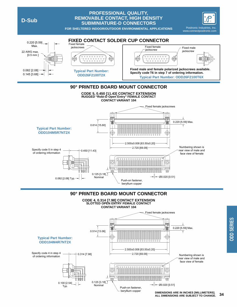
2.720 [69.09]
2.500±0.008 [63.50±0.20]
0.100 [2.54]Typ.
0.314 [7.98]Specify code 4 in step 4of ordering information
0.514 [13.06]0.220 [5.59] Max.
Fixed female jackscrews
0.125 [3.18]Nominal Ø0.020 [0.51]
Push-on fastener,beryllium copper
4221
221
Numbering shown isrear view of male andface view of female
2.720 [69.09]
2.500±0.008 [63.50±0.20]
Push-on fastener,beryllium copper
0.450 [11.43]Specify code 5 in step 4of ordering information
0.125 [3.18]Nominal
4221
0.614 [15.60]
Numbering shown isrear view of male andface view of female
221
0.220 [5.59] Max.
Fixed female jackscrews
Ø0.020 [0.51]0.082 [2.08] Typ.
0.220 [5.59]Max.
9
18
26
1
10
19
Fixed femalejackscrews
0.145 [3.68]0.082 [2.08]
22 AWG max.[0.5 mm ] 9
18
26
1
10
19
Fixed malejackscrewjackscrew
Fixed female
34DIMENSIONS ARE IN INCHES [MILLIMETERS].ALL DIMENSIONS ARE SUBJECT TO CHANGE.
D-SubPROFESSIONAL QUALITY,
REMOVABLE CONTACT, HIGH DENSITY SUBMINIATURE-D CONNECTORS
FOR SHELTERED INDOOR/OUTDOOR ENVIRONMENTAL APPLICATIONS Positronic Industries, Inc.www.connectpositronic.com
ODD
SERI
ES
Typical Part Number:ODD26F2100T2X
90° PRINTED BOARD MOUNT CONNECTORCODE 5, 0.450 [11.43] CONTACT EXTENSIONRUGGED “Robi-D Open Entry” FEMALE CONTACT
CONTACT VARIANT 104
FIXED CONTACT SOLDER CUP CONNECTOR
90° PRINTED BOARD MOUNT CONNECTORCODE 4, 0.314 [7.98] CONTACT EXTENSION
SLOTTED OPEN ENTRY FEMALE CONTACTCONTACT VARIANT 104
Typical Part Number:ODD104M4R7NT2X
Typical Part Number:ODD104M5R7NT2X
Fixed male and female polarized jackscrews available.Specify code T6 in step 7 of ordering information.
Typical Part Number: ODD26F2100T6X

0.984 [24.99]
0.492 [12.50] 0.190 [4.83]
0.090 [2.29] Typ.
A
A
1.312 [33.32]
0.656 [16.66]
0.090 [2.29] Typ.
0.380 [9.65]
B
B
B
1.852 [47.04]
0.926 [23.52] 0.650 [16.51]
0.090 [2.29] Typ.
2.500 [63.50]
1.250 [31.75] 0.973 [24.71]
0.095 [2.41] Typ.
2.406 [61.11]
1.203 [30.56] 0.903 [22.94]
D
0.095 [2.41] Typ.
2.500 [63.50]
1.250 [31.75] 0.967 [24.56]
0.095 [2.41] Typ.
0.975 [24.77]1.250 [31.75]
2.500 [63.50]
2.500 [63.50]
B Typ.0.095 [2.41] Typ.
0.903 [22.94]1.203 [30.56]
2.406 [61.11]
0.095 [2.41] Typ.
0.095 [2.41] Typ.
1.312 [33.32]
1.852 [47.04]
0.090 [2.29] Typ.
0.984 [24.99]
0.090 [2.29] Typ.
A
A
0.090 [2.29] Typ.
0.492 [12.50] 0.215 [5.46]
0.926 [23.52] 0.655 [16.64]
B Typ.
0.656 [16.66] 0.385 [9.78]
1.250 [31.75] 0.981 [24.92]
D
C
A
A
A
A
A
A
A
A
C
C C
C C
A
A
A
AC C
C C
B
B
B
C C
D-SubPROFESSIONAL QUALITY,
REMOVABLE CONTACT, HIGH DENSITY SUBMINIATURE-D CONNECTORS
FOR SHELTERED INDOOR/OUTDOOR ENVIRONMENTAL APPLICATIONSPositronic Industries, Inc.www.connectpositronic.com
35 DIMENSIONS ARE IN INCHES [MILLIMETERS].ALL DIMENSIONS ARE SUBJECT TO CHANGE.
ODD SERIES
90° AND STRAIGHT PRINTED BOARDCONTACT HOLE PATTERN
Mount connector with mating facepositioned to follow direction of arrows.
ODD104 MALE
ODD78 MALE
ODD62 MALE
ODD26 MALE
ODD15 MALE
ODD44 MALE
ODD104 FEMALE
ODD78 FEMALE
ODD62 FEMALE
ODD26 FEMALE
ODD15 FEMALE
ODD44 FEMALE
Suggest 0.123 ±0.003 [3.12 ±0.08] Øhole for mounting connector with push-on fasteners.
CODE NUMBER A B ØC
40.100[2.54]
0.100[2.54]
0.045[1.14]
3, 32, 50.078[1.98]
0.082[2.08]
0.035[0.89]
D
0.100[2.54]
0.123[3.12]

36DIMENSIONS ARE IN INCHES [MILLIMETERS].ALL DIMENSIONS ARE SUBJECT TO CHANGE.
D-SubPROFESSIONAL QUALITY,
REMOVABLE CONTACT, HIGH DENSITY SUBMINIATURE-D CONNECTORS
FOR SHELTERED INDOOR/OUTDOOR ENVIRONMENTAL APPLICATIONS Positronic Industries, Inc.www.connectpositronic.com
ODD
SERI
ES
AUTOMATIC FEEDCRIMP TOOL,
PNEUMATICALLY ACTUATEDPart No. 9550-1
MINIATURE STEP ADJUSTABLE TOOL(M22520/2-01)Part No. 9507
INSERTION/REMOVAL TOOL(M81969/1-04)
This fast cycling automatic feed crimp tool produces an 8indent crimp on wire sizes 20 AWG [0.5mm2] through 32AWG [0.03mm2]. ODD Series contacts must be ordered onreels.
To order, specify part number 9550-1. Foot control valve issupplied as a standard accessory.
This miniature step adjustable hand crimping tool producesan 8 indent crimp configuration and will crimp wire sizes 20AWG [0.5mm2] through 32 AWG [0.03mm2].
To crimp female contacts, order contact positioner 9502-3.To crimp male contacts, order contact positioner 9502-4.Each positioner is equipped with a data plate which gives thecorrect crimp-depth setting for each wire size, and must beused with 9507 tool frame for best results when crimpingODD Series contacts.
One end of this tool is used to insert contacts into ODDSeries connectors. The other end is used to extract contacts.This is accomplished by sliding the extraction tip down thewire into the connector until it bottoms against the contact. Aslight rotation while pushing will release the contacts, whichare then extracted by simultaneously pulling on the wire.
CRIMP TOOLSPOSITIONERS FOR
FC8122DPOSITIONERS FOR
MC8122D
9507, HAND CRIMP TOOL 9502-3 9502-4
9550-1, AUTOMATIC FEEDPNEUMATIC CRIMP TOOL
Supplied in reels Supplied in reels
WIRE SIZEAWG/[mm2]
AXIAL LOADPOUNDS/[N]
24 [0.25]
8 [36]
28 [0.08]
3 [13]
26 [0.12]
5 [22]
30 [0.05]
1.5 [4.4]
22 [0.3]
12[53]
Positronic recommended tools for ODD series contacts.
Positronic RecommendedConductor Tensile Strength
Conductor tensile strength values arederived using silver-tin plated copper wires.
Values may change depending upon whattype of wire is used.

D-SubPROFESSIONAL QUALITY,
REMOVABLE CONTACT, HIGH DENSITY SUBMINIATURE-D CONNECTORS
FOR SHELTERED INDOOR/OUTDOOR ENVIRONMENTAL APPLICATIONSPositronic Industries, Inc.www.connectpositronic.com
37 DIMENSIONS ARE IN INCHES [MILLIMETERS].ALL DIMENSIONS ARE SUBJECT TO CHANGE.
ODD SERIES
STEP 4 - Type of Contacts0 - Ordered Without Contacts.1 - Crimp, 22 AWG–30 AWG [0.3mm2–0.05mm2].2 - Solder cup, 22 AWG–30 AWG [0.3mm2–0.05mm2],
Removable contacts.21 - Solder cup, 22 AWG–30 AWG [0.3mm2–0.05mm2], Fixed con-
tacts.3 - Solder, Straight Printed Board Mount with 0.150 [3.81] Tail Length.32 - Solder, Straight Printed Board Mount with 0.300 [7.62] Tail Length.4 - Solder, 90° Printed Board Mount with 0.314 [7.98] Contact Extension.5 - Solder, 90° Printed Board Mount with 0.450 [11.43] Contact
Extension.
REELS FOR AUTOMATIC FEEDPNEUMATIC CRIMP TOOLS
Contacts may be supplied in plastic carriers, packaged in reels holding 2,000contacts for use with the automatic feed pneumatic crimp tools, catalog part number9550-1. The same type carrier is used for both male and female contacts.
All male and female crimp contacts can be ordered in reels by adding letter “R”after the contact part number, such as MC8122DR for a male contact andFC8122DR for a female contact.
1 2 3 4 5 6
ODD 62 F 5 R7 N T6
7
S
8 9STEP
STEP 1 - Basic SeriesODD Series
STEP 2 - ODD Series Connector Variants15, 26, 44, 62, 78, 104
STEP 3 - Connector GenderM - Male F - Female
*STEP 7 - Locking and Polarizing Systems0 - None.V3 - Lock Tab, connector front panel mounted.V5 - Lock Tab, connector rear panel mounted.VL - Lock Lever, used with Hoods Only.T - Fixed Female Jackscrews.T2 - Fixed Female Jackscrews.T6 - Fixed Male and Female Polarized Jackscrews.E - Rotating Male Jackscrews.E2 - Rotating Male Screw Locks.E6 - Rotating Male and Female Polarized Jackscrews.
*STEP 6 - Hoods and Push-On Fasteners0 - None.J - Hood, Top Opening, Plastic.L - Hood, Side Opening, Plastic.Y - Hood, Top Opening, Plastic with Rotating Male
Jackscrews. Available in size 78 and 104 only.Y6 - Hood, Top Opening, Plastic with Rotating Male and
Female Polarized Jackscrews. Available in size 78 and104 only.
Z - Hood, Top or Side Opening, Robust Extended Height,Composite and Plastic with Rotating Male Jackscrews.Available in size 15, 26, 44, 62 and 78 only.
H - Hood, Top Opening, Metal. Available in size 26, 44,62, and 78 only.
G - Hood, EMI/RFI, Metal.W - Hood, Top or Side Opening, Plastic. Available in size
15, 26, and 44 only.N - Push-on Fastener, for 90° Mounting.
**F - Ferrite Inductor.**Q - Ferrite Inductor with Push-on Fastener, for 90°
Mounting Brackets.
*STEP 5 - Mounting Style0 - Mounting Hole, 0.120 [3.05] Ø.02 - Mounting Hole, 0.154 [3.91] Ø.B3 - Bracket, Mounting, 90° Metal with Cross Bar.B8 - Bracket, Mounting, 90° Plastic with Cross Bar.F - Float Mounts, Universal.P - Threaded Post, Brass, 0.225 [5.71] Length.P2 - Threaded Post, Nylon, 0.225 [5.71] Length.R2 - Bracket, Mounting, 90° Metal, Swaged to Connector with 4-40
Thread Fixed Female Jackscrews with Cross Bar.R6 - Bracket, Mounting, 90° Metal, Swaged to Connector with 0.120
[3.05] Ø Mounting Hole with Cross Bar.R7 - Bracket, Mounting, 90° Metal, Swaged to Connector with 4-40
Threads with Cross Bar.R8 - Bracket, Mounting, 90° Metal, Swaged to Connector with 4-40
Locknut with Cross Bar.S - Swaged Spacer, 4-40 Threads, 0.225 [5.71] Length.S2 - Swaged Spacer, 4-40 Threads, 0.125 [3.18] Length.S5 - Swaged Locknut, 4-40 Threads.S6 - Swaged Spacer with Push-on Fasteners, 4-40 Threads, 0.225
[5.71] Length.S7 - Swaged Spacer with Push-on Fastener for use with Ferrite
Inductor, 4-40 Threads, 0.375 [9.53] Length.
STEP 9 - Special OptionsConsult Sales Department.
ORDERING INFORMATION – CODE NUMBERING SYSTEMSpecify Complete Connector By Following Steps 1 Through 9
Insert “0” When Step Is Not Used
*For additional information on accessories listed in steps 5, 6 and 7, see Accessory Catalog.
**Ferrite inductor is available on contact types 32 and 5 only.
For ODD crimping information, see DD Series, p. 26 & 27.
Enlarged section ofplastic contact carrier.
STEP 8 - Shell Options0 - Zinc Plated with Dichromate Seal.S - Stainless Steel.X - Tin Plated.Z - Tin Plated and Dimpled.

38DIMENSIONS ARE IN INCHES [MILLIMETERS].ALL DIMENSIONS ARE SUBJECT TO CHANGE.
D-SubMILITARY QUALITY,
CRIMP REMOVABLE CONTACTSUBMINIATURE-D CONNECTORS
FOR MILITARY AND SEVERE INDUSTRIAL ENVIRONMENTAL APPLICATIONS Positronic Industries, Inc.www.connectpositronic.com
RD S
ERIE
S
Size 20 Signal andThermocouple Contacts,
Crimp RemovableMilitary/Industrial
Quality ConnectorsIEC Publication 807-3
Performance Level OneMIL-DTL-24308 and MIL-C-39029
U.L. Recognized CSA RecognizedFile #E49351 File #LR54219
TelecommunicationU.L. File #14098
Rhapso-D Series connectors are Military/Industrial quality rectangu-lar connectors designed for use in sheltered, mildly corrosive environ-ments having a wide range of temperature, pressure and humiditychanges. These crimp removable contact connectors are qualified toMIL-DTL-24308 and MIL-C-39029, and will meet the performancerequirements of IEC 807-3, Performance Level One.
Rhapso-D Series connectors utilize precision machined contactswith closed barrel, crimp terminations. The female contact features arugged closed entry design contact with stainless steel shroud. A“Robi-D Open Entry” female contact is also available.
Six standard connector variants are offered in arrangements of 9,15, 25, 29, 37 and 50 contacts. Rhapso-D Series connectors are mate-able and compatible with all D-Subminiature connectors conforming toMIL-DTL-24308, IEC 807-2 and IEC 807-3.
A wide assortment of cable support hoods and locking systems isavailable from stock.
Rhapso-D Series connectors conform to EIA RS 232 and RS 449,and CCITT X.24 interface connection requirements.
RHAPSO-D SERIES TECHNICAL CHARACTERISTICSMATERIALS AND FINISHES:Insulator: Glass filled DAP per ASTM-D-5948,
SDG-F, UL 94V-0, green color.
Contacts: Signal: Male contacts – precision machinedbrass. Female contacts – precisionmachined high tensile copper alloy withstainless steel shroud or open entryRobi-D design.
Thermocouple: See page 41.
Contact Plating: Military performance – 0.000050 inch[1.27 microns] gold over copper plate.Industrial performance – gold flash overnickel plate. Other finishes available uponrequest.
Shells: Steel with tin plate; zinc and cadmiumplate with dichromate seal, stainlesssteel, passivated. Other materials andfinishes available upon request.
Mounting Spacers: Brass, zinc plate with dichromate seal.
Jackscrew Systems: Steel with zinc plate and dichromateseal, or clear zinc plate.
Vibration Lock Systems: Slide lock and lock tabs, steel with nick-el plate.
Hoods: Thermoplastic UL 94V-0. Composite,brass or steel with zinc plate anddichromate seal.
ELECTRICAL CHARACTERISTICS:Contact Current Rating: 7.5 amperes nominal.
Initial Contact Resistance: 0.005 ohms maximum.
Proof Voltage: 1000 V r.m.s.
Insulator Resistance: 5 G ohms.
Clearance and CreepageDistance [minimum]: 0.039 inch [1.0mm].
Working Voltage: 300 V r.m.s.
CLIMATIC CHARACTERISTICS:Temperature Range: -55°C to +125°C.
Damp Heat, Steady State: 21 days.
MECHANICAL CHARACTERISTICS:Removable Contacts: Insert contact to rear face of insulator
and release from rear face of insulator.Size 20 contact, male – 0.040 inch[1.02mm] diameter; female – closedentry design with stainless steel shroudor open entry Robi-D design.
Contact RetentionIn Insulator: 9 lbs. [40 N].
Contact Terminations: Closed barrel crimp, wire sizes 18 AWG[1.0mm2] through 30 AWG [0.05mm2].
Shells: Male shells may be dimpled for EMI/ESDground paths.
Polarization: Trapezoidally shaped shells and polar-ized jackscrews.
Locking Systems: Jackscrews and vibration locking sys-tems.
Mechanical Operations: 1000 operations minimum per IEC 512-5for closed entry female contact.500 operations per IEC 512-5 for “Robi-DOpen Entry” design female contact.

222120
31 2
2423 26 2725 3028 29 32 3331
654 87 1211109 1413
3634 35 37
171615 1918
383534 3736 39 40 4341 42
5
18 20 2119
21 43
242322 272625
76 1098
45 4644 4947 48 50
333028 29 3231
131211 161514 17
9876
1 542 3
15141211109 13
321 87654
14
1 2
2524232221201817 191615
876543 1312109 11
21
11 12
20
21
26
1716
242322
13 14 15
25 2927 28
1918
76543 1098
D-SubMILITARY QUALITY,
CRIMP REMOVABLE CONTACTSUBMINIATURE-D CONNECTORS
FOR MILITARY AND SEVERE INDUSTRIAL ENVIRONMENTAL APPLICATIONSPositronic Industries, Inc.www.connectpositronic.com
39 DIMENSIONS ARE IN INCHES [MILLIMETERS].ALL DIMENSIONS ARE SUBJECT TO CHANGE.
RD SERIES
CONTACT VARIANTSFACE VIEW OF MALE OR REAR VIEW OF FEMALE
RD 9 RD 15 RD 25
RD 50RD 37RD 29
CONNECTORVARIANT SIZES
A±0.015[0.38]
B±0.005[0.13]
B1±0.005[0.13]
C±0.005[0.13]
D±0.005[0.13]
D1±0.005[0.13]
E±0.015[0.38]
G±0.010[0.25]
H±0.010[0.25]
K±0.005[0.13]
M±0.010[0.25]
RD 9 M1.213[30.81]
0.666[16.92]
0.984[24.99]
0.329[8.36]
0.494[12.55]
0.759[19.28]
0.422[10.72]
0.233[5.92]
0.422[10.72]
RD 9 F1.213[30.81]
0.643[16.33]
0.984[24.99]
0.311[7.90]
0.494[12.55]
0.759[19.28]
0.422[10.72]
0.243[6.17]
0.429[10.90]
RD 15 M1.541[39.14]
0.994[25.25]
1.312[33.32]
0.329[8.36]
0.494[12.55]
1.083[27.51]
0.422[10.72]
0.233[5.92]
0.422[10.72]
RD 15 F1.541[39.14]
0.971[24.66]
1.312[33.32]
0.311[7.90]
0.494[12.55]
1.083[27.51]
0.422[10.72]
0.243[6.17]
0.429[10.90]
RD 25 M2.088[53.04]
1.534[38.96]
1.852[47.04]
0.329[8.36]
0.494[12.55]
1.625[41.28]
0.422[10.72]
0.230[5.84]
0.426[10.82]
RD 25 F2.088[53.04]
1.511[38.38]
1.852[47.04]
0.311[7.90]
0.494[12.55]
1.625[41.28]
0.422[10.72]
0.243[6.17]
0.429[10.90]
RD 29 M1.770[44.96]
1.274[32.36]
1.534[38.96]
0.450[11.43]
0.605[15.37]
1.322[33.58]
0.539[13.69]
0.217[5.51]
0.426[10.82]
RD 29 F1.770[44.96]
1.251[31.78]
1.534[38.96]
0.431[10.95]
0.605[15.37]
1.322[33.58]
0.539[13.69]
0.237[6.02]
0.429[10.90]
RD 37 M2.729[69.32]
2.182[55.42]
2.500[63.50]
0.329[8.36]
0.494[12.55]
2.272[57.71]
0.422[10.72]
0.230[5.84]
0.426[10.82]
RD 37 F2.729[69.32]
2.159[54.84]
2.500[63.50]
0.311[7.90]
0.494[12.55]
2.272[57.71]
0.422[10.72]
0.243[6.17]
0.429[10.90]
RD 50 M2.635[66.93]
2.079[52.81]
2.406[61.11]
0.441[11.20]
0.605[15.37]
2.178[55.32]
0.534[13.56]
0.230[5.84]
0.426[10.82]
RD 50 F2.635[66.93]
2.064[52.43]
2.406[61.11]
0.423[10.74]
0.605[15.37]
2.178[55.32]
0.534[13.56]
0.243[6.17]
0.429[10.90]
KM
G
H
0.375 [9.53]Max.
10° Typ.
Ø0.120±0.005 [Ø3.05±0.13] Mounting hole, two places
0.036±0.008[0.91±0.20]
0.050±0.010[1.27±0.25]
E
B1 B
A
C
D1 D
two places (02 option)Ø0.154 [3.91] Mounting hole,
Ø0.120±0.005 [Ø3.05±0.13] Mounting hole, two places for stainless steel shell (0 option) [
Mounting hole, two placesTotal diametral float0.032 [0.81] Ø0.086+0.005
-0.000
0.120±0.010 [3.08±0.25]
+0.13-0.00Ø2.18 ]
STANDARD SHELL ASSEMBLY
OPTIONAL SHELL ASSEMBLY WITH UNIVERSAL FLOAT MOUNTS [F]OPTIONAL SHELL ASSEMBLY [0, 02]

øB
A
0.170[4.32]
øC
A
øC
øB0.170[4.32]
Ø0.040[1.02]
*Color Code*Color Code
Stainless SteelShroud
øB
øCA
0.170[4.32]
40DIMENSIONS ARE IN INCHES [MILLIMETERS].ALL DIMENSIONS ARE SUBJECT TO CHANGE.
D-SubMILITARY QUALITY,
CRIMP REMOVABLE CONTACTSUBMINIATURE-D CONNECTORS
FOR MILITARY AND SEVERE INDUSTRIAL ENVIRONMENTAL APPLICATIONS Positronic Industries, Inc.www.connectpositronic.com
RD S
ERIE
S
Material - Phosphor bronze.Plating - Gold flash over nickel.
CRIMP CONTACTSCLOSED CRIMP BARREL
MALE CONTACT
FEMALE CONTACT “Robi-D Open Entry” DESIGN20/22/24 AWG [0.5/0.3/0.25 mm2]
FEMALE CONTACT“CLOSED ENTRY” DESIGN
Material - Leaded nickel copper.Plating - Gold flash over nickel or 0.000050 inch [1.27µ]
gold over copper for military specification contacts.*Color Code - ORANGE/BLUE/GRAY for military
specification contacts.
Material - Brass.Plating - Gold flash over nickel or 0.000050 inch [1.27µ]
gold over copper for military specification contacts.*Color Code - ORANGE/BLUE/WHITE for military
specification contacts.
PART NUMBER WIRE SIZEAWG/[mm2]
A ØB ØC
FC6020D20 / 22 / 24
[0.5/0.3/0.25]0.538[13.67]
0.045[1.14]
0.066[1.68]
FC6026D26 / 28 / 30
[0.12/0.08/0.05]0.538[13.67]
0.027[0.69]
0.066[1.68]
PART NUMBER WIRE SIZEAWG/[mm2]
A ØB ØC
MC6020D20 / 22 / 24
[0.5/0.3/0.25]0.550[13.97]
0.045[1.14]
0.066[1.68]
MC6026D26 / 28 / 30
[0.12/0.08/0.05]0.550[13.97]
0.027[0.69]
0.066[1.68]
*M39029/63-36820 / 22 / 24
[0.5/0.3/0.25]0.538[13.67]
0.045[1.14]
0.066[1.68]
*M39029/64-36920 / 22 / 24
[0.5/0.3/0.25]0.550[13.97]
0.045[1.14]
0.066[1.68]
Note: *C60**D contacts can be used in the SD series.Crimp contacts may be supplied kitted with connector or ordered separately. See page 42 for crimp tool information.
REELS FOR AUTOMATIC FEED PNEUMATIC CRIMP TOOLS
Contacts may be supplied in plastic carriers, packagedin reels holding 2,000 contacts for use with the automat-ic feed pneumatic crimp tools, catalog part number 9550-1. The same type carrier is used for both male andfemale contacts.
All male and female crimp contacts can be ordered inreels by adding letter “R” after the contact part number, suchas MC6020DR for a male contact and FC6026DR for afemale contact.Enlarged section of
plastic contact carriers
For RD crimping information,see SD Series, p. 16 and 17.

D-SubMILITARY QUALITY,
CRIMP REMOVABLE CONTACTSUBMINIATURE-D CONNECTORS
FOR MILITARY AND SEVERE INDUSTRIAL ENVIRONMENTAL APPLICATIONSPositronic Industries, Inc.www.connectpositronic.com
41 DIMENSIONS ARE IN INCHES [MILLIMETERS].ALL DIMENSIONS ARE SUBJECT TO CHANGE.
RD SERIES
Chromel® and Alumel® are registered trademarks ofHoskins Manufacturing Company.
For more information on the availability of Type J thermocouple contacts,
and information about thermocouple contacts with PCB solder termination, please contact Technical Sales.
For RD crimpinginformation,see SD Series,p. 16 and 17.
0.927 [23.55]
ø0.040[1.02]
0.170[4.32]
0.916 [23.26]Ø0.085[2.16]
Ø0.054[1.38]
StainlessSteel Shroud
0.170[4.32]
Ø0.055[1.40]
Ø0.086[2.18]
Material - Phosphor bronze.Plating - Gold flash over nickel.
Part Number: FC6018D
For RD crimping information, see SD Series, p. 16 and 17.
Additional plating options available by adding suffix to part numberadd -14 for 0.000030 [0.76 microns] gold over nickel add -50 for 0.000050 [1.27 microns] gold over copperExample: FC6018D-14 Example: MC6018D-50
Part Number: MC6018D
Material - Brass.Plating - Gold flash over nickel.
CRIMP CONTACTS18 AWG [1.0mm2] max.
THERMOCOUPLE CONTACTS
FEMALE CONTACT “CLOSED ENTRY” DESIGN
MALE CONTACT
0.550 [13.97]
0.170[4.32]
Ø0.045[1.14]
Ø0.066[1.68]
Ø0.045[1.14]
Ø0.066[1.68]
0.170[4.32]
0.538 [13.67]
Ø0.040[1.02]
*Color Code *Color Code
MALE CONTACT FEMALE CONTACT
TYPE MATERIALMALE
PART NUMBERFEMALE
PART NUMBERCOLORCODE
WIRE SIZEAWG [mm2]
K Chromel® (+) MC6020DCH† FC6020DCH†† White 20 / 22 / 24[0.5 / 0.3 / 0.25]
K Alumel®(-) MC6020DAL† FC6020DAL†† Green 20 / 22 / 24[0.5 / 0.3 / 0.25]
T Copper (+) MC6020DCU† FC6020DCU†† Red 20 / 22 / 24[0.5 / 0.3 / 0.25]
T Constantan (-) MC6020DCO† FC6020DCO†† Yellow 20 / 22 / 24[0.5 / 0.3 / 0.25]
E Chromel® (+) MC6020DCH† FC6020DCH†† White 20 / 22 / 24[0.5 / 0.3 / 0.25]
E Constantan (-) MC6020DCO† FC6020DCO†† Yellow 20 / 22 / 24[0.5 / 0.3 / 0.25]
†Dimensionally equivalent to M39029/64-369††Dimensionally equivalent to M39029/63-368

42DIMENSIONS ARE IN INCHES [MILLIMETERS].ALL DIMENSIONS ARE SUBJECT TO CHANGE.
D-SubMILITARY QUALITY,
CRIMP REMOVABLE CONTACTSUBMINIATURE-D CONNECTORS
FOR MILITARY AND SEVERE INDUSTRIAL ENVIRONMENTAL APPLICATIONS Positronic Industries, Inc.www.connectpositronic.com
RD S
ERIE
S
AUTOMATIC FEEDCRIMP TOOL,
PNEUMATICALLY ACTUATEDPart No. 9550-1
MINIATURE STEP ADJUSTABLE TOOL(M22520/2-01)Part No. 9507
INSERTION/REMOVAL TOOL(M81969/1-02)
This fast cycling automatic feed crimp tool produces an 8indent crimp on wire sizes 20 AWG [0.5mm2] through 32AWG [0.03mm2]. Rhapso-D Series contacts must beordered on reels.
To order, specify part number 9550-1. Foot control valve issupplied as a standard accessory.
This miniature 8 step adjustable hand crimping tool producesan 8 indent crimp configuration and will crimp wire sizes 18AWG [1.0mm2] through 32 AWG [0.03mm2].
To crimp wire size 18 AWG [1.0mm2], order contact position-er 9502-11. To crimp wire size 20 AWG [0.5mm2] through 30AWG [0.05mm2], order contact positioner 9502-5. Each posi-tioner is equipped with a data plate which gives the correctcrimp-depth setting for each wire size, and must be used with9507 tool frame for best results when crimping Rhapso-DSeries contacts.
One end of this tool is used to insert contacts into Rhapso-DSeries connectors. The other end is used to extract contacts.This is accomplished by sliding the extraction tip down thewire into the connector until it bottoms against the contact. Aslight rotation while pushing will release the contacts, whichare then extracted by simultaneously pulling on the wire.Positronic Recommended
Conductor Tensile Strength
CRIMP TOOLS
POSITIONERS FORFC6020D, MC6020D,FC6026D, MC6026D,
FC6120DM39029/63-368M39029/64-369
POSITIONERS FORFC6018D, MC6018D,
FC6118D
9507, HAND CRIMP TOOL 9502-5 9502-11
9550-1, AUTOMATIC FEEDPNEUMATIC CRIMP TOOL
Supplied in reels Not Available
WIRE SIZEAWG/[mm2]
AXIAL LOADPOUNDS/[N]
20 [0.5]
20[89]
24 [0.25]
8 [36]
22 [0.3]
12[53]
26 [0.12]
5 [22]
18 [1.0]
28 [125]
28 [0.08]
3 [13]
30 [0.05]
1.5[6.7]
Conductor tensile strength values are derived usingsilver-tin plated copper wires.
Values may change depending upon what type of wireis used.
Positronic recommended tools for RD series contacts.For more information see contact crimp tools
and accessories page.

D-SubMILITARY QUALITY,
CRIMP REMOVABLE CONTACTSUBMINIATURE-D CONNECTORS
FOR MILITARY AND SEVERE INDUSTRIAL ENVIRONMENTAL APPLICATIONSPositronic Industries, Inc.www.connectpositronic.com
43 DIMENSIONS ARE IN INCHES [MILLIMETERS].ALL DIMENSIONS ARE SUBJECT TO CHANGE.
RD SERIES
ORDERING INFORMATION – CODE NUMBERING SYSTEM
Specify Complete Connector By Following Steps 1 Through 9Insert “0” When Step Is Not Used
STEP
STEP 1 - Basic SeriesRD Series
STEP 2 - RD Series Connector Variants9, 15, 25, 29, 37, 50
STEP 3 - Connector GenderM - Male F - Female
STEP 4 - Type of Contacts0 - Ordered Without Contacts.1 - Crimp, 20 AWG–24 AWG [0.5mm2–0.25mm2].12 - Crimp, 26 AWG–30 AWG [0.12mm2–0.08mm2].14 - Crimp, 20 AWG–24 AWG [0.5mm2–0.25mm2]
“Robi-D Open Entry” female contact.
*STEP 7 - Locking and Polarizing Systems0 - None.V3 - Lock Tab, connector front panel mounted.V5 - Lock Tab, connector rear panel mounted.VL - Lock Lever, used with Hoods Only.T - Fixed Female Jackscrews.T2 - Fixed Female Jackscrews.T6 - Fixed Male and Female Polarized Jackscrews.E - Rotating Male Jackscrews.E2 - Rotating Male Screw Locks.E6 - Rotating Male and Female Polarized Jackscrews.
*STEP 6 - Hoods
0 - None.J - Hood, Top Opening, Plastic.L - Hood, Side Opening, Plastic.Y - Hood, Top Opening, Plastic with Rotating Male Jackscrews.
Available in size 50 only.Y6 - Hood, Top Opening, Plastic with Rotating Male and Female
Polarized Jackscrews. Available in size 50 only.Z - Hood, Top or Side Opening, Robust Extended Height,
Composite and Plastic with Rotating Male Jackscrews.Available in size 9, 15, 25, 37, and 50 only.
H - Hood, Top Opening, Metal. Available in size 15, 25, 37, and 50 only.
G - Hood, EMI/RFI, Metal. Available in size 9, 15, 25, 37, and size 50 only.
W - Hood, Top or Side Opening, Plastic. Available in size 9, 15, and 25 only.
STEP 8 - Shell Options0 - Zinc Plated with Dichromate Seal.S - Stainless Steel.X - Tin Plated.Z - Tin Plated and Dimpled.C - Cadmium plated with Dichromate Seal.
*STEP 5 - Mounting Style0 - Mounting Hole, 0.120 [3.05] Ø.02 - Mounting Hole, 0.154 [3.91] Ø.F - Float Mounts, Universal.S2 - Swaged Spacer, 4-40 Threads, 0.125 [3.18] Length.S5 - Swaged Locknut, 4-40 Threads.
STEP 9 - Special OptionsConsult Sales Department.
*For additional information on accessories listed in steps 5, 6and 7, see Accessory Catalog.
For RD crimping information,see SD Series, p. 16 and 17.
1 2 3 4 5 6
RD 15 M 12 0 H 0
7
0
8 9

44DIMENSIONS ARE IN INCHES [MILLIMETERS].ALL DIMENSIONS ARE SUBJECT TO CHANGE.
D-SubPROFESSIONAL QUALITY,
CRIMP REMOVABLE CONTACTSUBMINIATURE-D CONNECTORS
FOR SHELTERED INDOOR/OUTDOOR ENVIRONMENTAL APPLICATIONS Positronic Industries, Inc.www.connectpositronic.com
ORD
SERI
ES
Size 20 Signal andThermocouple Contacts,
Removable Crimp
Industrial QualityConnectors
IEC Publication 807-3Performance Level Two
ORD Series connectors are low cost, industrial/professional qualityD–Subminiature connectors with closed barrel crimp removable con-tacts. ORD Series connectors are recommended for use in sheltered,mildly corrosive environments having a wide range of temperatureswith normal ventilation where high performance is required.
ORD Series connectors utilize precision–machined contacts to pro-vide durability. Female contacts feature the low cost, high performanceRobi–D Open Entry design. ORD Series connectors meet the perfor-mance requirements of IEC 807–3, Performance Level Two. Closedentry female contacts are available upon request.
Six [6] standard contact variants are offered in arrangements of 9,15, 25, 29, 37, and 50 contacts. ORD Series connectors are mateableand compatible with all D–Subminiature connectors conforming toMIL–DTL–24308, IEC 807–2, and IEC 807–3.
A wide assortment of cable support hoods and locking systems isavailable from stock.
ORD Series connectors also conform to EIA RS 232 and RS 449,and CCITTX.24 interface connection requirements.
ORD SERIES TECHNICAL CHARACTERISTICSMATERIALS AND FINISHES:Insulators: Glass filled DAP per ASTM–D–5948,
SDG–F, UL 94V-0, green color.
Contacts: Signal: Male contacts – precision machinedbrass.Female contacts – precision machinedhigh tensile copper alloy with rugged“Robi–D Open Entry” design.
Thermocouple: See page 41.
Contact Plating: Industrial performance – gold flash overnickel plate. Other finishes available uponrequest.
Shells: Steel with tin plate; zinc plate withdichromate seal, or stainless steel,passivated. Other materials and finishesavailable upon request.
Mounting Spacers: Brass, zinc plate with dichromate seal,or clear zinc plate.
Vibration Lock Systems: Slide lock and lock tabs, steel with nick-el plate.
Jackscrew Systems: Steel with zinc plate and dichromateseal, or clear zinc plate.
Hoods: Thermoplastic UL 94V-0. Composite,brass or steel with zinc plate anddichromate seal.
ELECTRICAL CHARACTERISTICS:Contact Current Rating: 7.5 amperes nominal.
Initial Contact Resistance: 0.005 ohms maximum.
Proof Voltage: 1000 V r.m.s.
Insulator Resistance: 5 G ohms.
Clearance and CreepageDistance [minimum]: 0.039 inch [1.0mm].
Working Voltage: 300 V r.m.s.
CLIMACTIC CHARACTERISTICS:Temperature Range: -55°C to +125°C.
Damp Heat, Steady State: 10 days.
MECHANICAL CHARACTERISTICS:Removable Contacts: Insert contact to rear face of insulator
and release from rear face of insulator.Size 20 male contact – 0.040 inch[1.02mm] diameter;Size 20 female contacts – Rugged “Robi-D Open Entry” design.
Contact RetentionIn Insulator: 9 lbs. [40 N].
Contact Terminations: Closed barrel crimp, wire sizes 18 AWG[1.0mm2] through 24 AWG [0.25mm2].
Shells: Tin–plated male shells may be dimpled forEMI/ESD ground paths.
Polarization: Trapezoidally shaped shells and polar-ized jackscrews.
Locking Systems: Jackscrews and vibration locking sys-tems.
Mechanical Operations: 500 operations minimum per IEC 512-5for “ ‘Robi–D’ Open Entry” design.

KM
G
H
0.375 [9.53]Max.
10° Typ.
Ø0.120±0.005 [Ø3.05±0.13] Mounting hole, two places
0.036±0.008[0.91±0.20]
0.050±0.010[1.27±0.25]
E
B1 B
A
C
D1 D
two places (02 option)Ø0.154 [3.91] Mounting hole,
Ø0.120±0.005 [Ø3.05±0.13] Mounting hole, two places for stainless steel shell (0 option) [
Mounting hole, two placesTotal diametral float0.032 [0.81] Ø0.086+0.005
-0.000
0.120±0.010 [3.08±0.25]
+0.13-0.00Ø2.18 ]
STANDARD SHELL ASSEMBLY
OPTIONAL SHELL ASSEMBLY WITH UNIVERSAL FLOAT MOUNTS [F]
OPTIONAL SHELL ASSEMBLY [0, 02]
222120
31 2
2423 26 2725 3028 29 32 3331
654 87 1211109 1413
3634 35 37
171615 1918
383534 3736 39 40 4341 42
5
18 20 2119
21 43
242322 272625
76 1098
45 4644 4947 48 50
333028 29 3231
131211 161514 17
9876
1 542 3
15141211109 13
321 87654
14
1 2
2524232221201817 191615
876543 1312109 11
21
11 12
20
21
26
1716
242322
13 14 15
25 2927 28
1918
76543 1098
D-SubPROFESSIONAL QUALITY,
CRIMP REMOVABLE CONTACTSUBMINIATURE-D CONNECTORS
FOR SHELTERED INDOOR/OUTDOOR ENVIRONMENTAL APPLICATIONSPositronic Industries, Inc.www.connectpositronic.com
45 DIMENSIONS ARE IN INCHES [MILLIMETERS].ALL DIMENSIONS ARE SUBJECT TO CHANGE.
ORD SERIES
CONTACT VARIANTSFACE VIEW OF MALE OR REAR VIEW OF FEMALE
CONNECTORVARIANT SIZES
A±0.015[0.38]
B±0.005[0.13]
B1±0.005[0.13]
C±0.005[0.13]
D±0.005[0.13]
D1±0.005[0.13]
E±0.015[0.38]
G±0.010[0.25]
H±0.010[0.25]
K±0.005[0.13]
M±0.010[0.25]
ORD 9 M1.213[30.81]
0.666[16.92]
0.984[24.99]
0.329[8.36]
0.494[12.55]
0.759[19.28]
0.422[10.72]
0.233[5.92]
0.422[10.72]
ORD 9 F1.213[30.81]
0.643[16.33]
0.984[24.99]
0.311[7.90]
0.494[12.55]
0.759[19.28]
0.422[10.72]
0.243[6.17]
0.429[10.90]
ORD 15 M1.541[39.14]
0.994[25.25]
1.312[33.32]
0.329[8.36]
0.494[12.55]
1.083[27.51]
0.422[10.72]
0.233[5.92]
0.422[10.72]
ORD 15 F1.541[39.14]
0.971[24.66]
1.312[33.32]
0.311[7.90]
0.494[12.55]
1.083[27.51]
0.422[10.72]
0.243[6.17]
0.429[10.90]
ORD 25 M2.088[53.04]
1.534[38.96]
1.852[47.04]
0.329[8.36]
0.494[12.55]
1.625[41.28]
0.422[10.72]
0.230[5.84]
0.426[10.82]
ORD 25 F2.088[53.04]
1.511[38.38]
1.852[47.04]
0.311[7.90]
0.494[12.55]
1.625[41.28]
0.422[10.72]
0.243[6.17]
0.429[10.90]
ORD 29 M1.770[44.96]
1.274[32.36]
1.534[38.96]
0.450[11.43]
0.605[15.37]
1.322[33.58]
0.539[13.69]
0.217[5.51]
0.426[10.82]
ORD 29 F1.770[44.96]
1.251[31.78]
1.534[38.96]
0.431[10.95]
0.605[15.37]
1.322[33.58]
0.539[13.69]
0.237[6.02]
0.429[10.90]
ORD 37 M2.729[69.32]
2.182[55.42]
2.500[63.50]
0.329[8.36]
0.494[12.55]
2.272[57.71]
0.422[10.72]
0.230[5.84]
0.426[10.82]
ORD 37 F2.729[69.32]
2.159[54.84]
2.500[63.50]
0.311[7.90]
0.494[12.55]
2.272[57.71]
0.422[10.72]
0.243[6.17]
0.429[10.90]
ORD 50 M2.635[66.93]
2.079[52.81]
2.406[61.11]
0.441[11.20]
0.605[15.37]
2.178[55.32]
0.534[13.56]
0.230[5.84]
0.426[10.82]
ORD 50 F2.635[66.93]
2.064[52.43]
2.406[61.11]
0.423[10.74]
0.605[15.37]
2.178[55.32]
0.534[13.56]
0.243[6.17]
0.429[10.90]
ORD 9 ORD 15
ORD 29
ORD 25
ORD 37 ORD 50

0.916 [23.26]Ø0.086[2.19]
Ø0.055[1.40] 0.170
[4.55]
Ø0.086[2.19]
0.927 [23.56]
Ø0.040[1.02]
Ø0.055[1.40]
0.170[4.55]
REELS FOR AUTOMATIC FEED PNEUMATIC CRIMP TOOLS
Contacts may be supplied in plastic carriers, packagedin reels holding 2,000 contacts for use with the automat-ic feed pneumatic crimp tools, catalog part number9550-1. The same type carrier is used for both male andfemale contacts.
All male and female crimp contacts can be ordered inreels by adding letter “R” after the contact part number,such as MC6020DR for a male contact and FC6120DRfor a female contact.Enlarged section of
plastic contact carriers
MC6018DFC6118D
Material – Phosphor bronze.Plating – Gold flash over nickel.
Material – Brass.Plating – Gold flash over nickel.
Ø0.040[1.00]
øC
øB
A
øB
øCA
0.165[4.19]
0.165[4.19]
46DIMENSIONS ARE IN INCHES [MILLIMETERS].ALL DIMENSIONS ARE SUBJECT TO CHANGE.
D-SubPROFESSIONAL QUALITY,
CRIMP REMOVABLE CONTACTSUBMINIATURE-D CONNECTORS
FOR SHELTERED INDOOR/OUTDOOR ENVIRONMENTAL APPLICATIONS Positronic Industries, Inc.www.connectpositronic.com
ORD
SERI
ES
FEMALE CONTACTRUGGED ‘ROBI–D’ OPEN ENTRY DESIGN
MALE CONTACT
Material – Brass.Plating – Gold flash over nickel.
Material – Phosphor bronze.Plating – Gold flash over nickel.
PART NUMBER WIRE SIZE AØB
±0.005[0.13]
ØC±0.005[0.13]
FC6120D20 / 22 / 24
[0.5/0.3/0.25]0.538[13.67]
0.045[1.14]
0.066[1.68]
MC6020D20 / 22 / 24
[0.5/0.3/0.25]0.550[13.97]
0.045[1.14]
0.066[1.68]
CRIMP CONTACTSCLOSED CRIMP BARREL
Thermocouple contacts are available.See page 41.
Closed entry contacts are available.See page 43.
Additional plating options available by adding suffix to part numberadd -14 for 0.000030 [0.76 microns] gold over nickel add -50 for 0.000050 [1.27 microns] gold over copperExample: FC6120D-14 Example: MC6018D-50
CRIMP CONTACTS18 AWG [1.0mm2]
FEMALE CONTACTRUGGED ‘ROBI–D’ OPEN ENTRY DESIGN
MALE CONTACT
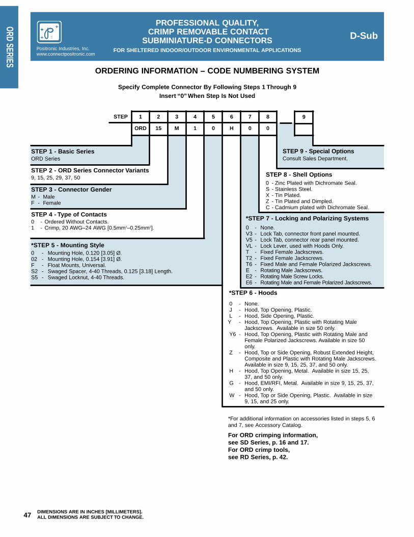
D-SubPROFESSIONAL QUALITY,
CRIMP REMOVABLE CONTACTSUBMINIATURE-D CONNECTORS
FOR SHELTERED INDOOR/OUTDOOR ENVIRONMENTAL APPLICATIONSPositronic Industries, Inc.www.connectpositronic.com
47 DIMENSIONS ARE IN INCHES [MILLIMETERS].ALL DIMENSIONS ARE SUBJECT TO CHANGE.
ORD SERIES
ORDERING INFORMATION – CODE NUMBERING SYSTEM
Specify Complete Connector By Following Steps 1 Through 9Insert “0” When Step Is Not Used
STEP
STEP 1 - Basic SeriesORD Series
STEP 2 - ORD Series Connector Variants9, 15, 25, 29, 37, 50
STEP 3 - Connector GenderM - Male F - Female
STEP 4 - Type of Contacts0 - Ordered Without Contacts.1 - Crimp, 20 AWG–24 AWG [0.5mm2–0.25mm2].
*STEP 7 - Locking and Polarizing Systems0 - None.V3 - Lock Tab, connector front panel mounted.V5 - Lock Tab, connector rear panel mounted.VL - Lock Lever, used with Hoods Only.T - Fixed Female Jackscrews.T2 - Fixed Female Jackscrews.T6 - Fixed Male and Female Polarized Jackscrews.E - Rotating Male Jackscrews.E2 - Rotating Male Screw Locks.E6 - Rotating Male and Female Polarized Jackscrews.
*STEP 6 - Hoods
0 - None.J - Hood, Top Opening, Plastic.L - Hood, Side Opening, Plastic.
Y - Hood, Top Opening, Plastic with Rotating MaleJackscrews. Available in size 50 only.
Y6 - Hood, Top Opening, Plastic with Rotating Male andFemale Polarized Jackscrews. Available in size 50only.
Z - Hood, Top or Side Opening, Robust Extended Height,Composite and Plastic with Rotating Male Jackscrews.Available in size 9, 15, 25, 37, and 50 only.
H - Hood, Top Opening, Metal. Available in size 15, 25,37, and 50 only.
G - Hood, EMI/RFI, Metal. Available in size 9, 15, 25, 37,and 50 only.
W - Hood, Top or Side Opening, Plastic. Available in size9, 15, and 25 only.
STEP 8 - Shell Options0 - Zinc Plated with Dichromate Seal.S - Stainless Steel.X - Tin Plated.Z - Tin Plated and Dimpled.C - Cadmium plated with Dichromate Seal.
*STEP 5 - Mounting Style0 - Mounting Hole, 0.120 [3.05] Ø.02 - Mounting Hole, 0.154 [3.91] Ø.F - Float Mounts, Universal.S2 - Swaged Spacer, 4-40 Threads, 0.125 [3.18] Length.S5 - Swaged Locknut, 4-40 Threads.
STEP 9 - Special OptionsConsult Sales Department.
*For additional information on accessories listed in steps 5, 6and 7, see Accessory Catalog.
For ORD crimping information,see SD Series, p. 16 and 17.For ORD crimp tools,see RD Series, p. 42.
1 2 3 4 5 6
ORD 15 M 1 0 H 0
7
0
8 9

48DIMENSIONS ARE IN INCHES [MILLIMETERS].ALL DIMENSIONS ARE SUBJECT TO CHANGE.
D-SubMILITARY QUALITY,
FIXED CONTACTSUBMINIATURE-D CONNECTORS
FOR MILITARY AND SEVERE INDUSTRIAL ENVIRONMENTAL APPLICATIONS Positronic Industries, Inc.www.connectpositronic.com
HDC
SERI
ES
Size 20 Contacts, Fixed
Military/IndustrialQuality Connectors
IEC Publication 807-2Performance Level One
MIL-DTL-24308U.L. Recognized CSA Recognized
File #E49351 File #LR54219
TelecommunicationU.L. File #14098
Harmo-D Series connectors are Military/Industrial quality rectangularconnectors designed for use in sheltered, mildly corrosive environmentshaving a wide range of temperature, pressure and humidity changes.These fixed contact connectors are qualified to MIL-DTL-24308 and meetthe performance requirements of IEC 807-2, Performance Level One.
Harmo-D Series connectors utilize precision machined contactswhich are fixed within the connector body. The female contact featuresa rugged, closed entry design contact with a stainless steel shroud.
Five standard connector variants are offered in arrangements of 9, 15,
25, 37 and 50 contacts. Each connector variant is available with contactterminations for solder cup, wrap post and straight and 90° printed boardmount terminations with Inch and Metric footprints. Harmo-D Seriesconnectors are mateable and compatible with all D-Subminiature con-nectors conforming to IEC 807-2 and MIL-DTL-24308.
A wide assortment of printed board mounting hardware, cable sup-port hoods and locking systems is available from stock.
Harmo-D Series connectors conform to EIA RS 232 and RS 449,and CCITT X.24 interface connection requirements.
HARMO-D SERIES TECHNICAL CHARACTERISTICSMATERIALS AND FINISHES:Insulator: Glass filled DAP per ASTM-D-5948,
SDG-F, UL 94V-0, green color.
Contacts: Male contacts – precision machinedbrass. Female contacts – precisionmachined high tensile phosphor bronzewith stainless steel shroud.
Contact Plating: Military performance – 0.000050 inch [1.27microns] gold over copper plate. Industrialperformance – gold flash over nickel plate.Other finishes available upon request.
Shells: Steel with tin plate; zinc and cadmiumplate with dichromate seal, stainlesssteel, passivated. Other materials andfinishes available upon request.
Mounting Spacersand Brackets: Nylon plastic, or brass with tin plate; zinc
plate with dichromate seal.
Push-On Fasteners: Phosphor bronze or beryllium copperwith tin plate.
Jackscrew Systems: Steel with zinc plate and dichromateseal, or clear zinc plate.
Vibration Lock Systems: Slide lock and lock tabs, steel with nickelplate.
Hoods: Thermoplastic UL 94V-0. Composite,brass or steel with zinc plate anddichromate seal.
ELECTRICAL CHARACTERISTICS:Contact Current Rating: 7.5 amperes nominal.
Initial Contact Resistance: 0.005 ohms maximum.
Proof Voltage: 1000 V r.m.s.
Insulator Resistance: 5 G ohms.
Clearance and CreepageDistance [minimum]: 0.039 inch [1.0mm].
Working Voltage: 300 V r.m.s.
CLIMATIC CHARACTERISTICS:Temperature Range: -55°C to +125°C.
Damp Heat, Steady State: 56 days.
MECHANICAL CHARACTERISTICS:Fixed Contacts: Size 20 contact, male contact – 0.040
inch [1.02mm] diameter. Female con-tact – closed entry design with stainlesssteel shroud.
Contact RetentionIn Insulator: 9 lbs. [40 N].
Resistance To SolderIron Heat: 650°F [350°C] for 10 seconds duration
per IEC 512-6.
Contact Terminations: Solder cup contacts – 0.042 inch[1.06mm] minimum hole diameter in sol-der style contact for 20 AWG [0.5mm2]wire maximum.Straight Printed Board Mount – 0.028inch [0.71mm] diameter and 0.024 inch[0.61mm] diameter.90° Printed Board Mount – 0.028[0.71mm] diameter for Inch System foot-print, and 0.024 [0.61mm] diameter forEuropean Metric footprint.
Wrap Post – 0.025 inch [0.64mm] square.
Shells: Male shells may be dimpled for EMI/ESDground paths.
Polarization: Trapezoidally shaped shells and polar-ized jackscrews.
Mounting To AngleBrackets: Jackscrews and riveted fasteners with
0.120 inch [3.05mm] clearance hole,and threaded riveted fasteners with 4-40threads and nylon lock inserts.
Mounting ToPrinted Board: Rapid installation push-on fasteners and
mounting posts.
Locking Systems: Jackscrews and vibration lockingsystems.
Mechanical Operations: 1000 operations minimum per IEC 512-5.

C
A
E
BB1
DD1
KM
G
H
0.220 [5.59]Max.
10° Typ.
Ø0.120±0.005 [Ø3.05±0.13] Mounting hole, two places
0.036±0.008[0.91±0.20]
0.050±0.010[1.27±0.25]
for stainless steel shell (0 option)
two places (02 option)
0.120±0.010 [3.05±0.25]
0.032 [0.81]Total diametral float
Ø0.086+0.005-0.000 [Ø2.18+0.13
-0.00]Mounting hole, two places
Ø0.120±0.005 [Ø3.05±0.13] Mounting hole, two places
Ø0.154 [3.91] Mounting hole,
D-SubMILITARY QUALITY,
FIXED CONTACTSUBMINIATURE-D CONNECTORS
FOR MILITARY AND SEVERE INDUSTRIAL ENVIRONMENTAL APPLICATIONSPositronic Industries, Inc.www.connectpositronic.com
49 DIMENSIONS ARE IN INCHES [MILLIMETERS].ALL DIMENSIONS ARE SUBJECT TO CHANGE.
HDC SERIES 222120
31 2
2423 26 2725 3028 29 32 3331
654 87 1211109 1413
3634 35 37
171615 1918
383534 3736 39 40 4341 42
5
18 20 2119
21 43
242322 272625
76 1098
45 4644 4947 48 50
333028 29 3231
131211 161514 17
9876
1 542 3
15141211109 13
321 87654
14
1 2
2524232221201817 191615
876543 1312109 11
CONTACT VARIANTSFACE VIEW OF MALE OR REAR VIEW OF FEMALE
HDC 9 HDC 15 HDC 25
HDC 50HDC 37
CONNECTORVARIANT SIZES
A±0.015[0.38]
B±0.005[0.13]
B1±0.005[0.13]
C±0.005[0.13]
D±0.005[0.13]
D1±0.005[0.13]
E±0.015[0.38]
G±0.010[0.25]
H±0.010[0.25]
K±0.005[0.13]
M±0.010[0.25]
HDC 9 M1.213[30.81]
0.666[16.92]
0.984[24.99]
0.329[8.36]
0.494[12.55]
0.759[19.28]
0.422[10.72]
0.233[5.92]
0.422[10.72]
HDC 9 F1.213[30.81]
0.643[16.33]
0.984[24.99]
0.311[7.90]
0.494[12.55]
0.759[19.28]
0.422[10.72]
0.243[6.17]
0.429[10.90]
HDC 15 M1.541[39.14]
0.994[25.25]
1.312[33.32]
0.329[8.36]
0.494[12.55]
1.083[27.51]
0.422[10.72]
0.233[5.92]
0.422[10.72]
HDC 15 F1.541[39.14]
0.971[24.66]
1.312[33.32]
0.311[7.90]
0.494[12.55]
1.083[27.51]
0.422[10.72]
0.243[6.17]
0.429[10.90]
HDC 25 M2.088[53.04]
1.534[38.96]
1.852[47.04]
0.329[8.36]
0.494[12.55]
1.625[41.28]
0.422[10.72]
0.230[5.84]
0.426[10.82]
HDC 25 F2.088[53.04]
1.511[38.38]
1.852[47.04]
0.311[7.90]
0.494[12.55]
1.625[41.28]
0.422[10.72]
0.243[6.17]
0.429[10.90]
HDC 37 M2.729[69.32]
2.182[55.42]
2.500[63.50]
0.329[8.36]
0.494[12.55]
2.272[57.71]
0.422[10.72]
0.230[5.84]
0.426[10.82]
HDC 37 F2.729[69.32]
2.159[54.84]
2.500[63.50]
0.311[7.90]
0.494[12.55]
2.272[57.71]
0.422[10.72]
0.243[6.17]
0.429[10.90]
HDC 50 M2.635[66.93]
2.079[52.81]
2.406[61.11]
0.441[11.20]
0.605[15.37]
2.178[55.32]
0.534[13.56]
0.230[5.84]
0.426[10.82]
HDC 50 F2.635[66.93]
2.064[52.43]
2.406[61.11]
0.423[10.74]
0.605[15.37]
2.178[55.32]
0.534[13.56]
0.243[6.17]
0.429[10.90]
STANDARD SHELL ASSEMBLY
OPTIONAL SHELL ASSEMBLY WITH UNIVERSAL FLOAT MOUNTS [F]OPTIONAL SHELL ASSEMBLY [0, 02]

50
D-SubMILITARY QUALITY,
FIXED CONTACTSUBMINIATURE-D CONNECTORS
FOR MILITARY AND SEVERE INDUSTRIAL ENVIRONMENTAL APPLICATIONS Positronic Industries, Inc.www.connectpositronic.com
HDC
SERI
ES
0.375 [9.53]
20 AWG max.[0.5 mm ]
0.145 [3.68]
2
Fixed female jackscrews
Fixed malejackscrew
Fixed femalejackscrew
SOLDER CUP CONNECTOR
For straight printed boardmount contacts, specify code no. in
step 4 of ordering information.
For wrap post contacts,specify code 6 in step 4of ordering information.
Fixed male and female polarized jackscrews available.Specify code T6 in step 7 of ordering information.
For solder cup contacts,specify code 2 in step 4 of
ordering information.
Typical Part Number: HDC15M200T2ZTypical Part Number: HDC15M200T6Z
Typical Part Number: HDC25F3S60T0
Typical part number: HDC15F600T0
STRAIGHT PRINTED BOARD MOUNT CONNECTOR
CODENUMBER
L
30.170[4.32]
320.375[9.53]
360.236[6.00]
ØD
0.028[0.71]
0.028[0.71]
0.024[0.61]
WRAP POST CONNECTOR
HDC25M6S50T0
Swaged spacer withpush-on fastenerphosphor bronze
Fixed female jackscrews
ØD
0.225 [5.71]
L
0.010 [0.25]MIN.
Fixedfemale
jackscrews
0.495 [12.57]
0.720 [18.29]
0.025 [0.64] Sq.
DIMENSIONS ARE IN INCHES [MILLIMETERS].ALL DIMENSIONS ARE SUBJECT TO CHANGE.

Specify code 42in step 4 of
ordering informationD
E
D
C
AB
±0.008[0.20]jackscrews
female Fixed
Ø0.125[3.18]Typ.
E
E
0.197 [5.00]Nominal
15 1
Numbering shown is rear view of male and face view of female.
Ø0.024 [0.61]
D-SubMILITARY QUALITY,
FIXED CONTACTSUBMINIATURE-D CONNECTORS
FOR MILITARY AND SEVERE INDUSTRIAL ENVIRONMENTAL APPLICATIONSPositronic Industries, Inc.www.connectpositronic.com
51 DIMENSIONS ARE IN INCHES [MILLIMETERS].ALL DIMENSIONS ARE SUBJECT TO CHANGE.
HDC SERIES
0.112 [2.84] Typ.
0.112 [2.84] Typ.
D
jackscrews female Fixed B
±0.008[0.20]
A
C
Specify code 5in step 4 of
ordering informationD
0.112 [2.84] Typ.
Numbering shown is rear view of male and face view of female.
0.160 [4.06]Nominal
Ø0.028 [0.71]
25 192021222324
13 7 689101112
1415151718
12345
Push-on fastenerberyllium copper
90° PRINTED BOARD MOUNT CONNECTORCODE 5, 0.283 [7.19] CONTACT EXTENSION
90° PRINTED BOARD MOUNT CONNECTORCODE 42, 0.370 [9.40] CONTACT EXTENSION
PART NUMBER A B C D
HDC9*5B3***1.204[30.58]
0.984[24.99]
0.339[8.61]
0.283[7.19]
HDC15*5B3***1.532[38.91]
1.312[33.32]
0.339[8.61]
0.283[7.19]
HDC25*5B3***2.072[52.63]
1.852[47.04]
0.339[8.61]
0.283[7.19]
HDC37*5B3***2.720[69.09]
2.500[63.50]
0.339[8.61]
0.283[7.19]
HDC50*5B3***2.626[66.70]
2.406[61.11]
0.395[10.03]
0.283[7.19]
Typical Part Number:HDC25M5R7NT2X
Typical Part Number:HDC50F5R7NTX
Typical Part Number:HDC50M42B30T2X
Typical Part Number:HDC25M42B30T2X
E
0.112[2.84]
0.112[2.84]
0.112[2.84]
0.112[2.84]
0.112[2.84]
HDC**5B3*** 0.283 [7.19] CONTACT EXTENSION
E
0.100[2.54]
0.100[2.54]
0.100[2.54]
0.100[2.54]
0.100[2.54]
PART NUMBER A B C D
HDC9*42B3***1.204[30.58]
0.984[24.99]
0.420[10.67]
0.370[9.40]
HDC**42B3*** 0.370 [9.40] CONTACT EXTENSION
HDC15*42B3***1.532[38.91]
1.312[33.32]
0.420[10.67]
0.370[9.40]
HDC25*42B3***2.072[52.63]
1.852[47.04]
0.420[10.67]
0.370[9.40]
HDC37*42B3***2.720[69.09]
2.500[63.50]
0.420[10.67]
0.370[9.40]
HDC50*42B3***2.626[66.70]
2.406[61.11]
0.470[11.94]
0.370[9.40]

52DIMENSIONS ARE IN INCHES [MILLIMETERS].ALL DIMENSIONS ARE SUBJECT TO CHANGE.
D-SubMILITARY QUALITY,
FIXED CONTACTSUBMINIATURE-D CONNECTORS
FOR MILITARY AND SEVERE INDUSTRIAL ENVIRONMENTAL APPLICATIONS Positronic Industries, Inc.www.connectpositronic.com
HDC
SERI
ES
0.216 [5.49]
0.108 [2.74] Typ.
0.162 [4.11]
0.054 [1.37]Typ.
Sym. 0.656[16.66]
0.378 [9.60]
0.324 [8.23]
0.108 [2.74] Typ.
0.054 [1.37]Typ.
0.926 [23.52] 0.652 [16.56]Sym. Sym.
0.109 [2.77]Typ.
0.598 [15.19]
1.250 [31.75] 0.978 [24.84]
0.924 [23.47]
0.055 [1.40]Typ.
0.109[2.77]Typ.
Sym. 1.203[30.56]
0.870[22.10]
0.109[2.77]Typ.
0.055 [1.40]Typ.
Sym.
0.815 [20.70]
0.492[12.50]
X X X
X
Y
X
0.055 [1.40]Typ.
90° AND STRAIGHT PRINTED BOARDCONTACT HOLE PATTERN
Hole identification shown for male connector, use mirror image for female connector.Mount connector with mating face positioned to follow direction of arrows.
HDC 9 HDC 15 HDC 25
HDC 50HDC 37
Suggest 0.039 [0.99] Ø hole for 0.024 [0.61] Ø contact termination positions.Suggest 0.045 [1.14] Ø hole for 0.028 [0.71] Ø contact termination positions.Suggest 0.123 ±0.003 [3.12 ±0.08] Ø hole for mounting connector with push-on fasteners.
CODENUMBER
X
30.112[2.84]
50.112[2.84]
320.112[2.84]
Y
0.224[5.69]
0.224[5.69]
0.224[5.69]
360.112[2.84]
0.224[5.69]
*420.100[2.54]
0.200[5.08]
*Metric system, European contact hole pattern.

D-SubMILITARY QUALITY,
FIXED CONTACTSUBMINIATURE-D CONNECTORS
FOR MILITARY AND SEVERE INDUSTRIAL ENVIRONMENTAL APPLICATIONSPositronic Industries, Inc.www.connectpositronic.com
53 DIMENSIONS ARE IN INCHES [MILLIMETERS].ALL DIMENSIONS ARE SUBJECT TO CHANGE.
HDC SERIES
MILITARY QUALITY,FIXED CONTACT
SUBMINIATURE-D CONNECTORSFOR MILITARY AND SEVERE INDUSTRIAL ENVIRONMENTAL APPLICATIONS
STEP
STEP 1 - Basic SeriesHDC Series
STEP 2 - HDC Series Connector Variants9, 15, 25, 37, 50
STEP 3 - Connector GenderM - Male F - Female
STEP 4 - Type of Contacts2 - Solder cup.3 - Solder, Straight Printed Board Mount with 0.170 [4.32]
Tail Length.32 - Solder, Straight Printed Board Mount with 0.375 [9.52]
Tail Length.36 - Solder, Straight Printed Board Mount with 0.236 [5.99]
Tail Length.42 - Solder, Metric System 90° Printed Board Mount with
0.370 [9.40] Contact Extension.5 - Solder, 90° Printed Board Mount with 0.283 [7.19]
Contact Extension.6 - Wrap Post.
*STEP 7 - Locking and Polarizing Systems0 - None.V3 - Lock Tab, connector front panel mounted.V5 - Lock Tab, connector rear panel mounted.VL - Lock Lever, used with Hoods Only.T - Fixed Female Jackscrews.T2 - Fixed Female Jackscrews.T6 - Fixed Male and Female Polarized Jackscrews.E - Rotating Male Jackscrews.E2 - Rotating Male Screw Locks.E6 - Rotating Male and Female Polarized Jackscrews.
*STEP 6 - Hoods and Push-On Fasteners
0 - None.J - Hood, Top Opening, Plastic.L - Hood, Side Opening, Plastic.Y - Hood, Top Opening, Plastic with Rotating Male
Jackscrews. Available in size 50 only.Y6 - Hood, Top Opening, Plastic with Rotating Male and
Female Polarized Jackscrews. Available in size 50only.
Z - Hood, Top or Side Opening, Robust and ExtendedHeight, Composite and Plastic with Rotating MaleJackscrews.
H - Hood, Top Opening, Metal. Available in size 15, 25, 37and 50 only.
G - Hood, EMI/RFI, Metal.W - Hood, Top or Side Opening, Plastic. Available is size
9, 15, and 25 only.N - Push-on Fastener, for 90° Mounting Brackets.
**F - Ferrite Inductor.
STEP 8 - Shell Options0 - Zinc Plated with Dichromate Seal.S - Stainless Steel.X - Tin Plated.Z - Tin Plated and Dimpled.C - Cadmium plated with Dichromate Seal
*STEP 5 - Mounting Style0 - Mounting Hole, 0.120 [3.05] Ø.02 - Mounting Hole, 0.154 [3.91] Ø.B3 - Bracket, Mounting, 90° Metal with Cross Bar.B8 - Bracket, Mounting, 90° Plastic with Cross Bar.F - Float Mounts, Universal.P - Threaded Post, Brass, 0.225 [5.71] Length.P2 - Threaded Post, Nylon, 0.225 [5.71] Length.R2 - Bracket, Mounting, 90° Metal, Swaged to Connector with 4-40
Thread Fixed Female Jackscrews with Cross Bar.R6 - Bracket, Mounting, 90° Metal, Swaged to Connector with 0.120
[3.05] Ø Mounting Hole with Cross Bar.R7 - Bracket, Mounting, 90° Metal, Swaged to Connector with 4-40
Threads with Cross Bar.R8 - Bracket, Mounting, 90° Metal, Swaged to Connector with 4-40
Locknut with Cross Bar.S - Swaged Spacer, 4-40 Threads, 0.225 [5.71] Length.S2 - Swaged Spacer, 4-40 Threads, 0.125 [3.18] Length.S5 - Swaged Locknut, 4-40 Threads.S6 - Swaged Spacer with Push-on Fastener, 4-40 Threads, 0.225
[5.71] Length.S7 - Swaged Spacer with Push-on Fastener for use with Ferrite
Inductor, 4-40 Threads, 0.375 [9.53] Length.
STEP 9 - Special OptionsConsult Sales Department.
*For additional information on accessories listed in steps 5, 6and 7, see Accessory Catalog.
**Ferrite inductor is available on contact types 32, 36 and 6only.
ORDERING INFORMATION – CODE NUMBERING SYSTEM
Specify Complete Connector By Following Steps 1 Through 9Insert “0” When Step Is Not Used
91 2 3 4 5 6
HDC 37 F 5 B3 0 T
7
0
8

54DIMENSIONS ARE IN INCHES [MILLIMETERS].ALL DIMENSIONS ARE SUBJECT TO CHANGE.
D-Sub
PROFESSIONAL QUALITY,STANDARD DENSITY, COMPLIANT TERMINATION
REPAIRABLE CONTACT, PRESS-FITSUBMINIATURE-D CONNECTORS
FOR SHELTERED INDOOR/OUTDOOR ENVIRONMENTAL APPLICATIONSPositronic Industries, Inc.
www.connectpositronic.com
PCD
SERI
ES
Size 20 Contacts,Fixed
Machined Contact,“Bi-Spring” or “Omega”Compliant Termination
Repairable ContactProfessional Quality
IEC 807-2 & IEC 352-5
U.L. Recognized TelecommunicationFile #E49351 U.L. File #140980
MATERIALS AND FINISHES:Insulator: Glass filled polyester per MIL-M-24519, U.L.
94V-0, blue color.Contacts: Male and female contacts are precision
machined–high tensile phosphor bronze.Contact Plating: Professional performance - Gold flash over nickel
plate. Other finishes available upon request.Shells: Steel with tin plate or zinc plate with dichromate
seal. Other materials and finishes available uponrequest.
Mounting Spacersand Brackets: Brass with tin plate; zinc plate with dichromate seal.Jackscrew System: Steel; zinc plate with dichromate seal.Vibration Lock Systems: Lock tabs, nickel plated steel.
ELECTRICAL CHARACTERISTICS OF COMPLIANT CONNECTION TO PLATED-THROUGH-HOLE OF PRINTED BOARD:Initial Contact Resistanceof Connection: Less than 0.001 ohms per IEC 512-2, Test 2a.Change in ContactResistance of Connectionafter Mechanical, Electricalor Climatic Conditioning: Less than 0.001 ohms increase per IEC 512-2,
Test 2a.Gas-tight Connections Test: Less than 0.001 ohms increase in contact resis-
tance after 1 hour per EIA 364, TP36, Method One.
ELECTRICAL CHARACTERISTICS OF CONNECTOR:Contact Current Rating: 7.5 amperes, nominal.Initial Contact Resistance: 0.008 ohms maximum per IEC 512-2, Test 2a.Proof Voltage: 1000 V r.m.s.Insulator Resistance: 5 G ohms.Clearance and Creepage Distance [minimum]: 0.039 inch [1.0mm].Working Voltage: 300 V.
CLIMATIC CHARACTERISTICS:Temperature Range: -55°C to +125°C.
MECHANICAL CHARACTERISTICS:Repairable ContactsSolid Metal Construction: Size 20 contact male – 0.040 inch [1.02mm]
diameter: female contact – rugged open-entrydesign or closed entry design.Contact Retention
In Insulator: 5 lbs. [21 N] minimum.Compliant Termination Bi-Spring Construction: 0.053 inch [1.35mm] diameter with 0.034 inch
[0.86mm] lead-in diameter. Offered with threetermination lengths for 0.063 inch [1.60mm]0.093 inch [2.36mm] 0.125 [3.18mm] thick print-ed boards or back planes.
Press-In Force of Contactinto plated-through-holeof 0.125 inch [3.18mm]printed board: 2.5 lbs. [10.5 N].Push-Out Force of Contact from plated-through-hole of 0.125 inch [3.18mm] printed board: 2 lbs. [8.4 N].Compliant TerminationOmega Construction: 0.047 inch [1.18mm] diameter with 0.022 inch [0.56mm]
lead-in diameter. A single termination length accom-modates any thickness printed board or backplane.
Press-In Force of Contactinto plated-through-holeof 0.125 inch [3.18mm]printed board: 4 lbs. [16.8 N].Push-Out Force of Contact from plated-through-hole of 0.125 inch [3.18mm] printed board: 6 lbs. [25.2 N].Vibration Test per MIL-STD 1344, Method2005, Test Conditioning: No electrical discontinuity of 1 µs or greater.Connector Polarization: Trapezoidal shaped shells and polarized
jackscrews.Locking System: Jackscrews and vibration locking systems.Mechanical Operations: 500 operations per IEC 512-5.
PCD Series connectors are professional quality rectangular con-nectors with compliant terminations.The low press-in force required toinstall the contacts into the board eliminates printed board pressure-warp and twisting stresses which can result in expensive repair orreplacement of printed boards and back panels. Female connectorsare available with closed entry contacts for high reliability applications.
These connectors were designed to allow removal and replacementof individual contacts damaged in manufacturing, testing, or field usewithout removing the connector from the board. The compliant sectionof the contact causes no damage or deformation of the plated-through-hole during installation or removal from the printed board. With a min-imum axial push-out force of 5 lbs. [21 N], an individual contact may beremoved from both the printed board and connector insulator. A virgincontact may then be pushed into the connector insulator and plated-through-hole, thereby accomplishing the repair of the connector with-
out the removal of the connector from the printed board.Bi-Spring Compliant Contacts have press-in and push-out forces
of 2 lbs [8.4 N] to 2.5 lbs [10.5 N]. The requirement for finished print-ed board hole diameter is 0.047 inches [1.19 mm]. The compliantcontact will permit up to three replacement operations.
Omega Compliant Contacts have press-in and push-out forces of4 lbs [16.8 N] to 6 lbs [25.2 N]. The requirement for the finished print-ed board hole diameter is 0.0394 inches [1.00mm]. This contact styleoffers an economically priced connector with a finished hole diametercommon to many press fit contacts.
Five standard connector variants are offered in arrangement of 9,15, 25, 37, and 50 contacts. PCD connectors are mateable and com-patible with all D-Subminiature connectors conforming to IEC 807-2,IEC 807-3, and dimensional requirements of MIL-DTL-24308.
COMPLIANT PRESS-D CONNECTOR TECHNICAL CHARACTERISTICS

D-Sub
PROFESSIONAL QUALITY,STANDARD DENSITY, COMPLIANT TERMINATION
REPAIRABLE CONTACT, PRESS-FITSUBMINIATURE-D CONNECTORS
FOR SHELTERED INDOOR/OUTDOOR ENVIRONMENTAL APPLICATIONSPositronic Industries, Inc.www.connectpositronic.com
55 DIMENSIONS ARE IN INCHES [MILLIMETERS].ALL DIMENSIONS ARE SUBJECT TO CHANGE.
PCD SERIES
222120
31 2
2423 26 2725 3028 29 32 3331
654 87 1211109 1413
3634 35 37
171615 1918
383534 3736 39 40 4341 42
5
18 20 2119
21 43
242322 272625
76 1098
45 4644 4947 48 50
333028 29 3231
131211 161514 17
9876
1 542 3
15141211109 13
321 87654
14
1 2
2524232221201817 191615
876543 1312109 11
PCD CONTACT VARIANTSFACE VIEW OF MALE CONNECTOR OR REAR VIEW OF FEMALE CONNECTOR
PCD 9 PCD 15 PCD 25
PCD 50PCD 37
STANDARD SHELL ASSEMBLY
CONNECTORVARIANT SIZES
A±0.015[0.38]
B±0.005[0.13]
B1±0.005[0.13]
C±0.005[0.13]
D±0.005[0.13]
D1±0.005[0.13]
E±0.015[0.38]
G±0.010[0.25]
H±0.010[0.25]
K±0.005[0.13]
M±0.010[0.25]
PCD 9 M1.213[30.81]
0.666[16.92]
0.984[24.99]
0.329[8.36]
0.494[12.55]
0.759[19.28]
0.422[10.72]
0.233[5.92]
0.422[10.72]
PCD 9 F1.213[30.81]
0.643[16.33]
0.984[24.99]
0.311[7.90]
0.494[12.55]
0.759[19.28]
0.422[10.72]
0.243[6.17]
0.429[10.90]
PCD 15 M1.541[39.14]
0.994[25.25]
1.312[33.32]
0.329[8.36]
0.494[12.55]
1.083[27.51]
0.422[10.72]
0.233[5.92]
0.422[10.72]
PCD 15 F1.541[39.14]
0.971[24.66]
1.312[33.32]
0.311[7.90]
0.494[12.55]
1.083[27.51]
0.422[10.72]
0.243[6.17]
0.429[10.90]
PCD 25 M2.088[53.04]
1.534[38.96]
1.852[47.04]
0.329[8.36]
0.494[12.55]
1.625[41.28]
0.422[10.72]
0.230[5.84]
0.426[10.82]
PCD 25 F2.088[53.04]
1.511[38.38]
1.852[47.04]
0.311[7.90]
0.494[12.55]
1.625[41.28]
0.422[10.72]
0.243[6.17]
0.429[10.90]
PCD 37 M2.729[69.32]
2.182[55.42]
2.500[63.50]
0.329[8.36]
0.494[12.55]
2.272[57.71]
0.422[10.72]
0.230[5.84]
0.426[10.82]
PCD 37 F2.729[69.32]
2.159[54.84]
2.500[63.50]
0.311[7.90]
0.494[12.55]
2.272[57.71]
0.422[10.72]
0.243[6.17]
0.429[10.90]
PCD 50 M2.635[66.93]
2.079[52.81]
2.406[61.11]
0.441[11.20]
0.605[15.37]
2.178[55.32]
0.534[13.56]
0.230[5.84]
0.426[10.82]
PCD 50 F2.635[66.93]
2.064[52.43]
2.406[61.11]
0.423[10.74]
0.605[15.37]
2.178[55.32]
0.534[13.56]
0.243[6.17]
0.429[10.90]
“Bi-Spring” CompliantTermination
“Omega” CompliantTermination
0.036±0.008[0.91±0.20]
K
MB
C
A
E
B1
DD1
10°Typ.G
0.220 [5.59] Max.
0.265 [6.73]
H

56DIMENSIONS ARE IN INCHES [MILLIMETERS].ALL DIMENSIONS ARE SUBJECT TO CHANGE.
D-Sub
PROFESSIONAL QUALITY,STANDARD DENSITY, COMPLIANT TERMINATION
REPAIRABLE CONTACT, PRESS-FITSUBMINIATURE-D CONNECTORS
FOR SHELTERED INDOOR/OUTDOOR ENVIRONMENTAL APPLICATIONSPositronic Industries, Inc.
www.connectpositronic.com
PCD
SERI
ES
Fixed female jackscrews
0.265 [6.73]
0.225 [5.72]Max. thread lengthin mounting post
Ø0.047 [1.18]Contact Termination
ø0.022 [0.56]Lead in
Screw, 4-40customer supplied
Swage Mounting Post4-40 Threads
*0.167 [4.24]
0.225 [5.72]Max. thread lengthin mounting post
Fixed female jackscrews
Swage Mounting Post4-40 Threads
0.265 [6.73]
"A" Termination Length
ø0.034 [0.86]Lead inØ0.053 [1.35]
Contact Termination
0.045 [1.14]
Screw, 4-40customer supplied
*The effective length of the compliant section may also be varied [longer or shorter] and can be selectively positioned and centered at severalpoints along the contact termination length, permitting high or low profile mounting of the connector on printed boards.
BI–SPRING COMPLIANT PRESS-FIT CONNECTOR
OMEGA COMPLIANT PRESS-FIT CONNECTOR
For “Bi–Spring” Press–Fit contacts,specify code 9, 92 or 93 in step 4 of ordering information.
Detail of Bi–Spring contacts
BOARD THICKNESS A
0.063 [1.60] 0.153 [3.89]
0.093 [2.36] 0.183 [4.65]
0.125 [3.18] 0.218 [5.54]
CONTACT TYPE
9
92
93
*CONTACT TERMINATION LENGTH
Typical Part Number: PCD25F9S0T20
For “Omega” Press–Fit con-tacts, specify code 98 in step 4of ordering information.Detail of
Omega contacts
Typical Part Number: PCD25F98S0T20

D-Sub
PROFESSIONAL QUALITY,STANDARD DENSITY, COMPLIANT TERMINATION
REPAIRABLE CONTACT, PRESS-FITSUBMINIATURE-D CONNECTORS
FOR SHELTERED INDOOR/OUTDOOR ENVIRONMENTAL APPLICATIONSPositronic Industries, Inc.www.connectpositronic.com
57 DIMENSIONS ARE IN INCHES [MILLIMETERS].ALL DIMENSIONS ARE SUBJECT TO CHANGE.
PCD SERIES
0.216 [5.49]
0.108 [2.74] Typ.
0.162 [4.11]
0.054 [1.37]Typ.
Sym. 0.656[16.66]
0.378 [9.60]
0.324 [8.23]
0.108 [2.74] Typ.
0.054 [1.37]Typ.
0.926 [23.52] 0.652 [16.56]Sym. Sym.
0.109 [2.77]Typ.
0.598 [15.19]
0.054 [1.37]Typ.
1.250 [31.75] 0.978 [24.84]
0.924 [23.47]
0.055 [1.40]Typ.
0.109[2.77]Typ.
Sym. 1.203[30.56]
0.870[22.10]
0.109[2.77]Typ.
0.055 [1.40]Typ.
Sym.
0.815 [20.70]
0.492[12.50]
0.112[2.84]
0.112[2.84]
0.112[2.84]
0.112[2.84]
0.224[5.69]
0.112[2.84]
1/2 inch shaft forArbor press.
ReplaceableSeating Pins
Male ConnectorSeating Tool
FemaleConnector
Seating ToolSingle ContactInsertion Tool
Single ContactRemoval Tool
Arbor Press
COMPLIANT PRESS-FIT CONNECTOR PRINTED BOARDCONTACT HOLE PATTERN
Single ContactRemoval
9512-102-0FOR
ALL SIZES
SeriesConnector Seating Single Contact Insertion
PCD 9 9512-1-0-41 9512-6-0-41
9512-100-0FOR
ALL SIZES
9512-101-0FOR
ALL SIZES
PCD 15 9512-2-0-41 9512-7-0-41
PCD 25 9512-3-0-41 9512-8-0-41
PCD 37 9512-4-0-41 9512-9-0-41
PCD 50 9512-5-0-41 9512-10-0-41
Arbor press for connector seating tools-9530-1-0 1 ton capacity 4 inch throat
Replacement pins for connector seating tools. Female - 855-658-0-41
Male Female Male Female
PCD SERIES PRESS-FIT CONNECTORS INSTALLATION TOOLS
Positronic recommended tools for PCD Series Connectors and Contacts
For Bi–Spring contact terminations: Suggest hole with 0.0001[0.003] minimum solder over 0.001 [0.03] minimum copper plate.Final hole size is Ø 0.047±0.002 [1.19±0.05].
Note: For other PCB plating compositions, i.e. ENIG, (ElectrolessNickel, Immersion Gold), consult Technical Sales.
For Omega contact terminations: Suggest Ø 0.0453±0.0010[1.150±0.025] hole with 0.0005 [0.013] minimum tin or tin/lead over0.001 [0.03] minimum copper plate. Final hole size is Ø 0.0394+0.0035-0.0024 [1.000+0.090-0.060].
PCD 9 PCD 15 PCD 25
PCD 50PCD 37
Suggest 0.120 [3.05]Ø
hole for mounting connector

58DIMENSIONS ARE IN INCHES [MILLIMETERS].ALL DIMENSIONS ARE SUBJECT TO CHANGE.
D-Sub
PROFESSIONAL QUALITY,STANDARD DENSITY, COMPLIANT TERMINATION
REPAIRABLE CONTACT, PRESS-FITSUBMINIATURE-D CONNECTORS
FOR SHELTERED INDOOR/OUTDOOR ENVIRONMENTAL APPLICATIONSPositronic Industries, Inc.
www.connectpositronic.com
PCD
SERI
ES
STEP
STEP 1 - Basic SeriesPCD Series
STEP 2 - PCD Series Connector Variants9, 15, 25, 37, 50
STEP 3 - Connector GenderM - Male F - FemaleFC - Female, Closed Entry
STEP 4 - Type of Contacts – Compliant Press-Fit9 - Bi-Spring type compliant, termination length 0.153 [3.89].92 - Bi-Spring type compliant, termination length 0.183 [4.65].93 - Bi-Spring type compliant, termination length 0.218 [5.54].98 - Omega type compliant.
STEP 7 - Locking and Polarizing Systems0 - None.V3 - Lock Tab.T6 - Fixed Male and Female Polarized Jackscrews.T2 - Fixed Female Jackscrews, 4-40 Thread.Note: These options must be ordered with connector andcannot be ordered separately.
STEP 6 - Hoods0 - None
STEP 8 - Shell Options0 - Zinc Plated with Dichromate Seal.X - Tin Plated.Z - Tin Plated and Dimpled.
STEP 5 - Mounting StyleS - Swaged Mounting Post 4-40 Threads
0.265 [6,73] Length.
STEP 9 - Special OptionsConsult Sales Department.
ORDERING INFORMATION – CODE NUMBERING SYSTEM
Specify Complete Connector By Following Steps 1 Through 9Insert “0” When Step Is Not Used
91 2 3 4 5 6
PCD 25 M 9 S 0 T2
7
X
8
CODE MALE OPEN ENTRY FEMALE CLOSED ENTRY FEMALE
9 4305-13-1-* 4306-14-1-* 4306-139-1-*
92 4305-13-2-* 4306-14-2-* 4306-139-2-*
93 4305-13-3-* 4306-14-3-* 4306-139-3-*
* - PLATING OPTIONS FOR REPLACEMENT CONTACTS-14 GOLD 0.000030 [0.76 MICRONS] OVER NICKEL PLATE-51 GOLD FLASH OVER NICKEL PLATE
REPLACEMENT CONTACTS PART NUMBERS
98 4305-15-0-* 4306-17-0-* 4306-189-0-*

D-Sub
PROFESSIONAL QUALITY,HIGH DENSITY COMPLIANT TERMINATION
REPAIRABLE CONTACT, PRESS-FIT SUBMINIATURE-D CONNECTORS
FOR SHELTERED INDOOR/OUTDOOR ENVIRONMENTAL APPLICATIONSPositronic Industries, Inc.www.connectpositronic.com
59 DIMENSIONS ARE IN INCHES [MILLIMETERS].ALL DIMENSIONS ARE SUBJECT TO CHANGE.
PCDD SERIES
Size 22 ContactsFixed
Machined Contact,“Omega”
Compliant TerminationRepairable Contact
Professional QualityIEC 807-2 & IEC 352-5
U.L. Recognized TelecommunicationFile #E49351 U.L. File #140980
MATERIALS AND FINISHES:Insulator: Glass filled polyester per MIL-M-24519, U.L.
94V-0, blue color.Contacts: Male and female contacts are precision
machined–high tensile phosphor bronze.Contact Plating: Professional performance - Gold flash over nickel
plate. Other finishes available upon request.Shells: Steel with tin plate or zinc plate with dichromate
seal. Other materials and finishes available uponrequest.
Mounting Spacersand Brackets: Brass with tin plate; zinc plate with dichromate
seal.Jackscrew System: Steel; zinc plate with dichromate seal.Vibration Lock Systems: Lock tabs, nickel plated steel.
ELECTRICAL CHARACTERISTICS OF COMPLIANTCONNECTION TO PLATED-THROUGH-HOLE OF PRINTED BOARD:Initial Contact Resistanceof Connection: Less than 0.001 ohms per IEC 512-2, Test 2a.Change in ContactResistance of Connectionafter Mechanical, Electricalor Climatic Conditioning: Less than 0.001 ohms increase per IEC 512-2,
Test 2a.Gas-tight Connections Test: Less than 0.001 ohms increase in contact resis-
tance after 1 hour per EIA 364, TP36, MethodOne.
ELECTRICAL CHARACTERISTICS OF CONNECTOR:Contact Current Rating: 5 amperes, nominal.Initial Contact Resistance: 0.010 ohms maximum per IEC 512-2, Test 2a.Proof Voltage: 1000 V r.m.s.Insulator Resistance: 5 G ohms.Clearance and Creepage Distance [minimum]: 0.042 inch [1.02 mm].Working Voltage: 300 V.
MECHANICAL CHARACTERISTICS:Repairable ContactsSolid Metal Construction: Size 22 contact male – 0.030 inch [0.76 mm]
diameter: female contact – rugged open-entrydesign or closed entry design.Contact Retention
In Insulator: 5 lbs. [21 N] minimum.Compliant TerminationOmega Construction: 0.047 inch [1.18mm] diameter with 0.022 inch [0.56mm]
lead-in diameter. A single termination length accom-modates any thickness printed board or backplane.
Press-In Force of Contactinto plated-through-holeof 0.125 inch [3.18mm]printed board: 4 lbs. [16.8 N].Push-Out Force of Contact from plated-through-hole of 0.125 inch [3.18mm] printed board: 6 lbs. [25.2 N].Vibration Test per MIL-STD 1344, Method2005, Test Conditioning: No electrical discontinuity of 1 µs or greater.Connector Polarization: Trapezoidal shaped shells and polarized
jackscrews.Locking System: Jackscrews and vibration locking systems.Mechanical Operations: 500 operations per IEC 512-5.
CLIMATIC CHARACTERISTICS:Temperature Range: -55°C to +125°C.
PCDD Series connectors are professional quality rectangular con-nectors with compliant termination repairable contacts. The low press-in force required to install the contacts into the board eliminates print-ed board pressure-warp and twisting stresses which can result inexpensive repair or replacement of printed boards and back panels.Female connectors are available with closed entry contacts for highreliability applications.
These connectors were designed to allow removal and replacementof individual contacts damaged in manufacturing, testing, or field usewithout removing the connector from the board. The compliant sectionof the contact causes no damage or deformation of the plated-through-hole during installation or removal from the printed board. With a min-imum axial push-out force of 5 lbs [21 N], an individual contact may be
removed from both the printed board and connector insulator and plat-ed-through-hole, thereby accomplishing the repair of the connectorwithout the removal of the connector from the printed board.
Omega Compliant Contacts have press-in and push-out forces of 4lbs [16.8 N] to 6 lbs [25.2 N]. The requirement for the finished printedboard hole diameter is 0.0394 inch [1.00 mm]. This contact style offersan economically priced connector with a finished hole diameter com-mon to many press fit contacts.
Six standard connector variants are offered in arrangements of 15,26, 44, 62, 72, and 104 contacts. PCDD connectors are mateable andcompatible with all Subminiature-D connectors conforming to dimen-sional requirements of MIL-DTL-24308.
COMPLIANT PRESS-D CONNECTOR TECHNICAL CHARACTERISTICS

60DIMENSIONS ARE IN INCHES [MILLIMETERS].ALL DIMENSIONS ARE SUBJECT TO CHANGE.
D-Sub
PROFESSIONAL QUALITY,HIGH DENSITY COMPLIANT TERMINATION
REPAIRABLE CONTACT, PRESS-FIT SUBMINIATURE-D CONNECTORS
FOR SHELTERED INDOOR/OUTDOOR ENVIRONMENTAL APPLICATIONSPositronic Industries, Inc.
www.connectpositronic.com
PCDD
SER
IES
106
11 15
1 5
3031
18
26
1
21
60
19
20
59
39
78
22
6443
85
44
42
84
63
104
21
101 9
151
16
1
401
43
22 21
62
42
PCDD CONTACT VARIANTSFACE VIEW OF MALE AND REAR VIEW OF FEMALE
PCDD 26PCDD 15 PCDD 44
PCDD 104PCDD 62
STANDARD SHELL ASSEMBLY
“Omega” CompliantTermination
PCDD 78
CONNECTORVARIANT SIZES
A±0.015[0.38]
B±0.005[0.13]
B1±0.005[0.13]
C±0.005[0.13]
D±0.005[0.13]
D1±0.005[0.13]
E±0.015[0.38]
G±0.010[0.25]
H±0.010[0.25]
K±0.005[0.13]
M±0.010[0.25]
PCDD 15 M1.213[30.81]
0.666[16.92]
0.984[24.99]
0.329[8.36]
0.494[12.55]
0.759[19.28]
0.422[10.72]
0.233[5.92]
0.422[10.72]
PCDD 15 F1.213[30.81]
0.643[16.33]
0.984[24.99]
0.311[7.90]
0.494[12.55]
0.759[19.28]
0.422[10.72]
0.243[6.17]
0.429[10.90]
PCDD 26 M1.541[39.14]
0.994[25.25]
1.312[33.32]
0.329[8.36]
0.494[12.55]
1.083[27.51]
0.422[10.72]
0.233[5.92]
0.422[10.72]
PCDD 26 F1.541[39.14]
0.971[24.66]
1.312[33.32]
0.311[7.90]
0.494[12.55]
1.083[27.51]
0.422[10.72]
0.243[6.17]
0.429[10.90]
PCDD 44 M2.088[53.04]
1.534[38.96]
1.852[47.04]
0.329[8.36]
0.494[12.55]
1.625[41.28]
0.422[10.72]
0.230[5.84]
0.426[10.82]
PCDD 44 F2.088[53.04]
1.511[38.38]
1.852[47.04]
0.311[7.90]
0.494[12.55]
1.625[41.28]
0.422[10.72]
0.243[6.17]
0.429[10.90]
PCDD 62 M2.729[69.32]
2.182[55.42]
2.500[63.50]
0.329[8.36]
0.494[12.55]
2.272[57.71]
0.422[10.72]
0.230[5.84]
0.426[10.82]
PCDD 62 F2.729[69.32]
2.159[54.84]
2.500[63.50]
0.311[7.90]
0.494[12.55]
2.272[57.71]
0.422[10.72]
0.243[6.17]
0.429[10.90]
PCDD 78 M2.635[66.93]
2.079[52.81]
2.406[61.11]
0.441[11.20]
0.605[15.37]
2.178[55.32]
0.534[13.56]
0.230[5.84]
0.426[10.82]
PCDD 78 F2.635[66.93]
2.064[52.43]
2.406[61.11]
0.423[10.74]
0.605[15.37]
2.178[55.32]
0.534[13.56]
0.243[6.17]
0.429[10.90]
PCDD 104 M2.729[69.32]
2.212[56.18]
2.500[63.50]
0.503[12.78]
0.668[16.97]
2.302[58.47]
0.596[15.14]
0.230[5.84]
0.426[10.82]
PCDD 104 F2.729[69.32]
2.189[55.60]
2.500[63.50]
0.485[12.32]
0.668[16.97]
2.302[58.47]
0.596[15.14]
0.243[6.17]
0.429[10.90]
0.036±0.008[0.91±0.20]
K
MB
C
A
E
B1
DD1
10°Typ.G
0.220 [5.59] Max.
0.265 [6.73]
H
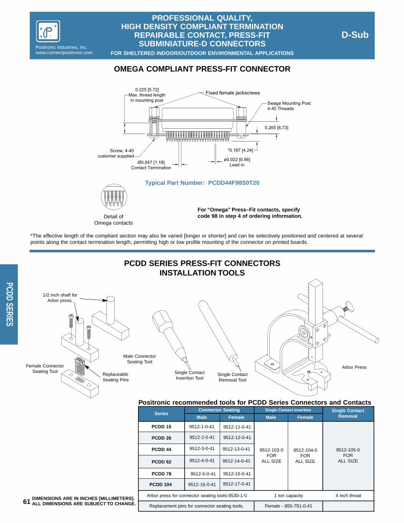
D-Sub
PROFESSIONAL QUALITY,HIGH DENSITY COMPLIANT TERMINATION
REPAIRABLE CONTACT, PRESS-FIT SUBMINIATURE-D CONNECTORS
FOR SHELTERED INDOOR/OUTDOOR ENVIRONMENTAL APPLICATIONSPositronic Industries, Inc.www.connectpositronic.com
61
PCDD SERIES
1/2 inch shaft forArbor press.
ReplaceableSeating Pins
Male ConnectorSeating Tool
Female ConnectorSeating Tool Single Contact
Insertion ToolSingle ContactRemoval Tool
Arbor Press
Fixed female jackscrews
0.265 [6.73]
0.225 [5.72]Max. thread lengthin mounting post
Ø0.047 [1.18]Contact Termination
ø0.022 [0.56]Lead in
Screw, 4-40customer supplied
Swage Mounting Post4-40 Threads
*0.167 [4.24]
9512-15-0-41
9512-103-0FOR
ALL SIZE
OMEGA COMPLIANT PRESS-FIT CONNECTOR
For “Omega” Press–Fit contacts, specifycode 98 in step 4 of ordering information.Detail of
Omega contacts
Typical Part Number: PCDD44F98S0T20
Positronic recommended tools for PCDD Series Connectors and ContactsSingle Contact
RemovalSeriesConnector Seating Single Contact Insertion
PCDD 15 9512-1-0-41 9512-11-0-41
PCDD 26 9512-2-0-41 9512-12-0-41
9512-3-0-41 9512-13-0-41
PCDD 78 9512-5-0-41
PCDD 104 9512-16-0-41 9512-17-0-41
Male Female
9512-104-0FOR
ALL SIZE
9512-105-0FOR
ALL SIZEPCDD 62 9512-4-0-41 9512-14-0-41
PCDD 44
Arbor press for connector seating tools-9530-1-0
Replacement pins for connector seating tools, Female - 855-751-0-41
1 ton capacity 4 inch throat
*The effective length of the compliant section may also be varied [longer or shorter] and can be selectively positioned and centered at severalpoints along the contact termination length, permitting high or low profile mounting of the connector on printed boards.
Male Female
PCDD SERIES PRESS-FIT CONNECTORS INSTALLATION TOOLS
DIMENSIONS ARE IN INCHES [MILLIMETERS].ALL DIMENSIONS ARE SUBJECT TO CHANGE.

62DIMENSIONS ARE IN INCHES [MILLIMETERS].ALL DIMENSIONS ARE SUBJECT TO CHANGE.
D-Sub
PROFESSIONAL QUALITY,HIGH DENSITY COMPLIANT TERMINATION
REPAIRABLE CONTACT, PRESS-FIT SUBMINIATURE-D CONNECTORS
FOR SHELTERED INDOOR/OUTDOOR ENVIRONMENTAL APPLICATIONSPositronic Industries, Inc.
www.connectpositronic.com
PCDD
SER
IES
0.984 [24.99]
0.492 [12.50] 0.190 [4.83]
0.090 [2.29] Typ.
0.078 [1.98]
0.078 [1.98]
1.312 [33.32]
0.656 [16.66]
0.090 [2.29] Typ.
0.380 [9.65]
0.078 [1.98]
0.078 [1.98]
0.078 [1.98]
0.078 [1.98]
0.078 [1.98]
0.078 [1.98]
0.082 [2.08]
0.082 [2.08]
0.082 [2.08]
1.852 [47.04]
0.926 [23.52] 0.650 [16.51]
0.090 [2.29] Typ.
2.500 [63.50]
1.250 [31.75] 0.973 [24.71]
0.095 [2.41] Typ.
2.406 [61.11]
1.203 [30.56] 0.903 [22.94]
0.041[1.04]
0.095 [2.41] Typ.
2.500 [63.50]
1.250 [31.75] 0.981 [24.92]
0.095 [2.41] Typ.
0.975 [24.77]1.250 [31.75]
2.500 [63.50]
0.082 [2.08]
0.082 [2.08]
0.082 [2.08]
2.500 [63.50]
0.082 [2.08] Typ.0.095 [2.41] Typ.
0.903 [22.94]1.203 [30.56]
2.406 [61.11]
0.095 [2.41] Typ.
0.095 [2.41] Typ.
0.078 [1.98]
0.078 [1.98]
0.078 [1.98]
1.312 [33.32]
1.852 [47.04]
0.078 [1.98]
0.090 [2.29] Typ.
0.984 [24.99]
0.090 [2.29] Typ.
0.078 [1.98]
0.078 [1.98]
0.090 [2.29] Typ.
0.492 [12.50] 0.215 [5.46]
0.926 [23.52] 0.655 [16.64]
0.078 [1.98]
0.078 [1.98]
0.082
0.656 [16.66] 0.385 [9.78]
1.250 [31.75] 0.967 [24.56]
0.041[1.04]
[2.08] Typ.
COMPLIANT PRESS-FIT CONNECTOR PRINTED BOARDCONTACT HOLE PATTERN
PCDD 15 MALE
PCDD 44 MALE
PCDD 26 MALE
PCDD 62 MALE
PCDD 78 MALE
PCDD 104 MALE
PCDD 15 FEMALE
PCDD 44 FEMALE
PCDD 26 FEMALE
PCDD 62 FEMALE
PCDD 78 FEMALE
PCDD 104 FEMALE
Ø0.0394+0.0035-0.0024[1.000+0.090-0.060]Finished Hole
Ø0.0453±0.0010[1.150±0.025]
Drilled Hole
0.0005 [15µ] MinimumTin or Tin-Lead
Plate Thickness
0.0010 [25µ] MinimumCopper Plate Thickness
CONTACT HOLE DIAMETERS
Note: For other PCB plating compositions,i.e. ENIG, (Electroless Nickel, ImmersionGold), consult Technical Sales.

D-Sub
PROFESSIONAL QUALITY,HIGH DENSITY COMPLIANT TERMINATION
REPAIRABLE CONTACT, PRESS-FIT SUBMINIATURE-D CONNECTORS
FOR SHELTERED INDOOR/OUTDOOR ENVIRONMENTAL APPLICATIONSPositronic Industries, Inc.www.connectpositronic.com
63 DIMENSIONS ARE IN INCHES [MILLIMETERS].ALL DIMENSIONS ARE SUBJECT TO CHANGE.
PCDD SERIES
4804-249-0-*
STEP
STEP 1 - Basic SeriesPCDD Series
STEP 2 - PCDD Series Connector Variants15, 26, 44, 62, 78, 104
STEP 3 - Connector GenderM - Male F - FemaleFC - Female, Closed Entry
STEP 4 - Type of Contacts98 - Omega type compliant.
STEP 7 - Locking and Polarizing Systems0 - None.V3 - Lock Tab.T6 - Fixed Male and Female Polarized Jackscrews.T2 - Fixed Female Jackscrews, 4-40 Thread.Note: These options must be ordered with connector andcannot be ordered separately.
STEP 6 - Hoods0 - None
STEP 8 - Shell Options0 - Zinc Plated with Dichromate Seal.X - Tin Plated.Z - Tin Plated and Dimpled.
STEP 5 - Mounting StyleS - Swaged Mounting Post 4-40 Threads
0.265 [6,73] Length.
STEP 9 - Special OptionsConsult Sales Department.
ORDERING INFORMATION – CODE NUMBERING SYSTEM
Specify Complete Connector By Following Steps 1 Through 9Insert “0” When Step Is Not Used
91 2 3 4 5 6
PCDD 26 M 98 S 0 T2
7
X
8
MALE OPEN ENTRY FEMALE CLOSED ENTRY FEMALE
4803-21-0-* 4804-25-0-*
* - PLATING OPTIONS FOR REPLACEMENT CONTACTS-14 GOLD 0.000030 [0.76 MICRONS] OVER NICKEL PLATE-51 GOLD FLASH OVER NICKEL PLATE
REPLACEMENT CONTACTS PART NUMBERS

64
D-SubPositronic Industries, Inc.
www.connectpositronic.com
MIL
LIST
INGS
MILITARY REFERENCEPART NUMBER NUMBER*
MILITARY REFERENCEPART NUMBER NUMBER*
MILITARY REFERENCEPART NUMBER NUMBER*
MILITARY REFERENCEPART NUMBER NUMBER*
Positronic Industries offers the following listing of connectors and connector accessories, which are products qualified under Military SpecificationMIL-DTL-24308, MIL-C-39029 and MIL-C-85049. For additional Q.P.L. connectors, please consult the factory sales office.
M24308/1-1 HDC9F20000-50
M24308/1-1F HDC9F2000C-50
M24308/1-2 HDC15F20000-50
M24308/1-2F HDC15F2000C-50
M24308/1-3 HDC25F20000-50
M24308/1-3F HDC25F2000C-50
M24308/1-4 HDC37F20000-50
M24308/1-4F HDC37F2000C-50
M24308/1-5 HDC50F20000-50
M24308/1-5F HDC50F2000C-50
M24308/1-23 HDC9F2F000-50
M24308/1-23F HDC9F2F00C-50
M24308/1-24 HDC15F2F000-50
M24308/1-24F HDC15F2F00C-50
M24308/1-25 HDC25F2F000-50
M24308/1-25F HDC25F2F00C-50
M24308/1-26 HDC37F2F000-50
M24308/1-26F HDC37F2F00C-50
M24308/1-27 HDC50F2F000-50
M24308/1-27F HDC50F2F00C-50
M24308/1-34 HDC9F20000-50-799.0
M24308/1-35 HDC15F20000-50-799.0
M24308/1-36 HDC25F20000-50-799.0
M24308/1-37 HDC37F20000-50-799.0
M24308/1-38 HDC50F20000-50-799.0
M24308/1-56 HDC9F2F000-50-799.2
M24308/1-57 HDC15F2F000-50-799.2
M24308/1-58 HDC25F2F000-50-799.2
M24308/1-59 HDC37F2F000-50-799.2
M24308/1-60 HDC50F2F000-50-799.2
M24308/2-1 RD9F10000-50
M24308/2-1F RD9F1000C-50
M24308/2-2 RD15F10000-50
M24308/2-2F RD15F1000C-50
M24308/2-3 RD25F10000-50
M24308/2-3F RD25F1000C-50
M24308/2-4 RD37F10000-50
M24308/2-4F RD37F1000C-50
M24308/2-5 RD50F10000-50
M24308/2-5F RD50F1000C-50
M24308/2-6 RD9F10000-50-400.0
M24308/2-6F RD9F1000C-50-400.0
M24308/2-7 RD15F10000-50-400.0
M24308/2-7F RD15F1000C-50-400.0
M24308/2-8 RD25F10000-50-400.0
M24308/2-8F RD25F1000C-50-400.0
M24308/2-9 RD37F10000-50-400.0
M24308/2-9F RD37F1000C-50-400.0
M24308/2-10 RD50F10000-50-400.0
M24308/2-10F RD50F1000C-50-400.0
M24308/2-11 DD15F10000-50
M24308/2-11F DD15F1000C-50
M24308/2-12 DD26F10000-50
M24308/2-12F DD26F1000C-50
M24308/2-13 DD44F10000-50
M24308/2-13F DD44F1000C-50
M24308/2-14 DD62F10000-50
M24308/2-14F DD62F1000C-50
M24308/2-15 DD78F10000-50
M24308/2-15F DD78F1000C-50
M24308/2-16 DD104F10000-50
M24308/2-16F DD104F1000C-50
M24308/2-17 DD15F10000-50-400.1
M24308/2-17F DD15F1000C-50-400.1
M24308/2-18 DD26F10000-50-400.1
M24308/2-18F DD26F1000C-50-400.1
M24308/2-19 DD44F10000-50-400.1
M24308/2-19F DD44F1000C-50-400.1
M24308/2-20 DD62F10000-50-400.1
M24308/2-20F DD62F1000C-50-400.1
M24308/2-21 DD78F10000-50-400.1
M24308/2-21F DD78F1000C-50-400.1
M24308/2-22 DD104F10000-50-400.1
M24308/2-22F DD104F1000C-50-400.1
M24308/2-281 RD9F00000
M24308/2-281F RD9F0000C
M24308/2-282 RD15F00000
M24308/2-282F RD15F0000C
M24308/2-283 RD25F00000
M24308/2-283F RD25F0000C
M24308/2-284 RD37F00000
M24308/2-284F RD37F0000C
M24308/2-285 RD50F00000
M24308/2-285F RD50F0000C
M24308/2-286 DD15F00000
M24308/2-286F DD15F0000C
M24308/2-287 DD26F00000
M24308/2-287F DD26F0000C
M24308/2-288 DD44F00000
M24308/2-288F DD44F0000C
M24308/2-289 DD62F00000
M24308/2-289F DD62F0000C
M24308/2-290 DD78F00000
M24308/2-290F DD78F0000C
M24308/2-291 DD104F00000
M24308/2-291F DD104F0000C
M24308/2-342 RD9F1F000-50
M24308/2-342F RD9F1F00C-50
M24308/2-343 RD15F1F000-50
M24308/2-343F RD15F1F00C-50
M24308/2-344 RD25F1F000-50
M24308/2-344F RD25F1F00C-50
M24308/2-345 RD37F1F000-50
M24308/2-345F RD37F1F00C-50
M24308/2-346 RD50F1F000-50
M24308/2-346F RD50F1F00C-50
M24308/2-347 DD15F1F000-50
M24308/2-347F DD15F1F00C-50
M24308/2-348 DD26F1F000-50
M24308/2-348F DD26F1F00C-50
M24308/2-349 DD44F1F000-50
M24308/2-349F DD44F1F00C-50
M24308/2-350 DD62F1F000-50
M24308/2-350F DD62F1F00C-50
M24308/2-351 DD78F1F000-50
M24308/2-351F DD78F1F00C-50
M24308/2-352 DD104F1F000-50
M24308/2-352F DD104F1F00C-50
M24308/2-353 RD9F1F000-50-400.0
M24308/2-353F RD9F1F00C-50-400.0
M24308/2-354 RD15F1F000-50-400.0
M24308/2-354F RD15F1F00C-50-400.0
M24308/2-355 RD25F1F000-50-400.0
M24308/2-355F RD25F1F00C-50-400.0
M24308/2-356 RD37F1F000-50-400.0
M24308/2-356F RD37F1F00C-50-400.0
M24308/2-357 RD50F1F000-50-400.0
M24308/2-357F RD50F1F00C-50-400.0
M24308/2-358 DD15F1F000-50-400.1
M24308/2-358F DD15F1F00C-50-400.1
M24308/2-359 DD26F1F000-50-400.1
M24308/2-359F DD26F1F00C-50-400.1
M24308/2-360 DD44F1F000-50-400.1
M24308/2-360F DD44F1F00C-50-400.1
M24308/2-361 DD62F1F000-50-400.1
M24308/2-361F DD62F1F00C-50-400.1
M24308/2-362 DD78F1F000-50-400.1
M24308/2-362F DD78F1F00C-50-400.1
M24308/2-363 DD104F1F000-50-400.1
M24308/2-363F DD104F1F00C-50-400.1
M24308/2-482 RD9F0F000
M24308/2-482F RD9F0F00C
M24308/2-483 RD15F0F000
M24308/2-483F RD15F0F00C
M24308/2-484 RD25F0F000
M24308/2-484F RD25F0F00C
M24308/2-485 RD37F0F000
M24308/2-485F RD37F0F00C
M24308/2-486 RD50F0F000
M24308/2-486F RD50F0F00C
M24308/2-487 DD15F0F000
M24308/2-487F DD15F0F00C
M24308/2-488 DD26F0F000
M24308/2-488F DD26F0F00C
M24308/2-489 DD44F0F000
M24308/2-489F DD44F0F00C
M24308/2-490 DD62F0F000
M24308/2-490F DD62F0F00C
M24308/2-491 DD78F0F000
M24308/2-491F DD78F0F00C
M24308/2-492 DD104F0F000
M24308/2-492F DD104F0F00C
M24308/2-516 RD9F10000-50-799.0
M24308/2-517 RD15F10000-50-799.0
M24308/2-518 RD25F10000-50-799.0
M24308/2-519 RD37F10000-50-799.0
M24308/2-520 RD50F10000-50-799.0
M24308/2-521 RD9F10000-50-799.1
M24308/2-522 RD15F10000-50-799.1
M24308/2-523 RD25F10000-50-799.1
M24308/2-524 RD37F10000-50-799.1
M24308/2-525 RD50F10000-50-799.1
M24308/2-526 DD15F10000-50-799.0
M24308/2-527 DD26F10000-50-799.0
M24308/2-528 DD44F10000-50-799.0
M24308/2-529 DD62F10000-50-799.0
M24308/2-530 DD78F10000-50-799.0
M24308/2-531 DD104F10000-50-799.0
M24308/2-532 DD15F10000-50-799.1
M24308/2-533 DD26F10000-50-799.1
M24308/2-534 DD44F10000-50-799.1
M24308/2-535 DD62F10000-50-799.1
M24308/2-536 DD78F10000-50-799.1
M24308/2-537 DD104F10000-50-799.1
M24308/2-560 RD9F00000-799.0
M24308/2-561 RD15F00000-799.0
M24308/2-562 RD25F00000-799.0
M24308/2-563 RD37F00000-799.0
M24308/2-564 RD50F00000-799.0
M24308/2-565 DD15F00000-799.0
M24308/2-566 DD26F00000-799.0
M24308/2-567 DD44F00000-799.0
M24308/2-568 DD62F00000-799.0
M24308/2-569 DD78F00000-799.0
M24308/2-570 DD104F00000-799.0
M24308/2-585 RD9F1F000-50-799.2
M24308/2-586 RD15F1F000-50-799.2
M24308/2-587 RD25F1F000-50-799.2
M24308/2-588 RD37F1F000-50-799.2
M24308/2-589 RD50F1F000-50-799.2
M24308/2-590 DD15F1F000-50-799.2
M24308/2-591 DD26F1F000-50-799.2
M24308/2-592 DD44F1F000-50-799.2
M24038/2-593 DD62F1F000-50-799.2
M24308/2-594 DD78F1F000-50-799.2
M24308/2-595 DD104F1F000-50-799.2
M24308/2-596 RD9F1F000-50-799.3
M24308/2-597 RD15F1F000-50-799.3
M24308/2-598 RD25F1F000-50-799.3
M24308/2-599 RD37F1F000-50-799.3
M24308/2-600 RD50F1F000-50-799.3
M24308/2-601 DD15F1F000-50-799.3
M24308/2-602 DD26F1F000-50-799.3
M24308/2-603 DD44F1F000-50-799.3
M24308/2-604 DD62F1F000-50-799.3
M24308/2-605 DD78F1F000-50-799.3
M24308/2-606 DD104F1F000-50-799.3
M24308/2-607 RD9F0F000-799.2
M24308/2-608 RD15F0F000-799.2
M24308/2-609 RD25F0F000-799.2
M24308/2-610 RD37F0F000-799.2
M24308/2-611 RD50F0F000-799.2
M24308/2-612 DD15F0F000-799.2
M24308/2-613 DD26F0F000-799.2
M24308/2-614 DD44F0F000-799.2
M24308/2-615 DD62F0F000-799.2
M24308/2-616 DD78F0F000-799.2
M24308/2-617 DD104F0F000-799.2
M24308/3-1 HDC9M20000-50
M24308/3-1F HDC9M2000C-50
M24308/3-2 HDC15M20000-50
M24308/3-2F HDC15M2000C-50
M24308/3-3 HDC25M20000-50
M24308/3-3F HDC25M2000C-50
M24308/3-4 HDC37M20000-50
M24308/3-4F HDC37M2000C-50
M24308/3-5 HDC50M20000-50
M24308/3-5F HDC50M2000C-50
M24308/3-12 HDC9M2F000-50
M24308/3-12F HDC9M2F00C-50
MIL-DTL-24308 / MIL-C-39029 / MIL-C-85049QUALIFIED PRODUCTS LISTING
*NOTE: Par ts are to be ordered to the mi l i tary number,the Positronic par t number is for reference only .

D-SubMIL-DTL-24308 / MIL-C-39029 / MIL-C-85049
QUALIFIED PRODUCTS LISTING*NOTE: Par ts are to be ordered to the mi l i tary number,
the Positronic par t number is for reference only .Positronic Industries, Inc.www.connectpositronic.com
65
MIL LISTINGS
MILITARY REFERENCEPART NUMBER NUMBER*
MILITARY REFERENCEPART NUMBER NUMBER*
MILITARY REFERENCEPART NUMBER NUMBER*
MILITARY REFERENCEPART NUMBER NUMBER*
M24308/3-13 HDC15M2F000-50
M24308/3-13F HDC15M2F00C-50
M24308/3-14 HDC25M2F000-50
M24308/3-14F HDC25M2F00C-50
M24308/3-15 HDC37M2F000-50
M24308/3-15F HDC37M2F00C-50
M24308/3-16 HDC50M2F000-50
M24308/3-16F HDC50M2F00C-50
M24308/3-17 HDC9M2F000-50
M24308/3-17F HDC9M2F00C-50
M24308/3-18 HDC15M2F000-50
M24308/3-18F HDC15M2F00C-50
M24308/3-19 HDC25M2F000-50
M24308/3-19F HDC25M2F00C-50
M24308/3-20 HDC37M2F000-50
M24308/3-20F HDC37M2F00C-50
M24308/3-21 HDC50M2F000-50
M24308/3-21F HDC50M2F00C-50
M24308/3-23 HDC9M20000-50-799.0
M24308/3-24 HDC15M20000-50-799.0
M24308/3-25 HDC25M20000-50-799.0
M24308/3-26 HDC37M20000-50-799.0
M24308/3-27 HDC50M20000-50-799.0
M24308/3-39 HDC9M2F000-50-799.2
M24308/3-40 HDC15M2F000-50-799.2
M24308/3-41 HDC25M2F000-50-799.2
M24308/3-42 HDC37M2F000-50-799.2
M24308/3-43 HDC50M2F000-50-799.2
M24308/4-1 RD9M10000-50
M24308/4-1F RD9M1000C-50
M24308/4-2 RD15M10000-50
M24308/4-2F RD15M1000C-50
M24308/4-3 RD25M10000-50
M24308/4-3F RD25M1000C-50
M24308/4-4 RD37M10000-50
M24308/4-4F RD37M1000C-50
M24308/4-5 RD50M10000-50
M24308/4-5F RD50M1000C-50
M24308/4-6 RD9M10000-50-400.0
M24308/4-6F RD9M1000C-50-400.0
M24308/4-7 RD15M10000-50-400.0
M24308/4-7F RD15M1000C-50-400.0
M24308/4-8 RD25M10000-50-400.0
M24308/4-8F RD25M1000C-50-400.0
M24308/4-9 RD37M10000-50-400.0
M24308/4-9F RD37M1000C-50-400.0
M24308/4-10 RD50M10000-50-400.0
M24308/4-10F RD50M1000C-50-400.0
M24308/4-11 DD15M10000-50
M24308/4-11F DD15M1000C-50
M24308/4-12 DD26M10000-50
M24308/4-12F DD26M1000C-50
M24308/4-13 DD44M10000-50
M24308/4-13F DD44M1000C-50
M24308/4-14 DD62M10000-50
M24308/4-14F DD62M1000C-50
M24308/4-15 DD78M10000-50
M24308/4-15F DD78M1000C-50
M24308/4-16 DD104M10000-50
M24308/4-16F DD104M1000C-50
M24308/4-17 DD15M10000-50-400.1
M24308/4-17F DD15M1000C-50-400.1
M24308/4-18 DD26M10000-50-400.1
M24308/4-18F DD26M1000C-50-400.1
M24308/4-19 DD44M10000-50-400.1
M24308/4-19F DD44M1000C-50-400.1
M24308/4-20 DD62M10000-50-400.1
M24308/4-20F DD62M1000C-50-400.1
M24308/4-21 DD78M10000-50-400.1
M24308/4-21F DD78M1000C-50-400.1
M24308/4-22 DD104M10000-50-400.1
M24308/4-22F DD104M1000C-50-400.1
M24308/4-259 RD9M00000
M24308/4-259F RD9M0000C
M24308/4-260 RD15M00000
M24308/4-260F RD15M0000C
M24308/4-261 RD25M00000
M24308/4-261F RD25M0000C
M24308/4-262 RD37M00000
M24308/4-262F RD37M0000C
M24308/4-263 RD50M00000
M24308/4-263F RD50M0000C
M24308/4-264 DD15M00000
M24308/4-264F DD15M0000C
M24308/4-265 DD26M00000
M24308/4-265F DD26M0000C
M24308/4-266 DD44M00000
M24308/4-266F DD44M0000C
M24308/4-267 DD62M00000
M24308/4-267F DD62M0000C
M24308/4-268 DD78M00000
M24308/4-268F DD78M0000C
M24308/4-269 DD104M00000
M24308/4-269F DD104M0000C
M24308/4-302 RD9M1F000-50
M24308/4-302F RD9M1F00C-50
M24308/4-303 RD15M1F000-50
M24308/4-303F RD15M1F00C-50
M24308/4-304 RD25M1F000-50
M24308/4-304F RD25M1F00C-50
M24308/4-305 RD37M1F000-50
M24308/4-305F RD37M1F00C-50
M24308/4-306 RD50M1F000-50
M24308/4-306F RD50M1F00C-50
M24308/4-313 RD9M1F000-50-400.0
M24308/4-313F RD9M1F00C-50-400.0
M24308/4-314 RD15M1F000-50-400.0
M24308/4-314F RD15M1F00C-50-400.0
M24308/4-315 RD25M1F000-50-400.0
M24308/4-315F RD25M1F00C-50-400.0
M24308/4-316 RD37M1F000-50-400.0
M24308/4-316F RD37M1F00C-50-400.0
M24308/4-317 RD50M1F000-50-400.0
M24308/4-317F RD50M1F00C-50-400.0
M24308/4-324 RD9M0F000
M24308/4-324F RD9M0F00C
M24308/4-325 RD15M0F000
M24308/4-325F RD15M0F00C
M24308/4-326 RD25M0F000
M24308/4-326F RD25M0F00C
M24308/4-327 RD37M0F000
M24308/4-327F RD37M0F00C
M24308/4-328 RD50M0F000
M24308/4-328F RD50M0F00C
M24308/4-335 RD9M10000-50-799.0
M24308/4-336 RD15M10000-50-799.0
M24308/4-337 RD25M10000-50-799.0
M24308/4-338 RD37M10000-50-799.0
M24308/4-339 RD50M10000-50-799.0
M24308/4-340 RD9M10000-50-799.1
M24308/4-341 RD15M10000-50-799.1
M24308/4-342 RD25M10000-50-799.1
M24308/4-343 RD37M10000-50-799.1
M24308/4-344 RD50M10000-50-799.1
M24308/4-345 DD15M10000-50-799.0
M24308/4-346 DD26M10000-50-799.0
M24308/4-347 DD44M10000-50-799.0
M24308/4-348 DD62M10000-50-799.0
M24308/4-349 DD78M10000-50-799.0
M24308/4-350 DD104M10000-50-799.0
M24308/4-351 DD15M10000-50-799.1
M24308/4-352 DD26M10000-50-799.1
M24308/4-353 DD44M10000-50-799.1
M24308/4-354 DD62M10000-50-799.1
M24308/4-355 DD78M10000-50-799.1
M24308/4-356 DD104M10000-50-799.1
M24308/4-357 RD9M00000-799.0
M24308/4-358 RD15M00000-799.0
M24308/4-359 RD25M00000-799.0
M24308/4-360 RD37M00000-799.0
M24308/4-361 RD50M00000-799.0
M24308/4-362 DD15M00000-799.0
M24308/4-363 DD26M00000-799.0
M24308/4-364 DD44M00000-799.0
M24308/4-365 DD62M00000-799.0
M24308/4-366 DD78M00000-799.0
M24308/4-367 DD104M00000-799.0
M24308/4-401 RD9M1F000-50-799.2
M24308/4-402 RD15M1F000-50-799.2
M24308/4-403 RD25M1F000-50-799.2
M24308/4-404 RD37M1F000-50-799.2
M24308/4-405 RD50M1F000-50-799.2
M24308/4-406 DD15M1F000-50-799.2
M24308/4-407 DD26M1F000-50-799.2
M24308/4-408 DD44M1F000-50-799.2
M24308/4-409 DD62M1F000-50-799.2
M24308/4-410 DD78M1F000-50-799.2
M24308/4-411 DD104M1F000-50-799.2
M24308/4-412 RD9M1F000-50-799.3
M24308/4-413 RD15M1F000-50-799.3
M24308/4-414 RD25M1F000-50-799.3
M24308/4-415 RD37M1F000-50-799.3
M24308/4-416 RD50M1F000-50-799.3
M24308/4-417 DD15M1F000-50-799.3
M24308/4-418 DD26M1F000-50-799.3
M24308/4-419 DD44M1F000-50-799.3
M24308/4-420 DD62M1F000-50-799.3
M24308/4-421 DD78M1F000-50-799.3
M24308/4-422 DD104M1F000-50-799.3
M24308/4-423 RD9M0F000-799.2
M24308/4-424 RD15M0F000-799.2
M24308/4-425 RD25M0F000-799.2
M24308/4-426 RD37M0F000-799.2
M24308/4-427 RD50M0F000-799.2
M24308/4-428 DD15M0F000-799.2
M24308/4-429 DD26M0F000-799.2
M24308/4-430 DD44M0F000-799.2
M24308/4-431 DD62M0F000-799.2
M24308/4-432 DD78M0F000-799.2
M24308/4-433 DD104M0F000-799.2
M24308/4-435 RD9M1F000-50
M24308/4-435F RD9M1F00C-50
M24308/4-436 RD15M1F000-50
M24308/4-436F RD15M1F00C-50
M24308/4-437 RD25M1F000-50
M24308/4-437F RD25M1F00C-50
M24308/4-438 RD37M1F000-50
M24308/4-438F RD37M1F00C-50
M24308/4-439 RD50M1F000-50
M24308/4-439F RD50M1F00C-50
M24308/4-440 DD15M10000-50
M24308/4-440F DD15M1000C-50
M24308/4-441 DD26M10000-50
M24308/4-441F DD26M1000C-50
M24308/4-442 DD44M10000-50
M24308/4-442F DD44M1000C-50
M24308/4-443 DD62M10000-50
M24308/4-443F DD62M1000C-50
M24308/4-444 DD78M10000-50
M24308/4-444F DD78M1000C-50
M24308/4-445 DD104M10000-50
M24308/4-445F DD104M1000C-50
M24308/4-446 RD9M1F000-50-400.0
M24308/4-446F RD9M1F00C-50-400.0
M24308/4-447 RD15M1F000-50-400.0
M24308/4-447F RD15M1F00C-50-400.0
M24308/4-448 RD25M1F000-50-400.0
M24308/4-448F RD25M1F00C-50-400.0
M24308/4-449 RD37M1F000-50-400.0
M24308/4-449F RD37M1F00C-50-400.0
M24308/4-450 RD50M1F000-50-400.0
M24308/4-450F RD50M1F00C-50-400.0
M24308/4-451 DD15M1F000-50-400.1
M24308/4-451F DD15M1F00C-50-400.1
M24308/4-452 DD26M1F000-50-400.1
M24308/4-452F DD26M1F00C-50-400.1
M24308/4-453 DD44M1F000-50-400.1
M24308/4-453F DD44M1F00C-50-400.1
Positronic HDC Series connectors are Q.P.L. approved to MIL-DTL-24308 per test report number 24308-618-79/24308-1210-85.Positronic RD Series hoods are Q.P.L. approved to MIL-C-85049 per test report number 85049-870-84.Positronic DD Series connectors are Q.P.L. approved to MIL-DTL-24308 per test report number 24308-1209-85/24308-1210-85/24308-117-89.Positronic RD Series connectors are Q.P.L. approved to MIL-DTL-24308 per test report number 24308-211-79/24308-1210-85.Positronic RD Series contacts are Q.P.L. approved to MIL-C-39029 per test report number 39029-694-79.

MILITARY REFERENCEPART NUMBER NUMBER*
MILITARY REFERENCEPART NUMBER NUMBER*
MILITARY REFERENCEPART NUMBER NUMBER*
MILITARY REFERENCEPART NUMBER NUMBER*
66
D-SubPositronic Industries, Inc.
www.connectpositronic.com
MIL
LIST
INGS
MIL-DTL-24308 / MIL-C-39029 / MIL-C-85049QUALIFIED PRODUCTS LISTING
*NOTE: Par ts are to be ordered to the mi l i tary number,the Positronic par t number is for reference only .
M24308/4-454 DD62M1F000-50-400.1
M24308/4-454F DD62M1F00C-50-400.1
M24308/4-455 DD78M1F000-50-400.1
M24308/4-455F DD78M1F00C-50-400.1
M24308/4-456 DD104M1F000-50-400.1
M24308/4-456F DD104M1F00C-50-400.1
M24308/4-457 RD9M0F000
M24308/4-457F RD9M0F00C
M24308/4-458 RD15M0F000
M24308/4-458F RD15M0F00C
M24308/4-459 RD25M0F000
M24308/4-459F RD25M0F00C
M24308/4-460 RD37M0F000
M24308/4-460F RD37M0F00C
M24308/4-461 RD50M0F000
M24308/4-461F RD50M0F00C
M24308/4-462 DD15M0F000
M24308/4-462F DD15M0F00C
M24308/4-463 DD26M0F000
M24308/4-463F DD26M0F00C
M24308/4-464 DD44M0F000
M24308/4-464F DD44M0F00C
M24308/4-465 DD62M0F000
M24308/4-465F DD62M0F00C
M24308/4-466 DD78M0F000
M24308/4-466F DD78M0F00C
M24308/4-467 DD104M0F000
M24308/4-467F DD104M0F00C
M24308/5-1 HDC9F20000-50-403.0
M24308/5-1F HDC9F2000C-50-403.0
M24308/5-1P HDC9F2000S-50
M24308/5-2 HDC15F20000-50-403.0
M24308/5-2F HDC15F2000C-50-403.0
M24308/5-2P HDC15F2000S-50
M24308/5-3 HDC25F20000-50-403.0
M24308/5-3F HDC25F2000C-50-403.0
M24308/5-3P HDC25F2000S-50
M24308/5-4 HDC37F20000-50-403.0
M24308/5-4F HDC37F2000C-50-403.0
M24308/5-4P HDC37F2000S-50
M24308/5-5 HDC50F20000-50-403.0
M24308/5-5F HDC50F2000C-50-403.0
M24308/5-5P HDC50F2000S-50
M24308/5-23 HDC9F2F000-50-403.0
M24308/5-23F HDC9F2F00C-50-403.0
M24308/5-23P HDC9F2F00S-50
M24308/5-24 HDC15F2F000-50-403.0
M24308/5-24F HDC15F2F00C-50-403.0
M24308/5-24P HDC15F2F00S-50
M24308/5-25 HDC25F2F000-50-403.0
M24308/5-25F HDC25F2F00C-50-403.0
M24308/5-25P HDC25F2F00S-50
M24308/5-26 HDC37F2F000-50-403.0
M24308/5-26F HDC37F2F00C-50-403.0
M24308/5-26P HDC37F2F00S-50
M24308/5-27 HDC50F2F000-50-403.0
M24308/5-27F HDC50F2F00C-50-403.0
M24308/5-27P HDC50F2F00S-50
M24308/5-34 HDC9F20000-50-403.3
M24308/5-35 HDC15F20000-50-403.3
M24308/5-36 HDC25F20000-50-403.3
M24308/5-37 HDC37F20000-50-403.3
M24308/5-38 HDC50F20000-50-403.3
M24308/5-56 HDC9F2F000-50-403.4
M24308/5-57 HDC15F2F000-50-403.4
M24308/5-58 HDC25F2F000-50-403.4
M24308/5-59 HDC37F2F000-50-403.4
M24308/5-60 HDC50F2F000-50-403.4
M24308/6-1 RD9F10000-50-403.0
M24308/6-1F RD9F1000C-50-403.0
M24308/6-1P RD9F1000S-50
M24308/6-2 RD15F10000-50-403.0
M24308/6-2F RD15F1000C-50-403.0
M24308/6-2P RD15F1000S-50
M24308/6-3 RD25F10000-50-403.0
M24308/6-3F RD25F1000C-50-403.0
M24308/6-3P RD25F1000S-50
M24308/6-4 RD37F10000-50-403.0
M24308/6-4F RD37F1000C-50-403.0
M24308/6-4P RD37F1000S-50
M24308/6-5 RD50F10000-50-403.0
M24308/6-5F RD50F1000C-50-403.0
M24308/6-5P RD50F1000S-50
M24308/6-6 RD9F10000-50-403.1
M24308/6-6F RD9F1000C-50-403.1
M24308/6-6P RD9F1000S-50-400.0
M24308/6-7 RD15F10000-50-403.1
M24308/6-7F RD15F1000C-50-403.1
M24308/6-7P RD15F1000S-50-400.0
M24308/6-8 RD25F10000-50-403.1
M24308/6-8F RD25F1000C-50-403.1
M24308/6-8P RD25F1000S-50-400.0
M24308/6-9 RD37F10000-50-403.1
M24308/6-9F RD37F1000C-50-403.1
M24308/6-9P RD37F1000S-50-400.0
M24308/6-10 RD50F10000-50-403.1
M24308/6-10F RD50F1000C-50-403.1
M24308/6-10P RD50F1000S-50-400.0
M24308/6-11 DD15F10000-50-403.0
M24308/6-11F DD15F1000C-50-403.0
M24308/6-11P DD15F1000S-50
M24308/6-12 DD26F10000-50-403.0
M24308/6-12F DD26F1000C-50-403.0
M24308/6-12P DD26F1000S-50
M24308/6-13 DD44F10000-50-403.0
M24308/6-13F DD44F1000C-50-403.0
M24308/6-13P DD44F1000S-50
M24308/6-14 DD62F10000-50-403.0
M24308/6-14F DD62F1000C-50-403.0
M24308/6-14P DD62F1000S-50
M24308/6-15 DD78F10000-50-403.0
M24308/6-15F DD78F1000C-50-403.0
M24308/6-15P DD78F1000S-50
M24308/6-16 DD104F10000-50-403.0
M24308/6-16F DD104F1000C-50-403.0
M24308/6-16P DD104F1000S-50
M24308/6-17 DD15F10000-50-403.2
M24308/6-17F DD15F1000C-50-403.2
M24308/6-17P DD15F1000S-50-400.1
M24308/6-18 DD26F10000-50-403.2
M24308/6-18F DD26F1000C-50-403.2
M24308/6-18P DD26F1000S-50-400.1
M24308/6-19 DD44F10000-50-403.2
M24308/6-19F DD44F1000C-50-403.2
M24308/6-19P DD44F1000S-50-400.1
M24308/6-20 DD62F10000-50-403.2
M24308/6-20F DD62F1000C-50-403.2
M24308/6-20P DD62F1000S-50-400.1
M24308/6-21 DD78F10000-50-403.2
M24308/6-21F DD78F1000C-50-403.2
M24308/6-21P DD78F1000S-50-400.1
M24308/6-22 DD104F10000-50-403.2
M24308/6-22F DD104F1000C-50-403.2
M24308/6-22P DD104F1000S-50-400.1
M24308/6-281 RD9F00000-403.0
M24308/6-281F RD9F0000C-403.0
M24308/6-281P RD9F0000S
M24308/6-282 RD15F00000-403.0
M24308/6-282F RD15F0000C-403.0
M24308/6-282P RD15F0000S
M24308/6-283 RD25F00000-403.0
M24308/6-283F RD25F0000C-403.0
M24308/6-283P RD25F0000S
M24308/6-284 RD37F00000-403.0
M24308/6-284F RD37F0000C-403.0
M24308/6-284P RD37F0000S
M24308/6-285 RD50F00000-403.0
M24308/6-285F RD50F0000C-403.0
M24308/6-285P RD50F0000S
M24308/6-286 DD15F00000-403.0
M24308/6-286F DD15F0000C-403.0
M24308/6-286P DD15F0000S
M24308/6-287 DD26F00000-403.0
M24308/6-287F DD26F0000C-403.0
M24308/6-287P DD26F0000S
M24308/6-288 DD44F00000-403.0
M24308/6-288F DD44F0000C-403.0
M24308/6-288P DD44F0000S
M24308/6-289 DD62F00000-403.0
M24308/6-289F DD62F0000C-403.0
M24308/6-289P DD62F0000S
M24308/6-290 DD78F00000-403.0
M24308/6-290F DD78F0000C-403.0
M24308/6-290P DD78F0000S
M24308/6-291 DD104F00000-403.0
M24308/6-291F DD104F0000C-403.0
M24308/6-291P DD104F0000S
M24308/6-453 RD9F1F000-50-403.0
M24308/6-453F RD9F1F00C-50-403.0
M24308/6-453P RD9F1F00S-50
M24308/6-454 RD15F1F000-50-403.0
M24308/6-454F RD15F1F00C-50-403.0
M24308/6-454P RD15F1F00S-50
M24308/6-455 RD25F1F000-50-403.0
M24308/6-455F RD25F1F00C-50-403.0
M24308/6-455P RD25F1F00S-50
M24308/6-456 RD37F1F000-50-403.0
M24308/6-456F RD37F1F00C-50-403.0
M24308/6-456P RD37F1F00S-50
M24308/6-457 RD50F1F000-50-403.0
M24308/6-457F RD50F1F00C-50-403.0
M24308/6-457P RD50F1F00S-50
M24308/6-458 DD15F1F000-50-403.0
M24308/6-458F DD15F1F00C-50-403.0
M24308/6-458P DD15F1F00S-50
M24308/6-459 DD26F1F000-50-403.0
M24308/6-459F DD26F1F00C-50-403.0
M24308/6-459P DD26F1F00S-50
M24308/6-460 DD44F1F000-50-403.0
M24308/6-460F DD44F1F00C-50-403.0
M24308/6-460P DD44F1F00S-50
M24308/6-461 DD62F1F000-50-403.0
M24308/6-461F DD62F1F00C-50-403.0
M24308/6-461P DD62F1F00S-50
M24308/6-462 DD78F1F000-50-403.0
M24308/6-462F DD78F1F00C-50-403.0
M24308/6-462P DD78F1F00S-50
M24308/6-463 DD104F1F000-50-403.0
M24308/6-463F DD104F1F00C-50-403.0
M24308/6-463P DD104F1F00S-50
M24308/6-464 RD9F1F000-50-403.1
M24308/6-464F RD9F1F00C-50-403.1
M24308/6-464P RD9F1F00S-50-400.0
M24308/6-465 RD15F1F000-50-403.1
M24308/6-465F RD15F1F00C-50-403.1
M24308/6-465P RD15F1F00S-50-400.0
M24308/6-466 RD25F1F000-50-403.1
M24308/6-466F RD25F1F00C-50-403.1
M24308/6-466P RD25F1F00S-50-400.0
M24308/6-467 RD37F1F000-50-403.1
M24308/6-467F RD37F1F00C-50-403.1
M24308/6-467P RD37F1F00S-50-400.0
M24308/6-468 RD50F1F000-50-403.1
M24308/6-468F RD50F1F00C-50-403.1
M24308/6-468P RD50F1F00S-50-400.0
M24308/6-469 DD15F1F000-50-403.2
M24308/6-469F DD15F1F00C-50-403.2
M24308/6-469P DD15F1F00S-50-400.1
M24308/6-470 DD26F1F000-50-403.2
M24308/6-470F DD26F1F00C-50-403.2
M24308/6-470P DD26F1F00S-50-400.1
M24308/6-471 DD44F1F000-50-403.2
M24308/6-471F DD44F1F00C-50-403.2
M24308/6-471P DD44F1F00S-50-400.1
M24308/6-472 DD62F1F000-50-403.2
M24308/6-472F DD62F1F00C-50-403.2
M24308/6-472P DD62F1F00S-50-400.1
M24308/6-473 DD78F1F000-50-403.2
Positronic HDC Series connectors are Q.P.L. approved to MIL-DTL-24308 per test report number 24308-618-79/24308-1210-85.Positronic RD Series hoods are Q.P.L. approved to MIL-C-85049 per test report number 85049-870-84.Positronic DD Series connectors are Q.P.L. approved to MIL-DTL-24308 per test report number 24308-1209-85/24308-1210-85/24308-117-89.Positronic RD Series connectors are Q.P.L. approved to MIL-DTL-24308 per test report number 24308-211-79/24308-1210-85.Positronic RD Series contacts are Q.P.L. approved to MIL-C-39029 per test report number 39029-694-79.

D-SubMIL-DTL-24308 / MIL-C-39029 / MIL-C-85049
QUALIFIED PRODUCTS LISTING*NOTE: Par ts are to be ordered to the mi l i tary number,
the Positronic par t number is for reference only .Positronic Industries, Inc.www.connectpositronic.com
67
MIL LISTINGS
Positronic HDC Series connectors are Q.P.L. approved to MIL-DTL-24308 per test report number 24308-618-79/24308-1210-85.Positronic RD Series hoods are Q.P.L. approved to MIL-C-85049 per test report number 85049-870-84.Positronic DD Series connectors are Q.P.L. approved to MIL-DTL-24308 per test report number 24308-1209-85/24308-1210-85/24308-117-89.Positronic RD Series connectors are Q.P.L. approved to MIL-DTL-24308 per test report number 24308-211-79/24308-1210-85.Positronic RD Series contacts are Q.P.L. approved to MIL-C-39029 per test report number 39029-694-79.
M24308/6-473F DD78F1F00C-50-403.2
M24308/6-473P DD78F1F00S-50-400.1
M24308/6-474 DD104F1F000-50-403.2
M24308/6-474F DD104F1F00C-50-403.2
M24308/6-474P DD104F1F00S-50-400.1
M24308/6-491 RD9F0F000-403.0
M24308/6-491F RD9F0F00C-403.0
M24308/6-491P RD9F0F00S
M24308/6-492 RD15F0F000-403.0
M24308/6-492F RD15F0F00C-403.0
M24308/6-492P RD15F0F00S
M24308/6-493 RD25F0F000-403.0
M24308/6-493F RD25F0F00C-403.0
M24308/6-493P RD25F0F00S
M24308/6-494 RD37F0F000-403.0
M24308/6-494F RD37F0F00C-403.0
M24308/6-494P RD37F0F00S
M24308/6-495 RD50F0F000-403.0
M24308/6-495F RD50F0F00C-403.0
M24308/6-495P RD50F0F00S
M24308/6-496 DD15F0F000-403.0
M24308/6-496F DD15F0F00C-403.0
M24308/6-496P DD15F0F00S
M24308/6-497 DD26F0F000-403.0
M24308/6-497F DD26F0F00C-403.0
M24308/6-497P DD26F0F00S
M24308/6-498 DD44F0F000-403.0
M24308/6-498F DD44F0F00C-403.0
M24308/6-498P DD44F0F00S
M24308/6-499 DD62F0F000-403.0
M24308/6-499F DD62F0F00C-403.0
M24308/6-499P DD62F0F00S
M24308/6-500 DD78F0F000-403.0
M24308/6-500F DD78F0F00C-403.0
M24308/6-500P DD78F0F00S
M24308/6-501 DD104F0F000-403.0
M24308/6-501F DD104F0F00C-403.0
M24308/6-501P DD104F0F00S
M24308/6-502 RD9F10000-50-403.3
M24308/6-503 RD15F10000-50-403.3
M24308/6-504 RD25F10000-50-403.3
M24308/6-505 RD37F10000-50-403.3
M24308/6-506 RD50F10000-50-403.3
M24308/6-507 RD9F10000-50-403.5
M24308/6-508 RD15F10000-50-403.5
M24308/6-509 RD25F10000-50-403.5
M24308/6-510 RD37F10000-50-403.5
M24308/6-511 RD50F10000-50-403.5
M24308/6-512 DD15F10000-50-403.3
M24308/6-513 DD26F10000-50-403.3
M24308/6-514 DD44F10000-50-403.3
M24308/6-515 DD62F10000-50-403.3
M24308/6-516 DD78F10000-50-403.3
M24308/6-517 DD104F10000-50-403.3
M24308/6-518 DD15F10000-50-403.5
M24308/6-519 DD26F10000-50-403.5
M24308/6-520 DD44F10000-50-403.5
M24308/6-521 DD62F10000-50-403.5
M24308/6-522 DD78F10000-50-403.5
M24308/6-523 DD104F10000-50-403.5
M24308/6-540 RD9F00000-403.3
M24308/6-541 RD15F00000-403.3
M24308/6-542 RD25F00000-403.3
M24308/6-543 RD37F00000-403.3
M24308/6-544 RD50F00000-403.3
M24308/6-545 DD15F00000-403.3
M24308/6-546 DD26F00000-403.3
M24308/6-547 DD44F00000-403.3
M24308/6-548 DD62F00000-403.3
M24308/6-549 DD78F00000-403.3
M24308/6-550 DD104F00000-403.3
M24308/6-551 RD9F1F000-50-403.4
M24308/6-552 RD15F1F000-50-403.4
M24308/6-553 RD25F1F000-50-403.4
M24308/6-554 RD37F1F000-50-403.4
M24308/6-555 RD50F1F000-50-403.4
M24308/6-556 DD15F1F000-50-403.4
M24308/6-557 DD26F1F000-50-403.4
M24308/6-558 DD44F1F000-50-403.4
M24308/6-559 DD62F1F000-50-403.4
M24308/6-560 DD78F1F000-50-403.4
M24308/6-561 DD104F1F000-50-403.4
M24308/6-562 RD9F1F000-50-403.6
M24308/6-563 RD15F1F000-50-403.6
M24308/6-564 RD25F1F000-50-403.6
M24308/6-565 RD37F1F000-50-403.6
M24308/6-566 RD50F1F000-50-403.6
M24308/6-567 DD15F1F000-50-403.6
M24308/6-568 DD26F1F000-50-403.6
M24308/6-569 DD44F1F000-50-403.6
M24308/6-570 DD62F1F000-50-403.6
M24308/6-571 DD78F1F000-50-403.6
M24308/6-572 DD104F1F000-50-403.6
M24308/6-573 RD9F0F000-403.4
M24308/6-574 RD15F0F000-403.4
M24308/6-575 RD25F0F000-403.4
M24308/6-576 RD37F0F000-403.4
M24308/6-577 RD50F0F000-403.4
M24308/6-578 DD15F0F000-403.4
M24308/6-579 DD26F0F000-403.4
M24308/6-580 DD44F0F000-403.4
M24308/6-581 DD62F0F000-403.4
M24308/6-582 DD78F0F000-403.4
M24308/6-583 DD104F0F000-403.4
M24308/7-1 HDC9M20000-50-403.0
M24308/7-1F HDC9M2000C-50-403.0
M24308/7-1P HDC9M2000S-50
M24308/7-2 HDC15M20000-50-403.0
M24308/7-2F HDC15M2000C-50-403.0
M24308/7-2P HDC15M2000S-50
M24308/7-3 HDC25M20000-50-403.0
M24308/7-3F HDC25M2000C-50-403.0
M24308/7-3P HDC25M2000S-50
M24308/7-4 HDC37M20000-50-403.0
M24308/7-4F HDC37M2000C-50-403.0
M24308/7-4P HDC37M2000S-50
M24308/7-5 HDC50M20000-50-403.0
M24308/7-5F HDC50M2000C-50-403.0
M24308/7-5P HDC50M2000S-50
M24308/7-12 HDC9M2F000-50-403.0
M24308/7-12F HDC9M2F00C-50-403.0
M24308/7-12P HDC9M2F00S-50
M24308/7-13 HDC15M2F000-50-403.0
M24308/7-13F HDC15M2F00C-50-403.0
M24308/7-13P HDC15M2F00S-50
M24308/7-14 HDC25M2F000-50-403.0
M24308/7-14F HDC25M2F00C-50-403.0
M24308/7-14P HDC25M2F00S-50
M24308/7-15 HDC37M2F000-50-403.0
M24308/7-15F HDC37M2F00C-50-403.0
M24308/7-15P HDC37M2F00S-50
M24308/7-16 HDC50M2F000-50-403.0
M24308/7-16F HDC50M2F00C-50-403.0
M24308/7-16P HDC50M2F00S-50
M24308/7-17 HDC9M2F000-50-403.0
M24308/7-17F HDC9M2F00C-50-403.0
M24308/7-17P HDC9M2F00S-50
M24308/7-18 HDC15M2F000-50-403.0
M24308/7-18F HDC15M2F00C-50-403.0
M24308/7-18P HDC15M2F00S-50
M24308/7-19 HDC25M2F000-50-403.0
M24308/7-19F HDC25M2F00C-50-403.0
M24308/7-19P HDC25M2F00S-50
M24308/7-20 HDC37M2F000-50-403.0
M24308/7-20F HDC37M2F00C-50-403.0
M24308/7-20P HDC37M2F00S-50
M24308/7-21 HDC50M2F000-50-403.0
M24308/7-21F HDC50M2F00C-50-403.0
M24308/7-21P HDC50M2F00S-50
M24308/7-23 HDC9M20000-50-403.3
M24308/7-24 HDC15M20000-50-403.3
M24308/7-25 HDC25M20000-50-403.3
M24308/7-26 HDC37M20000-50-403.3
M24308/7-27 HDC50M20000-50-403.3
M24308/7-34 HDC9M2F000-50-403.4
M24308/7-35 HDC15M2F000-50-403.4
M24308/7-36 HDC25M2F000-50-403.4
M24308/7-37 HDC37M2F000-50-403.4
M24308/7-38 HDC50M2F000-50-403.4
M24308/8-1 RD9M10000-50-403.0
M24308/8-1F RD9M1000C-50-403.0
M24308/8-1P RD9M1000S-50
M24308/8-2 RD15M10000-50-403.0
M24308/8-2F RD15M1000C-50-403.0
M24308/8-2P RD15M1000S-50
M24308/8-3 RD25M10000-50-403.0
M24308/8-3F RD25M1000C-50-403.0
M24308/8-3P RD25M1000S-50
M24308/8-4 RD37M10000-50-403.0
M24308/8-4F RD37M1000C-50-403.0
M24308/8-4P RD37M1000S-50
M24308/8-5 RD50M10000-50-403.0
M24308/8-5F RD50M1000C-50-403.0
M24308/8-5P RD50M1000S-50
M24308/8-6 RD9M10000-50-403.1
M24308/8-6F RD9M1000C-50-403.1
M24308/8-6P RD9M1000S-50-400.0
M24308/8-7 RD15M10000-50-403.1
M24308/8-7F RD15M1000C-50-403.1
M24308/8-7P RD15M1000S-50-400.0
M24308/8-8 RD25M10000-50-403.1
M24308/8-8F RD25M1000C-50-403.1
M24308/8-8P RD25M1000S-50-400.0
M24308/8-9 RD37M10000-50-403.1
M24308/8-9F RD37M1000C-50-403.1
M24308/8-9P RD37M1000S-50-400.0
M24308/8-10 RD50M10000-50-403.1
M24308/8-10F RD50M1000C-50-403.1
M24308/8-10P RD50M1000S-50-400.0
M24308/8-11 DD15M10000-50-403.0
M24308/8-11F DD15M1000C-50-403.0
M24308/8-11P DD15M1000S-50
M24308/8-12 DD26M10000-50-403.0
M24308/8-12F DD26M1000C-50-403.0
M24308/8-12P DD26M1000S-50
M24308/8-13 DD44M10000-50-403.0
M24308/8-13F DD44M1000C-50-403.0
M24308/8-13P DD44M1000S-50
M24308/8-14 DD62M10000-50-403.0
M24308/8-14F DD62M1000C-50-403.0
M24308/8-14P DD62M1000S-50
M24308/8-15 DD78M10000-50-403.0
M24308/8-15F DD78M1000C-50-403.0
M24308/8-15P DD78M1000S-50
M24308/8-16 DD104M10000-50-403.0
M24308/8-16F DD104M1000C-50-403.0
M24308/8-16P DD104M1000S-50
M24308/8-17 DD15M10000-50-403.2
M24308/8-17F DD15M1000C-50-403.2
M24308/8-17P DD15M1000S-50-400.1
M24308/8-18 DD26M10000-50-403.2
M24308/8-18F DD26M1000C-50-403.2
M24308/8-18P DD26M1000S-50-400.1
M24308/8-19 DD44M10000-50-403.2
M24308/8-19F DD44M1000C-50-403.2
M24308/8-19P DD44M1000S-50-400.1
M24308/8-20 DD62M10000-50-403.2
M24308/8-20F DD62M1000C-50-403.2
M24308/8-20P DD62M1000S-50-400.1
M24308/8-21 DD78M10000-50-403.2
M24308/8-21F DD78M1000C-50-403.2
M24308/8-21P DD78M1000S-50-400.1
M24308/8-22 DD104M10000-50-403.2
M24308/8-22F DD104M1000C-50-403.2
M24308/8-22P DD104M1000S-50-400.1
M24308/8-259 RD9M00000-403.0
M24308/8-259F RD9M0000C-403.0
M24308/8-259P RD9M0000S
MILITARY REFERENCEPART NUMBER NUMBER*
MILITARY REFERENCEPART NUMBER NUMBER*
MILITARY REFERENCEPART NUMBER NUMBER*
MILITARY REFERENCEPART NUMBER NUMBER*

68
D-SubPositronic Industries, Inc.
www.connectpositronic.com
MIL
LIST
INGS
MIL-DTL-24308 / MIL-C-39029 / MIL-C-85049QUALIFIED PRODUCTS LISTING
*NOTE: Par ts are to be ordered to the mi l i tary number,the Positronic par t number is for reference only .
Positronic HDC Series connectors are Q.P.L. approved to MIL-DTL-24308 per test report number 24308-618-79/24308-1210-85.Positronic RD Series hoods are Q.P.L. approved to MIL-C-85049 per test report number 85049-870-84.Positronic DD Series connectors are Q.P.L. approved to MIL-DTL-24308 per test report number 24308-1209-85/24308-1210-85/24308-117-89.Positronic RD Series connectors are Q.P.L. approved to MIL-DTL-24308 per test report number 24308-211-79/24308-1210-85.Positronic RD Series contacts are Q.P.L. approved to MIL-C-39029 per test report number 39029-694-79.
M24308/8-260 RD15M00000-403.0
M24308/8-260F RD15M0000C-403.0
M24308/8-260P RD15M0000S
M24308/8-261 RD25M00000-403.0
M24308/8-261F RD25M0000C-403.0
M24308/8-261P RD25M0000S
M24308/8-262 RD37M00000-403.0
M24308/8-262F RD37M0000C-403.0
M24308/8-262P RD37M0000S
M24308/8-263 RD50M00000-403.0
M24308/8-263F RD50M0000C-403.0
M24308/8-263P RD50M0000S
M24308/8-264 DD15M00000-403.0
M24308/8-264F DD15M0000C-403.0
M24308/8-264P DD15M0000S
M24308/8-265 DD26M00000-403.0
M24308/8-265F DD26M0000C-403.0
M24308/8-265P DD26M0000S
M24308/8-266 DD44M00000-403.0
M24308/8-266F DD44M0000C-403.0
M24308/8-266P DD44M0000S
M24308/8-267 DD62M00000-403.0
M24308/8-267F DD62M0000C-403.0
M24308/8-267P DD62M0000S
M24308/8-268 DD78M00000-403.0
M24308/8-268F DD78M0000C-403.0
M24308/8-268P DD78M0000S
M24308/8-269 DD104M00000-403.0
M24308/8-269F DD104M0000C-403.0
M24308/8-269P DD104M0000S
M24308/8-335 RD9M10000-50-403.3
M24308/8-336 RD15M10000-50-403.3
M24308/8-337 RD25M10000-50-403.3
M24308/8-338 RD37M10000-50-403.3
M24308/8-339 RD50M10000-50-403.3
M24308/8-340 RD9M10000-50-403.5
M24308/8-341 RD15M10000-50-403.5
M24308/8-342 RD25M10000-50-403.5
M24308/8-343 RD37M10000-50-403.5
M24308/8-344 RD50M10000-50-403.5
M24308/8-345 DD15M10000-50-403.3
M24308/8-346 DD26M10000-50-403.3
M24308/8-347 DD44M10000-50-403.3
M24308/8-348 DD62M10000-50-403.3
M24308/8-349 DD78M10000-50-403.3
M24308/8-350 DD104M10000-50-403.3
M24308/8-351 DD15M10000-50-403.5
M24308/8-352 DD26M10000-50-403.5
M24308/8-353 DD44M10000-50-403.5
M24308/8-354 DD62M10000-50-403.5
M24308/8-355 DD78M10000-50-403.5
M24308/8-356 DD104M10000-50-403.5
M24308/8-357 RD9M00000-403.3
M24308/8-358 RD15M00000-403.3
M24308/8-359 RD25M00000-403.3
M24308/8-360 RD37M00000-403.3
M24308/8-361 RD50M00000-403.3
M24308/8-362 DD15M00000-403.3
M24308/8-363 DD26M00000-403.3
M24308/8-364 DD44M00000-403.3
M24308/8-365 DD62M00000-403.3
M24308/8-366 DD78M00000-403.3
M24308/8-367 DD104M00000-403.3
M24308/8-401 RD9M1F000-50-403.4
M24308/8-402 RD15M1F000-50-403.4
M24308/8-403 RD25M1F000-50-403.4
M24308/8-404 RD37M1F000-50-403.4
M24308/8-405 RD50M1F000-50-403.4
M24308/8-406 DD15M1F000-50-403.4
M24308/8-407 DD26M1F000-50-403.4
M24308/8-408 DD44M1F000-50-403.4
M24308/8-409 DD62M1F000-50-403.4
M24308/8-410 DD78M1F000-50-403.4
M24308/8-411 DD104M1F000-50-403.4
M24308/8-412 RD9M1F000-50-403.6
M24308/8-413 RD15M1F000-50-403.6
M24308/8-414 RD25M1F000-50-403.6
M24308/8-415 RD37M1F000-50-403.6
M24308/8-416 RD50M1F000-50-403.6
M24308/8-417 DD15M1F000-50-403.6
M24308/8-418 DD26M1F000-50-403.6
M24308/8-419 DD44M1F000-50-403.6
M24308/8-420 DD62M1F000-50-403.6
M24308/8-421 DD78M1F000-50-403.6
M24308/8-422 DD104M1F000-50-403.6
M24308/8-423 RD9M0F000-403.4
M24308/8-424 RD15M0F000-403.4
M24308/8-425 RD25M0F000-403.4
M24308/8-426 RD37M0F000-403.4
M24308/8-427 RD50M0F000-403.4
M24308/8-428 DD15M0F000-403.4
M24308/8-429 DD26M0F000-403.4
M24308/8-430 DD44M0F000-403.4
M24308/8-431 DD62M0F000-403.4
M24308/8-432 DD78M0F000-403.4
M24308/8-433 DD104M0F000-403.4
M24308/8-435 RD9M1F000-50-403.0
M24308/8-435F RD9M1F00C-50-403.0
M24308/8-435P RD9M1F00S-50
M24308/8-436 RD15M1F000-50-403.0
M24308/8-436F RD15M1F00C-50-403.0
M24308/8-436P RD15M1F00S-50
M24308/8-437 RD25M1F000-50-403.0
M24308/8-437F RD25M1F00C-50-403.0
M24308/8-437P RD25M1F00S-50
M24308/8-438 RD37M1F000-50-403.0
M24308/8-438F RD37M1F00C-50-403.0
M24308/8-438P RD37M1F00S-50
M24308/8-439 RD50M1F000-50-403.0
M24308/8-439F RD50M1F00C-50-403.0
M24308/8-439P RD50M1F00S-50
M24308/8-440 DD15M1F000-50-403.0
M24308/8-440F DD15M1F00C-50-403.0
M24308/8-440P DD15M1F00S-50
M24308/8-441 DD26M1F000-50-403.0
M24308/8-441F DD26M1F00C-50-403.0
M24308/8-441P DD26M1F00S-50
M24308/8-442 DD44M1F000-50-403.0
M24308/8-442F DD44M1F00C-50-403.0
M24308/8-442P DD44M1F00S-50
M24308/8-443 DD62M1F000-50-403.0
M24308/8-443F DD62M1F00C-50-403.0
M24308/8-443P DD62M1F00S-50
M24308/8-444 DD78M1F000-50-403.0
M24308/8-444F DD78M1F00C-50-403.0
M24308/8-444P DD78M1F00S-50
M24308/8-445 DD104M1F000-50-403.0
M24308/8-445F DD104M1F00C-50-403.0
M24308/8-445P DD104M1F00S-50
M24308/8-446 RD9M1F000-50-403.1
M24308/8-446F RD9M1F00C-50-403.1
M24308/8-446P RD9M1F00S-50-400.0
M24308/8-447 RD15M1F000-50-403.1
M24308/8-447F RD15M1F00C-50-403.1
M24308/8-447P RD15M1F00S-50-400.0
M24308/8-448 RD25M1F000-50-403.1
M24308/8-448F RD25M1F00C-50-403.1
M24308/8-448P RD25M1F00S-50-400.0
M24308/8-449 RD37M1F000-50-403.1
M24308/8-449F RD37M1F00C-50-403.1
M24308/8-449P RD37M1F00S-50-400.0
M24308/8-450 RD50M1F000-50-403.1
M24308/8-450F RD50M1F00C-50-403.1
M24308/8-450P RD50M1F00S-50-400.0
M24308/8-451 DD15M1F000-50-403.2
M24308/8-451F DD15M1F00C-50-403.2
M24308/8-451P DD15M1F00S-50-400.1
M24308/8-452 DD26M1F000-50-403.2
M24308/8-452F DD26M1F00C-50-403.2
M24308/8-452P DD26M1F00S-50-400.1
M24308/8-453 DD44M1F000-50-403.2
M24308/8-453F DD44M1F00C-50-403.2
M24308/8-453P DD44M1F00S-50-400.1
M24308/8-454 DD62M1F000-50-403.2
M24308/8-454F DD62M1F00C-50-403.2
M24308/8-454P DD62M1F00S-50-400.1
M24308/8-455 DD78M1F000-50-403.2
M24308/8-455F DD78M1F00C-50-403.2
M24308/8-455P DD78M1F00S-50-400.1
M24308/8-456 DD104M1F000-50-403.2
M24308/8-456F DD104M1F00C-50-403.2
M24308/8-456P DD104M1F00S-50-400.1
M24308/8-457 RD9M0F000-403.0
M24308/8-457F RD9M0F00C-403.0
M24308/8-457P RD9M0F00S
M24308/8-458 RD15M0F000-403.0
M24308/8-458F RD15M0F00C-403.0
M24308/8-458P RD15M0F00S
M24308/8-459 RD25M0F000-403.0
M24308/8-459F RD25M0F00C-403.0
M24308/8-459P RD25M0F00S
M24308/8-460 RD37M0F000-403.0
M24308/8-460F RD37M0F00C-403.0
M24308/8-460P RD37M0F00S
M24308/8-461 RD50M0F000-403.0
M24308/8-461F RD50M0F00C-403.0
M24308/8-461P RD50M0F00S
M24308/8-462 DD15M0F000-403.0
M24308/8-462F DD15M0F00C-403.0
M24308/8-462P DD15M0F00S
M24608/8-463 DD26M0F000-403.0
M24308/8-463F DD26M0F00C-403.0
M24308/8-463P DD26M0F00S
M24308/8-464 DD44M0F000-403.0
M24308/8-464F DD44M0F00C-403.0
M24308/8-464P DD44M0F00S
M24308/8-465 DD62M0F000-403.0
M24308/8-465F DD62M0F00C-403.0
M24308/8-465P DD62M0F00S
M24308/8-466 DD78M0F000-403.0
M24308/8-466F DD78M0F00C-403.0
M24308/8-466P DD78M0F00S
M24308/8-467 DD104M0F000-403.0
M24308/8-467F DD104M0F00C-403.0
M24308/8-467P DD104M0F00S
M24308/23-1 HDC9F3P000-50
M24308/23-1F HDC9F3P00C-50
M24308/23-1P HDC9FP00S-50
M24308/23-101 HDC9F3P00-50-403.27
M24308/23-201 HDC9F3P000-50-403.0
M24308/23-201F HDC9F3P00C-50-403.0
M24308/23-201P HDC9F3P00S-50
M24308/23-301 HDC9F3P00C-50-799.7
M24308/23-2 HDC15F3P000-50
M24308/23-2F HDC15F3P00C-50
M24308/23-2P HDC15F3P00S-50
M24308/23-102 HDC15F3P000-50-403.27
M24308/23-202 HDC15F3P000-50-403.0
M24308/23-202F HDC15F3P00C-50-403.0
M24308/23-202P HDC15F3P00S-50
M24308/23-302 HDC15F3P000-50-799.7
M24308/23-3 HDC25F3P000-50
M24308/23-3F HDC25F3P00C-50
M24308/23-3P HDC25F3P00S-50
M24308/23-103 HDC25F3P000-50-403.27
M24308/23-203 HDC25F3P000-50-403.0
M24308/23-203F HDC25F3P00C-50-403.0
M24308/23-203P HDC25F3P00S-50
M24308/23-303 HDC25F3P000-50-799.7
M24308/23-4 HDC37F3P000-50
M24308/23-4F HDC37F3P00C-50
M24308/23-4P HDC37F3P00S-50
M24308/23-104 HDC37F3P000-50-403.27
M24308/23-204 HDC37F3P000-50-403.0
M24308/23-204F HDC37F3P00C-50-403.0
M24308/23-204P HDC37F3P00S-50
M24308/23-304 HDC37F3P000-50-799.7
M24308/23-5 HDC50F3P000-50
MILITARY REFERENCEPART NUMBER NUMBER*
MILITARY REFERENCEPART NUMBER NUMBER*
MILITARY REFERENCEPART NUMBER NUMBER*
MILITARY REFERENCEPART NUMBER NUMBER*

D-SubMIL-DTL-24308 / MIL-C-39029 / MIL-C-85049
QUALIFIED PRODUCTS LISTING*NOTE: Par ts are to be ordered to the mi l i tary number,
the Positronic par t number is for reference only .Positronic Industries, Inc.www.connectpositronic.com
69
MIL LISTINGS
Positronic HDC Series connectors are Q.P.L. approved to MIL-DTL-24308 per test report number 24308-618-79/24308-1210-85.Positronic RD Series hoods are Q.P.L. approved to MIL-C-85049 per test report number 85049-870-84.Positronic DD Series connectors are Q.P.L. approved to MIL-DTL-24308 per test report number 24308-1209-85/24308-1210-85/24308-117-89.Positronic RD Series connectors are Q.P.L. approved to MIL-DTL-24308 per test report number 24308-211-79/24308-1210-85.Positronic RD Series contacts are Q.P.L. approved to MIL-C-39029 per test report number 39029-694-79.
M24308/23-5F HDC50F3P00C-50
M24308/23-5P HDC50F3P00S-50
M24308/23-105 HDC50F3P000-50-403.27
M24308/23-205 HDC50F3P000-50-403.0
M24308/23-205F HDC50F3P00C-50-403.0
M24308/23-205P HDC50F3P00S-50
M24308/23-305 HDC50F3P000-50-799.7
M24308/23-7 HDC9F3P000-50-375.10
M24308/23-7F HDC9F3P00C-50-375.10
M24308/23-7P HDC9F3P00S-50-375.10
M24308/23-107 HDC9F3P000-50-403.28
M24308/23-207 HDC9F3P000-50-403.29
M24308/23-207F HDC9F3P00C-50-403.29
M24308/23-207P HDC9F3P00S-50-375.10
M24308/23-214P HDC15F3P00S-50-375.2
M24308/23-314 HDC15F3P000-50-799.17
M24308/23-307 HDC9F3P000-50-799.8
M24308/23-8 HDC15F3P000-50-375.10
M24308/23-8F HDC15F3P00C-50-375.10
M24308/23-8P HDC15F3P00S-50-375.10
M24308/23-108 HDC15F3P000-50-403.28
M24308/23-208 HDC15F3P000-50-403.29
M24308/23-208F HDC15F3P00C-50-403.29
M24308/23-208P HDC15F3P00S-50-375.10
M24308/23-308 HDC15F3P000-50-799.8
M24308/23-9 HDC25F3P000-50-375.10
M24308/23-9F HDC25F3P00C-50-375.10
M24308/23-9P HDC25F3P00S-50-375.10
M24308/23-109 HDC25F3P000-50-403.28
M24308/23-209 HDC25F3P000-50-403.29
M24308/23-209F HDC25F3P00C-50-403.29
M24308/23-209P HDC25F3P00S-50-375.10
M24308/23-309 HDC25F3P000-50-799.8
M24308/23-10 HDC37F3P000-50-375.10
M24308/23-10F HDC37F3P00C-50-375.10
M24308/23-10P HDC37F3P00S-50-375.10
M24308/23-110 HDC37F3P000-50-403.28
M24308/23-210 HDC37F3P000-50-403.29
M24308/23-210F HDC37F3P00C-50-403.29
M24308/23-210P HDC37F3P00S-50-375.10
M24308/23-310 HDC37F3P000-50-799.8
M24308/23-11 HDC50F3P000-50-375.10
M24308/23-11F HDC50F3P00C-50-375.10
M24308/23-11P HDC50F3P00S-50-375.10
M24308/23-111 HDC50F3P000-50-403.28
M24308/23-211 HDC50F3P000-50-403.29
M24308/23-211F HDC50F3P00C-50-403.29
M24308/23-211P HDC50F3P00S-50-375.10
M24308/23-311 HDC50F3P000-50-799.8
M24308/23-13 HDC9F3P000-50-375.2
M24308/23-13F HDC9F3P00C-50-375.2
M24308/23-13P HDC9F3P00S-50-375.2
M24308/23-113 HDC9F3P000-50-403.46
M24308/23-213 HDC9F3P000-50-403.47
M24308/23-213F HDC9F3P00C-50-403.47
M24308/23-213P HDC9F3P00S-50-375.2
M24308/23-313 HDC9F3P000-50-799.17
M24308/23-14 HDC15F3P000-50-375.2
M24308/23-14F HDC15F3P00C-50-375.2
M24308/23-14P HDC15F3P00S-50-375.2
M24308/23-114 HDC15F3P000-50-403.46
M24308/23-214 HDC15F3P000-50-403.47
M24308/23-214F HDC15F3P00C-50-403.47
M24308/23-15 HDC25F3P000-50-375.2
M24308/23-15F HDC25F3P00C-50-375.2
M24308/23-15P HDC25F3P00S-50-375.2
M24308/23-115 HDC25F3P000-50-403.46
M24308/23-215 HDC25F3P000-50-403.47
M24308/23-215F HDC25F3P00C-50-403.47
M24308/23-215P HDC25F3P00S-50-375.2
M24308/23-315 HDC25F3P000-50-799.17
M24308/23-16 HDC37F3P000-50-375.2
M24308/23-16F HDC37F3P00C-50-375.2
M24308/23-16P HDC37F3P00S-50-375.2
M24308/23-116 HDC37F3P000-50-403.46
M24308/23-216 HDC37F3P000-50-403.4
M24308/23-216F HDC37F3P00C-50-403.47
M24308/23-216P HDC37F3P00S-50-375.2
M24308/23-316 HDC37F3P000-50-799.17
M24308/23-17 HDC50F3P000-50-375.2
M24308/23-17F HDC50F3P00C-50-375.2
M24308/23-17P HDC50F3P00S-50-375.2
M24308/23-117 HDC50F3P000-50-403.46
M24308/23-217 HDC50F3P000-50-403.47
M24308/23-217F HDC50F3P00C-50-403.47
M24308/23-217P HDC50F3P00S-50-375.2
M24308/23-317 HDC50F3P000-50-799.17
M24308/23-19 HDC9F3P000-50-375.9
M24308/23-19F HDC9F3P00C-50-375.9
M24308/23-19P HDC9F3P00S-50-375.9
M24308/23-119 HDC9F3P000-50-403.32
M24308/23-219 HDC9F3P000-50-403.33
M24308/23-219F HDC9F3P00C-50-403.33
M24308/23-219P HDC9F3P00S-50-375.9
M24308/23-319 HDC9F3P000-50-799.10
M24308/23-20 HDC15F3P000-50-375.9
M24308/23-20F HDC15F3P00C-50-375.9
M24308/23-20P HDC15F3P00S-50-375.9
M24308/23-120 HDC15F3P000-50-403.32
M24308/23-220 HDC15F3P000-50-403.33
M24308/23-220F HDC15F3P00C-50-403.33
M24308/23-220P HDC15F3P00S-50-375.9
M24308/23-320 HDC15F3P000-50-799.10
M24308/23-21 HDC25F3P000-50-375.9
M24308/23-21F HDC25F3P00C-50-375.9
M24308/23-21P HDC25F3P00S-50-375.9
M24308/23-121 HDC25F3P000-50-403.32
M24308/23-221 HDC25F3P000-50-403.33
M24308/23-221F HDC25F3P00C-50-403.33
M24308/23-221P HDC25F3P00S-50-375.9
M24308/23-321 HDC25F3P000-50-799.10
M24308/23-22 HDC37F3P00C-50-375.9
M24308/23-22F HDC37F3P00C-50-375.9
M24308/23-22P HDC37F3P00S-50-375.9
M24308/23-122 HDC37F3P000-50-403.32
M24308/23-222 HDC37F3P000-50-403.33
M24308/23-222F HDC37F3P00C-50-403.33
M24308/23-222P HDC37F3P00S-50-375.9
M24308/23-322 HDC37F3P000-50-799.10
M24308/23-23 HDC50F3P000-50-375.9
M24308/23-23F HDC50F3P00C-50-375.9
M24308/23-23P HDC50F3P00S-50-375.9
M24308/23-123 HDC50F3P000-50-403.32
M24308/23-223 HDC50F3P000-50-403.33
M24308/23-223F HDC50F3P00C-50-403.33
M24308/23-223P HDC50F3P00S-50-375.9
M24308/23-323 HDC50F3P000-50-799.10
M24308/23-25 HDC9F5B8000-50-376.6
M24308/23-25F HDC9F5B800C-50-376.6
M24308/23-25P HDC9F5B800S-50-376.6
M24308/23-125 HDC9F5B8000-50-403.34
M24308/23-225 HDC9F5B8000-50-403.35
M24308/23-225F HDC9F5B800C-50-403.35
M24308/23-225P HDC9F5B800S-50-376.6
M24308/23-325 HDC9F5B8000-50-799.11
M24308/23-26 HDC15F5B8000-50-376.6
M24308/23-26F HDC15F5B800C-50-376.6
M24308/23-26P HDC15F5B800S-50-376.6
M24308/23-126 HDC15F5B8000-50-403.34
M24308/23-226 HDC15F5B8000-50-403.35
M24308/23-226F HDC15F5B800C-50-403.35
M24308/23-226P HDC15F5B800S-50-376.6
M24308/23-326 HDC15F5B8000-50-799.11
M24308/23-27 HDC25F5B8000-50-376.6
M24308/23-27F HDC25F5B800C-50-376.6
M24308/23-27P HDC25F5B800S-50-376.6
M24308/23-127 HDC25F5B8000-50-403.34
M24308/23-227 HDC25F5B8000-50-403.35
M24308/23-227F HDC25F5B800C-50-403.35
M24308/23-227P HDC25F5B800S-50-376.6
M24308/23-327 HDC25F5B8000-50-799.11
M24308/23-28 HDC37F5B8000-50-376.6
M24308/23-28F HDC37F5B800C-50-376.6
M24308/23-28P HDC37F5B800S-50-376.6
M24308/23-128 HDC37F5B8000-50-403.34
M24308/23-228 HDC37F5B8000-50-403.35
M24308/23-228F HDC37F5B800C-50-403.35
M24308/23-228P HDC37F5B800S-50-376.6
M24308/23-328 HDC37F5B8000-50-799.11
M24308/23-29 HDC50F5B8000-50-376.6
M24308/23-29F HDC50F5B800C-50-376.6
M24308/23-29P HDC50F5B800S-50-376.6
M24308/23-129 HDC50F5B8000-50-403.34
M24308/23-229 HDC50F5B8000-50-403.35
M24308/23-229F HDC50F5B800C-50-403.35
M24308/23-229P HDC50F5B800S-50-376.6
M24308/23-328 HDC50F5B8000-50-799.11
M24308/23-31 HDC9F5B8000-50
M24308/23-31F HDC9F5B800C-50
M24308/23-31P HDC9F5B800S-50
M24308/23-131 HDC9F5B8000-50-403.36
M24308/23-231 HDC9F5B8000-50-403.0
M24308/23-231F HDC9F5B800C-50-403.0
M24308/23-231P HDC9F5B800S-50
M24308/23-331 HDC9F5B8000-50-799.12
M24308/23-32 HDC15F5B8000-50
M24308/23-32F HDC15F5B800C-50
M24308/23-32P HDC15F5B800S-50
M24308/23-132 HDC15F5B8000-50-403.36
M24308/23-232 HDC15F5B8000-50-403.0
M24308/23-232F HDC15F5B800C-50-403.0
M24308/23-232P HDC15F5B800S-50
M24308/23-332 HDC15F5B8000-50-799.12
M24308/23-33 HDC25F5B8000-50
M24308/23-33F HDC25F5B800C-50
M24308/23-33P HDC25F5B800S-50
M24308/23-133 HDC25F5B8000-50-403.36
M24308/23-233 HDC25F5B8000-50-403.0
M24308/23-233F HDC25F5B800C-50-403.0
M24308/23-233P HDC25F5B800S-50
M24308/23-333 HDC25F5B8000-50-799.12
M24308/23-34 HDC37F5B8000-50
M24308/23-34F HDC37F5B800C-50
M24308/23-34P HDC37F5B800S-50
M24308/23-134 HDC37F5B8000-50-403.36
M24308/23-234 HDC37F5B8000-50-403.0
M24308/23-234F HDC37F5B800C-50-403.0
M24308/23-234P HDC37F5B800S-50
M24308/23-334 HDC37F5B8000-50-799.12
M24308/23-35 HDC50F5B8000-50
M24308/23-35F HDC50F5B800C-50
M24308/23-35P HDC50F5B800S-50
M24308/23-135 HDC50F5B8000-50-403.36
M24308/23-235 HDC50F5B8000-50-403.0
M24308/23-235F HDC50F5B800C-50-403.0
M24308/23-235P HDC50F5B800S-50
M24308/23-335 HDC50F5B8000-50-799.12
M24308/23-37 HDC9F5B8000-50-376.5
M24308/23-37F HDC9F5B800C-50-376.5
M24308/23-37P HDC9F5B800S-50-376.5
M24308/23-137 HDC9F5B8000-50-403.38
M24308/23-237 HDC9F5B8000-50-403.39
M24308/23-237F HDC9F5B800C-50-403.39
M24308/23-237P HDC9F5B800S-50-376.5
M24308/23-337 HDC9F5B8000-50-799.13
M24308/23-38 HDC15F5B8000-50-376.5
M24308/23-38F HDC15F5B800C-50-376.5
M24308/23-38P HDC15F5B800S-50-376.5
M24308/23-138 HDC15F5B8000-50-403.38
M24308/23-238 HDC15F5B8000-50-403.39
M24308/23-238F HDC15F5B800C-50-403.39
M24308/23-238P HDC15F5B800S-50-376.5
M24308/23-338 HDC15F5B8000-50-799.13
M24308/23-39 HDC25F5B8000-50-376.5
M24308/23-39F HDC25F5B800C-50-376.5
M24308/23-39P HDC25F5B800S-50-376.5
M24308/23-139 HDC25F5B8000-50-403.38
M24308/23-239 HDC25F5B8000-50-403.39
MILITARY REFERENCEPART NUMBER NUMBER*
MILITARY REFERENCEPART NUMBER NUMBER*
MILITARY REFERENCEPART NUMBER NUMBER*
MILITARY REFERENCEPART NUMBER NUMBER*

70
D-SubPositronic Industries, Inc.
www.connectpositronic.com
MIL
LIST
INGS
MIL-DTL-24308 / MIL-C-39029 / MIL-C-85049QUALIFIED PRODUCTS LISTING
*NOTE: Par ts are to be ordered to the mi l i tary number,the Positronic par t number is for reference only .
Positronic HDC Series connectors are Q.P.L. approved to MIL-DTL-24308 per test report number 24308-618-79/24308-1210-85.Positronic RD Series hoods are Q.P.L. approved to MIL-C-85049 per test report number 85049-870-84.Positronic DD Series connectors are Q.P.L. approved to MIL-DTL-24308 per test report number 24308-1209-85/24308-1210-85/24308-117-89.Positronic RD Series connectors are Q.P.L. approved to MIL-DTL-24308 per test report number 24308-211-79/24308-1210-85.Positronic RD Series contacts are Q.P.L. approved to MIL-C-39029 per test report number 39029-694-79.
M24308/23-239F HDC25F5B800C-50-403.39
M24308/23-239P HDC25F5B800S-50-376.5
M24308/23-339 HDC25F5B8000-50-799.13
M24308/23-40 HDC37F5B8000-50-376.5
M24308/23-40F HDC37F5B800C-50-376.5
M24308/23-40P HDC37F5B800S-50-376.5
M24308/23-140 HDC37F5B8000-50-403.38
M24308/23-240 HDC37F5B8000-50-403.39
M24308/23-240F HDC37F5B800C-50-403.39
M24308/23-240P HDC37F5B800S-50-376.5
M24308/23-340 HDC37F5B8000-50-799.13
M24308/23-41 HDC50F5B8000-50-376.5
M24308/23-41F HDC50F5B800C-50-376.5
M24308/23-41P HDC50F5B800S-50-376.5
M24308/23-141 HDC50F5B8000-50-403.38
M24308/23-241 HDC50F5B8000-50-403.39
M24308/23-241F HDC50F5B800C-50-403.39
M24308/23-241P HDC50F5B800S-50-376.5
M24308/23-341 HDC50F5B8000-50-799.13
M24308/23-43 HDC9F5B8000-50-376.2
M24308/23-43F HDC9F5B800C-50-376.2
M24308/23-43P HDC9F5B800S-50-376.2
M24308/23-143 HDC9F5B8000-50-403.48
M24308/23-243 HDC9F5B8000-50-403.49
M24308/23-243F HDC9F5B800C-50-403.49
M24308/23-243P HDC9F5B800S-50-376.2
M24308/23-343 HDC9F5B8000-50-799.18
M24308/23-44 HDC15F5B8000-50-376.2
M24308/23-44F HDC15F5B800C-50-376.2
M24308/23-44P HDC15F5B800S-50-376.2
M24308/23-144 HDC15F5B8000-50-403.48
M24308/23-244 HDC15F5B8000-50-403.49
M24308/23-244F HDC15F5B800C-50-403.49
M24308/23-244P HDC15F5B800S-50-376.2
M24308/23-344 HDC15F5B8000-50-799.18
M24308/23-45 HDC25F5B8000-50-376.2
M24308/23-45F HDC25F5B800C-50-376.2
M24308/23-45P HDC25F5B800S-50-376.2
M24308/23-145 HDC25F5B8000-50-403.48
M24308/23-245 HDC25F5B8000-50-403.49
M24308/23-245F HDC25F5B800C-50-403.49
M24308/23-245P HDC25F5B800S-50-376.2
M24308/23-345 HDC25F5B8000-50-799.18
M24308/23-46 HDC37F5B8000-50-376.2
M24308/23-46F HDC37F5B800C-50-376.2
M24308/23-46P HDC37F5B800S-50-376.2
M24308/23-146 HDC37F5B8000-50-403.48
M24308/23-246 HDC37F5B8000-50-403.49
M24308/23-246F HDC37F5B800C-50-403.49
M24308/23-246P HDC37F5B800S-50-376.2
M24308/23-346 HDC37F5B8000-50-799.18
M24308/23-47 HDC50F5B8000-50-376.2
M24308/23-47F HDC50F5B800C-50-376.2
M24308/23-47P HDC50F5B800S-50-376.2
M24308/23-147 HDC50F5B8000-50-403.48
M24308/23-247 HDC50F5B8000-50-403.49
M24308/23-247F HDC50F5B800C-50-403.49
M24308/23-247P HDC50F5B800S-50-376.2
M24308/23-347 HDC50F5B8000-50-799.18
M24308/23-49 HDC9F5B8000-50-376.8
M24308/23-49F HDC9F5B800C-50-376.8
M24308/23-49P HDC9F5B800S-50-376.8
M24308/23-149 HDC9F5B8000-50-403.42
M24308/23-249 HDC9F5B8000-50-403.43
M24308/23-249F HDC9F5B800C-50-403.43
M24308/23-249P HDC9F5B800S-50-376.8
M24308/23-349 HDC9F5B8000-50-799.15
M24308/23-50 HDC15F5B8000-50-376.8
M24308/23-50F HDC15F5B800C-50-376.8
M24308/23-50P HDC15F5B800S-50-376.8
M24308/23-150 HDC15F5B8000-50-403.42
M24308/23-250 HDC15F5B8000-50-403.43
M24308/23-250F HDC15F5B800C-50-403.43
M24308/23-250P HDC15F5B800S-50-376.8
M24308/23-350 HDC15F5B8000-50-799.15
M24308/23-51 HDC25F5B8000-50-376.8
M24308/23-51F HDC25F5B800C-50-376.8
M24308/23-51P HDC25F5B800S-50-376.8
M24308/23-151 HDC25F5B8000-50-403.42
M24308/23-251 HDC25F5B8000-50-403.43
M24308/23-251F HDC25F5B800C-50-403.43
M24308/23-251P HDC25F5B800S-50-376.8
M24308/23-351 HDC25F5B8000-50-799.15
M24308/23-52 HDC37F5B8000-50-376.8
M24308/23-52F HDC37F5B800C-50-376.8
M24308/23-52P HDC37F5B800S-50-376.8
M24308/23-152 HDC37F5B8000-50-403.42
M24308/23-252 HDC37F5B8000-50-403.43
M24308/23-252F HDC37F5B800C-50-403.43
M24308/23-252P HDC37F5B800S-50-376.8
M24308/23-352 HDC37F5B8000-50-799.15
M24308/23-53 HDC50F5B8000-50-376.8
M24308/23-53F HDC50F5B800C-50-376.8
M24308/23-53P HDC50F5B800S-50-376.8
M24308/23-153 HDC50F5B8000-50-403.42
M24308/23-253 HDC50F5B8000-50-403.43
M24308/23-253F HDC50F5B800C-50-403.43
M24308/23-253P HDC50F5B800S-50-376.8
M24308/23-353 HDC50F5B8000-50-799.15
M24308/23-55 HDC9F5B8000-50-376.7
M24308/23-55F HDC9F5B800C-50-376.7
M24308/23-55P HDC9F5B800S-50-376.7
M24308/23-155 HDC9F5B8000-50-403.44
M24308/23-255 HDC9F5B8000-50-403.45
M24308/23-255F HDC9F5B800C-50-403.45
M24308/23-255P HDC9F5B800S-50-376
M24308/23-355 HDC9F5B8000-50-799.16
M24308/23-56 HDC15F5B8000-50-376.7
M24308/23-56F HDC15F5B800C-50-376.7
M24308/23-56P HDC15F5B800S-50-376.7
M24308/23-156 HDC15F5B8000-50-403.44
M24308/23-256 HDC15F5B8000-50-403.45
M24308/23-256F HDC15F5B800C-50-403.45
M24308/23-256P HDC15F5B800S-50-376.7
M24308/23-356 HDC15F5B8000-50-799.16
M24308/23-57 HDC25F5B8000-50-376.7
M24308/23-57F HDC25F5B800C-50-376.7
M24308/23-57P HDC25F5B800S-50-376.7
M24308/23-157 HDC25F5B8000-50-403.44
M24308/23-257 HDC25F5B8000-50-403.45
M24308/23-257F HDC25F5B800C-50-403.45
M24308/23-257P HDC25F5B800S-50-376.7
M24308/23-357 HDC25F5B8000-50-799.16
M24308/23-58 HDC37F5B8000-50-376.7
M24308/23-58F HDC37F5B800C-50-376.7
M24308/23-58P HDC37F5B800S-50-376.7
M24308/23-158 HDC37F5B8000-50-403.44
M24308/23-258 HDC37F5B8000-50-403.45
M24308/23-258F HDC37F5B800C-50-403.45
M24308/23-258P HDC37F5B800S-50-376.7
M24308/23-358 HDC37F5B8000-50-799.16
M24308/23-59 HDC50F5B8000-50-376.7
M24308/23-59F HDC50F5B800C-50-376.7
M24308/23-59P HDC50F5B800S-50-376.7
M24308/23-159 HDC50F5B8000-50-403.44
M24308/23-259 HDC50F5B8000-50-403.45
M24308/23-259P HDC50F5B800S-50-376.7
M24308/23-359 HDC50F5B8000-50-799.16
M24308/23-61 DD15F3P000-50
M24308/23-61F DD15F3P00C-50
M24308/23-61P DD15F3P00S-50
M24308/23-161 DD15F3P000-50-403.27
M24308/23-261 DD15F3P000-50-403.0
M24308/23-261F DD15F3P00C-50-403.0
M24308/23-261P DD15F3P00S-50
M24308/23-361 DD15F3P000-50-799.7
M24308/23-62 DD26F3P000-50
M24308/23-62F DD26F3P00C-50
M24308/23-62P DD26F3P00S-50
M24308/23-162 DD26F3P000-50-403.27
M24308/23-262 DD26F3P000-50-403.0
MM24308/23-262F DD26F3P00C-50-403.0
M24308/23-262P DD26F3P00S-50
M24308/23-362 DD26F3P000-50-799.7
M24308/23-63 DD44F3P000-50
M24308/23-63F DD44F3P00C-50
M24308/23-63P DD44F3P00S-50
M24308/23-163 DD44F3P000-50-403.27
M24308/23-263 DD44F3P000-50-403.0
M24308/23-263F DD44F3P00C-50-403.0
M24308/23-263P DD44F3P00S-50
M24308/23-363 DD44F3P000-50-799.7
M24308/23-64 DD62F3P000-50
M24308/23-64F DD62F3P00C-50
M24308/23-64P DD62F3P00S-50
M24308/23-164 DD62F3P000-50-403.27
M24308/23-264 DD62F3P000-50-403.0
M24308/23-264F DD62F3P00C-50-403.0
M24308/23-264P DD62F3P00S-50
M24308/23-364 DD62F3P000-50-799.7
M24308/23-65 DD78F3P000-50
M24308/23-65F DD78F3P00C-50
M24308/23-65P DD78F3P00S-50
M24308/23-165 DD78F3P000-50-403.27
M24308/23-265 DD78F3P000-50-403.0
M24308/23-265F DD78F3P00C-50-403.0
M24308/23-265P DD78F3P00S-50
M24308/23-365 DD78F3P000-50-799.7
M24308/23-67 DD15F32P000-50
M24308/23-67F DD15F32P00C-50
M24308/23-67P DD15F32P00S-50
M24308/23-167 DD15F32P000-50-403.27
M24308/23-267 DD15F32P000-50-403.0
M24308/23-267F DD15F32P00C-50-403.0
M24308/23-267P DD15F32P00S-50
M24308/23-367 DD15F32P000-50-799.7
M24308/23-68 DD26F32P000-50
M24308/23-68F DD26F32P00C-50
M24308/23-68P DD26F32P00S-50
M24308/23-168 DD26F32P000-50-403.27
M2M24308/23-268 DD26F32P000-50-403.0
M24308/23-268F DD26F32P00C-50-403.0
M24308/23-268P DD26F32P00S-50
M24308/23-368 DD26F32P000-50-799.7
M24308/23-69 DD44F32P000-50
M24308/23-69F DD44F32P00C-50
M24308/23-69P DD44F32P00S-50
M24308/23-169 DD44F32P000-50-403.27
M24308/23-269 DD44F32P000-50-403.0
M24308/23-269F DD44F32P00C-50-403.0
M24308/23-269P DD44F32P00S-50
M24308/23-369 DD44F32P000-50-799.7
M24308/23-70 DD62F32P000-50
M24308/23-70F DD62F32P00C-50
M24308/23-70P DD62F32P00S-50
M24308/23-170 DD62F32P000-50-403.27
M24308/23-270 DD62F32P000-50-403.0
M24308/23-270F DD62F32P00C-50-403.0
M24308/23-270P DD62F32P00S-50
M24308/23-370 DD62F32P000-50-799.7
M24308/23-71 DD78F32P000-50
M24308/23-71F DD78F32P00C-50
M24308/23-71P DD78F32P00S-50
M24308/23-171 DD78F32P000-50-403.27
M24308/23-271 DD78F32P000-50-403.0
M24308/23-271F DD78F32P00C-50-403.0
M24308/23-271P DD78F32P00S-50
M24308/23-371 DD78F32P000-50-799.7
M24308/23-73 DD15F4B8000-50
M24308/23-73F DD15F4B800C-50
M24308/23-73P DD15F4B800S-50
M24308/23-173 DD15F4B8000-50-403.36
M24308/23-273 DD15F4B8000-50-403.0
M24308/23-273F DD15F4B800C-50-403.0
M24308/23-273P DD15F4B800S-50
M24308/23-373 DD15F4B8000-50-799.12
M24308/23-74 DD26F4B8000-50
M24308/23-74F DD26F4B800C-50
MILITARY REFERENCEPART NUMBER NUMBER*
MILITARY REFERENCEPART NUMBER NUMBER*
MILITARY REFERENCEPART NUMBER NUMBER*
MILITARY REFERENCEPART NUMBER NUMBER*

D-SubMIL-DTL-24308 / MIL-C-39029 / MIL-C-85049
QUALIFIED PRODUCTS LISTING*NOTE: Par ts are to be ordered to the mi l i tary number,
the Positronic par t number is for reference only .Positronic Industries, Inc.www.connectpositronic.com
71
MIL LISTINGS
Positronic HDC Series connectors are Q.P.L. approved to MIL-DTL-24308 per test report number 24308-618-79/24308-1210-85.Positronic RD Series hoods are Q.P.L. approved to MIL-C-85049 per test report number 85049-870-84.Positronic DD Series connectors are Q.P.L. approved to MIL-DTL-24308 per test report number 24308-1209-85/24308-1210-85/24308-117-89.Positronic RD Series connectors are Q.P.L. approved to MIL-DTL-24308 per test report number 24308-211-79/24308-1210-85.Positronic RD Series contacts are Q.P.L. approved to MIL-C-39029 per test report number 39029-694-79.
M24308/23-74P DD26F4B800S-50
M24308/23-174 DD26F4B8000-50-403.36
M24308/23-274 DD26F4B8000-50-403.0
M24308/23-274F DD26F4B800C-50-403.0
M24308/23-274P DD26F4B800S-50
M24308/23-374 DD26F4B8000-50-799.12
M24308/23-75 DD44F4B8000-50
M24308/23-75F DD44F4B800C-50
M24308/23-75P DD44F4B800S-50
M24308/23-175 DD44F4B8000-50-403.36
M24308/23-275 DD44F4B8000-50-403.0
M24308/23-275F DD44F4B800C-50-403.0
M24308/23-275P DD44F4B800S-50
M24308/23-375 DD44F4B8000-50-799.12
M24308/23-76 DD62F4B8000-50
M24308/23-76F DD62F4B800C-50
M24308/23-76P DD62F4B800S-50
M24308/23-176 DD62F4B8000-50-403.36
M24308/23-276 DD62F4B8000-50-403.0
M24308/23-276F DD62F4B800C-50-403.0
M24308/23-276P DD62F4B800S-50
M24308/23-376 DD62F4B8000-50-799.12
M24308/23-77 DD78F4B8000-50
M24308/23-77F DD78F4B800C-50
M24308/23-77P DD78F4B800S-50
M24308/23-177 DD78F4B8000-50-403.36
M24308/23-277 DD78F4B8000-50-403.0
M24308/23-277F DD78F4B800C-50-403.0
M24308/23-277P DD78F4B800S-50
M24308/23-377 DD78F4B8000-50-799.12
M24308/24-1 HDC9M3P000-50
M24308/24-1F HDC9M3P00C-50
M24308/24-1P HDC9M3P00S-50
M24308/24-101 HDC9M3P000-50-403.27
M24308/24-201 HDC9M3P000-50-403.0
M24308/24-201F HDC9M3P00C-50-403.0
M24308/24-201P HDC9M3P00S-50
M24308/24-301 HDC9M3P000-50-799.7
M24308/24-2 HDC15M3P000-50
M24308/24-2F HDC15M3P00C-50
M24308/24-2P HDC15M3P00S-50
M24308/24-102 HDC15M3P000-50-403.27
M24308/24-202 HDC15M3P000-50-403.0
M24308/24-202F HDC15M3P00C-50-403.0
M24308/24-202P HDC15M3P00S-50
M24308/24-302 HDC15M3P000-50-799.7
M24308/24-3 HDC25M3P000-50
M24308/24-3F HDC25M3P00C-50
M24308/24-3P HDC25M3P00S-50
M24308/24-103 HDC25M3P000-50-403.27
M24308/24-203 HDC25M3P000-50-403.0
M24308/24-203F HDC25M3P00C-50-403.0
M24308/24-203P HDC25M3P00S-50
M24308/24-303 HDC25M3P000-50-799.7
M24308/24-4 HDC37M3P000-50
M24308/24-4F HDC37M3P00C-50
M24308/24-4P HDC37M3P00S-50
M24308/24-104 HDC37M3P000-50-403.27
M24308/24-204 HDC37M3P000-50-403.0
M24308/24-204F HDC37M3P00C-50-403.0
M24308/24-204P HDC37M3P00S-50
M24308/24-304 HDC37M3P000-50-799.7
M24308/24-5 HDC50M3P000-50
M24308/24-5F HDC50M3P00C-50
M24308/24-5P HDC50M3P00S-50
M24308/24-105 HDC50M3P000-50-403.27
M24308/24-205 HDC50M3P000-50-403.0
M24308/24-205F HDC50M3P00C-50-403.0
M24308/24-205P HDC50M3P00S-50
M24308/24-305 HDC50M3P000-50-799.7
M24308/24-7 HDC9M3P000-50-375.10
M24308/24-7F HDC9M3P00C-50-375.10
M24308/24-7P HDC9M3P00S-50-375.10
M24308/24-107 HDC9M3P000-50-403.28
M24308/24-207 HDC9M3P000-50-403.29
M24308/24-207F HDC9M3P00C-50-403.29
M24308/24-207P HDC9M3P00S-50-375.10
M24308/24-307 HDC9M3P000-50-799.8
M24308/24-8 HDC15M3P000-50-375.10
M24308/24-8F HDC15M3P00C-50-375.10
M24308/24-8P HDC15M3P00S-50-375.10
M24308/24-108 HDC15M3P000-50-403.28
M24308/24-208 HDC15M3P000-50-403.29
M24308/24-208F HDC15M3P00C-50-403.29
M24308/24-208P HDC15M3P00S-50-375.10
M24308/24-308 HDC15M3P000-50-799.8
M24308/24-9 HDC25M3P000-50-375.10
M24308/24-9F HDC25M3P00C-50-375.10
M24308/24-9P HDC25M3P00S-50-375.10
M24308/24-109 HDC25M3P000-50-403.28
M24308/24-209 HDC25M3P000-50-403.29
M24308/24-209F HDC25M3P00C-50-403.29
M24308/24-209P HDC25M3P00S-50-375.10
M24308/24-309 HDC25M3P000-50-799.8
M24308/24-10 HDC37M3P000-50-375.10
M24308/24-10F HDC37M3P00C-50-375.10
M24308/24-10P HDC37M3P00S-50-375.10
M24308/24-110 HDC37M3P000-50-403.28
M24308/24-210 HDC37M3P000-50-403.29
M24308/24-210F HDC37M3P00C-50-403.29
M24308/24-210P HDC37M3P00S-50-375.10
M24308/24-310 HDC37M3P000-50-799.8
M24308/24-11 HDC50M3P000-50-375.10
M24308/24-11F HDC50M3P00C-50-375.10
M24308/24-11P HDC50M3P00S-50-375.10
M24308/24-111 HDC50M3P000-50-403.28
M24308/24-211 HDC50M3P000-50-403.29
M24308/24-211F HDC50M3P00C-50-403.29
M24308/24-211P HDC50M3P00S-50-375.10
M24308/24-311 HDC50M3P000-50-799.8
M24308/24-13 HDC9M3P000-50-375.3
M24308/24-13F HDC9M3P00C-50-375.3
M24308/24-13P HDC9M3P00S-50-375.3
M24308/24-113 HDC9M3P000-50-403.30
M24308/24-213 HDC9M3P000-50-403.31
M24308/24-213F HDC9M3P00C-50-403.31
M24308/24-213P HDC9M3P00S-50-375.3
M24308/24-313 HDC9M3P000-50-799.9
M24308/24-14 HDC15M3P000-50-375.3
M24308/24-14F HDC15M3P00C-50-375.3
M24308/24-14P HDC15M3P00S-50-375.3
M24308/24-114 HDC15M3P000-50-403.30
M24308/24-214 HDC15M3P000-50-403.31
M24308/24-214F HDC15M3P00C-50-403.31
M24308/24-214P HDC15M3P00S-50-375.3
M24308/24-314 HDC15M3P000-50-799.9
M24308/24-15 HDC25M3P000-50-375.3
M24308/24-15F HDC25M3P00C-50-375.3
M24308/24-15P HDC25M3P00S-50-375.3
M24308/24-115 HDC25M3P000-50-403.30
M24308/24-215 HDC25M3P000-50-403.31
M24308/24-215F HDC25M3P00C-50-403.31
M24308/24-215P HDC25M3P00S-50-375.3
M24308/24-315 HDC25M3P000-50-799.9
M24308/24-16 HDC37M3P000-50-375.3
M24308/24-16F HDC37M3P00C-50-375.3
M24308/24-16P HDC37M3P00S-50-375.3
M24308/24-116 HDC37M3P000-50-403.30
M24308/24-216 HDC37M3P000-50-403.31
M24308/24-216F HDC37M3P00C-50-403.31
M24308/24-216P HDC37M3P00S-50-375.3
M24308/24-316 HDC37M3P000-50-799.9
M24308/24-17 HDC50M3P000-50-375.3
M24308/24-17F HDC50M3P00C-50-375.3
M24308/24-17P HDC50M3P00S-50-375.3
M24308/24-117 HDC50M3P000-50-403.30
M24308/24-217 HDC50M3P000-50-403.31
M24308/24-217F HDC50M3P00C-50-403.31
M24308/24-217P HDC50M3P00S-50-375.3
M24308/24-317 HDC50M3P000-50-799.9
M24308/24-19 HDC9M3P000-50-375.9
M24308/24-19F HDC9M3P00C-50-375.9
M24308/24-19P HDC9M3P00S-50-375.9
M24308/24-119 HDC9M3P000-50-403.32
M24308/24-219 HDC9M3P000-50-403.33
M24308/24-219F HDC9M3P00C-50-403.33
M24308/24-219P HDC9M3P00S-50-375.9
M24308/24-319 HDC9M3P000-50-799.10
M24308/24-20 HDC15M3P000-50-375.9
M24308/24-20F HDC15M3P00C-50-375.9
M24308/24-20P HDC15M3P00S-50-375.9
M24308/24-120 HDC15M3P000-50-403.32
M24308/24-220 HDC15M3P000-50-403.33
M24308/24-220F HDC15M3P00C-50-403.33
M24308/24-220P HDC15M3P00S-50-375.9
M24308/24-320 HDC15M3P000-50-799.10
M24308/24-21 HDC25M3P000-50-375.9
M24308/24-21F HDC25M3P00C-50-375.9
M24308/24-21P HDC25M3P00S-50-375.9
M24308/24-121 HDC25M3P000-50-403.32
M24308/24-221 HDC25M3P000-50-403.33
M24308/24-221F HDC25M3P00C-50-403.33
M24308/24-221P HDC25M3P00S-50-375.9
M24308/24-321 HDC25M3P000-50-799.10
M24308/24-22 HDC37M3P000-50-375.9
M24308/24-22F HDC37M3P00C-50-375.9
M24308/24-22P HDC37M3P00S-50-375.9
M24308/24-122 HDC37M3P000-50-403.32
M24308/24-222 HDC37M3P000-50-403.33
M24308/24-212F HDC37M3P00C-50-403.33
M24308/24-222P HDC37M3P00S-50-375.9
M24308/24-322 HDC37M3P000-50-799.10
M24308/24-23 HDC50M3P000-50-375.9
M24308/24-23F HDC50M3P00C-50-375.9
M24308/24-23P HDC50M3P00S-50-375.9
M24308/24-123 HDC50M3P000-50-403.32
M24308/24-223 HDC50M3P000-50-403.33
M24308/24-223F HDC50M3P00C-50-375.9
M24308/24-323 HDC50M3P000-50-799.10
M24308/24-25 HDC9M5B8000-50-376.6
M24308/24-25F HDC9M5B800C-50-376.6
M24308/24-25P HDC9M5B800S-50-376.6
M24308/24-125 HDC9M5B8000-50-403.34
M24308/24-225 HDC9M5B8000-50-403.35
M24308/24-225F HDC9M5B800C-50-403.35
M24308/24-225P HDC9M5B800S-50-376.6
M24308/24-325 HDC9M5B8000-50-799.11
M24308/24-26 HDC15M5B8000-50-376.6
M24308/24-26F HDC15M5B800C-50-376.6
M24308/24-26P HDC15M5B800S-50-376.6
M24308/24-126 HDC15M5B8000-50-403.34
M24308/24-226 HDC15M5B8000-50-403.35
M24308/24-226F HDC15M5B800C-50-403.35
M24308/24-226P HDC15M5B800S-50-376.6
M24308/24-326 HDC15M5B8000-50-799.11
M24308/24-27 HDC25M5B8000-50-376.6
M24308/24-27F HDC25M5B800C-50-376.6
M24308/24-27P HDC25M5B800S-50-376.6
M24308/24-127 HDC25M5B8000-50-403.34
M24308/24-227 HDC25M5B8000-50-403.35
M24308/24-227F HDC25M5B800C-50-403.35
M24308/24-227P HDC25M5B800S-50-376.6
M24308/24-327 HDC25M5B8000-50-799.11
M24308/24-28 HDC37M5B8000-50-376.6
M24308/24-28F HDC37M5B800C-50-376.6
M24308/24-28P HDC37M5B800S-50-376.6
M24308/24-128 HDC37M5B8000-50-403.34
M24308/24-228 HDC37M5B8000-50-403.35
M24308/24-228F HDC37M5B800C-50-403.35
M24308/24-228P HDC37M5B800S-50-376.6
M24308/24-328 HDC37M5B8000-50-799.11
M24308/24-29 HDC50M5B8000-50-376.6
M24308/24-29F HDC50M5B800C-50-376.6
M24308/24-29P HDC50M5B800S-50-376.6
M24308/24-129 HDC50M5B8000-50-403.34
M24308/24-229 HDC50M5B8000-50-403.35
M24308/24-229F HDC50M5B800C-50-403.35
M24308/24-229P HDC50M5B800S-50-376.6
MILITARY REFERENCEPART NUMBER NUMBER*
MILITARY REFERENCEPART NUMBER NUMBER*
MILITARY REFERENCEPART NUMBER NUMBER*
MILITARY REFERENCEPART NUMBER NUMBER*

Positronic HDC Series connectors are Q.P.L. approved to MIL-DTL-24308 per test report number 24308-618-79/24308-1210-85.Positronic RD Series hoods are Q.P.L. approved to MIL-C-85049 per test report number 85049-870-84.Positronic DD Series connectors are Q.P.L. approved to MIL-DTL-24308 per test report number 24308-1209-85/24308-1210-85/24308-117-89.Positronic RD Series connectors are Q.P.L. approved to MIL-DTL-24308 per test report number 24308-211-79/24308-1210-85.Positronic RD Series contacts are Q.P.L. approved to MIL-C-39029 per test report number 39029-694-79.
M24308/24-329 HDC50M5B8000-50-799.11
M24308/24-31 HDC9M5B8000-50
M24308/24-31F HDC9M5B800C-50
M24308/24-31P HDC9M5B800S-50
M24308/24-131 HDC9M5B8000-50-403.36
M24308/24-231 HDC9M5B8000-50-403.37
M24308/24-231F HDC9M5B800C-50-403.37
M24308/24-231P HDC9M5B800S-50
M24308/24-331 HDC9M5B8000-50-799.12
M24308/24-32 HDC15M5B8000-50
M24308/24-32F HDC15M5B800C-50
M24308/24-32P HDC15M5B800S-50
M24308/24-132 HDC15M5B8000-50-403.36
M24308/24-232 HDC15M5B8000-50-403.37
M24308/24-232F HDC15M5B800C-50-403.37
M24308/24-232P HDC15M5B800S-50
M24308/24-332 HDC15M5B8000-50-799.12
M24308/24-33 HDC25M5B8000-50
M24308/24-33F HDC25M5B800C-50
M24308/24-33P HDC25M5B800S-50
M24308/24-133 HDC25M5B8000-50-403.36
M24308/24-233 HDC25M5B8000-50-403.37
M24308/24-233F HDC25M5B800C-50-403.37
M24308/24-233P HDC25M5B800S-50
M24308/24-333 HDC25M5B8000-50-799.12
M24308/24-34 HDC37M5B8000-50
M24308/24-34F HDC37M5B800C-50
M24308/24-34P HDC37M5B800S-50
M24308/24-134 HDC37M5B8000-50-403.36
M24308/24-234 HDC37M5B8000-50-403.37
M24308/24-234F HDC37M5B800C-50-403.37
M24308/24-234P HDC37M5B800S-50
M24308/24-334 HDC37M5B8000-50-799.12
M24308/24-35 HDC50M5B8000-50
M24308/24-35F HDC50M5B800C-50
M24308/24-35P HDC50M5B800S-50
M24308/24-135 HDC50M5B8000-50-403.36
M24308/24-235 HDC50M5B8000-50-403.37
M24308/24-235F HDC50M5B800C-50-403.37
M24308/24-235P HDC50M5B800S-50
M24308/24-335 HDC50M5B8000-50-799.12
M24308/24-37 HDC9M5B8000-50-376.5
M24308/24-37F HDC9M5B800C-50-376.5
M24308/24-37P HDC9M5B800S-50-376.5
M24308/24-137 HDC9M5B8000-50-403.38
M24308/24-237 HDC9M5B8000-50-403.39
M24308/24-237F HDC9M5B800C-50-403.39
M24308/24-237P HDC9M5B800S-50-376.5
M24308/24-337 HDC9M5B8000-50-799.13
M24308/24-38 HDC15M5B8000-50-376.5
M24308/24-38F HDC15M5B800C-50-376.5
M24308/24-38P HDC15M5B800S-50-376.5
M24308/24-138 HDC15M5B8000-50-403.38
M24308/24-238 HDC15M5B8000-50-403.39
M24308/24-238F HDC15M5B800C-50-403.39
M24308/24-238P HDC15M5B800S-50-376.5
M24308/24-338 HDC15M5B8000-50-799.13
M24308/24-39 HDC25M5B8000-50-376.5
M24308/24-39F HDC25M5B800C-50-376.5
M24308/24-39P HDC25M5B800S-50-376.5
M24308/24-139 HDC25M5B8000-50-403.38
M24308/24-239 HDC25M5B8000-50-403.39
M24308/24-239F HDC25M5B800C-50-403.39
M24308/24-239P HDC25M5B800S-50-376.5
M24308/24-339 HDC25M5B8000-50-799.13
M24308/24-40 HDC37M5B8000-50-376.5
M24308/24-40F HDC37M5B800C-50-376.5
M24308/24-40P HDC37M5B800S-50-376.5
M24308/24-140 HDC37M5B8000-50-403.38
M24308/24-240 HDC37M5B8000-50-403.39
M24308/24-240F HDC37M5B800C-50-403.39
M24308/24-240P HDC37M5B800S-50-376.5
M24308/24-340 HDC37M5B8000-50-799.13
M24308/24-41 HDC50M5B8000-50-376.5
M24308/24-41F HDC50M5B800C-50-376.5
M24308/24-41P HDC50M5B800S-50-376.5
M24308/24-141 HDC50M5B8000-50-403.38
M24308/24-241 HDC50M5B8000-50-403.39
M24308/24-241F HDC50M5B800C-50-403.39
M24308/24-241P HDC50M5B800S-50-376.5
M24308/24-341 HDC50M5B8000-50-799.13
M24308/24-43 HDC9M5B8000-50-376.3
M24308/24-43F HDC9M5B800C-50-376.5
M24308/24-43P HDC9M5B800S-50-376.3
M24308/24-143 HDC9M5B8000-50-403.40
M24308/24-243 HDC9M5B8000-50-403.41
M24308/24-243F HDC9M5B800C-50-403.41
M24308/24-243P HDC9M5B800S-50-376.3
M24308/24-343 HDC9M5B8000-50-799.14
M24308/24-44 HDC15M5B8000-50-376.3
M24308/24-44F HDC15M5B800C-50-376.3
M24308/24-44P HDC15M5B800S-50-376.3
M24308/24-144 HDC15M5B8000-50-403.40
M24308/24-244 HDC15M5B8000-50-403.41
M24308/24-244F HDC15M5B800C-50-403.41
M24308/24-244P HDC15M5B800S-50-376.3
M24308/24-344 HDC15M5B8000-50-799.14
M24308/24-45 HDC25M5B8000-50-376.3
M24308/24-45F HDC25M5B800C-50-376.3
M24308/24-45P HDC25M5B800S-50-376.3
M24308/24-145 HDC25M5B8000-50-403.40
M24308/24-245 HDC25M5B8000-50-403.41
M24308/24-245F HDC25M5B800C-50-403.41
M24308/24-245P HDC25M5B800S-50-376.3
M24308/24-345 HDC25M5B8000-50-799.14
M24308/24-46 HDC37M5B8000-50-376.3
M24308/24-46F HDC37M5B800C-50-376.3
M24308/24-46P HDC37M5B800S-50-376.3
M24308/24-146 HDC37M5B8000-50-403.40
M24308/24-246 HDC37M5B8000-50-403.41
M24308/24-246F HDC37M5B800C-50-403.41
M24308/24-249P HDC37M5B800S-50-376.3
M24308/24-346 HDC37M5B8000-50-799.14
M24308/24-47 HDC50M5B8000-50-376.3
M24308/24-47F HDC50M5B800C-50-376.3
M24308/24-47P HDC50M5B800S-50-376.3
M24308/24-147 HDC50M5B8000-50-403.40
M24308/24-247 HDC50M5B8000-50-403.41
M24308/24-247F HDC505M5B800C-50-403.41
M24308/24-247P HDC50M5B800S-50-376.3
M24308/24-347 HDC50M5B8000-50-799.14
M24308/24-49 HDC9M5B8000-50-376.8
M24308/24-49F HDC9M5B800C-50-376.8
M24308/24-49P HDC9M5B800S-50-376.8
M24308/24-149 HDC9M5B8000-50-403.42
M24308/24-249 HDC9M5B800C-50-403.43
M24308/24-249F HDC9M5B800C-50-403.43
M24308/24-249P HDC9M5B800S-50-376.8
M24308/24-349 HDC9M5B8000-50-799.15
M24308/24-50 HDC15M5B8000-50-376.8
M24308/24-50F HDC15M5B800C-50-376.8
M24308/24-50P HDC15M5B800S-50-376.8
M24308/24-150 HDC15M5B8000-50-403.42
M24308/24-250 HDC15M5B8000-50-403.43
M24308/24-250F HDC15M5B800C-50-403.43
M24308/24-250P HDC15M5B800S-50-376.8
M24308/24-350 HDC15M5B8000-50-799.15
M24308/24-51 HDC25M5B8000-50-376.8
M24308/24-51F HDC25M5B800C-50-376.8
M24308/24-51P HDC25M5B800S-50-376.8
M24308/24-151 HDC25M5B8000-50-403.42
M24308/24-251 HDC25M5B8000-50-403.43
M24308/24-251F HDC25M5B800C-50-403.43
M24308/24-251P HDC25M5B800S-50-376.8
M24308/24-351 HDC25M5B8000-50-799.15
M24308/24-52 HDC37M5B8000-50-376.8
M24308/24-52F HDC37M5B800C-50-376.8
M24308/24-52P HDC37M5B800S-50-376.8
M24308/24-152 HDC37M5B8000-50-403.42
M24308/24-252 HDC37M5B8000-50-403.43
M24308/24-252F HDC37M5B800C-50-403.43
M24308/24-252P HDC37M5B800S-50-376.8
M24308/24-352 HDC37M5B8000-50-799.15
M24308/24-53 HDC50M5B8000-50-376.8
M24308/24-53F HDC50M5B800C-50-376.8
M24308/24-53P HDC50M5B800S-50-376.8
M24308/24-153 HDC50M5B8000-50-403.42
M24308/24-253 HDC50M5B8000-50-403.43
M24308/24-253F HDC50M5B800C-50-403.43
M24308/24-253P HDC50M5B800S-50-376.8
M24308/24-353 HDC50M5B8000-50-799.15
M24308/24-55 HDC9M5B8000-50-376.7
M24308/24-55F HDC9M5B800C-50-376.7
M24308/24-55P HDC9M5B800S-50-376.7
M24308/24-155 HDC9M5B8000-50-403.44
M24308/24-255 HDC9M5B8000-50-403.45
M24308/24-255F HDC9M5B800C-50-403.45
M24308/24-255P HDC9M5B800S-50-376.7
M24308/24-355 HDC9M5B8000-50-799.16
M24308/24-56 HDC15M5B8000-50-376.7
M24308/24-56F HDC15M5B800C-50-376.7
M24308/24-56P HDC15M5B800S-50-376.7
M24308/24-156 HDC15M5B8000-50-403.44
M24308/24-256 HDC15M5B8000-50-403.45
M24308/24-256F HDC15M5B800C-50-403.45
M24308/24-256P HDC15M5B800S-50-376.7
M24308/24-356 HDC15M5B8000-50-799.16
M24308/24-57 HDC25M5B8000-50-376.7
M24308/24-57F HDC25M5B800C-50-376.7
M24308/24-57P HDC25M5B800S-50-376.7
M24308/24-157 HDC25M5B8000-50-403.44
M24308/24-257 HDC25M5B8000-50-403.45
M24308/24-257F HDC25M5B800C-50-403.45
M24308/24-257P HDC25M5B800S-50-376.7
M24308/24-357 HDC25M5B8000-50-799.16
M24308/24-58 HDC37M5B8000-50-376.7
M24308/24-58F HDC37M5B800C-50-376.7
M24308/24-58P HDC37M5B800S-50-376.7
M24308/24-158 HDC37M5B8000-50-403.44
M24308/24-258 HDC37M5B8000-50-403.45
M24308/24-258F HDC37M5B800C-50-403.45
M24308/24-258P HDC37M5B800S-50-376.7
M24308/24-358 HDC37M5B8000-50-799.16
M24308/24-59 HDC50M5B8000-50-376.7
M24308/24-59F HDC50M5B800C-50-376.7
M24308/24-59P HDC50M5B800S-50-376.7
M24308/24-159 HDC50M5B8000-50-403.44
M24308/24-259 HDC50M5B8000-50-403.45
M24308/24-259F HDC50M5B800C-50-403.45
M24308/24-259P HDC50M5B800S-50-376.7
M24308/24-359 HDC50M5B8000-50-799.16
M24308/24-61 DD15M3P000-50
M24308/24-61F DD15M3P00C-50
M24308/24-61P DD15M3P00S-50
M24308/24-161 DD15M3P000-50-403.27
M24308/24-261 DD15M3P000-50-403.0
M24308/24-261F DD15M3P00C-50-403.0
M24308/24-261P DD15M3P00S-50
M24308/24-361 DD15M3P000-50-799.7
M24308/24-62 DD26M3P000-50
M24308/24-62F DD26M3P00C-50
M24308/24-62P DD26M3P00S-50
M24308/24-162 DD26M3P000-50-403.27
M24308/24-262 DD26M3P000-50-403.0
M24308/24-262F DD26M3P00C-50-403.0
M24308/24-262P DD26M3P00S-50
M24308/24-362 DD26M3P000-50-799.7
M24308/24-63 DD44M3P000-50-403.0
M24308/24-63F DD44M3P00C-50
M24308/24-63P DD44M3P00S-50
M24308/24-163 DD44M3P000-50-403.27
M24308/24-263 DD44M3P000-50-403.0
M24308/24-263F DD44M3P00C-50-403.0
M24308/24-263P DD44M3P00S-50
M24308/24-363 DD44M3P000-50-799.7
M24308/24-64 DD62M3P000-50
M24308/24-64F DD62M3P00C-50
M24308/24-64P DD62M3P00S-50
72
D-SubPositronic Industries, Inc.
www.connectpositronic.com
MIL
LIST
INGS
MIL-DTL-24308 / MIL-C-39029 / MIL-C-85049QUALIFIED PRODUCTS LISTING
*NOTE: Par ts are to be ordered to the mi l i tary number,the Positronic par t number is for reference only .
MILITARY REFERENCEPART NUMBER NUMBER*
MILITARY REFERENCEPART NUMBER NUMBER*
MILITARY REFERENCEPART NUMBER NUMBER*
MILITARY REFERENCEPART NUMBER NUMBER*

D-SubMIL-DTL-24308 / MIL-C-39029 / MIL-C-85049
QUALIFIED PRODUCTS LISTING*NOTE: Par ts are to be ordered to the mi l i tary number,
the Positronic par t number is for reference only .Positronic Industries, Inc.www.connectpositronic.com
73
MIL LISTINGS
Positronic HDC Series connectors are Q.P.L. approved to MIL-DTL-24308 per test report number 24308-618-79/24308-1210-85.Positronic RD Series hoods are Q.P.L. approved to MIL-C-85049 per test report number 85049-870-84.Positronic DD Series connectors are Q.P.L. approved to MIL-DTL-24308 per test report number 24308-1209-85/24308-1210-85/24308-117-89.Positronic RD Series connectors are Q.P.L. approved to MIL-DTL-24308 per test report number 24308-211-79/24308-1210-85.Positronic RD Series contacts are Q.P.L. approved to MIL-C-39029 per test report number 39029-694-79.
M24308/24-164 DD62M3P000-50-403.27
M24308/24-264 DD62M3P000-50-403.0
M24308/24-264F DD62M3P00C-50-403.0
M24308/24-264P DD62M3P00S-50
M24308/24-364 DD62M3P000-50-799.7
M24308/24-65 DD78M3P000-50
M24308/24-65F DD78M3P00C-50
M24308/24-65P DD78M3P00S-50
M24308/24-165 DD78M3P000-50-403.27
M24308/24-265 DD78M3P000-50-403.0
M24308/24-265F DD78M3P00C-50-403.0
M24308/24-265P DD78M3P00S-50
M24308/24-365 DD78M3P000-50-799.7
M24308/24-67 DD15M32P000-50
M24308/24-67F DD15M32P00C-50
M24308/24-67P DD15M32P00S-50
M24308/24-167 DD15M32P000-50-403.27
M24308/24-267 DD15M32P000-50-403.0
M24308/24-267F DD15M32P00C-50-403.0
M24308/24-267P DD15M32P00S-50
M24308/24-367 DD15M32P000-50-799.7
M24308/24-68 DD26M32P000-50
M24308/24-68F DD26M32P00C-50
M24308/24-68P DD26M32P00S-50
M24308/24-168 DD26M32P000-50-403.27
M24308/24-268 DD26M32P000-50-403.0
M24308/24-268F DD26M32P00C-50-403.0
M24308/24-268P DD26M32P00S-50
M24308/24-368 DD26M32P000-50-799.7
M24308/24-69 DD44M32P000-50
M24308/24-69F DD44M32P00C-50
M24308/24-69P DD44M32P00S-50
M24308/24-169 DD44M32P000-50-403.27
M24308/24-269 DD44M32P000-50-403.0
M24308/24-269F DD44M32P00C-50-403.0
M24308/24-269P DD44M32P00S-50
M24308/24-369 DD44M32P000-50-799.7
M24308/24-70 DD62M32P000-50
M24308/24-70F DD62M32P00C-50
M24308/24-70P DD62M32P00S-50
M24308/24-170 DD62M32P000-50-403.27
M24308/24-270 DD62M32P000-50-403.0
M24308/24-270F DD62M32P00C-50-403.0
M24308/24-270P DD62M32P00S-50
M24308/24-370 DD62M32P000-50-799.7
M24308/24-71 DD78M32P000-50
M24308/24-71F DD78M32P00C-50
M24308/24-71P DD78M32P00S-50
M24308/24-171 DD78M32P000-50-403.27
M24308/24-271 DD78M32P000-50-403.0
M24308/24-271F DD78M32P00C-50-403.0
M24308/24-271P DD78M32P00S-50
M24308/24-371 DD78M32P000-50-799.7
M24308/24-73 DD15M4B8000-50
M24308/24-73F DD15M4B800C-50
M24308/24-73P DD15M4B800S-50
M24308/24-173 DD15M4B8000-50-403.36
M24308/24-273 DD15M4B8000-50-403.0
M24308/24-273F DD15M4B800C-50-403.0
M24308/24-273P DD15M4B800S-50
M24308/24-373 DD15M4B8000-50-799.12
M24308/24-74 DD26M4B8000-50
M24308/24-74F DD26M4B800C-50
M24308/24-74P DD26M4B800S-50
M24308/24-174 DD26M4B8000-50-403.36
M24308/24-274 DD26M4B8000-50-403.0
M24308/24-274F DD26M4B800C-50-403.0
M24308/24-274P DD26M4B800S-50
M24308/24-374 DD26M4B8000-50-799.12
M24308/24-75 DD44M4B8000-50
M24308/24-75F DD44M4B800C-50
M24308/24-75P DD44M4B800S-50
M24308/24-175 DD44M4B8000-50-403.36
M24308/24-275 DD44M4B8000-50-403.0
M24308/24-275F DD44M4B800C-50-403.0
M24308/24-275P DD44M4B800S-50
M24308/24-375 DD44M4B8000-50-799.12
M24308/24-76 DD62M4B8000-50
M24308/24-76F DD62M4B800C-50
M24308/24-76P DD62M4B800S-50
M24308/24-176 DD62M4B8000-50-403.36
M24308/24-276 DD62M4B8000-50-403.0
M24308/24-276F DD62M4B800C-50-403.0
M24308/24-276P DD62M4B800S-50
M24308/24-376 DD62M4B8000-50-799.12
M24308/24-77 DD78M4B8000-50
M24308/24-77F DD78M4B800C-50
M24308/24-77P DD78M4B800S-50
M24308/24-177 DD78M4B8000-50-403.36
M24308/24-277 DD78M4B8000-50-403.0
M24308/24-277F DD78M4B800C-50-403.0
M24308/24-277P DD78M4B800S-50
M24308/24-377 DD78M4B8000-50-799.12
M24308/25-6 D00000E20
M24308/25-6F D00000E20-462.31
M24308/25-6P D00000E20-462.23
M24308/26-1 D00000T20-462.32
M24308/26-1F D00000T20-462.33
M24308/26-1P D00000T20-462.7
M24308/26-2 D00000T30-462.32
M24308/26-2F D00000T30-462.33
M24308/26-2P D00000T30-462.7
CRIMP CONTACTS
M39029/57-354 FC8022D-50
M39029/58-360 MC8022D-50
M39029/63-368 FC6020D-50
M39029/64-369 MC6020D-50
METAL HOODS
M85049/48-1-3F RD25000H00
M85049/48-1-4F RD37000H00
M85049/48-1-5F RD50000H00
MILITARY REFERENCEPART NUMBER NUMBER*
MILITARY REFERENCEPART NUMBER NUMBER*
MILITARY REFERENCEPART NUMBER NUMBER*
MILITARY REFERENCEPART NUMBER NUMBER*

Contact Sizes: 0, 8, 12, 16, 20 and 22 Current Ratings: To 150 amperesTerminations: Crimp, wire solder, straight solder, right anglesolder, straight press-fit and rightangle press-fitConfigurations: Multiple variantsin a variety of package sizesCompliance: PICMG 2.11,PICMG 3.0, VITA 41
FEATURES: Hot swap capability • AC/DC operation in a singleconnector • Signal contacts for hardware management • Blindmating • Sequential mating • Large Surface Area ContactMating System • Wide variety of accessories • Customerspecified contact arrangements
Power
Contact Sizes: 8, 20 and 22 Current Ratings: To 40 amperesnominalTerminations: Crimp, wire sol-der, straight solder, right anglesolder and straight press-fitConfigurations: Multiple variants in both standard and high densitiesQualifications: MIL-DTL-24308,Goddard Space Flight 311P, MIL-C-39029, IP65, IP67
FEATURES: Three performance levels available: professionalquality, military quality and space-flight quality providemultiple performance to cost choices • Options includethermocouple contacts, filtered, environmentally sealed and dual port package including mixed density • Broadselection of accessories
D-Subminiature
Contact Sizes: 16, 20 and 22 Current Ratings: To 13 amperesTerminations: Crimp, wiresolder, straight solder and right angle solderConfigurations: Multiple variantsin both standard and high densitiesQualifications: MIL-DTL-28748,MIL-C-39029, CCITT V.35
FEATURES: Two performance levels available: industrialquality and military quality provide two performance to costchoices • Large Surface Area Contact Mating System • A wide variety of accessories • Broad selection of contactvariants and package sizes
Rectangular
Contact Sizes: 12, 16, 20 and 22 Current Ratings: To 25 amperesnominalTerminations: Crimp, wiresolder, straight solder and right angle solderConfigurations: Multiple variantsin two package sizesQualifications: Environmentalprotection to IP67
FEATURES: Non-corrodible / lightweight compositeconstruction • EMI/RFI shielded versions • Thermocouplecontacts • Environmentally sealed versions • Rear insertion/front release of removable contacts • Two level sequentialmating • Overmolding available on full assemblies
Circular
All Positronic connector productscan be supplied as part of cableassemblies whose technicalcharacteristics would reflectthose of the connectors beingused within the assembly.
FEATURES: Shorten the supply chain and reduce additionalcosts and delays by “cablizing” • Overmolding available •Shielded and environmentally sealed versions available •Power cables and access boxes which meet the SAE J2496specification
Cable
Contact Sizes: 8, 12, 16, 20 and 22 Current Ratings: To 40 amperesnominalTerminations: Feed through is standard; flying leads andboard mount available uponrequestConfigurations: See D-Subminiature and Circular Configurations aboveQualifications: Space-D32
FEATURES: Intended for use as an electrical feedthrough in high vacuum applications • Leakage rate: 1 x 10⁻⁹ mbar.l/s •Signal, power, coax and high voltage versions available •Connectors can be mounted on flange assembly percustomer specification
Hermetic
POSITRONIC INDUSTRIES
Positronic Products
For more information, visit www.connectpositronic.com or call your nearestPositronic sales office as given on the back of this catalog.

NORTH AMERICAN HEADQUARTERSUNITED STATES, Springfield, Missouri
Factory Sales and Engineering Offices (800) 641-4054
PUERTO RICO, Ponce FactoryFactory Sales and Engineering Offices (787) 841-0920
MEXICOFactory Sales and Engineering Offices (800) 872-7674
CANADAFactory Sales and Engineering Offices (800) 327-8272
PACIFIC BASIN HEADQUARTERSSINGAPORE
Factory Sales and Engineering Offices 65-6842-1419
ASIA, Direct Sales OfficesTaiwan Sales Office 8862-2937-8775Japan Sales Office 813-5661-3047India Sales Office 91-98220-11175
ASIA-PACIFIC, Technical AgentsTechnical Agents in China: Shenzhen, Shanghai, Chengdu, Beijing; Korea, Malaysia: Penang; Australia, New Zealand, Philippines, Hong Kong,Thailand, Sri Lanka, Pakistan, Cambodia
EUROPEAN HEADQUARTERSFRANCE, Auch Factory
Factory Sales and Engineering Offices 33 (0)5 62 63 44 91
EUROPE, Direct Sales OfficesNorthern France Sales Office 33 (0)1 45 88 13 88Southern France Sales Office 33 (0)4 67 72 80 28Italy Sales Office 39 (0)2 54 116 106Germany Sales Office 49 (0)2351 63 47 39
EUROPE, Technical AgentsTechnical Agents in Austria, Benelux, Denmark, Finland, Greece, Ireland, Scotland, Slovenia, Spain, Sweden, Switzerland and the United Kingdom
MIDEAST, Technical AgentsTechnical Agents in Israel and Turkey
POSITRONIC INDUSTRIES, INC.423 N Campbell Ave • PO Box 8247 • Springfield, MO 65801
Tel (417) 866-2322 • Fax (417) 866-4115 • Toll Free (800) [email protected]
POSITRONIC INDUSTRIES, S.A.S.Zone Industrielle d’Engachies • 46 Route d’Engachies
France 32020 Auch Cedex 9 Telephone 33 (0)5 62 63 44 91 • Fax 33 (0)5 62 63 51 17
POSITRONIC ASIA PTE LTD.3014A Ubi Road 1 #07-01 • Singapore 408703
Telephone (656) 842 1419 • Fax (656) 842 [email protected]