Embed Size (px)
Citation preview

POSITRON SOURCE SIMULATIONS USING GEANT4
A. Ushakov∗, S. Riemann, A. SchalickeDESY, Zeuthen, Germany
Abstract
The development of intense polarized positron sourcesfor future linear colliders is a challenge. For the optimiza-tion of the positron source design a novel simulation tool,PPS-Sim [1] based on Geant4 [2] has been developed. PPS-Sim allows to determine polarization, beam properties, aswell as energy deposition in accelerator components. Allsource components and their parameters can be chosen eas-ily and flexible. Helical undulator, laser-Compton and co-herent Bremsstrahlung in crystals are available as positronproduction schemes. Target materials and geometry canbe adjusted. Flux concentrator, quarter wave transformerand lithium lens are implemented as possible capture de-vices. Geometry, accelerating components and magneticfield configuration can be specified by the user. In thiscontribution, PPS-Sim is presented, and selected results arediscussed.
INTRODUCTION
The development of an intense positron source for a fu-ture electron-positron collider (ILC, CLIC) or SuperB fac-tory requires detailed design studies. For instance, thepositron source for the ILC should deliver 3 ·1010 positronsin each of the 2625 bunches per pulse. To generate such anamount of positrons, it is planed to use a photon beam withan average power of more than hundred kilowatt. The prob-lem of energy deposition in a relatively small volume of theconversion target, development of shock-waves and radia-tion damage of the target have to be studied carefully in or-der to ensure a reliable lifetime of the target. The efficiencyof beam generation as well as the beam optics downstreamthe target play a crucial role for the design of the positronsource components.
Several Monte-Carlo tools are currently in use to sim-ulate the positron production, as for example, EGS [3]and FLUKA [4]. But these tools do not include the par-ticle transport in accelerating electrical fields. On the otherhand, there are numerous well developed codes for sim-ulations of beam transport and acceleration in linear andcircular accelerators (MAD-X [5], Bmad [6], Elegant [7],etc.). Some codes facilitate the transport of low-energeticbeams including space charge effects (ASTRA [8], BEAM-PATH [9]), or spin transport (Bmad, BEAMPATH). But allof these codes do not describe the process of positron pro-duction and need the input from EGS, FLUKA or othercodes.
A Geant4-based toolkit can combine beam generation,beam focusing, and acceleration. Geant4 [2] includes
positron production, energy deposition, and also transportof charged particles in magnetic and electric fields, andspin transport. The idea to use the Geant4 framework foraccelerator-related issues is not new. G4beamline [10] andbdsim [11] can be used for beamline simulations. In thiscontribution, the Geant4-based application developed forPolarized Positron Source Simulation (PPS-Sim), is de-scribed.
DESCRIPTION OF CODE
Dependencies and Capacities
PPS-Sim is based on the Geant4, ROOT and Qt4 li-braries. Geant4 is used to simulate the electro-magneticshower in the target, the polarization transfer, and the par-ticle and spin tracking in electro-magnetic fields. Geant4has a powerful geometry package and different possibili-ties to visualize the geometry of the model, particle tra-jectories and energy deposition in positron source compo-nents. ROOT is used for fast “on-line” analysis of simu-lation results, importing input data and saving results. TheGraphical User Interface (GUI) is based on Geant4 and Qt4libraries.
The main positron source parts included in PPS-Sim areschematically shown in Fig. 1. The main source elementsare the primary beam, the conversion target, the magneticfocusing system called Optical Matching Device (OMD)and the accelerator cavity (RF).
Target RFPrimaryBeam
OMDe+
Figure 1: Schematic diagram of main source parts includedin PPS-Sim.
Different options for the source design are implementedin PPS-Sim. The primary beam can be chosen between aphoton beam generated in an undulator (undulator-basedsource), an electron beam (conventional source) or usinga data file, for example, with a Compton photon spec-trum (Compton source) or channeling radiation spectrum(source with mono-crystal and amorphous target).
PPS-Sim generates the energy spectrum, spatial distri-bution and polarization of the undulator photons automati-cally after selecting the energy of the drive electron beam,the undulator K-value, the undulator period λ, and the dis-tance between undulator and target. For the generation ofundulator photons the Kincaid’s equations [12] are numer-ically integrated. The typical undulator spectrum (numberphotons generated by one electron passing one meter of
Proceedings of IPAC’10, Kyoto, Japan THPEC023
03 Linear Colliders, Lepton Accelerators and New Acceleration Techniques
T02 Lepton Sources 4095
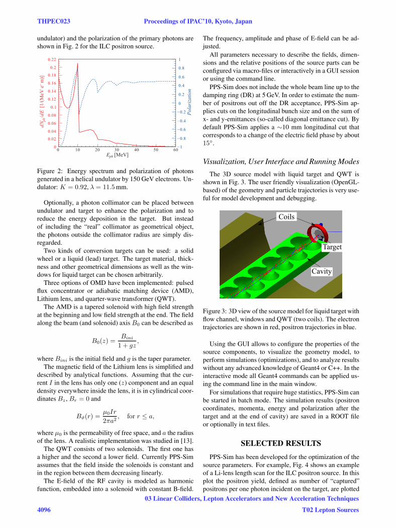
undulator) and the polarization of the primary photons areshown in Fig. 2 for the ILC positron source.
Figure 2: Energy spectrum and polarization of photonsgenerated in a helical undulator by 150 GeV electrons. Un-dulator: K = 0.92, λ = 11.5mm.
Optionally, a photon collimator can be placed betweenundulator and target to enhance the polarization and toreduce the energy deposition in the target. But insteadof including the “real” collimator as geometrical object,the photons outside the collimator radius are simply dis-regarded.
Two kinds of conversion targets can be used: a solidwheel or a liquid (lead) target. The target material, thick-ness and other geometrical dimensions as well as the win-dows for liquid target can be chosen arbitrarily.
Three options of OMD have been implemented: pulsedflux concentrator or adiabatic matching device (AMD),Lithium lens, and quarter-wave transformer (QWT).
The AMD is a tapered solenoid with high field strengthat the beginning and low field strength at the end. The fieldalong the beam (and solenoid) axis B0 can be described as
B0(z) =Bini
1 + gz,
where Bini is the initial field and g is the taper parameter.The magnetic field of the Lithium lens is simplified and
described by analytical functions. Assuming that the cur-rent I in the lens has only one (z) component and an equaldensity everywhere inside the lens, it is in cylindrical coor-dinates Bz , Br = 0 and
Bϑ(r) =μ0Ir
2πa2, for r ≤ a,
where μ0 is the permeability of free space, and a the radiusof the lens. A realistic implementation was studied in [13].
The QWT consists of two solenoids. The first one hasa higher and the second a lower field. Currently PPS-Simassumes that the field inside the solenoids is constant andin the region between them decreasing linearly.
The E-field of the RF cavity is modeled as harmonicfunction, embedded into a solenoid with constant B-field.
The frequency, amplitude and phase of E-field can be ad-justed.
All parameters necessary to describe the fields, dimen-sions and the relative positions of the source parts can beconfigured via macro-files or interactively in a GUI sessionor using the command line.
PPS-Sim does not include the whole beam line up to thedamping ring (DR) at 5 GeV. In order to estimate the num-ber of positrons out off the DR acceptance, PPS-Sim ap-plies cuts on the longitudinal bunch size and on the sum ofx- and y-emittances (so-called diagonal emittance cut). Bydefault PPS-Sim applies a ∼10 mm longitudinal cut thatcorresponds to a change of the electric field phase by about15◦.
Visualization, User Interface and Running Modes
The 3D source model with liquid target and QWT isshown in Fig. 3. The user friendly visualization (OpenGL-based) of the geometry and particle trajectories is very use-ful for model development and debugging.
Coils
Target
Cavity
Figure 3: 3D view of the source model for liquid target withflow channel, windows and QWT (two coils). The electrontrajectories are shown in red, positron trajectories in blue.
Using the GUI allows to configure the properties of thesource components, to visualize the geometry model, toperform simulations (optimizations), and to analyze resultswithout any advanced knowledge of Geant4 or C++. In theinteractive mode all Geant4 commands can be applied us-ing the command line in the main window.
For simulations that require huge statistics, PPS-Sim canbe started in batch mode. The simulation results (positroncoordinates, momenta, energy and polarization after thetarget and at the end of cavity) are saved in a ROOT fileor optionally in text files.
SELECTED RESULTS
PPS-Sim has been developed for the optimization of thesource parameters. For example, Fig. 4 shows an exampleof a Li-lens length scan for the ILC positron source. In thisplot the positron yield, defined as number of “captured”positrons per one photon incident on the target, are plotted
THPEC023 Proceedings of IPAC’10, Kyoto, Japan
4096
03 Linear Colliders, Lepton Accelerators and New Acceleration Techniques
T02 Lepton Sources

together with the positron polarization as function of thelens length.
Llens [mm]2 4 6 8 10 12
25
30
35
40
45
3.5
x
4.0
4.5
5.0
10−3
Yiel
d [e
/ph]
+
Pola
riza
tion
[%]
Figure 4: Positron yield and polarization versus length ofthe Li-lens for an undulator-based source with 150 GeVdrive electron beam, K = 0.92, λ = 11.5mm, Ti-alloytarget of 0.4 radiation length, and a Li-lens with 120 A cur-rent and 8.5 mm radius.
In Fig. 5 the focusing power of the pulsed flux concen-trator is shown. The normalized positron yield (per oneelectron passing 100 m undulator) calculated by PPS-Simfor the ILC source is plotted together with results from ref-erence [14] obtained by combining EGS with Elegant.
ElegantPPS−Sim
Bini [T]0 2 4 6 8 10
Yiel
d[e
/e
]+
_
0
1
2
3
4
5
Figure 5: Normalized positron yield (per one electron pass-ing 100 m undulator) depending on the initial magneticfield of AMD as obtained using EGS and Elegant (dashedline), and using PPS-Sim (solid line). Parameters of thesource: 250 GeV drive beam, K = 0.92, λ = 11.5mm, Titarget of 0.4 X0, taper parameter g = 0.06mm−1, solenoidB = 0.5T.
For the Peak Energy Deposition Density (PEDD) analy-sis a special running mode is provided. A typical exampleof the energy deposition inside the titanium-alloy target isshown in Fig. 6 for the undulator-based source including aphoton collimator.
z [mm]2 4 6 8 10 12 14
r [m
m]
0
1
2
3
4
5
6
7
8
9
10
50
100
150
200
250
300
350
400
450
+/e3MeV/cm
Figure 6: Spatial distribution of energy deposition in thetarget. Source parameters: 150 GeV drive beam, K =0.92, λ = 11.5mm, 4.6 mm collimator aperture, 0.4X0 Titarget.
SUMMARY
PPS-Sim is a flexible Geant4-based tool for positronsource simulation and optimization. It includes a variety ofsource options. The graphical user interface is easy to useand to extend. The visualization of the geometry is use-ful for development and debugging. PPS-Sim is an open-source code and available for download from [1].
REFERENCES
[1] PPS-Sim web site, http://pps-sim.desy.de.
[2] S. Agostinelli et al. (GEANT4 Collaboration), Nucl. Instr.and Meth. A 506, 250 (2003); J. Allison et al., IEEE Trans.Nucl. Sci. 53, 270 (2006).
[3] Electron Gamma Shower (EGS) web site,http://www2.slac.stanford.edu/VVC/egs/.
[4] A. Ferrari, P.R. Sala, A. Fasso, and J. Ranft, “FLUKA:a multi-particle transport code”, CERN 2005-10 (2005),INFN/TC 05/11, SLAC-R-773.
[5] MAD-X web site, http://mad.web.cern.ch/mad/.
[6] Bmad web site, http://www.lns.cornell.edu/∼dcs/bmad.
[7] M. Borland, Advanced Photon Source LS-287, September2000.
[8] K. Flottmann, “ASTRA. A Space Charge Tracking Algo-rithm”, http://wwww.desy.de/∼mpyflo/.
[9] Y.K. Batygin, Nucl. Instrum. Meth. A 539 (2005) 455.
[10] Muons, Inc.: G4beamline,http://g4beamline.muonsinc.com.
[11] bdsim web site,http://www.pp.rhul.ac.uk/twiki/bin/view/JAI/BdSim.
[12] B.M. Kincaid, J. Appl. Phys. 48 (1977) 2684.
[13] A. Mikhailichenko, Cornell University Report (2010) CBN10-3.
[14] W. Gai, (ANL), 2009, private communication.
Proceedings of IPAC’10, Kyoto, Japan THPEC023
03 Linear Colliders, Lepton Accelerators and New Acceleration Techniques
T02 Lepton Sources 4097