Embed Size (px)
Citation preview

PositionServo ETHERNET/IPCommunications Protocol Reference Guide

Copyright ©2008 by Lenze AC Tech Corporation.
All rights reserved. No part of this manual may be reproduced or transmitted in any form without written permission from Lenze AC Tech Corporation. The information and technical data in this manual are subject to change without notice. Lenze AC Tech makes no warranty of any kind with respect to this material, including, but not limited to, the implied warranties of its merchantability and fitness for a given purpose. Lenze AC Tech assumes no responsibility for any errors that may appear in this manual and makes no commitment to update or to keep current the information in this manual.
MotionView®, PositionServo®, and all related indicia are trademarks of Lenze AG in the United States and other countries.
CompoNet™, DeviceNet™, CIP™, CIP Safety™, CIP Sync™, CIP Motion™, DeviceNet Safety™ and EtherNet/IP Safety™ and all related indicia are trademarks of the ODVA (Open DeviceNet Vendors Association). EtherNet/IP™ is a trademark used under license by ODVA.
RSLogix™, RSLogix™ 5000, CompactLogix, CompactLogix 5000, ControlLogix®, MicroLogix™, SoftLogix, Allen Bradley® and all related indicia are trademarks of Rockwell Automation® Corporation.
About These Instructions
This documentation applies to EtherNet/IP communications for the PositionServo drive and should be used in conjunction with the PositionServo User Manual (S94H201) that shipped with the drive. These documents should be read in their entirety as they contain important technical data and describe the installation and operation of the drive.

i P94ETH01D
Contents
1. Safety Information ...................................................................................................11.1 Warnings, Cautions & Notes ............................................................................................. 1
1.2 Reference Documents...................................................................................................... 2
2. Introduction .............................................................................................................32.1 EtherNet/IP Overview ....................................................................................................... 3
2.2 Ethernet TCP/IP Configuration .......................................................................................... 3
3. Installation ..............................................................................................................53.1 Mechanical Installation .................................................................................................... 5
3.2 Electrical Installation ........................................................................................................ 5
3.3 Grounding ........................................................................................................................ 5
3.4 Cabling ............................................................................................................................ 5
3.5 Maximum Network Length ............................................................................................... 5
3.6 Minimum Node to Node Cable Length .............................................................................. 6
3.7 Network Topology ............................................................................................................ 6
3.8 Example Networks ........................................................................................................... 7
4 Configuring EtherNet/IP ...........................................................................................94.1 Connect to the Drive with MotionView OnBoard ................................................................ 9
4.2 Configuring a Scanner or Bridge ..................................................................................... 13
4.3 Adding a Bridge or Scanner to the I/O Configuration ........................................................ 13
4.4 Adding the Adapter and Drive to the I/O Configuration ..................................................... 16
4.5 Saving the Configuration ................................................................................................. 19
5 I/O Messaging ........................................................................................................205.1 Overview of I/O Messaging ............................................................................................. 20
5.2 I/O Assemblies ................................................................................................................ 20
5.3 Using Assemblies for Control and Status/Data Monitoring ............................................... 21
5.4 Using DataLinks .............................................................................................................. 21
5.5 Assembly Object ............................................................................................................. 22
5.6 Example Ladder Logic Program ...................................................................................... 24
6 Explicit Messages ..................................................................................................276.1 Formatting Explicit Messages ......................................................................................... 27
6.2 Performing Explicit Messages ......................................................................................... 29
6.3 Explicit Message Example ............................................................................................... 30

iiP94ETH01D
Contents
7 Ethernet/IP Objects ................................................................................................347.1 Identity Object ................................................................................................................ 34
7.2 PositionServo System Object........................................................................................... 35
7.3 Assembly Object ............................................................................................................. 36
7.4 TCP/IP Interface Object ................................................................................................... 36
7.5 Ethernet Link Object ....................................................................................................... 37
8 Applications ...........................................................................................................388.1 Application Example 1 - Velocity Control ......................................................................... 38
8.2 Application Example 2 - Indexing .................................................................................... 41
8.3 Application Example 3 - Configuration Using Explicit Messages ...................................... 47
8.4 Application Note - Detection of EtherNet/IP Exclusive Ownership Loss ............................ 54

1 P94ETH01D
Safety Information
1. Safety Information1.1 Warnings, Cautions & Notes
Some parts of Lenze controllers (frequency inverters, servo inverters, DC controllers) can be live, with the potential to cause attached motors to move or rotate. Some surfaces can be hot.
Non-authorized removal of the required cover, inappropriate use, and incorrect installation or operation creates the risk of severe injury to personnel or damage to equipment.
All operations concerning transport, installation, and commissioning as well as maintenance must be carried out by qualified, skilled personnel (IEC 364 and CENELEC HD 384 or DIN VDE 0100 and IEC report 664 or DIN VDE0110 and national regulations for the prevention of accidents must be observed).
According to this basic safety information, qualified skilled personnel are persons who are familiar with the installation, assembly, commissioning, and operation of the product and who have the qualifications necessary for their occupation.
Application
Drive controllers are components that are designed for installation in electrical systems or machinery. They are not to be used as appliances. They are intended exclusively for professional and commercial purposes according to EN 61000-3-2. The documentation includes information on compliance with the EN 61000-3-2.
When installing the drive controllers in machines, commissioning (i.e. the starting of operation as directed) is prohibited until it is proven that the machine complies with the regulations of the EC Directive 98/37/EC (Machinery Directive); EN 60204 must be observed.
Commissioning (i.e. starting of operation as directed) is only allowed when there is compliance with the EMC Directive (2004/108/EC).
The drive controllers meet the requirements of the Low Voltage Directive 2006/95/EC. The harmonised standards of the series EN 50178/DIN VDE 0160 apply to the controllers.
The availability of controllers is restricted according to EN 61800-3. These products can cause radio interference in residential areas.
Installation
Ensure proper handling and avoid excessive mechanical stress. Do not bend any components and do not change any insulation distances during transport or handling. Do not touch any electronic components and contacts. Controllers contain electrostatically sensitive components, that can easily be damaged by inappropriate handling. Do not damage or destroy any electrical components since this might endanger your health!
When installing the drive ensure optimal airflow by observing all clearance distances in the drive's user manual. Do not expose the drive to excessive: vibration, temperature, humidity, sunlight, dust, pollutants, corrosive chemicals or other hazardous environments.
Electrical Connection
When working on live drive controllers, applicable national regulations for the prevention of accidents (e.g. VBG 4) must be observed. The electrical installation must be carried out according to the appropriate regulations (e.g. cable cross-sections, fuses, PE connection).

2P94ETH01D
Safety Information
Additional information can be obtained from the national regulation documentation. In the United States, electrical installation is regulated by the National Electric Code (nec) and NFPA 70 along with state and local regulations.
The documentation contains information about installation in compliance with EMC (shielding, grounding, filters and cables). These notes must also be observed for CE-marked controllers. The manufacturer of the system or machine is responsible for compliance with the required limit values demanded by EMC legislation.
Operation
Systems including controllers must be equipped with additional monitoring and protection devices according to the corresponding standards (e.g. technical equipment, regulations for prevention of accidents, etc.). You are allowed to adapt the controller to your application as described in the documentation.
DANGER!
After the controller has been disconnected from the supply voltage, do not touch the live components and power connection, since capacitors could still be charged. Wait at least 60 seconds before servicing the drive Please observe the corresponding notes on the controller.
Do not continuously cycle input power to the controller more than once every three minutes.
Please close all protective covers and doors during operation.
WARNING!
Network control permits automatic operation of the drive. The system design must incorporate adequate protection to prevent personnel from accessing moving equipment while power is applied to the drive system.
Table 1: Pictographs used in these instructions
Pictograph Signal Word Meaning Consequence if Ignored
DANGER! Warning of Hazardous Electrical Voltage.
Reference to an imminent danger that may result in death or serious personal injury if the corresponding measures are not taken.
WARNING! Impending or possible danger to personnel
Death or injury
STOP! Possible damage to equipment Damage to drive system or its surroundings
NOTE Useful tip: If note is observed, it will make using the drive easier
1.2 Reference Documents• EtherNet/IPInformation:http://www.odva.org
• PositionServoProgrammingManual(PM94H201):http://www.lenzeamericas.com
• PositionServoUserManual(S94H201):http://www.lenzeamericas.com
NOTE:
The complete list of variables can be found in the PositionServo Programming Manual (PM94H201).

3 P94ETH01D
Introduction
2. IntroductionEtherNet/IP just like its close siblings DeviceNet and ControlNet, uses CIP (Common Industrial Protocol a.k.a. Control and Information Protocol) to exchange data between devices on an Ethernet network. AC Tech implementation of CIP follows the standard supported by the ODVA (governing organization) and supports the two main types of EtherNet/IP communication: Explicit Messaging and I/O Messaging.
The purpose of this document is to describe the EtherNet/IP implementation specifics for the PositionServo drive as well as provide the necessary information and examples for users and network programmers. This document assumes the reader is familiar with the general concept of CIP and has a basic knowledge of Ethernet TCP/IP communication principles.
2.1 EtherNet/IP OverviewEtherNet/IP implements network protocol using the seven layer Open Systems Interconnection (OSI) model as illustrated in Figure 1. Ethernet has an active infrastructure and as such EtherNet/IP can support an almost unlimited number of point-to-point nodes. The EtherNet/IP system requires just one connection for configuration and control. An EtherNet/IP system uses peer-to-peer communication and can be setup to operate in a master/slave or distributed control configuration.
Layer
Application
Presentation
Session
Transport
Network
Data Link
Physical
IP
TCP UDP
Encapsulation
EthernetCSMA/CD
ControlNetCTDMA
CANCSMA/NBA
DeviceNetPhysical Layer
ControlNetPhysical Layer
EthernetPhysical Layer
DeviceNetTransport
ControlNetTransport
CIP: Connection Management - Message Routing
CIP: Data Management - Explicit Messages, I/O Messages
CIP: Application Layer - Object Library
1
2
4
5
6
7
3
Figure 1: OSI Model
2.2 Ethernet TCP/IP ConfigurationTypically, an EtherNet/IP network is made up of segments containing point-to-point connections in a star configuration as illustrated in Figure 2. At the center of this star topology is a bank of Ethernet 2 & 3 switches that can support a great number of point-to-point nodes.
Network
Message RouterObject
TCP/IP Ethernet
AssemblyObject
TCP/IP InterfaceObject
ParameterObject
Explicit Messages
I/OMessages
Connection ManagerObject
Ethernet InterfaceObject
Application-SpecificObject
IdentityObject
UCMM
Figure 2: EtherNet/IP Star Configuration

4P94ETH01D
Introduction
2.2.1 MultiCast Configuration
By default the PositionServo drive automatically generates the multicast address used for I/O messaging. The default multicast TTL (time to leave) value is 1 which means that the multicast I/O packets will be propagated over the local subnet only.
The user is allowed to explicitly set the drive’s multicast address and TTL values but this feature should be used carefully. In the Communication folder of the MotionView program there is a menu for Ethernet IP settings. The TTL and Mcast Config attributes in the TCP/IP object are also implemented. Note that the Num Mcast value in the Mcast Config attribute must always be 1.
The user configurable PositionServo system variables for multicast are:
Variable ID Meaning
273 TTL
275 Multicast address (default 239.192.15.32)
2.2.2 IGMP Implementation
The IGMP v2 version of the IGMP (Internet Group Management Protocol) is used.
Type Checksum
Group Address
Max Response Time
0 7 8 15 16 31
Message Type0x110x120x160x170x22
General Queryv1 Reportv2 Reportv2 Leavev3 Report
Max Response TimeMaximum time the Querierwaits for report in response
to a membership query
ChecksumThe 1’s complement
of the entire IGMP message
Group AddressIn a general query it is the multicast group address
In other cases it is a specific multicast address
23 24
Figure 3: IGMP v2 Message Format
2.2.3 TCP/IP Sockets
The PositionServo supports up to 3 TCP/IP socket connections.
2.2.4 CIP Connections
The PositionServo supports up to 10 CIP connections.

5 P94ETH01D
Installation
3. InstallationEthernet/IP communication is not supported by the RS232-based PositionServo drive even if the RS232-based drive has the Ethernet option module E94ZAETH1 installed. Ethernet/IP is also not supported by the MVCD PositionServo drives (part number ending in “X”). Ethernet/IP is supported by the MVOB equipped PositionServo drives (part number ending in “M” or “S”).
3.1 Mechanical InstallationNo mechanical installation is necessary. The Ethernet Module is the standard interface on the PositionServo drive.
3.2 Electrical InstallationTable 2 and Figure 4 illustrate the pinout of the PositionServo Ethernet interface. The 8-pin connector provides a standard RJ45 UTP/STP (Unscreened/Screened Twisted Pair) connection to a 10Mbs or 100Mbs Ethernet system.
Table 2: Ethernet Interface Pin DesignationTerminal Name Description
1 TxB (+) Transmit B (+)
2 TxA (-) Transmit A (-)
3 RxB (+) Receive B (+)
4 -- Not Used
5 -- Not Used
6 RxA(-) Receive A (-)
7 -- Not Used
8 -- Not Used
1876
23
45
Figure 4: Ethernet Interface Pin Designation
3.3 GroundingThe PositionServo Ethernet interface is supplied with a grounding tag on the module that should be connected to the closest possible grounding point using the minimum length of cable. This will greatly improve the noise immunity of the module. If standard Ethernet UTP or STP cables are used, supplementary grounding is not required when connecting to the PositionServo Ethernet interface.
3.4 CablingTo ensure long-term reliability it is recommended that any cables used to connect a system together are tested using a suitable Ethernet cable tester, this is of particular importance when cables are made up on site. It is recommended that a minimum specification of CAT5e is installed on new installations, as this gives a good cost performance ratio. If you are using existing cabling this may limit the maximum data rate depending on the cable ratings. In noisy environments the use of STP or fiber optic cable will offer additional noise immunity.
3.5 Maximum Network LengthThe main restriction imposed on Ethernet cabling is the length of a single section of cable as detailed in Table 3. If distances greater than this are required it may be possible to extend the network with additional switches or by using a fiber optic converter. Cabling issues are the single biggest cause of network downtime. Ensure cabling is correctly routed, wiring is correct, connectors are properly fitted and any switches or routers used are rated for industrial use. Office grade Ethernet equipment does not offer the same degree of noise immunity as equipment intended for industrial use.

6P94ETH01D
Installation
Table 3: Maximum Network Length
Type of Cable Data Rate (bits/sec) Maximum Trunk Length (m)
Copper - UTP/STP CAT 5 10M 100
Copper - UTP/STP CAT 5 100M 100
Fiber Optic - Multi-mode 10M 2000
Fiber Optic - Multi-mode 100M 3000
Fiber Optic - Single-mode 10M no standard
Fiber Optic - Single-mode 100M up to 100000
NOTE:
The distances specified are absolute recommended maximums for reliable transmission of data. The distances for the fiber optic sections will be dependent on the equipment used on the network. The use of wireless networking products is not recommended for control systems, as performance may be affected by many external influences.
3.6 Minimum Node to Node Cable LengthThere is no minimum length of cable recommended in the Ethernet standards for UTP or STP. For consistency across fieldbus modules, a minimum network device-to-device distance equal to 1 meter of cable is recommended. This minimum length helps to ensure good bend radii on cables and avoids unnecessary strain on connectors.
3.7 Network TopologyGiven its universal connectivity, an ethernet network may contain varied connection devices including hubs, switches and routers. Mixing commercial and industrial ethernet networks is possible but care should be taken to ensure clean data transmission. A large, high performance industrial Ethernet network is best served by managed switches that permit data control and monitoring capability.
3.7.1 Hubs
A hub provides a basic connection between network devices. Each device is connected to one port on the hub. Any data sent by a device is then sent to all ports (floods) on the hub. The use of hubs is not recommended for use within control systems due to the increased possibility of collisions. Collisions can cause delays in data transmission and are best avoided, in severe cases a single node can prevent other nodes on the same hub (or collision domain) from accessing the network. If using hubs or repeaters you must ensure that the path variability value and propagation equivalent values are checked. This is beyond the scope of this manual.
3.7.2 Switches
Switches offer a better solution to hubs because after initially learning the addresses of connected devices the switch will only send data to the port that has the addressed device connected to it. This prevents excessive traffic. Some managed switches allow the switching of data to be controlled and monitored which may be of particular importance on large or high performance systems. The word “switch” is sometimes used interchangeably with the terms scanner, matrix and bridge.
3.7.3 Routers
A router is used to communicate between two physical networks (or subnets) and provides some degree of security by allowing only defined connections between the two networks. A typical use would be connecting the office and manufacturing networks or connecting a network to an I.S.P (Internet Service Provider). A router is sometimes known as a gateway as it provides a “gateway” between two networks.

7 P94ETH01D
Installation
3.7.4 Firewalls
A firewall allows separate networks to be connected together similar to a router, however the firewall offers more security features and control. Typical features include address translation, port filtering, protocol filtering, URL filtering, port mapping, service attack prevention, monitoring and virus scanning. A firewall is the preferred method of allowing traffic from a manufacturing network to the business network.
3.7.5 VPN (Virtual Private Network)
A VPN is a method of using a non-secure or public network that allows devices to be connected together as if they were connected on a private network. A typical example would be the connection of two remote offices such as London and New York. Each office would require a high speed Internet connection and a Firewall (or VPN device). In order to configure the VPN, encryption keys are exchanged so that both offices can communicate. The data is then sent across the Internet (or shared network) in an encrypted form, giving the illusion of a single connected network (speed limitations may apply).
3.8 Example Networks3.8.1 Single PC to Single PositionServo Drive
Figure 5: PC to PositionServo Drive
3.8.2 Single PC to Multiple PositionServo Drives and Single Switch
PC/Laptop
PositionServo Drives
Switch
Non crossover cableNon crossover cable
(PC to Switch)
(Drives to Switch)
Figure 6: PC to Multiple PositionServo Drives

8P94ETH01D
Installation
3.8.3 Single PC to Multiple PositionServo Drives and Multiple Switches
PC/Laptop
PositionServo Drives
Switch 1
Non crossover cableNon crossover cable
(PC to Switch)
(Drives to Switch)
PositionServo Drives
Switch 2
Non crossover cable
(Drives to Switch)
Non crossover or crossover cable depends on switch(Switch to Switch)
Figure 7: PC to Multiple PositionServo Drives and Multiple Switches

9 P94ETH01D
Commissioning
4 Configuring EtherNet/IPTo setup an Ethernet/IP network, the ethernet port on each device that will be part of the network must be configured. For the example illustrated in sections 4 through 6 of this manual, the devices on the network include an Allen-Bradley 1769-L32E CompactLogix controller, a PC and a PositionServo drive.
4.1 Connect to the Drive with MotionView OnBoardEnsure the drive Run/Enable terminal is disabled then apply the correct voltage to the drive (refer to drive's user manual for voltage supply details).
Refer to the PositionServo User Manual, section 6.2 for full detail on configuring & connecting a drive via MotionView OnBoard (MVOB) software. Contained herein is a brief description of launching MVOB and communicating with the drive.
1. Open your PC’s web browser. Enter the drive’s default IP address [192.168.124.120] in the browser’s Address window.
2. The authentication screen may be displayed if the PC does not have Java RTE version 1.4 or higher. If so, to remedy this situation, download the latest Java RTE from http://www.java.com.
3. When MotionView has finished installing, a Java icon entitled [MotionView OnBoard] will appear on your desktop and the MVOB splash screen is displayed. Click [Run] to enter the MotionView program.
4. Once MotionView has launched, verify motor is safe to operate, click [YES, I have] then select [Connect] from the Main toolbar (top left). The Connection dialog box will appear.
5. Select [Discover] to find the drive(s) on the network available for connection.
[Discover] may fail to find the drive’s IP address on a computer with both a wireless network card and a wired network card. If this happens, try one of the following remedies:
Disable the wireless network card and then use [Discover].Type in the drive’s IP address manually at the box [IP Address].
Then click [Connect]
6. Highlight the drive (or drives) to be connected and click [Connect] in the dialog box.
Figure 8 Connection Box with Discovered Drive
In the lower left of the MotionView display, the Message WIndow will contain the connection status message. The message “Successfully connected to drive B04402200450_192.168.124.120” indicates that the drive B04402200450 with IP address 192.168.124.120 is connected.
10P94ETH01D
Commissioning
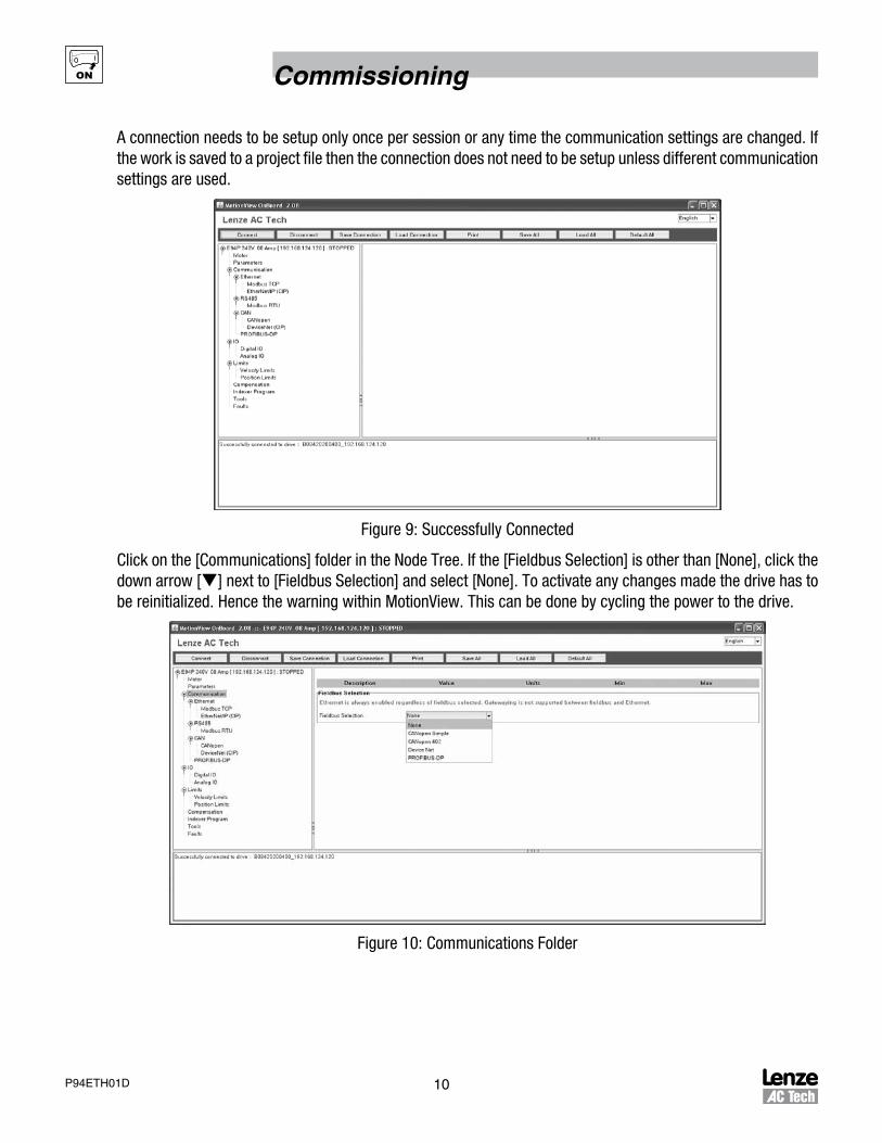
A connection needs to be setup only once per session or any time the communication settings are changed. If the work is saved to a project file then the connection does not need to be setup unless different communication settings are used.
Figure 9: Successfully Connected
Click on the [Communications] folder in the Node Tree. If the [Fieldbus Selection] is other than [None], click the down arrow [q] next to [Fieldbus Selection] and select [None]. To activate any changes made the drive has to be reinitialized. Hence the warning within MotionView. This can be done by cycling the power to the drive.
Figure 10: Communications Folder

11 P94ETH01D
Commissioning
Figure 11: REBOOT Message
Ethernet Hardware Settings
The Ethernet folder displays the IP Address, Subnet Mask and Default Gateway for the drive selected in the Node Tree. The TCP Reply Delay can be set in 1 millisecond increments from 0 to 15ms. To obtain the IP address via DHCP, check the box adjacent to [Obtain IP address using DHCP].
Table 4: Ethernet Hardware Setup
Parameter Range Default Value
Obtain IP Address using DHCP Yes or No No
IP Address ###.###.###.### Automatically Generated 192.168.124.120
Subnet Mask ###.###.###.### 255.255.255.0
Default Gateway ###.###.###.### 192.168.124.1
TCP Reply Delay 0 - 15 milliseconds 2 ms
Figure 12: Ethernet
NOTE:Every time the IP address is reconfigured, the drive must be rebooted so that the change can take effect.

12P94ETH01D
Commissioning
EtherNet/IP Parameters
Defined by the Ethernet hardware settings, the EtherNet/IP folder contains the configuration parameters for the EtherNet/IP (Industrial Protocol). To change an EtherNet/IP parameter, use the pull-down menu to select a pre-defined value or click in the box adjacent to the parameter and enter a numeric value that is within the parameter’s specified range. Table 5 lists the range and default value for each EtherNet/IP parameter. In general, there is no need to change parameters for multicast operations. Consult your IT administrator for these settings as their configuration is very network-specific.
Table 5: EtherNet/IP Parameters
Parameter Range Default Value
Multicast Control Automatically Generated; Explicitly Set Automatically Generated
Multicast TTL 0 - 255 1
Multicast Address ###.###.###.### 239.192.15.32
Input Assembly Links A-D -- --
Enable Enable/Disable Enable
Parameter ID Number Index number of the assigned User Variable V0-V31 In Link A = 100, In Link B = 101,In Link C = 102, In Link D = 103
Units RAM Float (4 Bytes); RAM Integer (4 Bytes) RAM Float (4 Bytes)
Output Assembly Links A-D -- --
Enable Enable/Disable Enable
Parameter ID Number Index number of the assigned User Variable V0-V31 Out Link A = 104, Out Link B = 105,Out Link C = 106, Out Link D = 107
Units RAM Float (4 Bytes); RAM Integer (4 Bytes) RAM Float (4 Bytes)
Figure 13: EtherNet/IP Parameters

13 P94ETH01D
Commissioning
4.2 Configuring a Scanner or BridgeTo configure a simple network like the network illustrated in Figure 14, follow the steps in paragraphs 4.3 through 4.5. This example uses an Allen-Bradley 1769-L32E CompactLogix controller to communicate with PositionServo drives using implicit I/O messaging over an ethernet network. The controller has a scanner (bridge) that needs to be configured. The I/O assembly object instances will be used for status, input and output data and to map them in the controller memory. Section 5.6 illustrates how to write a simple Ladder program to use the I/O messaging for control and status information.
Logic Controller
Network
Laptop
Switch
Figure 14: Example Network
4.3 Adding a Bridge or Scanner to the I/O ConfigurationTo establish communications over an EtherNet/IP network, add the controller and its scanner or bridge to the I/O configuration.
1. Start RSLogix 5000The RSLogix 5000 window opens as illustrated in Figure 15. For the CompactLogix L32E controller, the I/O configuration already includes a local Ethernet port.
If a SoftLogic controller or ControlLogix controller is used then an Ethernet port scanner needs to be added as illustrated in Figure 15.

14P94ETH01D
Commissioning
Figure 15: RSLogix 5000 Window (CompactLogix L32E)
Figure 16: RSLogix 5000 Window (SoftLogix 5800)

15 P94ETH01D
Commissioning
2. For CompactLogix and SoftLogix only:
Right click on [Backplane, 1789-A17/A Virtual Chassis] to choose the Ethernet adapter.
Select [New module] and the “Select Module” dialog box will open.
Under the “By Category” tab, click the [+] icon to expand the [Communications] folder
Select the EtherNet/IP scanner or bridge used by your controller. (This example uses the SoftLogix5800 EtherNet/IP)
Then select the major revision of your controller’s firmware in the Major Revision box.
Figure 17: Ethernet Adapter selection (SoftLogix 5800)
3. Click [OK].
The Module Properties dialog box opens. For the CompactLogix controller, right click on [1769-L32E EthernetPort LocalENB] in I/O folder and then select “Properties”.
Figure 18: Ethernet Scanner Properties Setup (SoftLogix 5800)

16P94ETH01D
Commissioning
4. Set the “New Module” properties using the information in Table 6
Table 6: “New Module” Fields
Box Type
Name A name to identify the scanner or bridge.
Slot The slot # of the EtherNet/IP scanner or bridge in the rack.
Revision The minor revision of the firmware in the scanner. (You have already set the major revision in the Select Module Type dialog box)
IP Address The IP address of the EtherNet/IP scanner or bridge.
Electronic Keying Compatible Module. This setting for Electronic Keying ensures the physical module is consistent with the software configuration before the controller and scanner or bridge make a connection. Therefore, ensure that you have set the correct revision in this dialog box. Refer to the online Help if the controller and scanner have problems making a connection and you want to change this setting.
5. Click [OK] to finish.
The scanner (or bridge) is now configured for the EtherNet/IP network. Its name is now listed in the I/O Configuration folder.
4.4 Adding the Adapter and Drive to the I/O ConfigurationTo transmit data between the scanner (or bridge) and the adapter, the PositionServo drive must be added as a slave device of the scanner.
1. In the Control Organizer pane, right-click on the scanner or bridge and select [New Module]. For this example, right-click on the [1769-L32E Ethernet Port LocalENB for CompactLogix]. If using the SoftLogix controller right-click on [1789-L60 SoftLogix_With_SimpleServo].
2. The “Select Module” dialog box will open as illustrated in Figure 19.
Figure 19: Select Module Dialog Box

17 P94ETH01D
Commissioning
3. Select [ETHERNET-MODULE] to configure, and then click [OK]. The Module Properties dialog box will open as shown in Figure 20.
Figure 20: Module Properties Dialog Box
4. In the General tab, edit the adapter information as specified in Table 7.
Table 7: Adapter Properties
Box Type
Name A name to identify the adapter and drive.
Comm. Format Data – REAL – With Status
This will treat data as real (float) numbers and send status information that is packed as 32 bit words
IP Address The IP address of the drive controller you intend to connect to
5. Click on the [Connection] tab and edit the connection parameters as specified in Table 8.
Table 8: Connection Parameters
Box Assembly Instance Size
Input 105 (This value is required) 9 (This value is the exact size of the assembly)
Output 106
108
2 (If using 106)
up to 6 (This value is the exact size of the assembly)
Configuration 103 (This value is required) 0
Status Input 104 (This value is required) 2 (This value is required)
Status Output 109 (This value is required)

18P94ETH01D
Commissioning
6. Click [Next >] to display the next page.
7. In the Requested Packet Interval (RPI) box, set the value to 5.0 milliseconds or greater. This value determines the maximum interval that a controller should use to move data to or from the adapter. To conserve bandwidth, use higher values for communicating with low priority devices.
8. Click [Finish].
The new node (“SimpleServo” in this example) now appears under the scanner or bridge (“1769-L32E…” in this example) in the I/O Configuration folder as shown in Figure 21. To view the module-defined data types and tags that have been automatically created, double-click on the [Data Types] folder and then double-click on the [Module-Defined] folder. After the configuration is saved and downloaded, these tags allow the user to access the Input and Output data of the adapter via the controller’s ladder logic.
Figure 21: Module-Defined Tags

19 P94ETH01D
Commissioning
4.5 Saving the ConfigurationAfter adding the scanner (or bridge) and the adapter to the I/O configuration, the configuration must be downloaded to the controller. The configuration should also be saved to a file on your computer.
1. On the top toolbar, click [Communications] then select [Download] from the pull down menu. The Download dialog box will open.
NOTE:
If a message box reports that RSLogix is unable to go online, then select ‘Communications Who Active’ to try and find your controller in the ‘Who Active’ dialog box. If the controller is not shown, then the Ethernet/IP driver needs to be added or configured in RSLinx. Refer to the RSLinx online help.
2. Click [Download] to download the configuration to the controller. When the download is successfully completed, RSLogix enters online mode and the I/O OK box in the upper-left part of the screen is green.
3. On the top toolbar, click [File] then select [Save] from the pull down menu. If this is the first time the project is saved, then the [Save As] dialog box will open. Navigate to a folder, type a file name and then click [Save] to save the configuration to a file on your computer.

20P94ETH01D
Cyclic Data Access
5 I/O Messaging5.1 Overview of I/O Messaging
Typically I/O messaging is used for the data exchange between a scanner and an adapter device in a cyclic manner. Therefore it is used for data that needs to be updated periodically. A good example is the reference set point value for velocity or torque. Imagine a PLC that calculates the needed speed based on a specific condition of the system (conveyor for example) and periodically sends the new demanded speed over the interface to the drive.
Other examples include fetching data from the drive for monitoring purposes or perhaps controlling functions like current velocity, current and acceleration. In this case data flows from the drive to the PLC. Since these quantities are variables that change over time, they need to be updated (received) periodically.
Table 9: PositionServo implementation of Slave I/O Messaging
Feature Implement Slave Message?
Bit strobe N
Cyclic Y
Change of State N
Polling (released as Application trigger) Y
Input only connection Y
Exclusive owner Y
Listen only connection Y
5.2 I/O Assemblies5.2.1 General Information
PositionServo Ethernet/IP implementation supports the I/O assembly object class 0x04. PositionServo assemblies are static. There are several Input and Output pre-defined assemblies (assembly object instances) that can be used for data exchange. The terms Input and Output refer to the point of view of the scanner. Output data is produced by the scanner and consumed by the adapter. Input data is produced by the adapter and consumed by the scanner. The PositionServo is always an adapter device. An example of a scanner is a PLC or CLC (Continuous Loop Controller).
Depending on the assembly number the memory map of the data can have a different size and meaning. Please refer to the detailed assembly contents later in this chapter.
5.2.2 Important Note for Input Assemblies
Input assemblies (adapter to scanner) are mapped to the adapter memory from byte 0. There is no preceding 4 byte header like that found in most Allen-Bradley equipment. The PositionServo does not use preceding header functionality for real time status. So the start address in the assembly memory map is the actual start of the 1st assembly data item. The user should supply the actual assembly length when mapping the input assembly to the controller memory.
5.2.3 Important Note for Output Assemblies
Output assemblies (scanner to adapter) are assumed to have the preceding 4 byte header. When mapping the assembly this header will automatically be added to the data stream by most AB PLC/CLC equipment. If you use equipment other than AB for the scanner, configure it to send the 4 byte header preceding the actual assembly data. The data in the header should be set to 0.

21 P94ETH01D
Cyclic Data Access
5.3 Using Assemblies for Control and Status/Data MonitoringOutput assemblies are commonly used for controlling the enable/disable state of the drive and for supplying the velocity or torque reference.
Input assemblies are commonly used to monitor the drive status and run-time quantities such as current velocity, current, actual position and position error.
The recommended configurations for I/O assemblies are:
Output assembly - instance #106
Input assembly - instance #104 and #105 (used for status read)
5.4 Using DataLinksA DataLink is a mechanism used by the PositionServo drive to transfer data to and from the PLC controller.
DataLinks are the data pointers used in some of the input and output assemblies. There are 4 input DataLinks and 4 output DataLinks. DataLinks are configured through their corresponding control variable. The lower word (LSW) of the control variable contains any valid system variable ID. The high word (MSW) contains the control and information bits (as shown in Table 12). When the DataLink is used in an assembly, the value of the parameter with the ID whose ID is in DataLink’s LSW will be transferred by the assembly. Since any PositionServo variable can be accessed as a Real or 32-bit integer, there is a control bit in the Datalink’s control word to configure the presentation format of the variable’s value.
Datalink’s control word is a regular system variable and can be accessed by an explicit message or from the user’s program. Tables 10 and 11 provide the variable ID’s for the input and output datalinks.
Table 10: Input DataLinks (for IN assembly)
Link Variable ID
LinkA_in 261
LinkB_in 262
LinkC_in 263
LinkD_in 264
Table 11: Output DataLinks (for OUT assembly)
Link Variable ID
LinkA_out 265
LinkB_out 266
LinkC_out 267
LinkD_out 268
Table 12: DataLink’s Control Word
MSW (bits 16-31) LSW (bits 0-15)
Bit 31 Bit 30 Bits 29-16 Bits 15-0
Enable Format Reserved (Set to 0) ID

22P94ETH01D
Cyclic Data Access
Enable: Enable the transfer data
Format: Data presentation format 0 = U32 (32 bit integer) 1 = F32 (Real)
ID: variable ID, link uses data from/for
Example:
A DataLink needs to be configured to the transfer data of the Phase Current in REAL format. The ID of VAR_PHCUR (Phase current) is 188 (dec). The VAR ID List is published in the PositionServo Programming Manual (PM94H201). As shown in Table 13, the control word structure for this example DataLink is C00000BC (hex) or 322125660 (decimal).
Table 13: Example Control Word Structure
MSW (bits 31-16) LSW (bits 15-0)
Bit 31 Bit 30 Bits 29-16 Bits 15-0
1 1 0 ... 0 BC (h), 188 (d)
5.5 Assembly ObjectAn Assembly Object is the “assembly” or mapping of data from different instances of various classes into a single attribute. With assembly mapping, the I/O data is produced in one block. An assembly object can be used to configure a device using one block of data instead of setting the individual device parameters.
In a device (PositionServo drive) an input assembly collects data from the device and puts it on the network for the master (controlling) device to consume. An output assembly consumes data sent out by the controlling device from the network and writes that data to the output application (driving a motor).
Table 14: Assembly Object Instances:
Assembly Object Instances
Assembly # Name
103 Dummy Assembly required for implicit configuration. Contains no data.
IN 104 PositionServo Status and IO Assembly
IN 105 PositionServo universal monitor
OUT 106 PositionServo basic control
OUT 108 PositionServo extended control
OUT 109 PositionServo “keep alive”
Table 15: Assembly #104 PositionServo Status and I/O Assembly
32-bit WORD Variable ID Type Name
0 -- U32 STATUS2 WORD (refer to Table 18)
1 65 U32 INPUTS
Table 16: Assembly #109 PositionServo “keep alive”
32-bit WORD Variable ID Type Name
0 272 U32 CIP heartbeat
Assembly #109 is used for indication of the communication activity. It can also be used with AB PLC controllers as Status Assembly when setup as the data scanner.

23 P94ETH01D
Cyclic Data Access
NOTE:
The Variable ID is the PositionServo variable’s index number. Refer to the PositionServo Programming Manual (PM94H201)
STATUS2 WORD format
The STATUS2 WORD includes bits from the PositionServo STATUS (#53) and EXSTATUS (#54) system variables as shown in Table 17.
Table 17: STATUS2 Word
Byte Bit7 Bit6 Bit5 Bit4 Bit3 Bit2 Bit1 Bit0
0 Motion Suspended
Registration Captured
I Limit Motion Q Empty
Motion QFull
In Position Fault Enable
1 Homed Homing Active Negative LS Engaged
Positive LS Engaged
Interface Control Disabled
Motion Completed
Reserved
2 0
3 0
Table 18: Mapping STATUS2 bits to STATUS (PID 54) and EXSTATUS (PID 83)
STATUS2 bits Function STATUS / EXSTATUS bits
0 Drive Enabled STATUS.0
1 Drive Fault STATUS.3
2 Motion completed and position within specified limits STATUS.5
3 Motion stack full STATUS.7
4 Motion stack empty STATUS.8
5 Current limit reached STATUS.13
6 Registration position obtained STATUS.19
7 Motion suspended STATUS.22
8 Reserved STATUS.24
9 Motion completed (velocity =0 and stack empty) STATUS.25
10 Interface control is disabled STATUS.27
11 Positive limit switch engaged STATUS.28
12 Negative limit switch engaged STATUS.29
13 Homing in progress EXSTATUS.21
14 Homed EXSTATUS.22
Table 19: Assembly #105: PositionServo Universal Monitor
32-bit Word Variable ID Type Name
0 260 F32 Actual Velocity
1 215 F32 Actual Position
2 216 F32 Position error
3 188 F32 Phase current
4 213 F32 Registered position
5 mapped F32 DataLink_A_in
6 mapped F32 DataLink_B_in
7 mapped F32 DataLink_C_in
8 mapped F32 DataLink_D_in
NOTE:
See section 5.4, Using DataLinks, for details on DataLinks A-D

24P94ETH01D
Cyclic Data Access
Table 20: Assembly #106 PositionServo Basic Control
32-bit Word Variable ID Type Name
0 52 F32 DRIVE ENABLE: Non 0 = enabled, 0 = disabled
1 139 F32 REFERENCE: Velocity mode = velocity in RPS;Current mode = current in phase A(rms)
Table 21: Assembly #108: PositionServo Extended Control.
32-bit Word Variable ID Type Name
0 52 F32 DRIVE ENABLE: Non 0 = enabled, 0 = disabled
1 139 F32 REFERENCE: Velocity mode = velocity in RPS;Current mode = current in phase A(rms)
2 mapped F32 DataLink_A_out
3 mapped F32 DataLink_B_out
4 mapped F32 DataLink_C_out
5 mapped F32 DataLink_D_out
NOTE:
The Variable ID is the PositionServo variable’s index number. Refer to the PositionServo Programming Manual (PM94H201)
NOTE:
Refer to section 5.4, Using DataLinks, for details on DataLinks A-D
5.6 Example Ladder Logic ProgramThe example Ladder Logic program illustrated in this section works with the CompactLogix controller and PositionServo drives.
5.6.1 Function of Example Program
This example program allows the user to:
1. Obtain status information from the drive.2. Use the Logic Command to control the drive (for example enable/disable).3. Send a Reference to the drive and receive Feedback from the drive.
5.6.2 RSLogix 5000 Configuration
Controller Tags
When the adapter and drive are added to the I/O configuration (Section 4.4 Fig. 21), the RSLogix 5000 controller automatically creates the controller tags for these devices. This example program uses the controller tags shown in Figure 22.
+ - SimpleServo:I {. . .} {. . .} AB:ETHERNET_MODULE_REAL_36Bytes:I:0
+ - SimpleServo:O {. . .} {. . .} AB:ETHERNET_MODULE_REAL_8Bytes:O:0
+ - SimpleServo:S {. . .} {. . .} AB:ETHERNET_MODULE_DINT_8Bytes:S:0
Figure 22: Controller Tags

25 P94ETH01D
Cyclic Data Access
Click on the [+] icon next to the tag name to expand the tags and reveal the output and input configuration. The output tag for this example program requires two REAL data words as shown in Figure 22. The input tag for this example requires nine REAL data words (Figure 23) and input status tag requires two 32-bit words
- SimpleServo:I {. . .} {. . .} AB:ETHERNET_MODULE_REAL_36Bytes:I:0
- SimpleServo:I.Data {. . .} {. . .} Float REAL[9]
SimpleServo:I.Data[0] 0.0 Float REAL
SimpleServo:I.Data[1] 0.0 Float REAL
SimpleServo:I.Data[2] 0.0 Float REAL
SimpleServo:I.Data[3] 0.0 Float REAL
SimpleServo:I.Data[4] 0.0 Float REAL
SimpleServo:I.Data[5] 0.0 Float REAL
SimpleServo:I.Data[6] 0.0 Float REAL
SimpleServo:I.Data[7] 0.0 Float REAL
SimpleServo:I.Data[8] 0.0 Float REAL
- SimpleServo:O {. . .} {. . .} AB:ETHERNET_MODULE_REAL_8Bytes:O:0
- SimpleServo:O.Data {. . .} {. . .} Float REAL[2]
SimpleServo:O.Data[0] 0.0 Float REAL
SimpleServo:O.Data[1] 0.0 Float REAL
- SimpleServo:S {. . .} {. . .} AB:ETHERNET_MODULE_DINT_8Bytes:S:0
u - SimpleServo:S.Data] {. . .} {. . .} Decimal DINT[2]
+ SimpleServo:S.Data[0] 0 Decimal DINT
+ SimpleServo:S.Data[1] 0 Decimal DINT
Figure 23: Input, Output and Status Tags for Ladder Logic Program
Program Tags
In addition to the controller tags that are automatically created, the following program tags must be created for this example program.
Name Value Force Mask Style Data Type Description
CMD_DriveEnable Decimal BOOL Enable command
+ Simple Servo:C {. . .} {. . .} AB:ETHERNET_MODULE:C:0
+ SimpleServo:I {. . .} {. . .} AB:ETHERNET_MODULE_REAL_36Bytes:I:0
+ SimpleServo:O {. . .} {. . .} AB:ETHERNET_MODULE_REAL_8Bytes:O:0
+ SimpleServo:S {. . .} {. . .} AB:ETHERNET_MODULE_DINT_8Bytes:S:0
VelocityReferenceRPS 0.0 Float REAL Drive velocity reference
StatusFlag_DriveEnabled 0 Decimal BOOL
StatusFlag_DriveFaut 0 Decimal BOOL
ActualVelocity 0.0 Float REAL Feedback velocity from the...
CMD_ReferenceVelocity 0.0 Float REAL Velocity set point reference
DriveEnable 0.0 Float REAL Drive enable control variable...
u PLCOUT_DriveEnabled 0 Decimal BOOL
PLCOUT_DriveFault 0 Decimal BOOL
Figure 24: Program Tags for Example Program
ffr
26P94ETH01D
Cyclic Data Access
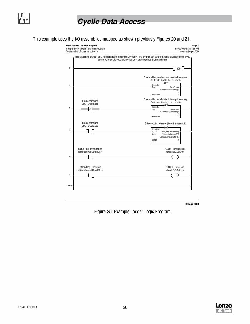
This example uses the I/O assemblies mapped as shown previously Figures 20 and 21.
NOP0
1
2
3
4
5
(End)
This is a simple example of IO messaging with the SimpleServo drive. The program can control the Enable/Disable of the drive,set the velocity reference and monitor drive status such as Enable and Fault
Main Routine - Ladder DiagramCompactLogix1: Main Task: Main ProgramTotal number of rungs in routine: 6
Page 1mm/dd/yyyy hh:mm:ss PM
CompactLogix1.ACD
Enable commandCMD_DriveEnable
Enable commandCMD_DriveEnable
Status Flag DriveEnabled<SimpleServo: S.Data[0].0>
Status Flag DriveFaut<SimpleServo: S.Data[0].1>
PLCOUT DriveFault<Local: 3:O.Data.1>
PLCOUT DriveEnabled<Local: 3:O.Data.0>
Drive velocity reference (Word 1 in assembly)
Drive enable control variable in output assembly.Set to 0 to disable, to 1 to enable
Drive enable control variable in output assembly.Set to 0 to disable, to 1 to enable
CPTComputeDest DriveEnable
<SimpleServo:O.Data[0]>0.0
1Expression
CPTComputeDest DriveEnable
<SimpleServo:O.Data[0]>0.0
0Expression
COTCopy FileSource CMD_ReferenceVelocity
<SimpleServo:O.Data[1]>
1Length
Dest VelocityReferenceRPS
RSLogix 5000
Figure 25: Example Ladder Logic Program

27 P94ETH01D
Acyclic Data Access
6 Explicit MessagesExplicit Messaging is used to transfer data that does not require continuous updates. With Explicit Messaging, you can configure and monitor a slave device’s parameters on the EtherNet/IP network. This section provides information and examples that explain how to use Explicit Messaging to monitor and configure a PositionServo drive.
STOP!
Risk of injury to personnel and/or damage to equipment exists. The examples in this publication are intended solely for purposes of example. Lenze AC Tech Corporation does not assume responsibility or liability (to include intellectual property liability) for actual use of the examples shown in this publication.
STOP!
Risk of equipment damage exists. If Explicit Messages are programmed to frequently write parameter data to Non-Volatile Storage (NVS), the NVS will quickly exceed its life cycle and cause the drive to malfunction. Do not create a program that frequently uses Explicit Messages to write parameter data to NVS. DataLinks do not write to NVS and should be used for frequently changed parameters.
6.1 Formatting Explicit MessagesExplicit Messages for the ControlLogix Controller:
CompactLogix accommodates both downloading Explicit Message Requests and uploading Explicit Message Responses. The controller can accommodate one request or response for each transaction block. Each transaction block must be formatted as shown in the Figure 26.
Figure 26: Explicit Message Configuration Dialog Box

28P94ETH01D
Acyclic Data Access
NOTE:To display the Message Configuration dialog box in RSLogix 5000, add a message instruction (MSG), create a new tag for the message (properties: Base tag type, MESSAGE data type, controller scope), and click the Configure button.
Table 22: Configuration Dialog Fields for Explicit Message in RSLogix 5000
Box Description
Message Type The message type is usually CIP Generic.
Service Type The service type indicates the service (for example, Get Attribute Single or Set Attribute Single) to be performed. Available services depend on the class and instance in use.
Service Code The service code is the code for the requested EtherNet/IP service. This value changes based on the Service Type that has been selected. In most cases, this is a read-only box. If you select “Custom” in the Service Type box, then you need to specify a service code in this box (for example, E(h) for a Get Attributes Single service or 10(h) for a Set Attributes Single service)
Class The class is an EtherNet/IP class. Refer to Section 7, EtherNet/IP Objects, for available classes. The most frequently used classes for the PositionServo are: 4 (Assembly object) and 64(h) PositionServo System variables class.
Instance The instance is an instance (or object) of an EtherNet/IP class. Refer to Section 7, EtherNet/IP Objects, for available instances for each class.
Attribute The attribute is a class or instance attribute. Refer to Section 7, EtherNet/IP Objects, for available attributes for each class or instance.
Source Element This box contains the name of the tag for any service data to be sent from the PLC to the drive.
Source Length This box contains the number of bytes of service data to be sent in the message.
Destination This box contains the name of the tag that will receive service response data from the adapter and drive.
Path The path is the route that the message will follow. Tip: Click Browse to find the path or type in the name of an adapter that you previously mapped.
Name The name for the message.

29 P94ETH01D
Acyclic Data Access
6.2 Performing Explicit MessagesThere are five basic events in the Explicit Messaging process as defined herein and illustrated in Figure 27. The details of each step will vary depending on the controller (ControlLogix, PLC, or SLC). Refer to the documentation for your controller.
NOTE:
There must be a request message and a response message for all Explicit Messages, whether you are reading or writing data.
Logic Controller
PositionServo Drive
1
2 3
4
5 CompleteExplicit Message
RetrieveExplicit MessageResponse
Setup and SendExplicit MessageRequest
Figure 27: Explicit Messaging Process
Event in Explicit Messaging Process:
1. Format the required data and setup the ladder logic program to send an Explicit Message request to the scanner or bridge module (This is a download).
2. The scanner (or bridge) module transmits the Explicit Message Request to the slave device over the EtherNet/IP network.
3. The slave device transmits the Explicit Message Response back to the scanner. The data is stored in the scanner buffer.
4. The controller retrieves the Explicit Message Response from the scanner’s buffer (This is an upload).
5. The Explicit Message is complete.
The scanner module may be integrated with the controller as it is in the CompactLogix controller.

30P94ETH01D
Acyclic Data Access
6.3 Explicit Message ExampleTo format and execute a [Get Attribute Single] or [Set Attribute Single] Explicit Message using a CompactLogix controller, use this example program.
Message Formats
When formatting an example message, refer to Formatting Explicit Messages in this chapter for an explanation of the content of each box. Also, to format and execute these example messages use the Controller tags displayed in Figure 28.
Scope CompactLogix1 Show... STRING, ALARM, AXIS_CONSUMED, AXIS_GENERIC, AXIS_GENERIC_DRIVE, AXIS_SERVO, AXIS_SEF
Name Alias For Base Tag Data Type Style Description
u + Simple Servo:C AB:ETHERNET_MOD...
+ SimpleServo:S AB:ETHERNET_MOD...
+ SimpleServo:I AB:ETHERNET_MOD...
+ SimpleServo:O AB:ETHERNET_MOD...
CMD_GetValue BOOL Decimal
CMD_SetValue BOOL Decimal
+ GetAttribute_Message MESSAGE
+ SetAttribute_Message MESSAGE
Value_Get REAL Float Value received from...
Value_Set REAL Float Value to send to drive.
Figure 28: Controller Tags for Explicit Message Example
Ladder Logic Rungs
The ladder logic rungs for the examples in this chapter can be appended after rung 5 in the ladder logic program illustrated in Figure 25 or the program can be constructed as a stand alone program.
q

31 P94ETH01D
Acyclic Data Access
6.3.1 Example of Get Attribute Single Message (Rung 1 of Figure 31)
Figure 29 illustrates the configuration of the message to read the value from the drive to the PLC controller memory. In this example, the PLC reads instance #100 (User Variable V0) from the PositionServo system variables class 64(h) and stores it in the controller tag Value_Get.
In the [Message Configuration] menu set the parameters for this example as listed in Table 23 and illustrated in Figure 29.
Table 23: Message Configuration Parameters for Get Attribute SingleStep 1 Step 2 Step 3
Click on the [Tag] tab and set: Click on the [Communication] tab and set: Click on the [Configuration] tab and set:
Tag Name: GetAttribute_Message Path: SimpleServo Message Type: CIP Generic
Description: leave blank Communication Method: CIP Service Type: Get Attribute Single
Type: Base Connected: Put a check in this box Service Code: e
Alias For: leave blank Instance: 100
Data Type: MESSAGE Class: 64
Scope: CompactLogix1 Attribute: 2
Style: leave blank Source Element: leave blank
Source Length: 0
Destination: Value_Get
Figure 29: Get Attribute Single

32P94ETH01D
Acyclic Data Access
6.3.2 Example of Set Attribute Single Message (Rung 2 of Figure 31)
Figure 30 illustrates the configuration of the message to write the value from the PLC controller memory to the drive. In this example, the PLC writes instance #100 (User Variable V0) from the controller tag Value_Set.
Table 24: Message Configuration Parameters for Set Attribute Single
Step 1 Step 2 Step 3
Click on the [Tag] tab and set: Click on the [Communication] tab and set: Click on the [Configuration] tab and set:
Tag Name: SetAttribute_Message Path: SimpleServo Message Type: CIP Generic
Description: leave blank Communication Method: CIP Service Type: Set Attribute Single
Type: Base Connected: Put a check in this box Service Code: 10
Alias For: leave blank Instance: 100
Data Type: MESSAGE Class: 64
Scope: CompactLogix1 Attribute: 2
Style: leave blank Source Element: Value_Set
Source Length: 4
Destination: leave blank
Figure 30: SetAttribute_Single

33 P94ETH01D
Acyclic Data Access
NOP0
1
2
(End)
EN
DN
This is a simple example that allows the user to send and receive data by executing Explicit Messages.It uses the Get Attribute Single and Set Attribute Single methods to read/write data.
Main Routine - Ladder DiagramCompactLogix1: Main Task: Main ProgramTotal number of rungs in routine: 3
Page 1mm/dd/yyyy hh:mm:ss PM
CompactLogixExplicitMessaging.ACD
CMD_GetValue
CMD_SetValue
MSGType - CIP Generic
Message Control GetAttribute_Message
MSG
RSLogix 5000
ER
. . .
Type - CIP Generic
Message Control SetAttribute_Message . . .EN
DN
ER
Figure 31: Example Ladder Logic Explicit Message Program

34P94ETH01D
Acyclic Data Access
7 Ethernet/IP ObjectsSection 7 contains information about the Ethernet/IP objects that can be accessed using Explicit Messages. For information on the format of Explicit Messages and example ladder logic programs, refer to section 6.
Table 25: Ethernet/IP Objects
Object Class Code
Hex Dec
Identity 0x01 1
Assembly 0x04 4
System940 0x64 100
TCP/IP Interface Object 0xF5 245
Ethernet Link Object 0xF6 246
The CIP family of protocols has a library of commonly defined objects currently divided into 46 object classes. Class 1 = DeviceNet, Class 2 = EtherNet/IP and Class 3 = ControlNet. Refer to the EtherNet/IP specification for more information about Ethernet/IP objects. Information about the EtherNet/IP specification is available on the ODVA web site (http://www.odva.org).
7.1 Identity ObjectThe Identity Object defines the device. A device typically does not change its identity so all attributes are normally read only. The identity object’s data can be queried from a target node without knowing what that device is before a message is sent. From this data, the EDS file of the device can be identified.
Class Code 0x01
Class Attributes:
Revision 1
Max Instance 1
Number Instance
Max ID# class attribute
Max ID# instance attribute
Class Services:
Get_Attribute_Single()
Instance 1
Instance Attributes
Vendor ID
Device Type
Product Code
Revision
Major
Minor
Product Name EnetIP 940
Instance Services
Get_Attribute_All
Get_Attribute_Single
Reset

35 P94ETH01D
Acyclic Data Access
7.2 PositionServo System ObjectThe PositionServo system object encapsulates all valid PositionServo variables. Each PositionServo variable is represented by an instance of a System940 object. The instance number therefore matches the variable’s index. A complete list of PositionServo variables with their corresponding indices is in the PositionServo Programming Manual (PM94H201).
All aspects of control and parameterization in the PositionServo drive are accomplished through the system variables. Some of the variables are parameters such as Current Limit or Target Position. Some of the variables are action properties, i.e. writing values to these variables will execute a particular process. As an example, writing to variable VAR_ENABLE (ID=52), a non-0 value will enable the drive. Writing the same variable with a 0 value will disable the drive. Another example could be writing the variable VAR_MOVED with a value of 10, which would execute relative motion for 10 user units.
Every variable in the PositionServo can be read/written as a 32-bit INTEGER or 32-bit REAL(float) value. Conversion is done automatically. In addition each variable can be read from its RAM (current) copy or from non-volatile (EPM) storage. The value is initialized at the time of power up.
To accomodate different access (RAM or EPM) and format (integer or float) types, attributes are implemented. For example to reach variable VAR_CURRENTLIMIT (ID=30) as FLOAT in RAM (run-time value) you would use InstanceID = 30 with attrubute 2. For the same variable accessed in EPM (non-volatile copy) you would use attribute 3.
Class Code 0x64
Class Attributes:
Class Services:
Instance Attributes
Integer, RAM 0
Integer, EPM 1
Float, RAM 2
Float, EPM 3
String, RAM 4
String, EPM 5
Instance Services
Get_Attribute_All
Get_Attribute_Single
Instance Instance = variable ID.
Refer to PositionServo Programming Manual (PM94H201) for variable ID list.
For example: Instance of VAR_CURRENTLIMIT is 30 since its ID=30
NOTE:For Attributes 4 and 5, the PositionServo uses a 4 byte header in the data to denote the number of bytes in the ASCII string AFTER the 4 byte header. When performing an explicit write to either Attributes 4 or 5 the user must set the length of the message equal to the number of ASCII bytes for the data +4.
NOTE:Attributes 1, 3 and 5 are WRITE ONLY to the EPM. Attempts to read attributes 1, 3 or 5 result in the data pulled from attributes 0, 2 and 4 respectively.

36P94ETH01D
Acyclic Data Access
7.3 Assembly ObjectAn Assembly Object is the “assembly” or mapping of data from different instances of various classes into a single attribute. With assembly mapping, the I/O data is produced in one block. An assembly object can be used to configure a device using one block of data instead of setting the individual device parameters.
Class Code 0x04
Class Attributes:
Revision 2
Max Instance
Class Services:
Get_Attribute_Single()
Instances:
Refer to Table 14
Instance Attributes
3
Instance Services
Get_Attribute_All
Get_Attribute_Single
7.4 TCP/IP Interface ObjectThe TCP/IP Interface object is the connection object that allows for I/O and Explicit messages to be sent from the device on the network to the other devices.
Class Code 0xF5
Class Attributes:
Revision 1
Max Instance
Number Instance
Class Services:
Get_Attribute_All
Get_Attribute_Single
Instance Attributes
Status
Configuration Capability 6
Configuration Control
Physical Link -> Path 0x20 0xF6 0x24 0x01
Interface Configuration
Host Name
TTL
Mcast Config
Instance Services
Get_Attribute_Single
Set_Attribute_Single

37 P94ETH01D
Acyclic Data Access
7.5 Ethernet Link ObjectThe Ethernet Link object is the network link object that defines the CIP as Ethernet, DeviceNet or ControlNet.
Class Code 0xF6
Class Attributes:
Revision 1
Max Instance 1
Number Instance
Class Services:
Get_Attribute_All()
Get_Attribute_Single()
Instance Attributes
Interface Speed 10
Interface Flags
Physical Address
Instance Services
Get_Attribute_Single
Get_Attribute_All
Set_Attribute_Single
Instance Specific Service
Get_and_Clear()
Instance
none

38P94ETH01D
Applications
8 Applications8.1 Application Example 1 - Velocity Control
This application illustrates how to control velocity using an Allen-Bradley PLC and an AC Tech PositionServo drive.
Objective:
This example shows how to use I/O messaging (I/O scan) to control the PositionServo drive in velocity mode using Ethernet/IP communication protocol.
Equipment:
1. PositionServo drive (firmware revision 3.4 or later)
2. Allen-Bradley PLC SoftLogix (CompactLogix, ControlLogix can be used with modifications to the I/O mapping specific to these models)
3. Ethernet hub or switch.
Description:
This example implements 4 simple presets of velocity drive with the velocity window comparator driven by the actual velocity read from the drive over the Ethernet/IP interface.
PositionServo drives support I/O messaging. I/O messaging is convenient when data must be updated cyclically i.e. within a certain update time interval (rate) like a speed or torque reference. The PositionServo drive has an Assembly Object (class 0x04) with several instances for Input and Output. Refer to Section 7.2, Assembly Object, for details on the implemetation of assembly objects with the PositionServo. This example uses:
• Assembly #104,105 (input) and #106 (output)
• Location 0 of #106 is used to control the drive’s ENABLE/DISABLE state
• Location 1 of #106 is used to set the velocity reference (IREF)
• Location 0 of #105 is used to monitor the actual shaft velocity

39 P94ETH01D
Applications
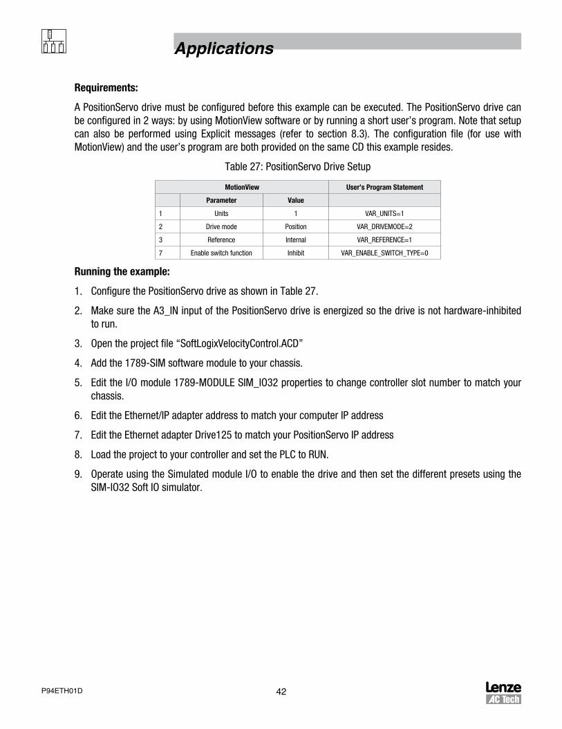
Requirements:
A PositionServo drive must be configured before this example can be executed. The PositionServo drive can be configured in 2 ways: by using MotionView software or by running a short user’s program. Note that setup can also be performed using Explicit messages (refer to section 8.3). The configuration file (for use with MotionView) and the user’s program are both provided on the same CD this example resides.
Table 26: PositionServo Drive Setup
MotionView User’s Program Statement
Parameter Value
1 Units 1 VAR_UNITS=1
2 Drive mode Velocity VAR_DRIVEMODE=1
3 Enable Accel/Decel limits Enable VAR_ENABLEACCELDECEL=1
4 Accel 100 VAR_ACCEL_LIMIT=100
5 Decel 100 VAR_DECEL_LIMIT=100
6 Reference Internal VAR_REFERENCE=1
7 Enable switch function Inhibit VAR_ENABLE_SWITCH_TYPE=0
Running the example:
1. Configure PositionServo drive as shown in Table 26.
2. Make sure the A3_IN input of the PositionServo drive is energized so the drive is not hardware-inhibited to run.
3. Open the project file “SoftLogixVelocityControl.ACD”.
4. Add the 1789-SIM software module to your chassis.
5. Edit the I/O module 1789-MODULE SIM_IO32 properties to change the controller slot number to match your chassis.
6. Edit the Ethernet/IP adapter address to match your computer IP address.
7. Edit the Ethernet adapter Drive125 to match your PositionServo IP address.
8. Load the project to your controller and set the PLC to RUN.
9. Operate using the Simulated module I/O to enable the drive and then set the different presets using the SIM-IO32 Soft IO simulator.

40P94ETH01D
Applications
CMD_Enable
0
1
2
3
4
5
7
Main Routine - Ladder DiagramSoftLogixMSGgen: Main Task: Main ProgramTotal number of rungs in routine: 9
Page 1mm/dd/yyyy hh:mm:ss AM
SoftLogixVelocityControl.ACD
CMD_Enable
PresetInput0<Local:4:I.Data[1].8> PresetVelocityIndex.0
ATTENTION: Set up the drive as follows:Operating mode = VelocityInput Reference = Internal
Use the setup user’s code program
CPTCompute
Dest Drive125:O.Data[0]
0.01Expression
MOVMove
PresetVelocitiesinRPS[PresetVelocityIndex]0.0
Source
RSLogix 5000
SIM_IO_Enable<Local:4:I.Data[1].0>
CMD_Enable
CPTCompute
Dest Drive125:O.Data[0]
0.00Expression
Preset speed control. There are 2 preset inputs on the 1789 simulation I/O.You can replace them with your real I/O or register bits by redefining the alias tags PresetInput0 and Preset Input1.
These two presets give you the choice of 4 preset speeds.
PresetInput1<Local:4:I.Data[1].9> PresetVelocityIndex.1
VelocityReferenceInRPSDest<Drive125:O.Data[1]>
0.0
NOP
Rungs below show velocity alarm implemetation. VelocityActualRPS is an alias for cyclic I/O assembly and is mapped to thedrive’s velocity. The value is in RPS but is multiplied by 60 to get it in RPM then compared with Low or High limits.
CMP
VelocityActualinRPS*60 < 200
Compare
Expression
VelocityLowLimitAlarm<Local:4:O.Data[0].0>
6
Figure 32: Velocity Control Ladder Program

41 P94ETH01D
Applications
8.2 Application Example 2 - IndexingThis application illustrates how to index using an Allen-Bradley PLC and an AC Tech PositionServo drive.
Objective:
This example shows how to use explicit messages to configure indexing parameters and issue indexing commands. I/O messaging (I/O scan) is used to monitor real time data such as status, velocity target and actual position etc.
Equipment:
1. PositionServo drive (firmware revision 3.4 or later)
2. Allen-Bradley PLC SoftLogix (CompactLogix and ControlLogix can be used with modifications to the I/O mapping specific to these models)
3. Ethernet hub or switch
Description:
This example implements a simple indexer. Two inputs of the PLC are used to select the current index and one input is used to start the indexing. All parameters are setup for the desired index using explicit messages. The Start command also uses an explicit message.
PositionServo drives support both explicit and I/O messaging features. In this example, explicit messages are used for configuring and starting the indexing and I/O messaging is used for monitoring the drive status and changing other data like velocity or position.
The PositionServo drive has an Assembly Object (class 0x04) with several instances for Input and Output. Refer to Section 7.2, Assembly Object, for details on the implemetation of assembly objects with the PositionServo. This example uses:
• Assembly #104,105 (input) and #106 (output) are used in this example
• Location 0 of #106 is used to control the drive’s ENABLE/DISABLE state
• Location 1 of #106 is used to set the velocity reference (IREF)
• Location 0 of #105 is used to monitor the actual shaft velocity
42P94ETH01D
Applications
Requirements:
A PositionServo drive must be configured before this example can be executed. The PositionServo drive can be configured in 2 ways: by using MotionView software or by running a short user’s program. Note that setup can also be performed using Explicit messages (refer to section 8.3). The configuration file (for use with MotionView) and the user’s program are both provided on the same CD this example resides.
Table 27: PositionServo Drive Setup
MotionView User’s Program Statement
Parameter Value
1 Units 1 VAR_UNITS=1
2 Drive mode Position VAR_DRIVEMODE=2
3 Reference Internal VAR_REFERENCE=1
7 Enable switch function Inhibit VAR_ENABLE_SWITCH_TYPE=0
Running the example:
1. Configure the PositionServo drive as shown in Table 27.
2. Make sure the A3_IN input of the PositionServo drive is energized so the drive is not hardware-inhibited to run.
3. Open the project file “SoftLogixVelocityControl.ACD”
4. Add the 1789-SIM software module to your chassis.
5. Edit the I/O module 1789-MODULE SIM_IO32 properties to change controller slot number to match your chassis.
6. Edit the Ethernet/IP adapter address to match your computer IP address
7. Edit the Ethernet adapter Drive125 to match your PositionServo IP address
8. Load the project to your controller and set the PLC to RUN.
9. Operate using the Simulated module I/O to enable the drive and then set the different presets using the SIM-IO32 Soft IO simulator.

43 P94ETH01D
Applications
Example Details:
1. The simulated software I/O module 1789-SIM is used to control the application. You can substitute your I/O with one from your taget PLC or create BOOL type tags and use them instead of the I/O to control the application.
2. The I/O are assigned per Table 28.
Table 28: I/O Assignments
I/O # Assignment
0 Drive enable/disable
1 Set motion profile (set accel,decel, max velocity)
2 Executes index
8 Index input 0
9 Index input 1
3. To execute the index, (upon I/O2 engaged) the PLC sends the value of the motion distance from the internal tag to the PositionServo system variable #93 (MOVED) using an explicit message. Writing the value to the variable causes the drive to start to index (relative motion).
4. Before the first move can be executed, I/O1must be activated to set the move parameters such as accel, decel and profile max. velocity. The logic is written in such a way (rung 7) so that the MOVE command will be ignored until all messages for setting up the parameters are executed. This will prevent situations where the index command is issued while setup is in progress.
5. The value of the index is taken from the PLC tag pointed to by I/O8 and 9. The PLC tag allows 4 different indexes.
Feel free to modify this example for the number of indexes needed. The index pointer is in the MotionIndex Selector tag. It holds the index number that will index the motion values array tag, MotionIndexes[]. You can modify the dimension of this array to hold required number of indexes.
Finally variable #93 can be changed to variable #92 and this will execute Absolute position motion. The indexes stored in MotionIndexes[] will then represent the actual position value. Also, variables #177 and #178 can be used instead of variables #93 and #92 (respectively) to create S-curved motion.

44P94ETH01D
Applications
0
1
2
3
4
5
Main Routine - Ladder DiagramSoftLogixMSGgen: Main Task: Main ProgramTotal number of rungs in routine: 11
Page 1mm/dd/yyyy hh:mm:ss AM
SoftLogixIndexing.ACD
CMD_Enable
Motion index selectinput
SIM IO Index0<Local:4:I.Data[1].8> MotionIndexSelector.0
MOV
MotionIndexes[MotionIndexSelector]Move
RSLogix 5000
Drive enableSIM_IO_Enable
<Local:4:I.Data[1].0>
Execute IndexSIM IO MoveD
<Local:4:I.Data[1].2>
Executes MOVED (moveincremental)
CMD_ExecuteMOVED
DATA_MotionProfile.TargetPosition10.0
NOP
This program shows simple indexing. Move indexes. Index0 and Index1 of simulated I/O (inputs 8 and 9 of 1789 soft module)provide a choice of 4 indexes. Indexing starts on positive edge of input 2 (IndexStart). Input 0 is used for the enable and input 1
is used to set the motion profile. The simulated I/O module can be replaced with your hardware by changing the tag’s alias
Set Accel, Decel andprofile velocitycommand input
SIM_IO_SetMoveProfile<Local:4:I.Data[1].1>
Sends new values formove profile to 94P
CNTRL_ChangeAccel
MotionIndexSelector.1
Motion index selectinput
SIM IO Index1<Local:4:I.Data[1].9>
Data for 94P indexmove Target position
to move to
Source
100.0Dest
Figure 33a: Indexing Ladder Diagram

45 P94ETH01D
Applications
Sends new values formove profile to 94P
CNTRL_ChangeAccel
6
7
8
EN
DN
This rung sets the necessary profile ACCEL, DECEL and VELOCITY.
Main Routine - Ladder DiagramSoftLogixMSGgen: Main Task: Main ProgramTotal number of rungs in routine: 11
Page 2mm/dd/yyyy hh:mm:ss AM
SoftLogixIndexing.ACD
Executes MOVED (moveincremental)
CMD_ExecuteMOVED
MSGType - CIP Generic
Message Control Message_SetAcce
MSG
RSLogix 5000
ER . . .
Type - CIP Generic
Message Control Message_SetDecel . . .
EN
DN
ER
MSGType - CIP Generic
Message Control MSG_SetProfileVelocity . . .
EN
DN
ER
ONS
ONS
ONS
This rung sends the message to start motion. Notice if the previous rung was executed to change index motion parameterslike accel, decel, etc., then this rung will not be executed until all messages are cleared.
ONS
MSGType - CIP Generic
Message Control MSG_MOVED . . .
EN
DN
ER
Sends new values formove profile to 94P
CNTRL_ChangeAccel
CPTCompute
Drive125:O.Data[0]
0.01Expression
Dest
CMD_Enable
Drive125:S.Data[0].0
MSG_SetProfileVelocity.DNMSG_SetDecel.DNMSG_SetAccel.DN
StorageBits registerfor ONS instructions
StorageBits.3
StorageBits registerfor ONS instructions
StorageBits.0
StorageBits registerfor ONS instructions
StorageBits.1
StorageBits registerfor ONS instructions
StorageBits.2
Figure 33b: Indexing Ladder Diagram, Page 2

46P94ETH01D
Applications
Drive’s Status flagSet when motion is
completedMotion Completed
<Drive 125:S.Data[0].24>
9
10
(End)
Main Routine - Ladder DiagramSoftLogixMSGgen: Main Task: Main ProgramTotal number of rungs in routine: 11
Page 3mm/dd/yyyy hh:mm:ss AM
SoftLogixIndexing.ACD
CPTCompute
Drive125:O.Data[0]
0.00Expression
Dest
CMD_Enable
Local:4:O.Data[0].1
RSLogix 5000
Figure 33c: Indexing Ladder Diagram, Page 3

47 P94ETH01D
Applications
8.3 Application Example 3 - Configuration Using Explicit MessagesThis application illustrates how to configure a PositionServo drive using explicit messages.
Objective:
This example shows how to configure a PositionServo drive by sending a list of explicit messages.
Equipment:
1. PositionServo drive (firmware revision 3.4 or later)
2. Allen-Bradley PLC SoftLogix (CompactLogix and ControlLogix can be used with modifications to the I/O mapping specific to these models)
3. Ethernet hub or switch
Description:
This example implements a state machine which sends a list of predefined messages to the PositionServo drive. Since the sending a message process inside the PLC takes few steps, the message is sent successfully when the MSG instruction returns the status. The operation of the rest of the logic in PLC program usually depends upon result of the MSG operation. In a situation where multiple messages need to be sent, redundant status handling logic multiplies and complicates the overall PLC program. This example illustrates a practical example of the usage of multiple configuration messages. The velocity control program from Application Example 1 (section 8.1) will be used.
Recall that the PositionServo drive needs to be configured ahead of time to be used in Example 1. The drive’s mode, accel, decel and other parameters need to be configured by using MotionView software or by writing a short user’s program. We will modify the PLC program in such a way that the configuration is performed directly from the PLC.
To do this create a MSG instruction and configure it with the PositionServo drive address, Class 0x64 (PositionServo variables class) and the CIP table operation SetAttributeSingle. Create two arrays – one holding instances of the class (i.e system variables IDs) and the other array will hold VALUES that the drive’s variables will be set to.
Then execute the MSG instruction as many times as there are number of variables to set, each time setting the MSG instruction INSTANCE with the value from the list. The ‘value to send’ (actual data) will be copied from the second array to the designated tag that the MSG instruction Source Data field is pointed too.
RSLogix 5000 File:
For this Application Example open the project file “SoftLogixConfigurationMessages.ACD” (on CD).

48P94ETH01D
Applications
The simulate I/O module is used to provide inputs as follows:0 - enable/disable2 - configure drive4 - drive fault reset
8 - PresetInput09 - PresetInput1
0
1
This example shows how to control the 94P drive in velocity mode using I/O messaging. It also shows an exampleof how to use an explicit message to configure the drive prior to using it. Explicit messages are grouped to the list
and sent sequentially. Refer to ExecuteMSGlist for details. Any list of messages can be constructed using this routine.
Main Routine - Ladder DiagramSoftLogixMSGgen: Main Task: Main ProgramTotal number of rungs in routine: 17
Page 1mm/dd/yyyy hh:mm:ss PM
SoftLogixConfigurationMessages.ACD
Configure<Local:4:I.Data[1].2>
RSLogix 5000
NOPThis rung initialises the message list in the memory
JSRJump To Subroutine
ExecuteMSGlist
1Input Par
Routine Name
CMD_Enable
S:SF
CPTCompute
Drive125:O.Data[0]
0.01Expression
Dest
2
3
4
5
Activating StartConfiguration sends the list of explicit messages configured by the previous rung.Messages list
control structureConfig_list.List_Start
JSRJump To Subroutine
ExecuteMSGlist
Input Par
Routine Name
This subroutine implements the state machine which sends the messages to the 94P.
0
6
ConfigOK_LED<Local:4:O.Data[0].8>
Messages listcontrol structure
Config_list.ListDone
Enables the drive. If configuration was issued, the drive cannot be enabled until the list of configuration messages is completed.
SIM IO Enable<Local:4:I.Data[1].0>
Messages listcontrol structure
Config_list.ListDone
Implements Enable/Disable by changing the value in the output assembly. A non-0 value (true) will enable the drive.A 0 value (false) will disable the drive.
CMD_Enable
Figure 34a: Explicit Messages Ladder Diagram Page 1
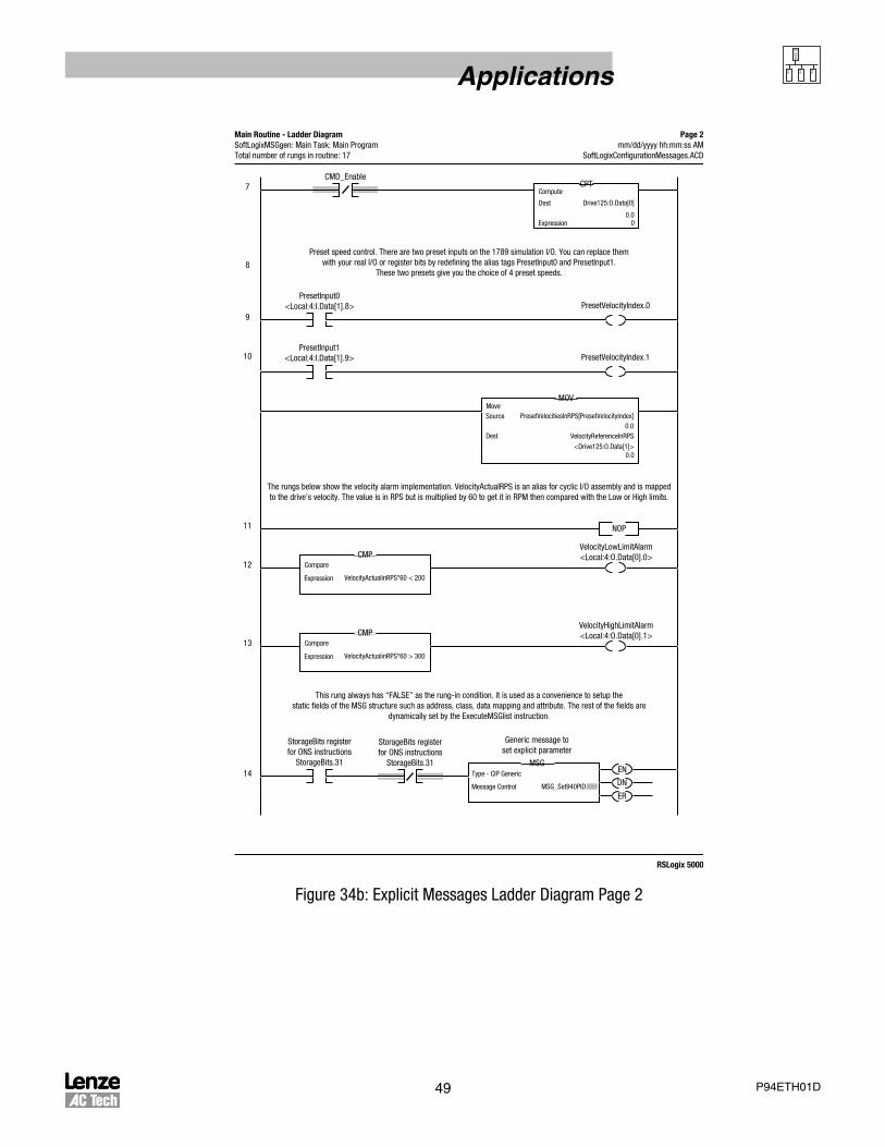
49 P94ETH01D
Applications
7
8
9
10
11
12
Main Routine - Ladder DiagramSoftLogixMSGgen: Main Task: Main ProgramTotal number of rungs in routine: 17
Page 2mm/dd/yyyy hh:mm:ss AM
SoftLogixConfigurationMessages.ACD
PresetInput0<Local:4:I.Data[1].8> PresetVelocityIndex.0
MOV
PresetVelocitiesInRPS[PresetVelocityIndex]Move
RSLogix 5000
StorageBits registerfor ONS instructions
StorageBits.31
VelocityReferenceInRPS0.0
Preset speed control. There are two preset inputs on the 1789 simulation I/O. You can replace themwith your real I/O or register bits by redefining the alias tags PresetInput0 and PresetInput1.
These two presets give you the choice of 4 preset speeds.
The rungs below show the velocity alarm implementation. VelocityActualRPS is an alias for cyclic I/O assembly and is mappedto the drive’s velocity. The value is in RPS but is multiplied by 60 to get it in RPM then compared with the Low or High limits.
Source
Dest
PresetInput1<Local:4:I.Data[1].9> PresetVelocityIndex.1
CPTCompute
Drive125:O.Data[0]
0.00Expression
Dest
0.0<Drive125:O.Data[1]>
NOP
VelocityLowLimitAlarm<Local:4:O.Data[0].0>CMP
VelocityActualinRPS*60 < 200
Compare
Expression
CMP
VelocityActualinRPS*60 > 300
Compare
Expression
VelocityHighLimitAlarm<Local:4:O.Data[0].1>
This rung always has “FALSE” as the rung-in condition. It is used as a convenience to setup thestatic fields of the MSG structure such as address, class, data mapping and attribute. The rest of the fields are
dynamically set by the ExecuteMSGlist instruction.
13
14MSG
Type - CIP Generic
Message Control MSG_Set940PID . . .
EN
DN
ER
StorageBits registerfor ONS instructions
StorageBits.31
CMD_Enable
Generic message toset explicit parameter
Figure 34b: Explicit Messages Ladder Diagram Page 2

50P94ETH01D
Applications
15
16
(End)
Main Routine - Ladder DiagramSoftLogixMSGgen: Main Task: Main ProgramTotal number of rungs in routine: 17
Page 3mm/dd/yyyy hh:mm:ss AM
SoftLogixConfigurationMessages.ACD
CMD FaultReset<Local:4:I.Data[1].4>
RSLogix 5000
Status_DriveFault<Drive125:S.Data[0].1>
CPTCompute
TrueValue
01Expression
Dest
MSGType - CIP Generic
Message Control MSG_940ResetFault . . .
EN
DN
ER
Drive_Fault_LED<Local:4:O.Data[0].16>
Figure 34c: Explicit Messages Ladder Diagram Page 3

51 P94ETH01D
Applications
ListLength
Size: 184 byte(s)
SoftLogixMSGgen - User Defined Data TypeSoftLogixMSGgen (Controller)
Page 1mm/dd/yyyy hh:mm:ss AM
SoftLogixConfigurationMessages.ACD
Description:
RSLogix 5000
Data type Name: Msg_List_Control
Messages list control structure
Name Data Type Style Description
MsgIndex
ListDone
ListErr
List_instance
List_Value
List_CurrentValue
List_latch
List_Start
DINT
DINT
DINT
DINT[20]
State
BOOL
BOOL
BOOL
REAL[20]
REAL
BOOL
Decimal
Decimal
Decimal
Decimal
Decimal
Decimal
Decimal
Decimal
Float
Float
Figure 35: User’s Defined Type for Meassage List Control
Rung 1
At the first scanner call to subroutine, ExecuteMSGlist with argument = 1 initialises the list of explicit messages. Refer to the routine in this section. The list of messages is kept in tag Config_List of the user’s defined type (Figure 34a). The tag has 2 arrays inside: List_instance[] and List_value[]. These arrays will hold pairs of instances-value when the MSG instruction fields are configured for the next send.
Rung 2,3
When I/O2 is triggered, ExecuteMSGlist gets called with argument = 0. This starts the state machine (if transmission is not already in progress) and transmits messages from the list one by one. Calling the subroutine does not stop the scanning but merely starts the transmission of the next message from the list if the previous one has already been sent until the list is not over. Transmission of the message happens in the background without waiting until message TX is completed.

52P94ETH01D
Applications
Rung 4
Indicates on the I/O that the full configuration list is done. This status interlocks rung 5 to prevent the ENABLE command before configuration is completed.
Rung 5-13,15
Same as in original example.
Rung 14
This rung is a “Convenience” entry. This rung never becomes true. It is needed to configure the MSG instruction field with constants (drive address, message type etc.). The instance field is changed by the ExecuteMSGlist routine according to the value in the list.
User’s defined type for messages list control:
ExecuteMSGlist routine source code//This is sub program sends sequence of messages//This routine is useful for configuration sequences.SBR(InitList);
IF InitList THEN //Initialisation state. List of messages initialized
//0 Drive mode - velocity Config_list.List_instance[0] :=34; Config_list.List_Value[0] :=1;//1 Reference source - internal Config_list.List_instance[1] :=37; Config_list.List_Value[1] :=1;//2 Enable switch type - Inhibit only Config_list.List_instance[2] :=29; Config_list.List_Value[2] :=0;//3 Enable Accel/Decel Config_list.List_instance[3] :=75; Config_list.List_Value[3] :=1;//4 Set accel limit for velocity mode Config_list.List_instance[4] :=76; Config_list.List_Value[4] :=1000;//5 Set decel limit for velocity mode Config_list.List_instance[5] :=77; Config_list.List_Value[5] :=1000;
//--Total number of messages = 6 Config_list.ListLength:=6; //reset state to IDLE (==0) Config_list.State:=0;
ELSE

53 P94ETH01D
Applications
CASE Config_list.State of
0: //it is idle state , just return If Config_list.List_Start AND NOT Config_list.List_latch then Config_list.State:=1; END_IF; Config_list.List_latch:=Config_list.List_Start;
1: //State Start Config_list.MsgIndex :=0; //reset index Config_list.ListDone:=0; //reset DONE flag Config_list.ListErr:=0; //reset error flag MSG_Set940PID.Instance:=Config_list.List_instance[Config_list.MsgIndex]; //this is normally should be done in state2 Config_list.List_CurrentValue:=Config_list.List_Value[Config_list.MsgIndex];//but redundant here so we don’t have to wait for next loop MSG(MSG_Set940PID); //send first message Config_list.State:=2; //advance current state to TX
2: //State TX if MSG_Set940PID.DN Then //message sent so advance index and check if it is not over yet Config_list.MsgIndex:=Config_list.MsgIndex+1; //advance index in the list if Config_list.MsgIndex <= (Config_list.ListLength-1) then MSG_Set940PID.Instance:=Config_list.List_instance[Config_list.MsgIndex]; Config_list.List_CurrentValue:=Config_list.List_Value[Config_list.MsgIndex]; MSG(MSG_Set940PID); else Config_list.ListDone:=1; Config_list.State:=0; end_if; elsif MSG_Set940PID.ER then Config_list.State:=0; Config_list.ListErr:=1; END_IF;END_CASE;
END_IF;

54P94ETH01D
Applications
8.4 Application Note - Detection of EtherNet/IP Exclusive Ownership LossThe PositionServo provides bits in the extended status register to detect a loss of exclusive ownership over EtherNet/IP. The user can use these bits in a logical program to detect this condition and take action as necessary for their application, such as to prevent a runaway condition in velocity or torque mode. Here is an example of PositionServo indexer logic to perform this:
PROGRAM_START:
IF (!(VAR_EXSTATUS & (0x1000000))) ; checks if Exclusive ownership is lost
DISABLE ; in case of EIP exclusive ownership loss, disable drive
ENDIF
GOTO PROGRAM_START
END

Lenze AC Tech Corporation630DouglasStreet•Uxbridge,MA01569•USASales:800217-9100•Service:508278-9100
www.lenzeamericas.com
P94ETH01D