Embed Size (px)
Citation preview
POSITION CONTROL FOR INDUCTIONMOTORS USING THE SLIDING MODE
CONTROL THEORY
Oscar Barambones ∗,1, Patxi Alkorta ∗∗,Jose Marıa Gonzalez de Durana ∗, Jose Antonio Ramos ∗∗∗
∗ Dpto. Ingenierıa de Sistemas y Automatica EUI de Vitoria. Nieves Cano 12.01006 Vitoria, Spain.
∗∗ Dpto. Ingenierıa de Sistemas y Automatica EUITI de Eibar. Avda. Otaola,29. 20600 Eibar, Spain.
∗∗∗ Dpto. Ingenierıa Electrica EUI de Vitoria.
Abstract: A sliding mode position control for induction motors using field oriented control theoryis presented. The proposed controller provides global asymptotic position tracking in the presence ofunknown parameters and load torque variations. The proposed design incorporates a flux estimator thatoperates on the principle of flux and current observer. The proposed observer is basically an estimatorthat uses a plant model and a feedback loop with measured stator voltages and currents. The stabilityanalysis of the proposed controller under parameter uncertainties and load disturbances is providedusing the Lyapunov stability theory. Finally simulated and experimental results show that the proposedcontroller with the proposed observer provides high-performance dynamic characteristics and that thisscheme is robust with respect to plant parameter variations and external load disturbances. CopyrightCONTROLO 2012.
Keywords: Robust Control, Position Control, Induction Machines. Field Oriented Control. SlidingMode Control.
1. INTRODUCTION
AC induction motors have been widely used in industrial ap-plications such machine tools, steel mills and paper machinesowing to their good performance provided by their solid ar-chitecture, low moment of inertia, low ripple of torque andhigh initiated torque. Some control techniques have been de-veloped to regulate these induction motors servo drives in high-performance applications. One of the most popular technique isthe indirect field oriented control method (Vas 1994).
The field-oriented technique guarantees the decoupling oftorque and flux control commands of the induction motor, sothat the induction motor can be controlled linearly as a sepa-rated excited D.C. motor. However, the control performance ofthe resulting linear system is still influenced by uncertainties,which usually are composed of unpredictable parameter varia-tions, external load disturbances, and unmodelled and nonlineardynamics. Therefore, many studies have been made on themotor drives in order to preserve the performance under theseparameter variations and external load disturbance, such asnonlinear control, optimal control, predictive control, variablestructure system control, adaptive control, fuzzy control andneural control (Utkin 1993; Cirrincione 2007; Orlowska 2010;Miranda 2009).
Position control is often used in some applications of electricaldrives like robotic systems, conveyor belts, etc. In these appli-
1 The authors are very grateful to the Basque Government by the support ofthis work through the project SAIOTEK and to the UPV/EHU by its supportthrough project GUI10/01.
cations uncertainty and external disturbances are present andtherefore a robust control system that maintain the desired con-trol performance under this situations are frequently required(Cecati 2000).
The sliding-mode control strategy has been focussed on manystudies and research for the position control of the inductionmotors (Benchaib 2000; Wang 2005, Barambones 2007).
On the other hand in the last decade remarkable efforts havebeen made to reduce the number of sensors in the controlsystems. The sensors increase the cost and also reduces thereliability of the control system because these elements aregenerally expensive, delicate and difficult to instal (Ghanes2009; Comanescu 2009).
This paper presents a variable structure vector control schemeconsisting, on the one hand of a flux estimation algorithm in or-der to avoid the flux sensors, and on the other hand, of a variablestructure control algorithm that overcome the system uncertain-ties and load disturbances. Moreover, the proposed controllerdo not present a high computational cost and therefore can beimplemented easily in a real time applications. In this sense, thecontrol scheme presented in this paper is validated in a real testusing a commercial induction motor in order to demonstrate theperformance of this controller.
This manuscript is organized as follows. The flux observer isintroduced in Section 2. Then, the proposed variable structurerobust position control is presented in Section 3. In the Section4, some simulation and experimental results are presented.Finally, concluding remarks are stated in Section 5.
10th Portuguese Conference on Automatic Control16-18 July 2012
CONTROLO’2012Funchal, Portugal
81
2. ROTOR FLUX ESTIMATOR
Many schemes based on simplified motor models have beendevised to estimate some internal variables of the inductionmotor from measured terminal quantities (Bose 2001). Thisprocedure is frequently used in order to avoid the presenceof some sensors in the control scheme. In order to obtain anaccurate dynamic representation of the motor, it is necessaryto base the calculation on the coupled circuit equations of themotor.
Since the motor voltages and currents are measured in a sta-tionary frame of reference, it is also convenient to express theinduction motor dynamical equations in this stationary frame.
The system state space equations can be written in the form(Barambones 2008):
x = Ax+B vs (1)
where
x= [ids iqs ψdr ψqr]T
vs = [vds vqs 0 0]T
B =
1
σLs0 0 0
01
σLs0 0
T
A=
−ρ 0Rr
cLr
wr
c
0 −ρ −wr
c
Rr
cLr
LmRr
Lr0 −Rr
Lr−wr
0LmRr
Lrwr −Rr
Lr
where σ = 1 − L2m
LrLs, ρ =
L2mRr + L2
rRs
σLsL2r
, c =σLsLr
Lm.
Considering the stator currents as the system output, the outputequation for this system is:
y = C x (2)
where
C =
[1 0 0 00 1 0 0
]
Then, the states observer, which estimates the system states(stator current and rotor flux), is defined by means of thefollowing equation (Luenberger observer):
˙x=Ax+Bvs +G (y − Cx) (3)
=Ax+Bvs +GC(x− x) (4)
where the symbol (·) represents the estimated values and G isthe observer gain matrix.
Therefore, if the observer gain G is chosen such that thecharacteristic equation of the matrix A − GC has all its roots
with a negative real part, then the estimation error convergesto zero. Consequently the estimated states ids, iqs, ψds, ψqs
converges to the real states ids, iqs, ψds, ψqs as t tends toinfinity. Hence, the rotor flux may be obtained from the stateobserver given by equation (3).
3. VARIABLE STRUCTURE ROBUST POSITIONCONTROL
The mechanical equation of an induction motor can be writtenas:
Jθm +Bθm + TL = Te (5)
where J and B are the inertia constant and the viscous frictioncoefficient of the induction motor respectively; TL is the exter-nal load; θm is the rotor mechanical position, which is relatedto the rotor electrical position, θr, by θm = 2 θr/p where pis the pole numbers and Te denotes the generated torque of aninduction motor, defined as (Bose 2001):
Te =3p
4
Lm
Lr(ψe
drieqs − ψe
qrieds) (6)
where ψedr and ψe
qr are the rotor-flux linkages, with the sub-script ‘e’ denoting that the quantity is refereed to the syn-chronously rotating reference frame; ieqs and ieds are the statorcurrents, and p is the pole numbers.
The relation between the synchronously rotating referenceframe and the stationary reference frame is performed by theso-called reverse Park’s transformation.
The estimated angular position of the rotor flux vector (ψr)related to the d-axis of the stationary reference frame maybe calculated by means of the rotor flux components in thisreference frame ( ψdr, ψqr) as follows:
θe = arctan
(ψqr
ψdr
)(7)
where θe is the estimated angular position of the rotor fluxvector.
Using the field-orientation control principle (Bose 2001), thecurrent component ieds is aligned in the direction of the rotorflux vector ψr, and the current component ieqs is aligned in theperpendicular direction to it. At this condition, it is satisfiedthat:
ψeqr = 0, ψe
dr = |ψr| (8)
Taking into account the results presented in equation (8), theequation of induction motor torque (6) is simplified to:
Te =3p
4
Lm
Lrψe
drieqs = KT i
eqs (9)
where KT is the torque constant, defined as follows:
KT =3p
4
Lm
Lrψe∗
dr (10)
where ψe∗dr denotes the command rotor flux.
82
With the above mentioned proper field orientation, the dynam-ics of the rotor flux is given by:
dψedr
d t+ψe
dr
Tr=Lm
Trieds (11)
Then, the mechanical equation (5) becomes:
θm + a θm + f = b ieqs (12)
where the parameter are defined as:
a =B
J, b =
KT
J, f =
TL
J; (13)
Now, we are going to consider the previous mechanical equa-tion (12) with uncertainties as follows:
θm = −(a+ △a)θm − (f + △f) + (b+ △b)ieqs (14)
where the terms △a, △b and △f represents the uncertaintiesof the terms a, b and f respectively.
Let us define the position tracking error as follows:
e(t) = θm(t) − θ∗m(t) (15)
where θ∗m is the rotor position command.
Taking the second derivative of the previous equation withrespect to time yields:
e(t) = θm − θ∗m = −a e(t) + u(t) + d(t) (16)
where the following terms have been collected in the signalu(t),
u(t) = b ieqs(t) − a θ∗m(t) − f(t) − θ∗
m(t) (17)
and the uncertainty terms have been collected in the signal d(t),
d(t) = −△awm(t) − △f(t) + △b ieqs(t) (18)
Now, we are going to define the sliding variable S(t) as:
S(t) = e(t) + k e(t) (19)
where k is a positive constant gain.
Then, the sliding surface is defined as:
S(t) = e(t) + k e(t) = 0 (20)
The variable structure position controller is designed as:
u(t) = −(k − a) e(t) − β sgn(S) (21)
where the k is the previously defined gain, β is the switchinggain, S is the sliding variable defined in eqn. (19) and sgn(·) isthe sign function.
In order to obtain the position trajectory tracking, the followingassumption should be formulated:
(A 1) The gain β must be chosen so that β ≥ dwhere d ≥ supt∈R0+ |d(t)|.
Note that this condition only implies that the system uncertain-ties are bounded magnitudes.
Theorem 1. Consider the induction motor given by equation(14). Then, if the assumption (A 1) are verified, the controllaw (21) leads the rotor mechanical position θm(t) so that theposition tracking error e(t) = θm(t) − θ∗
m(t) tends to zero asthe time tends to infinity.
The proof of this theorem can be carried out using the Lya-punov stability theory using the following Lyapunov function(Barambones 2011).
V (t) =1
2S(t)S(t) (22)
Using the Lyapunov’s direct method, since V (t) is clearlypositive-definite, V (t) is negative definite and V (t) tends toinfinity as S(t) tends to infinity, then the equilibrium at theorigin S(t) = 0 is globally asymptotically stable. ThereforeS(t) tends to zero as the time t tends to infinity. Moreover, alltrajectories starting off the sliding surface S = 0 must reachit in finite time and then they will remain on this surface. Thissystem’s behavior, once on the sliding surface is usually calledsliding mode.
When the sliding mode occurs on the sliding surface (20),then S(t) = 0, and therefore the dynamic behavior of thetracking problem (16) is equivalently governed by the followingequation:
S(t) = 0 ⇒ e(t) = −k e(t) (23)
Then, like k is a positive constant, the tracking error e(t) andits derivative e(t) converges to zero exponentially.
Finally, the torque current command, ie∗qs(t), can be obtained
directly substituting eqn. (21) in eqn. (17):
ie∗qs(t) =
1
b
[−(k − a) e− β sgn(S) + a θ∗
m + θ∗m + f(t)
](24)
Therefore, the proposed variable structure control resolves theposition tracking problem for the induction motor in pres-ence of some uncertainties in mechanical parameters and loadtorque.
4. SIMULATION AND EXPERIMENTAL RESULTS
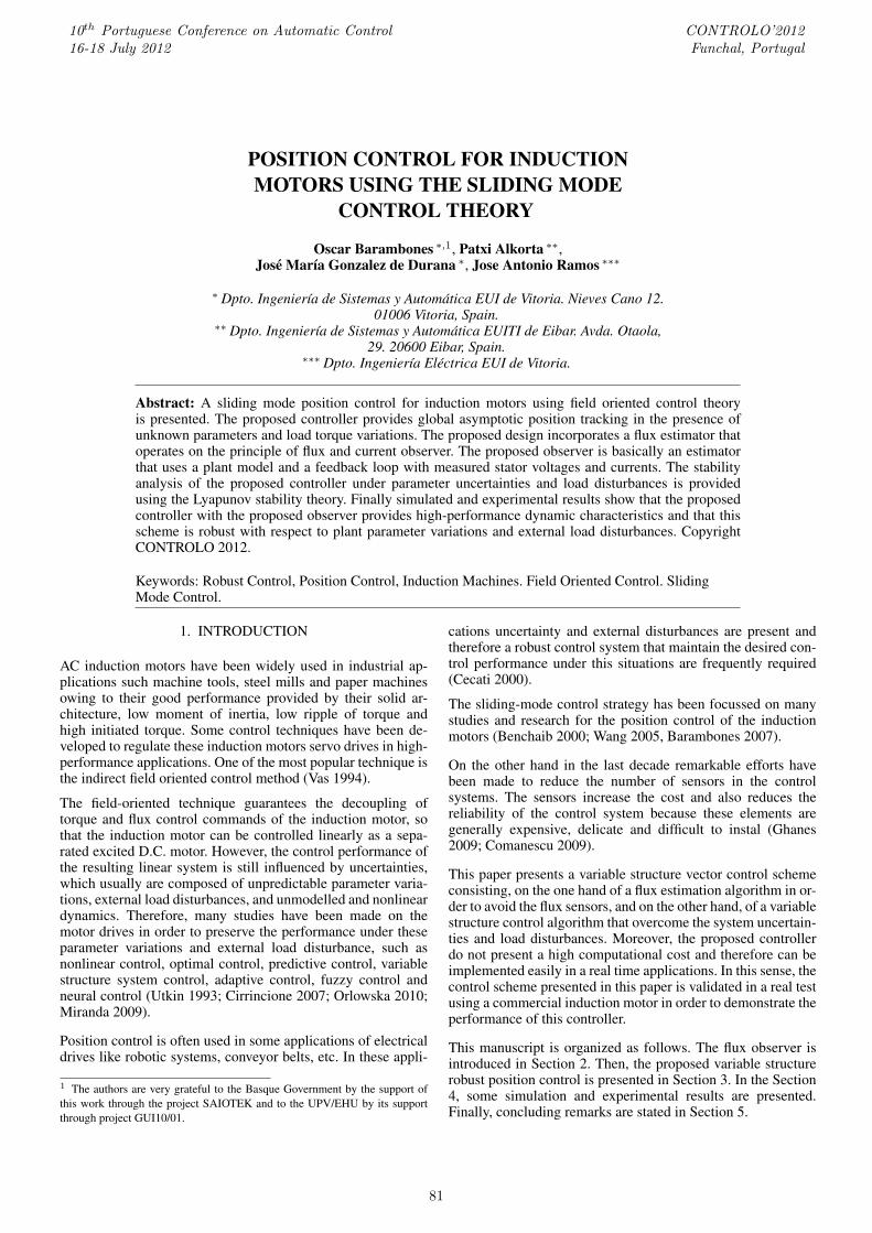
In this section we will study the position regulation perfor-mance of the proposed sliding-mode field oriented control ver-sus reference and load torque variations by means of simulationexamples. The block diagram of the proposed robust positioncontrol scheme is presented in Figure 1 and the function of theblocks that appear in this figure are explained below: The block‘VSC Controller’ represents the proposed sliding-mode con-troller, and it is implemented by equations (19) and (24). Theblock ‘limiter’ limits the current applied to the motor windingsso that it remains within the limit value, being implementedby a saturation function. The block ‘dqe → abc’ makes theconversion between the synchronously rotating and stationaryreference frames (Park’s Transformation). The block ‘CurrentController’ consists of a SVPWM current control. The block‘SVPWM Inverter’ is a six IGBT-diode bridge inverter with540 V DC voltage source. The block ‘Field Weakening’ givesthe flux command based on rotor speed, so that the PWM con-troller does not saturate. The block ‘ie∗
ds Calculation’ providesthe current reference ie∗
ds from the rotor flux reference throughthe equation (11). The block ’Flux Estimator’ represents the
83
θe
Calculation
dqe → abc CurrentController
ψqr
6
-VSC
Controller-
Limiter-
�
SVPWMInverter
IM
-
?
?
6iabc
�
ψdr
θe
vabc
FieldWeakening
ie∗ds
Calculation-
-
ie∗qs
ie∗ds
ψe∗dr
--
Flux Estimators-
θ∗m
-
ie∗qs
−+ e
6
i∗abc
Pulses
6
6
θm
θm
wm
Fig. 1. Block diagram of the proposed sliding-mode field oriented control
proposed Fux estimator, and it is implemented by the equation(3). The block ‘θe Calculation’ provides the angular positionof the rotor flux vector. Finally, the block ‘IM’ represents theinduction motor.
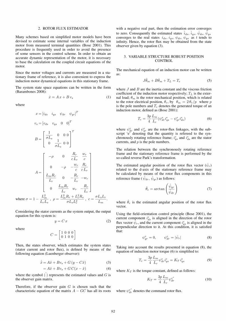
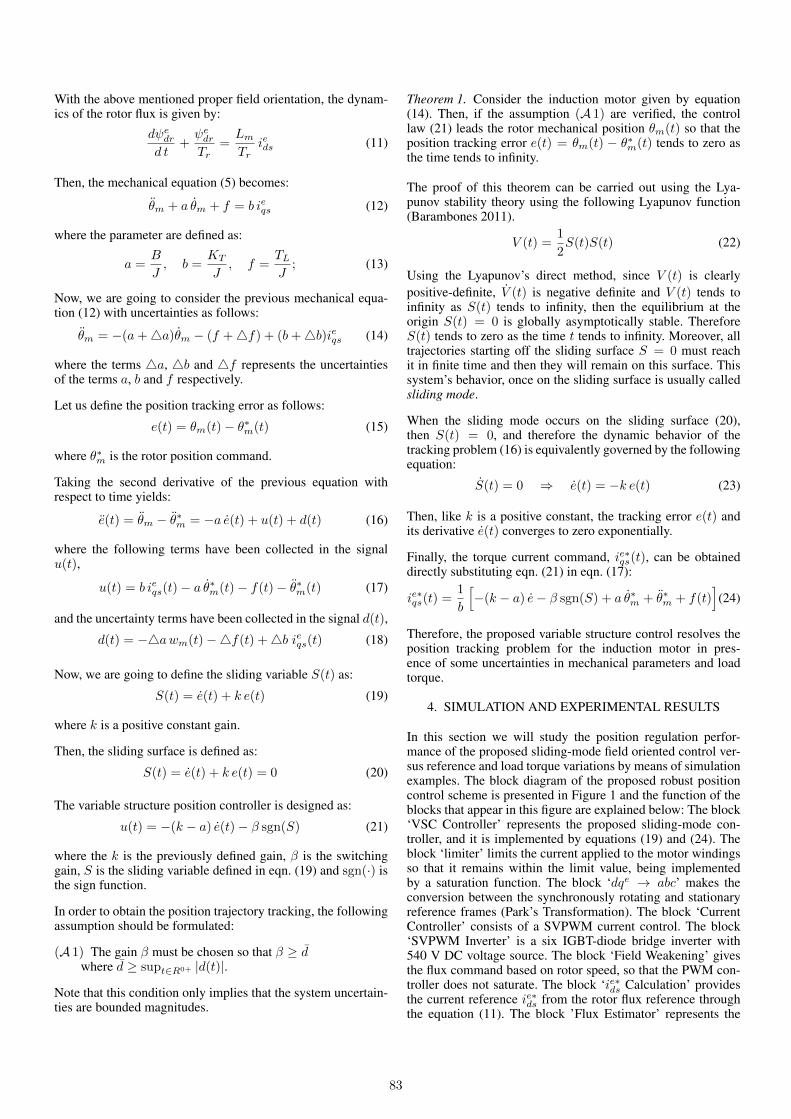
In order to carry out the real experimental validation of theproposed control scheme, it is used the control platform showin figure 2. The block diagram of this experimental platform isshown in figure 3.
Fig. 2. Induction motor experimental platform
This control platform allows to verify the real time performanceof the induction motor controls in a real induction motor. Theplatform is formed by a PC with Windows XP in which itis installed MatLab7/Simulink R14 and ControlDesk 2.7 and
Fig. 3. Block diagram of the induction motor experimentalplatform
the DS1103 Controller Board real time interface of dSpace.The power block is formed of a three-phase rectifier connectedto 380 V/50 Hz AC electrical net and a capacitor bank of27.200 µF in order to get a DC bus of 540 V. The platformalso includes a three-phase IGBT/Diode bridge of 50A, andthe M2AA 132M4 ABB induction motor of 7.5kW of die-castaluminium squirrel-cage type and 1440 rpm, with the followingparameters:
• Rs, stator resistance, 0.81• Rr, rotor resistance, 0.57• Lm, magnetizing inductance, 0.117774 mH• Ls, stator inductance, 0.120416 mH• Lr, rotor inductance, 0.121498 mH• p, number of poles, 4• J , moment of inertia, 0.057 kg m2• B, viscous friction coefficient, 0.015 Nm/(rad/s)• αAl, temperature coefficient of Aluminium, 0.0039K−1
The rotor speed of this motor is measured using the G1BWGLDBILTN incremental rotary encoder of 4096 square impulses perrevolution. The platform also includes a 190U2 Unimotor syn-chronous AC servo motor of 10.6 kW connected to the induc-
84
tion motor to generate the load torque (controlled in torque).This servo motor is controlled by its VSI Unidrive invertermodule.
The sample time used to realize the real implementation of thethe position control is 100µs, and the processor used for the realtests is a floating point PowerPC at 1MHz, located in the realtime DS1103 hardware of dSpace. This target incorporates theTMS320F240 DSP working as slave to generate the SVPWMpulses for the inverter. Finally, the position and currents con-trol algorithms, the θe angle and flux estimator, the SVPWMcalculations, and the Park’s transformations have been realizedin C programming language in a unique S-Builder module ofSimulink, in order to obtain a compact and portable code.
In the experimental validation it is assumed that there is anuncertainty around 50 % in the system mechanical parame-ters, that will be overcome by the proposed variable structurecontrol. The electromagnetic torque current command, i∗sq , hasbeen limited to 20 A, in order to provide a protection againstovercurrents in the induction motor’s stator fed. Finally, thefrequency of commutation of VSI module of the platform islimited to 8 kHz.
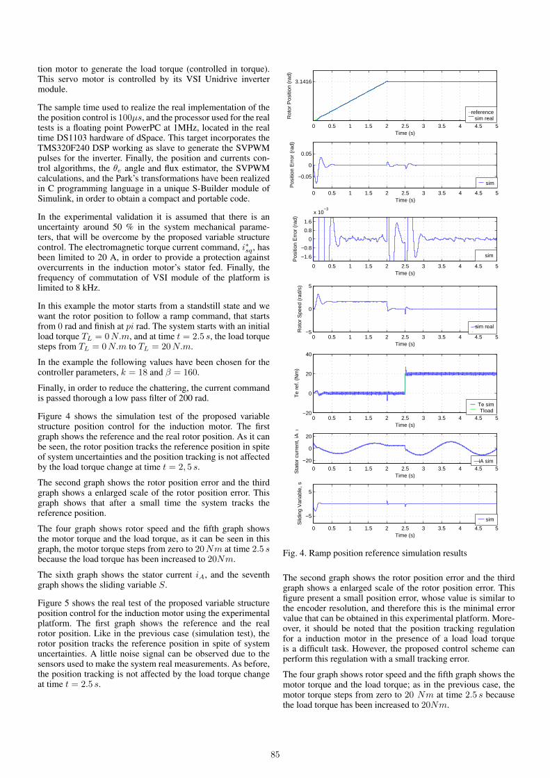
In this example the motor starts from a standstill state and wewant the rotor position to follow a ramp command, that startsfrom 0 rad and finish at pi rad. The system starts with an initialload torque TL = 0N.m, and at time t = 2.5 s, the load torquesteps from TL = 0N.m to TL = 20N.m.
In the example the following values have been chosen for thecontroller parameters, k = 18 and β = 160.
Finally, in order to reduce the chattering, the current commandis passed thorough a low pass filter of 200 rad.
Figure 4 shows the simulation test of the proposed variablestructure position control for the induction motor. The firstgraph shows the reference and the real rotor position. As it canbe seen, the rotor position tracks the reference position in spiteof system uncertainties and the position tracking is not affectedby the load torque change at time t = 2, 5 s.
The second graph shows the rotor position error and the thirdgraph shows a enlarged scale of the rotor position error. Thisgraph shows that after a small time the system tracks thereference position.
The four graph shows rotor speed and the fifth graph showsthe motor torque and the load torque, as it can be seen in thisgraph, the motor torque steps from zero to 20Nm at time 2.5 sbecause the load torque has been increased to 20Nm.
The sixth graph shows the stator current iA, and the seventhgraph shows the sliding variable S.
Figure 5 shows the real test of the proposed variable structureposition control for the induction motor using the experimentalplatform. The first graph shows the reference and the realrotor position. Like in the previous case (simulation test), therotor position tracks the reference position in spite of systemuncertainties. A little noise signal can be observed due to thesensors used to make the system real measurements. As before,the position tracking is not affected by the load torque changeat time t = 2.5 s.
0 0.5 1 1.5 2 2.5 3 3.5 4 4.5 5
3.1416
Time (s)
Rot
or P
ositi
on (
rad)
referencesim real
0 0.5 1 1.5 2 2.5 3 3.5 4 4.5 5
−0.05
0
0.05
Time (s)
Pos
ition
Err
or (
rad)
sim
0 0.5 1 1.5 2 2.5 3 3.5 4 4.5 5
−1.6
−0.8
0
0.8
1.6
x 10−3
Time (s)
Pos
ition
Err
or (
rad)
sim
0 0.5 1 1.5 2 2.5 3 3.5 4 4.5 5−5
0
5
Time (s)
Rot
or S
peed
(ra
d/s)
sim real
0 0.5 1 1.5 2 2.5 3 3.5 4 4.5 5−20
0
20
40
Time (s)
Te
ref.
(Nm
)
Te simTload
0 0.5 1 1.5 2 2.5 3 3.5 4 4.5 5
−20
0
20
Time (s)
Sta
tor
curr
ent,
iA (
A)
iA sim
0 0.5 1 1.5 2 2.5 3 3.5 4 4.5 5
−5
5
Time (s)
Slid
ing
Var
iabl
e, s
sim
Fig. 4. Ramp position reference simulation results
The second graph shows the rotor position error and the thirdgraph shows a enlarged scale of the rotor position error. Thisfigure present a small position error, whose value is similar tothe encoder resolution, and therefore this is the minimal errorvalue that can be obtained in this experimental platform. More-over, it should be noted that the position tracking regulationfor a induction motor in the presence of a load load torqueis a difficult task. However, the proposed control scheme canperform this regulation with a small tracking error.
The four graph shows rotor speed and the fifth graph shows themotor torque and the load torque; as in the previous case, themotor torque steps from zero to 20 Nm at time 2.5 s becausethe load torque has been increased to 20Nm.
85

0 0.5 1 1.5 2 2.5 3 3.5 4 4.5 50
3.1416
Time (s)
Rot
or P
ositi
on (
rad)
referenceexp real
0 0.5 1 1.5 2 2.5 3 3.5 4 4.5 5
−0.05
0
0.05
Time (s)
Pos
ition
Err
or (
rad)
exp
0 0.5 1 1.5 2 2.5 3 3.5 4 4.5 5
−1.6
−0.8
0
0.8
1.6
x 10−3
Time (s)
Pos
ition
Err
or (
rad)
exp
0 0.5 1 1.5 2 2.5 3 3.5 4 4.5 5−5
0
5
Time (s)
Rot
or S
peed
(ra
d/s)
exp real
0 0.5 1 1.5 2 2.5 3 3.5 4 4.5 5−20
0
20
40
Time (s)
Te
(Nm
)
Te expTload
0 0.5 1 1.5 2 2.5 3 3.5 4 4.5 5
−20
0
20
Time (s)
Sta
tor
curr
ent,
iA (
A)
iA exp
0 0.5 1 1.5 2 2.5 3 3.5 4 4.5 5
−5
0
5
Time (s)
Slid
ing
Var
iabl
e, s
exp
Fig. 5. Ramp position reference experimental results
The sixth graph shows the stator current iA, and the seventhgraph shows the sliding variable S.
5. CONCLUSIONS
In this paper a robust position regulation for an induction mo-tors using a sliding mode vector control has been presented. It isalso proposed a flux estimator that overcomes the flux sensors.The flux estimation algorithm is based on a Luenberger ob-server and employs the measured stator voltages and currents inthe stationary reference frame. The proposed control scheme donot present a high computational cost and therefore this controlscheme can be implemented in a low cost DSP-processor.
Finally, by means of simulation and real examples, it has beenshown that the proposed position control scheme performs
reasonably well in practice, and that the position trackingobjective is achieved under uncertainties in the parameters andunder load torque variations.
6. ACKNOWLEDGMENTS
The authors are very grateful to the Basque Government by thesupport of this work through the project SAIOTEK and to theUPV/EHU by its support through project GUI10/01.
REFERENCES
[Barambones 2008] O. Barambones, A.J. Garrido and F.J.maseda, Integral sliding mode controller for inductionmotor based on field oriented control theory, IET ControlTheory & Applications, vol. 1, no. 3, pp. 786-794, May.2007
[Barambones 2011] O. Barambones and P. Alkorta, ”An Adap-tive Sliding Mode Position Control for Induction MotorDrives”, International Conference on Computer as a Tool.EUROCON 2011, Lisboa, April 2011.
[Benchaib 2000] A. Benchaib and C. Edwards, ”Nonlinearsliding mode control of an induction motor”, Int. J. ofAdaptive Control and Signal Procesing, vol. 14, 201-221.2000
[Bose 2001] B.K. Bose, B.K., 2001, Modern Power Electron-ics and AC Drives., Prentice Hall, New Jersey.
[Cecati 2000] C. Cecati ”Position control of the induction mo-tor using a passivity-based controller”. IEEE Trans. onIndustry Applications, vol. 36, 1277-1284. Sep/Oct 2000.
[Cirrincione 2007] Cirrincione M., Pucci M., Cirrincione G.,Capolino G., ”Sensorless control of induction machinesby a new neural algorithm: the TLS EXIN neuron”, IEEETrans. Ind. Electron., vol. 54, no. 5, pp. 1916-1924, May.2007.
[Comanescu 2009] M. Comanescu, ”An Induction-MotorSpeed Estimator Based on Integral Sliding-Mode CurrentControl”, IEEE Trans. Ind. Electron., vol. 56, no. 9, pp.3414-3423, Sep. 2009.
[Ghanes 2009] M. Ghanes and G. Zheng, ”On Sensorless In-duction Motor Drives: Sliding-Mode Observer and OutputFeedback Controller”, IEEE Trans. Ind. Electron., vol. 56,no. 9, pp. 3404-3413, Sep. 2009.
[Miranda 2009] H. Miranda, P. Corts, J. I. Yuz and J. Rodr-guez, ”Predictive Torque Control of Induction MachinesBased on State-Space Models”, IEEE Trans. Ind. Elec-tron., vol. 56, no. 6, pp. 1916-1924, Jun. 2009.
[Orlowska 2010] T. Orłowska-Kowalska and M. Dybkowski,”Stator-Current-Based MRAS Estimator for a WideRange Speed-Sensorless Induction-Motor Drive”, IEEETrans. Ind. Electron., vol. 57, no. 4, pp. 1296-1308, April.2010.
[Utkin 1993] Utkin V.I., 1993, Sliding mode control designprinciples and applications to electric drives, IEEE Trans.Ind. Electron., vol. 40, no. 1, pp. 2335, Feb. 1993.
[Vas 1994] P. Vas, Vector Control of AC Machines. OxfordScience Publications, Oxford. 1994.
[Wang 2005] W.J. Wang, and J.Y. Chen , ”Passivity-based slid-ing mode position control for induction motor drives”IEEE Trans. on Energy conversion, vol. 20, 316-321. 2005
86