Embed Size (px)
Citation preview

Professional Notebook English
EasyGuide
LIFEBOOK E Series

Are there...
... any technical problems or other questions that you need help with?
Please contact:
• our Hotline/Help Desk (see the enclosed Help Desk List or the Internet:"www.fujitsu-siemens.com/support/"
• Your sales partner• Your sales officeAdditional information is contained in the Help Desk list and the "Warranty" manual. The"Warranty" manual can be found on the "Drivers & Utilities" CD/DVD.
The latest information on our products, tips, updates, etc. can be found onthe Internet at: "www.fujitsu-siemens.com"


This manual was produced by Xerox Global Services
Published byFujitsu Siemens Computers GmbH
AG 03/07
Edition 1
Order no.: A26391-K225-Z120-1-7619

LIFEBOOK E Series
Innovative technology… 1Notational conventions 2Important notes 3Ports and operating elements 4Removing and installing componentsduring servicing 20Technical data 28Index 31
EasyGuide

Adobe and Acrobat are trademarks of Adobe systems Incorporated and maybe protected in certain countries.
The Bluetooth trademarks are the property of Bluetooth SIG, Inc., U.S.A. licensedfor Fujitsu Siemens Computers GmbH.
Intel is a registered trademark, Core is a trademark of Intel Corporation, USA.
Kensington and MicroSaver are registered trademarks of ACCO World Corporation.
Macrovision is a trademark of Macrovision Corporation, USA.
Microsoft, MS, MS-DOS, Windows, Windows NT and Windows Vista are registeredtrademarks of the Microsoft Corporation.
All other trademarks referenced are trademarks or registered trademarks of theirrespective owners, whose protected rights are acknowledged.
Copyright © Fujitsu Siemens Computers GmbH 2007
All rights reserved, including rights of translation, reproduction by printing, copyingor similar methods, in whole or in part.
Offenders will be liable for damages.
All rights reserved, including rights created by patent grant or registration of a utility model or design.
Delivery subject to availability. Subject to technical alterations.

Contents
ContentsInnovative technology… . . . . . . . . . . . . . . . . . . . . . . . . . . . . . . . . . . . . . . . . . . . . . . . . . . . . . . . . . . . . . . . 1
Notational conventions . . . . . . . . . . . . . . . . . . . . . . . . . . . . . . . . . . . . . . . . . . . . . . . . . . . . . . . . . . . . . . . . 2
Important notes . . . . . . . . . . . . . . . . . . . . . . . . . . . . . . . . . . . . . . . . . . . . . . . . . . . . . . . . . . . . . . . . . . . . . . . . 3
Ports and operating elements . . . . . . . . . . . . . . . . . . . . . . . . . . . . . . . . . . . . . . . . . . . . . . . . . . . . . . . . . 4Opened Notebook . . . . . . . . . . . . . . . . . . . . . . . . . . . . . . . . . . . . . . . . . . . . . . . . . . . . . . . . . . . . . . . . . . . . . . 4Left side . . . . . . . . . . . . . . . . . . . . . . . . . . . . . . . . . . . . . . . . . . . . . . . . . . . . . . . . . . . . . . . . . . . . . . . . . . . . . . . . 5Front . . . . . . . . . . . . . . . . . . . . . . . . . . . . . . . . . . . . . . . . . . . . . . . . . . . . . . . . . . . . . . . . . . . . . . . . . . . . . . . . . . . 5Right side . . . . . . . . . . . . . . . . . . . . . . . . . . . . . . . . . . . . . . . . . . . . . . . . . . . . . . . . . . . . . . . . . . . . . . . . . . . . . . 6Rear . . . . . . . . . . . . . . . . . . . . . . . . . . . . . . . . . . . . . . . . . . . . . . . . . . . . . . . . . . . . . . . . . . . . . . . . . . . . . . . . . . . 6Underside . . . . . . . . . . . . . . . . . . . . . . . . . . . . . . . . . . . . . . . . . . . . . . . . . . . . . . . . . . . . . . . . . . . . . . . . . . . . . . 7Switching on the notebook . . . . . . . . . . . . . . . . . . . . . . . . . . . . . . . . . . . . . . . . . . . . . . . . . . . . . . . . . . . . . . . 8Switching off the Notebook . . . . . . . . . . . . . . . . . . . . . . . . . . . . . . . . . . . . . . . . . . . . . . . . . . . . . . . . . . . . . . 9Status indicator panel . . . . . . . . . . . . . . . . . . . . . . . . . . . . . . . . . . . . . . . . . . . . . . . . . . . . . . . . . . . . . . . . . . . 10Key combinations . . . . . . . . . . . . . . . . . . . . . . . . . . . . . . . . . . . . . . . . . . . . . . . . . . . . . . . . . . . . . . . . . . . . . . . 12Easy Launch keys . . . . . . . . . . . . . . . . . . . . . . . . . . . . . . . . . . . . . . . . . . . . . . . . . . . . . . . . . . . . . . . . . . . . . . 14
Configuring Easy Launch keys . . . . . . . . . . . . . . . . . . . . . . . . . . . . . . . . . . . . . . . . . . . . . . . . . . . . . . . 14Removing and installing the battery . . . . . . . . . . . . . . . . . . . . . . . . . . . . . . . . . . . . . . . . . . . . . . . . . . . . . . . 15
Removing the battery . . . . . . . . . . . . . . . . . . . . . . . . . . . . . . . . . . . . . . . . . . . . . . . . . . . . . . . . . . . . . . . . 15Inserting the battery . . . . . . . . . . . . . . . . . . . . . . . . . . . . . . . . . . . . . . . . . . . . . . . . . . . . . . . . . . . . . . . . . 16
SIM card . . . . . . . . . . . . . . . . . . . . . . . . . . . . . . . . . . . . . . . . . . . . . . . . . . . . . . . . . . . . . . . . . . . . . . . . . . . . . . . 17Inserting the SIM card . . . . . . . . . . . . . . . . . . . . . . . . . . . . . . . . . . . . . . . . . . . . . . . . . . . . . . . . . . . . . . . 17Removing a SIM card . . . . . . . . . . . . . . . . . . . . . . . . . . . . . . . . . . . . . . . . . . . . . . . . . . . . . . . . . . . . . . . 18
Radio components: UMTS (optional)/wireless LAN/Bluetooth . . . . . . . . . . . . . . . . . . . . . . . . . . . . . . . 19Switching the radio components on and off . . . . . . . . . . . . . . . . . . . . . . . . . . . . . . . . . . . . . . . . . . . . 19
Removing and installing components during servicing . . . . . . . . . . . . . . . . . . . . . . . . . . . . . . . . . 20Notes on installing and removing boards and components . . . . . . . . . . . . . . . . . . . . . . . . . . . . . . . . . . 20Hard disk . . . . . . . . . . . . . . . . . . . . . . . . . . . . . . . . . . . . . . . . . . . . . . . . . . . . . . . . . . . . . . . . . . . . . . . . . . . . . . . 21
Removing the hard disk . . . . . . . . . . . . . . . . . . . . . . . . . . . . . . . . . . . . . . . . . . . . . . . . . . . . . . . . . . . . . . 21Installing the hard disk . . . . . . . . . . . . . . . . . . . . . . . . . . . . . . . . . . . . . . . . . . . . . . . . . . . . . . . . . . . . . . . 23
Removing and installing memory modules . . . . . . . . . . . . . . . . . . . . . . . . . . . . . . . . . . . . . . . . . . . . . . . . 25Removing the cover . . . . . . . . . . . . . . . . . . . . . . . . . . . . . . . . . . . . . . . . . . . . . . . . . . . . . . . . . . . . . . . . . 26Removing memory modules . . . . . . . . . . . . . . . . . . . . . . . . . . . . . . . . . . . . . . . . . . . . . . . . . . . . . . . . . . 26Installing a memory module . . . . . . . . . . . . . . . . . . . . . . . . . . . . . . . . . . . . . . . . . . . . . . . . . . . . . . . . . . 26Attaching the cover . . . . . . . . . . . . . . . . . . . . . . . . . . . . . . . . . . . . . . . . . . . . . . . . . . . . . . . . . . . . . . . . . . 27
Technical data . . . . . . . . . . . . . . . . . . . . . . . . . . . . . . . . . . . . . . . . . . . . . . . . . . . . . . . . . . . . . . . . . . . . . . . . . 28Notebook . . . . . . . . . . . . . . . . . . . . . . . . . . . . . . . . . . . . . . . . . . . . . . . . . . . . . . . . . . . . . . . . . . . . . . . . . . . . . . . 28Battery . . . . . . . . . . . . . . . . . . . . . . . . . . . . . . . . . . . . . . . . . . . . . . . . . . . . . . . . . . . . . . . . . . . . . . . . . . . . . . . . . 29Mains adapter . . . . . . . . . . . . . . . . . . . . . . . . . . . . . . . . . . . . . . . . . . . . . . . . . . . . . . . . . . . . . . . . . . . . . . . . . . 30
Index . . . . . . . . . . . . . . . . . . . . . . . . . . . . . . . . . . . . . . . . . . . . . . . . . . . . . . . . . . . . . . . . . . . . . . . . . . . . . . . . . . 31
A26391-K225-Z120-1-7619, edition 1

Contents
A26391-K225-Z120-1-7619,edition1

Innovative technology…
Innovative technology…... and an ergonomic design make your notebook a reliable, convenient mobile PC.
Your notebook features the very latest technology so that you get the best performance fromyour computing experience. Depending on which model you own, you have access to:
• Up to 4 Gbyte of main memory (RAM)• A PC card slot for using a type I or type II PC card• An ExpressCard slot for operating an ExpressCard/34 or ExpressCard/54• a SIM card slot in which you can insert a SIM card• a memory card slot for transferring digital photos, music and videos quickly onto your notebook• a SmartCard reader to protect your notebook from unauthorised access• an S-Video Out socket for connecting your notebook to your television• A module bay for operating the following modules:
• Second battery• Second hard disk drive• Super-multi format DVD burner with double layer support• Weight Saver
• a touchpad and an additional touchstick (optional)• an audio controller, two internal loudspeakers and an internal microphone array with two
microphones that enables irritating background noise to be effectively blocked out• You can even connect an external microphone and an external loudspeaker
to provide good sound qualityWith the user-friendly BIOS-Setup you can control the hardware of your notebook and protect yoursystem better against unauthorised access by using the powerful password properties.
This operating manual tells you how to put your notebook into operationand how to operate it in daily use.
Further information on this notebook is provided:
• in the "Professional Notebook" operating instructions• in the "Safety" and "Warranty" manuals• in the "Wireless LAN" manual• in the documentation of the operating system• In the information files (e.g. *.TXT, *.DOC, *.WRI, *.HLP, *.PDF)
You can find information on accessories for your notebook at"www.fujitsu-siemens.com/accessories".
A26391-K225-Z120-1-7619, edition 1 1

Notational conventions
Notational conventionsPay particular attention to text marked with this symbol. Failure toobserve this warning may endanger your health, cause the equipment tomalfunction or lead to loss of data. The warranty does not cover defects ofthe equipment caused by failure to follow these instructions.indicates important information that is required to use the device properly.
► refers to an action which you must carry out.indicates a result
This style flags data entered using the keyboard in a program dialog or commandline, e.g. your password (Name123) or a command to launch a program(start.exe)
This style refers to information displayed by a program on the screen, e.g.:Installation is completed
This style is for
• terms and texts in a software user interface, e.g.: ClickSave.• names of programs or files, e.g. Windows or setup.exe.
"This style" is for
• cross-references to another section, e.g. "Safety information"• Cross-references to an external source, such as a web address: For
further information visit "www.fujitsu-siemens.com"• indicates names of CDs and DVDs as well as names and titles of other
materials, e.g.: "CD/DVD Drivers & Utilities" or "Safety" manualAbc refers to a key on the keyboard, e.g.: F10
This style flags concepts and text that are emphasised or highlighted, e.g.: Do notswitch off device
2 A26391-K225-Z120-1-7619, edition 1

Important notes
Important notesTake note of the safety hints provided in the "Safety" manual, in the "ProfessionalNotebook" operating manual and in this manual.
A26391-K225-Z120-1-7619, edition 1 3

Ports and operating elements
Ports and operating elementsPorts
This chapter presents the individual hardware components of your notebook. You can obtainan overview of the ports and operating elements of the notebook. Please familiarise yourselfwith these components before you start to work with your notebook.
Opened NotebookFrontViewLCDscreenLoudspeakerKeyboardStatusindicatorpanelEasyLaunchkeysOn/OffswitchTouchStickTouchStickkeysTouchpadTouchpadkeys
5
6 7
8
9
11
1210
3
2
4
1
3
1
1 = Microphone2 = LCD screen3 = Loudspeaker4 = Keyboard5 = Status indicator panel6 = Easy Launch keys
7 = ON/OFF button8 = TouchStick (optional)9 = TouchStick keys10 = Touchpad11 = Scroll key12 = Touchpad keys
4 A26391-K225-Z120-1-7619, edition 1

Ports and operating elements
Left sideViewLeftsideDCINjackSerialportS-VideooutsocketMonitorportUSBportSmartCardreaderPCcardslotExpressCardslot
1 2 43 5 6 7 8 9
1 = DC IN jack2 = Serial port3 = S-Video out socket4 = Monitor port (VGA)5 = USB port
6 = SmartCard reader7 = PC card slot8 = ExpressCard slot9 = Card eject button
FrontViewFront
1 2 43 5
1 = ON/OFF button for radio components2 = Headphone port3 = Microphone port
4 = Memory card slot5 = Screen lock
A26391-K225-Z120-1-7619, edition 1 5

Ports and operating elements
Right sideRightsideViewUSBportsModuleModemportKensingtonLock
1 2 43 5
1 = USB ports2 = Module3 = Eject lever for module
4 = Modem connection (optional)5 = Kensington Lock
RearViewRearParallelportLANport
1 2
1 = Parallel port 2 = LAN port
6 A26391-K225-Z120-1-7619, edition 1

Ports and operating elements
UndersideUndersideBatteryreleaseBatteryPortforportreplicatorMemorymoduleHarddisk
1
23
5
4
6
1 = Battery release2 = Battery3 = Port for port replicator
4 = Battery release5 = Cover for memory modules6 = Cover for hard disk
A26391-K225-Z120-1-7619, edition 1 7

Ports and operating elements
Switching on the notebook
1
2
► Press the release button (1), and unfoldthe LCD screen upwards (2).
1
2
► Press the ON/OFF button (1) to switchthe notebook on.The power-on indicator of the notebookappears in the status indicator panel (2).
Windows XP:You can configure the ON/OFF button under Start - (Settings) - Control Panel -Performance and Maintenance - Power Options - Advanced.
Windows Vista:You can configure the ON/OFF button under Start symbol - (Settings) -Control Panel - Mobile PC - Power Options.
If you have assigned a password, you must enter this when requested to do so, inorder to start the operating system password. You can find more information in the"Professional Notebook" operating instructions, "Security functions" section.
8 A26391-K225-Z120-1-7619, edition 1

Ports and operating elements
Switching off the Notebook► Close all programs and shut down your operating system (please see operating system manual).
If the notebook cannot be shut down properly, press and hold the ON/OFF button forapproximately four seconds. The notebook will switch off. Any unsaved data may be lost.
► Close the LCD screen so that itlocks into place.
A26391-K225-Z120-1-7619, edition 1 9

Ports and operating elements
Status indicator panelStatusindicatorpanel
The status indicator panel is a small LCD panel on which various symbols appear. These symbolsprovide information about the status of the power supply, the drives, and the keyboard functions.
Power-on indicator CD/DVD indicator
Power indicator Hard disk indicator
Battery charging indicator PC card/ExpressCardindicators
First battery indicator Num Lock indicator
Second battery indicator Caps Lock indicator
Radio components indicator Scroll Lock indicator
The meanings of the symbols are as follows:
Power-on indicatorPower-onindicatorIndicator
• Indicator lights up: The notebook is switched on.• The indicator flashes (1 second on/ 1 second off). The notebook is in suspend
mode• The indicator does not light up: The notebook is switched off.Power indicatorPowerindicatorIndicator
Indicator lights up: The mains adapter is supplying power to the notebook.
10 A26391-K225-Z120-1-7619, edition 1
Ports and operating elements
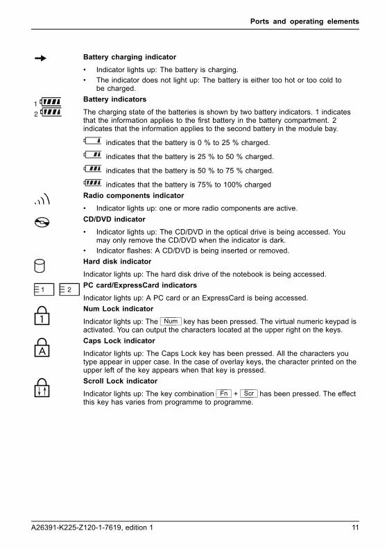
Battery charging indicatorBatterychargingindicatorIndicator
• Indicator lights up: The battery is charging.• The indicator does not light up: The battery is either too hot or too cold to
be charged.Battery indicatorsIndicatorIndicatorBattery
The charging state of the batteries is shown by two battery indicators. 1 indicatesthat the information applies to the first battery in the battery compartment. 2indicates that the information applies to the second battery in the module bay.
indicates that the battery is 0 % to 25 % charged. indicates that the battery is 25 % to 50 % charged. indicates that the battery is 50 % to 75 % charged. indicates that the battery is 75% to 100% charged
Radio components indicatorIndicatorIndicatorBluetoothIndicatorWirelessLAN
• Indicator lights up: one or more radio components are active.CD/DVD indicatorIndicatorCD/DVDindicator
• Indicator lights up: The CD/DVD in the optical drive is being accessed. Youmay only remove the CD/DVD when the indicator is dark.
• Indicator flashes: A CD/DVD is being inserted or removed.Hard disk indicatorHarddiskindicatorIndicator
Indicator lights up: The hard disk drive of the notebook is being accessed.PC card/ExpressCard indicatorsIndicatorIndicatorPCCardExpressCard
Indicator lights up: A PC card or an ExpressCard is being accessed.Num Lock indicatorIndicatorNumLock
Indicator lights up: The Num key has been pressed. The virtual numeric keypad isactivated. You can output the characters located at the upper right on the keys.Caps Lock indicatorIndicatorCapsLock
Indicator lights up: The Caps Lock key has been pressed. All the characters youtype appear in upper case. In the case of overlay keys, the character printed on theupper left of the key appears when that key is pressed.Scroll Lock indicatorIndicatorScrollLock
Indicator lights up: The key combination Fn + Scr has been pressed. The effectthis key has varies from programme to programme.
A26391-K225-Z120-1-7619, edition 1 11

Ports and operating elements
Key combinationsThe following description of key combinations refers to functions when usingMicrosoft Windows. Some of the following key combinations may not function inother operating systems and with some device drivers.
Key combinations are entered as follows:
► Press and hold the first key in the combination.► While holding the first key down, press the other key or keys in the combination.
The key combination Ctrl + Alt Gr or Ctrl + Alt can be used onexternal keyboards that do not not feature a Fn key.
Sleep modeFn+F1Sleepmode
This key combination is used to activate the suspend mode (S3).
Enable/disable loudspeakersFn+F3LoudspeakersLoudspeakers
This key combination switches your notebook’s loudspeakers off and on.
An audible signal will be produced when the loudspeakers are switched on.
Switch the touchpad on/off (if configured accordingly in BIOS)Fn+F4TouchpadLoudspeakers
This key combination enables and disables the touchpad.
Enlarge displayFn+F5DisplayFull-screenmode
This key combination enlarges the screen to the full-screen mode or switchesit back to the normal mode.
Decrease screen brightnessFn+F6Screenbrightness
This key combination decreases the brightness of the screen.
Increase screen brightnessFn+F7Screenbrightness
This key combination increases the brightness of the screen.
Decrease volumeFn+F8Volume
This key combination reduces the volume of the integrated loudspeakers.
12 A26391-K225-Z120-1-7619, edition 1

Ports and operating elements
Volume increaseFn+F9Volume
This key combination raises the volume of the integrated loudspeakers.
Toggle output screenFn+F10Toggleoutputscreen
If an external monitor is connected, the monitor on which the output is to bedisplayed can be selected with this key combination.
You can opt to use:
• just the notebook’s LCD screen• just the external monitor• both the LCD screen and the external monitor
+Ctrl CHalt current operationCtrl+C
This key combination can be used to halt an operation instantlywithout clearing the keyboard buffer.Switch between open applicationsWith this key combination you can switch between several openapplications.Alt+Tab
AltCtrlDel
SysRq+ +
Perform warm bootThis key combination triggers a reset and reboots the notebook. Firstpress and hold both the Ctrl and Alt key, then press the Delkey. This will cause the Task Manager to be displayed. The keycombination must be pressed a second time to reboot the system.Ctrl+Alt+DelWarmboot
Back tabThis key combination moves the cursor back to the previous tabularstop.Shift+TabBacktab
Key combinations using the Windows keys are detailed in the manualfor your operating system.
A26391-K225-Z120-1-7619, edition 1 13

Ports and operating elements
Easy Launch keysEasyLaunchkeys
Your notebook is equipped with four Easy Launch keys.
RE
Lock Workstation keyThis key allows you to lock your workstation. However, you can also configure this key as desired.
Mobility Center keyThis button starts the Mobility Center. However, you can also configure this key as desired.
E keyThe E key is a simple way of activating and deactivating power management functions (e.g.reduce screen brightness), see the "Professional Notebook" manual.
R key (recovery)Pressing the R key opens a dialog window in which you can backup or restore data.
Configuring Easy Launch keysThe Application Panel allows you to assign various functions to the Easy Launch keys.
Windows XP:You will find the Application Panel under Start - (Settings) - Control Panel - AdditionalControl Panel Options - Application Panel.
Windows Vista:You will find the Application Panel under Start symbol - Programs - Lifebook Application Panel.
14 A26391-K225-Z120-1-7619, edition 1

Ports and operating elements
Removing and installing the batteryNotesBattery
Only use batteries approved by Fujitsu Siemens Computers for your notebook.
Never use force when inserting or removing a battery.
Make sure that no foreign bodies get into the battery connections.
Removing the battery► Switch the notebook off and pull the power plug out of the mains socket.
Battery
► Close the LCD screen so that it locks into place.► Disconnect all cables connected to the notebook.► Turn your notebook over and place it on a stable, flat and clean surface. If necessary, lay
an anti-slip cloth on this surface to prevent the notebook from being scratched.
2
1
3
► Slide the battery release in the direction of the arrow (1) and hold it in place.The battery release is unlocked.
► Slide the hard disk carrier in the direction of the arrow (2) as far as it will go.A red field appears on the battery release.
► Slide the battery release in the direction of the arrow (1) again and hold it in place.► Tilt the battery on the red field of the battery release to one side and lift
it out of the battery compartment (3).
A26391-K225-Z120-1-7619, edition 1 15

Ports and operating elements
Inserting the battery
2
1
► Insert the battery in the battery compartment at an angle and push it in thedirection of the arrow (1) until it locks into place.Battery
► Push the battery release latch in direction of the arrow (2).
16 A26391-K225-Z120-1-7619, edition 1

Ports and operating elements
SIM cardA SIM Card (Subscriber Identity Module) is a chip card which is inserted in a mobiletelephone or notebook to enable access to a mobile radio network.
Follow the instructions supplied by the provider of the SIM card.
Inserting the SIM card► Switch the notebook off and pull the power plug out of the mains socket.► Close the LCD screen so that it locks into place.► Disconnect all cables connected to the notebook.► Turn your notebook over and place it on a stable, flat and clean surface. If necessary, lay
an anti-slip cloth on this surface to prevent the notebook from being scratched.► Remove the battery (see Section "Removing the battery", Page 15).
► Insert the SIM card into the slot so thatthe angled corner is at the front left whenpointing towards the slot and the chip isfacing downwards (1). Ensure that theSIM card snaps audibly into place.
► Reinstall the battery (see "Inserting the battery", Page 16).► Turn the notebook the right way up and place it on a flat surface.► Reconnect the cables that you disconnected previously.
A26391-K225-Z120-1-7619, edition 1 17

Ports and operating elements
Removing a SIM card► Switch the notebook off and pull the power plug out of the mains socket.► Close the LCD screen so that it locks into place.► Disconnect all cables connected to the notebook.► Turn your notebook over and place it on a stable, flat and clean surface. If necessary, lay
an anti-slip cloth on this surface to prevent the notebook from being scratched.► Remove the battery (see Section "Removing the battery", Page 15).
21
► Push the SIM card inwards slightly toeject it from the slot (1).
► Pull the SIM card out of the slot in thedirection of the arrow (2).
► Reinstall the battery (see "Inserting the battery", Page 16).► Turn the notebook the right way up and place it on a flat surface.► Reconnect the cables that you disconnected previously.
18 A26391-K225-Z120-1-7619, edition 1

Ports and operating elements
Radio components: UMTS (optional)/wirelessLAN/BluetoothWirelessLANBluetoothUMTS
The installation of a wireless LAN, Bluetooth or UMTS module not approved by FujitsuSiemens Computers GmbH voids the permits (CE!, FCC) issued for this device.
Fujitsu Siemens Computers GmbH has printed the correct permit number forall factory-installed radio components on the rating plate.
The modules for radio components are switched off during shipping.
Switching the radio components on and off► Slide the ON/OFF button into the "ON"
position to activate the radio components.WirelessLANWirelessLANBluetoothBluetooth
or► Slide the ON/OFF button to the
"OFF" position to deactivate theradio components.
If you switch off the radio components, the Bluetooth and UMTS modules are poweredoff and the wireless LAN transmission unit (antenna) is switched off.
The Wireless Selector enables you to switch the various radio components on and off.
You can also deactivate the radio components individually in the BIOS setup.
Pay attention to the additional safety notes for devices with radiocomponents provided in the "Safety" manual.
Details on using the wireless LAN are contained in the online help for yourwireless LAN software and in the "Wireless LAN" manual. (The "Wireless LAN"manual can be found on the "Drivers & Utilities" CD/DVD.)
You can find more information on how to use Bluetooth on the CD youreceived with your Bluetooth software.
You can obtain more information on UMTS from your service provider.
A26391-K225-Z120-1-7619, edition 1 19

Removing and installing components during servicing
Removing and installing componentsduring servicing
Only qualified technicians should repair your notebook. Unauthorisedopening or incorrect repair may greatly endanger the user (electric shock,fire risk) and will invalidate your warranty.Components
Servicing
You may remove and install the components described in this chapter yourselfafter consulting the Hotline/Help Desk.
If you remove and install components without consulting the Hotline/HelpDesk, then the warranty of your notebook will be voided.
Notes on installing and removing boardsand components• Switch the notebook off and pull the power plug out of the mains socket.• Remove the battery.• Take care when you use the locking mechanisms on the battery and any other component.• Never use sharp objects such as screwdrivers, scissors or knives as leverage to remove covers.
NotesBoardESD
Boards with electrostatic sensitive devices (ESD) are marked with the labelshown.
When handling boards fitted with ESDs, you must always observe the followingpoints:
• You must always discharge static build up (e.g. by touching a groundedobject) before working.
• The equipment and tools you use must be free of static charges.• Remove the power plug from the mains supply before inserting or removing
boards containing ESDs.• Always hold boards with ESDs by their edges.• Never touch pins or conductors on boards fitted with ESDs.
20 A26391-K225-Z120-1-7619, edition 1

Removing and installing components during servicing
Hard diskThe hard disk is the most important storage medium of your notebook. You can work considerablyfaster and more efficiently if you copy applications and files from CDs to your hard disk.
When the hard disk is accessed, the hard disk indicator lights up in the statusindicator panel, see "Status indicator panel", Page 10.
Removing the hard disk► Switch off your notebook and disconnect the power plug from the mains.
Harddisk
► Close the LCD screen so that it locks into place.► Disconnect all cables connected to the notebook.► Turn your notebook over and place it on a stable, flat and clean surface. If necessary, lay
a non-slip cloth on this surface to prevent the notebook from being scratched.► Remove the battery (see "Removing the battery", Page 15).
1
2
► Remove the screw (1).► Lift the cover off the notebook (2).
A26391-K225-Z120-1-7619, edition 1 21

Removing and installing components during servicing
1
a
2
► Grasp the hard disk by the pulling aid (a) and pull in the direction indicated by the arrow (1).The hard disk separates from the disk connector.
► Lift the hard disk out of the hard disk compartment (2).
1
1
1
1
► Loosen the screws (1) of the hard disk carrier.► Remove the hard disk from the hard disk carrier.
22 A26391-K225-Z120-1-7619, edition 1

Removing and installing components during servicing
Installing the hard disk
1
1
1
1
► Insert the hard disk into the hard disk carrier.► Fasten the hard disk carrier with the screws (1).
3
b
a
1
2
► Insert the hard disk at an angle into the hard disk compartment (1). Ensure that the eyelet(a) on the hard disk holder is inserted correctly into the existing opening.
► Place the hard disk in the hard disk compartment (2).► Pull the hard disk by the pulling aid (b) in the direction indicated by the arrow (3) until
the hard disk can be felt to latch into the hard disk connector.
If the pulling aid (b) sticks out too far from the hard disk, it will not bepossible to fasten the hard disk cover correctly.
► Lay the pulling aid (b) down flat on the hard disk.
A26391-K225-Z120-1-7619, edition 1 23

Removing and installing components during servicing
2
1
► Place the cover on its mounting location (1), ensuring it snaps into place.► Fasten the cover with the screw (2).► Install the battery again (see "Inserting the battery", Page 16).► Turn the notebook the right way up and place it on a flat surface.► Reconnect the cables that you disconnected previously.
24 A26391-K225-Z120-1-7619, edition 1

Removing and installing components during servicing
Removing and installing memory modulesMainmemoryMemoryexpansionMemoryupgradeSystemexpansion
The notebook will not start without memory modules, as no fixed RAM is installed.
Your notebook supports dual-channel DDR2 technology.
The dual-channel DDR2 technology can only be used with two identicalmemory modules. When two different memory modules are installed, only"single-channel" performance is supported.
If you are asked by the Hotline/Help Desk to remove and install the memorymodules yourself, proceed as follows:
Pay attention to the relevant safety notes provided in the "Important notes" chapter.
The notebook must be switched off when installing/removing the memorymodules, it must not be in Suspend mode.
Only use approved memory expansion modules in your notebook(see Section "Technical data", Page 28).
Never use force when installing or removing memory modules.
Make sure that foreign objects do not fall into the memory expansion compartment.
Individual components (e.g. the processor heat sink) can become very hotduring operation. Therefore, we recommend that you wait one hour afterswitching off the notebook before removing or installing the memory modules.Otherwise, there is a risk of suffering burns!
As some non-ESD safe components are exposed, please observe the section "Noteson installing and removing boards and components", Page 20.
► Switch your notebook off and unplug the mains adapter from the mains outlet.► Close the LCD screen so that it locks into place.► Disconnect all cables connected to the notebook.► Turn your notebook over and place it on a stable, flat and clean surface. If necessary, lay
an anti-slip cloth on this surface to prevent the notebook from being scratched.► Remove the battery (see "Removing the battery", Page 15).
A26391-K225-Z120-1-7619, edition 1 25

Removing and installing components during servicing
Removing the cover
21
► Remove the screws (1).► Pull the cover off the notebook (2).
Removing memory modules
32
1
1
► Carefully push the two mountingclips outwards (1).MemoryexpansionMemorymodule
The memory module snaps upwards (2).► Pull the memory module out of its slot
in the direction of the arrow (3).
Installing a memory module
2
a
1
► Insert the memory module with the contactsand the recess (a) facing the slot (1).MemoryexpansionMemorymodule
► Carefully push the memory moduledownwards until you feel it clickinto place (2).
26 A26391-K225-Z120-1-7619, edition 1

Removing and installing components during servicing
Attaching the cover
12
► Place the cover in the correctmounting position (1).
► Secure the cover with the screws (2).
► Reinstall the battery (see "Inserting the battery", Page 16).► Turn the notebook the right way up and place it on a flat surface.► Reconnect the cables that you disconnected previously.
A26391-K225-Z120-1-7619, edition 1 27
Technical data
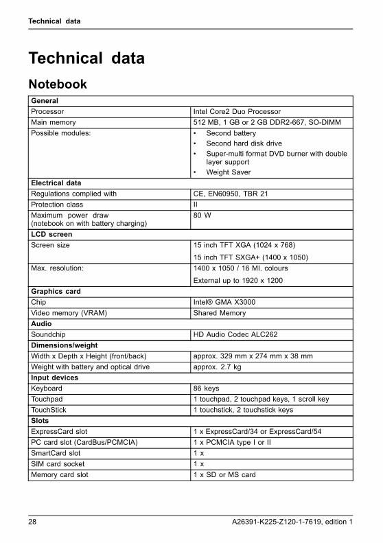
Technical dataNotebookTechnicaldata
GeneralProcessor Intel Core2 Duo ProcessorMain memory 512 MB, 1 GB or 2 GB DDR2-667, SO-DIMMPossible modules: • Second battery
• Second hard disk drive• Super-multi format DVD burner with double
layer support• Weight Saver
Electrical dataRegulations complied with CE, EN60950, TBR 21Protection class IIMaximum power draw(notebook on with battery charging)
80 W
LCD screenScreen size 15 inch TFT XGA (1024 x 768)
15 inch TFT SXGA+ (1400 x 1050)Max. resolution: 1400 x 1050 / 16 MI. colours
External up to 1920 x 1200Graphics cardChip Intel® GMA X3000Video memory (VRAM) Shared MemoryAudioSoundchip HD Audio Codec ALC262Dimensions/weightWidth x Depth x Height (front/back) approx. 329 mm x 274 mm x 38 mmWeight with battery and optical drive approx. 2.7 kgInput devicesKeyboard 86 keysTouchpad 1 touchpad, 2 touchpad keys, 1 scroll keyTouchStick 1 touchstick, 2 touchstick keysSlotsExpressCard slot 1 x ExpressCard/34 or ExpressCard/54PC card slot (CardBus/PCMCIA) 1 x PCMCIA type I or IISmartCard slot 1 xSIM card socket 1 xMemory card slot 1 x SD or MS card
28 A26391-K225-Z120-1-7619, edition 1
Technical data
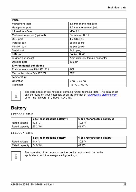
PortsMicrophone port 3.5 mm mono mini-jackHeadphone port 3.5 mm stereo mini jackInfrared interface IrDA 1.1Modem connection (optional) Connector, RJ11USB port 4 x USB 2.0Parallel port 25-pin socketMonitor port 15-pin socketSerial port 9-pin plugLAN port Socket, RJ45S-Video out socket 7-pin mini DIN female connectorDocking port 100-pinEnvironmental conditionsEnvironment class DIN IEC 721 3K2Mechanism class DIN IEC 721 7M2Temperature:Operation 5 °C ... 35 °CTransport -15 °C ... 60 °C
The data sheet of this notebook contains further technical data. The data sheetcan be found on your notebook or on the Internet at "www.fujitsu-siemens.com"or on the "Drivers & Utilities" CD/DVD.
BatteryTechnicaldata
LIFEBOOK E8310
6-cell rechargeable battery 1 6-cell rechargeable battery 2Rated voltage 10.8 V 10.8 VRated capacity 56.2 Wh 41 Wh
LIFEBOOK E8410
8-cell rechargeable battery 6-cell rechargeable batteryRated voltage 14.4 V 10.8 VRated capacity 74.9 Wh 41 Wh
The operating time depends on the device equipment, the activeapplications and the energy saving settings.
A26391-K225-Z120-1-7619, edition 1 29

Technical data
Mains adapterTechnicaldata
Primary
Rated voltage 100 V or 240 V (automatic)Rated frequency 50 Hz to 60 Hz (automatic)
Secondary
Rated voltage 19 V
Additional mains adapters and an power cables are can be ordered at any time.
30 A26391-K225-Z120-1-7619, edition 1

Index
IndexAAlt+Tab 13
BBack tab 13Battery 7
important notes 15indicator 11inserting 16removing 15
Battery charging indicator 11Battery release 7Bluetooth 19
Indicator 11Switching off 19Switching on 19
Board 20
CCaps Lock
indicator 11CD/DVD indicator 11Components
installing / removing 20Ctrl+Alt+Del 13Ctrl+C 13
DDC IN jack 5Display
enlarge 12
EEasy Launch keys 4, 14ESD 20ExpressCard
indicator 11ExpressCard slot 5
FFn + F1 12Fn + F10 13Fn + F3 12Fn + F4 12Fn + F5 12Fn + F6 12Fn + F7 12Fn + F8 12
Fn + F9 13Front 4–5Full-screen mode 12
HHard disk 7
removing 21Hard disk indicator 11
IIndicator
Battery charging indicator 11Bluetooth 11Caps Lock 11CD/DVD 11ExpressCard 11First battery 11Hard disk indicator 11Num Lock 11PC-Card 11Power indicator 10Power-on indicator 10Radio components 11Scroll Lock 11Second battery 11Wireless LAN 11
KKensington Lock 6Keyboard 4
LLAN port 6LCD screen 4Left side 5Loudspeaker 4Loudspeakers
disable 12enable 12
MMain memory 25Memory expansion 25
installing 26removing 26
Memory module 7installing 26removing 26
A26391-K225-Z120-1-7619, edition 1 31

Index
Memory upgrade 25Modem port 6Module 6Monitor port 5
NNotes
battery 15boards 20
Num Lockindicator 11
OOn/Off switch 4
PParallel port 6PC Card
indicator 11PC card slot 5Port for port replicator 7Ports 4Power indicator 10Power-on indicator 10
RRear 6Right side 6
SS-Video out socket 5Screen brightness
decrease 12increase 12
Scroll Lockindicator 11
Serial port 5Servicing 20Shift+Tab 13Sleep mode
activating 12
SmartCard reader 5Status indicator panel 4, 10System expansion
memory expansion 25
TTechnical data
Battery 29Mains adapter 30notebook 28
Toggle output screen 13Touchpad 4
disable 12Touchpad keys 4TouchStick 4TouchStick keys 4
UUMTS 19Underside 7USB port 5USB ports 6
VView
front 4–5Left side 5rear 6Right side 6
Volumedecrease 12increase 13
WWarm boot 13Wireless LAN 19
Indicator 11Switching off 19Switching on 19
32 A26391-K225-Z120-1-7619, edition 1