Embed Size (px)
Citation preview

GP300_owners.book Page 1 Thursday, August 7, 1997 9:49 AM
GP300Portable RadiosOperating Instructions

GP300_owners.book Page 2 Thursday, August 7, 1997 9:49 AM
2-YEAR LIMITED WARRANTYFOR RADIOS
We thank you for purchasing our Motorola radios. Theseradios are manufactured according to the highest qualitystandards set and are backed by Motorola’s two (2) yearwarranty. The rechargeable Motorola supplied batteries havea one (1) year warranty. Kindly approach your dealer for moreinformation.
Motorola warrants its radios and batteries against defects inmaterial and workmanship under normal use and service forthe period stated above.
Motorola recommends that you use Motorola suppliedaccessories and batteries in connection with the radio. Wewould also advise you against attempting any modificationsor repairs or any other form of unauthorised service to yourradio.Should you have any queries, please contact:
Singapore -Telephone/Fax: (65)2812053/2874181Beijing -Telephone/Fax: (86-10)68438231/4610277
Please see the next page for more information.
Fill in the details of your radio below for your own reference:Model Name/No.:Serial Number:Date of Purchase:Dealer Name:Address:Telephone:

GP300_owners.book Page 3 Thursday, August 7, 1997 9:49 AM
LIMITED WARRANTY MOTOROLA RADIO PRODUCTS
Limited WarrantyThis express limited warranty covers the Product manufactured by MOTOROLA RadioProducts Group and applies to any warranty already mentioned. MOTOROLA assumesno obligations or liability for additions or modifications to this warranty unless specificallymade in writing and signed by an authorised officer of MOTOROLA.
MOTOROLA cannot be responsible in any way for any ancillary equipment not furnishedby MOTOROLA which is attached to or used in connection with the Product, or for oper-ation of the Product with any ancillary equipment, and all such equipment is expressly ex-cluded from this warranty. Because each system which may use the Product is unique,MOTOROLA disclaims liability for range, coverage, or operation of the system as a wholeunder this warranty.
This warranty sets forth the full extent of MOTOROLA’S responsibilities regarding theProduct. Repair, replacement or refund of the purchase price, at MOTOROLA’S option,is the sole and exclusive remedy of purchaser/user of the Product. THIS WARRANTY ISGIVEN IN LIEU OF ALL OTHER EXPRESS WARRANTIES. IMPLIED WARRANTIES,INCLUDING WITHOUT LIMITATION, IMPLIED WARRANTIES OF MERCHANTABILITYAND FITNESS FOR A PARTICULAR PURPOSE, ARE HEREBY EXCLUDED. IN NOEVENT SHALL MOTOROLA BE LIABLE FOR DAMAGES IN EXCESS OF THE PUR-CHASE PRICE OF THE PRODUCT, FOR ANY LOSS OF USE, LOSS OF TIME, INCON-VENIENCE, COMMERCIAL LOSS, LOST PROFITS OR SAVINGS OR OTHERINCIDENTAL, SPECIAL OR CONSEQUENTIAL DAMAGES ARISING OUT OF THEUSE OR INABILITY TO USE SUCH PRODUCT, TO THE FULL EXTENT SUCH MAY BEDISCLAIMED BY LAW.
Notwithstanding anything contained herein, MOTOROLA shall not be liable for any of thefollowing situations:
A) Defects or damage resulting from use of the Product in other than its normal and customary manner.
B) Defects or damage from misuse, accident, water, liquid or neglect.
C) Defects or damage from improper or unauthorized testing, operation, maintenance, service, repair, installation, alteration, modification, or adjustment.
D) Product which has had the serial number removed or made illegible.
E) A Product which, due to illegal or unauthorized alteration of the software/firmware in the Product, does not function in accordance with Motorola’s published specifications or the FCC type acceptance labeling in effect for the Product at the time the Product was initially distributed from Motorola.
F) Scratches or other cosmetic damage to Product surfaces that does not affect the operation of the Product.
MOTOROLA shall have no liability whatsoever with respect to any claim of patent in-fringement which is based upon the combination of the Product or parts furnished here-under with software, apparatus or devices not furnished by MOTOROLA, nor willMOTOROLA have any liability whatsoever for the use of ancillary equipment or softwarenot furnished by MOTOROLA which is attached to or used in connection with the Product.
HOW TO GET WARRANTY SERVICE: Provide proof of purchase and deliver or send theProduct item, transportation and insurance prepaid, to an authorized warranty service lo-cation. Warranty service will be provided by Motorola through one of its authorized war-ranty service locations. If you contact the company that sold you the Product, it canfacilitate your obtaining warranty service. You can also call Motorola for assistance: 65-2812053 (Singapore) or 86-10-68438231 (Beijing).

GP300_owners.book Page 4 Thursday, August 7, 1997 9:49 AM
Motorola PenangBayan Lepas Free Industrial ZonePhase III11900 Penang, Malaysia
6804370J52-B

GP300_owners.book Page 5 Thursday, August 7, 1997 9:49 AM
WARNINGCertain combinations of chemical environments can adversely affect thermoplastic resins, the material the housing of the radio is made from. For this reason, lubricants, cleaning agents, solvents or any other material which may come in contact with the housing of the radio should be carefully evaluated for compatibility. We rec-ommend a mild dishwashing soap for cleaning the exterior of the product.
Recycling or Disposal of Batteries
This portable radio is powered by a nickel-cadmium (Ni-Cad) recharge-able battery. At the end of its useful life, the battery can be recycled. However, recycling facilities may not be available in all areas. Under various state or local laws, the battery must be recycled or disposed of properly and cannot be disposed of in landfills or incinerators.
In addition, U.S. Environmental Protection Agency (EPA) regulations classify used Ni-Cad batteries as hazardous waste, unless certain exemptions apply.
Motorola fully endorses and encourages the recycling of Ni-Cad batter-ies. If you are located in the United States, you can ship post paid your used Ni-Cad batteries to INMETCO, an EPA approved recycling facility, at this address:
INMETCOP.O. Box 720245 Portersville RoadEllwood City, PA 16117Telephone: (412) 758-5515Fax: (412) 758-9311
Consideration should be given to the methods of collecting, labeling, and shipping used Ni-Cad batteries. Your federal, state or locate EPA should be consulted for specific legal requirements and for recycling options in your area.
Motorola, as a responsible corporate citizen, has always been con-cerned with the protection of the environment. Please feel free to call the phone number 1-800-422-4210 for further information.

GP300_owners.book Page 1 Thursday, August 7, 1997 9:49 AM
Quick Reference Card
Antenna Installation
Rotate the antenna clockwise until hand tightinto the antenna connector on the top of theradio.
Battery Installation or Replacement
1. Turn off the radio and hold it with the back ofthe radio facing up.
2. Disengage the battery latch on the bottom ofthe radio by pushing and holding the latchtowards the front of the radio. (See Figure 1.)
3. While holding the battery latch, slide the bat-tery down from the top of the radio about 1/2of an inch. Once the battery is free from thecontrol rails, lift it directly upward to remove.
4. To install a fresh battery, align the belt clipend of the battery with the control rails on theradio. (See Figure 2.) Slide the battery
toward the top of the radio until it is fullyengaged by the battery latch.
To Receive
1. Turn the radio on and rotate the CHANNELSELECTOR to the desired channel position.(See Figure 3.)
2. Listen for a transmission or hold the MONI-TOR BUTTON to hear back-ground noise.Adjust the VOLUME CONTROL to a comfort-able listening level. (See Figure 4.)
3. To monitor a channel (disable PL/DPL) press theside mounted CONTROL BUTTON. The LEDglows yellow for 4 seconds to confirm that thecoded squelch is disabled. To reverse the moni-tor status, press this button again.
Figure 1.
BatteryLatch
Figure 2.
AccessoryConnector
ChannelSelector
LEDIndicator
On/Off/VolumeControl
Figure 3.
Monitor Button(Volume Set) or
(Scan Nuisance Delete)
Control Button
Push-To-TalkButton (PTT)
Figure 4.

GP300_owners.book Page 2 Thursday, August 7, 1997 9:49 AM
To Transmit
1. Turn the radio on and rotate the CHANNELSELECTOR to the desired channel position.
2. Press the MONITOR BUTTON to listen foractivity on your channel.
3. While holding the radio two to three inchesfrom your mouth, press the PTT button on theside of the radio and speak. The LED glowsred to indicate transmit status. When finishedtransmitting, release the PTT button toreceive.
NOTEWhen the PTT button is depressed,the LED flashes red if there is a lowbattery condition. In addition, a doublealert tone is sounded when the PTTbutton is released.
Time-Out-Timer (T.O.T)The T.O.T feature ends a transmission which isover 60 seconds in length. After time out, a con-tinuous alert tone sounds until the PTT button isreleased.
Voice Activated Transmission(VOX)
To activate the VOX feature, insert a headset inthe accessory connector on a channel pro-grammed for VOX. You can gain manual controlof the radio by pressing the PTT button at anytime. In order to restart the VOX feature, theradio must be turned off/on or the channel mustbe changed.
Optional Feature Enhancements(Not Available on 2 ChannelModels)
Channel Scan
To initiate the scan feature, rotate the CHAN-NEL SELECTOR to the location with the scanlist programmed to it. The radio will stop on anyactive channel and you will be able to hear theconversation. The radio scans for PL/DPLunless the monitor feature is active and CSQscan will operate. To locate the last active scanchannel, rotate the CHANNEL SELECTOR andthe radio beeps when that channel is reached.To temporarily eliminate a channel from thescan list, press the side NUISANCE DELETEBUTTON while the nuisance channel is active.
PTT ID (Encode)Every time the PTT button is pressed, the radioautomatically transmits a unit identification (ID)number. While holding the PTT button, a tonemay be heard while the unit ID number is beingsent out.
Call Alert (Decode)When a Call Alert is received, the monitor LEDflashes yellow and a series of 4 alert tonessound. A Call Alert “leaves a message” for themobile operator. The monitor LED continues toflash yellow, and the alert tones repeat every 10seconds until the PTT or any other button ispressed. The radio then returns to normal oper-ation.
Voice Selective Call (Decode)When a Voice Selective Call is received, a one-time 2 beep alert tone sounds, the monitor LEDflashes yellow and the radio emits a voice mes-sage. After the transmission is completed, theradio returns to normal operation.
GP300 Portable Radios
GP300_owners.book Page 1 Thursday, August 7, 1997 9:49 AM
ContentsQuick Reference Card ..........................................front cover flapWarning............................................................. inside front coverIntroduction .................................................................................2Inspection....................................................................................3Controls, Switches, Indicators, and Connectors .........................4Alert Tone Indicators...................................................................6Scan and Signalling Alert Tones.................................................8Multifunctional LED Indicators ....................................................9Dealer Programmable Functions ..............................................10
HOW TO OPERATE YOUR GP300 RADIOGetting Started..........................................................................11Operation ..................................................................................13Operation with Standard Features ............................................15Optional Feature Enhancements ..............................................18Optional Signalling Enhancements ...........................................21DTMF Telephone Interconnect .................................................23
BATTERIES, CHARGERS AND ACCESSORIESBattery Information....................................................................25Battery Chargers Operating Instructions...................................27Accessories...............................................................................30Belt Clip Installation Instructions ...............................................32
SAFETY AND SERVICEFor Use in Hazardous Atmospheres.........................................33Troubleshooting ........................................................................34Service ......................................................................................35General Radio Care ..................................................................36Safety Information.....................................................................37Computer Software Copyrights.................................................38Licensing Information................................................................39
, Motorola, GP300, Private-Line, Digital Private-Line, Touch-Code, RapidCall, and Quik-Call II are trademarks of Motorola Inc.
©1997 by Motorola Inc.Motorola Malaysia Sdn. Bhd. (Company No. 12631DE),Bayan Lepas Free Industrial Zone, Phase III11900 Penang, MalaysiaPrinted in Malaysia. All Rights Reserved.
1

Introduction GP300 Portable Radios
GP300_owners.book Page 2 Thursday, August 7, 1997 9:49 AM
IntroductionWelcome To The Motorola GP300 Radio
The Motorola GP300 Portable Radio is a sophisticated state-of-the-art unit. It incorporates the latest technology available in two-way radio communications.
The use of microcomputer technology makes changing radio characteristics such as operating frequencies and squelch codes both economical and fast. Any computer equipped dealer can easily reprogram your radio's operat-ing characteristics, or your radio can be "cloned" from a radio already programmed to your desired frequencies and codes.
The GP300 radio meets tough environmental demands while providing cost effective and reliable communications. It meets the U.S. Government Military Standards 810C, D and E for low pressure, high temperature, low temperature, temperature shock, solar radiation, rain, humidity, salt fog, dust, vibration, and shock. The GP300 radio also meets the Electronic Industry Association RS316B electrical and mechanical specifications. The Motorola Accelerated Life Test (ALT) assures that possible failures brought on by field stress and abuse are identified and designed out of your radio before it reaches your hands.
All of these features provide for better, yet more cost effec-tive communications for you.
2

GP300 Portable Radios Inspection
GP300_owners.book Page 3 Thursday, August 7, 1997 9:49 AM
InspectionWhen you receive your packaged GP300 Radio, inspect the shipping carton for any signs of damage. Next, remove and check the contents of the packing case to be sure that all items ordered have been included. Contents of the packing case may be different from the standard items listed below if optional accessories were ordered.
Packaged Model Contents• GP300 Radio
• Heliflex Antenna (VHF Models) or Flexible Whip Antenna (UHF Models)
• Rapid Charge High Capacity Nickel-Cadmium Battery
• Radio Belt Clip
• Operating Instructions Manual
• Compact 10 Hour Charger and Transformer
Inspect the equipment thoroughly. If any part of the equip-ment has been damaged in transit, report the extent of the damage to the transportation company immediately.
GP300Radio
Battery
RadioBelt Clip
Compact10 Hr Charger
Antenna
ChargerTransformer
3

Controls, Switches, Indicators and Connectors GP300 Portable Radios
GP300_owners.book Page 4 Thursday, August 7, 1997 9:49 AM
Controls, Switches, Indicatorsand Connectors
On/Off/Volume Control
Turns the radio on and off and adjusts the volume level.
Rotary Channel Selector Switch
Selects the operating channel or initiates scan operation (on applica-ble models).
LED Indicator
A tri-colored light-emitting diode (LED) indicates the radio operating status.
Accessory Connector
Provides accessibility for connec-tion to remote accessories such as a remote speaker microphone.
NOTEThe Accessory Connector Cover protects the Accessory Connector. This cover should remain in place whenever the radio is not being used with an accessory.
On/OffVolumeControl
Rotary ChannelSelector Switch
LED IndicatorAccessoryConnectorCover
Top View
4

GP300 Portable Radios Controls, Switches, Indicators and Connectors
GP300_owners.book Page 5 Thursday, August 7, 1997 9:49 AM
Push-To-Talk (PTT) Button
When depressed and held, engages the transmitter and puts radio in the transmit mode. When released, the radio operates in the receive mode.
Monitor Button (PL/DPL Disable)
Selects the mode of operation, carrier squelch (CSQ) or Private-Line/Digital Private-Line (PL/DPL squelch).
Control Button
When depressed, this monitors the channel for any activity. Nei-ther CSQ nor PL/DPL squelch is active when monitoring. The radio has the ability to monitor all activity on the radio channel, whenever this button is pressed. This control button can also be programmed for nuisance chan-nel delete on radio models with the channel scan feature.
Antenna
Heliflex (VHF models) or a Flexible Whip (UHF models) with threaded base.
MonitorButton
PTT Button
ControlButton
Flexible Whip
Heliflex
5

Alert Tone Indicators GP300 Portable Radios
GP300_owners.book Page 6 Thursday, August 7, 1997 9:49 AM
Alert Tone IndicatorsPower-Up
Each time the radio is turned on, a microcomputer and syn-thesizer self-test occurs. A high pitched alert tone is gener-ated for approximately 1/8 second to indicate that the microcomputer and synthesizer are functioning properly. A second low pitched tone will then be generated if the start-up test is not successful.
Transmit on Blank or Receive-Only Channels
Pressing the PTT button while tuned to a blank or “receive-only” channel will cause an alert tone. The tone will continue as long as the PTT button is depressed. The radio transmit-ter is not enabled.
Transmit Inhibit on Busy Channel with Busy Channel Lockout
Pressing the PTT button during a "busy channel" condition (other than your PL/DPL group) generates a continuous busy tone that lasts as long as the button is depressed.
Time-Out-Timer
The Time-Out-Timer (T.O.T.) limits the amount of transmis-sion time to a preset length. At the end of this time an alert tone indicates that your transmission has been cut off. The alert con-tinues as long as the PTT button is depressed.
6

GP300 Portable Radios Alert Tone Indicators
GP300_owners.book Page 7 Thursday, August 7, 1997 9:49 AM
Low Battery Alert
If the battery is low on your radio, an audible alert tone alerts you during transmit or receive mode. During transmit, on the release of the PTT button the radio emits 2 medium pitched chirp tones. During receive/standby mode, the radio emits 2 medium pitched chirp tones. These tones emit approximately every 20 minutes during transmit or receive mode until the battery is completely drained of power.
7

Scan and Signalling Alert Tones GP300 Portable Radios
GP300_owners.book Page 8 Thursday, August 7, 1997 9:49 AM
Scan and Signalling Alert TonesTransmit on Radios with PTT-ID
When the PTT button is depressed a side tone is heard as the unit I.D. is being transmitted. When the tone ends, start your voice message in the standard manner.
Selective CallA 2 beep alert tone is generated whenever a Selective Call is received, the radio unsquelches and the callers message is heard.
Call AlertA 4 beep alert tone is generated whenever a Call Alert (page) is received. The alert tone repeats until the PTT or monitor button is pressed.
Scan ActivateA 1 beep alert tone is heard whenever scan is initiated by selecting a preprogrammed rotary scan channel location.
Priority Alert ToneA 1 beep alert tone is heard if the radio is scanning and a conversation is initiated on the priority scan channel.
Scan Talkback Tone A medium pitched 1 beep alert tone is sounded when you rotate the channel selector knob out of the scan position after the radio has locked on a channel and reaches the last active channel within the channel scan list.
8

GP300 Portable Radios Multifunction LED Indicators
GP300_owners.book Page 9 Thursday, August 7, 1997 9:49 AM
Multifunction LED IndicatorsTransmit Mode (PTT Button Depressed)
• Continuous Red Light - Normal Transmission
• Flashing Red Light - Low Battery
Receive Mode (PTT Button Not Depressed)• Flashing Red Light - Channel Busy, indicates the pres-
ence of activity on the operating channel
• Continuous Yellow Light (5 seconds) - Channel Monitor Active (PL/DPL Disable)
• Flashing Yellow Light - Selective Call or Call Alert Present
• Flashing Green Light - Channel Scan Feature Active
9

Dealer Programmable Functions GP300 Portable Radios
GP300_owners.book Page 10 Thursday, August 7, 1997 9:49 AM
Dealer Programmable FunctionsPer Radio Functions Default
All Alert Tones EnabledAll LED Indicators EnabledLow Battery Alert EnabledTime-Out-Timer Enabled to 60 secondsChannel Busy Light DisabledBattery Saver DisabledVOX Operation DisabledControl Button 1 Volume SetControl Button 2 Monitor (PL Disable)
Per Channel Functions Default
Rx Frequency TestTx Frequency TestPL/DPL Decode TestPL/DPL Encode TestRx Only Channel DisabledBusy Channel Lockout Disabled
Channel Scan Functions (Not Available on 2 Channel Models)
Channel Scan List TestTalkBack Channel Scan EnabledScan Activate Tone EnabledPriority Alert Tone DisabledTalk Back Channel Tone Enabled
Signalling Functions (Not Available on 2 Channel Models)
DTMF Signalling DisabledQuik Call Signalling DisabledMDC-1200 Signalling Test
10

GP300 Portable Radios Getting Started
GP300_owners.book Page 11 Thursday, August 7, 1997 9:49 AM
Getting StartedAntenna Installation
Fasten the antenna to the radio by placing the threaded end of the antenna into the large threaded antenna bushing on top of the radio. Rotate the antenna clockwise until hand tight.
11

Getting Started GP300 Portable Radios
GP300_owners.book Page 12 Thursday, August 7, 1997 9:49 AM
Battery Installation or Replacement
1. Turn off the radio and hold it in one hand with the back of the radio facing up.
2. Disengage the battery latch on the bottom of the radio by pushing and holding the latch towards the front of the radio.
3. With the battery latch disengaged, slide the battery down from the top of the radio about 1/2 of an inch. Once the battery is free from the control rails, lift it directly upward to remove the battery from the radio housing.
4. To install the new or freshly charged battery, align the top of the battery (belt clip end) with the stamped hous-ing figure showing the correct battery positioning. Slide the battery toward the top of the radio until it is fully engaged by the battery latch.
NOTENickel-Cadmium batteries should be fully charged before their first use.
BatteryLatch
12

GP300 Portable Radios Operation
GP300_owners.book Page 13 Thursday, August 7, 1997 9:49 AM
OperationTo Power-Up
Rotate the volume control 1/2 turn clockwise to turn on the radio. A power-up alert tone is generated for approxi-mately 1/8 second to indicate that the radio has passed a self-test of the microcomputer.
NOTEIf the short power-up alert tone is not gener-ated, or if a second low alert tone is generated (indicating corrupted radio programming), turn the radio off, check the battery (charge or replace if necessary), and turn the radio back on again. If the power-up alert tone is still not generated, a fault exists in the radio. Contact your local Motorola dealer.
To Receive
1. Set the channel selector to the desired channel position.
2. Listen for a transmission and adjust the volume control to a comfortable listening level. If no transmission is heard, depress and hold the volume set button to unsquelch the radio (on applicable models), and adjust the background noise to a comfortable listening level.
3. The radio is now set to receive all calls on the selected frequency.
4. If you wish to monitor a channel (disable PL/DPL) press the side mounted monitor button. The LED glows yel-low for 4 seconds, to confirm that the coded squelch is disabled. Any time the PTT button is pressed when the GP300 is in the PL/DPL disable mode, the LED tempo-rarily glows yellow to remind you that this state is active. The radio remains in the monitor state until the monitor button is pressed again, to reverse the state.
13

Operation GP300 Portable Radios
GP300_owners.book Page 14 Thursday, August 7, 1997 9:49 AM
NOTEAll GP300 radio models have an internal squelch setting which is adjusted at the factory. The squelch level setting is not a user-operated control; however, it may be reprogrammed through the Radio Service Software available at your local Motorola dealer.
To Transmit1. Set the channel selector to the desired channel position.
2. Do not interrupt another user. Listen for activity on your channel. If the channel on which you are transmitting is programmed to receive PL/DPL, momentarily depress the monitor button to listen for channel activity. The channel must be clear before transmitting.
3. While holding the radio in a vertical position with the speaker-microphone grille two to three inches from your mouth, press the PTT button on the side of the radio and speak slowly and clearly into the grille area. When finished transmitting, release the PTT button to receive. When the PTT button is depressed the LED glows red and remains on for the entire length of the transmission, and turns off when the PTT button is released.
NOTEWhen the PTT button is depressed (and as long as the PTT button remains depressed), the bat-tery voltage is automatically monitored and if the voltage is low, the LED flashes red to alert you of the low battery condition. In addition, a double alert tone is sounded when the PTT is released.
NOTEThe power to the radio should be turned OFF when an audio accessory with a microphone is to be connected to the radio. Such items include Headsets w/mics, Speaker-Micro-phones and Surveillance Microphones. Follow-ing this procedure ensures proper operation of the PTT button and other controls.
14

GP300 Portable Radios Operation with Standard Features
GP300_owners.book Page 15 Thursday, August 7, 1997 9:49 AM
Operation with Standard FeaturesTo fit your particular needs, a number of features are avail-able to enhance the operation of your GP300 radio. These capability features are described for you in this section.
Time-Out-Timer
The Time-Out-Timer (T.O.T.) feature alerts you if the trans-mitter is keyed for a long period. This feature prevents chan-nel tie-up and excess battery drain in case of an inadvertent keying of the transmitter. The radio operates normally in the receive mode with the T.O.T. feature. However, in the trans-mit mode, a single transmission (uninterrupted depression of the PTT) "times-out" after 60 seconds and the radio reverts back to the receive mode, even with the PTT button remaining depressed. After the 60 second time out, a con-tinuous alert tone is generated in the receive mode until the PTT button is released.
Volume Set
Pressing one of the side but-tons will initiate the volume set feature, if it has been programmed to perform this function. The radio has the ability to monitor the current radio volume level whenever this button is pressed. "White noise" will be present for the duration of the button press that indicates the cur-rent level setting of the vol-ume control.
15

Operation with Standard Features GP300 Portable Radios
GP300_owners.book Page 16 Thursday, August 7, 1997 9:49 AM
Busy Channel Lockout
Busy Channel Lockout is a privacy feature that prevents the radio from listening to or transmitting over conversations outside its talkgroup, keeping lines of communication clear. Whenever the radio is not allowed to talk, you will hear a busy tone if you attempt to transmit. The radio is allowed to transmit:
1. when the channel is clear
2. during the group’s repeater hang time, until a carrier drop is seen
3. when receiving transmissions from your own group (Common PL/DPL code).
Whenever a channel is programmed for PL/DPL busy chan-nel lockout, pressing the monitor button does not put the radio into the carrier squelch mode. This means that radios with PL/DPL busy channel lockout programmed cannot monitor or listen to another group’s transmissions. Further-more, the volume set function is also disabled on any chan-nel that is preprogrammed as a PL/DPL busy channel lockout channel.
On carrier squelch channels, Transmit Inhibit is available to prohibit transmissions when any carrier is present.
16

GP300 Portable Radios Operation with Standard Features
GP300_owners.book Page 17 Thursday, August 7, 1997 9:49 AM
Voice Activated Transmission (VOX)
When hands-free operation is desired, the GP300 can be activated by voice alone using the VOX feature. The radio has circuitry and software internal to the radio that senses when you speak through an accessory headset and will automatically transmit. You will know you are transmitting when you hear yourself in the headset speaker. Operation is totally automatic; no external controls are required.
To Activate the VOX Feature
1. Turn the radio off.
2. Insert a headset, without a PTT button, in the acces-sory connector on a channel programmed for VOX operation.
3. Turn the radio on. The VOX feature will be ready to function. You can operate the radio manually, at any time, by pressing the PTT button.
4. Restart the VOX feature by turning the radio off/on or changing the channel.
NOTEAn external headset accessory must be attached to the GP300 to activate VOX opera-tion. The radio operates normally, using the PTT button, whenever the headset is not attached.
17

Optional Feature Enhancements GP300 Portable Radios
GP300_owners.book Page 18 Thursday, August 7, 1997 9:49 AM
Optional Feature Enhancements(Not Available on 2 Channel Models)Channel Scan
This optional feature allows you to monitor a number of channels. The receiver checks each channel in a prepro-grammed list for activity (up to 7 channels on the 8 channel model). Two types of channel scan are offered in the GP300; non-priority and priority scan. Both types of chan-nel scan are available with PL/DPL operation. To initiate the scan feature, rotate the channel selector switch to the chan-nel in which scan is programmed. If a conversation is initi-ated on any of the channels that the radio is scanning, the radio stops on the active channel and you can listen to the conversation.
NOTEThe GP300 scan list is not operator selectable; however, it may be reprogrammed through the Radio Service Software available at your local Motorola dealer.
• Non Priority Channel ScanWith this type of scan operation, no one scan channel has priority over another. The scanner stops on the first scan channel with activity, and when the activity is over and a 3-second "hang-time" has expired, proceeds to the next scan channel.
• Priority Channel ScanAny one of the radio's programmed channels may be desig-nated as the priority channel. Whenever activity occurs on the priority channel, the scanner automatically stops there and the priority alert tone is heard. Even if you are listening to another channel in the scan list, the radio automatically goes to the priority channel when there is activity.
• PL/DPL Channel ScanPrivate-Line operation is offered with priority and non-priority channel scan. With this mode of scanning opera-tion, the scanner stops on only the scan channels coded with the proper PL/DPL tone if PL/DPL signalling is active when you initiate scan.
18
GP300 Portable Radios Optional Feature Enhancements
GP300_owners.book Page 19 Thursday, August 7, 1997 9:49 AM
NOTEIf the monitor mode is not active when the scan-ning feature is initiated, the radio performs a PL type of scan. If the monitor mode is active when the scanning feature is initiated, the radio per-forms a CSQ type of scan.
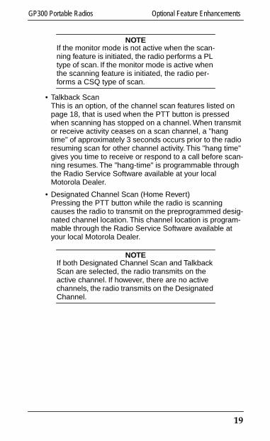
• Talkback ScanThis is an option, of the channel scan features listed on page 18, that is used when the PTT button is pressed when scanning has stopped on a channel. When transmit or receive activity ceases on a scan channel, a "hang time" of approximately 3 seconds occurs prior to the radio resuming scan for other channel activity. This "hang time" gives you time to receive or respond to a call before scan-ning resumes. The "hang-time" is programmable through the Radio Service Software available at your localMotorola Dealer.
• Designated Channel Scan (Home Revert)Pressing the PTT button while the radio is scanning causes the radio to transmit on the preprogrammed desig-nated channel location. This channel location is program-mable through the Radio Service Software available at your local Motorola Dealer.
NOTEIf both Designated Channel Scan and Talkback Scan are selected, the radio transmits on the active channel. If however, there are no active channels, the radio transmits on the Designated Channel.
19

Optional Feature Enhancements GP300 Portable Radios
GP300_owners.book Page 20 Thursday, August 7, 1997 9:49 AM
• Scan Talkback ToneThe Scan Talkback Tone feature enables you to find the last active channel received during scan mode. A beep is emitted when the channel selector knob is rotated to the last channel received during scan.
• Scan Nuisance DeleteWhen a conversation occurs and it is not your priority channel or designated scan channel, you can temporarily eliminate this channel from the scan list by pressing the side Scan Nuisance Delete button (on applicable mod-els). To add the deleted channel back to the prepro-grammed scan list, you must exit and reenter the scan function.
NOTEThe volume set feature is replaced whenever the side control button is programmed to oper-ate the Scan Nuisance Delete feature.
20

GP300 Portable Radios Optional Signalling Enhancements
GP300_owners.book Page 21 Thursday, August 7, 1997 9:49 AM
Optional Signalling Enhancements(Not Available on 2 Channel Models)
PTT IDWhen on a channel with the PTT ID feature, the radio transmits an identification code (unit ID) to the base sta-tion, indicating which portable is in operation. This code is sent whenever the PTT button is depressed. A sidetone is heard as the ID is being trans-mitted; when the tone ends, start your voice message in the standard manner. The LED glows red during the time that the ID is sent out.
Call Alert (Decode)Call Alert works similarly to tone-only pagers. When a Call Alert (page) is received, a series of 4 beep decode tones are heard while the LED flashes yellow. The LED continues flashing yellow and the alert tone continues until the call alert is acknowledged by the radio. If you transmit by push-ing the PTT button or change the rotary channel selector while a Call Alert signal is in progress, the LED stops flash-ing and the Call Alert tone is disabled.
Voice Selective Call (Decode)This feature operates like a standard pager providing a one-time voice message. When a Voice Selective Call is received by the radio, a one-time 2 beep decode tone is heard while the LED flashes yellow. The radio unmutes and the voice message is heard. The LED continues flashing yellow while the voice message is heard. The Voice Selective Call feature does not require any action to acknowledge the message and after the transmission is completed, the radio returns to normal operation.
21

Optional Signalling Enhancements GP300 Portable Radios
GP300_owners.book Page 22 Thursday, August 7, 1997 9:49 AM
Signalling and Channel Scan
Signalling and channel scan are compatible in the GP300 radio. However, during scan operation, a Voice Selective Call on a particular channel could be missed since the radio may not be checking that channel when the Voice Selective Call is being sent.
It is recommended that priority scan be selected and the signalling channel be designated the priority channel to improve the likelihood that the Voice Selective Call is received.
22

GP300 Portable Radios DTMF Telephone Interconnect
GP300_owners.book Page 23 Thursday, August 7, 1997 9:49 AM
DTMF Telephone Interconnect(Not Available on 2 Channel Models)
Dual Tone Multiple Frequency (DTMF) tones are encoded through the optional numeric keypad for access to the land-line telephone network and for remote control operation.
DTMF Telephone Interconnect
1. Press and hold the PTT but-ton.
2. Press the desired numeric digits on the DTMF keypad. As long as the PTT button is held while the digits are pressed, the corresponding DTMF tones are transmit-ted.
3. Alternatively, press the [PHN] button on the front of the radio to activate the numeric keypad for DTMF "live-dial" transmissions. The radio automatically keys and sends digits, stay-ing keyed for a programma-ble amount of time to wait for new DTMF digits.
4. Once the DTMF tones are transmitted, press the PTT button to transmit normally, without sending PTT-ID.
NOTEAfter 7 seconds of neither transmitting nor receiving, the radio automatically resets to nor-mal operation.
5. To return to normal operation at any time during the DTMF sequence, press the [PHN] button.
[PHN]
[MEM]
P1
P2
23

DTMF Telephone Interconnect GP300 Portable Radios
GP300_owners.book Page 24 Thursday, August 7, 1997 9:49 AM
DTMF Preprogrammed Access/Deaccess Codes
1. Press the [PHN] button to activate the numeric keypad for a DTMF transmission.
2. Press the [MEM] button, then select the [*] button for the preprogrammed access code or the [#] button for the preprogrammed deaccess code. The radio auto-matically keys and sends the desired string of digits.
3. After the string is transmitted, other digits may be sent by pressing the desired DTMF numeric buttons.
DTMF Preprogrammed Repertoire List
1. Press the [PHN] button to activate the numeric keypad for a DTMF transmission.
2. Press the [MEM] button, then select a digit [1 - 9]. The radio automatically keys and sends the desired string of digits.
3. After the string is transmitted, other digits may be sent by pressing the desired DTMF numeric buttons.
DTMF Last Number Redial
Manually dialed DTMF numeric digits are collected while the DTMF keypad function is active. To access this stored string of digits:
1. Press the [PHN] button to activate the numeric keypad for a DTMF transmission.
2. Press the [MEM] button, then select [0] numeric digit. The [0] number location is used for storage of the last number redial function. The radio automatically keys and sends out the stored DTMF digits. This set of num-bers is saved in memory until the radio is turned off or until another DTMF digit is dialed.
Dealer Programmed Control Buttons
Two dealer programmable control buttons, [P1] and [P2], which can be programmed through the Radio Service Soft-ware available at your local Motorola dealer are also pro-vided with the DTMF keypad model of the GP300. These additional control buttons function similarly to the buttons on the side of the radio.
24

GP300 Portable Radios Battery Information
GP300_owners.book Page 25 Thursday, August 7, 1997 9:49 AM
Battery InformationThe GP300 radio receives its power (7.5 V dc) from a rechargeable nickel-cadmium battery as listed in the acces-sories section. This battery, designed specifically for use in the GP300 radio, is a safe, dependable power source. Proper care of the battery will ensure its effectiveness and allow for peak performance of the radio.
Recharging Nickel-Cadmium Batteries
Recharge the battery before use to ensure optimum capac-ity and performance. The bat-tery was designed to be used only with a Motorola GP300 charger. Charging in non-Motorola equipment may lead to battery damage and void the battery warranty.
NOTEWhen charging a battery that is attached to a radio, always turn the radio off to ensure a full charge.
Charging Temperature
The battery should be about 77˚F (room temperature) whenever possible. Charging a cold battery (below 50˚F) may result in leakage of electrolyte, and ultimately, in fail-ure of the battery. Charging a hot battery (about 95˚F) results in reduced discharge capacity, affecting the performance of the radio. GP300 rapid rate battery chargers
25
Battery Information GP300 Portable Radios
GP300_owners.book Page 26 Thursday, August 7, 1997 9:49 AM
contain a temperature sensing circuit to ensure that the bat-tery is charged within these temperature limits. If the charger is not performing a rapid rate charge, the charger light flashes red to indicate that the battery is being charged at a slow trickle rate. For additional information on batteries and battery charging, refer to the battery charger informa-tion in the service manual.
Short CircuitCare should be taken to avoid external short-circuiting of the battery.
CAUTIONA sustained high rate discharge (e.g., a paper clip placed accidentally across the battery con-tacts) may permanently damage the battery, void the battery warranty, and create a burn or fire hazard.
Memory Effect (Reduced Charge Capacity)
The Memory Effect was a phenomenon which caused a temporary loss in battery capacity or voltage due to repeti-tive shallow discharging or low term overcharging. This Memory Effect has been virtually eliminated in Motorola batteries with the use of the latest in cell technology from our selected cell suppliers.
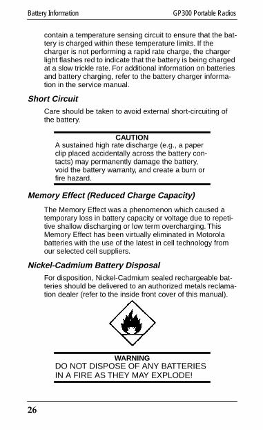
Nickel-Cadmium Battery DisposalFor disposition, Nickel-Cadmium sealed rechargeable bat-teries should be delivered to an authorized metals reclama-tion dealer (refer to the inside front cover of this manual).
WARNINGDO NOT DISPOSE OF ANY BATTERIES IN A FIRE AS THEY MAY EXPLODE!
26

GP300 Portable Radios Battery Chargers Operating Instructions
GP300_owners.book Page 27 Thursday, August 7, 1997 9:49 AM
Battery ChargersOperating Instructions
NOTETHE BATTERY IS SHIPPED FROM THE FAC-TORY UNCHARGED AND MUST BE CHARGED BEFORE USE.
WARNINGTO REDUCE RISK OF INJURY, CHARGE ONLY MOTOROLA NICKEL-CADMIUM TYPE RECHARGEABLE BATTERIES LISTED. OTHER TYPES OF BATTERIES MAY BURST, CAUSING PERSONAL INJURY AND DAMAGE.
• Do not expose charger to rain or snow.
• Use of an attachment not recommended or sold byMotorola may result in a risk of fire, electric shock, or injury to persons.
• To reduce risk of damage to the transformer and cord, pull by the transformer rather than the cord when unplugging the charger.
• Position cord so that it is not stepped on, tripped over, or otherwise subjected to damage or stress.
• An extension cord should not be used unless absolutely necessary. Use of an improper extension cord could result in a risk of fire and electric shock. If an extension cord must be used make sure:
(1) That pins on plug of extension cord are the same num-ber, size and shape as those on plug of charger,
(2) That extension cord is properly wired and in good con-dition, and
27

Battery Chargers Operating Instructions GP300 Portable Radios
GP300_owners.book Page 28 Thursday, August 7, 1997 9:49 AM
(3) The cord size is 18AWG for lengths of up to 100 feet, and 16AWG for lengths up to 150 feet.
• Do not operate charger with damaged cord or plug – replace them immediately.
• Do not operate charger if it has received a sharp blow, been dropped, or otherwise damaged in any way; take it to your local Motorola dealer.
• Do not disassemble charger; take it to your local Motorola dealer when service or repair is required. Incorrect reas-sembly may result in risk of electric shock or fire.
• To reduce risk of electric shock, unplug transformer from outlet before attempting any maintenance or cleaning. Turning off controls will not reduce this risk.
To Operate Charger
1. Insert the battery, with or without the radio, into the charger pocket. (Be sure that the radio is off).
2. Put plug into the charger and plug the transformer into the appropriate AC power outlet.
3. When the battery is fully inserted, the LED glows red. The LED continues to glow red while the battery is charging.
Plug
Transformer
28
GP300 Portable Radios Battery Chargers Operating Instructions
GP300_owners.book Page 29 Thursday, August 7, 1997 9:49 AM
4a. For Single-Unit Standard Rate Battery Chargers only: When a standard-charge battery reaches full charge, no change in the LED occurs (red glow remains). The battery fully charges in 10 hours.
NOTEYou can turn the radio on while it is in the charger and have it receive normally. However, allow at least 25% more time for the battery to reach full capacity. DO NOT TRANSMIT WHILE THE RADIO IS IN THE CHARGER.
4b. For Single-Unit and Multi-Unit Rapid-Charge Battery Chargers only: When charging a rapid-charge battery, the LED glows green indicating CHARGE COMPLETE when the battery reaches full charge. This LED also indicates that the battery is now charging at a trickle rate. A LED flashes red indicating that the battery may be out of "rapid charge range". The rapid charge auto-matically begins when the battery is within the correct range. Typical charge times for the Rapid-Charge Bat-tery Chargers are as follows:
1.0 Hr - 1.2 for High Capacity Battery
0.5 Hr - 0.8 Hr for Slimline Battery
NOTEA new battery or one which has not been used for several months may cause a premature fully charged indication. These batteries should be trickle charged over night before putting them into service.
5. If the LED does not glow red when the battery is inserted into the charger, check the battery and charger contacts to be sure they are clean. There are no user serviceable parts in the charger. If the charger fails to operate, contact your local Motorola dealer.
29

Accessories GP300 Portable Radios
GP300_owners.book Page 30 Thursday, August 7, 1997 9:49 AM
AccessoriesMotorola offers several accessories to increase communications effi-ciency. Many of the accessories available are listed below, but for a com-plete list, consult your local Motorola dealer.Antennas:HAD8450 — Orange 216-223 MHz VHF Antenna HAD9338 — Yellow 136-162 MHz VHF Antenna (Standard w/Unit)NAD6502 — Black 146-174 MHz VHF Antenna (Standard w/Unit)HAD9742 — Black 146-162 MHz VHF Stubby AntennaHAD9743 — Blue 162-174 MHz VHF Stubby AntennaHAD9728 — None Tunable Antenna Kit (136-174 MHz)HAD9934 — Pink 174-195 MHz VHF AntennaHAD9935 — Purple 195-208 MHz VHF AntennaNAE6523 — Black 470-520 MHz UHF Stubby AntennaNAE6483 — None 403-520 MHz UHF Antenna (Standard w/Unit)NAE6521 — Red 400-440 MHz UHF Stubby AntennaNAE6522 — Green 438-470 MHz UHF Stubby Antenna
NOTEEach of the color coded antennas listed is designed to cover only the frequency split indicated. Therefore, it is important to order the correct antenna (frequency split) to match a specific customer frequency.
Carrying Accessories:HLN9149 Swivel Belt Loop Adapter (for use with HLN9720, HLN9721,
HLN9750, HLN9970, and HLN9008)HLN9720 Standard Leather Carry Case w/Belt LoopHLN9873 Standard Leather Carry Case w/SwivelHLN9721 Slim Leather Carry Case w/Belt LoopHLN9076 Standard Molded Carry Holster w/Belt ClipHLN9750 Standard Nylon Carry CaseHLN9970 DTMF Standard Leather Carry Case w/Belt LoopHLN8411 DTMF Standard Leather Carry Case w/SwivelHLN8412 DTMF LCD Standard Leather Carry Case w/Swivel (Avail APD
Only)HLN9008 Leather Carry Case w/Belt Loop for fully approved
FM 1200 mAH BatteryHLN9009 Leather Carry Case w/Swivel for fully approved
FM 1200 mAH BatteryHLN9011 DTMF Carry Case w/Swivel for fully approved
FM 1200 mAH BatteryHLN9017 Nylon Carry Case for fully approved FM1200 mAH BatteryHLN8414 Chest Pack Carry HolderHLN9985 Waterproof BagHLN9724 Replacement 21/2" Belt ClipHLN8255 Spring Action 3” Belt ClipHLN8052 Wrist StrapNTN5243 Shoulder Strap (for use with all carry cases)Carrying Accessories Available Through APD Only:HLN9035 Replacement 21/2" Swivel Belt Loop (for use with HLN9873,
HLN8411, HLN8412, HLN9009, and HLN9011)
30

GP300 Portable Radios Accessories
GP300_owners.book Page 31 Thursday, August 7, 1997 9:49 AM
NTN5629 Replacement 3" Swivel Belt Loop (for use with same carryaccessories as 21/2" Belt Loop but with wider belts)
HLN9084 Replacement Strap for Molded Carry HolderHLN9973 Replacement Strap for Leather Carry CaseHLN9974 Replacement Strap for Nylon Carry CaseHLN9975 Replacement Strap for DTMF Carry CaseHLN9018 Replacement Strap for fully approved FM 1200 mAH Battery
Leather Carry CaseHLN9019 Replacement Strap for fully approved FM 1200 mAH Battery
Nylon Carry Case
Nickel-Cadmium Battery Chargers:HTN9630 110 Volt – 1 Hour Rapid Rate ChargerHTN9702 110 Volt – 10 Hour Standard Rate ChargerHTN9748 110 Volt – 6 Unit – 1 Hour Rapid Rate ChargerHTN9886 100 Volt – 1 Hour Rapid Rate ChargerHTN9938 100 Volt – 6 Unit – 1 Hour Rapid Rate ChargerHTN9802 220 Volt – 1 Hour Rapid Rate Charger (European Plug)HTN9804 220 Volt – 10 Hour Standard Rate Charger (European Plug)HTN9803 240 Volt – 1 Hour Rapid Rate Charger (U.K. Plug)HTN9805 240 Volt – 10 Hour Standard Rate Charger (U.K. Plug) HTN9812 240 Volt – 6 Unit – 1 Hour Rapid Rate Charger (U.K. Plug)HLN9719 1 Hour Vehicular Charger Adapter/Bracket (12 volt
for use with HTN9630, HTN9802 or HTN9803 RapidRate Chargers)
HLN9944 Wall Mounting Bracket for Multi Unit Charger (Avail. APD Only)HKN8036 Battery Eliminator
Batteries:HNN9628 1200 mAH Standard BatteryHNN8133 1200 mAH Limited FM BatteryHNN8308 600 mAH Slimline BatteryHNN9808 600 mAH (Fully Approved FM Slim Battery)HNN9701 1200 mAH (Fully Approved FM Battery)
Audio/RF Accessories:HMN9725 Remote Speaker MicrophoneHMN9727 Earpiece Without Volume Control (plastic earloop)HMN9752 Earpiece With Volume Control (plastic earloop)HMN9754 2 Piece Surveillance Microphone (plastic earloop)HMN9787 Headset w/Swivel Boom MicrophoneBDN6647 Medium Weight Headset w/ Boom MicrophoneBDN6648 Heavy Weight Headset w/Noise Cancelling Boom Mic.BDN6646 Ear MicrophoneBDN6706 Ear Microphone with VOX Interface (external VOX included)BDN6720 Flexiable Ear ReceiverHLN8096 Audio Accessory ClampHLN9756 BNC – RF Adapter (for use with GP300 models only)50-80386B90 Rubber Ear Inserts (for earpieces with older metal
earloop - 25 per package50-80371E73 Rubber Ear Inserts (for earpieces with plastic earloops
25 per package
31
Belt Clip Installation Instructions GP300 Portable Radios
GP300_owners.book Page 32 Thursday, August 7, 1997 9:49 AM
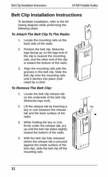
Belt Clip Installation InstructionsTo facilitate installation, refer to the fol-lowing diagram while performing the following steps:
To Attach The Belt Clip To The Radio:
1. Locate the mounting rails on the back side of the radio.
2. Position the belt clip, Motorola logo facing up, so the logo end of the clip is nearest the mounting rails, and the other end of the clip is toward the bottom of the radio.
3. Align the mounting rails with the grooves in the belt clip. Slide the belt clip onto the mounting rails until it latches into place (indi-cated by a click)
To Remove The Belt Clip:
1. Locate the belt clip release tab on the underside of the belt clip (Motorola logo end).
2. Lift the release tab by inserting a key or coin between the release tab and the back surface of the radio.
3. While holding the key or coin firmly under the release tab, pry up until the belt clip slides slightly toward the bottom of the radio.
4. With the belt clip fully released (when the release tab is pressed against the inside surface of the belt clip), slide the belt clip off the mounting rails.
Tab
32

GP300 Portable Radios For Use in Hazardous Atmospheres
GP300_owners.book Page 33 Thursday, August 7, 1997 9:49 AM
For Use in Hazardous AtmospheresFor information referencing the Factory Mutual approved GP300 Models, Options and Accessories, refer to theFactory Mutual Approval Manual Supplement (6880902Z27).
33

Troubleshooting GP300 Portable Radios
GP300_owners.book Page 34 Thursday, August 7, 1997 9:49 AM
TroubleshootingIf you experience difficulty, check the following items before requesting service.
1. Review steps under OPERATION.
2. Be sure the rotary channel selector switch is set to the correct channel.
3. Replace or recharge the battery.
4. If reception is poor, check the antenna. It must be undamaged and operated in the vertical position for best reception.
5. Try several different operating locations, especially when operating the radio inside buildings.
6. Check transmitter by transmitting to another portable radio or communications receiver. If the receiver has a signal strength (‘S’) meter, make comparison readings against another portable radio.
34

GP300 Portable Radios Service
GP300_owners.book Page 35 Thursday, August 7, 1997 9:49 AM
ServiceBecause this unit contains a radio transmitter, federal law prohibits anyone from making any internal adjustments to the transmitter unless specifically licensed to do so by gov-ernment regulations. If your radio fails to operate, contact your local Motorola dealer.
Proper repair and maintenance procedures assure efficient operation and long life for this radio.
35

General Radio Care GP300 Portable Radios
GP300_owners.book Page 36 Thursday, August 7, 1997 9:49 AM
General Radio Care1. Avoid physical abuse of your radio such as carrying it
by the antenna or remote microphone.
2. Wipe the battery contacts with a lint-free cloth to remove dirt, grease, or other material which may pre-vent good electrical connections.
3. When not in use, keep the accessory connector cov-ered with the protective cap.
4. Clean the radio exterior using a cloth moistened with water. See Caution.
CAUTIONUse of chemicals such as detergents, alcohol, aerosol spray, and/or petroleum products may be harmful and damage the radio housing and cover. Refer to the inside front cover of this manual.
36

GP300 Portable Radios Safety Information
GP300_owners.book Page 37 Thursday, August 7, 1997 9:49 AM
Safety InformationThe Federal Communications Commission (FCC) with its action in General Docket 79-144, March 13, 1985 has adopted a safety standard for the human exposure to radio frequency (RF) electromagnetic energy emitted by FCC-regulated equipment. Proper operation of this radio will result in user exposure substantially below the FCC recom-mended limits.
Your hand-held portable radio should be held in a vertical position with the microphone 2.5 to 5 cm (1 to 2 inches) from the mouth and the antenna should be kept 2.5 to 5 cm (1 to 2 inches) away from the head or body when trans-mitting. For body worn opera-tion, the antenna should be kept at least 2.5 cm (one inch) away from the body when transmitting.
DO NOT hold the transmit PTT button on when not actually desiring to transmit.
DO NOT allow children to play with any radio equipment containing a transmitter.
DO NOT operate a portable transmitter near unshielded electrical blasting caps or in an explosive atmosphere unless it is a type especially qualified for such use.
DO NOT operate the radio with a headset or other audio accessories at high volume levels. Hearing experts advise against continuous high volume operation. If you experi-ence a ringing in your ears, reduce the volume level or dis-continue use.
37
Computer Software Copyrights GP300 Portable Radios
GP300_owners.book Page 38 Thursday, August 7, 1997 9:49 AM
Computer Software CopyrightsThe Motorola products described in this manual may include copyrighted Motorola computer programs stored in semiconductor memories or other media. Laws in the United States and other countries preserve for Motorola certain exclusive rights for copyrighted computer programs, including the exclusive right to copy or reproduce in any form, the copyrighted computer program. Accordingly, any copyrighted Motorola computer programs contained in the Motorola products described in this manual may not be cop-ied or reproduced in any manner without the express writ-ten permission of Motorola. Furthermore, the purchase of Motorola products shall not be deemed to grant, either directly or by implication, estoppel or otherwise, any license under the copyrights, patents or patent applications of Motorola, except for the normal non-exclusive royalty-free license to use that arises by operation of law in the sale of a product.
38
GP300 Portable Radios Licensing Information
GP300_owners.book Page 39 Thursday, August 7, 1997 9:49 AM
Licensing InformationYour Motorola radio operates on FM radio communication frequencies and is subject to the Rules and Regulations of the Local Communications Governing Agencies. These agencies may require that all operators using Private Land Mobile or General Mobile Radio frequencies obtain a radio license before operating their equipment. The operator receives a license for use of the radio equipment under a specific eligibility and on a particular frequency or set of fre-quencies. To determine eligibility for use of Private Land Mobile Service frequencies, contact your local communica-tions governing agency. They are able to supply information required to properly obtain and complete the license appli-cation form:
Agency addresses for several countries are listed below:
In the United States contact:
Federal Communications CommissionConsumer AssistanceBranch License DivisionGettysburg, PA 17326Tel. (717) 337-1212
In Canada contact:
Head Equipment Approval UnitDepartment of Communications1241 Clyde AvenueOttawa, Ontario K2C-1Y3CanadaTel. (613) 998-5968
In the United Kingdom contact:
Radio Communications AgencyP.O. Box 20LondonSE1 8TZTel. 71 215 2152
39

Licensing Information GP300 Portable Radios
GP300_owners.book Page 40 Thursday, August 7, 1997 9:49 AM
In Mexico contact:
Secretaria De Communicaciones Y TransportesDireccion General De PoliticasY Normas De CommunicacionesAv. Eugenia No. 197-5o. PisoMexico, D.F. 06700
In Singapore contact:
Telecommunications Authority of Singapore3rd Storey Comcenter31 Exeter RoadSingapore, 0923Singapore
In Japan contact:
Communications Research LaboratoryMinistry of Posts & TelecommunicationsMKK Building7-2, 5-chromeYashio, ShinagawakuTokyo, 140 Japan
In Hong Kong contact:
Hong Kong Telecommunications AuthorityTelecommunications BranchPost Office, Hong Kong6/F Sincere Building173 Des Voeux Road CentralHong Kong
40