Embed Size (px)
Citation preview

OPERATORS TEK .AwA, 070-6558-01 Product G~OUD 46
PORTABLE OSCILLOSCOPE OPERATORS
Please Check for CHANGE INFORMATION at the Rear of This Manual
L QJ First Printing JAN 1989 3 Revised JUN 1989
COMMITTED TO EXCELLEWE

Copyright O 1987,1889 Tektronix, lnc. All rights reserved. Contents of this publication may not be reproduced in any form without the written permis- sion of Tektronix, Inc.
Products of Tektronix, Inc, and its subsidiaries are covered by U.S. and foreign patents andlor pending patents.
TEKTRONIX, TEK, SCOPE-MOBILE and are registered trademarks of Tektronix, Inc.
Printed in U.S.A. Specification and price change privileges are reserved.
INSTRUMENT SERIAL NUMBERS
Each instrument has a serial number on a panel insert, tag, or stamped on the chassis. The first number or letter designates the country of manufac- ture. The last five digits of the serial number are assigned sequentially and are unique to each instrument. Those manufactured in the United States have six unique digits. The country of manufacture is identified as follows:
BOO0000 Tektronix, Inc., Beaverton, Oregon, U.S.A.
G I 00000 Tektronix Guernsey, Ltd. , Channel Islands
E200000 Tektronix United Kingdom, Ltd., Marlow
J300000 SonyITektronix, Japan
H700000 Tektronix Holland, NV, Heerenveen, The Netherlands
HKOOOOO Tektronix, Inc. Hong Kong

Certificate of the Manufacturer/lmporter
We hereby certify that the
2245A OSCILLOSCOPE AND ALL INSTALLED OPTIONS
complies with the RF Interference Suppression requirements of AmtsbLVfg 104611 984.
The German Postal Service was notified that the equipment is being marketed.
The German Postal Service has the right to re-test the series and to verify that it complies.
TEKTRONIX
Bescheinigung des Herstellers/lmporteurs
Hiermit wird bescheinigt, dad derldieldas
2245A OSCILLOSCOPE AND ALL INSTALLED OPTIONS
in iJbereinstimmung mit den Bestimmungen der Amtsblatt-Verfugung 104611984 funkentstort ist.
Der Deutschen Bundespost wurde das lnverkehrbringen dieses Gerates angezeigt und die Berechtigung zur Uberprufung der Serie auf Einhalten der Bestimmungen eingeraumt.
TEKTRONIX

NOTICE to the userloperator:
The German Postal Service requires that Systems assembled by the operatorluser of this instrument must also comply with Postal Regulation, Vfg. 104611984, Par. 2, Sect. 1.
HlNWElS fur den BenutzerIBetreiber:
Die vom Betreiber zusammengestellte Anlage, innerhalb derer dies Gerat eingesetzt wird, mu8 ebenfalls den Voraussetzungen nach Par. 2, Ziff. 1 der Vfg. lO46Il984 genugen.
NOTICE to the userloperator:
The German Postal Service requires that this equipment, when used in a test setup, may only be operated if the requirements of Postal Regulation, Vfg. 104611 984, Par. 2, Sect. 1.7.1 are complied with.
HlNWElS fur den BenutzerIBetreiber:
Dies Gerat darf in MeAaufbauten nur betrieben werden, wenn die Voraussetzungen des Par. 2, Ziff. 1.7.1 der Vfg. lO46Il984 eingehalten werden.

TABLE OF CONTENTS
. . . . . . . . . . . . . . . . . . . . . . . . . . . . . . . . . . . . . . LIST O F ILLUSTRATIONS vi . . . . . . . . . . . . . . . . . . . . . . . . . . . . . . . . . . . . . . . . . . . . . LIST O F TABLES vii
. . . . . . . . . . . . . . . . . . . . . . . . . . . . . OPERATORS SAFETY SUMMARY viii
SECTION 1-INTRODUCTION
PRODUCT OVERVIEW . . . . . . . . . . . . . . . . . . . . . . . . . . . . . . . . . . . . . . . . 1-1
Description . . . . . . . . . . . . . . . . . . . . . . . . . . . . . . . . . . . . . . . . . . . . . . . . . . 1-1
Standard Accessories . . . . . . . . . . . . . . . . . . . . . . . . . . . . . . . . . . . . . . . . . 1-3
PREPARATION FOR USE . . . . . . . . . . . . . . . . . . . .. . . . . . .. . . . . . . . . . . 1-4
Safety . . . . . . . . . . . . . . . . . . . . . . . . . . . . . . . . . . . . . . . . . . . . . . . . . . 1-4
. . . . . . . . . . . . . . . . . . . . . . . . . . . . . . . . . . . . . . . . . . . . . . . . . . . . Line Fuse 1-4
Line Voltage and Power Cord . . . . . . . . . . . . . . . . . . . . . . . . . . . . . . . . . . 1-4
. . . . . . . . . . . . . . . . . . . . . . . . . . . . . . . . . . . . . . . . . . . . Instrument Cooling 1-6
Start-up . . . . . . . . . . . . . . . . . . . . . . . . . . . . . . . . . . . . . . . . . . . . . . . . . . . . 1-6
Repackaging for Shipment . . . . . . . . . . . . . . . . . . . . . . . . . . . . . . . . . . . . . 1-8
SECTION 2.CONTROLS. CONNECTORS. AND INDICATORS
. . . . . . . . . . . . . . . . . . . . . . Crt. Power. and Display ... . . . . . . . . . . . . . 2-1
Vertical . . . . . . . . . . . . . . . . . . . . . . . . . . . . . . . . . . . . . . . . . . . . . . . . . . . . . 2-3
Horizontal . . . . . . . . . . . . . . . . . . . . . . . . . . . . . . . . . . . . . . . . . . . . . . . . . . . 2-7
Trigger . . . . . . . . . . . . . . . . . . . . . . . . . . . . . . . . . . . . . . . . . . . . . . . . . . . . . 2-11
A Trigger Modes . . . . . . . . . . . . . . . . . . . . . . . . . . . . . . . . . . . . . . . . . . 2-13 B Trigger Modes . . . . . . . . . . . . . . . . . . . . . . . . . . . . . . . . . . . . . . . . . . 2-14
Rear Panel . . . . . . . . . . . . . . . . . . . . . . . . . . . . . . . . . . . . . . . . . . . . . . . . . . 2-17
Measurements and Auto Setup Controls . . . . . . . . . . . . . . . . . . . . . . . . 2-18
2245A Operators

SECTION 3-OPERATORS FAMILIARIZATION
. . . . . . . . . . . . . . . . . . . . . . . . . . . . . . . . . . . . . . . . . . . BASIC OPERATION 3-1
Readout Display . . . . . . . . . . . . . . . . . . . . . . . . . . . . . . . . . . . . . . . . . . . . . . 3-1
Gratlcule . . . . . . . . . . . . . . . . . . . . . . . . . . . . . . . . . . . . . . . . . 3-1
Connecting Input Signals . . . . . . . . . . . . . . . . . . . . . . . . . . . . . . . . . . . . . . . 3-3
Grounding . . . . . . . . . . . . . . . . . . . . . . . . . . . . . . . . . . . . . . . . . . . . . . . . . 3-3 Probes . . . . . . . . . . . . . . . . . . . . . . . . . . . . . . . . . . . . . . . . . . . . . . . . . . . . 3-4 Coaxialcables . . . . . . . . . . . . . . . . . . . . . . . . . . . . . . . . . . . . . . . . . . . . . 3-4 ExternalTrlggerlng . . . . . . . . . . . . . . . . . . . . . . . . . . . . . . . . . . . . . . . . . 3-4
Autosetup . . . . . . . . . . . . . . . . . . . . . . . . . . . . . . . . . . . . . . . . . . . . . . . . . . 3-5
MIN SETUP . . . . . . . . . . . . . . . . . . . . . . . . . . . . . . . . . . . . . . . . . . . . . . . . . . 3-5
MEASUREMENT SYSTEM . . . . . . . . . . . . . . . . . . . . . . . . . . . . . . . . . . . . . 3-5
Cursor Volts Measurements . . . . . . . . . . . . . . . . . . . . . . . . . . . . . . . . . . . . 3-5
Tlme Measurements . . . . . . . . . . . . . . . . . . . . . . . . . . . . . . . . . . . . . . . . . . 3-6
Behavior for Horizontal Mode Changes . . . . . . . . . . . . . . . . . . . . . . . . . . . 3-7
Measurement Compatibility and Error Messages . . . . . . . . . . . . . . . . . . 3-8
Measurements in Single Sequence Mode . . . . . . . . . . . . . . . . . . . . . . . . . 3-8
. . . . . . . . . . . . . . . . . . . . . . . . . . . . . . . . . . . . . . . . Service Menu Features 3-9
Configure Menu . . . . . . . . . . . . . . . . . . . . . . . . . . . . . . . . . . . . . . . . . . . 3-10 Self Cal Measurements . . . . . . . . . . . . . . . . . . . . . . . . . . . . . . . . . . . . 3-11
. . . . . . . . . . . . . . . . . . . . . . . . . . . . . . . . . . . . . Internal Settlngs Menu 3-12
SECTION 4-OPERATOR CHECKS A N D ADJUSTMENTS
Introduction . . . . . . . . . . . . . . . . . . . . . . . . . . . . . . . . . . . . . . . . . . . . . . . . . . 4-1
Initial Setup . . . . . . . . . . . . . . . . . . . . . . . . . . . . . . . . . . . . . . . . . . . . . . . . . . 4-1
Auto Setup Function . . . . . . . . . . . . . . . . . . . . . . . . . . . . . . . . . . . . . . . . . . 4-2
Trace Rotation Adjustment . . . . . . . . . . . . . . . . . . . . . . . . . . . . . . . . . . . . . 4-3
Probe Low-Frequency Compensation . . . . . . . . . . . . . . . . . . . . . . . . . . . . 4-3
Vertical Deflection Check . . . . . . . . . . . . . . . . . . . . . . . . . . . . . . . . . . . . . . 4-5
Timing Checks . . . . . . . . . . . . . . . . . . . . . . . . . . . . . . . . . . . . . . . . . . . . . . . 4-6
SECTION 5-BASIC APPLICATIONS
Introduction . . . . . . . . . . . . . . . . . . . . . . . . . . . . . . . . . . . . . . . . . . . . . . . . . . 5-1
Voltage Measurement Cursors . . . . . . . . . . . . . . . . . . . . . . . . . . . . . . . . . 5-1
Voltage Difference . . . . . . . . . . . . . . . . . . . . . . . . . . . . . . . . . . . . . . . . . 5-1
2245A Operators

. . . . . . . . . . . . . . . . . . . . . . . . . . . . . . . . . . . . Time Measurement Cursors 5-3
Time Difference . . . . . . . . . . . . . . . . . . . . . . . . . . . . . . . . . . . . . . . . . . . . 5-3 Period Measurement . . . . . . . . . . . . . . . . . . . . . . . . . . . . . . . . . . . . . . . . 5-4 Frequency Measurement . . . . . . . . . . . . . . . . . . . . . . . . . . . . . . . . . . . . 5-5
. . . . . . . . . . . . . . . . . . . . . . . . . . . . . . . . . . . Rise-Time Measurements 5-6 Phase Measurements . . . . . . . . . . . . . . . . . . . . . . . . . . . . . . . . . . . . . . 5-8
Time Delay Measurement . . . . . . . . . . . . . . . . . . . . . . . . . . . . . . . . . . . . . 5-11
Add Mode . . . . . . . . . . . . . . . . . . . . . . . . . . . . . . . . . . . . . . . . . . . . . . . . . . 5-14
SECTION 6-PERFORMANCE CHARACTERISTICS
Introduction . . . . . . . . . . . . . . . . . . . . . . . . . . . . . . . . . . . . . . . . . . . . . . . . . . 6-1
. . . . . . . . . . . . . . . . . . . . . . . . . . . . . Recommended Calibration Schedule 6-1
SECTION 7-PERFORMANCE CHECK PROCEDURE
INTRODUCTION . . . . . . . . . . . . . . . . . . . . . . . . . . . . . . . . . . . . . . . . . . . . . . 7-1
. . . . . . . . . . . . . . . . . . . . . . . . . . . . . . . . . . . . . . Test Equipment Required 7-1
. . . . . . . . . . . . . . . . . . . . . . . . . . . . . . . . . . . . Performance Check interval 7-1
Preparation . . . . . . . . . . . . . . . . . . . . . . . . . . . . . . . . . . . . . . . . . . . . . . . . . . 7-1
INDEX TO PERFORMANCE CHECK PROCEDURE . . . . . . . . . . . . . . . . . 7-6
DISPLAY . . . . . . . . . . . . . . . . . . . . . . . . . . . . . . . . . . . . . . . . . . . . . . . . . . . . 7-8
. . . . . . . . . . . . . . . . . . . . . . . . . . . . . . . . . . . . . . . . . TRACE ROTATION 7-8 Geometry . . . . . . . . . . . . . . . . . . . . . . . . . . . . . . . . . . . . . . . . . . . 7-9
VERTICAL . . . . . . . . . . . . . . . . . . . . . . . . . . . . . . . . . . . . . . . . . . . . . . . . . . 7-10
Input COUPLING Functional Check . . . . . . . . . . . . . . . . . . . . . . . . . . . 7-10 CH 1 and CH 2 VOLTSIDIV Trace Shift . . . . . . . . . . . . . . . . . . . . . . 7-11 CH 3 and CH 4 VOLTSIDIV Trace Shift . . . . . . . . . . . . . . . . . . . . . . 7-12
. . . . . . . . . . . . . . . . . . CH 1 and CH 2 VAR VOLTSIDIV Trace Shift 7-12 CH 1 and CH 2 Input COUPLING Trace Shift . . . . . . . . . . . . . . . . . . 7-13 CH 2 INVERT Trace Shift . . . . . . . . . . . . . . . . . . . . . . . . . . . . . . . . . . 7-13
. . . . . . . . . . . . . . . . . . . . . . CH 1 and CH 2 VAR VOLTSIDIV Range 7-13 . . . . . . . . . . . . . . . . . . . . . . . . . . . . . . . . . . . Low-Frequency Linearity 7-14
CH 1 and CH 2 Vertical Deflection Accuracy . . . . . . . . . . . . . . . . . . 7-15 CH 3 and CH 4 Vertical Deflection Accuracy . . . . . . . . . . . . . . . . . . 7-16 ADD Mode and CH 2 INVERT Deflection Accuracy . . . . . . . . . . . . . 7-17 Vertical POSITION Range (all channels) . . . . . . . . . . . . . . . . . . . . . 7-18 CH 1 to CH 2 Signal Delay Match . . . . . . . . . . . . . . . . . . . . . . . . . . . . 7-19 CH 1 to CH 4 Signal Delay Match . . . . . . . . . . . . . . . . . . . . . . . . . . . . 7-19 CH 3 to CH 4 Signal Delay Match . . . . . . . . . . . . . . . . . . . . . . . . . . . . 7-20 Ch 1 and CH 2 Vertical Bandwidth . . . . . . . . . . . . . . . . . . . . . . . . . . 7-21
. . . . . . . . . . . . . . . . . . . . . . . . . . . CH 3 and CH 4 Vertical Bandwidth 7-22
2245A Operators iii

. . . . . . . . . . . . . . . . . . . . . . SCOPE BW (Bandwidth Limit) Accuracy 7-22 . . . . . . . . . . . . . . . . . . . . . . . . . . . . . Common-Mode Rejection Ratio 7-23
. . . . . . . . . . . . . . . . . . . . . . . . . . . . . . . . . . . . . . . . . . Channel Isolation 7-24 . . . . . . . . . . . . . . . . . . . . . . . . . . . . . AC-Coupled Lower -3 dB Point 7-25
. . . . . . . . . . . . . . . . . . . . . . . . . . . . . . Vertical ALT and CHOP Modes 7-26 . . . . . . . . . . . . . . . . . . . . . . . . . . . . . . . BEAM FIND Functional Check 7-26
. . . . . . . . . . . . . . . . . . . . . . . . . . . . . . . . . . A and B Trace Separation 7-27
. . . . . . . . . . . . . . . . . . . . . . . . . . . . . . . . . . . . . . . . . . . . . . . . TRIGGERING 7-28
. . . . . . . . . . . . . . . . . . . . . . . . . . . . . . . . . . . 500 Hz Trigger Sensitivity 7-27 . . . . . . . . . . . . . . . . . . . . . . . . . . . . . . . . . . 500 kHz Trigger Sensitivity 7-28 . . . . . . . . . . . . . . . . . . . . . . . . . . . . . . . . . . 25 MHz Trigger Sensitivity 7-30 . . . . . . . . . . . . . . . . . . . . . . . . . . . . . . . . . 150 MHz Trigger Sensitivity 7-31
. . . . . . . . . . . . . . . . . . . . . . . . . . . . . . . . . . . . . . . . Single Sweep Mode 7-32 Trigger LEVEL Control Range . . . . . . . . . . . . . . . . . . . . . . . . . . . . . . . 7-33 TV Field Trigger Sensitivity . . . . . . . . . . . . . . . . . . . . . . . . . . . . . . . . . 7-34 TV Line Trigger Sensitivity . . . . . . . . . . . . . . . . . . . . . . . . . . . . . . . . . . 7-34 Line Trigger Functional Check . . . . . . . . . . . . . . . . . . . . . . . . . . . . . . . 7-35
HORIZONTAL . . . . . . . . . . . . . . . . . . . . . . . . . . . . . . . . . . . . . . . . . . . . . . . 7-36
A and B Sweep Length . . . . . . . . . . . . . . . . . . . . . . . . . . . . . . . . . . . . . 7-36 Horizontal POSITION Range . . . . . . . . . . . . . . . . . . . . . . . . . . . . . . . . . 7-37
. . . . . . . . . . . . . . . . . . . . . . . . . . . . . . . . . . . . . . VAR SECIDIV Range 7-38
. . . . . . . . . . . . . . . . . . . . . . . . . . . . . . . . . . . . . . Magnifier Registration 7-38 . . . . . . . . . . . . . . . . . . . . . . . A and B Timing Accuracy and Linearity 7-38
A and B Magnified Timing Accuracy and Linearity . . . . . . . . . . . . . . 7-41 Delay TimeJit ter . . . . . . . . . . . . . . . . . . . . . . . . . . . . . . . . . . . . . . . . . . 7-42 Delay Time Accuracy . . . . . . . . . . . . . . . . . . . . . . . . . . . . . . . . . . . . . . 7-43 Delay Time Position Range . . . . . . . . . . . . . . . . . . . . . . . . . . . . . . . . . 7-44 X-AXIS Gain Accuracy . . . . . . . . . . . . . . . . . . . . . . . . . . . . . . . . . . . . . 7-44 X-Y Phase Difference . . . . . . . . . . . . . . . . . . . . . . . . . . . . . . . . . . . . . . 7-45 X-Axis Bandwldth . . . . . . . . . . . . . . . . . . . . . . . . . . . . . . . . . . . . . . . . . 7-45
. . . . . . . . . . . . . . . . . . . . . . . . . . . . . . . . . . . MEASUREMENT CURSORS 7-46
. . . . . . . . . . . . . . . . . . I+ SEC - 4 and I c 1 ISEC +I Cursor Accuracy 7-46 . . . . . . . . . . . . . . . . . . . . . . . . . . . . . . It VOLTS 4 Cursor Accuracy 7-47
EXTERNAL Z-AXIS, PROBE ADJUST. AND . . . . . . . . . . . . . . . . . . . . . . . . . . . . . . . . . . . AUTO SETUP FUNCTIONS 7-48
. . . . . . . . . . . . . . . . . . . . . . . . . . . . . . . . Check External Z-Axis Input 7-48 PROBE ADJUST Output . . . . . . . . . . . . . . . . . . . . . . . . . . . . . . . . . . . . 7-49 AUTO SETUP Functional Check . . . . . . . . . . . . . . . . . . . . . . . . . . . . . 7-49
OPTION 15 . . . . . . . . . . . . . . . . . . . . . . . . . . . . . . . . . . . . . . . . . . . 7-50
Signal Output . . . . . . . . . . . . . . . . . . . . . . . . . . . . . . . . . . . . . . . . . . . . . 7-50 A GATE Output . . . . . . . . . . . . . . . . . . . . . . . . . . . . . . . . . . . . . . . . . . . 7-51
2245A Operators

SECTION 8-OPTIONS A N D ACCESSORIES
Introduction . . . . . . . . . . . . . . . . . . . . . . . . . . . . . . . . . . . . . . . . . . . . . . . . . . 8-1
Options A1 -A5 International Power Cords . . . . . . . . . . . . . . . . . . . . . . . . 8-1
OPTION 15 . . . . . . . . . . . . . . . . . . . . . . . . . . . . . . . . . . . . . . . . . . . . . . . . . . 8-1
Standard Accessories . . . . . . . . . . . . . . . . . . . . . . . . . . . . . . . . . . . . . . . . . 8-1
Optional Accessories . . . . . . . . . . . . . . . . . . . . . . . . . . . . . . . . . . . . . . . . . . 8-2
Instrument Enhancements . . . . . . . . . . . . . . . . . . . . . . . . . . . . . . . . . . . 8-2 Transportation Aids . . . . . . . . . . . . . . . . . . . . . . . . . . . . . . . . . . . . . . . . . 8-2 Cameras . . . . . . . . . . . . . . . . . . . . . . . . . . . . . . . . . . . . . . . . . . . . . . . . . . 8-2 Probes . . . . . . . . . . . . . . . . . . . . . . . . . . . . . . . . . . . . . . . . . . . . . . . . . . . . 8-3 Viewing Hoods . . . . . . . . . . . . . . . . . . . . . . . . . . . . . . . . . . . . . . . . . . . . . 8-3
APPENDIX A . AUTO-SETUPIMIN SETUP Control Sett ings
APPENDIX B . FACTORY SETINGS
CHANGE INFORMATION
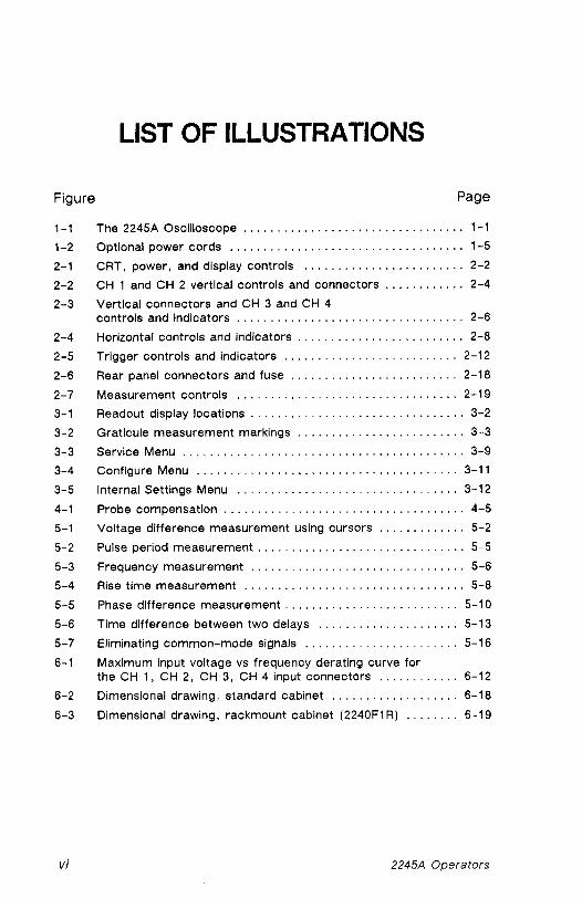
LIST OF ILLUSTRATIONS
Figure Page
. . . . . . . . . . . . . . . . . . . . . . . . . . . . . . . . . 1-1 The 2245A Oscilloscope 1-1
. . . . . . . . . . . . . . . . . . . . . . . . . . . . . . . . . . . 1-2 Optional power cords 1-5
. . . . . . . . . . . . . . . . . . . . . . . . 2-1 CRT. power. and display controls 2-2
. . . . . . . . . . . . 2-2 CH 1 and CH 2 vertical controls and connectors 2-4
2-3 Vertical connectors and CH 3 and CH 4 . . . . . . . . . . . . . . . . . . . . . . . . . . . . . . . . . . controls and indicators 2-6
2-4 Horizontal controls and indicators . . . . . . . . . . . . . . . . . . . . . . . . . 2-8
. . . . . . . . . . . . . . . . . . . . . . . . . . 2-5 Trigger controls and indicators 2-12
2-6 Rear panel connectors and fuse . . . . . . . . . . . . . . . . . . . . . . . . . 2-18
. . . . . . . . . . . . . . . . . . . . . . . . . . . . . . . . . 2-7 Measurement controls 2-19
3-1 Readout display locations . . . . . . . . . . . . . . . . . . . . . . . . . . . . . . . . 3-2
3-2 Graticuie measurement markings . . . . . . . . . . . . . . . . . . . . . . . . . 3-3
3-3 Service Menu . . . . . . . . . . . . . . . . . . . . . . . . . . . . . . . . . . . . . . . . . . 3-9
3-4 Configure Menu . . . . . . . . . . . . . . . . . . . . . . . . . . . . . . . . . . . . . . . 3-11
3-5 Internal Settings Menu . . . . . . . . . . . . . . . . . . . . . . . . . . . . . . . . . 3-12
4-1 Probe compensation . . . . . . . . . . . . . . . . . . . . . . . . . . . . . . . . . . . . 4-5
5-1 Voltage difference measurement using cursors . . . . . . . . . . . . . 5-2
5-2 Pulse period measurement . . . . . . . . . . . . . . . . . . . . . . . . . . . . . . . 5-5
5-3 Frequency measurement . . . . . . . . . . . . . . . . . . . . . . . . . . . . . . . . 5-6
5-4 Rise time measurement . . . . . . . . . . . . . . . . . . . . . . . . . . . . . . . . . 5-8
5-5 Phase difference measurement . . . . . . . . . . . . . . . . . . . . . . . . . . 5-10
5-6 Time difference between two delays . . . . . . . . . . . . . . . . . . . . . 5-13
5-7 Eliminating common-mode signals . . . . . . . . . . . . . . . . . . . . . . . 5-16
6-1 Maximum input voltage vs frequency derating curve for the CH 1. CH 2. CH 3. CH 4 input connectors . . . . . . . . . . . . 6-12
6-2 Dimensional drawing. standard cabinet . . . . . . . . . . . . . . . . . . . 6-18
6-3 Dimensional drawing. rackmount cabinet (2240F1 R) . . . . . . . . 6-19
2245A Operators

LIST OF TABLES
Table Page
. . . . . . . . . . . . . . . . . . . . . . . . . . . . . . . . VERT Trigger SOURCE 2-16
Behavior for Horizontal MODE Changes . . . . . . . . . . . . . . . . . . . . 3-7
. . . . . . . . . . . . . . . . . . . . . . . . . . . . . . . . Electrical Characteristics 6-2
Environmental Characteristics . . . . . . . . . . . . . . . . . . . . . . . . . . . 6-13
Mechanical Characteristics . . . . . . . . . . . . . . . . . . . . . . . . . . . . . 6-15
. . . . . . . . . . . . . . . . . . . . . . . . . . . . . . . . Test Equipment Required 7-3
Signal-to-Graticule Accuracy . . . . . . . . . . . . . . . . . . . . . . . . . . . 7-16
Settings for Timing Accuracy Checks . . . . . . . . . . . . . . . . . . . . 7-40
Delay Time Accuracy . . . . . . . . . . . . . . . . . . . . . . . . . . . . . . . . . . 7-43
AUTO-SETUP Control Settings . . . . . . . . . . . . . . . . . . . . . . . . . . . A-1
MIN SETUP Control Settings . . . . . . . . . . . . . . . . . . . . . . . . . . . . . A-4
Factory Settings . . . . . . . . . . . . . . . . . . . . . . . . . . . . . . . . . . . . . . . B-1
2245A Operators vii

OPERATORS SAFETY SUMMARY
The safety information in this summary is for operating personnel. Warn- ings and cautions will also be found throughout the manual where they apply.
Terms in this Manual
CAUTION statements identify conditions or practices that could result in damage to the equipment or other property.
WARNING statements identify conditions or practices that could result in personal injury or loss of life.
Terms as Marked on Equipment
CAUTION indicates a personal injury hazard not immediately accessible as one reads the markings, or a hazard to property, including the equipment itself.
DANGER indicates a personal injury hazard immediately accessible as one reads the marking.
Symbols in this Manual
This symbol Indicates where applicable cautionary or other information is to be found. For maximum input voltage see Table 6-1.
Symbols as Marked on Equipment
! DANGER-High voltage.
@ Protective ground (earth) terminal.
ATTENTION-Refer to manual.
viii 2245A Operators

Power Source
This product is intended to operate from a power source that does not ap- ply more than 250 V rms between the supply conductors or between either supply conductor and ground. A protective ground connection, by way of the grounding conductor in the power cord, is essential for safe operation.
Grounding the Product
This product is grounded through the grounding conductor of the power cord. To avoid electrical shock, plug the power cord into a properly wired receptacle before making any connections to the product input or output terminals. A protective ground connection, by way of the grounding con- ductor in the power cord, is essential for safe operation.
Danger Arising From Loss of Ground
Upon loss of the protective-ground connection, ail accessible conductive parts, including knobs and controls that may appear to be insulating, can render an electric shock.
Use the Proper Power Cord
Use only the power cord and connector specified for your product.
The power cord must be in good condition.
Read Section 1 for power-cord and connector information.
Use the Proper Fuse
To avoid fire hazard, use only a fuse of the correct type, voltage rating and current rating as specified on the back of your product and in Table 6-1.
Do Not Operate in an Explosive Atmosphere
To avoid explosion, do not operate this product in an explosive atmosphere.
2245A Operators ix

Do Not Remove Covers or Panels
To avoid personal injury, do not remove the product covers or panels. Do not operate the product without the covers and panels properly installed.
2245A Operators

SECTION I
INTRODUCTION
2245A Operators

This Document was scanned from the original Tektronix Service Manual
For enquiries about high quality technical manuals
This Document is a complete Scan from the original Tektronix manual For enquiries about our complete High quality line of technical Manuals in PDF
mailto : [email protected]

'Ihe 1215A is a 100 M t k , four channel, dual sweep, portable osc~lloscope for general picrposo tiso ( i ~gtrre 1 1 f A ttwroprocessor based operating system controls most of the functions in the instriirnont, Including a voltage mii tline cursot tnoastjret?wnt systom arid a single button atttotnatic front panel settip feature. A tnonrt driven service tnode providos for coti- f~guring of siriglc sweep r eadottt d~spfays, internal calibration, and servicirig diagnostics.
Figure 1-1. The 2245A Oscilloscope.
??&A Operators

Introduction
The vertical deflection system has four input channels. Two channels have 11 basic deflection factors from 2 mV to 5 V per division, and two channels have two basic deflection factors of 0.1 V and 0.5 V per division. Basic deflection factors can be extended with attenuator probes. VOLTSIDIV readouts are switched to display the correct vertical scale factors when properly coded probes are connected to the vertical input connectors.
The horizontal deflection system provides single, dual, or delayed sweeps from 0.5 s to 20 ns per division (delayed sweep, 5 ms to 20 ns per division). The trigger system provides stable triggering over the full bandwidth of the vertical deflection system.
Alphanumeric crt readouts of the vertical and horizontal scale factors are displayed at the bottom of the screen. On-screen vertical and horizontal cursors provide accurate voltage, time, and frequency measurements; measurement values are displayed at the top of the crt.
The measurement system provides direct readout of delta voltage, delta time, and frequency from positionable cursors. Delay-time and delta-delay measurements for time and frequency are available in ALT and B Horizontal Modes.
By pressing a single button (AUTO SETUP), the front-panel controls can be set up to produce a usable waveform display based on the voltage and time characteristics of the input signals.
2245A Operators

Introduction
Standard Accessories
The following items are standard accessories shipped with the 2245A instrument:
2 Probes, 1 OX, 1 .5 meter, with accessories 1 Power cord 1 Power cord clamp 1 Operators manual 1 Reference guide 1 Crt filter, blue plastic (installed) 1 Fuse, 2A, 250 V , slow-blow 1 Accessory pouch, Ziploc
See Section 8 "Options and Accessories" for part numbers and further information about standard accessories and a list of the recommended optional accessories. For more information on accessories and ordering assistance, contact your Tektronix representative or local Tektronix Field Office.
2245A Operators

ln troduction
PREPARATION FOR USE
Safety
Refer to the Operators Safety Summary at the front of this manual for power source, grounding, and other safety information about the use of the instrument. Before connecting the 2245A to a power source, read this section and the Safety Summary.
Line Fuse
This instrument can be damaged if the wrong line fuse is installed.
Verify the proper value of the power-input fuse with the following procedure.
1 . Press in the fuse-holder cap and release it with a slight counter- clockwise rotation.
2. Pull the cap (with the attached fuse inside) out of the fuse holder.
3. Verify proper fuse value.
4. Install the proper fuse and reinstall the fuse-holder cap.
Line Voltage and Power Cord
The 2245A operates on line voltages from 90 to 250 V with line frequencies ranging from 48 to 440 Hz. No line voltage selecting is necessary. Instru- ments are shipped with the power cord that was requested on the order. The power cord must match the power-source outlet: if it does not, con- tact your Tektronix representative or local Tektronix Field Office. See Figure 1-2 for optional power cords available.
The detachable three-wire power cord has a three-contact plug for con- nection to the power source and the protective ground. The power cord is held to the rear panel by a clamp. The protective ground contact on the plug connects (through the power cord protective-ground conductor) to the accessible metal parts of the instrument.
2245A Operators

Introduction
For electrical-shock protection, insert this plug into a power- source outlet that has a properly grounded protective-ground contact.
Plug Configuration
Abbreviations:
Usage
North American
1 2 0 v / 1 5 A
Universal Euro
240V/ 1 0 - 1 6 A
Australian 2 4 0 V /
1 0 A
North American
240V/ 1 5 A
Switzerland 2 2 0 v /
6 A
Line Reference Opt ion Voltage Standards Number
ANSl C73 .11
IEC 83
2 4 0 V BS 1 3 6 3 IEC 83
A 2
ANSl C 7 3 . 2 0 240V I N E M A 6 - 1 5 - P
IEC 83 1 A4
220V I SEV 1 A 5
ANSl - American National Standards Insti tute A S - Standards Association of Australia BS - British Standards Insti tut ion CEE - International Commission on Rules for the
Approval of Electrical Equipment IEC - International Electrotechnical Commission N E M A - National Electrical Manufacturer's Association SEV - Schweizevischer Elektrotechischer Verein
12331 -21)6558-02 Figure 1-2. Optional power cords.
2245A Operators

Introduction
Instrument Cooling
To prevent instrument damage from overheated components, make sure the internal airflow is not blocked. Before turning on the power, check that the ventilation holes on the bottom and side of the cabinet are not covered.
Start-up
At power on, the instrument does a self-diagnostic check. If the instrument does not turn on and operate normally, turn power off then on again. If the instrument still does not turn on properly, refer the instrument t o a qualified service person. TRIGGER MODE LEDs may be flashing to indicate the circuit location of a start-up error; you should report this information to the service person.
When the instrument is turned on, a self-cal routine may run to set the voltage- and timing-measurement constants. The power-on self cal runs only if the stored constants have been lost, possibly due to a dead memory back-up battery. The following warning message will be displayed for 5 sec- onds: "WARNING PROBABLE BATTERY FAILURE TURN OFF AND ON TO VERIFY". If the message reappears after having turned the power off and on, have the battery checked and/or replaced by a qualified service per- son. The instrument can still be used for accurate measurements by run- ning the SELF CAL MEASUREMENTS routine from the SERVICE MENU after the instrument has warmed up for at least 20 minutes.
To run the SELF CAL MEASUREMENTS routine, press the left and right VERTICAL MODE buttons (CH 1 and CHOPIALT). Press the ADD button (down-arrow) to underline SELF CAL MEASUREMENTS. Press the CH 2 button (RUN) to start the routine, then CH 4 (QUIT) or CLEAR MEAS'MT button to return t o the normal oscilloscope mode.
2245A Operators

Introduction
Repackaging for Shipment
Save the original shipping carton and packing material in case it is ever necessary to reship the instrument by a commercial transport carrier. If the original materials are unfit or not available, then repackage the instru- ment using the following procedure.
Use a corrugated cardboard shipping carton with a test strength of at least 275 pounds and an inside dimension at least six inches greater than the instrument dimensions.
If instrument is being shipped to a Tektronix Service Center, enclose the following information: owner's address, name and phone number of a contact person, type and serial number of the instrument, reason for returning, and a complete description of the service required.
Completely wrap the instrument with polyethylene sheeting or equiva- lent to protect the outside finish and keep harmful substances out of the Instrument.
Cushion instrument on all sides with three inches of padding material or urethane foam, tightly packed between the carton and the instrument.
Seal the shipping carton with an industrial stapler or strapping tape
Mark the address of the Tektronix Service Center and your own return address on the shipping carton.
2245A Operators

This Document was scanned from the original Tektronix Service Manual
For enquiries about high quality technical manuals
This Document is a complete Scan from the original Tektronix manual For enquiries about our complete High quality line of technical Manuals in PDF
mailto : [email protected]

SECTION 2
CONTROLS, CONNECTORS,
AND INDICATORS
2245A Operators

This Document was scanned from the original Tektronix Service Manual
For enquiries about high quality technical manuals
This Document is a complete Scan from the original Tektronix manual For enquiries about our complete High quality line of technical Manuals in PDF
mailto : [email protected]

Controls, Connectors, and Indicators
Crt, Power, and Display
Refer to Figure 2-1 for location of items 1 through 9.
@ POWER Switch-Turns on or off instrument power. Press for ON or OFF.
At least one VERTICAL MODE button will light when the power is turned on. The front-panel setup existing when the power is turned off will return when the power is turned on again.
@ A INTEN Control-Adjusts the brightness of the A trace
@ B INTEN Control-Adjusts the brightness of the B Delayed sweep trace and the intensified zone on the A trace.
@ FOCUS Control-Adjusts the focus of the crt displays (traces. readout, and cursors).
@ TRACE ROTATION Control-Aligns the crt trace with the horizontal graticule lines. This is a screwdriver adjustment.
@ READOUT Control-Adjusts the brightness of the crt readout display (includes all alphanumerics and cursors).
@ SCALE ILLUM Control-Adjusts the illumination level of the graticule.
NOTE
Life of the graticule illumination lamps can be increased by setting the SCALE ILLUM control for the minimum intensity needed for viewing, and turning off scale illumination when not needed.
@ B E A M FIND Button-Locates off-screen and overscanned displays when the button Is held in. Limits the vertical and horizontal deflection within the display area and unblanks the cr t .
2245A Operators

Controls, Connectors, and Indicators
BEAM FINO w WOBE
*MUST
Figure 2-1. Crt, power and display controls.
@ CRT-Displays waveforms and readouts in an 80 rnm vertical by 100 mm horizontal graticule area.
Internal graticule lines provide parallax-free viewing of trace and graticule lines. 0%, lo%, 90% and 100% points marked at the left edge of the graticule aid in making rise- and fail-time measurements.
2245A Operators

Controls, Connectors, and Indicators
Vertical
Refer to Figure 2-2 for location of items 10 through 17
@ CH 1 and CH 2 POSITION Controls-Adjust vertical position of the Channel 1 and Channel 2 waveform displays.
@ MODE Buttons-Select the vertical channels for display (CH 1. ADD channels 1 and 2, CH 2 , CH 3, and CH 4 ) . The CHOPIALT MODE button selects method for switching input channels on the display (chopped or alternating).
Except for CHOPIALT modes, pressing an unlit mode button turns on the mode, and pressing a lit button turns off the mode. CHOP is se- lected when the CHOPIALT button is lit; ALT is selected when the button is not lit.
CH 1, CH 2, CH 3, and CH 4-Select vertical channels for display. At least one of the channels or ADD is always on and cannot be turned off until another channel is turned on.
CHOPIALT-In the CHOP mode the display chops between selected input channels at a rate of about 625 kHz. In the ALT mode, the se- lected channels are displayed in sequence (alternating at the end of each sweep).
ADD-Displays the algebraic sum of the Channel 1 and Channel 2 input signals. The ADD display is in addition to any other selected channel displays. In the ADD mode, a plus sign (t) is displayed between the Channel 1 and Channel 2 VOLTSIDIV readouts.
NOTE
In ADD mode when AUTO LEVEL TRIGGER MODE or CHOP VERTICAL MODE is selected, the algebraic sum of Channel 1 and Channel 2 display provides the internal signal source for the trigger system when the trigger source is VERT.

Controls, Connectors, and Indicators
VERTICAL
Figure 2-2 . CH 1 and CH 2 vert ical controls and indicators.
Channel 1 and Channel 2 VOLTSIDIV Switches-Select cali- brated deflection factors for Channel 1 and Channel 2 from 2 mV per division to 5 V per division in a 1-2-5 sequence of 11 steps.
The switches are detented, continuous-rotation controls with no end stops. The VOLTSIDIV readouts reflect attenuation factors of coded attenuator probes connected to the vertical inputs.
2245A Operators

Controls, Connectors, and Indicators
CH 1 AND CH 2 VOLTSIDIV VAR Controls-Allow the CH 1 and CH 2 vertical deflection factors to be increased up to at least 2.5 times.
Vertical deflection factors are greater than the VOLTSIDIV switch setting when the UNCAL indicator is lit and a greater-than symbol (>) is displayed to the left of the associated VOLTSIDIV readout. The VOLTSIDIV settings are calibrated when the VAR control is in the fully clockwise (detent) position.
UNCAL Indicator-Lights when either CH 1 or CH 2 VOLTSIDIV set- ting is uncalibrated (variable function in effect).
SCOPE B W Button-Reduces the bandwidth of the vertical deflec- tion system and trigger system to 20 MHz when the button is lit. The full vertical deflection bandwidth is available when the SCOPE BW but- ton Is not lit.
CH 2 INVERT Button-Inverts the Channei 2 Input signal when the INVERT button Is lit.
The Channel 2 input signal in ADD mode and the Channei 2 trigger signai pickoff are also inverted. A down-arrow symbol is displayed be- tween the Channel 1 and Channel 2 VOLTSIDIV readout when the IN- VERT mode is on.
COUPLING Buttons-Select the method of coupling input signals to the Channel 1 and Channei 2 attenuators.
GND-Disconnects the input signal and grounds the input of the asso- ciated vertical attenuator to provide a zero (ground) reference voit- age display.
The COUPLING switch is In the ground position when the AC and the DC buttons are not lit. A ground symbol ( h ) is displayed to the right of the associated VOLTSIDIV readout.
AC-Capacitively couples the input signal to the vertical attenuator when the AC button is lit.
Turning on AC Coupling turns off DC Coupling. AC Coupling blocks the dc component of the input signal. The lower -3 dB frequency limit is 10 Hz or less when using either a 1X probe or properly terminated coaxial cable; it is 1 Hz or less using a compensated 10X probe. With
AC Coupling selected, an AC symbol ( 'L ) Is displayed to the right of the associated VOLTS/DIV readout. An ac symbol is also displayed after the value readout of a CURSOR VOLTS measurement.
2245A Operators 2-5

Controls, Connectors, and Indicators
DC-Couples dc and all frequency components of the input signal to the vertical attenuator when the DC button is lit.
Turning on DC coupling turns off AC coupling. With DC Coupling se- lected, a DC symbol ( .= ) is displayed to the right of the associated
VOLTSIDIV readout, lnput resistance is 1 M R to ground.
Refer to Figure 2-3 for location of items 18 through 23 .
18 C H 1 OR X a n d C H 2 lnpu t Connectors-Connect signals to the O inputs of Channel 1 and Channel 2 vertical attenuators.
lnput connectors are BNC type with an outer contact ring for recog- nizing attenuation factors of coded attenuator probes. A signal con- nected to the CH 1 OR X input connector produces the horizontal de- flection (X-Axis) in the X-Y horizontal mode. Any of the vertical signal channels or ADD can provide vertical deflection (Y-Axis) for an X-Y display.
@ PROBE ADJUST Connector-Outputs a 0 .5 V square-wave signal
(a t about 1 kHz into a 1 M a load) for compensating voltage probes and checking the vertical deflection accuracy.
F igure 2-3. Ver t i ca l c o n n e c t o r s a n d C H 3 a n d C H 4 c o n t r o l s a n d ind ica to rs .
2245A Operators
Controls, Connectors, and Indicators
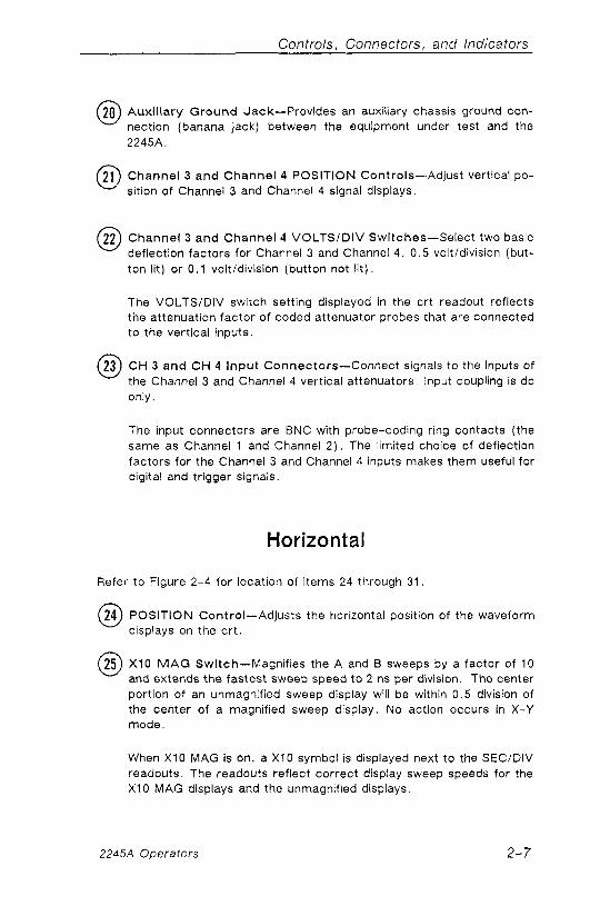
Auxi l iary G r o u n d Jack-Provides an auxiliary chassis ground con- nection (banana jack) between the equipment under test and the 2245A.
Channe l 3 a n d Channe l 4 POSITION Controls-Adjust vertical po- sition of Channel 3 and Channel 4 signal displays.
Channel 3 a n d Channel 4 VOLTSIDIV Switches-Select two basic deflection factors for Channel 3 and Channel 4, 0.5 voltldivision (but- ton lit) or 0.1 voitldivision (button not l i t ) .
The VOLTSIDIV switch setting displayed in the cr t readout reflects the attenuation factor of coded attenuator probes that are connected to the vertical inputs.
C H 3 a n d C H 4 l n p u t Connectors-Connect signals to the inputs of the Channel 3 and Channel 4 vertical attenuators, lnput coupling is dc only.
The input connectors are BNC with probe-coding ring contacts (the same as Channel 1 and Channel 2 ) . The limited choice of deflection factors for the Channel 3 and Channel 4 inputs makes them useful for digital and trigger signals.
Horizontal
Refer to Figure 2-4 for location of items 24 through 31
@ POSITION Control-Adjusts the horizontal position of the waveform displays on the c r t .
25 XlO M A G Switch-Magnifies the A and B sweeps by a factor of 10 O and extends the fastest sweep speed t o 2 ns per division The center portion of an unmagnified sweep display will be within 0 .5 division of the center of a magnified sweep display. No action occurs in X-Y mode.
When XI0 MAG is on, a X I0 symbol is displayed next to the SECIDIV readouts. The readouts reflect correct display sweep speeds for the XI0 MAG displays and the unmagnified displays.
2245A Operators

Controls. Connectors, and Indicators
HOLD: MIN SETUP
6 POSITION
F igure 2-4. Hor izonta l con t ro ls a n d ind icators .
@) M O D E B u t t o n s (Up-Ar row a n d Down-Ar row) a n d lnd ica- tors-Select the operating mode of the horizontal defiection system. Pressing the Up-/Down-Arrow buttons selects the horizontal deflec- tion mode as shown by the MODE lights. Not all Measurement modes are compatible with all horizontal deflection modes. See Table 3-1, Behavior for Horizontal MODE Changes, in Section 3.
A-Selects A sweep horizontal deflection. The A sweep speed is de- termined by the A SECIDIV switch setting as displayed in the cr t

Controls, Connectors, and Indicators
readout. Whenever A MODE is selected, the AIB SELECT switch is set to A Trigger.
ALT-Alternates between A sweep (with an intensified zone repre- senting B sweep) and B delayed sweep. Both A and B SECIDIV switch settings are displayed In the crt readout, but only the B can be adjusted. Whenever ALT MODE is selected, the AIB SELECT switch is set to B Trigger.
The B sweep speed cannot be set slower than the A sweep speed; attempting to do so forces the A sweep speed to follow the B sweep speed. To increase the A sweep speed in the ALT MODE, set the Horizontal MODE to A, adjust the SECIDIV switch to a faster A sweep setting, and reset the Horizontal MODE switch to ALT. The B sweep speed and the length of the intensified zone are determined by the B SECIDIV switch setting.
B-Selects B sweep horizontal deflection. The B sweep speed is de- termined by the B SECIDIV switch setting as displayed in the crt readout. Whenever B MODE is selected, the AIB SELECT switch is set to B Trigger.
The start of the B sweep In RUNS AFTER mode (or the arming of the B Trigger in any triggered mode) is delayed from the start of the A sweep by a time determined by the setting of the It OR DELAY con- trol. The B SECIDIV switch setting and the Delay Time Position set- ting are displayed in the crt readout. A greater-than sign (>) is dis- played in front of the Delay Time readout if the B Trigger MODE is not RUNS AFTER.
X-Y-The signal applied to CH 1 OR X input connector produces the horizontal (X-AXIS) deflection. Signals applied to any vertical input connector or ADD may be selected to provide the vertical deflection (Y-Axis) . The X-Y displays are horizontally positioned by the Horizontal POSI- TION control and vertically positioned by the associated vertical chan- nel POSITION control.
@ A A N D B SECiDlV Switch-Selects the horizontal deflection rate (sweep speed) for both the A sweep and tilt. B sweep in a 1-2-5 sequence. Calibrated sweep speeds are obtained with the A and B SECIDIV VAR control in the detent (fully clockwise) position. The A SECIDIV switch setting Is set only from the A Horizontal MODE and the B SEClDlV switch is set only from the ALT or B Horizontal MODE.

Controls, Connectors, and Indicators
NOTE
The B sweep speed can never be slower than the A sweep speed. When the two sweep speeds are the same, they are "locked." At this point A will follow 8 to slower SECIDIV settings (in ALT or 6 ) and 8 will follow A to faster settings ( in A ) .
A SECIDIV-The calibrated A sweep speed is selected only in A Hori- zontal MODE from 0.5 s per division to 20 ns per division (XI0 MAG off).
B SECIDIV-The calibrated B sweep speed is selected either in ALT or B Horizontal MODE from 5 ms per division to 20 ns per division (XI0 MAG off).
@ A and B SECIDIV VAR Control-Provides continuously variable, un- calibrated A and B sweep speeds to at least 2.5 times slower than the calibrated SECIDIV setting.
The VAR control extends the slowest A sweep speed to at least 1.25 sec per division. The UNCAL indicator is lit and a greater-than sign (>) is displayed before each SECIDIV readout value when the sweep speeds are greater than the SECIDIV settings. The SECIDIV settings are calibrated when the VAR control is in the fully clockwise (detent) position.
@ CURSORSITIME POSITION Controls-Set the reference and delta cursors on the display.
NOTE
The reference and delta cursors will only track together as long as the reference delay plus the delta delay is less than 10 times the A SECIDIV setting (10 horizontal graticule divi- sions). The cursors cannot be positioned left of the 1st or right of the 11th vertical graticule lines.
I t OR DELAY-This control has the following functions:
1. Positions the reference and delta cursors together in the CURSOR VOLTS, IITIME, or TIME measurement mode when the Horizontal MODE is A (also X-Y for CURSOR VOLTS).
2245A Operators

Controls, Connectors, and Indicators
2. Positions the reference and delta delays together in the 11TIME or TlME measurement mode when the Horizontai MODE Is ALT or A.
3 . Sets the B sweep delay time in the DELAY measurement mode when the Horizontal MODE is ALT or B.
+I -This control has the following functions:
1. Positions the delta cursor in the CURSOR VOLTS, l IT iME, or TlME measurement mode when the Horizontal MODE is A (also X-Y for CURSOR VOLTS).
2. Sets the B sweep delta delay in the 1iTIME or TlME measure- ment mode when the Horizontal MODE is ALT or B.
@) U N C A L Indicator-Lights when the A AND B SECiDlV settings are uncalibrated (variable function in effect).
@ TRACE SEP Control-Positions the B sweep trace vertically with re- spect to the A sweep trace when ALT Horizontal MODE is selected.
Trigger
Refer t o Figure 2-5 for location of items 32 through 38.
@ A I B SELECT Button-Directs the MODE, SOURCE. CPLG, SLOPE, and LEVEL controls and Trigger lights (TRIG'D and READY) t o either the A or B Trigger system (A, when lit; B, when not l i t ) .
Either A or B trigger can be selected for any Horizontal MODE; how- ever, A IB SELECT is preset to A when A Horizontal MODE is selected, and B when ALT or B Horizontal MODE is selected. No change occurs when switching from B to X-Y Horizontal MODE.
@ SLOPE Button-Selects the slope (positive- or negative-going) of the trigger source signal that triggers either the A sweep or the B sweep. (Button lit = positive-going; button not lit = negative-going.)
2245A Operators 2-1 1

Controls, Connectors, and lndica tors
TRIGGER
- - -
Figure 2-5. Trigger controls and indicators.
@ HOLDOFF Control-Varies holdoff time between the end of one A sweep and the start of the next A sweep.
The HOLDOFF control can increase the minimum holdoff time by at least 10 times. Adjusting this control can improve triggering stability of aperiodic signals (i. e. , complex digital waveforms) .
@ LEVEL Control-Sets the amplitude level on the trigger signal at which either the A or B sweep Is triggered.
Adjusting the LEVEL control to either end of its range, In the AUTO LEVEL trigger mode, resets the limits of the Trigger LEVEL control range to the peak-to-peak amplitude of the trigger source signal.
2245A Operators

Controls, Connectors, and Indicators
@ M O D E B u t t o n s (Up- a n d Down-Ar rows) a n d Indicators-Seiect the operating modes of the A and B trigger systems. Pressing the Up-/Down-Arrow buttons selects the operating modes as shown by the TRIGGER MODE lights.
Selections available for the A Trigger (A19 SELECT button lit) are: AUTO LEVEL, AUTO, NORM, TV LINE, TV FIELD, and SGL SEQ. Selections for the B Trigger (A19 SELECT button not lit) are: AUTO LEVEL, RUNS AFTER, NORM, TV LINE FROM A SOURCE.
A Trigger Modes
AUTO LEVEL-Automatically sets the range of the Trigger LEVEL control to the peak-to-peak limits of an adequate A Trigger source signal and triggers the sweep.
Autoleveiing is repeated if triggering is lost, if the TRIGGER LEVEL control is rotated to either end stop, or if AUTO LEVEL TRIGGER MODE is selected again. AUTO LEVEL mode is useful for quickly locating and maintaining an appropriate triggering level.
NOTE
When in AUTO LEVEL or AUTO triggering, the A sweep free-runs to produce a baseline trace when the A trigger source signal amplitude is too low or the frequency is below 10 H z . Switch to NORM triggering if the repetition rate is too slow for autoleveling.
AUTO-Triggers the same as the NORM Trigger MODE when an ade- quate trigger signal is applied. However, the A sweep free-runs to display a baseline trace when there is no trigger signal or the frequency is below 10 Hz. The set triggering level changes only when the TRIGGER LEVEL control is adjusted to a new level setting.
NORM-Triggers the A sweep when the A Trigger LEVEL control is set within the peak-to-peak limits of an adequate trigger signai. When the A sweep is not triggered, no baseline trace is displayed.
2245A Operators

Controls, Connectors, and Indicators
TV LINE-Starts the A sweep at the beginning of a video signal line. SLOPE polarity must match the composite sync polarity ( i .e. , f SLOPE for negative sync) to obtain TV LINE triggering on the horizon- tal sync pulse, Instruments Serial Numbered 8020100 or above can have the TV SLOPE polarity preset by changing the instrument con- figuration from the CONFIGURE menu (see "Service Menu Features" in Section 3 ) .
TV FIELD-Starts the A sweep at the beginning of a video signal field. SLOPE polarity must match the composite sync polarity to obtain TV FIELD triggering.
SGL SEQ (Single Sequence)-Sets up the A sweep for single-se- quence operation. Each additional press of the down-arrow MODE button, when in single-sequence mode, resets the sweep and makes it ready to accept a trigger. As in NORM trigger MODE, the set trig- gering level changes only when the TRIGGER LEVEL control is ad- justed to a new level setting.
When triggered, the sweep runs to produce a single sweep of each trace as required by the setting of the VERTICAL MODE and HORI- ZONTAL MODE switches. Each displayed sweep in the sequence re- quires a distinct A sweep triggering event. The READY light remains on until the final trace in the sequence is completed. The readout and cursors can be set to turn on briefly at the end of the sequence when using a camera (factory setting default mode), or they can be set to remain on by changing the instrument configuration from the CON- FIGURE menu (see "Service Menu Features" in Section 3 ) .
B Trigger Modes
AUTO LEVEL-Sets the range of the Trigger Level control to the peak-to-peak limits of an adequate B Trigger-source signal and trig- gers the B sweep.
The auto-level range is reset when triggering Is lost, TRIGGER LEVEL control is rotated to either end stop, or AUTO LEVEL Trigger MODE is reseiected. AUTO LEVEL mode is useful for quickly locating an ap- propriate triggering level.
The B sweep operates in RUNS AFTER mode when the trigger-source signal amplitude is too low or the frequency is below 10 Hz. Switch to NORM triggering if the repetition rate is too slow for auto leveling. The A Sweep must be running (free-running or triggered) for B Sweep to trigger.
2245A Operators

Controls, Connectors, and Indicators
RUNS AFTER-Starts the B sweep immediately after the delay time selected by the I t OR DELAY control.
The Trigger MODE must be in RUNS AFTER before time measure- ments can be selected when the Horizontal MODE is ALT or B. A time measurement will be canceled if the Trigger MODE is changed from RUNS AFTER while in the ALT or B Horizontai MODE.
NORM-The B sweep is triggered when an adequate trigger signal is received after the delay time condition has been met . When there is no trigger signai, there is no B sweep trace.
T V L INE F R O M A SOURCE-Starts the B sweep at the beginning of the video signal line received after the delay time has been met .
SLOPE polarity defaults to the A Trigger SLOPE. This must match the composite sync polarity t o obtain correct triggering on the horizontal sync pulse.
SOURCE (Up-Ar row a n d Down-Ar row) B u t t o n s a n d Indi- cators-Select the trigger source for either the A or the B Trigger system as directed by the A /B SELECT button. Pressing the Up-/Down-Arrow SOURCE buttons selects the trigger source (for A or B trigger system) as shown by SOURCE lights.
VERT-Selects the trigger signal f rom the displayed waveforms
The TRIGGER MODE and VERTICAL MODE switch settings determine the trigger signal source selection. When VERT is selected, one or more of the SOURCE lights will be on to indicate the trigger signal source. See Table 2-1 for VERT Trigger SOURCE selections.
C H I-The signal applied to the CH 1 OR X input connector Is the source of the trigger signal.
C H 2-The signai applied t o the CH 2 input connector is the source of the trigger signal.
C H 3-The signal applied to the CH 3 input connector is the source of the trigger signal.
2245A Operators

Controls, Connectors, and Indicators
Trigger and
Ver t ica l M o d e s
AUTO LEVEL
or CHOP
NON- AUTO LEVEL
and ALT
Table 2-1
VERT Tr igger SOURCE
A D D M o d e
Trigger Source Selected
On I Algebraic sum of CH 1 and CH 2 input signals.
Off I Lowest numbered vertical channel displayed.
CH 4-The signal applied to the CH 4 input connector is the source of the trigger signal.
On or Off
LINE-The triggering signal is obtained from a sample of the ac power-source waveform. This trigger source is useful when the dis- played waveform frequency is time related to the ac power-source frequency.
Alternates between displayed vertical channels in the following order: Ch 1 Ch 2 , Ch 3, CH 4, and ADD.
@ CPLG (Up-Arrow a n d Down-Arrow) Bu t tons and lnd ica- tors-Select the method of coupling the input trigger signal to the A or B trigger system as directed by the A/B SELECT button. Pressing the Up-/Down-Arrow buttons selects the trigger coupling as shown by the CPLG lights.
DC-Couples dc and ail frequency components of a triggering signal to the trigger circuitry.
DC coupling is useful for most signals, but it is especially useful for providing a stable display of low-frequency or low-repetition-rate signals.
NOISE REJ (No ise Reject)-Couples all frequency components of the input signal t o the trigger circuitry but increases the peak-to-peak signal amplitude required to produce a trigger event.
2245A Operators

Controls, Connectors, and lndica tors
NOISE REJ coupling is useful for improving stability when the trigger signal Is accompanied by low-level noise.
H F REJ (H igh F r e q u e n c y Reject)-Attenuates high-frequency triggering signal components above 50 kHz.
HF REJ coupling is useful for providing a stabie display of low-frequency components of complex waveforms and eliminates high-frequency interference f rom the trigger signal.
L F REJ (Low F r e q u e n c y Reject)-Attenuates low-frequency trig- gering signal components below 100 kHz and blocks the dc component of the trigger signal.
LF REJ coupling is useful for producing stable triggering on the high- frequency components of complex waveforms and rejecting low-frequency interference or power supply hum from the trigger signal.
AC-Attenuates trigger signal frequency components below 50 Hz and blocks the dc component of the signal.
AC coupling Is useful for triggering on ac waveforms that have a large dc offset.
Rear Panel
Refer to Figure 2-6 for location of items 39 through 41.
@ EXT Z-AXIS INPUT Connector-Connects external signals to the Z-Axis amplifier for intensity modulating the cr t display.
Signals applied t o the EXT Z-AXIS INPUT do not affect display waveshape. Signals with fast rise times and fall times provide the most abrupt intensity change. The active region threshold level Is 1 .8 V. Z-Axis voltage above the threshold voltage decreases the intensity, and 3.8 V or more produces noticeable modulation. The Z-Axis signals must be time-related to the displayed signal to obtain a fixed intensity-modulated c r t display.
@ Fuse Holder-Contains the primary power fuse.
2245A Operators

Controls, Connectors, and Indicators
r CAUTION TO " 1 0 0 i L E C T R C S H O C K THE P O W E R C O R D P R O T E C T I V E G R O L N D N G C O N D U C T O R M U S T BE i O N N E C T E D 10 G R O U N D
D C N O T R E M O V E C O V E R S qEFEP S E R V C N i , T O O U A L I F E D P E R S O N N E L
D I S C O N N E C T I N P U T P O W E R BEFORE REPLACING FUSE
FOR C O N T I N U E D FIRE P R O T E C T l O h REPLACE O N L Y WITH SPECIFIED TYPE A h D R A T E D FUSE
.O REMOVE POWER C O R D
OISIONNEC- PLUS AND (IOTbTt R i T A h t R CLIP 3 0
Figure 2-6. Rear panel connectors and fuse.
@ Power Cord Receptacle-Connects the ac power source to the instrument power supply.
The power cord protective-ground connection is connected to the exposed metal parts of the instrument. The power cord must be connected to a properly grounded source for electrical-shock protection.
Measurements and Auto Setup Controls
Refer to Figure 2-7 for location of items 42 through 46.
@ CLEAR MEASIMT-Clears displayed service menus and cursor measurements functions.
2245A Operators

Controls, Connectors, and indicators
MEASUREMENTS CLEAR 1
MEAS MT VOLTS T m E TIME
F igure 2-7. M e a s u r e m e n t con t ro ls .
@ CURSOR VOLTS-Turns on the cursor volts measurement mode and displays two positionabie horizontal cursors. O n e cursor is automati- cally positioned at the upper peak of the displayed waveform and the other at the lower peak. The voltage difference between the upper and lower cursors is displayed in the top line of the cr t graticule. Cur- sors can be repositioned as desired using the + control to move the upper cursor and the I t OR DELAY control to move both cursors to- gether.
The measurement channel for the cursor volts measurement mode is set to Channel 1 or Channel 2 when either is displayed alone. If both CH 1 and CH 2 are selected, the measurement channel is set to Channel 1 unless Channel 2 had been selected first.
@ 1 /TIME- urns on the 1 /TIME (frequency) measurement made and displays two positionable vertical cursors in A MODE. ALT and B . .
MODE display's have two B sweeps, and in ALT MODE the A sweep has two intensified zones. The I ITIME difference between the left and right cursors or edges of the B sweep is displayed in Hertz in the top line of the cr t graticule. The displayed value accurately represents the frequency of a repetitive input signal when the cursors or edges of the B display are positioned so that they span one complete period of the waveform.
45 TIME-Turns on the delta-time measurement mode and displays two O positionable vertical cursors in A M O D E ALT and B MODE displays have two B sweeps, and in ALT MODE the A sweep has two intensi-
2245A Operators 2-19

Controls, Connectors, and Indicators
fied zones, the delta-time difference between the left and right cur- sors or edges of the B display is dispiayed in seconds in the top line of the crt graticule.
NOTE
Measurement channels for time measurements modes in ALT or 8 Horizontal mode are set to the lowest number dis- played channel for the delay time and the next lowest num- ber dispiayed channel for the delta-delay time, if more than one channel is displayed. Both are set to the same channel when only one is displayed. ADD is considered the highest numbered channel.
@AUTO SETUP Button-Automaticaiiy sets up the front-panel con- trols to produce a usable crt display of the input signals. Setups are based on the characteristics of the applied signals. The voltage and frequency characteristics of the input signal must be within the limits of the 2245A specifications. Auto-setup action for each front-panel control is shown in Appendix A.
NOTE
MIN SETUP as described below is only available on instru- ments Serial Numbered 8020100 or above.
M I N SETUP-Pushing and holding the Auto-Setup button unitl instru- ment operation returns enters the MIN SETUP function. This sets up the front-panel controls as the Auto-Setup does but leaves many of the controls unchanged from what the user has previously set. MiN SETUP setup action for each front-panel control is shown in Appendix A.
2245A Operators

SECTION 3
OPERATORS FAMILIARIZATION
2245A Opera tors

This Document was scanned from the original Tektronix Service Manual
For enquiries about high quality technical manuals
This Document is a complete Scan from the original Tektronix manual For enquiries about our complete High quality line of technical Manuals in PDF
mailto : [email protected]

Opera tors Familiarization
BASIC OPERATION
This subsection contains the basic operating information and techniques that should be considered before attempting any measurements. For loca- tion and function of instrument controls, connectors, and indicators see "CONTROLS, CONNECTORS, AND INDICATORS" Section 2 of this manual.
Readout Display The crt readout display indicates how the instrument controls are set up. No physical markings are on the rotating switches to indicate the control setting. A key to the location and type of readout information displayed is illustrated in Figure 3-1.
Graticule
The graticule is internally marked on the crt face to provide parallax-free viewing and enable accurate measurements (see Figure 3-2). The graticule is marked with eight vertical and ten horizontal major divisions. Major divisions are further divided Into five sub-divisions of 0.2 division each, marked along the center vertical and horizontal graticule lines. Percentage marks for rise-time and fall-time measurements are marked on the left side of the graticule. Vertical deflection factors and horizontal timing are cali- brated to the graticule so that accurate measurements can be made directly from the crt.
The waveform displays are calibrated to the crt graticule markings for making quick and very accurate measurements of waveform parameters. Voltage measurements are done by counting the vertical graticule divisions and partial divisions occupied by the portion of the display being measured and then multiplying by the VOLTSIDIV setting. Time measurements using the graticule markings are done in a similar manner. Count the number of horizontal graticule divisions and partial divisions occupied by the portion of the waveform being measured and multiply by the SECIDIV setting.
To improve the accuracy of the estimate, position the display to take ad- vantage of the 0.2 division minor graticule markings on the center graticule lines. Also position one of the measurement points of the waveform as pre- cisely as possible on one of the major graticule marks to be used as a measurement reference point.
2245A Operators

Operators Familiarization
MEASUREMENT NAME AND VALUE OR ERROR MESSAGE
0 -7 0,. INvERT1-I ADD
CHI ] COUPLING
INPUT COUPLING SYMBOLS
AC= DC= ;rr.
GND= rh
L~~~~~~~ UNCAL
Figure 3-1. Readout display locations
2245A Operators

Opera tors Familiarization
1ST OR LEFT VERTICAL
GRATICULE LlNE
l l T H OR RIGHT VERTICAL
GRATICULE LlNE
/ { I
RISE AND CENTER FALL TIME HORIZONTAL
MEASUREMENT + GRATICULE PERCENTAGE LINE
MARKERS
CENTER VERTICAL
GRATICULE LlNE
F igure 3-2. Grat icu le measurement m a r k i n g s .
Connecting Input Signals
Grounding
The most reliable signal measurements are made when the 2245A and the unit under test are connected by a common reference (ground lead) in addition t o the single lead or probe. The ground lead of the probe provides the best grounding method for signal interconnection and ensures the maxi- mum amount of signal-lead shielding in the probe cable. A separate ground lead (with a banana plug) can also be connected from the unit under test to the 2245A ground jack on the front panel.

O ~ e r a tors Familiarization
Probes
A probe provides the most convenient way t o connect an input signal t o the oscilloscope. The standard 10X probes supplied with the 2245A are shielded against electromagnetic interference and have a high input impedance for low circuit loading. The subminiature probe bodies are designed for probing circuitry with closely spaced leads.
SCALE FACTOR SWITCHING. The VOLTS/DIV scale factors, displayed on the cr t , reflect the probe attenuation factor when Tektronix coded probes are used.
OPERATING CONSIDERATIONS. To get the best waveform fidelity, keep probe ground and signal leads as short as possible.
Misadjusted probe compensation can cause measurement error. Check and adjust probe compensation whenever a probe is moved to a different channel or oscilloscope. For the probe compensation adjustment proce- dure, see Section 4 uOperator Checks And Adjustments".
For detailed operating considerations and probe maintenance, see the in- struction sheet supplied with the probe.
Coaxial Cables
Signal input cables can greatly affect the accuracy of a displayed waveform. To maintain original frequency characteristics of the input sig- nal, use only high-quality, low-loss coaxial cables. Coaxial cables must be terminated at both ends in their characteristic impedance to prevent signal reflections within the cable. Use suitable impedance-matching devices.
External Triggering
Any of the four vertical channels in the 2245A can be used as a source of A and B trigger signals. When you need a trigger signal source different from the one derived from displayed signals, you can use any free vertical input channel. CH 1 and CH 2 can "condition" a wide range of signals to produce triggers over the full vertical deflection range from millivolts to hundreds of volts. CH 3 and CH 4 have two basic attenuation factors (0 .1 and 0.5 volts/ division), making them especially useful for triggering on and viewing digital signal levels.
2245A Operators

O~era to r s Familiarization
Auto Setup
Pressing the AUTO SETUP button automatically sets up the front-panel controls based on the characteristics of the applied signal. The voltage am- plitude, sweep settings, trigger parameters, vertical and horizontal posi- tioning, and trace intensities are preset to produce a usable waveform dis- play. The waveform is horizontally centered and vertically positioned within the cr t display. The voltage and frequency characteristics of the input sig- nal must be within the limits of the 2245A specifications given in Section 6 .
Auto-setup action for each front-panel control is shown in Appendix A .
MIN SETUP MIN SETUP is only available on instruments Serial Num- bered 8020100 or above.
Pressing and holding the Auto-Setup button until the Instrument returns to normal operation initiates the MIN SETUP function. This automatically sets up the front-panel controls but leaves many of the controls unchanged from what the user has set.
MiN SETUP action for each front-panel control is whown in Appendix A .
MEASUREMENT SYSTEM
The 2245A has a highly accurate voltage- and time- measurement system. Voltage or time is measured between two cursors (or intensified zones for time measurements in the ALT or B Horizontal MODE) that can be posi- tioned, as desired, t o two points on the waveform.
Cursor Volts Measurements
Press CURSOR VOLTS to display the voltage measurement cursors and activate the voltage measurement system. The measured value is dis- played at the top of the screen.
NOTE
Changing the Horizontal MODE will remove the volts cur- sors f rom the display. Set Horizontal MODE back to A or X-Y and press the CURSOR VOLTS button to redisplay the cursors.
2245A Operators

Operators Familiarization
The voltage measurement system measures the equivalent voltage differ- ence between two horizontal cursors when the Horizontal MODE Is in A or X-Y. Both cursors are positioned by the I t OR DELAY control and the delta cursor is positioned by the + control. When the cursor volts measure- ment is first turned on, the peak voltages of the source channel signal are measured, and one cursor is placed at the most positive peak and the other is placed at the most negative peak.
The CLEAR MEAS'MT button turns off the measurement.
Time Measurements
Press the TIME button to display the time measurement cursors. The se- lected measurement type and value are dispiayed at the top of the screen.
NOTE
Changing the Horizontal MODE from B to X-Y will cancel a time measurement mode. Set Horizontal MODE back to A , ALT, or B and press the TlME or 1 ITIME button to reacti- vate the time measurement mode.
Vertical cursors are dlspiayed for use in setting the time-measurement points In A Horizontal MODE. In ALT Horizontal MODE, the delay measure- ment Is made using either the intensified zones as the measurement points or the alternate B delayed sweeps. For B Delayed Horizontal MODE, the delayed sweeps only are available for making timing measurements.
When the Horizontal MODE is either ALT or B, the B Trigger MODE must be set to RUNS AFTER (if not, the following message will be displayed: "USE RUNS-AFTER-DELAY TRIG MODE"). If the B Trigger MODE is switched away from RUNS AFTER using the front panel Trigger MODE buttons, the selected TlME or 1 /TIME measurement will be canceled. Pressing the TlME or 1 /TIME button again will reactivate the measurement only if the B Trigger MODE is set to RUNS AFTER.
In the A Horizontal MODE, cursors are used to make the time measure- ments; in ALT or B Horizontal MODE, the timing measurements are made using either the intensified zones that appear in the A sweep trace in ALT Horizontal MODE or the B delayed waveforms in either ALT or B Horizontal MODE. The I t OR DELAY control positions both cursors or delay times (reference and delta) together, and the 4 control positions the independ- ent delta cursor or delay when TlME or 1ITIME measurements are se- lected.

Operators Familiarization
TIME-Press t o measure the equivalent time difference between the two vertical cursors displayed in the A Horizontal MODE or the two time delays in ALT or B Horizontal mode. The measured time difference between the two cursors or delays is displayed in the cr t readout.
if the Horizontal MODE is X-Y, pressing the TlME button causes the mes- sage "USE A OR ALT OR B MODE" t o be displayed for two seconds. Changing the Horizontal MODE to X-Y after TlME has been activated, will cancel the measurement with no message.
1ITIME-Measures the time difference in frequency units (hertz) between the cursor positions In A Horizontal MODE or between the delay-time set- ting and the delta-delay time setting in either ALT or B Horizontal MODE. Measurement points are the left ends of the two intensified zones in ALT Horizontal MODE.
Behavior for Horizontal Mode Changes
If the Horizontal MODE is changed to a mode that cannot be used for the active measurement, that measurement will be canceled without a mes- sage being displayed. Returning to a mode that may be used and pressing the measurement button will restore the canceled measurement mode. See Table 3-1 for compatible and incompatible modes.
Table 3-1
Behav io r for Hor izonta l MODE Changes
Measurement Mode
TIME and l /TIME / A , A L T . B I X-Y I CURSOR VOLTS
2245A Operators
I Compatible Horizontal Modes
Incompatible Horizontal Modes
I I I A, X-Y ALT, B

Operators Familiarization
Measurement Compatibility and Error Messages
CURSORS VOLTS measurements cannot occur when the VOLTSIDIV VAR control for the channel being measured is not in the detent position. The displayed error message is "MEAS SOURCE VAR OUT OF DETENT."
TIME and 1ITiME measurements cannot occur when the SECIDIV VAR control is out of the detent position. The displayed error message is "VAR SECSIDIV OUT OF DETENT."
When in ALT or B Horizontal MODE, and the B Trigger MODE is not RUNS AFTER, a greater then symbol (>) will appear before the delay-time readout. The readout value displayed is the delay time between the A trig- ger and the time a B trigger can be accepted by the trigger system. A question mark ( ? ) will appear in front of the delay time readout for delay measurements when the DELAY time is set to 0 . 2 5 division or less from the beginning of the sweep.
If a time measurement is selected when in ALT or B Horizontal MODE and the B Trigger MODE is NOT RUNS AFTER, the displayed error message is "USE RUNS-AFTER-DELAY TRIG MODE. "
Measurements in Single Sequence Mode
All cursor measurements run continuously during SGL SEQ Trigger MODE. The readout and/or cursors are displayed briefly during single sequence mode for making a photographic record (or they may be configured to re- main on-see the discussion on Configure Menu in the "SERVICE MENU FEATURES" part of this section.) The displayed readout is the value of the measurement at the instant it is displayed.
B Trigger AUTO LEVEL acquisitions do not occur when the A Trigger MODE is SGL SEQ.
2245A Operators

Opera tors Familiarization
Service Menu Features
Most of the items in the SERViCE MENU are for diagnostics, troubleshoot- ing, and calibration. However, there are three menu selections that are also for operational use: CONFIGURE, SELF CAL MEASUREMENTS, and MAKE FACTORY SETTINGS. Press the CH 1 and CHOPIALT Vertical MODE buttons at the same time to display the SERVICE MENU. as shown in Figure 3-3. Menu selections are made using VERTICAL MODE buttons that correspond to the menu prompts appearing at the right side of the cr t dis-
play.
A menu-selection underline appears under the SERVICE MENU heading. Pressing the ADD button (down arrow) moves the underline down; the CH 1 button (up arrow) moves the underline up.
Once the desired item is underlined, select RUN (CH 2 button) to start the selected process. Select Quit (CH 4 button) to exit the SERViCE MENU and return to the normal oscilloscope operation
IERV?!?E. MENU/ DIAGNOSE T MENU
CONFIGURE J.
SELF CAL MEASUREMENTS
INTERNAL SETTINGS MENU/
EXERCISER MENU/ QUIT
- (CH 1)
- (ADD)
- (CH 4)
6558-12
Figure 3-3. Serv ice Menu .
2245A Operators

Operators Familiarization
Configure Menu
The CONFIGURE item allows you to select whether or not to keep the readout on in the single-sequence trigger mode.
Select CONFIGURE f rom the SERVICE MENU and answer YES or NO to each of the displayed questions. Either YES or NO will be underlined to indl- cate how the instrument is presently configured. After YES or NO is se- lected, the next configuration choice is displayed. After answering the last question, the SERVICE MENU display returns. To exit f rom the CONFIG- URE menu without answering the remaining question(s), press the END button or the CLEAR DISPLAY button. The CONFIGURE items are listed as foiiows:
NOTE
Instruments Serial Numbered 8020099 or below only have one menu item in CONFIGURE: KEEP MENU ON WHEN MEAS'MT SELECTED?
KEEP MENU O N WHEN MEAS'MT SELECTED? (Factory Settings de- fault Is NO.) Selecting NO clears the measurement menu Items f rom the display after a measurement function is selected. Measurement cursors remain displayed. The AUTO TRACKING MENU remains on after a selec- tion has been made.
Selecting YES allows a measurement menu t o remain displayed after a function is selected. The measurement menu items can be removed at any time by pressing the CLEAR DISPLAY button once.
PRESET TV TRIG SLOPE FOR -SYNC? (Factory Settings default is YES.) Selecting YES will cause the trigger slopes to preset to '-" when TV trig mode is selected, and the configure menu is exited. If NO Is selected, a second question is presented.
PRESET TV TRIG SLOPE FOR +SYNC? (Factory Settings default is NO. ) Selecting YES will cause the trigger slopes to preset to "+" when TV trig mode is selected, and the configure menu is exited. If NO is selected, the scope will not use a preset slope when a TV trig mode is selected.
2245A Operators

Operators Familiarization
6558-13
F lgure 3 - 4 . Conf igure M e n u .
CONFIGURE
END
KEEP READOUT ON IN SGL SEQ?
YES
NO . . . . RUNNING
After YES or NO Is selected, the SERVICE MENU/ display returns. Select INTERNAL SETTINGS MENU to continue with the testing or select QUIT to return to normal oscilloscope operating mode.
-c- (CH 1)
4+ (CH 4)
-t- (CHOP/ALT)
Self Cal Measurements
This selection does a self-characterization of the vertical channels 1 and 2 , and the horizontal timing. The SELF CAL MEASUREMENTS routine stores calibration constants that set the accuracy of the internal measurement system.
NOTE
SELF CAL MEASUREMENTS can be performed anytime af- ter a 20-minute warmup time to ensure the accuracy stated in Section 6 .
2245A Operators 3-1 1

Opera tors Familiariza fion
Internal Settings Menu
The INTERNAL SETTINGS MENU (see Figure 3-5) consists of MAKE FAC- TORY SETTINGS and ADJUST VERTICAL OUTPUT. MAKE FACTORY SETTINGS can be performed by the operator; ADJUST VERTICAL OUT- PUT is for use by servicing personnel. To return to SERViCE MENU, set the up-arrow key to underline INTERNAL SETTINGS MENU and press the but- ton again to display the SERVICE MENU. To return to the oscilloscope mode, select QUIT from the INTERNAL SETTINGS MENU or SERVICE MENU, or press the CLEAR MEAS'MT button.
INTERNAL SETTINGS MENU/ ........................................... MAKE FACTORY SETTINGS t MENU
ADJUST VERTICAL OUTPUT J
Q U I T
- (CH 1)
- (ADD)
- (CH 4)
F igure 3-5. In ternal Se t t ings M e n u .
MAKE FACTORY SETTINGS. Sets the front-panel controls and menu con- figurations as described in Appendix B.
2245A Operators

SECTION 4
OPERATOR CHECKS AND
ADJUSTMENTS
2245A Opera tors

This Document was scanned from the original Tektronix Service Manual
For enquiries about high quality technical manuals
This Document is a complete Scan from the original Tektronix manual For enquiries about our complete High quality line of technical Manuals in PDF
mailto : [email protected]

Operafor Checks and Adjustmenfs
Introduction
The checks and adjustments in this section are for the operator and involve using only controls and adjustments on the outside of the instrument. In- ternal adjustments must be made by a qualified service person.
Before operating the instrument for the first time and before connecting the power, refer to Section 1 "Preparation for Use" to prepare the instrument for the initial startup.
Verify that the POWER switch is OFF (out position). Plug the power cord into a power-source outlet that supplies a voltage within the operating range of the instrument's power supply.
NOTE
If you notice an improper indication or instrument mal- function during these procedures, refer the instrument to a qualified service person.
Initial Setup
The following procedure may be used to set up front-panel controls when the instrument is first turned on or when a signal is not being applied to the input connectors.
1. Press in the POWER switch button (ON) and let the instrument warm up (20 minutes is recommended for maximum accuracy).
2. Set the Instrument front-panel controls to obtain a baseline trace:
Vert ical Controls
VERTICAL MODE CH 1 POSITION Center the trace VOLTSIDIV 1 V VOLTS/DIV VAR Calibrated detent Channel 1 COUPLING GND

Operator Checks and Adjustments
Horizontal Controls
MODE POSITION Xi0 MAG A SECIDIV SECIDIV VAR
Trigger Controls
HOLDOFF A/B SELECT MODE SOURCE CPLG
Display
A INTEN FOCUS READOUT SCALE ILLUM
Measurement Functions
CLEAR MEAS'MT
A Center the trace Off 0.1 ms Calibrated detent
MIN A AUTO LEVEL VERT DC
Desired brightness Best trace definition Desired brightness Desired brightness
Press to remove any displayed cursors
Auto Setup Function
The Auto Setup function can be used to automatically set up the front- panel controls to produce a usable display of the applied signal.
1. Connect signal(s) to be displayed to the appropriate input connector(s) .
For triggering to be set up properly when the AUTO SETUP button is pressed, connect the trigger-source signal to the lowest numbered channel that will be turned on.
2245A Operators

Ooerator Checks and Adiustments
2 . Set:
VERTICAL MODE As desired (see NOTE)
Horizontal MODE As desired
3. Press the AUTO SETUP button.
NOTE
Normally, the Auto Setup of the display is sufficient for measurement purposes. If further waveform enhancement is needed, use the appropriate front-panel controls to adjust the display. For auto-setup action, see Appendix A.
Trace Rotation Adjustment
1 . Perform the "Initial Setup" procedure. Position the trace vertically to align it with the center horizontal graticule line and check that the trace is parallel with the graticule line.
NOTE
Normally, the trace will be parallel to the center horizontal graticule line, and the TRACE ROTATION adjustment will not be needed.
2 . If necessary, adjust the TRACE ROTATION to make the baseline trace parallel to the center horizontal graticule line. Use a small straight-blade screwdriver or alignment tool.
Probe Low-Frequency Compensation
Misadjustment of probe compensation is a possible source of measurement error. The attenuator probes are equipped with compensation adjustments. To ensure the best measurement accuracy, always check probe compen- sation before making measurements.
1. Connect the two supplied 10X probes to the CH 1 and CH 2 BNC input connectors.
2245A Operators
O~erator Checks and Adiustments
2 . Connect the probe tips to the PROBE ADJUST connector and the probe ground leads t o scope ground.
3. Set:
VERTICAL MODE CH 1
Horizontal MODE A
4. Press AUTO SETUP button.
5 . Set the CH 1 VOLTSIDIV setting to 0.1 V (10 mV with probe discon- nected) and vertically center the PROBE ADJUST square-wave signal.
6 . Check the square-wave signal for overshoot and rolloff (see Figure 4-1 ) . If necessary, use the special adjustment tool supplied in the probe accessory package t o adjust the low-frequency compensation for a square front corner on the square wave displayed.
7 . Press the CH 2 VERTICAL MODE button to turn CH 2 on in the display, and press the CH 1 Mode button to remove the CH 1 trace from the display.
8 . Set the CH 2 VOLTSIDIV setting to 0.1 V (10 m V with probe discon- nected) and vertically center the PROBE ADJUST square-wave signal.
9. Repeat Step 6 for the second probe on the CH 2 BNC input connector.
NOTE
Refer to the instruction manual supplied with the probe for more detailed information about the probes and adjustment procedure.
2245A Operators

Operator Checks and Adjustments
CORRECT
I00 (FLAT)
OVER COMPENSATED (OVERSHOOT)
Figure 4-1. Probe compensation.
I 10 *
I 0
- L-
Vertical Deflection Check
The PROBE ADJUST square-wave signal may be used to check the Channel 1 and Channel 2 vertical deflection system in the following procedure:
r-
1. Connect the two 10X probes (supplied) to the CH 1 and CH 2 input con- nectors.
2 . Connect both probe hook tips to the PROBE ADJUST connector.
L-
3. Set:
UNDER COMPENSATED (ROLLOFF)
VERTICAL MODE CH 1
Horizontal MODE A
4. Press AUTO SETUP button.
5 . Set CH 1 and CH 2 VOLTS/DIV switches to 0.1 V for the attached 10X probes.
2245A Operators

Operator Checks and Adjustments
6. Set the bottom of the trace of the PROBE ADJUST square-wave signal to a convenient horizontal graticule line with the Vertical POSITION control.
7. Check for a five-division display of the PROBE ADJUST square-wave signal.
8. Select CH 2 VERTICAL MODE and repeat steps 6 and 7.
9 Disconnect the probes from the instrument.
Timing Checks
The time measurement cursors may be used to check the horizontal deflec- tion system.
1. Preset instrument controls and obtain a baseline trace and set the A SECIDIV switch t o 0.1 ms. Vertically center the baseline trace.
2 . Press the TIME button t o select the Time Measurement function for measuring time difference.
3. Align the reference cursor to the second vertical graticule line using the I+ OR DELAY control (both cursors are positioned together).
4 . Adjust the + control for a reading of 800.0 p s
5 . Check that the cursors are eight divisions apart.
6 . Press the CLEAR MEAS'MT button to remove the cursors from the display.
2245A Operators

SECTION 3
BASIC APPLICATIONS
2245A Operators

This Document was scanned from the original Tektronix Service Manual
For enquiries about high quality technical manuals
This Document is a complete Scan from the original Tektronix manual For enquiries about our complete High quality line of technical Manuals in PDF
mailto : [email protected]

Basic Applications
Introduction
The TEKTRONIX 2245A Oscilloscope has a cursor measurement system for making accurate, direct-readout voltage, time, and frequency measurements. The measurements given in this section are examples of typical applications using this measurement system. After becoming familiar with the controls, indicators, and capabilities of the instrument, you can develop convenient methods for making special measurements for your own applications. A brief description of how the graticule markings are used in making measurements is given in Section 3 of this manual.
When a procedure calls for "Initial Setup" or "Auto Setup Function," refer to the "OPERATOR CHECKS AND ADJUSTMENTS" Section 4. Certain signals such as video or aperiodic (non-repeating) signals and signals con- taining many unrelated frequency components may require more adjustment of the triggering controls to obtain the best display.
Voltage Measurement Cursors
The CURSOR VOLTS function can accurately measure signals displayed on CH 1 or CH 2 . Voltage measurements using the cursors may also be done on CH 3, CH 4, and ADD waveforms by setting the VOLTSIDIV switch set- ting of the selected measurement channel to the same scale factor as the signal to be measured. However, measurements on CH 3 or CH 4 input signals will be less accurate than on the CH 1 or CH 2 input signals. Volts cursors are available for making measurements in the both the A and X-Y horizontal modes.
Voltage Difference
Use the following procedure steps as a guideline in making voltage- difference measurements using the positionable voltage cursors.
1. Apply the signal to the CH 1 input connector.
2. Set:
Vertical MODE CH 1
Horizontal MODE A
3. Press AUTO SETUP button.
2245A Operators

Basic Applications
4. Adjust the CH 1 VOLTSIDIV control so that the signal fills as much of the screen as possible.
5. Press the CURSOR VOLTS button to display the voltage cursors. The voltage cursors are initialized to the peak-to-peak voltage levels of CH 1. (See Figure 5-1)
NOTE
Voltage cursors are initialized to levels seen by the peak detector circuitry. Noise and other signals riding on the sig- nal to be measured will cause a slight displacement of the cursors from the displayed waveform peaks, and above 50 MHz the bandwidth rolloff of the trigger circuit will affect the initial cursor positions on the waveform.
VOLTAGE DIFFERENCE
Figure 5-1. Voltage difference measurement using cursors.
5-2 2245A Operators

Basic Applications
6. For a peak-to-peak voltage measurement, slightly reposition the cur- sors as necessary to precisely align them with the peaks of the waveform. The I t OR DELAY control positions both cursors together (keeping the original difference between cursors), and the 4 control positions the Independent cursor. Read the measurement value dis- played in the top line of the readout.
7 . To make voltage difference measurements between any other locations on the waveform, move the I t cursor to the more-negative point of interest, then position the independent + cursor to the more positive point on the waveform. Read the voltage difference.
Time Measurement Cursors
Time measurement cursors may be used on any of the input waveforms only in the A Horizontal MODE. (Time measurements are also available in ALT and 6 Horizontal MODE; see "Time Delay Measurement" in this section. )
Time Difference
Use the following procedure steps as a guideline in making time difference measurements using the TIME cursors. As with the voltage cursors, the It OR DELAY control positions both cursors together, and the + control positions the independent (delta-time) cursor.
1. Apply the signal to the input connector(s)
NOTE
Make sure that the signal used as the trigger source is con- nected to the lowest numbered channel that will be turned on.
2245A Operators

Basic A ~ ~ l i c a t i o n s
2 . Set:
Vertical MODE As desired
Horizontal MODE A
3 . Press AUTO SETUP button
4 . Adjust the VOLTSlDlV control so that the measurement points can be easily seen.
5. Select a SECIDIV setting that provides the fewest number of cycles of the applied waveform necessary to display the measurement points of interest. This is to improve the accuracy of cursor placement for the measurement.
6 . Press the TlME button to display the time cursors.
NOTE
The independent cursor (+I ) cannot be positioned in front of the reference cursor (It OR DELAY).
7 . Use the I t OR DELAY control to position the reference cursor to the leftmost point on the waveform to be measured. Use the 4 control to position the independent cursor to the rightmost point to be measured. Then, read the time difference value In the top line of crt readout.
Period Measurement
This is a time-difference measurement. Position the TlME cursors to define a full period (1 cycle) of the input waveform. Its value is displayed. Use the setup for making time-difference measurements as a guideline for making period measurements (see Figure 5-2).
2245A Operators

Basic Applications
PERIOD 1
Figure 5-2. Period measurement.
Frequency Measurement
A frequency measurement is made using the same method as a period measurement; the difference is that the l/TIME measurement mode is selected instead of TIME. The measurement value is displayed in frequency units. When the full period is defined by positioning the cursors, the fre- quency of the signal is displayed. Use the same front panel setup used for time-difference measurement as a guideline for making a frequency measurement with cursors (see Figure 5-3).
2245A Operators

Basic Applications
FREQUENCY
Figure 5-3. Frequency measurement.
Rise-Time Measurements
Making rise-time or fall-time measurements requires some additional signal scaling to use the graticule rise-time measurement aids. Numbers 0%, 10, 90, and 100 are etched near the left vertical graticule line. These numbers provide convenient reference points for making rise- and fall-time measure- ments when the signal to be measured Is properly set up. Use the following steps as a guideline In making rise-time measurements.
1. Apply the signal to the CH 1 Input connector
2 . Set:
Vertical MODE CH 1
Horizontal MODE A
A Trigger SLOPE f
2245A Operators

Basic A ~ ~ l i c a t i o n ~
3. Press AUTO SETUP button.
4. Set the CH 1 VOLTSIDIV and VOLTSIDIV VAR controls to provide an exact five-division vertical display.
5. Use the CH 1 Vertical POSITION control t o place the negative amplitude of the signal on the 0 % reference line and the positive amplitude on the 100% reference line.
6. lncrease the SEClDlV setting to stretch out the rising edge of the waveform as much as possible t o improve the cursor placement accuracy (see Figure 5-4) .
7. Adjust the Trigger LEVEL control, if necessary, to get the 10% level on screen.
NOTE
If measuring fall t ime, use negative SLOPE. This places the trigger point at the beginning of the sweep so that when the SEClDlV setting is advanced, the slope of interest remains within the viewing area.
8. lncrease the A INTEN control if necessary to brighten the beginning of the trace, and use the Horizontal POSITION control to place the 50% level (center) of the rising edge of the waveform at the center vertical graticule line.
9. Press TIME button t o display the time cursors.
10. Use the I t OR DELAY control to align the first cursor to the rising edge at the point where it crosses the 10% reference graticule line. Then use the + control to align the second cursor to the point where the rising edge crosses the 90% graticule line and read the rise time displayed in the top line of the cr t readout (see Figure 5-4).
2245A Operators

Basic A ~ ~ l i c a t i o n s
RISE TIME
Figure 5-4. Rise-time measurement.
Phase Measurements
Making a phase measurement is done by first setting a reference for the full 360 degree waveform period. Use the following procedure as a guide:
1. Apply the reference waveform to the CH 1 input connector (any channel may be used, but CH 1 and CH 2 provide the most signal scaling possi- bilities). Use the standard 10X attenuator probe supplied with the instru- ment to make the signal connections as they produce very little signal loading to a circuit under test and produce matched delays. For phase measurements, external loading of a circuit and different delays in the signal connection paths will produce incorrect results.
2245A Operators

Basic Applications
2 . Select CH 1 for display using the Vertical MODE buttons, and set the Input COUPLING for CH 1 and CH 2 to DC. AC may be used if the signals t o be measured are riding on a dc voltage, but set both inputs to the same coupling. AC coupling produces some signal phase shift, es- pecially at lower frequencies.
3 . Set the CH 1 VOLTSIDIV control to display the reference waveform with about five divisions of amplitude. Vertically center the waveform.
4 . Set the A SECIDIV setting (in A Horizontal MODE) to display at least one complete reference waveform period and no more than two (if pos- sible). An excessive number of cycles of the reference waveform In the display reduces the ability to make an accurate reference setting.
5. Select f or 1 SLOPE to position the waveform correctly within the graticule area for ease in measurement when viewing a single cycle of the reference signal.
6 . Press the TIME button t o display time cursors.
7. Position the first vertical cursor to the point where the reference waveform crosses the center horizontal graticule line in the positive di- rection (see Figure 5-5A). The Horizontal POSITION control may be used as necessary t o center the waveform period in the viewing area.
8. Position the delta cursor t o the second positive crossing of the center horizontal graticule line by the reference waveform as shown in Figure 5-5A.
9 . Note the time readout at the top of the graticule. This is the 360° re fe rence t ime.
10. Apply the phase-shifted, sine-wave signal to be measured to the CH 2 input connector using a 10X probe, and turn CH 2 Vertical MODE on to display the signal.
2245A Operators

Basic Applications
Figure 5-5. Phase difference measurement.
2245A Operators

Basic Applications
11. Set the VOLTSIDIV and VOLTSIDIV VAR controls to match the ampli- tude of the phase-shifted signal to that of the reference waveform as shown in Figure 5-56. Use the Vertical POSiTlON control as necessary to align the two waveforms vertically.
12. Position the cursors to a positive or negative crossing of each signal as shown in Figure 5-5B.
NOTE
Figure 5-56 shows the delta time measurement made from the second positive crossing of each waveform. The delta time could also be measured from the first positive crossing (near the left edge of the screen), or the first negative crossing (near center screen).
Read the delta t ime at the top of the graticule and calculate the phase difference from the formula:
delta t ime 360 Phase Difference (in degrees) =
reference t ime
or, as in Figure 5-5, - 20.97ns ~ 3 6 0 0 = 22.50 336 ns
NOTE
For increased resolution of the phase measurement, the sweep may be increased and both cursors repositioned to the measurement points (see Figure 5-5CJ. The X I 0 MAG feature may also be used in a similar manner by placing the measurement points at the center vertical graticule line be- fore pressing the X I 0 MAG button (you may want to reduce the A SECIDIV setting prior to turning on the X I 0 MAG).
Time Delay Measurement
When using ALT Horizontal Mode, the TIME measurement mode provides two intensified zones on the A trace. There are also two B delayed traces matching each intensified zone. A direct readout of the delay difference between the two zones is displayed in the top line of crt readout. Use the following procedure steps as a guideline for making delta-time delay-time measurements.
2245A Operators

Basic Amlications
1. Apply the signal or signals that measurements are to be made on to the vertical input connector(s) . When making delay measurements between two different channels always connect the reference signai to the lower numbered channel and the delta signal to the higher numbered active channel. Turn on the Vertical MODE channels needed to display the sig- nals.
2 . Set A Trigger MODE to AUTOLEVEL, B Trigger MODE to RUNS AFTER, and A Trigger SOURCE to VERT.
3. Use a VOLTSIDIV setting that produces a usable vertical display ampii- tude for viewing ease; use an A SEClDlV setting that produces two to five repetitions or cycles of the signai across the graticuie area.
NOTE
When viewing multiple traces, it is best to limit the vertical amplitude to about two divisions so that good trace sepa- ration may be obtained in the display.
4 . Switch the Horizontal MODE to ALT. Advance the SEClDlV setting at least one position to obtain a faster B SEClDlV setting.
5 . Press the TlME button to turn on the time-delay measurement mode which displays two intensified zones on the A Sweep trace and two aiter- nate B Delay Sweeps. Use the TRACE SEP and Vertical POSiTiON con- trols to position the sweeps vertically in the graticuie area for ease of viewing the separate traces.
NOTE
When the TlME button is pushed, the delay-time measure- ment channel is automatically set to the lowest numbered active channel and the delta-time measurement channel is set to the next lowest numbered active channel. If one of the measurement channels is turned off when the time- delay measurement mode is active, both intensified zones will be displayed on the other measurement channel. Both intensified zones must be displayed on the same channel for making period, pulse width, or rise-time and fall-time measurements. If only a single channel is selected for dis- play, both delays will default to that channel.
2245A Operators

Basic Applications
6. Using the center vertical graticuie line as a reference point, set the ref- erence deiay to aiign the B Sweep display of the first point of interest to be measured to that reference point with the It OR DELAY controi. Set the time deiay to align the B Sweep dispiay of the second point of interest to the reference point using the +i controi. The time difference between the two B Sweep delays is displayed at the top of the screen.
Once the measurement points are identified, the A intensified Sweep traces may be removed from the dispiay for ease in viewing the B Sweep traces by switching to B Delayed Horizontal MODE. in B Horizontal MODE, exact placement of the two delays may be obtained by positioning one trace over the other and then aligning the measurement point using the + control. Additional resolution may be obtained by advancing the B SECIDIV switch setting to further expand the B Sweep traces.
FIRST POINT OF INTEREST TIME DIFFERENCE
SECOND POINT OF INTEREST
\ REFERENCE GRATICULE LINE
6558-21
Figure 5-6. Time difference between two delays.
2245A Operators

Basic Applications
Add Mode
With the Vertical MODE set to ADD, the resulting waveform is the algebraic sum of the signals appiied to the Channel 1 and Channel 2 inputs (CH 1 t CH 2) . A plus symbol (t) appears in the readout between the CH 1 and CH 2 VOLTSIDIV setting readout to indicate that ADD is active. If the CH 2 INVERT feature Is turned on (INVERT button light on), the waveform dis- played is the difference between the signals applied to the Channel 1 and Channel 2 inputs. Neither CH 1 nor CH 2 waveform needs to be displayed to obtain the ADD trace, but any or ALL vertical input channels may be dis- played at the same time if desired.
When CH 1 and CH 2 VOLTSIDIV switches are set to the same setting, the total defiection factor in the ADD mode is equal to the defiection factor indicated by either VOLTSIDIV readout. The voitage cursors may be used to make voitage measurements on the ADD trace if either CH 1 or CH 2 is dispiayed along with the ADD trace (CH 1 and CH 2 must be at the same VOLTSIDIV setting). If any voltage measurement function is active, turning off CH 1 and CH 2 to display the ADD trace by itself causes the message "VOLTMETER SOURCE: CH 1 OR 2 ONLY" to appear and cancels the measurement. if calling for a voltage measurement with ADD displayed and neither CH 1 nor CH 2 displayed, the CH 1 Vertical MODE is turned on, and the measurement is initialized to the signal appiied to the CH 1 input.
Two common uses for ADD mode are: (1) providing a dc offset to bring an ac signal riding on top of a large dc voltage within the graticuie viewing area and (2) canceling out a large line-frequency signal component to view some small feature riding on the waveform in greater detail using common-mode rejection.
The following general precautions should be observed when using ADD mode.
a. Do not exceed the input-voltage rating of the oscilloscope or probe.
b. Do not apply signals that exceed the equivalent of about eight times the VOLTSIDIV switch settings, since large voltages may distort the dis- play. For example, with a VOLTSIDIV setting of 0.5 V, the voltage ap- plied to that channel should not exceed 4 V.
c. Use CH 1 and CH 2 POSlTiON control settings which most nearly position the signal on each channel to mid-screen when viewed sepa- rateiy.This ensures the greatest dynamic range for ADD mode signal displays.
2245A Operators

Basic Amlications
d. To have similar responses for both channels, use the same input COUPLING for both CH 1 and CH 2.
The following procedure shows how to eliminate an unwanted ac input- power frequency signal component from the displayed signal.
a. Perform the "Initial Setup" in "OPERATOR CHECKS AND ADJUST- MENTS" Section 4 , but do not apply any signals and center the baseline trace vertically.
Apply the signal of interest containing the unwanted line-frequency component to the CH 1 input connector.
Apply a line-frequency signal to the CH 2 input connector. To maximize cancellation, the signal applied to the CH 2 input must be in phase with the frequency component to be canceled from the CH 1 signal.
Select CH 1 and CH 2 Vertical MODE
Set Trigger SOURCE switch to VERT.
Set both VOLTSIDIV switches to produce displays of about two or three divisions in amplitude.
Adjust the CH 2 VOLTSIDIV switch and VAR control so that the CH 2 display is about the same amplitude as the component to be canceled in the CH 1 waveform (see Figure 5-7A).
Select both ADD and CH 2 INVERT. Turn off the CH 1 and CH 2 dis- plays and slightly readjust the CH 2 VOLTSIDIV VAR control for maxi- mum cancellation of the line-frequency component (see Figure 5-78) ,
The SEC/DiV setting may be set to a faster sweep speed to expand the waveform and the display amplitude may be increased by advancing both VOLTSIDIV switches and readjusting the VOLTS/DIV VAR con- trols as necessary to maintain cancellation of the undesired signal component.
2245A Operators

Basic Applications
CH 1 SIGNAL WITH UNWANTED LlNE FREQUENCY
COMPONENT
CH 2 SIGNAL FROM LlNE
FREQUENCY SOURCE
(INVERTED)
SIGNAL WITH LlNE FREQUENCY
COMPONENT CANCELED
(A) CH 1 AND CH 2 SIGNALS.
(B) RESULTANT SIGNAL.
6558-22
Figure 5-7. Eliminating common-mode signals.
2245A Operators

PERFORMANCE CHARACTERISTICS
2245A Operators

This Document was scanned from the original Tektronix Service Manual
For enquiries about high quality technical manuals
This Document is a complete Scan from the original Tektronix manual For enquiries about our complete High quality line of technical Manuals in PDF
mailto : [email protected]

Performance Characteristics
Introduction
Electrical characteristics in Table 6-1 apply when the 2245A has been cali- brated at an ambient temperature between +20°C and +30°C, has warmed up at least 20 minutes, and is operating in an ambient temperature between -1 O°C and t55OC (unless otherwise noted).
Items listed in the "Performance Requirements" column are verifiable quali- tative or quantitative limits that define the measurement capabilities of the instrument.
Environmental Specifications of the 2245A are in Table 6-2, and Mechanical Specifications are in Table 6-3.
Recommended Calibration Schedule
To ensure accurate measurements, check the performance of this instru- ment every 2000 hours of operation (once each year if used infrequently). When components are replaced, affected circuits may have to be readjusted.
2245A Operators

Performance Characteristics
Table 6-1
Electrical Characterist ics
I CHARACTERISTICS I PERFORMANCE REQUIREMENTS
I I
VERTICAL DEFLECTION SYSTEM - CH 1 AND CH 2
Accuracy (includes ADD MODE and CH 2
Within +_ 2%.
Within ?2%.a
Increases deflection factor by at least 2 .5 : 1.
Dc to 100 MHz (at the input BNC and at the probe t ip).
Dc to 90 MHz (at the input BNC and at the probe tip).
Dc to 90 MHz (at the input BNC and at the probe t ip) .
10 Hz or less.
1 Hz or less.
3.5 ns or less (calculated) a
3.9 ns or less (calculated) ?
I a 35 O C to 55OC
Performance Requirement not checked in manual
3.9 ns or less (calculated) 8
2245A Operators

Performance Characteristics
CHARACTERISTICS
Delay Match (CH 1 t o CH 2)
Common Mode Rejection Ratio (CMRR)
Channel Isolation (attenuation of deselected channel)
Trace Shift as VAR VOLTSIDIV is Turned
Invert Trace Shift
Trace Shift Between VOLTSIDIV Switch Position:
Trace Shift Between GND and DC lnput Coupling
Position Range
lnput Characteristics
Resistance
Capacitance
Capacitance Match Between Any Two VOLTSIDIV Settinas
Maximum lnput volts A
Table 6-1 (cont)
PERFORMANCE REQUIREMENTS
Less than 200 ps difference.
At least 10:l at 50 MHz for signals of eight divisions or less with VOLTSIDiV VAR adjustec for best CMRR at 50 kHz.
Channel isolation tested with eight-division lnput signal.
1 division or less.
1 division or less.
0.2 division or less.
Less than 0.5 mV.
Less than 2 m ~ . ~
At least 21 1 divisions from graticule center.
400 V (dc t peak ac ) ; 800 V p-p at 10 kHz or less.a (See Figure 6-1.)
a~erformance Requirement not checked in manual.
2245A Operators

Performance Characferistics
Table 6-1 (cont)
CHARACTERISTICS I PERFORMANCE REQUIREMENTS
VERTICAL DEFLECTION SYSTEM - CH 3 AND CH 4
Accuracy
15OC to 35OC
leflection Factor
Range
Within 2 2%
0.1 V per division and 0.5 V per d i ~ i s i o n . ~
- lO°C to 55OC I Within 2 3%.
Vequency Response -3 dB bandwidth)
-1 0 C to 35OC Dc to 100 MHz (at the input BNC and at the probe t ip) .
Dc to 90 MHz (at the input BNC and at the probe tip) .a
jtep Response (5-division ;tep)
Rise Time
Ielay Match (CH 3 to CH 411 Less than 200 ps difference.
-race Shift Between 1 division or less. IOLTSIDIV Settings
'osition Range
:hannel Isolation attenuation of ieselected channel)
At least 2 11 divisions from graticule center.
34 dB or more at 100 MHz.
I Channel isolation tested with eight-division i n ~ u t sianal.
iput Characteristics
Resistance
Capacitance
a~erformance Requirement not checked in manual
6-4
Maximum Input Volts A
2245A Operators
400 V (dc + peak ac) ; 800 V p-p at 10 kHz or less.a (See Figure 6-1. )

Performance Characteristics
Table 6-1 (cont)
CHARACTERISTICS I PERFORMANCE REQUIREMENTS I
VERTICAL DEFLECTION SYSTEM - ALL CHANNELS
Bandwidth Limit
Low Frequency Linearity (Relative to center screen)
Position Range
20 MHz 215%.
Within +5%.
Linearity is measured by positioning a two- division test signal anywhere on screen and noting the amplitude change.
At least f 4 divisions
CHOP Mode Clock Rate I 625 kHz
Delay Match (CH 1 or CH 2 to CH 3 or CH 4) Less than 200 ps difference.
HORIZONTAL DEFLECTION SYSTEM
Sweep Range
A Sweep
B Sweep
Accuracy I 15OC to 35OC
- lO°C to 15°C and 35 O C to 55OC
0.5 sldiv to 20 nsldiv in a 1-2-5 ~ e q u e n c e . ~
XI0 magnifier extends maximum sweep speed to 2 nsldiv.
Sweep Accuracy applies over the center eight divisions. Excludes the first 114 division or 25 ns from the start of the magnified sweep and anything beyond the 100th magnified dlvislon.
5.0 msldiv to 20 nsldiv in a 1-2-5 ~ e q u e n c e . ~
XI0 magnifier extends maximum sweep speed to 2 nsldiv.
Unmagnified I Magnified
a~erformance Requirement not checked in manual
+ 2%
2245A Operators
+ 3%

Performance Characteristics
Table 6-1 (cont)
Sweep Linearity (relative to center two displayed divisions)
CHARACTERISTICS
POSITION Control Range
Normal Displays
PERFORMANCE REQUIREMENTS
X-Y Displays
HORIZONTAL DEFLECTION SYSTEM (cont)
X I 0 Magnifier
Registration (XI0 to X I )
Variable Control Range
Sweep Length
Delay Time
Delay Control Range
Jitter
Delta Time
Delta Control Range
? 5%.
Sweep Linearity applies over the center eight divisions. Excludes the first 114 division or 25 ns from the start of the magnified sweep and anything beyond the 100th magnified division.
Able to move the start of the sweep to the right of the center vertical graticule; able to move a time mark corresponding to the end of the tenth division of an unmagnified sweep t o the left of the center graticule.
At least + 13 divisions .a
Expands the normal sweep by ten times around that portion of the sweep positioned at the center vertical graticule line. a
0.5 division or less shift.
Continuously variable between calibrated SECIDIV settings. Extends both the A and B sweep time per division by at least a factor of 2.5.
Greater than 10 divisions.
Less than 0.1 division t o 10 times the A SECIDIV switch setting. Maximum value does not exceed end of the A Sweep.
1 part in 20,000, or less, peak-to-peak, during a two-second time interval.
0 t o greater than 9.9 divisions to the right of setting of DELAY control, but maximum value does not exceed end of the A Sweep.
a~erforrnance Requirement not checked In manual
6-6

Performance Characterist ics
Table 6-1 (cont)
CHARACTERISTICS 1 PERFORMANCE REQUIREMENTS
A A N D B TRIGGER
Sensitivity-CH 1 through CH 4: AUTO LEVEL, NORM AND SINGLE SEQUENCE
COUPLING
D C
NOISE REJECT
HF REJECT
LF REJECT
TV LINE, TV FIELD
Free Run Enable Frequency
AUTO and AUTO LEVEL
Trigger sensitivity is defined as the minimum peak-to-peak sine-wave trigger signal amplitude required to show the test signal with horizontal jitter of less than 3.0% of one period (p-p viewed over two seconds), with Trigger LEVEL control set at mid- level, but not at control extremes.
0.35 division from dc to 25 MHz, increasing to 1 .0 division at 150 MHz (1 00 MHz in AUTO LEVEL).
1 . 4 division from dc to 25 MHz; increasing t o 2.2 division at 100 MHz.
0.5 division or less will not trigger.
0.35 division from dc to 50 kHz; attenuates signals above upper -3 dB cutoff frequency of 70 kHz.
0.35 division from 100 kHz to 25 MHz, increasing to 1 . O division at 150 MHz (!00 MHz in AUTO LEVEL); attenuates srgnals below the lower -3 dB cutoff frequency of 50 kHz.
0.35 division from 50 Hz to 25 MHz, increasing t o 1 . O division at 150 MHz; (1 00 MHz in AUTO LEVEL) ; attenuates signals below the lower -3 dB cutoff frequency of 20 Hz.
0.5 division of composite sync will achieve a stable display.
The sweep will free run if trigger source frequency is less than 10 Hz.
In AUTO LEVEL, if the trigger source frequency is 1 2 5 Hz, the range of the Triaaer LEVEL control mav be reduced.
2245A Operators

Performance Characteristics
Table 6-1 (cont)
TRIGGER LEVEL READOUT Accuracy
I
HOLDOFF Control Range
PERFORMANCE REQUIREMENTS
+ l o divisions referred t o the appropriate vertical input.
This range is sufficient to allow triggering at any point on a displayed waveform for all modes except "ADD". In ADD, the com- bined range of the two position controls exceeds the trigger level range, making it possible (though unlikely) to pull a signal on screen for display but fail to trigger on it due to insufficient trigger level range.
f (0.3% of reading + 10% of one vertical division\. -- -
Increases A Sweep holdoff time by at least a factor of 10.
FUNCTIONS WITH DIGITAL READOUT
Specifications for functions with digital readout are valid only when the ambient temperature is within f 10" C of the temperature at the time of the last SELF CAL. For maximum performance, a recent SELF CAL is recommended.
1 /TIME (manually positioned cursors) I
CURSOR FUNCTIONS
TIME (manually positioned cursors)
Accuracy
Accuracy I Readout calculated from TIME cursor ~osi t ions.
+(0.5% of reading + 2% of the SECIDIV setting).
CURSOR VOLTS (man- ually positioned cursors) I
2245A Operators
Accuracy f ( l .O% of reading + 2% of one vertical division t high-frequency display errors).

Performance Characteristics
Table 6-1 (cont)
I X-Y OPERATION
CHARACTERlSTiCS
Delay Accuracy, A Sweep Trigger Point to Start of B Sweep
I Deflection Factors
PERFORMANCE REQUIREMENTS
2(0.5% of reading + 5% of one division of the A Sweep + 25 ns).
I Accuracy
Y Axis
15°C to 35'C
- lO°C to 15OC and 35 O C to 55OC
X Axis 15OC to 35OC
- lO°C to 15OC and 35" C to 55OC
Horizontal (X-Axis) -3dB Bandwidth
Phase Match (DC Coupled)
Same as Vertical deflection system with the VOLTSIDIV variable controls in calibrated detent p ~ s i t i o n . ~
Within 22%.
Within 2 3% .a
Within 23%.
Withln 24% .a
3 MHz or more.
23 degrees from dc to 50 kHz.
EXTERNAL Z-AXIS INPUT
Active Region Lower Threshold (intensity decreases above this voltage)
Signal Required to Modulate an A or B Trace
Maximum Input Voltage
I Input Loadina I
+I .8 volts or less.
t 3 . 8 volts or less provides noticeable modu- lation of a normal intensity trace.
Usable frequency range is dc to 10 MHz.
External 2-Axis signal does not affect the readout or the intensified zone intensity.
30 V (dc + peak ac) ; 30 V p-p ac at 1 kHz or 1ess.a
Re~resents less than one LSTTL load.a
a~erformance Requirement not checked in manual
2245A Operators 6-9

Performance Characteristics
Table 6-1 (cont)
Overshoot (rising and 0.1% or less. failing edge)
CHARACTERISTICS
Output Voltage on PROBE 0.5 V 22% into 1 M a load. ADJUST Jack I
PERFORMANCE REQUIREMENTS
Repetition Rate I 1 kHz f 25%.
PROBE ADJUST OUTPUT
FRONT PANEL SETUP MEMORY
Battery Life 1 5 vears?
Battery Type 3.0 V , 1200 mAH, Type BR-2/3AE2P, Lithium. a
WARNING-To avoid personal in+uy, have battery replaced only by a qua11 le servlce person who understands proper handling and
1 disposal procedures for Lithium batteries.
POWER SOURCE
Line Voltage Range 1 90 Vac t o 250 V ~ C . ~
Line Frequencv 1 48 Hz t o 445 H z . ~
Line Fuse 1 2 A, 250 V. slow blow .a
Maximum Power 1 100 Watts (155 VA) ? Consumotion
a Performance Requirement not checked in manual.

Performance Characteristics
Table 6-1 (cont)
Display Area
CHARACTERISTICS
Geometry
PERFORMANCE REQUIREMENTS
Vertical
Horizontal
Trace Rotation Range
Standard Phosphor
Y-Axis Orthogonality
Nominal Accelerating Voltage
CRT DISPLAY
8 by 10 ~ m . ~
2 1 I 2 minor (0.1 div) at 8 by 8 c m centered area.
-- -
_t 112 mlnor (0.1 div) at 8 by 10 c m centered area.
Adequate to align trace with center horizontal araticule line.
0.1 division or less, over eight vertical divisions. No adjustment.
16 kVSa
OPTION 15
CH 2 Signal Out I
3dB Bandwidth I DC t o 25 MHz.
Dynamic Range Deflection Factor
2 7 divisions.
10 mV/div into 50 fi 2 1 0%. 20 rnV/div into 1 M fi + I 0%.
Output Drive
DC Offset (Adjusted)
4 GATE Out Output Voltage
Will supply 4 mA during HI state, will sink 20 mA during LO state (not tested in Per- formance Check).
< 0.5 div (measured at 2 rnVIDiV).
3.5 V to 5.25 V positive-going pulse starting at 0 V to 0.7 V .
a~er formance Requirement not checked in manual.
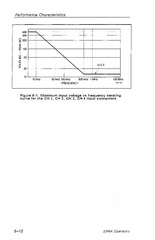
Performance Characteristics
10 kHz 50 kHz 100 kHz 500 kHz 1 MHz 100 MHz FREQUENCY 4207.28
Figure 6-1. Maximum input volta e vs frequency derating curve for the CH 1 , CH 2, CH 3, 8~ 4 input connectors.
2245A Operators

Performance Characteristics
Table 6-2
Environmenta l Character is t ics
CHARACTERISTICS I DESCRIPTION I
STANDARD INSTRUMENT
Environmental Requirements
Temperature 9
Altitude - Operating
Non-Operating
Humidity (Operating and Non-operating)
Radiated and conducted Emission required per VDE 0871
Instrument meets or exceeds the environmental requirements of MIL-T-28800D for Type HI, Class 3, Style D equipment.?
-51" C to +71°C (-60° F to t160° F) .
Tested to MIL-T-28800D paragraphs 4.5.5.1.3 and 4.5.5.1.4, except in 4.5.5.1.3, steps 4 and 5 ( - 10 °C operating test) are performed ahead of step 2 ( -51 " C non-operating test ) . Equipment shall remain off upon return to room ambient during step 6. Excessive conden- sation shall be removed before operating during step 7.
To 4,570 m (15,000 f t ) . Maximum operating temperature decreases lo C per 1000 f t above 5000 ft.
To 15,240 m (50,000 f t ) .
Five cycles (120 hours) referenced to MIL-T-28800D paragraph 4.5.5.1.2.2, for type Ill, class 3 instruments.
Non-operating and operating at 95%, -0% to +2% relative humidity. Operating at +30° C and +55" C for all modes of operation. Non-operating at +30 " C to +60° C .
Meets Category B.
aPerformance not checked in manual.
2245A Operators

Performance Characteristics
Table 6-2 (cont)
Envi ronmenta l Character is t ics
DESCRIPTION
Withstands discharge of up t o 20kV. Test performed with probe containing a 500 pF capacitor with 1 kSZ resistance charged to the test voltage.
Conforms to Tektronix Standard 062-2862-00.
15 minutes along each of 3 major axes at a total displacement of 0.25 inch p-p (4 g at 55 Hz) with frequency varied from 10 Hz to 55 Hz in 1-minute sweeps. Hold from 10 minutes at 55 Hz in each of the three major axes. All major resonances must be above 55 Hz.
MIL-STD-81 OD, Method 51 6.3, Procedure VI (MIL-T-28800D, Paragraph 4.5.5.4.3).
Meets the limits of the National Safe Transit Association test procedure 1A-B-l ; excursion of 1 inch p-p at 4.63 Hz (1.1 g) for 30 minutes on the bottom and 30 minutes on the side (for a total of 60 minutes).
Meets the limits of the National Safe Transit Association test procedure 1 A-B-2 ; 10 drops of 36 inches.
2245A Operators

Performance Characteristics
Table 6-3
Mechan ica l Character is t ics
CHARACTERISTICS I DESCRIPTION
STANDARD INSTRUMENT
Weight
With Front Cover, Accessories, and Accessories Pouch (without manual)
With Power Cord
Shipping Weight (Domestic)
Overall Dimensions
Height
With Feet and Accessories Pouch (empty)
Without Accessories Pouch
Width (with handle)
Depth
With Front Cover on
With Handle Extended
Cooling
Finish
Construction
8.9 kg (19.5 lb) .
7.9 kg (17.3 lb).
11.7 kg (25.8 Ib).
See Figure 6-2, dimensional outline drawing.
Approx. 176.5 m m (6.95 in).
163.6 m m (6.44 in).
360.4 m m (14.19 in) .
445.3 m m (17.53 in).
518.9 m m (20.43 in).
Forced air clrculation; no air filter.
Tek Blue, pebble-grain finish painted on aluminum cabinet.
Aluminum alloy chassis. Plastic-laminate front panel.
2245A Operators

Performance Characteristics
Table 6-3 (cont)
Mechan ica l Character is t ics
Weight
With Power Cord
I Shipping Weight
CHARACTERISTICS
Domestic, includes manual
DESCRIPTION
Overall Dimensions
Height
Overall
RACKMOUNT INSTRUMENT
Center of mounting rail to bottom of cabinet
From cabinet top or bottom to respective front- panel mounting holes
Between front- panel mounting holes
Width
Overall
Between mounting hole centers
Between outer edges of mounting rails
Between handle centers
10.0 kg (22.0 Ib).
14.2 kg (31.3 Ib).
See Figure 6-3, Dimensional drawing
168 m m (6.6 in) .
89 m m (3.5 in) .
38 m m (1.5 in) .
102 m m (4.0 in).
483 m m (19.0 in).
464 m m (18.3 in).
427 m m (16.8 in).
450 m m (17.7 in)
2245A Operators

Performance Characteristics
Table 6-3 (cont)
Mechanical Characterist ics
CHARACTERISTICS 1 DESCRIPTION
Depth
Overall
Front panel to rear of mounting rail (inside)
516 mm (20.35 in) .
465 mm (1 8.3 in).
Front panel to rear of mounting rail (outside)
Required Clearance dimensions
472 mm (18.6 in) .
Handles
Width 4 448 mm ( 1 7-518 in).
Cooling Forced air circulation; no air filter.
44 mm (1.75 in).
Finish
I
I Tek Blue, pebble-grain finish painted on aluminum cabinet.
Construction Aluminum alloy chassis, front-panel frame, and rear support. Plastic-laminate front panel. Glass-laminate circuit boards.
2245A Operators

Performance Characteristics
D i r n e n s ~ o n s a r e In i n c h e s [ m m ] 6558-24
Figure 6-2. Dimensional drawing, standard cabinet.
2245A Operators

Performance Characferistics
2.0 in
RECOMMENDED I AT REAR AND
SIDES FOR COOLING AN0 I INSTRUMENT
CONNECTIONS 18.8 in
427 mm
I 1 TOP VIEW L - - --
38 rnm
LEFT S IDE VIEW 4 - 1 1.750 in
44 mm
FRONT VIEW
Figure 6-3. Dimensional drawing, rackmount cabinet (224OFl R) .
2245A Operators

This Document was scanned from the original Tektronix Service Manual
For enquiries about high quality technical manuals
This Document is a complete Scan from the original Tektronix manual For enquiries about our complete High quality line of technical Manuals in PDF
mailto : [email protected]

SECTION 7
PERFORMANCE CHECK
PROCEDURE
2245A Operators

This Document was scanned from the original Tektronix Service Manual
For enquiries about high quality technical manuals
This Document is a complete Scan from the original Tektronix manual For enquiries about our complete High quality line of technical Manuals in PDF
mailto : [email protected]

Performance Check Procedure
INTRODUCTION
This Performance Check Procedure verifies the Performance Requirements of the 2245A as listed in the Performance Characteristics (Section 6) and helps determine the need for readjustment. These checks may also be used as an acceptance test or as a preliminary troubleshooting aid.
You do not have to remove the wrap-around cabinet from the 2245A to do this procedure. Ail checks can be made with controls and connectors ac- cessible from the outside.
Test Equipment Required
Table 7-1 lists all the test equipment required to do the Performance Check Procedure. Test equipment specifications described are the minimum nec- essary to provide accurate results. For test equipment operating informa- tion, refer to the appropriate test equipment instruction manual.
When you use equipment other than that recommended, you may have to make some changes to the test setups. if the exact example equipment in Table 7-1 is not available, use the Minimum Specification column to deter- mine if any other available test equipment might be adequate to do the check.
Performance Check Interval
To ensure instrument accuracy, check the performance of the 2245A after every 2000 hours of operation, or once each year if used infrequently. If the checks indicate a need for readjustment or repair, refer the instrument to a qualified service person.
Preparation
This procedure is divided into subsections to let you check individual sec- tions of the instrument when it is not necessary to do the complete Per- formance Check. An Equipment Required block at the beginning of each subsection lists the equipment from Table 7-1 that is needed to do the checks in that subsection.
2245A Operators

Performance Check Procedure
The initial front-panel control settings at the beginning of each subsection prepare the instrument for the first step of the subsection. Do each of the steps in a subsection completely and in order to ensure the correct control settings for steps that follow. To ensure performance accuracies stated in the Performance Characteristics (Section 6 ) , let the instrument warm up for 20 minutes and run the SELF CAL MEASUREMENTS routine.
To run the SELF CAL MEASUREMENTS routine:
Press the CH 1 and CHOPIALT VERTICAL MODE buttons at the same time to display the SERVICE MENU. Underline and select SELF CAL MEASURE- MENTS by pressing the ADD button. Press RUN (CH 2 button) to start the routine, then QUIT (CH 4 button) to return to the normal oscilloscope mode.
NOTE
Performance accuracies are ensured only when the SELF CAL MEASUREMENTS is done AFTER the 20-minute warmup.
2245A Operators

Performance Check Procedure
Table 7-1 Test Equ ipment Required
M i n i m u m Speci f icat ion
Frequency: 250 kHz to above 150 MHz. Output am- plitude: variable from 10 mV to 5 V p-p. Output impedance: 50 fi Amplitude accuracy: con- stant within 1 .5% of reference frequency to 100 MHz.
Standard- amplitude signai levels (Dc and Square wave) : 5 m V to 50 V. Accuracy:? 0.25% High-amplitude signal levels: 1 V to 60 V. Repetitior rate: 1 kHz. Fast-rise signai level: 1 V. Repe- tition rate: l MHz. Rise time: 1 ns or less. Flatness: 20.5%.
Marker outputs: 5 ns to 0.5 s. Marker accuracy: 20.1%. Trigger output: 1 ms to 0.1 IS, time- coincident with markers.
Range: less than 1 Hz to 1 kHz; sinusoidal output; amplitude variable up t o greater than 10 V p-p open circuit with dc offset adiust.
a~equ i res a TM500-series power module.
2245A Operators
Use
Vertical, hori- zontal, trigger- ing, measure- ment bandwidth, and Z-Axis checks and adjustments.
Signal source for gain and transient re- sponse checks and adjustments
Horizontal check and adjustments Display adjust- ment. Time cursor checks.
Low-frequency checks.
Examole of res t ~ ~ u i p m e n t
TEKTRONiX SG 503 Leveled Sine-Wave en era tor .a
TEKTRONIX PG 506 Calibration Generator .a
TEKTRONIX TG 501 Time-Mark Generat0r.a
TEKTRONiX FG 502 Function G e n e r a t ~ r . ~

Performance Check Procedure
Table 7-1 (cont)
I tem and Descr ip t ion
Coaxial Cable (2 required)
Precision Coaxial Cable
Tektronix Part Number 011-0049-01.
Termination (2 required)
M i n i m u m Speci f icat ion
Impedance: 50 a Length: 42 in. Connectors: BNC
Impedance: 50 a Length: 36 in. Connectors: BNC
Tektronix Part Number 011-0059-02.
Impedance: 50 a Connectors: BNC
10X Attenuator
Tektronix Part Number
Connectors: BNC 011-0069-02.
male-to- connection. Number miniature-probe 013-0084-02. tip.
Use
Signal inter- connection.
Used with PG 506 Calibration Generator and SG 503 Sine- Wave Generator.
Signal termi- nation.
Alignment Tool
Example of Test Equipment
Tektronix Part Number 012-0057-01.
Tektronix Part Number 01 2-0482-00.
Ratio: 10X. Impedance: 50 a Connectors: BNC
Length: 1-in shaft. Bit size: 3/32 in. Low capacitance; insulated. capacitors and
resistors.
Triggering checks.
- -
Tektronix Part Number 003-0675-00.
Precision Normalizer
Test Oscilioscope
Dual-Input Coupler
Tektronix Part connection. Number
103-0030-00.
Bandwidth: 20 MHz.
Connectors: BNC female-to-dual- BNC male.
REV JUN 1989
Capacitance: 22 pF.
2245A Operators
2-Axis Response adjustment.
Signal inter- connection.
TEKTRONIX 2246A.
Tektronix Part Number 067-0525-02
ments. 067-0538-00.

Performance Check Procedure
Table 7-1 (cont)
I tem and M in lmum Descript ion Specif ication
Generator Sync Signals.
Example of Test Equipment
TEKTRONIX TSG- 100 Test Signal Generator.
TEKTRONIX DM501 A Digital M ~ i t i m e t e r . ~
Digital Muitimeter (DMM)
a~equires a TM500-series power module
2245A Operators
Dc Volts Range: 0 to 140 V. Dc Voltage accuracy: 5 0.15%. 4 112 diait diswlav.
Power supply voltage checks and adjustments

Performance Check Procedure
INDEX TO PERFORMANCE CHECK PROCEDURE
DISPLAY
. . . . . . . . . . . . . . . . . . . . . . . . . . . . . . . . . . 1 . TRACE ROTATION 7-8 . . . . . . . . . . . . . . . . . . . . . . . . . . . . . . . . . . . . . . . . . . 2 . Geometry 7-9
VERTICAL
1. Input COUPLING Functional Check . . . . . . . . . . . . . . . . . . . . 7-10 2 . CH 1 and CH 2 VOLTSIDIV Trace Shift . . . . . . . . . . . . . . . . 7-11 3 . CH 3 and CH 4 VOLTSIDIV Trace Shift . . . . . . . . . . . . . . . . 7-12 4 . CH 1 and CH 2 VAR VOLTSIDIV Trace Shift . . . . . . . . . . 7-12 5 . CH 1 and CH 2 Input COUPLING Trace Shift . . . . . . . . . . . 7-13 6 . CH 2 INVERT Trace Shift . . . . . . . . . . . . . . . . . . . . . . . . . . . 7-13 7 . CH 1 and CH 2 VAR VOLTSIDIV Range . . . . . . . . . . . . . . . 7-13 8 . Low Frequency Linearity . . . . . . . . . . . . . . . . . . . . . . . . . . . . 7-14 9 . CH 1 and CH 2 Vertical Deflection Accuracy . . . . . . . . . . . 7-15
10 . CH 3 and CH 4 Vertical Deflection Accuracy . . . . . . . . . . . 7-16 11 . ADD Mode and CH 2 INVERT Deflection Accuracy . . . . . . 7-17 12 . Vertical POSITION Range (all channels) . . . . . . . . . . . . . . . . 7-18 13 . CH 1 to CH 2 Signal Delay Match . . . . . . . . . . . . . . . . . . . . . 7-19 14 . CH 1 to CH 4 Signal Delay Match . . . . . . . . . . . . . . . . . . . . . 7-20 15 . CH 3 to CH 4 Signal Delay Match . . . . . . . . . . . . . . . . . . . . . 7-20 16 . CH 1 and CH 2 Vertical Bandwidth . . . . . . . . . . . . . . . . . . . . 7-21 17 . CH 3 and CH 4 Vertical Bandwidth . . . . . . . . . . . . . . . . . . . . 7-22 18 . SCOPE BW (Bandwidth Limit) Accuracy . . . . . . . . . . . . . . . 7-22 19 . Common-Mode Rejection Ratio . . . . . . . . . . . . . . . . . . . . . . 7-23 20 . Channel Isolation . . . . . . . . . . . . . . . . . . . . . . . . . . . . . . . . . . . 7-24 21 . AC-Coupled Lower -3 dB Point . . . . . . . . . . . . . . . . . . . . . . 7-25 22 . Vertlcal ALT and CHOP Mode . . . . . . . . . . . . . . . . . . . . . . . . 7-26 23 . BEAM FIND Functional Check . . . . . . . . . . . . . . . . . . . . . . . 7-26 24 . A and B Trace Separation . . . . . . . . . . . . . . . . . . . . . . . . . . . 7-27
TRIGGERING
1 . 500 Hz Trigger Sensitivity . . . . . . . . . . . . . . . . . . . . . . . . . . . . 7-28 2 . 500 kHz Trigger Sensitlvity . . . . . . . . . . . . . . . . . . . . . . . . . . . 7-29 3 . 25 MHz Trigger Sensitivity . . . . . . . . . . . . . . . . . . . . . . . . . . . . 7-30 4 . 150 MHz Trigger Sensitivity . . . . . . . . . . . . . . . . . . . . . . . . . . . 7-31 5 . Single Sweep Mode . . . . . . . . . . . . . . . . . . . . . . . . . . . . . . . . . 7-32 6 . Trigger LEVEL Control Range . . . . . . . . . . . . . . . . . . . . . . . . 7-33 7 . TV Field Trigger Sensitivity . . . . . . . . . . . . . . . . . . . . . . . . . . . 7-34 8 . TV Line Trigger Sensitivity . . . . . . . . . . . . . . . . . . . . . . . . . . . 7-34 9 . Line Trigger Functional Check . . . . . . . . . . . . . . . . . . . . . . . . 7-35
2245A Operators
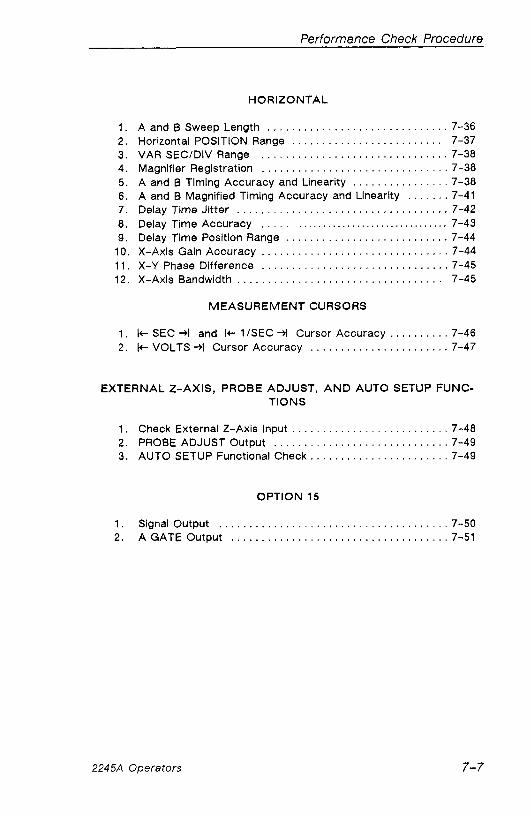
Performance Check Procedure
HORIZONTAL
1 . A and B Sweep Length . . . . . . . . . . . . . . . . . . . . . . . . . . . . . . 7-36 2 . Horizontal POSITION Range . . . . . . . . . . . . . . . . . . . . . . . . . 7-37 3 . VAR SECIDIV Range . . . . . . . . . . . . . . . . . . . . . . . . . . . . . . . 7-38 4 . Magnifier Registration . . . . . . . . . . . . . . . . . . . . . . . . . . . . . . . 7-38 5 . A and B Timing Accuracy and Linearity . . . . . . . . . . . . . . . . 7-38 6 . A and B Magnified Timing Accuracy and Linearity . . . . . . . 7-41
. . . . . . . . . . . . . . . . . . . . . . . . . . . . . . . . . . . 7 . Delay Time Jitter 7-42 8 . Delay Time Accuracy . . . . . . . . . . . . . . . . . . . . . . . . . . . . . . . . . . . . 7-43 9 . Delay Time Position Range . . . . . . . . . . . . . . . . . . . . . . . . . . . 7-44
10 . X-Axis Gain Accuracy . . . . . . . . . . . . . . . . . . . . . . . . . . . . . . . 7-44 11 . X-Y Phase Difference . . . . . . . . . . . . . . . . . . . . . . . . . . . . . . . 7-45 12 . X-Axis Bandwidth . . . . . . . . . . . . . . . . . . . . . . . . . . . . . . . . . . 7-45
MEASUREMENT CURSORS
. . . . . . . . . . 1 . I+- SEC 4 and I+ 1ISEC +I Cursor Accuracy 7-46 . . . . . . . . . . . . . . . . . . . . . . . . 2 I t VOLTS -+I Cursor Accuracy 7-47
EXTERNAL Z.AXIS. PROBE ADJUST. A N D AUTO SETUP FUNC- TIONS
1 . Check External 2-Axis Input . . . . . . . . . . . . . . . . . . . . . . . . . . 7-48 2 . PROBE ADJUST Output . . . . . . . . . . . . . . . . . . . . . . . . . . . . . 7-49 3 . AUTO SETUP Functional Check . . . . . . . . . . . . . . . . . . . . . . . 7-49
OPTION 15
1 . Signal Output . . . . . . . . . . . . . . . . . . . . . . . . . . . . . . . . . . . . . . 7-50 2 . A GATE Output . . . . . . . . . . . . . . . . . . . . . . . . . . . . . . . . . . . . 7-51
2245A Operators

Performance Check Procedure
DISPLAY
Equipment Required (See Table 7-1)
Time mark generator
50 BNC termination
50 BNC coaxial cable
1. TRACE ROTATION
a. Set:
READOUT (Intensity) A INTEN VERTICAL MODE CH 1 VOLTS/DIV CH 1 COUPLING SCOPE BW AIB SELECT TRIGGER MODE TRIGGER SOURCE TRIGGER CPLG TRIGGER SLOPE TRIGGER HOLDOFF TRIGGER LEVEL Horizontal MODE Horizontal POSITION
A SECIDIV CLEAR MEAS'MT
FOCUS
For a viewable readout For a viewable trace CH 1 0.1 v AC Off A Trigger AUTO LEVEL VERT DC f (positive-going) Min 12 o'clock A 12 o'clock
Press to remove measurement cursors. For best defined display
b . Position trace vertically t o the center graticule line.
c . CHECK-trace rotation control range is adequate t o align trace with center graticule line using a small straight-bladed alignment tool.
d. ADJUST-trace parallel to center horizontal graticule line.
2245A Operators

Performance Check Procedure
2 . Geometry
Connect time mark generator (TG 501 ) to CH 1 via a 50 a BNC coax-
ial cable and a 50 BNC termination.
Set generator for 0.2 p s time marks.
Position the bottom of the CH 1 signal below the bottom graticule line. It may be necessary to increase the A intensify in order to see the time markers.
CHECK-deviation of any vertical line within the center eight horizontal divisions does not exceed 0.1 division (half a minor division).
Set CH 1 COUPLING to GND
Position trace slowly from the bottom graticule line to the top graticule line while making the following check.
CHECK-bowing or tilt of baseline trace doesn't exceed 0.1 division (half a minor division) within the eight vertical divisions.
Disconnect test signal from the 2245A.
2245A Operators

Performance Check Procedure
VERTICAL
Equipment Required (See Table 7-1) I Leveled sine-wave generator 50 a precision BNC coaxial cable
Calibration generator 50 termination
Function generator Dual-input coupler
50 BNC coaxial cable
1. lnput COUPLING Functional Check
a. Set:
READOUT (Intensity) A INTEN VERTICAL MODE CH 1 and CH 2 VOLTSIDIV CH 1 and CH 2 lnput COUPLING SCOPE BW CH 2 INVERT AIB SELECT TRIGGER MODE TRIGGER SOURCE TRIGGER CPLG TRIGGER SLOPE TRIGGER LEVEL TRIGGER HOLDOFF Horizontal POSITION Horizontal MODE SECIDIV FOCUS CLEAR MEAS' MT
b. Set Vertical MODE to CH 1 (CH 2 off)
For a viewable readout For a viewable trace CH 1 and CH 2
DC Off Off A TRIGGER AUTO LEVEL VERT DC f (positive-going) 12 o'clock Min 12 o'clock A 0.5 ms For best defined display Press to remove measurement cursors
c . Connect Function Generator (FG 502) sine-wave output to the CH 1
input vla a 50 !2 BNC coaxial cable and a 50 BNC termination.
2245A Operators

Performance Check Procedure
Set function generator output for 1 kHz sine-wave signal of five divi- sions peak-to-peak with maximum positive dc offset.
Position the bottom of the signal to the center horizontal graticuie line.
Set CH 1 lnput COUPLING to AC.
CHECK-display is roughly centered about the center horizontal graticule line.
Move the test signal to the CH 2 input.
Set CH 2 VERTICAL MODE to on (CH 1 off).
Repeat the procedure for CH 2 .
Disconnect the test signal from the 2245A.
2 . CH 1 and CH 2 VOLTSIDIV Trace Shift
a. Set:
CH 1 and CH 2 VERTICAL MODE On CH 1 and CH 2 VOLTSIDIV 2 mV CH 1 and CH 2 Input COUPLING GND
Set VERTICAL MODE to CH 1 (CH 2 of f ) .
Position trace to center horizontal graticule line.
Switch CH 1 VOLTSIDIV through all positions from 2 mV to 5 V.
CHECK-trace shift does not exceed 0.2 division between steps.
Set VERTICAL MODE to CH 2 (CH 1 of f ) .
Position CH 2 trace to the center horizontal graticule line.
Switch CH 2 VOLTSIDIV through all positions from 2 mV to 5 V.
CHECK-trace shlft does not exceed 0.2 divislon between steps.
2245A Operators

Performance Check Procedure
3. C H 3 and C H 4 VOLTSIDIV Trace Shif t
Set VERTICAL MODE to CH 3 (CH 2 o f f ) .
Position trace to the center horizontal graticule line.
Switch CH 3 VOLTSIDIV between 0.1 V and 0.5 V.
CHECK-trace shift does not exceed one division.
Set VERTICAL MODE to CH 4 (CH 3 o f f ) .
Position trace to the center horizontal graticule line.
Switch CH 4 VOLTSIDIV between 0.1 V and 0.5 V.
CHECK-trace shift does not exceed one division.
4 . C H 1 a n d C H 2 VAR VOLTSIDIV Trace Shif t
a . Set:
VERTICAL MODE CH 1 (CH 4 off) CH 1 VOLTSIDIV 2 mV
b. Position trace t o center graticule line.
c . Set CH 1 VAR VOLTSIDIV fully CCW (counterclockwise).
d . CHECK-trace shift does not exceed one division.
e. Set:
CH 1 VAR VOLTSIDiV Detent (calibrated) VERTICAL MODE CH 2 (CH 1 off) CH 2 VOLTSIDIV 2 mV
f. Position trace to center graticule line.
g. Set CH 2 VAR VOLTS/DiV fuiiy CCW.
h. CHECK-trace shift does not exceed one division.
i . Set CH 2 VAR VOLTSIDIV to detent (calibrated) position.
2245A Operators

Performance Check Procedure
5 . CH 1 and CH 2 lnput COUPLING Trace Shlft
Position trace to center graticule line.
Set CH 2 lnput COUPLING to DC.
CHECK-trace shift does not exceed 0.25 division.
Set:
VERTICAL MODE CH 1 (CH 2 off) CH 1 Input COUPLING GND
Position trace to center graticule line.
Set CH 1 lnput COUPLING to DC.
CHECK-trace shift does not exceed 0.25 division.
6. CH 2 INVERT Trace Shift
a. Set:
VERTICAL MODE CH 2 lnput COUPLING
CH 2 (CH 1 off) GND
b. Position trace to center horizontal graticule line.
c. Set CH 2 INVERT On.
d. CHECK-trace shift does not exceed one division.
e. Set:
CH 2 INVERT Off CH 2 l n ~ u t COUPLING DC
7. CH 1 and CH 2 VAR VOLTSIDIV Range
a. Set VERTICAL MODE to CH 1 (CH 2 off).
b. Position CH 1 and CH 2 traces to the center horizontal graticule line.
2245A Operators 7-13

Performance Check Procedure
Set:
CH 1 VOLTSIDIV 10 mV CH 1 VAR VOLTSIDIV Fully CCW
Connect calibration generator (PG 506) Std Ampl output to the CH 1
input via a 50 fi precision BNC coaxial cable. Set generator Std Ampl output to 50 mV.
CHECK-the signal amplitude is two divisions or less.
Set:
CH 1 VAR VOLTSlDlV Detent (calibrated) Vertical MODE CH 2 (CH 1 off) CH 2 VOLTSIDIV 10 mV
Position CH 2 trace to the center horizontal graticule line.
Move the test signal to the CH 2 input.
Set CH 2 VAR VOLTSIDIV fully CCW.
Repeat the CHECK procedure for CH 2.
Set CH 2 VAR VOLTSIDIV to detent (calibrated) position.
8. Low-Frequency Linearity
a. Set:
VERTICAL MODE CH 1 VOLTSIDIV SCOPE BW
CH 1 (CH 2 off) 10 mV 0 N
b. Set calibration generator to Std Ampl output, 20 mV.
c . Move the test signal to the CH 1 input.
d. Position the top of the signal to top graticule line.
e. CHECK-the signal amplitude is between 1.9 and 2.1 divisions.
f . Set bottom of the signal to bottom graticule line.
2245A Operators

Performance Check Procedure
g. CHECK-the signal amplitude is between 1.9 and 2.1 divisions.
h. Repeat the procedure for CH 2 .
9 . CH 1 and CH 2 Vert ical Deflection Accuracy
a. Set CH 2 VOLTSIDIV to 2 mV.
b. Set calibration generator to Std Ampl output, 10 mV.
c . Position the trace two graticule lines below the center horizontal graticule line.
d. CHECK-all positions of the VOLTSIDIV settings for correct signal to graticule accuracy, using the settings in Table 7-2, Signal-to- Graticuie Accuracy, for the checks.
e. Set calibration generator to Std Ampl output, 10 mV.
f. Move the test signal to the CH 1 input.
g. Set:
VERTICAL MODE CH 1 VOLTSIDIV
h. Same as c . above
i. Repeat CHECK procedure for CH 1 .
CH 1 (CH 2 off) 2 mV
2245A Operators

Performance Check Procedure
Table 7-2 Signal-to-Grat icule Accu racy
VOLTSIDIV Set t ing
2 m V
5 mV
10 mV
20 m V
50 m V
0.1 v 0.2 v 0.5 v
1 v 2 v 5 v
S td A m p l Se t t ing
Def lect ion Accy . ( in d iv is ions)
4.90 to 5.10
3.92 to 4.08
4.90 t o 5.10
4.90 to 5.10
3.92 t o 4.08
4.90 to 5.10
4.90 to 5.10
3.92 t o 4.08
4.90 to 5.10
4.90 to 5.10
3.92 to 4.08
10. CH 3 a n d CH 4 Ver t i ca l Def lect ion Accu racy
Set:
VERTICAL MODE CH 3 (CH 1 off) CH 3 VOLTSIDIV 0.1 V
Position the trace to the second graticule line down from the center horizontal graticule line.
Move the test signal to the CH 3 input.
Set calibration generator t o Std Ampl output, 0.5 V.
CHECK-the signal amplitude is between 4.90 and 5.10 divisions.
Move the test signal to the CH 4 input.
Set:
VERTICAL MODE CH 4 (CH 3 off) CH 4 VOLTSIDIV 0.1 V
2245A Operators

Same as b . above.
Repeat CHECK for CH 4.
Set CH 3 and CH 4 VOLTSIDIV t o 0.5 V .
Set calibration generator t o Std Ampl output, 2 V.
CHECK-the signal amplitude is between 3.92 and 4.08 divisions.
Set:
VERTICAL MODE CH 3 (CH 4 off) CH 3 VOLTSIDIV 0.5 V
Move the test signal t o the CH 3 input.
Repeat CHECK procedure for CH 3.
Disconnect the test setup from the 2245A.
A D D M o d e a n d CH 2 INVERT Def lect ion Accu racy
Set:
VERTICAL MODE ADD (all others off) CH 1 and CH 2 VOLTSIDIV 0.1 V CH 1 and CH 2 Input COUPLING DC
Connect calibration generator Std Ampl output to the CH 1 and CH 2
inputs via a 50 precision BNC coaxial cable and a BNC dual-input coupler.
Set the calibration generator to Std Ampl output, 0.2 V.
Position the ADD signal t o the center of the cr t graticule with the CH 1 and CH 2 POSITION controls.
CHECK-That the ADD signal amplitude is between 3 .92 and 4.08 divi- sions.
Set CH 2 INVERT On.
CHECK-That the ADD signal amplitude is 0.08 division (less than half a minor graticule division) or less excluding trace width (sweep will free run) .
Disconnect the test setup from the 2245A.
Performance Check Procedure
2245A Operators

Performance Check Procedure
12. Vertlcal POSITION Range (all channels)
Set:
A SECJDIV 0.1 ms VERTICAL MODE CH 1 (ADD off) CH 1 VOLTSIDIV 1 V CH 2 INVERT Off SCOPE BW Off CH 1 and CH 2 Input COUPLING AC
Connect leveled sine-wave generator (SG 503) output to the CH 1 and
CH 2 inputs via a 50 fi BNC coaxial cable, a 50 fi BNC termination, and a BNC dual-input coupler.
Position trace to center horizontal graticule line.
Set leveled sine-wave generator output for two-division signal at 50 kHz.
Set:
CH 1 VOLTSIDIV 0.1 V CH 1 POSITION Fully CW (clockwise)
CHECK-that the bottom of the waveform is at least one division above the center horizontal graticule line.
Set CH 1 POSITION fully CCW.
CHECK-that the top of the waveform is at least one division below the center horizontal graticule line.
Set:
CH 1 POSITION 12 o'clock VERTICAL MODE CH 2 (CH 1 off) CH 2 POSITION Fully CW
CHECK-that the bottom of the waveform is at least one division above the center horizontal graticule line.
Set CH 2 POSITION fully CCW.
CHECK-that the top of the waveform is at least one division below the center horizontal graticule line.
2245A Operators

Performance Check Procedure
Set CH 2 POSITION to 12 o'clock.
Move the BNC dual-input coupler from the CH 1 and CH 2 inputs to the CH 3 and CH 4 inputs.
Set:
VERTICAL MODE CH 3 (CH 2 off) CH 3 and CH 4 VOLTSIDIV 0.1 V CH 3 POSITION Fully CW
CHECK-that the bottom of the waveform is at least one division above the center graticule line.
Set CH 3 POSITION fully CCW.
CHECK-that the top of the waveform is at least one division below the center graticule line.
Set:
CH 3 POSITION 12 o'clock VERTICAL MODE CH 4 (CH 3 off)
Repeat the procedure for CH 4.
Set CH 4 POSITION to 12 o'clock.
Disconnect the test setup from the 2245A.
13. CH 1 t o CH 2 Signal Delay M a t c h
a. Set:
VERTICAL MODE CH 1 and CH 2 (CH 4 off) CH 1 and CH 2 Input COUPLING DC CH 1 and CH 2 VOLTSIDIV 0.1 V SECIDIV 20 ns TRIGGER SOURCE CH 3
b. Superimpose the CH 1 and CH 2 traces at the 100% gratlcule marking.
2245A Operators 7-19

Performance Check Procedure
Connect calibration generator (PG 506) fast rise, rising-edge signal to
the CH 1 and CH 2 inputs via a 50 a precision BNC coaxial cable, a
50 a BNC termination, and a BNC dual-input coupler.
Connect calibration generator trig out signal to the CH 3 input via a
50 a BNC coaxial cabie and a 50 BNC termination.
Set the calibration generator to Fast Rise and adjust Pulse Amplitude for five divisions of signal amplitude at 1 MHz.
Position the rising edges of the superimposed waveforms horizontally to the center vertical graticule line.
NOTE
It may be necessary to readjust the trigger level to display the rising-edge signal in the Delay Match steps. This can be done by pressing the upper Trigger MODE button to cause the trigger level to be automatically readjusted.
Set XI0 MAG On (for 2 nsldiv sweep speed).
CHECK-that the leading edges of the two waveforms have less than 0.1 horizontal division separation at the center graticule line excluding trace width.
CH 1 to CH 4 Signal Delay Ma tch
Set VERTICAL MODE to CH 1 and CH 4 (CH 2 off)
Move the CH 2 signal to the CH 4 input connector
Superimpose the CH 4 waveform on the CH 1 waveform.
CHECK-that the leading edges of the two waveforms have less than 0.1 horizontal division separation at the center graticuie line excluding trace width.
15. CH 3 t o CH 4 Signal Delay M a t c h
a. Set:
VERTICAL MODE TRIGGER SOURCE
CH 3 and CH 4 (CH 1 off) CH 2
b . Move the CH 3 signal to the CH 2 input and the CH 1 trigger signal to the CH 3 input.
2245A Operators

Performance Check Procedure
c . Superlmpose CH 3 and CH 4 waveforms at the center graticule line.
d. CHECK-that the leading edges of the two waveforms have less than 0.1 horizontal division separation at the center graticuie line.
e. Disconnect the test setup.
16. CH 1 and CH 2 Vert ical Bandwidth
Set:
XI0 MAG Off VERTICAL MODE CH 1 (CH 3 and CH 4 off) SECIDIV 0.1 ms CH 1 VOLTSIDIV 5 mV CH 1 and CH 2 Input COUPLING DC TRIGGER SOURCE VERT Horizontal POSITION 12 o'clock
Connect leveled sine-wave generator (SG 503) output to the CH 1 in-
put via a 50 n precision BNC coaxial cable and a 50 n BNC termina- tion.
Set the leveled sine-wave Generator output for a six-division signal amplitude at 50 kHz.
Set the generator Frequency Range and Frequency Variable controls for a 90 MHz output signal.
CHECK-the displayed signal amplitude is 4 . 2 divisions or more as the frequency is increased to 100 MHz.
Repeat the frequency setup and CHECK procedure for VOLTSIDIV settings of 50 mV through 0.5 V.
Move the test signal to the CH 2 input.
Set:
VERTICAL MODE CH 2 VOLTSIDIV
CH 2 (CH 1 off) 5 mV
Repeat the complete Bandwidth check procedure for Channel 2 .
22454, Operators

Performance Check Procedure
17. C H 3 a n d C H 4 Vert ica l Bandwid th
a. Set:
VERTICAL MODE CH 3 (CH 2 off)
CH 3 and CH 4 VOLTSiDlV 0.1 V
Connect leveled sine-wave generator (SG 503) output to the CH 3 in-
put via a 50 precision BNC coaxial cable and a 50 fi BNC termina- tion.
Set the generator output for a six-division signal display at 50 kHz.
Set the generator Frequency Range and Frequency Variable controls for a 90 MHz output frequency.
CHECK-that the signal display amplitude is 4 . 2 divisions or more as the frequency is increased to 100 MHz.
Repeat the procedure for 0.5 VOLTSIDIV setting.
Move the test signal t o the CH 4 input.
Set VERTICAL MODE to CH 4
Repeat the procedure for CH 4 .
SCOPE B W (Bandwid th Limit) Accu racy
Set:
VERTICAL MODE CH 1 VOLTS/DiV SCOPE BW
CH 1 (CH 4 off) 10 mV On
Move test signal from the CH 4 input to the CH 1 input.
Set leveled sine-wave generator (SG 503) output for a six-division sig- nal amplitude at 50 kHz.
Increase the leveled sine-wave generator output frequency, using the Frequency Range and Frequency Variable controls until a signal display amplitude of 4 . 2 divisions is obtained.
2245A Operators

Performance Check Procedure
e. CHECK-that the sine-wave generator output frequency is between 17 MHz and 23 MHz.
f . Disconnect the test setup
19. Common-Mode Rejection Ratio
a. Connect leveled sine-wave generator (SG 503) output to the CH 1 and
CH 2 input connectors via a 50 R precision BNC coaxial cable, a 50
BNC termination, and a 9NC dual-input coupler.
b . Set the leveled sine-wave generator output for an eight-division signal- display amplitude at 50 kHz.
c . Set:
VERTICAL MODE CH 2 VOLTS/DIV CH 2 INVERT SCOPE BW
ADD (CH 1 off) 10 mV On Off
d. Adjust CH 1 or CH 2 VAR VOLTS/DIV(as needed) for smallest signal am~litude.
e. Set the leveled sine-wave output frequency to 50 MHz.
f . Set the VERTICAL MODE to CH 1 (ADD off)
g. Set the leveled sine-wave output amplitude for an eight-division dis- play.
h. Set the VERTICAL MODE to ADD (CH 1 off).
i. CHECK-the signal is less than 0.8 division in amplitude.
j . Disconnect the test setup.
2245A Operators

Performance Check Procedure
20. Channel Isolation
Set:
CH 1 and CH 2 VERTICAL MODE On (ADD off) CH 2 INVERT Off CH 1, CH 2 , CH 3, and CH 4 VOLTSIDIV 0.1 V TRIGGER SOURCE CH 1
Connect the leveled sine-wave generator (SG 503) output to the CH 1
input via a 50 fi precision BNC coaxial cable and a 50 fi BNC termina- tion.
Set the leveled sine-wave generator (SG 503) output for a five-division signal display amplitude at 100 MHz.
Set CH 2 , CH 3, and CH 4 VERTICAL MODE On (CH 1 of f ) ,
CHECK-display amplitude is 0.1 division or less, excluding trace width, on the CH 2 , CH 3, and CH 4 traces.
Move sine-wave generator signal to the CH 2 input.
Set:
CH 1, CH 3, and CH 4 VERTICAL MODE On (CH 2 off) TRIGGER SOURCE CH 2
CHECK-display amplitude is 0.1 division or less, excluding trace width, on the CH 1, CH 3, and CH 4 traces.
Move sine-wave generator signal to the CH 3 Input.
Set:
CH 1, CH 2 , and CH 4 VERTICAL MODE On (CH 3 off) TRIGGER SOURCE CH 3
CHECK-dlsplay amplitude is 0.1 division or less, excluding trace width, on the CH 1 . CH 2 . and CH 4 traces.
2245A Operators

Performance Check Procedure
I. Move she-wave generator slgnal to the CH 4 input.
m. Set:
CH 1, CH 2 , and CH 3 VERTICAL MODE On (CH 4 off) TRIGGER SOURCE CH 4
n. CHECK-display amplitude is 0.1 division or less, excluding trace width, on the CH 1, CH 2, and CH 3 traces.
o. Disconnect the test setup.
21. AC-Coupled Lower -3 dB Point
a. Set:
A SECIDIV VERTICAL MODE TRIGGER SOURCE TRIGGER MODE
10 ms CH 1 (ail others off) VERT NORM
b. Connect function generator (FG 502) output to the CH 1 input via a
50 0 BNC coaxial cable and a 50 0 BNC termination.
c . Set the function generator output controls to produce a six-division sine-wave display at 10 Hz (with no dc offset).
d. Set CH 1 Input COUPLING to AC.
e. CHECK-dlsplay amplitude is 4.2 divisions or more.
f . Set VERTICAL MODE to CH 2 (CH 1 off).
g. Repeat the procedure for CH 2.
h. Disconnect the test equipment from the 2245A.
2245A Operators

Performance Check Procedure
22. Vertical ALT and CHOP Modes
a. Set:
VERTICAL MODE CHOP VERTICAL MODE CH 1 and CH 2 VOLTS/DIV CH 3 and CH 4 VOLTSIDIV CH 1 and CH 2 Input COUPLING Horizontal MODE SEC/DIV TRIGGER MODE
CH 1 , C H 2 , CH3 , C H 4 O n Off (ALT mode)
0.1 v DC A 0.1 ms AUTO LEVEL
b. Position all traces for two dlvislons of separation with the CH 1 trace near the top; then in order down the graticule area with the CH 4 trace near the bottom.
c . Set SECIDIV to 10 ms
d. CHECK-that four traces are sweeping across the screen alternately.
e. Set CHOP VERTICAL MODE On.
f . CHECK-that four traces are sweeping across the screen simultane- ously.
23. BEAM FlND Functional Check
a. Push BEAM FlND in and hold.
b. CHECK-the signal is visible and compressed fully within the graticule area as the horizontal and vertical position controls are rotated through their ranges.
c . Release the BEAM FlND button
d. Set all Vertical and Horizontal POSITION controls at the 12 o'clock po- sition.
2245A Operators

Performance Check Procedure
A and B Trace Separation
Set:
A SECIDIV VERTICAL MODE Horizontal MODE B SECIDIV A/B SELECT B Trigger MODE TRACE SEP
1 ms CH 1 (others off) ALT 0.5 ms B RUNS AFTER Fully CW
Posltlon the CH 1 trace below the center horizontal graticule line to display the separated B trace.
CHECK-for at least four divisions of upward trace separation between the B trace and the A trace.
Set TRACE SEP fully CCW.
Posltion the CH 1 trace above the center horizontal gratlcule line to display the separated B trace.
CHECK-for at least four divisions downward trace separation of the B trace from the A trace.
2245A Operators

Performance Check Procedure
TRIGGERING
Equipment Required (See Table 7-1)
Leveled sine-wave generator Function generator
50 a BNC coaxial cable 1 OX BNC attenuator
2X BNC attenuator 50 a BNC termination
Dual-input coupler TV signal generator
, 500 Hz Trigger Sensit ivi ty
, Set:
READOUT (Intensity) A INTEN VERTICAL MODE CH 1 and CH 2 Input COUPLING CH 1 VOLTSlDlV SCOPE BW Horizontal MODE A SECIDIV Horizontal POSITION AIB SELECT TRIGGER MODE TRIGGER SOURCE TRIGGER CPLG TRIGGER SLOPE TRIGGER HOLDOFF FOCUS CLEAR MEAS'MT
For a viewable readout For a viewable trace CH 1 DC 0.1 v On A 1 ms 12 o'clock A Trigger AUTO LEVEL VERT AC 1 (positive-going) Min For best defined display Press to remove measurement cursors.
Connect function generator (FG 502) output to the CH 1 input via a
50 a BNC coaxial cable and a 50 a BNC termination.
Set function generator (FG 502) output to produce a 7.0 division sine- wave display at 500 Hz.
Add a 10X and a 2X BNC attenuator before the 50 BNC termination (for a 0.35 division display) .
2245A Operators

Performance Check Procedure
NOTE
The TRIGGER LEVEL control may be used to obtain a stable dis- play.
e. CHECK-that the display is stably triggered with DC, HF REJ, and AC Trigger CPLG; and that the display will not trigger on NOISE REJ or LF REJ Trigger CPLG.
f . Set:
Horizontal MODE TRIGGER CPLG AIB SELECT B TRIGGER MODE B TRIGGER SOURCE B TRIGGER SLOPE B SECIDIV DELAY Time B INTEN
B DC B Trigger NORM VERT f (positive-going) 0.5 ms ?O. 000 (minimum delay time) For viewable display
NOTE
It may be necessary to adjust the TRIGGER LEVEL control to ob- tain a display.
g. CHECK-that, using the Trigger LEVEL control the display can be stably triggered in DC, HF REJ, and AC Trigger CPLG; and that the display cannot be triggered In NOISE REJ or LF REJ Trigger CPLG.
h. Disconnect the test setup from the CH 1 Input
2. 500 kHz Trigger Senslt lvi ty
a. Set:
SCOPE BW Horizontal MODE AIB SELECT
A SECIDIV
Off A A Trigger
2 IJ-s
b. Connect leveled sine-wave generator (SG 503) output to the CH 1 In- put via a 50 n BNC coaxial cable and a 50 n BNC termination.
2245A Operators 7-29

Performance Check Procedure
c . Set leveled sine-wave generator output to produce a 7.0 division sine- wave display amplitude at 500 kHz.
d. Add a 10X and a 2X BNC attenuator before the 50 a BNC termination (for a 0.35 division display amplitude) .
e. CHECK-that the display cannot be triggered in either HF REJ of NOISE REJ CPLG.
f . Set:
Horizontal MODE AIB SELECT
B SECIDIV
B B Trigger
1 CLS
g. CHECK-that the display cannot be triggered in HF REJ or NOISE REJ CPLG by adjusting the Trigger LEVEL control.
3. 25 MHz Trigger Sensit ivi ty
a. Set:
Horizontal MODE A/B SELECT TRIGGER CPLG A SECIDIV
A A Trigger DC 50 ns
b. Remove the 10X and 2X BNC attenuators from the signal path.
c . Set leveled sine-wave generator output to produce a 7.0 division dis- play amplitude at 25 MHz.
d. Add a 10X and a 2X BNC attenuator before the 50 BNC termination.
e. CHECK-that the display is stably triggered in DC, LF REJ, and AC Trigger CPLG; the display is not triggered in NOlSE REJ and HF REJ Trigger CPLG settings.
f . Set:
TRIGGER CPLG Horizontal MODE AIB SELECT B SECIDIV
DC B B Trigger 20 ns
2245A Operators

Performance Check Procedure
g. CHECK-that, using the Trigger LEVEL control, the display can be stably triggered in DC, LF REJ, and AC Trigger CPLG; the dispiay can not be triggered in NOISE REJ and HF REJ Trigger CPLG settings.
h. Set leveled sine-wave generator (SG 503) to produce a 1.4 division display at 25 MHz.
I. CHECK-that the display can be stably triggered with NOISE REJ Trig- ger CPLG but does not trigger with HF REJ CPLG.
j. Set:
Horizontai MODE AIB SELECT
A A Trigger
k. CHECK-that the display is stably triggered with NOISE REJ Trigger CPLG but does not trigger with HF REJ CPLG. (The Trigger LEVEL control may be adjusted to improve dispiay stability in NOISE REJ CPLG. )
4 . 150 MHz Trigger Sensit ivi ty
Set TRIGGER CPLG to DC.
Set leveled sine-wave generator to produce a 1 .0 division display at 150 MHz.
CHECK-that the dispiay is stably triggered in DC, LF REJ, and AC Trigger CPLG.
Set:
Horizontal MODE B A16 SELECT B Trigger
CHECK-that, using the Trigger LEVEL control, the display can be stably triggered in DC, LF REJ, and AC Trigger CPLG.
Set:
Horizontal MODE A VERTICAL MODE CH 2 (CH 1 off) CH 2, CH 3, and CH 4 VOLTSIDIV 0.1 V AIB SELECT A Trigger
2245A Operators

Performance Check Procedure
TRIGGER CPLG DC
Move test signal from CH 1 to the CH 2 Input.
Set leveled sine-wave generator output to produce a 1.0 division dis- play amplitude at 150 MHz.
CHECK-that a stable display can be obtained. (The Trigger LEVEL control may be adjusted to improve the display stability.)
Repeat the procedure for CH 3 and CH 4 (turn on the appropriate VERTICAL MODE and move the test signal as required).
Move test signal to the CH 1 input.
Set VERTICAL MODE to CH 1 (others off).
Remove the 2X BNC attenuator from the test signal path.
Set leveled sine-wave generator output for a 2 . 2 division display ampli- tude at 100 MHz.
CHECK-that the display is stably triggered with NOISE REJ Trigger CPLG but is not triggered with HF REJ Trigger CPLG.
Set leveled sine-wave generator output for a 0.5 division display ampli- tude at 100 MHz.
CHECK-that the display is not triggered in NOISE REJ Trigger CPLG.
Set:
TRIGGER CPLG DC Horizontal MODE B AIB SELECT B Trigger
Repeat 100 MHz NOISE REJ Trigger CPLG procedure for the B Trigger.
5 . Single Sweep M o d e
a. Set:
Horlzontal MODE
A SECIDIV AIB SELECT
A
10 KS A Trigger
2245A Operators

Performance Check Procedure
Remove the 10X BNC attenuator from the test signal path.
Set leveled sine-wave generator output to produce a 7 . 0 division dis- play amplitude at 50 kHz.
Add a 10X and a 2X BNC attenuator before the 50 BNC termination. (Display should stably trigger with AUTO LEVEL finding the correct trigger level setting. )
Set:
A TRIGGER MODE NORM CH 1 Input COUPLING GND TRIGGER MODE SGL SEQ
CHECK-that the Trlgger READY LED turns on and remains on.
Set:
A INTEN 314 fully CW CH 1 Input COUPLING DC (see CHECK below)
CHECK-that the TRIG'D LED flashes, and the READY LED turns off after a single sweep and readout display occurs when the lnput COU- PLING switches to DC.
6. Trigger LEVEL Control Range
2245A Operators
Set:
TRIGGER MODE AUTO (not AUTO LEVEL) TRIGGER LEVEL Fully CCW A INTEN For a good viewing intensity
Remove 10X and 2X BNC attenuators from the test signal path.
Reduce leveled sine-wave generator output level until a stably triggered display is just obtainable.
Set TRIGGER LEVEL fully CW.
Set leveled sine-wave generator output for a stable display (if neces- sary).
Set CH 1 VOLTSIDIV to 1 V.

Performance Check Procedure
g. CHECK-that the CH 1 signal display amplitude is four divisions or more (peak-to-peak). Note that the signal is not triggered.
h. Disconnect the test setup from the 2245A
7. TV Field Trigger Sensit ivi ty
a. Set:
VERTICAL MODE CH 2 VOLTSIDIV SECIDIV TRIGGER SLOPE TRIGGER MODE
CH 2 (CH 1 off) 1 v 0.2 ms 1 (negative-going) TV FIELD
b. Connect TV signal generator video output to the CH 2 input via a 50
BNC cable.
c . Set CH 2 VAR VOLTSIDIV control for a 0.5 division composite sync signal.
d. CHECK-that a stable display is obtained.
e. Set:
CH 2 INVERT TRIGGER SLOPE
On 1 (positive-going)
f . CHECK-that a stable display is obtained.
8. TV Line Trigger Sensit ivi ty
a. Set:
CH 2 INVERT TRIGGER SLOPE A SECIDIV Horizontial MODE
B SEClDiV AIB SELECT TRIGGER MODE
OFF -L (negative-going) 2 ms B 20 F S
B TV LINE
b. CHECK-that a stable display Is obtained for various portions of the TV FIELD as the t+ OR DELAY control is rotated.
2245A Operators

Performance Check Procedure
Set:
CH 2 VAR VOLTSIDIV DETENT (calibrated) TRIGGER SLOPE 1 (negative-going)
Disconnect the TV signal generator from the 2245A.
Line Trigger Functional Check
Set:
CH 2 VOLTSIDIV
CH 2 Input COUPLING A SECIDIV TRIGGER MODE TRIGGER SOURCE TRIGGER CPLG
0.1 V (without a 10X probe attached)
DC 5 ms AUTO LEVEL LINE DC
Connect a 10X probe to the CH 2 input connector.
Attach the probe tip to a length of wlre at least four inches long. Hold the wire near the middle portion of the instrument power cord.
CHECK-that the display can be triggered in both 1 (positive-going) and 1 (negative-going) slopes.
Disconnect the test setup.
2245A Operators

Performance Check Procedure
HORIZONTAL
Equipment Required (See Table 7-1)
Time-mark generator
50 a BNC termination
50 BNC coaxial cable
1. A and B Sweep Length
a. Set:
READOUT (Intensity) A INTEN VERTICAL MODE CH 1 and CH 2 lnput COUPLING CH 1 VOLTS/DIV Horlzontal MODE A SECIDIV Horlzontal POSITION A/B SELECT TRIGGER MODE TRIGGER SOURCE TRIGGER CPLG TRIGGER SLOPE TRIGGER HOLDOFF TRIGGER LEVEL CLEAR MEAS'MT
FOCUS
For a viewable readout For a viewable trace CH 1
DC 0.5 V A 2 ms 12 o'clock A Trigger AUTO LEVEL VERT AC f (positive-going) Min 12 o'clock Press to remove measurement cursors. For best defined display
b. Connect tlme mark generator (TG 501) to the CH 1 lnput via a 50 a BNC coaxial cable and a 50 fi BNC termination.
c . Set generator for 2 ms time marks.
2245A Operators
Performance Check Procedure
CHECK-sweep length of the A trace Is greater than 10 divisions.
Set:
Horizontal MODE B SECIDIV AIB SELECT TRIGGER MODE It OR DELAY Control
B 1 ms B Trigger RUNS AFTER Fully CCW to the lowest DELAY readout value For a visible display
CHECK-the Delay Time readout is 70.000 ms, and the B Sweep length is greater than 10 divisions.
2 . Horizontal POSITION Range
a. Set:
Horizontal MODE Horlzontai POSiTlON
A Fully CW
b . CHECK-that the start of trace positions past the center vertical graticule line.
c. Set Horizontal POSITION fully CCW.
d. CHECK-that the 1 l t h time marker Is positioned to the left of the cen- ter vertical graticule line.
2245A Operators

Performance Check Procedure
3. VAR SECIDIV Range
Set:
SECIDIV 1 ms SECIDIV VAR Fully CCW Horizontal POSITION 12 o'clock
Set time mark generator for 5 ms time marks.
CHECK-the time-mark spacing is equal to or less than two divisions.
Set SECIDIV VAR fully CW (calibrated detent).
4 . Magnif ier Registration
a. Set XI0 MAG on.
b. Position rising edge of a time marker to the center vertical graticule line.
c . Set XI0 MAG off.
d. CHECK-for less than 0.5 division horizontal trace shift.
5. A and B Timing Accuracy and Linearity
a. Set A SEClDlV to 20 ns.
b . Set time-mark generator for 20 ns time marks
2245A Operators

Performance Check Procedure
Position the time marker peaks vertically to the center horizontal graticule line (allows use of the minor division graticule markings as an aid in making the accuracy checks).
NOTE
For the fastest sweep speeds, where the time marker peaks are rounded and not well defined, greater resolution can be achieved by vertically centering the display and using the point where the rising edge of the time marks cross the center horizontal graticule line as a reference.
Position the second time marker to the second vertical graticule line.
CHECK-that the tenth time marker is within 0.16 divisions (left or right) of the tenth graticule line.
CHECK-that the spacing of the time markers over any two division interval within the center eight divisions does not deviate from the value measured at the center two division by more than 0.1 division.
Repeat the procedure for all other A SEClDlV settings. Use SEClDlV and Time Mark Generator settings in the column labeled X I given in Table 7-3, Settings for Timing Accuracy Checks.
Set SEClDiV to 20 ns.
Set time-mark generator for 20 ns time marks.
Set:
Horizontal MODE B iNTEN
B For a viewable display
Repeat the CHECK procedure for all the B SEClDiV settings
2245A Operators

Performance Check Procedure
Table 7-3 Settings for Timing Accuracy Checks
SECIDIV Setting
XI0 M A G
Time-Mark Setting
XI0 MAG
A Sweep only
2245A Operators

Performance Check Procedure
6. A and B Magnified Timing Accuracy and Linearity
2245A Operators
Set time-mark generator for 20 ns time marks.
Set:
Horizontal MODE A SECIDIV Horizontal MODE B SECIDIV XI0 MAG CH 1 VOLTSlDlV
A 20 ns B 20 ns On (for 2 nsldiv sweep speed) 0.5V (use 0.2 V for the 5 ns time markers If necessary)
Set the Horizontal POSlTiON control to 12 o'clock, and then allgn the rising edge of the nearest time marker to the second vertical graticule line (center the display vertical).
NOTE
For the fastest sweep speeds, where the time marker peaks are rounded and not well defined, greater resolution can be achieved by vertically centering the display and using the point where the rising edge of the time marks cross the center horizontal graticule line as a reference.
CHECK-that the rising edge of the fourth displayed time marker crosses the center horizontal graticule line at between 8.27 divisions and 8.73 division from the left-most graticule line.
CHECK-that the spacing of the time markers over any 2.5 division interval within the center eight divisions does not deviate from the value measured at the center 2.5 divisions by more than 0.12 division. Use the fifth vertical graticule line as a starting point for the measurement at the center 2.5 divisions. Exclude the first 114 division or 25 ns and any portion of the sweep past the 100th magnified division.
Set SEClDlV to 5 ns.
Set the Horizontal POSITION control to 12 o'clock, and then align the nearest time marker to the second vertical graticule line.
CHECK-that the tenth displayed time marker Is within 0.24 division (left or right) of the tenth graticule line.
Repeat the timing and linearity checks for all SECIDIV settings between 10 ns and 0.5 ms. Use the SECIDV and Time Mark Generator XI0 MAG settings given in Table 7-3.

Performance Check Procedure
k. Set:
Horizontal MODE SECIDIV
A 2 ns (with Xi0 MAG on)
I . Set time-mark generator for 5 ns time markers.
m. Repeat the magnified accuracy and linearity checks for the A Sweep at all magnified SECIDIV settings.
7. Delay Time J i t ter
Set:
XI0 MAG Off A SECIDiV 1 ms Horizontal MODE ALT
B SECIDIV 0.5 p
Set time-mark generator for 1 ms time marks.
Position the intensified dot to the leading edge of the 10th time marker to display the rising edge on the B Trace (using the I t OR DELAY con- trol). It may be necessary to reduce the A intensity level to observe the intensified dot.
Set:
Horizontal MODE B B INTEN Fully CW (maximum intensity)
CHECK-that the jitter on the leading edge does not exceed one divi- sion over a two-second interval. Disregard slow drift.
2245A Operators

Performance Check Procedure
8. Delay Time Accuracy
Set:
Horizontal MODE ALT
B SEC/DIV 10 p s TRACE SEP Fully CCW (maximum
downward position) CH 1 POSlTiON To display both the ALT
and the B Delayed Traces
Position the intensified dot to full left position (counter-clockwise rota- tion of the Ic OR DELAY control).
Align the leading edge of the time marker displayed on the B trace to the left-most (first) graticule line, using only the Horizontal POSITION control.
CHECK-that the readout is ?0.000 ms.
Position the intensified zone to the second time marker and align the leading edge of the time marker displayed on the B Trace to the left- most (first) gratlcuie line using only the OR DELAY control. Using the Readout Accuracy Limits given in Table 7-4, check the delay time accuracy.
Repeat the procedure for the 3rd through 10th time markers.
Table 7-4 Delay Time Accuracy
Time Marker Readout Accuracy Limits
2245A Operators
Performance Check Procedure
9. Delay Time Posit ion Range
a. Set time-mark generator for 0.1 ms.
b. Set:
A SECIDIV
B SECIDIV t+ OR DELAY control
c . CHECK-that the intensified dot is positioned at or before the second time marker.
d. Turn the It OR DELAY control clockwise until the delay readout stops increasing (largest number).
e. CHECK-that the intensified dot is positioned at or after the 99th time marker (located at a Delay Time of 9.9 ms) .
f . Disconnect the time mark generator from the 2245A.
10. X-Axis Gain Accuracy
a. Set:
Horizontal MODE X-Y VERTICAL MODE CH 2 (CH 1 off) CH 1 and CH 2 VOLTSlDiV 10 mV CH 1 input COUPLING DC CH 2 input COUPLING GND
b. Connect calibration generator Std Ampl output to the CH 1 input via a
50 precision BNC coaxial cable.
c . Set calibration generator for Std Ampi output, 50 mV
d. CHECK-X-Axis amplitude is between 4.85 and 5.15 horizontal divi- sions.
e. Disconnect calibration generator.
2245A Operators

Performance Check Procedure
11. X-Y Phase Difference
Set:
HORIZONTAL MODE A VERTICAL MODE CH 1 (CH 2 off) CH 1 Input COUPLING DC
Connect leveled sine-wave generator output to the CH 1 lnput via a
50 BNC coaxial cable and a 50 a BNC termination.
Set leveled sine-wave generator output for six divisions of signal display amplitude at 50 kHz.
Set:
Horizontal MODE X-Y CH 1 Input COUPLING GND
Position dot to graticule center.
Set CH 1 lnput COUPLING to DC.
CHECK-ellipse opening at the center is 0.3 division or less, measured horizontally.
12. X-AXIS Bandwidth
a. Set VERTICAL MODE to CH 2 (CH 1 off).
b . Set leveled sine-wave generator output for six divisions of horizontal display amplitude at 50 kHz.
c . Set leveled sine-wave output to 3 MHz
d. CHECK-X-Axis display is 4 . 2 horizontal divisions or more.
e. Disconnect the test equipment from the 2245A.
2245A Operators

Performance Check Procedure
MEASUREMENT CURSORS
Equipment Required (See Table 7-1)
Time mark generator
50 fi BNC coaxial cable
Calibration generator
50 BNC termination
1. I+ SEC +I and It 1/SEC +I Cursor Accuracy
Set:
READOUT (Intensity) A INTEN VERTICAL MODE CH 1 VOLTSlDlV CH 1 and CH 2 Input COUPLING CH 2 INVERT SCOPE BW Horizontal MODE A SEC/DIV A/B SELECT TRIGGER MODE TRIGGER CPLG TRIGGER SOURCE TRIGGER SLOPE TRIGGER HOLDOFF FOCUS
For a viewabie readout For a viewabie trace CH 1 0.5 V
DC Off Off A 1 ms A rigger AUTO LEVEL DC VERT 1 (positive-going) Min For best defined display
Connect time-mark generator (TG 501 ) output via a 50 a BNC coaxial
cable and a 50 fi BNC termination to the CH 1 input.
Set time-mark generator for 1 ms time marks.
Position first time marker horizontally to the first vertical graticule line (left-most edge of the graticule) .
Press TIME MEASUREMENTS button to display the Ic SEC +I cursors.
Position the reference cursor to the second time marker and the delta cursor to the tenth time marker.
2245A Operators

Performance Check Procedure
g. CHECK-that the readout is 7.940 ms to 8.060 ms.
h. Press the 1 /TIME MEASUREMENTS button to display the It 1 /SEC +I cursors.
i. Reposition the reference cursor and the delta cursor to the second and tenth time markers respectively.
j. CHECK-that the readout is 124 Hz to 126 Hz.
2. I t VOLTS +I Cursor Accuracy
Set:
CH 1 VOLTSlDlV 0.1 V SEClDlV 0.5 ms
Connect calibration generator (PG 506) output to the CH 1 input via a
50 fi precision BNC coaxial cable.
Set calibration generator to Std Amp1 0.5 V.
Position bottom of the signal to the second horizontal graticule line from the bottom.
Press the CURSOR VOLTS button to display the cursors I t VOLTS 41.
Position the reference cursor to the bottom of the slgnal and the delta cursor to the top of the signal (both cursors move with the It OR DE- LAY control).
CHECK-that the readout is between 0.493 V to 0.507 V.
Disconnect calibration generator.
2245A Operators

Performance Check Procedure
EXTERNAL Z-AXIS, PROBE ADJUST AND AUTO SETUP FUNCTIONS
Equipment Required (See Table 7-1)
Calibration Generator BNC T-connector Two 50 a BNC coaxial cable Test ocsilioscope
50 a precision BNC coaxial cable with a 10X probe
1 . Check External 2-Axis lnput
Set:
READOUT (Intensity) A INTEN VERTICAL MODE CH 1 VOLTSIDIV CH 2 INVERT SCOPE BW CH 1 lnput COUPLING Horizontal MODE A SEClDlV Horizontal POSlTiON AIB SELECT TRIGGER MODE TRIGGER CPLG TRIGGER SOURCE TRIGGER SLOPE TRIGGER HOLDOFF FOCUS
For a viewable readout For a viewable trace CH 1 1 v Off Off DC A 0.5 ms 12 o'clock A Trigger AUTO LEVEL DC VERT 1 (positive-going) Min For best defined display
Connect calibration generator (PG 506) Std Arnpl output to the CH 1
and the EXT Z-AXIS inputs via a 50 precision BNC coaxial cable, a
BNC T-connector, and two 50 a BNC coaxial cables. Set generator to Std Amp1 output, 5 V.
Set A INTEN to maximum intensity.
CHECK-waveform display intensity starts decreasing at 1.8 V or less and the waveform is extremely modulated out at 3 .8 V.
2245A Operators

Performance Check Procedure
e. Set A INTEN to midrange.
f. Disconnect the test equipment from the 2245A.
2 . PROBE ADJUST Output
a. Set:
b. Connect a 1OX probe to the CH 1 input connector and connect the probe tip to the 2245A PROBE ADJUST output. (When using Tektronix coded probes, the readout changes to .1 V.)
c . CHECK-For a 5-division vertical display of PROBE ADJUST square- wave signal (square-wave period is typically 1 ms, within 25%).
3. AUTO SETUP Functional Check
a. Set:
CH 1 COUPLING CH 1 VOLTSIDIV A SEC/DIV
GND 2 mV 20 ns
b. Press the AUTO SETUP button.
c . Check that the Probe Adjust waveform is stably displayed on the upper half of the cr t .
2245A Operators

Performance Check Procedure
OPTION 15
Equipment Required (See Table 7-1)
Callbratlon generator Two 50 a BNC coaxial cables
Test oscilloscope 50 a Precision BNC coaxial cable
Level sine-wave generator Two 50 a BNC terminatlon
1 . Signal Output
Set:
VERTICAL MODE CH 1 and CH 2 On (light on) CH 3 and CH 4 Off (light off) BW LIMIT Off (light off)
VOLTSIDIV CH 1 and CH 2 2 MV
lnput Coupling CH 1 and CH 2 GND
A and B SECIDIV 1 ms
TRIGGER MODE AUTO LVL SOURCE VERT COUPLING NOISE REJ
Push the CH 2 VERTICAL MODE button so that light Is off.
Connect the CH 2 signal from the rear-panel CH 2 SIGNAL OUT con-
nector to the CH 1 OR X input connector via a 50 BNC cabie.
Allgn the CH 1 trace to the center graticule line.
Set CH 1 lnput Coupling to DC.
CHECK-Dlsplay amplitude to 4.5 to 5.5 divisions (neglect trace width).
Connect a 1 kHz, 10 mV standard-amplitude signal from the Calibra-
tion Generator to the CH 2 lnput Connector via a 50 BNC cabie.
2245A Operators

Performance Check Procedure
Set CH 2 Input Coupling to DC.
Set CH 1 VOLTSIDIV to 20 mV.
CHECK-Dlsplay amplitude to 4.5 to 5.5 divisions (neglect trace width).
Connect a 50 a terminator to the CH 1 input.
Set CH 1 VOLTSIDIV to 10 mV.
CHECK-Display amplitude to 4.5 to 5.5 divisions (neglect trace width).
Set CH 2 VOLTSIDIV to 0.1 V.
Connect to 50 kHz signal from the Leveled Sine-Wave Generator to the
CH 2 input connector via a 50 a precision BNC cable and a 50 BNC termination.
Adjust the generator output level to produce a 6-division CH 1 display.
Increase the generator frequency to 25 MHz.
CHECK-Display amplitude is 4.24 divlsions or greater.
Disconnect the test setup.
2 . A GATE Output
a. Set:
SECIDiV 0.1 ms TRIGGER MODE Auto HOLDOFF Minimum (CCW)
Connect a test oscilloscope to the A GATE OUT Connector from the
rear-panel via 50 a BNC cable.
CHECK-Test oscilloscope displays a signal with a high level between 2 V and 5.25 V and a low level between 0 V and 0.7 V.
CHECK-Duration of the high level is greater than or equal to 0.2 ms.
Set HOLDOFF Control to maximum (CW).
CHECK-Duration of the high level is greater than or equal to 2 ms.
Disconnect the test setup.
2245A Operators

This Document was scanned from the original Tektronix Service Manual
For enquiries about high quality technical manuals
This Document is a complete Scan from the original Tektronix manual For enquiries about our complete High quality line of technical Manuals in PDF
mailto : [email protected]

OPTIONS AND
ACCESSORIES

This Document was scanned from the original Tektronix Service Manual
For enquiries about high quality technical manuals
This Document is a complete Scan from the original Tektronix manual For enquiries about our complete High quality line of technical Manuals in PDF
mailto : [email protected]

Options and Accessories
This section lists the instrument options and accessories that were available at the time this manual was published. To obtain additional information about these and other options and accessories, refer to a current Tektronix Product Catalog or contact your local Tektronix Field Office or representa- tive.
Options A1-A5 International Power Cords
Instruments are shipped with the detachable power-cord option as ordered by the customer. Descriptive information about the international power- cord options is provided in Section 2 "Preparation for Use." Order power cords only by option number and description. The optional power cords available for the 2245A are as follows:
Standard, North American 120 V , 60 Hz, 74 in. Option A l , Universal Euro 220 V, 50 Hz, 2.5 m Option A2, UK 240 V , 50 Hz, 2.5 m Option A3, Australian 240 V , 50 Hz, 2.5 m Option A4, North American 220 V , 50 Hz, 2.5 m Option A5, Switzerland 220 V, 50 Hz, 2.5 m
Option 15
The 2245A Option 15 oscilloscope provides two additional output signals from the rear of the instrument: a Channel 2 output signal and an A GATE output signal. The following paragraphs give a more detailed description of both of these outputs. Specifications and Performance Checks are inte- grated into the appropriate sections of this manual.
CH 2 Signal Output-Connector located on the rear-panel provides an out- put signal that is a normalized representation of the Channel 2 input signal. The output amplitude into a 1 M fi load is approximately 20 mV per division of input signal. Into a 50 fi load, the output amplitude is approximately 10 m V per division of input signal.
A GATE Output-Connector located on the rear-panel provides a TTL and CMOS compatible, positive-going gate signal that is HI during the A Sweep and LO when the A Sweep is not running.
2245A Operators

Options and Accessories
Option 1 R Rackmounted lnstrument
When the 2245A Portable Oscilloscope is ordered with Option l R , it is shipped in a configuration that permits easy installation into a 19-inch-wide equipment rack. Also, an optional rackmounting kit may be ordered to convert the standard 2245A to a rackmounted instrument. Installation instructions for rackmounting are provided in the documentation supplied with the rackmounting kit and the 1R Option.
Other Available Options
Option 02
Option 1C
Option 1K
Option 17
Option 22
Option 23
Front Panel Cover and Accessory Pouch
C-5C Option 02 Camera
K212 Portable Instrument Cart
P6408 Logic Probe included
Two P6109 Option 1 1 OX voltage probes
Two P6062B 1XIlOX voltage probes, 6 feet
Standard Accessories
The following standard accessories are provided with each instrument:
Part Number
2 Probes, l o x , 1.5 m with accessories 1 Power cord (Option AO-A5) 1 Power cord clamp 1 Operators manual 1 Reference guide 1 CRT implosion shield,
blue plastic (installed) 1 Fuse, 2 A, 250 V, slow-blow 1 Accessory pouch, ziploc
P6109 or equivalent As ordered 343-1213-00 070-6558-01 070-6718-01
2245A Operators

Optional Accessories
The following optional accessories are recommended for use with the 2245A Osci l losco~e:
Instrument Enhancements Part Number
Protective front-panel cover Attaching accessories pouch Protective waterproof vinyl cover Clear implosion shield Rackmounting kit DC Inverter power supply 2245A Service manual
Transportation Aids
Carrying strap Portable instrument cart
Cameras
Low-cost scope camera Motorized camera High-performance camera
Probes
Active probe Power supply for active probe Current probes
Environmental probe High voltage probe 1 XI1 OX passive probe Subminiature 1 OX probe Ground isolation monitor Isolator ( for floating measurements)
Viewing Hoods
Collapsible viewing hood Binocular viewing hood Polarized collapsible viewing hood
C5 Option 02 C7 Options 03 and 30 C30B Option 01
P6202A 1101A P6021 (1.52 m ) ; P6022 (1.52 m ) ; A6302fAM503; A6303fAM503 P6008 (1.83 m ) P6009 (2.74 m ) P6063B (1.83 m ) P6130 (2 m ) A6901
2245A Operators REV JUN 1989

This Document was scanned from the original Tektronix Service Manual
For enquiries about high quality technical manuals
This Document is a complete Scan from the original Tektronix manual For enquiries about our complete High quality line of technical Manuals in PDF
mailto : [email protected]

APPENDIX
APPENDIX
2245A Operators

This Document was scanned from the original Tektronix Service Manual
For enquiries about high quality technical manuals
This Document is a complete Scan from the original Tektronix manual For enquiries about our complete High quality line of technical Manuals in PDF
mailto : [email protected]

Table A-1
AUTO-SETUP Contro l Set t ings
Horizontal POSITION
I FRONT-PANEL CONTROL
SCOPE BW
Off.
AUTO-SETUP ACTION
Off .
Midrange, if not within 1 division of midrange.
The Horizontal position control does not affect the position of the trace until moved through the point corresponding to the trace ~os i t ion set by AUTO SETUP.
A MODE I AUTO LEVEL.
Horizontal MODE
TRIGGER
AIB SELECT
A, if A or X-Y selected; ALT if ALT or B selected.
A, if A Horizontal MODE selected by AUTO-SETUP: otherwise B.
A SOURCE 1 VERT.
B MODE
I B SOURCE
RUNS AFTER, if ALT or B selected; otherwise as selected.
I VERT. if ALT or B selected; otherwise as selected.
I
NOISE REJ, if SOURCE VoltslDiv is set to 1 2 m V by AUTO SETUP, otherwise DC.
I A CPLG NOISE REJ, if SOURCE VoitsIDiv is set to 2 m V by AUTO SETUP, otherwise DC.
A SLOPE
B SLOPE
A LEVEL
2245A Operators A- 1
As selected.
As selected.
Nominally midway between peaks of A SOURCE signal. Signal peaks must be 5 (10 volts X probe multiplier).
B LEVEL
CH 1 and CH 2 COUPLING (Channel turned on)
Nominal1 midway between peaks of B SOURC~! signal. Signal peaks must be l(10 volts X probe multiplier).
DC, if COUPLING set to GND or DC; otherwise AC.

Appendix A
Table A-1 (cont.)
AUTO-SETUP Control Sett ings
FRONT-PANEL CONTROL AUTO-SETUP ACTION
fERTICAL MODE
CH 1, CH 2, and ADD CH 1 and CH 2, if ADD only was selected; otherwise only CH 1, CH 2, or both as selected.
CH 3 and CH 4
CHOPIALT
>H 2 INVERT
JERTICAL POSITION
CH 1 (Channel turned on)
CH 2 (Channel turned on)
CH 3 (Channel turned on)
CH 4 (Channel turned on)
:H 1 and CH 2 VOLTSIDIV Channel turned on)
:H 3 and CH 4 VOLTSIDIV Channel turned on\
4 SECIDIV
As selected
CHOP. If A sweep is 0.1 msldiv or slower, ALT of 50 usldiv or faster.
Off.
Ground level aligned with 3rd graticule line from t0p.a
Ground level aligned with 5th graticule line from t o ~ . a
Ground level aligned with 1 st graticule line from t0p.a
Ground level aligned with 7th graticule line from top. a
The VERTICAL POSITION controls do not affect the position of the trace until moved through the point corresponding to the trace position set by AUTO SETUP.
Lowest setting for which all waveform values are within t 2 divisions of g r o ~ n d . ~
0.5 V (plus probe factor if applicable)
One speed slower than the fastest speed that displays one complete cycle of the triggering signal, within the range 2 ms to 20 ns. Depending on input signal characteristic, if more than one complete cycle can be dis- played at 20 ns the A sweep may be set to either 50 ns or 20 ns.

Appendix A
Table A-1 (cont . )
AUTO-SETUP Contro l Set t ings
FRONT-PANEL CONTROL
B SECIDIV
A intensify is set to 30% if Horizontal MODE is ALT.
AUTO-SETUP ACTION
20 ns, if A SEClDlV was set t o 50 ns by AUTO SETUP; otherwise two speeds faster than A SECIDIV.
CURSORSJT~ME POS~T~ON
A INTEN, B INTEN, READOUT
Measurement Reinitialized
Midrange, if pot rotation is less than 28% from CCW stop; otherwise as selected.
The TRACE SEP control does not affect the trace separation until moved through the point corresponding to the trace position set by AUTO SETUP.
TRACE SEP
HOLDOFF I As adjusted.
The A INTEN, B INTEN and READOUT controls do not affect display intensity until moved through the point corres- ponding to the intensity level set by the AUTO SETUP.
Midrange, if ALT or B selected; otherwise as selected.
Measurements I As selected.
CH 1 VAR, CH 2 VAR, SECIDIV VAR
2245A Operators
As adjusted.

Appendix A
Table A-2
M I N SETUP Control se t t ingsa 8020100 and above
'RONT-PANEL CONTROL M I N SETUP ACTION
HORIZONTAL MODE Changes to ALT If B selected.
TRIGGER A LEVEL Nominally midway between peaks of A
SOURCE signal. Signal peaks must be 5 (10 volts X probe multiplier).
B LEVEL Nominally midway between peaks of B SOURCE signal. Signal peaks must be 5 (10 volts X probe multlpller).
CH 1 and CH 2 COUPLING DC, If COUPLING set to GND or DC; (Channel turned on) otherwise AC.
VERTICAL MODE CH 1 , CH 2 , and ADD CH 1 and CH 2 , if ADD only was selected;
otherwise only CH 1, or CH 2, or both as selected.
CH 1 and CH 2 VOLTSIDIV Lowest value for which all waveform val- ues are wlthin 2 divisions of ground. b
If Horlzontal MODE Is X-Y, CH 1 VOLTSIDIV is stepped down one addi- tional setting
A SEClDlV One speed slower than the fastest speed that displays one complete cycle of the triggering signal, wlthin the range 2 ms to 20 nsSC
Depending on input signal characteristics, if more than one complete cycle can be displayed at 20 ns, the A sweep may be set to either 50 ns or 20 ns.
5ms, if TV FIELD selected; 10 ps, If TV LINE selected.
50 ns by MIN SETUP; otherwise two speeds faster than A SECIDIV.C
CURSORSITIME POSITION I Measurement Reinitlalized.
a ~ i ~ SETUP only sets those controls listed. Ail other front panel controls remain as set by the user.
b ~ r a c e and readout are displayed If channel is active when MiN SETUP button is pressed.
'sweep speed is set the same regardless of the setting of the XI0 Horizontal MAG button.
2245A Operators

Appendix B
Table B-1
Factory Sett ings
Controls
CH 2 INVERT I OFF
Sett ings
VERTICAL MODE
CH 1. CH 2 INPUT COUPLING
CH 1 AND CH 2
DC
SCOPE BW
HORIZONTAL MODE
A, B SLOPE
OFF
A
X I 0 MAG
A SECIDIV
B SEClDlV
OFF
0.1 ms
1 L S
B TRIGGER MODE I RUNS AFTER
AIB SELECT
A TRIGGER MODE
A
AUTO LEVEL
TRIGGER HOLDOFF 1 As selected
A and B TRIGGER SOURCE
A and B TRIGGER COUPLING
CH 1
DC
MEASUREMENTS
CONFIGURE Selections:
OFF
KEEP MENU ON WHEN MEAS'MT SELECTED?
a PRESET TV TRIG SLOPE only available on instruments Serial Numbered 8020100 or above.
N 0
PRESET TV TRIG SLOPE FOR SYNC?^ A INTEN. B INTEN, READOUT
2245A Operators
YES
As selected
This Document was scanned from the original Tektronix Service Manual
For enquiries about high quality technical manuals
This Document is a complete Scan from the original Tektronix manual For enquiries about our complete High quality line of technical Manuals in PDF
mailto : [email protected]

Manual Change Information
At Tektronix, we continually strive to keep up with the latest electronic develop- ments by adding circuit and component improvements to our instruments as soon as they are developed and tested.
Sometimes, due to printing and shipping requirements, we can't get these changes immediately into printed manuals. Hence, your manual may contain new change information on the following pages.
A single change may affect several sections. Since the change information sheets are carried in the manual until all changes are permanently entered, some duplication may occur. If no such change pages appear following this page, your manual is correct as printed.

This Document was scanned from the original Tektronix Service Manual
For enquiries about high quality technical manuals
This Document is a complete Scan from the original Tektronix manual For enquiries about our complete High quality line of technical Manuals in PDF
mailto : [email protected]

I 'liClldtronk MANUAL CHANGE INFORMATION LLL..Twm-
Date: 5-8-89 Change Reference: C110589
1 product: 2245A OPERATORS Manual Part Number: 070-6558-0
DESCRIPTION Product Group 4t
INSTALLING THE ACCESSORY POUCH
REFER TO THE ILLUSTRATION ON THE FOLLOWING PAGE WHILE PERFORMING THIS PROCEDURE
1. Place the oscilloscope on a table or work bench with the rear against a firm support or wall and the front facing you.
2. Center the rear of the pouch plate and insert the rear edge of the plate in the space between the cabinet top and the rear panel trim (see part A of illustration).
3. Move the pouch sideways as necessary to line up the key slots in the pouch plate with the keys on the rear panel (the plate will be centered when aligned) and push the plate all the way in (see part B of illustration).
4. Grasp the pouch plate assembly with both hands near the front of the assembly.
NOTE
In the next step, use only enough force to clear the front panel trim with the plate front edge. Excessive force will cause a per- manent bow in the plate.
5. Push back on the plate and press down with the heels of your hands to bow the plate enough to slide the front of the plate into the space between the cabinet top and the front panel trim (see part C of illustration).
6. Move the front of the pouch as needed to line up the key slots in the plate with the keys on the front panel.
7. Release the pressure on the plate to allow it to return to its nor- mal flat shape.
Page 1 of 2

A. CENTER THE POUCH PLATE TO ALIGN THE KEY SLOTS.
8. PUSH THE POUCH PLATE INTO THE REAR TRIM GAP.
Page 2 of 2

lkktronk MANUAL CHANGE INFORMATION D P Y r r W m r r m W
Date: 10-20-89 Change Reference: C2/0889(RRlj
w u c t : 2245A OPERATORS Manual Part Number: 070-6558-01
DESCRIPTION Product Group 46
EFFECTIVE ALL SERIAL NUMBERS
Page 6-6 HORIZONTAL DEFLECTION SYSTEM
Replace the Sweep Linearity with the following:
Sweep Linearity
0.5 sldiv to 5 ns1div
2 nsldiv
+ 5%.
+ 15% Sweep Linearity applies over the center eight divisions. Excludes the first 114 division or 25 ns from the start of the magnified sweep and anything beyond the 100th magnified division.
Page 1 of 1

This Document was scanned from the original Tektronix Service Manual
For enquiries about high quality technical manuals
This Document is a complete Scan from the original Tektronix manual For enquiries about our complete High quality line of technical Manuals in PDF
mailto : [email protected]

wmcpb<. MANUAL CHANGE INFORMATION 001YnB)m-
Date: 11 -1 6-89 Change Reference: C311189 (Rev'
I product: 2245A OPERATORS Manual Part Number: 070-6558-01
DESCRIPTION Product Group 46
EFFECTIVE ALL SERIAL NUMBERS
Page 6-5 VERTICAL DEFLECTION SYSTEM
Replace Delay Match with the following:
Delay Match (CH 1 or CH 2 1400 ps difference. to CH 3 OR CH 4)
Page 7-21
Step 14. CH 1 to CH 4 Signal Delay Match
d. CHECK - that the leading edges of the two waveforms have 1 0 . 2 horizontal division separation at the center graticule line excluding trace width.
Page 1 of 1

This Document was scanned from the original Tektronix Service Manual
For enquiries about high quality technical manuals
This Document is a complete Scan from the original Tektronix manual For enquiries about our complete High quality line of technical Manuals in PDF
mailto : [email protected]

mmb<. MANUAL CHANGE INFORMATION -lo-
D a : 05-18-- Reference: C4iUtW(Revised]
2245A OPERATORS Manuel Part Number: 070-6558-01
DESCRIPTION Ptvducl Grwp 46
EFFECTIVE ALL SERIAL NUMBERS
SECTION 7
PERFORMANCE CHECK PROCEDURE
Change Step 6. Trigger Level Control Range page 7-33. Item c to read as follows:
c. Increase leveled sine-wave gemator output level until a stably trig- gered display is just obtainable.
Change Step 2 PROBE ADJUST Output to read 08 follows:
2. PROBE ADJUST Output Set: Test Oscilloscope VOLTSDIV 10 mV Test Oscilloscope SECDIV 0.2 ms Connecta 10Xprobetothetestoscilioscopeandcanecttheprobetip to the 224U PROBE ADJUST output. CHECK- ForaO.5V (* 2% into 1 MR) of PROBEADJUSTsquarewave signal (square-wave period is typically 1 ms, within 25 %).
NOTE
Remember to take in to account the oscilloscope andprobe specifications when determining the accuracy of the PROBE ADJUST square wave signal.
3. AUTO SETUP Functional Check a. Set:
CH 1 COUPLING GND CH 1 VOLTSJDIV 1 mV A SECIDIV 10 ns
b. Press the AUTO SITUP knton. c. Check that the Ptobe Adjust waveform is stably displayed on the upper
half of the crt. d. Disconnect the test setup.
Page 1 of 1

This Document was scanned from the original Tektronix Service Manual
For enquiries about high quality technical manuals
This Document is a complete Scan from the original Tektronix manual For enquiries about our complete High quality line of technical Manuals in PDF
mailto : [email protected]

lkktronk MANUAL CHANGE INFORMATION OOYRWmDDILLPEE
Date: 3-20-90 Change Reference: C5/0390
1 Product: 2245A Operators Manual Manual Part Number: 070-6558-01
1 DESCRIPTION Product Group I
1 EFFECTIVE ALL SERIAL NUMBERS
Page 8-3
Optional Accessories
i Listed below is the recommended 1WIOX switchable probe.
i Probes
1 W1 OX Passive Probes P6062B (6 ft.)
I Page 1 of 1

This Document was scanned from the original Tektronix Service Manual
For enquiries about high quality technical manuals
This Document is a complete Scan from the original Tektronix manual For enquiries about our complete High quality line of technical Manuals in PDF
mailto : [email protected]

Wckronix. MANUAL CHANGE INFORMATION DDI*IWm-
Date: 05-1 8-90 Change Reference: C610590
'roduct: 2245A OPERATORS Manual Part Number: 070-6%8-01
DESCRIPTION Product Group 46
EFFECTIVE ALL SERIAL NUMBERS
OPTION 15
Page 7-50
1 .Signal Output
Change Step f to read.
CHECK- Dlspayed trace is within 0.5 divisions of the ground reference set above (neglect trace width).
Page 1 of 1

This Document was scanned from the original Tektronix Service Manual
For enquiries about high quality technical manuals
This Document is a complete Scan from the original Tektronix manual For enquiries about our complete High quality line of technical Manuals in PDF
mailto : [email protected]

Rktronk MANUAL CHANGE INFORMATION m).YTwrn-
Date: 1 1-26-90 Change Reference: C7/1190
'r0duc-t: 2245A OPERATORS Manual Part Number: 070-6558-01
DESCRIPTION Product Group 46
EFFECTIVE ALL SERIAL NUMBERS
Page 7-32 Step 4. 150 MHz Trigger Sensitivity
Replace parts o through s of Step 4 with parts o through u shown below.
CHECK-that the display is stably triggered with NOISE REJ Trigger CPLG.
Set leveled sine-wave generator output for a 0.5 division display amplitude at 100 MHz.
CHECK-that the display is not triggered in NOISE REJ Trigger CPLG.
Set leveled sine-wave generator output for a 1 .O division display amplitude at 100 MHz.
CHECK-that the display is not triggered in HF REJ Trigger CPLG.
Set:
TRIGGER CPLG DC Horizontal MODE B A/B SELECT B Trigger
Repeat parts n through u for the B Trigger.
Page 1 of 1

This Document was scanned from the original Tektronix Service Manual
For enquiries about high quality technical manuals
This Document is a complete Scan from the original Tektronix manual For enquiries about our complete High quality line of technical Manuals in PDF
mailto : [email protected]

Tektronk MANUAL CHANGE INFORMATION m*r*irTtOm EX-
Date: 1-1 4-91 Change Reference: C4/0190 (REV2
Product: 2245A OPERATORS Manual Part Number: 070-6558-01
DESCRIPTION Product G r o u ~ 46
EFFECTIVE ALL SERIAL NUMBERS
Page 7-33 Step 6. Trigger Level Control Range
Replace part c of step 6 with the following:
C. Increase leveled sine-wave generator output level until a stably trig- gered display is just obtainable.
Page 7-49 Step 2. PROBE ADJUST Output and Step 3. AUTO SETUP Functional Check
Replace steps 2 and 3 with the following procedures:
2. PROBE ADJUST Output a. Set:
Test Oscilloscope VOLTS.DIV 10 mV Test Oscilloscope SECIDIV 0.2 ms
b. Connect a 10X probe to the test oscilloscope and connect the probe tip to the 2245A PROBE ADJUST output.
c. CHECK-For a 0.5 V ( 2 2% into 1 Ma) of PROBE ADJUST square- wave signal (square-wave period is typically 1 ms, within 25%).
NOTE
Remember to take into account the oscilloscope and probe speci- fications when determining the accuracy of the PROBE ADJUST square -wave signal.
3. AUTO SETUP Functional Check a. Disconnect the 10X probe from the test oscilloscope and connect it to
the 2245A CH 1 input, leaving the probe tip attached to the PROBE ADJUST output.
a. Set: CH 1 COUPLING GND CH 1 VOLTSIDIV 2 mV A SECIDIV 20 ns
b. Press the AUTO SETUP button. c. Check that the Probe Adjust waveform is stably displayed on the upper
half of the crt. d. Disconnect the test setup.
Paae 1 of 1

This Document was scanned from the original Tektronix Service Manual
For enquiries about high quality technical manuals
This Document is a complete Scan from the original Tektronix manual For enquiries about our complete High quality line of technical Manuals in PDF
mailto : [email protected]