Embed Size (px)
Citation preview

PORTABLE FIELD BALANCER
“BALKOM-1”
A Portable Dual-Channel
PC-Based On-site Balancer
OPERATION MANUAL
rev. Nov 2015
E-mail: [email protected]
Phone: +7(921) 599-65-50
Russia, 198095, St. Petersburg, Shkapina, 32-34
http://goodbal.com/
Saint-Petersburg
2015

The information provided in this Manual is believed to be
reliable. However, Kinematika Ltd assumes no
responsibility for inaccuracies or omissions.
Kinematika Ltd assumes no responsibility for the use of this
information, and all use of such information shall be entirely at
the user's own risk. Specifications are subject to change
without notice. No patent rights or licences to any of the
functions described are implied or granted to any third party.
Kinematika Ltd does not authorise or warrant any Kinematika Ltd
product for use in life support devices or systems.

Contents
Page
1. General 3
2. Specification 4
3. Device components and delivery set 5
4. Device structure and principle of operation 6
5. Safety precautions 9
6. Setting-up procedures
6.2.2 Installing the USB drivers and balancing software of the device “
“BALKOM-1””
9
10
7. Device operation 20
7.1 Main operating window. Correct use of the basic action buttons. 22
7.2 Input or correction of transformation coefficients of vibration sen-
sors
24
7.3 “Vibrometer” mode 25
7.4 Balancing in one plane (static) 27
7.5 Balancing in two planes (dynamic) 38
7.6 “Charts” mode 49
8. General instructions on operation and maintenance of the device 55
9. Rules of transportation and storage 56
10. Device calibration 56
11 Test certificate 56
12 Packing certificate 57
13 Manufacturer’s garantuees 57
Annex 1 Balancing in operational conditions (help) 61

1. General
Portable field balancer “BALKOM-1” (further “BALKOM-1”) is single-plane or two
planes balancing instrument.
Balkom-1 balancer provides on-site single- and two-plane dynamic balancing services for
fans, grinding wheels, spindles, crushers, pumps and other rotating machinery.
Balkom-1 balancer includes two vibrosensors (accelerometers), laser phase sensor (digital
tachometer), 2-channels USB interface unit with pre-amplifiers, integrators and ADC ascuired
module, notebook (optionally) and Windows based balancing software.
In the “BALKOM-2” modification it can be used as a measuring system of balancing
machine.
Balancing software provides the correct balancing solution for single-plane and two-plane
balancing automatically. BALKOM-1 is simple to use for non-vibration experts.
All balancing results saved in archive and can be used to create the reports.
Features: - Easy to use
- Storage of unlimited balancing data
- User selectable trial mass
- Split weight calculation
- Trial mass validity automatically popup message
- Measuring RPM, amplitude and phase of vibro-speed
- On-site 256 lines FFT spectrum
- Dual-channel simultaneous data collection
- Waveform and spectrum display
- Storage of vibration values and vibration waveform and spectra

2. Specification
Measurement range of the root-mean-square
value (RMS) of the vibration velocity,
mm/sec from 0.02 to 80
The frequency range of the RMS measure-
ment of the vibration velocity, Hz from 5 to 200
Number of the correction planes during bal-
ancing
1 or 2
Range of the frequency of rotation meas-
urement, rpm 300 - 30000
Range of the vibration phase shift meas-
urement, angular degrees from 0 to 360
Limits of the permissible absolute error of
the vibration phase shift measurement, an-
gular degrees ± 1
Dimensions (in hard case), cm, 39*33*13
Mass, kg 5
Overall dimensions of the vibrator inverter,
mm, max 25*25*20
Mass of the vibrator inverter, kg, max 0.04
- Temperature range: from 5°C to 50°C
- Relative humidity: < 85%, unsaturated
- Without strong electric-magnetic field &
strong impact

3. Package
Balkom-1 balancer includes two single-axis accelerometers, laser phase reference marker (dig-
ital tachometer), 2-channel USB interface unit with pre-amplifiers, integrators and ADC
ascuired module, notebook ( or other PC) and Windows based balancing software.
Delivery set
Description Number Note
USB interface unit 1
Laser phase reference marker (digital tachome-
ter)
1
Single-axis accelerometers 2
Magnetic stand 1
Digital scales 1
Hard case for transportation 1
“BalKom-1”. User’s manual. 1
Flash-disk with balancing software 1

4. BALANCE PRINCIPLES
4.1. Delivery set of the portable field balancer “BALKOM-1”are shown in fig. 4.1
“BALKOM-1” consists of USB interface unit (1), two accelerometers (2) and (3), phase refer-
ence marker (4) and portable PC (5).
Delivery set also includes the magnetic stand used for mounting the phase reference marker.
On a front of the case (see fig. 4.1) the X1 and X2 connectors intended for connection of the
vibration sensors respectively to 1 and 2 measuring channels, and the X3 connector used for connec-
tion of the phase reference marker.
The USB cable intended for connection of the USB interface unit to the computer.
USB cable also provides power +5 V from the computer to the USB interface unit.
Fig. 4.1. Delivery set of the “BALKOM-1”
2 3
1
4 5

Mechanical vibrations cause an electrical signal proportional to the vibration acceleration on
the output of the vibration sensor.
USB unit performs pre-digital processing of analog signals from sensors. Then, digitized signals are
transferred via USB to the portable PC (5).
Phase reference marker generate the pulse signal used to calculate rotation frequency and
vibration phase angle.
Windows based software provides solution for single-plane and two-plane balancing, Spec-
trum analyzing, charts, reports, storage of influence coefficients
5. SAFETY PRECAUTIONS
5.1. Attention! When operating on 220V electrical safety regulations must be observed. It is
not allowed to repair the device when connected to 220 V.
5.2. If you use the appliance in a low quality AC power and weights of network interference it
is recommended to use a standalone power from computer's battery pack.
6. SETTING-UP PROCEDURES
6.1 General information Before working with the “BALKOM-1”, it is necessary to make a connection to a PC and install
drivers and balancing software.
6.2. Software installing and connection of USB interface unit to the computer. This section provides information on how to connect the USB interface unit to a personal com-
puter (PC), how to configure the PC and verify the correct operation of the module.
6.2.1. Computer configuration
The configuration is carried out for computers of old models and for modern computers usually it
is not required.
6.2.1.1. Computer Setup configuration
For appropriate module interaction with the computer it is sometimes required to enable inter-
rupts for the USB bus watcher operation. This setting should be looked for in computer Setup. In var-
ious computers the demanded option in Setup can be called differently, but it is necessary to find
something similar to the menu «Advanced» or «Advanced Chipset Setup». Further the enclosed sub-
sections can follow (like «PCI Configuration» etc.), where you should find line similar to «USB
IRQ» and install it into:
USB IRQ...........................................[Enabled]
6.2.1.2. Drivers for motherboard
Beforehand it is strongly recommended to install "native" drivers for a chipset of available
motherboard. In particular it concerns chipsets not from Intel, but from VIA, SIS, nVidia,
AMD+ATI, etc. Usually these drivers can be found on firm CD-ROM which is delivered together
with the motherboard. Also they can be downweighted from the Internet from manufacturer site.
6.2.2 Installing of USB drivers and specialized “ “BALKOM-1”” software. 6.2.2.1. List of folders and files
Installation disk (flash drive or CD) contains the following files and folders:
BalKomNNN – folder with specialized “ “BALKOM-1”” software (program for balancing)
BDE – folder with database installing files

usbdrv.exe – USB drivers
EBalancer_manual.pdf – manual on balancing program
Balkom1(2)SetupNNN.exe – setup file. This file contains all archived files and folders men-
tioned above. NNN – serial number ob “BALKOM-1” device.
6.2.2.2. Software installing.
For installing drivers and specialixed software run file Balkom1(2)SetupNNN.exe and follow
setup instructions by pressing buttons «Next» , «ОК» etc.

Choose setup folder. Usually the given folder should not be changed.
Then the program requires specifying Program group and desktop folders. Press button Next.
The window «Ready to Install» appears.
Press button «Install»

Press button ОК. Window of drivers setup appears.
Then press buttons “Далее», «ОК», «Принять»

After pressing button «Готово», temporary files are deleted and appears window Readme.txt.
Close it with clicking the cross in the window Readme.txt right up corner.

Program asks whether to reboot computer or not.
You should not reboot your computer!
You should not reboot your computer! Press button «Нет»

Press button «Готово». The database setup appears.

Press button “Next”, then “Install” and “Finish”
And finally press button «Finish»
As a result all necessary drivers and the specialized “BALKOM-1” software are installed
on the computer. After that it is possible to connect the USB interface unit to the computer.
6.2.2. USB interface unit connection to the computer.

Turn on computer in case it is turned off and upweight Win-
dows’98/2000/XP/Vista/Win7/Win8 operation system. These precise systems support correct func-
tioning of USB wire.
USB standard provide 'hot' connect of the device to a running computer, automatic recognition
of its operating system immediately after the connection and corresponding drivers weight to a given
device. Also, it is allowed to remove USB device from your computer at any time. Moreover, it is
possible to turn on the computer with the USB device already connected.
Actually the procedure of hardware connection of the USB interface unit to the computer is
quite trivial: you just need to connect the USB connector block (see. Figure 4.1. "Operating Manual")
to an available USB port on your computer and wait until the device is recognized by the operating
system.
6.2.3. Recognition of ADC measuring unit.
6.2.3.1. The very first time you connect the unit to the USB interface unit to the computer with
a USB cable, the system will copy all required files to it in the right place and make all the necessary
registry entries. After that Windows should carry out enumeration of USB devices ('enumeration' =
transfer) for each connected USB device. This procedure for USB devices is dynamic while it is con-
nected to the computer without any user intervention or client software. To verify the correctness of
the operating system recognition module is possible in «Device Manager». In appearing section «L-
Card USB devices» («USB device from the company 'L-Card' ') should be device« E14-440» or “E-
154”, as it is, for example, shown on the figure below:
In further work with the device " “BALKOM-1”" operating system will know where the driver
for this type of device is stored, and it will weight automatically when you connect the USB interface
unit to the computer.
6.3. Finishing installation.

6.3.1. Install sensors on the inspected or balanced mechanism (Detailed information about how
to install the sensors is given in Annex 1)
6.3.2. Connect vibration sensors 2 and 3 to the inputs X1 and X2, and phase angle sensor to the
input X3 of USB interface unit.
6.3.3. Connect USB interface unit to the USB-port of the computer.
6.3.4. When using the AC power supply connect the computer to the power mains. Connect the
power supply to 220 V, 50 Hz.
6.3.5. Turn on the computer and select a program “BALKOM-1”

7. DEVICE OPERATION
Introduction.
Balancing is performed for mechanisms in good technical condition and correctly mounted. Otherwise,
before the balancing the mechanism must be repaired, installed in proper bearings and fixed. Rotor
mechanism should be cleaned of contaminants that can hinder from balancing procedure.
Before balancing measure vibration in Vibrometer mode (F5 button).
If the value of the total vibration V1s (V2s) is approximately equal to the magnitude of the
vibration at rotational frequency (1x vibration component)V1o (V2o), it can be assumed that the main contri-
bution to the vibration mechanism pays an imbalance of the rotor. If the value of the total vibration V1s (V2s)
is much higher than the 1x vibration component V1o (V2o), it is recommended to check the condition of a
mechanism - condition of bearings, its mount on the base, the lack of grazing for the fixed parts of the rotor
during rotation, etc.
You should also pay attention to the stability of the measured values in Vibrometer mode - the amplitude and
phase of the vibration should not vary by more than 10-15% in the measurement process. Otherwise, it can be
assumed that the mechanism is running close-to-resonance domain. In this case, change the speed of rotation
of the rotor, and if this is not possible - change the conditions of installation of the machine on the foundation
(for example, temporarily setting on spring supports).
For rotor balancing in two planes influence coefficient method of balancing (3- run method) should
be taken.
Test runs are done to determine the effect of trial mass on vibration change, mass and place (angle) of installa-
tion of correction weights.
First determine the original vibration of a mechanism (first start without weight), and then set the test weight
to the first plane and made the second start. Then, remove the test weight from the first plane, set in a second
plane and made the second start.
The program then calculates and indicates on the screen the weight and location (angle) of installation of cor-
rection weights.
When balancing in a single plane (static), the second start is not performed.
Test weight is set to an arbitrary location on the rotor where it is convenient, and then the actual radius is en-
tered in the setup program.

(Position Radius is used only for calculating the unbalance amount in grams * mm)
Important!
Measurements should be carried out with the constant speed of rotation of the mechanism!
Important!
Correction weights shall be installed on the same radius as the test weights!
Mass of the test weight is selected so that after its installation phase (> 20-30° ) and (20-30%) the amplitude
of vibration change significantly. If changes are too small, the error increases greatly in subsequent calcula-
tions.
Conveniently set trial mass at the same place (the same angle) as the phase mark.
Important!
After each test run trial mass are removed! Correction weights set at an angle calculated from the place of test
weight installation in the direction of rotation of the rotor!
Recommended!
Before performing balancing using the device, it is recommended to make sure that there are no significant
quantities of static imbalance. For this purpose, for rotors with horizontal axis, the rotor can be manually ro-
tated by an angle of 90 degrees from the current position. If the rotor is statically unbalanced, it will be rotated
to a position of equilibrium. Once the rotor will assume the position of equilibrium, it is necessary to set the
weight balancing in the top point approximately in the middle part of the rotor length. Weight of the weight
should be chosen in such a way that the rotor is not moving in any position.
Such pre-balancing will reduce the amount of vibration at the first start of strongly unbalanced rotor.
Detailed recommendations for balancing see in Annex 1

7.1. Main operating window.
When running the program “BALKOM-1” the main operating window, shown in Fig. 7.1,
appears on display.
Fig. 7.1. Main operating window of the “BALKOM-1”
For management of the program there are 9 virtual buttons in the specified window with the
names of the functions realized when pressing on them.
For pressing the chosen button it is necessary to guide the mouse pointer at it and click it, hav-
ing pressed the left mouse button (left-click).
Control of work in the Main window of the program can be also exercised by means of func-
tion keys of the keyboard of the computer which designation is also put on the corresponding buttons
of a window.
7.1.1. Button «F1-About».
When this button is pressed (or, equivalently, the F1 function key on the computer key-
board) the user can get brief information about the purpose of the program and, if necessary, to
get acquainted with the operating manual of the device “BALKOM-1”.

7.1.2. Buttons «F2-Single plane», «F3-Two plane».
Pressing “F2- Single-plane” (or F2 function key on the computer keyboard) selects the meas-
urement mode on the first channel of vibration.
After clicking this button, the computer display saves mimic diagram shown in Fig. 7.1 illus-
trating a process of measuring the vibration only on the first measuring channel (or the balancing pro-
cess in a single plane).
Pressing the “F3-Two-plane” (or F3 function key on the computer keyboard) selects the mode
of vibration measurements on two channels simultaneously (first and second).
In this case, on the computer display appears mimic diagram, shown in Fig. 7.2, illustrating a
process of measuring the vibration simultaneously on two channels (or balancing process in two
planes).
Fig. 7.2. Main operating window of the " “BALKOM-1”-1" after pressing the button «F3-Two-
plane»

7.1.3. Button «F4 – Settings».
Pressing this button opens the operating window “Settings” and the user can, if necessary,
make adjustments to these factors.
Attention. Changing the transform coefficients of sensors is required only when replacing sen-
sors!
7.1.4. Button «F5 – Vibrometer».
Pressing this button (or a function key of F5 on the computer keyboard) activates the mode of
vibration measurement on one or two measuring channels of virtual vibrometer depending on the but-
tons condition "F2-single-plane", "F3-two-plane".
7.1.5. Button «F6 – Reports».
Pressing this button (or F6 function key on the computer keyboard) switches on the balancing
Archive, from which you can print the report with the results of balancing for a specific mechanism
(or rotor).
7.1.6. Button «F7 – Balancing».
Pressing this button (or function key F7 on your keyboard) activates balancing mode in one or
two correction planes depending on which measurement mode is selected by pressing the buttons
"F2-single-plane", "F3-two-plane".
7.1.7. Button «F8 – Charts».
Pressing this button (or F8 function key on the computer's keyboard) enables graphic
vibrometer, the implementation of which displays on a computer screen simultaneously with the digi-
tal values of the amplitude and phase of the vibration graphics of its time function.
7.1.8. Button «F10 – Exit».
Pressing this button (or F10 function key on the computer's keyboard) completes the program
“BALKOM-1”.
7.2. Input or correction of the sensitivity coefficients of the vibration sensors.
When you click button "F4-Settings" in the main operating window on a computer screen ap-
pears the operating window " Settings " (see. Fig. 7.3).
In this window an adjustment to the sensitivity coefficients of vibration sensors can be done,
the need for which is revealed in the course of their calibration.
To enter factors, refined by the results of the calibration values of conversion, it is necessary to
put mouse pointer on the appropriate window "Settings1" (or "Settings2") of the operating window,
click it and enter the appropriate value of the vibration sensor sensitivity coefficient.
To improve the accuracy of measurements in Vibrometer mode the transmission coefficients of
vibration sensors are input. The exact values of vibration sensors are recorded in the passport for a
specific device. If they are not known, you can enter the nominal value of the coefficient. The nomi-
nal value is about 19-20 mV / mm.
To enter the refined by the results of the calibration value of the sensitivity coefficient it is
necessary to put a "mouse" arrow in the appropriate box «Settings1» (or Settings2) working window,
"click" it with the left button and enter the appropriate value of the sensitivity coefficient of the vibra-
tion sensor.

Attention!
When you enter a sensitivity coefficient its fractional part is separated from the integer part with
the decimal point (the sign ",").
Fig. 7.3. Operating window for entering the sensitivity coefficients of the vibration sensors.
After completion of the input of the sensitivity coefficients on both measurement channels you
should click the button "OK", then the new values of the coefficients will be stored in the program
memory.
To continue work with the program click the button “F10 – Exit” and return to the main oper-
ating window.
7.3. “Vibrometer” mode.
Before working in the " Vibrometer " mode, install vibration sensors on the machine and connect them respectively to the inputs X1 and X2 of the USB interface unit. Photoelectric phase angle sensor should be connected to the input X3 of the USB interface unit.
Besides, for use of this sensor it is necessary to apply the reflective mark on the surface of a rotor.
Recommendations for the installation and configuration of sensors are given in Annex 1.

To begin the measurement in the Vibrometer mode click on the button “F5 – Vibration Meter”
in the Main operating window of the program (see fig. 7.1).
At the same time an operating window appears on a computer screen (see. Fig.7.4), which pe-
riodically displays the results of measurement, including: total RMS value of vibration (V1s, V2s),
RMS values (V1o, V2o) and phase (F1, F2) 1st harmonic circulating component of the vibration (1x
vibration), and the rotor speed (N rev).
Fig. 7.4. Operating window of the
Vibrometer mode.
.
To start vibration measurements in this window click button “F9 – Run” (or press the function
key F9 on your keyboard)..
After that, the results of measurements of vibration parameters of the object will be periodical-
ly displayed in the respective windows of the operating window.
In case of the vibration measuring only on a first channel the windows located beneath the
words “Plane 1” in the left part of the operating window would be filled.
In case of simultaneous measurement of vibration on the first and second channels, the win-
dows located beneath the words “Plane 1” and “Plane 2” will be filled.
Vibration measuring in the "Vibration" mode also may be carried out with disconnected phase
angle sensor. In the main operating window of the program the value of the total RMS vibration (V1s,
V2s) will only be displayed.
To complete the work in the "Vibrometer" mode click button “F10 – Exit” and return to the
main operating window.

7.4. Balancing in one plane (static). Before working in the "Balancing in the 1st plane" mode the vibration sensor must be installed
on the machine in the selected measuring point and connected to the input X1 of the USB interface
unit.
Optical phase angle sensor should be connected to the input X3 of the USB interface unit. Fur-
thermore, for use of this sensor a special reflecting mark should be applied on surface of a rotor.
Detailed requirements on site selection of the sensors and their attachment to the object when
balancing are set out in Annex 1.
Work on the program in the "Balancing in 1 plane" starts from the main operating window.
At first click the button «F2-Single-plane" (or press the F2 key on your keyboard).
The mimic diagram shown in Fig. 7.1 and illustrating a process of measuring the vibration am-
plitude and phase only for the first measurement channel confirms that the selected balancing is car-
ried out only on the first channel.
Further, in the main working window of the program it is necessary to click the button “F7 –
Balancing” and then appears the operating window (see. Fig. 7.5), used for the initial data input when
balancing.
In this window initially select one of the balancing options - "New Rotor" or "Select rotor".
"Primary" is typically performed for balancing rotors of machines which previously were not
balanced and which archival information necessary for "Re-balancing " (numerical values of balanc-
ing and mass of the test weight) is absent.
"Primary" balancing in the 1st plane requires two starts of the machine required for calibration
of the measuring system of the device.
Simultaneously during the initial start-up the initial vibration of the machine is determined.
Second start of the machine is carried out after installing test weight on the rotor, with the help of
which calibration of the device is performed.
Fig. 7.5. Operating window for entering the initial data when
balancing in a single plane.

“Re-balancing” is performed only for machines alike with previously balanced machine for
which the mass of the test weight and balancing factors are defined and stored in the memory. In this
case, to determine the mass and the place of installation of corrective weight, required to compensate
the imbalance, only one start of the balanced machine rotor is required.
7.4.1. Primary balancing in 1 Plane.
7.4.1.1. Setting the measuring system (initial data input).
Input of initial data for primary balancing starts at the operating window "Balancing in 1 Pl.
Initial data" (see. Fig. 7.5.).
In the section "Type of Balancing" use mouse to put a label in the "Primary".
Next, in the "Mass of the test weight" select unit weight of the weight test, to put a label in a
graph, respectively in the column "Grams" and "Percent".
If you select a unit of measure "Percent" all further calculations of the correction weight mass will be carried out as a percentage by weight of the test weight.
If you select a unit of measurement "Grams" all further calculations of the correction weight
mass will be performed in grams. Then enter in the window located to the right of "Grams" mass of
the test weight, which will be installed on the rotor.
ATTENTION!
If you require further work mode "Re-balancing" in the primary balancing mass of the test weight must
necessarily be entered in grams.
Next, in the "Coordinate System" choose one of possible options of placement of the correc-
tion weights on the balanced rotor – in "Polar" or "Bladed" coordinate system. Use the mouse to put
the check mark next to the appropriate caption.
If you select placing weights on blades of the driving wheel of the balanced machine it is
necessary to enter rotor blades number in the corresponding window close to an inscription "Blad-
ed".
Moreover, in the next section of the operating window, it is desirable to enter the installation
radius of trial weight, allowing to obtain additional information about the magnitude of the residual
unbalance of the rotor "g * mm".
After completion of the data input click the button “F9 – Continue” (or press F9 on your key-
board).
After that, the computer displays the operating window (see. Fig. 7.6) used to perform a com-
plete cycle of measurements when balancing.
7.4.1.2. Measurements during balancing. As already mentioned above, the "Primary" balancing requires two calibration starts and at
least one test start of a balancing machine.
Measurement of vibrations at the first start-up of the machine is carried out in the operating
window "Balancing in 1 plane" (see. Fig. 7.6) in "Start without weight".
ATTENTION!
Before starting the measurement it is necessary to include the balanced machine rotor (first
start) and make sure it started operation with stable speed.
The readiness of the program to work in this section is indicated by a dark green background
color section and button illumination “F8 – Return” and “F9 – perform” located in the right-hand
side.

Button “F8 – Return” (or function key F8) can be used to return to the previous operating
window.
For the measurement of vibration parameters in section “Start without weight” click button
“F9 – Run” (or press F9 on your keyboard) and then start vibration measurement and analysis of measurements, which, depending on the frequency of the rotor rotation can last from 2 to 10 seconds.
Upon successful completion of the measurement process in the appropriate windows under
"Start without weight" appear the results of measurement of rotor speed (Nrev), as well as the RMS
value of the component (Vo1) and phase (F1) of the vibration, which manifests itself on the speed of
the balancing rotor.
Fig. 7.6. Operating window used for balancing measurements in one plane.
Attention!
In case there is no signal during the measurement of the phase angle sensor (sensor is not connected
to the instrument or damaged), or when the rotational speed of the rotor is less than 300 rev / min, the
warning banner (see. Fig. 7.7) is displayed on the computer display, indicating that the actual speed
of the rotor is outside measurements.
After fixing the problem press (click) "OK" button on the banner to continue work on the program.
Fig. 7.7. Banner warning of abnormal operation of the phase angle sensor

Thus color of a background of the section "Weight in the Plane 1" also changes (salad to dark green) and illumination of the “F8-Return” and “F9-Run” buttons switches on that points to readi-
ness of the device for work on the second start.
Button “F8 – Return” (or function key F8) is used to return to the section "Start without
weight" and, if necessary, to the re-measurement of vibration parameters in this mode.
Before starting the measurement of vibration parameters in the "Weight in the Plane 1" you should stop the rotation of the rotor of the balanced machine and install it on the test weight. The
mass of this weight, is either already set in preparation for the measurements in the memory of the device in the operating window "Balancing in 1 Pl. Initial data" (see. Fig. 7.5), or conditionally ad-
mitted to the further calculations as 100%. You must then re-enable the balanced machine rotors and make sure that the machine has en-
tered the operating mode.
Attention!
1. The choice of the mass of the test weight and installation position on the balanced machine ro-
tor is particularly discussed in Annex 1.
2. If you require further work with the "Re-balancing" mode the place of installation of the test
weight must necessarily coincide with the plane set of the mark used for the phase angle refer-
ence.
For the measurement of vibration parameters in the "Weight in Plane 1" click button “F9 – Run” (or press F9 on your keyboard) and then vibration measurement and analysis of measurements
start, which, depending on the frequency of the rotor rotation can last from 2 to 10 seconds.
Upon successful completion of the measurement process in the appropriate windows appear
the results of measurement of rotor speed (Nrev), as well as the RMS value of the component (Vo1)
and phase (F1) of the 1x vibration componentof the vibration.
At the same time over the operating window "Balancing in 1 plane" appears operating win-
dow "Balancing weights" (see. Fig. 7.8), which shows the results of calculating the parameters of
the adjustment cost, which should be installed on the rotor to compensate its imbalance.
Moreover, in case of using the polar coordinate system the display shows the value of the mass
(M1) and the angle of installation (f1) of the corrector weight.
In case of the expansion of correction weights on the blades display shows the number of
blades (Z1i, Z1j) of the balanced rotor and weight of weights that need to be installed at them.

Fig. 7.8. Operating window with the results of the calculation of the correction weight parameters
Attention!:
1. After completion of the measurement process after the second start of the balanced machine stop
the rotation of its rotor and remove the previously set test weight. Only then you can begin to install
(or remove) correction weight on the rotor.
2. Counting the angular position of the place of adding (or removing) of the correction weight from
the rotor is carried out on the installation site of trial weight in the polar coordinate system. Count-
ing direction coincides with the direction of the angle of rotor rotation.
3. In case of balancing on the blades - the balanced rotor blade, conditionally accepted for the 1st,
coincides with the place of the test weight installation. Reference number direction of the blade
shown on the computer display is performed in the direction of the rotor rotation.
4. In this version of the program it is accepted by default that correction weight will be added on
the rotor. The tag established in the field "Addition" testifies to it.
In case of correction of imbalance by removal of a weight (for example by drilling) it is necessary
to establish tag in the field "Removal" then the angular position of the correction weight will
change automatically on 180 º.
Once installed on the balanced rotor correction weight press the button, “Exit -F10” (or func-
tion key F10 on the keyboard), return to the previous active window "Balancing in 1 plane" and as-
sess the effectiveness of the balancing operation implementation. In this case, the operating window
of the "Balancing in 1 plane" changes the background color of the section "Checking" (salad to dark
green) and switches on the backlight of the button “F9-Run”, which indicates the readiness of the de-
vice to work on the third (test) start.
Attention!
Before you begin measuring on the third start enable rotor rotation of the machine and make
sure that it has entered the operating mode.

After completion of the test start measurements of rotor speed (Nrev) and RMS values (V1o)
and reverse-phase component of the vibration (F1) obtained after balancing, are displayed on a
computer screen in the appropriate windows in this section.
At the same time over the operating window "Balancing in 1 plane" appears operating win-
dow "Balancing weights" (see. Fig. 7.8), which shows the results of calculation the parameters of
additional correction weight that must be installed on the rotor together with the weight installed be-
fore to compensate its residual unbalance.
Also the same window shows the residual unbalance of the rotor reached after balancing. If the value of the residual vibration and / or the residual unbalance of the balanced rotor
meets the tolerances specified in the technical specifications, the balancing process can be complet-
ed.
Otherwise, the balancing process can be continued. This allows using the method of successive
approximations to correct any errors that may occur during the installation (removal) of the correction
weight on the balanced rotor. At continuation of the balancing process it is necessary to install (remove) additional correc-
tive weight on the balanced rotor, parameters of which are shown in the operating window "Balanc-
ing weights".
After that you need to click the button "Exit - F10» (or a function key F10 on your keyboard)
and return to the previous active window to continue.
As it can be seen from Fig. 7.8, with an operating window "Balancing weights" in addition to
the button “Exit -F10” two other control buttons can be used – “Coefficients - F8”, «Archive - F9».
Button “Coefficients - F8” (or function key F8 on the computer keyboard) is used for viewing and storing in memory rotor balancing coefficients, calculated from the results of the two calibration starts.
When it is pressed on a computer screen appears the operating window "Balancing coeffi-
cients in 1 Plane" (see. Fig. 7.9), showing balancing coefficients, calculated from the first two cali-
bration starts.
If a subsequent balancing of the machine will be used with the mode "Re-balancing", these
coefficients must be stored in a computer memory.
For this purpose it is necessary to press the button “Save-F9” and to go to the second page of
the "Balancing coefficients in 1 Plane" windows (see Fig. 7.10).
Fig. 7.9. “Balancing coefficients in 1 Plane” operating window
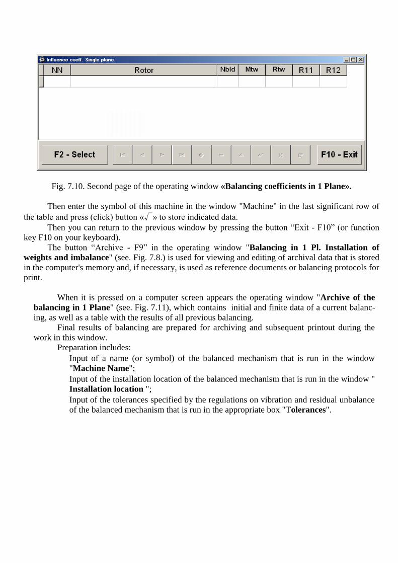
Fig. 7.10. Second page of the operating window «Balancing coefficients in 1 Plane».
Then enter the symbol of this machine in the window "Machine" in the last significant row of
the table and press (click) button «√» to store indicated data.
Then you can return to the previous window by pressing the button “Exit - F10” (or function
key F10 on your keyboard).
The button “Archive - F9” in the operating window "Balancing in 1 Pl. Installation of
weights and imbalance" (see. Fig. 7.8.) is used for viewing and editing of archival data that is stored
in the computer's memory and, if necessary, is used as reference documents or balancing protocols for
print.
When it is pressed on a computer screen appears the operating window "Archive of the
balancing in 1 Plane" (see. Fig. 7.11), which contains initial and finite data of a current balanc-
ing, as well as a table with the results of all previous balancing.
Final results of balancing are prepared for archiving and subsequent printout during the
work in this window.
Preparation includes:
Input of a name (or symbol) of the balanced mechanism that is run in the window
"Machine Name";
Input of the installation location of the balanced mechanism that is run in the window "
Installation location ";
Input of the tolerances specified by the regulations on vibration and residual unbalance
of the balanced mechanism that is run in the appropriate box "Tolerances".

Fig. 7.11. Operating window «Archive of the balancing in 1 Plane»
After input of the specified data for its storing in computer memory it is necessary to press (to
click) the button « √ » located among the operating buttons of the working window "Archive of
Balancing in 1 Plane".
After that, having pressed (clicked) the button “Protocol-F9”, it is possible to bring the draft
of the check protocol (fig. 7.12) to the computer display to edit it and, if necessary, to print or keep in
the computer memory as the text document.
To complete the work in this window press (click) the button “F10 – Exit”

Fig. 7.12. Balancing report.

7.4.2. Re-balancing in 1 Plane.
7.4.2.1. Setting the measuring system (input raw data).
Re-balancing can be performed on the machine for which balancing factors have already been identi-
fied and recorded in the computer memory.
Attention!
During the re-balancing the vibration sensor and the phase angle sensor must be installed in the
same way as during the initial balancing.
Input of the initial data for the re-balancing (as in case of the initial balancing) starts in the
operating window "Balancing in 1 Pl. Initial data" (see. Fig. 7.5.).
In section "Type of Balancing" use mouse to put a label in the "Re-balancing" and click but-
ton "Select" located to the right.
In this case, the computer shows the second page of the operating window " Balancing coef-
ficients in 1 Plane" (see. Fig. 7.10), in which the archive of the earlier specifed balancing factors is
stored.
Moving on the archive table via the control buttons «►» or «◄» you can select the desired
entry with coefficients of the balancing machine of interest. In case this data is used in the current
measurements click “F2 – Select” and return to the previous operating window "Balancing in 1 Pl.
Initial data" (see. Fig. 7.5.) by pressing «F10 - Exit ".
The contents of all other windows of the operating window "Balancing in 1 Pl. Initial data"
are filled in automatically.
Attention!
If necessary, the original data stored in the sections of the windows "Coordinate system" and
"Test weight installation radius" can be changed.
After completion of input of raw data click button “F9-Continue” (or press the F9 key on the
computer keyboard). Then on the display appears an operating window (see fig. 7.6) used for performance of a cycle
of measurements at Re-balancing.
7.4.2.2. Measurements during the Re-balancing. "Re-balancing" demands carrying out only one adjusting start and, at least, one test start of
the balanced car.
Measurement of vibration on the first - adjusting start-up of the machine is carried out in the
operating window "Balancing in 1 Plane" (see fig. 7.6) in section "Start without Weight".
Attention!
Before you begin measuring enable rotor rotation of the machine (first start) and make sure that
it has entered the operating mode.
Readiness of the program for work in this section is indicated by dark green color of a back-
ground of the section and illumination of the “F8-Return” and “F9-Run” buttons located in the right.
Button “F8 – Return” (or function key F8) can be used to return to the previous active win-
dow.

For the measurement of vibration parameters in section “Start without weight” click button
“F9 – Run” (or press F9 on your keyboard) and then start vibration measurement and analysis of measurements, which, depending on the frequency of the rotor rotation can last from 2 to 10 seconds.
Upon successful completion of the measurement process in the appropriate windows under
"Start without weight" appear the results of measurement of rotor speed (Nrev), as well as the RMS
value of the component (Vo1) and phase (F1) of the vibration, which manifests itself on the speed of
the balancing rotor.
At the same time over the operating window "Balancing in 1 plane" appears operating window
"Balancing weights" (see. Fig. 7.8), which shows the results of calculation the parameters of addi-
tional correction weight that must be installed (deleted) on the rotor to compensate its residual unbal-
ance.
Moreover, in case of using the polar coordinate system the display shows the value of mass
(M1) and angle of installation (f1) of the correction weight.
In case of the expansion of correction weights on the blades display shows the number of
blades of the balanced rotor and weight of weights that need to be installed at them.
Further, the balancing process is carried out in accordance with the recommendations set forth
in section 7.4.1.2. Primary balancing.
7.5. Balancing in two planes (dynamic balancing). Before working in the "Balancing in 2 plane" mode install vibration sensors on the machine in
the selected measurement points and connect respectively to the inputs X1 and X2 of the USB inter-face unit.
Photoelectric phase angle sensor should be connected to the input X3 of the USB interface unit. Besides, for use of this sensor it is necessary to apply the special tag having the reflecting ability on an available surface of a rotor of the machine which should be contrasting to the reflecting ability of a surface of a rotor.
Detailed requirements on site selection of the sensors and their attachment to the object when
“BALKOM-1” out in Annex 1.
As in case of balancing in the 1 plane, work on the program in the "Balancing in 2 plane" mode
starts from the main operating window.
For this purpose click the “F3-two-plane” button (or press the F3 key on the computer key-
board).
Mimic diagram shown in Fig. 7.2 confirms the selection “Balancing in one plane” mode and
illustrates the process of measuring of the vibration amplitude and phase on the first and second
measurement channels.
Further in the Main operating window of the program click on the “F7-Balancing” button, then
on the display appears an operating window (see fig. 7.13) used for input of initial data when balanc-
ing.
Select in this window one of the balancing options - "Primary" or "Re-balancing".
"Primary" is usually performed for the rotors of the balancing machines that have not been
balanced and for which there is no computer information in the archival memory needed to perform
"Re-balancing" (numerical values of balancing coefficients and mass of the test weight).
"Primary" balancing in 2 planes demands three starts of the machine required for calibration
of the measuring system of the device.
During the initial start the initial vibration of the machine is determined. The second start of
the machine is carried out after installing test weight on the rotor in the first balancing plane.

The third machine start is carried out after installing test weight on the rotor in the second
balancing plane.
"Re-balancing" is performed only for previously balanced machine for which mass of the test
weight and balancing factors are defined and stored in the memory. In this case, only one start of the
balanced machine rotor is required to determine the mass and siting of correction weights needed to
compensate for the imbalance.
Fig. 7.13. Operating window for raw data input when balancing in two planes.

7.5.1. Initial balancing in 2 Planes.
7.5.1.1. Setting the measuring system (input initial data). Input of initial data for primary balancing starts at the operating window "Balancing in 2 Pl. In-
itial data"(see. Fig. 7.13.).
In section "Type of Balancing" use mouse to put a label in the "Primary".
Next, in the "Mass of the test weight" you should select weight unit of the test weight, put a
label respectively in the column "Grams" and "Percent".
If you select a unit of measure "Percent" all further calculations of the correction weight mass
will be carried out as a percentage by weight of the test weight. If you select a unit of measurement "Grams" all further calculations of the correction weight
mass will be performed in grams. Then enter in the window located to the right of "Grams" mass of
the test weight, which will be installed on the rotor.
Attention!
If you require further work in the "Re-balancing" mode in the primary balancing masses of the
test weight must necessarily be entered in grams.
Next, in the "Coordinate System" it is necessary to choose one of possible options of place-
ment of the correction weights on the balanced rotor – in "Polar" or "Bladed" coordinate system.
Use mouse to put the check mark next to the appropriate caption.
If you select placing weights on blades of the driving wheel of the balanced car it is necessary
to enter rotor blades number in the corresponding window close to an inscription "Bladed".
Moreover, in the next section of the operating window, it is desirable to enter the installation
radius of trial weight, allowing to obtain additional information about the magnitude of the residual
unbalance of the rotor "g * mm".
After completion of the input of the initial data click on the button “F9 – Continue” (or press
F9 on your keyboard).
After that, the computer displays the operating window (see. Fig. 7.14) used to perform a com-
plete cycle of measurements when balancing.
7.5.1.2. Measurements during balancing. "Primary" balancing requires two calibration starts and at least one test start of a balancing
machine.
Measurement of vibrations at the first start-up of the machine is carried out in the operating
window "Balancing in 2 planes" (see. Fig. 7.14) in "Start without weight".
Attention!
Before starting the measurement it is necessary to include the balanced machine rotor (first
start) and make sure it started operation with stable speed.
The readiness of the program to work in this section is indicated by a dark green background
color section and button illumination “F8 – Return” and “F9 – perform” located in the right-hand
side.
Button “F8 – Return” (or function key F8) can be used to return to the previous operating
window.
For the measurement of vibration parameters in section “Start without weight” click button “F9 – Run” (or press F9 on your keyboard) and then start vibration measurement and analysis of
measurements, which, depending on the frequency of the rotor rotation can last from 4 to 15 seconds.

Upon successful completion of the measurement process in the appropriate windows under
"Start without weight" appear the results of measurement of rotor speed (Nrev), as well as the RMS
value of the component (Vо1, Vо2) and phase (F1, F2) of the vibration, which manifests itself on the
speed of the balancing rotor.
Thus color of a background of the section "Weight in the Plane 1" also changes (salad to dark
green) and illumination of the “F8-Return” and “F9-Run” buttons switches on that points to readiness
of the device for work on the second start.
Attention!
In case there is no signal during the measurement of the phase angle sensor (sensor is not con-
nected to the instrument or damaged), or when the rotational speed of the rotor is less than 300
rev / min, the warning banner (see. Fig. 7.7) is displayed on the computer display, indicating that
the actual speed of the rotor is outside measurements.
After fixing the problem press (click) "OK" button on the banner to continue work on the pro-
gram.
Fig. 7.14. Operating window used for balancing measurements in two plane.
Before starting the measurement of vibration parameters in the "Weight in the Plane 1" you should stop the rotation of the rotor of the balanced machine and install it on the test weight. The
mass of this weight, is either already set in preparation for the measurements in the memory of the device in the operating window "Balancing in 2 Pl. Initial data" (see. Fig. 7.13), or conditionally
admitted to the further calculations as 100%. You must then re-enable the balanced machine rotors and make sure that the machine has en-
tered the operating mode.
Attention!

1. The choice of the mass of the test weight and installation position on the balanced machine ro-
tor is particularly discussed in Annex 1.
2. If you require further work with the "Re-balancing" mode the place of installation of the test
weight must necessarily coincide with the plane set of the mark used for the phase angle refer-
ence.Внимание!
For the measurement of vibration parameters in the "Weight in Plane 1" click button “F9 – Run” (or press F9 on your keyboard) and then vibration measurement and analysis of measurements
start, which, depending on the frequency of the rotor rotation can last from 4 to 15 seconds.
Upon successful completion of the measurement process in the appropriate windows appear
the results of measurement of rotor speed (Nrev), as well as the RMS value of the component (Vо1,
Vо2) and phase (F1, F2) of the 1x vibration componentof the vibration.
Thus color of a background of the section "Weight in the Plane 1" also changes (salad to dark
green) and illumination of the “F8-Return” and “F9-Run” buttons switches on that points to readi-
ness of the device for work on the second start.
Before starting the measurement of vibration parameters in the "Weight in the plane 2" it is
necessary to stop the rotation of the rotor of the balanced machine and set the test weight in the plane
2. The mass of this weight, is either already set in preparation for the measurements in the memory of
the device in the operating window "Balancing in 2 Planes. Initial data" (see. Fig. 7.13), or
conditionally admitted to the further calculations as 100%.
You must then re-enable the balanced machine rotors and make sure that the machine has en-
tered the operating mode. For the measurement of vibration parameters in the "Weight in Plane 2" click button “F9 –
Run” (or press F9 on your keyboard) and then vibration measurement and analysis of measurements
start, which, depending on the frequency of the rotor rotation can last from 4 to 15 seconds.
Upon successful completion of the measurement process in the appropriate windows "Weight in Plane 2" appear the results of measurement of rotor speed (Nrev), as well as the RMS value of the
component (Vо1, Vо2) and phase (F1, F2) of the 1x vibration componentof the vibration.
Also the operating window "Checking" changes the background color (salad to dark green)
and switches on the backlight of the buttons “F8-Return” and “F9-Run”, which indicates the readi-
ness of the device to work on the second start.
At the same time over the operating window "Balancing in 2 planes" appears operating win-dow "Balancing weights" (see. Fig. 7.15), which shows the results of calculating the parameters of
the adjustment cost, which should be installed on the rotor to compensate its imbalance.
Moreover, in case of using the polar coordinate system the display shows the value of the mass
(М1, М2) and the angle of installation (f1, f2) of the correction weight.
In case of the expansion of correction weights on the blades display shows the number of
blades (Z1i, Z1j and Z2i, Z2j) of the balanced rotor and weight of weights that need to be installed at
them.

Fig. 7.15. Operating window with the results of the calculation of the correction weight parameters
Attention!:
1. After completion of the measurement process after the second start of the balanced machine stop
the rotation of its rotor and remove the previously set test weight. Only then you can begin to install
(or remove) correction weight on the rotor.
2. Counting the angular position of the place of adding (or removing) of the correction weight from
the rotor is carried out on the installation site of trial weight in the polar coordinate system. Count-
ing direction coincides with the direction of the angle of rotor rotation.
3. In case of balancing on the blades - the balanced rotor blade, conditionally accepted for the 1st,
coincides with the place of the test weight installation. Reference number direction of the blade
shown on the computer display is performed in the direction of the rotor rotation.
4. In this version of the program it is accepted by default that correction weight will be added on
the rotor. The tag established in the field "Addition" testifies to it.
In case of correction of imbalance by removal of a weight (for example by drilling) it is necessary
to establish tag in the field "Removal" then the angular position of the correction weight will change
automatically on 180 º.
Once installed on the balanced rotor correction weight press the button, “Exit -F10” (or func-
tion key F10 on the keyboard), return to the previous active window "Balancing in 2 planes" and as-
sess the effectiveness of the balancing operation implementation.

In this case, the operating window of the "Balancing in 1 plane" changes the background color of the
section "Checking" (salad to dark green) and switches on the backlight of the button “F9-Run”, which
indicates the readiness of the device to work on the fourth (test) start.
Attention!
Before you begin measuring on the fourth start enable rotor rotation of the machine and make
sure that it has entered the operating mode.
After completion of the test start measurements of rotor speed (Nrev) and RMS values (Vо1,
Vо2) and reverse-phase component of the vibration (F1, F2) obtained after balancing, are displayed
on a computer screen in the appropriate windows in this section.
At the same time over the operating window "Balancing in 2 planes" appears operating win-
dow "Balancing weights" (see. Fig. 7.15), which shows the results of calculation the parameters of
additional correction weight that must be installed on the rotor to compensate its residual unbalance.
Also the same window shows the residual unbalance of the rotor reached after balancing. If the value of the residual vibration and / or the residual unbalance of the balanced rotor
meets the tolerances specified in the technical specifications, the balancing process can be complet-
ed.
Otherwise, the balancing process can be continued. This allows using the method of successive
approximations to correct any errors that may occur during the installation (removal) of the correction
weight on the balanced rotor. At continuation of the balancing process it is necessary to install (remove) additional correc-
tive weight on the balanced rotor, parameters of which are shown in the operating window "Balanc-
ing weights".
After that you need to click the button "Exit - F10» (or a function key F10 on your keyboard)
and return to the previous active window to continue.
As it can be seen from Fig. 7.15, with an operating window "Balancing weights" in addition
to the button “Exit -F10” two other control buttons can be used – “Coefficients - F8”, «Archive -
F9».
Button “Coefficients - F8” (or function key F8 on the computer keyboard) is used for viewing and storing in memory rotor balancing coefficients, calculated from the results of the two calibration starts.
When it is pressed on a computer screen appears the operating window "Balancing coeffi-
cients in 2 Planes" (see. Fig. 7.16), showing balancing coefficients, calculated from the first three
calibration starts.
If a subsequent balancing of the machine will be used with the mode "Re-balancing", these coefficients must be stored in a computer memory.
For this purpose it is necessary to press the button “Save-F9” and to go to the second page of
the "Balancing coefficients in 1 Plane" windows (see Fig. 7.10).

Fig. 7.16. “Balancing coefficients in 2 Planes” operating window.
If a subsequent balancing of the machine will be used with the mode "Re-balancing", these coefficients must be stored in a computer memory.
For this purpose it is necessary to press the button “Save-F9” and to go to the second page of
the "Balancing coefficients in 1 Plane" windows (see Fig. 7.17).
Then enter the symbol of this machine in the window "Machine" in the last significant row of
the table and press (click) button «√» to store indicated data.
Then you can return to the previous window by pressing the button “Exit - F10” (or function
key F10 on your keyboard).
The button “Archive - F9” in the operating window "Balancing in 2 Pl. Installation of
weights and imbalance" (see. Fig. 7.15.) is used for viewing and editing of archival data that is
stored in the computer's memory and, if necessary, is used as reference documents or balancing pro-
tocols for print.
When it is pressed on a computer screen appears the operating window "Archive of the
balancing in 2 Plane" (see. Fig. 7.18), which contains initial and finite data of a current balanc-
ing, as well as a table with the results of all previous balancing.
Final results of balancing are prepared for archiving and subsequent printout during the
work in this window.
Preparation includes:
Input of a name (or symbol) of the balanced mechanism that is run in the window
"Machine Name";
Input of the installation location of the balanced mechanism that is run in the window "
Installation location ";
Input of the tolerances specified by the regulations on vibration and residual unbalance of the bal-
anced mechanism that is run in the appropriate box "Tolerances".
Fig. 7.17. Second page of the operating window «Balancing coefficients in 2 Planes».
After input of the specified data for its storing in computer memory it is necessary to press (to
click) the button « √ » located among the operating buttons of the working window "Archive of
Balancing in 2 Planes".
After that, having pressed (clicked) the button “Protocol-F9”, it is possible to bring the draft
of the check protocol to the computer display to edit it and, if necessary, to print or keep in the com-
puter memory as the text document.
The specified document is similar to the protocol of balancing in one plane, given above in fig.
7.12.
To complete the work in this window press (click) the button “F10 – Exit”

Fig. 7.18. Operating window «Archive of the balancing in 1 Plane»
7.5.2. Re-balancing in 2 Planes.
7.5.2.1. Setting the measuring system (input raw data).
Re-balancing can be performed on the machine for which balancing factors have already been
identified and recorded in the computer memory.
Attention!
During the re-balancing the vibration sensor and the phase angle sensor must be installed in the
same way as during the initial balancing.
Input of the initial data for the re-balancing (as in case of the initial balancing) starts in the
operating window "Balancing in 2 Pl. Initial data" (see. Fig. 7.13.). In section "Type of Balancing" use mouse to put a label in the "Re-balancing" and click but-
ton "Select" located to the right.
In this case, the computer shows the second page of the operating window " Balancing coef-
ficients in 2 Planes" (see. Fig. 7.17), in which the archive of the earlier specified balancing factors
is stored.
Button storing the entered data

Moving on the archive table via the control buttons «►» or «◄» you can select the desired
entry with coefficients of the balancing machine of interest. In case this data is used in the current
measurements click “F2 – Select” and return to the previous operating window "Balancing in 2 Pl.
Initial data" (see. Fig. 7.13.) by pressing «F10 - Exit ".
The contents of all other windows of the operating window "Balancing in 1 Pl. Initial data"
are filled in automatically.
Attention!
If necessary, the original data stored in the sections of the windows "Coordinate system" and
"Test weight installation radius" can be changed.
After completion of input of raw data click button “F9-Continue” (or press the F9 key on the
computer keyboard). Then on the display appears an operating window (see fig. 7.14) used for performance of a cy-
cle of measurements at Re-balancing.
7.5.2.2. Measurements during the Re-balancing. "Re-balancing" demands carrying out only one adjusting start and, at least, one test start of
the balanced car.
Measurement of vibration on the first - adjusting start-up of the machine is carried out in the
operating window "Balancing in 2 Planes" (see fig. 7.14) in section "Start without Weight".
Attention!
Before you begin measuring enable rotor rotation of the machine (first start) and make sure that
it has entered the operating mode.
Readiness of the program for work in this section is indicated by dark green color of a back-
ground of the section and illumination of the “F8-Return” and “F9-Run” buttons located in the right.
Button “F8 – Return” (or function key F8) can be used to return to the previous active win-
dow. For the measurement of vibration parameters in section “Start without weight” click button
“F9 – Run” (or press F9 on your keyboard) and then start vibration measurement and analysis of measurements, which, depending on the frequency of the rotor rotation can last from 4 to 15 seconds.
Upon successful completion of the measurement process in the appropriate windows under
"Start without weight" appear the results of measurement of rotor speed (Nrev), as well as the RMS
value of the component (V1o, V2o) and phase (F1, F2) of the vibration, which manifests itself on
the speed of the balancing rotor.
At the same time over the operating window "Balancing in 2 planes" appears operating win-
dow "Balancing weights" (see. Fig. 7.15), which shows the results of calculation the parameters of
additional correction weight that must be installed on the rotor to compensate its residual unbalance.
Moreover, in case of using the polar coordinate system the display shows the value of mass
and angle of installation of the correction weight.
In case of the expansion of correction weights on the blades display shows the number of
blades of the balanced rotor and weight of weights that need to be installed at them.
Further, the balancing process is carried out in accordance with the recommendations set forth
in section 7.5.1.2. Primary balancing.


7.6. Charts mode
Working in the "Charts" mode begins from the Main operating window (see. Fig. 7.1) by
pressing “F8 – Charts”. Then opens a window "Measurement of vibration on two channels. Charts"
(see. Fig. 7.19).
Fig. 7.19. Operating window "Measurement of vibration on two channels. Charts".
While working in this mode it is possible to plot four versions of vibration chart.
The first version allows to get a timeline function of the total vibration (of vibration speed) on
the first and second measuring channels.
The second version allows you to get graphs of vibration (of vibration speed), which occurs
on rotation frequency and its higher harmonical components.
These graphs are obtained as a result of the synchronous filtering of the total vibration time
function.
The third version provides vibration charts with the results of the harmonical analysis.
The fourth version allows to get a vibration chart with the results of the spectrum analysis.

7.6.1. Charts of total vibration. To plot a total vibration chart in the operating window "Measurement of vibration on two
channels. Charts" it is necessary to select the operating mode "Total vibration" by clicking the ap-propriate button. Then set the measurement of vibration in the box "Duration, in seconds," by clicking on the button «▼» and select from the dropdown list the desired duration of the measurement process, which may be equal to 1, 5, 10, 15 or 20 seconds;
Upon readiness press (click) the “F9-Measure” button then the vibration measurement process
begins simultaneously on two channels.
After completion of the measurement process in the operating window appear charts of time
function of the total vibration of the first (red) and the second (green) channels (see. Fig. 7.20).
On these charts time is plotted on X-axis and the amplitude of the vibration speed (mm/sec) is
plotted on Y-axis.
Fig. 7.20. Operating window for the output of the time function of the total vibration charts
There are also marks (blue-coloured) in these graphs connecting charts of total vibration with
the rotation frequency of the rotor. In addition, each mark indicates beginning (end) of the next revo-
lution of the rotor.
In need of the scale change of the chart on X-axis the slider, pointed by an arrow on fig. 7.20,
can be used.

7.6.2. Charts of reverse vibration. To plot a reverse vibration chart in the operating window "Measurement of vibration on two
channels. Charts" (see Fig. 7.19) it is necessary to select the operating mode "Reverse vibration" by clicking the appropriate button.
Then appears operating window “Reverse vibration” (see Fig. 7.21).
Press (click) the “F9-Measure” button then the vibration measurement process begins simulta-
neously on two channels.
Fig. 7.21. Operating window for the output of the reverse vibration charts.
After completion of the measurement process and mathematical calculation of results (syn-
chronous filtering of the time function of the total vibration) on display in the main window on a
period equal to one revolution of the rotor appear charts of the reverse vibration on two channels.
In this case, a chart for the first channel is depicted in red and for the second channel in green.
On these charts angle of the rotor revolution is plotted (from mark to mark) on X-axis and the ampli-
tude of the vibration speed (mm/sec) is plotted on Y-axis.
In addition, in the upper part of the working window (to the right of the button “F9 – Meas-
ure”) numerical values of vibration measurements of both channels, similar to those we get in the
"Vibrometer" mode, are displayed.
In particular: RMS value of the total vibration (Vis, Vjs), the magnitude of RMS (Vio, Vjo)
and phase (Fi, Fj) of the 1st harmonical component of the reverse vibration and rotor speed (Nrev).

7.6.3. Vibration charts with the results of harmonical analysis.
To plot a chart with the results of harmonical analysis in the operating window "Measurement
of vibration on two channels. Charts" (see Fig. 7.19) it is necessary to select the operating mode "Harmonical analysis" by clicking the appropriate button.
Then appears an operating window for simultaneous output of charts of temporary function and of spectrum of vibration harmonical aspects whose period is equal or multiple to the rotor rota-
tion frequency (see Fig. 7.22).
Attention!
When operating in this mode it is necessary to use the phase angle sensor which synchronizes the
measurement process with the rotor frequency of the machines to which the sensor is set.
Fig. 7.22. Operating window for the output of the specrum of vibration harmonical aspects.
Then set the revolution number on which the measurement will be taken. Click the button «▼»
and select from the dropdown list desirable rotor revolution number, which may be equal to 1, 2, 4 or 8
rotor revolutions. Upon readiness press (click) the “F9-Measure” button then the vibration measurement process
begins simultaneously on two channels.
After completion of the measurement process in operating window (see Fig. 7.22) appear
charts of time function (higher chart) and specrum of vibration harmonical aspects (lower chart).
The number of harmonic components is plotted on X-axis and RMS of the vibration speed
(mm/sec) is plotted on Y-axis.

In this case, a chart for the first channel is depicted in red and for the second channel in green.
7.6.4. Charts of vibration with the results of spectral. To plot a chart with the results of narrow-band spectral in the operating window "Measurement
of vibration on two channels. Charts" (see Fig. 7.19) it is necessary to select the operating mode "Spectral" by clicking the appropriate button:
Then select in the arisen operating window “Spectral” frequency range in which the measure-
ment will be taken.
Then appears an operating window for simultaneous output of charts of temporary function and
of spectrum of vibration harmonical aspects whose period is equal or multiple to the rotor rotation
frequency (see Fig. 7.23).
Fig. 7.23. Operating window for the output of the specrum of vibration harmonical aspects.
Click the button «▼» and select from the dropdown list desirable rotor revolution number,
which may be equal to 64, 128, 320 or 640 Hz. When selecting the frequency range remember that in the range of 64 Hz band analysis is 0.5
Hz, in the range of 128 Hz - 1 Hz, in the range of 320 Hz - 2.5 Hz and in the range of 640 Hz - 5 Hz.
Upon readiness press (click) the “F9-Measure” button then the vibration measurement process
begins simultaneously on two channels.
After completion of the measurement process in operating window (see Fig. 7.23) appear
charts of time function (higher chart) and specrum of vibration (lower chart).
The vibration frequency is plotted on X-axis and RMS of the vibration speed (mm/sec) is plot-
ted on Y-axis.
In this case, a chart for the first channel is depicted in red and for the second channel in green.

8. GENERAL INSTRUCTIONS ON OPERATION AND MAINTENANCE OF THE DEVICE
8.1. Before work, perform an external inspection of the device. It is necessary to check:
- Configuration of the device in accordance with Section 3 "Device components and delivery
set";
- Absence of mechanical damage to the housing of USB interface unit, computer, cables, sen-
sors and other components;
- Absense of pollution and oxidation of the plug pins on the device and cables, and easiness of
their connection. 8.2. At operation of the device it is not recommended to turn it on in the production power supply
network in which unpredictable sharp electric shocks and power surge can lead to failures in operation
of the device, especially the computer.
In case of inability to ensure power supply of high quality it is recommended to use self-contained power supply from the computer's battery.
8.3. Climatic conditions of operation and storage of the device must meet the requirements
stated in par. 2.15 and par. 9.4 of this manual. 8.4. In operation, in order to ensure the normal performance of the device and keep it in good
condition routine maintenance work should be carried out.
Types and maintenance intervals are given in Table 8.1.
Table 8.1
Виды технического обслужи-
вания
Периодичность проведения Кто выполняет
1. Плановое техническое об-
служивание (ТО 1)
Ежемесячно оператор, работающий с при-
бором
2. Внеплановое техническое
обслуживание
По возникновению неисправ-
ности
оператор, работающий с при-
бором; представитель ООО
"Кинематика".
8.4.1. Routine maintenance work includes:
- External inspection of all units of the device;
- Removing dust and dirt from vibration sensors, connecting cables, connectors, USB interface
unit and computer;
- Flushing connectors and optical components (LED-photodiode) of the phase angle sensor
(cleaning and washing are carried out with soaked in ethyl alcohol gauze); - Rubbing cables (rubbing is performed with soaked in gasoline gauze);
8.4.2. Unscheduled maintenance is performed when a fault occurs. It includes work related to trou-bleshooting, replacement of defective component parts, and, if necessary, all work on par. 8.4.1.
8.4.3. List of supplies required for maintenance is shown in Table 8.2.

Table 8.2
№№
Наименование и обозначение
ГОСТ, ТУ Нормы расхода материалов
п.п. материалов Материала ТО1 ТО2
Итого в
год
1 Спирт этиловый ректифицирован-
ный технический
ГОСТ
18300-72
0,05 л - 0,6 л
2 Бензин Б-70 ГОСТ 1012-77 0,10 л - 1,20 л
3 Марля медицинская ГОСТ 9412-77 5 дм - 60 дм
9. RULES OF TRANSPORTATION AND STORAGE
9.1. For convenient transportation of the device, keep components and documentation within a
special bag or a suitcase.
9.2. It is necessary to store the device on a rack in a specially allotted place protected from mois-
ture and dust. Avoid putting other products on it or impact of mechanical weights.
9.3. Storage air temperature is allowed ranging from +4 to +45 °C, max relative humidity 90% at
a temperature of 30 °C.
10. DEVICE CHECKING
Checking of the device is made according to requirements of the Technique of checking of the
“BALKOM-1” “ “BALKOM-1”-4”.
Periodic checking of the device has to be carried out at least once for 2 years by representa-
tives of Federal agency for technical regulation and metrology.
11. Acceptance certificate
11.1. “BALKOM-1” « “BALKOM-1”-1» cert. № manufactured in accordance with the
technical requirements of КИН002.00.000ТУ and by results of acceptance tests it is recognized suit-
able for operation.
Release date __________________
Representative of manufacturer: (Signature)
_______________

12. PACKING CERTIFICATE
12.1. “BALKOM-1” « “BALKOM-1”-1» cert. № is packed by the manufacturer according to the technical specifications КИН002.00.000ТУ.
Package date _______________
Packaging made: _________________ (Signature)
Accepted a product after packing: _________________ (Signature)
13. MANUFACTURER’S GARANTUES
13.1. The manufacturer guarantees compliance of the Portable field balancer “BALKOM-1”to re-
quirements of specifications КИН001.00.000ТУ at observance by the consumer of the conditions and
rules established by operational (technical) documentation.
13.2. Warranty period of operation - 12 months since the date of acquisition of the device by the
Consumer.
13.3. In case of failure of the device by manufacturer's fault within the warranty period, the
warranty period is extended by the time taken to eliminate the identified defects, with recording in
the logbook.
13.4. Warranty repairs performed at: 190095, Russia, St. Petersburg, ul. Shkapina, d. 32-34,
LLC "Kinematics", tel. (812) 252-1325

14. Information about complaints
14.1. In case of failure of the device in operation or malfunction detected in the period of the
warranty, the Customer must send to the manufacturer the following data:
designation (name) of the product;
serial number;
date of issue and date of acquisition;
the nature of the defect (description of the problem).
14.2. All faults are recorded in subsection 14.3, and a brief description of the fault in Table 9.1.
14.3. Registration list of complaints

15. Information about responsible for the operation of the product Table 15.1
№ p. Position of re-
sponsible per-
son
Name of re-
sponsible per-
son
Number and date of the order Signature
Appointment Assignment
16. Accounting Problems during operation
Table 17.1
Date and time of
failure of the
product or its
components.
Mode of opera-
tion, the nature
of the weight
Character, ex-
ternals of fail-
ure
Cause of
Failure
Measures taken
to solve the
problem
Position, name
and signature of
the person re-
sponsible for the
elimination of
the fault
Time spent on
solving the
problem
17. Notes


ANNEX 1
BALANCING IN OPERATIONAL CONDITIONS
(Help)
П.1.1. Rotor balancing in one and two planes of correction.
The quantity of balancing planes is defined with design features of a rotor of the balanced car.
Balancing in one plane ("static") is usually carried out for the narrow disk-shaped rotors with
no essential axial beats.
Typical examples of rotors of this class are:
narrow grinding wheels;
pulleys of belt drives;
disk flywheels;
cogwheels;
couplings;
tightening cartridges of lathes;
narrow fans, etc.
Balancing in two planes ("dynamic") is carried out for long (arched) double-bearing rotors.
Typical examples of rotors of this class are:
rotors of electric motors and generators;
rotors for compressors and pumps;
turbine wheel and fans;
wide wheels;
spindles;
shafts of flour machines with whips, etc.
П.1.2. Features of the balanced machine installation.
As a rule, balancing of the machine is carried out directly on a place of its installation.
The exception takes place when the speed of a rotor gets to one of car resonance ranges. A sign
of it is the difference (more than for 10-20%) of results of amplitude and/or a phase measurements
from start to start. In case of a resonance identification it is necessary to change the speed of a rotor
rotation and in case it is impossible - to change conditions of car installation on the base (for example,
having it temporarily established on elastic support). Особенности установки балансируемой ма-
шины.
П.1.3. Choice of speed rotation of a rotor.
Balancing is usually set at operation speed of a rotor rotation. Балансировку обычно прово-
дят на рабочей скорости вращения ротора. In case when applies an actuator with speed change ability,
it is advisable to select the highest operation speed.
Attention!
At a choice of rotation speed of a rotor when balancing it is necessary to avoid hit in ranges of reso-
nances of the car (see Ann. Par. 1.2.)

П.1.4. Choice of measuring points and planes of correction.
Bearing supports or pole planes are preferably selected as vibration measurement points.
When balancing in a single plane it is sufficient to have one measuring point (see Fig. Ann.
1.1.).
Fig.P1.1. Choice of measuring points and planes of correction when balancing in one plane.
Fig. P.1.2. Сhoice of measurement points and the correction planes when balancing in two planes in case
of a symmetric rotor
Vibration measurement
point in Pl. 2 Vibration measure-
ment point in Pl. 1
Correction Plane 2 Correction Plane 1
Rotor Bearing
Bearing
Correction
plane (weighting) Vibration measurement point (mounting position)
Bearings Rotor

Fig. P.1.3. Choice of measurement points and correction planes when balancing in two planes in case of an
outboard rotor.
When balancing in two planes there should be two points of measurement (see. Fig. Ann. 1.2
and Ann. 1.3).
Correction planes, in which occurs the removal (setting) of correction weights on the rotor,
should be selected as close as possible to the point of measurement. In case of balancing in two
planes distance between the planes should be chosen as large as possible.
P.1.5. Choice of test weight weight.
Weight of the test weight may be approximately determined from the empirical formula:
Мр Мп = (P.1.1)
2
Rп*(N/100) where: Мп - test weight weight, g
Мр – balanced rotor weight, g Rп –test weight installation radius, sm
N – rotor speed, rpm
К= from 1 to 5 – coefficient considering conditions of installation of
the balanced rotor.
When the weight of test weight is correct its installation on the rotor should lead to noticeable
changes in the level of vibration. Otherwise, the weight of the test weight should be increased.
P.1.6. Features of sensors installation.
а) The vibration sensor may be installed at the measurement point using:
-Threaded rod (rigid attachment);
- Magnetic sucker;
- transitional probe (clip with a hand);
Correction Pl. 2
Vibration measure-
ment point in Pl. 1
Vibration meas-
urement point in Pl. 2
Correction Pl. 1
Rotor
Bearings

- direct contact of the sensor with a support
(clip with a hand).
b) Phase-angle sensor can be installed on the machine with special devices (e.g., magnetic rack
or clamp) and must be oriented on normal to the cylindrical or end surface of the rotor. Mark is ap-
plied with a chalk, light-reflecting tape or likewise on the surface of the rotor to reference the phase
angle. As a mark also be used the keyways, holes, protruding bolt heads, etc which are available on
specific rotors.
For production of the reflecting mark the adhesive mirror reflecting tape or the adhesive light-
reflecting tape are included in a dekivery set.
Light-reflecting tape is recommended to be used for severe conditions of the sensor operation (the raised gap, a flare external sources of light radiation).
The gap between the sensor and the rotating surface of the rotor for phase angle sensor of DT
2234C + type must be installed within 10 - 500 mm.
For phase angle sensors of other models, which can optionally be equipped with the device,
the allowable range of the operating clearance is set to meet the requirements of technical documen-
tation for the sensor. It must be understood that the choice of width of "L" mark depends on the rotation frequency
of a rotor and radius of mark installation. Approximately it can be calculated on a formula:
N * R
L ≥ ≥ 1 – 1.5 sm (P.1.2)
30000
where: L – mark width (min), sm
N – rotor speed, rpm
R – mark installation radius, sm
Based on the experience of practical application the recommended width of mark must be
min 1 - 1.5 cm.
For midget rotors with the mark installation radius of 10 mm it is recommended to use a nar-
rower label. It is desirable to conduct an experimental verification of correctness of the label width
choice.
Attention!
When using the photoelectric phase angle sensor in order to avoid interference, it is desirable to avoid
direct sunlight or strong artificial light reflecting on the mark and / or sensor (photodiode).

P.1.7. Criteria of balance according to the state standard ISO 10816-1-97 ( ISO
2372)
Limit values for vibration level established for the four classes of machines are listed in
Table P.1. Table P.1
*) Machine
class
Acceptable levels of vibration, mm/sec RMS
Good Acceptable Still acceptable Unacceptable
1 < 0.7 0.7 - 1.8 1.8 - 4.5 > 4.5
2 < 1.1 1.1 - 2.8 2.8 - 7.1 > 7.1
3 < 1.8 1.8 - 4.5 4.5 - 11 > 11
4 < 2.8 2.8 - 7.1 7.1 - 18 > 18
*)Note:
- Class 1 corresponds to small machines, installed on rigid foundations (analogue -
motors up to 15 kW);
- Class 2 corresponds to average machines, installed without separate foundations
(analogue - electric power of 15-75kvt), as well as actuators on detached foundations
with individual power up to 300 kW;
- Class 3 corresponds to large machines installed on rigid foundations (analogue - the
electrical equipment of more than 300 kW);
- Class 4 corresponds to large machines installed on foundations of facilitated type
(analog - electrical equipment more than 300 kW).