Embed Size (px)
Citation preview

The bi-metric XR™
series of Hip implants
blends biomet’s
proven philosophy
and tradition
with Advanced
technology
porous primary
hip series

Standard (SPP), Reduced (RPP) and CDH profile stems provide for an accurate fit in the proximal femur. The RPP stem is reduced medially 4mm from the SPP stem.
Reduced Tapered Trapezoidal Neck:A shorter Morse-type taper with a
trapezoidal neck geometry to reduce the risk of impingement.
Polished Neck Surface: Polished neck and shoulder geometry to help reduce the amount of wear on the implant surface.
Clinically Proven PPS® Porous Plasma Spray Coating:2–4
A titanium alloy substrate combined with non-interconnected, circumferential titanium porous coating has been designed for bony ingrowth to lock in the femoral implant and create a seal to particulate debris migration that may help to reduce osteolysis and improve long-term fixation.8
RPP
SPP
CDH*
BI-METRIC XR™ SERIES implant technology
The Bi-Metric XR™ Hip Series has been designed to meet the demands of today’s active patient. The XR Series is a fusion of sound engineering principals and surgical expertise, utilizing modern manufacturing and implant design technologies.
Standard Bi-Metric® Stem
Bi-Metric XR™ Stem
*CDH neck not shown in this photo illustration.

Interlok® Surface:Provides a roughened titanium surface for bone ongrowth, enhancing the potential for long-term fixation.
Titanium:All Bi-Metric XR™ Stems are constructed of Ti-6Al-4V titanium alloy to enhance bio-compatibility, high fatigue strength and a low modulus of elasticity.
Bi-Planar Tapered Stem:Biomet’s philosophy incorporates a clinically proven 3° bi-planar taper geometry. The stem tapers 3° from the proximal shoulder to the distal tip of the implant and from the lateral shoulder to the medial calcar area. The taper affords greater proximal stress off-loading and minimizes the need to remove distal cortical bone. Each implant’s distinct lateral-to-medial taper is designed to provide physiologic proximal load transfer and exceptional implant-to-patient fit.
Increased lateral offset is provided by an option of either a 131.5º or 126.5º neck angle, allowing accurate matching of patient anatomy and improved tissue tension and leg length restoration.
131.5º
126.5º
Trapezoidal neck geometry reduces the risk of impingement and provides for an increased range of motion up to 145º using the M2a-Taper™ 32mm articulation.

Primary Results at 10–12 year follow-up/ 100% survivorship in 105 hips16 • No Osteolysis• HHS Increased from an Average of 26
Preoperatively to 92 Postoperatively• No Revisions
8–11 year follow-up / 100% AsepticSurvivorship in 67 hips10 • 3% Thigh Pain• 1.5% Osteolysis• No Revisions for Aseptic Loosening
5–15 year follow-up of 118 hips6 • No Osteolysis• No Thigh Pain• 100% Survivorship
unCoMpRoMISEd TRAdITIon And TECHnology
The foundation for the XR Series of implants is the excellent long-term clinical results
of proximal-to-distal tapered stem geometries (Figure 1). The 3º bi-planer taper provides
physiologic proximal load transfer and preserves distal cortical bone, significantly reducing
the likelihood of proximal resorbtion. The Bi-Metric XR™ family of femoral components
uses net-shape forgings and advanced manufacturing technology to optimize the consistency
of multiple geometries and configurations. The combined technology and geometries have
proven to meet the needs of both the patient and the surgeon for successful cementless
hip reconstruction.
Meticulous design and superior materials, combined with improved manufacturing
techniques, have allowed for advanced concepts in femoral components and instrumentation.
Net-shape forging technology results in a consistent and reproducible surgical technique.
This advanced net-forging technology provides a more precise envelope for the implant,
which has greatly reduced the “human variability,” or hand polishing, associated with
previous manufacturing methods. This technology allows for superior reproduction of the
compound angles on the finished implants and has been integral in the development of the
highest standards of performance. In addition, net-forgings adhere to the industry’s most
exacting dimension tolerances, which provide a more consistent broach-to-implant fit. The
XR Series implants maximize the effectiveness of net-forging technology while maintaining
the specific features that surgeons prefer.
the XR Series of hip
implants is built on the
design and long term
clinical success of the
Bi-metric® Stem
BI-METRIC XR™ SERIES implant technology
Figure 1 – The Bi-Metric® Porous Hip System is the foundation of the technologically advanced Bi-Metric XR™ Series Femoral Components.
2

3
ToTAl SySTEM AppRoACHOffering a wide range of stem diameters, the Bi-Metric XR™ femoral
components can be combined with all of the Biomet® Articulation and
Acetabular designs making the XR Series one of the most versatile and
comprehensive systems available today.
EXACT™ HIp InSTRuMEnTATIon
Simple Standard Instrument Sets: Incorporating one common set
of instruments, the Exact™ hip instruments are used to implant all
Bi-Metric XR™ Series components (Figure 1). This feature provides
the surgeon with maximum flexibility and simplifies procedures for the
OR staff while reducing instrument inventory for the hospital.
BIoMET innovations:
• TITAnIuM
• BI-plAnAR TApER gEoMETRy
• CIRCuMFEREnTIAl plASMA SpRAy
poRouS CoATIng
Figure 1 – Exact™ General Instrument Case #1

BI-METRIC XR™ SERIES implant technology
TITAnIuM ppS® poRouS plASMA SpRAy
Plasma spray is a three-dimensional distribution of
randomly dispersed titanium particles (Figure 1).
Biomet’s proprietary plasma spray application is unique
in that only the titanium alloy powder used to create
the coating is heated, not the implant’s substrate
(Figure 2). Plasma spray porous coating is applied to
the substrate of the implant at a low temperature,
which preserves up to 90% of the mechanical strength
of the implant.2 Randomly shaped particles are flattened upon impact with the substrate. An
arbitrary distribution of pore size between 100 and 1,000 microns is generated, providing a
larger contact area between the particles and the substrate (Figure 3). The resulting surface
is rough in contrast to the smooth surfaces of a beaded implant. Implant stability, interface
strength and contact to the bony surface area are maximized by the irregular surface. This
feature allows the implant to scrape bone into the pores during implantation, providing
solid initial fixation. In addition, the random particle dimensions result in a varied pore size
distribution. Smaller pores are important for initial fixation because they can fill in with bone
more quickly to help promote early osseointegration. Larger pores require a longer time to fill
in and provide for long-term fixation with continued macro bone in-growth. Bony in-growth is
important for mechanical interlocking and maximum load transfer. Studies show that “rough
titanium has been found to have a good propensity for adhesion of osteoblasts.”17
Circumferentially coating the femoral component with plasma spray creates a barrier
to particulate debris (metallic, polyethylene or PMMA), which can trigger a macrophage
response that can initiate osteolysis.1,5,9,14 Tanzer, et al., have reported that sealing the
endosteum from the pumping of debris may be the most important factor in preventing
osteolysis in total hip patients.18 The lack of longitudinal pore interconnectivity creates a seal
from this particulate debris migration, which may help to reduce osteolysis and improve
long-term fixation.7,18 While other femoral components have circumferential porous coating,
it is not Biomet’s clinically proven non-interconnected plasma spray.3,7,13
The Bi-Metric XR™ Series implants offer a variety of surface finishes that promote
fixation. Biomet’s porous plasma sprayed components have shown significantly lower rates of
osteolysis than other circumferentially-coated components.8,11,12,15,16
Proximal circumferential non-interconnected plasma spray works in conjunction with the
implant design for optimal bone ingrowth. A roughened Interlok® finish distally provides the
medium for bone ongrowth which is consistent with proximal fixation.
0
10
20
30
40
50
60
70
80
Sintered or Diffusion Bonded
Plasma Sprayed
Sintered or Diffusion Bonded
Plasma Sprayed
Ti Alloy Co-Cr Alloy
Fatig
ue S
treng
th (k
si) at
107 C
ycles
Range of values determinedRange of values reported
Effect of the porous coating method on fatigue strength.8
Figure 1 – Above is an SEM photograph at 100x magnification showing PPS® plasma spray porous coating.
4
Figure 2 – Titanium PPS® Porous Plasma Spray being applied through a heated plasma arc.
Substrate
Most pores are small
Mixture of large & small pores
Most pores are large, but a few are small for initial fixation
Figure 3

oFFSET RESToRATIonIn total hip reconstruction, the most effective and easily manipulated
mechanical variable available to the surgeon to optimize the biomechanics of
the hip is the offset of the prosthesis. Having the ability to change the offset
allows the surgeon to increase joint stability and restore normal hip function.
If the potential offset deficiency is not identified or treated, it could lead to
joint instability, limp, and increased joint reaction forces. The advantage,
intraoperatively, is that it allows for adjustment of offset and soft tissue
tension without changing the neck resection level or the length of the leg.
In-depth studies have concluded that femurs with greater horizontal offset
often have a more varus neck shaft angle. As the stem size increases, the
required offset also increases.4 The Bi-Metric XR™ component’s design is
based on this philosophy.
The Bi-Metric XR™ Series implants employ two different femoral neck
angles to achieve optimal offset restoration. The standard proximal profile
stems (SPP) utilize a 131.5º neck angle and the reduced proximal profile
stems (RPP) offer both a 131.5º and 126.5º neck shaft angle to increase
offset (Figure 1). These neck angle options combined with seven modular
head neck length choices work in unison to promote gradual off-loading of
stresses from the femoral component throughout the entire femur.
5
Femoral Offset
Figure 1: Comparison of head location for XR series RPP stems: Computer model illustrates the +3mm head position on the 126.5º stem is lateralized 4mm from the standard head position on the 131.5º stem. The 126.5º stem with a +3mm head and the 131.5º stem with a standard head have the same vertical offset.
131.5º126.5º
4mm0mm
3mm
anatomic offsets
enhance joint
stability and help
restore hip
biomechanics by
providing the
opportunity to tighten
soft tissue without
creating leg length
discrepancies
RPP
131.5º126.5º
4mm0mm
3mm

offset information
6
ImplantPart No.
Size(mm)
Stem Length(mm)
Neck Angle(Degrees)
Neck LengthStd Head
Horizontal OffsetStd Head
Vertical OffsetStd Head
X180437 7 115 131.5 32.0 38.4 25.7X180438 8 120 131.5 32.0 38.7 25.8X180439 9 125 131.5 32.0 38.9 25.9X180440 10 130 131.5 32.0 39.2 26.0X180441 11 135 131.5 32.0 39.6 26.2X180442 12 140 131.5 32.0 39.9 26.3X180443 13 145 131.5 32.0 40.2 26.4X180444 14 150 131.5 32.0 40.5 26.5X180445 15 155 131.5 32.0 40.7 26.7X180446 16 160 131.5 32.0 41.1 26.8
ImplantPart No.
Size(mm)
Stem Length(mm)
Neck Angle(Degrees)
Neck LengthStd Head
Horizontal OffsetStd Head
Vertical OffsetStd Head
X180407 7 115 131.5 32.0 38.4 27.8X180408 8 120 131.5 32.0 38.7 27.9X180409 9 125 131.5 32.0 39.0 28.0X180410 10 130 131.5 32.0 39.3 28.1X180411 11 135 131.5 32.0 39.6 28.3X180412 12 140 131.5 32.0 39.9 28.4X180413 13 145 131.5 32.0 40.2 28.6X180414 14 150 131.5 32.0 40.5 28.7X180415 15 155 131.5 32.0 40.7 28.8
BI-METRIC XR™ SERIES 131.5º REduCEd pRoXIMAl pRoFIlE (Rpp)
BI-METRIC XR™ SERIES 131.5º STAndARd pRoXIMAl pRoFIlE (Spp)
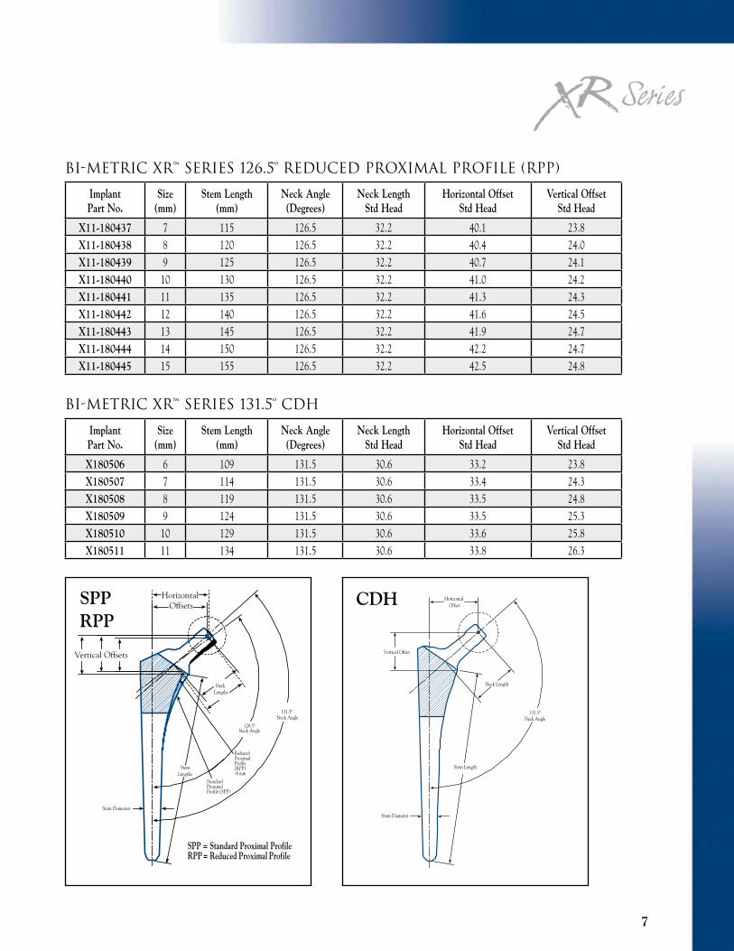
7
ReducedProximalProfile (RPP)-4 mm
SPP = Standard Proximal ProfileRPP = Reduced Proximal Profile
Vertical Offsets
Neck Angle
Neck Lengths
Horizontal Offsets
Stem Diameters
131.5º
126.5ºNeck Angle
StandardProximalProfile (SPP)
StemLengths
SPP RPP
ImplantPart No.
Size(mm)
Stem Length(mm)
Neck Angle(Degrees)
Neck LengthStd Head
Horizontal OffsetStd Head
Vertical OffsetStd Head
X11-180437 7 115 126.5 32.2 40.1 23.8X11-180438 8 120 126.5 32.2 40.4 24.0X11-180439 9 125 126.5 32.2 40.7 24.1X11-180440 10 130 126.5 32.2 41.0 24.2X11-180441 11 135 126.5 32.2 41.3 24.3X11-180442 12 140 126.5 32.2 41.6 24.5X11-180443 13 145 126.5 32.2 41.9 24.7X11-180444 14 150 126.5 32.2 42.2 24.7X11-180445 15 155 126.5 32.2 42.5 24.8
ImplantPart No.
Size(mm)
Stem Length(mm)
Neck Angle(Degrees)
Neck LengthStd Head
Horizontal OffsetStd Head
Vertical OffsetStd Head
X180506 6 109 131.5 30.6 33.2 23.8X180507 7 114 131.5 30.6 33.4 24.3X180508 8 119 131.5 30.6 33.5 24.8X180509 9 124 131.5 30.6 33.5 25.3X180510 10 129 131.5 30.6 33.6 25.8X180511 11 134 131.5 30.6 33.8 26.3
BI-METRIC XR™ SERIES 131.5º CdH
BI-METRIC XR™ SERIES 126.5º REduCEd pRoXIMAl pRoFIlE (Rpp)
131.5ºNeck Angle
Neck Length
Stem Length
Stem Diameter
Vertical Offset
HorizontalOffsetCDH

8
implant and Instrument ordering information
ImplantPart No.
Size(mm)
Stem Length(mm)
Broach Part No.
Trunion Part No.
X180437 7 115 31-400107 X31-400210X180438 8 120 31-400108 X31-400210X180439 9 125 31-400109 X31-400210X180440 10 130 31-400110 X31-400210X180441 11 135 31-400111 X31-400211X180442 12 140 31-400112 X31-400211X180443 13 145 31-400113 X31-400211X180444 14 150 31-400114 X31-400211X180445 15 155 31-400115 X31-400212X180446 16 160 31-400116 X31-400212
BI-METRIC XR™ SERIES 131.5º REduCEd pRoXIMAl pRoFIlE (Rpp)
BI-METRIC XR™ SERIES 131.5º STAndARd pRoXIMAl pRoFIlE (Spp)
ImplantPart No.
Size(mm)
Stem Length(mm)
Broach Part No.
Trunion Part No.
X180407 7 115 X31-400007 X31-400200X180408 8 120 X31-400008 X31-400200X180409 9 125 X31-400009 X31-400200X180410 10 130 X31-400010 X31-400200X180411 11 135 X31-400011 X31-400201X180412 12 140 X31-400012 X31-400201X180413 13 145 X31-400013 X31-400201X180414 14 150 X31-400014 X31-400201X180415 15 155 X31-400015 X31-400202
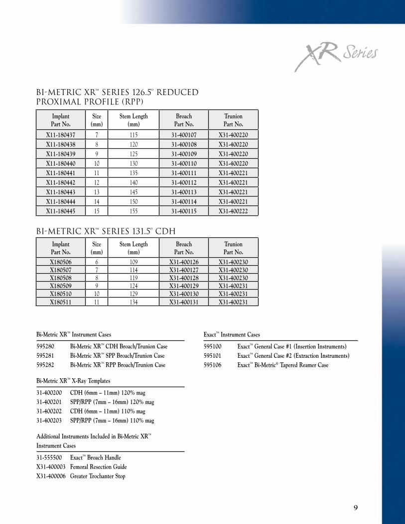
Bi-Metric XR™ Instrument Cases
595280 Bi-Metric XR™ CDH Broach/Trunion Case595281 Bi-Metric XR™ SPP Broach/Trunion Case595282 Bi-Metric XR™ RPP Broach/Trunion Case
Bi-Metric XR™ X-Ray Templates
31-400200 CDH (6mm – 11mm) 120% mag31-400201 SPP/RPP (7mm – 16mm) 120% mag31-400202 CDH (6mm – 11mm) 110% mag31-400203 SPP/RPP (7mm – 16mm) 110% mag
Additional Instruments Included in Bi-Metric XR™ Instrument Cases
31-555500 Exact™ Broach HandleX31-400003 Femoral Resection GuideX31-400006 Greater Trochanter Stop
9
Exact™ Instrument Cases
595100 Exact™ General Case #1 (Insertion Instruments)595101 Exact™ General Case #2 (Extraction Instruments)595106 Exact™ Bi-Metric® Tapered Reamer Case
ImplantPart No.
Size(mm)
Stem Length(mm)
Broach Part No.
Trunion Part No.
X11-180437 7 115 31-400107 X31-400220X11-180438 8 120 31-400108 X31-400220X11-180439 9 125 31-400109 X31-400220X11-180440 10 130 31-400110 X31-400220X11-180441 11 135 31-400111 X31-400221X11-180442 12 140 31-400112 X31-400221X11-180443 13 145 31-400113 X31-400221X11-180444 14 150 31-400114 X31-400221X11-180445 15 155 31-400115 X31-400222
BI-METRIC XR™ SERIES 126.5º REduCEd pRoXIMAl pRoFIlE (Rpp)
ImplantPart No.
Size(mm)
Stem Length(mm)
Broach Part No.
Trunion Part No.
X180506 6 109 X31-400126 X31-400230X180507 7 114 X31-400127 X31-400230X180508 8 119 X31-400128 X31-400230X180509 9 124 X31-400129 X31-400231X180510 10 129 X31-400130 X31-400231X180511 11 134 X31-400131 X31-400231
BI-METRIC XR™ SERIES 131.5º CdH

REFEREnCES & AddITIonAl SuppoRT MATERIAl
1. Anthony, P.; et al.: “Localized Endosteal Bone Lysis in Relation to the Femoral Components of Cemented Total Hip Arthroplasties.” J. Bone Joint Surg., B: 971–979, November, 1990.
2. Bourne, R.B.; et al.: “Ingrowth Surfaces: Plasma Spray Coating to Titanium Alloy Hip Replacements.” CORR, 298: 37–46, 1994.
3. “Clinical Evaluation of Titanium Alloy Cementless Total Hip Replacement: A 1–5 Year Multi-Center Study.” Biomet, Inc., Clinical Report, 1994.
4. Davey, J.R.; Tozakoglou, E.: “The Role of Lateral Offset Stems.” Orthop. Trans., 22(1): 273, 1999.
5. DeHeer; et al.: “Differential Activation of Macrophages by Implant Wear Debris.” Trans. Implant Retrieval Symposium of the Society for Biomaterials, 85, 1992.
6. Evans, J.: “Outcome of a Tapered, Titanium, Proximal Load-Bearing Non-Cemented Femoral THA Component: A Minimum 5-Year Follow-Up Study.” Presented at AAOS, New Orleans, LA, March 19–23, 1998.
7. Head, W.C.: “Mallory-Head Porous Press-Fit Primary Hip Replacement.” Presented at the Tenth Annual International Symposium: New Developments in Total Joint Reconstruction, Lake Tahoe, Nevada, June 14–16, 1993.
8. Head, W.C.; Mallory, T.H.; Emerson Jr., R.H.: “The Proximal Porous Coating Alternative for Primary Total Hip Arthroplasty.” Orthop., 22: 813, 1999.
9. Horowitz, S.; et al.: “Microphage Exposure to Polymethyl Methacrylate Leads to Mediator Release and Injury.” J. Orthop. Research, 9(3): 406–413, 1991.
10. Jiranek, W.: “The Bi-Metric Component at 8–11 Years.” Presented at the ’ 98 Harvard Hip Course.
11. Keisu, K.; Orozco, F.; Sharkey, P.; Hozack, W.; Rothman, R.: “Primary Cementless Total Hip Arthroplasty in Octogenarians.” J. Bone Joint Surg., 83-A: 359, 2001.
12. Mallory, T.H.: “Minimum 10-Year Results of a Tapered Cementless Femoral Component in Total Hip Arthroplasty.” Presented at Festschrift Celebration, May 2001—to be published in J. Arthroplasty.
13. Mallory, T.H.; et al.: “Clinical and Radiographic Outcome of a Cementless Titanium Plasma-Spray Coated Total Hip Arthroplasty Femoral Component: Justification for Continuance of Use.” Presented at the Annual Meeting of the AAOS, Orlando, FL, February, 1995.
14. Maloney, W.; et al.: “Fibroblastic Response to Particulate Metallic Debris.” Trans. Implant Retrieval Symposium of the Society of Biomaterials, 34, 1992.
15. Mauerhan, D.R.; Mesa, J.; Gregory, A.; Mokris, J.: “Integral Porous Femoral Stem 5 to 8 Year Follow-up Study.” J. of Arthroplasty, 12(3): 250–255, 1997.
16. Meding, J.B.: “Minimum Ten-Year Follow-Up of a Straight-Stemmed, Plasma-Sprayed, Titanium-Alloy, Uncemented Femoral Component.” Presented at AAOS, San Francisco, CA, February 28 – March 4, 2001.
17. Symposium: “Porous Coating Methods: The Pro’s and Cons.” Contemporary Orthop., 27(3): 269–296, 1993.
18. Tanzer, M.; et al.: “The Progression of Femoral Cortical Osteolysis in Association with Total Hip Arthroplasty Without Cements.” J. Bone Joint Surg., 74-A: March, 1992.
M2a-Taper™, Bi-Metric®, Bi-Metric XR™, Exact™, PPS® and Interlok® are trademarks of Biomet Manufacturing Corp.
P.O. Box 587, Warsaw, IN 46581-0587 • 800.348.9500 ext. 1501©2006 Biomet Orthopedics, Inc. All Rights Reserved • www.biomet.com
Form No. Y-INT-091/051506/Japan
DrivenByEngineering
This material is intended for the sole use and benefit of the Biomet sales force and physicians. It is not to be redistributed, duplicated or disclosed without the express written consent of Biomet.
This brochure is intended for international use only. Some of the information contained herein may pertain to products, indications for use of products and/or therapies that are available only outside the United States of America and are not cleared or approved for marketing by the United States Food and Drug Administration.

126.5º Rpp
131.5º Rpp
131.5º Spp
131.5º CdH
The Bi-Metric XR™ Hip Series implants offer four distinctive design strategies for restoration of lateral offset.

KEy dESIgn FEATuRES:
• 3° Bi-planar taper provides enhanced proximal
stress off-loading and initial implant stability.
• Forged titanium for better biocompatibility and
a lower modulus of elasticity for enhanced
load transfer.
• Standard proximal profile (SPP), reduced
proximal profile (RPP) and CDH implant
geometries.
• Two neck angles of 131.5º and 126.5º accommodate more varus neck angles
and allow for lateralization and proper
joint restoration.
• Polished proximal geometry for reduced wear
on the neck.
• Reduced trapezoidal neck to increase range of
motion and reduce risk of impingement.
• Manufactured with state-of-the-art solid
modeling and net-shaped forgings.
• The titanium plasma spray porous coating’s
structure acts as a potential barrier to the
migration of particulate debris and provides
rotational stability and proven long-term
fixation.
• Seven neck lengths allow for accurate leg length
adjustment.
• Medialization of the insertion hole facilitates
implant insertion without interference of the
greater trochanter.
• Exact™ Instrumentation for
intraoperative flexibility.


![Appendix 1 HIP Male and Female - University of East Anglia · App14.1!HIP!v3.2_02_05_2012!!!!!Health’Improvement’Profile[HIP]’ ’’’’’’’’’’’’’’’’’’’’’’’’’’’’(HIP)–’Male](https://img.dokumen.tips/doc/110x75/5f0af26b7e708231d42e1f1c/appendix-1-hip-male-and-female-university-of-east-anglia-app141hipv3202052012healthaimprovementaprofilehipa.jpg)