Embed Size (px)
Citation preview

Copyright ©2016 Boeing. All rights reserved.
Polymeric Additive Manufacturing: Present
Status and Future Trends of Materials and
Processes
Antonio Paesano, Ph. D.
Abstract – The additive manufacturing (AM) industry is
predicted to maintain a strong growth rate over the next years,
and exceed $21 billion in sale of products and services by 2020,
also thanks to its capacity of innovating and developing
materials with better performance and broader range of
applications. This paper provides an overview of the polymers
currently used for AM, and the AM processes used with them.
It also describes the polymers most likely to be developed in the
short term, along with their future properties and process
requirements.
Index Terms – Additive manufacturing, development, fused
deposition modeling, innovation, laser sintering, material
jetting, multi jetting modeling, polymers, stereolithography.
I. INTRODUCTION
The ASTM F2792 defines additive manufacturing (AM)
as “a process of joining materials to make objects from 3D
model data, usually layer upon layer, as opposed to
subtractive manufacturing methodologies. Synonyms:
additive fabrication, additive processes, additive techniques,
additive layer manufacturing, layer manufacturing, and
freeform fabrication”. AM is also known as 3D printing.
Some parts made by using AM, or printed parts, are
pictured in Figure 1, where it is easy to appreciate the fine
details and high degree of complexity achievable, which
constitute some of AM’s strongest advantages.
Figure 1. Parts made from metal AM.
AM was officially born in 1986, when Charles Hull
patented an “apparatus for production of three-dimensional
objects by stereolithography” (US patent 4575330). In 1986,
Hull founded the first company to generalize and
commercialize this procedure, 3D Systems Inc., making
models that, while highly complex, were mostly limited to
prototype parts because of the durability of the resins used.
Also, since specialized tool path programming was not
required, parts could be made much faster. This is how the
term "Rapid Prototype" became the primary name used to
describe all types of 3D printing for the early years. It was
only after the printed parts become on a par with injection
molding for quality and cost (at least for small batches) that
the name AM would be used.
AM has grown over the last 25 years at a remarkable
average rate of about 25% per year, and in 2020 the AM
industry is expected to sell $21.2B in products and services
[4]. Knowledge about AM has long left the specialized
circles to enter the mainstream media [5].
Different AM processes are commercially available,
proving the intense and constant efforts to come up with new
patents, and, therefore, the growing vitality of this type of
technology. In fact, the graph in Figure 2 displays the
number of AM-related patent applications (higher column in
each year) and granted patents (lower column in each year)
in the period 1982-2012, and illustrates how the number of
patent applications linked to AM has jumped in recent years,
with patents concentrated particularly for healthcare
applications, such as dental implants, medical devices, and
bone implants. However, the number of granted patents has
stabilized in most recent years.
ASTM F2792 has also categorized the AM processes into
the following seven areas:
• Binder jetting: a liquid bonding agent is selectively
deposited to join powder materials.
• Directed energy deposition: focused thermal energy
provided by sources like laser, electron beam, or plasma
arc, is used to melt the feedstock within a small area.
This process is currently used for metal parts
exclusively.
• Material extrusion (commonly known as fused
deposition modeling): process in which material is
selectively dispensed through a nozzle or orifice.

Boeing Technical Journal
2
Figure 2. Patent applications (red) and patents granted
(blue) from 1982 to 2012. Source: Intellectual Property
Office of the UK [6]
• Material jetting: droplets of build material are selectively
deposited. Example materials include photopolymer and
wax.
• Powder bed fusion: thermal energy selectively fuses
regions of a powder bed.
• Sheet lamination: process in which sheets of material are
bonded to form an object.
• Vat photopolymerization (commonly known as
stereolithography): a liquid photopolymer in a vat is
selectively cured by light-activated polymerization.
Table 1 lists materials, and example companies for all AM
processes described above.
Table 1. Materials, and examples of companies involved in
the AM processes AM PROCESS MATERIALS EXAMPLE
COMPANIES
Binder jetting Polymers, metals, foundry sand
3D Systems, ExOne, Voxelijet
Directed energy
deposition
Metals
PM, Optomec
Material extrusion Polymers Stratasys, Maker Gear
Material jetting Polymers, waxes 3D Systems, Solidscape, Objet,
Arburg
Powder bed fusion Polymers, metals EOS, 3D Systems, Arcam
Sheet lamination Paper, metals Fabrisonic, Mcor,
Solidica
Vat photo-polymerization
Photopolymers 3D Systems, Envisiontec
There are two distinct markets for printed parts: a) the
industrial/production market, which includes medical, dental,
aerospace, automotive and power generation; b) the
consumer market which comprises home accessories,
fashion and entertainment.
AM is employed for: prototypes, models for form, fit, and
function; presentation models; non-load bearing products;
and increasingly for the fabrication of end-use products. The
share of money spent on printing final products instead of
prototypes was 28% in 2012, and will grow to more than
80% by 2020, exceeding $21bn in sales of products and
services by 2020, as long as the AM technology maintains its
pace in increasing the maximum volume of printable parts,
and the printable rate of single parts.
The benefits associated with AM are the following:
• Virtually unlimited design freedom at no additional cost,
being a method that is not constrained by design
complexity, and allows for structurally efficient shapes
similar to structures found in nature, e.g. bones, and
plants.
• Unparallel degree of design complexity at no added cost
and without the need for complex multi-axis machining
vs. no complexity
• Minimized or eliminated need for assembly, allowing for
more highly integrated designs where part features can
be fabricated as one piece rather than as a multi-part
assembly
• High “speed” from a shorter overall process in case of
limited quantities and applicable designs (materials,
size: no tooling (mold, die), significantly reducing
production ramp-up time, cost, and lead time, and
simplifying the supply chains (lower inventories, etc.)
• Relative affordability: small production batches (even
one item) are feasible and economical, and AM can be
performed even from home, office, and classroom
• Convenience: AM can be done in-house, on your
schedule. Furthermore, many service agencies are also
available to build parts with a much broader selection of
processes and materials. In most cases, instantaneous
job bidding is available and parts are made in just a day
or two.
• Reduced waste, for there is no material removal, like for
instance with machining
• Hedge against obsolescence. In aerospace, it is very
expensive to qualify a new product, and often a sole
source is available. Many parts are needed infrequently
and in relatively small quantities. Therefore, it is
challenging to find suppliers that can provide the same
parts, affordably over time.
One limiting feature of the AM processes is that the
surface of current polymeric printed parts is less smooth than
cut or molded plastic parts, requiring often post-processing
operations. One way this shortcoming is being addressed is
to develop techniques to predict the surface roughness of
printed parts using different techniques and models [61, 62].
AM uses hundreds of materials, virtually covering their
entire range: from polymers to metals, and ceramics, from
concrete to chocolate, to biomaterials. Each material is
designed to meet specific form, fit, and function needs.
However, this paper will focus on polymeric AM for
engineering applications, particularly on current and future
polymers for AM. The AM applications are countless.
David Leigh is the co-founder of Harvest Technologies
(Belton, TX), a leading manufacturer of AM parts; he
predicts that aerospace, automotive, and medical applications
will be the most likely future application areas for AM, and
the most likely future components made of AM polymers
will be prosthetics (cranial and maxillofacial), aerospace
Boeing Technical Journal
3
cabin and cockpit, engineered low pressure ducting systems
for automotive and aerospace, automotive dash and trim
(including under hood and headlight/tail light) pieces, testing
and production jigs/fixtures [58].
Boeing has been using AM since the 1990’s [8], when
Douglas Aircraft Company operated a SLA machine from
3D Systems. [63], and is currently in the company of other
large defense contractors, like Lockheed Martin, EADS, and
Northrop Grumman. AM process has been adopted on a
large number of military [51], and commercial aircrafts [52],
as well as many unmanned aerial vehicles.
Plastic printed parts made by Boeing have been in flight
operation for years. Examples of Boeing aircrafts featuring
parts are F/A-18 Hornet [64], and 787 Dreamliner [65] for
the defense and commercial side respectively.
II. STATE OF THE ART OF PROCESSES AND MATERIALS
A. Introduction
In general, the materials used often dictate the kind of
machine needed to process them, therefore the former ones
cannot be discussed without touching on the latter ones. The
AM processes mostly used with polymers are:
Selective laser sintering (SLS),
Stereolithography (SLA),
Fused deposition modeling (FDM),
Material jetting.
B. Selective Laser Sintering
SLS printers lay down a thin layer of plastic powder. A
laser heats the powder up, and fuses it with the previous
layers, and bakes the particles together by only fusing
powder particles in their “solid state”, without melting the
particles. After the laser has finished tracing one cross-
section of the model, a new layer of powder is applied on
top, and the process repeats. Since SLS requires a precise
temperature control, the scanning strategy and laser energy-
input are carefully controlled throughout the process [9].
The printer price range is $0.3-1.3M (2014 prices).
Various polymers are utilized with SLS:
• Polyamide (PA), better known as nylon, used in carpets
and women’s stockings, is the workhorse for SLS. PA
provides high impact resistance, elongation to break,
and fatigue endurance, associated with moderate cost;
therefore it can be used not only in prototypes, but also
production parts. PA is available in:
Different grades, PA6, PA11, PA12
Carbon-filled PA12
Aluminum-filled PA12
Fire retardant PA (compliant with the flammability
requirements for compartment interiors set by the
Federal Aviation Regulation in the FAR 25.853)
• Polyether ether ketone (PEEK), a costly thermoplastic
with excellent mechanical and chemical resistance
properties retained to high temperatures, up to 464°F
(240°C), excellent hydrolysis resistance, compliant with
FAR 25.853, and the UL 94 V0 (Standard for Safety of
Flammability of Plastic Materials). It also provides fire,
smoke, and toxicity performance.
• Polystyrene (PS)-based materials:
Windform PS®, to produce complex investment
casting patterns [11].
Prime Cast 101®, for fabricating patterns for
investment casting, master patterns for vacuum
casting, and lost patterns for the plaster and ceramic
shell casting process [12].
• Polycaprolactone (PCL), a biodegradable polyester with
glass transition temperature of about −60°C, used for
parts not requiring heat resistance, such as scaffolds for
bone regeneration. It has physical properties of a very
tough, PA-like plastic, and melts to a putty-like
consistency at only 60°C. It can be inserted in the
human body, and reabsorbed in three years [13].
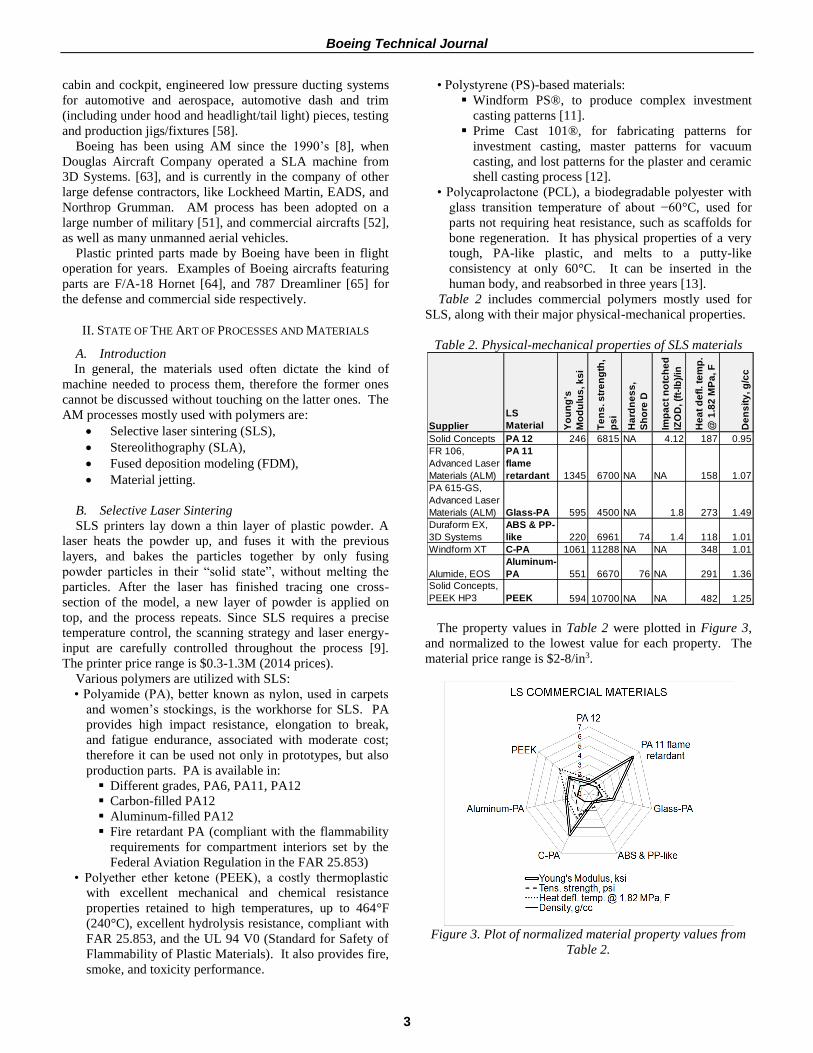
Table 2 includes commercial polymers mostly used for
SLS, along with their major physical-mechanical properties.
Table 2. Physical-mechanical properties of SLS materials
The property values in Table 2 were plotted in Figure 3,
and normalized to the lowest value for each property. The
material price range is $2-8/in3.
Figure 3. Plot of normalized material property values from
Table 2.
Supplier
LS
Material Yo
un
g's
Mo
du
lus
, k
si
Te
ns
. s
tre
ng
th,
ps
i
Ha
rdn
es
s,
Sh
ore
D
Imp
ac
t n
otc
he
d
IZO
D, (f
t-lb
)/in
He
at
de
fl. te
mp
.
@ 1
.82
MP
a, F
De
ns
ity
, g
/cc
Solid Concepts PA 12 246 6815 NA 4.12 187 0.95
FR 106,
Advanced Laser
Materials (ALM)
PA 11
flame
retardant 1345 6700 NA NA 158 1.07
PA 615-GS,
Advanced Laser
Materials (ALM) Glass-PA 595 4500 NA 1.8 273 1.49
Duraform EX,
3D Systems
ABS & PP-
like 220 6961 74 1.4 118 1.01
Windform XT C-PA 1061 11288 NA NA 348 1.01
Alumide, EOS
Aluminum-
PA 551 6670 76 NA 291 1.36
Solid Concepts,
PEEK HP3 PEEK 594 10700 NA NA 482 1.25

Boeing Technical Journal
4
Figure 4 displays some parts printed using SLS materials:
PA (left) and PEEK (right).
Figure 4. SLS parts made of PA (left), and PEEK (right)
C. Fused Deposition Modeling
The FDM process uses small diameter round feedstock fed
from reels. In the printer, the material is partly melted, and
extruded through a heated nozzle, resting on a supporting
platform if it constitutes the part’s first and bottom layer.
The nozzle moves to produce a one-layer thick cross section
of the part in x and y directions. The material hardens
immediately upon extrusion from the nozzle [9]. When the
layer is completed, the building board is lowered in z-
direction and the next layer is built on top. In this way a 3D
geometry is created one layer (slice) at the time. Nozzle and
platform move according to 3D-CAD data defining the part
geometry. Due to the thermal fusion, the material bonds with
the layer beneath and solidifies, forming a permanent
bonding of two layers. The printer price range is $11,000-
$500,000 (2014 prices).
Polymeric materials for FDM are:
• Acrylonitile butadiene styrene (ABS), a ubiquitous
thermoplastic (from car bumpers to footwear, from Lego
to luggage), with high impact resistance and toughness.
It is selected for AM because its glass transition
temperature is high enough to reduce unwanted
deformation at slightly elevated temperatures, but low
enough to be safely attainable with standard extrusion
setups.
• Polycarbonate (PC), a durable material, with high
impact-resistance, used with non-AM processes for
compact discs, DVDs, and “theft-proof” plastic
packaging
• PC-ABS
• Polyphenylsulfone (PPSF, or PPSU): a costly
thermoplastic with outstanding heat resistance, good
mechanical strength and resistance to petroleum and
solvents
• Polyetherimide (PEI), an expensive amorphous
thermoplastic with a great balance of thermal,
mechanical and chemical properties. PEI has higher
flexibility, and impact resistance than ABS.
Particularly, the PEI Ultem 9085 (a PEI-PC blend) is
preferred where high flame, smoke, and toxicity (FST)
rating, and high strength-to-weight ratio are required
• Polylactic acid (PLA), a bioplastic produced from corn
or dextrose. It is transparent, and in its characteristics
resemble conventional petrochemical-based mass
plastics, like polyethylene terephthalate (PET), PS or PE
(polyethylene). Offered in soft (rubbery and flexible)
and hard grades, it is increasingly very popular as an
alternative to ABS, due to higher maximum printing
speeds, and lower layer height than the former, leading
to smoother surface and higher geometrical resolution.
• Room temperature vulcanizing (RTV) silicone, a type of
silicone rubber made from a two-component system that
is base plus curative [53]
• PA, mentioned in section B
• PS, mentioned in section B.
Table 3. Physical-mechanical of FDM materials
The properties values in Table 3 were charted in Figure 5,
and normalized to the lowest value for each property. As for
SLS materials, also FDM polymers offer a good range of
property values, allowing some design freedom. The price
of FDM materials ranges from about $3 to $6 per cubic inch.
Figure 5. Plot of normalized material property values listed
from Table 3
D. Stereolithography
The SLA process requires a photosensitive liquid polymer,
filling a tank that also includes a platform movable in z-
direction. At the beginning, the platform is located closely
below the surface of the material. A UV-laser traces the
cross-section of the part, causing the first and top slice of the
resin to solidify in the respective area. Subsequently, the
Ma
teri
al
Yo
un
g's
Mo
du
lus
, ks
i
Te
ns
. str
en
gth
,
ps
i
Ha
rdn
es
s,
Sh
ore
D
Imp
ac
t n
otc
he
d
IZO
D, (
ft-l
b)/
in
He
at
de
fl. t
em
p.
@ 1
.82
MP
a, F
Sp
ec
ific
gra
vit
y
ABS 236 3200 R105 2 169 1.05
PPSF 300 8000 M86 1.1 372 1.28
PC 330 9800 R115 1 261 1.2
PEI-
PC 322 10400 NA 2 307 1.3
(*) redeyeondemand.com (Stratasys)

Boeing Technical Journal
5
platform is lowered into the resin basin by the thickness of
one layer (~5 μm). A sweeper blade applies a new film of
resin on top of the previously cured layer that is
subsequently cured by the UV-laser again. This process is
iterated and the following layer is fused to the solidified
layer. Support structures are required because of the low
stability of the part during the process. The part is tied to the
platform, in order to avoid any motion of the part while the
platform is lowered. The printer price range is $250-575k
(2014 prices).
Polymers employed in SLA are:
• Liquid photopolymers, that is UV-curable polymers such
as epoxy resins, and polyether(meth)acrylate-based
resins. They can feature mechanical properties similar
to engineering plastics such as ABS, PA, PC, PE,
polypropylene (PP), PP-ABS, high-density polyethylene
(HDPE), in order to make functional prototypes, and
end-use parts.
• Polyvinyl alcohol (PVA), a water-soluble synthetic
polymer, used as a dissolvable support material or for
special applications [54].
• PCL [55], mentioned in section B.
Table 4. Physical-mechanical properties of SLA materials
The properties values in Table 4 are represented in Figure
6, and were normalized to the lowest value for each property.
Except for hardness and density, the range of property values
provides users and designers with various options.
Figure 6. Plot of material property values from Table 4
In Figure 7 and Figure 8 the range of physical-
mechanical property values from Table 2, 3, and 4 identified
by printing process are plotted. SLS and FDM materials are
thermoplastics, whereas SLA materials are epoxy-based
thermosetting resins, and, therefore, feature a superior
Young’s modulus but inferior impact resistance and
deflection temperature than SLS and FDM. However, in
selecting the most suited AM material for a specific
application, designers typically focus on a combination of
cost and the material properties most relevant to the part
service performance.
Figure 7. Comparison of values of tensile modulus and
strength values of commercial additive manufacturing
polymers used in SLS, FDM, and SLA
We also point out that the tensile yield strength is
preferred to the tensile ultimate strength in designing
functional parts, but the former value was reported only for a
very few materials.
Supplier Ma
teri
al
Yo
un
g's
Mo
du
lus
, k
si
Te
ns
. s
tre
ng
th,
ps
i
Ha
rdn
es
s,
Sh
ore
D
Imp
ac
t n
otc
he
d
IZO
D, (f
t-lb
)/in
He
at
de
fl. te
mp
.
@ 1
.82
MP
a, F
De
ns
ity
, g
/cc
Somos 8110 UV Epoxy 46 2600 77 1.6 129 1.11
3D Systems Corp Accura 25
PP-
like 235 5510 80 0.4 127 1.19
Somos Waterclear Ultra 10122
ABS-
like 417 8000 86 0.46 121 1.13
3D Systems Corp Accura 60
PC-
like 420 9135 86 0.4 120 1.21
Huntsman RenShape SL 5530 HTR 532 7850 90 0.4 239 1.25
3D Systems Accura PEAK HYMS 653 9800 86 0.45 255 1.36
HTR = high temperature resistance
HYMS = High Young's mod., high tensile strength

Boeing Technical Journal
6
Figure 8. Comparison of values of impact strength notched
and heat deflection temperature values of commercial AM
polymers used in SLS, FDM, and SLA
Figure 9 compares the normalized price of the same part
quoted by the same AM house using SLS, FDM, and SLA
processes. The highest price for D80-ST is offset by the fact
that this material possesses superior mechanical properties
and is also stabilized to prevent premature thermal
degradation.
Figure 9. Normalized part prices across SLA, SLS, FDM for
the same part quoted by the same 3D printing house
Figure 10, instead, illustrates the difference in the actual
price of the same part to be 3D printed by the same vendor
using FDM. Ultem and PPSF are the most expensive of the
group, but they feature an unparallel combination of
mechanical properties, and heat and chemical resistance, that
makes them the only available option for specific demanding
application.
Figure 10. FDM prices of the same part for various
materials provided by the same vendor
In the case of AM polymers, materials with higher
property values do not necessarily result in more expensive
parts, even within the same process. In fact, we compared
the prices for the same part, whose mechanical properties
most relevant to its service performance were rigidity and
impact resistance. As Figure 11 to Figure 13 illustrate,
using materials with the highest combination of Young’s
modulus and impact strength, or highest Young’s modulus
alone, or highest impact strength alone led to the most
economical parts.
Figure 11. Part prices versus combination of elastic modulus
and impact strength values
Figure 12. Part prices versus elastic modulus values
Figure 13. Prices versus impact strength values
E. Jetting
One example of the jetting process is the version patented
by Objet, which is similar to inkjet document printing, but
0
500
1000
1500
2000
2500
0 0.25 0.5 0.75 1Pa
rt p
ric
e,
$
(Elastic mod.) * (Imp str.), Msi * ft-lb/in
FDM Quotes
Pa
rt p
ric
e, $
0
500
1000
1500
2000
2500
0.325 0.33 0.335 0.34 0.345 0.35 0.355
Pa
rt
pric
e,
$
Elastic modulus, Msi
FDM Quotes
Pa
rt p
ric
e, $

Boeing Technical Journal
7
instead of jetting drops of ink onto paper, the 3D printer jets
layers of liquid photopolymer onto a build tray and instantly
cures them with UV light. The fine layers build up to create
a precise 3D model or prototype that requires no post-curing,
and minimal post-processing. Along with the selected model
materials, the 3D printer also jets a gel-like support material
specially designed to uphold overhangs and complicated
geometries, and easily removed by hand or water [16].
Various polymeric materials are used for the jetting
process. They are compatible with the acrylic-based photo-
polymer technology, and two materials can be jetted at the
same time in specific concentrations and structures to
generate tens of compounds, featuring a wide range of
appearance (color, patterns, feel), and physical-mechanical
properties, in order to meet the performance requirements of
the end product. The hardness values range from Shore A
27 to A 95, to simulate various rubber products, but also
various rigid materials, ranging from standard plastics, like
PP, to the tough and temperature resistant materials, like
ABS, or engineering-plastics like polymethyl methacrylate
(PMMA). The heat deflection temperature can reach a
maximum of 203°F after thermal post treatment [17].
The other material involved with a version of the jetting
process called multi jet modeling [18] is wax, employed for
casting mid-sized and large foundry applications, casting of
fine-detail items, and dental prosthesis. Multi jet modeling,
or thermojet, is a fast rapid prototyping process, employed to
make models of wax-like plastics that are less accurate than
SLA objects. The printer features multiple spray nozzles,
spraying tiny droplets of melted liquid material which cool
and harden on impact to form the solid object [19].
F. Advanced Polymers
Currently, the following polymers are less commonly used
with AM equipment than those mentioned above, but they
will be improved and become more widespread in the next
future:
• Functionally graded materials (FGMs). They are
materials with spatially varying composition or
microstructure, ubiquitous in nature. One example is
the cross-section of a palm tree, featuring radial density
gradients resulting in bending stiffness varying across its
height. FGMs are obtained through the computer
control of the material distribution within a monolithic
structure, resulting in continuous gradients, and
structurally optimized designs with efficient use of
materials, reduction in waste, and production of highly
customizable features [20].
• Shape memory materials. They are made by mixing
polymer fibers into the composite materials used in AM,
resulting in the production of an object fixed in one
shape that can later be changed to take on new shape
[21]. The orientation and location of the fibers within
the composite determines the degree of shape memory
effects like folding, curling, stretching or twisting that
can be controlled by heating or cooling the composite
material. Another term for this type of material is
programmable matter [22]: materials that can morph
and self-assemble, or 4D printing, where the fourth
dimension is time, meaning that the printed objects
change shape or self-assemble in response to movement
or environmental factors, such as the presence of water,
air, and/or temperature changes.
• Bio-ink. It comprises stem cells and cells from a patient,
which can be laid down layer by layer to form a tissue.
Human organs such as blood vessels, bladders and
kidney portions have been replicated using this
technology. With the bio-ink, stem cells are immersed
in a biocompatible hydrogel ink, and the mix is then
printed into their target form.
• Bone-like material. It contains silicon, calcium
phosphate and zinc. In one experiment this material was
integrated with a section of undeveloped human bone
cells; in about a week, growth of new bone was seen
along the structure, this new material dissolved
eventually, and did not harm the patient.
• Hot glue. The greatest advantage of using the hot glue is
the extremely low cost of its gun. In one setup, the hot
glue gun can be connected to a XYZ computer
controlled plotter, or a CNC router type machine [23].
In another setup, an engineering student designed and
built a 3D printer using: a) LEGO NXT Intelligent
Brick; b) hot glue gun; c) fan; d) VHS camera motor,
powering the printer's extruder and build platform. NXT
is basically a 32-bit microprocessor and flash memory
equipped ports for attaching motors and sensors [24].
III. FUTURE MATERIALS
A. General Requirements
Predicting future polymers for AM is difficult, and can be
most successful only in the short term, because new
materials appear at extraordinarily fast pace, and companies
are understandingly secretive about the materials they have
in their pipeline. Tim Caffrey of Wohlers Associates, a
consulting firm specialized in AM, agrees: "With 3D
printing, we don't necessarily know where it's going."
Fortunately, some valuable indications to anticipate future
AM materials have come from some reports prepared by AM
experts from industry and academia [27, 28], that point out
what topics should be addressed by future material research
in order to meet additional requirements. Another source of
information was papers on the latest academic research
activities in AM polymers.
The handful of current AM polymers does not meet the
requirements of the majority of commercial products, hence
there is a demand for better materials to use as feedstock for
AM. Indeed, materials are considered “the real issue and the
biggest opportunity in AM” [29], therefore there are
opportunities for new or improved materials. The market
applications will direct the material research and
development, with the medical field playing a major role due
to its number of highly priced applications.
Broadly speaking, the effort to gain new applications will
drive widening the range of AM polymers, and improving
their physical-mechanical performance vs. the performance
of the same polymers when used in conventionally fabricated
counterparts.

Boeing Technical Journal
8
More competition among materials providers will cause
the price of standard AM polymers to drop, and the new
materials should be competitively priced, unless their
performance justifies a price premium. Reusable materials
are already available. In fact PA not melt during the SLS
process is already reused, and in fact the patent “Method and
system for reuse of materials in additive manufacturing
systems” was awarded to Stratasys in 2013. More
sustainable materials including recycled, reusable, and
biodegradable materials will emerge, further decreasing
materials costs [30]. FGMs will be further developed, and
represent a particularly high-value application for AM,
enabling also graded geometries through the part’s volume,
providing additional functionality [27].
David Leigh believes that custom formulations of existing
PA (such as PA11, and PA12) and PEKK will be available
for SLS in the short term, whereas in the longer term better
formulations of PEEK, PEKK, PA, and blends including
flame retardants and filled/fiber composites will be provided.
He also expects that most of the future focus on material
properties will be directed to medical grade and high
temperature performance, and work on electrical properties
will aim primarily at the development of hybrid printers that
could fuse material with a laser and print conductive material
with a print head [58].
According to Stephen Hanna, VP of Global Materials
Sales and Marketing of 3D Systems, a large manufacturer of
3D printers based on FDM and polyjet technologies, the
focus will continue to be on increasing the functionality of
the materials, to extend the range of manufacturing
application. “To achieve this,” he explains, “materials must
meet the following design demands.
• High stability. We are focused on developing materials
that are more stable over longer and longer durations,
pushing the useful life of printed parts further and
further. To do this, materials must be environmentally,
mechanically and dimensionally stable over time. We
have this in some materials, but not all. We believe that
improvements in these areas will greatly increase
adoption and applicability of 3D printing to
manufacturing applications.
• Improved mechanical properties. We believe that
improved properties will generate more applications.
This is not just better properties, but also a wider variety
of properties that can be addressed with 3D printing. 3D
Systems offers a wide range of materials now that range
from 1000 MPa to 10,000 MPa in flexural modulus! A
huge range! But ranges of ductility, impact resistance,
hardness are also important.
• Other properties. Special properties, be they electrical,
medically related, chemical resistance or other, could be
important for enabling new and emerging applications.
3D Systems careful evaluated new application areas for
3D printing and will focus material developments to
enable those where there is significant potential.” [59]
Many current SLA resins have softening temperatures
under 100°C, and hence they have limited usefulness in high
temperature applications. SLA polymeric formulations will
be investigated that will meet the growing demand for an
AM resin type curable at a broader UV bandwidth, resulting
in a wider range of softer to stiffer materials than the current
options. To broaden the use, new SLA resins with improved
performance, such as better mechanical properties and higher
use temperatures, must be developed.
Common epoxy-based materials used for SLA are not
suitable for medical applications due to the known irritating
and cytotoxic (that is resulting in cell damage or cell death)
effects on human cells, resulting mainly from uncured
epoxies in the cured polymer prototypes [34]. The studies
on non-toxic materials will continue, in order to overcome
these severe problems of the biological incompatibility, and
extend their applications.
Improvements in specific properties, like tensile strength,
and elastic modulus, will be achieved not only in single
materials for AM, but also in new combinations of materials,
such as the current iron-ABS and copper-ABS for FDM [31]
and PP-zirconia (ZrO2) [32], and Al2O3-PP [33] for SLS.
There is large and qualified consensus [28] that the most
likely AM polymers in the next future will comprise:
• Carbon-fiber-reinforced polymers (CFRPs), including
carbon nanofiber reinforced materials
• Liquid-crystal polymers (LCPs)
• Biodegradable materials, such as polycaprolactone.
Currently, a few options exist for carbon-fiber parts made
with AM. One challenge is material cost and production on a
scale that enables commodity-priced carbon fiber PA.
B. Carbon Fiber-Reinforced Polymers (CFRPs)
A class of CFRPs comprises polymers reinforced with
carbon nanomaterials, such as carbon nanotubes (CNTs),
which are rolled-up one-atom thick sheets (called grapheme)
of carbon. Adding nanomaterials is a way to reinforce and
stiffen a “matrix” material compatibly with the AM layer-by-
layer printing pattern that prevents laying a continuous
reinforcement in the z direction across the part layers. CNTs
constitute one area of development for AM polymers, and a
comprehensive up-to-date overview of CNT applications to
AM is provided in [35].
CNTs are already added to polymers to improve their
mechanical, thermal, and electrical properties [36, 37].
Similarly, when added to SLA polymers, such as UV-curable
epoxy resins, and SLS materials like PA12, they improve the
mechanical properties of the printed part. Specifically, in the
case of SLA, CNTs raise the tensile strength and fracture
stress, but also increase brittleness compared to the unfilled
resin [38, 39], therefore we expect in the next future material
research directed at reducing the brittleness of the printed
parts, without penalizing the tensile strength and fracture
stress.
As to SLS, conventionally fabricated parts in pure PA12
have higher tensile modulus and impact strength compared
to SLS parts in PA12/nanosized carbon black (CB) [40],
hence work will be likely carried out with PA12 and CB to
reduce or close the gap in mechanical performance between
SLS parts and extruded or molded parts, aiming at possibly
increasing the adhesion at the interface between PA and CB,
and consequently making the load transfer between the two
components more effective. Efforts will be also made to

Boeing Technical Journal
9
find the optimal printing conditions for CB powder blended
with PA12 powder, in order to improve mechanical
properties such as the flexural modulus, and reduce the
fraction of particles not melt during the process.
The surface quality of 3D printed parts depends on the
specific process resolution, and “size” of the raw material,
and for SLS the typical layer thickness is 60-200 um, and the
average roughness Ra can be as low as Ra = 8.5 um
(DuraForm PA by 3D Systems). Surface quality is
obviously important in applications where appearance is a
requirement, such as presentation models, but also in others
where the surface is functional, such as in the case of wind
tunnel testing models, where the surface roughness
significantly affects the drag coefficient [41]. Studies will be
conducted to improve the surface finish of PA12/CNFs vs.
PA12, focusing also on understanding the influences of
parameters affecting surface roughness, and dimensional
accuracy during fabrication.
Because varying the loadings of nanomaterials during the
print enables to fabricate parts with graded material
properties, graded materials will also be further studied.
On the other hand, the diffusion of nanomaterials in AM
applications has to overcome the following challenges [35],
if improved materials are to be formulated:
• Enhancing dispersion of CNTs in the matrix has been a
challenge for some time [42] and still is. Agglomeration
of the particles makes the nanomaterials behave as a
bulk, and lose their unique properties. To increase
dispersion, nanomaterials can be functionalized with
organic linker molecules keeping the particles away
from each other, even when embedded into the printing
media, ultimately improving the properties of the final
parts.
• Because the cure depth of SLA parts can be adversely
affected by the presence of nanomaterials due to their
ability to absorb the UV light, finding the ideal
wavelength that will solidify the polymer without being
influenced by the nanomaterial will enable a cure
throughout the part.
• Reducing the porosity of SLS parts, for example by
synthesizing core-shell nanostructures, with the core
made of nanomaterial, and the shell of the printing
material, such as PA12, or PA11 [43]. Lower porosity
translates into higher mechanical properties.
C. Liquid Crystal Polymers (LCPs)
One polymer family likely to be more common with AM
is LCPs. LCPs are a class of aromatic polyester polymers,
inert, and resistant to high temperature, that can be melted
and molded. They exist in a state that has properties between
those of conventional liquid and those of solid crystal. Upon
melting, the polymer chains undergo parallel ordering in the
direction of the flow, resulting in anisotropic physical,
mechanical, and optical properties, with superior mechanical
properties in the flow direction. LCPs are already used with
SLA, and new liquid-crystal resins will continue to be
developed [44, 45], with the goal to raise properties such as
the glass transition temperature (and hence the maximum
service temperature), and fracture toughness, and ultimately
gaining new uses like under-the-hood automotive
applications.
A class of LCPs for SLA that will be still studied in the
near future is the lyotropic liquid crystals (LLCs): a material
is called lyotropic if it forms liquid crystal phases upon the
addition of a solvent. LLCs have been recently studied to
be used to control polymer structure at the nanometer scale
and ultimately improve material properties [46].
D. Other Materials
One future material is bio-ink, which is already available,
but requires further development, to overcome its key,
opposing properties that make it complicated to handle. On
one hand, bio-ink must be fluid enough to flow through the
printing nozzle without damaging cells that are subjected to
shear forces as they come out of the printer head. On the
other hand, bio-ink must be stiff enough to hold its shape
after printing to prevent the material from oozing into a
shapeless mass.
Also on innovation watch list is AM of silicone
nanostructure [47], and compounded polymers, such as the
current ProPell™, a compound of thermoplastic PU, and
polyether block amide (PEBA), introduced recently by
Foster Corporation for improved medical catheters [48].
E. Future Polymer Properties
There is consensus that the future AM polymers will have
to feature improvements in the following properties, opening
a host of new applications, like commercial aircraft cockpit
indoors [28]:
• Fire resistance
• Thermal conductivity
• Electrical conductivity
• Self-healing properties
• Recyclability.
Table 5 contains the predicted dates when LCPs and
CFRPs will have frequent use in FDM and SLS [28].
Table 5. Predicted dates for frequent use of LCPs and
CFRPs in FDM and SLS
MATERIALS FDM SLS
CFRPs 2017 2017
LCPs 2020 2020
F. Future Area of Study
The design of printed parts is at its early stage, and in fact
design guides for printing parts have recently started by
companies using AM and seeking to maximize its benefits.
Therefore, investigating the failure mode of printed parts
could provide designers with insightful information
instrumental to take full advantage of material and part
performance. The cross section morphology of polymeric
printed parts is not exactly the same as that of parts produced
through conventional processes, and hence the fracture
surface analysis of printed parts may require some
customization. In fact Figure 14 illustrates the significant
porosity of a failed polycarbonate FDM part analyzed by
Boeing BR&T Philadelphia.

Boeing Technical Journal
10
Figure 14. Fracture surface of polycarbonate 3D part for
unmanned vehicle
IV. FUTURE PROCESSES
AM polymers are function not only of their chemical
formulation, but also their printing process, therefore the
future of AM polymers depends also on the future of printing
processes. First, a better understanding of the physics of AM
processes will be achieved to capture the complexity in the
multiple interacting physical phenomena, and better exploit
the capabilities of the materials. Understanding the material
properties of AM materials after they have been processed to
print the part is regarded by some as the most important
aspect of any future improvement.
The AM processes will have to meet the following
technology-specific requirements [28, 9]:
• Higher build-up rates, higher dimensional accuracy, and
better surface quality
• Lower maintenance costs
• Lower machine acquisition costs.
• Larger build-chamber volumes
• High process stability
• Quality control process after job completion, and, even
better, on-line quality control processes, that can be
crucial for a broad application of AM in the future.
• Continuous certification for aircraft, automotive, and
electronics manufacturing equipment
• Controlling the composition of the material of the printed
part at the nano level. For example, using multi-material
AM processes, we can print in the same part hard and
soft materials resulting in a component with peculiar
new structural behavior.
A current advanced development is complementing AM
with subtractive and molding processes [49].
One accomplishment that if completed would multiply
AM applications is available databases of the physical-
mechanical properties and allowables of the AM materials.
Unfortunately, comprehensive versions of such data bases
are costly and lengthy; therefore collaborations among
industry, academia, and government will be beneficial in
order to reach this goal faster.
V. ACKNOWLEDGMENT
Greatly acknowledged are: my Boeing colleagues Douglas
Anderson, Brett Lyons, Brian Martinek for their important
comments and information; industry executives and experts
Bill Cowan (EOS), Stephen Hanna (3D Systems), David
Leigh (Harvest Technologies), and Mark Menninger (3D
Systems) for their invaluable insights and predictions.
REFERENCES
[4] Wohlers Report 2015
[5] “Print me a Stradivarius”. Web. 10 Feb. 2011. 6 Jan.
2014. <http://www.economist.com>
[6] Searle N., “3D Printing Patents – New report”. 19
Nov. 2013. Web. 11 Jan. 2014.
<http://www.ipo.gov.uk/blogs/ipofacto/tag/additive-
manufacturing>
[8] http://www.tctmagazine.com/3D-printing-
news/boeing-files-patent-for-3d-printing-aircraft-parts/
[9] Gausemeier J., “Direct Manufacturing Research
Center (DMRC), Germany, Thinking ahead the Future of
Additive Manufacturing – Innovation Roadmapping of
Required Advancements”, University of Paderborn, Direct
Manufacturing Research Center (DMRC), Paderborn,
Germany, 2013. n.d. Web. 13 Jan. 2014
<http://http://dmrc.uni-paderborn.de >
[11] “Windform. Materials for additive manufacturing”.
n.d. Web. 13 Jan. 2014. <http://www.windform.it>
[12] “Materials and Material Management”, n.d. Web. 3
Jan. 2014. <http://www.eos.info/material-p>
[13] “Tech Updates” Design-2-Part Magazine. Vol. 30,
No. 8, Eastern Edition, October 2013: 26.
[16] “How PolyJet 3D Printing Works”, n.d. Web. 8 Dec.
2013. <http://www.stratasys.com/3d-
printers/technology/polyjet-technology>
[17] Langnau L., “A multitude of materials for additive
manufacturing”. 3 Oct. 2011. Web. 13 Dec. 2013.
<http://www.makepartsfast.com/2011/10/2254/2011-make-
parts-fast-handbook-materials>
[18] “How PolyJet 3D Printing Works”. N.d. Web. 8 Dec.
2013. <http://www.stratasys.com/3d-
printers/technology/polyjet-technology>
[19] “What is 3DP?” n.d. Web. 29 Nov. 2013.
<http://metals.about.com/library/weekly/aa-rp-mjm.htm>
[20] Oxman, Keating, Tsai, “Functionally Graded Rapid
Prototyping”, Mediated Matter Group, MIT Media Lab, n.d.
Web. 23 Dec. 2013
<http://materialecology.com/Publications_FGRP.pdf>
[21] “CU-Boulder researchers develop 4D printing
technology for composite materials”. 22 Oct. 2013. Web.
<http://www.colorado.edu/news/releases/2013/10/22>
[22] Reilly M., “What Is 4-D Printing?” 24 Nov. 2013.
Web. <http://www.slate.com/articles/
health_and_science/new_scientist/2013/11/_4_d_printing_
at_the_mit_self_assembly_lab_the_future_will_build_itself.
html>
[23] Favreau C. “Hot Glue Gun Extruder for Your CNC
Machine or 3D Printer”,
<http://www.instructables.com/id/Hot-Glue-Gun-Extruder-
for-Your-CNC-Machine-or-3D-P>. Accessed 4 Dec. 2013.
[24] Palermo E., “Build Your Own 3D Printer Out of
LEGOs”. 18 Jun. 2013. Web.

Boeing Technical Journal
11
<http://www.technewsdaily.com/18558-build-your-own-3d-
printer-out-of-legos.html>
[27] Bourell D.L., Leu M.C., Rosen D.W., Eds,
“Roadmap for Additive Manufacturing: Identifying the
Future of Freeform Processing”, Univ. of Texas, Austin, TX,
2009
[28] Shi S. et al., “2012 Emerging Global Trends in
Advanced Manufacturing, by the Institute for Defense
Analysis”, Institute for Defense Analyses, Alexandria, VA,
March 2012. <http://www.wilsoncenter.org>
[29] Tuck C., University of Nottingham, UK
[30] Jurrens K., “NIST Measurement Science for
Additive Manufacturing Engineering Laboratory”, 2013
[31] Nikzad M., Masood S.H., Sbarski I., “Thermo-
mechanical properties of a highly filled polymeric composite
for Fused Deposition Modeling”. Materials and Design, 32
(2011): 3448–3456
[32] Shahzad K, Deckers J, Zhang Z, Kruth JP,
Vleugelfor J, “Additive manufacturing of zirconia parts by
indirect selective laser sintering”. Journal of the European
Ceramic Society 34 (2014); 81-89
[33] Shahzad K, Deckers J, Kruth JP, Vleugelfor J,
“Additive manufacturing of alumina parts by indirect
selective laser sintering and post processing”, Journal of
Materials Processing Technology 213 (2013): 1484– 1494
[34] Bens, Seitz, Bermes, Emons, Pansky, Roitzheim,
Tobiasch, Tille, “Non-toxic flexible photopolymers for
medical SLA technology”. Rapid Prototyping Journal, Vol.
13, Issue 1, (2012): 38-45
[35] Ivanova O. S., Williams C. B., Thomas T. A.,
“Additive Manufacturing (AM) and nanotechnologies:
promises and challenges”. Web. 13 December 2013
<http://utwired.engr.utexas.edu>
[36] Coleman, J.N., U. Khan, and Y.K. Gun'ko,
“Mechanical Reinforcement of Polymers Using Carbon
Nanotubes”. Adv. Mater., 18(6) (2006): 689-706.
[37] Farzana H., Mehdi H., Masami O., Russell E. G.,
“Polymer-matrix Nanocomposites, Processing,
Manufacturing, and Alication: An Overview”. 2006.
<http://www.imechanica.org>
[38] Sandoval, J.H. and R.B. Wicker, “Functionalizing
Stereolithography Resins: Effects of Dispersed Multi-Walled
Carbon Nanotubes on Physical Properties”. Rapid
Prototyping J., 2006. 12(5): 292-303.
[39] Sandoval, J.H., et al., “Nanotailoring
Photocrosslinkable Epoxy Resins with Multi-Walled Carbon
Nanotubes for Stereolithography Layered Manufacturing”.
J. Mater. Sci., 42 (2007): 156-165.
[40] Bai, J; Goodridge, R. D; Hague, R. J.M.; Song, M.
“Improving the mechanical properties of laser-sintered
polyamide 12 through incorporation of carbon nanotubes”
Polymer Engineering and Science, 53(9), pp.1937-1946.
[41] Daneshmand, S, Aghanajafi, C., “Description and
Modeling of the Additive Manufacturing Technology for
Aerodynamic Coefficients Measurement”, Journal of
Mechanical Engineering 58 (2012) 2: 125-133
[42] Xiea X., Maia Y, Zhoub X, “Dispersion and
alignment of carbon nanotubes in polymer matrix: A
review”, Materials Science and Engineering Reports,
Volume 49, Issue 4, 19 May 2005: 89–112
[43] Zheng, H., et al., “Effect of Core-Shell Composite
Particles on the Sintering Behavior and Properties of Nano-
Al2O3/Polystyrene Composite Prepared by SLS”. Mater.
Lett. , 2006. 60: 1219-1223.
[44] Schultz J. W., Ullett J. S., Chartoff R. P., Pogue
R.T., “Novel Liquid Crystal Resins for Stereolithography:
Mechanical and Physical Properties”, 21 Nov. 2013
<http://www.utwired.engr.utexas.edu>
[45] Chartoff R.P., Schultz J.W., Bhatt J., Ullett S.,
“Properties of a High Temperature Liquid Crystal
Stereolithography Resin”. 1998.
<http://utwired.engr.utexas.edu>
[46] Forney B. S., “Controlled polymer nanostructure
and properties through photopolymerization in lyotropic
liquid crystal template”, Ph. D Thesis, 2013, University of
Iowa. N.d. Web. 23 Jan. 2013. <http://ir.uiowa.edu >
[47] “Tech Updates”. Design-2-Part Magazine. Vol. 30,
No. 8, Eastern Edition, October 2013, p. 18. The Job Shop
Company, Inc.
[48] “Advanced Materials”. Design-2-Part Magazine.
Vol. 30, No. 8, Eastern Edition, October 2013, p. 122. The
Job Shop Company, Inc.
[49] Gaines D. “Southern California company
complements additive manufacturing with subtractive and
molding processes” Design-2-Part Magazine. Vol. 30, No. 8,
Eastern Edition, October 2013, p. 104. The Job Shop
Company, Inc.
[51] Wooten, J. Aeronautical Case Studies Using Rapid
Manufacture. Chapter 15 in Rapid Manufacturing: An
Industrial Revolution for the Digital Age, edited by N.
Hopkinson, R. Hague, and P. Dickens. Chichester, U.K.:
John Wiley & Sons Ltd., 2006.
[52] Lyons, The Bridge, published by National Academy
of Engineering, Vol. 42, No. 1, Spring 2012
[53] “RTV Molding With PolyJet or FDM Patterns”.
n.d. Web. 10 Jan. 2013.
<http://www.stratasys.com/alications/manufacturing-
tooling/rtv-molding>
[54] Thomas G. P., “Materials Used In 3D Printing and
Additive Manufacturing”. Web. 4 Feb. 2013.
<http://www.azom.com>
[55] Mäkitie A. A., et al., “Novel additive manufactured
scaffolds for tissue engineered trachea research.” Acta
Otolaryngol. 133:412-417, 2013. Web.
[58] Paesano A., Article submitted to Design2Part
magazine, The Job Shop Company Inc.
[59] Paesano A., Article submitted to Design2Part
magazine, The Job Shop Company Inc.
[61] Boschetto A., Giordano V., Surface roughness
prediction in fused deposition modeling by neural networks,
International Journal of Advanced Manufacturing
Technology
[62] Ahn D., Kim H., Lee S., Surface roughness
prediction using measured data and interpolation in layered
manufacturing, Journal of Materials Processing Technology,
209 (2009) 664‐671

Boeing Technical Journal
12
[63] "Aerospace Production", Aircraft Engineering and
Aerospace Technology, (1994),Vol. 66 Iss 6 pp. 20-35.
http://dx.doi.org/10.1108/eb037529
[64] http://www.additivemanufacturing.media/articles/the-
aircraft-imperative
[65] https://3dprint.com/26081/3d-printing-aerospace-5-
uses/
BIOGRAPHY
Antonio Paesano has been with Boeing since 2010 as a
Manufacturing R&D engineer, supporting V-22, H-47, 787,
737, EMARSS, ecoDemonstrator, and LIFT! programs, and
BR&T Spain. He is active in composite materials, additive
manufacturing, measurements and analysis, Six Sigma, FOD
control, RTLS-RFID, material properties-performance
relationship, physical-mechanical testing and analysis, and
test method development. He is a certified Six Sigma Green
Belt, and a trained Back Belt.
Prior to Boeing, he worked for Dow and the University of
Delaware, always in R&D.
He holds a Ph.D. in mechanical engineering, and a
specialization degree in Polymer Science. He holds two
patents, authored and co-authored 50 technical papers, and
contributed to two chapter books, one on design, the other on
engineering materials.