Embed Size (px)
Citation preview

Polymer Electrolyte Fuel Cell Lifetime Limitations: The Role of Electrocatalyst DegradationDebbie Myers and Xiaoping Wang – Argonne National Laboratory
Graham Hards, Sarah Ball, and Jonathan Sharman –Johnson Matthey Fuel Cells
Mallika Gummalla – United Technologies Research Center
Yang Shao-Horn – Massachusetts Institute of Technology
Paulo Ferreira – University of Texas at Austin
Dane Morgan – University of Wisconsin – Madison
Jeremy Meyers – University of Texas at Austin
Fuel Cell Technologies Program New Project Kick-Off Meeting
Washington, D.C., September 30-October 1, 2009
This presentation does not contain any proprietary or confidential information

2
Objective and Technical Targets
Objectives– Understand the role of cathode electrocatalyst degradation in the long-
term loss of PEMFC performance,– Establish dominant catalyst and electrode degradation mechanisms,– Identify key properties of catalysts and catalyst supports that influence
and determine their degradation rates,– Quantify the effect of cell operating conditions, load profiles, and type of
electrocatalyst on the performance degradation, and– Determine operating conditions and catalyst types/structures that will
mitigate performance loss and allow PEMFC systems to achieve the DOE lifetime targets.
Technical Targets– Durability with cycling 5,000 hours (<80ºC) and 2,000 hours (>80ºC)– <40% loss of initial catalytic mass activity; <30 mV loss at 0.8 A/cm²

3
Pt catalyst degradation mechanisms
Proposed mechanisms inferred from ex situ, pre- and post-mortem TEM and XRD analyses:– Pt coalescence via migration
across support (2D)– Erosion of carbon support– Pt dissolution of smaller
particles and re-deposition onto larger particles (3D)
– Pt dissolution and precipitation in ionomer/membrane
(3) Growth via Modified Ostwald Ripening
Carbon support
Pt => Ptx+ + xe- Ptx+ + xe- => PtDissolution Re-deposition
Transport of Ptx+ complex
(2) Detachment from carbon support
Carbon supportDetachment
(1) Coalescence via Crystal Migration
Carbon support
(4) Dissolution and Precipitation in the Ion ConductorPt => Ptx+ + xe-
Ptx+
complex
Membrane/ionomer
H2Pt single crystals
H2 + Ptx+ => Pt + 2H+
(3) Growth via Modified Ostwald Ripening
Carbon support
Pt => Ptx+ + xe- Ptx+ + xe- => PtDissolution Re-deposition
Transport of Ptx+ complex
(2) Detachment from carbon support
Carbon supportDetachment
(1) Coalescence via Crystal Migration
Carbon support
(4) Dissolution and Precipitation in the Ion ConductorPt => Ptx+ + xe-
Ptx+
complex
Membrane/ionomer
H2Pt single crystals
H2 + Ptx+ => Pt + 2H+Figure adapted from: Y. Shao-Horn et al., Topics in Catalysis, 46 (2007) 285–305.

4
Particle migration and coalescence May dominate at low cell voltages where Pt dissolution and carbon corrosion
rates are slow Predominance of this mechanism is indirectly supported by ex situ analysis of
particle size distributions Defects on carbon support may trap the Pt particles and limit their mobility Further work is necessary to:
– determine realistic trapping models– determine support properties mitigating this degradation mechanism– quantitatively describe Pt particle motion in an electrolyte environment– assess the conditions under which particle migration and coalescence are active
1 nm 1 nm 1 nm
Source: M. Asoro, D. Kovar, L.F. Allard, Y. Shao-Horn, and P.J. Ferreira (MIT, ORNL, UT-Austin)

5
Detachment of catalyst particles from the carbon support
Generally believed to be linked with carbon corrosion Debate as to whether the presence of Pt accelerates carbon oxidation Electrochemically-active surface area (ECA) loss is slower on lower surface
area carbons, with graphitized carbon showing the slowest rate of ECA loss Further work is necessary to determine:
– if lower ECA loss rates are due to larger initial Pt particle on lower surface area carbons or lower rates of carbon corrosion
– the extent to which carbon-support interactions, temperature, and relative humidity contribute to carbon corrosion-related ECA loss
5 nm 5 nm5 nm
Source: M. Asoro, D. Kovar, L.F. Allard, Y. Shao-Horn, and P.J. Ferreira (MIT, ORNL, UT-Austin)
6
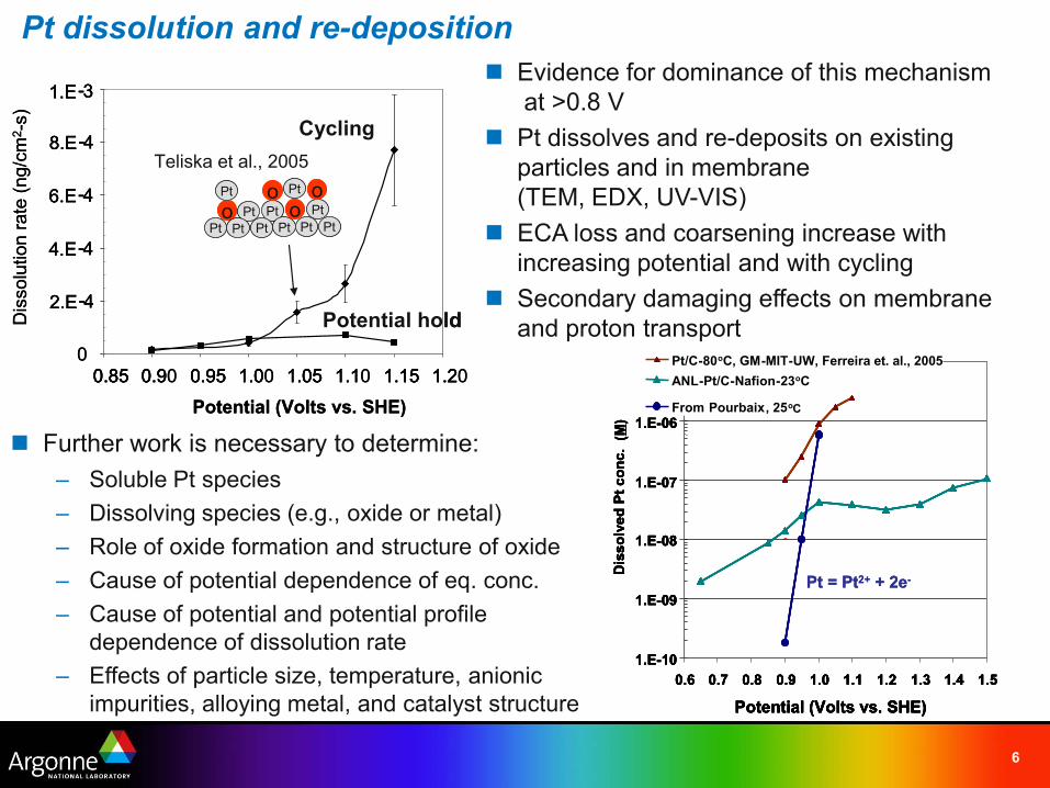
Further work is necessary to determine:– Soluble Pt species– Dissolving species (e.g., oxide or metal)– Role of oxide formation and structure of oxide– Cause of potential dependence of eq. conc.– Cause of potential and potential profile
dependence of dissolution rate– Effects of particle size, temperature, anionic
impurities, alloying metal, and catalyst structure
Evidence for dominance of this mechanismat >0.8 V
Pt dissolves and re-deposits on existing particles and in membrane(TEM, EDX, UV-VIS)
ECA loss and coarsening increase with increasing potential and with cycling
Secondary damaging effects on membrane and proton transport
Pt dissolution and re-deposition
1.E-3
Dis
solu
tion
rate
(ng/
cm2 -
s)
00.85 0.90 0.95 1.00 1.05 1.10 1.15 1.20
Potential (Volts vs. SHE)0.85 0.9 0.95 1.0 1.05 1.1 1.15 1.2
8.E-4
6.E-4
4.E-4
2.E-4
Cycling
oPt
Pt Pt
PtPt
Pt Pt Pt Pt Pto
Pt
o oTeliska et al., 2005
Potential hold
1.E-31.E-3
Dis
solu
tion
rate
(ng/
cm2 -
s)
00.85 0.90 0.95 1.00 1.05 1.10 1.15 1.20
Potential (Volts vs. SHE)0.85 0.9 0.95 1.0 1.05 1.1 1.15 1.2
8.E-48.E-4
6.E-46.E-4
4.E-44.E-4
2.E-42.E-4
Cycling
oPt
Pt Pt
PtPt
Pt Pt Pt Pt Pto
Pt
o ooPt
Pt Pt
PtPt
Pt Pt Pt Pt Pto
Pt
o oTeliska et al., 2005
Potential hold
1.E-10
1.E-09
1.E-08
1.E-07
1.E-06
1.E-05
0.6 0.7 0.8 0.9 1.0 1.1 1.2 1.3 1.4 1.5
Potential (Volts vs. SHE)
Dis
solv
ed P
t con
c. (
M)
Pt/C-80oC, GM-MIT-UWANL-Pt wireANL-Pt/C-Nafion-23oC
From Pourbaix, 25oC
1.E-10
1.E-09
1.E-08
1.E-07
1.E-06
1.E-05
0.6 0.7 0.8 0.9 1.0 1.1 1.2 1.3 1.4 1.5
Potential (Volts vs. SHE)
Dis
solv
ed P
t con
c. (
M)
Pt/C-80oC, GM-MIT-UW, Ferreira et. al., 2005ANL-Pt/C-Nafion-23oC
From Pourbaix, 25oC
Pt = Pt2+ + 2e-
1.E-10
1.E-09
1.E-08
1.E-07
1.E-06
1.E-05
0.6 0.7 0.8 0.9 1.0 1.1 1.2 1.3 1.4 1.5
Potential (Volts vs. SHE)
Dis
solv
ed P
t con
c. (
M)
Pt/C-80oC, GM-MIT-UWANL-Pt wireANL-Pt/C-Nafion-23oC
From Pourbaix, 25oC
1.E-10
1.E-09
1.E-08
1.E-07
1.E-06
1.E-05
0.6 0.7 0.8 0.9 1.0 1.1 1.2 1.3 1.4 1.5
Potential (Volts vs. SHE)
Dis
solv
ed P
t con
c. (
M)
Pt/C-80oC, GM-MIT-UW, Ferreira et. al., 2005ANL-Pt/C-Nafion-23oC
From Pourbaix, 25oC
Pt = Pt2+ + 2e-

7
Non-noble metal is leached from Pt alloy catalysts
Yang Shao-Horn et al., JES, accepted.
8
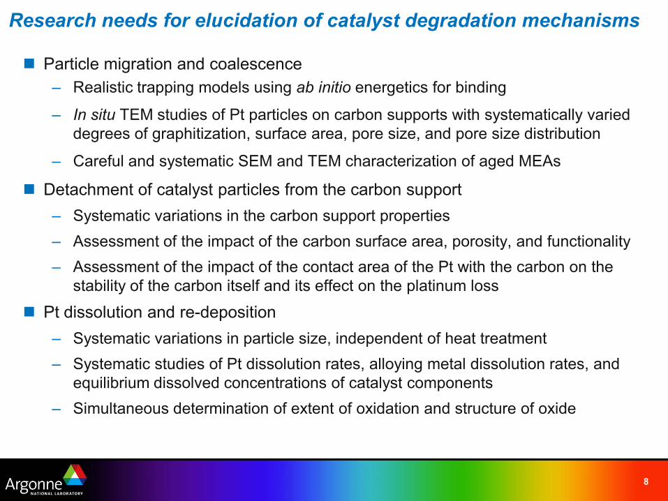
Research needs for elucidation of catalyst degradation mechanisms
Particle migration and coalescence– Realistic trapping models using ab initio energetics for binding
– In situ TEM studies of Pt particles on carbon supports with systematically varied degrees of graphitization, surface area, pore size, and pore size distribution
– Careful and systematic SEM and TEM characterization of aged MEAs
Detachment of catalyst particles from the carbon support– Systematic variations in the carbon support properties– Assessment of the impact of the carbon surface area, porosity, and functionality– Assessment of the impact of the contact area of the Pt with the carbon on the
stability of the carbon itself and its effect on the platinum loss
Pt dissolution and re-deposition– Systematic variations in particle size, independent of heat treatment– Systematic studies of Pt dissolution rates, alloying metal dissolution rates, and
equilibrium dissolved concentrations of catalyst components– Simultaneous determination of extent of oxidation and structure of oxide

9
Approach
Identify the degradation modes and factors contributing to degradation, using– Systematic cell degradation tests– In situ structural characterization of the catalyst– Fundamental out-of-cell studies– Theoretical modeling
Variables– Catalyst type and oxophilicity
• Pt, Pt alloys, acid-leached Pt alloys, core-shell– Catalyst particle size– Catalyst impurities– Type of carbon support
• varied surface area, pore size, and relative proportions of micro- and mesopores
– Cell operating parameters• Potential cycling profile, upper potential limit, cell temperature, RH on cathode
10
0102030405060708090
100
0 1 2 3 4 5 6 7 8Particle Size (nm)
Freq
uenc
y
1 hr2 hrs3 hrs5 hrs7 hrs10 hrs12 hrs14 hrs16 hrs
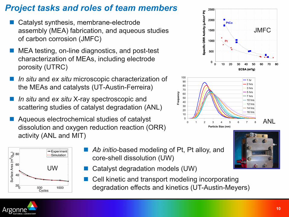
Project tasks and roles of team members Catalyst synthesis, membrane-electrode
assembly (MEA) fabrication, and aqueous studies of carbon corrosion (JMFC)
MEA testing, on-line diagnostics, and post-test characterization of MEAs, including electrode porosity (UTRC)
In situ and ex situ microscopic characterization of the MEAs and catalysts (UT-Austin-Ferreira)
In situ and ex situ X-ray spectroscopic and scattering studies of catalyst degradation (ANL)
Aqueous electrochemical studies of catalyst dissolution and oxygen reduction reaction (ORR) activity (ANL and MIT)
0
500
1000
1500
2000
2500
0 10 20 30 40 50 60 70 80
ECSA (m²/g)
Spec
ific
OR
R A
ctiv
ity (µ
A/c
m²P
t)
Pt
PtCo
0
500
1000
1500
2000
2500
0 10 20 30 40 50 60 70 80
ECSA (m²/g)
Spec
ific
OR
R A
ctiv
ity (µ
A/c
m²P
t)
Pt
PtCo
JMFC
UW
ANL
Ab initio-based modeling of Pt, Pt alloy, and core-shell dissolution (UW)
Catalyst degradation models (UW) Cell kinetic and transport modeling incorporating
degradation effects and kinetics (UT-Austin-Meyers)

11
Intended results of this project Relative lifetimes of platinum, platinum alloys, acid-leached alloys, and core-shell
catalysts in the MEA, independent of particle size and support effects Effect of MEA operating conditions, such as voltage cycling protocols, cell
temperature, and cathode relative humidity on MEA performance degradation Relationship between catalyst particle size and degradation rates and
mechanisms Effects of catalyst precursor impurities on the catalyst degradation rate Role of carbon support properties and carbon support degradation in cathode
performance loss Cathode catalyst atomic structure and oxidation state in the MEA environment
and how these are affected by cell conditions Roles of the extent of oxide formation, catalyst oxophilicity, and oxide structure in
catalyst degradation and relationship to ORR activity Mechanisms and rates of catalyst dissolution as a function of potential and
temperature and effect of extent of dissolution (i.e., sub-monolayer to multi-monolayer) on this mechanism
Loss of non-noble alloying or core metals as a function of catalyst structure (e.g., core-shell, acid-leached, ordered vs disordered)
Impact of catalyst component dissolution on cathode performance

12
Project timelineProject Schedule
Q1 Q2 Q3 Q4 Q1 Q2 Q3 Q4 Q1 Q2 Q3 Q4Task 1. Catalyst and Membrane-Electrode Assembly Fabrication
1.1 Benchmark Pt and one Pt alloy with varying particle sizes 1.2 Pt alloys, acid-leached alloy, core-shell on standard support1.3 Pt alloy catalysts with varying degrees of oxophilicity
1.4 Pt on supports with varying surface area, pore size, and pore size distribution
1.5 Catalysts with post-doping of catalyst precursor impurities
Task 2. Cell degradation studies/single cell cycling/parametric aging studies2.1 Accelerated stress testing of baseline MEAs and impact of operating conditions2.2 Advanced catalyst degradation mode identification 2.3 Effect of carbon support on MEA electrode performance loss2.4 Effect of catalyst impurities on MEA electrode performance loss
Task 3. Mechanisms of catalyst degradation and underlying physicochemical catalyst properties responsible for degradation
3.1 Roles of catalyst oxophilicity, extent of oxide formation, and structure of oxide in catalyst degradation 3.2 Influence of potential, temperature, and physical properties of catalyst on the rates and mechanisms of catalyst component dissolution3.3 Role of catalyst-support interactions and support degradation 3.4 Effect of particle size and catalyst type on ORR activity
Task 4. Ex situ microscopic and X-ray scattering characterization of catalysts and MEAs4.1 Optical microscopy, aberration-corrected STEM and high-resolution TEM w/ EDAX, EELS, XPS4.2 Small angle X-ray scattering
Task 5. Modeling5.1 Ab initio based modeling of Pt, Pt alloy, and core-shell dissolution
5.2 Catalyst degradation models including nature and role of oxide formation in catalyst degradation 5.3 Cell kinetic, transport model incorporating degradation effects/kinetics
Year 1 Year 2 Year 3
1 Milestone 1 (Y1-Q4): Development of initial macroscopic-based CV model plus ORR catalyst layer performance model, identification of parameters still needed. In situ and ex situ characterization of three classes of catalysts2 Milestone 2 (Y2-Q4): Development of macroscopic model of platinum dissolution and place exchange and completion of CV and ORR catalyst performance models. Determination of effect of carbon support properties and on cathode degradation rates and mechanisms.3 Milestone 3 (Y3-Q4): Integration of catalyst layer morphological evolution with ORR catalyst layer performance model. Performance degradation and comparison of pristine, as-received MEA to degraded as function of potential, oxide coverage, operating conditions Go/No-Go Decision Point (Y2-Q4): Demonstrated link between aqueous electrolyte studies of degradation mechanisms of three classes of catalysts and degradation observed in MEA tests.
1 2 3

13
Project deliverables
Integrated model of the loss of PEMFC performance relating to catalyst degradation that can be used as a predictive tool for estimating the lifetime of PEMFCs under a variety of operating conditions
Identification of performance degradation mechanisms for different catalyst types and operating conditions
Definition of catalyst and support physicochemical properties that influence or determine catalyst degradation
Definition of the operating conditions and catalyst properties that will allow automotive PEMFC power systems to achieve or exceed the DOE lifetime targets, while also meeting activity targets

14
Project budget and acknowledgements
Funding in $KFiscal Year
DOE Cost-Share
Total
2010 1,238 177 1,4152011 1,251 182 1,4332012 1,265 185 1,450Total ’10-’12
3,754 544 4,298
Financial support from DOE-EERE, Fuel Cell Technology Program
Nancy Garland, DOE Project Manager