Embed Size (px)
Citation preview

Product CatalogueDC/DC Converters and Power Supplies

About PolyampPolyamp Power division specializes in design and production of mainly DC/DC converters and some compatible Power supplies. Our DC/DC converters are used in applications demanding high reliability in rough environments. Thru the years countless applications in sectors like Railway, Energy, Process control, Vehicles, Military, Radio and Telecom etc.
We provide our DC/DC converters to customers worldwide, with an established sales distributor network or directly where we do not have a distributor. Polyamp have three locations; the head office in Sollentuna suburb to Stockholm, Sweden. We have design and manufacturing of DC/DC converters in Åtvidaberg 230 km south of Stockholm and La Chaux-de-Fonds in Switzerland.
Our DC/DC converters have practical MTBF > 1 Million hours and our official warranty is two years. However in case we discover a fault due to workmanship the warranty is much longer than that. We have no dedicated service department as we have worked with quality assurance methods since end of 1980-ties. Our delivery accuracy is around 98% on time, in a day to day basis and delivers to just-in-time schemes. Our quality system is approved for Nuclear Plants Class 1E.
The Systems Division of Polyamp specializes in the design, manufacture and supply of Underwater Electromagnetic Signature Management and Control Systems for Worldwide application within the International Naval Industry / International Navy authorities.
The types of system supplied are Advanced Degaussing systems for surface and submarine naval vessels. Electromagnetic Mine Sweep supply, Underwater Electric Potential (UEP/ELFE) sensors and electromagnetic design and measurement systems.
The SWECADE software can predict and design coil systems, dimension Degaussing systems, control fixed and movable ranges, support signature analyze and document the fleet vessels signature history. Please read from page 30.

TABLE OF CONTENT
About Polyamp ................................................................................... 2
Why Polyamp ...................................................................................... 4
Proven high reliability in rough environments ..................................... 5
General data ....................................................................................... 6
Why a CE mark? .................................................................................. 7
Polyamp standard DC/DC products................................................8 - 9
PSE100-series 100 W AC/DC ............................................................. 10
PSC-series 100-240 W AC/DC ........................................................... 11
PM50-series 50 W DC/DC ................................................................ 12
PM80-series 80 W DC/DC ................................................................ 13
PM150-series 150 W DC/DC .......................................................... 14
PM240-series 240 W DC/DC .......................................................... 15
PSE100-series 100 W DC/DC ......................................................... 16
PSE250-series 250 W DC/DC ......................................................... 17
PSC-series 150 W DC/DC ............................................................... 18
PSC240-series 240 W DC/DC ......................................................... 19
PM250-series 250 W DC/DC ..........................................................20
PM500-series 500 W DC/DC.......................................................... 21
PU300-series 300 W DC/DC ..........................................................22
PU500-series 500 W DC/DC ..........................................................23
PSC600-series 800 W DC/DC ......................................................... 24
PU1000-series 1000 W DC/DC .......................................................25
PC1000-series 1000 W DC/DC .......................................................26
PC2000-series 2000 W DC/DC ...................................................... 27
Special models .................................................................................. 28
DC Power System Configurations ...................................................... 29
Magnetic and Electric Signature Control ....................................30 - 33
About Polyamp ................................................................................. 34

For full specifications, manuals and other information, please visit www.polyamp.com
4
PM500-series
Installed within 5 minutesMounting brackets are provided with the delivery. Wall, chassis, DIN-rail and 19" rack mounting methods are available depending on the model selected. Plug-in units for Euro format, 3HE & 6HE are also available.
Quality system100% reliable products assured. We have a proven record of 98% on time delivery on a day base. We are what some customer call a 100% supplier, 100% quality and 100% on time.
MTBF & Life expectancyOur design is carefully made by our experienced de-sign team. This leads to very high practical MTBF and long life expectancy of our converters. Some units have predicted MTBF > 3 Million hours and most products will live 15-25 years.
Integrated mechanics and electronicsWe start a design with the mechanical considerations before integrating the electronics. This ensure very good cooling of all components. Low working temperature result in long life.
Products are CE markedas an apparatus in respect of Safety, EMC and also RoHS.
Input well filteredWe use well dimensioned EMC filters meeting low emis-sion and high immunity requirements.
Output well filteredWe have well designed EMC filters on the output, meet-ing low emissions and high immunity requirements. The output can therefore be used for voltage distribution without any additional EMC filters. Most competitors have no EMC filters on the output at all.
We specify working temp. without derating -25˚ to +55˚C is standard for our modules and -25˚ to +70˚C for our Euro cassettes.
Run a Polyamp at full load continuouslyWe have about 10% margin on the rated output power. Not always the case with competitors.
"Gold" colour not blackThe gold colour of our cases is chosen not only for its look. The thermal radiation at operating temperature is the same as black, but it absorbs much less heat from other equipments. Low working temperature = Long life expectancy.
Aluminum coverGives good cooling and also easy to recycle. We have an environmental program that minimize unfriendly mate-rials and workmanship. With small modifications it also permits to meet the EN 45545 Fire and Smoke standard.
Convection cooledOur designs are made for convection cooling. Self stand-ing units with no need for forced ventilation. Can be mounted in any direction.
No ventilation holesMinimize the risk of dust entering into the unit, which is important in industrial and mobile applications. Can be mounted in any direction.
Transport packingWe ship all units in single boxes or in cleaver card box frames. Safely protecting the product during transporta-tion. As there is only one material in the box it´s easy to recycle. Meets Grüne punkt .
Why Polyamp

For full specifications, manuals and other information, please visit www.polyamp.com
5
On-board trains
Industry, Process control Power plants, including Nuclear Vehicles: Electric & Military Telecom & Radiocom Naval, Off-shore platforms
DC/DC converters functions Voltage transformer Substitute to batteries
Galvanic separation EMC Filter
Polarity changer Combination of above
Stabilizer
Proven high reliability in rough environments

For full specifications, manuals and other information, please visit www.polyamp.com
6
DC/DC converters from Polyamp are a free stand-ing unit which will be installed within 5 minutes. The aluminum cover gives good cooling and also easy to recycle. We have an environmental pro-gram that minimize unfriendly materials and work-manship. Most of Polyamps converters are design for convection cooling. The in- and output have well designed EMC-filters, meeting low emissions and high immunity requirements.
Input protection In general we don´t supply our DC/DC converters with fuses because the fuse specifications vary between applications on dc voltages and another reason is that on DC distribution networks the fuse to the DC/DC con- verters should be at the distribution point, to protect the cables from short circuits. All models have a parallel or series diode to protect against input reverse voltages.
Inrush current On the input side there is an inrush current to charge the input capacitor. The level of inrush current depends on the systems impedance and voltage. Some models has inrush current limit circuits with NTC resistor and it can be optional on some. The PSC600-, PU1000- and PC2000-series have an active inrush current limit. Basi-cally we are reluctant to use NTC as inrush-current limit. In many DC/DC converter applications they are con-nected in redundancy or in by-pass to an AC/DC power supply. In such cases, the converter will not be able to supply enough current until the NTC warms up. All con-verters from Polyamp have a softstart which will charge the output capacitors in a controlled way during start up.
Parallel connection for more power By connecting two or more units in parallel you can achieve higher power systems. As Polyamp can supply converters up to 2000 W it´s usually suitable for very large systems.
Parallel connection for redundancy Each converter is specified to carry the whole load. The converters must have series diode and output alarms to provide fault indication in case of failure. The PU1000- and PC2000-series have an active current sharing control. The PSE and PSC has a passive balancing resistor that provide current sharing with option CR.
MTBF The statistical figure MTBF can be put at more than 1 Million hours at 40°C ambient temperature. This is based upon our historical data. However, the MTBF should not be confused with life expectancy. We design our converters for long life expectancy. As a result we get good practical MTBF values. Calculated MTBF values might be lower.
How to load / How to cool Our converters are specified and tested to work at a full ambient temperature range of -25 to +55°C or +70°C at 100% load. Continuous operation at high ambient temperatures reduces the life expectancy of a unit. It´s very efficient to arrange a small airflow around the converters. A 10°C lower ambient temperature will basi-cally doubles the life expectancy of the unit. A general feature of a Polyamp converter is that it´s relatively cool at full load. Consult Polyamp on general thermal man-agement questions for your application.
Ambient temperature and output power Our standard operating temperature range is -25 to +55°C with 100% load. It means that the temperature around the case has that temperature. Our DC/DC con-verters has relatively large coolers which provides some thermal after lag. Therefore temporary temperature peaks outside the range can be accepted. E.g. the rail-way standards EN50155 demands 15°C increase during 10 minutes.
Operating temperature up to +70°C can be achieved with derating and with forced air cooling up to 85°C. See below figure. The PSC and PSE series are specified up to +70°C without derating.
Please note that the life expectancy of a power supply unit is very linked to the ambient temperature. A rule of thumb is that 8-10°C temperature increase halves the life expectancy. In reality this is valid from about 30-40°C ambient temperature. -40°C is optional as we need to test that the unit starts at this temperature.
General data

For full specifications, manuals and other information, please visit www.polyamp.com
7
Product responsability is always with the manu-facturer. To help achieving a safe product a num-ber of EU directives have been issued. Using these directives and related harmonized standards the manufacturer must create a technical construction file (TCF), which will point to a number of require-ments that have to be met to achieve product safety.
A CE-mark indicates that the requirements have been investigated and the product found to be safe for the intended use. Together with the product documentation we provide a CE- decla-ration that not only specify to which Directives this product comply to but for the EMC directive also indicates the performance on both input and output.
EMC The reason is that there are several Directives that involve EMC and the EMC directive itself generated many Product standards for different sectors. How-ever the same Basic standards are used to measure the EMC performance, except for military applications. Our performance covers most of them e.g. Telecom, Power industry, Railways, Process industry etc. Below is listed some Directives that have EMC requirements:• EMC directive 2004/108/EC, • RTTED directive 1999/5/EC (Radio and telecom) • HSR directive 96/48/EC and CONRAIL directive 2001/16/EC. (Railways) • Marine equipment 2002/84/EC
Safety The Low voltage directive, 2006/95/EC has priority over the 2006/42/EC Machinery safety, for electric and elec-tronic products. The voltage limit of 50 Va.c. or 75 Vd.c, which in fact means that DC/DC converters us-ing voltages below that shall not refer to safety in the CE mark. However the revised directive accepts a CE mark on lower voltages if the product is made according to a harmonized safety standard, e.g. EN 60950.
Environmental The RoHS 2011/65/EC directive is now also included in the New approach principles and require a CE mark. All our components and materials are RoHS compliant, how-ever we still have 2 soldering lines, one with Lead free and one with Lead as parts of the industry do not want lead free soldering at the moment. The open scope of the RoHS directive stipulates to phase out lead 2019, however some application are excluded.
The conclusion is that a Polyamp CE mark means EMC and LVD directive (also below 75 Vd.c.) and the RoHS directive.
Other Directives The REACH 2006/21/EC directive has many aspects around substances. For most electronic manufacturers it is today and in future the list of reportable chemicals, that get successively longer, which causes problems. Polyamp has done a material analyze to screen critical areas.
The difference between the RoHS directive and REACH is that RoHS specify from homogeneous materials thus all single components, while the REACH consensus at the moment is the LRU level (Least Replaceable Unit) even the authorities has “substance is always a substance” attitude. As our units have a sturdy integrated mechan-ics, typically 80% of the weights of a unit consist of met-als, mostly Aluminum, Copper and Iron (Ferrites).
The current WEEE 2002/96/EC directive does not affect us as our products are included in other equipment. However the future WEEE (2012) directive might change that.
The EuP directive was amended to Directive (2009/125/EC). The most important amendment concerns the Directive’s scope, which has been extended from “energy-using” to so-called “energy-related” products. However this directive regards Eco design in general. Initial life cycle analyses (LCA) resulted in a focus on “in use efficiency” as it was the main environmental factor. Currently there are forces that what to challenge the used LCA model and reintroduce the original idea “from the mine, manufacturing, in-use to recycling” analyze.
Why a CE mark?

For full specifications, manuals and other information, please visit www.polyamp.com
8
Our DC/DC converter program covers a wide range of dc inputs from 10 V up to 750 Vd.c. This page helps you select the rigth DC/DC converter family depending of what demands you have. Polyamp guarantee full performance within the specified input range, which means 105% load capacity, 110% output voltage level at max rated operational temperature. Our voltages ranges are selected to meet international market demands.
12 V input Is used mainly in car related applications or small mo-bile systems or in back-up systems. 12 V input voltage is handled by the A input voltage range 10-30 V or an input range coded 12 (11-16V).
Input range Family code A = 10 - 30 Vd.c. PM50, PSE100, PSC150, PM150, PU300 12 = 11 - 16Vd.c.(*) PM250, PU300 12/27
A common question is if we can handle cranking down to 6 V. In general the converter switch off at <9.5 V. The PM50A input handles 6 V with derating, consult the datasheet for more information.
Applications around 12 V car systems are drowned by "cheap and dirty" converters as it is directed to consumers that usually do not use sensitive applications. A ciga-rette outlet supplied converter from good brand laptop manufacturer can kill a whole Police or Ambulance EMC environment. Polyamp deliver to Police and Ambulances, modified vehicles used around Swedish UN troops world-wide.
24 - 28 V input Is used in many applications. Use the B input code 20-60 V or the 24 input code 20-32 V.
Input range Family code B = 20 - 60 Vd.c. PM50, PSC150, PM150, PU300, PU600 B = 20 - 72 Vd.c. PSE100 24 = 18 - 32 Vd.c. PM80, PM240, PSC240, PU500, PU1000 24 = 20 - 32 Vd.c. (*) PSE200, PSE250, PM250, PC1000
24T = 14.4 - 33.6 Vd.c. For train EN 50155/IEC 60571 and forklifts, on demand
24T = 12 - 40 Vd.c. For some train markets, on demand
28T = 16 - 40 Vd.c. MIL-STD 1275-D (28V) / ISO 7637-2 (24V), on demand
An alternative in case you have cranking voltages use A input, see 12 V input. An A input version has always slightly lower efficiency than above mentioned inputs.
36 V input Is today mostly used in train applications and on the North American markets. Use the B input (20-60 V) or ask for a specific 36 input range. The 36 input code it is not in our standard input range but can be made on demand. For train or mobile applications a standard B-input range covers EN50155, IEC60571 train standards.
Input range Family codes B = 20 - 60 Vd.c. PM50, PSC150, PM150, PU300, PU600 B = 20 - 72 Vd.c. PSE100 36 = 28 - 50 Vd.c. PM80, PM240, PSC240, PU500, PU1000 36 = 30 - 50 Vd.c. (*) PSE200, PSE250, PM250, PC1000, PC1400 36T = 21.6 - 50.4 Vd.c. For train EN 50155/IEC 60571 and forklifts, on demand 36T = 18 - 60 Vd.c. For some train markets, on demand
48 V input Is used mainly in telecom related applications, where low emis sion is required. We have EN50022 level B on all such inputs. Use the B input code or 48. For EN50155, IEC60571 train standards use input code 48T with this the output power can be derated.
Input range Family codes B = 20 - 60 Vd.c. PM50, PSC150, PM150, PU300, PU600 B = 20 - 72 Vd.c. PSE100 48 = 38 - 60 Vd.c. PM80, PM240, PSC240, PU500, PU1000 48 = 41 - 60 Vd.c. (*) PSE200, PSE250, PM250, PM500 PC1000, PC1400, PC2000 48T = 28.8 – 68 Vd.c. For train EN 50155/IEC 60571 and forklifts, on demand 48T = 24 - 40 Vd.c. For some train markets, on demand
Polyamp standard DC/DC products

For full specifications, manuals and other information, please visit www.polyamp.com
9
60 - 96 V input 60 Vd.c. is used mainly in telecom applications on certain mar kets. We can make special inputs for 48-60 V input with 38-72 V input. 72 Vd.c. is used mainly in trains. Use our C input range or 72T. 96 Vd.c. is not very common these days, it has mainly been used in large fork-lifts. Use our C input range and require a series diode on the input.
Input range Family codes B = 20 - 72 Vd.c PSE100 C = 50 - 150 Vd.c. PM50, PSE100, PSC150, PM150, PU300, PU600 72 = 60 - 100 Vd.c. On demand 72T = 43.2 - 100.8 Vd.c For train EN50155/IEC 60571 and forklifts, on demand
110 V input Is used mainly on trains, in power plants and sub-sta-tion applications. High immunity levels are required. Use the D input (90-270 V) or 110 (93-150 V). For EN50155, IEC60571 train standards use our C-input (50-150 V) or 110T (66 – 154 V).
Input range Family codes C = 50 - 150 Vd.c. PM50, PSE100, PSC150, PM150, PU300, PU600 D = 90 - 270 Vd.c. PM50, PSE100, PSC150, PM150, PU300, PU600 110 = 88 - 150 Vd.c. PM80, PM240, PSC240, PU500, PU1000 110 = 93 - 150 Vd.c. (*) PSE200, PSE250, PM250, PM500 PC1000, PC1400, PC2000 110T = 66 – 154 Vd.c. For train EN 50155/IEC60571 and forklifts, on demand
220 - 250 V input Is used mainly in power plants and sub-station applica-tions. High immunity levels are required. Use the D input code or 220. The 250 V battery is not very common but can only be used with 220 inputs. Hy brid cars and sub-marines uses similar voltages, please contact us.
Input range Family codes D = 90 - 270 Vd.c. PM50, PSE100, PSC150, PM150, PU300, PU600 220 = 175 - 300 Vd.c. PM80, PM240, PSC240, PU500, PU1000 220 = 187 - 300 Vd.c. (*) PSE200, PSE250, PM250, PM500 PC1000, PC1400, PC2000
>300 V input Are used mainly in power plants, oil platforms, hybrid / electric car applications or in ROV and submarines. There are also applications for 600/750 Vd.c. in Traction & Metro applications according to IEC 60850. All those are special executions. The standard models we have are:
Input range Family codes E = 260 - 500 Vd.c. PSC150 440 = 350 - 500 Vd.c. PSC240 440 = 300 - 600 Vd.c. PU1000 600 = 400 - 900 Vd.c. PSD200 600/200
(*) Rated input voltage with max rating and temperature. The input accept < -35% of nominal input before switching of the converter. The output can drop to 95% of nominal output.

For full specifications, manuals and other information, please visit www.polyamp.com
10
OUTPUT AC INPUT
Voltage Current Power 85 - 264 Va.c. 85 - 135 Va.c. 176 - 264 Va.c.
5 V 12.0 A1 60 W PSE60ACW5
5 V 20.0 A1 100 W PSE100ACR5 PSE100AC5
13.2 V 4.50 A 60 W PSE60ACW13.2
13.2 V 7.60 A 100 W PSE100ACR13.2 PSE100AC13.2
15 V 4.00 A 60 W PSE60ACW15
15 V 6.70 A 100 W PSE100ACR15 PSE100AC15
24 V 2.50 A 60 W PSE60ACW24
24 V 4.20 A 100 W PSE100ACR24 PSE100AC24
48 V 1.30 A 60 W PSE60ACW48
48 V 2.10 A 100 W PSE100ACR48 PSE100AC48
EMC & SAFETYEN60950 class IEN61000-6-2, Immunity EN61000-6-3, Emission EN/IEC61000-4-4, 4 kV EN/IEC61000-4-5 level 2 & 3EN50121-3-2 & EN50121-4IEC62236-3-2 & IEC62236-4
OPTIONSSeries diode on output Train inputs Alarm relay with selectable NO/NC function
FEATURES85 to 264 Va.c. input 5 to 48 V output Logic alarm Operating temp. -25 to +70˚C, without derating Tropical coating Euroformat 8TE, 3HE DIN-rail, wall mounting or 19” sub rack
PSE100-series 100 W AC/DC
1) -25 to +55˚C 100% load, 70˚C at 75% load. With extra cooler, see picture at next page, the rating is 100% load at 70˚C.
DIN-rail mounted Model with N + TS35 clips
DIN or wall mounting Model with N (standard)
8TE for 19" sub rack mounting Model with L-panel (opt.)
The tables indicates the standard models.
Other input and output combinations on demand.

For full specifications, manuals and other information, please visit www.polyamp.com
11
10TE 12TE
POWER RANGES
Modell Watt Dimension
PSC100 100 W 10TE
PSC150 150 W 12TE
PSC240 240 W 12TE
AC INPUTS
Input code Input range Nominal input Frequency
ACR 85 - 135 V 100, 110 Va.c. 48 - 420 Hz
AC 176 - 264 V 220, 230, 240 Va.c. 48 - 420 Hz
ACW 85 - 264 V 110, 127, 230 Va.c. 48 - 420 Hz
SINGLE OUTPUT DUAL OUTPUTS TRIPLE OUTPUTS
Output Power Master output Slave output Power Master output Slave output Power
5 V 30.0 A 150 W 5 V 17.0 - 25.0 A 12 V 1.20 A 100 - 150 W 5 V 14 - 23.0 A ±12 V 1.20 A 100 - 150 W
12 V 12.5 A 150 W 5 V 17.0 - 25.0 A 15 V 1.20 A 100 - 150 W 5 V 14 - 23.0 A ±15 V 1.20 A 100 - 150 W
13.6 V 11.0 A 150 W 12 V 7.30 - 11.0 A 5 V 1 2.50 A 100 - 150 W
15 V 16.0 A 240 W 12 V 7.00 - 11.0 A 12 V 1.20 A 100 - 150 W
24 V 10.0 A 240 W 15 V 5.50 - 9.00 A 12 V 1.20 A 100 - 150 W
48 V 5.00 A 240 W 24 V 3.00 - 5.00 A 24 V 1.20 A 100 - 150 W
110 V 2.20 A 240 W
FEATURES85 to 264 Va.c. input 5 to 110 V outputUp to three outputs Operating temp. -25 to +70˚C, without deratingTropical coatingEuroformat 10TE, 12TE 3HEDIN-rail, wall mounting or 19” sub rack
PSC-series 100-240 W AC/DC EMC & SAFETYEN60950 class I EN61000-6-2, Immunity EN61000-6-3, Emission EN/IEC61000-4-4, 4 kV EN/IEC61000-4-5 level 2 & 3EN50121-3-2 & EN50121-4IEC62236-3-2 & IEC62236-4
OPTIONSSeries diode on output Train inputs Alarm relay with selectable NO/NC functionMechanical features, see page 19
1) Common zero with master output.
The above table indicates the standard models. Other input and output combinations on demand.

12
For full specifications, manuals and other information, please visit www.polyamp.com
EMC & SAFETY EN60950 class I EN61000-6-2, Immunity EN61000-6-3, Emission EN/IEC61000-4-4, 4 kV EN/IEC61000-4-5 level 2 & 3 EN50121-3-2 & EN50121-4 IEC62236-3-2 & IEC62236-4
OPTIONSMounting bracket L60-1
PM50-series 50 W DC/DC FEATURESWide input voltage range 10 to 270 V input 12 to 132 V output 1 or 2 outputs Low ripple outputs Operating temp. -25 to +55˚C, without derating DIN-rail or wall mounting Tropical coating
OUTPUT INPUT OUTPUT INPUT OUTPUT
Voltage 10 - 30 V Current Power 20 - 60 V 50 - 150 V 90 - 270 V Current Power
12 V PM50A15-15 2.67 A 32 W PM50B15-15 PM50C15-15 PM50D15-15 3.34 A 40 W
15 V PM50A15-15 2.67 A 40 W PM50B15-15 PM50C15-15 PM50D15-15 3.34 A 50 W
18 V PM50A18-18 2.60 A 47 W PM50B18-18 3.20 A 57 W
18 V PM50C18-18 2.78 A 50 W
24 V PM50A15-15 1.34 A 32 W PM50B15-15 PM50C15-15 PM50D15-15 1.67 A 40 W
28 V PM50A15-15 1.34 A 37 W PM50B15-15 PM50C15-15 PM50D15-15 1.67 A 47 W
36 V PM50A18-18 1.30 A 47 W PM50B18-18 1.60 A 57 W
36 V PM50C18-18 1.39 A 50 W
60 V PM50A60-60 0.67 A 40 W PM50B60-60 PM50C60-60 PM50D60-60 0.84 A 50 W
110 V PM50A60-60 0.34 A 37 W PM50B60-60 PM50C60-60 PM50D60-60 0.42 A 46 W
OUTPUT INPUT OUTPUT INPUT OUTPUT
Voltage 10 - 30 V Current Power 20 - 60 V 50 - 150 V 90 - 270 V Current Power
2 x 12 V PM50A15-15 1.34 A 32 W PM50B15-15 PM50C15-15 PM50D15-15 1.67 A 40 W
2 x 15 V PM50A15-15 1.34 A 40 W PM50B15-15 PM50C15-15 PM50D15-15 1.67 A 50 W
2 x 18 V PM50A18-18 1.30 A 47 W PM50B18-18 1.60 A 57 W
2 x 18 V PM50C18-18 1.39 A 50 W
2 x 60 V PM50A60-60 0.34 A 40 W PM50B60-60 PM50C60-60 PM50D60-60 0.42 A 50 W
PM50 has 2 insulated outputs 500 Vd.c. that can be conntected as separate voltages, in parallel, in series or as ±voltage.
The above tables indicates the standard models. Other input and output combinations on demand.
PM50/80 DIN-rail mounted L60-1 (option)
PM50/80 DIN-rail mounted (standard)

13
For full specifications, manuals and other information, please visit www.polyamp.com
SINGLE OUTPUT INPUT
Voltage Current Power 18 - 32 V 40 - 60 V 88 - 150 V 175 - 300 V
24 V 2.50 A 60 W PM80 24/24-24
24 V 3.34 A 80 W PM80 48/24-24 PM80 110/24-24 PM80 220/24-24
36 V 1.68 A 60 W PM80 24/36-36
36 V 2.24 A 80 W PM80 48/36-36 PM80 110/36-36 PM80 220/36-36
48 V 1.25 A 60 W PM80 24/24-24
48 V 1.67 A 80 W PM80 48/24-24 PM80 110/24-24 PM80 220/24-24
72 V 0.84 A 60 W PM80 24/36-36
72 V 1.12 A 80 W PM80 48/36-36 PM80 110/36-36 PM80 220/36-36
DUAL OUTPUTS INPUT
Voltage Current Voltage Current Power 18 - 32 V 40 - 60 V 88 - 150 V 175 - 300 V
24 V 1.25 A 24 V 1.25 A 60 W PM80 24/24-24
24 V 1.67 A 24 V 1.67 A 80 W PM80 48/24-24 PM80 110/24-24 PM80 220/24-24
36 V 0.84 A 36 V 0.84 A 60 W PM80 24/36-36
36 V 1.12 A 36 V 1.12 A 80 W PM80 48/36-36 PM80 110/36-36 PM80 220/36-36
EMC & SAFETYEN60950 class I EN61000-6-2, Immunity EN61000-6-3, Emission EN/IEC61000-4-4, 4 kV EN/IEC61000-4-5 level 2 & 3 EN50121-3-2 & EN50121-4 IEC62236-3-2 & IEC62236-4
OPTIONS Mounting bracket L60-1
FEATURES18 to 300 V input 24 to 72 V output 1 or 2 outputs Low ripple outputs Operating temp. -25 to +55˚C, without derating DIN-rail or wall mounting Tropical coating
PM80-series 80 W DC/DC
PM80 has 2 insulated outputs 500 Vd.c. that can be conntected as separate voltages, in parallel, in series or as ±voltage.
The above tables indicates the standard models. Other input and output combinations on demand.
PM50/80 DIN-rail mounted L60-1 (option)
PM50/80 DIN-rail mounted (standard)

14
For full specifications, manuals and other information, please visit www.polyamp.com
EMC & SAFETYEN60950 class IEN61000-6-2, Immunity EN61000-6-3, Emission EN/IEC61000-4-4, 4 kV EN/IEC61000-4-5 level 2 & 3EN50121-3-2 & EN50121-4IEC62236-3-2 & IEC62236-4
OPTIONSTrain inputs Tropical coatingMechanical features, see page 14-15
FEATURESWide input voltage range10 to 270 V input 12 to 48 V output2.5 kVa.c. isolation output/case Over voltage protection Output voltage alarm Series diode on output Operating temp. -25 to +55˚C, without derating DIN-rail, wall mounting or 19" rack
OUTPUT INPUT
Voltage Current Power 10 - 30 V 20 - 60 V 50 - 150 V 90 - 270 V
12 V 10.0 A 120 W PM150A12
12 V 12.5 A 150 W PM150B12 PM150C12 PM150D12
13.8 V 8.70 A 120 W PM150A13.8
13.8 V 10.9 A 150 W PM150B13.8 PM150C13.8 PM150D13.8
15 V 8.00 A 120 W PM150A15
15 V 10.0 A 150 W PM150B15 PM150C15 PM150D15
24 V 5.00 A 120 W PM150A24
24 V 6.25 A 150 W PM150B24 PM150C24 PM150D24
28 V 5.36 A 150 W PM150B28 PM150C28 PM150D28
36 V 4.17 A 150 W PM150B36
48 V 2.50 A 120 W PM150A48
48 V 3.13 A 150 W PM150B48 PM150C48 PM150D48
PM150-series 150 W DC/DC
The above table indicates the standard models. Other input and output combinations on demand.
PM150/240 wallmounted. Brackets PL214-1 (optional)
PM150/240 wallmounted. Brackets PL88-1 (standard)
PM150/240 DIN- or wall-mounted. Standard brackets + TS35 clips

15
For full specifications, manuals and other information, please visit www.polyamp.com
OUTPUT INPUT
Voltage Current Power 18 - 32 V 38 - 60 V 88 - 150 V 175 - 300 V
24 V 9.00 A 216 W PM240 24/24
24 V 10.0 A 240 W PM240 48/24 PM240 110/24 PM240 220/24
36 V 6.67 A 240 W PM240 48/36
48 V 4.50 A 216 W PM240 24/48
48 V 5.00 A 240 W PM240 48/48 PM240 110/48 PM240 220/48
60 V 3.60 A 216 W PM240 24/60
60 V 4.00 A 240 W PM240 48/60 PM240 110/60 PM240 220/60
110 V 1.97 A 216 W PM240 24/110
110 V 2.19 A 240 W PM240 48/110 PM240 110/110 PM240 220/110
EMC & SAFETYEN60950 class IEN61000-6-2, Immunity EN61000-6-3, Emission EN/IEC61000-4-4, 4 kV EN/IEC61000-4-5 level 2 & 3EN50121-3-2 & EN50121-4IEC62236-3-2 & IEC62236-4
OPTIONSTrain inputs Tropical coatingMechanical features, see page 14-15
FEATURES18 to 300 V input 24 to 110 V output2.5 kVa.c. isolation output/case Over voltage protection Output voltage alarmSeries diode on output Operating temp. -25 to +55˚C, without derating DIN-rail, wall mounting or 19" rack
PM240-series 240 W DC/DC
PM150/240 wallmounted. Brackets PL88-1 (standard)
PM150/240 19" rack. 1) Brackets PL88-3 (optional) 2) Standard brackets + PL88-2 (optional) 3) Standard brackets + L480-2 (optional)
The above table indicates the standard models. Other input and output combinations on demand.

16
For full specifications, manuals and other information, please visit www.polyamp.com
OUTPUT DC INPUT
Voltage Current Power 10 - 30 V 20 - 72 V 50 - 150 V 90 - 270 V
5 V 20.0 A1 100 W PSE100A5 PSE100B5 PSE100C5 PSE100D5
13.2 V 7.60 A 100 W PSE100A13.2 PSE100B13.2 PSE100C13.2 PSE100D13.2
15 V 6.70 A 100 W PSE100A15 PSE100B15 PSE100C15 PSE100D15
24 V 4.20 A 100 W PSE100A24 PSE100B24 PSE100C24 PSE100D24
48 V 2.10 A 100 W PSE100A48 PSE100B48 PSE100C48 PSE100D48
EMC & SAFETYEN60950 class IEN61000-6-2, Immunity EN61000-6-3, Emission EN/IEC61000-4-4, 4 kV EN/IEC61000-4-5 level 2 & 3EN50121-3-2 & EN50121-4IEC62236-3-2 & IEC62236-4
OPTIONSSeries diode on output Train inputs Alarm relay with selectable NO/NC function
FEATURES10 to 270 Vd.c. input5 to 48 Vd.c. output Logic alarm Operating temp. -25 to +70˚C, without deratingTropical coatingEuroformat 8TE, 3HEDIN-rail, wall mounting or 19” subrack
PSE100-series 100 W DC/DC
1) -25 to +55˚C 100% load, 70˚C at 75% load. With extra cooler, see picture at next page, the rating is 100% load at 70˚C.
DIN-rail mounted Model with N + TS35 clips
DIN or wall mounting Model with N (standard)
19" subrack mounting Model with L-panel (opt.)
The table indicates the standard models.
Other input and output combinations on demand.

17
For full specifications, manuals and other information, please visit www.polyamp.com
19" subrack mounting Model with L-panel (opt.)
OUTPUT INPUT
Voltage Current Power 18 - 32 V 41 - 60 V 93 - 150 V 185 - 300 V
12 V 12.5 A 150 W PSE150 24/12 PSE150 48/12 PSE150 110/12 PSE150 220/12
13.2 V 11.3 A 150 W PSE150 24/13.2 PSE150 48/13.2 PSE150 110/13.2 PSE150 220/13.2
15 V 10.0 A 150 W PSE150 24/15 PSE150 48/15 PSE150 110/15 PSE150 220/15
24 V 8.30 A 200 W PSE200 24/24 PSE200 48/24 PSE200 110/24 PSE200 220/24
24 V 10.4 A 250 W PSE250 24/24 PSE250 48/24 PSE250 110/24 PSE250 220/24
48 V 4.10 A 200 W PSE200 24/48 PSE200 48/48 PSE200 110/48 PSE200 220/48
48 V 5.20 A 250 W PSE250 24/48 PSE250 48/48 PSE250 110/48 PSE250 220/48
FEATURES18 to 300 V input 12 to 48 V output Logic alarm Operating temp. -25 to +70˚C, without deratingTropical coatingEuroformat 10 & 12TE, 3HEDIN-rail, wall mounting or 19” subrack
PSE250-series 250 W DC/DC EMC & SAFETY EN60950 class IEN61000-6-2, Immunity EN61000-6-3, Emission EN/IEC61000-4-4, 4 kV EN/IEC61000-4-5 level 2 & 3EN50121-3-2 & EN50121-4IEC62236-3-2 & IEC62236-4
OPTIONSSeries diode on output Train inputsAlarm relay with selectable NO/NC function
DIN-rail mounted Model with N (standard) + TS35 clips
DIN or wall mounting Model with N (standard)
19" subrack mounting Model with L-panel (optional)
Input range, is the range we gurantee full output performance, Uout +10%, Iout +5% @+55˚. The converter works
down to the stop level -35%. The output voltage might decrease to approx -10% of nominal output at the stop level.
The above table indicates the standard models. Other input and output combinations on demand.

18
For full specifications, manuals and other information, please visit www.polyamp.com
DC WIDE INPUTS
Input code Input range Nominal input
A 10 - 30 V 12, 24 V
B 20 - 60 V 24, 28, 36, 48 V
CT 40 - 100 V 48, 60, 72 V
C 50 - 150 V 72, 96, 110, 127 V
D 90 - 270 V 110, 127, 220, 250 V
POWER RANGES
Modell Watt Dimension
PSC100 100 W 10TE
PSC150 150 W 10TE
SINGLE OUTPUT DUAL OUTPUTS TRIPLE OUTPUTS
Output Power Master output Slave output Power Master output Slave output Power
5 V 20.0 - 30.0 A 100 - 150 W 5 V 10.0 - 20.0 A 12 V 1.20 - 2.0 A 100 - 150 W 5 V 10.0 - 23.0 A ±12 V 1.20 - 2.00 A 100 - 150W
12 V 8.00 - 12.5 A 100 - 150 W 5 V 10.0 - 20.0 A 15 V 1.20 - 1.7 A 100 - 150 W 5 V 10.0 - 20.0 A ±15 V 1.20 - 1.70 A 100 - 150W
24 V 4.00 - 6.00 A 100 - 150 W 12 V 7.30 - 11.0 A 5 V1 2.50 A 100 - 150 W
48 V 2.00 - 3.00 A 100 - 150 W 15 V 5.00 - 8.00 A 15 V 1.20 - 2.00 A 100 - 150 W
24 V 3.00 - 4.20 A 24 V 1.20 - 2.00 A 100 - 150 W
FEATURESWide input voltage range10 to 270 V input 5 to 48 V outputUp to three outputsLogic alarm Operating temp. -25 to +70˚C, without deratingTropical coatingEuroformat 10TE, 3HEDIN-rail, wall mounting or 19” subrack
PSC-series 150 W DC/DCEMC & SAFETYEN60950 class IEN61000-6-2, Immunity EN61000-6-3, Emission EN/IEC61000-4-4, 4 kV EN/IEC61000-4-5 level 2 & 3EN50121-3-2 & EN50121-4IEC62236-3-2 & IEC62236-4
OPTIONSSeries diode on output Train inputs Alarm relay with selectable NO/NC functionMechanical features, see page 19
1) Common zero with master output.
The above table indicates the standard models. Other input and output combinations on demand.
10TE 12TE

19
For full specifications, manuals and other information, please visit www.polyamp.com
FEATURES18 to 550 V input 12 to 110 V outputLogic alarmOperating temp. -25 to +70˚C, without deratingTropical coatingEuroformat 10TE, 12TE 3HEDIN-rail, wall mounting or 19” subrack
PSC240-series 240 W DC/DC EMC & SAFETYEN60950 class I EN61000-6-2, Immunity EN61000-6-3, Emission EN/IEC61000-4-4, 4 kV EN/IEC61000-4-5 level 2 & 3EN50121-3-2 & EN50121-4IEC62236-3-2 & IEC62236-4
OPTIONSSeries diode on output Train inputsAlarm relay with selectable NO/NC function
OUTPUT INPUT
Voltage Current Power 18 - 32 V 38 - 60 V 88 - 150 V 175 - 300 V 350 - 550 V
12 V 17.5 A 210 W PSC240 24/12 PSC240 48/12 PSC240 110/12 PSC240 220/12 ----
15 V 14.0 A 210 W PSC240 24/15 PSC240 48/15 PSC240 110/15 PSC240 220/15 ----
24 V 10.0 A 240 W PSC240 24/24 PSC240 48/24 PSC240 110/24 PSC240 220/24 PSC240 440/24
48 V 5.00 A 240 W PSC240 24/48 PSC240 48/48 PSC240 110/48 PSC240 220/48 PSC240 440/48
110 V 2.18 A 240 W PSC240 24/110 PSC240 48/110 PSC240 110/110 PSC240 220/110 PSC240 440/110
PSC-series for DIN or wall mounting Model with N (standard)
PSC-series for 19" subrack mounting Model with L-panel 10TE, 12TE and 14TE (optional)
PSC-series DIN-rail mounted Model with N (standard) + TS35 clips
The above table indicates the standard models. Other input and output combinations on demand.
10TE 12TE
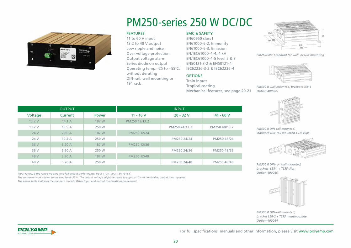
20
For full specifications, manuals and other information, please visit www.polyamp.com
OUTPUT INPUT
Voltage Current Power 11 - 16 V 20 - 32 V 41 - 60 V
13.2 V 14.1 A 187 W PM250 12/13.2
13.2 V 18.9 A 250 W PM250 24/13.2 PM250 48/13.2
24 V 7.80 A 187 W PM250 12/24
24 V 10.4 A 250 W PM250 24/24 PM250 48/24
36 V 5.20 A 187 W PM250 12/36
36 V 6.90 A 250 W PM250 24/36 PM250 48/36
48 V 3.90 A 187 W PM250 12/48
48 V 5.20 A 250 W PM250 24/48 PM250 48/48
EMC & SAFETYEN60950 class IEN61000-6-2, Immunity EN61000-6-3, Emission EN/IEC61000-4-4, 4 kV EN/IEC61000-4-5 level 2 & 3EN50121-3-2 & EN50121-4IEC62236-3-2 & IEC62236-4
OPTIONSTrain inputs Tropical coatingMechanical features, see page 20-21
FEATURES11 to 60 V input 13,2 to 48 V outputLow ripple and noiseOver voltage protection Output voltage alarmSeries diode on outputOperating temp. -25 to +55˚C, without derating DIN-rail, wall mounting or 19" rack
PM250-series 250 W DC/DC
Input range, is the range we gurantee full output performance, Uout +10%, Iout +5% @+55˚.
The converter works down to the stop level -35%. The output voltage might decrease to approx -10% of nominal output at the stop level.
The above table indicates the standard models. Other input and output combinations on demand.
PM500 R wall mounted, brackets L58-1 Option 400065
PM500 R DIN-rail mounted.Standard DIN-rail mounted TS35 clips
PM500 R DIN- or wall-mounted, brackets L58-1 + TS35 clips Option 400065
PM500 R DIN-rail mounted,bracket L58-2 + TS35 mouting plate Option 400064
PM250/500 Standrad for wall- or DIN mounting

21
For full specifications, manuals and other information, please visit www.polyamp.com
OUTPUT INPUT
Voltage Current Power 50 - 150 V 93 - 150 V 100 - 300 V 187 - 300 V
13.2 V 20.0 A 260 W PM260 110C/13.2 PM260 220D/13.2
24 V 20.0 A 500 W PM500 110/24 PM500 220/24
48 V 10.5 A 500 W PM500 110/48 PM500 220/48
110 V 4.50 A 500 W PM500 110/110 PM500 220/110
EMC & SAFETYEN60950 class IEN61000-6-2, Immunity EN61000-6-3, Emission EN/IEC61000-4-4, 4 kV EN/IEC61000-4-5 level 2 & 3EN50121-3-2 & EN50121-4IEC62236-3-2 & IEC62236-4
OPTIONSTrain inputs Tropical coatingMechanical features, see page 20-21
FEATURES50 to 300 V input 13.2 to 110 V output Low ripple and noiseOver voltage protection Output voltage alarmSeries diode on outputOperating temp. -25 to +55˚C, without derating +70˚C derating DIN-rail, wall mounting or 19" rack
PM500-series 500 W DC/DC
PM250/500 R 19" rack. 1) 19” front panel 2 U for two units (option 400062) 2) 19” front panel 2 U for two units with blind panel (option 400062) 3) 19” front panel 6 U for five units (option 400063)4) 19” front panel 6 U for five units with blind panel (option 400063)
Input range, is the range we gurantee full output performance, Uout +10%, Iout +5% @+55˚.
The converter works down to the stop level -35%. The output voltage might decrease to approx -10% of nominal output at the stop level.
The above table indicates the standard models. Other input and output combinations on demand.
PM250/500 Standrad for wall- or DIN mounting

22
For full specifications, manuals and other information, please visit www.polyamp.com
OUTPUT INPUT
Voltage Current Power 10 - 30 V 20 - 60 V 50 - 150 V 90 - 270 V
12 V 18.0 A 216 W PU300A12
12 V 25.0 A 300 W PU300B12 PU300C12 PU300D12
13.8 V 16.0 A 220 W PU300A13.8
13.8 V 21.8 A 300 W PU30B13.8 PU300C13.8 PU300D13.8
15 V 16.0 A 240 W PU300A15
15 V 20.0 A 300 W PU300B15 PU300C15 PU300D15
24 V 10.0 A 240 W PU300A24
24 V 12.5 A 300 W PU300B24 PU300C24 PU300D24
28 V 8.58 A 240 W PU300A28
28 V 10.8 A 300 W PU300B28 PU300C28 PU300D28
36 V 6.67 A 240 W PU300A36
36 V 8.34 A 300 W PU300B36 PU300C36 PU300D36
48 V 5.00 A 240 W PU300A48
48 V 6.25 A 300 W PU300B48 PU300C48 PU300D48
60 V 4.00 A 240 W PU300A60
60 V 5.00 A 300 W PU300B60 PU300C60 PU300D60
EMC & SAFETYEN60950 class IEN61000-6-2, Immunity EN61000-6-3, Emission EN/IEC61000-4-4, 4 kV EN/IEC61000-4-5 level 2 & 3EN50121-3-2 & EN50121-4IEC62236-3-2 & IEC62236-4
OPTIONSTrain inputs Tropical coatingMechanical features, see page 22-23
FEATURESWide input voltage range10 to 270 V input 12 to 60 V outputOver voltage protection Output voltage alarmSeries diode on output Remote sense Inhibit / Power down inputOperating temp. -25 to +55˚C, without derating Wall mounting or 19" rack
PU300-series 300 W DC/DC
PU300/500 wallmounted, L216-1 (optional)
PU300/500 wallmounted. Brackets PL86-1 (standard)
The above table indicates the standard models. Other input and output combinations on demand.

23
For full specifications, manuals and other information, please visit www.polyamp.com
PU500-series 500 W DC/DC EMC & SAFETYEN60950 class IEN61000-6-2, Immunity EN61000-6-3, Emission EN/IEC61000-4-4, 4 kV EN/IEC61000-4-5 level 2 & 3EN50121-3-2 & EN50121-4IEC62236-3-2 & IEC62236-4
OPTIONSSeries diode on output Train inputs Tropical coatingMechanical features, see page 22-23
FEATURES18 to 300 V input 24 to 60 V output Over voltage protection Output voltage alarm Remote sense Inhibit / Power down inputOperating temp. -25 to +55˚C, without derating Wall mounting or 19" rack
OUTPUT INPUT
Voltage Current Power 18 - 32 V 38 - 60 V 88 - 150 V 175 - 300 V
24 V 16.7 A 400 W PU500 24/24
24 V 20.9 A 500 W PU500 48/24 PU500 110/24 PU500 220/24
28 V 14.3 A 400 W PU500 24/28
28 V 17.9 A 500 W PU500 48/28 PU500 110/28 PU500 220/28
36 V 11.2 A 400 W PU500 24/36
36 V 13.9 A 500 W PU500 48/36 PU500 110/36 PU500 220/36
48 V 8.34 A 400 W PU500 24/48
48 V 10.5 A 500 W PU500 48/48 PU500 110/48 PU500 220/48
60 V 6.67 A 400 W PU500 24/60
60 V 8.34 A 500 W PU500 48/60 PU500 110/60 PU500 220/60
PU300/500 19" rack. 1) Brackets L86-3 (optional) 2) 19" rack mounting set (optional) 3) Standard brackets + L480-1 (optional)
PU300/500 wallmounted. Brackets PL86-1 (standard)
The above table indicates the standard models. Other input and output combinations on demand.

For full specifications, manuals and other information, please visit www.polyamp.com
24
FEATURES20 to 300 V input 5 to 125 V output Operating temp. -25 to +70˚C, without deratingTropical coatingEuroformat 10TE to 14TE 6HEDIN-rail, wall mounting or 19” subrack
PSC600-series 800 W DC/DC EMC & SAFETYEN60950 class I EN61000-6-2, Immunity EN61000-6-3, Emission EN/IEC61000-4-4, 4 kV EN/IEC61000-4-5 level 2 & 3EN50121-3-2 & EN50121-4IEC62236-3-2 & IEC62236-4
OPTIONSSeries diode on output Train inputs
OUTPUT INPUT
Voltage Current Power 20 - 32 V 41 - 60 V 93 - 150 V 187 - 300 V
5 V 60.0 A 300 W PSC300 24/5 PSC300 48/5 PSC300 110/5 PSC300 220/5
12 V 33.0 A 400 W PSC400 24/12 PSC400 48/12 PSC400 110/12 PSC400 220/12
12 V 60.0 A 720 W ---- PSC700 48/12 PSC700 110/12 PSC700 220/12
15 V 27.0 A 400 W PSC400 24/15 PSC400 48/15 PSC400 110/15 PSC400 220/15
15 V 54.0 A 800 W ---- PSC800 48/15 PSC800 110/15 PSC800 220/15
24 V 25.0 A 600 W PSC600 24/24 PSC600 48/24 PSC600 110/24 PSC600 220/24
24 V 33.0 A 800 W ---- PSC800 48/24 PSC800 110/24 PSC800 220/24
48 V 12.5 A 600 W PSC600 24/48 PSC600 48/48 PSC600 110/48 PSC600 220/48
48 V 17.0 A 800 W ---- PSC800 48/48 PSC800 110/48 PSC800 220/48
110 V 5.50 A 600 W PSC600 24/110 PSC600 48/110 PSC600 110/110 PSC600 220/110
110 V 7.30 A 800 W ---- PSC800 48/110 PSC800 110/110 PSC800 220/110
125 V 4.80 A 600 W PSC600 24/125 PSC600 48/125 PSC600 110/125 PSC600 220/125
125 V 6.40 A 800 W ---- PSC800 48/125 PSC800 110/125 PSC800 220/125
PSC600-series for 19" subrack mounting, Model with L-panel 10TE, 12TE and 14TE (optional)
PSC600-series for DIN- or wall-mounting, Model with N (std) Model with H15-screw and M6 bolts/studs
Input range, is the range we gurantee full output performance, Uout +10%, Iout +5% @+55˚.
The converter works down to the stop level -35%. The output voltage might decrease to approx -10% of nominal output at the stop level.
The above table indicates the standard models. Other input and output combinations on demand.

25
For full specifications, manuals and other information, please visit www.polyamp.com
OUTPUT INPUT
Voltage Current Power 18 - 32 V 38 - 60 V 50 - 90 V 88 - 150 V 175 - 300 V
24 V 33.4 A 800 W PU1000 24/24
24 V 41.7 A 1000 W PU1000 48/24 PU1000 72/24 PU1000 110/24 PU1000 220/24
28 V 28.6 A 800 W PU1000 24/28
28 V 35.7 A 1000 W PU1000 48/28 PU1000 110/28 PU1000 220/28
48 V 16.7 A 800 W PU1000 24/48
48 V 20.9 A 1000 W PU1000 48/48 PU1000 72/48 PU1000 110/48 PU1000 220/48
60 V 13.4 A 800 W PU1000 24/60
60 V 16.7 A 1000 W PU1000 48/60 PU1000 72/60 PU1000 110/60 PU1000 220/60
85 V 11.8 A 1000 W PU1000 48/85 PU1000 72/85 PU1000 110/85 PU1000 220/85
110 V 7.28 A 800 W PU1000 24/110
110 V 9.09 A 1000 W PU1000 48/110 PU1000 72/110 PU1000 110/110 PU1000 220/110
EMC & SAFETYEN60950 class IEN61000-6-2, Immunity EN61000-6-3, Emission EN/IEC61000-4-4, 4 kV EN/IEC61000-4-5 level 2 & 3EN50121-3-2 & EN50121-4IEC62236-3-2 & IEC62236-4
OPTIONSTrain inputs Tropical coatingMechanical features
FEATURES18 to 300 V input 24 to 110 V output Over voltage protection Output voltage alarmSeries diode on outputRemote sense Inhibit / Power down inputCurrent sharing in parallel mode Operating temp. -25 to +55˚C, without derating Wall mounting or 19" rack
PU1000-series 1000 W DC/DC
PU600/1000 19" rack. 1) Standard brackets L89-1, 19" rack 2) Standard brackets + L480-2 (optional)
PU600/1000 Wallmounted. Brackets L89-1 (standard)
The above table indicates the standard models. Other input and output combinations on demand.
PU1000 has a wide input voltage version with 600 W output power, the PU600-series. Consult www.polyamp.com
PU600/1000 Wallmounted. Brackets L300-1 (optional)

26
For full specifications, manuals and other information, please visit www.polyamp.com
EMC & SAFETYEN60950 class IEN61000-6-2, Immunity EN61000-6-3, Emission EN/IEC61000-4-4, 4 kV EN/IEC61000-4-5 level 2 & 3EN50121-3-2 & EN50121-4IEC62236-3-2 & IEC62236-4
OPTIONSSeries diode on output Train inputs Tropical coatingMechanical features, see page 26-27
FEATURES17 to 300 V input 24 to 48 V output Over voltage protection Output voltage alarm Remote senseCurrent sharing Inhibit / Power down inputInrush current limitConvection cooled Operating temp. -25 to +55˚C, without derating Wall mounting or 19” rack
OUTPUT INPUT
Voltage Current Power 20 - 32 V 43 - 60 V 93 - 150 V 187 - 300 V
24 V 42.0 A 1000 W PC1000 24/24 PC1000 48/24 PC1000 110/24 PC1000 220/24
28 V 36.0 A 1000 W PC1000 24/28 PC1000 48/28 PC1000 110/28 PC1000 220/28
36 V 28.0 A* 1000 W PC1000 24/36 PC1000 48/36 PC1000 110/36 PC1000 220/36
48 V 21.0 A 1000 W PC1000 24/48 PC1000 48/48 PC1000 110/48 PC1000 220/48
PC1000-series 1000 W DC/DC
PC1000/2000 Wallmounted. Brackets L216-1 (optional)
PC1000/2000 Rackmounted 19" 2U. Brackets L89-3 (std)
* NRE might be charged.
Input range, is the range we gurantee full output performance, Uout +10%, Iout +5% @+55˚.
The converter works down to the stop level -35%. The output voltage might decrease to approx -10% of nominal output at the stop level.
The above table indicates the standard models. Other input and output combinations on demand.

27
For full specifications, manuals and other information, please visit www.polyamp.com
EMC & SAFETYEN60950 class IEN61000-6-2, Immunity EN61000-6-3, Emission EN/IEC61000-4-4, 4 kV EN/IEC61000-4-5 level 2 & 3EN50121-3-2 & EN50121-4IEC62236-3-2 & IEC62236-4
OPTIONSSeries diode on output Train inputs Tropical coatingMechanical features, see page 26-27
FEATURES33 to 300 V input 24 to 48 V output Over voltage protection Output voltage alarm Remote senseCurrent sharing Inhibit / Power down inputInrush current limitConvection cooled 1000 W Operating temp. -25 to +55˚C, without derating Wall mounting or 19” rack
OUTPUT INPUT
Voltage Current Power 43 - 60 V 93 - 150 V 187 - 300 V Cooling
24 V 58.0 A 1400 W PC1400 48/24 PC1400 110/24 PC1400 220/24 FAN
28 V 50.0 A 1400 W PC1400 48/28 PC1400 110/28 PC1400 220/28 FAN
36 V 39.0 A* 1400 W PC1400 48/36 PC1400 110/36 PC1400 220/36 FAN
48 V 42.0 A 2000 W PC2000 48/48 PC2000 110/48 PC2000 220/48 FAN
PC2000-series 2000 W DC/DC
PC1000/2000 Rackmounted 19" 2U. Brackets L89-3 (std)
PC1000/2000 19" rack. 1) Standard brackets 2) Standard brackets + L480-2 (optional)
* NRE might be charged.
Input range, is the range we gurantee full output performance, Uout +10%, Iout +5% @+55˚.
The converter works down to the stop level -35%. The output voltage might decrease to approx -10% of nominal output at the stop level.
The above table indicates the standard models. Other input and output combinations on demand.

For full specifications, manuals and other information, please visit www.polyamp.com
28
Military vehicle applications DC/DC converters for Military vehicle applications with MIL-STD 1275D 28 V input and output 12, 24, 48 V for equipment supply and 100 to 150 V for motor drive of moving equipment’s. Continuous output power 500 W with peak current capacity for motor drive applications.MIL-STD 461E high immunity RS103 100 to 200 V/m and low emissions. Case and connection rated IP54.
The DC/DC converter PU300 12/27 and PU500 24/28 supply an insulated stable low noise 28 V for radios used in modified vehicles used by UN troops and fast attack boats.
DC UPS PA356, 12 V fast charging In large storages the handling forklifts are used dur-ing several shifts. Instead of charging the whole forklift vehicle they use interchangeable battery modules. To change such battery it takes some minutes. On the fork-lift, the driver has direct contact with the logistic system via a computer connected to a WiFi network. Those computers use Windows® Operating system and they do not like sudden power down. Polyamp developed together with suppliers of forklift computers a DC UPS that overcome this problem.
The DC-UPS works for about 15 minutes. It use the RS232 standard UPS signaling methods supported by Windows® to switch off the computer in a controlled manner.
The battery is an environmental friendly NiMh. The inte-gral battery charger can fully charge the battery within 2 hours, as many such situations can happen per day. In normal operation it supplies the computer and charge the battery.
Input voltage +18 V 2.7 A Rated power in UPS mode: 30 W 12 V 3 A. (Uout =10.5 V) Stop voltage: 10 V.
PM50B18-18 and PM50C18-18 are optimized to supply the DC-UPS, please see page 12.
Special models
Military vehicle DC/DC converters
DC/DC converter PU300 12/27 DC/DC converter 48/270 Vdc, PSC600 48/135, 2 units in series mode Fire and Smoke
PA355 4 x 12 mA constant current source PA355 is a constant current source with 4 outputs. It is used to supply current to safety relays on train or track-side applications. It automatically compensate for changes in feeding cable lengths up to 4 km. PA355 is able to feed 4 individual relays, with common zero. Each output has surge arrestors as protection.
It also handles a redundant input voltage (110 V) with individual alarms. The voltage source is usually one or two (for redundancy) PM50C60-60, please see page 12.
Iout1= 10 or 12 mA Uout max = 120 V Iout2= 10 or 12 mA Uout min = 40 V Iout3= 10 or 12 mA Uin alarm: Max 30 Vd.c.; 0,1 A Iout4= 10 or 12 mA Ta = -20 to +55°C EMC According to SS4361503 PL5
Railway Smoke & Fire standard EN 45545 The purpose of EN 45545 is that train coaches are de-signed in such a way that passengers have enough time to evacuate in case of emergency. With a small modifica-tion, most of our DC/DC converters falls in the category of “non listed product” of EN45545-5 and by using the installation criteria of EN 45545-2 with < 100 g fire load, they can be installed in a non-fire enclosure environ-ment.

For full specifications, manuals and other information, please visit www.polyamp.com
29
Systems Configurations Polyamp supplies customized power systems with DC/DC converters in 19"-subrack with 3U/3HE or 6U/6HE units. They are based on our Euro cassettes with PSE100 up to PSE250 series with 3HE or PSC600 series with 6HE units.
We use solutions with back planes or complete cabled with connectors. Hot plug-in with DC/DC converters is possible. However as they have to be individually fused at the distribution point, this function is really not rel-evant for DC/DC converters. At high input voltages e.g. 110 Vd.c. its not recommended, even with clever inrush current circuits (that PSC600 uses).
We have specially designed cabinets for railway applica-tions or standard subracks for Telecom, Power plants, Process industry and other applications.
DC Power System Configurations
This figure shows a traditional battery charging system with a batery and battery fuse. After that is the downstream fuse distribution.
A distribution system using power supplies or DC-DC converters without "battery fuse".
Rectangular current limit characteristic of Polyamp DC/DC convertersMixed outputs The photo below shows a system where the outputs are mixed to form a unit that supplies +5 V 20-30 A, ±12V 3 A and +24 V 1.5 A. In this case the Euroformat cassettes are not visible.
Safety Critical SystemsThe photo below is an example of Safety Critical power supply system where 2 different input batteries are used (A and B) with 2 or 3 redundant units per group. All outputs are parallel connected with alarm signalization.
Power supplies or DC/DC blowing fusesThere are two scenarios to blow a fuse; the load has a slow decrease of performance or the load has a sudden short circuit. The later can be a problem for a power supply to generate a peak current enough to blow a fuse. However if the power supply or DC-DC converter supply a single load their own current limit will protect the load, then a "battery fuse" is not needed.
By definition, in a fuse distribution the secondary loads has smaller fuses than the main rated current. If the "downstream" fuses are 1/3 - 1/4 of the total load, the power supply will blow the fuse as wellas a battery does. Therefore it is a question of dimensioning the distribu-tion system correctly.
Safety Critical system, with 2 x N+1 configuration
Multi output system
If the distance is large to the fuse distribution point, a large electrolytic capacitor together with a series diode might be needed. That is also valid for battery supplied systems.

For full specifications, manuals and other information, please visit www.polyamp.com
30
Magnetic signature management
Magnetic and Electric Signature ControlDegaussing systemsModern influence sea mines detect the magnetic dis-turbance of a vessel in the Earth’s Magnetic Field, this is referred to as the vessels magnetic signature. This Signature is the most significant influences of those used to trigger to the mine. To minimize this threat naval vessels are fitted with an on-board Degauss-ing System (DG). The DG reduces the signature with a counter-acting field, generated from a coil system, connected to loop-coil current amplifiers. Typical 90- 95% of the ship’s signature can be neutralized with a well designed 3-dimensional DG system. Polyamp spe-cialize in Advanced Degaussing Systems (ADG), which in general terms means that each coil is individually controlled by one loop coil amplifier (BPAU) and that the coil system is 3-dimensional.
Naval operational priorities have shifted from blue water to brown/shallow water. This means that the threat is increased as ships comes much closer to the influence mines. Better degaussing systems than previ-ously used are therefore now required. The answer to this increased threat is ADG. Polyamp have delivered over 45 DG systems, all of which are computer controlled Advanced Degaussing Systems.
Polyamp offer several types of loop-coil amplifiers for installation on different sizes of vessels. The location of the loop coil amplifiers can either be centralized in racks or morden distributed amplifiers close to the degauss-ing coil. The ADG methodology improves the signature performance and the time and effort needed in ranging relative to a system with only a few large amplifiers.
Remote control from the range office can be achieved, quickly and safely by simply connecting a transceiver to the DG system.
The Polyamp powerful ADG systems enable significant savings on the overall installation cost and weight to be achieved by using less and thinner degaussing coil cables. This is of significant benefit to the shipyard.
The ADG is also ideally suitable for the modern prin-ciples of sectional building of ships. The location of the degaussing system components is very flexible and there is no need of a special dedicated operators console to run the ADG. The console function can be one of many other software applications in any suitable PC worksta-tion onboard the vessel.
Polyamp ADG advantages:• Systems suitable from the smallest vessels up to large air craft carriers
• Turnkey capability including system design, equipment supply and proving trials
• Favourable total ownership cost
• Efficient signature handling with prediction, control and evaluation
• Modular and digital open systems, upgradeable for future threats
• Cost effective procurement
Typical degaussing control unit DCUMagnetometer
Loop coil amplifier (BPAU)
A Polyamp ADG is normally controlled by one or more magnetometers to achieve a low signature. Several fallback control modes are available, including Gyro Geomagnetic map and manual, depending on the sys-tem layout.
With ADG the signature is adjusted by changing loop-coil currents. Worldwide operation can be maintained without the need to change connections at the junction boxes or to check ranging before entering the opera-tional area. The ADG ranging process is much faster, es-pecially when using SWECADE ranging data acquisition and measurement software with coil modeling.

For full specifications, manuals and other information, please visit www.polyamp.com
31
Multi Influence Sensor System UMISS
Polyamp UEP and ELFE Systems - Key features • Carbon Fibre Electrodes - Robust Technology
• Very Low Noise Amplifiers - High Sensitivity
• Salinity Independent - Useable for All Waters Instantaneously
• Inert Sensors - Maintenance Free Without Need for Salt Bridges
• Rapid Deployment - No Operational Delays
• High Reliability - Long Life Expectancy
• 3 Axis Platform Designs - Fixed and Transportable Ranges
UEP and ELFE Measurement SystemsUnderwater Electric Potentials (UEP) are produced by cathodic currents in the ship or submarine hull and also from propeller or other metallic materials in contact with salt water. A ships electric potential signature is therefore generated in a similar way as the magnetic signature. This can also be used as an input or trigger signal in an influence mine. The ships movement also produces a Extra Low Frequency Electric field (ELFE) that can be used for positioning, target evaluating or for reconnaissance.
Polyamp have developed a range of sensors and plat-forms for the measurement of these electric signatures for use in:• Upgrading conventional sea ranges
• Transportable sea ranges
• Reconnaissance, fixed or mobile equipments
• Influence sea mines
All the Polyamp sensors and platforms use a unique and patented Polyamp carbon fibre electrode sensor which is very sensitive. The mechanical robustness, handling and life expectancy of sensors using carbon fibre technol-ogy make it much more versatile for these applications compared to other electrode types.
Polyamp can supply a complete system package with electrodes, very low noise amplifiers, data acquisition, analysis, presentation and documentation with the SWECADE© Range Software Package.
Multi Influence Sensor SystemsUMISS© is a family of Multi Influence Sensors Systems designed to measure Underwater Signatures. UMISS© is designed for use as a single unit or with several UMISS© sensors, combined in a full range application.
The UMISS© Sea Module is equipped with magnetic, electric and pressure sensors and an optionally acoustic sensor. Underwater signatures are measured for fixed & mobile ranging and surveillance applications such as for harbour protection.
Digitalization of sensor data takes place in 24 bits ADC´s and synchronizations and packaging of data in a FPGA plus a Microcontroller. To send the UMISS© digitalized sensor data to shore a special Ethernet cable (copper or optical) is used alternatively encrypted WLAN radio communications. The signature analysis is then made in a PC using a special version of the Polyamp SWECADE© software.
UMISS© is designed for easy deployment from a small workboat with minimized requirement for diver assis-tance. The Sea Module is also equipped with highly ac-curate 2-axis inclination sensor unit. Data from this unit and the static 3-axis magnetic sensor enable compensa-tion for non horizontal positions of the Sea Module to be made during subsequent analysis.
Magnetic and Electric Signature Control

For full specifications, manuals and other information, please visit www.polyamp.com
32
Signature ManagementUnderwater signatures from ships, used for mine-fusing and detection should be known and controlled for each naval vessel before entering a mission.
SWECADE© is a software package for magnetic, electric and pressure signature management. It has been devel-oped in co-operation with FMV (the Swedish Defence Material Administration) to be the main tool in predic-tion, design and evaluation of non-acoustic underwater ship-signatures.
SWECADE© has been used at all Swedish ranges (Sea and land) since 1995 and, in its present version, it is also adapted for transportable/moveable ranges.
SWECADE© runs on any standard PC using Windows operating system and can read sensor values from a file or use ADC-boards for data acquisition.
The three modules in SWECADE© are:The component signature prediction module offers:• The calculated magnetic signature at any depth and ambient field
• Modular build up of whole ship set of components (engines, gears etc.)
The loop-coil design package features:
• Design of loop-coils for components, a ship or a ship class
• 3D graphic displays of cable routes
• Prediction of coil-effects at any distance
The range utilities are optimized for:• Signal processing and data management
• Quick, semi-automatic, coil prediction and definition of optimum settings
• Powerful display and print routines
• Built in training for operators and degaussing technicians
"SWECADE© Software, the optimal tool for electromagnetic signature management!"
Signatures in the realityDuring the years SWECADE© has been used for signatures predictions and ranging on both larger and smaller steel hulled vessles, submarines and MCMV's projects with very successful results.
With features to the able to use a syntesis of both real meauserments results in combination with predictions results the SWECADE© softer to has proved to be a very useful, precise and acurate tool in the electric magnetic signature magnagement area.
A FFT software module to SWECADE© can also perform frequency analysis of both electric and magnetic signa-tures as well as pressure and acoustic signatures. Differ-ent FFT windows, filtering functions and more are made available in this software module.
Magnetic and Electric Signature Control
SWECADE© screenshot
SWECADE© FFT Software module

For full specifications, manuals and other information, please visit www.polyamp.com
33
Representative Signature Control Projects performed by POLYAMP
MSS 2000© ships profilerRSwN ELFE Range, Sweden Various Internal projectsGOA ELFE Range, IndiaDGA GESMA, France
DCNS, France
Magnetic and Electric Sweep Supply Influence sea mines detect different parameters and the prime trigging parameter is normally the magnetic sig-nature. Modern mines may also use Underwater Electric Potential (UEP) fields as a trigger. Influence minesweep-ing replicates ships-like signatures of the magnetic and electric influences that will trigger the modern sea mine. Specialized low signature MCM vessels, or remote con-trolled vessels, performing minesweeping are equipped with a mine sweep power supply system and a towed mine sweep load simulating the target signature.
The Polyamp MSS2000 Mine sweep supply system has a modular design with several power modules which sup-ply multiple sweep loads forming the active target signa-ture. Sweep loads can be modular magnetic coils, acous-tic generators, UEP sweep etc. The MSS2000 can also add an AC stray field to form a full ship-like signature with both DC and AC field. Together with the Polyamp Sweep Profiler software package, ship-like signatures can be simulated by the mine sweep. Generated sweep signa-tures are software controlled and a new target signature can be selected at any moment. Swept route effect data can be transferred to the ships command and control system enabling swept route evaluation in real time.
Magnetic and Electric Signature Control
Visby ClassLandsort Class
Stockholm Class
Göteborg ClassGotland Class
Bedok Class
Challanger Class
Absalon Class Ivar Huitfeldt Class
Knut Rasmussen Class
MSD Class
LPD 17 San Antonio Class
CVN 77 Carrier
RSwN, Sweden RSN, Singapore
RD, Denmark USN, USA
Ships projects
Sensor projects
Styrsö Class

For full specifications, manuals and other information, please visit www.polyamp.com
34
About PolyampThe Systems Division of Polyamp specializes in the design, manufacture and supply of Underwater Electromagnetic Signature Management and Control Systems for Worldwide application within the International Naval Industry / International Navy authorities.
The type of systems supplied are Advanced Degaussing systems for surface and submarine naval vessels. Electromagnetic Mine Sweep supply, Underwater Electric Potential (UEP/ELFE) sensors and electromagnetic design and measurment systems.
The SWECADE software can predict and design coil systems, dimension Degaussing systems, control fixed and movable ranges, support signature analyze and document the fleet vessels signature history.
Polyamp Power division specializes in design and production of mainly DC/DC converters and some compatible Power supplies. Our DC/DC converters are used in applications demanding high reliability in rough environments. Thru the years countless applications in sectors like Railway, Energy, Process control, Vehicles, Military, Radio and Telecom etc.
We provide our DC/DC converters to customers worldwide, with an established sales distributor network or directly where we do not have a distributor. Polyamp have three locations; the head office in Sollentuna suburb to Stockholm, Sweden. We have design and manufacturing of DC/DC converters in Åtvidaberg 230 km south of Stockholm and La Chaux-de-Fonds in Switzerland.
Our DC/DC converters have practical MTBF > 1 Million hours and our official warranty is two years. However in case we discover a fault due to workmanship the warranty is much longer than that. We have no dedicated service department as we have worked with quality assurance methods since end of 1980-ties. Our delivery accuracy is around 98% on time, in a day to day basis and delivers to just-in-time schemes. Our quality system is approved for Nuclear Plants Class 1E.

For full specifications, manuals and other information, please visit www.polyamp.com
35

HEAD OFFICEPolyamp AB Box 925 SE-191 29 Sollentuna Sweden Phone: +46 8 594 693 00 Telefax: +46 8 594 693 05
SALES OFFICES Polyamp AB Box 229 SE-597 25 Åtvidaberg Sweden Phone: +46 120 854 10 Telefax: +46 120 854 05
Email: [email protected]
Switch Craft S.A Ruel bel Air 63 CH-2300 La Chaux-de-fondsSwitzerland Phone: +41 32 96 78800Telefax: +41 32 96 78809
Distributor
Catalogue Version 9.1