Embed Size (px)
Citation preview
PNEUMATIC CONTROL
Mohamad Maaroff Bahurdin019 4708987
Pneumatic Control 2
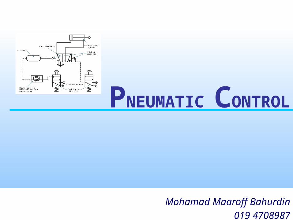
Contents•C
haracteristics and applications of pneumatics
1
•Components of a pneumatic system
2
•Symbols and standards in pneumatics
3
•Basic Pneumatic Circuit
4
•Automation & Principle of Pneumatic Diagram
5
1 Characteristics and Applications of
Pneumatics
Pneumatic Control 4
Pneumatics
• is the use of pressurized air to effect mechanical motion.
• Commonly is used in industry.• It also has applications in among other
things, dentistry, construction, and mining. • Pneumatic power users need not worry
about hazardous leakages as the fuel is commonly just air.
Pneumatic Control 5
Pneumatics in review
• Played an important role as a technology in the performance of mechanical work.
• The technological progress made in material, design and production processes has further improved the quality and diversity of pneumatic components and thereby contributed to their widely spread use in automation.
Pneumatic Control 6
Pneumatics in review (cont.)
• The pneumatic cylinder has a significant role as a linear drive unit, due to its– relatively low cost– ease of installation– simple and robust construction– ready availability in various sizes and
stroke lengths.
Pneumatic Control 7
Pneumatics in review (cont.)
• The pneumatic cylinder has the following general characteristics:– Diameters 2.5 to 320 mm– Stroke lengths 1 to 2000 mm– Available forces 2 to 45000 N at 6 bar– Piston speed 0.1 to 1.5 m/s
Pneumatic Control 8
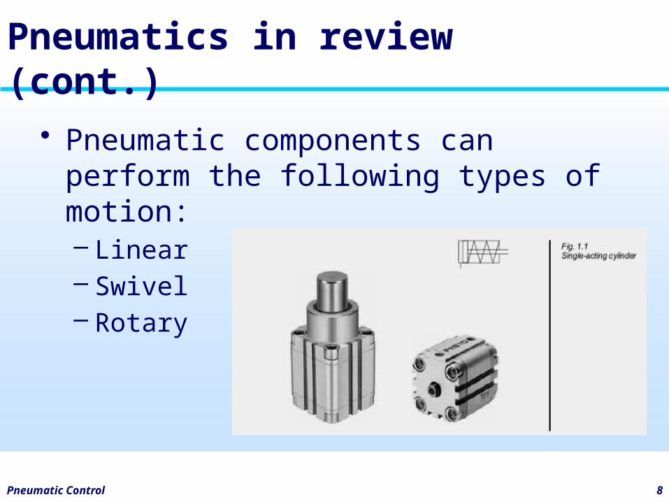
Pneumatics in review (cont.)
• Pneumatic components can perform the following types of motion:– Linear– Swivel– Rotary
Pneumatic Control 9
Pneumatic Application
• Some industrial applications employing pneumatics are listed below:– General methods of material handling:
• Clamping• Shifting• Positioning• Orienting• Branching of material flow
Pneumatic Control 10
Pneumatic Application
– General applications:• Packaging• Filling• Metering• Locking• Driving of axes• Door or chute control• Transfer of materials• Turning and inverting of parts• Sorting of parts• Stacking of components• Stamping and embossing of components
Pneumatic Control 11
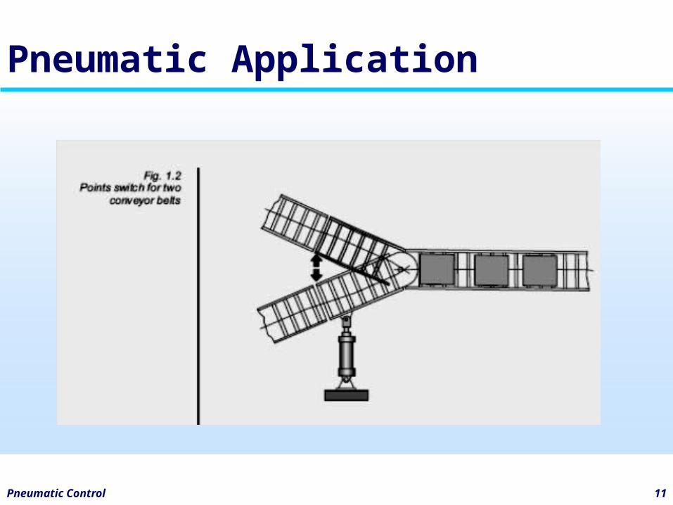
Pneumatic Application
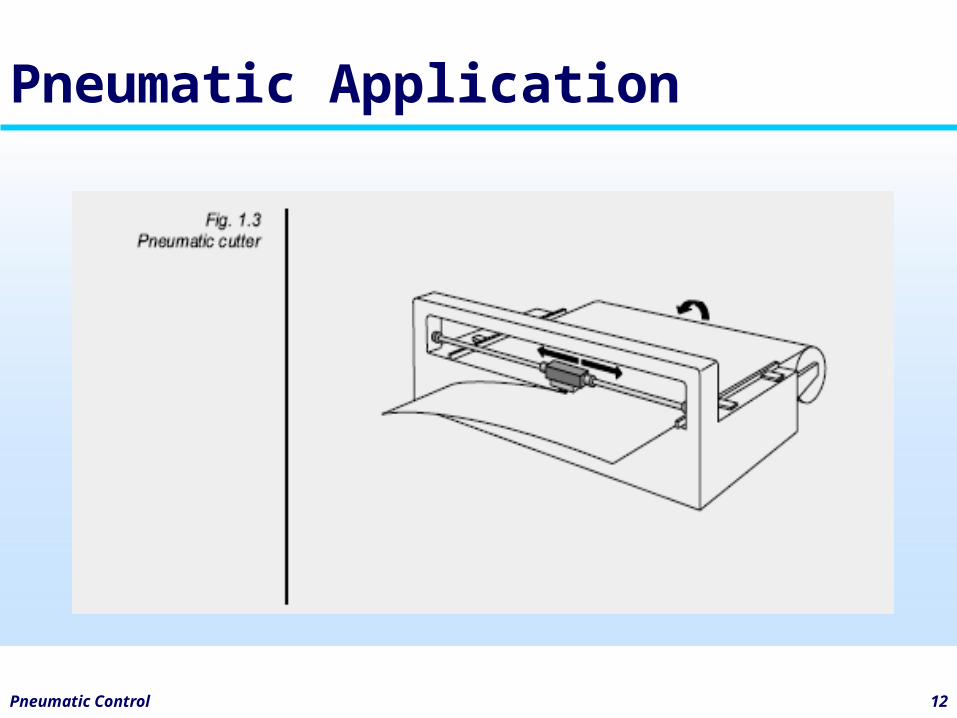
Pneumatic Control 12
Pneumatic Application
Pneumatic Control 13
Pneumatic Application
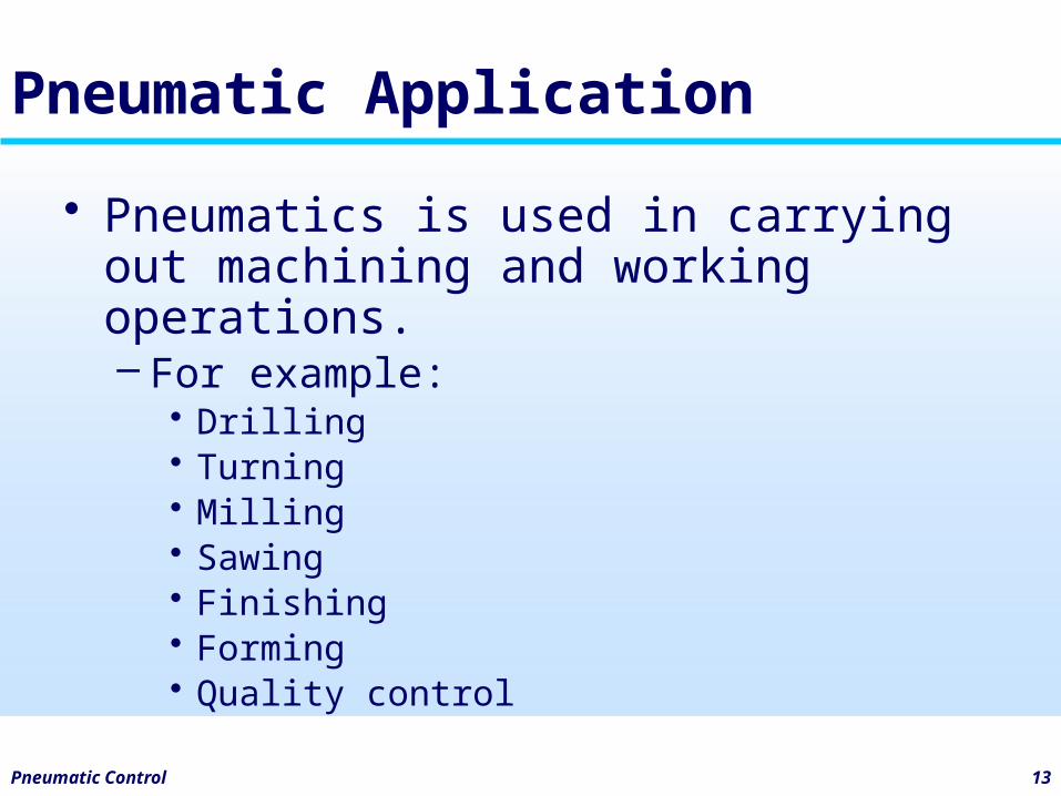
• Pneumatics is used in carrying out machining and working operations.– For example:
• Drilling• Turning• Milling• Sawing• Finishing• Forming• Quality control
Pneumatic Control 14
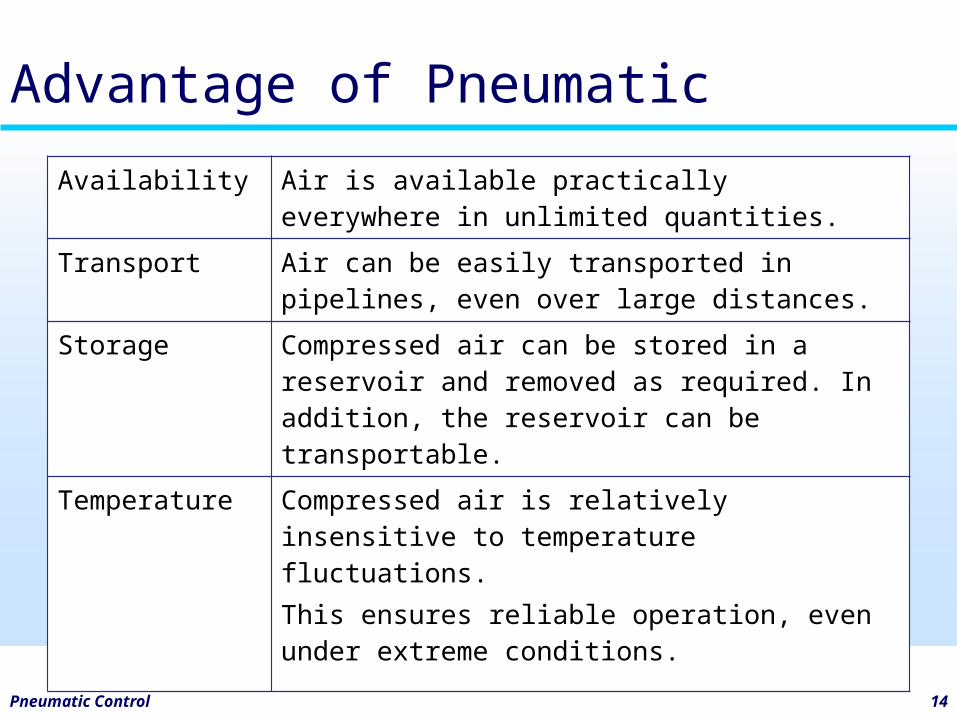
Advantage of Pneumatic
Availability Air is available practically everywhere in unlimited quantities.
Transport Air can be easily transported in pipelines, even over large distances.
Storage Compressed air can be stored in a reservoir and removed as required. In addition, the reservoir can be transportable.
Temperature Compressed air is relatively insensitive to temperature fluctuations.This ensures reliable operation, even under extreme conditions.
Pneumatic Control 15
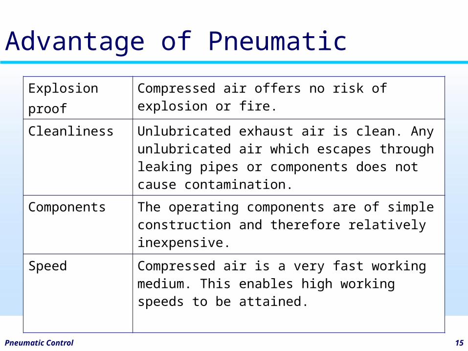
Advantage of Pneumatic
Explosionproof
Compressed air offers no risk of explosion or fire.
Cleanliness Unlubricated exhaust air is clean. Any unlubricated air which escapes through leaking pipes or components does not cause contamination.
Components The operating components are of simple construction and therefore relatively inexpensive.
Speed Compressed air is a very fast working medium. This enables high working speeds to be attained.
Pneumatic Control 16
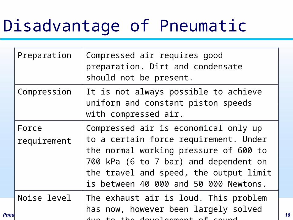
Disadvantage of Pneumatic
Preparation Compressed air requires good preparation. Dirt and condensate should not be present.
Compression It is not always possible to achieve uniform and constant piston speeds with compressed air.
Forcerequirement
Compressed air is economical only up to a certain force requirement. Under the normal working pressure of 600 to 700 kPa (6 to 7 bar) and dependent on the travel and speed, the output limit is between 40 000 and 50 000 Newtons.
Noise level The exhaust air is loud. This problem has now, however been largely solved due to the development of sound absorption material and silencers.
Pneumatic Control 17
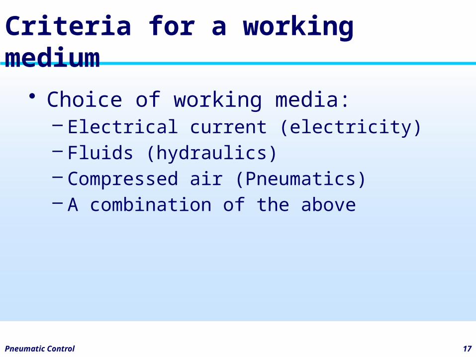
Criteria for a working medium
• Choice of working media:– Electrical current (electricity)– Fluids (hydraulics)– Compressed air (Pneumatics)– A combination of the above
Activity
1. Give another examples of pneumatic application.
2. Is it suitable to use it at home i.e. home appliance? Why?
Pneumatic Control 18
Pneumatic Control 19
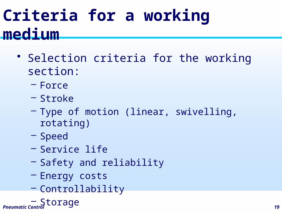
Criteria for a working medium
• Selection criteria for the working section: – Force– Stroke– Type of motion (linear, swivelling, rotating)– Speed– Service life– Safety and reliability– Energy costs– Controllability– Storage
Pneumatic Control 20
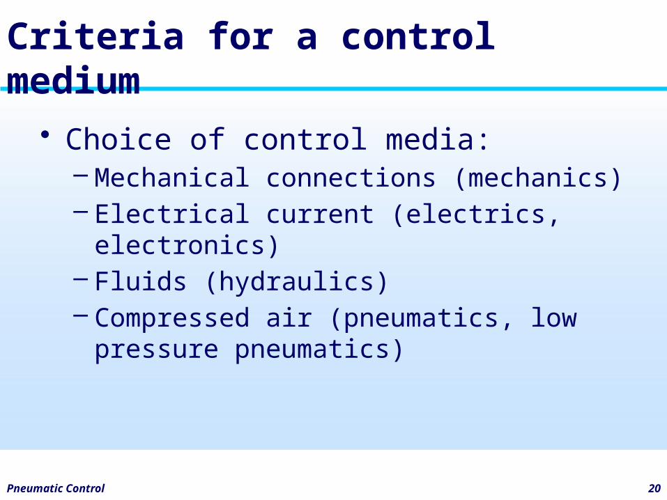
Criteria for a control medium
• Choice of control media:– Mechanical connections (mechanics)– Electrical current (electrics, electronics)– Fluids (hydraulics)– Compressed air (pneumatics, low
pressure pneumatics)
Pneumatic Control 21
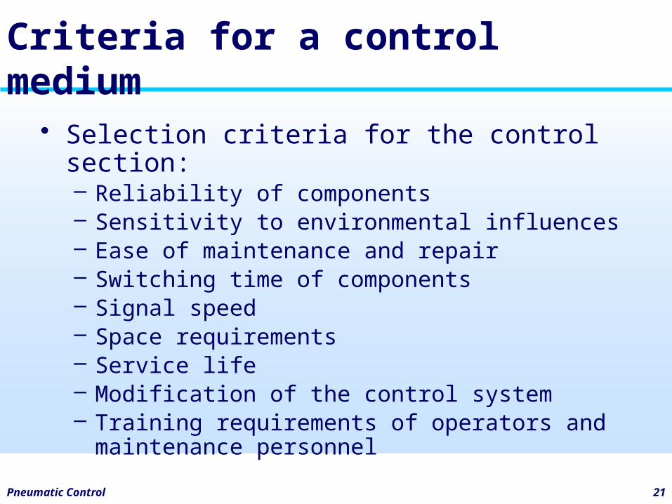
Criteria for a control medium
• Selection criteria for the control section:– Reliability of components– Sensitivity to environmental influences– Ease of maintenance and repair– Switching time of components– Signal speed– Space requirements– Service life– Modification of the control system– Training requirements of operators and
maintenance personnel
Pneumatic Control 22
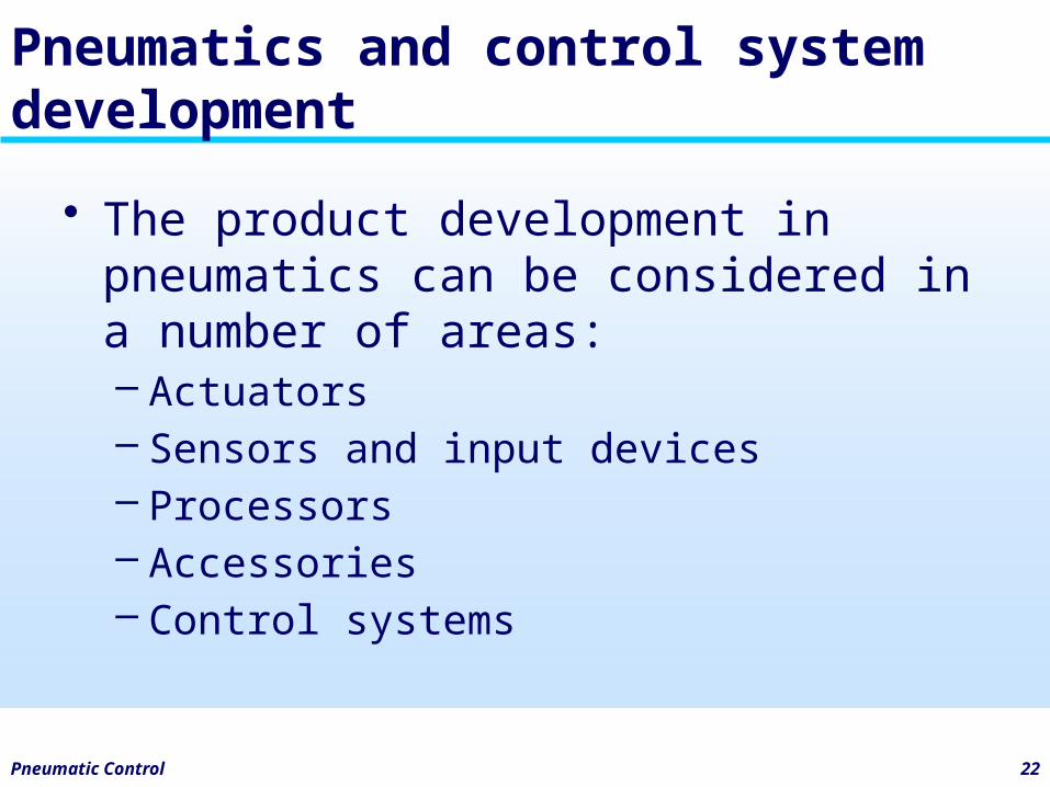
Pneumatics and control system development
• The product development in pneumatics can be considered in a number of areas:– Actuators– Sensors and input devices– Processors– Accessories– Control systems
Pneumatic Control 23
Pneumatics and control system development
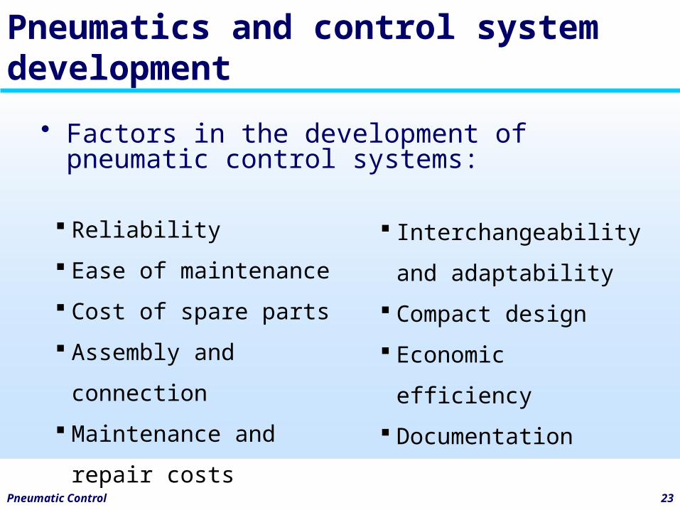
• Factors in the development of pneumatic control systems:
Reliability
Ease of maintenance
Cost of spare parts
Assembly and connection
Maintenance and repair
costs
Interchangeability and
adaptability
Compact design
Economic efficiency
Documentation
Pneumatic Control 24
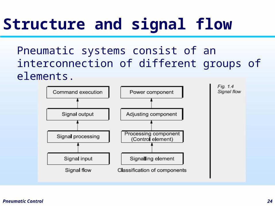
Structure and signal flow
Pneumatic systems consist of an interconnection of different groups of elements.
Pneumatic Control 25
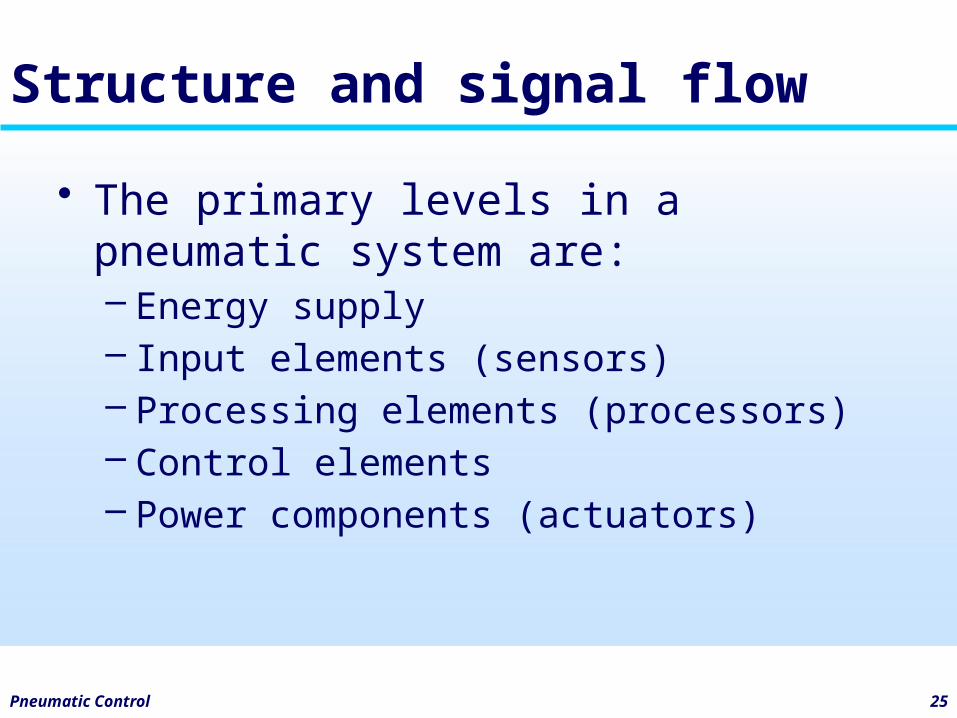
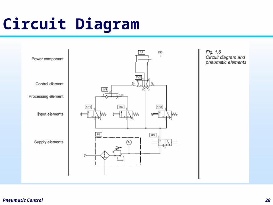
Structure and signal flow
• The primary levels in a pneumatic system are:– Energy supply– Input elements (sensors)– Processing elements (processors)– Control elements– Power components (actuators)
Pneumatic Control 26
Structure and signal flow
• The elements in the system are represented by symbols which indicate the function of the element.
Pneumatic Control 27
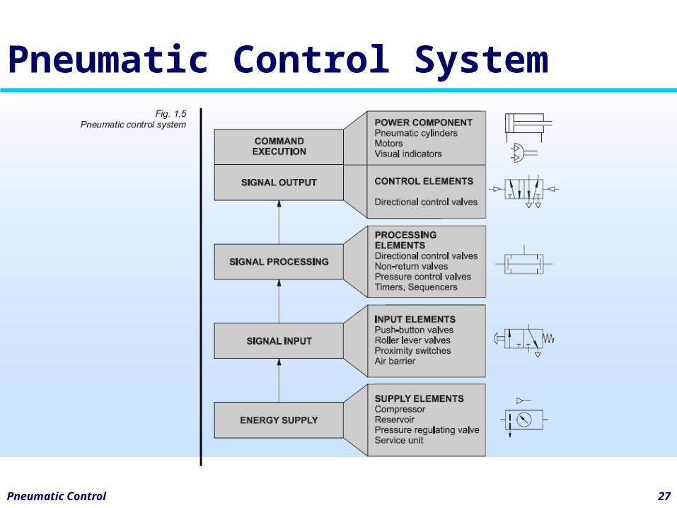
Pneumatic Control System
Pneumatic Control 28
Circuit Diagram
Activity
• Define the terms below:– Actuators– Sensors– Signal input / output– Control diagram / element
Pneumatic Control 29
2Components of a pneumatic system
Pneumatic Control 31
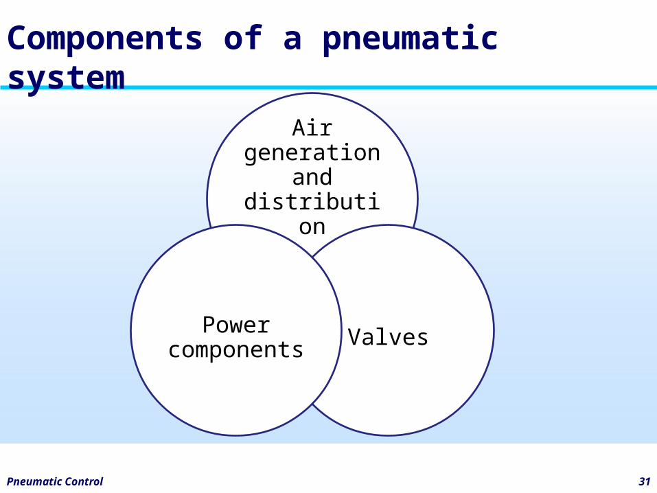
Components of a pneumatic system
Air generation
and distribution
ValvesPower
components
Pneumatic Control 32
Air generation and distribution
• The compressed air should be adequately calculated and made available in the appropriate quality.
• Air is compressed by the air compressor and delivered to an air distribution system in the factory.
• Air service equipment is utilized to prepare the air before being applied to the control system.
Pneumatic Control 33
Air generation and distribution
• Maximum operating pressure is 800-1000 kPa (8 - 10 bar) but in practice it is recommended to operate at between 500-600 kPa (5 and 6 bar) for economic use.
• Due to the pressure losses in the distribution system the compressor should deliver between 650-700 kPa (6.5 and 7 bar) to attain these figures.
Pneumatic Control 34
Air generation and distribution
• A reservoir (receiver) should be fitted to reduce pressure fluctuations.
• The compressor fills the reservoir which is available as a storage tank.
Pneumatic Control 35
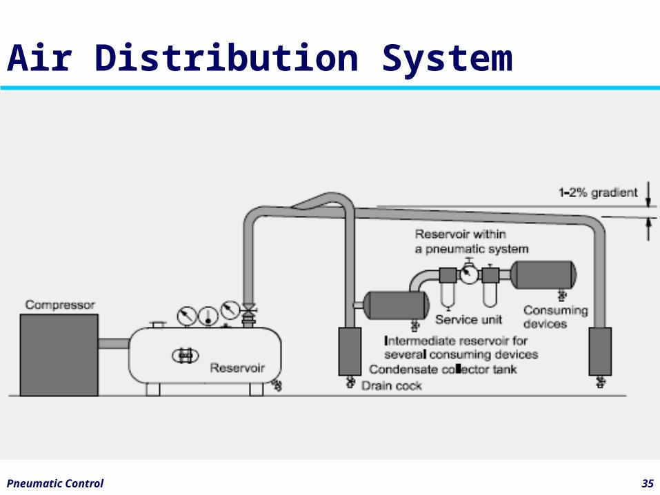
Air Distribution System
Pneumatic Control 36
Air generation and distribution
• The air service unit is a combination of the following :– Compressed air filter (with water
separator)– Compressed air regulator– Compressed air lubricator
• Known as FRL unit
Pneumatic Control 37
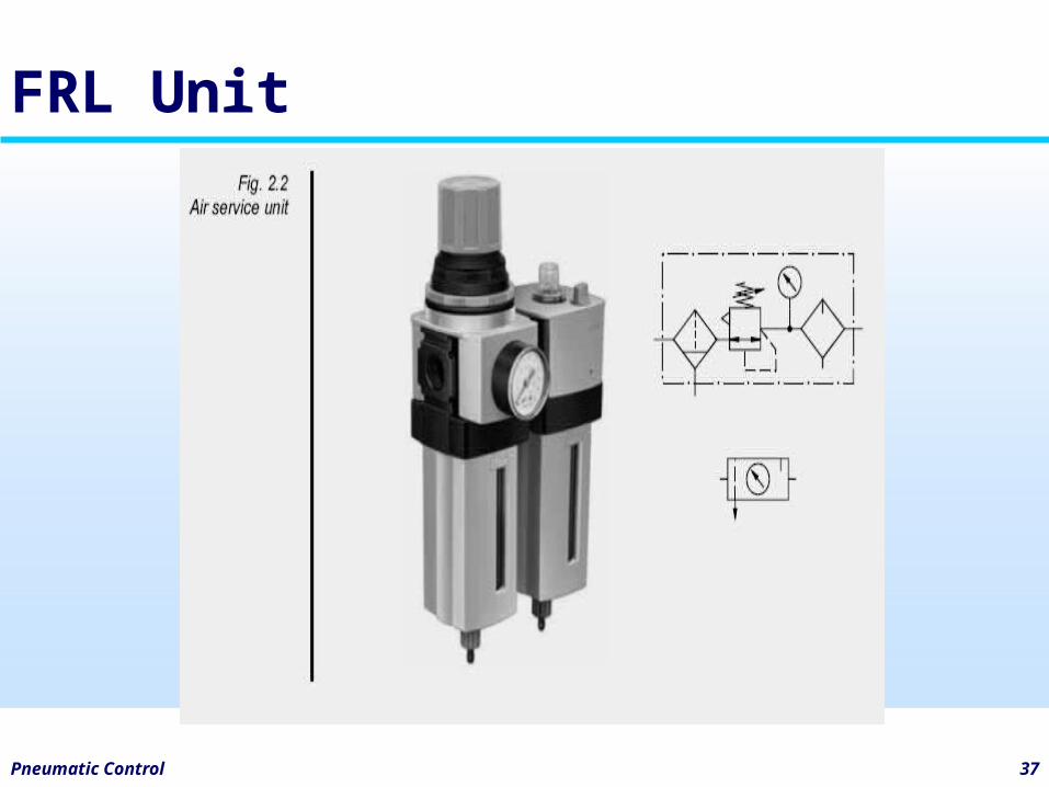
FRL Unit
Pneumatic Control 38
Valves
• To control the pressure or flow rate of pressure media. Depending on design, these can be divided into the following categories:
– Directional control valves– Input/signaling elements– Processing elements– Control elements– Non-return valves– Flow control valves– Pressure control valves
Pneumatic Control 39
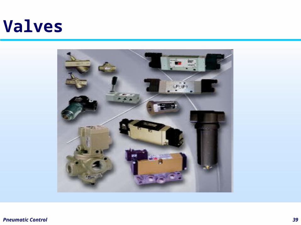
Valves
Pneumatic Control 40
Power components
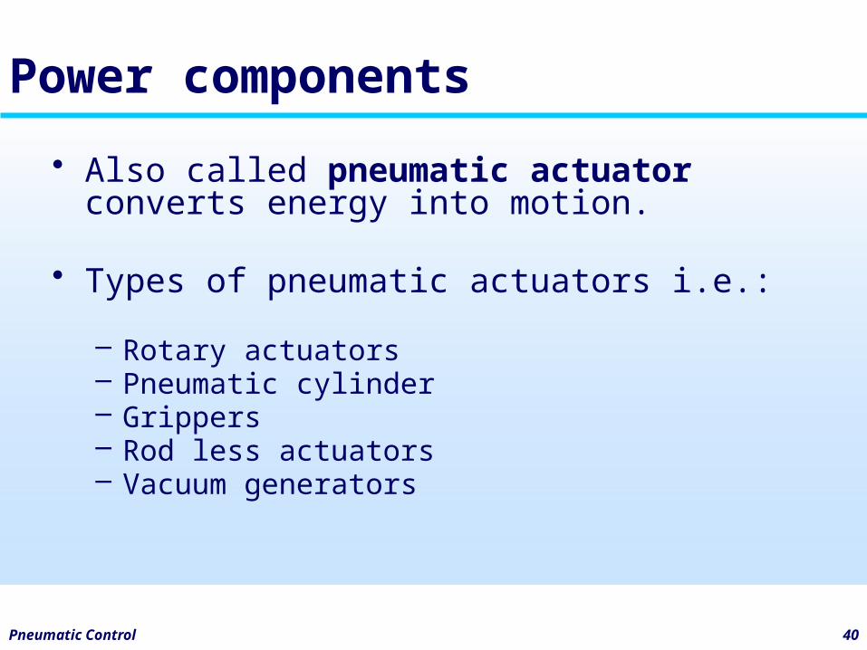
• Also called pneumatic actuator converts energy into motion.
• Types of pneumatic actuators i.e.:
– Rotary actuators– Pneumatic cylinder– Grippers– Rod less actuators– Vacuum generators
Pneumatic Control 41
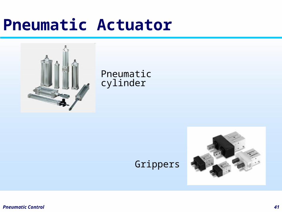
Pneumatic Actuator
Grippers
Pneumatic cylinder
Activity
• Discuss about others power components.
Pneumatic Control 42
3 Symbols and standards in pneumatics
Pneumatic Control 44
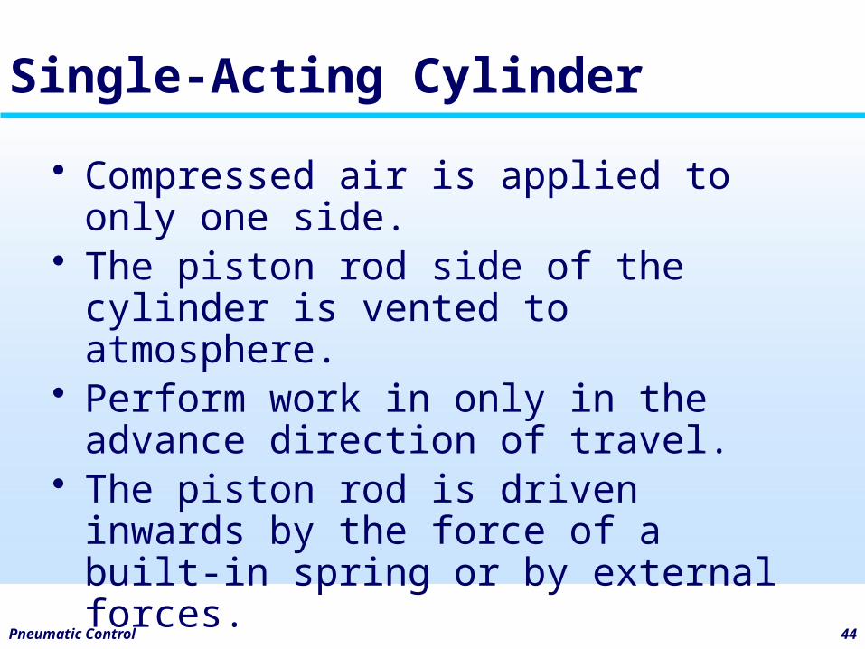
Single-Acting Cylinder
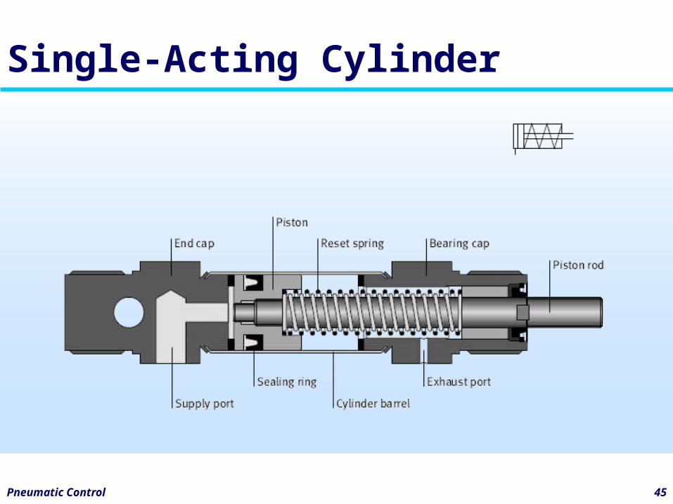
• Compressed air is applied to only one side.
• The piston rod side of the cylinder is vented to atmosphere.
• Perform work in only in the advance direction of travel.
• The piston rod is driven inwards by the force of a built-in spring or by external forces.
Pneumatic Control 45
Single-Acting Cylinder
Pneumatic Control 46
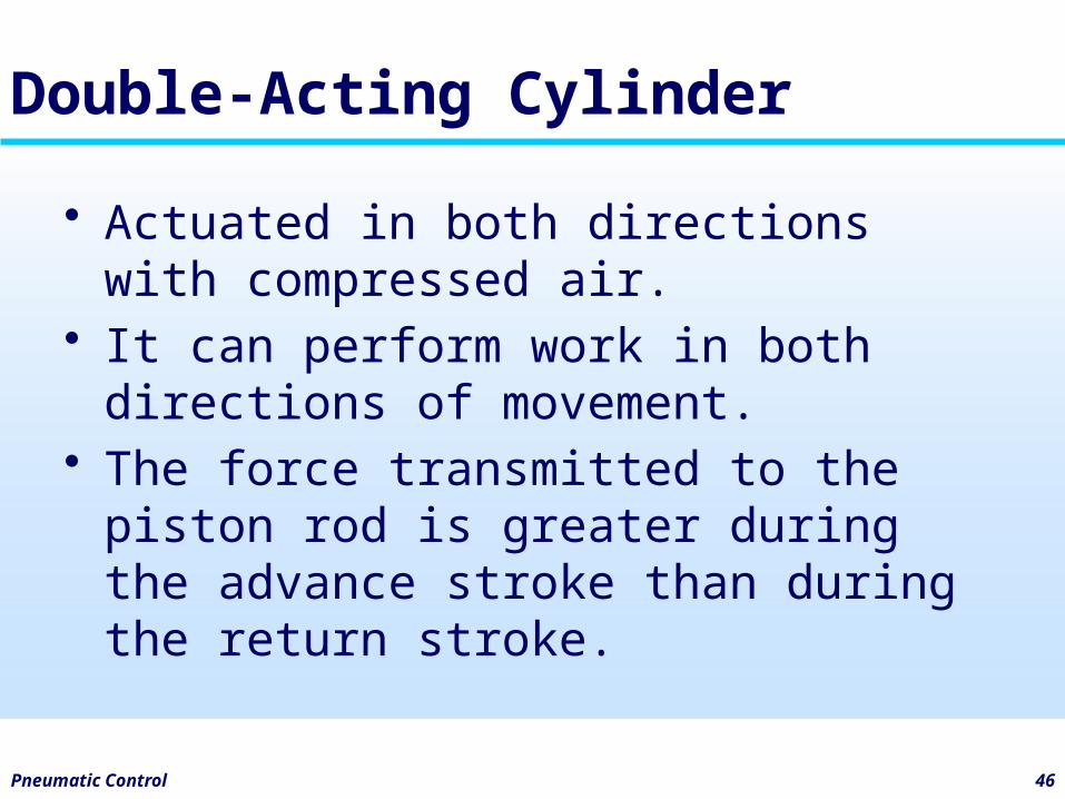
Double-Acting Cylinder
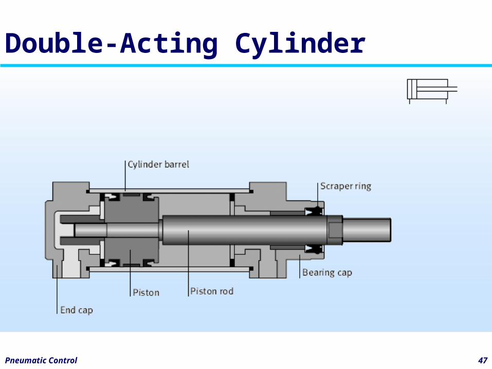
• Actuated in both directions with compressed air.
• It can perform work in both directions of movement.
• The force transmitted to the piston rod is greater during the advance stroke than during the return stroke.
Pneumatic Control 47
Double-Acting Cylinder
Pneumatic Control 48
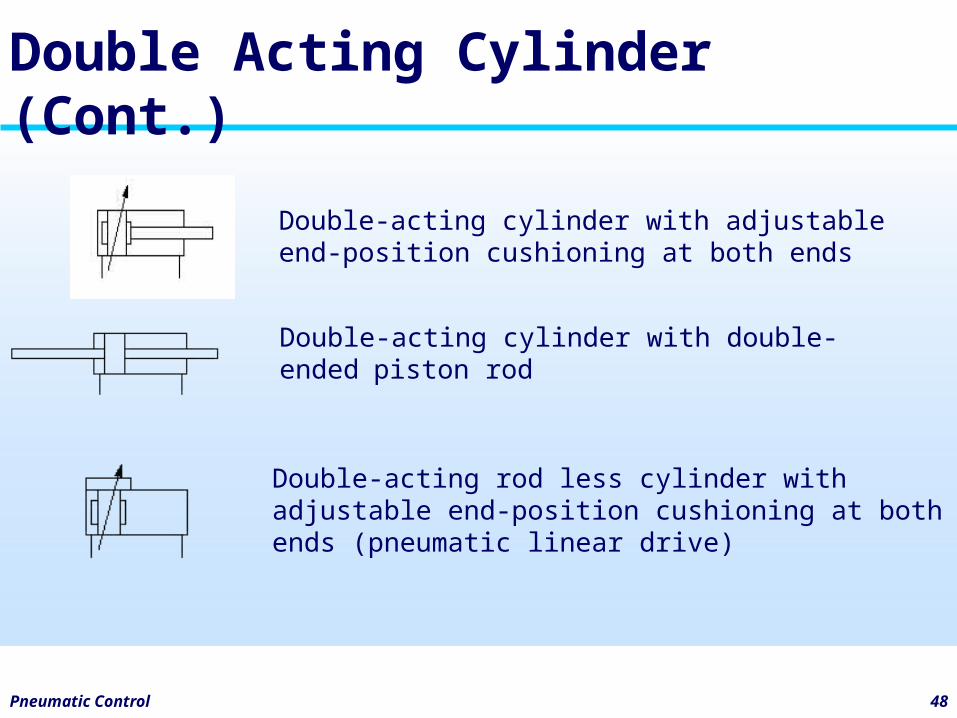
Double Acting Cylinder (Cont.)
Double-acting cylinder with adjustable end-position cushioning at both ends
Double-acting cylinder with double-ended piston rod
Double-acting rod less cylinder with adjustable end-position cushioning at both ends (pneumatic linear drive)
Pneumatic Control 49
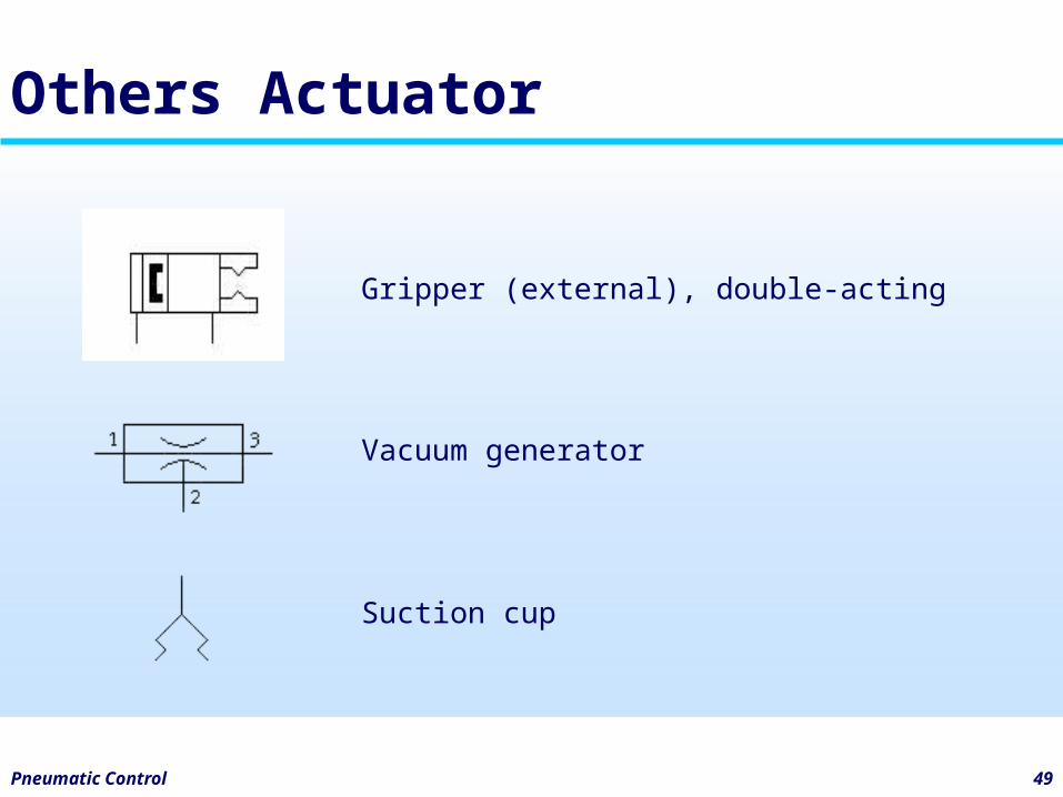
Others Actuator
Gripper (external), double-acting
Vacuum generator
Suction cup
Pneumatic Control 50
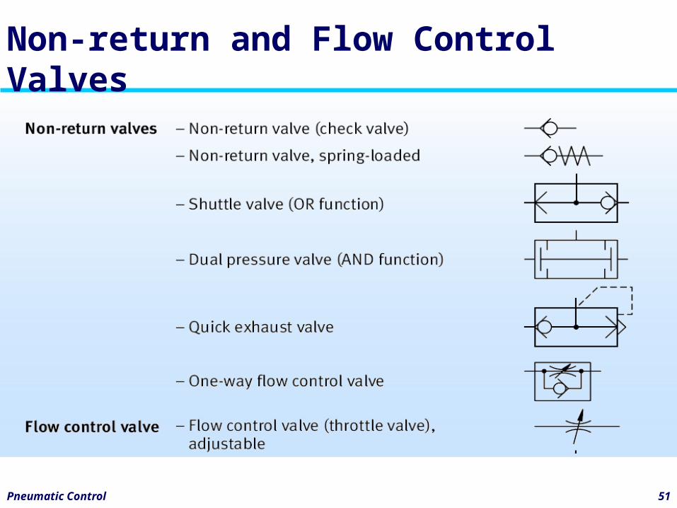
Non-return and Flow Control Valves
• Non-return valves block the flow in one direction and release it in the opposite direction. A distinction is made between:– Non-return valves– Shuttle valves (OR)– Dual pressure valves (AND)– One-way flow control valves– Quick exhaust valves
Pneumatic Control 51
Non-return and Flow Control Valves
Pneumatic Control 52
Pressure Control Valves
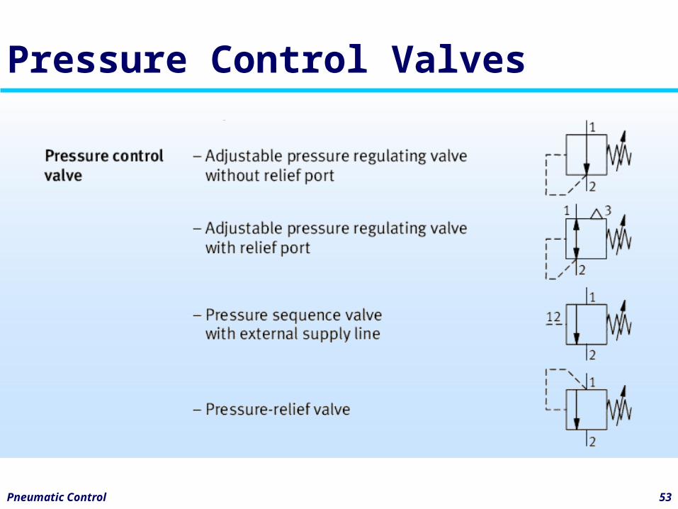
• Pressure control valves influence the pressure or are controlled through the size of the pressure. A distinction is made between:– Pressure regulating valves– Pressure relief valves– Pressure sequence valves
Pneumatic Control 53
Pressure Control Valves
Pneumatic Control 54
Switching Symbols for Valves
• Pneumatic components are normally shown in the deenergized condition in circuit diagrams.
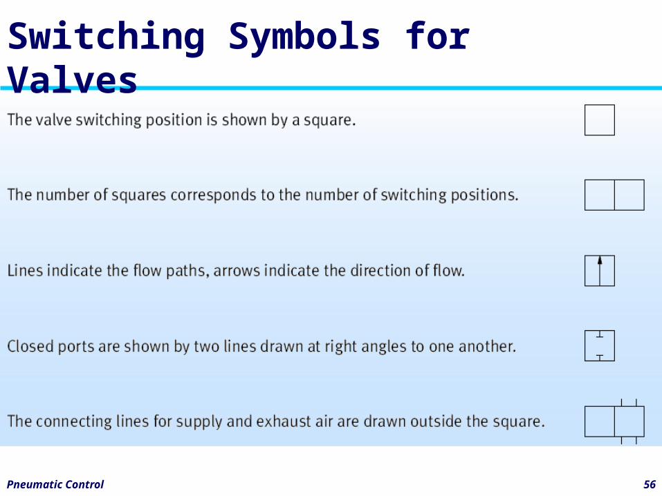
• Valve switching positions are represented by a square.
• The number of squares corresponds to the number of switching positions.
Pneumatic Control 55
Switching Symbols for Valves
• Functions and modes of operation are drawn inside the square:– Lines indicate the flow paths.– Arrows indicate the flow direction.– Closed ports are represented by two
lines drawn at right angles to one another.
• The connecting lines are drawn outside on the square.
Pneumatic Control 56
Switching Symbols for Valves
Pneumatic Control 57
Directional Control Valves
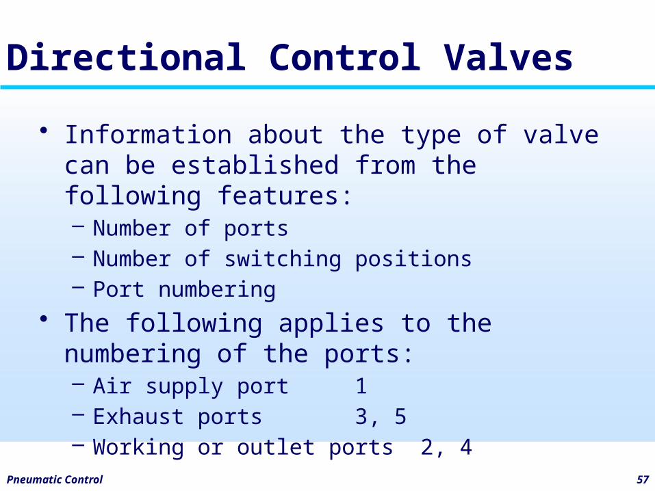
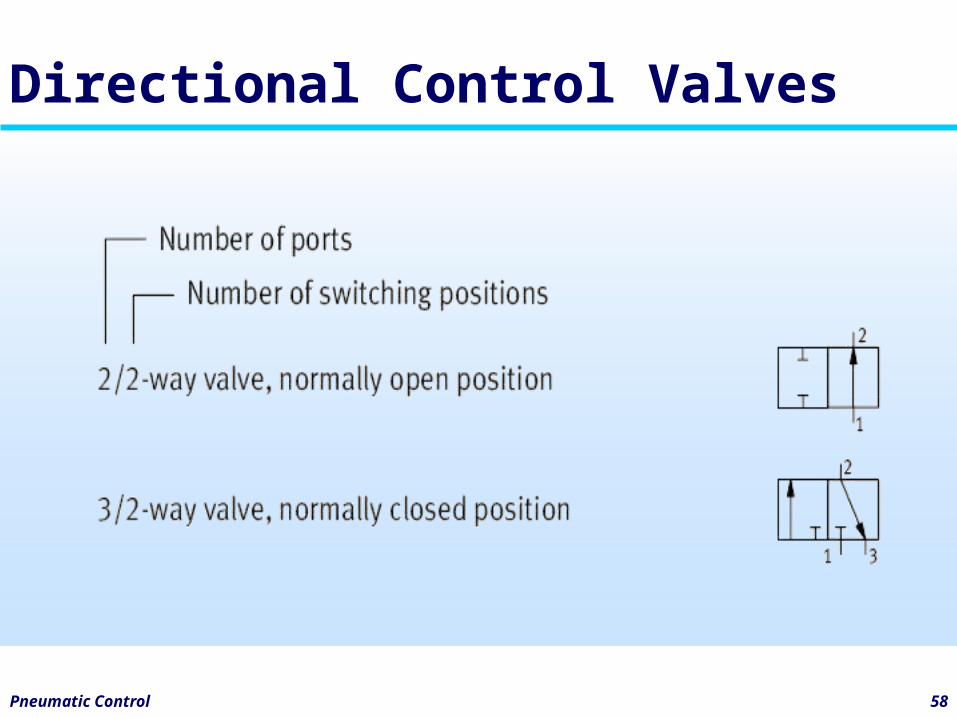
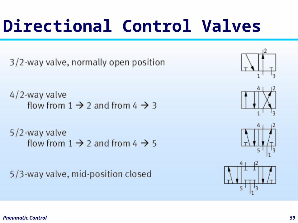
• Information about the type of valve can be established from the following features:– Number of ports– Number of switching positions– Port numbering
• The following applies to the numbering of the ports:– Air supply port 1– Exhaust ports 3, 5– Working or outlet ports 2, 4
Pneumatic Control 58
Directional Control Valves
Pneumatic Control 59
Directional Control Valves
Pneumatic Control 60
Types of DCV actuation
• The following information is required in order to fully represent a directional control valve in a pneumatic circuit diagram:– Basic type of valve actuation– Reset method– Pilot control (if applicable)– Additional forms of actuation (such as
manual override, if available)
Pneumatic Control 61
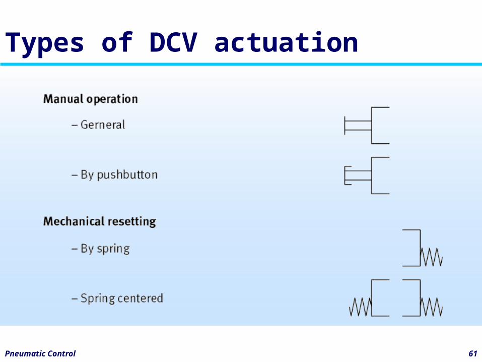
Types of DCV actuation
Pneumatic Control 62
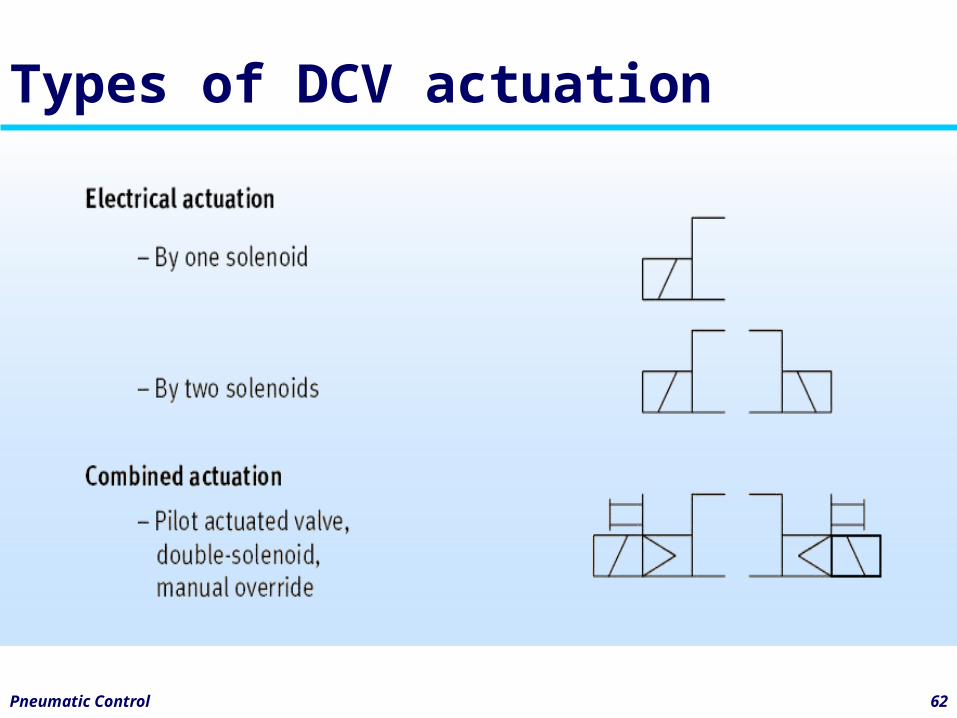
Types of DCV actuation
Pneumatic Control 63
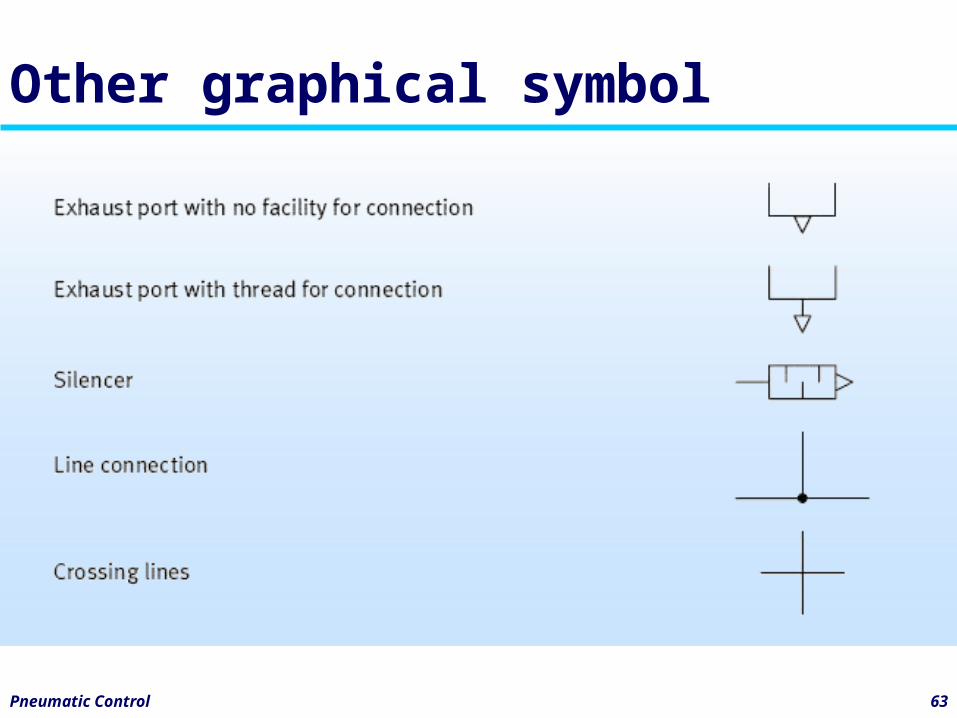
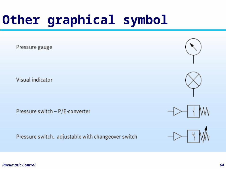
Other graphical symbol
Pneumatic Control 64
Other graphical symbol
Pneumatic Control 65
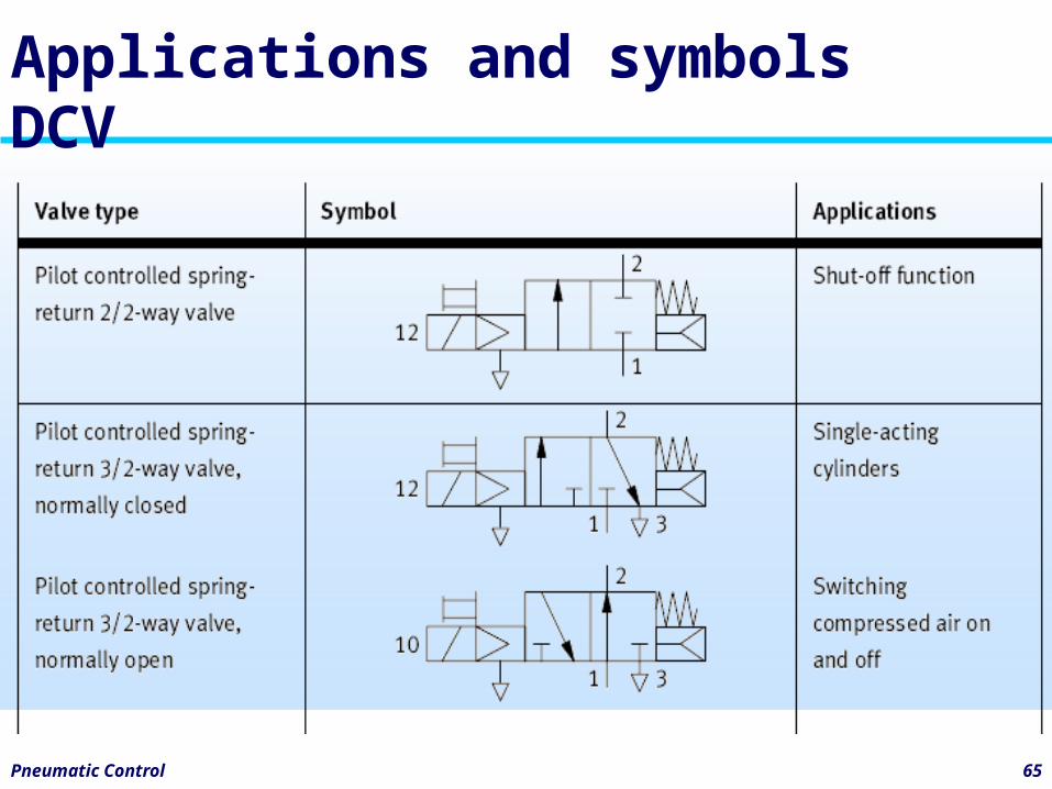
Applications and symbols DCV
Pneumatic Control 66
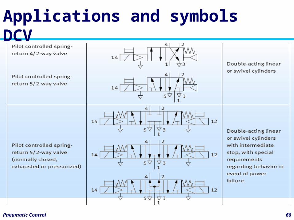
Applications and symbols DCV
Pneumatic Control 67
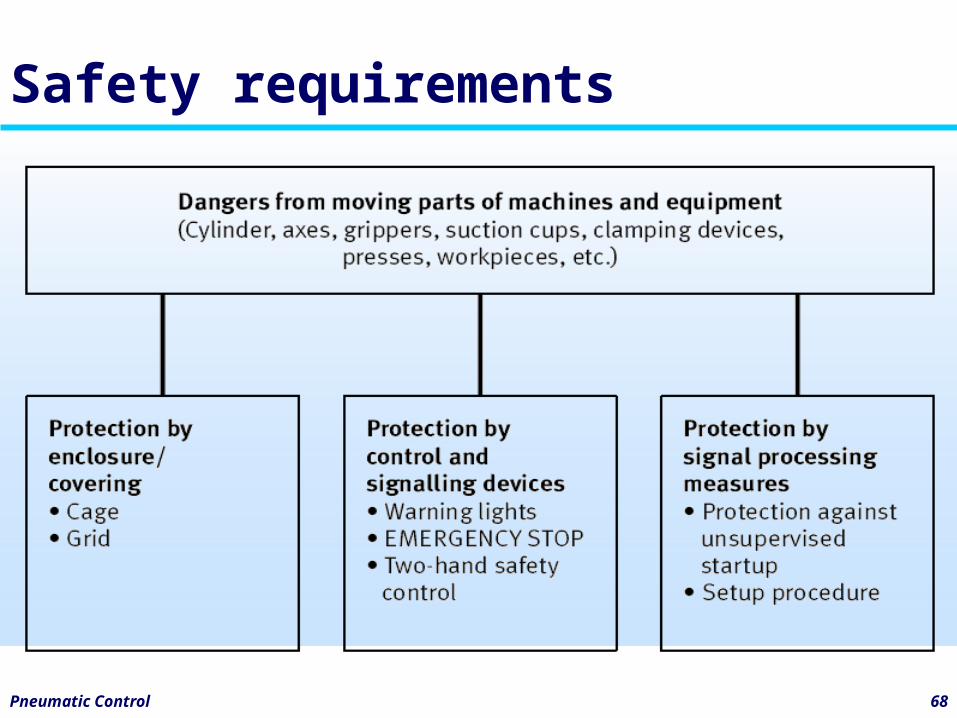
Safety requirements
• Dangers and protective measures• One source of danger is moving parts
of machines and equipment. • On a pneumatic press, for example,
care must be taken to prevent the operator's fingers or hands from being trapped.
Pneumatic Control 68
Safety requirements
4 Basic Pneumatic Circuit
Pneumatic Control 70
Arrangement of graphical symbols
• The layout of a pneumatic circuit diagram, the arrangement of the graphical symbols and the identification and numbering of the components are standardized according to DIN/ISO 1219-2.
Pneumatic Control 71
Arrangement of graphical symbols
• the symbols are arranged in the circuit diagram as follows:– Power components at the top– Beneath those, valves with an influence
on speed (such as flow control valves, non-return valves)
– Beneath those, control elements (directional control valves)
– Power supply at the bottom left
Pneumatic Control 72
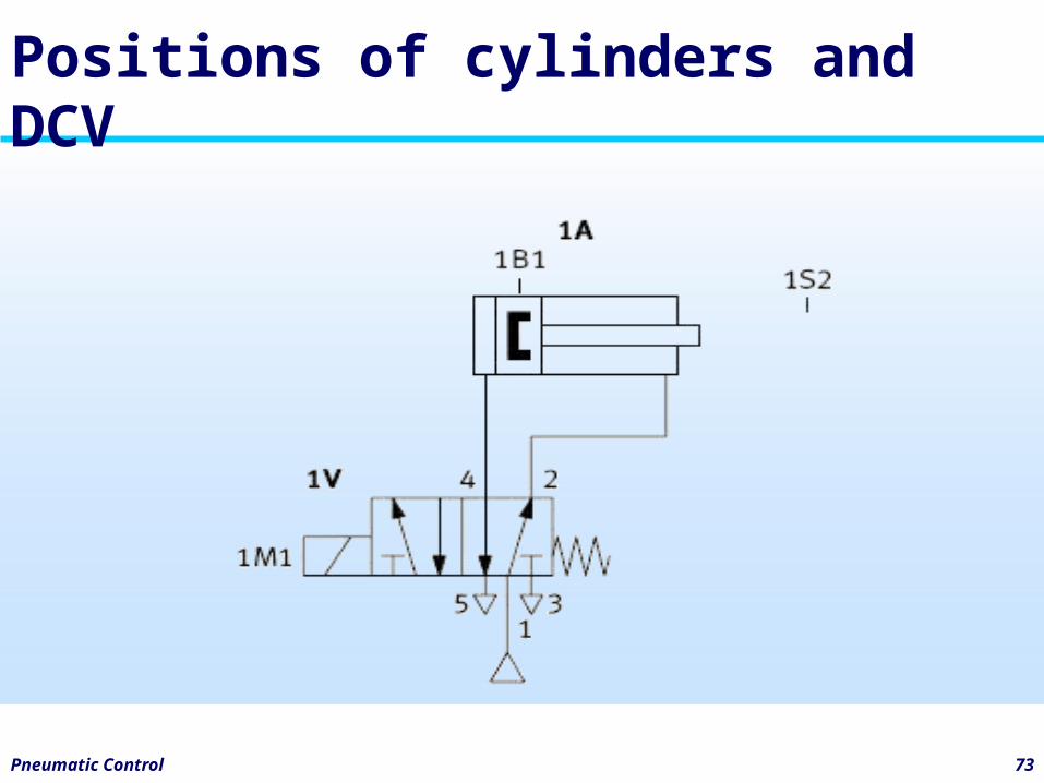
Positions of cylinders and DCV
• All components in a pneumatic circuit diagram are represented
• The cylinder drives are in the initial position.
Pneumatic Control 73
Positions of cylinders and DCV
Pneumatic Control 74
Identification code for components
• Every component (apart from connection lines and connecting tubes) is identified in accordance
• The identification code contains the following information:– Unit number (digit; may be omitted if the
entire circuit consists of one unit)– Circuit number (digit, mandatory)– Component identification (letter, mandatory)– Component number (digit, mandatory)
Pneumatic Control 75
Identification code for components
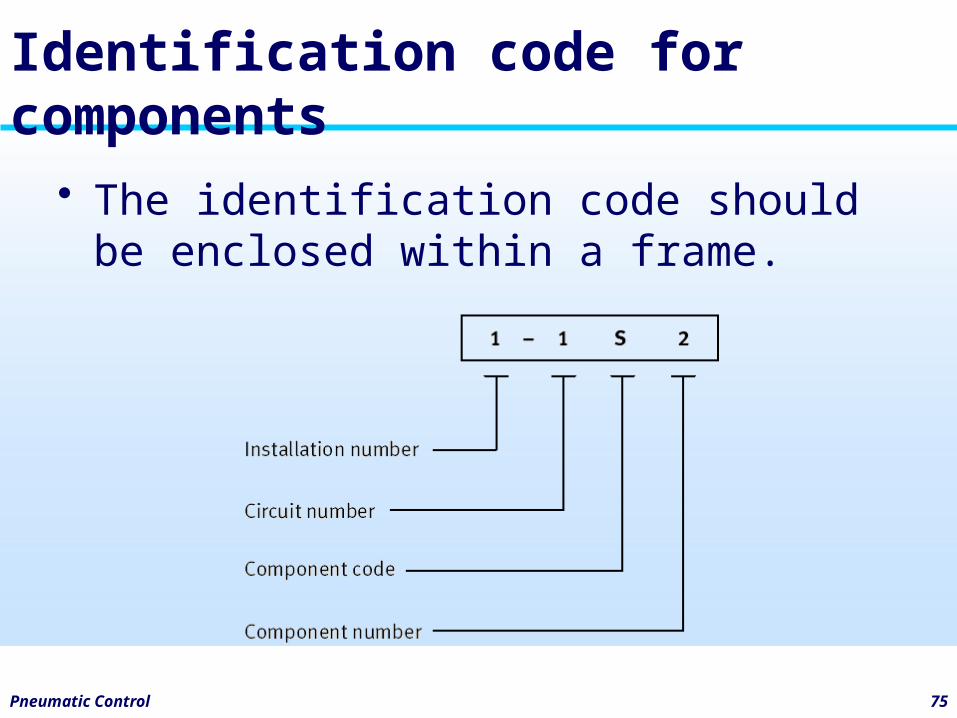
• The identification code should be enclosed within a frame.
Pneumatic Control 76
Unit number
• If there are several units pneumatic control systems in a particular plant, the unit number helps to clarify the assignment between circuit diagrams and control systems.
Pneumatic Control 77
Circuit number
• Preferably all components belonging to the power supply should be identified by circuit number 0. The other circuit numbers are then assigned to the various control chains (= circuits).
Pneumatic Control 78
Component identification and number
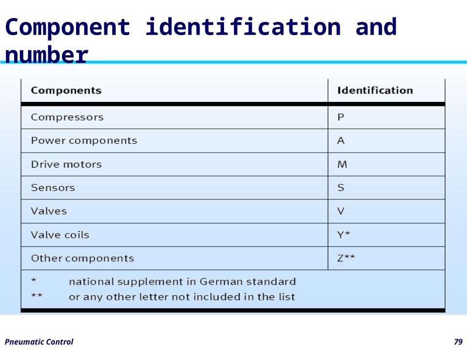
• Every component in a pneumatic control system is assigned a component identification and a component number in the circuit diagram. Within each circuit, components with the same component identification are numbered consecutively from the bottom to the top and from left to right.
Pneumatic Control 79
Component identification and number
Pneumatic Control 80
Technical information
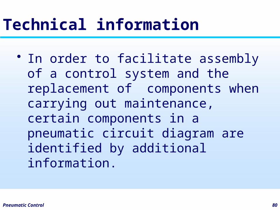
• In order to facilitate assembly of a control system and the replacement of components when carrying out maintenance, certain components in a pneumatic circuit diagram are identified by additional information.
Pneumatic Control 81
Technical information
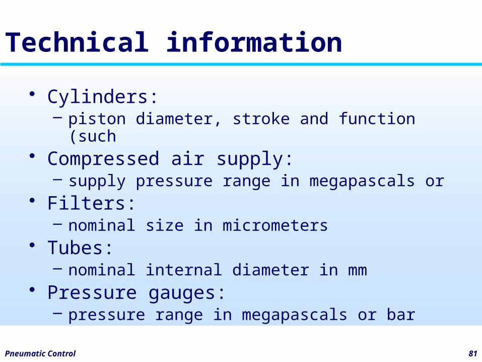
• Cylinders: – piston diameter, stroke and function (such
• Compressed air supply:– supply pressure range in megapascals or
• Filters:– nominal size in micrometers
• Tubes:– nominal internal diameter in mm
• Pressure gauges:– pressure range in megapascals or bar
4aDevelopment of single actuator circuits
Pneumatic Control 83
Control of SAC
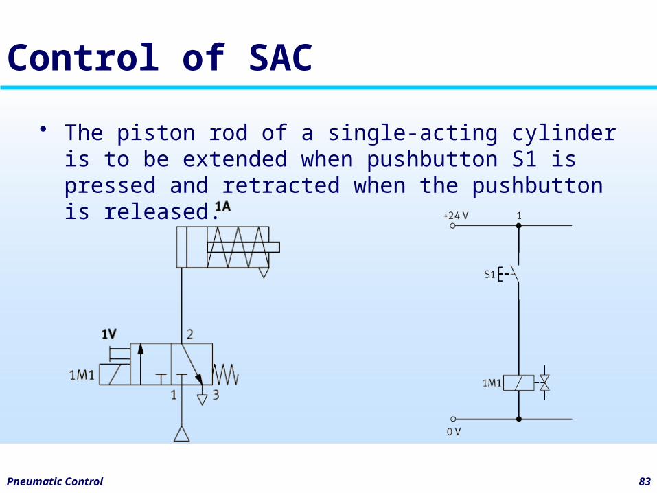
• The piston rod of a single-acting cylinder is to be extended when pushbutton S1 is pressed and retracted when the pushbutton is released.
Pneumatic Control 84
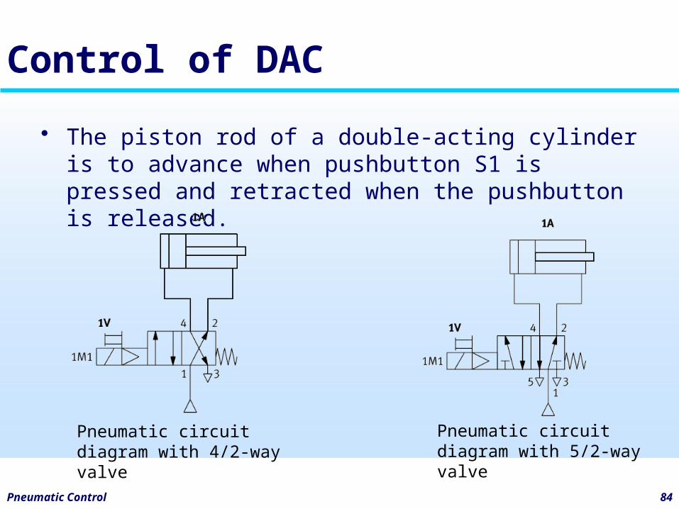
Control of DAC
• The piston rod of a double-acting cylinder is to advance when pushbutton S1 is pressed and retracted when the pushbutton is released.
Pneumatic circuit diagram with 4/2-way valve
Pneumatic circuit diagram with 5/2-way valve
Pneumatic Control 85
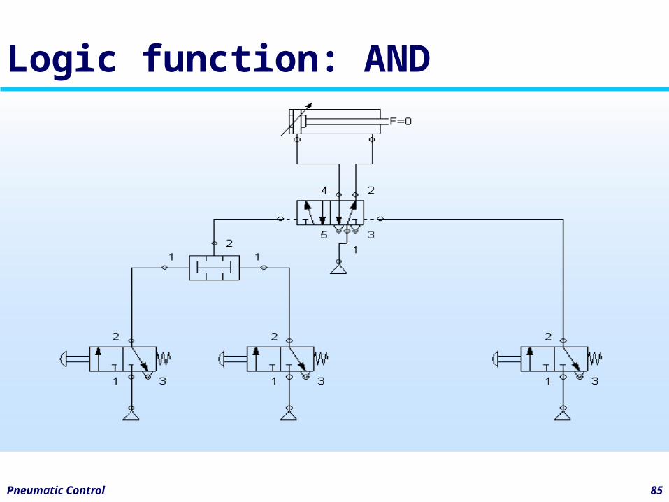
Logic function: AND
Pneumatic Control 86
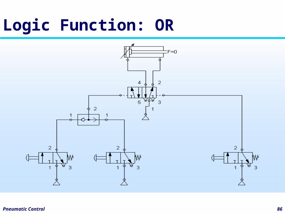
Logic Function: OR
Pneumatic Control 87
Exercise 1
• Control systems with final control valve with spring return
Pneumatic Control 88
Exercise 1a
• Title: Sorting device• Direct actuation of a single-acting
cylinder• Problem: Draw the pneumatic
diagram
Pneumatic Control 89
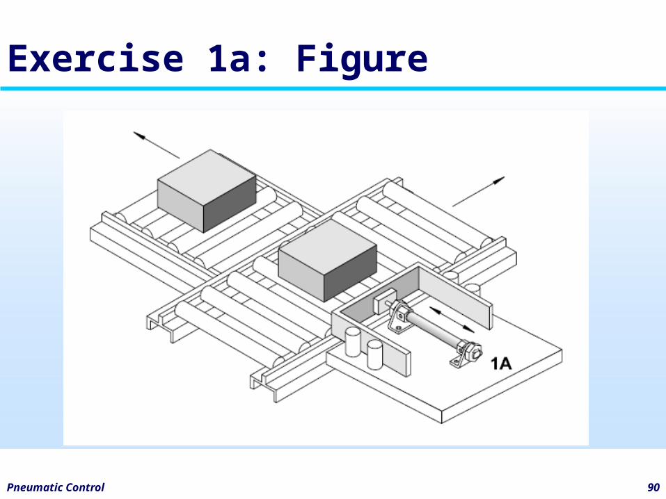
Exercise 1a: Description
• Using a sorting device, parts are to be transferred from a conveyor belt. By pressing the pushbutton switch, the piston rod of a single-acting cylinder pushes the part off the conveyor belt. When the pushbutton is released, the piston rod returns to the retracted end position.
Pneumatic Control 90
Exercise 1a: Figure
Pneumatic Control 91
Exercise 1b
• Title: Opening and closing device• Direct actuation of a double-acting
cylinder• Problem: Draw the pneumatic
diagram
Pneumatic Control 92
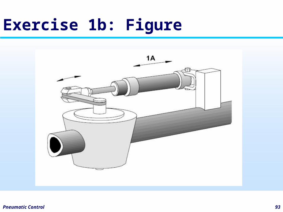
Exercise 1b: Description
• Using a special device, the valve in a pipe line is to be opened and closed.
• The valve is opened by pressing the pushbutton switch. When the pushbutton is released the valve is closed.
Pneumatic Control 93
Exercise 1b: Figure
Pneumatic Control 94
Exercise 1c
• Title: Assembly station• Single-acting cylinder / Double-acting
cylinder• Direct actuation with AND-function of
the input signals• Problem: Draw the pneumatic
diagram
Pneumatic Control 95
Exercise 1c: Description
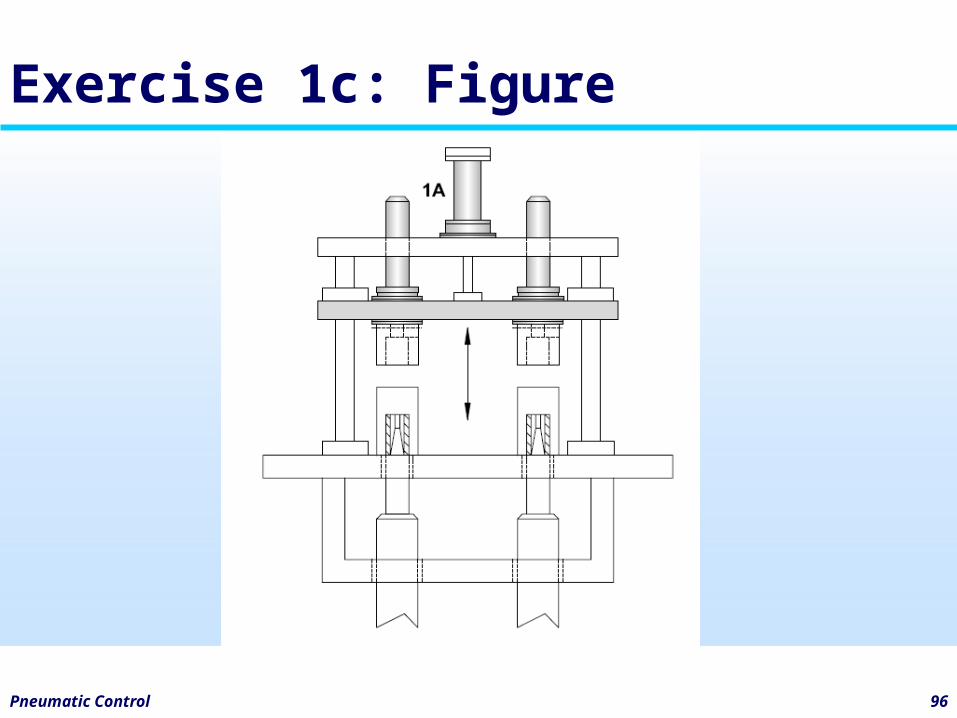
• In an assembly station components are to be put together. By pressing two pushbutton switches the device is advanced and the components are assembled. After releasing the pushbutton switches, the device is returned to its start position.
Pneumatic Control 96
Exercise 1c: Figure
Pneumatic Control 97
Exercise 1d
• Title: Cutting device• Single-acting cylinder / Double-acting
cylinder• Indirect actuation with AND-function
of the input signals• Problem: Draw the pneumatic
diagram
Pneumatic Control 98
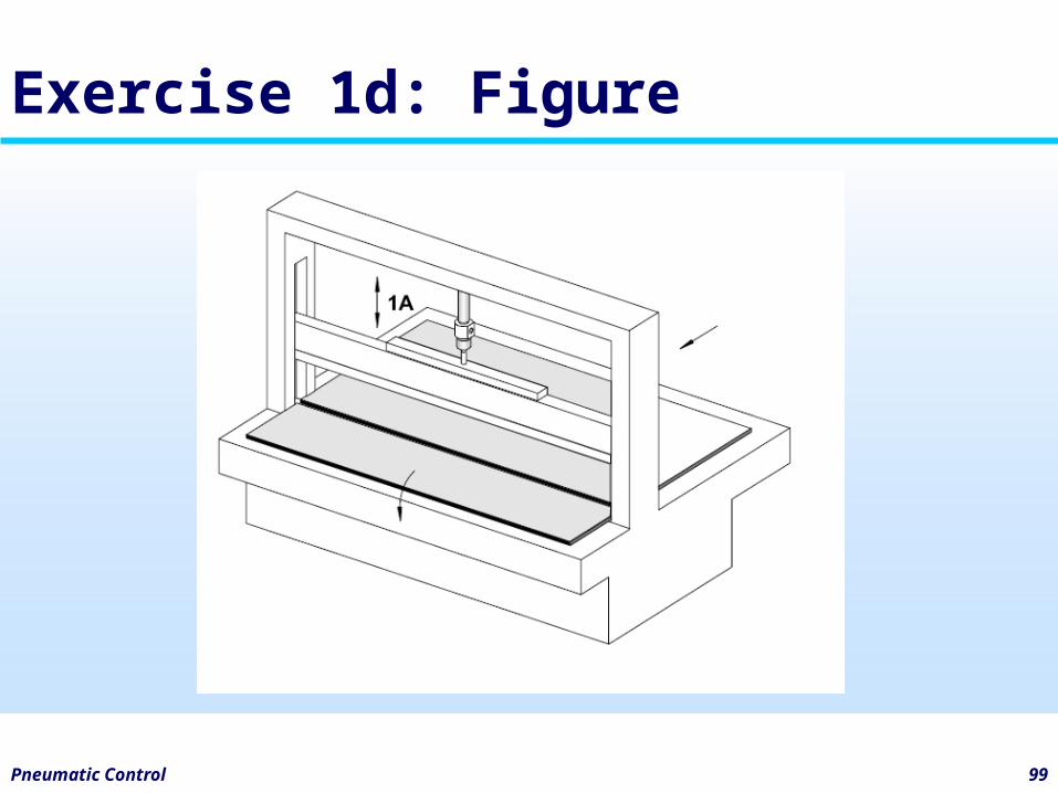
Exercise 1d: Description
• Using a cutting device sheets of paper are to be cut to size.
• By pressing two pushbutton switches the cutting blade is advanced and the sheet of paper is cut. After releasing one pushbutton switch the cutting blade is returned to its start position.
Pneumatic Control 99
Exercise 1d: Figure
Pneumatic Control 100
Exercise 2
• Control systems with double solenoid valve
Pneumatic Control 101
Exercise 2a
• Title: Diverting device• Single-acting cylinder / Double-acting
cylinder• Direct actuation from two different
positions• Problem: Draw the pneumatic
diagram
Pneumatic Control 102
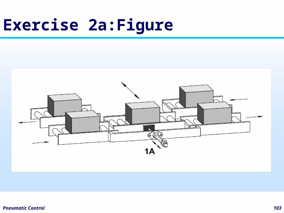
Exercise 2a: Description
• Using a diverting device parts are to be moved from one conveyor track to another conveyor track.
• By pressing a pushbutton switch the frame of the diverting device is pushed forward. The part is moved over and transported onwards in the opposite direction. By pressing another pushbutton switch the frame is returned to its start position.
Pneumatic Control 103
Exercise 2a:Figure
4bDevelopment of multiple actuator circuits
Pneumatic Control 105
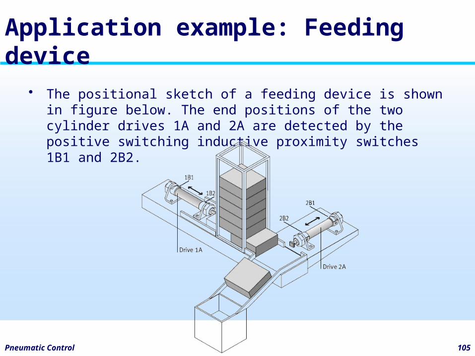
Application example: Feeding device
• The positional sketch of a feeding device is shown in figure below. The end positions of the two cylinder drives 1A and 2A are detected by the positive switching inductive proximity switches 1B1 and 2B2.
Pneumatic Control 106
Displacement-step diagramfor the feeding device
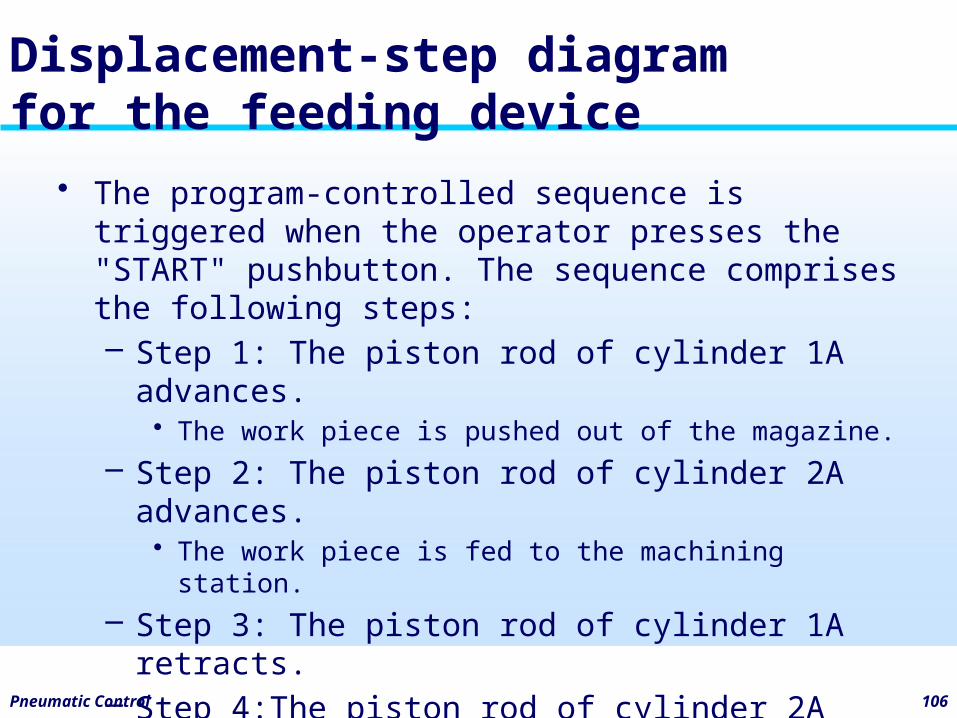
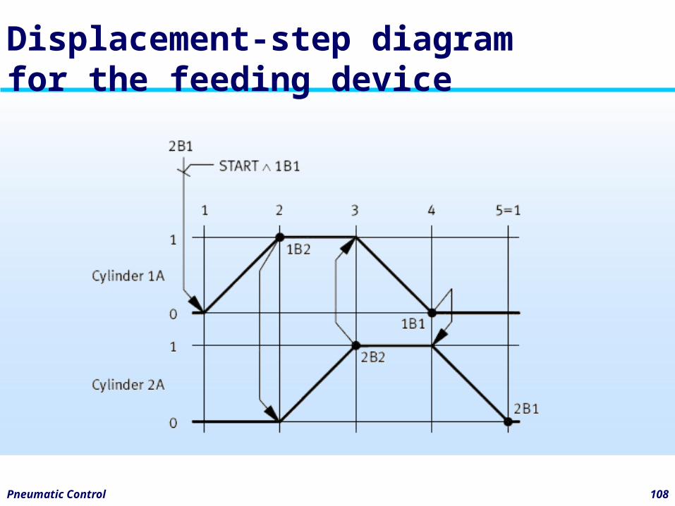
• The program-controlled sequence is triggered when the operator presses the "START" pushbutton. The sequence comprises the following steps:– Step 1: The piston rod of cylinder 1A advances.
• The work piece is pushed out of the magazine.– Step 2: The piston rod of cylinder 2A advances.
• The work piece is fed to the machining station.– Step 3: The piston rod of cylinder 1A retracts.– Step 4:The piston rod of cylinder 2A retracts.
Pneumatic Control 107
Displacement-step diagramfor the feeding device
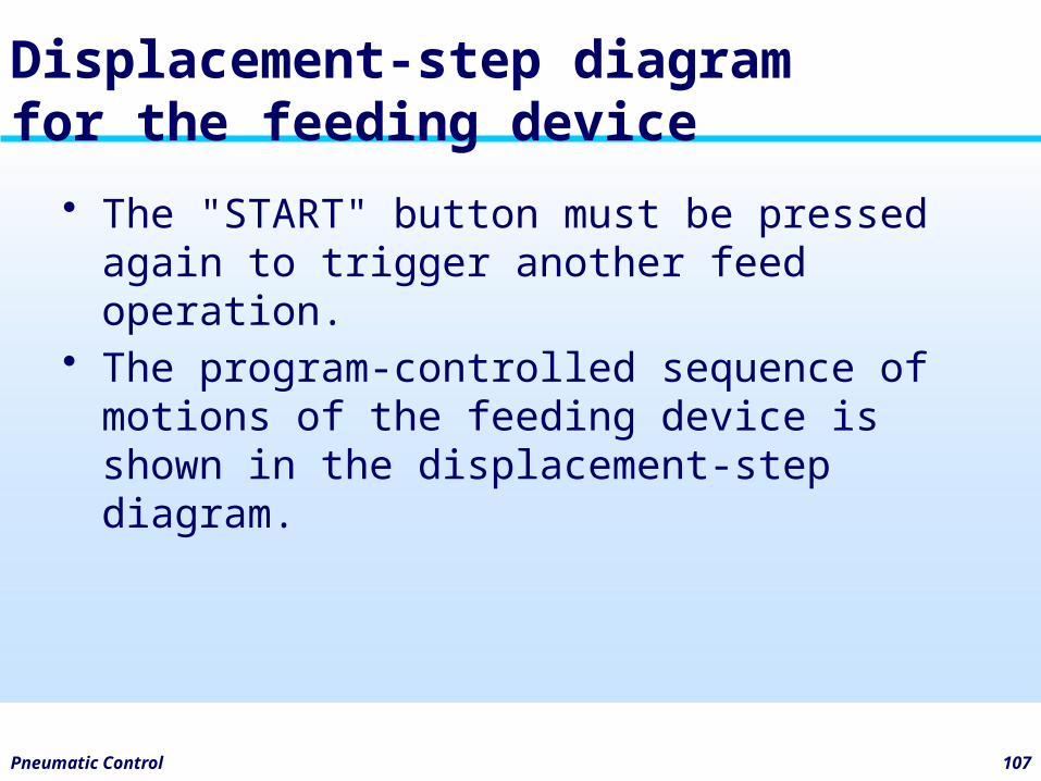
• The "START" button must be pressed again to trigger another feed operation.
• The program-controlled sequence of motions of the feeding device is shown in the displacement-step diagram.
Pneumatic Control 108
Displacement-step diagramfor the feeding device
Pneumatic Control 109
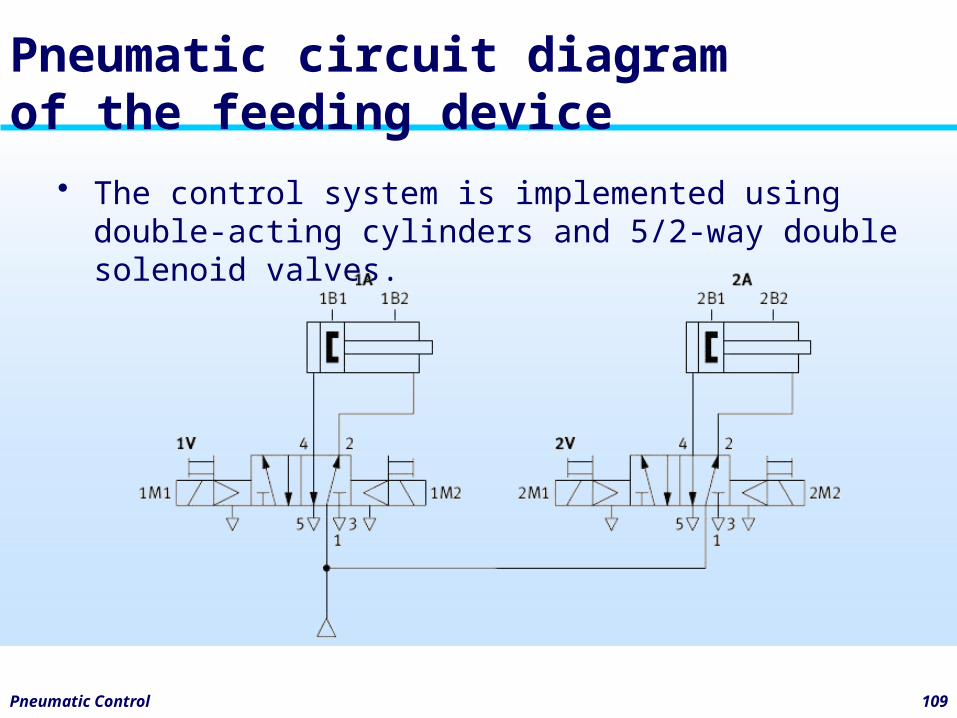
Pneumatic circuit diagramof the feeding device
• The control system is implemented using double-acting cylinders and 5/2-way double solenoid valves.
Pneumatic Control 110
Exercise 3: Multiple actuator
• Title: Bench drill• Draw the pneumatic diagram• Draw the displacement step diagram
Pneumatic Control 111
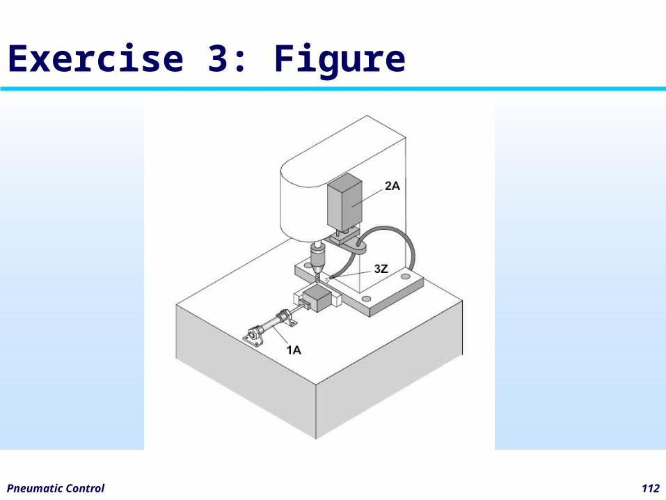
Exercise 3: Description
• Workpieces are inserted into the clamping device by hand. Clamping cylinder 1A is to extend when the start button is pressed. When the workpiece is clamped, it is to be drilled via feed unit 2A and the drill retracted once again. At the same time, the swarf is to be blown away by an air jet 3Z. Then, the clamping cylinder 1A is to release the workpiece.
Pneumatic Control 112
Exercise 3: Figure
Pneumatic Control 113
Exercise 4: Multiple actuator
• Title: Stamping device• Draw the pneumatic diagram• Draw the displacement step diagram
Pneumatic Control 114
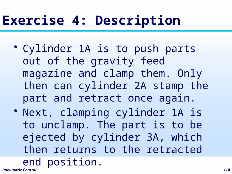
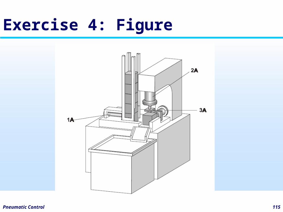
Exercise 4: Description
• Cylinder 1A is to push parts out of the gravity feed magazine and clamp them. Only then can cylinder 2A stamp the part and retract once again.
• Next, clamping cylinder 1A is to unclamp. The part is to be ejected by cylinder 3A, which then returns to the retracted end position.
Pneumatic Control 115
Exercise 4: Figure
5 Design of Pneumatic Circuit with KV Diagram
Pneumatic Control 117
Karnaugh Veitch
• The Karnaugh map, also known as a Veitch diagram (K-map or KV-map for short), is a tool to facilitate management of Boolean algebraic expressions.
• The Karnaugh map was invented in 1952 by Edward W. Veitch and developed further 1953 by Maurice Karnaugh.
Pneumatic Control 118
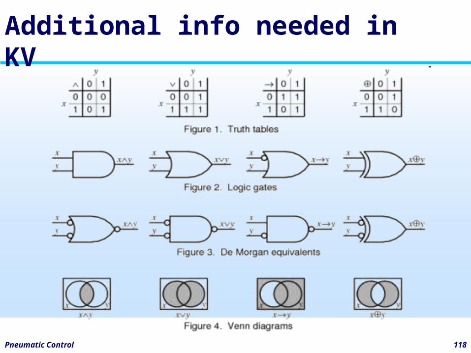
Additional info needed in KV
Pneumatic Control 119
Main purposes of KV Diagram
• To have a memory in pneumatic circuit.
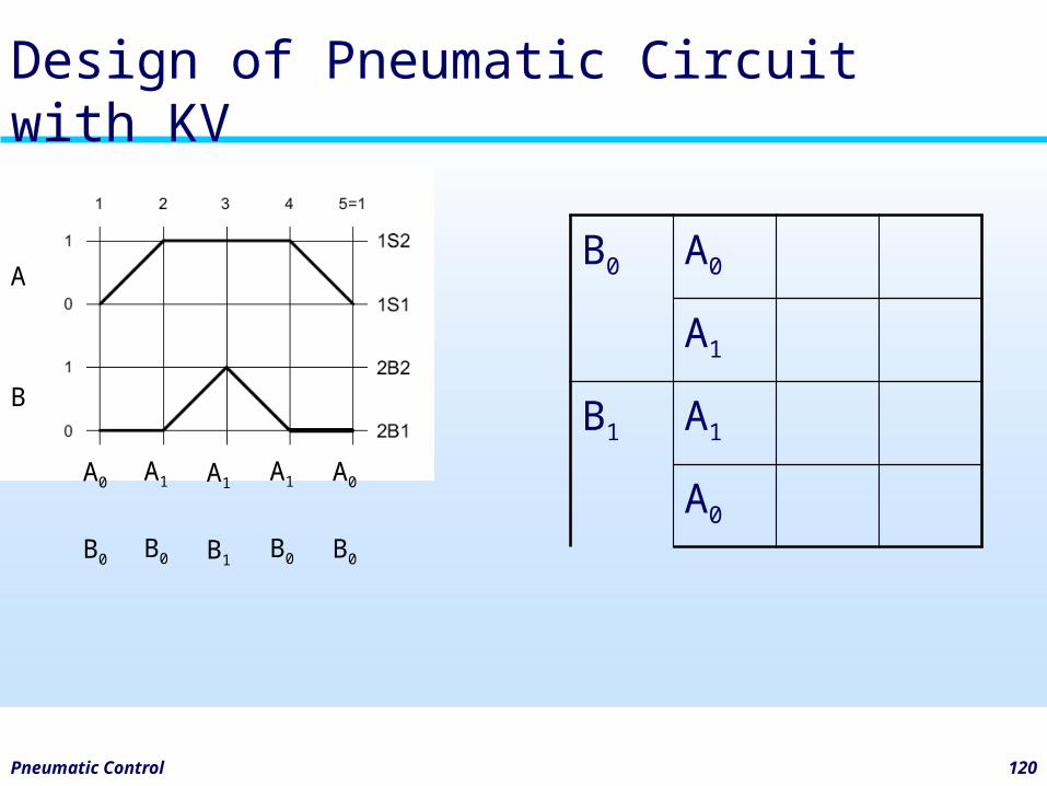
Pneumatic Control 120
Design of Pneumatic Circuit with KV
A
B
A0
B0
A1
B0
A1
B1
A1
B0
A0
B0
B0 A0
A1
B1 A1
A0