Embed Size (px)
Citation preview

Pneumatic Actuators,
Grippers and
Vacuum Components
PROLandscape 11/13/06 9:24 AM Page 2

2
Two Easy Ways to Get Product Information
1. If you know the Festo product type you require
If you know the product type (i.e. DNC) you require
information about, using the CD, simply enter the product
type in the “Search by Product Type” field and click �
2. Search by product feature
Use the logic tree on the left menu of the CD to narrow
your search (i.e. Cylinder, Piston Rod, and Double Acting)
then use the attributes identified on the Product Specification
table (i.e. Piston ø 8mm and heat resistant up to 1500C) to
assist you in selecting products that meet your requirements.
In addition to being located on the CD, all pneumatic linear
actuators, rotary actuators and end effectors Product
Specification table are also printed in the brochure.
Pneumatic
Actuators,
Grippers and
Vacuum
Components
Catalog no.:
13048743
FPO
PROLandscape 11/13/06 9:24 AM Page 3

3
Pneumatic Linear Actuators, Rotary Actuators, Grippers and Vacuum ComponentsContents
Engineering Support
� Cylinder Sizing by Piston Force . . . . . . . . . . . . . . . . . . . . .23
� Buckling Load . . . . . . . . . . . . . . . . . . . . . . . . . . . . . . . . . . .24
� Air Consumption and Quality . . . . . . . . . . . . . . . . . . . . . . .25
Grippers and Vacuum Components
� Grippers . . . . . . . . . . . . . . . . . . . . . . . . . . . . . . . . . . . . . . . .19
�Vacuum Components
� Vacuum Generators . . . . . . . . . . . . . . . . . . . . . . . . . . . . .20
� Suction Cups . . . . . . . . . . . . . . . . . . . . . . . . . . . . . . . . . .20
� Gauges & Accessories . . . . . . . . . . . . . . . . . . . . . . . . . .21
Rotary Actuators
� Rotary and Rotary/Linear Actuators . . . . . . . . . . . . . . . . .17
Linear Actuators � Cylinders
�Cylinders . . . . . . . . . . . . . . . . . . . . . . . . . . . . . . . . . . . . . . . . .4
�Piston Rod Cylinders
� Single Acting . . . . . . . . . . . . . . . . . . . . . . . . . . . . . . . . .5
� Double Acting . . . . . . . . . . . . . . . . . . . . . . . . . . . . . . . .6
�Rodless Cylinders
� Double Acting . . . . . . . . . . . . . . . . . . . . . . . . . . . . . . . .8
� Bellows and Bladder . . . . . . . . . . . . . . . . . . . . . . . . . . .8
� Environmental and Specialty Cylinders . . . . . . . . . . . . . .9
Linear Actuators �Guided Cylinders
�Guided Cylinders . . . . . . . . . . . . . . . . . . . . . . . . . . . . . . . . .10
�Piston Rod Cylinders
� Single Acting . . . . . . . . . . . . . . . . . . . . . . . . . . . . . . . .11
� Double Acting . . . . . . . . . . . . . . . . . . . . . . . . . . . . . . .12
�Rodless Cylinders
� Double Acting . . . . . . . . . . . . . . . . . . . . . . . . . . . . . . .14
� Specialty Cylinders . . . . . . . . . . . . . . . . . . . . . . . . . . . . .15 References
� CD Search Functions . . . . . . . . . . . . . . . . . . . . . . . . . . . . . . .2
� Table of Contents . . . . . . . . . . . . . . . . . . . . . . . . . . . . . . . . . .3
� Product Type Index . . . . . . . . . . . . . . . . . . . . . . . . . . . . . . .26
� Product Range Overview . . . . . . . . . . . . . . . . . . . . . . . . . . .27
PROLandscape 11/13/06 9:24 AM Page 4

Cylinders
�Piston Rod Cylinders
�Single Acting . . . . . . . . . . . . . . . .5
�Double Acting . . . . . . . . . . . . . . .6
�Rodless Cylinders
�Double Acting . . . . . . . . . . . . . . .8
�Bellows and Bladder . . . . . . . . .8
�Environmental and
Specialty Cylinders . . . . . . . . . . . . .9
PROLandscape 11/13/06 9:24 AM Page 5

5
�
�
� �
��
�
�
�
� ��
��
Type Dimensions Piston ø Stroke
P A
�
�
Product Specifications
General
Compact
Fixe
d C
ush
ioni
ng
EG Metric [mm] 2.5 to 6 5 to 25
ESNU Metric [mm] 8 to 63 1 to 50
ESNU Inch Inch [in] 5/16 to 2 1/2 0.04 to 2
AEVU Metric [mm] 12 to 100 1 to 25
AEVU Inch Inch [in] 1/2 to 4 0.05 to 1
EGZ Metric [mm] 6 to 16 5 to 15
AEVC Metric [mm] 4 to 100 2.5 to 25
AEN Metric [mm] 12 to 125 1 to 500
Mag
net
for
Posi
tion
ing
Sen
sing
EMM Metric [mm] 10 to 32 5 to 15
� Piston Rod Cylinders � Single Acting
�
�
�
�
�
�� ��
�� ��
�� ��
����
� �
�
�
�� �� ��
�� �� �� �� ��
�
��
��
�� ��
��
������������
Rod Thread/Connection
K3 K2 K5 K6 K8 MA
Mal
e Ro
d T
hre
ad
Wit
hou
tTh
read
Fem
ale
Rod
Th
read
Exte
nded
Mal
e
Thre
ad
Sp
ecia
l Th
read
Sh
orte
ned
Mal
e
Thre
ad
Exte
nded
Pis
ton
Rod
Axi
al A
irCo
nnec
tion
Lead Time 1
Sam
e/N
ext
Day
≤O
ne W
eek
>O
ne W
eek
��
��
��
�� �� ��
��
Function/Performance
S2 S206 Z
Func
tion
/Per
form
ace
Thro
ugh
, Hol
low
Pist
on R
od, H
eat
Resi
stan
tup
to
15
00C
/30
20F
Pulli
ng V
ersi
on
��
��
��
��
��
�� ��
��
��
Special Environment
S6 S20 S26 CT K10
Hea
tRe
sist
ant
up t
o 1
50
0C
Thro
ugh
, Hol
low
Pist
on R
od
Thro
ugh
, Hol
low
Pist
on R
od, H
eat
Resi
stan
tup
to
15
00C
/30
20F
Free
ofC
opp
er,
PTFE
and
Sili
cone
Sm
ooth
Ano
dis
ed
Pist
on R
od
1) The lead times shown are typical times from order placement until the item will ship, and are approximate only. The actual shipping date will be confirmed upon order placement. Products with more than one lead-time listed reflect variations for options ordered.
Standard Available� ��
Cylinders
Lin
ea
r Actu
ato
rs �C
ylin
de
rs
PROLandscape 11/13/06 9:24 AM Page 6

6
�� �� ��
�� �� ��
�� �� ��
�� �� ��
�
�
�
�
��� ��
Type Dimensions Piston ø Stroke
P PPV A
�
�
�
�
�
�
�
�
�
��
�
�
�
�
�
�
�
��
�
� �
� �
� �
��
��
��
��
��
��
��
��
��
��
��
��
�� �� �� �� ��
��
�� �� �� �� ��
��
����
��
�� ��
�
�
�
�
�
�
�
�
�
�
�
�
�� �� �� �� �� �� �� �� �� �� ��
�� �� �� �� ��
���� ��
��
����
���� ��
�
�
�
�
�
�
�
�
�
�
�
�
�
�
�
�
�
� �
�
�
�
�
� � � � ���
���
�
�
�
�
�
�
�
�
�
�
��
�� ��
�� ��
��
��
��
��
����
�� ��
��
�� ��
��
�� �� �� ��
�� ��
��
��
��
��
��
��
�� �� ����
����
��
��
��
��
��
�� ��
�� �� �� �� �� ��
�� �� �� �� ��
��
S1 S2 S20 S10 S11 KP EL H,T M,PK2 K6 K3 K5 K8 K7 MA S3 R3,S8 S6 S26 S206 R8 K10 CT
Rod Thread/Air Connection
Mal
e Ro
d T
hre
ad
T
T P
H M
Exte
nd
ed M
ale
Th
rea
d
Sh
orte
ned
Mal
eTh
read
Pis
ton
Rod
Fem
ale
Rod
Th
read
Sp
ecia
l Th
read
Wit
hou
tTh
read
Exte
nded
Pis
ton
Rod
Sp
ecia
l Sp
anne
rFl
ats
Axi
al A
irCo
nnec
tion
Function/Performance Special Environment
Rein
forc
emed
Pi
ston
Rod
Thro
ugh
Pis
ton
Rod
Thro
ugh
, Hol
low
Pist
on R
od
Slo
w S
pee
d
(Con
stan
tM
otio
n)
Low
Fri
ctio
n
Clam
pin
g U
nit
End
-pos
itio
n Lo
ck
Tand
em/h
igh
-for
ceCy
lind
er
Mul
ti-p
osit
ion
Cylin
der
Lead Time 1
Sam
e/N
ext
Day
≤O
ne W
eek
>O
ne W
eek
Sta
inle
ssS
teel
, Cor
rosi
onan
d A
cid
Res
ista
nt
Sta
inle
ssS
teel
, U
SD
AH
1 A
pp
rove
d
Sta
inle
ssS
teel
Pi
ston
Rod
Incr
ease
d C
orro
sion
Prot
ecti
on
Hea
tRe
sist
ant
up t
o 1
50
0C
/30
20F
Thro
ugh
Pis
ton
Rod
, Hea
tRe
sist
ant
up t
o 1
50
0C
Thro
ugh,
Hol
low
Pis
ton
Rod,
Hea
tRes
ista
ntup
to 1
500 C
Wip
erS
eal
Sm
ooth
Ano
diz
ed
Pist
on R
od
Free
ofC
opp
er,
PTFE
and
Sili
cone
Product Specifications
General
Compact
Stainless Steel
Fixe
d C
ush
ioni
ng
DSNU Metric [mm] 8 to 63 1 to 500
DSNU Inch Inch [in] 5/16 to 2 1/2 0.04 to 19.6
DNA Inch Inch [in] 1 1/2 to 5 1/2 to 80
ADVC Metric [mm] 4 to 100 2.5 to 25
DMM Metric [mm] 10 to 32 5 to 50
DNC Metric [mm] 32 to 125 10 to 2,000
DNC Inch Inch [in] 1 1/4 to 5 0.4 to 80
DNG Metric [mm] 32 to 320 10 to 2,000
DNG Inch Inch [in] 1 1/4 to 6 0.4 to 78.7
ADN Metric [mm] 12 to 125 1 to 500
ADVU Metric [mm] 12 to 125 1 to 400
ADVU Inch Inch [in] 1/2 to 5 0.04 to 16
CRDSNU Metric [mm] 12 to 25 10 to 500
CRDSNU Inch Inch [in] 1/2 to 1 0.4 to 19.7
CRDSW Metric [mm] 32 to 63 1 to 500
CRDSW Inch Inch [in] 1 1/4 to 2 1/2 0.04 to 20
CRDNG Metric [mm] 32 to 125 10 to 2,000
CRDNG Inch Inch [in] 1 1/4 to 5 0.4 to 78
CRDG Metric [mm] 12 to 63 1 to 500
CRHD Metric [mm] 32 to 100 10 to 500
Ad
just
able
Cus
hio
ning
Mag
net
for
Posi
tion
ing
Sen
sing
� Piston Rod Cylinders � Double Acting
Lin
ea
r Actu
ato
rs �C
ylin
de
rs
PROLandscape 11/13/06 9:24 AM Page 7

7
�
��
��
�� �� �� �� ��
�
�
�
�
��
�� ��
��
S1 S2 S20 S10 S11 KP EL H,T M,PK2 K6 K3 K5 K8 K7 MA S3 R3,S8 S6 S26 S206 R8 K10 CT
Rod Thread/Air Connection
Mal
e Ro
d T
hre
ad
Exte
nd
ed M
ale
Th
rea
d
Sh
orte
ned
Mal
eTh
read
Pis
ton
Rod
Fem
ale
Rod
Th
read
Sp
ecia
l Th
read
Wit
hou
tTh
read
Exte
nded
Pis
ton
Rod
Sp
ecia
l Sp
anne
rFl
ats
Axi
al A
irCo
nnec
tion
Function/Performance Special Environment
Rein
forc
emed
Pi
ston
Rod
Thro
ugh
Pis
ton
Rod
Thro
ugh
, Hol
low
Pist
on R
od
Slo
w S
pee
d
(Con
stan
tM
otio
n)
Low
Fri
ctio
n
Clam
pin
g U
nit
End
-pos
itio
n Lo
ck
Tand
em/h
igh
-for
ceCy
lind
er
Mul
ti-p
osit
ion
Cylin
der
Lead Time 1
Sam
e/N
ext
Day
≤O
ne W
eek
>O
ne W
eek
Sta
inle
ssS
teel
, Cor
rosi
onan
d A
cid
Res
ista
nt
Sta
inle
ssS
teel
, U
SD
AH
1 A
pp
rove
d
Sta
inle
ssS
teel
Pi
ston
Rod
Incr
ease
d C
orro
sion
Prot
ecti
on
Hea
tRe
sist
ant
up t
o 1
50
0C
/30
20F
Thro
ugh
Pis
ton
Rod
, Hea
tRe
sist
ant
up t
o 1
50
0C
Thro
ugh,
Hol
low
Pis
ton
Rod,
Hea
tRes
ista
ntup
to 1
500 C
Wip
erS
eal
Sm
ooth
Ano
diz
ed
Pist
on R
od
Free
ofC
opp
er,
PTFE
and
Sili
cone
Product Specifications
Type Dimensions Piston ø Stroke
P PPV A
Fixe
d C
ush
ioni
ng
Ad
just
able
Cus
hio
ning
Mag
net
for
Posi
tion
ing
Sen
sing
CDN Metric [mm] 32 to 100 10 to 2,000
DLP Metric [mm] 80 to 320 40 to 2,000
STA Metric [mm] 20 to 80 15 to 40
Clean Design
Process Valve Actuator
Stopper Cylinder
1) The lead times shown are typical times from order placement until the item will ship, and are approximate only. The actual shipping date will be confirmed upon order placement. Products with more than one lead-time listed reflect variations for options ordered.
Standard Available� ��
Cylinders
Lin
ea
r Actu
ato
rs �C
ylin
de
rs
PROLandscape 11/13/06 9:24 AM Page 8

8
1) The lead times shown are typical times from order placement until the item will ship, and are approximate only. The actual shipping date will be confirmed upon order placement. Products with more than one lead-time listed reflect variations for options ordered.
Standard Available� ��
Sam
e/N
ext
Day
≤O
ne W
eek
>O
ne W
eek
�
�
� � �
���
Product Specifications
Type Dimensions Piston ø Stroke
P PPV A
Fixe
d C
ush
ioni
ng
DGO Metric [mm] 12 to 40 10 to 4,000
DGO Inch Inch [in] 1/2 to 1 5/8 0.5 to 157
Ad
just
able
Cus
hio
ning
Mag
net
for
Posi
tion
ing
� Rodless Cylinders � Double Acting
1/2
1/2
Lead Time 1
�
����
��
�� ��
��
� Rodless Cylinders � Bellows and Bladders
Product Specifications
Type Dimensions Piston ø Stroke
EB Metric [mm] 145 to 385 60 to 230
EBS Metric [mm] 80 to 100 105 to 110
EV Metric [mm] 12 to 63 3 to 5
MAS Metric [mm] 10 to 40 Length 40 to 9,000
Lead Time 1
Sam
e/N
ext
Day
≤O
ne W
eek
>O
ne W
eek
Cylinders
Linear
Actu
ators�
Cylind
ers
PROLandscape 11/13/06 9:24 AM Page 9

�
�
�
�
�
�
�
�
Type Dimensions Piston ø Stroke
P PPV A
9
� �
� �
� �
� �
� �
� �
�
� �
�
�
� �
��
��
� � ��
� �
�
�
�
�
�
�
� � �
�
�
�
�
��
�� ���
�� �� �� �� ��
��
��
��
��
CRDNG Metric [mm] 32 to 125 10 to 2,000
CRDNG Inch Inch [in] 1 1/4 to 5 0.4 to 78
�
��
�
�
�
�
�
�
�
�
Product Specifications
Stainless Steel
Clean Design
Fixe
d C
ush
ioni
ng
CRDG Metric [mm] 12 to 63 1 to 500
CRDSNU Metric [mm] 12 to 25 1 to 500
CRDSNU Inch Inch [in] 1/2 to 1 0.4 to 19.7
CRDSW Metric [mm] 32 to 63 1 to 500
CRDSW Inch Inch [in] 1 1/4 to 2 1/2 0.04 to 20
CDN Metric [mm] 32 to 100 10 to 2,000
CRHD Metric [mm] 32 to 100 10 to 500
Ad
just
able
Cus
hio
ning
Mag
net
for
Posi
tion
ing
Sen
sing
Process Valve Actuator
DLP Metric [mm] 80 to 320 10 to 2,000
Stopper Cylinder
STA Metric [mm] 20 to 80 15 to 40
� Environmental and Specialty Cylinders
Rod Thread/Connection
K2 K3 K8
Mal
e Ro
d T
hre
ad
Exte
nd
ed M
ale
Th
rea
d
Fem
ale
Rod
Th
read
Wit
hou
tTh
read
Exte
nded
Pis
ton
Rod
Function
S2
Thro
ugh
Pis
ton
Rod
Special Environment
S3 R3,S8 S6
Sta
inle
ssS
teel
Cor
rosi
on
and
Aci
d R
esis
tant
Sta
inle
ssS
teel
,
US
DA
H1
Ap
pro
ved
Sta
inle
ssS
teel
Pist
on R
od
Incr
ease
d C
orro
sion
Prot
ecti
on
Hea
tRe
sist
ant
up t
o
15
00C
/30
20F
Lead Time 1
Sam
e/N
ext
Day
≤O
ne W
eek
>O
ne W
eek
1) The lead times shown are typical times from order placement until the item will ship, and are approximate only. The actual shipping date will be confirmed upon order placement. Products with more than one lead-time listed reflect variations for options ordered.
Standard Available� ��
Lin
ea
r Actu
ato
rs �C
ylin
de
rs
PROLandscape 11/13/06 9:24 AM Page 10

Guided Cylinders
�Piston Rod Cylinders
�Single Acting . . . . . . . . . .11
�Double Acting . . . . . . . . .12
�Rodless Cylinders . . . . . . . .14
�Specialty Cylinders . . . . . . .15
PROLandscape 11/13/06 9:24 AM Page 11

� �
�
11
�
�
�
��
�
�
��
��
��
��
��
�� �� �� �� �� �� ��
�
�� ���
��
�
��
��
�� �� �� ��
�
�
�
�
Product Specifications
Type Dimensions Piston ø Stroke
P A
Fixe
d C
ush
ioni
ng
EMML Metric [mm] 10 to 32 5 to 15
EZH Metric [mm] 3.6 to 22 10 to 50
AEVULQ Metric [mm] 12 to 100 1 to 25
AEVULQ Inch Inch [in] 5/8 to 4 0.04 to 1
AEN-Q Metric [mm] 12 to 125 1 to 500
Mag
net
for
Posi
tion
ing
Sen
sing
� Guided Piston Rod Cylinders � Single Acting
Rod Thread/Connection
K3 K2 K5 K8
Mal
e Ro
d T
hre
ad
Wit
hou
tTh
read
Fem
ale
Rod
Th
read
Exte
nd
ed M
ale
Th
rea
d
Exte
nd
edPi
ston
Rod
Sp
ecia
l Th
rea
d
Special Environment
S6 S26 S206 K10
Hea
tRe
sist
ant
up t
o 1
50
0C
Thro
ugh
Pist
on R
od, H
eat
Resi
stan
tup
to 1
50
0C
Thro
ugh
Hol
low
Pis
ton
Rod
Hea
tRes
ista
ntup
to 1
500 C
Sm
ooth
Ano
diz
ed
Pist
on R
od
Lead Time 1
Sam
e/N
ext
Day
≤O
ne W
eek
>O
ne W
eek
Function/Performance
S2 S20 Z
Thro
ugh
Pis
ton
Rod
Thro
ugh
, Hol
low
Pist
on R
od
Pulli
ng V
ersi
on
1) The lead times shown are typical times from order placement until the item will ship, and are approximate only. The actual shipping date will be confirmed upon order placement. Products with more than one lead-time listed reflect variations for options ordered.
Standard Available� ��
Guided Cylinders
Lin
ea
r Actu
ato
rs �G
uid
ed
Cy
lind
ers
Square Rod
Bearing Guided Piston
Oval Piston
PROLandscape 11/13/06 9:24 AM Page 12

12
��
�
�
�
�
�
��
�� ��
�
�
�
�
�
�
�
�
�
�
�
�� �� ��
�� �� ��
�
�
�
�
�
� �
Type Dimensions Piston ø Stroke
P PPV A
Product Specifications
Square Rod
Oval Piston
Bearing Guided PistonFi
xed
Cus
hio
ning
ADN-Q Metric [mm] 12 to 125 1 to 500
ADVULQ Metric [mm] 12 to 125 1 to 400
ADVULQ Inch Inch [in] 1/2 to 5 0.05 to 16
DNGL Metric [mm] 32 to 320 10 to 2,000
DNGL Inch Inch [in] 1 1/4 to 4 0.04 to 24
DZF Metric [mm] 12 to 63 1 to 1,000
DZF Inch Inch [in] 1/2 to 2 1/2 3/8 to 12
DZH Metric [mm] 16 to 63 1 to 1,000
DZH Inch Inch [in] 5/8 to 2 1/2 0.04 to 40
DNC-Q Metric [mm] 32 to 125 10 to 2,000
DSNU-Q Metric [mm] 8 to 63 1 to 500
DFP Metric [mm] 10 to 80 25 to 500
DPZ Metric [mm] 10 to 32 10 to 100
DPZC Metric [mm] 6 to 16 10 to 100
HMP Metric [mm] 16 to 32 50 to 400
Ad
just
able
Cus
hio
ning
Sh
ock
Ab
sorb
er,
Inte
rnal
Mou
ntin
g
Mag
net
for
Posi
tion
ing
Sen
sing
� Guided Piston Rod Cylinders � Double Acting
��
��
��
��
�
�
�
�
�
�
�
�� ��
�
�
�
�
�
�
�
��
�� ��
��
��
��
��
��
��
��
��
��
��
��
����
��
��
��
��
��
��
��
��
�� �� �� ��
�� ����
��
�
�
�
�� ��
�� ��
��
�� ��
�� ��
�� ��
�� ��
����
�� ��
�� �� ��
�� �� ��
�� �� �� �� ��
K3 K2 K5 K8 KP S2 S20 GF KF EL S6 CT R3 R8 S26 S206
Rod Thread/Connection
Mal
e Ro
d T
hre
ad
Fem
ale
Rod
Th
read
Wit
hou
tTh
read
Exte
nd
ed M
ale
Thre
ad
Sp
ecia
l Th
read
Exte
nded
Pis
ton
Rod
Wit
h A
dju
stab
le
Trun
nion
Mou
ntin
g
Function/Performance
Clam
pin
g U
nit
Thro
ugh
Pis
ton
Rod
Thro
ugh
, Hol
low
Pist
on R
od
Plai
n B
eari
ng G
uid
e
Reci
rcul
atin
g B
all
Bea
ring
Gui
de
End
-pos
itio
n Lo
ck
Special Environment
Hea
tre
sist
ant
up t
o 1
50
0C
Free
ofC
opp
er, P
TFE,
and
Sili
cone
Incr
ease
d C
orro
sion
Prot
ecti
on
Wip
erS
eal
Thro
ugh
Pis
ton
Rod
, Hea
t
Resi
stan
tup
to
15
00C
Thro
ugh
Hol
low
Pis
ton
Rod,
Hea
tRes
ista
ntup
to 1
50
0C
Lead Time 1
Sam
e/N
ext
Day
≤O
ne W
eek
>O
ne W
eek
Lin
ea
r Actu
ato
rs �G
uid
ed
Cy
lind
ers
PROLandscape 11/13/06 9:24 AM Page 13

13
�
�
�
�
�
�
�
�
��
�� ��
��
�
��
�� ��
��
�� ��
�� ��
�� ��
�
�
�
�
��
��
��
��
��
�
�
�
� �
��
�
�
�
�
�
�
�
�
�
�
�
�� �� ��
��
��
Type Dimensions Piston ø Stroke
P PPV A
Product Specifications
Integrated Linear Guide
Fixe
d C
ush
ioni
ng
Ad
just
able
Cus
hio
ning
Sh
ock
Ab
sorb
er,
Inte
rnal
Mou
ntin
g
Mag
net
for
Posi
tion
ing
Sen
sing
K3 K2 K5 K8 KP S2 S20 GF KF EL S6 CT R3 R8 S26 S206
Rod Thread/Connection
Mal
e Ro
d T
hre
ad
Fem
ale
Rod
Th
read
Wit
hou
tTh
read
Exte
nd
ed M
ale
Th
rea
d
Sp
ecia
l Th
read
Exte
nded
Pis
ton
Rod
Wit
h A
dju
stab
le
Trun
nion
Mou
ntin
g
Function/Performance
Clam
pin
g U
nit
Thro
ugh
Pis
ton
Rod
Thro
ugh
, Hol
low
Pist
on R
od
Plai
n B
eari
ng G
uid
e
Reci
rcul
atin
g B
all
Bea
ring
Gui
de
End
-pos
itio
n Lo
ck
Special Environment
Hea
tre
sist
ant
up t
o 1
50
0C
Free
ofC
opp
er, P
TFE,
and
Sili
cone
Incr
ease
d C
orro
sion
Prot
ecti
on
Wip
erS
eal
Thro
ugh
Pis
ton
Rod
, Hea
t
Resi
stan
tup
to
15
00C
Thro
ugh
Hol
low
Pis
ton
Rod,
Hea
tRes
ista
ntup
to 1
50
0C
Lead Time 1
Sam
e/N
ext
Day
≤O
ne W
eek
>O
ne W
eek
DFC Metric [mm] 4 to 10 5 to 30
DFM Metric [mm] 12 to 100 10 to 200
DFM-B Metric [mm] 12 to 100 10 to 400
ADVUL Metric [mm] 12 to 100 1 to 400
DMML Metric [mm] 10 to 32 5 to 50
HMPL Metric [mm] 12 to 20 30 to 200
SLE Metric [mm] 10 to 50 10 to 500
SLF Metric [mm] 6 to 16 10 to 80
SLS Metric [mm] 6 to 16 5 to 30
SLT Metric [mm] 6 to 25 10 to 200
1) The lead times shown are typical times from order placement until the item will ship, and are approximate only. The actual shipping date will be confirmed upon order placement. Products with more than one lead-time listed reflect variations for options ordered.
Standard Available� ��
Guided Cylinders
Lin
ea
r Actu
ato
rs �G
uid
ed
Cy
lind
ers
PROLandscape 11/13/06 9:24 AM Page 14

14
DGC Metric [mm] 8 to 40 1 to 5,000
SPZ Metric [mm] 10 to 32 10 to 100
SLM Metric [mm] 12 to 40 10 to 1,500
SLG Metric [mm] 8 to 18 100 to 900
DGP Metric [mm] 18 to 80 10 to 3,000
DGP Inch Inch [in] 11/16 to 3 0.4 to 118
DGPL Metric [mm] 18 to 80 10 to 3,000
DGPL Inch Inch [in] 11/16 to 3 0.4 to 118
�� �� �
�� �� �� �
� �
���
��
�
� �
�� �� ��
�
�
�
�
�
�
�
�
�
��
����
��
�
��
��
��
�
����
� �
��
�
Product Specifications
Type Dimensions Piston ø Stroke
P PPV A
Fixe
d C
ush
ioni
ng
Ad
just
able
Cus
hio
ning
Sh
ock
Ab
sorb
er,
Inte
rnal
Mou
ntin
g
Mag
net
for
Posi
tion
ing
Sen
sing
� Guided Rodless Cylinders � Double Acting
Function/Performance
KP GF KF FA
Clam
pin
g U
nit
Plan
Bea
ring
Gui
de
Reci
rcul
atin
g B
all
Bea
ring
Gui
de
Pass
ive
Gui
de
Axi
s
Lead Time 1
Sam
e/N
ext
Day
≤O
ne W
eek
>O
ne W
eek
Special Environment
S6 CT
Hea
tRe
sist
ant
up t
o 1
50
0C
Free
ofC
opp
er, P
TFE,
and
Sili
cone
1) The lead times shown are typical times from order placement until the item will ship, and are approximate only. The actual shipping date will be confirmed upon order placement. Products with more than one lead-time listed reflect variations for options ordered.
Standard Available� ��
Lin
ea
r Actu
ato
rs �G
uid
ed
Cy
lind
ers
PROLandscape 11/13/06 9:24 AM Page 15

15
�
�
�
�
�
�
����
�� ��
�� �� �
��
��
��
��
��
��
��
S2 S20 KF
�
�
�
��
��
�
�
��
��
K3
�
�
�
���
� �
��
�
�
�
�
�
�
Type Dimensions Piston ø Stroke
P PPV A
DSL Metric [mm] 16 to 40 10 to 200Swivel Angel:00 to 2700
HSP Metric [mm] 12 to 25 Strokes:Y=52 to 170Z= 20 to 70
EZH Metric [mm] 3.6 to 22 10 to 50
DZH Metric [mm] 16 to 63 1 to 1,000
DZH Inch Inch [in] 5/8 to 2 1/2 0.04 to 40
DZF Metric [mm] 12 to 63 1 to 1,000
DZF Inch Inch [in] 1/2 to 2 1/2 3/8 to 12
��
��
��
��
� Guided Specialty Cylinders
Rotary/Linear
Narrow Profile
HPV Metric [mm] 14 to 22 20 to 60
Escapements
Pick and Place
S6
Product Specifications
Fixe
d C
ush
ioni
ng
Ad
just
able
Cus
hio
ning
Sh
ock
Ab
sorb
er,
Inte
rnal
Mou
ntin
g
Mag
net
for
Posi
tion
ing
Sen
sing
Rod Thread
Mal
e Th
read
Wit
hou
tTh
read
Fem
ale
Rod
Th
read
Lead Time 1
Sam
e/N
ext
Day
≤O
ne W
eek
>O
ne W
eek
Special Environment
Function/Performance
Thro
ugh
Pis
ton
Rod
Thro
ugh
, Hol
low
Pist
on R
od
Reci
rcul
atin
g B
all
Bea
ring
Gui
de
1) The lead times shown are typical times from order placement until the item will ship, and are approximate only. The actual shipping date will be confirmed upon order placement. Products with more than one lead-time listed reflect variations for options ordered.
Standard Available� ��
Guided CylindersH
eat
Resi
stan
t
up t
o 1
50
0C
Lin
ea
r Actu
ato
rs �G
uid
ed
Cy
lind
ers
PROLandscape 11/13/06 9:24 AM Page 16
Rotary Actuators
�Rotary and Rotary/Linear
Actuators . . . . . . . . . . . . . . . . . .17
PROLandscape 11/13/06 9:24 AM Page 17

17
DAPS Metric [mm] Semi Rotary 00 to 900 15 to 1,920 NmProcess Drives
DRD Metric [mm] Semi Rotary 00 to 900 2.5 to 11,750 NmProcess Drives
DRE Metric [mm] Semi Rotary 00 to 900 2.5 to 9,305 NmProcess Drives
DSL Metric [mm] Swivel-Linear 16 to 40 10 to 200, 1.25 to 20 NmDrive Units Swivel Angel:
00 to 2700
DSM Metric [mm] Swivel Module 6 to 40 00 to 2700 0.15 to 20 Nm
DRQD Metric [mm] Semi Rotary Drives 6 to 50 00 to 3600 0.16 to 50 Nm
DRQ Metric [mm] Semi Rotary Drives 16 to 100 00 to 3600 0.5 to 150 Nm
DSR Metric [mm] Semi Rotary Drives 10 to 40 00 to 1840 0.37 to 14.75 Nm
DSR Inch Inch [in] Semi Rotary Drives 3/8 to 1 5/8 00 to 1840 0.5 to 20 Nm
�
�
��
��
��
��
�
�
�
�
�
�
�
�� ��
��
�� ��
��
� �
� � �� �� �
�
�
�
�
Type Dimensions Description Piston ø Stroke Torque
P PPV A S2 S20 KF
Rotary/Linear
� Rotary and Rotary/Linear Actuators
Process Valve Actuators
General
Product Specifications
Fixe
d C
ush
ioni
ng
Sh
ock
Ab
sorb
er,
Inte
rnal
Mou
ntin
g
Mag
net
for
Posi
tion
ing
Sen
sing
Inte
rnat
iona
l Mou
nted
Sh
ock
Ab
sorb
er
Lead Time 1
Sam
e/N
ext
Day
≤O
ne W
eek
>O
ne W
eek
Function/Performance
Thro
ugh
Pis
ton
Rod
Thro
ugh
, Hol
low
Pist
on R
od
Reci
rcul
atin
g B
all
Bea
ring
Gui
de
1) The lead times shown are typical times from order placement until the item will ship, and are approximate only. The actual shipping date will be confirmed upon order placement. Products with more than one lead-time listed reflect variations for options ordered.
Standard Available� ��
Rotary Actuators
Ro
tary
Actu
ato
rs
PROLandscape 11/13/06 9:24 AM Page 18

Grippers and Vacuum Components
�Grippers . . . . . . . . . . . . . . . . . . .19
�Vacuum Components
�Vacuum Generators . . . . . . . .20
�Suction Cups . . . . . . . . . . . . .20
�Gauges & Accessories . . . . . .21
Grippers
PROLandscape 11/13/06 9:24 AM Page 19

19
� �� �� ��
����
� �� ��
���
�
� �� ��
�
�
�
�� �� �
�
�
�
�
�
�
�
�
�
�
�
�� ��
����
Type Dimensions Description Piston ø Stroke
P A G1 G2 SSK
� Grippers
Sam
e/N
ext
Day
≤O
ne W
eek
>O
ne W
eek
Lead Time 1Product Specifications
Parallel Grippers
Fixe
d C
ush
ioni
ng
HGP Metric [mm] Parallel Gripper 6 to 35 4 to 25
HGPM Metric [mm] Micro Parallel Gripper 8 to 12 4 to 6
HGPP Metric [mm] Precision Gripper 10 to 32 4 to 25
HGPC Metric [mm] Parallel Gripper 12 6
HGPL Metric [mm] Long Stroke Gripper 14 to 40 80 to 160
HGPT Metric [mm] T-slot Gripper 16 to 63 6 to 32
Inte
rnat
iona
l Mou
nted
Sh
ock
Ab
sorb
er
Mag
net
for
Posi
tion
ing
Sen
sing
Gri
pp
erRe
tent
ion
Forc
e —
Op
en
Gri
pp
erRe
tent
ion
Forc
e —
Clo
sed
Dus
tCap
Radial Grippers
3 Point Grippers
HGWM Metric [mm] Micro Angle Gripper 8 to 12 400
HGR Metric [mm] Radial gripper 10 to 40 1800
HGW Metric [mm] Angle Gripper 10 to 40 400
Rotary Parallel Grippers
Suction Grippers
HGD Metric [mm] Three Point Gripper 16 to 50 5 to 12
HGDS Metric [mm] Rotary Parallel Gripper 12 to 20 5 to 14
ESG Metric [mm] Suction Gripper Vacuum Cup 2 to 200
1) The lead times shown are typical times from order placement until the item will ship, and are approximate only. The actual shipping date will be confirmed upon order placement. Products with more than one lead-time listed reflect variations for options ordered.
Standard Available� ��
Grip
pe
rs an
d V
acu
um
Co
mp
on
en
ts
PROLandscape 11/13/06 9:24 AM Page 20
20
�
�
�
�� ��
����
Type Dimensions Description Size Connection Max. Vacuum Vacuum
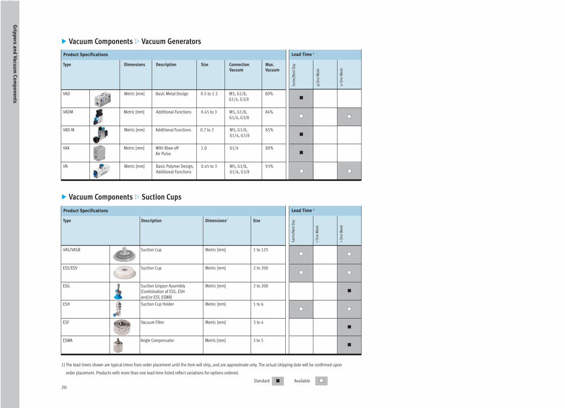
� Vacuum Components � Vacuum Generators
Sam
e/N
ext
Day
≤O
ne W
eek
>O
ne W
eek
Lead Time 1Product Specifications
VAD Metric [mm] Basic Metal Design 0.5 to 1.5 M5, G1/8, 80%
G1/4, G3/8
VADM Metric [mm] Additional Functions 0.45 to 3 M5, G1/8, 84%
G1/4, G3/8
VAD-M Metric [mm] Additional Functions 0.7 to 2 M5, G1/8, 85%
G1/4, G3/8
VAK Metric [mm] With Blow-off 1.0 G1/4 80%
Air Pulse
VN Metric [mm] Basic Polymer Design, 0.45 to 3 M5, G1/8, 93%
Additional Functions G1/4, G3/8
� Vacuum Components � Suction Cups
�
�
�
��
����
��
�� ��
Type Description Dimensions2 Size
Sam
e/N
ext
Day
< O
ne W
eek
> O
ne W
eek
Lead Time 1Product Specifications
VAS/VASB Suction Cup Metric [mm] 1 to 125
ESS/ESV Suction Cup Metric [mm] 2 to 200
ESG Suction Gripper Assembly Metric [mm] 2 to 200
(Combination of ESS, ESH
and/or ESF, ESWA)
ESH Suction Cup Holder Metric [mm] 1 to 6
ESF Vacuum Filter Metric [mm] 3 to 4
ESWA Angle Compensator Metric [mm] 3 to 5
1) The lead times shown are typical times from order placement until the item will ship, and are approximate only. The actual shipping date will be confirmed upon
order placement. Products with more than one lead-time listed reflect variations for options ordered.
Standard Available� ��
Grip
pe
rs an
d V
acu
um
Co
mp
on
en
ts
PROLandscape 11/13/06 9:24 AM Page 21

21
�
����
�
�
�
�
�
Type Description Specification
� Vacuum Components � Gauges and Accessories
Sam
e/N
ext
Day
≤O
ne W
eek
>O
ne W
eek
Lead Time 1Product Specifications
VAM Vacuum Gauge Pressure -1 to 0 bar
FVAM Vacuum Gauge with Pressure -1 to 0 bar
Flaunge Mount
ESF Vacuum Filter For Holder Sizes 3 or 4
ESWA Angle Compensator For Holder Sizes 3, 4 or 5
ISV Vacuum Efficiency Valve Pressure 4 to 6 bar
U Silencer Connection NPT or ISO
VAL Height Compensator For compensation length
5, 10 or 20mm
1) The lead times shown are typical times from order placement until the item will ship, and are approximate only. The actual shipping date will be confirmed upon
order placement. Products with more than one lead-time listed reflect variations for options ordered.
Standard Available� ��
VacuumComponents
Grip
pe
rs an
d V
acu
um
Co
mp
on
en
ts
PROLandscape 11/13/06 9:24 AM Page 22

Engineering Support
� Cylinder Sizing by Piston Force . . . . . .23
� Buckling Load . . . . . . . . . . . . . . . . . . . .24
� Air Consumption and Quality . . . . . . .25
PROLandscape 11/13/06 9:24 AM Page 23

23
Metric Series
Piston Force1 (N)
Inch Series
Piston Force1 (lbf)
Operating Pressure (bar)
1 2 3 4 5 6 7 8 9 10 11 12
2.5 0.4 0.9 1.3 1.8 2.2 2.7 3.1 3.5 4.0 4.4 4.9 5.3
3.5 0.9 1.7 2.6 3.5 4.3 5.2 6.1 6.9 7.8 8.7 9.5 10.4
5.35 2.0 4.0 6.1 8.1 10.1 12.1 14.2 16.2 18.2 20.2 22.3 24.3
6 2.5 5.1 7.6 10.2 12.7 15.3 17.8 20.4 22.9 25.4 28.0 30.5
8 4.5 9.0 13.6 18.1 22.6 27.1 31.7 36.2 40.7 45.2 49.8 54.3
10 7.1 14.1 21.2 28.3 35.3 42.4 49.5 56.5 63.6 70.7 77.8 84.8
12 10.2 20.4 30.5 40.7 50.9 61.1 71.3 81.4 91.6 102 112 122
16 18.1 36.2 54.3 72.4 90.5 109 127 145 163 181 199 217
20 28.3 56.5 84.8 113 141 170 198 226 254 283 311 339
25 44.2 88.4 133 177 221 265 309 353 398 442 486 530
32 72.4 145 217 290 362 434 507 579 651 724 796 869
40 113 226 339 452 565 679 792 905 1,018 1,131 1,244 1,357
50 177 353 530 707 884 1,060 1,237 1,414 1,590 1,767 1,944 2,121
63 281 561 842 1,122 1,403 1,683 1,964 2,244 2,525 2,806 3,086 3,367
80 452 905 1,357 1,810 2,262 2,714 3,167 3,619 4,072 4,524 4,976 5,429
100 707 1,414 2,121 2,827 3,534 4,241 4,948 5,655 6,362 7,069 7,775 8,482
125 1,104 2,209 3,313 4,418 5,522 6,627 7,731 8,836 9,940 11,045 12,149 13,254
160 1,810 3,619 5,429 7,238 9,048 10,857 12,667 14,476 16,286 18,096 19,905 21,715
200 2,827 5,655 8,482 11,310 14,137 16,965 19,792 22,619 25,447 28,274 31,102 33,929
250 4,418 8,836 13,254 17,671 22,089 26,507 30,925 35,343 39,761 44,179 48,597 53,014
320 7,238 14,476 21,715 28,953 36,191 43,429 50,668 57,906 65,144 72,382 79,621 86,859
Operating Pressure (psi)
15 30 45 60 75 90 105 120 135 150 165 180
3/32 0.1 0.2 0.3 0.4 0.5 0.6 0.7 0.8 0.9 1.0 1.1 1.2
1/8 0.2 0.4 0.6 0.8 1.0 1.2 1.4 1.6 1.8 1.9 2.1 2.3
7/32 0.5 0.9 1.4 1.8 2.3 2.7 3.2 3.6 4.1 4.5 5.0 5.5
1/4 0.6 1.1 1.7 2.3 2.9 3.4 4.0 4.6 5.1 5.7 6.3 6.9
5/16 1.0 2.0 3.1 4.1 5.1 6.1 7.1 8.1 9.2 10 11 12
3/8 1.6 3.2 4.8 6.4 7.9 9.5 11 12 14 15 17 19
1/2 2.3 4.6 6.9 9.2 11 13 16 18 20 22.9 25 27
5/8 4.1 8.1 12 16 20 24 28 32 36 40.7 44 48
3/4 6.4 12 19 25 31 38 44 50 57 63.6 69 76
1 9.9 19 29 39 49 59 69 79 89 99 109 119
1-1/4 16 32 48 65 81 97 113 130 146 162 179 195
1-5/8 25 50 76 101 127 152 178 203 228 254 279 305
2 39 79 119 158 198 238 278 317 357 397 437 476
2-1/2 63 126 189 252 315 378 441 504 567 630 693 756
3 101 203 305 406 508 610 711 813 915 1,017 1,118 1,220
4 158 317 476 635 794 953 1,112 1,271 1,430 1,589 1,748 1,906
5 248 496 744 993 1,241 1,489 1,738 1,986 2,234 2,482 2,731 2,979
6 406 813 1,220 1,627 2,034 2,440 2,847 3,254 3,661 4,068 4,474 4,881
8 635 1,271 1,906 2,542 3,178 3,813 4,449 5,085 5,720 6,356 6,992 7,627
10 993 1,986 2,979 3,972 4,965 5,959 6,952 7,945 8,938 9,931 10,925 11,918
12-1/2 1,627 3,254 4,881 6,508 8,136 9,763 11,390 13,017 14,645 16,272 17,899 19,526
� Cylinder Sizing by Piston ForceActuators
En
gin
ee
ring
Su
pp
ort
Piston Ømm
Piston Øinch
Table Values Based on the Equation: Force = (Pressure x Area) - Friction fource. *Assuming 1 bar = 15 psi
Friction force assumed to be 10% of force. Table reflects 0.9 multiplier.
Note 1: Piston force values in the table above are based on the extend (“push”) stroke.
Piston force values for retract (“pull”) stroke are as follows:
— Single acting piston rod cylinders retract (“pull”) piston force is based upon the spring force within cylinder.
— Double acting piston rod cylinders retract (“pull”) piston force is based upon the ratio of the piston rod diameter
to the piston diameter, resulting in piston force reductions ranging from 10%-25%.
— Rodless cylinders retract (“pull”) piston force is equal to the extend (“push”) force.
PROLandscape 11/13/06 9:24 AM Page 24

24
Engineering
Buckling Load Diagram
� Engineering Support � Buckling LoadActuators
The allowable load on the piston rod for long strokes is limited
by the buckling factor. The load must not exceed certain limits,
depending on stroke and piston rod diameter. The diagram below
is based on the following formula:
The type mounting which is most affected by buckling
force is the pivotal mount. With other mountings,
allowable load is approximately 50% greater.
Example:
Given a load of 90 lbf / 400 N
and a stroke of 12 in / 300 mm.
Find:
The minimum piston rod diameter for a DNC cylinder
for this application?
Solution:
Locate F = 90 lbf / 400 N on the Buckling Load Diagram.
Draw a vertical line to intersect the piston rod diameter plots.
Now locate h = 12 in / 300 mm and draw a horizontal line to
intersect the plots. The next largest piston rod diameter from the
intersection of the vertical and horizontal lines is 3/8 in / 10 mm.
Therefore, we find from the catalog that a standard
DNC-32-300-PPV-A cylinder (with a rod diameter of 12 mm)
is suitable for this stroke and application.
3000
2000
1000
900
800
700
600
500
400
300
200
100
90
80
70
60
50
40
30
20
10
En
gin
ee
ring
Su
pp
ort
PROLandscape 11/13/06 9:24 AM Page 25

25
Air Consumption Diagram
� Engineering Support � Air Consumption and QualityActuators
Air consumption is a part of the operating cost.
Consumption is shown in the diagram using the formula:
Example:
Cylinder DNC-50-500-PPV-A, piston dia. 50 mm, piston rod
dia. 20 mm, stroke 500 mm, operating pressure 65 psi/4.5 bar.
Find:Total Air Consumption per cycle?
Solution:
Locate the intersection of the selected piston dia. line with
the operating pressure line. Air consumption can then be
read off from the lower scale. The value thus obtained must
then be multiplied by the stroke (in cm). The reading gives
approx. 0.09 I/cm stroke x 50 cm stroke, corresponding to
an air consumption for a single stroke of 4.5 I. For the return
stroke, the volume of the piston rod must be subtracted from
the stroke volume (20 mm dia. results in 0.014 I/cm stroke
x 50 cm stroke = 0.7 Iiters). The return stroke air consumption
is thus 3.8 Iiters and air consumption for the double stroke
is 8.3 Iiters.
The air consumption values thus obtained are once again
only approximate values as sometimes - especially in the
case of higher numbers of strokes - not all the air is fully
removed from pressure-filled areas, with the result that the
actual air consumption may be considerably less.
2 3 4 5 6 7 8 9 0.1 2 3 4 5 6 7 8 9 1.0 2 3 4 5 6 7 8 9 10 2 3 4 5 6 7 8 9 1000.01
3 5 10 15 30 50 100 150 300 500 1000 1500 3000 5000 10,000 15,0002 20 200 2000
0.4
0.8
0.6
1.0
2.0
3.0
4.0
8.0
6.0
10.0
10
20
30
40
50
60
70
80
90
100
200
300
400
Air Consumption (cu in/in of stroke)
Air Consumption (l/cm of stroke)
Pis
ton
dia
me
ter
(in
)
Operating pressure psi / bar
Operating pressure psi / bar
Pis
ton
dia
me
ter
(mm
)
Operating pressure psi / bar
30/2 60/4 90/6 120/ 150/10180/1212.0
Air Quality Classes in Accordance with ISO 8573
Class Particle Size Max. Particulate Pressure Max. Water Max. OilDensity Dew Point Concentration Concentration
[μm] [mg/m3] [°C] [g/m3] [mg/m3]
1 0.1 0.1 -70 0.003 0.01
2 1 1 -40 0.12 0.1
3 5 5 -20 0.88 1
4 15 8 3 6.0 5
5 40 10 7 7.8 25
6 – – 10 9.4 –
7 – – Not specified Not specified –
Note: There are certain industries or applications where the quality of compressed air must be according to
specific quality classes (e.g. pharmaceutical industry, medical industry, food industry and electronics industry).
Festo Standard Recommendation for Air Quality
Compressed air quality to class: 5. 4. 2. / 4.
Solid Contaminations Class 5
Water Content Class 4
Total Oil Content
— ester based bio oils Class 2
— mineral/synthetic oils Class 4
En
gin
ee
ring
Su
pp
ort
PROLandscape 11/13/06 9:24 AM Page 26

26
Index
Pneumatic Linear Actuators, Rotary Actuators, Grippers and Vacuum ComponentsIndex
Linear Actuators
ADN . . . . . . . . . . . . . . . . . . . . . . . . . . . . . . .6
ADN-Q . . . . . . . . . . . . . . . . . . . . . . . . . . . .12
ADVC . . . . . . . . . . . . . . . . . . . . . . . . . . . . . .6
ADVU . . . . . . . . . . . . . . . . . . . . . . . . . . . . . .6
ADVU-Inch . . . . . . . . . . . . . . . . . . . . . . . . .6
ADVUL . . . . . . . . . . . . . . . . . . . . . . . . . . . .13
ADVULQ . . . . . . . . . . . . . . . . . . . . . . . . . .12
ADVULQ - Inch . . . . . . . . . . . . . . . . . . . . .12
AEN . . . . . . . . . . . . . . . . . . . . . . . . . . . . . . .5
AEN-Q . . . . . . . . . . . . . . . . . . . . . . . . . . . .11
AEVC . . . . . . . . . . . . . . . . . . . . . . . . . . . . . .5
AEVU . . . . . . . . . . . . . . . . . . . . . . . . . . . . . .5
AEVU - Inch . . . . . . . . . . . . . . . . . . . . . . . . .5
AEVULQ . . . . . . . . . . . . . . . . . . . . . . . . . .11
AEVULQ - Inch . . . . . . . . . . . . . . . . . . . . .11
CDN . . . . . . . . . . . . . . . . . . . . . . . . . . . . .7, 9
CRDG . . . . . . . . . . . . . . . . . . . . . . . . . . .6, 9
CRDNG . . . . . . . . . . . . . . . . . . . . . . . . . .6, 9
CRDNG - Inch . . . . . . . . . . . . . . . . . . . . .6, 9
CRDSNU . . . . . . . . . . . . . . . . . . . . . . . . .6, 9
CRDNSNU - Inch . . . . . . . . . . . . . . . . . .6, 9
CRDSW . . . . . . . . . . . . . . . . . . . . . . . . . .6, 9
CRDSW - Inch . . . . . . . . . . . . . . . . . . . . .6, 9
CRHD . . . . . . . . . . . . . . . . . . . . . . . . . . .6, 9
DFC . . . . . . . . . . . . . . . . . . . . . . . . . . . . . .13
DFM . . . . . . . . . . . . . . . . . . . . . . . . . . . . . .13
DFM-B . . . . . . . . . . . . . . . . . . . . . . . . . . . .13
DFP . . . . . . . . . . . . . . . . . . . . . . . . . . . . . .12
DGC . . . . . . . . . . . . . . . . . . . . . . . . . . . . . .14
DGO . . . . . . . . . . . . . . . . . . . . . . . . . . . . . . .8
DGO - Inch . . . . . . . . . . . . . . . . . . . . . . . . .8
DGP . . . . . . . . . . . . . . . . . . . . . . . . . . . . . .14
DGP - Inch . . . . . . . . . . . . . . . . . . . . . . . .14
DLP . . . . . . . . . . . . . . . . . . . . . . . . . . . . .7, 9
DMM . . . . . . . . . . . . . . . . . . . . . . . . . . . . . .6
DMML . . . . . . . . . . . . . . . . . . . . . . . . . . . .13
DNA - Inch . . . . . . . . . . . . . . . . . . . . . . . . .6
DNC . . . . . . . . . . . . . . . . . . . . . . . . . . . . . . .6
DNC - Inch . . . . . . . . . . . . . . . . . . . . . . . . . .6
DNC-Q . . . . . . . . . . . . . . . . . . . . . . . . . . . .12
DNG . . . . . . . . . . . . . . . . . . . . . . . . . . . . . . .6
DNG - Inch . . . . . . . . . . . . . . . . . . . . . . . . .6
DNGL . . . . . . . . . . . . . . . . . . . . . . . . . . . . .12
DNGL - Inch . . . . . . . . . . . . . . . . . . . . . . .12
DPZ . . . . . . . . . . . . . . . . . . . . . . . . . . . . . .12
DPZC . . . . . . . . . . . . . . . . . . . . . . . . . . . . .12
DSL . . . . . . . . . . . . . . . . . . . . . . . . . . .15, 17
DSNU . . . . . . . . . . . . . . . . . . . . . . . . . . . . .6
DSNU - Inch . . . . . . . . . . . . . . . . . . . . . . . .6
DSNU-Q . . . . . . . . . . . . . . . . . . . . . . . . . .12
DZF . . . . . . . . . . . . . . . . . . . . . . . . . . .12, 15
DZF - Inch . . . . . . . . . . . . . . . . . . . . . .12, 15
DZH . . . . . . . . . . . . . . . . . . . . . . . . . . .12, 15
DZH - Inch . . . . . . . . . . . . . . . . . . . . .12, 15
EB . . . . . . . . . . . . . . . . . . . . . . . . . . . . . . . .8
EBS . . . . . . . . . . . . . . . . . . . . . . . . . . . . . . .8
EG . . . . . . . . . . . . . . . . . . . . . . . . . . . . . . . .5
EGZ . . . . . . . . . . . . . . . . . . . . . . . . . . . . . . .5
EMM . . . . . . . . . . . . . . . . . . . . . . . . . . . . . .5
EMML . . . . . . . . . . . . . . . . . . . . . . . . . . . .11
ESNU . . . . . . . . . . . . . . . . . . . . . . . . . . . . . .5
ESNU - Inch . . . . . . . . . . . . . . . . . . . . . . . .5
EV . . . . . . . . . . . . . . . . . . . . . . . . . . . . . . . .8
EZH . . . . . . . . . . . . . . . . . . . . . . . . . . .11, 15
HMP . . . . . . . . . . . . . . . . . . . . . . . . . . . . .12
HMPL . . . . . . . . . . . . . . . . . . . . . . . . . . . .13
HPV . . . . . . . . . . . . . . . . . . . . . . . . . . . . . .15
HSP . . . . . . . . . . . . . . . . . . . . . . . . . . . . . .15
MAS . . . . . . . . . . . . . . . . . . . . . . . . . . . . . .8
SLE . . . . . . . . . . . . . . . . . . . . . . . . . . . . . .13
SLF . . . . . . . . . . . . . . . . . . . . . . . . . . . . . .13
SLG . . . . . . . . . . . . . . . . . . . . . . . . . . . . . .14
SLM . . . . . . . . . . . . . . . . . . . . . . . . . . . . . .14
SLS . . . . . . . . . . . . . . . . . . . . . . . . . . . . . .13
SLT . . . . . . . . . . . . . . . . . . . . . . . . . . . . . .13
SPZ . . . . . . . . . . . . . . . . . . . . . . . . . . . . . .14
STA . . . . . . . . . . . . . . . . . . . . . . . . . . . . .7, 9
Rotary Actuators
DAPS . . . . . . . . . . . . . . . . . . . . . . . . . . . . .17
DRD . . . . . . . . . . . . . . . . . . . . . . . . . . . . . .17
DRE . . . . . . . . . . . . . . . . . . . . . . . . . . . . . .17
DRQ . . . . . . . . . . . . . . . . . . . . . . . . . . . . . .17
DRQD . . . . . . . . . . . . . . . . . . . . . . . . . . . .17
DSL . . . . . . . . . . . . . . . . . . . . . . . . . . .15, 17
DSM . . . . . . . . . . . . . . . . . . . . . . . . . . . . .17
DSR . . . . . . . . . . . . . . . . . . . . . . . . . . . . . .17
DSR - Inch . . . . . . . . . . . . . . . . . . . . . . . . .17
Grippers and Vacuum Components
ESF . . . . . . . . . . . . . . . . . . . . . . . . . . . . . .20
ESG . . . . . . . . . . . . . . . . . . . . . . . . . . . . . .19
ESH . . . . . . . . . . . . . . . . . . . . . . . . . . . . . .20
ESS/ESV . . . . . . . . . . . . . . . . . . . . . . . . . .20
ESWA . . . . . . . . . . . . . . . . . . . . . . . . . . . .20
FVAM . . . . . . . . . . . . . . . . . . . . . . . . . . . . .21
HGD . . . . . . . . . . . . . . . . . . . . . . . . . . . . . .19
HGDS . . . . . . . . . . . . . . . . . . . . . . . . . . . .19
HGP . . . . . . . . . . . . . . . . . . . . . . . . . . . . . .19
HGPC . . . . . . . . . . . . . . . . . . . . . . . . . . . . .19
HGPL . . . . . . . . . . . . . . . . . . . . . . . . . . . . .19
HGPM . . . . . . . . . . . . . . . . . . . . . . . . . . . .19
HGPP . . . . . . . . . . . . . . . . . . . . . . . . . . . . .19
HGPT . . . . . . . . . . . . . . . . . . . . . . . . . . . . .19
HGR . . . . . . . . . . . . . . . . . . . . . . . . . . . . . .19
HGW . . . . . . . . . . . . . . . . . . . . . . . . . . . . .19
HGWM . . . . . . . . . . . . . . . . . . . . . . . . . . . .19
ISV . . . . . . . . . . . . . . . . . . . . . . . . . . . . . . .21
U . . . . . . . . . . . . . . . . . . . . . . . . . . . . . . .21
VAD . . . . . . . . . . . . . . . . . . . . . . . . . . . . . .20
VADM . . . . . . . . . . . . . . . . . . . . . . . . . . . .20
VAD-M . . . . . . . . . . . . . . . . . . . . . . . . . . . .20
VAK . . . . . . . . . . . . . . . . . . . . . . . . . . . . . .20
VAM . . . . . . . . . . . . . . . . . . . . . . . . . . . . .21
VAS/VASB . . . . . . . . . . . . . . . . . . . . . . . .20
VN . . . . . . . . . . . . . . . . . . . . . . . . . . . . . . .20
PROLandscape 11/13/06 9:24 AM Page 27

27
Custom Designed Automation SolutionsOur experienced engineers provide complete support at every stage of your development process, including: conceptualization, analysis,
engineering, design, assembly, documentation, validation, and production.
Festo is a leading global manufacturer of pneumatic and electromechanical systems, components and controls for industrial automation, with 56 national headquarters serving more than
180 countries. For more than 80 years, Festo has continuously elevated the state of manufacturing with innovations and optimized motion control solutions that deliver higher performance,
more profitable automated manufacturing and processing equipment. Our dedication to the advancement of automation extends beyond technology to the education of current and future
automation and robotics designers with simulation tools, teaching programs, and on-site services.
Comprehensive Line of Automation ComponentsWith a comprehensive line of more than 30,000 automation components, Festo is capable of solving the most complex automation requirements.
Complete SystemsCustom Control CabinetsCustom Automation Components
PLCs and I/O DevicesPneumaticsElectromechanical
Product Range
PROLandscape 11/13/06 9:24 AM Page 28

© Copyright 2006, Festo Corporation. While every effort is made to ensure that all dimensions and specifications are correct, Festo cannot guarantee that publications are completely free of any error, in particular typing or printing errors.
Accordingly, Festo cannot be held responsible for the same. For Liability and Warranty conditions, refer to our "Terms and Conditions of Sale", available from your local Festo office. All rights reserved. No part of this publication may be
reproduced, distributed, or transmitted in any form or by any means, electronic, mechanical, photocopying or otherwise, without the prior written permission of Festo. All technical data subject to change according to technical update.
Catalog no.: 13048743
United States
Customer Resource Center
502 Earth City Expressway, Suite 125
Earth City, MO 63045
For ordering assistance,
or to find your nearest Festo Distributor,
Call: 1.800.99.FESTO
Fax: 1.800.96.FESTO
Email: [email protected]
For technical support,
Call: 1.866.GO.FESTO
Fax: 1.800.96.FESTO
Email: [email protected]
Headquarters
Festo Corporation
395 Moreland Road
P.O. Box 18023
Hauppauge, NY 11788
www.festo.com/usa
Sales Offices
Boston
120 Presidential Way, Suite 330
Woburn, MA 01801
Charlotte
4301-S Stuart Andrew Blvd.
Charlotte, NC 28217
Chicago
1441 East Business Center Drive
Mt. Prospect, IL 60056
Dallas
1825 Lakeway Drive, Suite 600
Lewisville, TX 75057
Detroit
2601 Cambridge Court, Suite 320
Auburn Hills, MI 48326
New York
395 Moreland Road
Hauppauge, NY 11788
Silicon Valley
2800 Collier Canyon Road
Livermore, CA 94551
Festo North America
Design and Manufacturing Facilities
East: 395 Moreland Road, Hauppauge, NY 11788
Central: 1441 East Business Center Drive, Mt. Prospect, IL 60056
West: 2800 Collier Canyon Road, Livermore, CA 94550
Mexico
Headquarters
Festo Pneumatic, S.A.
Av. Ceylán 3
Col. Tequesquinahuac
54020 Tlalnepantla
Edo. de México
Phone:011 52 [55] 53 21 66 00
Fax: 011 52 [55] 53 21 66 65
Email: [email protected]
www.festo.com/mx
Canada
Headquarters
Festo Inc.
5300 Explorer Drive
Mississauga, Ontario L4W 5G4
Phone: 1.905.624.9000
Fax: 1.905.624.9001
Email: [email protected]
www.festo.com/ca
Festo Worldwide
Argentina Australia Austria Belarus Belgium Brazil Bulgaria Canada Chile
China Colombia Croatia Czech Republic Denmark Estonia Finland France
Germany Great Britain Greece Hong Kong Hungary India Indonesia Iran
Ireland Israel Italy Japan Korea Latvia Lithuania Malaysia Mexico Netherlands
New Zealand Norway Peru Philippines Poland Romania Russia Serbia and
Montenegro Singapore Slovak Republic Slovenia South Africa Spain Sweden
Switzerland Taiwan Thailand Turkey Ukraine United States Venezuela
www.festo.com
PROLandscape 11/13/06 9:24 AM Page 1