Embed Size (px)
Citation preview

1
INSTALLATION AND OPERATION MANUAL
RECEIVINGThe shipment should be thoroughly inspected as soon as it is received. The signed Bill of Lading is acknowledgement by the shipping carrier as receipt of this product as listed in your invoice as being in a good condition of shipment. If any of these goods listed on this Bill of Lading are missing or damaged, do not accept goods until the shipping carrier makes a notation on the freight bill of the missing or dam-aged goods. Do this for your own protection.
BE SAFEYour new lift was designed and built with safety in mind. However, your overall safety can be increased with proper training and thoughtful operation on the part of the operator. DO NOT operate or repair this equipment without reading this manual and the important safety instructions shown inside. Keep this operation manual near the lift at all times. Make sure that ALL USERS read and understand this manual.
1645 Lemonwood Dr.Santa Paula, CA. 93060, USA
Toll Free 1-800-253-2363Tel: 1-805-933-9970
www.bendpak.com
IMPORTANT SAFETY INSTRUCTIONS SAVE THESE INSTRUCTIONS
PLEASE READ THE ENTIRE CONTENTS OF THIS MANUAL PRIOR TO INSTALLATION AND OPERATION. BY PROCEEDING WITH LIFT INSTALLATION AND OPERATION YOU AGREE THAT YOU FULLY UNDERSTAND AND COMPREHEND THE FULL CONTENTS OF THIS MANUAL. FORWARD THIS MANUAL TO ALL OPERATORS. FAILURE TO OPERATE THIS EQUIPMENT AS DIRECTED MAY CAUSE INJURY OR DEATH.
MAN REV A 07-13-2016P/N 5900370
rev B-ADDED SPEC TABLE FOR EACH LIFT-ADDED CE REQUIRED WORDING
-REPLACED SINGLE PHASE WIRING FOR WUXI UNITS-updated CE declaration-ADDED 3PH MicroSwitch and post extension breakdown
400V 50Hz SUPPLY DETAILS ARE INCLUDED WITH ELECTRICAL
CONTROL BOX. DISREGARD SUPPLY WIRING DETAILS IN THIS MANUAL
EUROPEAN USERS
ORIGINAL INSTRUCTIONS IN ENGLISH LANGUAGE
Keep this operation manual near the machine at all times. Make sure that
ALL USERS read this manual.
12,000/15,000/18,000 LB / 5443/6804/8165 KG CAPACITYSURFACE MOUNTED TWO-POST LIFTS
MODELS:XPR-12CL XPR-12CL-192 XPR-12CL-LWB XPR-12CL-LWB-192 XPR-15CL XPR-15CL-192 XPR-18CL XPR-18CL-192

2
TWO-POST SURFACE MOUNTED AUTO AND TRUCK LIFT
This instruction manual has been prepared especially for you. Your new lift is the product of over 40 years of continuous research, testing and development;
it is the most technically advanced lift on the market today.
READ THIS ENTIRE MANUAL BEFORE INSTALLATION & OPERATION BEGINS.
RECORD HERE THE LIFT ANDPOWER UNIT INFORMATION WHICH IS
LOCATED ON THE SERIAL NUMBER DATA PLATES ON THE LIFT AND
ON THE POWER UNIT
Power Unit Model # _____________Power Unit Date Of Mfg. _____________Power Unit Serial # _____________ Max Operating Pressure __2,060 PSI
This information is required when calling for parts or warranty issues.
PRODUCT WARRANTY Our comprehensive product warranty means more than a commitment to you; it’s also a commitment to the value of your new BendPak lift. For full warranty details and to register your new lift contact your nearest BendPak dealer or visit
http:/ / www.bendpak.com/ support/ warranty/
What is not covered under this warranty:a. Any failure that results from Purchaser’s abuse, neglect or failure to operate, maintain or service product in accordance with instructions provided in the owner’s manual(s) supplied.b. Any damage caused by overloading lift beyond rated capacity.c. Items or service normally required to maintain the product, i.e. lubricants, oil, etc.d. Items considered general wear parts such as rubber pads, lifting cables, etc. unless wear or failure is a direct result of manufacturer defect due to material and/or workmanship.e. Any component damaged in shipment or any failure caused by installing or operating lift under conditions not in accordance with installation and operation guidelines or damaged by contact with tools or surroundings.f. Motor or pump failure caused by rain, excessive humidity, corrosive environments or other contaminants.g. Rusted components due to improper maintenance or corrosive environments.h. Cosmetic defects that do not interfere with product functionality.i. Damage due to incorrect voltage or improper wiring.j. Any incidental, indirect, or consequential loss, damage or expense that may result from any defect, failure or malfunction of BendPak Inc. product. k. All electrical components (excluding power unit) are guaranteed for one year against defects in workmanship and/or materials when the lift is installed and used according to specifications.
NOTE:Every effort has been taken to ensure complete and accurate instructions have been included in this manual, however, possible product updates, revisions and or changes may have occurred since this printing. BendPak Ranger reserves the right to change specifications
without incurring any obligation for equipment previously or subsequently sold. Not responsible for typographical errors.

3
IMPORTANT NOTICE
Do not attempt to install this lift if you have never been trained on basic automotive lift installation procedures. Never attempt to lift components without proper lifting tools such as forklift or cranes. Stay clear of any moving parts that can fall and cause injury. These instructions must be followed to ensure proper installation and opera-tion of your lift. Failure to comply with these instructions can result in serious bodily harm and void product war-ranty. Manufacturer will assume no liability for loss or damage of any kind, expressed or implied resulting from improper installation or use of this product.
PLEASE READ ENTIRE MANUAL PRIOR TO INSTALLATION
DEFINITIONS OF HAZARD LEVELS
Identify the hazard levels used in this manual with the following definitions and signal words:
Watch for this symbol: It Means: Immediate hazards which will result in severe personal injury or death.
Watch for this symbol: It Means: Hazards or unsafe practices which could result in severe personal
injury or death.
Watch for this symbol: It Means: Hazards or unsafe practices which may result in minor personal injury,
product or property damage.
OWNER’S RESPONSIBILITYTo maintain the lift and user safety, the responsibility of the owner is to read and follow these instructions:
t Follow all installation and operation instructions.t Make sure installation conforms to all applicable Local, State, and Federal Codes, Rules, and Regulations; such as State and Federal OSHA Regulations and Electrical Codes.t Carefully check the lift for correct initial function.t Read and follow the safety instructions. Keep them readily available for machine operators.t Make certain all operators are properly trained, know how to safely and correctly operate the unit, and are properly supervised.t Allow unit operation only with all parts in place and operating safely.t Carefully inspect the unit on a regular basis and perform all maintenance as required.t Service and maintain the unit only with authorized or approved replacement parts.t Keep all instructions permanently with the unit and all decals on the unit clean and visible.
BEFORE YOU BEGIN
Receiving:The shipment should be thoroughly inspected as soon as it is received. The signed bill of lading is acknowledgement by the carrier of receipt in good condition of shipment covered by your invoice. If any of the goods called for on this bill of lading are shorted or damaged, do not accept them until the carrier makes a notation on the freight bill of the shorted or damaged goods. Do this for your own protection.
NOTIFY THE CARRIER AT ONCE if any hidden loss or damage is discovered after receipt and request the carrier to make an inspection. If the carrier will not do so, prepare a signed statement to the effect that you have notified the carrier (on a specific date) and that the carrier has failed to comply with your request.
IT IS DIFFICULT TO COLLECT FOR LOSS OR DAMAGE AFTER YOU HAVE GIVEN THE CARRIER A CLEAR RECEIPT. File your claim with the carrier promptly. Support your claim with copies of the bill of lading, freight bill, invoice, and photographs, if available. Our willingness to assist in helping you process your claim does not make BendPak responsible for collection of claims or replace-ment of lost or damaged materials.

4
TABLE OF CONTENTSContents Page No.
Warranty / Serial Number Information . . . . . . . . . . . . . . . . . . . . . . . . . . . . . . . . . . . . . . . . . . . . . . . . . . . . . . . . . . . . . . 2
Definitions of Hazard Levels . . . . . . . . . . . . . .. . . . . . . . . . . . . . . . . . . . . . . . . . . . . . . . . . . . . . . . . . . . . . . . . . . . . . . . 3
Owner’s Responsibility . . . . . . . . . . . . . . .. . . . . . . . . . . . . . . . . . . . . . . . . . . .. . . . . . . . . . . . . . . . . . . . . . . . . . . . . . . . 3
Before You Begin . . . . . . . . . . . . . . . . . . . . . . . . . . . . . . . . . . . . . . . . . . . . . . . . . . . . . . . . . . . . . . . . . . . . . . . . . . . . . 3
Installer/Operator Agreement/ Protective Equipment . . . . . . . . . . . . . . . . . . . . . . . . . . . . . . . . . . . . . . . . . . . . . . . . . 5
Safety / Warning Instructions . . . . . . . . . . . . . . . . . . . . . . . . . . . . . . . . . . . . . . . . . . . . . . . . . . . . . . . . . . . . . . . . . . . . . 6
Tools Required . . . . . . . . . . . . . . . . . . . . . . . . . . . . . . . . . . . . . . . . . . . . . . . . . . . . . . . . . . . . . . . . . . . . . . . . . . . . . . . 7
Step 1 / Selecting Site . . . . . . . . . . . . . . . . . . . . . . . . . . . . . . . . . . . . . . . . . . . . . . . . . . . . . . . . . . . . . . . . . . . . . . . . . . 7
Step 2 / Floor Requirements / Concrete Specifications . . . . . . . . . . . . . . . . . . . . . . . . . . . . . . . . . . . . . . . . . . . . . . . . . . . . . . . 7
Assembly View / Description of Parts . . . . . . . . . . . . . . . . . . . . . . . . . . . . . . . . . . . . . . . . . . . . . . . . . . . . . . . . . . . . . . 8
Floor Plan . . . . . . . . . . . . . . . . . . . . . . . . . . . . . . . . . . . . . . . . . . . . . . . . . . . . . . . . . . . . . . . . . . . . . . . . . . . . . . . 9-10
Clearances . . . . . . . . . . . . . . . . . . . . . . . . . . . . . . . . . . . . . . . . . . . . . . . . . . . . . . . . . . . . . . . . . . . . . . . . . . . . . 11
Step 3 / Column Preparation . . . . . . . . . . . . . . . . . . . . . . . . . . . . . . . . . . . . . . . . . . . . . . . . . . . . . . . . . . . . . . . 12-13
Equalizer Cable Routing . . . . . . . . . . . . . . . . . . . . . . . . . . . . . . . . . . . . . . . . . . . . . . . . . . . . . . . . . . . . . . 13
Hose Routing . . . . . . . . . . . . . . . . . . . . . . . . . . . . . . . . . . . . . . . . . . . . . . . . . . . . . . . . . . . . . . . . . . . . . . . . . . . . . . . . . . 14
Step 4 / Site Layout . . . . . . . . . . . . . . . . . . . . . . . . . . . . . . . . . . . . . . . . . . . . . . . . . . . . . . . . . 15
Step 5 / Installing Power Side Column . . . . . . . . . . . . . . . . . . . . . . . . . . . . . . . . . . . . . . . . . . . . . . . . . . .16
Step 6 / Installing Off Side Column . . . . . . . . . . . . . . . . . . . . . . . . . . . . . . . . . . . . . . . . . . . . . . . . . . . . . . . 16
Step 7 / Mounting The Overhead Assembly . . . . . . . . . . . . . . . . . . . . . . . . . . . . . . . . . . . . . . . . . . . . . . . . . . . . 17
Step 8 / Mounting The Hydraulic Power Unit . . . . . . . . . . . . . . . . . . . . . . . . . . . . . . . . . . . . . . . . . . . . . . . .17-18
Step 9 / Installing the Safeties and Safety Cable . . . . . . . . . . . . . . . . . . . . . . . . . . . . . . . . . . . . . . . . . 18-19
Step 10 / Installing Hydraulic Lines . . . . . . . . . . . . . . . . . . . . . . . . . . . . . . . . . . . . . . . . . . . . . . . . . . . . . . . . . . . . . 20
Step 11 / Routing the Equalizer Cables . . . . . . . . . . . . . . . . . . . . . . . . . . . . . . . . . . . . . . . . . . . . . . . . . . . . . . . 20-21
Step 12 / Installing Overhead Microswitch . . . . . . . . . . . . . . . . . . . . . . . . . . . . . . . . . . . . . . . . . . . . . . . . . . . 21-22
Step 13 / Installing Power Unit Hose Assembly and Power Side Safety Cover . . . . . . . . . . . . . . . . . . . . . . . . 22-23
Step 14 / Installing the Lift Arms . . . . . . . . . . . . . . . . . . . . . . . . . . . . . . . . . . . . . . . . . . . . . . . . . . . . . . . 23-24
Carriage Stop Bolt Installation Warning. . . . . . . . . . . . . . . . . . . . . . . . . . . . . . . . . . . . . . . . . . . . . . . . . . . . . . . . . 25
Step 15 / Power Unit Connection . . . . . . . . . . . . . . . . . . . . . . . . . . . . . . . . . . . . . . . . . . . . . . . . . . . . . . . . . . . . . 26-28
Step 16 / Lift Start Up Final Adjustments . . . . . . . . . . . . . . . . . . . . . . . . . . . . . . . . . . . . . . . . . . . . . . . . . . . . . . . . . . . . . 28
Post Installation Checklist . . . . . . . . . . . . . . . . . . . . . . . . . . . . . . . . . . . . . . . . . . . . . . . . . . . . . . . . . . . . . . . . . . . . . . . . . 29
Step 17 / Lubrication. . . . . . . . . . . . . . . . . . . . . . . . . . . . . . . . . . . . . . . . . . . . . . . . . . . . . . . . . . . . . . . . . . . . . . . . . . . 29
Step 18 / Bleeding the Cylinders . . . . . . . . . . . . . . . . . . . . . . . . . . . . . . . . . . . . . . . . . . . . . . . . . . . . . . . . . . . . . . 29
Optional Equipment Installation. . . . . . . . . . . . . . . . . . . . . . . . . . . . . . . . . . . . . . . . . . . . . . . . . . . . . . . . . . . . . . . . . . 30-32
Step 19 / Operation/ Maintenance . . . . . . . . . . . . . . . . . . . . . . . . . . . . . . . . . . . . . . . . . . . . . . . . . . . . . . . . . . . . 33-43
Troubleshooting Guide . . . . . . . . . . . . . . . . . . . . . . . . . . . . . . . . . . . . . . . . . . . . . . . . . . . . . . . . . . . . . . . . . . . . . . 44-47
Torque Recommendations . . . . . . . . . . . . . . . . . . . . . . . . . . . . . . .. . . . . . . . . . . . . . . . . . . . . . . . . . . . . . . 47
Installation Form . . . . . . . . . . . . . . . . . . . . . . . . . . . . . . . . . . . . . . . . . . . . . . . . . . . . . . . . . . . . . . . . . . . . . . . . . . . . . 48
Part Number Lists . . . . . . . . . . . . . . . . . . . . . . . . . . . . . . . . . . . . . . . . . . . . . . . . . . . . . . . . . . . . . . . . . . . . . . . . . 49-74
CE Certificate . . . . . . . . . . . . . . . . . . . . . . . . . . . . . . . . . . . . . . . . . . . . . . . . . . . . . . . . . . . . . . 75
Certificate of Compliance . . . . . . . . . . . . . . . . . . . . . . . . . . . . . . . . . . . . . . . . . . . . . . . . . . . . . . . . . . . . . . 76
Warranty . . . . . . . . . . . . . . . . . . . . . . . . . . . . . . . . . . . . . . . . . . . . . . . . . . . . . . . . . . . . 77

5
INSTALLER / OPERATORPLEASE READ AND FULLY UNDERSTAND.
BY PROCEEDING YOU AGREE TO THE FOLLOWING:
t I have visually inspected the site where the lift is to be installed and verified the concrete to be in good condi-tion and free of cracks or other defects. I understand that installing a lift on cracked or defective concrete could cause lift failure resulting in personal injury or death.
t I understand that a level floor is required for proper installation and level lifting.
t I understand that I am responsible if my floor is of questionable slope and that I will be responsible for all charges related to pouring a new level concrete slab if required and any charges.
t I understand that Bendpak lifts are supplied with concrete fasteners meeting the criteria of the American National Standard “Automotive Lifts - Safety Requirements for Construction, Testing, and Validation” ANSI/ALI ALCTV-2011, and that I will be responsible for all charges related to any special regional structural and/or seismic anchoring requirements specified by any other agencies and/or codes such as the Uniform Building Code (UBC) and/or International Building Code (IBC).
t I will assume full responsibility for the concrete floor and condition thereof, now or later, where the above equipment model(s) are to be installed. Failure to follow danger, warning, and caution instructions may lead to serious personal injury or death to operator or bystander or damage to property.
t I understand that BendPak lifts are designed to be installed in indoor locations only. Failure to follow instal-lation instructions may lead to serious personal injury or death to operator or bystander or damage to property or lift.
Failure to follow danger, warning, and caution instructions may lead to serious personal injury or death
to operator or bystander or damage to property.
Please read entire manual prior to installation. Do not operate this machine until you read and understand
all the dangers, warnings and cautions in this manual. For additional copies or further information, contact:
BendPak Inc. / Ranger Products
1645 Lemonwood Dr.
Santa Paula, CA. 93060
1-805-933-9970
www.bendpak.com
INSTALLER / OPERATORPROTECTIVE EQUIPMENT
Personal protective equipment helps makes installa-tion and operation safer, however, it does not take the place of safe operating practices. Always wear durable work clothing during any installation and/or service activity. Shop aprons or shop coats may also be worn, however loose fitting clothing should be avoided. Tight fitting leather gloves are recommended to protect technician hands when handling parts. Sturdy leather work shoes with steel toes and oil resis-tant soles should be used by all service personnel to help pre-vent injury during typical installation and operation activities.
Eye protection is essential during installation and opera-tion activities. Safety glasses with side shields, goggles, or face shields are acceptable. Everyday eyeglasses only have impact resistant lenses, they are not safety glasses. Back belts provide support during lifting activities and are also helpful in providing worker protection. Consideration should also be given to the use of hearing protection if service activity is performed in an enclosed area, or if noise levels are high.
THIS SYMBOL POINTS OUT IMPORTANT SAFETY INSTRUCTIONS WHICH IF NOT FOLLOWEDCOULD ENDANGER THE PERSONAL SAFETY AND/OR PROPERTY OR YOURSELF AND OTHERSAND CAN CAUSE PERSONAL INJURY OR DEATH. READ AND FOLLOW ALL INSTRUCTIONS IN
THIS MANUAL BEFORE ATTEMPTING TO OPERATE THIS MACHINE.

6
INTRODUCTION
1. Read and understand all instructions and all safety warn-ings before operating lift.2. Care must be taken as burns can occur from touching hot parts.3. Do not operate equipment with a damaged cord or if the equipment has been dropped or damaged until it has been examined by a qualified service person.4. Do not let a cord hang over the edge of the table, bench, or counter or come in contact with hot manifolds or moving fan blades.5. If an extension cord is necessary, a cord with a current rating equal to or more than that of the equipment should be used. Cords rated for less current than the equipment may overheat. Care should be taken to arrange the cord so that it will not be tripped over or pulled.6. Always unplug equipment from electrical outlet when not in use. Never use the cord to pull the plug from the outlet. Grasp plug and pull to disconnect.7. Let equipment cool completely before putting away. Loop cord loosely around equipment when storing.8. To reduce the risk of fire, do not operate equipment in the vicinity of open containers of flammable liquids (gasoline).9. Adequate ventilation should be provided when working on operating internal combustion engines.10. Keep hair, loose clothing, fingers, and all parts of body away from moving parts. Keep feet clear of lift when lowering. Avoid pinch points.11. DANGER! To reduce the risk of elec-tric shock, do not use on wet surfaces or expose to rain. The power unit used on this lift contains high voltage. Disconnect power at the receptacle or at the circuit breaker switch before performing any elec-trical repairs. Secure plug so that it cannot be accidentally plugged in during service. or mark circuit breaker switch so that it cannot be accidentally switched on during service.12. Use only as described in this manual. Use only manufacturer’s recommended attachments.
13. ALWAYS WEAR SAFETY GLASSES. Everyday eyeglasses only have impact resistant lenses, they are not safety glasses.14. Consider work environment. Keep work area clean. Cluttered work areas invite injuries. Keep areas well lit.15. Guard against electric shock. This lift must be grounded while in use to protect operator from electric shock. Never connect the green power cord wire to a live terminal. This is for ground only.16. Only trained operators should operate this lift. All non-trained personnel should be kept away from the work area. Never let non-trained personnel come in contact with, or operate lift.17. DO NOT override self-closing lift controls.18. Clear area if vehicle is in danger of falling.19. ALWAYS make sure the safeties are engaged before attempting to work on or near a vehicle.21. WARNING! RISK OF EXPLOSION. This equipment has internal arcing or sparking parts which should not be exposed to flammable vapors. This machine should not be located in a recessed area or below floor level.22. MAINTAIN WITH CARE. Keep lift clean for better and safer performance. Follow manual for proper lubrication and maintenance instructions. Keep control han-dles and/or buttons dry, clean and free from grease and oil.23. Check for damaged parts. Check for alignment of moving parts, breakage of parts or any condition that may affect operation of lift. Do not use lift if any component is broken or damaged.24. NEVER remove safety related components from the lift. Do not use lift if safety related components are missing or damaged.23. STAY ALERT. Use common sense and watch what you are doing. Remember, SAFETY FIRST.
SAVE THESE INSTRUCTIONS
1. Carefully remove the crating and packing materials. CAUTION! Be careful when cutting steel banding material as items may become loose and fall causing personal harm or injury.
2. Check the voltage, phase and proper amperage requirements for the motor shown on the motor plate. Wiring should be performed by a certified electrician only.
IMPORTANT SAFETY INSTRUCTIONS Read these safety instructions entirely.
IMPORTANT NOTICE Do not attempt to install this lift if you have never been trained on basic automotive lift installation procedures.
Never attempt to lift components without proper lifting tools such as forklift or cranes. Stay clear of any moving parts that can fall and cause injury.

7
STEP 1(Selecting Site)
Before installing your new lift, check the following.
1. LIFT LOCATION: Always use architects plans when available. Check layout dimension against floor plan requirements making sure that adequate space if avail-able.
2. OVERHEAD OBSTRUCTIONS: The area where the lift will be located should be free of overhead obstruc-tions such as heaters, building supports, electrical lines etc.
3. DEFECTIVE FLOOR: Visually inspect the site where the lift is to be installed and check for cracked or defec-tive concrete.
4. OPERATING TEMPERATURE. Operate lift only between temperatures of 41° -104° F.
5. Lift is designed for INDOOR INSTALLATION ONLY. Outdoor use permitted only if covered and dry. Always
follow warnings illustrated on equipment labels.
STEP 2(Floor Requirements)
This lift must be installed on a solid level concrete floor with no more than 3-degrees of slope. Failure to do so could cause personal injury or death.
A level floor is suggested for proper use and installation and level lifting. If a floor is of questionable slope, consider a survey of the site and/or the possibility of pouring a new level concrete slab.
t DO NOT install or use this lift on any asphalt surface or any surface other than concrete.
t DO NOT install or use this lift on expansion seams or on cracked or defective concrete.
t DO NOT install or use this lift on a second / elevated floor without first consulting building architect.
LIFT MODEL CONCRETE REQUIREMENTS
12,000 Lb Models 6” Min. Thickness / 3,000 PSI 15,000 Lb Models 6” Min. Thickness / 3,000 PSI 18,000 Lb Models 8” Min. Thickness / 3,000 PSI
All models MUST be installed on 3000 PSI concrete only conforming to the minimum requirements shown above.
New concrete must be adequately cured by at least 28 days minimum.
IMPORTANT NOTICEThese instructions must be followed to ensure proper installation and operation of your lift. Failure
to comply with these instructions can result in serious bodily harm and void product warranty. Manufacturer will assume no liability for loss or damage of any kind, expressed or implied resulting
from improper installation or use of this product.PLEASE READ ENTIRE MANUAL PRIOR TO INSTALLATION
t Rotary Hammer Drill or Similar t 3/4” Masonry Bit t Hammert 4 Foot Levelt Open-End Wrench Set: SAE/Metrict Socket And Ratchet Set: SAE/Metrict Hex-Key / Allen Wrench Set
t Large Crescent Wrencht Large Pipe Wrencht Crow Bar t Chalk Linet Medium Flat Screwdrivert Tape Measure: 25 Foot Minimumt Needle Nose Pliers
TOOLS REQUIRED
IMPORTANT NOTE:BendPak lifts are supplied with installation instructions and concrete fasteners meeting the criteria as prescribed
by the American National Standard "Automotive Lifts - Safety Requirements for Construction, Testing, and Validation" ANSI/ALI ALCTV-2011. Lift buyers are responsible for any special regional structural and/or seismic an-choring requirements specified by any other agencies and/or codes such as the Uniform Building Code (UBC) and/
or International Building Code (IBC).
CONCRETE SPECIFICATIONS

8
PARTS INVENTORYBe sure to take a complete inventory of parts prior to beginning installation.
Description QtyOverhead Assembly 1
Arm Assemblies 4Frame Contact Pads 4Frame Cradle Pads 4
Offside Column with Lift Head Assembly 1Powerside Column with Lift Head Assembly 1
Column Extension Weldments (-192 Models ONLY) 2Hydraulic Cylinder 2
Parts Box (Packing List Enclosed) 1Parts Bag (Packed in Part Box) 1Hydraulic Power Unit 1
When removing the lift from shipping angles pay close attention as the posts can slide and can cause injury. Prior to removing the bolts make sure the posts are held securely by a fork lift or some other heavy lifting devise.
Off Side Column Assembly
Overhead Assembly
Telescoping Screw Pad
Stacking PadAdapters
Frame CradlePad
HydraulicPower Unit
ArmAssemblies
Power Side Column Assembly
Column ExtensionWeldments

9
FLOOR PLAN
MODEL XPR-12CL XPR-12CL-192 XPR-12CL-LWB XPR-12CL-LWB-192
Lifting Capacity 12,000Lbs. / 5443Kg. 12,000Lbs. / 5443Kg. 12,000Lbs./ 5443Kg. 12,000Lbs. / 5443Kg.
Max Capacity/ Front Axle 6,000 lbs. / 2722 Kg. 6,000 lbs. / 2722 Kg. 6,000 lbs. / 2722 Kg. 6,000 lbs. / 2722 Kg.
Max Capacity/ Rear Axle 6,000 lbs. / 2722 Kg. 6,000 lbs. / 2722 Kg. 6,000 lbs. / 2722 Kg. 6,000 lbs./ 2722 Kg.
A- Height Overall: 170" / 4318 mm. (*) 192.7" / 4895 mm. 170” / 4318 mm. (*) 192.7” / 4895 mm.B -Width Overall 155" / 3937 mm. 155" / 3937 mm. 155" / 3937 mm. 155" / 3937 mm. D- Floor to Overhead Switch: 165" / 4191 mm. (*) 187.7" / 4768 mm. 165" / 4191 mm. (*) 187.7” / 4768 mm.
F -Reach (Front Arm Min.): 32" / 813 mm. 32” / 813 mm. 35-1/2" / 902 mm. 35-1/2" / 902 mm.
G -Reach (Front Arm Max.): 60" / 1524 mm. 60” / 1524 mm. 71-1/2" / 1819 mm. 71-1/2" / 1819 mm.
H- Reach (Rear Arm Min.): 32" / 813 mm. 32” / 813 mm. 35-1/2" / 902 mm. 35-1/2" / 902 mm.
I- Reach (Rear Arm Max.): 60" / 1524 mm. 60” / 1524 mm. 71-1/2" / 1819 mm. 71-1/2" / 1819 mm.
J- Min. Pad Height: 5" / 127 mm. 5” / 127 mm. 5” / 127 mm. 5” / 127 mm.
K- Rise: 69" / 1753 mm. 69" / 1753 mm. 69" / 1753 mm. 69" / 1753 mm.
L -Max Lift Height (Pad Only): 74" / 1880 mm. 74” / 1880 mm. 74” / 1880 mm. 74” / 1880 mm.
M - Max Lift Height (6" Adapter): 80" / 2032 mm. 80” / 2032 mm. 80” / 2032 mm. 80” / 2032 mm.
Standard Motor(**) 220VAC / 60Hz.1Ph. 220VAC / 60Hz.1Ph. 220VAC / 60Hz.1Ph. 220VAC / 60Hz.1Ph.
Time of Full Rise: 45 Seconds 45 Seconds 45 Seconds 45 Seconds
Max Load Per Arm: 3,000 Lbs." / 1361 Kg. 3,000 Lbs." / 1361 Kg. 3,000 Lbs." / 1361 Kg. 3,000 Lbs." / 1361 Kg. Emission sound pressure at Operator Position < 70 dB(A)
* An optional bolt-on top extension for column raises the overhead bar an additional 24”. Must be ordered from factory at time of order.
** For CE compliant countries see errata sheet included with control panel.
The design, material and specifications are subject to change without notice.

10
FLOOR PLAN
MODEL XPR-15CL XPR-15CL-192 XPR-18CL XPR-18CL-192
Lifting Capacity 15,000Lbs. / 6804Kg. 15,000Lbs. / 6804Kg. 18,000Lbs. / 8165Kg. 18,000Lbs. / 8165Kg.
Max Capacity/ Front Axle 7,500 lbs. / 3402 Kg. 7,500 lbs. / 3402 Kg. 9,000 lbs. / 4082 Kg. 9,000 lbs. / 4082 Kg.
Max Capacity/ Rear Axle 7,500 lbs. / 3402 Kg. 7,500 lbs. / 3402 Kg. 9,000 lbs. / 4082 Kg. 9,000 lbs. / 4082 Kg.
A- Height Overall: 170" / 4318 mm. (*) 192.7" / 4895 mm. 170” / 4318 mm. (*) 192.7” / 4895 mm. B -Width Overall 155" / 3937 mm. 155" / 3937 mm. 155" / 3937 mm. 155" / 3937 mm. D- Floor to Overhead Switch: 165" / 4191 mm. (*) 187.7” / 4768 mm. 165" / 4191 mm. (*) 187.7” / 4768 mm.
F -Reach (Front Arm Min.): 39" / 991 mm. 39” / 991 mm. 39” / 991 mm. 39” / 991 mm.
G -Reach (Front Arm Max.): 60" / 1524 mm. 60” / 1524 mm. 60” / 1524 mm. 60” / 1524 mm.
H- Reach (Rear Arm Min.): 39" / 991 mm. 39” / 991 mm. 39” / 991 mm. 39” / 991 mm.
I- Reach (Rear Arm Max.): 60" / 1524 mm. 60” / 1524 mm. 60” / 1524 mm. 60” / 1524 mm.
J- Min. Pad Height: 5" / 127 mm. 5” / 127 mm. 5” / 127 mm. 5” / 127 mm.
K- Rise: 69" / 1753 mm. 69" / 1753 mm. 69" / 1753 mm. 69" / 1753 mm.
L -Max Lift Height (Pad Only): 74" / 1880 mm. 74” / 1880 mm. 74” / 1880 mm. 74” / 1880 mm.
M - Max Lift Height (6" Adapter): 80" / 2032 mm. 80” / 2032 mm. 80” / 2032 mm. 80” / 2032 mm.
Standard Motor(**) 220VAC / 60Hz.1Ph. 220VAC / 60Hz.1Ph. 220VAC / 60Hz.1Ph. 220VAC / 60Hz.1Ph.
Time of Full Rise: 45 Seconds 45 Seconds 45 Seconds 45 Seconds
Max Load Per Arm: 3,750 Lbs. / 1701 Kg. 3,750 Lbs. / 1701 Kg. 4,500 Lbs. / 2041 Kg 4,500 Lbs. / 2041 KgEmission sound pressure at Operator Position < 70 dB(A)
* An optional bolt-on top extension for column raises the overhead bar an additional 24”. Must be ordered from factory at time of order.
** For CE compliant countries see errata sheet included with control panel.
The design, material and specifications are subject to change without notice.

11
XPR-12CL/15CL/18CL
LIFT HEIGHT CLEARANCE NOTE: There must be a 1” MIN distance from top of lift to nearest obstruction.
CLEARANCES
APPROACH

12
STEP 3(Column Preparation)
COMPLETE THE FOLLOWINGPRIOR STANDING UP COLUMNS.
1. Slide Lift Head up Column to aid in Pulley removal and Equalizer Cable routing. (See Fig 3.1)
2. Temporarily remove the cable sheaves located at the inside bottom of each Column. (Fig. 3.2)
3. Route the button around the bottom sheave and secure at the carriage lock plate located inside each Lift Head. Route threaded end of cable upwards through the bottom of the carriage. Leave excess cable resting on top of carriage until further steps are required. (See Fig 3.3 and 3.4)
4. Install the straight and elbow Cylinder Fittings in Cylinder Ports. Pay attention when installing the elbow fittings to ensure that each fitting points towards the side of the Column that the hose retainer clips are located on. (See Fig 3.5)
Fig 3.1
Slide Lift Head upwards
Fig 3.2
Remove cable sheaves
Threaded end of cable routed up through car-
riage towards Overhead Assembly mounting
Fig 3.3
NOTE: Portions of Carriage and Column cut away for clarity
NOTE: Column hidden for clarity
Power Side Column de-
picted Fig 3.4
Threaded cable end from other
side of lift.
Cable routed up and across Over-head Assembly to opposite carriage.
Fig 3.5
Elbow fitting must be turned towards hose clips for hy-
draulic hose routing
Notice that the hose clips are offset for
hydraulic hose routing
NOTEFOR XPR-12CL/15CL/18CL-192 MODELS FIT
EXTENSION WELDMENTS TO POST ASSEMBLY IN THIS STEP FOR EASE OF INSTALLATION
AND BOLT TOGETHER AS SHOWN ON PAGE 13 WITH M10 HARDWARE.

13
6. Route both Hoses in their respective Columns PRIOR to raising Columns to their vertical position. When routing the Hydraulic Hose through the Columns, make sure to route through the Retaining Clips welded inside each Column. Make sure that the Hose is clear of any moving parts. It may be necessary to tie Hose clear of obstruc-tions by using nylon tie straps or wire. Refer to Step 10.
BE SURE TO ROUTE THE HYDRAULIC HOSES THROUGH THE RETAINING CLIPS WELDED
INSIDE EACH COLUMN.
Fig 3.7
EQUALIZER CABLE ROUTING
Fig 3.6
M10 Hex Head Bolt
M10 Spring Lock Washer
M10 Flat Washer
M10 Hex Nut
CABLE
THREADED END
BUTTONEND

14
HOSE ROUTING

15
FLOOR PLAN
Model A Capacity XPR-12CL 155” / 3937 mm 12,000 LBSXPR-15CL 155” / 3937 mm 15,000 LBSXPR-18CL 155” / 3937 mm 18,000 LBS
APPROACH
A
STEP 4(Site Layout)
1. Determine which side of the lift will be the approach side.
2. Now determine where the power unit will be located. The POWER SIDE column has the power unit mounting bracket attached to the side.
3. Use the chart on page 13 to determine which lift width layout you would like to use.
4. Once a location is determined, use a carpenters chalk
line to layout an alignment line for the Column locations. Keep all dimensions square within 1/8” (3mm) or malfunc-tioning of the lift can occur. (See Fig 4.1)
5. After the Column locations are properly marked, use chalk or crayon to make an outline of the posts on the floor at each Column location using the Column base plates as a template.
6. CHECK ALL DIMENSIONS TWICE and make sure that the layout is perfectly square.
Fig 4.1.USE BASE PLATE EDGES TO ALIGN POSTS
CHALK LINE

16
STEP 5(Installing The POWERSIDE Column)
1. Before proceeding, double the check measurements and make certain that the bases of each Column are aligned with the chalk line.
2. Using the base plate on the POWERSIDE column as a guide, drill each anchor hole in the concrete approximately 6” deep for 12K and 15K models and 8” for 18K models using a rotary hammer drill and 3/4” concrete drill-bit. To assure full holding power, do not ream the hole or allow the drill to wobble. (See Fig. 5.1)
3. After drilling, remove dust thoroughly from each hole making certain that the Column remains aligned with the chalk line.
4. Assemble the washers and nuts on the anchors then tap into each hole with a hammer until the washer rests against the Base Plate. Be sure that if shimming is required that enough threads are left exposed. (See Fig. 5.2)
5. Insert the shims as necessary under the Base Plate so that when the anchor bolts are tightened, the Columns will be plumb. (See Fig. 5.3)
6. With the shims and anchor bolts in place, tighten by securing the nut to the base then turning 3-5 full turns clockwise. DO NOT use an impact wrench for this procedure. (See Fig. 5.4)
STEP 6(Mounting The OFFSIDE Column)
1. Position the OFFSIDE Column at the designated chalk locations and secure to the floor following the same proce-dures as outlined in STEP FIVE; Items 1-6.
Fig 5.1
Fig 5.3
NOTE:BENDPAK LIFTS ARE SUPPLIED WITH INSTALLATION
INSTRUCTIONS AND CONCRETE FASTENERS MEETING THE CRITERIA AS PRESCRIBED BY THE AMERICAN NATIONAL STANDARD "AUTOMOTIVE
LIFTS - SAFETY REQUIREMENTS FOR CONSTRUCTION, TESTING, AND VALIDATION"
ANSI/ALI ALCTV-2011. LIFT BUYERS ARE RESPONSIBLE FOR ANY SPECIAL REGIONAL
STRUCTURAL AND/OR SEISMIC ANCHORING REQUIREMENTS SPECIFIED BY ANY OTHER
AGENCIES AND/OR CODES SUCH AS THE UNIFORM BUILDING CODE (UBC) AND/OR INTERNATIONAL
BUILDING CODE (IBC).
NOTE:TO EASE INSTALLATION OF THE OVERHEAD ASSEMBLY, IT HELPS TO KEEP THE ANCHOR
BOLTS LOOSE ON ONE OF THE POSTS UNTIL THE OVERHEAD ASSEMBLY IS MOUNTED.
Fig 5.2
Tap anchor bolts intoeach hole with a hammer until the washer rests against the baseplate.
Fig 5.4
Tighten Nut3- Turns.Do Not UseImpact Wrench.
NOTE:TO EASE THE INSTALLATION OF THE OVERHEAD
ASSEMBLY, IT HELPS TO KEEP THE ANCHOR BOLTS LOOSE ON ONE OF THE POSTS UNTIL THE
OVERHEAD ASSEMBLY IS MOUNTED.

17
STEP 7(Mounting the Overhead Assembly)
1. Remove all of the Equalizer pulleys in preparation of installing the Overhead Assembly.
2. Using a lifting device, raise the Overhead Assembly into position on top of the Columns. Bolt to the columns using the 10 mm Hex Bolts, Nuts and Washers.
3. YOU MUST POSITION THE SWITCH ENCLOSURE ADJACENT POWERSIDE COLUMN. (See Fig. 7.1)
4. Tighten the Overhead Assembly Bolts.
STEP 8(Mounting the Hydraulic Power Unit)
1. Attach the power unit to the POWER SIDE Column. Install the vibration dampener between the power unit and the power unit mounting plate on the Power Side Column, using four M8 hex head bolts and nuts supplied. (See Fig 8.1) 2. Fill the reservoir with 10 WT. HYDRAULIC OIL OR DEXRON ATF, approximately four gallons. Make sure the
funnel used to fill the Power Unit and unit is clean. Do not connect power unit hydraulic hose assembly at this time.
3. The standard power unit for your lift is 220 volt, 60HZ, single phase. All wiring must be performed by a certified electrician only. SEE WIRING INSTRUCTIONS AFFIXED TO MOTOR FOR PROPER WIRING INSTRUCTIONS.
NOTE:IN ORDER TO ROUTE THE EQUALIZER CABLES
THE SHEAVES MUST BE REMOVED.
IF THE ANCHOR BOLTS WERE LOOSENED TO AID ON THE INSTALLATION OF THE TOP TROUGH,
TIGHTEN ANCHOR BOLTS AS INDICATED IN STEP 5 ITEMS 4 - 7.
Fig 8.1
Vibration Dampener
M8 x1.25 x 35mm hex head bolts, M8
flat washers and M8 Nylock nuts
(Qty 4 ea)
DO NOT PERFORM ANY MAINTENANCE OR INSTALLATION OF ANY COMPONENTS WITHOUT FIRST ENSURING THAT ELECTRICAL POWER HAS
BEEN DISCONNECTED AT THE SOURCE OR PANEL AND CANNOT BE RE-ENERGIZED UNTIL ALL
MAINTENANCE AND/OR INSTALLATION PROCEDURES ARE COMPLETED.
ALL WIRING MUST BE PERFORMED BY A LICENSED ELECTRICIAN.
Position Overhead Assembly with microswitch bracket adjacent to Power
Side Column
Overhead Assembly
Off Side Column
Microswitch Bracket
Power Side Column
Fig 7.1

18
STEP 9(Installing the Safeties and Safety Cable)
1. Install safety weldments on to each respective Column. (See Figs 9.1 - 9.2)
2. From the Off Side Column insert the non-looped end of the safety cable through the hole located to the right of the Off Side safety weldment. (See Fig 9.3)
3. Route the cable under the sheave and route it towards the Overhead Assembly. (See Fig 9.4)
4. Route the cable through the Overhead Assembly’s safety sheave(s) and across the lift. (See Figs 9.5 - 9.6)
5. Route the cable the same way on the Power Side going back down the Column.
6. Route the cable over the top pin on the safety handle. Insert the cable end through the hole on the threaded pin. (See Fig 9.7)
7. Pull the slack out the safety cable and keep tension on the cable as nuts are being tightened. Tighten jam nuts on either side of the cable keeping the cable cen-tered to the hole to secure it into place. (See Fig 9.7)
DO NOT RUN POWER UNIT WITHOUT OIL. DAMAGE TO POWER UNIT PUMP CAN OCCUR. THE POWER UNIT MUST BE KEPT DRY. DAMAGE TO POWER UNIT CAUSED BY WATER OR OTHER
LIQUIDS SUCH AS DETERGENTS, ACID ETC., IS NOT COVERED UNDER WARRANTY.OPERATE LIFT ONLY BETWEEN TEMPERATURES OF 41 °- 104° F.
ANY IMPROPER ELECTRICAL INSTALLATION MAY DAMAGE POWER UNIT MOTOR AND RESULTING DAMAGE WILL NOT BE COVERED UNDER WARRANTY.
MOTOR CAN NOT RUN ON 50HZ WITHOUT A PHYSICAL CHANGE IN MOTOR.USE A SEPARATE CIRCUIT BREAKER FOR EACH POWER UNIT.
PROTECT EACH CIRCUIT WITH TIME DELAY FUSE OR CIRCUIT BREAKER.FOR 208-230 VOLT, SINGLE PHASE, USE A 25 AMP FUSE.FOR 208-230 VOLT, THREE PHASE, USE A 20 AMP FUSE.FOR 380-440 VOLT, THREE PHASE, USE A 15 AMP FUSE.
Fig 9.1
Fig 9.2
Safety Cable
Hairpin Cotter
Power Side Safety Weldment
Torsion Springs
Safety Clevis
Pin
Safety CableHairpin
Cotter Off Side Safety Weldment
Safety Clevis
Pin
Torsion Spring

19
ENSURE THAT BOTH THE POWER SIDE & OFF SIDE SAFETIES ENGAGE PROPERLY PRIOR TO
LIFT OPERATION.
Fig 9.3
Slip looped end over bottom pin
Insert non-looped end of safety cable through
hole in Column
Fig 9.4
Route safety cable under Off Side
safety sheave and up towards Overhead
Assembly
NOTE: Column cut away for clarity
Fig 9.5
Safety Cable
NOTE: Top plate cut away for clarity
Route safety cable over the top pin of the Power
Side Safety Weldment
Tighten jam nuts ensuring safety cable is
centered in hole
Route safety cable the
hole in the threaded pin
NOTE:MAKE SURE TO KEEP THE SAFETY CABLE CENTERED WHEN TIGHTENING JAM NUTS
ON SAFETY.
Fig 9.6

20
STEP 10(Installing Hydraulic Lines)
1. Install the bulkhead tee fitting into the Power Side Column. The through hole is located approximately 90 inches from the floor on the back wall of the Power Side Column.
2. Connect the Power Side cylinder hose to the tee fit-ting. Be sure to route the hose through the retainer clips inside the posts.
3. Route the Off Side cylinder hose (Crossover Hose) up through the Column and across the Overhead Assembly, down the Column and connect it to the bulkhead tee fit-ting. (See Fig 10.1)
STEP 11
(Routing the Equalizer Cables)Refer to illustrations on Page 11.
1. Raise and lock each Carriage approximately 28” above the ground. (See Fig. 11.1)
2. With the Carriages locked at 28” off the floor, route the Equalizer Cables up to the Top Trough.
3. Route the cables through the sheave brackets and reinstall the sheaves. (See Fig. 11.2)
Note: The sheaves should have been removed in Step 6.
4. Insert the threaded end of the cable through the hole on top of the carriage. Place M22 washer and M22 Nylock nut on threaded cable end. Tighten cable nuts until taut, checking that both cables have equal tension. (See Fig 11.3)
Fig 10.1
Power Hose
Crossover Hose
Bulkhead fitting
Power Side Hose
Power Side Column
WHEN ROUTING THE HYDRAULIC HOSE THROUGH
THE POSTS, MAKE SURE TO ROUTE THROUGH THE HOSE CLIPS WELDED INSIDE EACH POST. MAKE SURE THAT THE HOSE IS CLEAR OF ANY MOVING PARTS. IT MAY BE NECESSARY TO TIE
THE HOSE CLEAR BY USING NYLON TIE STRAPS OR WIRE.
Fig 10.2Route Crossover Hose through
hose clips
Microswitch wire clips
WHEN THE CABLE ADJUSTING NUTS BOTTOM OUT ON THE THREADED END OF THE CABLE
CONNECTOR AND THERE IS STILL SLACK IN THE CABLES, THE CABLES HAVE STRETCHED BEYOND
THE SAFE USEFUL LENGTH AND NEED TO BE REPLACED WITH FACTORY APPROVED CABLE
ASSEMBLIES. DO NOT PLACE WASHERS, SPACERS OR OTHER DEVICES TO “SHORTEN” THE
EFFECTIVE CABLE LENGTH AS DAMAGE TO THE LIFT OR INJURY TO PERSONS MAY OCCUR.
Fig 11.1
MAKE SURE THAT THE SAFETY LOCKS ON EACH POST ARE FULLY ENGAGED BEFORE ATTEMPTING
TO ROUTE EQUALIZER CABLES AND/OR HOSES. CARRIAGES MUST BE EQUAL HEIGHT FROM THE
FLOOR BEFORE PROCEEDING.

21
STEP 12(Installing Overhead Micro Switch)
1. Install the overhead Microswitch as shown below. Be sure to keep wire clear of moving parts. (See Fig.12.1)
Note: Second Microswitch for 3 phase wired units ONLY. 3 phase Microswitch Kit can be found in the Power Unit shipping box.
2. Route Microswitch wire though the hole in Power Side Column with rubber grommet. Loosely position Power Side safety cover and run other end of Microswitch wire through hole with grommet in Power Side safety cover. (See Fig. 12.2)
Fig. 11.3
Nylock Nut
Threaded Cable End
Threaded cable end comes down from Overhead Assembly and
into hole on top of carriage plate.
ALL WIRING MUST BE PERFORMED BY A LICENSED ELECTRICIAN.
DO NOT PERFORM ANY MAINTENANCE OR INSTALLATION OF ANY COMPONENTS WITHOUT FIRST ENSURING THAT ELECTRICAL POWER HAS
BEEN DISCONNECTED AT THE SOURCE OR AT POWER PANEL AND CANNOT BE RE-ENERGIZED UNTIL ALL MAINTENANCE AND/OR INSTALLATION
PROCEDURES ARE COMPLETED.
Fig. 11.2
Equalizer Cables
SheaveBrackets
Sheaves
MICROSWITCH WIRE MUST BE RUN THROUGH CLIPS IN POST AND OVERHEAD ASSEMBLY.
FAILURE TO DO SO CAN CAUSE DAMAGE TO LIFT OR TO VEHICLES.
Fig. 12.2
Route Microswitch wire thought holes
with grommets Power Side safety cover
Fig. 12.1
MicroswitchMicroswitch
Box
CoverCover

22
3. Route wire up through Column and across Overhead Assembly through hole in Overhead Assembly into the Microswitch box. (See Fig. 12.3)
STEP 13(Installing power unit hose assembly
and Power Side safety cover)
1. With Power Side safety cover loosely positioned route power unit hydraulic hose through clips in Power Side safety cover. (See Fig. 13.1)
2. Install the 90° fitting w/ O-ring into the power port of the power unit. Use teflon tape on the pipe fittings ONLY. Connect power unit hose assembly to the 90° w/O-ring fitting on power unit. (See Fig. 13.2)
3. Connect other end of power unit hydraulic hose assembly to the bulkhead fitting. (See Fig. 13.3)
4. After safeties have been adjusted and checked for proper operation, install and tighten Power Side safety cover and Off Side safety cover mounting screws.(See Fig. 13.4 and 13.5)
Fig. 12.3
Microswitch Wire
Microswitch Wire Clips
POWER UNIT HYDRAULIC HOSE MUST BE ROUTED THROUGH THE HOSE CLIPS IN POWER SIDE
SAFETY COVER. FAILURE TO DO SO CAN RESULT IN PERSONAL INJURY OR DAMAGE TO THE LIFT.
Fig. 13.1
Route power unit hydraulic hose through clips in Power
Side safety cover
Power Side safety cover
Fig. 13.2
Power unit 90° fitting with
O-ring
Power unit hose assembly
Fig. 13.3
Power Side
Column
Power Hose
Crossover Hose
Bulk-head fitting
Power Side Hose
Fig. 13.4
Screw
Screw
Microswitch Wire
Power unit hose assembly
Power Side Safety Cover

23
STEP 14(Installing the Lift Arms)
1. Place the lift arm assemblies in the lift heads.
2. Install the lift head pins into the lift head and through the holes in the arm assembly. (See Fig. 14.1)
3. Install the snap ring into the groove in the lift head pin on under side of the lift head. (See Fig. 14.2)
4. Place each Gear Ring against the Lift Head Pin and align the holes in the Gear Ring with the threaded holes in the Arm Ears. Ensure that the teeth on the Gear Ring mesh smoothly with the teeth on the gears of the Lift Head. (See Fig. 14.3)
5. Verify the operation of the arm restraints by pulling up on the key ring of the arm restraint pin. Pivot the arms back and forth and test the operation of the arm restraint pin in various positions. (See Fig. 14.4)
6. Ensure that the arms do not move when a force of approximately 100 pounds or less is applied laterally to the fully extended arms.
Fig. 13.5
Screw
THE ARM RESTRAINT GEARS MUST BE POSITIONED PROPERLY. CONFIRMATION OF
PROPER GEAR ENGAGEMENT MUST BE MADE PRIOR TO THE OPERATION OF THE LIFT.
PERIODIC INSPECTION IS REQUIRED. FAILURE TO INSPECT THE ARM RESTRAINT GEARS ON ALL FOUR ARMS PROPERLY CAN RESULT IN DAMAGE
TO THE VEHICLE OR INJURY AND/OR DEATH.
Lift Head Pin
Lift Head Pin
Snap Ring
Snap Ring
Lift Head
Fig. 14.1
Fig. 14.2
Lift Head Pin
Lift Head Pin
Snap Ring
Fig. 14.4
Fig. 14.3
Arm Ear threaded holes
Arm Restraint Gear Ring
Lift Head Pin

24
NOTE:EACH ARM RESTRAINT ASSEMBLY MUST BE INSPECTED BEFORE EACH AND EVERY TIME
THE LIFT IS OPERATED.
DO NOT OPERATE THE LIFT IF ANY OF THE FOUR ARM RESTRAINT SYSTEMS ARE
NOT FUNCTIONING PROPERLY.
REPLACE ANY BROKEN COMPONENTS OR COMPONENTS WITH BROKEN TEETH ONLY WITH
AUTHORIZED OR APPROVED REPLACEMENT PARTS.

25
YOU MUST RE-INSTALL TOP CARRIAGE-STOP BOLT (SHOWN BELOW). TIGHTEN CARRIAGE-STOP
BOLT TO 2-3 FT.-LBS. OF TORQUE UPON FINAL INSTALLATION INSPECTION.
THESE INSTRUCTIONS MUST BE FOLLOWED TO ENSURE PROPER INSTALLATION
AND OPERATION OF YOUR LIFT. FAILURE TO COMPLY WITH THESE INSTRUCTIONS CAN RESULT
IN SERIOUS BODILY INJURY AND/OR DEATH AND/OR VOID PRODUCT WARRANTY.
MANUFACTURER WILL ASSUME NO LIABILITY FOR LOSS OR DAMAGE OF ANY KIND, EXPRESSED
OR IMPLIED RESULTING FROM IMPROPER INSTALLATION OR USE OF THIS PRODUCT.
CARRIAGE STOP BOLT INSTALLATION

2626
IMPORTANT POWER-UNIT INSTALLATION NOTES
n DO NOT run Power Unit with no oil. Damage to pump can occur.n The Power Unit must be kept dry. Damage to Power Unit caused by water or other liquids such as detergents, acid etc., is not covered under warranty.n Improper electrical hook-up can damage motor and will not be covered under warranty.n Motor can not run on 50HZ without a physical change in motor.n Use a separate breaker for each power unit.n Protect each circuit with time delay fuse or circuit breaker.n For 208-230 volt, single phase, use a 25 amp fuse.n For 208-230 volt, three phase, use a 20 amp fuse.n For 380-440 volt, three phase, use a 15 amp fuse.
Installation and adjustment. DO NOT attempt to raise vehicle until a thorough operation check has been completed.
ALL WIRING MUST BE PERFORMED BY A CERTIFIED ELECTRICIAN ONLY.
SEE WIRING INSTRUCTIONS AFFIXED TO MOTOR FOR PROPER WIRING INSTRUCTIONS.
DO NOT PERFORM ANY MAINTENANCE OR INSTALLATION OF ANY COMPONENTS WITHOUT FIRST ENSURING THAT ELECTRICAL POWER HAS BEEN DISCONNECTED
AT THE SOURCE OR PANEL AND CANNOT BE RE-ENERGIZED UNTIL ALL MAINTENANCE AND/OR INSTALLATION PROCEDURES ARE COMPLETED.

27
28
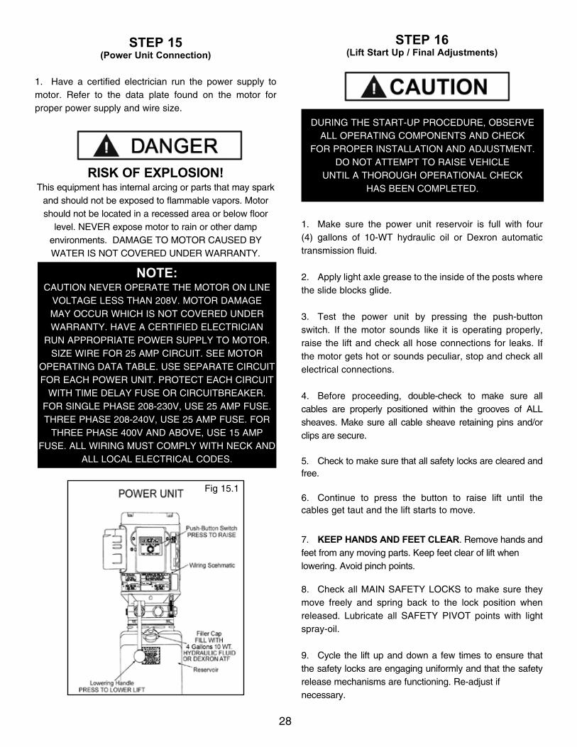
STEP 15(Power Unit Connection)
1. Have a certified electrician run the power supply to motor. Refer to the data plate found on the motor for proper power supply and wire size.
RISK OF EXPLOSION!This equipment has internal arcing or parts that may spark
and should not be exposed to flammable vapors. Motor should not be located in a recessed area or below floor
level. NEVER expose motor to rain or other damp environments. DAMAGE TO MOTOR CAUSED BY WATER IS NOT COVERED UNDER WARRANTY.
STEP 16(Lift Start Up / Final Adjustments)
1. Make sure the power unit reservoir is full with four (4) gallons of 10-WT hydraulic oil or Dexron automatic transmission fluid.
2. Apply light axle grease to the inside of the posts where the slide blocks glide.
3. Test the power unit by pressing the push-button switch. If the motor sounds like it is operating properly, raise the lift and check all hose connections for leaks. If the motor gets hot or sounds peculiar, stop and check all electrical connections.
4. Before proceeding, double-check to make sure all cables are properly positioned within the grooves of ALL sheaves. Make sure all cable sheave retaining pins and/or clips are secure.
5. Check to make sure that all safety locks are cleared and free.
6. Continue to press the button to raise lift until the cables get taut and the lift starts to move.
7. KEEP HANDS AND FEET CLEAR. Remove hands and feet from any moving parts. Keep feet clear of lift when lowering. Avoid pinch points.
8. Check all MAIN SAFETY LOCKS to make sure they move freely and spring back to the lock position when released. Lubricate all SAFETY PIVOT points with light spray-oil.
9. Cycle the lift up and down a few times to ensure that the safety locks are engaging uniformly and that the safety release mechanisms are functioning. Re-adjust if necessary.
NOTE:CAUTION NEVER OPERATE THE MOTOR ON LINE
VOLTAGE LESS THAN 208V. MOTOR DAMAGE MAY OCCUR WHICH IS NOT COVERED UNDER WARRANTY. HAVE A CERTIFIED ELECTRICIAN
RUN APPROPRIATE POWER SUPPLY TO MOTOR. SIZE WIRE FOR 25 AMP CIRCUIT. SEE MOTOR
OPERATING DATA TABLE. USE SEPARATE CIRCUIT FOR EACH POWER UNIT. PROTECT EACH CIRCUIT
WITH TIME DELAY FUSE OR CIRCUITBREAKER. FOR SINGLE PHASE 208-230V, USE 25 AMP FUSE.THREE PHASE 208-240V, USE 25 AMP FUSE. FOR
THREE PHASE 400V AND ABOVE, USE 15 AMP FUSE. ALL WIRING MUST COMPLY WITH NECK AND
ALL LOCAL ELECTRICAL CODES.
Fig 15.1
DURING THE START-UP PROCEDURE, OBSERVE ALL OPERATING COMPONENTS AND CHECK
FOR PROPER INSTALLATION AND ADJUSTMENT. DO NOT ATTEMPT TO RAISE VEHICLE
UNTIL A THOROUGH OPERATIONAL CHECK HAS BEEN COMPLETED.

2929
POST-INSTALLATION CHECK-OFF
n Columns properly shimmed and stable
n Anchor Bolts tightened
n Pivot / Sheave Pins properly attached
n Electric power supply confirmed
n Cables adjusted properly
n Safety Locks functioning properly
n Check for hydraulic leaks
n Oil leveln Lubrication of critical components
n Check for overhead obstructions
n All Screws, Bolts, and Pins securely fastened
n Surrounding area cleann Operation, Maintenance and Safety Manuals on site.n Perform an Operational Test with a typical vehicle
STEP 17(Lubrication)
1. After installation and start up has been completed, lubricate lift components as described below.(See Fig. 17.1)
STEP 18(Bleeding)
1. After electrical power is connected and oil reservoir is full, press button to raise lift.
2. Continue raising until lift cylinders fully extend to full height. DO NOT continue pressing button after lift reach-es full height. Damage to motor can occur if continued.
3. Lower the lift only HALF WAY by pressing the SAFETY RELEASE handle inward then pressing in the DOWN lever on the power unit.
4. With the lift at half height, slowly loosen the BLEED SCREWS located at the top of each cylinder to bleed trapped air. DO NOT completely remove bleed screws. Re-tighten after trapped air has escaped. (See Fig. 18.1)
5. Lower the lift completely by pressing the SAFETY RELEASE handle inward then pressing the DOWN lever on power unit. Wait five minutes and repeat bleeding process one additional time.
NOTE:There will be initial stretching of the cables and/or with increased loads. Adjust the cables as outlined above a week after first use, then every three to six months thereafter depending on usage and/or to compensate
for stretch.
Fig. 17.1
Cylinder Bleed Screw
DO NOT completely
remove Bleed Screw. One full turn should purge trapped air.
Fig. 18.1
THE LIFT WILL MOVE DOWN WHEN BLEEDING MAKE SURE ALL EQUIPMENT, PERSONNEL,
HANDS AND FEET ARE CLEAR BEFORE BLEEDING

3030
OPTIONAL EQUIPMENT INSTALLATION

31
OPTIONAL AND STANDARD ACCESSORIES
Optional Equipment available through your Authorized BendPak Dealer.
Telescoping Screw Pad
Frame Cradle Pad

32
If the lift was provided with Lift Arm Foot Guards, install the shorter Foot Guard on the shorter Arm Assembly and the longer Foot Guard on the longer Arm Assembly.
To install firmly squeeze the ends of the Foot Guard inwards and insert the ends underneath the bent ends of the arm support. Release to allow the Foot Guard to spring into place. Check to be sure that Foot Guard is firmly in place.
Repeat this step for each Arm Assembly Foot Guard.
Optional Equipment available through your Authorized BendPak Dealer.
Arm Support

33
STEP 19(Operation Instructions)
OWNER/EMPLOYER RESPONSIBILITIES
The Owner/Employer:
• Shall ensure that lift operators are qualified and that they are trained in the safe use and operation of the lift using the manufacturer’s operating instructions; ALI/SM01-1, ALI Lifting it Right safety manual; ALI/ST-90 ALI Safety Tips card; ANSI/ALI ALOIM-2000, American National Standard for Automotive Lifts-Safety Requirements for Operation, Inspection and Maintenance; ALI/WL Series, ALI Uniform Warning Label Decals/Placards; and in the case of frame engaging lifts, ALI/LP-GUIDE, Vehicle Lifting Points/Quick Reference Guide for Frame Engaging Lifts.
• Shall establish procedures to periodically inspect the lift in accordance with the lift manufacturer’s instructions or ANSI/ALI ALOIM-2000, American National Standard for Automotive Lifts-Safety Requirements for Operation, Inspection and Maintenance; and The Employer shall ensure that lift inspectors are qualified and that they are adequately trained in the inspection of the lift.
• Shall establish procedures to periodically maintain the lift in accordance with the lift manufacturer’s instructions or ANSI/ALI ALOIM-2000, American National Standard for Automotive Lifts-Safety Requirements for Operation, Inspection and Maintenance; and The Employer shall ensure that lift maintenance personnel are qualified and that they are adequately trained in the maintenance of the lift.• Shall maintain the periodic inspection and maintenance records recommended by the manufacturer or ANSI/ALI ALOIM-2000, American National Standard for Automotive Lifts-Safety Requirements for Operation, Inspection and Maintenance.
• Shall display the lift manufacturer’s operating instructions; ALI/SM 93-1, ALI Lifting It Right safety manual; ALI/ST-90 ALI Safety Tips card; ANSI/ALI AL-OIM-2000, American National Standard for Automotive Lifts-Safety Requirements for Operation, Inspection and Maintenance; and in the case of frame engaging lifts, ALI/LP-GUIDE, Vehicle Lifting Points/Quick Reference Guide for Frame Engaging Lifts; in a conspicuous location in the lift area convenient to the operator.
• Shall provide necessary lockout/tagout means for energy sources per ANSI Z244.1-1982 (R1993), Safety Require-ments for the Lockout/Tagout of Energy Sources, before beginning any lift repairs.
• Shall not modify the lift in any manner without the prior written consent of the manufacturer.
• DAILY inspect your lift. Never operate if it malfunctions or if it has broken or damaged parts. Use only qualified lift service personnel and genuine BendPak parts to make repairs.
• THOROUGHLY train all employees in use and care of lift, using manufacturer’s instructions and “Lifting It Right” and “Safety Tips” supplied with the lift.
• NEVER allow unauthorized or untrained persons to position vehicle or operate lift.
• PROHIBIT unauthorized persons from being in shop area while lift is in use.
• DO NOT permit anyone on lift or inside vehicle when it is either being raised or lowered.
• ALWAYS keep area around lift free of tools, debris, grease and oil.
• NEVER overload lift. Capacity of lift is shown on nameplate affixed to the lift.
• DO NOT stand in front of the vehicle while it is being positioned in lift bay.
• DO NOT hit or run over lift arms or adapters. This could damage lift or vehicle. Before driving vehicle into lift bay, position arms and adapters to provide unobstructed entrance onto lift.
LIFT OPERATION SAFETY

34
LIFT OPERATION SAFETY (CONT’D)• ALWAYS load vehicle on lift carefully. Position the lift adapters to contact at the vehicle manufacturer’s recom-mended lift points. Raise lift until adapters contact vehicle. Check adapters for secure contact with vehicle. Raise lift to desired working height. (See Fig.19.1)
• DO NOT block open or override self-closing lift controls; they are designed to return to the “Off” or Neutral position when released.
• DO NOT remove or disable arm restraints.
• ALWAYS remain clear of lift when raising or lowering vehicles.
• ALWAYS use safety stands when removing or installing heavy components.
• DO NOT go under raised vehicle if safety locks are not engaged.
• NEVER LEAVE LIFT IN ELEVATED CONDITION unless all Safety Locks are engaged.
• AVOID excessive rocking of vehicle while on lift.
• ALWAYS CLEAR AREA if vehicle is in danger of falling.
• ALWAYS REMOVE tool trays, stands, etc. before lowering lift.
• ALWAYS RELEASE safety locks before attempting to lower lift.
• ALWAYS POSITION the lift arms and adapters to provide an unobstructed exit before removing vehicle from lift area.
TO RAISE THE LIFT1. Before Loading: Lift must be fully lowered and service bay clear of all personnel before the vehicle is brought on lift with the swing arms set to the full drive-thru position.
2. Loading: Swing arms under vehicle and position adapters at vehicle manufacturer’s recommended lift points. Use height extenders or optional frame-cradle adapters when necessary to ensure good contact.(See Fig 19.2 - 19.3)
3. Some vehicles may have the manufacturer's Service Garage Lift Point locations identified by triangle shape marks on the undercarriage (reference ANSI/SAE J2184-1992). Also, there may be a label located on the right front door jamb area showing specific vehicle lift points.
VISUALLY CONFIRM THAT ALL PRIMARY SAFETY LOCKS ARE ENGAGED BEFORE ENTERING WORK AREA. SUSPENSION
COMPONENTS USED ON THIS LIFT ARE INTENDED TO RAISE AND LOWER LIFT ONLY
AND ARE NOT MEANT TO BE LOAD HOLDING DEVICES. REMAIN CLEAR OF
ELEVATED LIFT UNLESS VISUAL CONFIRMATION IS MADE THAT ALL PRIMARY
SAFETY LOCKS ARE FULLY ENGAGED AND THE LIFT IS LOWERED ONTO THE SAFETY LOCKS,
REFER TO INSTALLATION/OPERATION MANUAL FOR PROPER SAFETY LOCK PROCEDURES
AND/OR FURTHER INSTRUCTION.
Fig. 19.1
WHEN LOWERING THE LIFT PAY CAREFUL ATTENTION THAT ALL PERSONNEL AND
OBJECTS ARE KEPT CLEAR. ALWAYS KEEP A VISUAL LINE OF SITE ON THE LIFT
AT ALL TIMES. ALWAYS MAKE SURE THAT ALL LOCKS ARE DISENGAGED. IF ONE OF THE
LOCKS INADVERTENTLY LOCKS UPON DESCENT THE VEHICLE MAY DISMOUNT CAUSING
PERSONAL INJURY OR DEATH.
TO AVOID PERSONAL INJURY AND/OR PROPERTY DAMAGE, PERMIT ONLY TRAINED PERSONNEL TO
OPERATE LIFT. AFTER REVIEWING THESE INSTRUCTIONS, PRACTICE USING LIFT CONTROLS
BY RUNNING THE LIFT THROUGH A FEW UNLOADED CYCLES BEFORE LOADING VEHICLE ON LIFT.
ALWAYS LIFT THE VEHICLE USING ALL FOUR ADAPTERS. NEVER RAISE JUST ONE END,
ONE CORNER, OR ONE SIDE OF VEHICLE.

35
LIFT OPERATION SAFETY (CONT’D)
4. Position vehicle for proper weight distribution arms under vehicle to allow adapters to contact at the manufacturer’s recommended pick up points.
5. If the specific vehicle lift points are not identified, refer to the VEHICLE CENTER OF BALANCE instructions found on our website at:
http://www.bendpak.com/support/balancing-safety/
6. Push the RAISE button or rotate the control switch on the power unit.
7. Stop before making contact with vehicle. Check arm restraint pins for engagement. If required, slightly move arm to allow restraint gear and pawl to mesh. DO NOT hammer arm restraint pin down as this will damage the restraint gear teeth.
8. Raise vehicle until tires clear the floor.
9. Stop and check adapters for secure contact at vehicle manufacturer’s recommended lift points.
MANY SPECIALTY OR MODIFIED VEHICLES CANNOT BE RAISED ON A TWO-POST FRAME
ENGAGING LIFT. CONTACT VEHICLE MANUFACTURER FOR RAISING
OR JACKING DETAILS.
Fig. 19.2 TYPICAL LIFTING POINTS
NOTE: ALLOW (2) SECONDS BETWEEN MOTOR STARTS.
FAILURE TO COMPLY MAY CAUSE MOTOR BURNOUT.
Fig. 19.3

36
10. Continue to raise to desired height only if vehicle is secure on lift.
11. DO NOT go near or under a raised vehicle if all four adapters are not in secure contact with vehicle at vehicle manufacturer’s recommended lift points.
12. Repeat entire loading and raising procedures if required.
13. Lower lift onto safety locks.• DO NOT enter work area or go under vehicle if safety locks are not engaged.
• CLEAR AREA if vehicle is in danger of falling.
• DO NOT position yourself between a wall and the lift. If the vehicle falls in that direction, you may be severely injured or killed.
• Before attempting to lift pickup trucks or other truck frame vehicles, be sure that:
t Vehicle frame is strong enough to support its weight and has not been weakened by modification or corrosion. t Vehicle individual axle weight does not exceed one-half lift capacity. t Adapters are in secure contact with frame at vehicle manufacturers recommended lift points. t Vehicle is stable on lift and the center of gravity is NOT off balance. t The overhead switch bar will contact the highest point on the vehicle.
WHILE USING LIFT
• Avoid excessive rocking of vehicle while on lift.
• Always use safety stands as needed or when removing or installing heavy components.
TO LOWER THE LIFT1. Remove all tools or other objects from the lift area.
2. Raise lift off safety locks.
3. Push safety lock release handle fully and hold.
4. Push LOWERING valve handle to lower. Note: Both SAFETY LOCK release and LOWERING valve handles must be held down simultaneously to lower lift. Do not override self-closing lift controls.
5. Remain clear of lift when lowering vehicle. Observe pinch point warning decals.
6. Remove adapters from under vehicle and swing arms to full drive-thru position before moving vehicle.
7. If lift is not operating properly, DO NOT use until adjustment or repairs are made by qualified lift service personnel.
MAINTENANCE INSTRUCTIONS• Always keep bolts tight. Check periodically.
• Always keep lift components clean.
• Always if oil leakage is observed, call local service representative.• Always call local service representative if electrical problems develop.
VISUALLY CONFIRM THAT ALL PRIMARY SAFETY LOCKS ARE ENGAGED BEFORE ENTERING WORK AREA. SUSPENSION COMPONENTS USED ON THIS
LIFT ARE INTENDED TO RAISE AND LOWER LIFT ONLY AND ARE NOT MEANT TO BE LOAD HOLDING
DEVICES. REMAIN CLEAR OF ELEVATED LIFT UNLESS VISUAL CONFIRMATION
IS MADE THAT ALL PRIMARY SAFETY LOCKS ARE FULLY ENGAGED AND THE LIFT IS LOWERED ONTO
THE SAFETY LOCKS, REFER TO INSTALLATION /OPERATION MANUAL FOR PROPER SAFETY.
LIFT OPERATION SAFETY (CONT’D)
WHEN LOWERING THE LIFT PAY CAREFUL ATTENTION THAT ALL PERSONNEL AND
OBJECTS ARE KEPT CLEAR. ALWAYS KEEP A VISUAL LINE OF SITE ON THE LIFT AT ALL TIMES.
ALWAYS MAKE SURE THAT ALL LOCKS ARE DISENGAGED. IF ONE OF THE LOCKS
INADVERTENTLY LOCKS ON DESCENT THE LIFT AND/OR VEHICLE MAY DISRUPT CAUSING
PERSONAL INJURY OR DEATH.
IF YOU ARE NOT COMPLETELY FAMILIAR WITH AUTOMOTIVE LIFT MAINTENANCE PROCEDURES; STOP AND CONTACT THE MANUFACTURER FOR INSTRUCTIONS. TO AVOID PERSONAL INJURY,
PERMIT ONLY QUALIFIED PERSONNEL TO PERFORM MAINTENANCE ON
THIS EQUIPMENT.

37
• Always replace ALL FAULTY PARTS before lift is put back into operation.
• Daily: Make a visual inspection of ALL MOVING PARTS and check for excessive signs of wear.
• Daily: Check safety locks to ensure they are in good operating condition.
• Daily: Check cables and sheaves for wear. Replace worn parts as required with genuine BendPak parts.
• Daily: Inspect adapters for damage or excessive wear. Replace as required with genuine BendPak parts.
• Weekly: Lubricate all sheave and rollers with general purpose oil.
• Weekly: Check all cable connections, bolts and pins to ensure proper mounting.
• Monthly: Check equalizer cable tension. Adjust per lift installation instructions.
• Monthly: Lubricate locking latch shafts. Push latch handle several times for oil to penetrate pivot points.
• Every 3 Months: Check anchor bolt torque. Anchors should be torqued to 90 ft/lbs.
• Semi-Annually: Check fluid level of lift power unit and refill if required per lift installation instructions.
• Replace all caution, warning or safety related decals on the lift if unable to read or missing. Reorder labels from BendPak.
• Refer to ANSI/ALI ALOIM booklet for periodic inspection checklist and maintenance log sheet.
LIFT OPERATION SAFETY (CONT’D)
Before lifting the vehicle, make sure it is neither front nor rear heavy. See image below. Center of balance should be midway between adapters.

38
TO RAISE LIFT
t Read operating and Safety manuals before using lift.t Always lift a vehicle according to the manufacturers recommended lifting points.t Position vehicle between columns.t Adjust swing arms so that the vehicle is positioned with the center of gravity midway between pads.t Use truck adapters as needed. Never exceed 9” of Pad height.t NEVER use lift pad assemblies without rubber slip over pads in place.t Raise the vehicle by depressing button until the vehicle just lifts off the ground. Re-check to make sure the vehicle is secure and all locking pins are lock in place.t Raise vehicle to desired height. Lower vehicle onto nearest safety,t Always ensure safeties are engaged before any attempt is made to work on or near vehicle.
TO LOWER THE LIFTt First raise the lift clear to the safeties.t Release safeties by pulling on the safety handle.t Be sure tool trays, stands or personnel are cleared from under the vehicle.t Lower vehicle by activating lowering handle on power unit.t Before removing vehicle from lift; position lift arms and supports to provide an unobstructed exit.t NEVER, drive over lift arms.
REQUIRED MONTHLY MAINTENANCEt Check all arm adjusting locks for proper operation.t Check all cables connections, bolts and pins to ensure proper mounting and torque.t Visually inspect safeties for proper operation.t Lubricate columns with grease.t Inspect all anchors bolts and retighten if necessary.t Check all columns for squareness and plumb.t Inspect all pivot arms pins making sure they are properly secure.t Check equalizer cable tension, and adjust if necessary.t If lift is equipped with over head cut-off switch, check for proper operation.
1. WARNING!: If cement anchor bolts are loose or any component of the lift is found to be defective, DO NOT USE THE LIFT!!2. Never operate the lift with any person or equipment below the vehicle.3. Never exceed the rated lift capacity.4. Always ensure the safeties are engaged before any attempt is made to work on or near the vehicle.5. Never leave lift in elevated position unless the safeties are engaged.6. Do not permit electric motor to get wet! Motor damage caused by dampness is not covered under warranty.
NEVER LIFT ANY VEHICLE IN ANY MANNER WITH LESS THAN ALL FOUR (4) ARMS. RATED CAPACITY OF EACH LIFT ARM IS NO GREATER THAN ONE FOURTH
(1/4) OF THE OVERALL LIFT CAPACITY.
38

3939
WIRE ROPE INSPECTION AND MAINTENANCE
t Lifting cables should be replaced every three - five years or when visible signs of damage are apparent. DO NOT USE LIFT WITH DEFECTIVE / WORN CABLES.
t Lifting cables should be maintained in a well-lubricated condition at all times. Wire rope is only fully protected when each wire strand is lubricated both internal and external. Excessive wear will shorten the life of the wire rope. The factory suggested wire rope lubricant that penetrates to the core of the rope and provides long-term lubrication between each individual strand is 90-WT gear oil or ALMASOL® Wire Rope Lubricant. In order to make sure that the inner layers of the rope remain well lubricated, lubrication should be carried out at intervals not exceeding three months during operation. t All sheaves and guide rollers in contact with the moving rope should be given regular visual checks for surface wear and lubricated to make sure that they run freely. This operation should be carried out at appropriate intervals generally not exceeding three months during operation. For all sheave axles, the factory recommends standard wheel bearing grease. For all sheaves and/or guide rollers, the factory recommends 90-WT gear oil or similar heavy lubricant applied by any method including pump / spray dispensing, brush, hand and/or swabbing.
.HOW OFTEN TO INSPECT
t Lifting cables should be visually inspected at least once each day when in use, as suggested by American Petroleum Institute (API) RP54 guidelines.
t Any lifting cables that have met the criteria for removal must be immediately replaced.
WHEN TO REPLACE LIFTING CABLES DUE TO BROKEN WIRESt Lifting cables should be removed from service when you see six randomly distributed broken wires within any one lay length, or three broken wires in one strand within one lay length.
OTHER REASONS TO REPLACE LIFTING CABLESt Corrosion that pits the wires and/or connectors.t Evidence of kinking, crushing, cutting, bird-caging or a popped core.t Wear that exceeds 10% of a wire’s original diameter.t Evidence of heat damage.
HOW TO FIND BROKEN WIRESt The first step is to relax your rope to a stationary position and move the pick-up points off the sheaves. Clean the surface of the rope with a cloth — a wire brush, if necessary — so you can see any breaks.
t Flex the rope to expose any broken wires hidden in the valleys between the strands. t Visually check for any broken wires. One way to check for crown breaks is to run a cloth along the rope to check for possible snags. t With an awl, probe between wires and strands and lift any wires that appear loose. Evidence of internal broken wires may require a more extensive rope examination.
CENTER WIRE
WIRE ROPE
STRANDONE LAY LENGTH
WIRECORE

40

4141

4242
Safe Lift OperationAutomotive and truck lifts are critical to the operation and profitability of your business. The safe use of this and other lifts in your shop is critical in preventing employee injuries and damage to customer’s vehicles. By operating lifts safely you can ensure that your shop is profitable, productive and safe.Safe operation of automotive lifts requires that only trained employees should be allowed to use the lift.
TRAINING SHOULD INCLUDE, BUT NOT LIMITED TO:t Proper positioning of the vehicle on the lift arms. (See manufacturers minimize wheel base loading requirements.)
t Use of the operating controls.
t Understanding the lift capacity.
t Proper use of jack stands or other load supporting devices.
t Proper use, understanding and visual identification of safety lock devices and their operation.
t Reviewing the safety rules.
t Proper housekeeping procedures (lift area should be free of grease, oil, tools, equipment, trash, and other debris).
t A daily inspection of the lift should be completed prior to its use. Safety devices, operating controls, lift arms and other critical parts should be inspected prior to using the lift.
t All maintenance and repairs of the lift should be completed by following the manufacturer’s requirements. Lift repair parts should meet or exceed OEM specifications. Repairs should only be completed by a qualified lift technician.
t The vehicle manufacturer’s recommendations should be used for spotting and lifting the vehicle.
LIFT OPERATION / SAFETY
t It is important that you know the load limit. Be careful that you do not overload the lift . If you are unsure what the load limit is, check the data plate found on one of the lift columns or contact the manufacturer.
t The center of gravity should be followed closely to what the manufacturer recommends.
t Always make sure you have proper overhead clearance. Additionally, check that attachments, ( vehicle signs, campers, antennas, etc.) are not in the way.
t Be sure that prior to the vehicle being raised, the doors, trunk, and hood are closed securely.
t Prior to being raised, make sure there is no one standing closer than six feet from the lift.
t After positioning the vehicle on the lift runways, set the emergency brake, make sure the ignition is off, the doors are closed, overhead obstructions are cleared, and the transmission is in neutral.
t Double check that the automatic chock devices are in position and then when the lift is raised, observe the chocks. t Put pads or adapters in the right position under the contact points that have been recommended.
t The lift should be raised just until the vehicle’s wheels are about one foot off the ground. If contact with the vehicle is uneven or it appears that the vehicle is not sitting secure, carefully lower the lift and readjust.
t Always consider potential problems that might cause a vehicle to slip, i.e., heavy cargo, undercoating, etc.
t Pay attention when walking under a vehicle that is up on the hydraulic lift.

43
t DO NOT leave the controls while the lift is still in motion.
t DO NOT stand directly in front of the vehicle or in the bay when vehicle is being loaded or driven into position.
t DO NOT go near vehicle or attempt to work on the vehicle when being raised or lowered.
t REMAIN CLEAR of lift when raising or lowering vehicle.
t DO NOT rock the vehicle while on the lift or remove any heavy component from vehicle that may cause excessive weight shift.
t DO NOT lower the vehicle until people, materials, and tools are clear
t ALWAYS ENSURE that the safeties are engaged and lowered on to the safety ladders before any attempt is made to work on or near vehicle.
t Some vehicle maintenance and repair activities may cause the vehicle to shift. Follow the manufacturer’s guidelines when performing these operations. The use of jack stands or alternate lift points may be required when completing some repairs.
t READ AND UNDERSTAND all safety warning procedures before operating lift.
t KEEP HANDS AND FEET CLEAR. Remove hands and feet from any moving parts. Keep feet clear of lift when lowering. Avoid pinch points.
t ONLY TRAINED OPERATORS should operate this lift. All non-trained personnel should be kept away from work area. Never let non-trained personnel come in contact with, or operate lift.
t USE LIFT CORRECTLY. Use lift in the proper manner. Never use lifting adapters other than what is approved by the manufacturer.
t DO NOT override self-closing lift controls.
t CLEAR AREA if vehicle is on danger of falling.
t STAY ALERT. Watch what you are doing. Use common sense. Be aware.
t CHECK FOR DAMAGED PARTS. Check for alignment of moving parts, breakage of parts or any condition that may affect its operation. Do not use lift if any component is broken or damaged.
t NEVER remove safety related components from the lift. Do not use lift if safety related components are damaged or missing.
t When the lift is being lowered, make sure everyone is standing at least six feet away.
t Be sure there are no jacks, tools, equipment, left under the lift before lowering.
t Always lower the vehicle down slowly and smoothly.
43

4444
LIFT WILL NOT RAISE
POSSIBLE CAUSE1. Air in oil, (1,2,8,13)2. Cylinder binding, (9)3. Cylinder leaks internally, (9)4. Motor run backward under pressure, (11)5. Lowering valve leaks, (3,4,6,10,11)6. Motor runs backwards, (7,14,11)7. Pump damaged, (10,11)8. Pump won’t prime, (1,8,13,14,3,12,10,11)9. Relief valve leaks, (10,11)10. Voltage to motor incorrect, (7,14,11)
REMEDY INSTRUCTION1. Check for proper oil level. . . . . . . . . . . . . . . . . . . . . . . . . . The oil level should be up to the bleed screw in the reservoir with the lift all the way down.
2. Bleed cylinders. . . . . . . . . . . . . . . . . . . . . . . . . . . . . . . . . . See Installation Manual
3. Flush- Release valve to get rid of. . . . . . . . . . . . . . . . . . . . . Hold release handle down and start unit allowing possible contamination it to run for 15 seconds.
4. Dirty oil. . . . . . . . . . . . . . . . . . . . . . . . . . . . .. . . . . . . . . . . . Replace oil with clean Dexron ATF.
5. Tighten all fasteners. . . . . . . . . . . . . . . . . . . . . . . . . . . . . . . Tighten fasteners to recommended torques.
6. Check for free movement of release. . . . . . . . . . . . . . . . . . . If handle does not move freely, replace bracket or handle assembly. 7. Check motor is wired correctly. . . . . . . . . . . . . . . . . . . . . . . Compare wiring of motor to electrical diagram on drawing.
8. Oil seal damaged or cocked . . . . . . . . . . . . . . . . . . . . . . . . Replace oil seal around pump shaft.
9. See Installation Manual . . . . . . . . . . . . . . . . . . . . . . . . . . . . Consult Lift Manufacturer.
10. Replace with new part . . . . . . . . . . . . . . . . . . . . . . . . . . . . . Replace with new part.
11. Return unit for repair . . . . . . . . . . . . . . . . . . . . . . . . . . . . . . Return unit for repair.
12. Check pump-mounting bolts . . . . . . . . . . . . . . . . . . . . . . . . Bolts should be 15 to 18 ft. lbs.
13. Inlet screen clogged . . . . . . . . . . . . . . . . . . . . . . . . . . . . . . Clean inlet screen or replace.
14. Check wall outlet voltages and wiring . . . . . . . . . . . . . . . . . Make sure unit and wall outlet are wired properly.

45
MOTOR WILL NOT RUN
POSSIBLE CAUSE1. Fuse blown, (5,2,1,3,4)2. Limit switch burned out, (1,2,3,4)3. Microswitch burned out, (1,2,3,4)4. Motor burned out, (1,2,3,4,6)5. Voltage to motor incorrect, (2,1,8)
REMEDY INSTRUCTIONS1. Check for correct voltage . . . . . . . . . . . . . . . . . . Compare supply voltage with voltage on motor name tag. Check that the wire is sized correctly. N.E.C table 310-12 requires AWG 10 for 25 amps. 2. Check motor is wired correctly . . . . . . . . . . . . . . . . Compare wiring of motor to electrical diagram on drawing.
3. Don’t use extension cords . . . . . . . . . . . . . . . . . . . . . . According to N.E.C. : “ The size of the conductors should be such that the voltage drop would not exceed 3% to the farthest outlet for power. *Do not run motor at 115 VAC - damage to the motor will occur.
4. Replace with new part . . . . . . . . . . . . . . . . . . . . . . .. Replace with new part.
5. Reset circuit breaker/fuse . . . . . . . . . . . . . . . . . . . . . Reset circuit breaker/fuse.
6. Return unit for repair . . . . . . . . . . . . . . . . . . . . . . . . . . . . Return unit for repair.
7. See Installation Manual . . . . . . . . . . . . . . . . . . . . . . . . See Installation Manual.
8. Check wall outlet voltage and wiring . . . . . . . . . . . . . . Make sure unit and wall outlet is wired properly. Motor must run at 208/230 VAC.
LIFT LOWERS SLOWLY OR NOT AT ALL
POSSIBLE CAUSE1. Cylinders binding, (1)2. Release valve clogged, (5,4,2,3)3. Pressure fitting too long, (6)
REMEDY INSTRUCTIONS1. See Installation Manual . . . . . . . . . . . . . . . . . . . . Consult Lift Manufacturer.
2. Replace with new part . . . . . . . . . . . . . . . . . . . . . . Replace with new part.
3. Return for repair . . . . . . . . . . . . . . . . . . . . . . . . . . Return for repair.
4. Check oil. . . . . . . . . . . . . . . . . . . . . Use clean 10-WT hydraulic oil or Dexron automatic transmission fluid only. If ATF is contaminated, replace with clean ATF and clean entire system.
5. Clean release valve . . . . . . . . . . . . . . . . . . . . . . . . . Wash release valve in solvent and blow out with air.
6. Replace fitting with short thread lead . . . . . . . . . . . . . . Replace fitting with short thread lead.
45

4646
WILL NOT RAISE LOADED LIFT
POSSIBLE CAUSE1. Air in oil, (1,2,3,4)2. Cylinder binding, (5)3. Cylinder leaks internally, (5)4. Lift overloaded, (6,5)5. Lowering valve leaks, (7,8,1,5,9)6. Motor runs backwards, (10,12,9)7. Pump damaged, (5,9)8. Pump won’t prime, (1,2,3,4,5,11,9)9. Relief valve leaks, (8,5,9)10. Voltage to motor incorrect, (10,12,5)
REMEDY INSTRUCTIONS1. Check oil level . . . . . . . . . . . . . . . . . . . . . . . . . . . . . . . . . . The oil level should be up to the bleed screw in the reservoir with the lift all the way down.
2. Check/Tighten inlet tubes . . . . . . . . . . . . . . . . . . . . . . . . . . Replace inlet hose assembly.
3. Oil seal damaged or cocked . . . . . . . . . . . . . . . . . . . . . . . . Replace oil seal and install.
4. Bleed cylinders . . . . . . . . . . . . . . . . . . . . . . . . . . . . . . . . . . See Installation Manual.
5. See Installation Manual . . . . . . . . . . . . . . . . . . . . . . . . . . . . Consult Lift Manufacturer.
6. Check vehicle weight . . . . . . . . . . . . . . . . . . . . . . . . . . . . . Compare weight of vehicle to weight limit of the lift.
7. Flush release valve . . . . . . . . . . . . . . . . . . . . . . . . . . . . . Hold release handle down and start unit allowing it to run for 15 seconds.
8. Replace with new part . . . . . . . . . . . . . . . . . . . . . . . . . . . . . Replace with new part.
9. Return unit for repair . . . . . . . . . . . . . . . . . . . . . . . . . . . . . . Return unit for repair.
10. Check motor is wired correctly . . . . . . . . . . . . . . . . . . . . . . . Compare wiring of motor to electrical diagram on power unit drawing.
11. Inlet screen clogged . . . . . . . . . . . . . . . . . . . . . . . . . . . . . . Clean inlet screen or replace.
12. Check wall outlet voltage and wiring . . . . . . . . . . . . . . . . . . Make sure unit and wall outlet is wired properly.
IMPORTANTIf vehicle becomes stranded in the air, follow all operation instructions as shown on pages 31 - 36. If after observing that all mechanical locks are released and the lift still fails move following all standard operating procedures, immediately
stop using the lift and contact factory or factory approved service center for further instructions.

47
LIFT WILL NOT STAY UPPOSSIBLE CAUSE1. Air in oil, (1,2,3)2. Check valve leaks, (6)3. Cylinders leak internally, (7)4. Lowering valve leaks, (4,5,1,7,6)5. Leaking fittings, (8)
REMEDY INSTRUCTIONS1. Check oil level . . . . . . . . . . . . . . . . . . . . . . . . . . . . . . . . . . . The oil level should be up to the bleed screw in the reservoir with the lift all the way down.
2. Oil seal damaged and cocked . . . . . . . . . . . . . . . . . . . . . . . . Replace oil seal around pump shaft.
3. Bleed cylinder . . . . . . . . . . . . . . . . . . . . . . . . . . . . . . . . . . . . Refer to Installation Manual.
4. Flush release valve . . . . . . . . . . . . . . . . . . . . . . . . . . . . . . . Hold release handle down and start unit allowing it to run for 15 seconds.
5. Replace with new valve . . . . . . . . . . . . . . . . . . . . . . . . . . . . . Replace with new valve.
6. Return unit for repair . . . . . . . . . . . . . . . . . . . . . . . . . . . . . . Return unit for repair.
7. See Installation Manual . . . . . . . . . . . . . . . . . . . . . . . . . . . . . Consult Lift Manufacturer.
8. Check complete hydraulic system for leaks. . . . . . . . . . . . Tighten all hydraulics fittings and inspects all hoses.
VALUES ARE STATED IN FOOT POUNDS (ft-lb)
SAE 0-1-2 SAE Grade 5 SAE Grade 8 SOCKET HEAD CAP SCREW
CLASS 4.8 CLASS 8.8 CLASS 10.9 CLASS 12.9
Bolt Size (SAE)
Bolt Size (Metric)
1/4-20 M6 x 1.0 6 10 14 13
5/16-18 M8 x 1.25 12 19 29 31.4
3/8-16 M10 x 1.50 20 33 47 62
7/16-14 32 54 78
1/2-13 M12 x 1.75 47 78 119 108
9/16-12 M14 x 2.00 69 114 169 173
5/8-11 M16 x 2.00 96 154 230 269
3/4-10 M18 x 2.50 155 257 380 372
7/8-9 M22 x 2.50 206 382 600 716
3/4 Anchor Bolts 75 MIN 110 MAX
Torque Recommendations

4848

49
DIM
ENSI
ON
S A
RE IN
MM
☺
3
2
1
REV
ISIO
NRE
VD
ESC
RIPT
ION
DA
TEED
ITED
BY
ECO
#U
UPD
ATE
D B
OM
REV
ISIO
NS
12/0
1/20
14TM
0067
3V
UPD
ATE
D B
OM
REV
ISIO
NS
05/1
2/20
15TM
0068
9W
UPD
ATE
D B
OM
REV
ISIO
NS
AN
D N
EXT
ASS
EMBL
IES
12/0
8/20
15TM
0073
8
NEX
T A
SSEM
BLY
5260
563
5260
565
5260
567
5260
569
ITEM
NO
PART
NUM
BER
DES
CRI
PTIO
NQ
TYRE
V1
5215
293
XPR-
12C
PO
WER
SID
E PO
ST A
SSEM
BLY
1V
252
1529
2XP
R-12
C O
FF S
IDE
POST
ASS
EMBL
Y1
V3
5210
031
XPR-
12/1
5/18
C T
OP
TRO
UGH
ASS
EMBL
Y1
K
SHE
ET 1
OF
1
REV
DW
G.
NO
.
ASIZETITLE
:
NA
ME
DA
TE
CHE
CKE
D
DRA
WN
W
1645
LEM
ON
WO
OD
DR.
SAN
TA P
AUL
A, C
A 9
3060
PRO
PRIE
TARY
AN
D C
ON
FIDE
NTIA
LTH
E IN
FORM
ATIO
N C
ON
TAIN
ED IN
THI
S D
RAW
ING
IS
THE
SOLE
PRO
PERT
Y O
F BE
NDP
AK
INC
. AN
Y RE
PRO
DUC
TION
IN P
ART
OR
AS
A W
HOLE
WITH
OUT
TH
E W
RITT
EN P
ERM
ISSI
ON
OF
BEN
DPA
K IN
C. I
S PR
OHI
BITE
D.
NO
TE: U
NLE
SS O
THER
WIS
E SP
ECIF
IED.
TM
5245
138
XPR-
12C
LIF
T SU
PERS
TRUC
TURE
01/2
9/20
10
DO
NO
T SC
ALE
DRA
WIN
G
1:35
SCA
LE:
THIR
D A
NG
LE P
ROJE
CTIO
N
SEE
SHIP
PIN
G IN
STRU
CTIO
NS
FOR
FIN
AL
PAC
KAG
ING
1.

5050
DIM
ENSI
ON
S A
RE IN
MM
☺
3
2
1
REV
ISIO
NRE
VD
ESC
RIPT
ION
DA
TEED
ITED
BY
ECO
#U
UPD
ATE
D B
OM
REV
ISIO
NS
12/0
1/20
14TM
0067
3V
UPD
ATE
D B
OM
REV
ISIO
NS
05/1
4/20
15TM
0068
9W
UPD
ATE
D B
OM
REV
ISIO
NS
AN
D N
EXT
ASS
EMBL
IES
12/0
8/20
15TM
0073
8
NEX
T A
SSEM
BLY
5260
564
5260
571
5260
576
5260
577
ITEM
NO
PART
NUM
BER
DES
CRI
PTIO
NQ
TYRE
V1
5215
218
XPR-
15/1
8C P
OW
ER S
IDE
POST
ASS
EMBL
Y1
V2
5215
216
XPR-
15/1
8C O
FF S
IDE
POST
ASS
EMBL
Y1
V3
5210
031
XPR-
12/1
5/18
C T
OP
TRO
UGH
ASS
EMBL
Y1
K
SHE
ET 1
OF
1
REV
DW
G.
NO
.
ASIZETITLE
:
NA
ME
DA
TE
CHE
CKE
D
DRA
WN
W
1645
LEM
ON
WO
OD
DR.
SAN
TA P
AUL
A, C
A 9
3060
PRO
PRIE
TARY
AN
D C
ON
FIDE
NTIA
LTH
E IN
FORM
ATIO
N C
ON
TAIN
ED IN
THI
S D
RAW
ING
IS
THE
SOLE
PRO
PERT
Y O
F BE
NDP
AK
INC
. AN
Y RE
PRO
DUC
TION
IN P
ART
OR
AS
A W
HOLE
WITH
OUT
TH
E W
RITT
EN P
ERM
ISSI
ON
OF
BEN
DPA
K IN
C. I
S PR
OHI
BITE
D.
NO
TE: U
NLE
SS O
THER
WIS
E SP
ECIF
IED.
TM
5245
139
XPR-
15/1
8C L
IFT
SUPE
RSTR
UCTU
RE
02/0
3/20
10
DO
NO
T SC
ALE
DRA
WIN
G
1:35
SCA
LE:
THIR
D A
NG
LE P
ROJE
CTIO
N
SEE
SHIP
PIN
G IN
STRU
CTIO
NS
FOR
FIN
AL
PAC
KAG
ING
1.

51
DIM
ENSI
ON
S A
RE IN
MM
☺N
EXT
ASS
EMBL
Y52
6056
752
6056
9
ITEM
N
OPA
RT
NUM
BER
DES
CRI
PTIO
NQ
TYRE
V1
5174
518
XPR
CLE
ARF
LOO
R PA
RTS
BAG
1J
257
3660
5XP
R-12
BO
LT O
N A
RM R
ESTR
AIN
T G
EAR
4E
357
4619
2A
RM A
DA
PTER
, MED
IUM
4C
457
4619
3A
RM A
DA
PTER
, LO
NG
4B
552
1000
9XP
R-9D
/10/
12/1
2FD
/15/
18C
OFF
SID
E SA
FETY
CO
VER
1E
656
0016
3XP
R C
LEA
RFLO
OR
POW
ER S
IDE
SAFE
TY C
OV
ER1
E7
5215
701
ROUN
D L
IFT
PAD
AD
APT
ER A
SSEM
BLY
4A
857
1500
3PO
WER
UN
IT V
IBRA
TION
DA
MPE
NER
1B
952
1001
0XP
R O
FF S
IDE
SAFE
TY W
ELD
MEN
T1
E10
5210
007
XPR
POW
ER S
IDE
SAFE
Y A
SSEM
BLY
1F
1155
0534
6XP
R-12
C/F
D L
IFT
HEA
D P
IN W
ELD
MEN
T4
B12
5570
150
XPR-
12C
/15/
18C
HYD
RAUL
IC H
OSE
ASS
Y Ø
6.35
x 9
611m
m
SB1
D13
5570
017
XPR
HYD
RAUL
IC H
OSE
ASS
Y Ø
10 x
121
9mm
SB
1C
1455
7083
2XP
R C
LEA
RFLO
OR
HYD
RAUL
IC H
OSE
ASS
Y Ø
6.35
x
2299
mm
SB
1E
1555
9512
5XP
R-12
C/1
5/18
C Ø
2.4m
m x
890
0 SA
FETY
CA
BLE
1B
1655
9592
2XP
R-12
C/1
5/18
C/
XPR-
12C
-LW
B C
ABL
E A
SSY
Ø12
x
1064
0mm
ST
2A
1755
3501
1N
UT M
22 x
2.5
NL
2-
1855
4534
5W
ASH
ER M
22 x
50m
m F
LAT
2-
1955
4028
1C
RIN
G Ø
38m
m O
D 5
103-
150
4-
2057
4616
6D
OUB
LE T
HREA
DED
RO
D M
10 x
1.5
x 2
952
B21
5525
150
SPD
T M
ICRO
SW
ITCH;
25A
@12
5VA
C1
-22
5520
116
14-4
SJO
UL
62 C
ABL
E 30
0vac
4275
mm
*-
2355
2511
2M
ICRO
SW
ITCH
CO
VER
-5PA
21
-24
5716
634
XPR
MIC
ROSW
ITCH
CO
VER
, PLA
STIC
1A
2552
1570
2C
RAD
LE L
IFT
PAD
LA
RGE
AD
APT
ER A
SSEM
BLY
4B
2655
3030
8A
B 3/
4" x
7"
14-
2755
5011
2FT
G N
PL -0
4 N
PT x
-04
F N
PT2
-28
5900
280
ALI
/LP
FRA
ME
ENG
AG
ING
LIF
TS G
UID
E1
-29
5900
152
ALI
GN
OIM
OPE
RATIO
N IN
SPEC
TION
&
MA
INTE
NA
NC
E1
-30
5900
147
SAFE
TY M
AN
UAL
ALI
/ S
M 9
3-1
1-
3159
0515
1SA
FETY
TIP
S C
ARD
ALI
-ST
901
-32
5900
224
XPR-
12C
-18
INST
ALL
ATIO
N M
AN
UAL
1-
REV
ISIO
NRE
VD
ESC
RIPT
ION
DA
TEED
ITED
BY
ECO
#A
PRO
DUC
TION
REL
EASE
, DER
IVED
FRO
M 5
2500
4112
/15/
2015
TM00
738
SHE
ET 1
OF
2
REV
DW
G.
NO
.
ASIZETITLE
:
NA
ME
DA
TE
CHE
CKE
D
DRA
WN
A
1645
LEM
ON
WO
OD
DR.
SAN
TA P
AUL
A, C
A 9
3060
PRO
PRIE
TARY
AN
D C
ON
FIDE
NTIA
LTH
E IN
FORM
ATIO
N C
ON
TAIN
ED IN
THI
S D
RAW
ING
IS
THE
SOLE
PRO
PERT
Y O
F BE
NDP
AK
INC
. AN
Y RE
PRO
DUC
TION
IN P
ART
OR
AS
A W
HOLE
WITH
OUT
TH
E W
RITT
EN P
ERM
ISSI
ON
OF
BEN
DPA
K IN
C. I
S PR
OHI
BITE
D.
NO
TE: U
NLE
SS O
THER
WIS
E SP
ECIF
IED.
TM
5250
041
XPR-
12C
L/12
CL-
LWB
PART
S BO
X
12/1
5/20
15
DO
NO
T SC
ALE
DRA
WIN
G
1:28
SCA
LE:
THIR
D A
NG
LE P
ROJE
CTIO
N
INSE
RT P
ART
S BA
G IN
TO P
ART
S BO
X FO
R SH
IPM
ENT
1.SE
E SH
IPPI
NG
INST
RUC
TION
S FO
R FI
NA
L PA
CKA
GIN
G2.
THRE
AD
553
5011
ON
TO C
ABL
ES W
ITH 5
5453
45 F
OR
SHIP
MEN
T3.
FOR
5220
116
SPEC
IFIC
ATIO
NS
REFE
R TO
PA
RT S
PEC
IFIC
ATIO
N F
ORM
4.(*
)552
0116
QTY
FO
R RE
FERE
NC
E O
NLY
5.
51
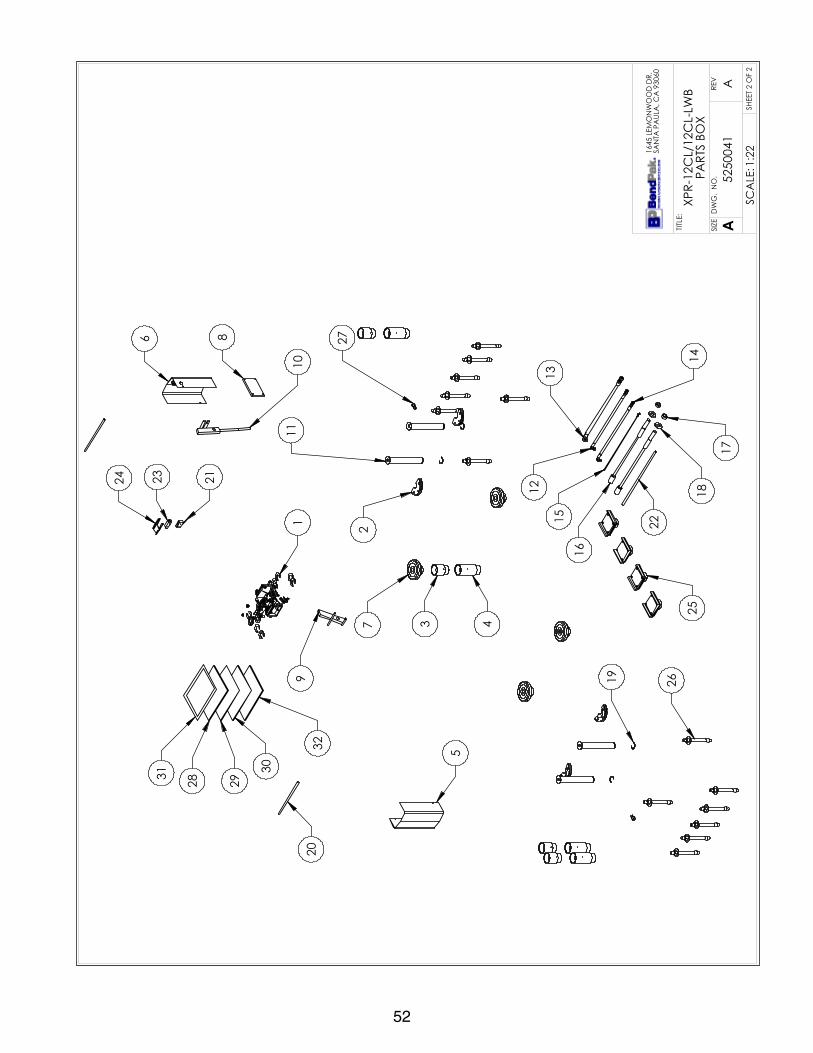
52
10
86
11
7
12
15
17
18
13
14
16
43
5
9 19
20
2
2622
21
32
30
29283123
25
1
24
27
SHE
ET 2
OF
2
REV
DW
G.
NO
.
ASIZETITLE
:
A
1645
LEM
ON
WO
OD
DR.
SAN
TA P
AUL
A, C
A 9
3060
5250
041
XPR-
12C
L/12
CL-
LWB
PART
S BO
X
1:22
SCA
LE:

53
DIM
ENSI
ON
S A
RE IN
MM
☺N
EXT
ASS
EMBL
Y52
6057
1
ITEM
N
OPA
RT
NUM
BER
DES
CRI
PTIO
NQ
TYRE
V1
5174
518
XPR
CLE
ARF
LOO
R PA
RTS
BAG
1J
257
3660
6XP
R-15
/18
BOLT
ON
ARM
RES
TRA
INT
GEA
R4
F3
5746
192
ARM
AD
APT
ER, M
EDIU
M4
C4
5746
193
ARM
AD
APT
ER, L
ON
G4
B5
5210
009
XPR-
9D/1
0/12
/12F
D/1
5/18
C O
FF S
IDE
SAFE
TY C
OV
ER1
E6
5600
163
XPR
CLE
ARF
LOO
R PO
WER
SID
E SA
FETY
CO
VER
1E
752
1570
1RO
UND
LIF
T PA
D A
DA
PTER
ASS
EMBL
Y4
A8
5715
003
POW
ER U
NIT
VIB
RATIO
N D
AM
PEN
ER1
B9
5210
010
XPR
OFF
SID
E SA
FETY
WEL
DM
ENT
1E
1052
1000
7XP
R PO
WER
SID
E SA
FEY
ASS
EMBL
Y1
F11
5600
349
XPR-
15/1
8C L
IFT
HEA
D P
IN W
ELD
MEN
T4
C12
5570
150
XPR-
12C
/15/
18C
HYD
RAUL
IC H
OSE
ASS
Y Ø
6.35
x
9611
mm
SB
1D
1355
7001
7XP
R HY
DRA
ULIC
HO
SE A
SSY
Ø10
x 1
219m
m S
B1
C14
5570
832
XPR
CLE
ARF
LOO
R HY
DRA
ULIC
HO
SE A
SSY
Ø6.
35 x
22
99m
m S
B1
E15
5595
125
XPR-
12C
/15/
18C
Ø2.
4mm
x 8
900
SAFE
TY C
ABL
E1
B16
5595
922
XPR-
12C
/15/
18C
/ XP
R-12
C-L
WB
CA
BLE
ASS
Y Ø
12 x
10
640m
m S
T2
A17
5535
011
NUT
M22
x 2
.5 N
L2
-18
5545
345
WA
SHER
M22
x 5
0mm
FLA
T2
-19
5540
112
SNA
P RI
NG
; TRU
ARC
510
3-17
54
-20
5746
166
DO
UBLE
THR
EAD
ED R
OD
M10
x 1
.5 x
295
2B
2157
1663
4XP
R M
ICRO
SWITC
H C
OV
ER, P
LAST
IC1
A22
5530
308
AB
3/4"
x 7
"14
-23
5550
112
FTG
NPL
-04
NPT
x -0
4 F
NPT
2-
2455
2011
614
-4 S
JO U
L 62
CA
BLE
300v
ac42
75m
m*
-25
5525
150
SPD
T M
ICRO
SW
ITCH;
25A
@12
5VA
C1
-26
5525
112
MIC
RO S
WITC
H C
OV
ER-5
PA2
1-
2752
1570
2C
RAD
LE L
IFT
PAD
LA
RGE
AD
APT
ER A
SSEM
BLY
4B
2859
0022
4XP
R-12
C-1
8 IN
STA
LLA
TION
MA
NUA
L1
-29
5905
151
SAFE
TY T
IPS
CA
RD A
LI-S
T 90
1-
3059
0014
7SA
FETY
MA
NUA
L A
LI /
SM
93-
11
-31
5900
152
ALI
GN
OIM
OPE
RATIO
N IN
SPEC
TION
&
MA
INTE
NA
NC
E1
-32
5900
280
ALI
/LP
FRA
ME
ENG
AG
ING
LIF
TS G
UID
E1
-
REV
ISIO
NRE
VD
ESC
RIPT
ION
DA
TEED
ITED
BY
ECO
#A
PRO
DUC
TION
REL
EASE
, DER
IVED
FRO
M 5
2501
9912
/16/
2015
TM00
738
SHE
ET 1
OF
2
REV
DW
G.
NO
.
ASIZETITLE
:
NA
ME
DA
TE
CHE
CKE
D
DRA
WN
A
1645
LEM
ON
WO
OD
DR.
SAN
TA P
AUL
A, C
A 9
3060
PRO
PRIE
TARY
AN
D C
ON
FIDE
NTIA
LTH
E IN
FORM
ATIO
N C
ON
TAIN
ED IN
THI
S D
RAW
ING
IS
THE
SOLE
PRO
PERT
Y O
F BE
NDP
AK
INC
. AN
Y RE
PRO
DUC
TION
IN P
ART
OR
AS
A W
HOLE
WITH
OUT
TH
E W
RITT
EN P
ERM
ISSI
ON
OF
BEN
DPA
K IN
C. I
S PR
OHI
BITE
D.
NO
TE: U
NLE
SS O
THER
WIS
E SP
ECIF
IED.
TM
5250
043
XPR-
15C
L PA
RTS
BOX
12/1
6/20
15
DO
NO
T SC
ALE
DRA
WIN
G
1:28
SCA
LE:
THIR
D A
NG
LE P
ROJE
CTIO
N
INSE
RT P
ART
S BA
G IN
TO P
ART
S BO
X FO
R SH
IPM
ENT
1.SE
E SH
IPPI
NG
INST
RUC
TION
S FO
R FI
NA
L PA
CKA
GIN
G2.
THRE
AD
553
5011
ON
TO C
ABL
ES W
ITH 5
5453
45 F
OR
SHIP
MEN
T3.
FOR
5220
116
SPEC
IFIC
ATIO
NS
REFE
R TO
PA
RT S
PEC
IFIC
ATIO
N F
ORM
4.
(*) 5
5201
16 Q
TY F
OR
REFE
REN
CE
ON
LY

54
1
10
8
6
7
12
15
1718
13
14
16
43
9
19
21
22
24
23
20
25
28
30
31
32
29
26
27
2
11
5
SHE
ET 2
OF
2
REV
DW
G.
NO
.
ASIZETITLE
:
A
1645
LEM
ON
WO
OD
DR.
SAN
TA P
AUL
A, C
A 9
3060
5250
043
XPR-
15C
L PA
RTS
BOX
1:25
SCA
LE:

55
DIM
ENSI
ON
S A
RE IN
MM
☺N
EXT
ASS
EMBL
Y52
6057
6
ITEM
N
OPA
RT
NUM
BER
DES
CRI
PTIO
NQ
TYRE
V1
5174
518
XPR
CLE
ARF
LOO
R PA
RTS
BAG
1J
257
3660
6XP
R-15
/18
BOLT
ON
ARM
RES
TRA
INT
GEA
R4
F3
5746
192
ARM
AD
APT
ER, M
EDIU
M4
C4
5746
193
ARM
AD
APT
ER, L
ON
G4
-5
5210
009
XPR-
9D/1
0/12
/12F
D/1
5/18
C O
FF S
IDE
SAFE
TY C
OV
ER1
E6
5600
163
XPR
CLE
ARF
LOO
R PO
WER
SID
E SA
FETY
CO
VER
1E
752
1570
1RO
UND
LIF
T PA
D A
DA
PTER
ASS
EMBL
Y4
A8
5715
003
POW
ER U
NIT
VIB
RATIO
N D
AM
PEN
ER1
B9
5210
010
XPR
OFF
SID
E SA
FETY
WEL
DM
ENT
1E
1052
1000
7XP
R PO
WER
SID
E SA
FEY
ASS
EMBL
Y1
F11
5600
349
XPR-
15/1
8C L
IFT
HEA
D P
IN W
ELD
MEN
T4
C12
5570
150
XPR-
12C
/15/
18C
HYD
RAUL
IC H
OSE
ASS
Y Ø
6.35
x
9611
mm
SB
1D
1355
7001
7XP
R HY
DRA
ULIC
HO
SE A
SSY
Ø10
x 1
219m
m S
B1
C14
5570
832
XPR
CLE
ARF
LOO
R HY
DRA
ULIC
HO
SE A
SSY
Ø6.
35 x
22
99m
m S
B1
E15
5595
125
XPR-
12C
/15/
18C
Ø2.
4mm
x 8
900
SAFE
TY C
ABL
E1
B16
5595
922
XPR-
12C
/15/
18C
/ XP
R-12
C-L
WB
CA
BLE
ASS
Y Ø
12 x
10
640m
m S
T2
A17
5535
011
NUT
M22
x 2
.5 N
L2
-18
5545
345
WA
SHER
M22
x 5
0mm
FLA
T2
-19
5540
112
SNA
P RI
NG
; TRU
ARC
510
3-17
54
-20
5746
166
DO
UBLE
THR
EAD
ED R
OD
M10
x 1
.5 x
295
2B
2157
1663
4XP
R M
ICRO
SWITC
H C
OV
ER, P
LAST
IC1
A22
5530
308
AB
3/4"
x 7
"14
-23
5550
112
FTG
NPL
-04
NPT
x -0
4 F
NPT
2-
2455
2011
614
-4 S
JO U
L 62
CA
BLE
300v
ac42
75m
m*
-25
5525
150
SPD
T M
ICRO
SW
ITCH;
25A
@12
5VA
C1
-26
5525
112
MIC
RO S
WITC
H C
OV
ER-5
PA2
1-
2752
1570
2C
RAD
LE L
IFT
PAD
LA
RGE
AD
APT
ER A
SSEM
BLY
4B
2859
0022
4XP
R-12
C-1
8 IN
STA
LLA
TION
MA
NUA
L1
-29
5905
151
SAFE
TY T
IPS
CA
RD A
LI-S
T 90
1-
3059
0014
7SA
FETY
MA
NUA
L A
LI /
SM
93-
11
-31
5900
152
ALI
GN
OIM
OPE
RATIO
N IN
SPEC
TION
&
MA
INTE
NA
NC
E1
-32
5900
280
ALI
/LP
FRA
ME
ENG
AG
ING
LIF
TS G
UID
E1
-
REV
ISIO
NRE
VD
ESC
RIPT
ION
DA
TEED
ITED
BY
ECO
#A
PRO
DUC
TION
REL
EASE
, DER
IVED
FRO
M 5
2500
4412
/16/
2015
TM00
738
SHE
ET 1
OF
2
REV
DW
G.
NO
.
ASIZETITLE
:
NA
ME
DA
TE
CHE
CKE
D
DRA
WN
A
1645
LEM
ON
WO
OD
DR.
SAN
TA P
AUL
A, C
A 9
3060
PRO
PRIE
TARY
AN
D C
ON
FIDE
NTIA
LTH
E IN
FORM
ATIO
N C
ON
TAIN
ED IN
THI
S D
RAW
ING
IS
THE
SOLE
PRO
PERT
Y O
F BE
NDP
AK
INC
. AN
Y RE
PRO
DUC
TION
IN P
ART
OR
AS
A W
HOLE
WITH
OUT
TH
E W
RITT
EN P
ERM
ISSI
ON
OF
BEN
DPA
K IN
C. I
S PR
OHI
BITE
D.
NO
TE: U
NLE
SS O
THER
WIS
E SP
ECIF
IED.
TM
5250
044
XPR-
18C
L PA
RTS
BOX
12/1
6/20
15
DO
NO
T SC
ALE
DRA
WIN
G
1:28
SCA
LE:
THIR
D A
NG
LE P
ROJE
CTIO
N
INSE
RT P
ART
S BA
G IN
TO P
ART
S BO
X FO
R SH
IPM
ENT
1.SE
E SH
IPPI
NG
INST
RUC
TION
S FO
R FI
NA
L PA
CKA
GIN
G2.
THRE
AD
553
5011
ON
TO C
ABL
ES W
ITH 5
5453
45 F
OR
SHIP
MEN
T3.
FOR
5220
116
SPEC
IFIC
ATIO
NS
REFE
R TO
PA
RT S
PEC
IFIC
ATIO
N F
ORM
4.
(*) 5
5201
16 Q
TY F
OR
REFE
REN
CE
ON
LY

56
110
86
7
12
15
1718
13
14
16
43
9
19
21
22
24
23
20
25
28
30
31
32
29
26
27
2
11
5
SHE
ET 2
OF
2
REV
DW
G.
NO
.
ASIZETITLE
:
A
1645
LEM
ON
WO
OD
DR.
SAN
TA P
AUL
A, C
A 9
3060
5250
044
XPR-
18C
L PA
RTS
BOX
1:25
SCA
LE:

57
DIM
ENSI
ON
S A
RE IN
MM
☺N
EXT
ASS
EMBL
Y52
6056
352
6056
5
ITEM
N
OPA
RT
NUM
BER
DES
CRI
PTIO
NQ
TYRE
V1
5174
218
XPR
CLE
ARF
LOO
R EX
TEN
DED
PA
RTS
BAG
1J
257
3660
5XP
R-12
BO
LT O
N A
RM R
ESTR
AIN
T G
EAR
4E
357
4619
2A
RM A
DA
PTER
, MED
IUM
4C
457
4619
3A
RM A
DA
PTER
, LO
NG
4B
552
1000
9XP
R-9D
/10/
12/1
2FD
/15/
18C
OFF
SID
E SA
FETY
CO
VER
1E
656
0016
3XP
R C
LEA
RFLO
OR
POW
ER S
IDE
SAFE
TY C
OV
ER1
E7
5215
701
ROUN
D L
IFT
PAD
AD
APT
ER A
SSEM
BLY
4A
857
1500
3PO
WER
UN
IT V
IBRA
TION
DA
MPE
NER
1B
952
1001
0XP
R O
FF S
IDE
SAFE
TY W
ELD
MEN
T1
E10
5210
007
XPR
POW
ER S
IDE
SAFE
Y A
SSEM
BLY
1F
1155
0534
6XP
R-12
C/F
D L
IFT
HEA
D P
IN W
ELD
MEN
T4
B12
5570
008
XPR-
12C
/15/
18C
/ XP
R-12
C-L
WB
EXTE
ND
ED
HYD
RAUL
IC H
OSE
ASS
Y Ø
6.35
x 1
0833
mm
SB
1B
1355
7001
7XP
R HY
DRA
ULIC
HO
SE A
SSY
Ø10
x 1
219m
m S
B1
C14
5570
832
XPR
CLE
ARF
LOO
R HY
DRA
ULIC
HO
SE A
SSY
Ø6.
35 x
22
99m
m S
B1
E
1555
9510
6XP
R-12
C/1
5/18
C/
XPR-
12C
-LW
B EX
TEN
DED
Ø2.
4 X
1010
9 SA
FETY
CA
BLE
1A
1655
9561
7XP
R-12
C/1
5/18
C/
XPR-
12C
-LW
B EX
TEN
DED
CA
BLE
ASS
Y Ø
12 x
118
49m
m S
T2
A17
5535
011
NUT
M22
x 2
.5 N
L2
-18
5545
345
WA
SHER
M22
x 5
0mm
FLA
T2
-19
5540
281
C R
ING
Ø38
mm
OD
510
3-15
04
-20
5746
166
DO
UBLE
THR
EAD
ED R
OD
M10
x 1
.5 x
295
2B
2157
1663
4XP
R M
ICRO
SWITC
H C
OV
ER, P
LAST
IC1
A22
5530
308
AB
3/4"
x 7
"14
-23
5520
116
14-4
SJO
UL
62 C
ABL
E 30
0vac
4885
mm
*-
2455
2515
0SP
DT
MIC
RO S
WITC
H;25
A@
125V
AC
1A
2555
5011
2FT
G N
PL -0
4 N
PT x
-04
F N
PT2
-26
5525
112
MIC
RO S
WITC
H C
OV
ER-5
PA2
1-
2752
1570
2C
RAD
LE L
IFT
PAD
LA
RGE
AD
APT
ER A
SSEM
BLY
4B
2859
0022
4XP
R-12
C-1
8 IN
STA
LLA
TION
MA
NUA
L1
-29
5905
151
SAFE
TY T
IPS
CA
RD A
LI-S
T 90
1-
3059
0014
7SA
FETY
MA
NUA
L A
LI /
SM
93-
11
-31
5900
152
ALI
GN
OIM
OPE
RATIO
N IN
SPEC
TION
& M
AIN
TEN
AN
CE
1-
3259
0028
0A
LI/L
P FR
AM
E EN
GA
GIN
G L
IFTS
GUI
DE
1-
REV
ISIO
NRE
VD
ESC
RIPT
ION
DA
TEED
ITED
BY
ECO
#A
PRO
DUC
TION
REL
EASE
, DER
IVED
FRO
M 5
2502
1412
/15/
2015
TM00
738
SHE
ET 1
OF
2
REV
DW
G.
NO
.
ASIZETITLE
:
NA
ME
DA
TE
CHE
CKE
D
DRA
WN
A
1645
LEM
ON
WO
OD
DR.
SAN
TA P
AUL
A, C
A 9
3060
PRO
PRIE
TARY
AN
D C
ON
FIDE
NTIA
LTH
E IN
FORM
ATIO
N C
ON
TAIN
ED IN
THI
S D
RAW
ING
IS
THE
SOLE
PRO
PERT
Y O
F BE
NDP
AK
INC
. AN
Y RE
PRO
DUC
TION
IN P
ART
OR
AS
A W
HOLE
WITH
OUT
TH
E W
RITT
EN P
ERM
ISSI
ON
OF
BEN
DPA
K IN
C. I
S PR
OHI
BITE
D.
TM
5250
045
XPR-
12C
L/12
CL-
LWB
EXTE
ND
ED P
ART
S BO
X
12/1
5/20
15
DO
NO
T SC
ALE
DRA
WIN
G
1:28
SCA
LE:
THIR
D A
NG
LE P
ROJE
CTIO
N
INSE
RT P
ART
S BA
G IN
TO P
ART
S BO
X FO
R SH
IPM
ENT
1.SE
E SH
IPPI
NG
INST
RUC
TION
S FO
R FI
NA
L PA
CKA
GIN
G2.
THRE
AD
553
5011
ON
TO C
ABL
ES W
ITH 5
5453
45 F
OR
SHIP
MEN
T3.
FOR
5220
116
SPEC
IFIC
ATIO
NS
REFE
R TO
PA
RT S
PEC
IFIC
ATIO
N F
ORM
4.(*
) 552
0116
QTY
FO
R RE
FERE
NC
E O
NLY
5.NO
TE: U
NLE
SS O
THER
WIS
E SP
ECIF
IED.

58
1
10
8
6
7
12
15
1718
13
14
16
4
2
3
5
9
21
20
24
23
25
28
30
31
322926
27
11
22
19
SHE
ET 2
OF
2
REV
DW
G.
NO
.
ASIZETITLE
:
A
1645
LEM
ON
WO
OD
DR.
SAN
TA P
AUL
A, C
A 9
3060
5250
045
XPR-
12C
L/12
CL-
LWB
EXTE
ND
ED P
ART
S BO
X
1:25
SCA
LE:

59
DIM
ENSI
ON
S A
RE IN
MM
☺N
EXT
ASS
EMBL
Y52
6056
4
ITEM
N
OPA
RT
NUM
BER
DES
CRI
PTIO
NQ
TYRE
V1
5174
218
XPR
CLE
ARF
LOO
R EX
TEN
DED
PA
RTS
BAG
1J
257
3660
6XP
R-15
/18
BOLT
ON
ARM
RES
TRA
INT
GEA
R4
F3
5746
192
ARM
AD
APT
ER, M
EDIU
M4
C4
5746
193
ARM
AD
APT
ER, L
ON
G4
-5
5210
009
XPR-
9D/1
0/12
/12F
D/1
5/18
C O
FF S
IDE
SAFE
TY C
OV
ER1
E6
5600
163
XPR
CLE
ARF
LOO
R PO
WER
SID
E SA
FETY
CO
VER
1E
752
1570
1RO
UND
LIF
T PA
D A
DA
PTER
ASS
EMBL
Y4
A8
5215
702
CRA
DLE
LIF
T PA
D L
ARG
E A
DA
PTER
ASS
EMBL
Y4
B9
5715
003
POW
ER U
NIT
VIB
RATIO
N D
AM
PEN
ER1
B10
5210
010
XPR
OFF
SID
E SA
FETY
WEL
DM
ENT
1E
1152
1000
7XP
R PO
WER
SID
E SA
FEY
ASS
EMBL
Y1
F12
5600
349
XPR-
15/1
8C L
IFT
HEA
D P
IN W
ELD
MEN
T4
C13
5570
008
XPR-
12C
/15/
18C
/ XP
R-12
C-L
WB
EXTE
ND
ED
HYD
RAUL
IC H
OSE
ASS
Y Ø
6.35
x 1
0833
mm
SB
1B
1455
7001
7XP
R HY
DRA
ULIC
HO
SE A
SSY
Ø10
x 1
219m
m S
B1
C15
5570
832
XPR
CLE
ARF
LOO
R HY
DRA
ULIC
HO
SE A
SSY
Ø6.
35 x
229
9mm
SB
1E
1655
9510
6XP
R-12
C/1
5/18
C/
XPR-
12C
-LW
B EX
TEN
DED
Ø2.
4 X
1010
9 SA
FETY
CA
BLE
1A
1755
9561
7XP
R-12
C/1
5/18
C/
XPR-
12C
-LW
B EX
TEN
DED
CA
BLE
ASS
Y Ø
12 x
118
49m
m S
T2
A18
5535
358
NUT
M18
x 2
.5 N
L2
-19
5545
342
WA
SHER
M18
FLA
T2
-20
5540
112
SNA
P RI
NG
; TRU
ARC
510
3-17
54
-21
5716
634
XPR
MIC
ROSW
ITCH
CO
VER
, PLA
STIC
1A
2257
4616
6D
OUB
LE T
HREA
DED
RO
D M
10 x
1.5
x 2
952
B23
5530
308
AB
3/4"
x 7
"14
-24
5520
116
14-4
SJO
UL
62 C
ABL
E 30
0vac
4885
mm
*-
2555
2515
0SP
DT
MIC
RO S
WITC
H;25
A@
125V
AC
1-
2655
5011
2FT
G N
PL -0
4 N
PT x
-04
F N
PT2
-27
5525
112
MIC
RO S
WITC
H C
OV
ER-5
PA2
1-
2859
0022
4XP
R-12
C-1
8 IN
STA
LLA
TION
MA
NUA
L1
-29
5905
151
SAFE
TY T
IPS
CA
RD A
LI-S
T 90
1-
3059
0014
7SA
FETY
MA
NUA
L A
LI /
SM
93-
11
-31
5900
152
ALI
GN
OIM
OPE
RATIO
N IN
SPEC
TION
&
MA
INTE
NA
NC
E1
-32
5900
280
ALI
/LP
FRA
ME
ENG
AG
ING
LIF
TS G
UID
E1
-
REV
ISIO
NRE
VD
ESC
RIPT
ION
DA
TEED
ITED
BY
ECO
#A
PRO
DUC
TION
REL
EASE
, DER
IVED
FRO
M 5
2502
2212
/15/
2015
TM00
738
SHE
ET 1
OF
2
REV
DW
G.
NO
.
ASIZETITLE
:
NA
ME
DA
TE
CHE
CKE
D
DRA
WN
A
1645
LEM
ON
WO
OD
DR.
SAN
TA P
AUL
A, C
A 9
3060
PRO
PRIE
TARY
AN
D C
ON
FIDE
NTIA
LTH
E IN
FORM
ATIO
N C
ON
TAIN
ED IN
THI
S D
RAW
ING
IS
THE
SOLE
PRO
PERT
Y O
F BE
NDP
AK
INC
. AN
Y RE
PRO
DUC
TION
IN P
ART
OR
AS
A W
HOLE
WITH
OUT
TH
E W
RITT
EN P
ERM
ISSI
ON
OF
BEN
DPA
K IN
C. I
S PR
OHI
BITE
D.
TM
5250
046
XPR-
15C
L EX
TEN
DED
PA
RTS
BOX
12/1
5/20
15
DO
NO
T SC
ALE
DRA
WIN
G
1:28
SCA
LE:
THIR
D A
NG
LE P
ROJE
CTIO
N
INSE
RT P
ART
S BA
G IN
TO P
ART
S BO
X FO
R SH
IPM
ENT
1.SE
E SH
IPPI
NG
INST
RUC
TION
S FO
R FI
NA
L PA
CKA
GIN
G2.
THRE
AD
553
5011
ON
TO C
ABL
ES W
ITH 5
5453
45 F
OR
SHIP
MEN
T3.
FOR
5220
116
SPEC
IFIC
ATIO
NS
REFE
R TO
PA
RT S
PEC
IFIC
ATIO
N
4.FO
RM (*
) 552
0116
QTY
FO
R RE
FERE
NC
E O
NLY
NO
TE: U
NLE
SS O
THER
WIS
E SP
ECIF
IED.

60
111
96
7 13
16
1819
14 15
17
43
510
23
22
21
20
25
24
28
30
3132
29
26
27
8
2
12
SHE
ET 2
OF
2
REV
DW
G.
NO
.
ASIZETITLE
:
A
1645
LEM
ON
WO
OD
DR.
SAN
TA P
AUL
A, C
A 9
3060
5250
046
XPR-
15C
L EX
TEN
DED
PA
RTS
BOX
1:25
SCA
LE:

61
DIM
ENSI
ON
S A
RE IN
MM
☺
A
2
1
3
4
6
DETA
IL A
SC
ALE
1 :
12
1011
97
85
ITEM
NO
PART
NUM
BER
DES
CRI
PTIO
NQ
TYRE
V1
5245
138
XPR-
12C
LIF
T SU
PERS
TRUC
TURE
1W
252
5004
5XP
R-12
CL/
12C
L-LW
B EX
TEN
DED
PA
RTS
BOX
1A
352
1528
3XP
R-12
CSL
/FD
L TR
IPLE
TEL
ESC
OPI
NG
ARM
A
SSEM
BLY
4C
452
1026
8XP
R-12
C/1
5/18
PO
ST E
XTEN
SIO
N W
ELD
MEN
T2
C5
5905
109
WA
RNIN
G A
LI/W
L 10
11
-6
5905
131
2 PO
ST D
ECA
L KI
T, L
ESS
ALI
1C
759
0540
4M
AX
CA
P D
AN
GER
12K
1-
859
0546
5M
AN
UFA
CTU
RER
LABE
L1
-9
5905
660
MA
X C
AP
NRT
L D
AN
GER
12K
1-
1059
0594
0PR
OD
UCT
DA
TA L
ABE
L1
-11
5905
950
2015
_SER
IAL_
TAG
-A-5
9059
501
-
REV
ISIO
NRE
VD
ESC
RIPT
ION
DA
TEED
ITED
BY
ECO
#A
PRO
DUC
TION
REL
EASE
, DER
IVED
FO
RM 5
2604
2912
/15/
2015
TM00
738
SHE
ET 1
OF
2
REV
DW
G.
NO
.
ASIZETITLE
:
NA
ME
DA
TE
CHE
CKE
D
DRA
WN
A
1645
LEM
ON
WO
OD
DR.
SAN
TA P
AUL
A, C
A 9
3060
PRO
PRIE
TARY
AN
D C
ON
FIDE
NTIA
LTH
E IN
FORM
ATIO
N C
ON
TAIN
ED IN
THI
S D
RAW
ING
IS
THE
SOLE
PRO
PERT
Y O
F BE
NDP
AK
INC
. AN
Y RE
PRO
DUC
TION
IN P
ART
OR
AS
A W
HOLE
WITH
OUT
TH
E W
RITT
EN P
ERM
ISSI
ON
OF
BEN
DPA
K IN
C. I
S PR
OHI
BITE
D.
NO
TE: U
NLE
SS O
THER
WIS
E SP
ECIF
IED.
TM
5260
563
XPR-
12C
L-19
2 PR
OD
UCTIO
N L
IFT
VER
E
12/1
5/20
15
DO
NO
T SC
ALE
DRA
WIN
G
1:40
SCA
LE:
THIR
D A
NG
LE P
ROJE
CTIO
N
SEE
SHIP
PIN
G IN
STRU
CTIO
NS
FOR
FIN
AL
PAC
KAG
ING
1.A
LL L
ABE
LS T
O B
E A
PPLI
ED T
O P
OST
S A
FTER
PA
INTIN
G.
2.SE
E A
TTA
CHE
D L
ABE
L PL
AC
EMEN
T SH
EET.

62
4895
3033
155-1907.6mm [6-75"]
343-2095.6mm [13.5-82.5"] WITH 63mm [2.5"] & 125mm [5"] ADAPTER
3617
2663
DRI
VE
THRU
3941
765
-147
3mm
SHE
ET 2
OF
2
REV
DW
G.
NO
.
ASIZETITLE
:
A
1645
LEM
ON
WO
OD
DR.
SAN
TA P
AUL
A, C
A 9
3060
5260
563
XPR-
12C
L-19
2 PR
OD
UCTIO
N L
IFT
VER
E
1:50
SCA
LE:

63
DIM
ENSI
ON
S A
RE IN
MM
☺
A
2
1
3
4
6
DETA
IL A
SC
ALE
1 :
12
10
119
7
85
ITEM
NO
PART
NUM
BER
DES
CRI
PTIO
NQ
TYRE
V1
5245
139
XPR-
15/1
8C L
IFT
SUPE
RSTR
UCTU
RE1
W2
5250
046
XPR-
15C
L EX
TEN
DED
PA
RTS
BOX
1A
352
1527
3XP
R-15
CL/
18C
L A
RM A
SSEM
BLY
4C
452
1026
8XP
R-12
C/1
5/18
PO
ST E
XTEN
SIO
N W
ELD
MEN
T2
C5
5905
109
WA
RNIN
G A
LI/W
L 10
11
-6
5905
131
2 PO
ST D
ECA
L KI
T, L
ESS
ALI
1C
759
0540
5M
AX
CA
P D
AN
GER
15K
1-
859
0546
5M
AN
UFA
CTU
RER
LABE
L1
-9
5905
670
MA
X C
AP
NRT
L D
AN
GER
15K
1-
1059
0594
0PR
OD
UCT
DA
TA L
ABE
L1
-11
5905
950
2015
_SER
IAL_
TAG
-A-5
9059
501
-
REV
ISIO
NRE
VD
ESC
RIPT
ION
DA
TEED
ITED
BY
ECO
#A
PRO
DUC
TION
REL
EASE
, DER
IVED
FRO
M 5
2604
3012
/15/
2015
TM00
738
SHE
ET 1
OF
2
REV
DW
G.
NO
.
ASIZETITLE
:
NA
ME
DA
TE
CHE
CKE
D
DRA
WN
A
1645
LEM
ON
WO
OD
DR.
SAN
TA P
AUL
A, C
A 9
3060
PRO
PRIE
TARY
AN
D C
ON
FIDE
NTIA
LTH
E IN
FORM
ATIO
N C
ON
TAIN
ED IN
THI
S D
RAW
ING
IS
THE
SOLE
PRO
PERT
Y O
F BE
NDP
AK
INC
. AN
Y RE
PRO
DUC
TION
IN P
ART
OR
AS
A W
HOLE
WITH
OUT
TH
E W
RITT
EN P
ERM
ISSI
ON
OF
BEN
DPA
K IN
C. I
S PR
OHI
BITE
D.
NO
TE: U
NLE
SS O
THER
WIS
E SP
ECIF
IED.
TM
5260
564
XPR-
15C
L-19
2 PR
OD
UCTIO
N L
IFT
VER
E
12/1
5/20
15
DO
NO
T SC
ALE
DRA
WIN
G
1:40
SCA
LE:
THIR
D A
NG
LE P
ROJE
CTIO
N
SEE
SHIP
PIN
G IN
STRU
CTIO
NS
FOR
FIN
AL
PAC
KAG
ING
1.A
LL L
ABE
LS T
O B
E A
PPLI
ED T
O P
OST
S A
FTER
PA
INTIN
G.
2.SE
E A
TTA
CHE
D L
ABE
L PL
AC
EMEN
T SH
EET.

64
4895
3033
151-1930.6mm [6-75"]
339-2091.6mm [13.375-82.375"] WITH 63mm [2.5"] & 125mm [5"] ADAPTER
3617
3941
2663
DRI
VE
THRU
945
-147
4mm
SHE
ET 2
OF
2
REV
DW
G.
NO
.
ASIZETITLE
:
A
1645
LEM
ON
WO
OD
DR.
SAN
TA P
AUL
A, C
A 9
3060
5260
564
XPR-
15C
L-19
2 PR
OD
UCTIO
N L
IFT
VER
E
1:50
SCA
LE:

6565
DIM
ENSI
ON
S A
RE IN
MM
☺
A
2
1
3
4
6
DETA
IL A
SC
ALE
1 :
12
1011
97
85
ITEM
NO
PART
NUM
BER
DES
CRI
PTIO
NQ
TYRE
V1
5245
138
XPR-
12C
LIF
T SU
PERS
TRUC
TURE
1W
252
5004
5XP
R-12
CL/
12C
L-LW
B EX
TEN
DED
PA
RTS
BOX
1A
352
1527
0XP
R-12
CS-
LWB,
XPR
-12F
D-L
WB
TRIP
LE
TELE
SCO
PIN
G A
RM4
C4
5210
268
XPR-
12C
/15/
18 P
OST
EXT
ENSI
ON
WEL
DM
ENT
2C
559
0510
9W
ARN
ING
ALI
/WL
101
1-
659
0513
12
POST
DEC
AL
KIT,
LES
S A
LI1
C7
5905
404
MA
X C
AP
DA
NG
ER 1
2K1
-8
5905
465
MA
NUF
AC
TURE
R LA
BEL
1-
959
0566
0M
AX
CA
P N
RTL
DA
NG
ER 1
2K1
-10
5905
940
PRO
DUC
T D
ATA
LA
BEL
1-
1159
0595
020
15_S
ERIA
L_TA
G-A
-590
5950
1-
REV
ISIO
NRE
VD
ESC
RIPT
ION
DA
TEED
ITED
BY
ECO
#A
PRO
DUC
TION
REL
EASE
, DER
IVED
FRO
M 5
2604
3112
/15/
2015
TM00
738
SHE
ET 1
OF
2
REV
DW
G.
NO
.
ASIZETITLE
:
NA
ME
DA
TE
CHE
CKE
D
DRA
WN
A
1645
LEM
ON
WO
OD
DR.
SAN
TA P
AUL
A, C
A 9
3060
PRO
PRIE
TARY
AN
D C
ON
FIDE
NTIA
LTH
E IN
FORM
ATIO
N C
ON
TAIN
ED IN
THI
S D
RAW
ING
IS
THE
SOLE
PRO
PERT
Y O
F BE
NDP
AK
INC
. AN
Y RE
PRO
DUC
TION
IN P
ART
OR
AS
A W
HOLE
WITH
OUT
TH
E W
RITT
EN P
ERM
ISSI
ON
OF
BEN
DPA
K IN
C. I
S PR
OHI
BITE
D.
NO
TE: U
NLE
SS O
THER
WIS
E SP
ECIF
IED.
TM
5260
565
XPR-
12C
L-LW
B-19
2 PR
OD
UCTIO
N L
IFT
VER
E
12/1
5/20
15
DO
NO
T SC
ALE
DRA
WIN
G
1:40
SCA
LE:
THIR
D A
NG
LE P
ROJE
CTIO
N
SEE
SHIP
PIN
G IN
STRU
CTIO
NS
FOR
FIN
AL
PAC
KAG
ING
1.A
LL L
ABE
LS T
O B
E A
PPLI
ED T
O P
OST
S A
FTER
PA
INTIN
G.
2.SE
E A
TTA
CHE
D L
ABE
L PL
AC
EMEN
T SH
EET.

66
4895
3033
154-1906.6mm [6-75"]
342-2094.6mm [13.5-82.5"] WITH 63mm [2.5"] & 125mm [5"] ADAPTER
3617
3941
2663
DRI
VE
THRU
902
-181
9mm
SHE
ET 2
OF
2
REV
DW
G.
NO
.
ASIZETITLE
:
A
1645
LEM
ON
WO
OD
DR.
SAN
TA P
AUL
A, C
A 9
3060
5260
565
XPR-
12C
L-LW
B-19
2 PR
OD
UCTIO
N L
IFT
VER
E
1:50
SCA
LE:

6767
DIM
ENSI
ON
S A
RE IN
MM
☺
A
2
1
3
5
DETA
IL A
SC
ALE
1 :
12
9
10
8
6
7
4
ITEM
NO
PART
NUM
BER
DES
CRI
PTIO
NQ
TYRE
V1
5245
138
XPR-
12C
LIF
T SU
PERS
TRUC
TURE
1W
252
5004
1XP
R-12
CL/
12C
L-LW
B PA
RTS
BOX
1A
352
1528
3XP
R-12
CSL
/FD
L TR
IPLE
TEL
ESC
OPI
NG
ARM
A
SSEM
BLY
4C
459
0510
9W
ARN
ING
ALI
/WL
101
1-
559
0513
12
POST
DEC
AL
KIT,
LES
S A
LI1
C6
5905
404
MA
X C
AP
DA
NG
ER 1
2K1
-7
5905
465
MA
NUF
AC
TURE
R LA
BEL
1-
859
0566
0M
AX
CA
P N
RTL
DA
NG
ER 1
2K1
-9
5905
940
PRO
DUC
T D
ATA
LA
BEL
1-
1059
0595
020
15_S
ERIA
L_TA
G-A
-590
5950
1-
REV
ISIO
NRE
VD
ESC
RIPT
ION
DA
TEED
ITED
BY
ECO
#A
PRO
DUC
TION
REL
EASE
, DER
IVED
FRO
M 5
2604
4012
/15/
2015
TM00
738
SHE
ET 1
OF
2
REV
DW
G.
NO
.
ASIZETITLE
:
NA
ME
DA
TE
CHE
CKE
D
DRA
WN
A
1645
LEM
ON
WO
OD
DR.
SAN
TA P
AUL
A, C
A 9
3060
PRO
PRIE
TARY
AN
D C
ON
FIDE
NTIA
LTH
E IN
FORM
ATIO
N C
ON
TAIN
ED IN
THI
S D
RAW
ING
IS
THE
SOLE
PRO
PERT
Y O
F BE
NDP
AK
INC
. AN
Y RE
PRO
DUC
TION
IN P
ART
OR
AS
A W
HOLE
WITH
OUT
TH
E W
RITT
EN P
ERM
ISSI
ON
OF
BEN
DPA
K IN
C. I
S PR
OHI
BITE
D.
NO
TE: U
NLE
SS O
THER
WIS
E SP
ECIF
IED.
TM
5260
567
XPR-
12C
L PR
OD
UCTIO
N
LIFT
VER
E
12/1
5/20
15
DO
NO
T SC
ALE
DRA
WIN
G
1:40
SCA
LE:
THIR
D A
NG
LE P
ROJE
CTIO
N
SEE
SHIP
PIN
G IN
STRU
CTIO
NS
FOR
FIN
AL
PAC
KAG
ING
1.A
LL L
ABE
LS T
O B
E A
PPLI
ED T
O P
OST
S A
FTER
PA
INTIN
G.
2.SE
E A
TTA
CHE
D L
ABE
L PL
AC
EMEN
T SH
EET.

68
4285
3033
155-1907.6mm [6-75"]
343-2095.6mm [13.5-82.5"] WITH 63mm [2.5"] & 125mm [5"] ADAPTER
2663
DRI
VE
THRU
3941
361
7
765
-147
3mm
SHE
ET 2
OF
2
REV
DW
G.
NO
.
ASIZETITLE
:
A
1645
LEM
ON
WO
OD
DR.
SAN
TA P
AUL
A, C
A 9
3060
5260
567
XPR-
12C
L PR
OD
UCTIO
N
LIFT
VER
E
1:50
SCA
LE:

69
DIM
ENSI
ON
S A
RE IN
MM
☺
A
2
1
3
5
DETA
IL A
SC
ALE
1 :
12
910
86
74
ITEM
NO
PART
NUM
BER
DES
CRI
PTIO
NQ
TYRE
V1
5245
138
XPR-
12C
LIF
T SU
PERS
TRUC
TURE
1W
252
5004
1XP
R-12
CL/
12C
L-LW
B PA
RTS
BOX
1A
352
1527
0XP
R-12
CS-
LWB,
XPR
-12F
D-L
WB
TRIP
LE
TELE
SCO
PIN
G A
RM4
C4
5905
109
WA
RNIN
G A
LI/W
L 10
11
--5
5905
131
2 PO
ST D
ECA
L KI
T, L
ESS
ALI
1C
659
0540
4M
AX
CA
P D
AN
GER
12K
1--
759
0546
5M
AN
UFA
CTU
RER
LABE
L1
--8
5905
660
MA
X C
AP
NRT
L D
AN
GER
12K
1--
959
0594
0PR
OD
UCT
DA
TA L
ABE
L1
--10
5905
950
2015
_SER
IAL_
TAG
-A-5
9059
501
--
REV
ISIO
NRE
VD
ESC
RIPT
ION
DA
TEED
ITED
BY
ECO
#A
PRO
DUC
TION
REL
EASE
, DER
IVED
FRO
M 5
2604
4212
/15/
2015
TM00
738
SHE
ET 1
OF
2
REV
DW
G.
NO
.
ASIZETITLE
:
NA
ME
DA
TE
CHE
CKE
D
DRA
WN
A
1645
LEM
ON
WO
OD
DR.
SAN
TA P
AUL
A, C
A 9
3060
PRO
PRIE
TARY
AN
D C
ON
FIDE
NTIA
LTH
E IN
FORM
ATIO
N C
ON
TAIN
ED IN
THI
S D
RAW
ING
IS
THE
SOLE
PRO
PERT
Y O
F BE
NDP
AK
INC
. AN
Y RE
PRO
DUC
TION
IN P
ART
OR
AS
A W
HOLE
WITH
OUT
TH
E W
RITT
EN P
ERM
ISSI
ON
OF
BEN
DPA
K IN
C. I
S PR
OHI
BITE
D.
NO
TE: U
NLE
SS O
THER
WIS
E SP
ECIF
IED.
TM
5260
569
XPR-
12C
L-LW
B PR
OD
UCTIO
N L
IFT
VER
E
12/1
5/20
15
DO
NO
T SC
ALE
DRA
WIN
G
1:40
SCA
LE:
THIR
D A
NG
LE P
ROJE
CTIO
N
SEE
SHIP
PIN
G IN
STRU
CTIO
NS
FOR
FIN
AL
PAC
KAG
ING
1.A
LL L
ABE
LS T
O B
E A
PPLI
ED T
O P
OST
S A
FTER
PA
INTIN
G.
2.SE
E A
TTA
CHE
D L
ABE
L PL
AC
EMEN
T SH
EET.

70
4285
3033
343-2095.6mm [13.5-82.5"] WITH 63mm [2.5"] & 125mm [5"] ADAPTER
155-1907.6mm [6-75"] 2663
DRI
VE
THRU
3941
361
7
902
-181
9mm
SHE
ET 2
OF
2
REV
DW
G.
NO
.
ASIZETITLE
:
A
1645
LEM
ON
WO
OD
DR.
SAN
TA P
AUL
A, C
A 9
3060
5260
569
XPR-
12C
L-LW
B PR
OD
UCTIO
N L
IFT
VER
E
1:50
SCA
LE:

7171
DIM
ENSI
ON
S A
RE IN
MM
☺
A
2
1
3
5
DETA
IL A
SC
ALE
1 :
12
9
10
86
7
4
ITEM
NO
PART
NUM
BER
DES
CRI
PTIO
NQ
TYRE
V1
5245
139
XPR-
15/1
8C L
IFT
SUPE
RSTR
UCTU
RE1
W2
5250
043
XPR-
15C
L PA
RTS
BOX
1A
352
1527
3XP
R-15
CL/
18C
L A
RM A
SSEM
BLY
4C
459
0510
9W
ARN
ING
ALI
/WL
101
1--
559
0513
12
POST
DEC
AL
KIT,
LES
S A
LI1
C6
5905
405
MA
X C
AP
DA
NG
ER 1
5K1
--7
5905
465
MA
NUF
AC
TURE
R LA
BEL
1--
859
0567
0M
AX
CA
P N
RTL
DA
NG
ER 1
5K1
--9
5905
940
PRO
DUC
T D
ATA
LA
BEL
1--
1059
0595
020
15_S
ERIA
L_TA
G-A
-590
5950
1--
REV
ISIO
NRE
VD
ESC
RIPT
ION
DA
TEED
ITED
BY
ECO
#A
PRO
DUC
TION
REL
EASE
, DER
IVED
FRO
M 5
2604
4412
/16/
2015
TM00
738
SHE
ET 1
OF
2
REV
DW
G.
NO
.
ASIZETITLE
:
NA
ME
DA
TE
CHE
CKE
D
DRA
WN
A
1645
LEM
ON
WO
OD
DR.
SAN
TA P
AUL
A, C
A 9
3060
PRO
PRIE
TARY
AN
D C
ON
FIDE
NTIA
LTH
E IN
FORM
ATIO
N C
ON
TAIN
ED IN
THI
S D
RAW
ING
IS
THE
SOLE
PRO
PERT
Y O
F BE
NDP
AK
INC
. AN
Y RE
PRO
DUC
TION
IN P
ART
OR
AS
A W
HOLE
WITH
OUT
TH
E W
RITT
EN P
ERM
ISSI
ON
OF
BEN
DPA
K IN
C. I
S PR
OHI
BITE
D.
NO
TE: U
NLE
SS O
THER
WIS
E SP
ECIF
IED.
TM
5260
571
XPR-
15C
L PR
OD
UCTIO
N
LIFT
VER
E
12/1
6/20
15
DO
NO
T SC
ALE
DRA
WIN
G
1:40
SCA
LE:
THIR
D A
NG
LE P
ROJE
CTIO
N
SEE
SHIP
PIN
G IN
STRU
CTIO
NS
FOR
FIN
AL
PAC
KAG
ING
1.A
LL L
ABE
LS T
O B
E A
PPLI
ED T
O P
OST
S A
FTER
PA
INTIN
G.
2.SE
E A
TTA
CHE
D L
ABE
L PL
AC
EMEN
T SH
EET.

72
4285
3033
155-1907.6mm [6-75"]
339-2019.6mm [13.375-82.375"] WITH 63mm [2.5"] & 125mm [5"] ADAPTER
3941
2663
DRI
VE
THRU
361
7
945
-147
4mm
SHE
ET 2
OF
2
REV
DW
G.
NO
.
ASIZETITLE
:
A
1645
LEM
ON
WO
OD
DR.
SAN
TA P
AUL
A, C
A 9
3060
5260
571
XPR-
15C
L PR
OD
UCTIO
N
LIFT
VER
E
1:50
SCA
LE:

73
DIM
ENSI
ON
S A
RE IN
MM
☺
A
2
1
3
5
DETA
IL A
SC
ALE
1 :
12
9
10
8
6 7
4
ITEM
NO
PART
NUM
BER
DES
CRI
PTIO
NQ
TYRE
V1
5245
139
XPR-
15/1
8C L
IFT
SUPE
RSTR
UCTU
RE1
W2
5250
044
XPR-
18C
L PA
RTS
BOX
1A
352
1527
3XP
R-15
CL/
18C
L A
RM A
SSEM
BLY
4C
459
0510
9W
ARN
ING
ALI
/WL
101
1--
559
0513
12
POST
DEC
AL
KIT,
LES
S A
LI1
C6
5905
405
MA
X C
AP
DA
NG
ER 1
5K1
--7
5905
465
MA
NUF
AC
TURE
R LA
BEL
1--
859
0567
0M
AX
CA
P N
RTL
DA
NG
ER 1
5K1
--9
5905
940
PRO
DUC
T D
ATA
LA
BEL
1--
1059
0595
020
15_S
ERIA
L_TA
G-A
-590
5950
1--
REV
ISIO
NRE
VD
ESC
RIPT
ION
DA
TEED
ITED
BY
ECO
#A
PRO
DUC
TION
REL
EASE
, DER
IVED
FRO
M 5
2605
7612
/16/
2015
TM00
738
SHE
ET 1
OF
2
REV
DW
G.
NO
.
ASIZETITLE
:
NA
ME
DA
TE
CHE
CKE
D
DRA
WN
A
1645
LEM
ON
WO
OD
DR.
SAN
TA P
AUL
A, C
A 9
3060
PRO
PRIE
TARY
AN
D C
ON
FIDE
NTIA
LTH
E IN
FORM
ATIO
N C
ON
TAIN
ED IN
THI
S D
RAW
ING
IS
THE
SOLE
PRO
PERT
Y O
F BE
NDP
AK
INC
. AN
Y RE
PRO
DUC
TION
IN P
ART
OR
AS
A W
HOLE
WITH
OUT
TH
E W
RITT
EN P
ERM
ISSI
ON
OF
BEN
DPA
K IN
C. I
S PR
OHI
BITE
D.
NO
TE: U
NLE
SS O
THER
WIS
E SP
ECIF
IED.
TM
5260
576
XPR-
18C
L PR
OD
UCTIO
N
LIFT
VER
E
12/1
6/20
15
DO
NO
T SC
ALE
DRA
WIN
G
1:35
SCA
LE:
THIR
D A
NG
LE P
ROJE
CTIO
N
SEE
SHIP
PIN
G IN
STRU
CTIO
NS
FOR
FIN
AL
PAC
KAG
ING
1.A
LL L
ABE
LS T
O B
E A
PPLI
ED T
O P
OST
S A
FTER
PA
INTIN
G.
2.SE
E A
TTA
CH
ED L
ABE
L PL
AC
EMEN
T SH
EET.

74
4285
3033
155-1907.6mm [6-75"]
339-2091.6mm [13.375-82.375"] WITH 63mm [2.5"] & 125mm [5"] ADAPTER
3941
2663
DRI
VE
THRU
361
7
945
-147
4mm
SHE
ET 2
OF
2
REV
DW
G.
NO
.
ASIZETITLE
:
A
1645
LEM
ON
WO
OD
DR.
SAN
TA P
AUL
A, C
A 9
3060
5260
576
XPR-
18C
L PR
OD
UCTIO
N
LIFT
VER
E
1:50
SCA
LE:

75
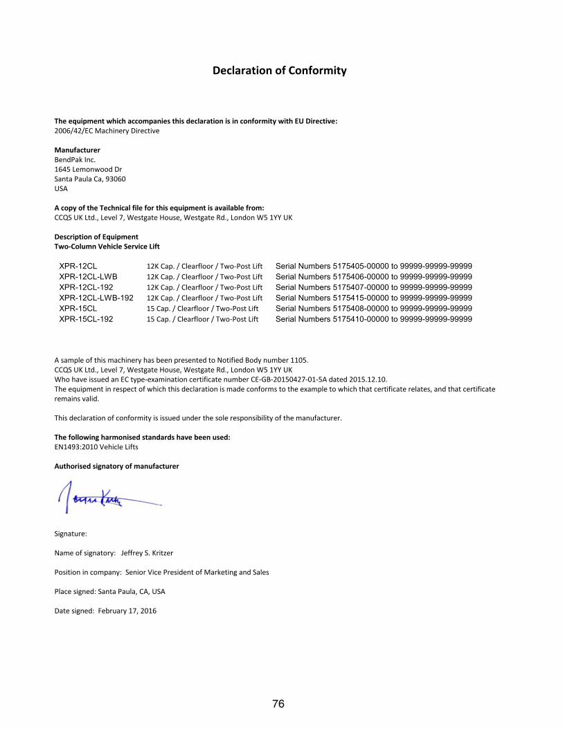
76
Declaration of Conformity
The equipment which accompanies this declaration is in conformity with EU Directive: 2006/42/EC Machinery Directive Manufacturer BendPak Inc. 1645 Lemonwood Dr Santa Paula Ca, 93060 USA A copy of the Technical file for this equipment is available from: CCQS UK Ltd., Level 7, Westgate House, Westgate Rd., London W5 1YY UK Description of Equipment Two-Column Vehicle Service Lift
XPR-12CL 12K Cap. / Clearfloor / Two-Post Lift Serial Numbers 5175405-00000 to 99999-99999-99999 XPR-12CL-LWB 12K Cap. / Clearfloor / Two-Post Lift Serial Numbers 5175406-00000 to 99999-99999-99999 XPR-12CL-192 12K Cap. / Clearfloor / Two-Post Lift Serial Numbers 5175407-00000 to 99999-99999-99999 XPR-12CL-LWB-192 12K Cap. / Clearfloor / Two-Post Lift Serial Numbers 5175415-00000 to 99999-99999-99999 XPR-15CL 15 Cap. / Clearfloor / Two-Post Lift Serial Numbers 5175408-00000 to 99999-99999-99999 XPR-15CL-192 15 Cap. / Clearfloor / Two-Post Lift Serial Numbers 5175410-00000 to 99999-99999-99999
A sample of this machinery has been presented to Notified Body number 1105. CCQS UK Ltd., Level 7, Westgate House, Westgate Rd., London W5 1YY UK Who have issued an EC type-examination certificate number CE-GB-20150427-01-5A dated 2015.12.10. The equipment in respect of which this declaration is made conforms to the example to which that certificate relates, and that certificate remains valid. This declaration of conformity is issued under the sole responsibility of the manufacturer. The following harmonised standards have been used: EN1493:2010 Vehicle Lifts Authorised signatory of manufacturer
Signature: Name of signatory: Jeffrey S. Kritzer Position in company: Senior Vice President of Marketing and Sales Place signed: Santa Paula, CA, USA Date signed: February 17, 2016

77
TWO‐POST LIFTS/FOUR‐POST LIFTS WARRANTY Better Products – Better Service – Better Value
Duration: From the date of purchase by original Purchaser or 60‐24‐12 months from the date of shipment by BendPak or whichever comes first. Five Years (60-Months) Warranty on the lift structure Two Years (24-Months) Warranty on the hydraulic cylinder(s) and power unit One Year (12-Months) Warranty on operating components One Year (12-Months) Labor Warranty on site or at factory One Year (12-Months) Free-Shipping* on ground‐freight charges related to warranty performance
Limited Warranty 1. Who gives this warranty (Warrantor): BendPak Inc., 1645 Lemonwood Dr., Santa Paula, CA 93060 2. Who receives this warranty (Purchaser): The original Purchaser (other than for purpose of resale) 3. What products are covered by this warranty: Any BendPak Two‐Post or Four‐Post Vehicle Service Lift** 4. What is covered under this warranty: manufacturer defects due to material and/or workmanship with the exceptions noted below. 5. What is not covered under this warranty:
a. Any failure that results from Purchaser’s abuse, neglect or failure to operate, maintain or service product in accordance with instructions provided in the owner’s manual(s) supplied
b. Any damage caused by overloading lift beyond rated capacity c. Items or service normally required to maintain the product, i.e. lubricants, oil, etc. d. Items considered general wear parts such as rubber pads, lifting cables, etc. unless wear or failure is a direct result of
manufacturer defect due to material and/or workmanship e. Any component damaged in shipment or any failure caused by installing or operating lift under conditions not in accordance with
installation and operation guidelines or damaged by contact with tools or surroundings f. Motor or pump failure caused by rain, excessive humidity, corrosive environments or other contaminants g. Rusted components due to improper maintenance or corrosive environments h. Cosmetic defects that do not interfere with product functionality i. Damage due to incorrect voltage or improper wiring j. Any incidental, indirect, or consequential loss, damage, or expense that may result from any defect, failure, or malfunction of
BendPak Inc. product k. All electrical components (excluding power unit) are guaranteed for one year against defects in workmanship and/or materials
when the lift is installed and used according to specifications. 6. Responsibilities of Warrantor under this warranty: Repair or replace, at Warrantor’s option, component which is defective, has
malfunctioned and/or failed to conform within duration of the warranty period. BendPak Inc. will pay reasonable labor costs for the first 12 months only
7. Responsibilities of Purchaser under this warranty: a. Provide dated proof of purchase and maintenance records b. In some cases, components may be required to be shipped to the nearest BendPak Authorized Service Center. Freight costs, after
12‐months, must be borne by the Purchaser. c. Use reasonable care in the operation and maintenance of the products as described in the owner’s manual(s).
8. When Warrantor will perform repair or replacement under this warranty: Repair or replacement will be scheduled and serviced according to the normal work flow at the servicing location, and depending on the availability of replacement parts.
*Free‐shipping applies to direct shipping points within the 48 continental United States. Rural area shipping surcharge may apply for remote addresses. **For all BendPak brand Two‐Post or Four‐Post Vehicle Service Lifts (excluding specialty lifts, high rise, commercial parking, material handling, or models for particular purpose) manufactured on or following 1/1/2011.
Limitation of Liability BendPak/Ranger shall have no obligation pursuant to this Warranty with respect to products which in our sole judgment have been altered damaged, misused, abused, badly worn, lost or improperly maintained. This Warranty is null and void if the customer or any other person other than an authorized representative of BendPak/Ranger has made any attempt to service or modify the tool prior to its return to BendPak/Ranger under this Warranty. In no event will either party be liable for any damage caused by the other party's failure to fulfill its responsibilities under these terms and conditions. In no event will either party be liable for any lost profits, lost savings, incidental damage, or other economic consequential damages BendPak/Ranger products are provided and sold as is without any express or implied warranties including warranties of merchantability or fitness for particular purpose. No warranties, expressed or implied, will apply after this period. BendPak may modify these terms and conditions at any time by either providing the customer with written notice or posting such revised terms on www.bendpak.com. Such revised terms shall be effective thirty days from the date of such written notice or posting.

78
MAINTENANCE / INSPECTION RECORDS
____________________________________________________________________
____________________________________________________________________
____________________________________________________________________
____________________________________________________________________
____________________________________________________________________
____________________________________________________________________
____________________________________________________________________
____________________________________________________________________
____________________________________________________________________
____________________________________________________________________
____________________________________________________________________
____________________________________________________________________
____________________________________________________________________
____________________________________________________________________
____________________________________________________________________
____________________________________________________________________
____________________________________________________________________
____________________________________________________________________
____________________________________________________________________
____________________________________________________________________

79
NOTES
____________________________________________________________________
____________________________________________________________________
____________________________________________________________________
____________________________________________________________________
____________________________________________________________________
____________________________________________________________________
____________________________________________________________________
____________________________________________________________________
____________________________________________________________________
____________________________________________________________________
____________________________________________________________________
____________________________________________________________________
____________________________________________________________________
____________________________________________________________________
____________________________________________________________________
____________________________________________________________________
____________________________________________________________________
____________________________________________________________________
____________________________________________________________________
____________________________________________________________________

80