Embed Size (px)
Citation preview

I
NS
TALL
AT
ION
& O
WN
ER
’S M
AN
UA
L p. 1 of 20
UTV UNIVERSAL Plow Kit
6’ Wide Snow Plow (Self-Contained Hyd.) (p/n: 1UTVP = factory assembled)
(p/n: 1UTVP-1 = assembly required)
For the 1UTVP version, the instructions are on pages 3-6. Approxi-mate installation time: 1/2 an hour. For the 1UTVP-1 version, the assembly instructions are on pages 11-19. Approximate installation time: 3 hours. Page 2 safety and maintenance info. pertain to both p/n’s (both plows kits).
These instructions are only valid for the Plow portion. Please see separate in-structions for the required Mount Kit. Note: Front Heavy Duty Springs or Heavy Duty Spring Damper Assembly are required if plow is installed. Total weight = 254 lbs. for either plow kit (frame mount kits add an additional 30 lbs. max. for a grand total of 284 lbs. max.) NOTE: Jack Legs and Blade Markers are discussed here, but are separately purchased items.
manual p/n: IM-UTVP (Rev. G) 10/04/2019
Do not attempt to install or operate this plow until you read and understand all warnings and instructions in this manual or on the plow. Failure to read all warnings and instructions could lead to serious injury or death.
shown with optional blade markers (p/n: 8SV-TBP37) (a set of two with hardware)
shown with optional jack leg (p/n: 1UTVPJL) (includes hardware)

SAFETY INFORMATION: WARNING: Cabs, blades, and general accessories add additional weight to the base vehicle. Deduct the accessory’s total weight from the vehicle’s rated capacity includ-
ing driver and passenger. Never operate the vehicle outside of its rated weight capacity. WARNING: Exposure to Carbon Monoxide can cause illness, serious injury
or death. Never operate vehicle if suspicious of Carbon Monoxide. Inspect exhaust system for leaks monthly. Leaks can result from loose connections, corrosion, cracks or
other damage to the exhaust manifold. If leaks are found, repair or replace exhaust system. Do not use vehicle until repair or replacement is complete. WARNING: Serious injury or death:
Never stand or ride on the plow assembly. Never operate the plow near pets or other people. Never leave the vehicle running unattended with plow attached.
Never plow or carry plow at high speeds. Never clean or perform maintenance with plow raised. Never clean or service with plow in tripped condition. Never dislodge an obstruction with any part of the body. Warning - This attachment affects the handling performance. Warning - Before starting installation, park RTV in a flat area, ensure parking brake is en-
gaged, and engine is turned off. HELPFUL REMINDERS:
A. Check carton contents prior to beginning installation. B. Work in an organized area large enough to fit vehicle and plow. C. Have the required tools ready to speed up the installation time. D. Have a helper available to help move heavy parts and assemblies.
The Installation should be done by “qualified personnel”.
MAINTENANCE NOTES: Check and tighten all fasteners in the plow assembly and vehicle mounting after ini-
tial use and every 5 hours of use thereafter. After every 10 hours of use, lubricate all pivot bolts, pins, snap lock latches, and
any other moving parts in the plow assembly with all-season grease. Supplies required for 1UTVP (factory assembled plow):
TOOLS REQUIRED:
p. 2 of 20
Dielectric Grease AW 32 Plow Oil
!
!
!
p. 3 of 20
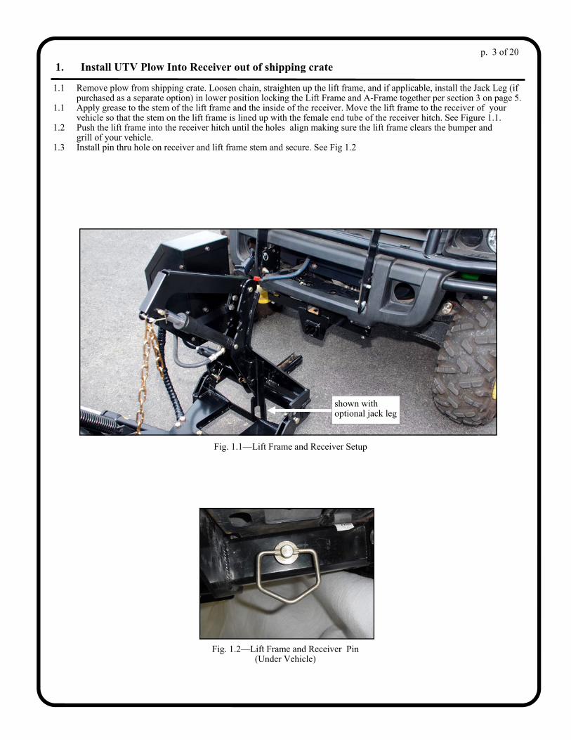
1. Install UTV Plow Into Receiver out of shipping crate 1.1 Remove plow from shipping crate. Loosen chain, straighten up the lift frame, and if applicable, install the Jack Leg (if purchased as a separate option) in lower position locking the Lift Frame and A-Frame together per section 3 on page 5. 1.1 Apply grease to the stem of the lift frame and the inside of the receiver. Move the lift frame to the receiver of your vehicle so that the stem on the lift frame is lined up with the female end tube of the receiver hitch. See Figure 1.1. 1.2 Push the lift frame into the receiver hitch until the holes align making sure the lift frame clears the bumper and grill of your vehicle. 1.3 Install pin thru hole on receiver and lift frame stem and secure. See Fig 1.2
Fig. 1.1—Lift Frame and Receiver Setup
Fig. 1.2—Lift Frame and Receiver Pin (Under Vehicle)
shown with optional jack leg

p. 4 of 20
2. Alternate Install UTV Plow Into Receiver using shipping crate 2.1 Remove top and sides from shipping crate. Cut crate as shown to allow front wheels of UTV to enter crate base. Move UTV to align with stem on Lift Frame of plow. See Figure 2.1. Front wheels of UTV may encroach into the cutout made on the crate base. Slide pallet jack under crate and lift so that stem on Lift Frame and Receiver are in line. Apply grease on stem of Lift Frame. 2.2 Unhook chain from Lift arm and readjust so that there is plenty of slack in chain approximately 4-5 free links after clevis pin. Unbolt shipping straps in front and cut green shipping strap on Lift Frame stem. Hold onto lift frame making sure to keep it from dropping forward. Then move vehicle so that stem on Lift frame slides into Mount receiver and slide all the way into mount making sure the lift frame clears the bumper and grill of your vehicle. Install pin thru hole on receiver and lift frame stem and secure. 2.2 Plug in 7 Pin connector from Pump Assembly to mating Plug on Vehicle. Activate plow and lift off pallet base, move pallet base away and lower plow to ground.
Fig. 2.2—Lift Frame and Receiver Setup Fig. 2.3—Lift Frame and Receiver Pin (Under Vehicle)
Fig. 2.1—Lift Frame and Receiver Setup
shown with optional jack leg

p. 5 of 20
Fig. 10.1—Shocks Set to Stiffest Setting
3. Jack Leg Operation (skip this section if this optional item was not purchased) 3.1 Before removing plow from vehicle, remove the two cotter pins and flat washers from the jack leg and flip the leg over so that the foot pad is down. 3.2 Make sure that the hook on the leg captures the back strap of the A-Frame. Re-install leg through the original holes and attach with washers and pins. Per figure 11.2
Warning: Never operate plow with rear jack leg in lower position. Damage will occur.
Fig. 11.1B— Jack Leg Pins
Fig. 11.2—Jack Leg in use
!

Fig. 4.1 A-Frame and Lift Frame Mounting Tabs
Fig. 4.3 Level A-Frame
4. Adjusting A-Frame to Lift Frame 4.1 Apply grease to the pivot holes in the rear of the A-Frame and the lower Lift Frame. 4.2 Align the Tabs of the A-Frame with tabs on the Lift Frame. Three pivot holes are provided on lift frame to accommodate varying vehicle heights. 4.3 Make sure A-Frame is level with the ground and insert ¾” x 2” long clevis pin into the appropriate hole. Double check for levelness and install cotter pins. 4.4 Adjust Lift Arm and Lift Cylinder so that 2” of chrome on the lift cylinder is showing. Attach lift chain to Lift Arm with clevis pin so that a slight amount of slack is left in the chain.
Fig. 4.2 A-Frame and Lift Frame Mounting Tabs
p. 6 of 20
Lift Frame
Pivot Pin A-Frame
shown with optional jack leg

UTV Universal Plow Kit (p/n’s: 1UTVP and 1UTVP-1)
6’ Wide Snow Plow (Self contained Hyd.)
p. 7 of 20
shown with optional Blade Markers (p/n: 8SV-TBP37)
shown with optional Jack Leg (p/n: 1UTVPJL)

p. 8 of 20
supplied w/ optional jack leg
UTV Universal Plow Kit (p/n’s: 1UTVP and 1UTVP-1)
6’ Wide Snow Plow (Self contained Hyd.)

p. 9 of 20 UTV Universal Plow Kit (p/n’s: 1UTVP and 1UTVP-1)

p. 10 of 20
UTV Universal Plow Kit (p/n’s: 1UTVP and 1UTVP-1)
6’ Wide Snow Plow (Self-Contained Hyd.)
48 Hand Held Plow Controller 1HHC 1
49 40" long Hose HYDR04 2
50 18" long Hose HYDR05 1
51 Installa on Instruc ons IM‐1UTVP 1
52 90° Elbow with Patch Sealant for Angle Cylinder 1TBP98G 2
53 45° Elbow for Li Cylinder 1TBP98H 1
54 1/4‐20 x 3/4" long Hex Head Bolt (Grade 5) (plated) 70‐00‐0021 7
55 1/4‐20 Hex Flange Nut Nyloc 72‐21‐0008 1
57 3/8‐16 x 1" long Flanged Hex Head Bolt 70‐05‐0064 2
58 3/8‐16 Hex Flange Nut Nyloc 72‐21‐0086 2
59 Harness Spiral Wrap Cut 20" long 1TBP129‐20 1
60 1/2‐13 x 4‐1/2" long Hex Head Bolt (Grade 5) (plated) V4207P18 2
61 1" Dia. x 12" Stroke S.A. Hydraulic Cylinder V4207P1 2
62 1/4" x 12" long Black Nylon Wire/Hose Tie V4207P15 8
63 A‐Frame Pinch Guard 1TBP29PG 1
64 Wire Harness, Main, Hyd. UTV Plow KX9UTP‐WHHLA02 1
65 Wire Harness, Ba ery, Hyd. UTV Plow KX9UTP‐WHHLA03 1
DC Motor 12‐Volt 1TBM300 1
Angle/Li Valve with Coil Kit 1TBM303 1
Float Valve with Coil 1TBM305 1
Pump Assembly Kit 1TBM307 1
Hydraulic Pump Filter Kit 1TBM308 1
Hydraulic Power Unit Reservoir Kit 1TBM309 1
Fixed Relief Valve 1TBM310 1
Return Tube Kit 1TBM311 1
Reservoir Cap 1TBM312 1
12‐Volt Motor Solenoid 1TBP61A 1
Wire Harness Bracket Kit, U lity Vehicle Plow KX9UTP‐WHBK 1

Pages 11-19 are for unassembled plow kit p/n: 1UTVP-1 only. TOOLS REQUIRED:
Set of standard and metric sockets Set of standard and metric open end wrenches One 3/8” Drive Ratchet Pliers Dielectric Grease AW 32 Plow Oil
p. 11 of 20
1. Trip-frame to Moldboard Assembly 1.1. Per fig 1.1, locate the steel moldboard, trip frame, two 1/2-13 x 2 1/2” bolts, and two 1/2-13 Nylock locking nuts. Apply all-season grease to the mating surfaces on the trip frame and moldboard rib. As shown, line up the mounting hole in the trip frame with the mounting hole on the moldboard rib (near the bottom). Install into the mounting holes a 1/2-13 x 2” bolt as shown. Install a 1/2-13 Nylock nut on the back side of the bolt. Repeat installation of hardware for the right side, orienting the bolt head to face away from the center of the moldboard. Tighten the Nylock nuts until all thread slack is removed from the assembly while allowing the trip-frame to rotate freely. 2. Trip Spring Installation 2.1 Per fig 2.1, locate the two trip springs, two eye bolts, two 3/8-16 Nylock hex nuts, and two 3/8” washers. 2.2 Note: Trip frame is shown an exaggerated distance away from moldboard to clarify trip spring placement. Per Fig 2.2, hook one end of the trip spring through the lower trip spring mount. Hook the eyebolt on the other end of the spring and insert the threaded section up through the hole in the upper spring mount. Install a 3/8” washer, then a 3/8” Nylock hex nut on the eyebolt. Repeat above for the second trip spring. 2.3 Set the spring tension by tightening the Nylock nut until a sheet of paper can slide between two coils on the spring. Be sure to set tension evenly in both springs.
Fig 2.1—Trip Springs and Hardware
Fig. 2.2—Trip Spring Installation
attach springs as shown
Fig. 1.1—Trip Frame to Moldboard
apply grease here on each end before
assembling
ref.: hyd. cyl. installed in a
later step

p. 12 of 20
3. A-Frame Installation 3.1 Per fig 3.1, locate the A-frame, one 1/2-20 x 3.5” hex head bolt, one 1/2-20 conical locking hex nut, and one 1/2” washer. Apply all-season grease to the top and bottom surface of the A-frame around and in the 1/2” bolt hole. Grease should extend about an inch away from the center of the hole. 3.2 Per fig. 3.2, slide the A-Frame into the trip frame pocket, aligning the 1/2” bolt holes on both assemblies. Install the 1/2-20 x 3.5” hex head bolt with a 1/2” washer under the head of the bolt. Then thread on the lock nut. Tighten until all slack is removed from the bolt while the A-frame is allowed to rotate freely in the trip frame pocket. 3.3 Apply grease to the under side of the Pinch Guard in the area where it will contact the trip frame. Position the Pinch Guard bracket with the spacers down and with the four holes lined up with the corresponding holes in the top of the A-Frame. Fasten the bracket using four 1/2-13 x 1 1/2” hex head bolts and 1/2” lock washers. Make sure the A-Frame pivots in both directions.
Fig. 3.1—A-Frame and Hardware
A-frame Apply grease
here
Fig. 3.2—A-Frame and Trip Frame
Install 1/2-20 x 3.5 bolt
Grease top of A- frame & under Pinch Guard

p. 13 of 20
4. Chain Shackle Installation 4.1 Locate the Lift Chain Shackle per fig 4.1 4.2 Per fig 4.2, slide Lift Chain through shackle then insert the clevis pin on the lift chain shackle into the lifting hole on the trip frame. Slip Cotter pin into hole on clevis pin and bend back to lock in place.
Fig. 4.1—Lift Chain Shackle
Fig. 4.2—Shackle installed on Trip Frame
Trip Frame
Lifting Hole
5. Attach Lift Arm to Lift Frame 5.1 See fig. 5.1. Apply thread sealer on 45° Elbow and thread into port on lift cylinder. Making sure it points towards the piston end of the cylinder. 5.2 Apply grease to the pivot holes of the Lift Arm, Lift Cylinder, and the Upper Lift Frame. Place the fixed end of the Lift Cylinder between the vertical plates of the Lift Frame. Make sure that the hydraulic inlet is pointing away from the machine, line up lower hole in lift frame with rod hole in Lift Cylinder. 5.3 Place 1/2” x 2 1/2” clevis pin in place to hold. Place the back end of the Lift Arm between the vertical plates of the Lift Frame. 5.4 Line up upper hole in lift frame with rear hole in lift arm. Place 1/2” x 2 1/2” clevis pin in place to hold. 5.5 Place the piston end of the Lift Cylinder between the plates of the Lift Arm as shown, line up holes and place 1/2” x 2” clevis pin in place to hold. Then insert cotter pins in all (3) clevis pins to lock in place per Fig 5.1 6. Install Lift Frame into Mount Kit Receiver 6.1 Apply grease to the stem of the lift frame and the inside of the receiver. Move the lift frame to the receiver of your vehicle so that the stem on the lift frame is lined up with the female end tube of the receiver hitch. 6.2 Push the lift frame into the receiver hitch until the holes align making sure the lift frame clears the bumper and grill of your vehicle. 6.3 Install pin thru hole on receiver and lift frame stem and secure. See fig. 6.3.
Fig. 5.1 Lift Frame and Lift Arm
Lift Frame Lift Cylinder
foot pad on optional Jack Leg
Lift Arm
Lift Cyl Mtg Hole
Fig. 6.3 Pin on Receiver

Fig. 7.1 A-Frame and Lift Frame Mounting Tabs
7. Attach A-Frame to Lift Frame 7.1 Apply grease to the pivot holes in the rear of the A-Frame and the lower Lift Frame. See fig. 7.1. 7.2 Align the Tabs of the A-Frame with tabs on the Lift Frame. Three pivot holes are provided on lift frame to accommodate varying vehicle heights. 7.3 Make sure A-Frame is level with the ground and insert ¾” x 2” long clevis pin into the appropriate hole. Double check for level and install cotter pins. See fig. 7.3. 7.4 Adjust Lift Arm and Chain so that 2” of chrome on the lift cylinder is showing. Attach lift chain to Lift Arm with clevis pin so that a slight amount of slack is left in the chain. See fig. 7.4.
Fig. 7.3 A-Frame and Lift Frame Mounting Tabs
Fig. 7.4 Attach Chain
p. 14 of 20
Lift Frame
Pivot Pin A-Frame

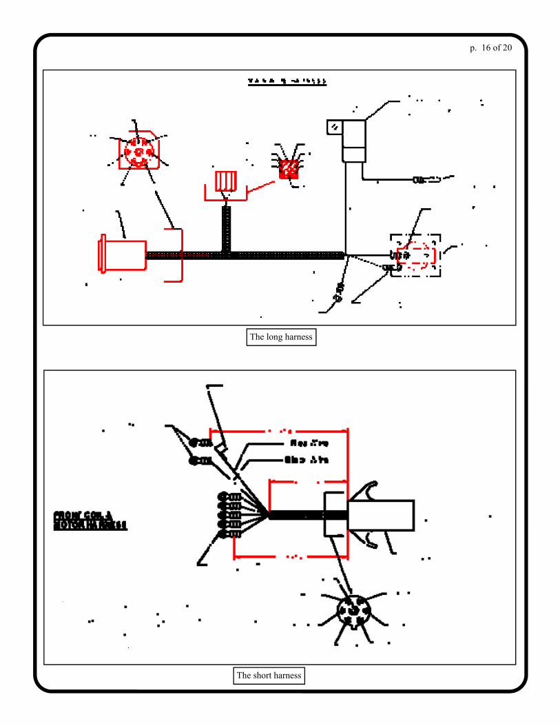
8. Pump to Lift Frame 8.1. Per figures 8.1, 8.2, and 8.3, position Pump Assem- bly, Side Cover, and Mounting Bracket up against the top of the lift frame matching up mating holes on lift frame and mounting bracket. Using the two 3/8-16 x 1” bolts, and two 3/8-16 Nylock nuts, attach bracket to lift frame. Tighten the Nylock nuts until all thread slack is removed from the assembly. 8.2 Both wiring harnesses are shown in the electrical diagram at the bottom of the page. At location A, use a #10 x 3/4” long self-drilling screw. At location B, use two #10 x 3/4” long self-drilling screws and two 1/4” washers. See the next two pages for addition electrical information. Plug the 7 pin connector from the hydraulic pump and motor assembly into the vehicle end of the 7 pin connector.
p. 15 of 20
Fig. 8.1—Pump and cover installation
Fig. 8.3—Pump and cover installation
Pump Ass’y. Side Cover
Mounting Bracket
Fig. 8.2—Pump and cover installation
short harness
one end of the long harness
p. 16 of 20
The long harness
The short harness

Photo shows specific coil studs for 16 gauge wire connections.
p. 17 of 20
BLUE WIRE
WHITE WIRE
GREEN WIRE
RED WIRE

p. 18 of 20
9. HYDRAULIC ANGLE CYLINDERS AND LIFT CYLINDER: 9.1 Apply thread sealer on 90° Elbow and thread into port on angle cylinder. Making sure one points towards the piston end of the cylinder and one points towards the fixed end of the cylinder. 9.2 Place the fixed end of each angle cylinder into its respective bracket under the plow A-frame making sure that 90° Elbow is in orientation shown. Insert 1/2-13 x 4 1/2” bolts through the plow A-frame, the stationary ends of the angle cylinders, and the lower cylinder brackets of the A-frame. Fasten and tighten using 1/2-13 lock nuts. See Fig. 9.2. (Do not over tighten, 1 to 3 threads should be showing past nut) 9.3 Attach the piston end of the angle cylinders between the brackets at the outer ends of the back side of the plow trip frame using 1/2-13 x 2 1/2” bolts. Fasten and tighten using 1/2-13 lock nuts. See Fig. 9.3. (Do not over tighten, 1 to 3 threads should be showing past nut) 9.4 Attach and tighten the free end of each of the 40” long hydraulic hoses to the swivel elbow in its respective angle cylinder. The hydraulic hose with the blue mark coming out of port C1 on pump manifold will be attached to the left side cylinder (driver’s side). See Fig. 9.4. 9.5 Attach and tighten the swivel end of the 12” long hydraulic hose to the elbow on the fixed end of the lift cylinder that was installed previously. See Fig 9.5.
1/2-13 x 4 1/2” Hex Bolt
Fig. 9.2 Angle Cylinder Fixed End
Fig. 9.3 Angle Cylinder Piston End
1/2-13 x 2 1/2” Hex Bolt
Fig. 9.4 Angle Cylinders fixed End Hose orientation
Swivel Elbows
Fig. 9.5 Lift Cylinder Hose orientation
Lift Cylinder Hose

10. FILL THE SYSTEM: 10.1 At this point, hook the battery terminals up to the main wiring harness connecting the positive leads first then the negative leads last. 10.2 Per fig. 10.2, remove the filler cap and fill tank with electric plow oil (AW 32). Stand clear of the plow. Turn the controller on and then using the controller, work the cylinders left and right and up and down a few times working the air from them, make sure oil is about 1/2” from top of tank. If the oil level in the tank gets low, add to it until the system is bled of air. 10.3 Place cover over pump and bracket and attach with (7) 1/4-20 screws provided. See Figure 10.3. 10.4 Double check all connections and re-tighten all bolts and unit is ready for operation. USE ONLY ELECTRIC PLOW OIL (AW 32)
p. 19 of 20
Hydraulic Tank
Fig. 10.2 Hydraulic tank
Fig. 10.3 Final Assembly

11. TROUBLE SHOOTING A HYDRAULIC CYLINDER LEAK: 11.1 Oil seepage may stop on its own once the dry cylinders are fully cycled several times (5 to 10 times) to get the seals to reset
properly. If this does not resolve the issue, proceed to step 11.2. 11.2 Disconnect the main wiring harness before servicing. 11.3 Per fig. 11.3, loosen the gland nut on the particular leaking cylinder. Additional oil may escape. Take care to place a bucket
or rags below the cylinder. Loosening the gland nut will allow the seals to relax and re-align. There is no need to remove the gland nut entirely. Do not remove the rod from the cylinder.
11.4 Hand tighten the gland nut. 11.5 Tighten the gland nut an additional 1/8 to 1/4 turn with a wrench. 11.6 Repeat section 10.2 on the previous page to bleed air out of the cylinder. It’s important to cycle the affected cylinder several
times (5 to 10 times). 11.7 Wipe down the cylinder with a rag and inspect for leaking oil. 11.8 If necessary, repeat the process of tightening the gland nut an additional 1/8 turn and bleeding the cylinder until free of
leaks. Repeat another 1/8 turn if still leaking. Note: proceed only in 1/8 turn increments and continue cycle testing between adjustments.
p. 20 of 20
Fig. 11.3 repairing a Hydraulic Cylinder leak
GLAND NUTS