Embed Size (px)
DESCRIPTION
Pmdg J41
Citation preview

FOR SIMULATOR USE ONLY 04SEPT09v.1.00.0
Aircraft OPERATING Manual
Copyright © 2009Precision Manuals Development Group
All Rights Reserved
FOR SIMULATOR USE ONLY 04SEPT09v.1.00.0
This manual was compiled for use only with the PMDG Jetstream 41 simulation for Microsoft® Flight Simulator™ X. The information contained within this manual is derived from multiple sources and is not subject to revision or checking for accuracy. This manual is not to be used for training or familiarity with any aircraft. This manual is not assumed to provide operating procedures for use on any aircraft and is written for entertainment purposes.
It is a violation of the owner’s copyright to distribute this document or any portion thereof without permission of the author. The Precision Manuals Development Group Web Site can be found at: http://www.precisionmanuals.com
Copyright© 2009 Precision Manuals Development Group
This manual and all of its contents, pages, text and graphics are protected under copyright law of the United States of America and international treaties. Duplication of this manual is prohibited. Permission to conduct duplication of this manual will not be subcontracted, leased or given.
Microsoft, the Microsoft Logo and Microsoft Flight Simulator are registered trade-marks of the Microsoft Corporation. BAE, the Jetstream name and certain brand marks are the property of BAE Systems. Some graphics contained in this manual were taken directly from the simulator and altered in order to suite duplication on a printed page. All images contained in this manual were used with permission.
2
Aircraft Operating Manual
· INTENTIONALLY LEFT BLANK ·
Disclaimer and Copyright Information

FOR SIMULATOR USE ONLY 04SEPT09v.1.00.0
�
Table of Contents
Aircraft Operating ManualMain Table of Contents
1. Introduction ............................................................ pg. 1-1
2. Terminology ........................................................... pg. 2-1
3. Limitations ............................................................. pg. 3-1
4. Normals ................................................................. pg. 4-1
5. Emergency/Abnormals ........................................... pg. 5-1
6. Non-Routine ........................................................... pg. 6-1
7. Performance .......................................................... pg. 7-1
8. Systems ................................................................. pg. 8-1
· INTENTIONALLY LEFT BLANK ·

FOR SIMULATOR USE ONLY 04SEPT09v.1.00.0
1
Introduction
Aircraft Operating Manual
About this Manual
This PMDG Jetstream 41 Aircraft Operating Manual is designed to help simulator pilots learn the mechanical systems and technical details of the PMDG Jetstream 41. This manual shows how each system is configured, how it is operated and how the crew can interact with the airplane.
How to use this Manual
This manual should be used by simulator pilots who are interested in learning how the Jetstream 41 operates and how to utilize the various systems on the airplane effec-tively in all phases of flight.
The Jetstream 41 is a fairly complex regional airliner. In spite of this complexity, it is important that pilots have a comprehensive understanding of what each system on the airplane is doing, how it is controlled, and what operations might be impeded in the event of a failure.
This manual is broken into chapters with each chapter providing detail on one particu-lar subsystem or system type. You can read through an individual chapter to learn how a system on the Jetstream 41 is operated, or you can read through the entire manual section by section to learn how the entire airplane is operated.
Gaining the most from this Manual
The best method to improve your understanding of this airplane is to launch the simu-lator, then load the Jetstream 41 and sit in the virtual cockpit while reading through this material. This technique will allow you to touch, feel and explore the systems operation of the Jetstream 41 and see how the airplane responds to pilot interaction.
Introduction

FOR SIMULATOR USE ONLY 04SEPT09v.1.00.0
2
Aircraft Operating ManualIntroduction
A Turbo-prop Regional Airliner Reborn!The Jetstream 41 turboprop regional airliner, manufactured by BAE Systems, is a major development of the Jetstream 31/32 regional airliner family, which entered ser-vice in 1982. The Jetstream 31 and the Jetstream 32EP (enhanced performance) are 19-seat turboprop airliners. The stretched Jetstream 41 development was announced in 1989, the first flight took place in 1991 and the aircraft entered service in 1992. The goal was to compete directly with 30-seat aircraft like the Embraer Brasilia, Dornier 328 and Saab 340.
The Jetstream 41’s stretched fuselage is 16 ft (4.88 m) longer, consisting of an 8 foot (2.5 m) plug forward of the wing and a 7 ft 9 in (2.36 m) plug to the rear; the fuselage design was completely new and did not contain any parts of the old fuselage. The new design required an increased wing span, which also included reworked ailerons and flaps. The wing was mounted below the fuselage in order for it not to carry through the cabin aisle, which also led to larger wing root fairings which increased baggage capacity.
The Jetstream 41 is fitted with Garrett TPE331-14 engines (now owned by Honey-well), and delivered 1,500 shp (1,120 kW) and later 1,650 shp (1,232 KW). They were mounted in new nacelles which increased ground clearance. The flightdeck was equipped with a modern EFIS setup, as well as a new windscreen arrangement. The J41 was the first turbo-prop certified to both JAR25 and FAR25 standards. In January 1996, the J41 became part of the Aero International (Regional) (AI(R)), a marketing consortium consisting of ATR, Aérospatiale (of France), Alenia (of Italy), and British Aerospace.
Over 90 Jetstream 41 aircraft are operational worldwide in both 29/30 seat commuter and 14-seat corporate shuttle configurations.
An accurate, detailed simulation of the Jetstream 41 has been sorely missing from desktop flight simulation... Until Now!
After being in development for 9 months, PMDG’s award winning development team is proud to release this faithfully reproduced aircraft! In traditional PMDG style, no effort was spared during this extensive development process and we are certain the J41 will quickly become your favorite regional turbo prop simulation!

FOR SIMULATOR USE ONLY 04SEPT09v.1.00.0
�
Aircraft Operating ManualDevelopment Team
The PMDG Jetstream 41 Development Team
The PMDG development team is recognized throughout the simulation community for producing ground breaking airliner simulations. The PMDG J41 was developed by the following individuals:
· Jason Brown · Armen Cholakian · Matt Kaprocki · Captain Robert S. Randazzo · Vincent M. Scimone · Pete Sterling · Dr. Evangelos M. Vaos · Henning van Rensburg
Guest Developer - XLS-GNS FMS
· Ernie Alston

FOR SIMULATOR USE ONLY 04SEPT09v.1.00.0
4
Aircraft Operating ManualBeta Testers
Thank You!
In any project of this scope, there is always a very dedicated development team. For a development team to succeed, there must be an unwavering commitment to the fine detail of the product and to the product quality. While the dedicated experts on the PMDG development team have raised realism in flight simulation to a science, we depend very heavily upon the dedication of our beta team to make our products the highest quality possible. Without these fine individuals, it simply would not be pos-sible to bring you the quality level for which PMDG products are known.
We would like to thank the following individuals for their time, attention to detail, can-dor, sense of humor and sense of urgency during the development of this product.
· Mark Adeane · David Bartoli · Steve Cotterill · Clay Dopke · Dan Downs · Jhan Jensen · Mats Johansson · Sam Johnnson · Kurt Kalbfleisch · Nick Landolfi · George Morris · Joe Panford · Tero Partanen · Bruce Ullyot · Steve Weiher · J. R. Whittaker · Stan Winke · Bryan York · Urs Zwyssig

FOR SIMULATOR USE ONLY 04SEPT09v.1.00.0
�
Aircraft Operating ManualThank You
We would also like to put special notice on our Senior Beta Tester, George Morris, who has been beta testing for PMDG for a decade as of October, 2009. A decade in any endeavor is admirable, but a decade in a job that get such poor recognition is truly inspiring. George, thank you for your efforts during the past decade, and we look forward to working with you over the next one!
All of us at PMDG would also like to thank Lauren Crocker at Northstar Aviation for helping us to arrange access to the J41s used in the creation of this product. We would also like to thank the many the fine technicians at Northstar Aviation’s facility in Mena, Arkansas who, in spite of conducting a last minute engine change in order to ship a refurbished J-41 overseas, were gracious and accommodating of every request as we photographed, measured and recorded around their work.

FOR SIMULATOR USE ONLY 04SEPT09v.1.00.0
Dedication
At PMDG we do not normally dedicate our products to specific groups or individuals, but with this project we decided to do something a bit different. The BAe JetStream 4100 was operated in the United States by powerful little company called Atlantic Coast Airlines. ACA, based out of Washington Dulles International Airport had humble beginnings with a handful of borrowed J-31s and EMB-120s, but grew to be one of the most powerful (and profitable) regional airlines that the industry had seen as of the first few years of this millennium. Operating more than 150 aircraft, ACA covered the eastern US flying in the colors of United and Delta airlines and was an industry leader in performance, quality of life for employees and innovative approaches to the complex business of regional airline operations. Unfortunately, ambition, disregard for history and poor timing combined to make this airline an anecdote for history, forgot-ten by all but those who worked there.
At its peak, Atlantic Coast Airlines was the world’s largest operator of JetStream 41 aircraft. For this reason, we dedicate the effort required to produce this simulation to the men and women who worked there. From the maintenance shop to the ramp, the gate areas, ticket counters, dispatch desks, cockpits, cabins and yes, even the crew scheduling desks, ACA employees ran a large airline that never stopped feeling like a big (if not sometimes dysfunctional) family.
ACA may be gone, but the friendships made there live on. This airplane is for all of you.
Captain Robert S. RandazzoPrecision Manuals Development Grouphttp://www.precisionmanuals.com
DedicationAircraft Operating Manual
�

FOR SIMULATOR USE ONLY 04SEPT09v.1.00.0
1
Aircraft Operating Manual
Terminology
Terminology
Abbreviations used in this manual have the following meanings:
AA ampereAAL above aerodrome levelac alternating currentAcc accumulatorACP audio control panelADF automatic direction finderADI attitude direction indicatorAFCS automatic flight control systemAGL above ground levelAh ampere-hourAHRS attitude and heading reference systemALT altitudeAMSL above mean sea levelA/P autopilotAPR (engine) automatic performance reserveAPR (flight director/AFCS) approachASI airspeed indicatorATC air traffic controlATT attitude (EFIS)AUW all up weight
-------------------------------------------------------------------------------------------------------------------------
· INTENTIONALLY LEFT BLANK ·

FOR SIMULATOR USE ONLY 04SEPT09v.1.00.0
2
Aircraft Operating Manual
2
Abbreviations and Glossary
BBC back courseBCF bromo chloro di-fluoromethaneBITE built-in test equipment
CCAP central annunciator panelCAS callibrated airspeedCB circuit breakerCCS communication control systemCDU control display unitCG centre of gravityCLG ceilingCTRL controlCVR cockpit voice recorder
DDADC digital air data computerdc direct current°C degrees Celcius (Centigrade)°F degrees FahrenheitDG directional gyroDME distance measuring equipmentDV direct vision
-------------------------------------------------------------------------------------------------------------------------
-------------------------------------------------------------------------------------------------------------------------
-------------------------------------------------------------------------------------------------------------------------
· INTENTIONALLY LEFT BLANK ·

FOR SIMULATOR USE ONLY 04SEPT09v.1.00.0
Aircraft Operating ManualAbbreviations and Glossary
��
EEADI electronic attitude direction indicatorEAS equivalent airspeedECS environmental control systemEDA/EMD emergency distance available (accelerate/stop at take-off)EDP engine driven pumpEFIS electronic flight instrument systemEGT exhaust gas temperatureEHSI electronic horizontal situation indicatorELT emergency locator transmitterESS essential
FFAA Federal Aviation AdministrationFAR Federal Aviation RegulationFD flight directorFDR flight data recorderFL flight levelFM flight manualFSII fuel system icing inhibitorFSOV fuel shut-off valve (HP fuel cock)ft feetft/min feet per minutefwd forward
-------------------------------------------------------------------------------------------------------------------------
-------------------------------------------------------------------------------------------------------------------------
· INTENTIONALLY LEFT BLANK ·

FOR SIMULATOR USE ONLY 04SEPT09v.1.00.0
Aircraft Operating ManualAbbreviations and Glossary
44
Gg accelerations due to gravitygal gallonsGCU generator control unitGLC generator line contactorGPU ground power unitGPWS ground proximity warning systemGS glide slope
HHAT height above (runway) thresholdHDG headingHF high frequency (long waveband radio communication)HP high pressurehr hourHSI horizontal situation indicatorH/W head wind
IIAS indicated airspeedICAO International Civil Aviation OrganisationICO instinctive cut-out switchIEC integrated electronic controlI/F instrument flyingIFR instrument flight rulesILS instrument landing systemIMC instrument meteorological conditionsIMP imperial
-------------------------------------------------------------------------------------------------------------------------
-------------------------------------------------------------------------------------------------------------------------

FOR SIMULATOR USE ONLY 04SEPT09v.1.00.0
Abbreviations and Glossary
��
Iin inchesIOAT indicated outside air temperatureISA International Standard Atmosphere
JJP1 keroseneJP4 wide cut gasoline
KKg kilogrammesKt knots
LL leftl litrelb poundsLDA landing distance availableLH left handLOC localizer (ILS)LP low pressure
MM metersMAC mean aerodynamic chordMax maximumMDA minimum decision altitude (altitude set to QNH)MDH minimum decision height (altimeter set to QFE)
-------------------------------------------------------------------------------------------------------------------------
-------------------------------------------------------------------------------------------------------------------------
-------------------------------------------------------------------------------------------------------------------------
-------------------------------------------------------------------------------------------------------------------------
Aircraft Operating Manual

FOR SIMULATOR USE ONLY 04SEPT09v.1.00.0
Abbreviations and Glossary
��
MMEL minimum equipment list (minimum technical serviceability
requirements before flight)MFLI magnetic fuel-level indicatorMIN minimummins minutesmm millimetersMSA minimum safe altitudeMSF minimum sector fuelM/SW micro switchMTOW maximum take-off weightMZFW maximum zero fuel weight
NNDB non-directional beaconno. numberNRV non-return valve (check valve)NTS negative torque sensing (system)NU nose upNWS nosewheel steering
OOAT outside air temperatureOCL obstacle clearance limitOM outer markerOps overspeed markerOSG overspeed governor
Aircraft Operating Manual
-------------------------------------------------------------------------------------------------------------------------
-------------------------------------------------------------------------------------------------------------------------
-------------------------------------------------------------------------------------------------------------------------

FOR SIMULATOR USE ONLY 04SEPT09v.1.00.0
Abbreviations and Glossary
��
PPF pilot flyingPG propeller governorPNF pilot not flyingppm parts per millionpsi pounds per square inchpsid pounds per square inch differentialpsig pounds per square inch gaugePTT press to testPWR AUG power augmentation
QQDM Q code: magnetic bearingQFE Q code: barometric pressure at aerodrome surface levelQTY quantity
RR rightRCCB remote control circuit breakerRH right handRMI radio magnetic indicatorRMU radio management unitRPM revolutions per minute
Aircraft Operating Manual
-------------------------------------------------------------------------------------------------------------------------
-------------------------------------------------------------------------------------------------------------------------
-------------------------------------------------------------------------------------------------------------------------
· INTENTIONALLY LEFT BLANK ·

FOR SIMULATOR USE ONLY 04SEPT09v.1.00.0
Abbreviations and Glossary
��
SSAT static air temperatureSG symbol generatorSHP shaft horse powerSMC standard mean chord
TTAS true airspeedTAT total air temperatureTCAS traffic alert and collision avoidance systemTCS touch control steeringT/O take-offTOCWS take-off configuration warning systemTRU transformer rectifier unitTTL torque and temperature limiting
V LAA velocity low airspeed awarenessVMC Visual Meteorological Conditions
WWOW weight on wheelsWRS weather radar systemW/S windshield
ZZFW zero fuel weight
Aircraft Operating Manual
v
-------------------------------------------------------------------------------------------------------------------------
-------------------------------------------------------------------------------------------------------------------------
-------------------------------------------------------------------------------------------------------------------------
-------------------------------------------------------------------------------------------------------------------------
-------------------------------------------------------------------------------------------------------------------------

FOR SIMULATOR USE ONLY 04SEPT09v.1.00.0
1
Table of Contents
GENERAL 3-1-4 A. Limitations 3-1-4MISCELLANEOUS LIMITATIONS 3-2-5 A. Category and Use of Aircraft 3-2-5 B. Acceleration Limits and Maneuvers 3-2-5 C. Configuration Deviation List (CDL) 3-2-5 D. Minimum Flight Crew 3-2-6 E. Maximum Number Of Occupants 3-2-6 F. Forward Flight Attendant Seat 3-2-6 G. Operating Temperature Range 3-2-6 H. Operating Altitude 3-2-6 I. Maximum Wind Component 3-2-7 J. Runway Gradient 3-2-7AIRFRAME, FLIGHT CONTROLS, DOORS AND STAIRS 3-3-8 A. Dimensions 3-3-8 B. Weights 3-3-9 C. Center Of Gravity 3-3-11 D. Airspeed Limitations 3-3-12 E. Doors And Stairs 3-3-15AIR-CONDITIONING, PRESSURIZATION AND OXYGEN 3-4-16 A. Vapor-cycle Air Conditioning System 3-4-16 B. Pressurization 3-4-17 C. Oxygen 3-4-18
Limitations
Aircraft Operating ManualTable of Contents - Limitations

FOR SIMULATOR USE ONLY 04SEPT09v.1.00.0
2
Table of Contents
Aircraft Operating Manual
ELECTRICS AND LIGHTS 3-5-20 A. Battery 3-5-20 B. Ground Power Unit 3-5-20 C. Standby Compass 3-5-20 D. Generators 3-5-20ENGINES AND PROPELLERS 3-6-22 A. Engines And Propellers 3-6-22 B. Engines 3-6-22 C. Propeller 3-6-27FUEL 3-7-28 A. Specifications 3-7-28 B. Fuel Pressures 3-7-28 C. Fuel Tank Temperatures 3-7-28 D. Fuel Management 3-7-29 E. Standby Pumps 3-7-29 F. Refueling/Defueling 3-7-29HYDRAULICS AND LANDING GEAR 3-8-30 A. Hydrualic Fluid 3-8-30 B. Anti-skid 3-8-30 C. Aircraft Pushback 3-8-30
Limitations (continued...)
· INTENTIONALLY LEFT BLANK ·
Table of Contents - Limitations
FOR SIMULATOR USE ONLY 04SEPT09v.1.00.0
�
Table of Contents
Aircraft Operating Manual
ICE AND RAIN PROTECTION 3-9-31 A. Snow, Frost And Ice 3-9-31 B. Slush/Standing Water/Snow 3-9-31 C. Icing Conditions Defined 3-9-31 D. Airframe Ice Protection 3-9-31 E. Takeoff In Icing Conditions 3-9-32 F. Propeller And Engine/Elevator Ice Protection 3-9-32 G. Landing In Icing Conditions 3-9-33 H. Continuous Ignition 3-9-33AVIONICS 3-10-34 A. General 3-10-34 B. Flight Director 3-10-34 C. Gns-XLS Flight Management System 3-10-34 D. Traffic Alert And Collision Avoidance System (TCAS) 3-10-35 E. Autopilot And Yaw Damper 3-10-35
Limitations (continued...)
· INTENTIONALLY LEFT BLANK ·
Table of Contents - Limitations

FOR SIMULATOR USE ONLY 04SEPT09v.1.00.0
A. Limitations
Chapter 3 - LimitationsGeneral
Aircraft Operating Manual
4
General
1. Pilots must have a good working knowledge of all limitations and must be able to readily look up any limitation that is not required to be memorized. All limitations enclosed in a bold box must be committed to memory.
2. Examples would be: Oxygen pressures need not be committed to memory, but the maximum permissible altitude must be memorized.
a. Oxygen Pressures
3. Maximum permissible altitude 25,000 ft
Occupants -40°C -20°C 0°C 20°C 40°C
35 1095 1225 1495 1495 1625
30 975 1090 1320 1320 1430
27 905 1005 1210 1210 1315
24 830 920 1105 1105 1195
21 750 835 995 995 1075
18 670 745 885 885 960
15 590 655 775 775 840
12 510 560 665 665 715
9 425 465 550 550 590
6 335 370 435 435 470
3 245 270 320 320 340
Cabin Ambient Temperature Degrees C
· INTENTIONALLY LEFT BLANK ·

FOR SIMULATOR USE ONLY 04SEPT09v.1.00.0
�
A. Category And Use Of Aircraft
Chapter 3 - LimitationsMiscellaneous
Aircraft Operating Manual
Miscellaneous Limitations
1. The Jetstream 4100 is certificated in the FAR 25 Transport Category.
1. Atmospheric icing conditions2. Day and night Visual Flight Rules (VFR)3. Day and night Instrument Flight Rules (IFR)
B. Acceleration Limits And Maneuvers
2. This aircraft is certificated in the transport category and is eligible for the listed kinds of operation when the appropriate instruments and equipment required by the airworthiness and/or operating certificate are installed and approved and in operable conditions.
1. Operation is limited to normal flying maneuvers Aerobatic maneuvers are prohibited. The maximum normal accelerations (i.e., load factors) that the structure has been designed to withstand without permanent deformation are:
1. Flaps retracted -1.00g to + 2.83g2. Flaps extended 0.00g to + 2.00g
2. Intentional maneuvers shall be confined to those with load factors within these values.
C. Configuration Deviation List (CDL)
1. If certain secondary airframe and engine parts are missing, the aircraft must be operated in accordance with a Configuration Deviation List (CDL) embodied with the Minimum Equipment List (MEL), and all applicable maintenance procedures.
· INTENTIONALLY LEFT BLANK ·

FOR SIMULATOR USE ONLY 04SEPT09v.1.00.0
�
D. Minimum Flight Crew
Chapter 3 - LimitationsMiscellaneous
Aircraft Operating Manual
1. The minimum flight crew is two pilots.
E. Maximum Number Of Occupants
1. The total number of occupants carried, including crew, shall not exceed 33.
NOTE:
The aircraft MEL or specific seating configuration may further limit the maxi-mum number of occupants.
2. Children under the age of 2 years who are carried in the arms of passen-gers are excluded from this count.
F. Forward Flight Attendant Seat
1. The seat for the flight attendant at the forward right side of the passenger cabin must not be used during takeoff or landing.
G. Operating Temperature Range
1. The aircraft must be operated within the ambient temperature ranges:
1. Minimum -40°C between -1,000 ft and 16,000 ft pressure altitude, de-creasing linearly to -54°C at 25,000 ft pressure altitude.
2. Maximum ISA + 40°C.
H. Operating Altitude
1. Maximum permissible altitude: 25,000 ft.2. Minimum permissible pressure altitude: -1,000 ft.3. Maximum pressure altitude for takeoff and landing: 8,000 ft.
· INTENTIONALLY LEFT BLANK ·

FOR SIMULATOR USE ONLY 04SEPT09v.1.00.0
�
I. Maximum Wind Component
Chapter 3 - LimitationsMiscellaneous
Aircraft Operating Manual
1. Crosswind (demonstrated): 35 kts.2. For taxiing the aircraft: 65 kts.3. Maximum tailwind for takeoff and landing: 10 kts.
J. Runway Gradient
1. Maximum effective gradient for takeoff and landing is +1- 2%
· INTENTIONALLY LEFT BLANK ·

FOR SIMULATOR USE ONLY 04SEPT09v.1.00.0
60 ft 5.3 in (18.422m)
21 ft 11 in (6.68m)
20 ft 0 in (6.096m)
9 ft 6
in
(2.92
m)
18 ft
5 in
(5.6
13m
)
63 ft 5 in (19.329m)
24 ft 0 in (7.315m)
A. Dimensions
Chapter 3 - LimitationsAirframe, Flight Controls, Doors and Stairs
Aircraft Operating Manual
�

FOR SIMULATOR USE ONLY 04SEPT09v.1.00.0
Chapter 3 - LimitationsAirframe, Flight Controls, Doors and Stairs
Aircraft Operating Manual
9
B. Weights
1. The weights given in this chapter are maximum structural design weights. Lower takeoff and landing weights may be required due to performance considerations. The limiting weights for each flight must be determined from the Airport Analysis.
a. Maximum Taxi and Ramp Weight
b. Maximum Takeoff Weight (MTOW)
c. Maximum Landing Weight (MLDW)
d. Maximum Zero Fuel Weight (MZFW)
1. Maximum taxi and ramp weight: 24,110 lbs
1. Maximum takeoff weight 24,000 lbs2. The maximum permissible takeoff weight may be limited by the fol-
lowing:
a. Maximum takeoff weight as limited by the Airport Analysis (per-formance weight).
b. Maximum takeoff weight as limited by maximum landing weight + fuel burn.
c. Maximum takeoff weight as limited by the zero fuel weight + fuel on board (- taxi fuel).
1. Maximum landing weight: 23,300 lbs.2. The maximum permissible landing weight may be limited by the
Airport Analysis.
1. The total loaded weight of the aircraft less the weight of usable fuel shall not exceed 21,400 lbs.

FOR SIMULATOR USE ONLY 04SEPT09v.1.00.0
Chapter 3 - LimitationsAirframe, Flight Controls, Doors and Stairs
Aircraft Operating Manual
10
e. Baggage Compartments
1. Maximum load in the aft compartment: 1,137 lbs.2. Maximum weight in the aft closet: 97 lbs
a. Any items stowed in the aft closet must be subtracted from the main compartment limitation so that the combined weights in the aft closet and the aft compartment will not exceed 1,137 lbs.
b. Maximum allowable weight on the top shelf of the aft closet is 75 lbs.
c. Maximum allowable weight on the middle shelf of the aft closet is 22 lbs.
3. Baggage should be distributed as evenly as possible.4. Maximum weight in the right forward closet: As placarded.5. Cockpit crew bag storage: 30 lbs6. Maximum load in the baggage pod: 350 lbs.
· INTENTIONALLY LEFT BLANK ·

FOR SIMULATOR USE ONLY 04SEPT09v.1.00.0
Chapter 3 - LimitationsAirframe, Flight Controls, Doors and Stairs
Aircraft Operating Manual
11
C. Center Of Gravity
1. The center of gravity (CG) of the aircraft must be between the defined forward and aft limits.
304 306 308 310 312 314 316
FUSELAGE STATION (in)
318 320 322 324 326 328 330 332
WEI
GHT
- kg
(x 1
000)
6
6.5
7
7.5
8
8.5
9
9.5
10
10.5
11
11.5
12
WEI
GHT
- lb
(x 1
000)
13
14
15
16
17
18
19
20
21
22
23
24
25
26
27
FUSELAGE STATION (m)7.75 7.80 7.85 7.90
CG POSITION - % S.M.C.
4.28 6 12 18 24 30 32.68
7.95 8.00 8.05 8.10 8.15 8.20 8.25 8.30 8.35 8.40
MAX RAMP WEIGHT=24110lb (10936 kg)
MAX TAKE-OFF WEIGHT=24000lb (10886 kg)
MAX LANDING WEIGHT=23300lb (10569 kg)
MAX ZERO FUEL WEIGHT=21400lb (9707 kg)
20700 lb(9389 kg)
16150 lb(7326 kg)
18500 lb(8391 kg)
16834 lb(7636 kg)
FWD LI
MIT-LA
NDING GEA
R UP
FWD LI
MIT-LA
NDING GEA
R DOWN
FOR SIMULATOR USE ONLY 04SEPT09v.1.00.0
Chapter 3 - LimitationsAirframe, Flight Controls, Doors and Stairs
Aircraft Operating Manual
12
D. Airspeed Limitations
a. Maximum Operating Speed (VM0/MMO)
1. Maximum Operating Speed (VMO) from sea level to 17,400 ft pressure altitude is 250 KIAS
2. VMO above 17,400 ft. to 25,000 ft. pressure altitude reduces linearly toa speed of 214 KIAS
3. Above 17,400 ft. MMO is 52 Mach4. VMO/MMO must not be deliberately exceeded in any phase of flight.
b. Minimum Flight Speeds
1. Climb (except single engine): 170 KTS or .35 Mach2. Enroute (except single engine): 170 KTS3. Holding (Flaps may not be extended): 170 KTS4. Single-engine speeds will be flown lAW profiles and procedures set forth
in this manual.
c. Approach Area Minimum Speeds
1. Flap 0 and 9: 160 KTS2. Flap 15: 140 KTS3. Flap 25: Target until 200’ AGL4. The above minimum speeds will be used in the terminal area until slower
speed is necessary to make a configuration change for landing, or once the final flap setting is achieved.
5. When the final flap setting is achieved, the minimum flight speed is Target for that flap setting (e.g., if the final flap setting is 15, the minimum speed is 160 KTS when flaps are 0 or 9. When flaps 15 is desired, the aircraft may be slowed below 160 KTS to allow flaps 15 to be set at a speed suf-ficient to avoid exceeding 160 KTS).
6. When the final flaps setting is achieved, Target is the minimum speed for that flap setting.

FOR SIMULATOR USE ONLY 04SEPT09v.1.00.0
Chapter 3 - LimitationsAirframe, Flight Controls, Doors and Stairs
Aircraft Operating Manual
1�
d. Other Minimum Speeds
1. Initial climb after takeoff will be flown at speeds in accordance with the takeoff profiles.
2. When flying a single-engine non-precision approach, the aircraft is not configured for landing until leaving MDA. In this case, the minimum speed once established inbound and prior to the FAF, is Target speed.
e. Maneuvering Speed (VA)
1. Maneuvering speed: 180 KIAS2. Maneuvers likely to involve full application of the primary flight controls
with flaps retracted, or to involve angles of attack near the stall, must not be attempted at an airspeed greater than VA.
f. Rough Air Speed (VRA)
1. Rough air speed: 190 KIAS2. When severe turbulence is experienced during climb, cruise or descent,
the aircraft must be flown with the flaps retracted at a mean airspeed of VRA.
g. Flaps
1. 9° - 200KIAS2. 15° - 16OKIAS3. 25° - 14OKIAS4. The use of flaps is prohibited in icing conditions when enroute or holding.
· INTENTIONALLY LEFT BLANK ·

FOR SIMULATOR USE ONLY 04SEPT09v.1.00.0
Chapter 3 - LimitationsAirframe, Flight Controls, Doors and Stairs
Aircraft Operating Manual
14
h. Landing gear
1. The maximum permissible airspeeds for landing gear retraction, VLO(RET), landing gear extension, VLO(EXT), and flight with the landing gear extended are:
a. Landing gear retraction VLO(RET): 160 KIAS
b. 0° flap, VLO (EXT) and VLE: 170 KIAS
c. 9° flap, VLO (EXT) and VLE: 200 KIAS
i. Control locks
1. Control locks must be engaged whenever the aircraft is taxiing or is parked if the tailwind component is above 20 KTS.
j. Control disconnects
1. The control disconnects must not be operated except as an emergency procedure. (Reference QRH.)
k. Spoilers
1. The spoilers must be armed before every takeoff.2. The spoilers may be deferred in accordance with the MEL.
· INTENTIONALLY LEFT BLANK ·

FOR SIMULATOR USE ONLY 04SEPT09v.1.00.0
Chapter 3 - LimitationsAirframe, Flight Controls, Doors and Stairs
Aircraft Operating Manual
1�
D. Doors And Stairs
a. Passenger door
1. When passengers are being carried, the support cable to the passenger door must be in a fully serviceable condition.
b. Aft right emergency exit door
1. The emergency exit door, which is positioned on the right side of the rear passenger cabin, must only be used as an emergency exit.
· INTENTIONALLY LEFT BLANK ·

FOR SIMULATOR USE ONLY 04SEPT09v.1.00.0
1�
A. Vapor-cycle Air Conditioning System
Chapter 3 - LimitationsAir-conditioning, Pressurization and Oxygen
Aircraft Operating Manual
Air-conditioning, Pressurization and Oxygen
1. The Vapor-Cycle Air Conditioning System may only be used for taxi, take-off, and initial climb (in this instance, initial climb is defined as 1500’ AGL);
2. The Vapor-Cycle Air Conditioning System must not be used at a pressure altitude greater than 17,500 ft.
NOTE:
On certain aircraft the Vapor-Cycle Air Conditioning System was designed to operate as high as a pressure altitude of 17,500 ft., an amendment bulletin limitation restricts its use to taxi, takeoff, and initial climb. This is because the Vapor-Cycle Air Conditioning System, when in operation, may cause compass deviation errors on the No 1 and No. 2 EHSI.
· INTENTIONALLY LEFT BLANK ·

FOR SIMULATOR USE ONLY 04SEPT09v.1.00.0
1�
B. Pressurization
Chapter 3 - LimitationsAir-conditioning, Pressurization and Oxygen
Aircraft Operating Manual
a. Cabin Pressure
1. Maximum normal differential pressure: 5.7 PSI2. Over-pressure relief differential pressure: 6.0 PSI3. Negative pressure relief differential pressure: -0.3 PSI
b. Pressurization
1. The aircraft must not have a differential pressure greater than 0.2 PSI during takeoff and landing.
c. Flow Selectors
1. The flow selectors can be used for takeoff, up to position 3, if 100% static takeoff torque is achievable when the SAT is increased by 10°C (reference Airport Analysis).
d. Takeoff
1. Flow selectors must be set at position 3 or less.2. If engine anti-icing is used for takeoff, then the flow selectors must be OFF.
e. Single-Engine Climb
1. For one-engine inoperative enroute climb with engine anti-icing on, the operative flow selector must be set to position 3 or less.
f. Landing
1. Two engine: All two-engine landings may be made with flow selectors set to position 3 or less, regardless of temperature.
2. Single-engine: All single-engine landings must be made with the flow selectors OFF.

FOR SIMULATOR USE ONLY 04SEPT09v.1.00.0
1�
C. Oxygen
Chapter 3 - LimitationsAir-conditioning, Pressurization and Oxygen
Aircraft Operating Manual
a. Crew Oxygen
1. Fully charged crew oxygen bottle pressure: 1850 PSI (@21° C).2. Minimum oxygen bottle pressure required for dispatch for two pilots and
a jumpseat rider: 1600 PSI (@21° C).3. Minimum pressure for two pilots only: 1200 PSI (@21° C).4. For temperatures or pressures other than listed above, consult the follow-
ing table:
-30°C -20°C -10°C 0°C 10°C 20°C 30°C
Fully Charged 1540 1600 1660 1720 1780 1850 1910
2 Pilots & ACM 1290 1350 1410 1470 1530 1600 1650
2 Pilots 890 950 1010 1070 1130 1200 1250
Crew and ACM Oxygen (PSI) Figure 2.4.1
· INTENTIONALLY LEFT BLANK ·
FOR SIMULATOR USE ONLY 04SEPT09v.1.00.0
19
Chapter 3 - LimitationsAir-conditioning, Pressurization and Oxygen
Aircraft Operating Manual
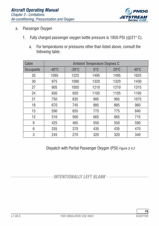
a. Passenger Oxygen
1. Fully charged passenger oxygen bottle pressure is 1850 PSI (@21° C).
Dispatch with Partial Passenger Oxygen (PSI) Figure 2.4.2
a. For temperatures or pressures other than listed above, consult the following table:
Occupants -40°C -20°C 0°C 20°C 40°C
35 1095 1225 1495 1495 1625
30 975 1090 1320 1320 1430
27 905 1005 1210 1210 1315
24 830 920 1105 1105 1195
21 750 835 995 995 1075
18 670 745 885 885 960
15 590 655 775 775 840
12 510 560 665 665 715
9 425 465 550 550 590
6 335 370 435 435 470
3 245 270 320 320 340
Cabin Ambient Temperature Degrees C
· INTENTIONALLY LEFT BLANK ·

FOR SIMULATOR USE ONLY 04SEPT09v.1.00.0
20
A. Battery
Chapter 3 - LimitationsElectrics and Lights
Aircraft Operating Manual
Electrics and Lights
1. An internal battery start of an engine must not be attempted if the battery busbars are less than 24.0 volts.
2. The charging current to each battery must be less than 45 amps before takeoff.
B. Ground Power Unit
1. The ground power switch must not be switched to ON unless the ground power voltage is within 27.5 - 29 volts.
a. Current for a ground power start:
1. Minimum continuous: 550 amps.
2. Maximum limit ranges: 1,500-2,000 amps.
C. Standby Compass
1. When reading the standby compass, the electrical services/systems ope-rating must correspond to those listed on the compass deviation card.
D. Generators
a. Ground Operations
1. The maximum continuous load for each generator on the ground is 400 amps.
NOTE:
This limit may be exceeded when the generator of the operating engine is used to assist the internal batteries in starting the second engine.
· INTENTIONALLY LEFT BLANK ·

FOR SIMULATOR USE ONLY 04SEPT09v.1.00.0
21
Chapter 3 - LimitationsElectrics and Lights
Aircraft Operating Manual
b. Maximum Load Prior to a Generator-Assisted Start
1. Generator-assisted start 300 amps.
c. Flight Operations
1. The maximum continuous load for each generator as charted on the graph below: in flight is 550 amps, or:
Air Temp Limitations Figure 2.5.1
STATIC AIR TEMPERATURE - °C
PRES
SURE
ALT
ITUD
E - F
T (X
100
0)
30
25
20
15
10
5
0
-5-60 -50 -40 -30 -20 -10 0 10 20 30 40 50 60
MIN
IMUM
AIR
TEM
PERA
TURE
MAXIM
UM AIR TEM
PERATURE ISA + 40°C
490A510A530A550A

FOR SIMULATOR USE ONLY 04SEPT09v.1.00.0
22
A. Engines And Propellers
Chapter 3 - LimitationsEngines and Propellers
Aircraft Operating Manual
Engines and Propellers
a. Engines
1. Allied Signal
a. Left TPE 331-14GR-802H
b. Right TPE 331-14HR-802H
b. Propellers
1. McCauley
a. Left B5JFR36C1 101-B/C-i 14GCA-0
b. Right C5JFR36C1 101-B/C-i 14GCA-0
B. Engines
a. Ground Starting
1. Starter generator duty cycles:
Start # Max Time On Rest1 1 minute 3 minutes2 1 minute 3 minutes3 1 minute 30 minutes
· INTENTIONALLY LEFT BLANK ·

FOR SIMULATOR USE ONLY 04SEPT09v.1.00.0
2�
Chapter 3 - LimitationsEngines and Propellers
Aircraft Operating Manual
b. Exhaust Gas Temperature (EGT)
1. An engine start must not be attempted if the residual EGT is greater than 200°C. A ventilation run may be continued directly into a manual engine start when the EGT has decreased to 200°C, or 15% RPM is reached, whichever occurs first.
2. The maximum permissible EGT during a start is 770°C.
c. Ventilation Run
1. Must not exceed 15 seconds or 15% RPM
d. Takeoff Operations with Reduced Torque
1. The reduced torque setting may not be less than 75%.
2. Reduced torque takeoffs are not permitted with APR armed.
3. Reduced torque takeoffs are not permitted with a tailwind.
4. Reduced torque takeoffs are not permitted on wet or contaminated run-ways.
5. Reduced torque takeoffs are not permitted where maximum performance is required, for example:
a. Wake turbulence
b. Windshear
6. Reduced torque takeoffs are not permitted when a non-standard takeoff procedure is used (e.g., low visibility takeoff).
7. Reduced torque takeoffs are not permitted when there is an inoperative item that affects performance or performance indication (e.g., anti-skid mop).
8. Reduced torque takeoffs are not permitted on first flight of the day.

FOR SIMULATOR USE ONLY 04SEPT09v.1.00.0
24
Chapter 3 - LimitationsEngines and Propellers
Aircraft Operating Manual
e. Takeoff and Maximum Continuous Power
1. The maximum permissible EGT at all times, other than engine start on the ground or in flight, is the displayed EGT LIMIT with the Integrated Elec-tronic Control (IEC) selected ON.
2. The maximum permissible EGT appropriate to the RPM and ambient conditions with both Integrated Electronic Controls (IECs) selected OFF is given in the Quick Reference Handbook (QRH).
3. Maximum continuous torque: 100%
4. The torque meter is calibrated on the basis of 100% torque being equal to 1500 SHP (shaft horsepower) at 100% engine rotation speed.
f. Automatic Performance Reserve (APR)
1. Both Integrated Electronic Control (IEC) computers must be selected ON and be operative before arming the APR system.
2. The TTL (torque and temperature limiter) system must be operational before arming the APR.
3. The APR system must not be used with an inoperative IEC computer.
4. A takeoff with the APR system armed must be made at, or greater than, the minimum takeoff torque setting obtained for the actual ambient condi-tions (no reduced power takeoffs with APR armed).
5. The APR override switch must only be operated as stated in the Engine Failure on Takeoff Profile or Single Engine Go Around/Missed Approach Profile.
6. APR system operating periods must not exceed 5 minutes -40°C
g. Relight In Flight
1. The maximum permissible EGT during a relight is 770°C.
FOR SIMULATOR USE ONLY 04SEPT09v.1.00.0
2�
Chapter 3 - LimitationsEngines and Propellers
Aircraft Operating Manual
h. Engine Instrument Color Coding
1. Maximum and minimum limits are marked with red radials.
2. Precautionary ranges are marked with a yellow arc or a yellow line.
3. Normal operating ranges are marked with a green arc.
i. Oil Temperatures
1. Minimum for starting
2. Maximum continuous: 110°C
3. Maximum (5-minute limit): 127°C
4. Minimum oil temperature for all operating conditions, except for startingand ground operations with condition levers at taxi RPM, is 50°C.
j. Oil Pressures
Minimum Pressure Maximum Pressure
1. Taxi RPM 30 PSI 65 PSI
2. Flight RPM 45 PSI 65 PSI
3. If the oil temperature is cold, a transient oil pressure of 85 PSI is permit-ted during engine start.
4. With the condition levers at taxi and reverse selected, the associated oil pressure is permitted to fall to a minimum of 20 PSI for a maximum of 10 seconds.
k. Engine Rotational Speeds
1. The maximum permissible engine rotational speed for normal operation is 101% RPM
a. This speed may be momentarily exceeded during the takeoff run, or for the purpose of carrying out overspeed governor checks.

FOR SIMULATOR USE ONLY 04SEPT09v.1.00.0
2�
Chapter 3 - LimitationsEngines and Propellers
Aircraft Operating Manual
l. RPM Operating Limits
1. 101% - Continuous
2. 101 to 105% - 30 seconds
3. 105 to 106% - 5 seconds
4. 106% - Never exceed
m. Malfunctioning Engine
1. If a malfunctioning engine is to be kept running at a reduced power set-ting as a precautionary measure:
a. The torque for that engine will be set at no less than 15% for the remainder of the flight.
· INTENTIONALLY LEFT BLANK ·

FOR SIMULATOR USE ONLY 04SEPT09v.1.00.0
2�
Chapter 3 - LimitationsEngines and Propellers
Aircraft Operating Manual
C. Propeller
WARNING: Movement of the power levers behind the flight idle stop is prohibited in flight.
1. Movement of any power lever behind flight idle stop while in flight will lead to a hazardous condition and loss of control from which recovery may not be possible.
2. Continuous operation between 82% and 90% RPM is prohibited.
3. Except for takeoff, continuous ground operation is prohibited above 60% torque in winds greater than 15 kts, unless the wind is from within +/- 45 degrees of the nose of the aircraft.
a. Windmilling RPM
1. 0 to 20% - Continuous
2. Greater than 20% - Not recommended
b. Minimum permissible RPM
1. Ground Idle - 72% RPM
2. In Flight - 96% RPM
3. Takeoff - 100% RPM
NOTE: 100% propeller shaft speed is equal to 1,552 RPM.
· INTENTIONALLY LEFT BLANK ·

FOR SIMULATOR USE ONLY 04SEPT09v.1.00.0
2�
A. Specifications
Chapter 3 - LimitationsFuel
Aircraft Operating Manual
Fuel
1. The fuel used must meet the latest approved issue of the following speci-fications.
a. Grade
1. Kerosene
b. Specification
1. JET A ,JET A-1, JP-8, CAN-M86
B. Fuel Pressures
1. The permissible fuel pressures:
a. Maximum 65 PSI
b. Motive flow 40 PSI
c. Standby pump 20 PSI
d. Minimum 10 PSI
C. Fuel Tank Temperatures
1. Minimum - 37°C
2. Maximum +49°C
· INTENTIONALLY LEFT BLANK ·

FOR SIMULATOR USE ONLY 04SEPT09v.1.00.0
29
Chapter 3 - LimitationsFuel
Aircraft Operating Manual
D. Fuel Management
1. Total usable fuel in each tank - 2,909 lbs.
2. Total usable fuel - 5,818 lbs
3. Maximum fuel imbalance (takeoff and landing) - 200 lbs.
4. The maximum fuel imbalance permitted for any phase of flight other than takeoff and landing - 500 lbs.
5. The fuel cross-feed valve must be selected to SHUT for takeoff and lan-ding.
6. If a fuel contents gauge indicates zero, any fuel remaining in the fuel tank cannot be safely used in flight.
· INTENTIONALLY LEFT BLANK ·
E. Standby Pumps
1. Must be turned ON for:
a. Engine start
b. Cross-feed
c. Motive flow failure
F. Refueling/Defueling
1. The maximum permissible fuel pressure or fuel flow for refueling is 50 PSI or 72 US gal/min.
2. The maximum permissible fuel pressure for defueling is -11 PSI.

FOR SIMULATOR USE ONLY 04SEPT09v.1.00.0
�0
A. Hydraulic Fluid
Chapter 3 - LimitationsHydraulics And Landing Gear
Aircraft Operating Manual
Hydraulics And Landing Gear
1. Specifications
a. USA specification MIL-H-5606
1. Hydraulic Pressure
a. Normal pressure 2,000 PSI
b. Maximum permissible pressure 2,450 PSI
B. Anti-skid
1. Anti-skid system must be on for takeoff and landing if it is operational If the system is deferred, refer to the Airport Analysis for any weight penal-ties to be applied.
C. Aircraft Pushback
1. Never have a tow bar attached to the aircraft while an engine(s) is run-ning. The aircraft will have to be repositioned, the tow bar removed, then the engine(s) may be started.
· INTENTIONALLY LEFT BLANK ·

FOR SIMULATOR USE ONLY 04SEPT09v.1.00.0
�1
A. Snow, Frost And Ice
Chapter 3 - LimitationsIce And Rain Protection
Aircraft Operating Manual
Ice And Rain Protection
1. The aircraft must be clear of snow, frost and ice before takeoff.
B. Slush/Standing Water/Snow
1. The aircraft is authorized to operate in accordance with the data as pub-lished in the Flight Operations Manual.
C. Icing Conditions Defined
1. Icing conditions exist when the outside air temperature (OAT) on the ground is 5°C or colder and visible moisture in any form is present (e.g., cloud, fog, or mist with visibility of one mile or less, rain, snow, sleet or ice crystals).
2. Icing conditions exist when the total air temperature (TAT) in flight is 10°C or colder, and visible moisture in any form is present (e.g., cloud, fog, or mist with visibility of one mile or less, rain, snow, sleet or ice crystals).
3. Icing conditions exist when the OAT on the ground is 5°C or colder when operating on ramps, taxiways or runways, where surface snow, ice, standing water, or slush may be ingested by the engines, or freeze on engines, nacelles, or engine-sensor probes.
4. Icing conditions exist when there are visible signs of ice accretion on the aircraft, or when the (amber) caption is on.ICE
DETECT
D. Airframe Ice Protection
1. Airframe deicing must not be activated during takeoff and below 200 ft. AGL on the approach to landing.
WARNING: Flight in icing conditions must be avoided if there is a known failure of the airframe deicing boots to inflate correctly.

FOR SIMULATOR USE ONLY 04SEPT09v.1.00.0
�2
E. Takeoff In Icing Conditions
Chapter 3 - LimitationsIce And Rain Protection
Aircraft Operating Manual
1. The aircraft must be clear of all deposits of snow, ice and frost adhering to the surfaces immediately before takeoff.
2. When actual or forecast icing conditions exist at or below 1,600 ft., the takeoff must be carried out with:
a. APR set to - ARM
b. Engine anti-icing - ON
c. Flow selectors - OFF
d. IGNITION - CONTINUOUS
F. Propeller And Engine/Elevator Ice Protection
1. Propeller and Engine/Elevator anti-icing must be switched ON during all ground and flight operations when in icing conditions and/or potential icing conditions are anticipated.
2. Propeller Anti-ice:
a. Temperatures -5°C or warmer SHORT CYCLE
b. Temperatures colder than -5°C LONG CYCLE
3. Except for testing or when activating for takeoff, propeller and engine/elevator anti-icing must be switched OFF on the ground when the OAT or TAT is warmer than 5°C.
4. Propeller and Engine/Elevator anti-icing must be switched OFF on the ground when the applicable engine/propeller is not running.
5. Engine Anti-ice test is limited to 10 seconds if temperature is greater than 10°C.
· INTENTIONALLY LEFT BLANK ·

FOR SIMULATOR USE ONLY 04SEPT09v.1.00.0
��
G. Landing In Icing Conditions
Chapter 3 - LimitationsIce And Rain Protection
Aircraft Operating Manual
1. A touch-and-go landing is not permitted with accreted ice on the aircraft.
· INTENTIONALLY LEFT BLANK ·
H. Continuous Ignition
1. If flight in heavy precipitation such as rain, hail or snow can not be avoi-ded, the engine IGNITION switches must be selected to CONTINUOUS.
2. If taking off or landing on a contaminated runway, the engine IGNITION switches must be selected to CONTINUOUS.
FOR SIMULATOR USE ONLY 04SEPT09v.1.00.0
�4
A. General
Chapter 3 - LimitationsAvionics
Aircraft Operating Manual
Avionics
1. The AVIONICS MASTER must be selected to OFF during any engine start or engine shutdown on the ground.
2. The AHRS takes 3 minutes to run up and 15 minutes to run down. The aircraft must not be moved during these times or damage may occur to the gyros.
B. Flight Director
1. The flight director (FD) must not be used in the following conditions:
a. As sole means of reference to the required flight path.
b. For guidance below a height of 200 ft. above the runway thresh-old when coupled to a precision approach.
2. The FD must be at SBY, or GA, or GA and HDG, or GA, HDG and ALT SEL for takeoff if the FD will be used during the takeoff.
NOTE:
The GNS-XLS may generate misleading information during non-precision GPS approaches due to software limitations.
C. GNS-XLS Flight Management System
1. During periods when the DR warning is illuminated, navigation shall not be predicated on the FMS.
2. The GNS-XLS is not approved for non-precision approaches.
· INTENTIONALLY LEFT BLANK ·

FOR SIMULATOR USE ONLY 04SEPT09v.1.00.0
��
Chapter 3 - LimitationsAvionics
Aircraft Operating Manual
D. Traffic Alert And Collision Avoidance System (TCAS)
1. The Traffic Alert and Collision Avoidance System (TCAS) must be used for advisory purposes only.
2. TCAS must not be used when the TCAS fail annunciators on either EHSI and EADI display are illuminated, or after failure of any of the following systems:
a. Encoding altimeter
b. Radio altimeter
c. AHRS inputs to TCAS
d. Mode S transponder
E. Autopilot And Yaw Damper
a. Speeds
1. When the auto-flight control system (AFCS) is engaged, the maximum permissible speed is Vmo at and below 17,400 ft. Above 17,400 ft., Mmo is the maximum permissible speed. The minimum permissible speed with the AFCS engaged is 1.3 Vs lAS.
b. Engagement
1. The AFCS must not be engaged:
a. During takeoff and landing.
b. When the automatic elevator trim system is inoperative.
c. At a height less then 500 ft. AGL, except when coupled to an ILS glideslope
d. During flight in icing conditions with the (amber) caption on.
e. In flight with severe icing visual cues present.
f. On the ground with the gust locks engaged.
ELEV

FOR SIMULATOR USE ONLY 04SEPT09v.1.00.0
��
Chapter 3 - LimitationsAvionics
Aircraft Operating Manual
2. The yaw damper must not be engaged:
a. During takeoff.
b. On the ground with the gust locks engaged.
c. During landing.
c. Coupled ILS approach and landing
1. The aircraft is approved for landing using either an approach with the flight director followed by a manual landing, or an autopilot coupled approach followed by a manual landing.
2. The autopilot must be disengaged at a height no lower than 200 ft. above TDZE or DH, whichever is higher.
d. Coupled ILS approach and landing with one engine inoperative
1. If an engine failure occurs during an ILS coupled approach, the AFCS must be disengaged and the aircraft manually re-trimmed in all axes, before the AFCS is re-engaged.
· INTENTIONALLY LEFT BLANK ·
FOR SIMULATOR USE ONLY 04SEPT09v.1.00.0
1
Table of Contents
Aircraft Operating ManualTable of Contents - Normal Procedures & Profiles
GENERAL 4-1-3
Normal Procedures & Profiles
A. Introduction 4-1-3B. Preparation And Planning Philosophy 4-1-3C. Flows & Checklists Philosophy 4-1-3D. Profile Philosophy 4-1-6E. Crew Coordination 4-1-6NORMAL CHECKLIST 4-2-10NORMAL PROCEDURES 4-3-12A. Aircraft Acceptance 4-3-12B. Exterior Preflight Inspection 4-3-14C. Security Inspections 4-3-20D. Cockpit Preparation 4-3-22E. Departure Preparation And Planning Duties 4-3-36F. Turn Check 4-3-42G. Final Departure Preparation 4-3-45H. Before Start Check 4-3-46I. Pushback Procedures 4-3-49J. Engine Start 4-3-50K. After Start 4-3-55L. Taxi Check 4-3-61M. Taxiing 4-3-66N. Departure 4-3-67O. Operation Of The SPZ-4500 Flight Director 4-3-70P. Takeoff Profile 4-3-71Q. After Takeoff 4-3-76

FOR SIMULATOR USE ONLY 04SEPT09v.1.00.0
2
Table of Contents
Aircraft Operating ManualTable of Contents - Normal Procedures & Profiles
Normal Procedures & Profiles (continued...)
R. Enroute Climb 4-3-78S. Cruise 4-3-80T. Holding Procedure 4-3-81U. Descent 4-3-82V. Descent And Approach Preparation And Planning 4-3-83W. General Approach Procedures 4-3-90X. Visual Approach Profile 4-3-91Y. Precision Approach Profile 4-3-94Z. Non-precision Approach Profile 4-3-98AA. Circling Approach Profile 4-3-103BB. Landing Check 4-3-105CC. Landing Profile 4-3-106DD. After Landing 4-3-109EE. Single-engine Shutdown 4-3-112FF. Shutdown 4-3-114GG. Post Flight Duties 4-3-117HH. Securing 4-3-118II. Go-aroundimissed Approach 4-3-120JJ. Two Engine Missed Approach Profile 4-3-123
· INTENTIONALLY LEFT BLANK ·

FOR SIMULATOR USE ONLY 04SEPT09v.1.00.0
A. Introduction
Chapter 4 - Normal Procedures & ProfilesGeneral
Aircraft Operating Manual
�
General
1. This chapter contains directions for the accomplishment of Preparation and Planning, Flows, Checklists, and Profiles for normal operations. This chapter provides the basic information necessary to operate the aircraft during a normal flight. The information herein is presented in a normal flight sequence.
B. Preparation And Planning Philosophy
1. Preparation and Planning procedures are duties that do not fit into a specific Flow or Profile. They include preflight and in-flight duties, such as getting the ATIS, reviewing the release, getting the clearance, performance calculations, Pax briefings, approach briefings, etc. Preparation and Plan-ning duties are performed when appropriate, considering the phase of flight and expectations of how the flight will progress.
2. Critical items that are part of Preparation and Planning duties are included in various checks to verify they have been completed.
C. Flows & Checklists Philosophy
1. Most procedures are accomplished by a Flow-Check combination. After a flow is completed, the checklist will serve to verify critical items/proce-dures have been accomplished.
a. A flow pattern is the stringing together of items to be performed in a logical order to increase efficiency. Flows contain items that may not be subsequently challenged or checked by the checklist. All flow items are required actions that must be committed to, and performed by memory. Published flows must be performed in the exact order specified.
2. When used with a flow philosophy, all checked items will be completed prior to calling for the check, excluding ‘Do” checks (“Do” checks require the action be performed as the checklist is being read, as opposed to a flow-check).

FOR SIMULATOR USE ONLY 04SEPT09v.1.00.0
Chapter 4 - Normal Procedures & ProfilesGeneral
Aircraft Operating Manual
4
3. The checklist is intended to achieve the following:
a. Aid the pilots in recalling the process for configuring the aircraft.
b. Provide a standard foundation to verify aircraft configuration while defeat-ing any reduction in the flight crew’s psychological and physical condi-tion.
c. Provide convenient sequences for motor movements and eye fixations along the cockpit panels.
d. Provide a sequential framework to meet internal and external cockpit operational requirements.
e. Allow mutual supervision among crewmembers.
f. Promote a team concept for configuring the aircraft by keeping all crew-members involved.
4. Checks are either “silent” or “aloud”. During ground operations, the Cap-tain will call for all checks, and the First Officer (FO) will read all checks. During flight, the Pilot Flying (PF) will call for all checks and the Pilot Not Flying (PNF) will read all checks. When reading an “aloud” check, the crewmember(s) designated to respond to the challenge should visually confirm that the challenged action (switch position, instrument configura-tion, etc.) has been properly accomplished.
5. If a single response covers multiple items, the response will indicate that all required actions have been completed. Any action that has not been performed or completed when challenged must be completed before the next challenge is read.
6. When a check is complete, the pilot reading the check will state “CHECK COMPLETE”.
· INTENTIONALLY LEFT BLANK ·

FOR SIMULATOR USE ONLY 04SEPT09v.1.00.0
Chapter 4 - Normal Procedures & ProfilesGeneral
Aircraft Operating Manual
�
7. The description of each check is laid out (unless otherwise indicated) by the flow for each pilot, as well as the activities to be conducted at each step in the flow, then the check, and if necessary, an expanded check for those items not previously explained by the flow. Typical layout:
a. Flow 1st.
b. Check 2nd.
c. Expanded check (if not previously explained) 3rd.
8. Checklist items printed in all CAPITAL LETTERS must be read aloud. Items in lower case letters will be read silently.
9. Checklist Items indented with + are accomplished on the aircraft’s first flight of the day only.
10. The following is a list of abbreviations for the pilot who will make the response to a challenge:
a. CAPTAIN ........................ C
b. FIRST OFFICER .............. F
c. PILOT FLYING ................. PF
d. PILOT NOT FLYING ......... PNF
e. BOTH ............................. B
(1) On a “Both” response, the pilot reading the check will respond second.
· INTENTIONALLY LEFT BLANK ·

FOR SIMULATOR USE ONLY 04SEPT09v.1.00.0
D. Profile Philosophy
Chapter 4 - Normal Procedures & ProfilesGeneral
Aircraft Operating Manual
�
1. The described profiles are to be performed in training and line operations. Small deviations from these profiles may be required during some opera-tions since it is impossible to envision all possible scenarios when scripting profiles.
2. Many of the profiles are described by stating Flight Director (FD) modes. The PF will follow the FD when it is properly set up. If the FD is inoperative, the actual flight path and speeds flown will be the same as if the FD was operative. It is understood that Flight Control Panel/Flight Director (FCP/FD) selection calls need not be made if the FD is inoperative.
E. Crew Coordination
1. Throughout all normal procedures, even when not specifically written, crewmembers will monitor the airplane systems through periodic checks of the various instruments, displays and circuit breaker panels.
2. If the Autopilot (AP) is not engaged, the PNF will make all FCP/FD selec-tions at the request of the PF. In cases where the PNF is occupied with other essential duties, the PF may make simple FCP/FD selections.
3. If the AP is engaged, the PF will make his own FCP/FD selections In high workload situations, the PF may ask the PNF to make the selection for him.
4. When calling for FCP selections, the PF will state the title of the button he wants pushed.
a. Heading Changes
a) Autopilot Off:
(1) The PNF will set heading changes issued by ATC The PNF will enter the new heading while reading it back to ATC Once the new heading is entered, the PNF will state the new heading, followed by verbal confirmation by the PF.

FOR SIMULATOR USE ONLY 04SEPT09v.1.00.0
Chapter 4 - Normal Procedures & ProfilesGeneral
Aircraft Operating Manual
�
(a) Example:
(i) ATC issues a heading of 230°.
(ii) The PNF enters the 230° heading while reading it back and once the heading is entered, states “230”.
(iii) The PF verifies the correct heading and states, “230”.
b) Autopilot On:
(1) The PF will set heading changes issued by ATC. The PF will enter the new heading while the PNF reads it back to ATC. Once the new heading is set, the PF will state the new heading, followed by verbal confirmation by the PNF.
(a) Example:
(i) ATC issues a heading of 230°.
(ii) The PF enters the 230° heading and, once the heading is entered, states, “230”.
(iii) The pilot not flying reads the heading back to ATC, verifies the proper heading and states, “230”.
b. Altitude Changes
a) Autopilot Off:
(1) The PNF will set any altitude change issued by ATC. The PNF will enter the new altitude clearance while reading it back to ATC. Once the new altitude is entered, the PNF will restate the altitude new clearance and point at the altitude displayed until a verbal confirma-tion is received from the PF.
· INTENTIONALLY LEFT BLANK ·

FOR SIMULATOR USE ONLY 04SEPT09v.1.00.0
Chapter 4 - Normal Procedures & ProfilesGeneral
Aircraft Operating Manual
�
(a) Example:
(i) ATC issues an altitude of 8000’
(ii) The PNF enters 8000’ in the altitude preselector while read-ing it back. The PNF then points to the preselect display and states, “Eight Thousand”.
(iii) The PF verifies the correct altitude and states, “Eight Thou-sand”.
b) Autopilot On:
(1) The PF will set any altitude change issued by ATC. The pilot flying will enter the new altitude clearance while the PNF reads it back to ATC. Once the new altitude is entered, the PF will state the new clearance altitude and point at the display until a verbal confirmation is received from the PNF.
(a) Example:
(i) ATC issues an altitude of 8000’.
(ii) The PF enters 8000’ in the altitude preselector while the PNF reads it back. The PF then points to the preselect display and states, “Eight Thousand”.
(iii) The PNF verifies the correct altitude and states, “Eight Thou-sand”.
c. FMS Entries
1) While taxiing, the FO will make all FMS entries.
2) At or below 10,000 feet (not in cruise), the PNF should make all FMS entries. In cases where the PNF is occupied with other essen-tial duties, the PF may make simple FMS selections.
3) Above 10,000 feet or in cruise flight below 10,000 ft, the PF may make FMS entries when workload permits.
FOR SIMULATOR USE ONLY 04SEPT09v.1.00.0
Chapter 4 - Normal Procedures & ProfilesGeneral
Aircraft Operating Manual
9
d. Transfer of Control
1) The following procedure will be used when transferring controls from one crewmember to the other:
(i) The pilot transferring the flight controls will brief the direction (heading or course), altitude and any other pertinent informa-tion (e.g., crossing restriction, airspeed restriction, clearance limit, etc.), and state, “You have the controls”.
2) The pilot accepting the flight controls will state, “I have the controls”.
e. Comm Radio Management
1) The Comm 1 radio will normally be used for ATC communications. The PF will always monitor Comm 1. The PNF will monitor Comm 1 and perform ATC communication duties except when other duties interfere (e.g., getting the ATlS, in range calls, PAX briefings, etc.)
2) Whenever the PNF stops monitoring ATC, he will inform the PF by stating, “I’m off one”. The PF will acknowledge by stating, “I have one” and will assume ATC communication duties. When the PNF resumes ATC communication duties, he will state, “Back on one”. The PF will advise the PNF of any changes that have occurred while the PNF was not monitoring Comm 1. If no changes occurred, the PF will state, “No changes”.
f. Navigational Charts
1) For ground, departure and arrival operations, both pilots will have the appropriate chart in use.
2) In cruise, at least one pilot will have a chart open to the appropriate area and available for immediate use.
· INTENTIONALLY LEFT BLANK ·
FOR SIMULATOR USE ONLY 04SEPT09v.1.00.0
10
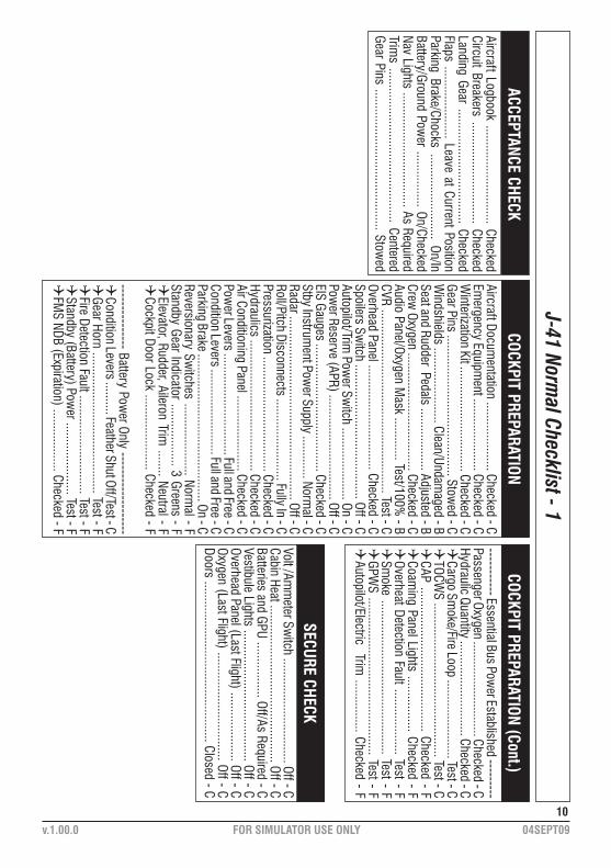
J-41 Normal Checklist - 1
ACCEPTANCE CHECKAircraft Logbook .............................. CheckedCircuit Breakers ............................... CheckedLanding Gear ................................... CheckedFlaps ...................... Leave at Current PositionParking Brake/Chocks .......................... On/InBattery/Ground Pow
er ................. On/CheckedNav Lights ................................... As RequiredTrim
s ............................................... CenteredGear Pins ........................................... Stow
ed
COCKPIT PREPARATION
Volt /Amm
eter Switch ................................ Off - C
Cabin Heat ................................................ Off - CBatteries and GPU ................. Off/As Required - CVestibule Lights ........................................ Off - COverhead Panel (Last Flight) ..................... Off - COxygen (Last Flight) ................................. Off - CDoors ................................................. Closed - C
Aircraft Documentation ..................... Checked - C
Emergency Equipm
ent ...................... Checked - CW
interization Kit ................................ Checked - CGear Pins ........................................... Stow
ed - CW
indshields ....................... Clean/Undamaged - B
Seat and Rudder Pedals ................... Adjusted - BCrew
Oxygen .................................... Checked - CAudio Panel/Oxygen M
ask ............. Test/100% - B
CVR ........................................................ Test - COverhead Panel ................................ Checked - CSpoilers Sw
itch ......................................... Off - CAutopilot/Trim
Power Sw
itch ...................... On - CPow
er Reserve (APR) ................................ Off - CEIS Gauges ....................................... Checked - CStby Instrum
ent Power Supply ............. Norm
al - CRadar ........................................................ Off - CRoll/Pitch Disconnects ......................... Fully In - CPressurization ................................... Checked - CHydraulics ........................................ Checked - CAir Conditioning Panel ....................... Checked - CPow
er Levers ............................... Full and Free - CCondition Levers .......................... Full and Free - CParking Brake ............................................. On - CReversionary Sw
itches ...................... Normal - F
Standby Gear Indicator ................... 3 Greens - FQ
Elevator, Rudder, Aileron Trim ........ Neutral - F
QCockpit Door Lock ....................... Checked - F
--------------- Battery Power Only -------------------
QCondition Levers .......... Feather Shut Off/Test - CQ
Gear Horn ........................................... Test - FQ
Fire Detection Fault .............................. Test - FQ
Standby (Battery) Power ...................... Test - F
QFM
S NDB (Expiration) ................... Checked - F
COCKPIT PREPARATION (Cont.)----------- Essential Bus Pow
er Established ---------Passenger Oxygen ............................. Checked - CHydraulic Quantity ............................. Checked - C Q
Cargo Smoke/Fire Loop ........................ Test - C
QTOCW
S ............................................... Test - CQ
CAP ............................................ Checked - FQ
Coaming Panel Lights ................. Checked - F
QOverheat Detection Fault .................... Test - FQ
Smoke ............................................... Test - F
QGPW
S ................................................ Test - FQ
Autopilot/Electric Trim ................ Checked - F
SECURE CHECK

FOR SIMULATOR USE ONLY 04SEPT09v.1.00.0
11
J-41 Normal Checklist - 2
TURN CHECKQ
PREFLIGHT BRIEF .................... COMPLETE - B
EXTERNAL CHECK ....................... COMPLETE - B
PRESSURIZATION .................................... SET - CCABIN SIGNS ............................................ ON - COXYGEN ......................................... CHECKED - BCARGO SM
OKE/FIRE .............................. TEST - CPARKING BRAKE ....................................... ON - CCLEARANCE BRIEF ....................... COM
PLETE - BFM
S/RADIOS ........................................... SET - B“TURN CHECK COM
PLETE”
BEFORE START CHECKAIRCRAFT LOG/RELEASE ............... CHECKED - CGEAR PINS ...................................... STOW
ED - CBEACONS/NAVS ....................................... ON - CFUEL .........................._______LBS CHECKED - BDOORS/REFUEL ................................ CLOSED - CBATTERIES ................................................ ON - C
“BEFORE START CHECK COMPLETE”
AFTER START CHECKEM
ERGENCY LIGHTS ....................... ARMED - F
SPOILERS .......................................... ARMED - C
APR .............................................. ________ - CQ
ICE PROTECTION ............................ TEST - FQ
STALL SYSTEM ............................... TEST - F
“AFTER START CHECK COMPLETE”
START LOCK(S) ............................ REMOVED - C
FLAPS ...................... 9 SET AND INDICATING - BTRIM
S ............................ GREEN & _______ - B
CAP ...................... UNDERSTOOD/UNMUTED - B
INSTRUMENTS ..........._____._____CHECKED - B
TAKEOFF DATA ............................... _____SET - BTAKEOFF BRIEF .............. _______COM
PLETE - BFLIGHT ATTENDANT ........................ ADVISED - F
“TAXI CHECK COMPLETE”
TAXI CHECK
DEPARTURE CHECKAFTER LANDING CHECK
FLIGHT CONTROLS ............................... FREE - BTOCW
S ................................................ TEST - FTRANSPONDER ....................................... ON - FTHE LINE ____________________________ - CIGNITION/ANTI-ICE .............................. _____ - CFLOW
S ............................................... _____ - FCONDITION LEVERS .......................... FLIGHT - F
“DEPARTURE CHECK COMPLETE”
AFTER TAKEOFF CHECKLanding Gear ......................................... UP - PNFFlaps ..................................................... UP - PNFAPR .................................................... OFF - PNFFlow
s .............................................. _____ - PNFLights .................................................. OFF - PNFCondition Levers .......................... 96-100%
- PNFProp Sync ............................................. ON - PNF
“AFTER TAKEOFF CHECK COMPLETE”
ALTIMETERS .............. ____.____ - CHECKED - B
FLIGHT ATTENDANT .................... ADVISED - PNFPRESSURIZATION .............................. SET - PNFSPOILERS ..................................... ARM
ED - PNFFUEL BAL/X-FEED ............ IN LIM
ITS/SHUT - PNFAPR .................................................. ARM
- PNFICE AOA ...................................... ______ - PNFLANDING DATA ................................. SET - PNFARRIVAL BRIEF ........................... COM
PLETE - BAPPROACH BRIEF ....................... COM
PLETE - B“DESCENT/APPROACH CHECK COM
PLETE”
DESCENT/APPROACH CHECK
LANDING CHECKLANDING GEAR ........ DOW
N FOR RWY_____ - B
FLAPS ....... ______SET AND INDICATING - PNFCONDITION LEVERS ................... FLIGHT - PNFFLOW
S ........................................ THREE - PNFFLIGHT ATTENDANT ................ ADVISED - PNF
“LANDING CHECK COMPLETE”
Spoilers .................................................. OFF - FGust Locks ................................... ENGAGED - FFlaps ....................................................... UP - FTransponder .................................. STANDBY - F
“AFTER LANDING CHECK COMPLETE”
SHUTDOWN CHECK
Parking Brake ........................................... ON - FRight Console ......................................... OFF - FFlow
s ...................................................... OFF - FEm
ergency Lights ................................... OFF - FAvionics M
asters .................................... OFF - FGenerators .............................................. OFF - FSeat Belt Sign ......................................... OFF - FBeacons ................................................. OFF - FAFIS Closeout .............................. TRANSM
IT - F“SHUTDOW
N CHECK COMPLETE,
DEBRIEF ITEMS”
Landing Gear ........................................ UP - PNFFlaps .................................................... UP - PNFLights ................................................. OFF - PNFLanding Data ...................................... SET - PNFCondition Levers ......................... 96-100%
- PNFALTIM
ETERS .............. ____.____ - CHECKED - B FUEL .............................................. CHECKED - BARRIVAL BRIEF ........................... COM
PLETE - BAPPROACH BRIEF ....................... COM
PLETE - BPASSENGER BRIEF .................. COM
PLETE - PNF“GO
-AROUND MISSED APPROACH CHECK
COMPLETE”
Returning to the same airport, landing check next.
Diverting to a different airport, after takeoff check next. GO
-AROUND MISSED APPROACH
CHECK

FOR SIMULATOR USE ONLY 04SEPT09v.1.00.0
A. Aircraft Acceptance
Chapter 4 - Normal Procedures & ProfilesAircraft Acceptance
Aircraft Operating Manual
12
Normal Procedures
1. The Acceptance Check is performed by either crewmember prior to power up, when receiving an aircraft, or after maintenance has been accom-plished It is completed silently.
a) Aircraft Logbook ..................... Checkedb) Circuit Breakers ...................... Checkedc) Landing Gear .......................... Downd) Flaps ...................................... Leave at Current Positione) Parking Brake/Chocks ............. On/Inf) Battery/Ground Power ............. On/Checkedg) Nav Lights .............................. As Requiredh) Trims ...................................... Centeredi) Gear Pins ............................... Stowed
a. Acceptance Check
b. Acceptance Check Expanded
a) Aircraft Logbook ..................... Checked
(i) Check the aircraft logbook lAW the AOM.
b) Circuit Breakers ...................... Checked
(i) All circuit breakers should be checked to ensure they are in. If a circuit breaker is pulled in relation to a deferred maintenance item, it should be collared and in compliance with the MEL.
(ii) When a circuit breaker trips during ground operations, it may only be reset in accordance with the Circuit Breaker Reset Policy contained within the AOM.
FOR SIMULATOR USE ONLY 04SEPT09v.1.00.0
Chapter 4 - Normal Procedures & ProfilesAircraft Acceptance
Aircraft Operating Manual
1�
c) Landing Gear .......................... Down
(i) The gear handle should be in the gear down position.
d) Flaps ...................................... Leave at Current Position
(i) Put the flap lever in the position that corresponds to the actual flap position.
e) Parking Brake/Chocks ............. On/In
(i) Ensure that the parking brake is set and the pressure is at least 750 PSI. If the pressure is less than 750 PSI, chocks must be installed before engine start.
(ii) Hydraulic pressure may be increased by “spinning” a propel-ler.
(iii) If boarding passengers, the wheels must be chocked.
f) Battery/Ground Power ............. On/Checked
(i) Select the ammeter to battery and ensure adequate battery voltage, then select the battery master switches to ON. If a GPU is available, select the ammeter to GPU and ensure that 27.5-29 volts are available prior to selecting the GPU to ON.
g) Nav Lights .............................. As Required
(i) If GPU is available or as battery charge permits, select the NAV lights ON.
h) Trims ...................................... Centered
(i) Center the elevator, rudder and aileron trim indicators prior to preflight inspecting the aircraft.
i) Gear Pins ............................... Stowed
(i) Ensure all three gear pins are stowed in the holder beside the Captain’s seat.

FOR SIMULATOR USE ONLY 04SEPT09v.1.00.0
B. Exterior Preflight Inspection
Chapter 4 - Normal Procedures & ProfilesExterior Preflight Inspection
Aircraft Operating Manual
14
1. The exterior preflight is a visual inspection of the aircraft that ensures the airplane condition is acceptable for flight The preflight inspection will be performed anytime the crew accepts a new aircraft. It is normally per-formed by the FO. However, it is encouraged but not required, that the Captain do a short walk-around inspection after the FO has completed the initial preflight This is a simple way to check and verify your partners work.
2. The preflight starts at the forward door of the aircraft and progresses in a clockwise manner to the nose, right wing, empennage, left wing and then ends at the forward door.
3. While conducting the inspection, check the proximate area for potential FOD items and unusual obstructions.
4. The airplane and its visible components must be checked for damage and general condition, evidence of leaks, and as specified below:
a) Passenger Door
(i) Check condition of the door seal and the door restraining cable. Observe movement and dampening during lowering of passenger door. Lift the speed lock release cover and ensure that the speed lock lanyard ring is visible.
b) Left Front Fuselage
(i) Ensure the Pitot/Static and TAT covers are removed and ports are clear of obstructions. Inspect AOA sensor. Check that the skin, antennas, ice detector probe and left windshield/wiper are unob-structed and undamaged.
c) Nosewheel
(i) Check that the nose gear pin is removed. Check that the gear doors, WOW switch and lights are clean/undamaged. Ensure that there are no hydraulic leaks. Inspect tires for proper inflation, obvious wear, cuts and scuffing. Ensure the gear doors are undamaged. Aircraft must be chocked prior to boarding passengers.

FOR SIMULATOR USE ONLY 04SEPT09v.1.00.0
Chapter 4 - Normal Procedures & ProfilesExterior Preflight Inspection
Aircraft Operating Manual
1�
d) Nosecone
(i) Check the nosecone for security and damage, and that the wind-shield washer reservoir cap is flush.
e) Right Front Fuselage
(i) Ensure the Pitot/Static covers are removed and ports are clear of obstructions. Inspect AOA sensor. Check that the skin, antennas, and right windshield/wiper are unobstructed and undamaged. Check the oxygen discharge indicator is intact and green.
f) Right Inboard Wing Leading Edge
(i) Check to see that the deicing boot is undamaged. Observe vortex generator vanes for condition and ensure none are missing (If any are, notify Maintenance, and refer to the CDL). Check the engine panels for security, and the general condition of nacelle for fluid leaks or damage.
g) Right Engine
(i) Ensure the engine intake and oil cooler plugs are removed and the intakes are clear of ice, snow or other contaminants. Check to see the vents and drains are clear and all of the nacelle panels are secure. Ensure that engine nacelle areas are checked for puddled or dripping fuel or oil. The ice observation light should be clean and undamaged.
h) Right Propeller
(i) Ensure the propeller is on the start lock, undamaged and free to rotate Inspect the compressor blades for damage.
(ii) Only rotate the propeller in the normal direction of rotation.
· INTENTIONALLY LEFT BLANK ·

FOR SIMULATOR USE ONLY 04SEPT09v.1.00.0
Chapter 4 - Normal Procedures & ProfilesExterior Preflight Inspection
Aircraft Operating Manual
1�
i) Right Wing Leading Edge
(i) Check to see the deicing boot is undamaged. Inspect the fuel ac-cess panel and ice depth gauge for condition and security.
j) Right Wing Tip and Trailing Edge
(i) Inspect the navigation, strobe and conspicuity lights for damage, cleanliness and security. Ensure there are no heat bubbles in lens cover. Check Ailerons and Flaps for condition and security. Ensure aileron mass balance tab is undamaged. Ensure the static wicks are installed (if any are missing refer to the MEL).
k) Right Wing Undersurface
(i) Inspect the wing undersurface for damage and ensure all panels are secure. Ensure fuel level indicators are secure and fuel vent is clean Check water drain valves for security.
l) Right Engine Trailing Edge
(i) Remove the exhaust cover and inspect pen nib for cracks. Visu-ally inspect rear turbine blades for damage. Inspect the rear turbine bearing cover for signs of oil leakage, and ensure its safety wire is in place. Ensure tail pipe is secure.
m) Right Main Landing Gear
(i) Check to see the main gear pin is removed. Inspect the main land-ing gear strut, gear linkage, brake lines, and brake wear indicators for condition, and that there are no fluid leaks. Check the gear doors are undamaged. Inspect the tires for proper inflation, wear, cuts and excess scuffing.
n) Right Inboard Trailing Edge
(i) Inspect wing fillet for security and that no cracks are evident. Check inboard flaps for condition and security.

FOR SIMULATOR USE ONLY 04SEPT09v.1.00.0
Chapter 4 - Normal Procedures & ProfilesExterior Preflight Inspection
Aircraft Operating Manual
1�
o) Right Aft Fuselage
(i) Check fuselage and cabin windows for condition. Check pod door operation. Inspect the interior of the pod for a proper seal around the battery doors. Check the interior perimeter of the pod door, including the hinge area for loose, missing or damaged foam seal-ant or gasket material. Close the pod door. Check both emergency exits for proper installation and security Check emergency exit light covers and inspection window for condition.
p) Empennage
(i) Inspect all control surfaces for damage and security. Inspect the deicing boots for damage. Check navigation lights, tail flood lights, antennas, vortex generators and static wicks (5) for condition.
q) Left Aft Fuselage
(i) Check the oxygen discharge indicator is intact and green. If the aft bag door is open, check the compartment for damage or cracks. Visually inspect the toilet servicing access panel for security. Check pod door operation. Inspect interior of pod for loose, missing or damaged sealant tape. Check the interior perimeter of the pod door, including the hinge area, for loose, missing or damaged foam seal-ant or gasket material. Close the pod door. Check all three fire bottle discharge indicators are intact and green. Open and Inspect the hydraulic reservoir sight glass for proper servicing and ensure the hydraulic panel is secured closed and there are no leaks. Check the over wing emergency exit for proper installation and security. Check emergency exit light covers for condition.
r) Left Inboard Trailing Edge
(i) Inspect wing fillet for security and that no cracks are evident. Check inboard flaps for condition and security.

FOR SIMULATOR USE ONLY 04SEPT09v.1.00.0
Chapter 4 - Normal Procedures & ProfilesExterior Preflight Inspection
Aircraft Operating Manual
1�
s) Left Engine Trailing Edge
(i) Remove exhaust cover and inspect pen nib for cracks. Visually inspect the rear turbine blades for damage. Inspect the rear turbine bearing cover for signs of oil leakage and ensure its safety wire is in place. Ensure the tail pipe is secure.
t) Left Main Landing Gear
(i) Check to see the main gear pin is removed. Inspect the main land-ing gear strut, gear linkage, brake lines, and brake wear indicators for condition, and that there are no fluid leaks. Check the gear doors are undamaged. Inspect the tires for proper inflation, wear, cuts and excessive scuffing.
u) Left Wing Undersurface
(i) Inspect the wing undersurface for damage and ensure all panels are secure. Ensure fuel level indicators are secure and fuel vent is clean.
v) Left Wing Tip and Trailing Edge
(i) Inspect the navigation, strobe and conspicuity lights for damage, cleanliness and security. Ensure there are no heat bubbles in lens cover. Check ailerons and flaps for condition and security. Ensure the aileron mass balance tab is undamaged, the aileron trim tab is neutral, and 4 static wicks are installed.
w) Left Wing Leading Edge
(i) Check the deicing boot for damage. Inspect the ice depth gauge for condition and security.
· INTENTIONALLY LEFT BLANK ·

FOR SIMULATOR USE ONLY 04SEPT09v.1.00.0
Chapter 4 - Normal Procedures & ProfilesExterior Preflight Inspection
Aircraft Operating Manual
19
x) Left Propeller
(i) Ensure the propeller is on the start lock, undamaged and free to rotate. Inspect the compressor blades for damage.
(ii) Only rotate the propeller in the normal direction of rotation.
y) Left Engine
(i) Ensure the engine intake and oil cooler plugs are removed and the intakes are clear of ice, snow or other contaminants. Check to see the vents and drains are clear and all of the nacelle panels are secure. Ensure that engine nacelle areas are checked for puddled or dripping fuel or oil. The ice observation light should be clean and undamaged.
z) Left Inboard Wing Leading Edge
(i) Check to see that the deicing boot is undamaged. Observe vortex generator vanes for condition and ensure none are missing. (If any are, notify Maintenance, and refer to the CDL.) Check the engine panels for security and general condition of nacelle for fluid leaks or damage.
aa) Under Fuselage Center Section
(i) Check the white strobe light for condition. Ensure the air cycle ma-chine inlets and outlets are unobstructed and outlets are secure.
· INTENTIONALLY LEFT BLANK ·

FOR SIMULATOR USE ONLY 04SEPT09v.1.00.0
C. Security Inspections
Chapter 4 - Normal Procedures & ProfilesSecurity Inspections
Aircraft Operating Manual
20
1. Perform the following security inspections as set forth by the policies in the AOM.
Wheel Wells .............................. InspectEngine Inlets,Exhaust ................ Clear And UnobstructedGPU Plug Access Door ............. Open and InspectAft Baggage ............................. Open and InspectPod .......................................... Open and InspectLavatory Service Panel ............. Open and Inspect
(Request Assistance of Ground Personnel)
Hydraulic Access Door ............. Open and InspectACM Inlets and Exhaust ............ Clear And UnobstructedLoose or Missing Doors / .........Panels
Notify MX and GSC
a. External Security Inspection
Aft Closet ...................................... Open and InspectAll Aft Storage Compartments ....... Open and InspectLavatory and Trash Bin .................. Open and InspectFirst Aid and Emergency Medical ... Kits
Inspect Seal
Seat Back Pockets ........................ Inspect ContentsEach Seat Cushion ........................ Remove and Inspect UndersideAll Seats ....................................... Inspect UnderGalley ........................................... Inspect All CompartmentsForward Right Closet ..................... Open and InspectWinterization Kit ............................ Open and Inspect ContentsForward Left Closet ....................... Open and Inspect
b. Interior Security Inspection

FOR SIMULATOR USE ONLY 04SEPT09v.1.00.0
Chapter 4 - Normal Procedures & ProfilesSecurity Inspections
Aircraft Operating Manual
21
Cockpit Crew Bag Stowage Areas ................. Open and InspectAll Stowage Compartments ........................... Open and InspectPilot Seats .................................................... Inspect Under and BehindLife Vest Storage Pouch ................................ Inspect ContentsArea Above and Behind Rudder Pedals .......... InspectSide Pouches and Storage Compartments ..... Inspect
c. Cockpit Security Inspection
· INTENTIONALLY LEFT BLANK ·

FOR SIMULATOR USE ONLY 04SEPT09v.1.00.0
D. Cockpit Preparation
Chapter 4 - Normal Procedures & ProfilesCockpit Preparation
Aircraft Operating Manual
22
1. The Cockpit Preparation check is the interior preflight of the cockpit It is per-formed primarily by the Captain, but the FO will complete some items that are out of reach of the Captain.
2. The Cockpit Preparation Check is performed prior to the first flight of the day, after a crew change, if the cockpit has been unattended by a flight crewmem-ber for an extended period of time, or maintenance has been performed.
3. On the first flight of the day, all system tests on the check must be done for subsequent flights; ensure all switches are in the correct position and indica-tions are normal.
4. The Cockpit Preparation check may be accomplished as a read-and-do list or as a flow-check combination. If accomplished as a flow-check, the order of the flow is not published or specified.
Aircraft Documentation ....................... Checked - CEmergency Equipment ........................ Checked - CWinterization Kit .................................. Checked - CGear Pins ............................................ Stowed - CWindshields ........................................ Clean/Undamaged - BSeat and Rudder Pedals ...................... Adjusted - BCrew Oxygen ...................................... Checked - CAudio Panel/Oxygen Mask ................... Test/ 100% - BCVR .................................................... Test - COverhead Panel ................................... Checked - CSpoilers Switch ................................... - CAutopilot/Trim Power Switch ................ On - CPower Reserve (APR) .......................... Off-CEIS Gauges ......................................... Checked - CStby Instrument Power Supply ............. Normal - C
a. Cockpit Preparation Check

FOR SIMULATOR USE ONLY 04SEPT09v.1.00.0
Chapter 4 - Normal Procedures & ProfilesCockpit Preparation
Aircraft Operating Manual
2�
Roll / Pitch Disconnects ....................... Fully in - CPressurization ...................................... Checked - CHydraulics ........................................... Checked - CAir Conditioning Panel ......................... Stowed - CPower Levers ...................................... Full and Free - CCondition Levers ................................. Full and Free - CParking Brake ..................................... On - CReversionary Switches ....................... Normal - FStandby Gear indicator ....................... 3 Greens - FQElevator, Rudder, Aileron, Trim ......... Checked - CQCockpit Door Lock .......................... Checked - F
a. Cockpit Preparation Check (continued...)
QCondition Levers ............................. Feather Shut Off / Taxi - CQGear Horn ....................................... Test - FQStandby (Battery) Power ................. Test - FQFMS NDB (Expiration) ..................... Checked - F
Battery Power Only
Essential Bus Power Established
Passenger Oxygen .............................. Checked - CHydraulic Quantity .............................. Checked - CQCargo Smoke/Fire Loop ................... Test - CQTOCWS ........................................... Test - CQCAP ................................................ Checked - FQCoaming Panel Lights ...................... Checked - FQOverheat Detection/Fault .................. Checked - FQGPWS ............................................. Test - FQAutopilot/Electric Trim ...................... Checked - F

FOR SIMULATOR USE ONLY 04SEPT09v.1.00.0
Chapter 4 - Normal Procedures & ProfilesCockpit Preparation
Aircraft Operating Manual
24
b. Cockpit Preparation Check Expanded
a) Aircraft Documentation ................... Checked - C
1) Ensure the airworthiness and registration documents are onboard.
2) Ensure all required manuals/materials are onboard:
(i) Aircraft Flight Log (Weight/Balance Data)
(ii) Airport Analysis Manual
(iii) AFM
(iv) CG Calculator
(v) Cruise Torque Chart
(vi) Deice Manual
(vii) Jumpseat Briefing Card
(viii) MEL/CDL
(ix) MOM I - IV
(x) QRH
(xi) QRC
(xii) Speed Cards
3) If the aircraft is missing items that are duplicated in the FSM / AOM, such as the QRC, QRH, Jumpseat Briefings, etc., the FSM / AOM may be substituted until replacements are made.
b) Emergency Equipment .................... Checked - C
1) Check the following emergency equipment:
(i) CRASH AX - Ensure the crash ax is stowed properly and secured.
(ii) ESCAPE ROPE - Verify the escape ropes are in their respective holders and secure.

FOR SIMULATOR USE ONLY 04SEPT09v.1.00.0
Chapter 4 - Normal Procedures & ProfilesCockpit Preparation
Aircraft Operating Manual
2�
(iii) FIRE EXTINGUISHER - Confirm the indicator is in the green arc, and the inspection date is current.
(iv) FLARES - Verify flares are in the right fabric pouch and are within expiration date.
(v) FLASHLIGHT - Ensure there is at least one operable flashlight in the cockpit.
NOTE: The cockpit-mounted flashlights are only to be used for emergency lighting. DO NOT use for preflighting.
(vi) HEADSET - Ensure there is one operable headset onboard. This is in addition to the crew headsets.
(vii) LIFE VEST - Ensure that the Captain’s, First Officer’s and Observer’s life vests are on board, secure, and the inspection date is current.
(viii) PBE- Ensure that the PBE (if cockpit-mounted) seal is intact and the expiration date has not expired.
c) Winterization Kit ............................. Checked - C
1) Pitot / TAT probe covers
2) AOA vane covers
3) Static vent plugs
4) Engine and oil cooler intake bungs
5) Engine exhaust covers
6) CAU (ECS) exhaust bungs
d) Gear Pins ....................................... Stowed - C
1) Ensure there are three gear pins stowed in the rack to the left of the Captains seat.

FOR SIMULATOR USE ONLY 04SEPT09v.1.00.0
Chapter 4 - Normal Procedures & ProfilesCockpit Preparation
Aircraft Operating Manual
2�
e) Windshields ................................... Clean/Undamaged - B
1) Ensure the windshields are clean and show no signs of damage.
f) Seat and Rudder Pedals .................. Adjusted - B
1) Adjust the pilot’s seat and rudder pedals for proper height and length as necessary to perform station duties.
g) Crew Oxygen ................................. Checked - C
1) Ensure Oxygen is ON, and pressure is adequate for flight.
2) For minimum bottle pressure, see the chart in the limitations sec-tion.
h) Audio Panel/Oxygen Mask .............. Test / 100% - B
1) Check and set audio panel for normal operation. Select the mic-mask switch to mask. Activate the yoke CS switch, momentarily press the Emergency Rotary Control knob on the oxygen mask, and listen for the flow of oxygen. The N/ 100% switch on the Oxygen mask must be set to 100%. Ensure the PA is operational.
i) CVR ............................................... Test - C
1) Test the cockpit voice recorder by pressing the test switch.
j) Overhead Panel .............................. Checked - C
1) The following items on the overhead panel will be checked to en-sure proper switch settings:
(i) FUEL LP VALVES switches - OPEN
(ii) IEC COMPUTER switches - ON
(iii) TTL COMPUTER switches - ON
(iv) STBY PUMP switches — OFF

FOR SIMULATOR USE ONLY 04SEPT09v.1.00.0
Chapter 4 - Normal Procedures & ProfilesCockpit Preparation
Aircraft Operating Manual
2�
(v) X - FEED switch - SHUT
(vi) START MASTER switch — AIR
(vii) MANUAL START SELECTOR — NORMAL
(viii) IGNITION switches — NORMAL
(ix) PROP SYNCHRO switch — OFF
(x) OIL COOLER FLAPS switches- Set to OPEN, SHUT or AUTO as required for cooling.
(xi) EMER, L ESS, R ESS NON-ESS SHED switches — NORMAL
(xii) BUS TIE switch — NORMAL
(xiii) L INV/ R INV switches — ON
(xiv) AVIONICS MASTER switches — AS REQUIRED
(xv) BATTERY switches — as required
(xvi) GEN switches — OFF
(xvii) GND PWR switch — As Required
(xviii) F/DECK FLOOD — As Required
(xix) EMERGENCY LIGHTING switch — OFF
(xx) NAV LIGHTS — as required (remaining exterior lights - OFF)
(xxi) FASTEN SEATBELT switch - ON
(xxii) NO SMOKE switch— ON
(xxiii) ICE PROTECTION switches - OFF
k) Spoilers Switch Off - C
1) Ensure that the ground spoiler control switch is selected OFF.
· INTENTIONALLY LEFT BLANK ·

FOR SIMULATOR USE ONLY 04SEPT09v.1.00.0
Chapter 4 - Normal Procedures & ProfilesCockpit Preparation
Aircraft Operating Manual
2�
l) Autopilot/Trim Power Switch ........... On - C
1) Verify the Autopilot / Trim Power switch is ON.
m) Power Reserve (APR) ..................... Off - C
1) Ensure the automatic performance reserve switch is set to OFF.
n) EIS Gauges .................................... Checked - C
1) Ensure that all of the digital displays on the engine instrument sys-tem are functioning correctly.
o) Stby Instrument Power Supply ........ Normal - C
1) Ensure the stand-by instrument power supply switch is selected to NORMAL. Ensure the standby attitude indicator is properly aligned and caged.
p) Radar ............................................. Off - C
1) Ensure the weather radar is OFF.
q) Roll and Pitch Disconnects ............. Fully In - C
1) Confirm that both the pitch and roll disconnect handles are fully in and that the amber CONT DISC caption is extinguished.
r) Pressurization ................................ Checked - C
1) Check the pressurization controller is set to AUTO, and that no faults exist. Ensure the manual control knob is rotated fully counterclock-wise.
2) With the avionics master off or battery power only, an A013 fault code could be displayed This is normal and it will be necessary to reset the display by cycling the controller to MANUAL and back to AUTO.

FOR SIMULATOR USE ONLY 04SEPT09v.1.00.0
Chapter 4 - Normal Procedures & ProfilesCockpit Preparation
Aircraft Operating Manual
29
s) Hydraulics ...................................... Checked - C
1) Check the hydraulic panel (center console). The Hydraulic LP valve switches should be open.
2) The Anti-skid switch should be ON.
3) Ensure the Emergency Hand Pump Handle is onboard and stowed.
4) Inspect the emergency hydraulic selector by lifting the emergency hydraulics panel and visually verifying that the selector is in the NORMAL position. Ensure the panel is flush.
t) Air Conditioning Panel .................... Checked - C
1) Ensure temperature control selectors set to mid position, autotem-perature control switches set to ON, and the flow selectors are set to OFF.
u) Power Levers ................................. Full and Free - C
1) Move both power levers through the full range of travel to confirm they move freely. Note the illumination of the REV lights when power levers are in the REV position. Position the power levers to ground start.
2) Check that the friction lock is adjusted correctly.
v) Condition Levers ............................ Full and Free - C
1) Loosen the friction lock. Move the condition levers from TAXI to FLIGHT. Compare the “bounce back” of the condition levers when held fully forward to that of the “free” position. It should be minimal. Move the condition levers to TAXI again.
2) Check that the friction lock is adjusted correctly.
· INTENTIONALLY LEFT BLANK ·

FOR SIMULATOR USE ONLY 04SEPT09v.1.00.0
Chapter 4 - Normal Procedures & ProfilesCockpit Preparation
Aircraft Operating Manual
�0
w) Parking Brake ................................. On - C
1) Ensure parking brake is set, and the pressure is at least 750 PSI. If pressure is less than 750 PSI, chocks must be installed prior to start.
x) Reversionary Switches ................... Normal - F
1) Verify reversionary select switches are set to N (normal).
y) Standby Gear Indicator ................... 3 Greens - F
1) Ensure the all three standby gear indicators illuminate.
z) QElevator, Rudder, Aileron, Trim ..... Neutral - F
1) Move the elevator rudder and aileron trims gently to their stops to ensure full travel and freedom of movement, and then center the trims to their neutral position.
aa) QCockpit Door Lock ...................... Checked - F
1) The door must be operationally checked the first flight of each day. To check the door:
(i) Close the door and move the slide latch to the locked position.
(ii) Push on the door from the cockpit side and verify the latch holds.
· INTENTIONALLY LEFT BLANK ·

FOR SIMULATOR USE ONLY 04SEPT09v.1.00.0
Chapter 4 - Normal Procedures & ProfilesCockpit Preparation
Aircraft Operating Manual
�1
bb) QCondition Levers ......................... Feather Shutoff/Taxi - C
1) Move the condition levers from TAXI to FEATHER SHUT OFF and then to TAXI The operation/indications of the hydraulic/fuel valves must also be verified.
<<---------------- Battery Power Only ---------------->>
cc) QGear Horn ................................... Test - F
1) Press the test button and ensure that the gear horn sounds.
2) If the power levers are in the full reverse position, the gear horn will not test.
dd) QFire Detection/Fault ...................... Test - F
1) Unmute the CAP, press and hold FIRE SYS L test switch. Check for the following indications:
(i) RED attention-getter lights flash.
(ii) Triple chime is heard.
(iii) Fire warning BELL sounds.
(iv) The engine L FIRE (red) CAP light illuminates.
(v) The (2) red Condition Lever lights illuminate.
(vi) The red fire bottle light illuminates.
(vii) Test the right system for the same items.
ee) QStandby (battery) Power ............. Test - F
1) Press the stand-by battery test switch and observe test illuminated.
· INTENTIONALLY LEFT BLANK ·

FOR SIMULATOR USE ONLY 04SEPT09v.1.00.0
Chapter 4 - Normal Procedures & ProfilesCockpit Preparation
Aircraft Operating Manual
�2
gg) Passenger Oxygen .......................... Check - C
1) When the essential buses are powered, verify passenger oxygen quantity is sufficient for the flight.
2) For minimum bottle pressure, see the chart in the limitations sec-tion.
3) In order to minimize delays, flight crews should verify the oxygen levels on all aircraft prior to their departure from a maintenance sta-tion to the aircraft’s overnight station. If the oxygen level is less than 1600 PSI, enter the discrepancy in the Aircraft Logbook and notify Maintenance Control.
<<---------------- Essential Bus Power Established ---------------->>
hh) Hydraulic Quantity .......................... Checked - C
1) Check the hydraulic reservoir contents gauge. It should be in the green arc.
ii) QCargo Smoke/Fire Loop Test - C
NOTE: Cargo Smoke Detection system not installed in this simulation.
· INTENTIONALLY LEFT BLANK ·

FOR SIMULATOR USE ONLY 04SEPT09v.1.00.0
Chapter 4 - Normal Procedures & ProfilesCockpit Preparation
Aircraft Operating Manual
��
jj) QTOCWS ....................................... Test - C
1) Position one or both power levers to MAX with either condition lever set to TAXI and listen for the warning. If this test is being done after starting one engine, the Captain will accomplish this test by advancing the power lever for the engine that is not running. The Captain will verify this is complete by listening for the warning.
kk) QCAP ............................................ Checked - F
1) The First Officer will push the CAP push to test button and note: a triple chime, illumination of the CAP and remote filaments and the red attention-getters. The amber attention-getters will test if the CAP is unmuted.
2) The following lights should illuminate:
(i) Overhead panel — All captions except the STOP buttons and Fuel Enrich.
(ii) Coaming Panel — Red attention getters and all remote captions on the coaming panel except FD mode lights and autopilot/trim warning lights.
(iii) Left instrument panel — All captions. The AHRS controller lights will also test.
(iv) Center instrument panel — All captions except TTL lights.
(v) Right instrument panel — All captions. The AHRS controller lights will also test.
(vi) Lower center panel — All captions except autopilot controller lights, condition lever and fire bottle lights.
(vii) Right side console — Standby battery and standby gear.
(viii) Left side console — None
· INTENTIONALLY LEFT BLANK ·

FOR SIMULATOR USE ONLY 04SEPT09v.1.00.0
Chapter 4 - Normal Procedures & ProfilesCockpit Preparation
Aircraft Operating Manual
�4
ll) QCoaming Panel Lights ................. Checked - F
1) Push the CAP push to test button and check that all the remote captions on the coaming panel light except the FD and autopilot warning lights, If the previous CAP test was done with the essential buses powered, this part of the test need not be done again.
2) Push and hold the FD STBY button until the cavalry charge sounds and the trim warning illuminates. Check the illumination of all the FD mode lights and Autopilot/trim warning lights on the coaming panel. Note the illumination of the autopilot controller lights on the lower center panel The bank limit light will not illuminate during this test. To test the bank limit light, select heading mode on the FD and then push the bank limit switch.
mm) QOverheat Detection/Fault ............. Test - F
1) Unmute the CAP, press and hold FIRE SYS L test switch. Check for the following indications:
(i) Amber attention-getter lights flash.
(ii) L OVHT illuminates on the CAP.
NOTE: The fire system items will also test.
2) Test the right system for the same items.
3) Press and hold the L FAULT test switch. Check for the following indications:
(i) Amber attention-getter lights flash.
(ii) L OVHT LOOP illuminates on the CAP.
4) Test the right system for the same items.
· INTENTIONALLY LEFT BLANK ·

FOR SIMULATOR USE ONLY 04SEPT09v.1.00.0
Chapter 4 - Normal Procedures & ProfilesCockpit Preparation
Aircraft Operating Manual
��
nn) QGPWS ......................................... Test - F
1) Press and hold the GPWS test switch on the test panel and note the audio warning and the illumination of the GPWS lights on the coam-ing panel. The [GPWS FAIL] CAP, amber attention getter and a single chime should also be noted.
oo) QAutopilot/Electric Trim ................. Checked - F
1) Ensure the Autopilot/Trim power switch is ON and the AHRS has initialized. Electrically run the trim wheel through its complete range of travel. The First Officer will remove the gust lock and press the autopilot button on the central pedestal. Disconnect the autopilot using the A/P DISC button on the control yoke. Depress the A/P DISC button once more to disengage the yaw damper Re-engage the gust lock.
· INTENTIONALLY LEFT BLANK ·

FOR SIMULATOR USE ONLY 04SEPT09v.1.00.0
E. Departure Preparation And Planning Duties
Chapter 4 - Normal Procedures & ProfilesDeparture Preparation And Planning Duties
Aircraft Operating Manual
��
1. These items are to be completed prior to the Turn Check. The duties are listed in the most likely chronological order, but it is not required that these duties be accomplished in the order listed.
2. The Departure Preparation and Planning duties should be completed no later than 10 minutes prior to departure.
a. Preflight Brief
1) The Captain will conduct the following briefing for the first flight each day and anytime a member of his crew has changed.
a) Tone
(1) Follow SOP and state how deviations from SOP will be handled.
b) Crewmember roles
(1) Back each other up with decisions and what is expected.
c) Crew communication
(1) Keep each other in the loop.
d) Teamwork
(1) Call switch movements; both crewmembers visually iden-tify traffic and airports, PF functions and PNF functions.
e) Assertion
(1) Speak up with questions, doubts and concerns.
f) Operational issues
(1) Low time minimums, DMIs, service check, airworthiness release, BOW start index, single-engine taxi consider-ations.

FOR SIMULATOR USE ONLY 04SEPT09v.1.00.0
Chapter 4 - Normal Procedures & ProfilesDeparture Preparation And Planning Duties
Aircraft Operating Manual
��
g) Flight Attendant Brief
(1) The FA Brief will be conducted lAW the AOM.
b. External Checks
1) The Captain will walk around the aircraft, beginning at the forward door. Check for damage, leaks, or abnormalities that may exist. En-sure all appropriate gear pins are removed The post-flight inspection can serve as the external check during a quick turn. This check may be delegated to the FO.
c. Aircraft Logbook
1) The aircraft flight log will be checked for discrepancies. The Captain maintains ultimate responsibility for the flight log.
2) Ensure log is checked in accordance with the AOM.
d. Dispatch Release
1) The Captain will ensure he has at least one copy of the dispatch release on board as specified by the AOM.
2) Any DMIs or weather that will affect the flight will be coordinated with all crewmembers.
e. ATC
1) The FO will get the ATIS and clearance and verify the clearance agrees with the dispatch release.
2) The FO will alert the Captain if the clearance deviates from the filed route.
· INTENTIONALLY LEFT BLANK ·

FOR SIMULATOR USE ONLY 04SEPT09v.1.00.0
Chapter 4 - Normal Procedures & ProfilesDeparture Preparation And Planning Duties
Aircraft Operating Manual
��
f. FMS/Navigation/Radios
1) The FO will initialize the FMS.
2) The FO will enter the ATC cleared flight route.
3) The FO will enter the fuel plan data. When entering fuel plan data, ONLY the actual fuel on board may be entered.
4) Set up the VHF communication and navigation radios for departure.
(1) Put the squawk code in the transponder.
(2) If ground power is available, set the EHSI heading bug to runway heading and CDIs as required.
(3) Set the initial altitude in the altitude select window.
(4) If desired, the flight number may be set in ADF 2.
g. ACARS
1) The FO will initialize the ACARS.
h. Performance
1) The FO will perform all performance planning calculations required for departure.
i. Weight and Balance
1) The FO will complete all possible sections of the weight and balance form.
j. Turn Flows
1) After completing their respective duties listed above, each crew-member will complete his Turn Flow.
· INTENTIONALLY LEFT BLANK ·

FOR SIMULATOR USE ONLY 04SEPT09v.1.00.0
Chapter 4 - Normal Procedures & ProfilesDeparture Preparation And Planning Duties
Aircraft Operating Manual
�9
k. Clearance Brief
1) When ready, the Captain will call for the Clearance Brief.
a) ATIS
(1) The FO will read the ATIS. Verify and set the altimeter at this time.
b) NOTAMS
(1) The crew will review the NOTAMS for departure and arrival airports.
c) Routing
(1) The FO will read the IFR clearance and transponder code and verify the transponder code is set. State the planned departure runway. Brief departure SID or anticipated rout-ing and chart MSAs, along with any other pertinent route or terrain issues.
(2) The Captain will read the filed route from the release or as amended by ATC and the FO will verify it agrees with the active flight plan in the FMS DIRECT page.
(3) The NAV/COM radios will be verified that they are set for departure.
(4) The route entered into FMS must be verified against pub-lished charts.
d) Runway/Taxi Conditions
(1) Special conditions will be briefed, including but not limited to short taxis, contaminated surfaces or crossing run-ways, etc.
e) Assign PF/PNF Duties
(1) Set the FCS control to the appropriate PF.
FOR SIMULATOR USE ONLY 04SEPT09v.1.00.0
Chapter 4 - Normal Procedures & ProfilesDeparture Preparation And Planning Duties
Aircraft Operating Manual
40
f) Plan for Abnormals
(1) Coordinate crew duties during an abnormal procedure. Discuss abort criteria and bottom lines, and backup plans for the departure. Include situations such as windshear, icing or turbulence. Specific duties and communication between ATC, company and the Flight Attendant are im-portant. The Flight Attendant will be included in this part of the briefing. This briefing may be abbreviated if the same crew is flying subsequent legs together.
g) Performance Issues
(1) Brief the type of takeoff planned (e.g., icing, low visibility or APR). Consider whether the APR will be ARMED or OFF, torque setting, ice protection requirements and flows 3 or OFF. Also brief any other important performance issues, such as climb out speed or crossing restrictions.
h) Bottom Lines for Takeoff
(1) Using specific performance targets, state the minimum ac-ceptable performance or conditions that will be accepted during the departure.
i) Backup Plan for Takeoff
(1) Discuss specifically what course of action will be taken if specific bottom lines are exceeded.
(2) Include any airport specific single engine procedures.
j) Answer questions.
· INTENTIONALLY LEFT BLANK ·

FOR SIMULATOR USE ONLY 04SEPT09v.1.00.0
Chapter 4 - Normal Procedures & ProfilesDeparture Preparation And Planning Duties
Aircraft Operating Manual
41
l. Jumpseat Briefing
1) Ensure the ACM is briefed lAW with the AOM.
m. Passenger Briefing
1) Accomplish the predeparture passenger briefing per the AOM.
· INTENTIONALLY LEFT BLANK ·

FOR SIMULATOR USE ONLY 04SEPT09v.1.00.0
F. Turn Check
Chapter 4 - Normal Procedures & ProfilesTurn Check
Aircraft Operating Manual
42
1. The turn flows are completed during the Departure Preparation and Planning.
a. Captain Turn Flow
a) Cabin Signs
(1) Ensure that the NO SMOKING and FASTEN SEATBELT signs are ON
b) Cargo Smoke/Fire
NOTE: Cargo Smoke Detection system not installed in this simulation.
· INTENTIONALLY LEFT BLANK ·

FOR SIMULATOR USE ONLY 04SEPT09v.1.00.0
Chapter 4 - Normal Procedures & ProfilesTurn Check
Aircraft Operating Manual
4�
c) Pressurization
(1) Set destination field elevation.
d) Flows
(1) Verify that the flow selectors are off.
e) Power Levers/Condition Levers
(1) Verify that the power levers are set at the GROUND START position and the condition levers are set to TAXI.
(2) The proper ground start position for the power levers is found by moving the levers rearward until the green reverse captions illuminate, and then moving them forward to the point where the reverse captions extinguish.
f) Center Trims
(1) Verify the rudder and aileron trims are set to neutral. Center the elevator trim in the green arc.
g) Parking Brake
(1) The Captain will verify that the parking brake handle is set in the ON position and that the emergency brake supply pres-sure is 750 PSI or greater. If boarding passengers, the wheels must be chocked.
h) Oxygen
(1) Before takeoff, each crewmember shall personally check his oxygen equipment is there, connected to its terminals, and that the oxygen supply pressure is adequate for use.
(2) In order to minimize delays, flight crews should verify the oxygen levels on all aircraft prior to their departure from a maintenance station to the aircraft’s overnight station. If the oxygen level is less than 1600 PSI , enter the discrepancy in the Aircraft Logbook and notify Maintenance Control.

FOR SIMULATOR USE ONLY 04SEPT09v.1.00.0
Chapter 4 - Normal Procedures & ProfilesTurn Check
Aircraft Operating Manual
44
b. First Officer’s Turn Flow
a) Oxygen
(1) Before takeoff, each crewmember shall personally check his oxygen equipment is there, connected to its terminals, and that the oxygen supply pressure is adequate for use.
b) Weight and Balance
(1) Prepare the weight and balance worksheet. Hand it to the Flight Attendant prior to boarding passengers.
QPREFLIGHT BRIEF .................. COMPLETE - BEXTERNAL CHECKS .................. COMPLETE - BPRESSURIZATION ..................... SET - CCABIN SIGNS ............................ ON - COXYGEN .................................... CHECKED - BCARGO SMOKE/FIRE ................. TEST - CPARKING BRAKE ....................... ON - CCLEARANCE BRIEF ................... COMPLETE - BFMS/RADIOS ............................. SET - B
c. Turn Check
1) Upon completion of the clearance brief, the Captain will call “Turn Check.”
d. Turn Check Expanded
1) All items are completed by the Departure Preparation and Turn Flows.
· INTENTIONALLY LEFT BLANK ·

FOR SIMULATOR USE ONLY 04SEPT09v.1.00.0
G. Final Departure Preparation
Chapter 4 - Normal Procedures & ProfilesFinal Departure Preparation
Aircraft Operating Manual
4�
a. Captain Duties
a) CG Calculator
(1) Determine the final index and elevator trim with the CG calculator, and advise the FO.
b) Review
(1) The Captain will review all weight and balance figures for accuracy and verify no limits will be exceeded before handing the papers out of the cockpit.
b. First Officer Duties
a) Bag Form
(1) Add up items on bag form.
b) Weight and Balance Form
(1) Complete the weight and balance form in accordance with the AOM.
· INTENTIONALLY LEFT BLANK ·

FOR SIMULATOR USE ONLY 04SEPT09v.1.00.0
H. Before Start Check
Chapter 4 - Normal Procedures & ProfilesBefore Start Check
Aircraft Operating Manual
4�
1. The before start check must not be initiated until all paperwork is completed and the flight attendant has stated Cabin Secure”.
2. Just prior to engine start and/or pushback the Captain calls, “Before Start Check”.
a. First Officer’s Before Start Flow
a) Cabin Cooling/HeatlRecirc Fan
(1) Verify the vapor cycle air conditioning, auxiliary heat, and recirculation fan are OFF.
b) Beacon/Navs
(1) Turn the beacon ON and ensure the navigation lights are ON. The navigation lights should be selected to “tail flood” if it is nighttime.
c) Avionics Masters
(1) Turn off the avionics master switches.
d) Standby Pumps
(1) Switch both fuel stand-by pumps to ON.
c. First Officer’s Before Start Flow
AIRCRAFT LOG/RELEASE .......... CHECKED - CGEAR PINS ............................... STOWED - CBEACONS/NAVS ....................... ON - CFUEL _________ LBS. ............. CHECKED - BDOORS/REFUEL ........................ CLOSED - CBATTERIES ............................... ON - C

FOR SIMULATOR USE ONLY 04SEPT09v.1.00.0
Chapter 4 - Normal Procedures & ProfilesBefore Start Check
Aircraft Operating Manual
4�
· INTENTIONALLY LEFT BLANK ·
b. Captain Before Start Flow
a) Batteries
(1) Ensure that both battery switches are on and proper voltage is available.
(2) If ground power is available, the GPU switch should be placed ON as well, if proper voltage is available.
b) Fuel Pressure
(1) Verify that the fuel pressure is in the green arc for engine start. If ground power is not available, confirm the fuel LO PRES captions are extinguished.
c) EGT
(1) Verify the EGT is less than 200° C and 770 is in the VRL window. If the EGT is 200°C or greater, a manual start should be accomplished.
d) Set the Torque Bug for Takeoff
(1) Based on the calculated takeoff weight, determine and set the reduced torque setting in the select window. If the torque can not be reduced, set the maximum scheduled torque setting in the select window.
e) Elevator Trim
(1) Set the elevator trim to the % SMC (standard mean cord) as calculated on the CG Calculator or as received on the AFIS.

FOR SIMULATOR USE ONLY 04SEPT09v.1.00.0
Chapter 4 - Normal Procedures & ProfilesBefore Start Check
Aircraft Operating Manual
4�
d. Before Start Checklist Expanded
a) AIRCRAFT LOG/RELEASE ................................ CHECKED - C
(1) The Captain will verify the aircraft log is on board and any recent maintenance activity is properly logged and signed off.
(2) The Captain will verify that one copy of the flight release is on board.
b) GEAR PINS ...................................................... STOWED - C
(1) The First Officer will look and verify all three pins are properly stowed in the rack.
c) BEACONS/NAVS .............................................. ON - C
(1) Accomplished in the FO’s flow.
d) FUEL ___________ LBS. ................................ CHECKED - B
(1) The Captain will reference the flight release and observe the actual fuel on board from the gauges and state “Released with ____ pounds. ____ pounds fuel on board, Checked.”
(2) The First Officer will read the fuel quantity from the gauges and state “____ pounds on board, Checked.”
e) DOORS/REFUEL .............................................. CLOSED - C
(1) The Captain will confirm that the PAX DOOR, POD DOOR, EMER EXIT, and REFUEL captions are extinguished.
(2) The door to the cockpit must be closed and locked.
f) BATTERIES ...................................................... ON-C
(1) See Captain’s flow.
· INTENTIONALLY LEFT BLANK ·

FOR SIMULATOR USE ONLY 04SEPT09v.1.00.0
Chapter 4 - Normal Procedures & ProfilesPushback Procedures
Aircraft Operating Manual
49
I. Pushback Procedures
1. Not applicable.
· INTENTIONALLY LEFT BLANK ·

FOR SIMULATOR USE ONLY 04SEPT09v.1.00.0
Chapter 4 - Normal Procedures & ProfilesEngine Start
Aircraft Operating Manual
�0
J. Engine Start
1. The FO will normally perform all engine starts.
2. The decision to single-engine taxi will be in accordance with the AOM.
a) Crew Coordination - Single-Engine Taxi
1) The Captain will give, and the ramp will return, the engine start signal. This will normally be for the left engine.
2) The Captain will look to his left, ascertain the propeller is on the start locks, the area is clear, the fuel cap is securely in place, and state, “Clear and Start Left.” If the right engine is to be started, the Captain will state, “Clear and Start Right”, and the FO will look to his right, ascertain the propeller is on the start locks, the area is clear, and the fuel cap is securely in place.
3) The FO will then perform the FO Start Procedure listed in paragraph c. below.
4) At 60% RPM, after the FO observes the START MASTER switch move to AIR, the START switch unlatch and the start indicator (white back light) extinguish, he will call, “Cut-out”.
5) The First Officer will then call, “Engine Stable” if the start is normal and the engine is stabilized at 72% RPM.
6) After the FO’s “Engine Stable” call, the After Start Flows will be completed entirely. Then the Captain will signal for the removal of the GPU, and state, “After Start Check”.
7) The Captain will signal for the removal of the chocks and signal ready to taxi to the ramp.
8) At the appropriate time during taxi, the Captain will verify the generator charging current is less than 300 Amps and will initiate the engine start by stating, “Clear and Start Right.” If the left engine is to be started, the Captain will state, “Clear and Start Left”

FOR SIMULATOR USE ONLY 04SEPT09v.1.00.0
Chapter 4 - Normal Procedures & ProfilesEngine Start
Aircraft Operating Manual
�1
9) The First Officer will accomplish the normal Before Start Flow and also ensure the air data and windshield heat switches are OFF.
10) The FO will look out the window and ascertain the propeller is on the start locks, the area is clear and the fuel cap is se-curely in place. The Captain will ascertain the propeller is on the start locks, the area is clear and the fuel cap is securely in place if the left engine is to be started.
11) The FO will then perform the FO Start Procedure listed in paragraph c. below.
12) At 60% RPM, after the FO observes the START MASTER switch move to AIR, the START switch unlatch and the start indicator (white back light) extinguish, he will call, “Cut-out”.
13) The First Officer will then call, “Engine Stable” if the start is normal and the engine is stabilized at 72% RPM.
14) After the second engine has been started, the crew will again complete their after start flows.
15) When the After Start Flows are complete, the Captain will state, “Taxi Check”.
· INTENTIONALLY LEFT BLANK ·

FOR SIMULATOR USE ONLY 04SEPT09v.1.00.0
Chapter 4 - Normal Procedures & ProfilesEngine Start
Aircraft Operating Manual
�2
b) Crew Coordination - Two Engine Taxi
1) The Captain will give, and the ramp will return, the engine start signal. This will normally be for the left engine.
2) The Captain will look to his left, ascertain the propeller is on the start locks, the area is clear, the fuel cap is securely in place, and state, “Clear and Start Left.” If the right engine is to be started, the Captain will state, “Clear and Start Right”, the FO will look to his right, ascertain the propeller is on the start locks, the area is clear, and the fuel cap is securely in place.
3) The FO will then perform the FO Start Procedure listed in paragraph c. below.
4) At 60% RPM, after the FO observes the START MASTER switch move to AIR, the START switch unlatch and the start indicator (white back light) extinguish, he will call, “Cut-out”.
5) The First Officer will call “Engine Stable” if the start is normal and the engine is stabilized at 72% RPM.
6) The Captain and FO will complete their after start flows to Step c.
7) The Captain will then signal for the removal of the GPU.
8) Prior to starting the second engine using internal batteries, the Captain will verify the generator charging current is less than 300 Amps.
9) When the Captain signals and receives clearance from the ramp to start the right engine, he will state, “Clear and Start Right”. The FO will look out the window and ascertain the propeller is on the start locks, the area is clear and the fuel cap is securely in place. If the left engine is to be started, the Captain will look to his left, ascertain the propeller is on the start locks, the area is clear, the fuel cap is securely in place, and state, “Clear and Start Left”

FOR SIMULATOR USE ONLY 04SEPT09v.1.00.0
Chapter 4 - Normal Procedures & ProfilesEngine Start
Aircraft Operating Manual
��
10) The FO will then perform the FO Start Procedure, listed in paragraph c. below, for the appropriate engine.
11) At 60% RPM, after the FO observes the START MASTER switch move to AIR, the START switch unlatch and the start indicator (white back light) extinguish, he will call, “Cut-out”.
12) The First Officer will call, “Engine Stable” if the start is normal and the engine is stabilized at 72% RPM.
13) After the FO’s “Engine Stable” call, the After Start Flows will be completed entirely from the beginning and the Captain will state, “After Start Check”.
14) The Captain will then signal for the removal of the chocks.
· INTENTIONALLY LEFT BLANK ·

FOR SIMULATOR USE ONLY 04SEPT09v.1.00.0
Chapter 4 - Normal Procedures & ProfilesEngine Start
Aircraft Operating Manual
�4
c) FO Start Procedure
a) Start Master
(1) Select the Start Master to the appropriate engine.
b) Start
(1) Press the start button.(2) Guard the condition lever, (two hand method).(3) At 10%, the appropriate” IGN” CAP light will illuminate and
Fuel Flow will begin.(4) After 10% and before 20%, light-off should occur and the IEC
should target around 695 EGT for acceleration.(5) The green “BETA” CAP light will illuminate.(6) The red “OIL PRESS” CAP will extinguish by 60%.(7) At 60%, the START MASTER switch should move to AIR, the
START switch should unlatch and the start indicator (white backlight) should extinguish.
(8) Engine acceleration will be no slower that 1% RPM per sec-ond with no unusual engine or propeller noise or vibration.
(9) EGT and RPM indications must remain on display throughout the entire start sequence.
c) Engine Start Malfunctions
(1) If any of the above conditions are not met, the start will be aborted.
(2) In the case of a start malfunction, the pilot noticing the abnor-mality shall call, “Abort” and the pilot starting the engine will move the Condition Lever to Feather Shutoff.
(3) The QRH will be consulted as necessary.
· INTENTIONALLY LEFT BLANK ·

FOR SIMULATOR USE ONLY 04SEPT09v.1.00.0
Chapter 4 - Normal Procedures & ProfilesAfter Start
Aircraft Operating Manual
��
K. After Start
1. The After Start Check must be completed prior to taxi.
a. Captain’s After Start Flow
a) Engine Indications
(1) Verify that engine temperature, fuel pressure, oil pressure, torque, EGT, RPM, and fuel flow are operating within the normal range.
b) Flow
(1) To reduce CAU air-bearing wear during pack start-up, turn the applicable flow to maximum (position 10). Once the maximum airflow is present (this may take 5-10 seconds), the Captain will adjust flow selector as required.
c) Hydraulics
(1) Ensure the appropriate engine hydraulic pump light is out, the system pressure and hydraulic reservoir contents are within the green arc, and there are no other hydraulic panel fault captions.
d) Left and Center Instrument Panel
(1) Working from left to center, ensure that all flight instruments have no flags and the engine instruments are Within limits.
e) Spoilers
(1) Arm the spoilers.
f) Radar
NOTE: Weather radar system not installed in this simulation.

FOR SIMULATOR USE ONLY 04SEPT09v.1.00.0
Chapter 4 - Normal Procedures & ProfilesAfter Start
Aircraft Operating Manual
��
g) APR
(1) Arm the APR switch if required by the Airport Analysis.
(2) If it is the first flight of the day, the Captain will test the APR OVERRIDE, push the APR 0/RIDE caption and note the illumi-nation of the white APR 0/RIDE light, an increase in fuel flow, RPM, and EGT. The Captain will then deselect APR 0/RIDE and note a return to normal fuel flow, RPM, and EGT.
h) Start Locks
(1) Release each start lock individually after the chocks and ground power are removed and ground personnel are clear of the air-plane. Remove the start locks by slowly and smoothly bringing the power lever towards reverse, noting a momentary torque rise and oil pressure drop, then slowly move the power lever out of reverse. Full or sustained reverse pitch is to be avoided.
CAUTION: Slamming the power lever(s) into reverse can damage the engine(s) and/or propeller(s).
CAUTION: The brakes should be applied firmly and all ground per-sonnel and equipment should be at a safe distance when the start locks are removed to avoid injury or damage caused by aircraft movement.
· INTENTIONALLY LEFT BLANK ·

FOR SIMULATOR USE ONLY 04SEPT09v.1.00.0
Chapter 4 - Normal Procedures & ProfilesAfter Start
Aircraft Operating Manual
��
b. First Officers After Start Flow
a) Stand-By Pump
(1) Switch OFF the applicable FUEL STBY pump.
b) Generator
(1) Check the applicable generator output to verify it is between 27.5 - 29 volts; turn the generator ON.
c) Ground Power switch
(1) If used, turn off the ground power.
d) Avionics
(1) Switch the Avionics Master switches to ON.
e) Emergency Lights
(1) Switch the emergency light switch to ARM.
f) Ice Protection
(1) Switch the windshield and air data switches to ON. If single-engine taxiing, leave the windshield and air data switches OFF until after the second engine is started.
(2) On the first flight of the day or if anticipating the flight to enter icing conditions, test the Anti/Deice systems as described in the First Officer’s First Flight expanded checklist. If icing conditions exist, the ice protection should be left on after the tests are complete to prevent ice build-up on the protected surfaces.
g) Right and Center Instrument Panel
(1) Working from right to center, ensure that all flight instruments have no flags.

FOR SIMULATOR USE ONLY 04SEPT09v.1.00.0
Chapter 4 - Normal Procedures & ProfilesAfter Start
Aircraft Operating Manual
��
h) Stall System
(1) If it is the first flight of the day, test the stall system using the following procedure:
(i) Unlock the gust lock handle Press and hold the L stall test switch, note illumination of the left stall light (red) on the coaming panel in front of each pilot, note operation of the stick shaker. Repeat for right stall test.
(ii) Press and hold both stall test switches, noting both coam-ing panel (red) lights illuminate, and that stick shaker activation is followed by a stick push. After the tests are concluded, both pilots will verbally confirm the illumi-nation of the red stall light(s) on the coaming panel by stating, “lights”. Upon completion of the stall test, engage the gust lock.
EMERGENCY LIGHTS ................ ARMED - FSPOILERS ................................. ARMED-CAPR __________ ..................... - CQICE PROTECTION ................... TEST - FQSTALL SYSTEM ...................... TEST-F
c. After Start Check
· INTENTIONALLY LEFT BLANK ·

FOR SIMULATOR USE ONLY 04SEPT09v.1.00.0
Chapter 4 - Normal Procedures & ProfilesAfter Start
Aircraft Operating Manual
�9
d. After Start Check Expanded
(1) See flow explanation.
a) EMERGENCY LIGHTS ...................................... CHECKED - C
(1) See flow explanation.
b) SPOILERS ....................................................... ARMED - C
(1) See flow explanation. The calls will be:
c) APR ................................................................ - C
(i) “ARMED” if the APR is to be armed for takeoff.
(ii) ‘OFF” if the APR is to be off for takeoff.
(iii) “TEST/ARM” if it is the first flight of the day and the APR is to be armed for takeoff.
(iv) “TEST/OFF” if it is the first flight of the day and the APR is to be off for takeoff.
(1) Select PROPELLER anti-ice switches to SHORT CYCLE for aminimum period of 35 seconds to ensure proper timer opera-tion. The crew will confirm that there are no fault captions; observe an increase in generator amperes. The First Officer will cycle the ENG/ELEV switches to the ON position and note an increase in EGT, and no fault captions.
d) QICE PROTECTION ......................................... TEST - F
CAUTION: On the ground, the ENGINE/ELEVATOR anti-ice system test is limited to 10 seconds when the OAT is greater than 100 C.
(2) The First Officer will activate the airframe de-ice system AUTO CYCLE and note the green annunciators, boots and no fault captions.

FOR SIMULATOR USE ONLY 04SEPT09v.1.00.0
Chapter 4 - Normal Procedures & ProfilesAfter Start
Aircraft Operating Manual
�0
(2) The First Officer will activate the airframe de-ice system AUTO CYCLE and note the green annunciators, boots and no fault captions.
NOTE: The AUTO CYCLE takes 36 seconds to complete and can be used as a guide to ensure the PROPELLER anti-ice SHORT CYCLE has switched between sets of mats.
(3) Except for testing or when activating for takeoff, Propeller and Engine/Elevator anti-icing must be switched OFF on the ground when the SAT is warmer than 5°C.
(4) The First Officer will switch the ignition system to continuous and note the L IGN and R IGN captions on the central annuncia-tion panel. Return IGNITION switches to NORMAL.
NOTE: Although ice protection is marked as a first flight of the day test, the requirement to test it prior to flight in icing conditions and on the last flight of the day into a maintenance base remains.
(1) See after start flow procedure.
e) QSTALL SYSTEM ............................................ TEST—F
· INTENTIONALLY LEFT BLANK ·

FOR SIMULATOR USE ONLY 04SEPT09v.1.00.0
Chapter 4 - Normal Procedures & ProfilesTaxi Check
Aircraft Operating Manual
�1
L. Taxi Check
a. Captain’s Taxi Flow
1. The taxi flow will be completed during the taxi out after both engines have been started, the taxi clearance is understood by both pilots, and the aircraft is clear of congested ramps.
a) Start Locks
(1) See Captain’s after start flow.
b) Brakes
(1) Verify normal brakes are available by gently depressing the toe brakes.
c) Standby Instruments
(1) Once both engines are running and the Avionics Master has been turned ON, uncage the standby artificial horizon and ensure it is erect and no flags are visible.
d) Go-Around Button
(1) Depress the go-around button on the left power lever if the FD is to be used for takeoff.
b. First Officer Taxi Flow
1. The taxi flow will be completed during the taxi out after both engines have been started, the taxi clearance is understood by both pilots, and the aircraft is clear of congested ramps.
· INTENTIONALLY LEFT BLANK ·

FOR SIMULATOR USE ONLY 04SEPT09v.1.00.0
Chapter 4 - Normal Procedures & ProfilesTaxi Check
Aircraft Operating Manual
�2
b. First Officer Taxi Flow
1. The taxi flow will be completed during the taxi out after both engines have been started, the taxi clearance is understood by both pilots and the aircraft is clear of congested ramps.
a) Flaps 9
(1) Select flaps to 9 degrees. Visually confirm that flaps are indicating 9 on the flap indicator.
b) Unmute the CAP
(1) Press the mute/unmute button on the CAP to unmute it.
c) Set Speed Bugs/Heading Bug/Altitude Select
(1) The speed bugs will be set according to the speed card, reference to the appropriate takeoff weight, temperature, pressure altitude and icing/non-icing conditions. The initial assigned altitude will be set and verified in the altitude select window and the heading bug will be set to runway heading.
d) Set Flight Director for Departure
(1) After the Captain has selected GA, set the FD according to the allowable takeoff settings listed in Section 2, Limitations.
e) Battery Amps
(1) Ensure that the battery charge is indicating 45 amps or less.
f) QRadar
NOTE: Weather radar system not installed in this simulation.
· INTENTIONALLY LEFT BLANK ·

FOR SIMULATOR USE ONLY 04SEPT09v.1.00.0
Chapter 4 - Normal Procedures & ProfilesTaxi Check
Aircraft Operating Manual
��
c. Taxi Check
1. After beginning the taxi and both engines have been started, the Captain will call “Taxi Check” when he is ready. Frequently, the Captain will call for the Taxi Check before the FO has completed the taxi flow. In this case, the FO will wait until the Taxi Flow is complete before reading the Check.
START LOCK(S) ....................................... REMOVED - CFLAPS 9 ................................................ SET AND INDICATING - BTRIMS ..................................................... GREEN & _______ - BCAP ........................................................ UNDERSTOOD/UNMUTED - BINSTRUMENTS _____.____ ................. CHECKED - BTAKEOFF DATA ........................................ SET - BTAKEOFF BRIEF ....................................... COMPLETE - BFLIGHT ATTENDANT ................................ ADVISED - FRADAR .................................................... TEST-F
· INTENTIONALLY LEFT BLANK ·

FOR SIMULATOR USE ONLY 04SEPT09v.1.00.0
Chapter 4 - Normal Procedures & ProfilesTaxi Check
Aircraft Operating Manual
�4
d. Taxi Check Expanded
(1) See flow description.
a) START LOCK(S) ................................ REMOVED - C
(1) The Captain and the First Officer will verify that the selector and the flap position indicator are set to and indicating 9.
b) FLAPS 9 ........................................... SET AND INDICATING - B
(1) The Captain and the First Officer will verify that the selector and the flap position indicator are set to and indicating 9.
c) TRIMS .............................................. Green & ______ - B
(1) Both crewmembers will visually confirm that the illuminated captions on the central annunciator panel are appropriate for ground and flight operations and that the CAP warnings are unmuted
d) CAP .................................................. UNDERSTOOD/UNMUTED - B
(1) Unless VHF navigation is required for departure, set NAV 1 and NAV 2 to AUTOTUNE.
(2) Check the FMS is in navigation mode by looking in the sub-page menu or by selecting LNAV, and verifying the absence of the “DR’ warning.
(3) The Captain will check the engine instruments for normal indica-tions. The Captain will also check his flight instruments for accuracy and warnings, including the standby attitude indicator. The Captain will also ensure the local altimeter setting is set in the window and that the altimeter is within 75’ of airport elevation. He will ensure all instruments are set and ready for flight. If all looks normal, the Captain will state, “_._(altimeter setting) Checked”.
e) INSTRUMENTS ______.______ CHECKED - B

FOR SIMULATOR USE ONLY 04SEPT09v.1.00.0
Chapter 4 - Normal Procedures & ProfilesTaxi Check
Aircraft Operating Manual
��
(4) The FO will look at his flight instruments to check for accuracy and warnings. The FO will also ensure the local altimeter setting is set in the window and that the altimeter is within 75’ of airport elevation He will verify the FD is set as necessary. If all looks normal the FO will state “_._(altimeter setting) Checked”.
CAUTION: If the GPS is not in navigation mode, select the”hold” key and then select the “enter” key twice. If this does not force the unit into navigation mode, it must to be re-initialized and rechecked before flight.
(1) The Captain will state the reduced or scheduled torque setting.
f) TAKEOFF DATA .................................. SET - B
(a) Example: CA: “Torque 95%, Set.”
(2) The FO will state which V speeds were set (ICE AOA ON/OFF).
(a) Example: FO: “Ice AOA OFF Speeds, Set.
(1) The crew will check:
g) TAKEOFF BRIEF ................................. COMPLETE - B
(i) The heading bug is set to runway heading.
(ii) The altitude in the preselect window is correct.
(2) The crew will brief any changes to the previous Clearance Brief.
(3) If there are no changes, the PF will state the initial heading, altitude and then “Complete”. The PNF will state, ‘Complete”.
(1) Announce, “Flight Attendant or (FA’s name), Prepare for Departure.
h) FLIGHT ATTENDANT ......................... ADVISED - F

FOR SIMULATOR USE ONLY 04SEPT09v.1.00.0
Chapter 4 - Normal Procedures & ProfilesTaxiing
Aircraft Operating Manual
��
M. Taxiing
1. Single-engine taxis will be lAW the AOM.
2. Advancing the power levers within the ground range should cause the aircraft to move forward at all operating weights on level ground. Additional taxi thrust may be achieved by advancing either power lever forward of FLIGHT IDLE. Once the aircraft is moving, maintain speed by small power adjustments. Project ahead, utilizing reverse to slow the aircraft, and avoid riding the brakes.
3. The toe brakes are very powerful, and experience is required to achieve smooth braking action. With practice, the use of brakes can be minimized and a smoother ride achieved. Continuous braking during taxi to maintain taxi speed should be avoided.
4. The nose wheel steering system is rate-limited and some anticipa-tion of turns is required. Speed should be reduced to a minimum prior to turning. Turn radius may be minimized with the assistance of differential braking and differential power. Using normal steer-ing techniques, obstruction avoidance during turns is ensured by observing that the wing and the tail of the aircraft remain within the arc.
5. On contaminated surfaces, keep nosewheel steering angles and taxi speeds to a minimum. Avoid harsh brake applications and severe nosewheel angles.
6. Consideration must be given to oil temperature during prolonged taxi in high ambient temperatures. Increasing RPM with the Condi-tion Levers in such situations will not help to cool the engines. To force additional air for cooling through the oil coolers and vents, advance the Power Levers.
7. In extreme cases, the engine may have to be shut down to avoid over temperature conditions. Refer to the QRH.
· INTENTIONALLY LEFT BLANK ·

FOR SIMULATOR USE ONLY 04SEPT09v.1.00.0
Chapter 4 - Normal Procedures & ProfilesDeparture
Aircraft Operating Manual
��
N. Departure
1. After the FA has called ready and when number one for takeoff, the Captain will call, “Departure Check”.
a. First Officer Departure Flow
1) The FO’s Departure Flow will be started when the Captain calls,“Departure Check”.
(a) Transponder
(i) Select transponder to T/A ONLY.
2) At this point, the FO picks up and reads the Departure Check to “THE LINE”.
2) Never continue beyond “THE LINE” unless the takeoff clearance has been received.
b. Departure Check
1) After completing the Departure Flow, the FO will read the Departure check to the line and state, “The Line”.
2) The CA will respond, “Hold Short”, “Position and Hold”, or “Cleared for Takeoff”, as appropriate.
3) The items below The Line will be done as a “read and do” list after the takeoff clearance is received.
FLIGHT CONTROLS ................................... FREE - BTOCWS ..................................................... TEST - FRADAR ..................................................... ON - CTRANSPONDER ........................................ ON - FTHE LINE _________________ ............... - CIGNITION/ANTI-ICE ................................... - CFLOWS ..................................................... - FCONDITION LEVERS ................................. FREE - B

FOR SIMULATOR USE ONLY 04SEPT09v.1.00.0
Chapter 4 - Normal Procedures & ProfilesDeparture
Aircraft Operating Manual
��
c. Departure Check Expanded
(1) Ensure that the ailerons and elevator are free. Starting from the neutral position, turn the control wheel slowly to the full right stop. While holding full right aileron, pull the control column to the full nose up position. While holding the control at the full nose up position, rotate the control wheel to the full left stop and then push the control column full nose down while holding full left aileron. Return the control wheel to the neutral position.
a) FLIGHT CONTROLS ........................... FREE - B
(1) Push the TOCWS pre-takeoff test switch and verify no configu-ration warning sounds. If the warning sounds, the Captain will stop the aircraft prior to taking the runway and determine the cause of the warning.
b) TOCWS ............................................. TEST - F
(1) Turn the radar ON.
c) RADAR ............................................. ON - C
(1) See flow description.
d) TRANSPONDER ................................ ON - F
(1) The Captain will respond according to the ATC clearance. For example:
e) THE LINE ___________________ - C
(i) “Hold Short”, if no clearance onto the runway was re-ceived.
(ii) “Position and Hold” and turn on the strobe and taxi light if a position and hold clearance was received.
(iii) “Cleared for Takeoff” and turn on all external lights if a takeoff clearance has been received.

FOR SIMULATOR USE ONLY 04SEPT09v.1.00.0
Chapter 4 - Normal Procedures & ProfilesDeparture
Aircraft Operating Manual
�9
(2) When a takeoff clearance is received, the FO will continue the departure Check below the line.
(1) The calls will be:
f) IGNITION/ANTI ICE ............................ - C
(i) “NORMAL/OFF” if the ignition is off and anti-ice is off.(ii) “Continuous/OFF” if the ignition is continuous and anti-ice
is off.(iii) “Continuous/ON” will mean ignition is continuous and
anti-ice is ON.
CAUTION: Deicing (deice boots) must be switched off during takeoff and below 200 ft. AGL on approach to landing.
(1) Based upon predetermined performance criteria, the call will be either “Flows 3”or “Off”.
g) FLOWS ............................................. - F
(1) Both condition levers will be advanced to FLIGHT. Note that the RPM Increases to 96% and that the engine EGT indications remain within limits.
h) CONDITION LEVERS ......................... FLIGHT - F
(2) Adjust the condition lever friction lock as required to hold the condition levers in the flight position
CAUTION: Movement of the condition levers on takeoff will trigger a TOCWS warning.
· INTENTIONALLY LEFT BLANK ·

FOR SIMULATOR USE ONLY 04SEPT09v.1.00.0
Chapter 4 - Normal Procedures & ProfilesOperation Of The SPZ-4500 Flight Director
Aircraft Operating Manual
�0
0. Operation Of The SPZ-4�00 Flight Director
1. The following selections are recommended for particular phases of flight:
Phase of Flight Horizontal Mode as Selected on FD Mode
Selector
Vertical Mode as Selected on FD Mode
Selector
FMA Display (on EADI)
TAKEOFF HDG (ALTSEL) ARM+GA HDG, GA, ASL
CLIMB HDG or NAV (ALTSEL) ARM+IASVOR, HDG, or LNV,
IAS, ASL
CRUISE HDG or NAV (ALTSEL) ONVOR, HDG, OR LNV,
ALT
DESCENT HDG OR NAV(ALTSEL) ARM+VS
or IASVOR, HDG, OR LNV,
IAS or VS, ASL
ILS APPROACH(NAV) CAP (APR)
CAP-------------------------- LOC, GS
ILS APPROACHGS INOP
(NAV) CAP(ALT)ON
(ALTSEL) ARM+VS or IAS
LOCALT or ASL+
VS OR IAS
LOC BCAPPROACH
(BC) CAP(ALT)ON
(ALTSEL) ARM+VS or IAS
BCALT or ASL+
VS OR IAS
VORAPPROACH
(NAV) CAP (APR) CAP
(ALT)ON
(ALTSEL) ARM+VS or IAS
VAPALT or ASL+
VS OR IAS
GO-AROUND
GA, then call for vertical and directional
mode selections as appropriate
GA, then call for vertical and directional
mode selections as appropriate
GA, then call for vertical and directional
mode selections as appropriate
· INTENTIONALLY LEFT BLANK ·
Chart Of A/P Indications

FOR SIMULATOR USE ONLY 04SEPT09v.1.00.0
Chapter 4 - Normal Procedures & ProfilesTakeoff Profile
Aircraft Operating Manual
�1
P. Takeoff Profile
Chart Of Normal Climb Profile
PF: S
tand
the
pow
er le
vers
to
12:0
0If
Capt
ain
is P
F:CA
:”Se
t pow
er”
FO s
ets
Take
off p
ower
and
cal
ls,
“Pow
er s
et”
If FO
is P
F:FO
set
s Ta
keof
f pow
er a
nd c
alls
,“P
ower
set
”. FO:”
�0 k
nots
”PF
:”M
y co
lum
n”PN
F: S
cans
in
stru
men
ts a
nd in
dica
tions
.
5 kn
ots
prio
r to
V 1:
PNF:
”V1
Rot
ate”
PF re
oves
han
d fro
m
pow
er le
vers
.PF
rota
tes
to 7
-10°
at 3
°/se
c.
PF:”
Posi
tive
Rate
, Ge
ar U
p”PN
F:”P
ositi
ve R
ate”
an
d re
tract
s th
e ge
ar.
Both
pilo
ts c
heck
airs
peed
ta
pes.
At a
ccel
erat
ion
heig
ht a
nd a
bove
VYS
E:
PF:”
Flap
s up
, Afte
r Tak
e-of
f Che
ck”.
PNF:
Acco
mpl
ish
afte
r tak
eoff
flow
.If
assi
gned
oth
er th
an ru
nway
hea
ding
,PF
:”Bu
g he
adin
g __
____
___
“
Afte
r Tak
eoff
chec
k, p
erfo
rmed
at
or a
bove
150
0 HA
A.
PF C
limbs
at
170
KIAS
Acce
lera
tion
Heig
ht

FOR SIMULATOR USE ONLY 04SEPT09v.1.00.0
Chapter 4 - Normal Procedures & ProfilesTakeoff Profile
Aircraft Operating Manual
�2
a. General
1) ACA pilots will use reduced torque, rolling takeoff procedures unless conditions require otherwise. See the performance chapter.
2) Static takeoffs will be done when performance/weight requirements dictate.
3) As the aircraft accelerates, use the ailerons to keep the wings level.
b. Types of Takeoffs
1) Normal
(1) APR ARM or OFF, Rolling or Static is determined by the Airport Analysis tables. See the performance chapter.
(2) STATIC TAKEOFF PROCEDURES
(i) When a static takeoff is required by Airport Analysis, line up on the runway, and from a stationary start, release the brakes and then advance the power levers.
(ii) Use the normal takeoff profile.
2) Low visibility takeoffs (visibility less than 2400 RVR or 1/2 statue mile)
(1) Confirm the takeoff alternate is on the release if required.(2) If a localizer is available, set its frequency in at least one
navigation radio and check the HSI for positive runway and centerline identification.
(3) Hold brakes until torque is above 30%.(4) Once brakes are released, use normal procedures.(5) Verify a positive rate, using both VSI and altimeter.
NOTE: These items should be included in the clearance brief.
· INTENTIONALLY LEFT BLANK ·

FOR SIMULATOR USE ONLY 04SEPT09v.1.00.0
Chapter 4 - Normal Procedures & ProfilesTakeoff Profile
Aircraft Operating Manual
��
3) Icing Takeoff:
(1) Flows OFF(2) APR ARMED(3) Maximum scheduled takeoff torque using the “APR ARMED/ICING”
data.(4) At acceleration height (400’ AGL), accelerate to a minimum speed
of V2 + 10 before retracting flaps, then continue acceleration through 145 kts.
(5) Fourth segment climb will be made at a minimum of 145 kts. until 1600’ AGL.
(6) At 1600’ AGL, normal climb speed may be obtained.
c. Takeoff Profile Expanded
a) Takeoff Roll, Captain (PF)
(1) The Captain will “stand” the power levers to the 12 o’clock position, steer the aircraft with the tiller and state, “Set Power”.
(2) The First Officer will advance the power levers to set desired torque by 70 knots and state, “Power Set.” With the right hand, the First Officer will restrain the column for gusts and position the ailerons for crosswinds.
(3) When the First Officer states, “Power Set”, the Captain’s hand takes control of the power levers again.
(4) At 70 knots the First Officer will state, “70 knots”.(5) When the First Officer calls 70 knots, the Captain will steer
with the rudder pedals and will take control of the column. At this time the Captain will state, “My column”.
(6) During the takeoff roll, the Captain will be primarily looking outside.
· INTENTIONALLY LEFT BLANK ·

FOR SIMULATOR USE ONLY 04SEPT09v.1.00.0
Chapter 4 - Normal Procedures & ProfilesTakeoff Profile
Aircraft Operating Manual
�4
b) Takeoff Roll, First Officer (PF):
(1) While the Captain steers the aircraft with the tiller, the First Of-ficer will advance the power levers to set desired torque by 70 knots and state, “Power Set.” With the right hand, the First Of-ficer will restrain the column for gusts and position the ailerons for crosswinds.
(2) Once the FO calls, “Power Set”, the Captain will position his right hand directly behind the power levers to permit direct supervision over continue or abort decisions.
(3) At 70 knots, the First Officer will begin steering with the rudder pedals, maintain control of the column and state, “70 knots, my column”.
(4) After 70 knots, during the takeoff roll, the Captain will be pri-marily looking inside to quickly identify abnormalities.
c) Rotation
(1) 5 Kts prior to V1/VR, the PNF will state, “Vee One Rotate”.(2) The PF will remove his hand from the power levers and rotate
to the command bars with both hands on the yoke.
d) Initial Climb
(1) At the first indication of a positive rate of climb, the PF will state, “Positive rate, Gear Up”. The PNF will verify a positive rate of climb and call, “Positive Rate” and select gear UP.
(2) If the PF delays his call, the PNF will prompt him by stating, “Positive Rate”, but will not retract the gear until the PF has actually requested gear up.
(3) The PF will use the TCS button to adjust the pitch to allow the aircraft to maintain an initial climb speed in the range of V2 + 6 to V2 + 15.
· INTENTIONALLY LEFT BLANK ·

FOR SIMULATOR USE ONLY 04SEPT09v.1.00.0
Chapter 4 - Normal Procedures & ProfilesTakeoff Profile
Aircraft Operating Manual
��
e) Acceleration Height
(1) At acceleration height (as specified in airport analysis) and at or above VYSE (V2 + 10 in icing conditions), the PF will call, “Flaps Up, After Takeoff Check”.
(2) After flap retraction, a pitch attitude of 7degrees to 10 degrees nose up will allow the aircraft to accelerate to 170 KIAS.
(3) If a heading other than runway is required for departure, the PF will call “BUG HEADING_____”.
f) 500 AGL
(1) Autopilot ON if desired.
g) Departure Climb
(1) Climb at 170 KIAS.(2) At and above 10,000 ft. MSL, use the Enroute Climb Procedure.
· INTENTIONALLY LEFT BLANK ·

FOR SIMULATOR USE ONLY 04SEPT09v.1.00.0
Chapter 4 - Normal Procedures & ProfilesAfter Takeoff
Aircraft Operating Manual
��
Q. After Takeoff
a. PNF After Takeoff Flow
1) The flow is initiated when the PF calls, ‘After Takeoff Check”.
a) Yaw Damper
(1) Turn the yaw damper ON if desired.
b) Flows
(1) If the flows were OFF for takeoff, rotate both flow selectors to 10 until maximum airflow is noted and then set to any desired setting (0 - 10).
c) Vapor Cycle Off/As Required
(1) Turn off the vapor cycle system as required. See Air Condition-ing in the Limitations section of this AOM.
b. After Takeoff Check
1) The PNF will begin the After Takeoff Check above 1500’ when workload allows.
Landing Gear ............................. Up - PNFFlaps ......................................... Up - PNFAPR .......................................... Off - PNFFlows ........................................ 5 - PNFLights ....................................... Off - PNFCondition Levers ....................... 96-100% - PNFProp Sync ................................. On - PNF
· INTENTIONALLY LEFT BLANK ·

FOR SIMULATOR USE ONLY 04SEPT09v.1.00.0
Chapter 4 - Normal Procedures & ProfilesAfter Takeoff
Aircraft Operating Manual
��
c. Expanded After Takeoff Check
(1) Verify that the landing gear is in the fully retracted position.
a) Landing Gear ...................... Up - PNF
(1) Verify the flaps indicate 0.
b) Flaps .................................. Up - PNF
(1) The APR switch should be selected to the OFF position.
c) APR ................................... Off -PNF
(1) See flow description.
d) Flows ________ ................ - PNF
(1) Verify the landing, taxi, and ice observe lights are OFF.
e) Lights ................................. Off - PNF
(1) Set the engine RPM as operations require. Under no circum-stances should the RPM be adjusted at a height lower than 1500’ HAA. The recommended climb setting is 98% RPM. This will be accomplished by reducing the EGT to 50° C below VRL and the torque below 95%, and then setting RPM to 98%. If only climbing to a low altitude, 96% RPM may be set at this time. If better climb performance is legitimately needed, the engine RPM may be set to 100% until no longer necessary.
f) Condition Levers ................ 96-100% - PNF
(1) The prop sync will be turned ON after manually adjusting both engine RPM indications to within 0.5%. The best results will be found by adjusting the right engine to 0.2% less than the left engine before turning on the prop sync.
g) Prop Sync .......................... On - PNF

FOR SIMULATOR USE ONLY 04SEPT09v.1.00.0
Chapter 4 - Normal Procedures & ProfilesEnroute Climb
Aircraft Operating Manual
��
R. Enroute Climb
1. The enroute climb procedure begins at 10,000 ft. MSL.
a. Enroute Climb Profile Expanded
a) 10,000’ MSL
(1) Select the conspicuity lights OFF and the tail flood to NAV ON.(2) The PNF will notify the flight attendant that sterile cockpit is over
by turning the seat belt sign OFF then ON.(3) If conditions allow, the seatbelt sign should be selected to OFF.
Make the appropriate announcement per the AOM.(4) If the cruise altitude is less than 10,000 feet MSL, accomplish
all of the previous items but leave the conspicuity lights ON.(5) Climb at 170 KIAS until reaching M 0.35, then maintain a speed
of M 0.35 to the desired altitude.(6)
(7) The normal climb power is 98% RPM and EGT 10°C below VRL with the maximum continuous torque limit of 100%. Climbing at 100% RPM may be warranted if conditions such as heavy takeoff weight combined with high outside air temperature, icing conditions or turbulence exist. Manually synchronize the propellers during climb with a recommended RPM setting of 99-100% before switching the propeller synchrophaser ON.
(8) Before reducing the RPM below 100%, reduce power so the EGT is 50°C below the VRL and the torque is below 95%.
(9) A decrease in torque and an increase in EGT toward the VRL limit will be noted during the climb. The power levers may need to be adjusted to maintain the required climb power.
NOTE: The mach meter will not be displayed until an altitude of 15,000’ and above.
CAUTION: A rise in torque and EGT occurs when RPM is reduced, which may result in exceeding EGT and torque limits if the above procedure is not followed.

FOR SIMULATOR USE ONLY 04SEPT09v.1.00.0
Chapter 4 - Normal Procedures & ProfilesEnroute Climb
Aircraft Operating Manual
�9
b) 18,000 Ft. MSL
(1) Set the altimeters to 29.92.
· INTENTIONALLY LEFT BLANK ·

FOR SIMULATOR USE ONLY 04SEPT09v.1.00.0
Chapter 4 - Normal Procedures & ProfilesCruise
Aircraft Operating Manual
S. Cruise
1. Before setting cruise power, the PNF should adjust both flows to the mini-mum required to maintain cabin pressurization and environmental comfort. All cruise operations should be conducted at 96% RPM. Allow the airspeed to stabilize before setting the cruise torque setting. The cruise torque setting will be set by the value indicated by the cruise torque chart or 10° below the EGT limit, whichever is reached first. If engine anti-ice is ON, add 10°C to the SAT and use the torque setting for that temperature.
2. When level at the cruise altitude, make the appropriate passenger announce-ment per the AOM.
�0
· INTENTIONALLY LEFT BLANK ·

FOR SIMULATOR USE ONLY 04SEPT09v.1.00.0
Chapter 4 - Normal Procedures & ProfilesHolding Procedure
Aircraft Operating Manual
T. Holding Procedure
1. Flaps will not be extended in holding.
2. Holding speed will be 170 KIAS.
�1
· INTENTIONALLY LEFT BLANK ·

FOR SIMULATOR USE ONLY 04SEPT09v.1.00.0
Chapter 4 - Normal Procedures & ProfilesDescent
Aircraft Operating Manual
U. Descent
�2
· INTENTIONALLY LEFT BLANK ·
1. When at or below 10,000 feet during the day, the PNF will turn on the con-spicuity lights. At night, also turn on the tail floodlights.
a. Descent Procedure
1) The high speed descent technique is planned by Dispatch at VMO. A prudent buffer of airspeed below VMO should be flown to avoid exceeding VMO. Appropriate speeds for rough air must be flown.
2) An increase in torque and decrease in EGT will be noted during the descent. Power lever adjustments may be required to avoid exceed-ing VMO when using the high speed technique.

FOR SIMULATOR USE ONLY 04SEPT09v.1.00.0
Chapter 4 - Normal Procedures & ProfilesDescent And Approach Preparation And Planning
Aircraft Operating Manual
V. Descent And Approach Preparation And Planning
��
1. These items are performed when appropriate, normally 20-30 minutes prior to arrival. They will be completed prior to the descent and approach check.
a. ATIS
1) The PNF will listen to and write down the arrival airport ATIS. This should be done as soon as the ATIS is receivable to give the maxi-mum amount of time to prepare for approach.
b. Flight Attendant Notification
1) The PNF will announce over the PA, “(Flight Attendant’s first name), Prepare for Arrival”.
c. Landing Data and Fuel
1) The PNF will set the following speeds, using landing fuel + zero fuel weight to estimate landing weight:
(1) V target = Magenta
(i) The magenta (target) speed should be displayed for the ap-proach until 200’ AGL.
(2) VREF = Blue(3) V2 = White(4) VYSE = Green
2) The PNF will take note of the fuel on board and compare FMS and aircraft fuel indications. Check that fuel remaining is sufficient for destination, alternate, and reserve requirements. Check to ensure normal distribution and balance.
· INTENTIONALLY LEFT BLANK ·

FOR SIMULATOR USE ONLY 04SEPT09v.1.00.0
Chapter 4 - Normal Procedures & ProfilesDescent And Approach Preparation And Planning
Aircraft Operating Manual
�4
d. Arrival Briefing
1) The crew will brief the following information as it relates to the specific arrival and approach. There should be no “standard” brief, as every arrival is different.
2) Items that are not specifically relevant to that arrival (i.e., poor brak-ing action on a dry day) should not be discussed.
a) Descent Profile
(1) Ensure both crewmembers are aware of any crossing restrictions and arrival procedures.
b) ATIS, Statement of Conditions and Approach Strategy
(1) The PNF will read the ATIS in full to the PF. Ensure both crewmembers are aware of any abnormal airport condi-tions.
(2) The PF will prioritize and state the specific airport condi-tions that are relevant for the arrival (e.g., closed runways, snow, adverse braking action, LAHSO, crossing depar-tures, windshear, etc.). The PF will brief the type of ap-proach planned, and if it will be hand-flown or coupled and the altitude the autopilot will be turned OFF if coupled. Brief the desired landing flap setting. Consider the need for ice protection and ice AOA speeds.
(3) Flap Settings
(i) All normal landings should be made with flaps at 25. When very turbulent conditions or strong gusty winds are present, a flap 15 landing may be made at the Captain’s discretion.
c) Bottom Lines
(1) Using specific performance targets, state what minimum acceptable performance or conditions will be accepted during the arrival.

FOR SIMULATOR USE ONLY 04SEPT09v.1.00.0
Chapter 4 - Normal Procedures & ProfilesDescent And Approach Preparation And Planning
Aircraft Operating Manual
��
d) Back-up Plans
(1) Discuss specifically what course of action will be taken if specific bottom lines are exceeded. Plan for a go-around and alternative actions if the approach can not be com-pleted.
e. PNF Approach Setup
1) The approach setup should be done after the arrival briefing and the crew knows which approach to expect. The PNF will set all navaids and instruments for the approach, except those items out of his reach.
2) Set the inbound course: If navigating on the FMS, select magenta needle, set the course and select bearing pointers as required. Have the PF set his own inbound course and bearing pointers.
3) Set the frequency for the approach in #1 and #2 RMU preset.
4) Identify navigation aids whenever possible. Final approach aids (ILS, VOR, ADF) should be tuned on both receivers so that cross-monitoring of signals is achieved.
5) All NDB approaches should be flown using the EHSI, eliminating the need to monitor the station identification.
6) Before beginning the approach, verify the approach frequency is set and in use, each RMU, LNAV is OFF and VHF/ADF is in use as required.
7) Let the PF know the approach setup is complete and you are ready to brief the approach.
· INTENTIONALLY LEFT BLANK ·

FOR SIMULATOR USE ONLY 04SEPT09v.1.00.0
Chapter 4 - Normal Procedures & ProfilesDescent And Approach Preparation And Planning
Aircraft Operating Manual
��
f. PF Approach Setup
1) Set the inbound course: If navigating on the FMS, select magenta needle, set the course and select bearing pointers as required. Reselect green needles.
2) All NDB approaches should be flown using the EHSI, eliminating the need to monitor the station identification.
3) Before beginning the approach, verify the approach frequency is set and in use each RMU, LNAV is OFF and VHF/ADF is in use as required.
g. Approach Brief
1) The PNF will brief the approach.
2) Both pilots will silently double-check the approach setup as the briefing is conducted.
a) IFR Approach Brief:
(1) Name, number and date of approach chart.(2) Approach frequency(3) Inbound final approach course.(4) Minimum glide slope intercept altitude (ILS), or FAF altitude
(non- precision).(5) DH or MDA (state if autopilot use at MDA is prohibited).(6) For non-precision approaches, determine how the missed
approach point is to be identified (timing, DME, navaid overfly, etc.)
(7) TDZE.(8) MSA.(9) The missed approach procedure and altitudes.(10) Approach lighting configuration.
FOR SIMULATOR USE ONLY 04SEPT09v.1.00.0
Chapter 4 - Normal Procedures & ProfilesDescent And Approach Preparation And Planning
Aircraft Operating Manual
��
(11) Exit strategy from the runway, including direction of exit left or right, hold lines, crossing runways, close parallel runways, or LAHSO procedures if applicable.
(12) Ask for questions.
h. Descent Approach Check
1) The PF will call for the Descent Approach Check once the Approach Brief is complete.
ALTIMETERS ............................. ____.CHECKED - BFLIGHT ATTENDANT .................. ADVISED - PNFPRESSURIZATION ..................... SET - PNFSPOILERS ................................. ARMED - PNFFUEL BAL/X-FEED ..................... IN LIMITS/SHUT - PNFAPR .......................................... ARM-PNFICE AOA .................................... - PNFLANDING DATA ......................... SET - PNFARRIVAL BRIEF ......................... COMPLETE - BAPPROACH BRIEF ..................... COMPLETE - B
i. Descent Approach Checklist Expanded
a) ALTIMETERS ..................................... ____.- B
(1) The Captain will check the left and standby altimeter; the FO will check the right altimeter for local altimeter setting.
b) FLIGHT ATTENDANT ......................... ADVISED - PNF
(1) See preparation and planning explanation.
· INTENTIONALLY LEFT BLANK ·

FOR SIMULATOR USE ONLY 04SEPT09v.1.00.0
Chapter 4 - Normal Procedures & ProfilesDescent And Approach Preparation And Planning
Aircraft Operating Manual
��
c) PRESSURIZATION ............................. SET - PNF
(1) Confirm that the landing field elevation is set and no fault code is present. Ensure that the cabin is indicating a normal rate of descent and the cabin differential pressure is within limits.
d) LIGHTS ............................................. ON - PNF
(1) Turn the CONSPIC lights ON below 10,000 and select the NAV lights to the NAV TAIL FLOOD position if it is night.
e) SPOILERS ......................................... ARM - PNF
(1) Verify the SPOILERS switch is set to ARM.
f) FUEL BAL/X-FEED ............................. IN LIMITS/SHUT - PNF
(1) Ensure the fuel balance permits the landing to occur within limits.
(2) Verify cross-feeding is complete and the cross-feed valve is shut.
g) APR .................................................. ARM - PNF
(1) Select the APR switch to ARM.
h) ICE AOA ............................................ - PNF
(1) If ice AOA is not required for the approach and landing, turn the ICE AOA OFF after the ENG/ELEV and PROPELLER anti-ice is turned OFF.
i) LANDING DATA ................................. SET - PNF
(1) Verify the landing speeds are set for aircraft weight, ice AOA ON / OFF and airport conditions.
(2) For a crosswind/gusty approach (except for a tailwind), if the surface wind speed exceeds 10 kts, VREF may be increased by up to one third of the total wind speed to a maximum of VREF + 15 kt Target speed will be 15 knots above the adjusted VREF.

FOR SIMULATOR USE ONLY 04SEPT09v.1.00.0
Chapter 4 - Normal Procedures & ProfilesDescent And Approach Preparation And Planning
Aircraft Operating Manual
�9
j) ARRIVAL BRIEF ................................. COMPLETE - B
(1) If no changes, both pilots will respond “Complete”. If there are changes, the changes will be briefed at this time.
k) APPROACH BRIEF ............................ COMPLETE - B
(1) See descent and approach planning and preparation section.
· INTENTIONALLY LEFT BLANK ·

FOR SIMULATOR USE ONLY 04SEPT09v.1.00.0
Chapter 4 - Normal Procedures & ProfilesGeneral Approach Procedures
Aircraft Operating Manual
W. General Approach Procedures
90
a. Speed
1) For vectoring the terminal environment, the minimum clean configuration speed will be 160 knots. See Chapter 2, for additional speed limitations.
b. Stabilized Approaches
1) The AOM contains the stabilized approach criteria.
c. FMS and Navaids
1) The J-41 is not authorized to fly FMS or GPS approaches.
2) All approach Navaids will be positively identified by the PNF. Navaids may be identified by confirming that the four-letter identifier displayed is correct.
3) If the approach is coupled, after crossing the FAF, the PF should hold the control wheel with one hand to monitor the autopilot.
d. Instrument - to - Visual Calls
1) When conducting an instrument approach, if the weather is reported at or above 1000 feet ceiling and 3 miles visibility, after the PNF calls “Runway in sight” and the PF responds “Landing”, the crew may use visual calls.
e. Lights
1) When cleared for the approach, the PNF will turn the taxi light ON. When cleared to land, the PNF will turn the landing lights ON.
f. Flight Attendant Advisory
1) When cleared for an approach, the PNF will use the PA to announce, “Flight Attendant __________ (or Flight Attendant’s first name), be seated”.

FOR SIMULATOR USE ONLY 04SEPT09v.1.00.0
Chapter 4 - Normal Procedures & ProfilesVisual Approach Profile
Aircraft Operating Manual
91
X. Visual Approach Profile
Chart Of Visual Approach Phases
Clea
red
for a
ppro
ach.
PNF:
Tur
ns ta
xi li
ght O
N (o
n PA
)“F
light
Atte
ndan
t be
seat
ed”.
Abea
m th
e to
uchd
own
poin
tPF
: “Ge
ar d
own”
PF: “
Flap
s 1�
”.
Base
/Fin
alPF
: “Fl
aps
2�, L
andi
ng
Chec
k”.
Follo
w p
reci
sion
app
roac
hpr
ofile
for c
onfig
urin
g if
usin
g an
ILS
for g
uida
nce
but m
ake
visu
al a
ppro
ach
calls
.
FAF
1000
’
500’
PNF:
“10
00”
PF: “
Set m
isse
dap
proa
ch a
ltitu
de”.
Mus
t be
stab
ilized
by
500’
abo
ve T
DZE.
Mid
field
pos
ition
PF: “
Flap
s 9”
.

FOR SIMULATOR USE ONLY 04SEPT09v.1.00.0
Chapter 4 - Normal Procedures & ProfilesVisual Approach Profile
Aircraft Operating Manual
92
X. Visual Approach Profile
a. Navaid Setup
1) If flying a visual approach or visual pattern and a localizer is available, both pilots will navigate using the localizer as a backup. The FMS will be used as a backup to identify airport location and distance. If no localizer is available, then both pilots will monitor position using the FMS.
b. Visual Approach Profile Expanded
a) Modified Visual Approaches
(1) Guidance is given below for a standard downwind, base and final approach. Since visual approach clearances can be issued to aircraft in most any position from the landing field, it is not possible to con-struct a visual approach profile for each circumstance.
(2) Pilot judgment is essential when maneuvering the aircraft under these circumstances in order to achieve the required configuration and speed in a defined approach position. For example, base leg, level with glide path, 160 kts or less with flaps at 15. Once that is done, the remainder of the published profile is used to complete the approach.
(3) For straight-in high speed approaches, altitude, airspeed and config-uring for landing must be planned such that the aircraft is in compli-ance with stabilized approach criteria.
b) Cleared for Approach
(1) When cleared for the approach, the PNF turns taxi light ON and an-nounces on the PA, “Flight Attendant be seated”.
· INTENTIONALLY LEFT BLANK ·

FOR SIMULATOR USE ONLY 04SEPT09v.1.00.0
Chapter 4 - Normal Procedures & ProfilesVisual Approach Profile
Aircraft Operating Manual
9�
c) Downwind
(1) Level off at pattern altitude and reduce power to maintain 170 kts.(2) Call “Flaps Nine” abeam the mid-field.(3) When abeam touchdown point, call “Gear Down”.
d) 1000’
(1) 1000’ above TDZE, the PNF will state, ‘One Thousand”.(2) The PF will respond, “Set Missed Approach Altitude.”
e) Base, Final
(1) When established on base leg or as conditions require, the gear is down and locked and the airspeed is 160 kts. or less, call “Flaps 15°”.
NOTE: If a flaps 15 landing is to be made, call “Landing Checks” after 15° Flaps.
(2) When established on final or as conditions require, call “Flaps Twenty Five, Landing Checks”.
(3) When turning onto final, the crew will confirm the landing runway with the runway they are lined up with.
(4) Final approach to 200’ TDZE should be flown at the Target Speed.(5) From 200’ TDZE, the airspeed should be reduced to cross the thresh-
old at VREF.
· INTENTIONALLY LEFT BLANK ·

FOR SIMULATOR USE ONLY 04SEPT09v.1.00.0
Chapter 4 - Normal Procedures & ProfilesPrecision Approach Profile
Aircraft Operating Manual
94
Y. Precision Approach Profile
Chart Of Precision Approach Phases
Star
t con
figur
ing
appr
oxim
atel
y 3
to 5
NM fr
om th
e FA
F.PF
: “Fl
aps
9”.
2 to
4 m
iles
from
the
FAF
PF: “
Gear
Dow
n”
Whe
n th
e ge
ar is
dow
n an
d lo
cked
.PF
: “Fl
aps
1�”
Appr
ox. 1
mile
from
th
e FA
F.PF
: “Fl
aps
2�,
Land
ing
Chec
k”.
Clea
red
for a
ppro
ach.
PF: A
rms
appr
oach
on
the
F/D.
PNF:
Tur
ns ta
xi li
ght O
N an
d (o
n PA
) “F
light
Atte
ndan
t, be
sea
ted”
.
At th
e FA
F:PF
: “Fi
nal
Appr
oach
Fix
”.
PNF:
“10
00”
PF: “
Set M
isse
dAp
proa
ch A
ltitu
de”
PNF:
Set
s th
e m
isse
dap
proa
ch a
ltitu
dese
lect
or a
nd c
alls
“___
___
feet
set
”.PN
F: “
200”
PNF:
“10
0”
PNF:
“Li
ghts
”PF
: “Co
ntin
uing
”PN
F: “
Runw
ay”
PF: “
Land
ing”
FAF
DA

FOR SIMULATOR USE ONLY 04SEPT09v.1.00.0
Chapter 4 - Normal Procedures & ProfilesPrecision Approach Profile
Aircraft Operating Manual
9�
Y. Precision Approach Profile
a. Navaid and ED Setup
1) Ensure the approach frequencies are transferred from standby to in use.
a) FMS Intercept to a VHF Course
(1) LNAV should be selected in the EFlS display controller and NAV should be armed on the FD Mode Selector.
(2) Tune the approach frequency and push the V/L button once to display the magenta-colored course needle, and select the proper inbound course for the approach.
(3) Enter the assigned intercept heading or navigation fix in the FMS.(4) Push the NAV button on the FD Mode Selector, so ARM and CAP
both illuminate on the NAV selector.(5) When the VHF course captures, LNAV will disarm and the VHF
course will be displayed with a green needle.
2) Fly the remainder of the approach as described by the profile.
b. Precision Approach Profile Expanded
a) Vectored for Approach
(1) Prior to intercepting the final approach course, LNAV should be dis-engaged by selecting V/L until LOC 1 and LOC 2 show in green on the EHSI.
b) Cleared for Approach
(1) When cleared to intercept the localizer, arm NAV on the FD.
(2) When cleared for the approach, the PF arms the approach on the FD. The PNF turns the taxi light ON and announces on the PA, “Flight Attendant be seated”.
(3) After LOC captured, set the heading bug to runway heading (+/-1 wind correction is allowed).

FOR SIMULATOR USE ONLY 04SEPT09v.1.00.0
Chapter 4 - Normal Procedures & ProfilesPrecision Approach Profile
Aircraft Operating Manual
9�
c) Configuring for Approach
(1) The initial approach is flown at 170 KIAS.
(2) When the approach is flown in IFR conditions, the aircraft must be stabilized, configured for landing and on target speed by 1000’ above DH.
(3) If weather conditions are at least 1000’ ceiling and 3 SM visibility, the initial approach speed may be flown at a maximum of 200 kts. and the aircraft must be stabilized, configured for landing and on target speed by 500’ above TDZE.
i. To accomplish this, fly to the FAF with the landing gear and flaps retracted.
ii. At the FAF, the PF retards the POWER levers to FLIGHT IDLE and calls, “Condition Levers Flight”.
iii. 200 KIAS - PF “Flaps 9°, Gear Down”.
iv. 160 KIAS - PF “Flaps 15°”.
v. 140 KIAS - PF “Flaps Twenty Five, Landing Check”.
d) Inbound and within 3-5 NM of the FAF (GS alive)
(1) PF will call for “Flaps nine”.
e) 2-4 miles from FAF (2 dots below GS)
(1) The PF will call for “Gear Down”
(2) When the gear is down and locked, call, “Flaps 15°”.
f) 1 Mile (1 dot below GS)
(1) The PF will call for “Flaps Twenty Five, Landing Check”.
· INTENTIONALLY LEFT BLANK ·

FOR SIMULATOR USE ONLY 04SEPT09v.1.00.0
Chapter 4 - Normal Procedures & ProfilesPrecision Approach Profile
Aircraft Operating Manual
9�
g) Final Approach Fix
(1) At the FAF the PNF will state, “Final Approach Fix”.
(2) The final approach should by flown at Target Speed to DA.
h) Altitude Call Outs
(1) At 1000’ above DH, the PNF will state, “One Thousand”. The PF will state, “Set Missed Approach Altitude”.
(2) The PNF sets the missed approach altitude with the altitude selector and calls, “feet set”.
(3) At 200’ above DH, the PNF will state, “Two Hundred”.
(4) At 100’ above DH, the PNF will state, “One Hundred”.
g) Lights/Runway In Sight
(1) At any point on the approach, if the PNF sees the approach lights and not the runway, the PNF will state, Lights. The PF will state,“Continuing”. The flight may continue the approach to 100’ above TDZE with only the approach lights in sight.
(2) Any time the PNF sees the runway, the PNF will state, “Runway”. The PF will look outside, see the runway, and state, “Landing’.
· INTENTIONALLY LEFT BLANK ·

FOR SIMULATOR USE ONLY 04SEPT09v.1.00.0
Chapter 4 - Normal Procedures & ProfilesNon-precision Approach Profile
Aircraft Operating Manual
9�
Z. Non-precision Approach Profile
Chart Of Non-Precision Approach Phases
Clea
red
for a
ppro
ach.
PF: S
elec
t NAV
.PN
F: S
elec
ts ta
xi li
ght O
N (o
n PA
) “Fl
ight
At
tend
ant,
be s
eate
d”.
Star
t con
figur
ing
abou
t 3-5
NM fr
om th
e FA
F. Th
e ai
rcra
ft m
ust b
e fu
lly c
onfig
ured
and
on
spee
d by
reac
hing
the
FAF
PF: “
Flap
s 9“
PF: “
Gear
Dow
n“PF
: “Fl
aps
1�“
PF: “
Flap
s2�,
Lan
ding
Che
ck“.
MDA
alti
tude
cap
ture
dPN
F: “
MDA
____
_(tim
e/di
stan
ce)
to g
o”
PF: “
Set m
isse
d ap
proa
ch
altit
ude”
PNF:
Set
s th
e m
isse
d ap
proa
chal
titud
e w
ith th
e al
titud
e se
lect
oran
d ca
lls “
____
___f
eet s
et”.
Step
dow
n al
titud
e ca
ptur
edPF
: “Se
t nex
t alti
tude
”PN
F: S
ets
the
next
ste
p do
wn
altit
ude
with
the
altit
ude
sele
ctor
and
calls
“__
____
__fe
et s
et”.
At th
e FA
F:PN
F: “
Fina
l App
roac
h Fi
x”PF
: “No
te ti
me”
PF s
tart
s do
wn
usin
g V s
1000
fpm
or l
ess.
PNF:
“10
00”
PNF:
“20
0”PN
F: “
100”
(Abo
ve M
DA)
PNF:
“Li
ghts
“PF
: “Co
ntin
uing
“W
hen
leav
ing
MDA
PF: “
Leav
ing
MDA
“PN
F: “
Runw
ay“
PF: “
Land
ing“
FAF
MDA
FOR SIMULATOR USE ONLY 04SEPT09v.1.00.0
Chapter 4 - Normal Procedures & ProfilesNon-precision Approach Profile
Aircraft Operating Manual
99
Z. Non-precision Approach Profile
a. Navaid and FD Setup
a) General
(1) The J-41 is not approved to use FMS as the NAV source on final ap-proach (from FAF to MAP inclusive). Therefore, on final it is required to have the approach’s ground-based navaids selected.
(2) We do use FMS for missed approaches and holding.
b) FMS Intercept to a VHF Course
(1) LNAV should be selected in the EFlS display controller, and NAV should be armed on the FD Mode Selector.
(2) Tune the approach frequency and push the V/L button once to display the magenta-colored course needle, and select the proper inbound course for the approach.
(3) Enter the assigned intercept heading or navigation fix in the FMS.
(4) Push the NAV button on the FD Mode Selector, so ARM and CAP both illuminate on the NAV selector.
(5) When the VHF course captures, LNAV will disarm and the VHF course will be displayed with a green needle.
(6) Fly the remainder of the approach as described by the specific profile.
c) LOC only approaches
(1) The FD should be set to NAV mode to track the localizer. Do not arm APR mode on the FD to fly LOC ONLY approaches.
d) VOR approaches
(1) The FD should be set to APR mode to track a VOR approach. The FD will now apply the gains appropriate for a VOR approach.

FOR SIMULATOR USE ONLY 04SEPT09v.1.00.0
Chapter 4 - Normal Procedures & ProfilesNon-precision Approach Profile
Aircraft Operating Manual
100
e) NDB approaches
(1) ADF #1 and #2 should each be tuned to the navigation aid fre-quency to track the approach.
b. Non-Precision Approach Profile Expanded
a) Vectored for Approach
(1) Once in heading mode, each pilot will tune the approach frequency, set the final approach course and set the bearing pointers as re-quired. The PNF may be asked to identify the navaids.
b) Cleared for Approach
(1) When approach clearance is received and the aircraft is on a head-ing to intercept the approach course (current heading within 90 de-grees of approach course), ensure the FD NAV is armed to capture the course.
(2) When the FD has captured ALT, the next step-down altitude should be set with the altitude selector.
(3) When cleared for the approach, the PF arms approach on the FD. The PNF turns taxi light ON and announces on the PA, “Flight At-tendant be seated”.
(4) After the LOC is captured, set the heading bug to runway heading (+/- wind correction is allowed).
c) Configuring for Approach
(1) The initial approach should be flown at 170 KIAS.
(2) The aircraft should be configured for landing, and on target speed prior to crossing the FAF.
· INTENTIONALLY LEFT BLANK ·

FOR SIMULATOR USE ONLY 04SEPT09v.1.00.0
Chapter 4 - Normal Procedures & ProfilesNon-precision Approach Profile
Aircraft Operating Manual
101
d) Approximately 3 to 5 miles from the FAF
(1) The PF will state, Flaps 9, Gear Down.”
(2) At 160 kts. or less, PF states, “Flaps 15.
(3) At 1 mile from the FAF and 140 kts. or less, PF will state, “Flaps 25, Landing Check.
e) Approaching FAF
(1) The aircraft should be fully configured, on Target speed, with the next altitude displayed in the altitude preset and stabilized on the ap-proach prior to crossing the FAF.
f) Final Approach Fix
(1) At the FAF, the PNF will state, “Final Approach Fix”. The PF will state, “Note Time”.
g) Descent
(1) Upon crossing any fix where a descent is to be initiated, the PF will select ALTSEL, VS and set a vertical speed of 1000 fpm down. Higher descent rates may be used for any portion of the descent that is above 1000 above MDA.
(2) As the FD displays ALT, the PF will call, “Set Next Altitude.” The PNF sets the next step-down altitude with the altitude selector and calls, “ feet set”. Alternatively, the PF may call for ALT to be manually selected to expedite the process. The call will be, “Altitude Hold, Set Next Altitude”.
(3) At 1000’ above MDA, the PNF will state, “One Thousand”.
(4) At 200 above MDA, the PNF will state, “Two Hundred”.
(5) At 100 above MDA, the PNF will state, “One Hundred”.
i. These calls will be omitted when descending to step-down altitudes other than MDA.

FOR SIMULATOR USE ONLY 04SEPT09v.1.00.0
Chapter 4 - Normal Procedures & ProfilesNon-precision Approach Profile
Aircraft Operating Manual
102
(6) At MDA, the PNF will call, “MDA, (time/distance) To Go”.
(7) As the FD displays ALT after reaching MDA, the PF will call, “Set Missed Approach Altitude”.
(8) The PNF sets the missed approach altitude with the altitude selector and calls, “Feet Set”.
(9) Descents should be done at no more than 1000 FPM.
h) Lights/Runway in Sight
(1) At any point on the approach, if the PNF sees the approach lights and not the runway, the PNF will state, “Lights”. The PF will state, “Continuing”. If in a position to make a normal descent to the run-way, the flight may descend to 100’ above the TDZE with only the approach lights in sight.
(2) Any time the PNF sees the runway, the PNF will state, “Runway”. The PF will look outside, see the runway, and state, “Landing”.
(3) When in a position to make a normal descent to landing, the PF will state, “Leaving MDA”.
· INTENTIONALLY LEFT BLANK ·

FOR SIMULATOR USE ONLY 04SEPT09v.1.00.0
Chapter 4 - Normal Procedures & ProfilesCircling Approach Profile
Aircraft Operating Manual
10�
AA. Circling Approach Profile
Chart Of Circling Approach Phases
Clea
red
for a
ppro
ach.
PF: S
elec
t NAV
or A
PR a
s ap
prop
riate
.PN
F: S
elec
ts ta
xi li
ght O
N (o
n PA
) “Fl
ight
Atte
ndan
t, be
sea
ted”
.
At th
e FA
F:
PNF:
“Fi
nal A
ppro
ach
Fix“
PF: “
Note
tim
e“PF
sta
rts
dow
n us
ing
V s 1
000
fpm
or l
ess.
PNF:
“10
00”
PNF:
“20
0”PN
F: “
100”
FAF
Star
t con
figur
ing
abou
t 3-5
NM fr
om th
eFA
F. Th
e ai
rcra
ft m
ust b
e fu
lly
conf
igur
ed a
nd o
n Ta
rget
spe
ed b
y re
achi
ng th
e FA
F.PF
: “Fl
aps
9“PF
: “Ge
ar D
own“
PF: “
Flap
s 1�
“PF
: “Fl
aps2
�, L
andi
ng C
heck
“.M
DA a
ltitu
de c
aptu
red
PNF:
“M
DA__
____
___
(tim
e/di
stan
ce) t
o go
“PF
: “Se
t Mis
sed
Appr
oach
Al
titud
e“PN
F: “
____
___F
eet S
et“
PNF:
“Li
ghts
“PF
: “Co
ntin
uing
“W
hen
with
in 1
.7 N
M fr
om th
e en
d of
any
runw
ay, P
F st
arts
th
e ci
rclin
g m
aneu
ver b
yse
lect
ing
HDG
mod
e an
d tu
rnin
g th
e bu
g as
requ
ired.
In p
ositi
on to
land
:PF
: “Le
avin
g M
DA”
PNF:
“Ru
nway
”PF
: “La
ndin
g”
CIRC
LING
RUN
WAY
LDG
RWY

FOR SIMULATOR USE ONLY 04SEPT09v.1.00.0
Chapter 4 - Normal Procedures & ProfilesCircling Approach Profile
Aircraft Operating Manual
104
AA. Circling Approach Profile
a. Circling Approach Profile Expanded
1) Circling maneuvers are not authorized if the ceiling is less than 1000’, or the visibility is less than 3 miles.
2) The MDA for circling is 1000’ HAA or the published MDA, whichever is higher.
a) Approach Maneuver
(1) Fly the non-precision profile for the appropriate approach.
b) Circling at MDA
(1) Fly the circle at flaps 25 at Target speed.(2) When visual reference is obtained and at a point no more then
1.7 miles from the end of any runway, begin the circling maneu-ver by selecting HDG mode and turning the heading bug to the appropriate heading.
NOTE: A good technique is to have the PNF control the power levers to maintain airspeed while the PF diverts his attention outside and maneuvers the aircraft. Pre-brief this technique if anticipated.
c) Leaving MDA
(1) The descent from 1000’ to touchdown will require approximately 3 flying miles. This may require leaving MDA on downwind or base leg.
(2) When in a position to make a normal descent to landing, the PF will state, Leaving MDA”.
(3) When on final, no bank angle greater than 30° bank will be al-lowed.
· INTENTIONALLY LEFT BLANK ·

FOR SIMULATOR USE ONLY 04SEPT09v.1.00.0
Chapter 4 - Normal Procedures & ProfilesLanding Check
Aircraft Operating Manual
10�
BB. Landing Check
1. When cleared to land, the PNF will select the landing lights ON.
a. Landing Checklist
LANDING GEAR ........................ DOWN FOR RWY - BFLAPS ...................................... SET & INDICATING - PNFCONDITION LEVERS ................. FLIGHT- PNFFLOWS ..................................... THREE - PNFFLIGHT ATTENDANT ................. ADVISED - PNF
(1) The crew will verify all gear indicate down and verify they are approaching the correct runway.
b. Landing Checklist Expanded
a) LANDING GEAR DOWN FOR RWY____ - B
(1) The pilot not flying will confirm the flap selector is in the 15725’ detent and the flap indicator is set to the position for which the landing performance data was calculated.
b) FLAPS ......................................... ____SET & INDICATING - PNF
(1) The pilot not flying will confirm the condition levers are fully forward and that both engine RPM gauges indicate 100%.
c) CONDITION LEVERS .................... FLIGHT - PNF
(1) The pilot not flying will confirm the flows are set to 3 or less.
d) FLOWS ........................................ THREE - PNF
(1) The PNF will verify the Flight Attendant has been notified to be seated.
e) FLIGHT ATTENDANT .................... ADVISED - PNF

FOR SIMULATOR USE ONLY 04SEPT09v.1.00.0
Chapter 4 - Normal Procedures & ProfilesLanding Profile
Aircraft Operating Manual
10�
CC. Landing Profile
Chart Of Landing Profile
At 2
00’ a
bove
TDZ
EPN
F be
gins
mak
ing
spee
d ca
llout
sre
fere
ncin
g V R
EF in
5-k
not i
ncre
men
ts u
ntil
touc
hdow
n.PN
F: “
Yaw
dam
per o
ff, R
ef+
1�, r
ef+
10...
“
200’
Runw
ay
PNF:
“�0
kno
ts“
If FO
is P
F, CA
: ”M
y co
ntro
ls”
Whe
n ou
t of R
EVCA
: “Ou
t of r
ever
se,
cond
ition
leve
rs ta
xi”

FOR SIMULATOR USE ONLY 04SEPT09v.1.00.0
Chapter 4 - Normal Procedures & ProfilesLanding Profile
Aircraft Operating Manual
10�
CC. Landing Profile
a. Landing Profile Expanded
a) 2OO’ to touchdown
(1) The PNF will call for the yaw damper to be turned OFF, bring up VREF speed in the display window and then begin making VREF calls in five-knot increments. Example:
i. At 200 feet, after calls referencing DH are complete, the next call should be, “Yaw Damper Off, PIus 15”. “PIus 15” is given in this example, assuming the approach is exactly on speed.
(2) The PF should ensure the Yaw Damper is OFF by clicking the ICO switch on the control wheel. Alternatively, the Yaw Damper and FD can be canceled simultaneously by pressing the GA button on the left power lever and then pressing the TCS button.
(3) If the Yaw Damper is still on after the “Yaw Damper Off” call is made, the PNF will turn the Yaw Damper OFF.
(4) Start to reduce power and aim to cross the threshold at VREF.
b) Touchdown and Roll out
(1) Fly a landing attitude and retard the POWER levers to FLIGHT IDLE. Land using minimum float.
(2) Lower the nose wheel gently to the runway as soon as the main wheels are firmly on the ground.
(3) The runway centerline should be maintained by steering with the rudder pedals.
(4) The PF should begin slowing the aircraft when desired by selecting ground idle.
NOTE: Ground idle is the power lever position that is immediately behind the flight idle gate. In order to obtain ground idle, the latch levers must be lifted and the power levers moved aft of the flight idle gate.

FOR SIMULATOR USE ONLY 04SEPT09v.1.00.0
Chapter 4 - Normal Procedures & ProfilesLanding Profile
Aircraft Operating Manual
10�
(5) Moving the POWER levers further aft of ground idle will deploy the spoilers. This can be verified by checking the illumination of the green spoiler light. Reverse and brakes can be used as necessary for additional stopping performance.
CAUTION: lf spoilers do not deploy, landing distance will be increased by 8%.
WARNING: If minimum landing roll is desired, it is essential to select ground idle as soon as possible after touchdown. Failure to select ground idle results in residual propeller thrust that significantly compromises braking performance and causes landing distanc-es to exceed those demonstrated by the manufacturer.
WARNING: The illumination of the red beta light after landing merely indi-cates a switch malfunction It does not represent a hazardous condition, and normal braking facilities are not affected. It is vital that timely selection and retention of ground idle be selected un-der these conditions if design stopping performance is desired.
(6) The crew should consider runway length and surface conditions, traffic spacing and ATC instructions for the safest and most expedi-tious means for slowing the aircraft and exiting the active runway.
c) 70 KIAS
(1) The PNF should call, “Seventy knots”. If the FO is the PF, the Captain will call, “My Controls”.
(2) When the PNF calls, “Seventy knots”, the Captain will begin steer-ing with the tiller and the First Officer should restrain the column for gusts and prepare to bring the condition levers to taxi when called for by the Captain.
(3) When reverse thrust is no longer required, the PF will move the power levers out of reverse and the Captain will call, “Out of Re-verse, Condition Levers Taxi”.
(4) When the Captain calls for “Condition levers taxi”, the First Officer will move the condition levers to the TAXI position.
CAUTION: “Condition levers taxi” should not be called for until the power levers are out of the reverse position, or engine damage/flameout could result.

FOR SIMULATOR USE ONLY 04SEPT09v.1.00.0
Chapter 4 - Normal Procedures & ProfilesAfter Landing
Aircraft Operating Manual
109
DD. After Landing
1. When clear of the runway and the taxi clearance is understood by both pilots, the Captain will call for the After Landing Check.
2. The FO will not commence the After Landing Flow until the Captain calls for the After Landing Check. The Captain does his flow when clear of the runway.
a. Captain’s After Landing Flow
a) Lights
(1) After landing, the Captain will turn the strobe, landing and con-spicuity lights OFF.
b) Spoilers
(1) Switch the spoilers to OFF.
c) Radar
d) Standby Instruments
(1) Re-cage the standby attitude indicator.
b. First Officer’s After Landing Flow
a) Flaps
(1) Position flap selector to 0° and verify that the flap indicator shows 0.
b) Gust Locks
(1) Raise the gust lock handle to the locked position and center the flight controls to engage locks.
NOTE: Weather radar system not modeled in this simulation.

FOR SIMULATOR USE ONLY 04SEPT09v.1.00.0
Chapter 4 - Normal Procedures & ProfilesAfter Landing
Aircraft Operating Manual
110
c) Flows
(1) Position the flow selectors as required for cabin cooling or heating.
d) Transponder
(1) Select the transponder to standby.
e) Cap Panel
(1) Press the audio warning mute button.
f) APR
(1) Select the APR switch to OFF.
g) Ice Protection
(1) Switch the windshield heat and air data switches to OFF.
(2) Switch the PROPELLER and ENG/ELEV ice protection OFF. If icing conditions exist, leave the ice protection on until ready to shut down at the gate.
f) Continuous Ignition
(1) Select the ignition to NORMAL.
c. After Landing Check
Spoilers ................................ Off - FGust Locks ........................... Engaged - FFlaps .................................... Up - FRadar ................................... Off - FTransponder ......................... Standby - F

FOR SIMULATOR USE ONLY 04SEPT09v.1.00.0
Chapter 4 - Normal Procedures & ProfilesAfter Landing
Aircraft Operating Manual
111
d. After Landing Checklist Expanded
a) Flaps
(1) See FO flow.
b) Gust Locks
(1) See FO flow.
c) Transponder
(1) See FO flow.
d) Radar
(1) See FO flow.
e) Spoilers
(1) See FO flow.
f) Ice Protection
(1) See FO flow.
· INTENTIONALLY LEFT BLANK ·
FOR SIMULATOR USE ONLY 04SEPT09v.1.00.0
Chapter 4 - Normal Procedures & ProfilesSingle-engine Shutdown
Aircraft Operating Manual
112
EE. Single-engine Shutdown
1. If a lengthy taxi in or delays are anticipated for the gate, a single-engine taxi in should be considered.
a. Procedure
1) The Captain will state, “Shut Down the (Left/Right) Engine”.
2) The Captain and FO will perform their Single-Engine Shutdown Flow.
b. Captain’s Single-Engine Shutdown Flow
a) Start Lock
(1) Select REV on the engine that was shut down when the RPM goes below 50%.
c. FO’s Single-Engine Shutdown Flow
a) Right Console
(1) All rocker switches on the right console should be turned OFF. If cooling is desired and the aircraft is approved for single genera-tor vapor cycle operation, the CABIN COOLING may be left ON.
b) Flow
(1) Turn the appropriate flow selector OFF.
c) Avionics Masters
(1) Turn both avionics master switches OFF.
d) Generator
(1) Turn the appropriate generator OFF.
· INTENTIONALLY LEFT BLANK ·

FOR SIMULATOR USE ONLY 04SEPT09v.1.00.0
Chapter 4 - Normal Procedures & ProfilesSingle-engine Shutdown
Aircraft Operating Manual
11�
e) Cool Down
(1) The First Officer will confirm that the three-minute cool-down period is complete.
f) Stop Button
(1) Press the appropriate stop button.
g) Avionics Masters
(1) Turn both avionics master switches ON if needed.
· INTENTIONALLY LEFT BLANK ·

FOR SIMULATOR USE ONLY 04SEPT09v.1.00.0
Chapter 4 - Normal Procedures & ProfilesShutdown
Aircraft Operating Manual
114
FF. Shutdown
1. When stopped at the gate, the Captain will conduct his shutdown flow and call for the Shutdown Check.
a. Captain Shutdown Flow
a) Parking Brake
b. FO Shutdown Flow
1) The FO will conduct his shutdown flow after the Captain calls for the Shutdown Check.
a) Cool Down
(1) Set the parking brake to on, ensure the EMERGENCY BRAKE pressure gauge indicates the brake is on and call, “Parking Brake On, Shutdown Check”.
b) Power Levers
(1) The Captain will select full reverse with the power levers as the engine RPM slows through 50% (after the FO pushes the stop buttons).
(1) Confirm that the three-minute cool-down period is complete.
b) Right Console
(1) Turn all the rocker switches OFF.
c) Flows
(1) Turn the FLOW selectors OFF.
d) Emergency Lights
(1) Switch the EMERGENCY lights OFF.

FOR SIMULATOR USE ONLY 04SEPT09v.1.00.0
Chapter 4 - Normal Procedures & ProfilesShutdown
Aircraft Operating Manual
11�
e) Avionics Masters
(1) Turn OFF the AVIONICS MASTER switches.
f) Generators
(1) Turn the GEN switches OFF.
g) Stop Buttons
(1) Simultaneously press the engine stop buttons and hold in until the oil pressure lights illuminate. This will ensure a complete purge and that the AFIS in time transmits.
h) Seat Belt Sign
(1) Once the engine stop buttons have been pressed, turn the FASTEN SEATBELTS sign OFF.
i) Beacons
(1) Once the propellers have stopped, turn the beacons OFF.
j) AFIS Closeout
(1) Transmit the closeout page once the appropriate information has been entered and the times are noted for the aircraft log.
c. Shutdown Check
Parking Brake ........................ On - FRight Console ....................... Off - FFlows .................................... Off - FEmergency Lights ................. Off - FAvionics Masters .................. Off - FGenerators ........................... Off - FSeat Belt Sign ....................... Off - FBeacons ............................... Off - F

FOR SIMULATOR USE ONLY 04SEPT09v.1.00.0
Chapter 4 - Normal Procedures & ProfilesShutdown
Aircraft Operating Manual
11�
1) See flow description.
d. Debrief Items
1) After the shutdown check is complete, review the debrief items. Debrief items allow crewmembers to bring up issues, not avoid them. State the problem as you saw it, get the other’s reaction and perspective, and determine how to make improvements. Both positive and negative critiques will be discussed. Debrief items are discussed privately.
· INTENTIONALLY LEFT BLANK ·

FOR SIMULATOR USE ONLY 04SEPT09v.1.00.0
Chapter 4 - Normal Procedures & ProfilesPost Flight Duties
Aircraft Operating Manual
11�
GG. Post Flight Duties
1. The Captain will ensure the ACARS closeout is transmitted and the aircraft log is completed, and that any other administrative duties (per AOM) are complete.
2. Inform Maintenance Control of any mechanical discrepancies not previously reported.
3. A crewmember will perform a post-flight inspection of the aircraft after termination of each flight lAW the AOM.
4. Within five minutes after engine shutdown, the props will be turned 20 blades (four revolutions) to help prevent shaft bow caused by thermal ex-pansion and contraction.
· INTENTIONALLY LEFT BLANK ·

FOR SIMULATOR USE ONLY 04SEPT09v.1.00.0
Chapter 4 - Normal Procedures & ProfilesSecuring
Aircraft Operating Manual
11�
HH. Securing
1. The Secure Check will be performed by a qualified flight crewmember anytime the aircraft will be left unattended for more than 10 minutes. Leaving the aircraft for a RON or at the hard stand will be considered the last flight of the day for the purposes of the Secure check (Last Flight) items.
2. All aircraft doors will be closed whenever the aircraft is left unattended.
a. Secure Check
1) The Secure Check is a read and do check:
Volt/Ammeter Switch ........................ Off - CCabin Heat ....................................... Off - CBatteries and GPU ............................ Off / As Req’d - CVestibule Lights ................................ Off - COverhead Panel (Last Flight) ............. Off- COxygen (Last Flight) ......................... Off - CDoors .............................................. Closed - C
b. Secure Checklist Expanded
(1) Turn the Volts / Ammeter switch to OFF.
a) Volt / Ammeter Switch ............ Off - C
(1) Turn the Cabin Heat switch to OFF.
(2) It is not permissible to leave the aircraft unattended with the ground heater operating.
b) Cabin Heat .............................. Off - C
· INTENTIONALLY LEFT BLANK ·

FOR SIMULATOR USE ONLY 04SEPT09v.1.00.0
Chapter 4 - Normal Procedures & ProfilesSecuring
Aircraft Operating Manual
119
(1) If leaving the aircraft overnight, ensure that the batteries and GPU switches are OFF.
(2) If leaving the Vapor Cycle system ON, turn the battery and volt ammeter switch OFF.
(3) Do not leave the GPU switch ON if the GPU is not in use or it is disconnected. Damage could occur if an unchecked GPU is connected at a later time.
c) Batteries and GPU ................... OFF/as Req’d - C
(1) Turn the vestibule lights in the cabin to OFF.
d) Vestibule Lights ...................... Off - C
(1) On the last flight of the day, all switches will be OFF with excep-tion of the left and right inverter switches.
e) Overhead Panel (Last Flight) ... Off - C
(1) Turn the crew oxygen bottle rotary knob to OFF.
f) Oxygen (Last Flight) ................ Off - C
(1) Ensure all doors are closed if the aircraft is left unattended.
f) Doors ..................................... Closed - C
· INTENTIONALLY LEFT BLANK ·

FOR SIMULATOR USE ONLY 04SEPT09v.1.00.0
Chapter 4 - Normal Procedures & ProfilesGo-around/Missed Approach
Aircraft Operating Manual
120
II. Go-around/Missed Approach
1. The crews will execute a missed approach lAW the AOM.
2. The Go-Around/Missed Approach check will be completed any time the aircraft has gone around on two engines.
3. If the flight will be returning to the same airport, the next check to be read after the completion of the Go-Around/Missed Approach check will be the landing check.
4. If the flight is to proceed to a different airport, the Go-Around/Missed Ap-proach check will be completed and then the Descent/Approach and Landing checks must be performed.
5. The check will be called for after stating flaps up (Example: “Flaps up go- around / missed approach check”.)
6. Due to the infrequency of go-arounds, there is no go-around flow.
a. Go-Around/Missed Approach Check
Landing Gear ............................. Up - PNFFlaps ......................................... Up - PNFLights ........................................ Off - PNFLanding Data ............................. Set - PNFCondition Levers ........................ 96-100% - PNFALTIMETERS ............................. _____.CHECKEDFUEL ......................................... CHECKED - BARRIVAL BRIEF ......................... COMPLETE - BAPPROACH BRIEF ..................... COMPLETE - BPASSENGER BRIEF .................... COMPLETE - PNF
b. Go-Around/Missed Approach Check Expanded
(1) Verify that the landing gears are in the fully retracted position.
a) Landing Gear .......................... Up - PNF

FOR SIMULATOR USE ONLY 04SEPT09v.1.00.0
Chapter 4 - Normal Procedures & ProfilesGo-around/Missed Approach
Aircraft Operating Manual
121
(1) Check that the flap selector is at the 0 position and consistent with the flap position indicator.
b) Flaps ...................................... Up - PNF
(1) Verify the landing and taxi lights are OFF.
c) Lights ..................................... Off - PNF
(1) If returning to the same field without excessive delay, new speeds need not be recalculated.
d) Landing Data .......................... Set - PNF
(1) As operational considerations permit, set the engine RPM between 96-100%. This will be accomplished by reducing the EGT to 50° C below VRL, and then setting RPM to the desired RPM.
e) Condition Levers ..................... 96-100% - PNF
(1) Check that the local altimeter is set.
f) Altimeters ............................... ______Checked - B
(1) Check the fuel is sufficient for intended operations and contin-gencies.
g) FUEL ...................................... CHECKED - B
(1) If not returning to the same airport, brief the plan for going to the next airport.
(2) If returning to the same airport, review the arrival briefing. Brief any new bottom lines and back-up plans. If conditions have not changed, both pilots will state, “Complete.”
h) ARRIVAL BRIEF ...................... COMPLETE - B

FOR SIMULATOR USE ONLY 04SEPT09v.1.00.0
Chapter 4 - Normal Procedures & ProfilesGo-around/Missed Approach
Aircraft Operating Manual
122
(1) If not returning to the same airport, state, “Not Applicable.”
(2) If returning to the same airport, set up and brief for the next ap-proach. The response is, “Complete.”
i) APPROACH BRIEF .................. As Required - B
(1) PNF will brief the passengers lAW the AOM.
f) PASSENGER BRIEF ................. COMPLETE - PNF
· INTENTIONALLY LEFT BLANK ·

FOR SIMULATOR USE ONLY 04SEPT09v.1.00.0
Chapter 4 - Normal Procedures & ProfilesTwo Engine Missed Approach Profile
Aircraft Operating Manual
12�
JJ. Two Engine Missed Approach Profile
Chart Of Two Engine Missed Approach Profile
PNF
or P
F: “
Mis
sed
Appr
oach
”PF
: Pre
ss th
e GA
but
ton,
set
m
ax p
ower
, and
pitc
h to
10°
.PF
: “Se
t Pow
er, F
laps
9”
PNF:
Sel
ects
flap
s to
9°
At a
pos
itive
rate
of c
limb,
PF: “
Posi
tive
Rate
Gea
r Up”
Acce
lera
tion
Heig
ht
In a
ll ca
ses,
the
PNF
will
assi
st th
e PF
as
muc
h as
pos
sibl
e to
ens
ure
the
prop
er p
ath
is fl
own.
PNF:
“Po
sitiv
e Ra
te”
Retra
cts
gear
At A
ccel
erat
ion
heig
ht a
nd a
t VYS
EPN
F: “
Flap
s Up
, Go
Arou
nd/
Mis
sed
Appr
oach
Che
ck”
PNF:
Sta
te th
e in
itial
act
ions
of
the
mis
sed
appr
oach
.PF
: “He
adin
g, A
SL, I
AS”

FOR SIMULATOR USE ONLY 04SEPT09v.1.00.0
Chapter 4 - Normal Procedures & ProfilesTwo Engine Missed Approach Profile
Aircraft Operating Manual
JJ. Two Engine Missed Approach Profile
124
a. General
1) Crews will execute a missed approach lAW the AOM.
2) If executing a go-around from an altitude other than MDA or DH, it may not be necessary to add full power even though the PF call is set power, flaps 9, positive rate, gear up. Partial power or a small power increase may be more appropriate if the aircraft is within 1000 feet of missed ap-proach altitude or already level at a safe assigned altitude.
3) If visual contact with the airport is lost while circling, the PF will call “Missed approach’. Initiate the missed approach by doing a climbing turn toward the landing runway until intercepting the published missed approach applicable to the approach that was flown. Fly the Missed Ap-proach Profile.
4) Either crewmember may initiate a missed approach by stating, “Missed Approach”.
b. Missed Approach Profile Expanded
a) Initial Climb
(1) At the ‘Missed Approach” call, the PF will simultaneously apply full power, press the go-around button, pitch to the command bars and call, “Set Power, Flaps Nine”.
i. Initial climb speed should not be less than 120 kt AS, or if[ICING AOA] caption is on, not less than 130 kt AS.
(2) The PNF will ensure 100% torque or VRL, whichever occurs first, is set, and then retract the flaps to 9.
(3) At the first indication of a positive rate of climb, the PF will state, “Positive rate, gear up”. The PNF will verify a positive rate of climb and call, “Positive rate” and select gear UP.
(4) If the PF delays his call, the PNF will prompt him by stating, “Positive Rate”, but will not retract the gear until the PF has actually requested gear up.
FOR SIMULATOR USE ONLY 04SEPT09v.1.00.0
Chapter 4 - Normal Procedures & ProfilesTwo Engine Missed Approach Profile
Aircraft Operating Manual
12�
b) Call ATC
(1) The PNF will report the Missed Approach to ATC and get instruc-tions.
(2) Until the aircraft is above 600’ AGL, properly configured and under positive control, the PNF’s sole duties will be to assist the PF in configuring the aircraft and obtaining ATC instructions.
c) 500’ AGL
(1) The PF may call, “Autopilot ON”.
d) Navigation
(1) If ATC has instructed the flight to fly the published missed approach or if no word is heard from ATC, the PNF will state the first actions of the missed approach (e.g., “Climb straight ahead to 2000’, then turn left to 210).
(2) The PF will call for a horizontal and a vertical mode on the ED, such as “Heading, Altitude Select, Indicated Airspeed” and fly the missed approach procedure until the FMS or other NAVAIDS is ready.
(3) The PNF will then prepare the FMS and other NAVAIDS, as neces-sary, to fly the missed approach.
e) Acceleration Height
(1) The acceleration height is 400 above airport elevation.
(2) At a minimum speed of VYSE (V2 + 10 with ice AOA ON), the PE will state, “Flaps Up, Go Around/Missed Approach Check”.
f) Climb
(1) Climb at 170 KIAS, using the normal Departure Climb procedures.
· INTENTIONALLY LEFT BLANK ·

FOR SIMULATOR USE ONLY 04SEPT09v.1.00.0
1
Table of Contents
Aircraft Operating ManualTable of Contents - Emergency/Abnormal Procedures & Profiles
Emergency/Abnormal Procedures & Profiles
GENERAL 5-1-3
A. Introduction 5-1-3B. Checklists Philosophy 5-1-3C. Crew Coordination During Emergency/Abnormal
Situations5-1-4
GROUND FIRE/EVACUATION 5-2-6
A. General 5-2-6B. Crew Coordination 5-2-6
MEMORY ITEMS 5-3-11
A. General 5-3-11B. Crew Coordination 5-3-11C. Memory Items 5-3-11
QRC 5-3-14
A. General 5-3-14B. Crew Coordination 5-3-14C. QRC 5-3-15
QRH 5-4-17
A. General 5-4-17B. Crew Coordination 5-4-18
EMERGENCY/ABNORMAL PROFILES 5-5-19
A. General 5-5-19B. Aborted Takeoff Profile 5-5-19C. Engine Failure At Or After V1 5-5-22D. Engine Fire At Or After V1 5-5-25E. Engine Failure In Cruise 5-5-25
FOR SIMULATOR USE ONLY 04SEPT09v.1.00.0
2
Table of Contents
Aircraft Operating ManualTable of Contents - Emergency/Abnormal Procedures & Profiles
Emergency/Abnormal Procedures & Profiles (continued...)
EMERGENCY/ABNORMAL PROFILES 5-5-19
F. Single-engine Precision Approach Profile 5-5-26G Single-engine Non-precision Approach 5-5-30H. Engine Failure On Approach 5-5-34 I. Single-engine Missed Approach Profile 5-5-35J. Emergency Descent 5-5-38K. Zero Or Partial Flap Landing 5-5-41L. Ditching 5-5-41M. Reserved 5-5-42N. Windshear Recovery 5-5-43O. GPWS Alerts 5-5-45P. TCAS Alerts 5-5-46Q. Reserved 5-5-47R. Stalls 5-5-48
· INTENTIONALLY LEFT BLANK ·

FOR SIMULATOR USE ONLY 04SEPT09v.1.00.0
A. Introduction
General
1. This chapter contains the EMERGENCY EVACUATION PLACARD, MEMORY ITEMS and QUICK REFERENCE CHECKLIST (QRC). These items, along with the QUICK REFERENCE HANDBOOK (QRH), are used to accomplish the Preparation and Planning, and Checklists and Profiles for EMERGENCY and ABNORMAL operations.
Chapter 5 - Abnormal Procedures & ProfilesGeneral
Aircraft Operating Manual
�
B. Checklists Philosophy
1. When an emergency or abnormality occurs, crews will determine the proper action by referencing procedures in the following order of priority:
1) Evacuation Placard
2) Memory Item
3) QRC
4) QRH
5) Other Items
2. During emergency or abnormal conditions, the crew must assess each situation to determine when or if the Normal Check should be completed.
3. All procedures or checklists must be performed to their completion exactly as written, unless changing circumstances require an alternate course of action.
4. The Descent/Approach and Landing checklists located within the QRH will be performed in the same manner as when performed on the normal checklist. The PNF reads the checklist items, and the appropriate pilot(s) will confirm visually and make the required response.
5. Upon completion of a checklist, the crewmember reading it will announce: “_________ CHECKLIST COMPLETE.”
6. It is appropriate for the PF to assume ATC communication duties while the PNF performs the QRH/QRC procedures.

FOR SIMULATOR USE ONLY 04SEPT09v.1.00.0
C. Crew Coordination During Emergency/Abnormal Situations
1. The crewmember detecting an existing or impending emergency or ab-normal condition will call out the condition. A calm, deliberate approach to adverse conditions and checklist accomplishment is required.
2. Crewmembers shall cancel any aural or visual warning as soon as the cause of the warning is recognized. Canceling warnings is considered a normal crew action and is not listed in the procedures. When workload permits, the crew shall discuss the nature of the warning and the appropri-ate action.
3. On the ground, the Captain will stop the aircraft and set the parking brake whenever an emergency / abnormal situation arises.
4. For emergencies or abnormalities that occur below flap retraction height, the pilot will fly the aircraft to flap retraction height, level off and accelerate to the flap retraction speed, retract the flaps, pitch the aircraft to a noseup attitude, start the final climb phase, and then call for the appropriate check-list.
Chapter 5 - Abnormal Procedures & ProfilesCrew Coordination During Emergency/Abnormal Situations
Aircraft Operating Manual
4
1) This does not negate the requirement to accomplish memory items when appropriate.
5. For emergencies or abnormalities that occur above flap retraction height and flap retraction speed, the pilot flying will call for the appropriate Memo-ry Item, QRC, or QRH after fully diagnosing the emergency/abnormality.
a. Example:
1) For an engine flame-out, consider the whole scenario and request the Single-Engine Procedure, not ENG OIL PRESS procedure.
6. The PNF will read aloud all items in the QRC / QRH, so that the PF may monitor the progress of the checklist.
· INTENTIONALLY LEFT BLANK ·
FOR SIMULATOR USE ONLY 04SEPT09v.1.00.0
7. The flight crew will notify the Flight Attendant of an emergency using the following means in this order of priority:
Chapter 5 - Abnormal Procedures & ProfilesCrew Coordination During Emergency/Abnormal Situations
Aircraft Operating Manual
�
1) Use the cabin call button.
2) Turn the seatbelt sign ON and OFF 3 times to sound the chime.
3) Announce “Flight Attendant Able” over the PA.
4) Flash the emergency lights three times and leave them ON.
5) PA: “This is the Captain. We are unable to contact the Flight Atten-dant. Someone pick up the phone by the cockpit door and press the I/C button and talk to me.”
6) The FO looks out of viewing window and assesses the situation, opening the door if the situation is safe.
· INTENTIONALLY LEFT BLANK ·

FOR SIMULATOR USE ONLY 04SEPT09v.1.00.0
A. General
Ground Fire/Evacuation
1. All evacuations will be executed by performing the items on the Ground Fire / Evacuation placard.
2. The Ground Fire/Evacuation placard need not be read aloud.3. The Captain will execute the items on the Ground Fire / Evacuation placard.4. In the event the Captain becomes incapacitated, the First Officer will execute
the evacuation items.
Chapter 5 - Abnormal Procedures & ProfilesGround Fire/Evacuation
Aircraft Operating Manual
�
B. Crew Coordination
a. Captain’s Duties
1) Stop the aircraft and set the parking brake.
2) Communicate with the FO the decision to evacuate or not
3) If an evacuation was briefed in flight, and after landing the need to evacu-ate is not certain, or if the aircraft has come to a rapid stop and you are still assessing if an evacuation is necessary, make the “Standby, Standby” PA.
(1) ln these instances, if the FA does not hear from the crew, the FA will assume incapacitation and begin the evacuation.
4) As soon as practical, call the flight attendant on the intercom and advise him of the situation.
5) Execute the Ground Fire / Emergency Evacuation placard if evacuating.
· INTENTIONALLY LEFT BLANK ·

FOR SIMULATOR USE ONLY 04SEPT09v.1.00.0
Chapter 5 - Abnormal Procedures & ProfilesCrew Coordination
Aircraft Operating Manual
�
b. First Officer Duties
1) Notify ATC of intentions.
2) After ATC notification, take the emergency flashlight, crash axe, and/or fire extinguisher (whichever is appropriate), go into the cabin and assess the main cabin door for evacuation. If the main cabin door is safe for evacua-tion, the FO will assist people out of the main cabin door and direct them away from the aircraft. If the main cabin door is not safe for evacuation, the FO will cross his arms, block the door and shout, “EXIT BLOCKED, GO THE OTHER WAY”.
3) If the FA is incapacitated, the FO will lead the evacuation. When appropri-ate, the FO will leave the aircraft and assist people off and away from the aircraft.
c. Flight Attendant Duties and Commands
1) The FA’s primary exit on the J-41 is the aft right door. Once the aircraft comes to its final stop, the Captain will command either EVACUATE or STAND BY to signal the FA to begin assessment. The FA will use every available exit during an emergency to expedite passengers out of the aircraft.
2) Once the FA hears the command, “EVACUATE, EVACUATE, EVACUATE,” s/he will assign an “on the spot” able bodied passenger (ABP) to block the aisle at row 10. The FA will then assess conditions out of the window at seat 10 C and open the aft right door.
3) The FA will shout the egress commands, “RELEASE SEATBELTS” until the door is open, then, “RELEASE SEATBELTS, LEAVE EVERYTHING, COME THIS WAY, SIT AND JUMP.” (If unplanned evacuation, the FA will assign “on the spot” ABPs to assist once outside the aircraft.)
4) If the exit is blocked, the FA will stand in front of the exit and redirect pas-sengers by shouting, “EXIT BLOCKED, GO THE OTHER WAY”, pointing toward the over-wing exits and main cabin door.

FOR SIMULATOR USE ONLY 04SEPT09v.1.00.0
Chapter 5 - Abnormal Procedures & ProfilesCrew Coordination
Aircraft Operating Manual
�
d. Calls During an Emergency Evacuation:
1) If the cockpit crew does not want to begin the evacuation, the Captain will command over the PA, “Standby, Standby, Standby”.
2) If the Captain determines that an evacuation is required, he will command, “Evacuate, Evacuate, Evacuate” over the PA. Upon this command, the flight attendant will commence the evacuation.
e. Ground Fire/Evacuation Placard
Parking Brake ........................ OnFO ......................................... Call ATCFlight Deck Flood ................... OnCondition Levers ................... Feather/ShutoffFuel and HYD LP Valves ........ Check ShutFire Extinguisher(s) ............... (If Req’d) Shot 1/2 When RPM less than 15%Emergency Lights ................. On
When props have stopped or if conditions require:
P/A .......................................... “EVACUATE, EVACUATE, EVACUTE”Battery Switches ...................... Off
Take Emergency Equipment, Search the Cabin and leave the Aircraft.
f. Ground Fire/Evacuation Placard Expanded
(1) Set the parking brake.
a) Parking Brake ................... On
(1) Captain commands the FO to notify ATC.
b) FO ..................................... Call ATC
FOR SIMULATOR USE ONLY 04SEPT09v.1.00.0
Chapter 5 - Abnormal Procedures & ProfilesCrew Coordination
Aircraft Operating Manual
9
(1) At night, turn on the flood light to aid in reading the placards and finding switches as the aircraft is powered down.
c) Flight Deck Flood ................ On
(1) Press the Latch Releases and move the condition levers to FEATHER/SHUT-OFF.
d) Condition Levers ................ Feather/Shutoff
(1) The Captain will check the hydraulic and fuel LP valves are shut. If they are not shut, use the secondary [P valve shut switches to shut the valves.
e) Fuel and HYD LP Valves ...... Check Shut
(1) If engine fire indications are present, the Captain will discharge one fire extinguisher into the appropriate engine when the RPM is less than 15%. If shot 1 was depleted in flight, use shot 2 at this time.
f) Fire Extinguisher(s) ............. (If Req’d) Shot 1/2
(1) The Captain will turn the emergency lights switch to ON.
g) Emergency Lights ............... On
(1) The Captain will make the evacuation command using the PA when it is safe to begin exiting the aircraft.
h) PA .................................... “EVACUATE, EVACUATE, EVACUATE”
(1) The Captain will turn off the BATTERY switches.
i) Batteries ............................. Off
· INTENTIONALLY LEFT BLANK ·

FOR SIMULATOR USE ONLY 04SEPT09v.1.00.0
Chapter 5 - Abnormal Procedures & ProfilesCrew Coordination
Aircraft Operating Manual
10
(1) There are several pieces of emergency equipment still available to the Captain: his Emergency Flashlight, the PBE, and whatever the FO left. The Captain will take whatever is useful to him and then search the aircraft to ensure all passengers are off. The search should begin in the lavatory and then work forward. Ensure you look under the seats, checking especially for young children
j) Take Emergency Equipment, Search the Cabin and leave the Aircraft
· INTENTIONALLY LEFT BLANK ·

FOR SIMULATOR USE ONLY 04SEPT09v.1.00.0
A. General
Memory Items
1. Memory items require immediate action.2. Following execution of memory items, refer to the written checklist in the
QRC/QRH to review the memory items and for subsequent action.3. Memory items are enclosed in a Ibold boxi and must be memorized and per-
formed in the exact order.
Chapter 5 - Abnormal Procedures & ProfilesMemory Items
Aircraft Operating Manual
11
B. Crew Coordination
1. The pilot noticing the event will call for the memory items. Example: “Smoke memory items”
2. The pilots will perform the memory items.
3. The PNF will then verify both pilots have completed the required actions and call, “Memory Items complete”.
4. After completion of the memory items, the PF will call for the appropriate QRC/QRH procedure.
C. Memory Items
a. Fumes, Smoke or Fire: Flight Deck or Cabin
1) OXYGEN MASKS ....................... DON/SET 100% EMERGENCY
2) PILOT COMMUNICATIONS ......... ESTABLISH
NOTE: Although the Fumes, Smoke or Fire: Flight Deck or Cabin is listed on the QRC, it must be performed from memory.
a) Fumes, Smoke or Fire: Flight Deck or Cabin Expanded
(1) The Captain should don the oxygen mask first.
(2) If the Captain is the PF, control should be transferred to the First Officer.

FOR SIMULATOR USE ONLY 04SEPT09v.1.00.0
Chapter 5 - Abnormal Procedures & ProfilesMemory Items
Aircraft Operating Manual
12
(a) OXYGEN MASKS ........... DON/SET 100% EMERGENCY
i. Rotate the mask emergency control to EMERGENCY.
ii. Squeeze the inflation control valves to activate the inflatable harness.
b. Trim Runaway
1) CONTROLS ...................................................... RESTRAIN
2) AUTOPILOT/TRIM POWER SWITCH .................. OFF
a) Trim Runaway Expanded
(a) CONTROLS ......................................... RESTRAIN
i. The PF should take manual control of the airplane to keep on assigned altitude and course.
(a) AP/TRIM MASTER POWER SWITCH .... OFF
i. The PNF will turn the Autopilot/Trim Master Power switch to OFF.
c. Pitch or Roll Control Jam
1) DISCONNECT HANDLE .................................... PULL - PF
(1) Determine who has control of the aircraft
2) PILOT WITH CONTROL .................................... ASSUME PF DUTIES
a) Pitch or Roll Control Jam Expanded
(1) The PF will call out the affected control that is jammed (e.g , “Pitch Jam Memory Items”).
(2) The PNF will prepare to take control of the aircraft.

FOR SIMULATOR USE ONLY 04SEPT09v.1.00.0
Chapter 5 - Abnormal Procedures & ProfilesMemory Items
Aircraft Operating Manual
1�
i. The PF will place his hand on the affected disconnect handle and call for confirmation by the PF. After the PF confirms, the PNF will pull the appropriate disconnect handle.
(a) DISCONNECT HANDLE {CONFIRM} PULL - PNF
i. Both pilots attempt to fly the aircraft.
ii. Pilot with control takes on PF duties.
(a) PILOT WITH CONTROL ................... ASSUME PF DUTIES
d. Spurious Stick Push
1) STALL RECOVERY ........................................... INITIATE IF STALLED
(1) If forward, stick force is not the result of a stall.
2) BOTH STALL CAPTIONS .................................. PRESS
a) Spurious Stick Push Expanded
(a) STALL RECOVERY ............................... INITIATE IF STALLED
i. If the aircraft is actually stalled, initiate the stall recovery procedure.
ii. If the aircraft is not in an incipient stall and the forward stick force continues, accomplish the next step.
(a) BOTH STALL CAPTIONS ...................... PRESS
i. Push both Stall captions on the coaming panel, at the same time.
· INTENTIONALLY LEFT BLANK ·

FOR SIMULATOR USE ONLY 04SEPT09v.1.00.0
A. General
QRC
1. QRC items require immediate action without the delay of referencing the QRH.2. The QRC is stored in the center console, and an additional copy is located
within the QRH.
Chapter 5 - Abnormal Procedures & ProfilesQRC
Aircraft Operating Manual
14
B. Crew Coordination
1. On the ground, QRC procedures will be called for by the Captain and read aloud and performed by the First Officer.
2. In flight, the PF will call for the QRC (e.g., “Engine Fire, Severe Damage, QRC”).
3. The PNF will call out the particular checklist items, followed by confirma-tion by the PF if the item requires confirmation.
1) Checklist items that need to be “confirmed” will be annotated by the word {confirm} in brackets. Example: (L/R) POWER LEVER {confirm} FEATHER SHUT-OFF.
2) These items will be confirmed by the PF before the PNF completes the action.
4. Example of QRC execution:
PF: “ENGINE FIRE, SEVERE DAMAGE, QRC”
PNF: “LEFT POWER LEVER, CONFIRM” (puts hand on left thrust lever)
PF: “CONFIRM” (after visually confirming thrust lever)
PNF: “FEATHER SHUT-OFF” (while moving the lever to idle, then to cutoff)
5. Upon completion, the QRC will direct the PNF to the QRH.6. QRC items will be listed again in the QRH for reference only.

FOR SIMULATOR USE ONLY 04SEPT09v.1.00.0
C. QRC
Chapter 5 - Abnormal Procedures & ProfilesQRC
Aircraft Operating Manual
1�
JETSTREAM 4100 QUICK REFERENCE CHECKLISTDOUBLE ENGINE FAILURE
PF .............................................................................. DESCEND TO fl 200, THEN GLIDE AT 150 KNOTSPOWER LEVERS {CONFIRM} ....................................................................................... FLIGHT IDLE
If altitude permits or requires:PF/PNF DUTIES ..................................................................................................................... ASSIGNOXYGEN MASKS .............................................................................................. (ABOVE 12,000’) DONPILOT COMMUNICATIONS ............................................................................................... ESTABLISHFLIGHT ATTENDANT ...................................................................................................... ALERT/BRIEF
ENGINE FIRE OR SEVERE DAMAGEAUTO PILOT / YAW DAMPER ........................................................................................ DISENGAGE - PF (L/R) POWER LEVER {CONFIRM} ................................................................................ FLIGHT IDLE(L/R) CONDITION LEVER {CONFIRM} ................................................................. FEATHER SHUTOFFFUEL AND HYD LP VALVES .............................................................................................. CHECK SHUT
When RPM less than 15%FIRE EXTINGUISHER {CONFIRM} ............................................................................................ SHOT1STOPWATCH ........................................................................................................................... STARTIF FIRE INDICATIONS PERSIST AFTER 30 SECONDS.......................................................................FIRE EXTINGUISHER {CONFIRM} ............................................................................................. SHOT2
ENGINE FAILURE OR IN-FLIGHT SHUTDOWNAUTO PILOT/YAW DAMPER ........................................................................................ DISENGAGE - PF(L/R) POWER LEVER {CONFIRM} ................................................................................ FLIGHT IDLE(L/R) CONDITION LEVER {CONFIRM} ................................................................. FEATHER SHUTOFFFUEL AND HYD LP VALVES .............................................................................................. CHECK SHUT
ENGINE FAILURE OR IN-FLIGHT SHUTDOWNPROP SYNC ................................................................................................................................. OFFCONDITION LEVERS ............................................................................................................... FLIGHTAFFECTED ENGINE POWER LEVER {CONFIRM} .................................................................... RETARDAFFECTED ENGINE TTL SWITCH {CONFIRM} ......................................................................... OFF
CABIN/FLIGHT DECK SMOKE, FIRE, OR FUMESOXYGEN MASKS ................................................................................... DON/SET 100% EMERGENCYPILOT COMMUNICATIONS ................................................................................................. ESTABLISH
QRC PAGE 01

FOR SIMULATOR USE ONLY 04SEPT09v.1.00.0
C. QRC
Chapter 5 - Abnormal Procedures & ProfilesQRC
Aircraft Operating Manual
1�
JETSTREAM 4100 QUICK REFERENCE CHECKLISTBAG SMOKE and FIRE AFT
FIRE AFT ANNUNCIATOR ........................................................................................................ PRESSOXYGEN MASKS ................................................................................... DON/SET 100% EMERGENCYPILOT COMMUNICATIONS ................................................................................................ ESTABLISH
QRC PAGE 02
For BAG SMOKE FIRE AFT on ground, see QRH XX
BAG SMOKE and FIRE POD
FIRE POD ANNUNCIATOR ........................................................................................................ PRESSFor BAG SMOKE FIRE POD on ground, see QRH XX
TOILET SMOKE
OXYGEN MASKS ................................................................................... DON/SET 100% EMERGENCYPILOT COMMUNICATIONS ................................................................................................ ESTABLISH
If smoke or fire is confirmed:
CABIN HIGH ALTITUDEOXYGEN MASKS ................................................................................... DON/SET 100% EMERGENCYPILOT COMMUNICATIONS ................................................................................................ ESTABLISH
EMERGENCY DESCENTOXYGEN MASKS (AS REQUIRED) ...................................................................................... DON 100%COMMUNICATION ............................................................................................................ ESTABLISHSEATBELT SIGN .......................................................................................................... CYCLE 3X /ONTRANSPONDER ......................................................................................................................... 7700ATC ......................................................................................................................................... NOTIFYPOWER LEVERS ............................................................................................................ FLIGHT IDLECONDITION LEVERS ............................................................................................................... FLIGHT
If executing a HIGH SPEED descent:DESCENT AIRSPEED .................................................................................................................... VMO
P/A .................................................................................................................... PASSENGERS BRIEF
FLAPS ............................................................................................................................................ 9°LANDING GEAR ....................................................................................................................... DOWNFLAPS ........................................................................................................................................... 15°DESCENT AIRSPEED ............................................................................................................ 160 KIASP/A ................................................................................................................... PASSENGERS BRIEF
If executing a LOW SPEED descent:

FOR SIMULATOR USE ONLY 04SEPT09v.1.00.0
A. General
QRH
1. The QRH is stowed in the holder on the right side of the center console.2. The QRH contains procedures that address aircraft malfunctions. The QRH
may also contain conditional operating procedures.3. In most cases, the QRH does not address compound malfunctions. Crew
knowledge of aircraft systems must be utilized to prioritize multiple malfunc-tions.
4. When a malfunction is not covered by the QRH, the crew should exercise their best judgement in dealing with the problem.
5. The ORH is divided into three categories of procedures: Basic, In Flight and On the Ground.
Chapter 5 - Abnormal Procedures & ProfilesQRH
Aircraft Operating Manual
1�
a. Basic
1) Basic procedures are QRH procedures not identified as “In Flight” or “On the Ground”.
2) Basic procedures are written assuming the aircraft is in flight. However, crews will also consult them on the ground.
(1) The use of Basic Procedures on the ground will aid the crew in securing the aircraft and systems to prevent further danger or aircraft damage.
(2) When on the ground, specific items in a Basic Procedure that do not apply will be disregarded. For example, “land at nearest suit-able airport.”
b. In Flight
1) In-flight procedures are designated by the title “In Flight” in a gray box. In- flight procedures may only be used in flight.
· INTENTIONALLY LEFT BLANK ·

FOR SIMULATOR USE ONLY 04SEPT09v.1.00.0
Chapter 5 - Abnormal Procedures & ProfilesQRH
Aircraft Operating Manual
1�
c. On the Ground
1) On the Ground procedures are designated by the title “On the Ground” in a gray box On the Ground procedures may only be used on the ground.
2) Some On the Ground procedures may specify, “Ground Continue Approved”. Ground Continue Approved means that if the pro-cedure is successful, the flight may depart without any further actions (e.g., No MX deferral, MX repairs, operational restrictions are required).
(1) Ground Continue Approved procedures primarily address the resetting of systems in an attempt to eliminate spurious faults.
(2) Ground Continue Approved procedures are the only procedures that allow the flight to continue without MX deferral or a return to the gate.
B. Crew Coordination
1. On the ground, the Captain will call for the QRH.2. In flight, the PF will call for the QRH (e.g., “Left GEN QRH”). The PNF will read
the procedure.3. The PNF will call out the particular checklist items, followed by confirma-
tion by the PF if the item requires confirmation. Checklist items that need to be confirmed will be annotated by the word {confirm} in brackets between the item and the position selection. These items will be confirmed by the PF before the PNF completes the action.
4. The crew will follow the QRH until the check states ---END---. The PNF will then state, “QRH complete” and the crew will revert to the Normal Checklist.
1) Some QRH procedures contain special checklists that will be used in lieu of the Normal Checklist until the aircraft is safely on the ground.
· INTENTIONALLY LEFT BLANK ·

FOR SIMULATOR USE ONLY 04SEPT09v.1.00.0
A. General
Emergency/Abnormal Profiles
1. This section contains described profiles that are to be performed in training and line operations.
Chapter 5 - Abnormal Procedures & ProfilesEmergency/Abnormal Profiles
Aircraft Operating Manual
19
B. Aborted Takeoff ProfileCa
ptai
n PF
:CA
:”Se
t pow
er”
FO s
ets
take
off
pow
er a
nd c
all
“Pow
er S
et”
FO P
F:FO
set
s ta
keof
f po
wer
and
cal
ls“P
ower
Set
”.
At 7
0 kn
ots:
PNF:
”�0
Kno
ts”
PF: “
My
Colu
mn“
CA o
r FO:
“Ab
ort,
Abor
t!”PF
: Red
uce
pow
er to
ID
LECA
: App
ly b
rake
s as
ne
cess
ary.
At 7
0 kn
ots:
PNF:
“70
Kno
ts“
If FO
is P
F, CA
: “M
y Co
ntro
ls”
Whe
n ou
t of r
ever
se:
CA: “
Out O
f Rev
erse
, Con
ditio
n Le
vers
Tax
i”FO
: Not
ify A
TC.
Chart Of Aborted Takeoff Profile

FOR SIMULATOR USE ONLY 04SEPT09v.1.00.0
a. Abnormalities During Takeoff
Chapter 5 - Abnormal Procedures & ProfilesEmergency/Abnormal Profiles
Aircraft Operating Manual
20
1) The decision to abort or continue a takeoff is a matter of risk assessment. Prior to 70 knots, the risk of an aborted takeoff is low Therefore, the deci-sion to abort or continue a takeoff is weighted toward aborting the takeoff.
2) As the aircraft accelerates past 70 knots and approaches V1, the balance of risk favors continuing the takeoff for all but the most serious malfunc-tions. The malfunctions that warrant a high speed abort are limited to smoke, fire and failures that compromise flight performance or aircraft control.
3) If the decision to continue the takeoff is made, call “Continue”.
B. Aborted Takeoff Profile
b. Aborted Takeoff Profile Expanded
a) Crew Coordination
(1) If the decision to abort is made, the pilot noticing will call, “Abort, Abort”.
b) Aborting
(1) Abort the takeoff by retarding both power levers to ground idle and into reverse as required. Brakes should be applied as required, keep-ing the aircraft straight by using rudder and nosewheel steering.
(2) Once the aircraft slows below 70 KTS, the PNF will call, “70 Knots”.
(3) The Captain will steer using the tiller and decide if it is safe to clear the runway.
(4) If FO is the PF, the Captain will call, “My Controls” when he takes control with the tiller.
(5) When the Power Levers are moved out of the REV range, the Captain will call, “Out Of Reverse, Condition Levers Taxi”.
(6) As the CA is slowing the aircraft, the First Officer will notify ATC.

FOR SIMULATOR USE ONLY 04SEPT09v.1.00.0
Chapter 5 - Abnormal Procedures & ProfilesEmergency/Abnormal Profiles
Aircraft Operating Manual
21
(7) If it is determined that clearing the runway can be done in a normal fashion (e.g., no loss of steering or braking, and no emergency evacuation is required), the flight crew shall clear the runway as soon as possible. Once clear of the active runway, the crew will address the reason for the abort. The Captain will bring the aircraft to a full stop before any drills are initiated.
(8) As soon as practical, the Captain will inform the FA of the situation using the intercom.
(9) When time permits, brief the passengers lAW the AOM.
CAUTION: After a high speed, heavy weight aborted takeoff, prolonged taxiing is not recommended as the wheels and tires may be hot.
· INTENTIONALLY LEFT BLANK ·
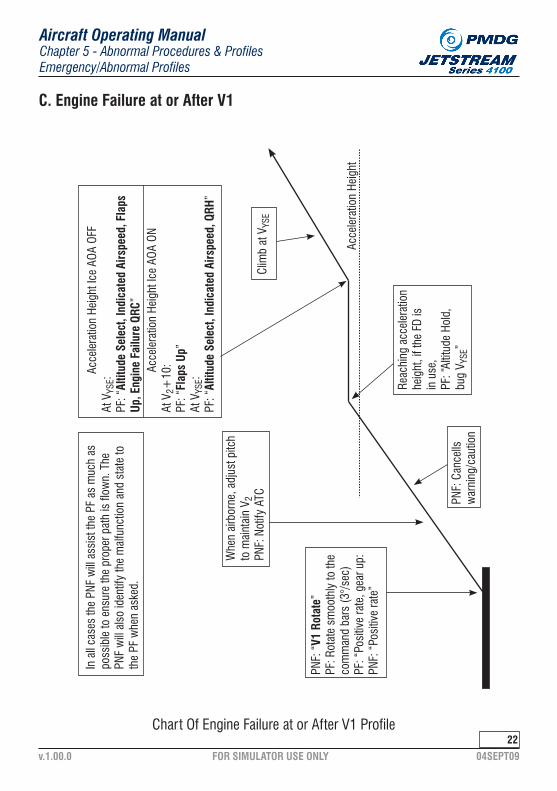
FOR SIMULATOR USE ONLY 04SEPT09v.1.00.0
Chapter 5 - Abnormal Procedures & ProfilesEmergency/Abnormal Profiles
Aircraft Operating Manual
22
C. Engine Failure at or After V1
Chart Of Engine Failure at or After V1 Profile
In a
ll ca
ses
the
PNF
will
assi
st th
e PF
as
muc
h as
po
ssib
le to
ens
ure
the
prop
er p
ath
is fl
own.
The
PN
F w
ill al
so id
entif
y th
e m
alfu
nctio
n an
d st
ate
to
the
PF w
hen
aske
d.
Whe
n ai
rbor
ne, a
djus
t pitc
h to
mai
ntai
n V 2
PNF:
Not
ify A
TC
Acce
lera
tion
Heig
ht Ic
e AO
A OF
FAt
VYS
E:
PF: “
Altit
ude
Sele
ct, I
ndic
ated
Airs
peed
, Fla
ps
Up, E
ngin
e Fa
ilure
QRC
”Ac
cele
ratio
n He
ight
Ice
AOA
ONAt
V2+
10:
PF: “
Flap
s Up
”At
VYS
E:PF
: “Al
titud
e Se
lect
, Ind
icat
ed A
irspe
ed, Q
RH”
Acce
lera
tion
Heig
ht
Clim
b at
VYS
E
Reac
hing
acc
eler
atio
n he
ight
, if t
he F
D is
in
use
,PF
: “Al
titud
e Ho
ld,
bug
V YSE
”PN
F: C
ance
lls
war
ning
/cau
tion
PNF:
“V1
Rot
ate”
PF: R
otat
e sm
ooth
ly to
the
com
man
d ba
rs (3
°/se
c)PF
: “Po
sitiv
e ra
te, g
ear u
p:PN
F: “
Posi
tive
rate
”

FOR SIMULATOR USE ONLY 04SEPT09v.1.00.0
Chapter 5 - Abnormal Procedures & ProfilesEmergency/Abnormal Profiles
Aircraft Operating Manual
2�
C. Engine Failure at or After V1
a. Engine Failure at or After V1 Profile Expanded
a) Crew Coordination
(1) If a special departure procedure is specified for the departure runway, the PNF will aid the PF as much as possible to ensure the proper track is flown.
(2) When the PF is certain the proper departure course is being flown, the PF will ask the PNF to identify and state the malfunction.
(3) While performing the QRH/QRC procedures, it is appropriate for the PF to assume ATC communication duties.
b) Takeoff Roll
(1) Normal profile until V1.
c) Rotation
(1) 5 kts. prior to V1 the PNF states, “V1’. The PF will move his hand from the Power Levers to the yoke.
(2) At VR, the PNF will state, Rotate”, the PF will rotate the aircraft slowly and smoothly to the command bars (7-10 degrees nose up).
(3) A bank angle of up to 5 degrees into the operating engine can help maintain directional control and climb performance.
d) Initial Climb
(1) At the first sign of positive rate, the PF will state, “Positive Rate, Gear Up”. The PNF will then state, “Positive Rate” and select the gear up.
i. Positive rate is defined as vertical speed, indicating a value greater than 0 FPM.
(2) If the PF delays his call, the PNF will state, “Positive Rate” first.
(3) If APR is not automatically activated, the PNF will press the APR O/RIDE button.

FOR SIMULATOR USE ONLY 04SEPT09v.1.00.0
Chapter 5 - Abnormal Procedures & ProfilesEmergency/Abnormal Profiles
Aircraft Operating Manual
24
e) V2 Climb
(1) Climb to acceleration height at V2.
i. If the FD is in use, press the TCS button when the correct pitch for V2 is achieved to adjust the command bars to hold V2.
ii. Alternatively, if the FD is in use, the PF may call, “Indicated airspeed”, and then press the TCS button when V2 is obtained to capture V2 as an lAS mode on the FD.
(2) When other duties allow, the PNF will call ATC to declare the emer-gency, briefly state initial intentions and ask them to stand by.
f) Acceleration Height
(1) The acceleration height is 400’ HAA.
(2) At acceleration height, lower the nose to approximately 5° and main-tain a zero rate of climb. Allow the Aircraft to accelerate to VYSE.
i. PF will call, “Altitude Hold, Bug VYSE”.
ii. At VYSE, PF calls for a horizontal and vertical mode on the flight director and for flap retraction (e.g., “Altitude Select, Indicated Airspeed, Flaps Up.”).
iii. With ice AOA ON at V2 + 10, PF states “Flaps Up”. The PF ac-celerates to VYSE, then calls for a horizontal and vertical mode on the flight director such as, “Altitude Select, Indicated Airspeed.”
g) VYSE Climb
(1) At VYSE and after the flaps have been retracted, the PF will pitch the aircraft to approximately 7° to 10° nose up and climb at VYSE and call for the QRC procedure by stating, “ QRC”.
(2) Once the engine is shut down and the controls are trimmed, the AP may be engaged.
(3) Until the crew is able to assure obstruction clearance by some other means, the crew must continue to comply with the engine failure departure procedure.

FOR SIMULATOR USE ONLY 04SEPT09v.1.00.0
Chapter 5 - Abnormal Procedures & ProfilesEmergency/Abnormal Profiles
Aircraft Operating Manual
2�
D. Engine Fire At Or After V1
1. An engine on fire may still be producing power. Consider current status of the aircraft, including the status of the other engine before shutdown.
2. Fly a normal vertical takeoff profile until flaps are up, and then perform the engine fire QRC.
E. Engine Failure In Cruise
a. General
1) In the event of an engine failure during high altitude cruise, the aircraft may not be able to maintain altitude, and a descent to a lower altitude must be expected.
2) If it is necessary to preserve altitude after the failed engine has been secured, set 100% RPM, Max Torque/ Red Line VRL (whichever occurs first) flows to 2 1/2 and fly at the Single Engine Enroute Climb Speed (See Chapter X PERFORMANCE for the Single Engine Enroute Climb Speed).
3) If altitude can not be maintained, descend at the Single-Engine Enroute Climb Speed until the descent is arrested.
· INTENTIONALLY LEFT BLANK ·

FOR SIMULATOR USE ONLY 04SEPT09v.1.00.0
Chapter 5 - Abnormal Procedures & ProfilesEmergency/Abnormal Profiles
Aircraft Operating Manual
2�
F. Single Engine Precision Approach
Chart Of Single Engine Precision Approach Profile
Clea
red
for a
ppro
ach:
PF: (
A/P
On):
Sele
cts
APR
on th
e Fl
ight
Dire
ctor
.PN
F: T
urns
taxi
ligh
t ON,
on
PA:”
Flig
ht A
ttend
ant,
be s
eate
d”.
Star
t con
figur
ing
appr
oxim
atel
y 3
to 5
NM
fro
m th
e FA
FPF
: ”Fl
aps
9”2
to 4
mile
s fro
m th
e FA
F:PF
: “Ge
ar D
own”
1 to
3 m
iles
from
the
FAF:
PF: “
Flap
s 1�
”
At th
e FA
F:PN
F: “
Fina
l Ap
proa
ch F
ix”
Appr
ox. a
t the
FAF
(G
S in
terc
ept)
PF: “
Flap
s 2�
, La
ndin
g Ch
eck”
PNF:
“10
00”
PF: “
Set m
isse
d ap
proa
ch
altit
ude”
PNF:
“__
___F
eet S
et”
PNF:
“20
0”PN
F: “
100”
PNF:
“Li
ghts
”PF
: “Co
ntin
uing
”PN
F: “
Runw
ay”
PF: “
Land
ing”
FAF
FOR SIMULATOR USE ONLY 04SEPT09v.1.00.0
Chapter 5 - Abnormal Procedures & ProfilesEmergency/Abnormal Profiles
Aircraft Operating Manual
F. Single Engine Precision Approach
2�
a. Navaid and FD Setup
a) General
(1) The J-41 may use FMS for missed approaches and holding.
(2) Ensure the approach frequencies are transferred from standby to in use.
b) FMS Intercept to a VHF Course
(1) LNAV should be selected in the EFIS display controller, and NAV should be armed on the Flight Director Mode Selector.
(2) Tune the approach frequency and push the V/L button to display the magenta-colored course needle and select the proper inbound course for the approach.
(3) Enter the assigned intercept heading or navigation fix in the FMS.
(4) Push the NAV button on the Flight Director Mode Selector so ARM and CAP both illuminate on the NAV selector.
(5) When the VHF course captures, LNAV will disarm and the VHF course will be displayed with a green needle.
(6) Fly the remainder of the approach as described by the specific profile.
b. Single-Engine Precision Approach Profile Expanded
1) The Single-Engine Precision Approach Profile has the same calls and final configuration as a Normal Precision Approach Profile. The only dif-ference is points at which the aircraft is configured for landing.
2) The entire profile is reprinted here for pilot convenience.
3) Timing the selection of the landing gear and each flap setting in coordina-tion with beginning the descent down the glide slope is critical to prevent the aircraft from getting behind the power curve.
· INTENTIONALLY LEFT BLANK ·

FOR SIMULATOR USE ONLY 04SEPT09v.1.00.0
Chapter 5 - Abnormal Procedures & ProfilesEmergency/Abnormal Profiles
Aircraft Operating Manual
2�
4) For engine failures on approach to landing that occur above 200’ AGL, the flight crew must consider factors such as weather, terrain, perfor-mance and emergency procedures to determine the safest course of action. Emergency checklists should be completed prior to landing.
a) Vectored for Approach
(1) Prior to intercepting the final approach course, LNAV should be disengaged by selecting V/L until LOC 1 and LOC 2 are shown in green on the EHSIs.
b) Cleared for Approach
(1) When cleared for the approach, the PF selects APR on the FD. The PNF turns the taxi light ON and announces on the PA, “Flight Attendant be Seated”.
(2) After LOC captured, set the heading bug to runway heading (+1- wind correction is allowed).
c) Configuring for Approach
(1) The initial approach should be flown at 170 KIAS.
(2) The aircraft should be configured for landing and on target speed by 1000’ above DA.
d) Inbound and within 3 to 5 miles of the FAF (GS alive).
(1) PF will call for “Flaps Nine”.
e) 2 -4 miles from the FAF (2 dots below GS)
(1) The PF will call for “Gear Down”.
(2) When the gear is down and locked, call, “Flaps 15°”.
· INTENTIONALLY LEFT BLANK ·

FOR SIMULATOR USE ONLY 04SEPT09v.1.00.0
Chapter 5 - Abnormal Procedures & ProfilesEmergency/Abnormal Profiles
Aircraft Operating Manual
29
f) At FAF (GS intercept)
(1) The PF will call for “Flaps Twenty-Five, Landing Checks”.
(2) The PNF will state, “Final Approach Fix”.
(3) The final approach should by flown at Target Speed to DH.
g) Altitude Call Outs
(1) At 1000’ above DH, the PNF will state, “One Thousand”. The PF will state, “Set Missed Approach Altitude”.
(2) The PNF sets the missed approach altitude with the altitude selec-tor and calls, “______ Feet Set”.
(3) At 200’ above DH, the PNF will state, “Two Hundred”.
(4) At 100’ above DH, the PNF will state, “One Hundred”.
h) Lights/Runway In Sight
(1) At any point on the approach, if the PNF sees the approach lights and not the runway, the PNF will state, “Lights”. The PF will state, “Continuing”. The flight may continue the approach to 100’ above TDZE with only the approach lights in sight.
· INTENTIONALLY LEFT BLANK ·

FOR SIMULATOR USE ONLY 04SEPT09v.1.00.0
Chapter 5 - Abnormal Procedures & ProfilesEmergency/Abnormal Profiles
Aircraft Operating Manual
�0
G. Single Engine Non-Precision Approach
Chart Of Single Engine Non-Precision Approach Profile
Clea
red
for a
ppro
ach:
PF: (
AP/O
N): S
elec
ts N
AVPN
F: S
elec
ts T
axi L
ight
ON
and
on P
A:“F
light
Atte
ndan
t be
Seat
ed”.
FAF
MDA
Star
t con
figur
ing
abou
t 3-
5NM
from
the
FAF.
PF: “
Flap
s 9”
At th
e FA
F:PN
F: “
Fina
l App
roac
h Fi
x”PF
: “No
te T
ime”
PF s
tart
s do
wn
usin
g VS
, 100
0 fp
mor
less
.
Step
-dow
n al
titud
e ca
ptur
ed:
PF: “
Set N
ext A
ltitu
de”
PNF:
“__
____
_ Fe
et S
et”.
PF: “
1000
”PF
: “20
0”PF
: “10
0”(a
ltitu
des
abov
e M
DA)
PNF:
“Li
ghts
”PF
: “Co
ntin
uing
”W
hen
leav
ing
MDA
PF: “
Leav
ing
MDA
, Gea
rDo
wn,
Fla
ps 1
�/2�
,La
ndin
g Ch
eck.
”PN
F: “
Runw
ay”
PF: “
Land
ing”
MDA
alti
tude
cap
ture
d:PN
F: “
MDA
___
___(
time/
dist
ance
) to
go”
PF: “
Set M
isse
d Ap
proa
ch A
ltitu
de”
PNF:
“__
____
_ Fe
et S
et”.

FOR SIMULATOR USE ONLY 04SEPT09v.1.00.0
Chapter 5 - Abnormal Procedures & ProfilesEmergency/Abnormal Profiles
Aircraft Operating Manual
�1
a. Navaid and FD Setup
a) General
(1) The J-41 is not approved to use FMS as the NAV source on final ap-proach (from FAF to MAP inclusive). Therefore, on final it is required to have the approach’s ground-based navaids selected, and this is considered to be how you are navigating.
G. Single Engine Non-Precision Approach
i. The J-41 may use FMS for missed approaches and holding.
b) FMS Intercept to a VHF Course
(1) LNAV should be selected in the EFlS display controller and NAV should be armed on the Flight Director Mode Selector.
(2) Tune the approach frequency and push the V/L button once to display the magenta-colored course needle and select the proper inbound course for the approach.
(3) Enter the assigned intercept heading or navigation fix in the FMS.
(4) Push the NAV button on the Elight Director Mode Selector, so ARM and CAP both illuminate on the NAV selector.
(5) When the VHF course captures, LNAV will disarm and the VHF course will be displayed with a green needle.
(6) Fly the remainder of the approach as described by the specific profile.
c) LOC only approaches
(1) The flight director should be set to NAV mode to track the localizer. Do not arm APR mode on the FD to fly LOC-only approaches.
d) VOR approaches
(1) The flight director should be set to APR mode to track a VOR ap-proach. The flight director will now apply the gains appropriate for a VOR approach.

FOR SIMULATOR USE ONLY 04SEPT09v.1.00.0
Chapter 5 - Abnormal Procedures & ProfilesEmergency/Abnormal Profiles
Aircraft Operating Manual
�2
d) NDB approaches
(1) ADF #1 and #2 should each be tuned to the navigation aid frequency to track the approach.
b. Single-Engine Non-Precision Approach Profile Expanded
a) Vectored for Approach
(1) Once in heading mode, each pilot will tune the approach frequency, set the final approach course and set the bearing pointers as required. The PNF may be asked to identify the navaids.
b) Cleared for the Approach
(1) The PNF will turn the Taxi Light ON when cleared for the approach.
(2) When approach clearance is received and the aircraft is on a heading to intercept the approach course (current heading within 90 degrees of approach course), ensure the FD NAV is armed to capture the course.
(3) The aircraft should be on published approach altitude at target speed with the next altitude displayed in the altitude preset prior to crossing the FAF.
c) Configuring for the Approach
(1) The initial approach should be flown at 170 KIAS.
(2) If runway conditions permit, it is recommended that the landing be made with Flaps 15.
d) Approximately 3 to 5 miles from the FAF
(1) PF will state, ‘Flaps 9”.
e) Approaching FAF
(1) The aircraft should be configured, on Target Speed, with the next altitude displayed in the altitude preset window and stabilized on the approach prior to crossing the FAF.

FOR SIMULATOR USE ONLY 04SEPT09v.1.00.0
Chapter 5 - Abnormal Procedures & ProfilesEmergency/Abnormal Profiles
Aircraft Operating Manual
��
f) Final Approach Fix
(1) The PNF will state, “Final Approach Fix”. The PF will state, “Note Time.”
g) Descent
(1) Upon crossing any fix where a descent IS to be initiated, the PF will select ALTSEL, VS and set a vertical speed of 1000 fpm down. Higher descent rates my be used for any portion of the descent that is above 1000’ above MDA.
(2) As the FD displays ALT, the PF will call, “Set Next Altitude.” The PNF sets the next step-down altitude with the altitude selector and calls, “____ Feet Set”.
i. Alternatively, the PF may call for ALT to be manually selected to expedite the process. The call will be, “Altitude Hold, Set Next Altitude”.
(3) At 1000 above MDA, the PNF will state, “One Thousand”.
(4) At 200 above MDA, the PNF will state, “Two Hundred”.
(5) At 100’ above MDA, the PNF will state, “One Hundred”.
i. These calls will be omitted when descending to step-down alti-tudes other than MDA.
(6) At MDA, the PNF will call, “MDA, (time/distance) To Go”.
(7) As the FD displays ALT after reaching MDA, the PF will call, “Set Missed Approach Altitude”.
(8) The PNF sets the missed approach altitude with the altitude selector and calls, “____ Feet Set”.
(9) Descents should be done at no more than 1000 FPM.
· INTENTIONALLY LEFT BLANK ·

FOR SIMULATOR USE ONLY 04SEPT09v.1.00.0
Chapter 5 - Abnormal Procedures & ProfilesEmergency/Abnormal Profiles
Aircraft Operating Manual
�4
h) Lights/Runway In Sight
(1) At any point on the approach, if the PNF sees the approach lights and not the runway, the PNF will state, “Lights”. The PF will state, “Con-tinuing”. If in a position to make a normal descent to the runway, the flight may descend to 100’ above the TDZE with only the approach lights in sight.
(2) When the PNF sees the runway, the PNF will state, “Runway”. The PF will look outside, see the runway, and state, “Landing”.
CAUTION: Due to probable cancellation of the gear warning horn, the crew must remember to lower the gear when leaving MDA.
(3) When in a position to make a normal descent to landing, the PF will state, “Leaving MDA, Gear Down, Flaps Fifteen” or “Flaps Twenty Five”, Landing Checks”.
1. If an engine failure occurs and all of the following conditions are met, the ap-proach may continue:
1) Weather at least 1000-3.
2) Within 5NM of the runway.
3) Descending and on final approach.
4) If continwng the approach, advance the power on the operating engine and maintain a stabilized approach.
H. Engine Failure On Approach
2. If at any time the approach becomes unstabilized, execute a missed approach.
· INTENTIONALLY LEFT BLANK ·

FOR SIMULATOR USE ONLY 04SEPT09v.1.00.0
Chapter 5 - Abnormal Procedures & ProfilesEmergency/Abnormal Profiles
Aircraft Operating Manual
��
I. Single-engine Missed Approach Profile
Chart Of Single Engine Missed Approach Profile
In a
ll ca
ses,
the
PNF
will
assi
st th
e PF
as
muc
h as
pos
sibl
e to
ens
ure
the
prop
er p
ath
is fl
own.
The
PNF
will
also
iden
tify
the
mal
func
tion
and
stat
e it
to th
e PF
whe
n as
ked.
PNF:
Sta
te th
e in
itial
act
ions
of t
he
mis
sed
appr
oach
.PF
: “He
adin
g, A
SL, I
AS”
PNF
or P
F: “
Mis
sed
Appr
oach
”PF
: Pre
ss th
e GA
but
ton,
sel
ect m
ax
pow
er, a
nd p
itch
to th
e co
mm
and
bars
.PF
: “Se
t Pow
er, F
laps
9”
PF: “
Posi
tive
Rate
, Gea
r Up”
PNF:
“Po
sitiv
e Ra
te”
Acce
lera
tion
heig
ht:
PF: “
Altit
ude
Hold
, Bu
g V Y
SE“
Acce
lera
te in
leve
l fli
ght.
PF: C
limbs
at V
YSE
to a
saf
e al
titud
e.
Ice
AOA
OFF
At a
ccel
ratio
n he
ight
and
at V
YSE:
PF
: “Al
titud
e Se
lect
, Ind
icat
ed A
irspe
ed, F
laps
Up
, QRH
”
Ice
AOA
ONAt
V2+
10:
PF: “
Flap
s Up
”At
VYS
E:PF
: “Al
titud
e Se
lect
, Ind
icat
ed A
irspe
ed, Q
RH”
Acce
lera
tion
Heig
ht

FOR SIMULATOR USE ONLY 04SEPT09v.1.00.0
Chapter 5 - Abnormal Procedures & ProfilesEmergency/Abnormal Profiles
Aircraft Operating Manual
I. Single-engine Missed Approach Profile
��
a. Single-Engine Missed Approach Profile Expanded
a) Crew Coordination
(1) In the event the engine failed during the missed approach, and when the PF is certain the proper missed approach course is being flown, workload permitting, the PF will ask the PNF to identify and state the exact malfunctions.
WARNING: This procedure should not be started at a height lower than 200 ft. AGL. If the decision to discontinue the approach has not been made by the time ______ft this height has been reached, the aircraft is normally committed to land.
b) Initial Climb
(1) At the “Missed Approach” call, the PF will simultaneously advance the power to max torque/EGT, press the go-around button, pitch to the command bars and call, “Set Power, Flaps Nine”.
(2) The PNF will ensure 100% torque or VRL, whichever occurs first, is set and then retract the flaps to 9.
(3) Immediately after flap selection, PF calls, “Positive Rate, Gear Up”. Do not wait for an actual positive rate.
(4) The PNF will state, “Positive Rate” and retract the gear. If the PF de-lays his call, the PNF will state, “Positive Rate” first.
(5) Climb at V2 until reaching acceleration height.
(6) A 5° bank into the operating engine can help maintain directional control and climb performance.
c) Call ATC
(1) When workload permits, the PNF will report the Missed Approach to ATC and state intentions.
(2) Until the aircraft is above 600’ AGL, properly configured and under positive control, the PNF’s sole duties will be to assist the PF in con-figuring the aircraft and obtaining ATC instructions.

FOR SIMULATOR USE ONLY 04SEPT09v.1.00.0
Chapter 5 - Abnormal Procedures & ProfilesEmergency/Abnormal Profiles
Aircraft Operating Manual
��
d) Navigation
(1) The PNF will state the first actions of the missed approach procedure (e.g., “Climb straight ahead to 2000’, then turn left to 210).
(2) The PF will call for a horizontal and vertical mode on the flight direc-tor, such as “Heading, Altitude Select, Indicated Airspeed”, and fly the missed approach procedure until the FMS or other NAVAID is ready.
(3) At 500’ AGL, the AP may be turned ON.
(4) The PNF will then begin to prepare the FMS, and other NAVAIDS as necessary to fly the missed approach.
e) Acceleration Height
(1) The acceleration height is 400’ HAA.
(2) At acceleration height, lower the nose to approximately 5 degrees and maintain a zero rate of climb. Allow the Aircraft to accelerate to VYSE.
i. PF will call, “Altitude Hold, Bug VYSE”.
ii. At VYSE, the PF calls for a horizontal and vertical mode on the flight director, and for flap retraction (e g., “Altitude Select, Indi-cated Airspeed, Flaps Up”). The PF will climb at VYSE until a safe altitude is reached.
iii. With ice AOA ON at V2 + 10, PF states, “Flaps Up”. The PF ac-celerates to VYSE, then calls for a horizontal and vertical mode on the flight director, such as, “Altitude Select, Indicated Airspeed.” The PF will climb at “Ice AOA ON” VYSE until a safe altitude is reached.
(3) After a climb at VYSE is established, the PF will call “QRH” and the PNF will perform the “Single-Engine Configuration” check in the QRH. If the engine failure occurred during the missed approach, call ”QRC”.
· INTENTIONALLY LEFT BLANK ·

FOR SIMULATOR USE ONLY 04SEPT09v.1.00.0
Chapter 5 - Abnormal Procedures & ProfilesEmergency/Abnormal Profiles
Aircraft Operating Manual
��
J. Emergency Descent
1. The Emergency Descent should be initiated in the event of smoke, fumes, explosive decompression or an uncontrollable increase in cabin altitude.
1) If the loss of cabin pressure is slow, use the CABIN HI ALT QRC/QRH to attempt to control the cabin pressurization prior to initiating an emer-gency descent.
2. Emergency descents must be accomplished in a prompt and timely manner, but the policy of “Do Not Rush” still applies.
3. Especially from high altitudes, the initiation of an emergency descent must be a deliberate and controlled maneuver to avoid overspeeding the airplane.
OXYGEN MASKS ......... (AS REQUIRED) DON 100%COMMUNICATION ....... ESTABLISHSEATBELT SIGN .......... CYCLE 3X / ONTRANSPONDER .......... 7700ATC ............................ NOTIFYPOWER LEVERS ......... FLIGHT IDLE 15%CONDITION LEVERS ... FLIGHT IF EXECUTING A HIGH SPEED DESCENTDESCENT AIRSPEED .. VMOP/A ............................. PASSENGERS BRIEF
IF EXECUTING A LOW SPEED DESCENT:
a) Emergency Descent QRC
FLAPS ......................... 9°LANDING GEAR ........... DOWNFLAPS ......................... 15°DESCENT AIRSPEED ... 160 KIASP/A .............................. PASSENGERS BRIEF

FOR SIMULATOR USE ONLY 04SEPT09v.1.00.0
Chapter 5 - Abnormal Procedures & ProfilesEmergency/Abnormal Profiles
Aircraft Operating Manual
�9
WARNING: Donning Oxygen Masks and Establishing Communications is listed on the QRC, but due to the short time of useful consciousness at high altitudes and/or the possibility of being overcome by fumes, these actions must be done quickly by memory and simultaneously by both pilots.
a) OXYGEN MASKS(as required) .......... - DON/100%
b) COMMUNICATIONS .......................... - ESTABLISH
c) SEATBELT SIGN ............................... - FLASH-ON
d) TRANSPONDER ............................... - 7700
e) ATC ................................................. - NOTIFY
(1) If required due to decompression or smoke/fumes, both pilots will simultaneously don their 02 masks.
(1) After donning the 02 mask, put your headset on over the mask harness and select MASK on the Audio Control Panel micro-phone selection switch.
(1) The PNF will cycle the Fasten Seatbelt sign three times to the ON position.
(1) The PNF sets 7700 in the transponder.
(1) The PNF will notify ATC of the need to accomplish an Emergency Descent and request vectors to do so. For example: “Mayday, Mayday, *CALLSIGN HERE* REQUIRES immediate vectors for an Emergency Descent”.
(2) Unless there is a delay in communication with ATC, the actual de-scent should not be started without indication from ATC it is safe to do so. In the crowded airspace we generally operate in, there is a real possibility of descending into another aircraft.
b) Emergency Descent Check Expanded

FOR SIMULATOR USE ONLY 04SEPT09v.1.00.0
Chapter 5 - Abnormal Procedures & ProfilesEmergency/Abnormal Profiles
Aircraft Operating Manual
40
i. If structural damage is suspected, accomplish a Low Speed Descent.
ii. If structural damage is not suspected, accomplish a High Speed Descent.
f) HIGH / LOW SPEED DESCENT .......... - INITIATE
(1) The Captain will determine if a High or Low Speed descent will be initiated.
(2) Descend to 10,000’ or minimum safe altitude, whichever is higher.
g) POWER LEVERS .............................. - FLIGHT IDLE
(1) PF moves power levers to flight idle.
(2) If available, use the autopilot to fly the descent. The PF will select lAS mode and then reduce power to idle. Then reset the speed bug to the desired airspeed.
(3) If the autopilot is not available, the PF will lower the pitch smoothly as he reduces power to idle.
h) CONDITION LEVERS ........................ - FLIGHT
(1) PNF will move the condition levers to flight.
i) High / Low Speed ............................ - FLIGHT
(1) Accomplish procedures as described on the QRC.
j) P/A .................................................. - BRIEF PASSENGERS
(1) The PNF will make an announcement over the P/A. For example: “Ladies and Gentlemen, please remain seated, fasten your seat-belt and ensure your oxygen mask is on. We will be leveling off at a safe altitude in a few minutes”.

FOR SIMULATOR USE ONLY 04SEPT09v.1.00.0
Chapter 5 - Abnormal Procedures & ProfilesEmergency/Abnormal Profiles
Aircraft Operating Manual
41
K. Zero Or Partial Flap Landing
1. Assign PF/PNF duties.2. Select GPWS flaps override.3. Follow the appropriate profile for the approach flown, except eliminate all calls
for flap settings.4. Fly a normal 3° glide slope, which will require a higher nose attitude than
normal.5. Three to five miles from the FAF and at or below 170 kts call, “Gear Down,
Landing Check”.6. Do not prolong the flare.7. Use maximum braking and reverse thrust as required.
L. Ditching
1. Complete the QRC and consult QRH as time permits2. Check that crew and passenger life vests, seat belts, and harnesses secure.3. Configure the aircraft for a gear up, flaps 25 touchdown.4. Touchdown should be at a minimum rate of descent, in a flat attitude, at VREF
flap 25 speed.5. The Captain will direct cabin crew and passengers to start evacuating using
the overwing exits.
CAUTION: The main door and rear emergency exit should not be used.
6. Passengers and crew should not inflate their life vests until they are outside the aircraft.
· INTENTIONALLY LEFT BLANK ·

FOR SIMULATOR USE ONLY 04SEPT09v.1.00.0
Chapter 5 - Abnormal Procedures & ProfilesEmergency/Abnormal Profiles
Aircraft Operating Manual
42
M. Reserved
· INTENTIONALLY LEFT BLANK ·

FOR SIMULATOR USE ONLY 04SEPT09v.1.00.0
Chapter 5 - Abnormal Procedures & ProfilesEmergency/Abnormal Profiles
Aircraft Operating Manual
4�
a. Windshear During Takeoff Roll Prior To V1.
1) The primary indication of windshear during takeoff roll is stagnation or abnormal acceleration of lAS.
2) The pilot noticing the windshear will call, “Abort, Abort”.
3) The PF will abort the takeoff.
N. Windshear Recovery
b. Windshear After V1
1) The primary indications of windshear after liftoff include:
(1) Uncommanded gain or loss of lAS.
(2) Uncommanded gain or loss of vertical speed.
2) Pilot noticing windshear calls, “Windshear”.
3) The PF will call “Max Power” and will advance the power levers full forward.
4) PNF sets/ensures maximum (firewall) power.
5) PF will initially rotate to 15° nose up or until intermittent stickshaker, whichever occurs first.
6) Make smooth, steady adjustments to pitch attitude to maintain airspeed Just above the shaker (EFlS lAS turns red).
7) Intermittent activation of the stickshaker may be necessary to maintain a positive rate of climb. Always respect the stickshaker.
8) Maintain current aircraft configuration.
9) Maintain wings level.
10) The PNF will monitor flight instruments and frequently call out airspeed, airspeed trend, vertical speed and altitude (e.g., “Altitude 200’, climbing”)
11) The recovery procedure will continue until clear of windshear and clear of all obstacles.

FOR SIMULATOR USE ONLY 04SEPT09v.1.00.0
Chapter 5 - Abnormal Procedures & ProfilesEmergency/Abnormal Profiles
Aircraft Operating Manual
44
12) When the windshear recovery is complete, accomplish normal takeoff calls and procedures to configure the aircraft.
c. Windshear on Approach
1) The primary indications of windshear on approach are:
(1) Uncommanded gain or loss of lAS.
(2) Uncommanded gain or loss of vertical speed.
2) If a windshear is noted during an approach, the pilot noticing will call, “Windshear”.
3) The PF will simultaneously call, ‘Max Power” and advance the power levers full forward.
4) PNF will ensure maximum (firewall) power.
5) PF will initially pitch to 15° nose up or until intermittent stickshaker, whichever occurs first.
6) Make smooth, steady adjustments to pitch attitude to maintain airspeed just above the shaker (EFIS lAS turns red).
7) Intermittent activation of the shaker may be necessary to maintain a posi-tive rate of climb. Always respect the stickshaker.
8) Maintain the current aircraft configuration.
9) Maintain wings level.
10) The PNF will monitor flight instruments and frequently call out airspeed, airspeed trend, vertical speed and altitude.
11) The recovery procedure will continue until clear of windshear and clear of all obstacles.
12) When the windshear recovery is complete, accomplish normal go-around calls and procedures to configure the aircraft.
· INTENTIONALLY LEFT BLANK ·

FOR SIMULATOR USE ONLY 04SEPT09v.1.00.0
Chapter 5 - Abnormal Procedures & ProfilesEmergency/Abnormal Profiles
Aircraft Operating Manual
4�
0. GPWS Alerts
1. GPWS alerts require an immediate and positive response by the crew with an acknowledgement (e.g., “Correcting”, “Missed Approach” or “Windshear”), and when required, an immediate correction by the PF.
2. In clear visual meteorological conditions when the flight crew can immediately confirm a false GPWS warning, the warning may be disregarded.
3. ATC should be notified as soon as possible after a GPWS alert that results in a deviation from the clearance.
4. GPWS alerts and responses:Simultaneously call ‘Max Power”, disconnect the A/P, advance the power levers fully forward and pitch 15° nose up or until stickshaker, whichever oc-curs first.
ALERT RESPONSE
“Pull up, Pull Up” or “Terrain, Terrain”
Continue the recovery procedure until all alerts cease and it is confirmed that ground clearance exists. Respect the stickshaker.
“Sink Rate” Decrease the rate of descent until the warning ceases.
“Don’t Sink” Immediately establish level flight or a positive rate of climb.
“Too Low Terrain” Confirm a positive rate of climb, cross-check terrain clearance visually and with ATC, climb as necessary to avoid terrain.
“Too Low Gear” Execute a missed approach if gear position cannot be immediately verified.
“Too Low, Flaps” Activate the flap override if landing with flaps up. Execute a missed approach if flap position cannot be immediately verified.
“Glideslope” Return to glideslope or execute a missed approach.
“Bank Angle” Shallow out rate bank angle until warning ceases.

FOR SIMULATOR USE ONLY 04SEPT09v.1.00.0
Chapter 5 - Abnormal Procedures & ProfilesEmergency/Abnormal Profiles
Aircraft Operating Manual
4�
P. TCAS Alerts
1. The TCAS will give a (TA) warning audio and amber circle on the display when traffic is within 20 to 48 seconds of the closest point of approach.
AURAL ALERT RESPONSE
‘Traffic, Traffic” Attempt to visually see and avoid the traffic. If unable to establish visual contact, query ATC.
a. Traffic Advisory (TA)
WARNING: Do not carry out maneuvers based solely on traffic advisories (TA) without visual contact of the traffic.
· INTENTIONALLY LEFT BLANK ·

FOR SIMULATOR USE ONLY 04SEPT09v.1.00.0
Chapter 5 - Abnormal Procedures & ProfilesEmergency/Abnormal Profiles
Aircraft Operating Manual
4�
Q. Reserved
· INTENTIONALLY LEFT BLANK ·

FOR SIMULATOR USE ONLY 04SEPT09v.1.00.0
Chapter 5 - Abnormal Procedures & ProfilesEmergency/Abnormal Profiles
Aircraft Operating Manual
4�
a. Stall Recovery
1) The hierarchy of stall recovery:
R. Stalls
(1) Maintain aircraft control
(2) Minimization of altitude loss
(3) Recovery of airspeed
2) All stall recoveries use the same procedures and calls, regardless of cur-rent aircraft configuration. The PF will make all flap calls, even if the flaps are UP. If the flaps are in a position less than what was called, the PNF will disregard the flap call.
3) At the first indication of a stall, simultaneously apply maximum power, pitch to 8° up and call, “Max Power Flaps 9°”.
4) Adjust pitch to maintain at or just above stickshaker until the altitude begins to increase.
5) When a positive rate of climb is established, the PF will state, “Positive rate, Gear Up”. PNF will verify a positive rate of climb and call, “Positive Rate” and select gear UP.
(1) If the PF delays his positive rate call, the PNF will call, “Positive Rate” first.
6) At VYSE and above acceleration height, the PF will call, “Flaps Up”.
7) Resume normal flight.
b. Demonstrating Stall Recovery Procedures
1) The purpose of demonstrating stall recovery is to prove mastery of air-craft control through a full range of airspeed and configuration changes.
(1) When training and checking stalls, the demonstration is considered complete when the aircraft has returned to stable flight at the altitude and airspeed at which it began.

FOR SIMULATOR USE ONLY 04SEPT09v.1.00.0
Chapter 5 - Abnormal Procedures & ProfilesEmergency/Abnormal Profiles
Aircraft Operating Manual
49
2) Entries and recoveries will be performed as described below:
(1) PF begins the maneuver at 170 knots and calls “Maneuvering Check”. PNF performs the maneuvering check items.
i. Set 100% RPM.
ii. Brief the stall speed.
(2) Reduce power to 20% torque for the Landing Configuration Stall and 10% for all other stalls.
(3) Configure the airplane:
i. Cruise Configuration Stall — Gear and Flaps Up.
ii. Takeoff Configuration Stall — Flaps 9, enter a 15° bank at 120 knots.
iii. Landing Configuration Stall — Gear Down, Flaps 25.
(4) Once the aircraft slows to 120 kts, stop elevator trim inputs.
(5) At the first indication of a stall, simultaneously apply full power, pitch to 8°, level the wings and call, “Max Power Flaps 90°”.
(6) When a positive rate of climb is established the PF will state, “Posi-tive rate, Gear Up”.
(7) PNF “Positive Rate” - PNF will confirm a positive rate of climb, then retract the landing gear.
(8) At acceleration height and VYSE:
i. PF: “Flaps Up, Climb power” — PNF retracts flaps and ensures the power is set within EGT and Torque limits.
ii. Allow aircraft to accelerate to climb speed.
(9) At 140 kts. the PF calls, “Cruise Power”.
· INTENTIONALLY LEFT BLANK ·

FOR SIMULATOR USE ONLY 04SEPT09v.1.00.0
1
Table of Contents
Aircraft Operating Manual
Non-Routine Procedures
GENERAL 6-1-3
A. Introduction 6-1-3
COLD WEATHER OPERATIONS 6-2-4
A. General 6-2-4B. Preflight 6-2-4C. Deicing Procedures 6-2-5D. Ground Operations 6-2-5E. Takeoff 6-2-6F. Flight 6-2-7G. Inadvertent Flight In Severe Icing Conditions 6-2-9H. Landing 6-2-11 I. Post Flight 6-2-12
Table of Contents - Non-Routine Procedures
HOT WEATHER OPERATIONS 6-3-13
A. General 6-3-13B. Ramp Operations 6-3-13C. Taxi 6-3-13D. Takeoff 6-3-14E. Landing 6-3-14
FMS INOPERATIVE 6-4-15
A. General 6-4-15B. Navigation/Flight Planning Inop. 6-4-15C. Communication Inop. 6-4-16
· INTENTIONALLY LEFT BLANK ·

FOR SIMULATOR USE ONLY 04SEPT09v.1.00.0
2
Table of Contents
Aircraft Operating Manual
Non-Routine Procedures (continued...)
PRESSURIZATION 6-5-17
A. Unpressurized Flight 6-5-17B. Manual Pressurization 6-5-18C. Cabin Differential Pressure Table 6-5-18
Table of Contents - Non-Routine Procedures
FERRY WITH THE GEAR EXTENDED 6-6-20
A. Ferry Flights 6-6-20
START LOCKS 6-7-21
A. Start Locks Not Engaged 6-7-21
· INTENTIONALLY LEFT BLANK ·

FOR SIMULATOR USE ONLY 04SEPT09v.1.00.0
A. Introduction
General
1. This chapter contains procedures, guidance and data to aid flight crews dealing with:
Chapter 6 - Non-Routine ProceduresGeneral
Aircraft Operating Manual
�
1) Adverse weather
2) Unusual aircraft configurations
3) Inoperative equipment
· INTENTIONALLY LEFT BLANK ·

FOR SIMULATOR USE ONLY 04SEPT09v.1.00.0
A. General
Cold Weather Operations
1. This chapter contains procedures, guidance and data to aid flight crews dealing with:
Chapter 6 - Non-Routine ProceduresCold Weather Operations
Aircraft Operating Manual
4
1) The winter season presents additional problems to airplane opera-tions resulting from low temperatures, and the potentially hazardous effects of precipitation and contamination on the airplane and aircraft movement areas.
2) Cold weather operations refer to ground handling, takeoffs and landings conducted on surface conditions where frozen moisture is present. These conditions are commonly encountered when the sur-face temperature is at or below 0°C, although frozen moisture may be present and persist for a significant time at higher temperatures.
B. Preflight
1. In addition to the normal preflight actions, look for the following items:
1) Winterization kit removed.
2) Water drains in the pressurized fuselage are clear.
3) Static vents have no frost, snow, or ice.
4) Pitot heads have no frost, snow and ice.
5) Water drains in the tailcone are not blocked.
6) Ensure the engines are clear of ice and snow. Do not start an engine if there is ice on the propeller, air inlet, spinner, or damage could result.
7) For the landing gear and the landing gear bays, make sure:
(1) The uplock and downlock mechanisms and gear microswitch as-semblies are free of ice and snow.
(2) Wheel brakes are clean and are free of ice and snow.
(3) Landing gear legs and bay are clean and are free of ice and snow.

FOR SIMULATOR USE ONLY 04SEPT09v.1.00.0
Chapter 6 - Non-Routine ProceduresCold Weather Operations
Aircraft Operating Manual
�
8) Closely inspect the condition of the deice boots and propeller deice mats.
9) The ice observation lights should operate for night operations.
C. Deicing Procedures
1. See Ground Deicing and Anti-Icing Procedures for the most current general procedures.
a) Deicing preparation
1) Before fluid is applied:
a) FMS Close out page ........... Select Deice - YES
b) Engines ............................. Shutdown
c) Battery Voltage .................. Monitor
b) Post Deicing Procedures:
a) Turn Check ............................... Complete
(1) Resume normal operations beginning with the Turn Check.
(2) Delay turning the flows ON until clear of the glycol area to avoid ingesting glycol fumes into the cabin.
(3) Do not single-engine taxi in icing conditions.
D. Ground Operations
1. During ground operations in icing conditions, it is very important to use the ic-ing protection. If the OAT is 5°C or less, the igniters will be turned on, followed by the engine/elevator heat, then the propeller heat. Propeller and Engine/El-evator anti- icing must be switched OFF on the ground when the applicable engine is not running.
2. Extreme care should be taken during ground operations in the vicinity of heavy snow accumulations (snow berms, etc.), due to a propeller clearance of only 13 inches.

FOR SIMULATOR USE ONLY 04SEPT09v.1.00.0
Chapter 6 - Non-Routine ProceduresCold Weather Operations
Aircraft Operating Manual
�
a) Taxiing
1) Taxi speed should be minimized when standing water or slush is to be encountered. Liquid displaced by the nosewheel could be ingest-ed by an engine and cause a flameout.
2) If an engine flameout does occur, do not attempt a relight during the rundown. Use the following procedure for relight:
CONDITION LEVER (Affected Engine) FEATHER/SHUTOFF
When the engine has stopped
CONDITION LEVER TAXI
When the engine has stopped
PROPELLER RETURN TO START LOCKNORMAL START PROCEDURES ACCOMPLISH
E. Takeoff
1. Takeoffs in Icing conditions require that the engine/elevator heat and propeller heat be ON, flows OFF, APR armed and ignition CONTINUOUS.
2. For performance considerations, see Chapter 6. DO NOT take off with any deposits of snow, ice, or slush adhering to the airframe.
3. “Takeoff in Icing” speeds will be set for takeoff.4. If Type II and or Type IV fluids are used, the following is required:
1) Aircraft must use ICE ON speeds for V1, VR, V2 and VYSE, irrespective of ambient conditions.
2) This means that whenever the aircraft is de/anti-iced with Type II or IV fluids, you must use the icing ON speeds during takeoff even when the weather is clear and environmental conditions would not warrant the use of icing speeds.
5. After the application of Type II or IV fluid, control movement remains normal, but control forces required for rotation or takeoff may be higher than normal.

FOR SIMULATOR USE ONLY 04SEPT09v.1.00.0
Chapter 6 - Non-Routine ProceduresCold Weather Operations
Aircraft Operating Manual
�
F. Flight
1. See Chapter 3 for definition of icing conditions in the air.2. With the Engine/Elevator heat selected on, the lcing/AOA light will come
on once the aircraft accelerates through 145 kts, adjusting the Low Speed Awareness tape upwards. You will note a decrease in performance with the engine elevator heat selected ON.
3. During flight in icing conditions, monitor the aircraft for ice accumulation. The ICE DETECT light is a good indication that the aircraft is accumulating ice on some parts of the airframe.
4. Ice accumulates on the sharpest leading edges first Use the windshield wipers and the wings to get an idea of the rate of accumulation. Fly at altitudes that minimize icing conditions.
5. Periodically disconnect the autopilot, and gently exercise the flying controls in all 3 axes to ensure that no hinge freezing has occurred.
6. Because of the location of the horizontal stabilizer, it is possible for the tail to accrete ice at a higher rate than the wings.
1) When using ice protection, it is good a practice to turn it on in the following sequence:
a. Turning ice protection ON in flight
(1) Continuous Ignition - ON
(2) L Eng / EIev anti-ice and L PROP heat - ON
(3) R Eng / Elev anti-ice and R PROP heat - ON
· INTENTIONALLY LEFT BLANK ·

FOR SIMULATOR USE ONLY 04SEPT09v.1.00.0
Chapter 6 - Non-Routine ProceduresCold Weather Operations
Aircraft Operating Manual
�
b. Operating airframe deice
1) The greatest degradation in aerodynamic characteristics occurs during formation of the first 0.5 in. to 0.75 in. thickness of ice. When operating airframe deice, use this procedure:
(1) Use the .5 in. ice depth fence to judge the thickness of ice on the wings. Optimum thickness for ice shedding will vary according to the nature of the ice, but a depth of at least 0.25 in. to 0.5 in. should be allowed to accumulate on the wings before the boots are operated.
c. Turning OFF Engine/Elevator Anti-Ice and ICE AOA
1) Upon leaving icing conditions with no further icing expected and when the engines and propellers are clear of ice accretion:
(1) PROPELLER ICE PROTECTION switches select OFF.
(2) ENG/ELEV ICE PROTECTION switches select OFF.
(3) IGNITION switches select NORMAL.
2) When the airframe is observed to be clear of ice accretion on both protected and unprotected parts:
(1) Operate ICING AOA CANCEL switch.
(2) Confirm the [ICING AOA] caption goes off.
· INTENTIONALLY LEFT BLANK ·

FOR SIMULATOR USE ONLY 04SEPT09v.1.00.0
Chapter 6 - Non-Routine ProceduresCold Weather Operations
Aircraft Operating Manual
9
G. Inadvertent Flight In Severe Icing Conditions
1. It has been determined that it is possible for aircraft to encounter icing condi-tions that are greater than the aircraft was originally designed for. The purpose of the AD is to minimize the potential hazards associated with operating the airplane in severe icing conditions, by providing more clearly defined proce-dures and limitations associated with such conditions.
WARNING: Severe icing may result from environmental conditions outside those for which the airplane is certified. Flight in freezing rain, freezing drizzle, or mixed Icing conditions (super-cooled liquid water and ice crystals) may result in ice build-up on protected surfaces, exceeding the capabil-ity of the ice protection system, or may result in ice forming aft of the protected surfaces. This ice may not be shed using the ice protection systems, and may seriously degrade the performance and controllability of the airplane.
a. Detection
1) During flight, severe icing conditions that exceed those for which the airplane is certificated shall be determined by the following visual clues. If one or more of these visual clues exist, immediately request priority handling from Air Traffic Control to facilitate a route or an altitude change to exit the icing conditions.
(1) Unusually extensive ice accreted on the airframe in areas not normally observed to collect ice.
(2) Accumulation of ice on the upper surface of the wing, aft of the protected area.
(3) Accumulation of ice on the propeller spinner, farther aft than normally observed.
2) The following weather conditions may be conducive to severe in-flight icing:
(1) Visible rain at temperatures below 0° C ambient air temperature.
(2) Droplets that splash or splatter on impact at temperatures below 0°C ambient air temperature.

FOR SIMULATOR USE ONLY 04SEPT09v.1.00.0
Chapter 6 - Non-Routine ProceduresCold Weather Operations
Aircraft Operating Manual
10
b. Operation
1) Since the autopilot may mask tactile cues that indicate adverse changes in handling characteristics, use of the autopilot is prohibited when any of the visual cues specified above exist, or when unusual lateral trim requirements or autopilot trim warnings are encountered while the airplane is in icing conditions.
2) All icing detection lights must be operative prior to flight into icing conditions at night.
NOTE: This supersedes any relief provided by the Master Minimum Equip-ment List (MMEL).
c. Exiting
1) These procedures are applicable to all flight phases from takeoff to landing. Monitor the ambient air temperature. While severe icing may form at temperatures as cold as -18°C, increased vigilance is war-ranted around freezing with visible moisture present. If the visual cues specified previously, or as specified in the Limitations Section of the AFM for identity of severe icing conditions, are observed, accomplish the following:
(1) Immediately request priority handling from Air Traffic Control to facilitate a route or an altitude change to exit the severe icing conditions, in order to avoid extended exposure to flight condi-tions more severe than those for which the airplane has been certificated.
(2) Avoid abrupt and excessive maneuvering that may exacerbate control difficulties.
(3) Do not engage the autopilot.
(4) If the autopilot is engaged, hold the control wheel firmly and disengage the autopilot.
(5) If an unusual roll response or uncommanded roll control move-ment is observed, reduce the angle-of-attack.

FOR SIMULATOR USE ONLY 04SEPT09v.1.00.0
Chapter 6 - Non-Routine ProceduresCold Weather Operations
Aircraft Operating Manual
11
(6) Do not extend flaps during extended operation in icing conditions. Operations with flaps extended can result in a reduced wing angle of attack, with the possibility of ice forming on the upper surface further aft on the wing than normal, possibly aft of the protected area
(7) If the flaps are extended, do not retract them until the airframe is clear of ice.
(8) Report these weather conditions to Air Traffic Control and Dis-patch.
H. Landing
1. Landing in icing conditions requires the use of “lcing/AOA On” speeds.
(1) Magenta - “Ice AOA ON”, Target “lce/AOA on” VYSE
(2) White - “Ice AOA ON”, V2 “Ice/AOA on” V2
(3) Blue - “Ice AOA ON”, VREF “Ice/AOA on” VREF flaps 15° or 25°
(4) Green - “Ice AOA ON”, VYSE
a. Flaps
(1) Normal landings with all deicing systems operational are flaps 25°. If ice is still adhering to the wings, 15° flaps is recommend-ed. If airframe deicing is inoperative, 15° flaps is the maximum authorized flap setting.
(2) High landing weights can result in the flap 25 target speed being very close to the 140 knot, flap 25 limitation It is recommended that a flap 15 approach be flown to widen the gap between target and the flap 15 speed limitation. Airport Analysis should be checked for maximum flap 15 landing weight.
NOTE: Performance data must be considered for flaps 15° landing.
2. “lce/AOA on” VREF lcing/AOA on + 15 (Target Speed).

FOR SIMULATOR USE ONLY 04SEPT09v.1.00.0
Chapter 6 - Non-Routine ProceduresCold Weather Operations
Aircraft Operating Manual
12
3. Airframe deicing systems must be switched off below 200 ft. AGL on the ap-proach to landing.
4. For landing in icing conditions, consider landing performance-reducing fac-tors, such as slippery runways, poor braking issues and crosswinds. Effective use of reverse and care on high-speed turnoffs should also be considered.
I. Post Flight
1. Winterization kits must be installed lAW the AOM The following items of the winterization kit must be installed when conditions require:
1) Pitot / TAT probe covers.2) AOA vane covers.3) Static vent plugs.4) Engine and oil cooler intake bungs.5) Engine exhaust covers.6) CAU (ECS) exhaust bungs.
2. The water system for the toilet compartment must be drained, and freezable fluids removed from the galley if the aircraft is to be parked in freezing condi-tions.
3. In addition to a normal post flight, pay particular attention to:
1) Compressor blades for possible ice damage.2) Condition of deice boots.3) Contaminants on wheels, wheel wells and microswitches.4) Ice observation lights for night operations.
4. Type IV deicing fluids may dry out in aerodynamically quiet areas and then rehydrate and freeze on subsequent flights. Check in the aileron and flap gaps and seals for any evidence of dried fluid buildup. If any buildup is found, it must be removed by washing with hot water or type I fluid.
· INTENTIONALLY LEFT BLANK ·

FOR SIMULATOR USE ONLY 04SEPT09v.1.00.0
A. General
Hot Weather Operations
1. Extreme high temperatures present problems to aircraft operations of a dif-ferent nature than those associated with cold weather operations. The most notable concern is the significant decrease in aircraft performance, with flight crew and passenger comfort also as a concern.
Chapter 6 - Non-Routine ProceduresHot Weather Operations
Aircraft Operating Manual
1�
B. Ramp Operations
1. The crew should make every effort to reduce the heat buildup within the cockpit and cabin by using the following:
1) Prior to boarding, use a cold air unit to cool the cabin.
(1) The ONLY correct placement of the cooling unit hose is through the main cabin entry door. Any other placement of the cooling hose is unsatisfactory, as it exposes the aircraft to risk of damage.
2) If ground power is available, use the vapor cycle machine in between flights to keep the cabin cool.
(1) If no GPU is available or the vapor cycle machine is deferred, coordi-nate with ramp to run the engine driven ECS to cool the cabin prior to boarding.
3) Turn OFF any unnecessary avionics and lights.4) Use the window shades and cockpit sun shields to limit solar heating.
2. Before departing, see Chapter 6 for performance considerations related to maximum landing weight and go-around climb limitations at the destina-tion.
C. Taxi
1. Due to high temperatures within the cabin, it may be required to taxi with both engines running. Use the vapor cycle machine as necessary.
2. Oil temperatures may rise quickly when facing downwind. It is preferable to turn into the wind, if possible, to allow air to move across the oil cooler. Ad-ditional engine cooling may be achieved by adding a small amount of power using the Power Levers. This should move air across the oil cooler.

FOR SIMULATOR USE ONLY 04SEPT09v.1.00.0
Chapter 6 - Non-Routine ProceduresHot Weather Operations
Aircraft Operating Manual
14
D. Takeoff
1. See Chapter 7 for performance considerations related to the use of flows for takeoff.
2. The use of 100% RPM during climb out may be used if required for climb performance considerations.
E. Landing
1. The touchdown zone may be slick due to heavy deposits of rubber and oil that can melt in hot weather. Hydroplaning is a possibility even though the runway appears dry.
· INTENTIONALLY LEFT BLANK ·
FOR SIMULATOR USE ONLY 04SEPT09v.1.00.0
A. General
FMS Inoperative
1. The J-41 FMS provides two distinct functions, navigation/flight planning and communication Either one or both of these functions can be inoperative.
2. Flight with the FMS inoperative places additional work on flight crews, such as manual navigating and communicating, special coordinating with air traffic control and increased flight planning responsibilities. To ensure these addition-al requirements, flight crews should review and brief this section accordingly.
Chapter 6 - Non-Routine ProceduresFMS Inoperative
Aircraft Operating Manual
1�
B. Navigation/Flight Planning Inop
1. The dispatch release should have the proper suffix on flight plan For example:
1) /A for non-RNAV aircraft2) /G for RNAV-equipped aircraft with a functional GPS3) /I for RNAV-equipped aircraft with no operable GPS
2. Prior to dispatch, review the dispatch release against charts to verify the filed routing does not require RNAV.
3. ATC expects we are RNAV-equipped since that is the norm. Since you will not be RNAV-equipped, check that you can comply with your clearance.
4. Departure and arrival procedures should be either vector or pilot nay. Be sure that you do not file or get assigned an RNAV procedure.
5. Plan ahead in order to check for navigation compliance. Example: fix identifi-cation with crossing radials, DME distances, or station passage.
6. Observe and comply with airway dimensions, radials, fixes, and changeover points.
7. Tune and identify navaids manually.8. Plan ahead for holding patterns, as manual procedures will have to be used
for entry, holding, and exit.9. Watch your speeds in holding and below 10000; the FMS will not be available
to remind you if you are fast.

FOR SIMULATOR USE ONLY 04SEPT09v.1.00.0
Chapter 6 - Non-Routine ProceduresFMS Inoperative
Aircraft Operating Manual
1�
10. While enroute, manually calculate ETAs and advise ATC and Dispatch lAW the AOM.
11. While enroute, manually calculate landing fuel and advise Dispatch if neces-sary.
12. The FMS will not be available for descent planning, so review the 3 to 1 rule (300/NM).
C. Communication Inop
1. Where PDCs are available, call clearance delivery and advise them that you are negative PDC.
2. Monitor appropriate VHF frequencies for communications with the company.3. Call in the 000I times lAW the AOM.
· INTENTIONALLY LEFT BLANK ·

FOR SIMULATOR USE ONLY 04SEPT09v.1.00.0
A. Unpressurized Flight
Pressurization
1. In accordance with the MEL, the J-41 can be dispatched with the pressuriza-tion system inoperative. The guidance below is given to ensure that unpres-surized flight is accomplished safely.
Chapter 6 - Non-Routine ProceduresPressurization
Aircraft Operating Manual
1�
a. Pre-departure
1) Ensure that the fuel loading is adequate for operation at the chosen altitude.
2) On the pressurization control panel, select the DUMP switch to ON. (The DUMP switch must remain ON throughout the flight.)
3) Rotate the pressurization manual control selector to UP.
4) Select the flow selectors and air conditioning controls as per normal operation to maintain the cabin ventilation.
b. Climb and cruise
1) Do not exceed 10,000 ft. pressure altitude for more than 30 minutes and do not exceed 12,000 ft. pressure altitude. Above 10,000 ft. for more than 30 minutes, the crew must use oxygen.
2) Ensure that adequate terrain clearance can be maintained at the chosen altitude.
3) Limit the rate of climb to suit passenger comfort. However, Airport Analysis requires that the aircraft climb at normal profile speeds and rates until 1500’ AGL and as described in the DP as applicable to ensure obstacle clearance is achieved.
c. Descent and landing
1) Limit the rate of descent to suit passenger comfort.
· INTENTIONALLY LEFT BLANK ·

FOR SIMULATOR USE ONLY 04SEPT09v.1.00.0
B. Manual Pressurization
1. In accordance with the MEL, the J-41 can be dispatched with the auto pres-surization system inoperative. The guidance below is given for manually pressurized flight.
Chapter 6 - Non-Routine ProceduresPressurization
Aircraft Operating Manual
1�
a. Pre-departure
1) Set the AUTO/MAN switch to MAN on the cabin pressure controller.
2) Rotate the pressurization manual control selector to UP.
b. Climb and cruise
1) Slowly and carefully adjust the cabin pressurization UP/DN control to a comfortable climb rate.
2) When the desired cabin altitude is reached, set the manual UP I DN control to a zero rate of change on the rate of climb indicator.
3) Do not let the cabin exceed maximum differential pressure. The Pres-sure Differential Table on the next page indicates maximum differential pressures for each altitude.
c. Descent and landing
1) Use the QRH Manual Pressurization Control Descent/Approach and Landing checks in place of the Normal Descent/Approach and Land-ing checks.
2) Monitor cabin altitude to ensure the cabin is pressurized to 1000’ above landing elevation.
C. Cabin Differential Pressure Table
1. Table is to be used when operating under a (Cabin Altitude Indicator inop.) MEL or a (Differential Pressure Indicator inop.) MEL to ensure the cabin dif-ferential limit (5.7 PSID) is not exceeded.
2. To determine the pressure differential, follow the correct aircraft altitude row until it meets the correct cabin altitude column.

FOR SIMULATOR USE ONLY 04SEPT09v.1.00.0
Chapter 6 - Non-Routine ProceduresPressurization
Aircraft Operating Manual
19
1000 0.5 0.0
2000 1.0 0.5 0.0
3000 1.5 1.0 0.5 0.0
4000 2.0 1.5 1.0 0.5 0.0
5000 2.5 1.9 1.4 0.9 0.5 0.0
6000 2.9 2.4 1.9 1.4 0.9 0.5 0.0
7000 3.4 2.8 2.3 1.8 1.4 0.9 0.4 0.0
8000 3.8 3.3 2.7 2.3 1.8 1.4 0.9 0.4 0.0
9000 4.2 3.7 3.2 2.7 2.2 1.7 1.3 0.8 0.4 0.0
10000 4.6 4.1 3.6 3.1 2.6 2.1 1.7 1.2 0.8 0.4 0.0
11000 5.0 4.5 3.9 3.5 3.0 2.5 2.1 1.6 1.2 0.8 0.4
12000 5.3 4.8 4.3 3.8 3.3 2.9 2.4 2.0 1.6 1.2 0.8
13000 5.7 5.2 4.7 4.2 3.7 3.2 2.8 2.4 1.9 1.5 1.1
14000 6.1 5.5 5.0 4.5 4.1 3.6 3.1 2.7 2.3 1.9 1.5
15000 6.4 5.9 5.4 4.9 4.4 3.9 3.5 3.0 2.6 2.2 1.8
16000 6.7 6.2 5.7 5.2 4.7 4.3 3.8 3.4 3.0 2.5 2.1
17000 7.0 6.5 6.0 5.5 5.0 4.6 4.1 3.7 3.3 2.9 2.5
18000 7.4 6.8 6.3 5.8 5.4 4.9 4.4 4.0 3.6 3.2 2.8
19000 7.7 7.1 6.6 6.1 5.7 5.2 4.7 4.3 3.9 3.5 3.1
20000 7.9 7.4 6.9 6.4 5.9 5.5 5.0 4.6 4.2 3.8 3.4
21000 8.2 7.7 7.2 6.7 6.2 5.8 5.3 4.9 4.4 4.0 3.6
22000 8.5 7.9 7.5 7.0 6.5 6.0 5.6 5.1 4.7 4.3 3.9
23000 8.7 8.2 7.7 7.2 6.7 6.3 5.8 5.4 5.0 4.6 4.2
24000 9.0 8.5 8.0 7.5 7.0 6.5 6.1 5.6 5.2 4.8 4.4
25000 9.2 8.7 8.2 7.7 7.2 6.8 6.3 5.9 5.5 5.1 4.7
AircraftPressure Differential Table
Altitude Cabin Altitude / 1000 ft.
MSL SL 1 2 3 4 5 6 7 8 9 10
NOTE: This chart shows the actual differential pressure when the correct cabin and aircraft altitudes are used; therefore, if your indications do not approximately agree with this chart, then one or more of your indications is in error.

FOR SIMULATOR USE ONLY 04SEPT09v.1.00.0
A. Ferry Flights
Ferry With The Gear Extended
1. Ferry flights with the landing gear locked down are permitted (refer to Flight Manual J41.01 Chapter 8 supplements for specific instructions and perfor-mance data).
2. The listed conditions apply for operations with the gear locked down.
Chapter 6 - Non-Routine ProceduresFerry With The Gear Extended
Aircraft Operating Manual
20
1) Flight is only permitted for the purpose of reaching an airfield where repairs to the landing gear can be carried out. The aircraft must not depart an airfield where repairs or replacements can be made.
2) Flight into known or forecast icing conditions is prohibited.
3) The aircraft must not be operated over water at a horizontal distance from the nearest shoreline greater than 50 NM.
4) The aircraft must be flown with all landing gear ground lock pins inserted.
(1) Landing gear ground lock pin warning flags must be securely fastened to the gear or removed. If the flag is removed, it must be refitted after landing.
5) A placard must be fitted to the flight deck in clear view of both pilots, stating: LANDING GEAR SECURED DOWN.
3. A reduced torque takeoff is not permitted.
· INTENTIONALLY LEFT BLANK ·
FOR SIMULATOR USE ONLY 04SEPT09v.1.00.0
A. Start Locks Not Engaged
Start Locks
1. Follow the procedures below for returning the propeller to the locks for a ground start.
Chapter 6 - Non-Routine ProceduresStart Locks
Aircraft Operating Manual
21
(1) Set the appropriate power lever to reverse.
· INTENTIONALLY LEFT BLANK ·
a. POWER LEVER ...................................... REVERSE
(1) Hold the UNFEATHER switch at L or R as appropriate, until propeller blades stop moving.
b. L/R UNFEATHER SWITCH ....................... OPERATE
(1) Check the appropriate POWER lever is at GROUND START.
c. POWER LEVER ...................................... GROUND START

FOR SIMULATOR USE ONLY 04SEPT09v.1.00.0
1
Table of Contents
Aircraft Operating Manual
Performance
GENERAL 7-1-1
A. Speed Cards 7-1-1B. Load Sheet 7-1-19
Table of Contents - Performance
· INTENTIONALLY LEFT BLANK ·

FOR SIMULATOR USE ONLY 04SEPT09v.1.00.0
Chapter 7 - PerformanceSpeed Cards
Aircraft Operating Manual
2
TAKEOFFV1 VR V2 VYSE VY
FLAPS 9 93 93 103 112 136TAKEOFF IN ICING
V1 VR V2 FLAP RETRACT
VYSE
FLAPS 9 93 93 103 113 145
Add to V1 and VR for corrections based upon pressure altitude and temperature.
Temp Sea Level 2000 ft. 4000 ft. 6000 ft. 8000 ft.
-20 C NA NA NA NA 0
-10 C 0 0 0 1 2
0 C 0 0 1 1 3
10 C 0 0 1 2 4
20 C 0 1 2 4 6
30 C 0 2 4 5 7
40 C 2 4 6 8 NA
50 C 4 6 NA NA NA
LANDINGTARGET VREF V2 VYSE
FLAPS 25 114 99 103 112FLAPS 15 119 104 103 112FLAPS 0 129 114 112 112
“ICE AOA ON” LANDINGTARGET VREF V2 VYSE
FLAPS 25 122 107 111 145FLAPS 15 134 119 111 145FLAPS 0 137 122 120 145
1�000 lbs

FOR SIMULATOR USE ONLY 04SEPT09v.1.00.0
Chapter 7 - PerformanceSpeed Cards
Aircraft Operating Manual
�
TAKEOFFV1 VR V2 VYSE VY
FLAPS 9 93 93 103 112 136TAKEOFF IN ICING
V1 VR V2 FLAP RETRACT
VYSE
FLAPS 9 93 93 103 113 145
Add to V1 and VR for corrections based upon pressure altitude and temperature.
Temp Sea Level 2000 ft. 4000 ft. 6000 ft. 8000 ft.
-20 C NA NA NA NA 0
-10 C 0 0 0 1 2
0 C 0 0 1 1 3
10 C 0 0 1 2 4
20 C 0 1 2 4 6
30 C 0 2 4 5 7
40 C 2 4 6 8 NA
50 C 4 6 NA NA NA
LANDINGTARGET VREF V2 VYSE
FLAPS 25 115 100 103 112FLAPS 15 120 105 103 112FLAPS 0 130 115 112 112
“ICE AOA ON” LANDINGTARGET VREF V2 VYSE
FLAPS 25 123 108 111 145FLAPS 15 135 120 111 145FLAPS 0 138 123 120 145
1��00 lbs

FOR SIMULATOR USE ONLY 04SEPT09v.1.00.0
Chapter 7 - PerformanceSpeed Cards
Aircraft Operating Manual
4
TAKEOFFV1 VR V2 VYSE VY
FLAPS 9 93 93 103 112 136TAKEOFF IN ICING
V1 VR V2 FLAP RETRACT
VYSE
FLAPS 9 93 93 103 113 145
Add to V1 and VR for corrections based upon pressure altitude and temperature.
Temp Sea Level 2000 ft. 4000 ft. 6000 ft. 8000 ft.
-20 C NA NA NA NA 0
-10 C 0 0 0 1 2
0 C 0 0 1 1 3
10 C 0 0 1 2 4
20 C 0 1 2 4 6
30 C 0 2 4 5 7
40 C 2 4 6 8 NA
50 C 4 6 NA NA NA
LANDINGTARGET VREF V2 VYSE
FLAPS 25 116 101 103 112FLAPS 15 121 106 103 112FLAPS 0 131 116 112 112
“ICE AOA ON” LANDINGTARGET VREF V2 VYSE
FLAPS 25 124 109 111 145FLAPS 15 137 122 111 145FLAPS 0 139 124 120 145
1�000 lbs

FOR SIMULATOR USE ONLY 04SEPT09v.1.00.0
Chapter 7 - PerformanceSpeed Cards
Aircraft Operating Manual
�
TAKEOFFV1 VR V2 VYSE VY
FLAPS 9 93 93 103 117 137TAKEOFF IN ICING
V1 VR V2 FLAP RETRACT
VYSE
FLAPS 9 93 93 103 113 145
Add to V1 and VR for corrections based upon pressure altitude and temperature.
Temp Sea Level 2000 ft. 4000 ft. 6000 ft. 8000 ft.
-20 C NA NA NA NA 0
-10 C 0 0 0 1 2
0 C 0 0 1 1 3
10 C 0 0 1 2 4
20 C 0 1 2 4 6
30 C 0 2 4 5 7
40 C 2 4 6 8 NA
50 C 4 6 NA NA NA
LANDINGTARGET VREF V2 VYSE
FLAPS 25 117 102 103 117FLAPS 15 123 108 103 117FLAPS 0 132 117 113 117
“ICE AOA ON” LANDINGTARGET VREF V2 VYSE
FLAPS 25 125 110 111 145FLAPS 15 138 123 111 145FLAPS 0 140 125 121 145
1��00 lbs

FOR SIMULATOR USE ONLY 04SEPT09v.1.00.0
Chapter 7 - PerformanceSpeed Cards
Aircraft Operating Manual
�
TAKEOFFV1 VR V2 VYSE VY
FLAPS 9 95 95 104 118 138TAKEOFF IN ICING
V1 VR V2 FLAP RETRACT
VYSE
FLAPS 9 95 95 104 114 145
Add to V1 and VR for corrections based upon pressure altitude and temperature.
Temp Sea Level 2000 ft. 4000 ft. 6000 ft. 8000 ft.
-20 C NA NA NA NA 0
-10 C 0 0 0 1 2
0 C 0 0 1 1 3
10 C 0 0 1 2 4
20 C 0 1 2 4 6
30 C 0 2 4 5 6
40 C 2 4 6 6 NA
50 C 4 6 NA NA NA
LANDINGTARGET VREF V2 VYSE
FLAPS 25 118 103 104 118FLAPS 15 124 109 104 118FLAPS 0 133 118 115 118
“ICE AOA ON” LANDINGTARGET VREF V2 VYSE
FLAPS 25 127 112 112 145FLAPS 15 139 124 112 145FLAPS 0 142 127 123 145
1�000 lbs

FOR SIMULATOR USE ONLY 04SEPT09v.1.00.0
Chapter 7 - PerformanceSpeed Cards
Aircraft Operating Manual
�
TAKEOFFV1 VR V2 VYSE VY
FLAPS 9 97 97 106 120 140TAKEOFF IN ICING
V1 VR V2 FLAP RETRACT
VYSE
FLAPS 9 97 97 106 116 145
Add to V1 and VR for corrections based upon pressure altitude and temperature.
Temp Sea Level 2000 ft. 4000 ft. 6000 ft. 8000 ft.
-20 C NA NA NA NA 0
-10 C 0 0 0 1 2
0 C 0 0 1 1 3
10 C 0 0 1 2 4
20 C 0 1 2 4 6
30 C 0 2 4 5 6
40 C 2 4 6 6 NA
50 C 4 6 NA NA NA
LANDINGTARGET VREF V2 VYSE
FLAPS 25 119 104 106 120FLAPS 15 125 110 106 120FLAPS 0 134 119 116 120
“ICE AOA ON” LANDINGTARGET VREF V2 VYSE
FLAPS 25 128 113 114 145FLAPS 15 140 125 114 145FLAPS 0 143 128 124 145
1��00 lbs

FOR SIMULATOR USE ONLY 04SEPT09v.1.00.0
Chapter 7 - PerformanceSpeed Cards
Aircraft Operating Manual
�
TAKEOFFV1 VR V2 VYSE VY
FLAPS 9 99 99 107 121 141TAKEOFF IN ICING
V1 VR V2 FLAP RETRACT
VYSE
FLAPS 9 99 99 107 117 145
Add to V1 and VR for corrections based upon pressure altitude and temperature.
Temp Sea Level 2000 ft. 4000 ft. 6000 ft. 8000 ft.
-20 C NA NA NA NA 0
-10 C 0 0 0 1 2
0 C 0 0 1 1 3
10 C 0 0 1 2 4
20 C 0 1 2 4 5
30 C 0 2 4 5 5
40 C 2 4 5 5 NA
50 C 4 5 NA NA NA
LANDINGTARGET VREF V2 VYSE
FLAPS 25 121 106 107 121FLAPS 15 126 111 107 121FLAPS 0 136 121 118 121
“ICE AOA ON” LANDINGTARGET VREF V2 VYSE
FLAPS 25 129 114 115 145FLAPS 15 142 127 115 145FLAPS 0 144 129 126 145
19000 lbs

FOR SIMULATOR USE ONLY 04SEPT09v.1.00.0
Chapter 7 - PerformanceSpeed Cards
Aircraft Operating Manual
9
TAKEOFFV1 VR V2 VYSE VY
FLAPS 9 101 101 109 123 143TAKEOFF IN ICING
V1 VR V2 FLAP RETRACT
VYSE
FLAPS 9 101 101 109 119 145
Add to V1 and VR for corrections based upon pressure altitude and temperature.
Temp Sea Level 2000 ft. 4000 ft. 6000 ft. 8000 ft.
-20 C NA NA NA NA 0
-10 C 0 0 0 1 2
0 C 0 0 1 1 3
10 C 0 0 1 2 4
20 C 0 1 2 4 5
30 C 0 2 4 4 4
40 C 2 4 4 4 NA
50 C 4 5 NA NA NA
LANDINGTARGET VREF V2 VYSE
FLAPS 25 122 107 109 123FLAPS 15 128 113 109 123FLAPS 0 137 122 119 123
“ICE AOA ON” LANDINGTARGET VREF V2 VYSE
FLAPS 25 130 115 117 145FLAPS 15 143 128 117 145FLAPS 0 145 130 127 145
19�00 lbs

FOR SIMULATOR USE ONLY 04SEPT09v.1.00.0
Chapter 7 - PerformanceSpeed Cards
Aircraft Operating Manual
10
TAKEOFFV1 VR V2 VYSE VY
FLAPS 9 103 103 110 125 145TAKEOFF IN ICING
V1 VR V2 FLAP RETRACT
VYSE
FLAPS 9 103 103 110 120 145
Add to V1 and VR for corrections based upon pressure altitude and temperature.
Temp Sea Level 2000 ft. 4000 ft. 6000 ft. 8000 ft.
-20 C NA NA NA NA NA
-10 C 0 0 0 1 2
0 C 0 0 1 1 3
10 C 0 0 1 2 4
20 C 0 1 2 4 4
30 C 0 2 4 4 4
40 C 2 4 4 4 NA
50 C 4 4 NA NA NA
LANDINGTARGET VREF V2 VYSE
FLAPS 25 123 108 110 125FLAPS 15 129 114 110 125FLAPS 0 138 123 121 125
“ICE AOA ON” LANDINGTARGET VREF V2 VYSE
FLAPS 25 131 116 118 145FLAPS 15 144 129 118 145FLAPS 0 146 131 129 145
20000 lbs

FOR SIMULATOR USE ONLY 04SEPT09v.1.00.0
Chapter 7 - PerformanceSpeed Cards
Aircraft Operating Manual
11
TAKEOFFV1 VR V2 VYSE VY
FLAPS 9 105 105 111 126 145TAKEOFF IN ICING
V1 VR V2 FLAP RETRACT
VYSE
FLAPS 9 105 105 111 121 145
Add to V1 and VR for corrections based upon pressure altitude and temperature.
Temp Sea Level 2000 ft. 4000 ft. 6000 ft. 8000 ft.
-20 C NA NA NA NA 0
-10 C 0 0 0 1 2
0 C 0 0 1 1 3
10 C 0 0 1 2 4
20 C 0 1 2 4 4
30 C 0 2 4 4 4
40 C 2 4 4 4 NA
50 C 4 4 NA NA NA
LANDINGTARGET VREF V2 VYSE
FLAPS 25 124 109 111 126FLAPS 15 130 115 111 126FLAPS 0 139 124 122 126
“ICE AOA ON” LANDINGTARGET VREF V2 VYSE
FLAPS 25 132 117 119 145FLAPS 15 145 130 119 145FLAPS 0 147 132 130 145
20�00 lbs

FOR SIMULATOR USE ONLY 04SEPT09v.1.00.0
Chapter 7 - PerformanceSpeed Cards
Aircraft Operating Manual
12
TAKEOFFV1 VR V2 VYSE VY
FLAPS 9 107 107 113 128 145TAKEOFF IN ICING
V1 VR V2 FLAP RETRACT
VYSE
FLAPS 9 107 107 113 123 145
Add to V1 and VR for corrections based upon pressure altitude and temperature.
Temp Sea Level 2000 ft. 4000 ft. 6000 ft. 8000 ft.
-20 C NA NA NA NA 0
-10 C 0 0 0 1 2
0 C 0 0 1 1 3
10 C 0 0 1 2 3
20 C 0 1 2 3 3
30 C 0 2 3 3 3
40 C 2 3 3 3 NA
50 C 3 3 NA NA NA
LANDINGTARGET VREF V2 VYSE
FLAPS 25 125 110 113 128FLAPS 15 131 116 113 128FLAPS 0 140 125 121 128
“ICE AOA ON” LANDINGTARGET VREF V2 VYSE
FLAPS 25 133 118 121 145FLAPS 15 147 132 121 145FLAPS 0 148 133 131 145
21000 lbs

FOR SIMULATOR USE ONLY 04SEPT09v.1.00.0
Chapter 7 - PerformanceSpeed Cards
Aircraft Operating Manual
1�
TAKEOFFV1 VR V2 VYSE VY
FLAPS 9 109 109 114 129 145TAKEOFF IN ICING
V1 VR V2 FLAP RETRACT
VYSE
FLAPS 9 109 109 114 124 145
Add to V1 and VR for corrections based upon pressure altitude and temperature.
Temp Sea Level 2000 ft. 4000 ft. 6000 ft. 8000 ft.
-20 C NA NA NA NA 0
-10 C 0 0 0 1 2
0 C 0 0 1 1 3
10 C 0 0 1 2 3
20 C 0 1 2 3 3
30 C 0 2 3 3 3
40 C 2 3 3 3 NA
50 C 3 3 NA NA NA
LANDINGTARGET VREF V2 VYSE
FLAPS 25 126 111 114 129FLAPS 15 133 118 114 129FLAPS 0 141 126 125 129
“ICE AOA ON” LANDINGTARGET VREF V2 VYSE
FLAPS 25 134 119 122 145FLAPS 15 148 133 122 145FLAPS 0 149 134 133 145
21�00 lbs

FOR SIMULATOR USE ONLY 04SEPT09v.1.00.0
Chapter 7 - PerformanceSpeed Cards
Aircraft Operating Manual
14
TAKEOFFV1 VR V2 VYSE VY
FLAPS 9 111 111 115 131 145TAKEOFF IN ICING
V1 VR V2 FLAP RETRACT
VYSE
FLAPS 9 111 111 115 125 145
Add to V1 and VR for corrections based upon pressure altitude and temperature.
Temp Sea Level 2000 ft. 4000 ft. 6000 ft. 8000 ft.
-20 C NA NA NA NA 0
-10 C 0 0 0 1 2
0 C 0 0 1 1 2
10 C 0 0 1 2 2
20 C 0 1 2 2 2
30 C 0 2 2 2 2
40 C 2 2 2 2 NA
50 C 2 2 NA NA NA
LANDINGTARGET VREF V2 VYSE
FLAPS 25 128 113 115 131FLAPS 15 134 119 115 131FLAPS 0 143 128 126 131
“ICE AOA ON” LANDINGTARGET VREF V2 VYSE
FLAPS 25 136 121 123 145FLAPS 15 149 134 123 145FLAPS 0 151 136 134 145
22000 lbs
FOR SIMULATOR USE ONLY 04SEPT09v.1.00.0
Chapter 7 - PerformanceSpeed Cards
Aircraft Operating Manual
1�
TAKEOFFV1 VR V2 VYSE VY
FLAPS 9 113 113 117 132 145TAKEOFF IN ICING
V1 VR V2 FLAP RETRACT
VYSE
FLAPS 9 113 113 117 127 146
Add to V1 and VR for corrections based upon pressure altitude and temperature.
Temp Sea Level 2000 ft. 4000 ft. 6000 ft. 8000 ft.
-20 C NA NA NA NA 0
-10 C 0 0 0 1 2
0 C 0 0 1 1 2
10 C 0 0 1 2 2
20 C 0 1 2 2 2
30 C 0 2 2 2 2
40 C 2 2 2 2 NA
50 C 2 2 NA NA NA
LANDINGTARGET VREF V2 VYSE
FLAPS 25 129 114 117 132FLAPS 15 135 120 117 132FLAPS 0 144 129 128 132
“ICE AOA ON” LANDINGTARGET VREF V2 VYSE
FLAPS 25 137 122 125 146FLAPS 15 150 135 125 146FLAPS 0 152 137 136 146
22�00 lbs

FOR SIMULATOR USE ONLY 04SEPT09v.1.00.0
Chapter 7 - PerformanceSpeed Cards
Aircraft Operating Manual
1�
TAKEOFFV1 VR V2 VYSE VY
FLAPS 9 115 115 118 134 145TAKEOFF IN ICING
V1 VR V2 FLAP RETRACT
VYSE
FLAPS 9 115 115 118 128 147
Add to V1 and VR for corrections based upon pressure altitude and temperature.
Temp Sea Level 2000 ft. 4000 ft. 6000 ft. 8000 ft.
-20 C NA NA NA NA 0
-10 C 0 0 0 1 1
0 C 0 0 1 1 1
10 C 0 0 1 1 1
20 C 0 1 1 1 1
30 C 0 1 1 1 1
40 C 1 1 1 1 NA
50 C 1 1 NA NA NA
LANDINGTARGET VREF V2 VYSE
FLAPS 25 130 115 118 134FLAPS 15 136 121 118 134FLAPS 0 145 130 129 134
“ICE AOA ON” LANDINGTARGET VREF V2 VYSE
FLAPS 25 138 123 126 147FLAPS 15 152 137 126 147FLAPS 0 153 138 137 147
2�000 lbs

FOR SIMULATOR USE ONLY 04SEPT09v.1.00.0
Chapter 7 - PerformanceSpeed Cards
Aircraft Operating Manual
1�
TAKEOFFV1 VR V2 VYSE VY
FLAPS 9 117 117 120 135 145TAKEOFF IN ICING
V1 VR V2 FLAP RETRACT
VYSE
FLAPS 9 117 117 120 130 148
Add to V1 and VR for corrections based upon pressure altitude and temperature.
Temp Sea Level 2000 ft. 4000 ft. 6000 ft. 8000 ft.
-20 C NA NA NA NA 0
-10 C 0 0 0 1 1
0 C 0 0 1 1 1
10 C 0 0 1 1 1
20 C 0 1 1 1 1
30 C 0 1 1 1 1
40 C 1 1 1 1 NA
50 C 1 1 NA NA NA
LANDINGTARGET VREF V2 VYSE
FLAPS 25 131 116 120 135FLAPS 15 137 122 120 135FLAPS 0 146 131 131 135
“ICE AOA ON” LANDINGTARGET VREF V2 VYSE
FLAPS 25 139 124 128 148FLAPS 15 153 138 128 148FLAPS 0 154 139 139 148
2��00 lbs

FOR SIMULATOR USE ONLY 04SEPT09v.1.00.0
Chapter 7 - PerformanceSpeed Cards
Aircraft Operating Manual
1�
TAKEOFFV1 VR V2 VYSE VY
FLAPS 9 120 120 121 137 145TAKEOFF IN ICING
V1 VR V2 FLAP RETRACT
VYSE
FLAPS 9 120 120 121 131 150
Add to V1 and VR for corrections based upon pressure altitude and temperature.
Temp Sea Level 2000 ft. 4000 ft. 6000 ft. 8000 ft.
-20 C NA NA NA NA 0
-10 C 0 0 0 0 0
0 C 0 0 0 0 0
10 C 0 0 0 0 0
20 C 0 0 0 0 0
30 C 0 0 0 0 0
40 C 0 0 0 0 NA
50 C 0 0 NA NA NA
LANDINGTARGET VREF V2 VYSE
FLAPS 25 132 117 121 137FLAPS 15 139 124 121 137FLAPS 0 147 132 132 137
“ICE AOA ON” LANDINGTARGET VREF V2 VYSE
FLAPS 25 140 125 129 150FLAPS 15 154 139 129 150FLAPS 0 155 140 140 150
24000 lbs

FOR SIMULATOR USE ONLY 04SEPT09v.1.00.0
Chapter 7 - PerformanceLoad Sheet
Aircraft Operating Manual
19
Flight#:_______________ Airline:
Date: ____/_____/_____ Weight & Balance Worksheet
123456789
10
Row # of PaxTotal by Row Section A
Pax
Section B Pax
Section C Pax
Totals Pax
BOWACMFull wt.AftPodClosetZFWFuel (-taxi)Takeoff wt.
ACM in Jumpseat
Max T/O Weight (lowest of the following)
Structural wt.
Performance
ZFW+fuel on board
CG Calculation
Start Index
Final Index/Trim
Landing
ZFW
Landing Fuel
Landing wt.
Yes No
Carry onsin closet
Flight Duration
FOR SIMULATOR USE ONLY 04SEPT09v.1.00.0
1
Table of Contents
Aircraft Operating Manual
Aircraft General ...................................................................... 8-1-2Airframe and Flying Controls .................................................. 8-2-1Air Conditioning and Pressurization ........................................ 8-3-1Emergency Equipment ........................................................... 8-4-1Electrical System ................................................................... 8-5-1Engines and Propellers ........................................................... 8-6-1Fuel System ........................................................................... 8-7-1Fire Protection ........................................................................ 8-8-1Hydraulics System and Landing Gear ...................................... 8-9-1Ice and Rain Protection ........................................................... 8-10-1Avionics ................................................................................. 8-11-1
Systems
· INTENTIONALLY LEFT BLANK ·
Table of Contents - Systems

FOR SIMULATOR USE ONLY 04SEPT09v.1.00.0
2
Chapter 8.1 - Aircraft General
1. GENERAL 8-1-3 A. Accommodation 8-1-3 B. Fuselage 8-1-4 C. Stabilizers 8-1-4 D. Wings 8-1-42. FLIGHT DECK 8-1-8 A. General 8-1-8 B. Instrument and Control Panels 8-1-83. VISUAL, AUDIO AND TACTILE WARNING 8-1-17 A. General 8-1-17 B. Visual 8-1-17 C. Aural 8-1-21 D. Tactile 8-1-21 E. Take-Off Configuration Warning System (TOCWS) 8-1-22 F. CAP Visual Warnings 8-1-23 G. Remote Caption Indicators 8-1-28 H. Indication Lights 8-1-32 I. Audio Warning System 8-1-324. LIGHTING 8-1-33 A. External Lighting 8-1-33 B. Flight Deck Lighting 8-1-35 C. Emergency Lighting 8-1-36 D. Cabin Lighting 8-1-38 E. Additional Lighting 8-1-38
Aircraft Operating Manual
List of Contents
Chapter 8.1 - Aircraft General

FOR SIMULATOR USE ONLY 04SEPT09v.1.00.0
The Jetstream Series 4100 aircraft (Jetstream 41) is a derivative of the 18/19 seat Jetstream 3200 commuter airliner (Jetstream Super 31). It has accommodation for up to thirty passengers and baggage, and a crew of three or four. The Jetstream 41 is capable of worldwide day and night operations.
The aircraft is a low wing monoplane. It has a predominantly metal stressed skin construction, with cantilever wings and tail. It has retractable tricycle landing gear with and dual manual flight controls with stall protection. The aircraft’s electrical power system is predominantly dc, with ac provided for the avionics and instru-ments. A hydraulic power system is provided for operation of the wing flaps, ground spoilers, landing gear, wheel-brakes, nose wheel steering and the stick pusher.
The Jetstream 41 is powered by two Garret TPE 331-14 turbo-prop engines. The left engine is a -14 GR which turns a McCauley five bladed propeller clockwise (CW) when viewed from the rear. The right engine is a -14 HR which turns the propeller counter-clockwise (CCW) when viewed from the rear.
�
Aircraft Operating ManualChapter 8.1 - Aircraft GeneralGeneral
1. General
A. Accommodation 1. Passenger Cabin:
The passenger cabin is designed to seat up to thirty passengers with toilet and baggage facilities. The passenger seating is arranged with ten double seats on the right side and ten single seats on the left side of the cabin.
A cabin attendant seat and attendant panel are provided in the rear vestibule area.
2. Flight Deck:
The flight deck is designed for operation by two crew members. There is a jump seat available at the rear of the flight deck for a flight observer.

FOR SIMULATOR USE ONLY 04SEPT09v.1.00.0
4
Aircraft Operating Manual
�. Baggage Accommodation:
Stowage areas for baggage are provided at the front of the passenger cabin, in the rear baggage compartment and in an unpressurized ventral baggage pod. Access to the rear baggage compartment is through a door in the rear left side of the aircraft.
B. Fuselage
The fuselage is manufactured from aluminium alloy. The skin line with propel-ler rotation is reinforced to give protection against ice shed from the propeller blades. The forward fuselage includes a forward pressure bulkhead, canopy and wind-shield. The rear pressure bulkhead is aft of the rear baggage bay.
The main entrance door is located at the forward left side of the fuselage. The main baggage door is located at the rear left side of the fuselage. Emergency escape hatches are installed each side of the fuselage above the wing.
C. Stabilizers
The tail group (empennage) consists of a vertical stabilizer, on which a rudder is mounted, as well as a horizontal stabilizer with split elevators and fairings. The leading edges of the vertical and horizontal stabilizers are fitted with pneumati-cally operated de-icing boots.
Vortex generators are bonded to the port and starboard surfaces of the vertical stabilizer to improve the airflow over the stabilizer and the rudder.
D. Wings
The wings consists of two semi-spans spliced at the fuselage centre line to form a 60ft 5.3in wing span assembly, with a wing dihedral angle of 7 deg. The wings are connected to the fuselage by links bolted to fittings mounted on the front and rear spar frames. The structural box of each semi-span forms an integral fuel tank.
Chapter 8.1 - Aircraft GeneralGeneral

FOR SIMULATOR USE ONLY 04SEPT09v.1.00.0
�
D. Wings (continued...)
A fuel standby pump is installed in the bottom of each wing near the lowest point. A NACA vent is located at the fuel vent tank in the outboard section of the wing. The fuel filler cap is located near the wing tip on the top surface, to provide grav-ity refuelling if pressure refuelling is not available.
The leading edge of the wing has pneumatically operated de-icing boots fitted.
Vortex generators are bonded to the top skin of the port and starboard wings to improve inner wing flow and flow over the aileron.
A manually controlled aileron is mounted on the outboard section of the rear wing spar and a hydraulically operated flap on the inboard section. A hydraulically operated ground spoiler is fitted to the upper inboard wing surface.
Aircraft Operating Manual
· INTENTIONALLY LEFT BLANK ·
Chapter 8.1 - Aircraft GeneralGeneral

FOR SIMULATOR USE ONLY 04SEPT09v.1.00.0
Aircraft Operating Manual
�
60 ft 5.3 in (18.422m)
21 ft 11 in (6.68m)
20 ft 0 in (6.096m)
9 ft 6
in
(2.92
m)
Aircraft Dimensions
18 ft
5 in
(5.6
13m
)
63 ft 5 in (19.329m)
24 ft 0 in (7.315m)
Chapter 8.1 - Aircraft GeneralGeneral

FOR SIMULATOR USE ONLY 04SEPT09v.1.00.0
General characteristics
* Crew: 3 (2 Pilots + Flight Attendant) * Capacity: 29 or 30 passengers * Length: 19.25 m (63 ft 2 in) * Wingspan: 18.42 m (60 ft 5 in) * Height: 5.74 m (18 ft 10 in) * Wing area: 32.4 m² (349 ft²) * Airfoil: NACA 63A418, 63A412 (root/tip) * Empty weight: 6,416 kg (14,144 lb) * Max takeoff weight: 10,886 kg (24,000 lb) * Powerplant: 2× AlliedSignal TPE331-14GR/HR turboprop, 1,250 kW (1,650 shp) each * Propeller diameter: 2.9 m (114 in)
Performance
* Maximum speed: 546 km/h (295 knots, 340 mph) * Range: 1,433 km (774 nm, 891 mi) * Service ceiling: 7,925 m (26,000 ft) * Rate of climb: 11.2 m/s (2,200 ft/min) * Wing loading: 336 kg/m² (68.8 lb/ft²) * Power/mass: 230 W/kg (0.138 hp/lb)
Aircraft Operating ManualChapter 8.1 - Aircraft GeneralGeneral
�
· INTENTIONALLY LEFT BLANK ·

FOR SIMULATOR USE ONLY 04SEPT09v.1.00.0
2. Flight Deck
Aircraft Operating ManualChapter 8.1 - Aircraft GeneralFlight Deck
�
A. General
The flight deck is designed for operation by two flight crew members. The flight crew seats are mounted on rails. Both seats can be adjusted forward, aft and vertical. During aircraft maintenance, the seats can be removed from the rails if required.
Each seat is equipped with back and base cushions, armrests, life jacket stow-age and a five strap lockable inertia-reel type seat belt.
Two folding coat hooks are provided and are located on the forward face of the respective flight deck bulkheads.
Both sides of the flight deck are equipped with a sun visor mounted on a rail. The sun visor can be adjusted along the rail (laterally) and can swivel about it’s attachment to the rail (vertically).
An illuminated chart holder is fitted to each control column. Each chart holder is fitted with a light that can be switched on/off as well as dimmed. The on/off switch and dimmer is fitted to the control column. Illuminated writing pads are fitted on the left and right sidewalls, and there are pencil holders fitted on the glareshield.
A jumpseat is provided for use by a flight observer and is located at the rear of the flight deck. The pilot’s seat provides stowage for the flight observer’s life jacket.
B. Instrument and Control Panels
The layout of the flight deck instrument and control panels are shown on the fol-lowing pages.

FOR SIMULATOR USE ONLY 04SEPT09v.1.00.0
9
Aircraft Operating ManualChapter 1 - Aircraft GeneralFlight Deck
Roof PanelLeft Instrument Panel
Coaming Panel Centre Instrument PanelCentral Annunciator Panel
Right Instrument Panel
Left Console Right ConsoleLower Centre Panel Centre Console
Flight Deck Layout

FOR SIMULATOR USE ONLY 04SEPT09v.1.00.0
10
Aircraft Operating ManualChapter 1 - Aircraft GeneralFlight Deck
Roof Panel

FOR SIMULATOR USE ONLY 04SEPT09v.1.00.0
11
Aircraft Operating ManualChapter 1 - Aircraft GeneralFlight Deck
Panel Flood
Coaming Panel
GPWS Switch/Annunciators Red Attention
Getter
Spoilers
WindshieldWash Switch
WindshieldWiper Control
AP Trim
AP TrimIndicators
Flight System Mode Selectors
Amber AttentionGetter
StallIndicators
Coaming Panel
Left Side
Right Side
Display ControlUnit
InstrumentRemote Controller SAT/TAS/TAT
Indicator
WindshieldWiper Control
ReversionarySelector Switches
WindshieldWash Switch
Cabin ConnectDisconnect
Red AttentionGetter
Amber AttentionGetter
GPWS Switch/Annunciators
Display ControlUnit Stall
IndicatorsInstrumentRemote Controller

FOR SIMULATOR USE ONLY 04SEPT09v.1.00.0
12
Aircraft Operating ManualChapter 1 - Aircraft GeneralFlight Deck
Left Instrument Panel
Digital Clock
Audio Select Panel
AHRS Controller
Radio MagneticIndicator
DME Indicator
Electronic HorizontalSituation Indicator
Electronic AttitudeDirector Indicator
InclinometerClearance DeliveryControl Display Unit
AFCS CouplePilot/Copilot Switch
Emergency Locator Transmitter

FOR SIMULATOR USE ONLY 04SEPT09v.1.00.0
1�
Aircraft Operating ManualChapter 1 - Aircraft GeneralFlight Deck
Centre Instrument Panel
Altimeter
StandbyArtificialHorizon
StandbyAirspeedIndicator
StandbyAltimeter
Ice ModePush To CancellSwitch Indicator
A.P.R. Switch
Oil PressureOil TemperatureFuel Pressure
Gauges Central Annunciator
Panel
Landing GearSelector
and Indicators
FlapPositionIndicator
WeatherRadar
Indicator
Cargo Fireand Smoke
Detection Panel
StandbyInstrument
Power Supply
RadioManagement
Unit
EngineInstrument
Panel
RadioManagement
Unit
FlightManagement
System
FuelTemperature
Gauge

FOR SIMULATOR USE ONLY 04SEPT09v.1.00.0
14
Aircraft Operating ManualChapter 1 - Aircraft GeneralFlight Deck
Right Instrument Panel
Digital Clock
Audio Select Panel
AHRS Controller
Radio MagneticIndicator
DME Indicator
Electronic HorizontalSituation Indicator
Electronic AttitudeDirector Indicator
Inclinometer
AFCS CouplePilot/Copilot Switch
Altimeter
TOCWTest Switch

FOR SIMULATOR USE ONLY 04SEPT09v.1.00.0
1�
Aircraft Operating ManualChapter 1 - Aircraft GeneralFlight Deck
Lower Centre Panel
Emergency/NormalBrake Pressure
HydraulicSystem Pressureand Main Tank
Contents
Cabin AltitudeDifferential Pressure
Indicator
Rate of ClimbIndicator
Cabin Temperature
Indicator

FOR SIMULATOR USE ONLY 04SEPT09v.1.00.0
1�
Aircraft Operating ManualChapter 1 - Aircraft GeneralFlight Deck
Centre Console Panel

FOR SIMULATOR USE ONLY 04SEPT09v.1.00.0
�. Visual, Audio and Tactile Warning
A. General
The annunciation of system and equipment function state is in visual, aural and tactile form. Warning information alerts the crew to unsafe system operating conditions and enables them to take the appropriate corrective action.
1�
Aircraft Operating ManualChapter 1 - Aircraft GeneralVisual, Audio and Tactile Warning
B. Visual
Visual annunciation of system state is with: - Captions or lights which come on - Magnetic indication - Switch or position and/or a light in the switch which comes on.
Warning and advisory annunciators are installed:
- In the Central Annunciator Panel (CAP) - On the glareshield/coaming panel - Adjacent to, or installed in, the controls or the indicators of the related system.
1. Colour Coding Captions (lights) which come on to give warning, caution or advisory annunciations are identified as follows:
- Red = Warning caption indicating a system malfunction or flight condition which requires corrective action immediately. - Amber = Caution caption indicating a system malfunction or flight condition which may require future corrective actions - Green = Caption that indicates normal system operation or a select system condition - White = Caption that indicates an armed, reversionary or abnormal system condition. The captions come on against a black background.

FOR SIMULATOR USE ONLY 04SEPT09v.1.00.0
1�
Aircraft Operating ManualChapter 1 - Aircraft GeneralVisual, Audio and Tactile Warning
Central Annunciator Panel
FOR SIMULATOR USE ONLY 04SEPT09v.1.00.0
19
Aircraft Operating ManualChapter 1 - Aircraft GeneralVisual, Audio and Tactile Warning
2. CAP
a. Captions
Caption annunciators installed in the CAP are as specified in the relevant chapters of this document.
b. Attention Getters (Master Warning and Master Caution)
Red or amber attention-getter lights flash and a dedicated aural warning sounds to alert the crew to a system malfunction. The red and amber atten-tion-getter lights are installed on the coaming panel.
The attention-getter lights are push-to-cancel. To cancel the attention-getter, and the associated single or triple chimes, push the applicable light. When the red attention-getter light is pushed, it will also cancel the fire warning bell (if the fire warning system is in operation).
c. Dimming
The CAP has a facility to dim the intensity of the CAP captions. Dimming is controlled through the DIM switch which is located in the center of and just below the CAP. All remote captions and indicators on the flight deck are dimmed when the DIM switch on the CAP is adjusted.
NOTE:
The red and amber attention-getters cannot be dimmed.
The relevant red or amber caption will illuminate at maximum intensity when activated by a system. Any dimmed caption of the same colour will also revert to maximum intensity.
d. Test
The CAP has a press-to-TEST button. This permits all the filaments of the CAP captions, attention-getter lights, remote captions and lights and the audio warning to be tested.

FOR SIMULATOR USE ONLY 04SEPT09v.1.00.0
e. Mute/Unmute
The CAP has a warning mute facility. This facility is used to inhibit nuisance warnings which may occur when the aircraft is on the ground.
The mute facility is activated by the MUTE/UNMUTE switch and will only activate when the aircraft is on the ground. The mute facility will de-activate when either the MUTE/UNMUTE switch is pressed again or the aircraft takes off. During landing the mute facility will always be de-activated, regardless of its previous state.
Operating the mute facility will:
20
Aircraft Operating ManualChapter 1 - Aircraft GeneralVisual, Audio and Tactile Warning
1. Inhibit all amber CAP caption outputs to the amber attention-getter and the associated single chime.
2. Inhibit the following red CAP caption outputs to the red attention-getter and the associated triple chime:
a. L OIL PRESS, R OIL PRESS, and ELECT
NOTE: All other red CAP captions, their associated red attention-getter and audio outputs will NOT be inhibited.
3. Illuminate the applicable CAP caption at the preselected intensity.
4. Illuminate the indicator adjacent to the MUTE/UNMUTE switch.
· INTENTIONALLY LEFT BLANK ·

FOR SIMULATOR USE ONLY 04SEPT09v.1.00.0
�. Remote Caption Indicators
Remote caption indicators provide caption annunciations located adjacent to operating control or indicators. These are specified in the relevant chapters of this document.
21
Aircraft Operating ManualChapter 1 - Aircraft GeneralVisual, Audio and Tactile Warning
C. Aural
Aural annunciation provides the audio alert for warning and caution conditions.
1. Audio Warning System (AWS)
The AWS supplies an audio tone input to the pilots’ headsets and flight deck loudspeakers.
The audio warnings are generated from the appropriate systems warning and caution signals. If a RED caption comes on it is accompanied by a triple chime. An AMBER caption is accompanied by a single chime.
NOTE:
The audio warning is repeated every 5 seconds until cancelled by pressing the appropriate attention-getter.
D. Tactile (not modeled)
Tactile annunciation of stall warning is provided by the stick shaker. Stick shaker sound will be audible in simulator in the event of a stall.
· INTENTIONALLY LEFT BLANK ·

FOR SIMULATOR USE ONLY 04SEPT09v.1.00.0
22
Aircraft Operating ManualChapter 1 - Aircraft GeneralVisual, Audio and Tactile Warning
E. Take Off Configuration Warning System (TOCWS)
The TOCWS is designed to warn the crew when selected aircraft controls or fly-ing surfaces are in a position that will not allow for a safe take-off.
TOCWS automatically activates the visual and aural warnings if any of the follow-ing conditions are present during the take-off roll:
- Either condition lever is set to below the maximum take-off setting.- Either spoiler is not fully retracted- The spoiler control switch is set to OFF- The elevator trim position is not within the take-off range- The parking brake is not released.- A take-off flap setting has not been selected or achieved- The gust lock control handle is not in the disengaged position
The warnings will stop if any of the following conditions are met:
- The configuration is changed to allow for a safe take-off- Both power levers are reduced below the minimum take-off power setting (take-off abandoned)- The aircraft is rotated so that the nosewheel leaves the ground- Electrical power failure occurs
1. TOCWS Power Supplies
The TOCWS system is fully functional whenever the 28v dc Left Essential Busbar is powered.
2. TOCWS Indication
If the selected aircraft controls or flying surfaces are in a position that will not allow a safe take-off, a horn sounds intermittently and a red CAP caption illuminates.
CONFIG

FOR SIMULATOR USE ONLY 04SEPT09v.1.00.0
2�
Aircraft Operating ManualChapter 1 - Aircraft GeneralVisual, Audio and Tactile Warning
�. Take-Off Configuration Test Switch (TOCTS)
The TOCTS is installed on the right instrument panel and enables all TOCW parameters to be tested prior to advancing the power levers.
The condition lever input signal to the TOCWA is inhibited while the TOCTS is selected. This enables the TOCWS test function when maneuvering the aircraft to the runway for a take-off
F. CAP Visual Warnings
NOTE: Indications marked * have separate indicators for left and right systems. The indicator for the left system is shown.
1. Red Captions
Caption Condition
*
*
Zone 1 Powerplant excess temperature
Propeller in BETA mode in flight
* Low oil pressureL OILPRESS
L BETA
L FIRE
* High oil temperatureL OILHI TEMP
Double generator failureELECT
Smoke detector in toilet activatedTOILETSMOKE
Smoke detector in main baggage bay activatedBAGSMOKE
TOCWS (Take-Off Configuration Warning System)CONFIG
Cabin altitude higher than 10,000 ft.CABINHI ALT
FOR SIMULATOR USE ONLY 04SEPT09v.1.00.0
24
Aircraft Operating ManualChapter 1 - Aircraft GeneralVisual, Audio and Tactile Warning
2. Amber Captions
Caption Condition
*
*
Fault in fire sensing system
Fault in overheat detection system
* Zone 2 powerplant excess temperature
Smoke detector in baggage pod activatedPODSMOKE
L FIRELOOP
L OVHTLOOP
L OVHT
* IEC Failure (Integrated Engine Computer)L IEC
* Contaminated engine oil filterL OILCONTAM
Anti-skid selected OFF, or, selected ON and failure detectedA-SKID
Failure detected in audio warning systemAUDIOWARN
Failure of FDR or FDAUFDR
Emergency lights selected OFF with both generators on-lineEMERLTS
Fan failure in nose bay avionics compartmentAV FAN
Spoiler unlocked when selector retractedL SPLR *
Stall warning failure or stick pusher disarmedL STALL *
Flap control failureFLAP FAULT
Flap asymmetry detectedFLAP ASYM

FOR SIMULATOR USE ONLY 04SEPT09v.1.00.0
2�
Aircraft Operating ManualChapter 1 - Aircraft GeneralVisual, Audio and Tactile Warning
2. Amber Captions (continued...)
Caption Condition
Pressurization system failure - directs to lower centre panelPRESS
De-icing system failure - directs to roof panelICE
Electrical system failure - directs to roof panelELECT
Fuel system failure - directs to roof panelFUEL
Air conditioning system - directs to lower centre panelAIR
Hydraulic failure - directs to lower centre panelHYD
Forward passenger door unlockedPAXDOOR
An overwing or rear right emergency exit unlockedEMEREXIT
Rear baggage door unlockedBAGDOOR
Ventral baggage pod door(s) unlockedPODDOOR
Elevator or aileron control manual disconnect operatedCONTDISC
Ice build-up or failure of the ice detectorICEDETECT
· INTENTIONALLY LEFT BLANK ·

FOR SIMULATOR USE ONLY 04SEPT09v.1.00.0
2�
Aircraft Operating ManualChapter 1 - Aircraft GeneralVisual, Audio and Tactile Warning
�. Green Captions
Caption Condition
Engine ignition system operatingL IGN
· INTENTIONALLY LEFT BLANK ·
*
Propeller in BETA mode on groundL BETA *
Propeller selected in reverse pitch on groundL REV *
Crossfeed valve is open as selectedX-FEEDOPEN
Either propeller or engine anti-ice selected ONPROPENG ICE
* Oil cooler flaps actuatedL OILFLAP
Cabin cooling system is in operationCABINCOOLING

FOR SIMULATOR USE ONLY 04SEPT09v.1.00.0
2�
Aircraft Operating ManualChapter 1 - Aircraft GeneralVisual, Audio and Tactile Warning
4. White Captions
Caption Condition
· INTENTIONALLY LEFT BLANK ·
Oxygen supplied to the passenger systemCABINOXYGEN
NOTE: In the simulator (as well as in the real aircraft), the lettering of the white cap-tions will be white, and will be displayed against a black background.
* APR system (automatic performance reserve) armed prior to take-off
L APRARM
Spoiler deployment inhibitedSP INHB

FOR SIMULATOR USE ONLY 04SEPT09v.1.00.0
2�
Aircraft Operating ManualChapter 1 - Aircraft GeneralVisual, Audio and Tactile Warning
G. Remote Caption Indicators
1. Red Captions
Caption Location
Coaming panelSTALL
Condition
Stall Protection System Warning
2. X-Hatched Captions
Caption Location
Roof Panel FuelManagementSHUT
Condition
Fuel LP valve in motion
Roof Panel FuelManagement
REFUEL X-FEED valve in motion
Lower Centre PanelHydraulics
Hydraulic LP valve in motion
�. Amber Captions
Caption Location
Roof Panel FuelManagement
Condition
Low Fuel QuantityLO QTY
Roof Panel FuelManagement
Low fuel temperature in filter
Roof Panel FuelManagement
Fuel filter blocked
Roof Panel FuelManagement
Power selected ON at the refuel panel
Roof Panel FuelManagement
Low fuel pressure
LO TEMP
FILTER
REFUEL
LO PRES
SHUT

FOR SIMULATOR USE ONLY 04SEPT09v.1.00.0
29
Aircraft Operating ManualChapter 1 - Aircraft GeneralVisual, Audio and Tactile Warning
�. Amber Captions (continued...)
Caption Location
Roof Panel DC Control
Condition
Generator undervoltage condition sensed
Roof Panel DC Control
Non-essential busbar contactor open
Roof Panel DC Control
Non-essential busbar contactor open
Roof Panel DC Control
HI TEMP Battery overtemperature warning
Roof Panel DC Control
Battery contactor open
*
*
Roof Panel DC Control
Generator line contactor open*
Roof Panel DC Control
Emergency busbar selected OFF
Roof Panel Ice Protection
Overcurrent sensor tripped in ADC heater circuitL STAT
P1
R STAT
P2
TAT
P�
Roof Panel Ice Protection
Low pressure in airframe de-icing system
Roof Panel Ice Protection
L PROP Failure of prop de-icing*
Roof Panel Ice Protection
Failure of engine de-icing*
Roof Panel Ice Protection
Failure of elevator horn de-icing
Roof Panel Ice Protection
Fault on inboard windshield heat*
U/VOLT
NON ESSBUS
L ESSBUS
BATT
GEN
EMERGBUS
LO PRES
L ENG
ELEV
INBD

FOR SIMULATOR USE ONLY 04SEPT09v.1.00.0
�0
Aircraft Operating ManualChapter 1 - Aircraft GeneralVisual, Audio and Tactile Warning
�. Amber Captions (continued...)
Caption Location Condition
Roof Panel Ice Protection
Fault on outboard windshield heat*
Roof Panel AC Control
L FAIL Inverter failed*
Lower Centre Panel Hydraulics
Hydraulic system high temperature
Lower Centre Panel Hydraulics
Emergency cell low quantity
Lower Centre Panel Hydraulics
LO PRES Hydraulic system pump low pressure
Lower Centre Panel Hydraulics
LO MAIN Main brake system low pressure
Lower Centre Panel HydraulicsLO EMERG
Emergency brake system low pressure
OUTBD
HI TEMP
EMERGQTY
Lower Centre Panel Air ConditioningDUCT
O TEMP
Air conditioning duct overtempera-ture
*
Lower Centre Panel Air Conditioning
AIR OFF Engine bleed air valve shut*
Lower Centre Panel Air ConditioningECS
FAULT
Air conditioning (ECS) fault*
Lower Centre Panel Air Conditioning
Air conditioning duct fail*DUCTFAIL
· INTENTIONALLY LEFT BLANK ·
FOR SIMULATOR USE ONLY 04SEPT09v.1.00.0
�1
Aircraft Operating ManualChapter 1 - Aircraft GeneralVisual, Audio and Tactile Warning
4. Green Captions
Caption Location Condition
Centre Instrument Panel
APR operating on live engine after engine failure on take-offO/RIDE
Roof Panel Ice Protection
CCT1Manual airframe de-icing selected
Roof Panel DC Control
GPUON
Ground power contactor closed
APR
CCT2
CCT�
Roof Panel DC Control
BUS TIECLOSED
Bus-tie contactors are closed
Right Side Console System Test Panel
NOSE Standby landing gear indicatorsL R
Centre Instrument Panel
ICINGAOA
Stall protection system - ice mode active
�. White Captions
Caption Location Condition
NOTE: In the simulator (as well as in the real aircraft), the lettering of the white cap-tions will be white, and will be displayed against a black background.
Roof Panel Fuel ManagementSHUT
Fuel LP valves shut*
Lower Centre Panel HydraulicsSHUT
Hydraulics LP valves shut*
NOTE: Captions marked have separate warnings for the left and the right systems.*

FOR SIMULATOR USE ONLY 04SEPT09v.1.00.0
�2
Aircraft Operating ManualChapter 1 - Aircraft GeneralVisual, Audio and Tactile Warning
H. Indication Lights
Remote indication lights give annunciation. They are installed adjacent to operat-ing controls or indicators specified in the relevant chapters of this document.
Two red indication lights are located on the center console. The lights are marked FIRE, for both the left and the right systems. There is also a remote indication light on each condition lever that indicates a fire warning for the associated left or right engine.
Two small green indication lights are located on top of the engine display panel. The lights are marked TTL and show the normal operation of the by-pass torque motor in the left and the right systems.
I. Audio Warning System
Tone Warning Condition
Powerplant fireBell Fire
VMO exceededClacker Overspeed
Gear not locked downContinuous horn Landing gear
Unsafe take-off configurationIntermittent horn TOCWS
Autopilot failure/disconnect2-second cavalry charge
Autopilot disconnect
Selected altitude exceeded (climb or descent)
Musical ‘C’ Chord Altitude alert
Red CAP captionTriple low chime Master warning
Amber CAP captionSingle chime Master caution
· INTENTIONALLY LEFT BLANK ·

FOR SIMULATOR USE ONLY 04SEPT09v.1.00.0
4. Lighting
A. External Lighting
��
Aircraft Operating ManualChapter 1 - Aircraft GeneralLighting
1. Navigation lighting is provided by dual navigation lights installed in each wing tip and in the rear tail cone.
2. Anti-collision lighting is provided by a white and a red strobe light on the top of the vertical stabilizer, and a white strobe light on the fuselage ventral pod.
3. Landing lights are installed on the nose landing-gear leg and the beams angled to give the required lighting on the approach. A taxi light on the nose landing-gear leg gives a wide beam of light for taxiing.
4. An ice observation light is installed in the outboard cowling of each engine nacelle. These lights allow observation of ice build up on the leading edge of the wings.
5. Conspicuity lighting is fitted to each wing tip. This lighting allows the air-craft to be seen whilst in flight with the landing gear up.
· INTENTIONALLY LEFT BLANK ·

FOR SIMULATOR USE ONLY 04SEPT09v.1.00.0
�4
Aircraft Operating Manual
Legend Switch Label Lights
Red vertical stabilizer strobeBEACON ON/OFF
Navigation lightsNAV ON/OFF/NAV
White vertical stabilizer and lower fuselage strobes
STROBE ON/OFF
Ice observation lights or service lighting in the avionics bay
ICE OBS ON/OFF/SERVICE ON
6. Switches for external lighting are installed on the flight deck roof panel and are labelled as follows:
Wingtip conspicuity lightsCONSPIC ON/OFF
Left landing gear light (nose landing gear leg)
LAND LEFT ON/OFF
Right landing gear light (nose landing gear leg)
LAND RIGHT ON/OFF
Taxi light (nose landing gear leg)
TAXI ON/OFF
· INTENTIONALLY LEFT BLANK ·
Chapter 1 - Aircraft GeneralLighting

FOR SIMULATOR USE ONLY 04SEPT09v.1.00.0
B. Flight Deck Lighting
��
Aircraft Operating Manual
A flood light is provided for the flight deck and is installed on the left bulkhead be-hind the first pilot (left side). Each flight crew member is provided with a reading light. The reading lights are installed at either side of the flight deck roof panel, directly above the seats.
The flood light is controlled by a F/DECK FLOOD switch on the roof panel which can be set to ON or OFF. Power to the flood light is from the left battery busbar.
A PANEL FLOOD switch on the coaming panel controls a flood light in each of the side consoles and in the left and right instrument panels. The switch can be set to ON or OFF. Four other flood lights, two in each of the left and right side consoles, are controlled via the CONSOLES switch on the INST LIGHTING panel, which is situated on the roof panel.
Instrument and panel lights are controlled by rotary switches on the INST LIGHT-ING panel on the roof panel. There are separate controls for ROOF, G/SHIELD, MAIN PANEL (LEFT and RIGHT) and CONSOLES.
· INTENTIONALLY LEFT BLANK ·
Chapter 1 - Aircraft GeneralLighting

FOR SIMULATOR USE ONLY 04SEPT09v.1.00.0
C. Emergency Lighting
��
Aircraft Operating Manual
External emergency lights are provided to elliminate the:
- Overwing escape route (below each overwing emergency exit)- Bottom of the fuselage (adjacent to each wing trailing edge)- Passenger-door step area (on the left forward galley)
The cabin emergency lighting consists of the following:
- Exit marking signs- Exit locating signs- Illuminated floor proximity escape path marking- General cabin illumination- Vestibule lighting
The illuminated floor proximity lighting consists of floor track lights along the left side of the passenger cabin.
The emergency lights and all the cabin exit signs are powered by batteries charged from, but independent of the main electrical system. The batteries will provide power for a period of 10 minutes when activated.
The emergency lights are controlled by switches on the flight deck roof panel and at the cabin attendant’s position. The flight deck switch is labelled EMERGENCY ON/ARM/OFF and is guarded with a spring loaded guard.
· INTENTIONALLY LEFT BLANK ·
Chapter 1 - Aircraft GeneralLighting

FOR SIMULATOR USE ONLY 04SEPT09v.1.00.0
��
Aircraft Operating Manual
Caption Condition
ON Emergency lights on, powered from their own batteries which remain on charge when a generator is on-line.
ARM The emergency lights come on automatically when the power supply to the emergency lighting power pack is disconnected.
OFF Emergency lights off. If the switch is in the OFF position, and both generators are on-line, a CAP (amber) caption will come on.
EMERLTS
The EMERGENCY LIGHTS switch at the rear flight attendant panel is labelled NORMAL/ON and if switched ON causes the CAP (amber) caption to come on as described above.
EMERLTS
· INTENTIONALLY LEFT BLANK ·
Chapter 1 - Aircraft GeneralLighting

FOR SIMULATOR USE ONLY 04SEPT09v.1.00.0
D. Cabin Lighting
��
Aircraft Operating Manual
The passenger cabin lighting consists of the following:
- Overhead fluorescent lighting controlled from the rear flight attendant panel- Window wash lighting controlled from the rear flight attendant panel- NO SMOKE signs controlled by a switch on the flight deck roof panel labelled NO SMOKE ON/OFF.- FASTEN SEATBELTS signs are controlled by a switch on the flight deck roof panel labelled FASTEN SEATBELTS ON/OFF.- Return-to-seat indicator, installed in the toilet, controlled by the FASTEN SEATBELTS switch on the flight deck roof panel.- Passenger reading lights controlled by individual switches at the passen- ger service units.- Vestibule lights on the forward, centre and rear areas of the cabin con- trolled by a VESTIBULE LIGHTS switch at the forward attendant panel.
Chapter 1 - Aircraft GeneralLighting
E. Additional Lighting
Lighting is also provided for:
- Main baggage compartment, controlled by a switch in the compartment. A five minute time delay is incorporated into this switch to prevent a drain on the aircraft batteries.- Ventral pod baggage compartment, controlled by a switch in the compart- ment. This switch also has a five minute time delay.- Refuel panel, controlled by a micro switch which is activated when the refuel panel access door is opened.
· INTENTIONALLY LEFT BLANK ·

FOR SIMULATOR USE ONLY 04SEPT09v.1.00.0
1
Chapter 2 - Flying Controls
1. FLYING CONTROLS 8-2-2 A. General 8-2-2 B. Ailerons and Aileron Trim 8-2-2 C. Elevators and Elevator Trim 8-2-3 D. Rudder and Rudder Trim 8-2-4 E. Failure Protection 8-2-5 F. Gust Locks 8-2-62. STALL WARNING AND PROTECTION 8-2-7 A. General 8-2-7 B. Angle of Attack (AOA Sensor) 8-2-7 C. Signal Processor 8-2-7 D. Power Supplies 8-2-8 E. Flight Data Aquisition Unit (FDAU) 8-2-8 F. BITE (built-in test equipment) 8-2-9 G. Self Test 8-2-9 H. Stick Shaker 8-2-9 I. Stick Push 8-2-9 J. Air Data Computers (ADC) 8-2-10 K. Modes of Operation 8-2-10
Aircraft Operating Manual
List of Contents
Chapter 2 - Flying Controls
· INTENTIONALLY LEFT BLANK ·

FOR SIMULATOR USE ONLY 04SEPT09v.1.00.0
1. Flying Controls
A. General
Aircraft Operating ManualChapter 8.2 - Flying ControlsFlying Controls
The primary flying controls consist of manually operated ailerons, elevators and rudder. A conventional control column and adjustable rudder pedals at each pilot’s position operate the control surfaces by cable and lever systems.
Secondary control is provided by the aileron, elevator and rudder trim systems.
A gust lock system is also provided. The wing flap and spoiler system are de-scribed in Chapter 9 (Hydraulics System).
The elevator and aileron primary control circuits are duplicated so that in the event of a primary control disconnection, half the primary control will be avail-able plus the trim circuits.
Adjustment of the geared tabs is by cable and chain driven non-reversable screw jacks. All tabs are connected to their jacks with dual rods to avoid flutter if a rod becomes disconnected.
2
B. Ailerons and Aileron Trim
Ailerons: Two separate cable and rod systems connect the two control hand wheels to the opposite ailerons. The two systems act together to provide dif-ferential aileron movement. This is achieved by interconnecting the two systems with a push rod.
The cable systems are seperated in the fuselage and terminate at operating quadrants on the wing rear spar. A system of push rods along the rear spar con-nect the quadrants to the ailerons. Each system has fixed stops at the control surface and adjustable stops at the control column.
The chain and sprocket mechanisms are totally enclosed within the control col-umns to prevent damage by foreign objects. All other mechanisms in the flight deck and cabin are covered by secured floor panels.

FOR SIMULATOR USE ONLY 04SEPT09v.1.00.0
Aircraft Operating Manual
�
Chapter 8.2 - Flying ControlsFlying Controls
B. Ailerons and Aileron Trim (continued...)
The interconnecting push rod between the two control columns is fitted with a disconnect device which is normally engaged. If the aileron system fails to move freely or does not operate within limits, the disconnect device is operated by a pull handgrip on the center console. Operating the disconnect device separates the two cable and rod systems of the aileron, making control available through half the aileron system.
Once operated, the disconnect device cannot be reset without maintenance ac-tion on the ground.
Aileron Trim: A geared balance tab mechanism is fitted on the left aileron, con-nected to the wing structure through a dual load path non-reversable screw jack. The screw jack is controlled through chain and sprocket, and cable and pulley systems from a hand wheel at the rear of the center console.
A trim position indicator is provided on the centre console.
C. Elevators and Elevator Trim
Elevators: Two separate cable and rod systems connect the two floor mounted control systems to their respective elevator. The two control systems act to-gether because the columns are mounted on a common torque tube.
The cable systems are seperated in the fuselage and terminate at an operating quadrant at the base of the vertical stabiliser. Separate systems connect push rods to their associated elevator torque tubes. Each system is fitted with primary stops at the control surface and secondary stops at the control columns.
The two aft quadrants are spring loaded to give an elevator down bias. In flight the spring loads are balanced by trim application.
The torque tube between the control columns is fitted with a disconnect device which is normally engaged.

FOR SIMULATOR USE ONLY 04SEPT09v.1.00.0
Aircraft Operating Manual
4
Chapter 8.2 - Flying ControlsFlying Controls
C. Elevators and Elevator Trim (continued...)
If the elevator system fails to move freely or does not operate within limits, the disconnect device is operated by a pull hand grip on the center console. Oper-ating the clutch separates the two cable and rod systems of the elevator and allows control of one elevator and trim to be maintained.
Once operated, the disconnect device cannot be reset without maintenance ac-tion on the ground.
Elevator Trim: Geared trim tabs are fitted to each elevator. Dual load path trim screw jacks are controlled by chain and sprocket and cable and pulley systems from handwheels on each side of the centre console. A trim position indicator, with the take-off setting clearly marked, is provided on the centre console.
D. Rudder and Rudder Trim
Rudder: A cable system connects the output from both sets of floor mounted rudder pedals to the rudder drive quadrant at the base of the rudder post.
In the event of a single cable system becoming disconnected in the duplicated part of the system, the remaining part of the system gives 100% control.
In the event of a cable becoming disconnected other than in the duplicated part of the system, aircraft control is by use of trim and ailerons.
If the rudder is jammed, aircraft control can be maintained by using the ailerons and differential engine power.
Rudder Trim: The rudder trim system is controlled from a handwheel at the rear of the centre console, through a chain and sprocket, and, a cable and pulley system.
A trim position indicator is provided on the centre console.

FOR SIMULATOR USE ONLY 04SEPT09v.1.00.0
Aircraft Operating Manual
�
Chapter 8.2 - Flying ControlsFlying Controls
E. Failure Protection
The aileron and elevator primary control systems are provided with disconnect devices to protect the aircraft against failure of either system. When activated, in the event of a primary control restriction, the functioning half of the relevant system continues to operate. Maintenance action, on the ground, is required to reset an activated disconnect device.
The rudder remains fixed if it becomes jammed. Compensation for yaw can be achieved by the use of the ailerons and differential engine power.
The decoupling handles for the elevator and aileron control systems are on the lower centre panel and are marked PITCH and ROLL respectively. The handles are pulled outwards to arm the system, and twisted clockwise to decouple either control system.
If either handle is pulled out but not turned clockwise, it can be pushed back (forward) and the system will be de-armed.
When a decoupling action has taken place, a CAP (amber) caption will illuminate on the CAP.
The system ensures that no single failure will prevent continued safe flight and landing. The aileron and elevator primary control circuits are duplicated. Half the primary circuit and full trimming are still available following a disconnection. The aileron surfaces are protected against up-float to allow the remaining aileron to be fully effective. Although the rudder primary control is not duplicated, the trim circuit is still available if the rudder jams.
CONTDISC
· INTENTIONALLY LEFT BLANK ·

FOR SIMULATOR USE ONLY 04SEPT09v.1.00.0
Aircraft Operating Manual
�
Chapter 8.2 - Flying ControlsFlying Controls
F. Gust Locks
Internal mechanical locks are provided for each primary control circuit. The aileron lock is located on the flight deck. The elevator lock is located in the rear equipment bay. The rudder lock is located in the base of the rudder.
The gust lock system is connected to a control lever mounted on the right side of the centre console. The lever position indicates the position of the locks. With the lock IN, the lever is clearly visible to both pilots.
Each lock is spring loaded to the OUT position and can be withdrawn by gravity, as an additional safeguard, after the gust lock lever has been set to the UNLOCKED position.
A mechanical interlock provides a baulk to prevent simultaneous advancement of the power levers into the POWER range unless the control locks are fully out. This interlock also prevents selection of the control locks to the LOCK position with both POWER levers in the flight range.
· INTENTIONALLY LEFT BLANK ·

FOR SIMULATOR USE ONLY 04SEPT09v.1.00.0
2. Stall Warning and Protection
A. General
The stall warning and protection system consists of two analogue signal proces-sors, two angle-of-attack (AOA) sensors, two stick shakers operating on the control columns and a stick push acting on the left-elevator operating quadrant. These form two independent identical systems, left and right, each monitoring airflow angle and providing warnings to the crew.
Aircraft Operating Manual
�
Chapter 8.2 - Flying ControlsStall Warning and Protection
B. Angle of Attack (AOA) Sensor
The AOA sensors are mounted symmetrically on either side of the fuselage. Each AOA sensor provides local airflow angle and sends the information to both signal processors. The BITE in the processors cross monitor the AOA sensors.
The AOA sensors have integral vane and case heaters to prevent icing and condensation.
C. Signal Processor
The signal processors are installed under the flight deck floor.
The signal processors get input from both AOA indicators and a fault warning is given if the local airflow angles differ by more than 6 degrees. The local airflow angle is then compared with a preset value dependent on the aircraft configura-tion. If the airflow angle exceeds the preset value (equivalent to the local angle at 1.07 Vs) a stall shaker warning output is generated which operates the stick shaker, providing audible and tactile warnings to the crew.
NOTE: When either the left or right stall warning system detects a stall condition, a stick shaker slave-relay in the autopilot system is energised. This activates the GPWS audio suppression circuit, which disconnects the autopilot and inhibits the GPWS audio call-outs.
If the airflow angle exceeds a second preset value (equivalent to the local angle at Vs), a stall ident/stick push function is generated. This provides a visual warn-ing (STALL caption on coaming panel for each processor) and a stick push to 8° elevator down position.

FOR SIMULATOR USE ONLY 04SEPT09v.1.00.0
Aircraft Operating Manual
�
Chapter 8.2 - Flying ControlsStall Warning and Protection
C. Signal Processor (continued...)
Each signal processor has a 0.5 ‘g’ switch which disables the stick push func-tion when the aircraft experiences a negative vertical acceleration increment of 0.5 ‘g’ or greater. This prevents excessive pitch rates in the landing flap configu-ration.
Inputs from the weight-on-wheels (WOW) switches disable the system on the ground. A time delay disables the system until three seconds after take-off.
The stick push function is disabled if either pilot presses one of the four il-luminated switch indicators mounted on the coaming panel. Stall warning will continue to operate but the stall identification/stick push system cannot be reset until the aircraft is on the ground. The reset switch, on the flight deck mainte-nance test panel, is not accessible to the pilots.
When the stick push is disabled, the stall identification light on the coaming panel goes out and the CAP or caption comes on (dependent on which stall identification output from the signal processor has been disabled).
L STALL R STALL
D. Power Supplies
The left signal processor is powered from the 28v DC left essential busbar and the right processor from the 28v DC right essential busbar.
E. Flight Data Acquisition Unit (FDAU)
Both signal processors send data of local airflow angle to the FDAU.
· INTENTIONALLY LEFT BLANK ·

FOR SIMULATOR USE ONLY 04SEPT09v.1.00.0
Aircraft Operating Manual
9
Chapter 8.2 - Flying ControlsStall Warning and Protection
F. BITE (Built-In Test Equipment)
The signal processor contains the following BITE:
- AOA sensor signal failure- AOA sensor heater failure- Flap input invalid- Power supply failure- Comparator valid
If a failure is detected the CAP and (amber) captions come on.
L STALL R STALL
G. Self Test
Each signal processor and its associated AOA sensor can be tested by spring- loaded switches on the systems test panel of the right side console. Labelled L STALL and R STALL the switches induce stick shaker and audio indications through the signal processor. To operate the stick push, both systems must be tested together and the hydraulic pressure must be normal.
H. Stick Shaker
Independent stick shakers, one mounted on each control column, give tactile warning when stall warning output is received from the associated signal proces-sor.
I. Stick Push
The stick push is a hydraulic ram controlled by two electric solenoids connected in series. The solenoids are independently controlled by the left and right signal processor stall identification outputs. Both solenoids must be energised to allow the flow of hydraulic fluid to activate the stick push. Hydraulic power is provided by the normal hydraulic power system at 2000 psi.
Visual warning is provided by (red) switch indicators on the coaming panel when a stall identified signal is received from the associated signal proces-sor.
STALL

FOR SIMULATOR USE ONLY 04SEPT09v.1.00.0
Aircraft Operating Manual
10
Chapter 8.2 - Flying ControlsStall Warning and Protection
I. Stick Push (continued...)
When activated, the stick push operates on the left elevator operating quadrant to push the elevator down to the nose down 8° position (8 degrees down from the mean aerodynamic chord).
The right elevator is also driven down because the left and right elevator control circuits are connected through the control column.
The stick push can be overpowered by pulling back on the control column with a stick force of approximately 75 lb.
J. Air Data Computers (ADC)
The left and right signal processors provide outputs to the left and right ADCs. The data is used by the ADC to calculate 1.07 Vs for display on the IAS tape of the EFIS EADI as a low speed awareness red band below 1.07 Vs.
1. Ground Mode
K. Modes of Operation
The system is in the ground mode when the weight-on-wheels (WOW) switches indicate the aircraft is on the ground. In this mode the stall warn-ing and identification functions are disabled and the test functions are enabled.
2. Air Mode
The system enters the air mode three seconds after the weight-on-wheels switches indicate that the aircraft is off the ground. The stall warning and identification functions are enabled and the test mode disabled for flight.
· INTENTIONALLY LEFT BLANK ·

FOR SIMULATOR USE ONLY 04SEPT09v.1.00.0
Aircraft Operating Manual
11
Chapter 8.2 - Flying ControlsStall Warning and Protection
3. Ice Mode
The ice mode can only be enabled with the system in the air mode and the left or the right engine intake anti-ice system active. When the system is in the ice mode the stall warning angles at which stick shake and stick push occur are reduced.
The system is in the ice mode when the left or the right ADC generates a speed signal of more than 145 kt IAS to the signal processors, and the left or the right ENG/ELEV ANTI-ICE switch is set to the ON position.
A STALL ICE MODE PUSH TO CANCEL switch/indicator is installed on the center instrument panel, the indicator caption reads ICING AOA. When the ice mode is active the switch/indicator (green) caption comes on.
The ice mode stays active at all aircraft configurations and airspeeds, pro-vided that an airspeed of more than 145 kt IAS has been attained during the flight.
The ice mode is disabled and the system reverts to normal (no ice) opera-tion if the pilot sets the left and the right ENG/ELEV ANTI-ICE switches to OFF and presses the STALL ICE MODE TO CANCEL switch/indicator. The ice mode is disabled automatically when the engines stop at the end of the flight.
K. Modes of Operation (continued...)
ICINGAOA
4. Test Mode
The mode can only be enabled with the system in the ground mode. By operation of the L and R STALL TEST switches on the right side console the systems can be checked independently, to give stall warning stick shaker and audio indications, or together, to give stall identification stick push indi-cations. The stick push will not operate without normal hydraulic pressure.

FOR SIMULATOR USE ONLY 04SEPT09v.1.00.0
Aircraft Operating Manual
12
Chapter 8.2 - Flying ControlsStall Warning and Protection
5. Fail Mode
The system is in the fail mode when a failure is detected by the BITE. In this mode the CAP or (amber) captions are illuminated and the associated stall identification outputs are disabled.
K. Modes of Operation (continued...)
L STALL R STALL
· INTENTIONALLY LEFT BLANK ·

FOR SIMULATOR USE ONLY 04SEPT09v.1.00.0
Aircraft Operating Manual
1
Chapter 3 - Air Conditioning and Pressurization
Chapter 3 - Air Conditioning and Pressurization
1. AIR CONDITIONING A. General 8-3-2 B. Control and Indication 8-3-22. CABIN TEMPERATURE SENSORS AND INDICATION 8-3-4 A. General 8-3-43. AIR CONDITIONING SYSTEM PERFORMANCE 8-3-5 A. Cooling 8-3-5 B. Heating 8-3-54. RECIRCULATING FAN 8-3-6 A. General 8-3-6 B. Control 8-3-65. PRESSURIZATION 8-3-7 A. General 8-3-7 B. Components 8-3-7 C. Indications and Warnings 8-3-86. PRESSURIZATION MODES OF OPERATION 8-3-9 A. Normal Operation (AUTO mode) 8-3-9 B. Automatic Pre-Pressurization on the ground 8-3-9 C. Flight Sequence 8-3-9 D. Automatic Depressurization on the ground 8-3-10 E. Automatic Mode Test 8-3-10 F. Reversionary Operation (Manual Mode) 8-3-107. PRESSURIZATION SYSTEM PROTECTION 8-3-11 A. Cabin Altitude Limitation 8-3-11 B. Rapid Depressurization 8-3-11 C. System Inputs 8-3-11
List of Contents

FOR SIMULATOR USE ONLY 04SEPT09v.1.00.0
Chapter 8.3 - Air Conditioning and PressurizationAir Conditioning
Aircraft Operating Manual
2
1. Air Conditioning
A. General
The aircraft has an environmental control system (ECS) installed. The ECS sup-plies all the necessary heating, cooling and ventilation for the aircraft. The pas-senger cabin and flight deck temperatures are set independently from controls on the flight deck.
Air for cabin air conditioning and pressurization is provided by engine High Pressure (HP) and Low Pressure (LP) bleed air. Bleed air from both engines is independently regulated for pressure and flow, then ducted to two Air Condition-ing Packs (ACP) in the forward end of the ventral pod.
Each ACP conditions the bleed air to the correct temperature, pressure and humidity for distribution. Conditioned air is distributed along the length of the passenger cabin, and to the flight deck at each pilot station.
1. Flow Control
Flow control is achieved by the PRSOVs (Pressure Regulating and Shut-Off Valve) and an independent FLOW selector for each valve. There is a PRSOV installed in each engine nacelle. The flow selector is installed on the lower centre console.
When a flow selector is turned fully clockwise, the related PRSOV regu-lates the output pressure to 33 psi (±3). This is the maximum flow condi-tion. Counter-clockwise rotation of the FLOW selector gradually closes the PRSOV. The system has independent mass flow control to the FLIGHT DECK (right control) and CABIN (left control).
B. Control and Indication
2. Temperature Control
Control of the cabin and flight deck temperature is through a three-way Temperature Control Valve (TCV). The TCV regulates the flow of hot air to by-pass the CAU (Cold Air Unit).

FOR SIMULATOR USE ONLY 04SEPT09v.1.00.0
Chapter 8.3 - Air Conditioning and PressurizationAir Conditioning
Aircraft Operating Manual
�
2. Temperature Control (continued...)
This hot air is then mixed with cool air at the CAU turbine outlet. Temperature adjustment can be set to automatic or manual.
Automatic control is by the operation of an independent AUTO ON/OFF/RE-SET switch for both CABIN and FLIGHT DECK. The switches are installed in the AIR CONDITIONING control panel on the lower centre panel (console) of the flight deck.
When AUTO ON is selected, the cabin or flight deck temperature is deter-mined by the position of the TEMPERATURE controller. The temperature is controllable within the +18°C (max DEC) to +27°C (max INC). A tempera-ture controller, installed in the flight deck, compares this set temperature with signals from the duct temperature sensor and cabin or flight deck sensors.
If the AUTO control fails, a MANUAL control is available. Set the AUTO switch to OFF and the temperature is now controlled with the MANUAL INCrease/OFF/DECrease switch. The switch gives direct manual control of the TCV and is spring loaded to the OFF position.
· INTENTIONALLY LEFT BLANK ·

FOR SIMULATOR USE ONLY 04SEPT09v.1.00.0
2. Cabin Temperature Sensors and Indication
A. General
Temperature sensors are installed in the passenger cabin roof and flight deck roof. A jet pump is provided to give a continuous flow of air over the sensors.
A cabin temperature indicator is installed on the lower centre panel, graduated in increments of 2°C up to 40°C. The indicator receives a signal from the tempera-ture sensor in the passenger cabin. Temperature is shown on the indicator when the cabin temperature control system is in either AUTO or MANUAL mode.
Chapter 8.3 - Air Conditioning and PressurizationCabin Temperature Sensors and Indication
Aircraft Operating Manual
4
· INTENTIONALLY LEFT BLANK ·

FOR SIMULATOR USE ONLY 04SEPT09v.1.00.0
�. Air Conditioning System Performance
A. Cooling
With the aircraft on the ground and under the following conditions:
Chapter 8.3 - Air Conditioning and PressurizationAir Conditioning System Performance
Aircraft Operating Manual
�
- Engines at TAXI RPM- An ambient air temperature of ISA +25°C- 30 passengers and 3 crew
it is possible to set a system minimum inlet temperature of 3°C and obtain a maximum flight deck/passenger cabin temperature of 18°C. This is with both systems in operation.
B. Heating
When the aircraft is in flight and under the following conditions:
- An ambient air temperature of ISA -25°C- 30 passengers and 3 crew
it is possible to set a system minimum inlet temperature of 75°C and obtain a maximum flight deck/passenger cabin temperature of +27°C. This is with both systems in operation.
· INTENTIONALLY LEFT BLANK ·
FOR SIMULATOR USE ONLY 04SEPT09v.1.00.0
4. Recirculation Fan
A. General
The recirculation fan can be used to recirculate the air in the cabin when the ECS is not operating. The recirculation fan provides a continuous air flow through the punkah louvre (adjustable air vent) outlets in the cabin.
The recirculation fan can be used on the ground and in all conditions of flight.
The recirculation fan assembly consists of a ducted fan which is driven by an electric motor. A check valve is situated in the outlet duct of the fan enclosure.
The recirculation fan is installed in the main baggage compartment.
Chapter 8.3 - Air Conditioning and PressurizationRecirculation Fan
Aircraft Operating Manual
�
B. Control
The recirculation fan is controlled by the RECIRCulation FAN switch mounted on the control panel on the right console of the flight deck.
The RECIRCulation FAN switch is used to select the recirculation fan to HIgh (full flow), LOW (50% flow) or OFF.
The RECIRCulation FAN switch power supply is from the 28V dc non-essential busbar.
· INTENTIONALLY LEFT BLANK ·

FOR SIMULATOR USE ONLY 04SEPT09v.1.00.0
�. Pressurization
A. General
The aircraft has a Cabin Pressurization Control System (CPCS) installed. Cabin pressure is controlled by regulating the outflow of passenger cabin air through an electro-pneumatic outflow valve installed on the rear pressure bulkhead. The normal operating differential pressure is controlled at 5.7 psi to permit a maximum cabin altitude of 8,000 ft at the maximum aircraft operating altitude of 25,000 ft.
Chapter 8.3 - Air Conditioning and PressurizationPressurization
Aircraft Operating Manual
�
B. Components
The CPCS includes the following components:
- Electro-pneumatic outflow valve- Pneumatic outflow valve- Electro-pneumatic controller- Jetpump- Cabin air filter
1. Electro-Pneumatic Outflow Valve
This valve is installed on the rear pressure bulkhead. It regulates the cabin pressure in the AUTO mode of operation. In addition to the normal differen-tial pressure of 5.7 psi the valve also includes an overpressure relief at 6.0 psi, negative pressure relief at minus 0.3 psi and a cabin altitude limit of 14,500 ft. (±500).
2. Pneumatic Outflow Valve
This valve is installed on the forward pressure bulkhead. It regulates the cabin pressure in the MANUAL mode of operation. The valve also provides overpressure relief at 6.0 psi and negative pressure relief at 0.3 psi.
3. Electro-Pneumatic Controller
Installed in the flight deck lower centre panel the controller includes AUTO and MANual controllers.

FOR SIMULATOR USE ONLY 04SEPT09v.1.00.0
Chapter 8.3 - Air Conditioning and PressurizationPressurization
Aircraft Operating Manual
�
4. Jetpump
Installed in the ventral pod, it supplies a negative pressure for both outflow valves and the cabin pressure controller. The jetpump is fed with HP (High Pressure) bleed air, regulated at 21.5 psi, from the airframe de-ice low-pres-sure manifold.
5. Cabin Air Filter
Installed forward of the rear pressure bulkhead, it filters cabin air supply to the electro-pneumatic outflow valve.
C. Indications and Warnings
- Cabin altitude- Cabin pressure differential
1. Indication Gauges
Two gauges are installed in the lower centre panel. A combined gauge to show:
A rate of climb gauge is also provided.
2. Pressure Warning System
If the pressure in the cabin falls and the altitude exceeds 10,000 ft (±500), a low cabin pressure warning switch will operate and a CAP (red) caption will come on. A signal is also sent to the flightdata acquisition unit.
CABINHI ALT
· INTENTIONALLY LEFT BLANK ·

FOR SIMULATOR USE ONLY 04SEPT09v.1.00.0
�. Pressurization Modes of Operation
A. Normal Operation (AUTO mode)
For the normal (AUTO mode) operation, the guarded AUTO/MAN switch on the electro-pneumatic controller must be set to AUTO and the AUTO caption must be on.
The controller, when in AUTO mode, controls the passenger cabin altitude and rate of change. The destination altitude must be set before take-off, except when the destination altitude is greater than 8,000 ft. In this case the altitude must be set to 8,000 ft before take-off and the actual destination altitude set during descent. This will prevent the in-flight cabin altitude exceeding 8,000 ft. The electro-pneumatic outflow valve is controlled automatically.
Chapter 8.3 - Air Conditioning and PressurizationPressurization Modes of Operation
Aircraft Operating Manual
9
B. Automatic Pre-Pressurization On the Ground
The function of this sequence is to prevent cabin pressure surges and the need for pressure adjustment during take-off. The sequence is started through the weight-on-wheels (WOW) switches and when the POWER levers are advanced to the take-off position.
With air-conditioning ON for take-off, the cabin altitude descends at 400 ft/min to 300 ft differential altitude. With the airconditioning OFF, both pneumatic outflow valves will close.
C. Flight Sequence
At the end of the take-off sequence and when the weight-on-wheels switches in-dicate that the aircraft has left the ground, the normal flight sequence is started.
The pressurization system will give minimum cabin altitude based on a maxi-mum pressure differential of 5.7 psi. The cabin maximum altitude is 8,000 ft un-less a higher landing altitude is set on the controller. The maximum rate of climb of the cabin is 620 ft/min and maximum rate of descent is 400 ft/min.
If there is an emergency descent, indicated by a high aircraft rate of descent, the system increases the cabin rate of descent but to no more than 1,100 ft/min.

FOR SIMULATOR USE ONLY 04SEPT09v.1.00.0
D. Automatic Depressurization on the ground
To prevent changes in cabin pressure during landing, the aircraft will land with a differential cabin altitude of minus 300 ft.
When the aircraft is on the ground with the POWER levers moved behind FLIGHT IDLE, the automatic depressurization sequence is started. The cabin is depres-surized at a rate of climb of 620 ft/min and, when no residual pressure exists, both outflow valves are fully open.
Chapter 8.3 - Air Conditioning and PressurizationPressurization Modes of Operation
Aircraft Operating Manual
10
E. Automatic Mode Test
A test of the automatic mode is done with the aircraft electrical power set to ON. If a system fault is found, a CAP (amber) caption comes on and a fault code appears on the cabin pressure controller LCD display. The test and indication system operates continuously during operation in the auto-matic mode.
If a fault code is present on the display it should be recorded for technical de-brief. To reset the display, cycle the controller to MAN and back to AUTO.
PRESS
F. Reversionary Operation (Manual Mode)
If the automatic mode fails then manual operation of the pressurization system is available. The guarded AUTO/MAN switch on the cabin pressure controller must be set to MAN. This is indicated by a MAN caption on the switch.
In MANUAL mode the pneumatic outflow valve is opened pneumatically by the manual controller. The controller will allow the pilot to select any cabin altitude rate of change between a descent of 1,500 ft/min and a climb of 2,500 ft/min.
The controller must be slowly adjusted to achieve the desired rate of change of cabin height. When the required cabin altitude is reached a zero rate of change should be set. During operation in the manual mode the electro-pneumatic out-flow valve will remain closed.

FOR SIMULATOR USE ONLY 04SEPT09v.1.00.0
�. Pressurization System Protection
A. Cabin Altitude Limitation
If the cabin altitude reaches 14,500 ft the opening of the electro-pneumatic outflow valve decreases to maintain the cabin altitude at this value.
Chapter 8.3 - Air Conditioning and PressurizationPressurization System Protection
Aircraft Operating Manual
11
B. Rapid Depressurization
If it is necessary to dump the cabin pressure whilst in either automatic or manual modes then the guarded DUMP switch must be set to ON. This will be indicated by the caption on the switch.
The dump selection activates the electro-pneumatic outflow valve to the fully open position. However, when the cabin reaches an altitude of 14,500 ft (±500) the cabin altitude limitation device will override the dump function and the cabin will be held at this altitude. With an aircraft altitude of 26,000 ft the cabin will rise from 8,000 ft to 14,500 ft in 20 seconds.
If further rapid depressurization is required the manual control can be used, whilst in the manual mode, to completely dump pressurization. This will raise the cabin altitude at a rate of 2,500 ft/min.
NOTE: If the cabin altitude reaches an abnormal reading (especially when the 10,000 ft indication illuminates) check that the manual control knob is correctly set.
C. System Inputs
1. Automatic Mode Discreet Inputs
The automatic mode controller has discrete inputs of:
- Door open signal- POWER lever switch position- Weight-on-wheels (WOW) switch position
The door open signal prevents the aircraft being pressurized unless the door is closed and locked. The POWER lever and weight-on-wheels inputs identify the correct mode of operation for the controller.

FOR SIMULATOR USE ONLY 04SEPT09v.1.00.0
Aircraft Operating Manual
1
Chapter 4 - Emergency Equipment
Chapter 4 - Emergency Equipment
1. EMERGENCY EQUIPMENT 8-4-2 A. Emergency Hydraulic Hand Pump Handle 8-4-2
List of Contents
· INTENTIONALLY LEFT BLANK ·

FOR SIMULATOR USE ONLY 04SEPT09v.1.00.0
1. Emergency Equipment
A. Emergency Hydraulic Hand Pump Handle
An emergency hydraulic hand pump handle is located on the inboard side of the co-pilot’s seat support.
Chapter 8.4 - Emergency EquipmentEmergency Hydraulic Hand Pump Handle
Aircraft Operating Manual
2
· INTENTIONALLY LEFT BLANK ·

FOR SIMULATOR USE ONLY 04SEPT09v.1.00.0
Aircraft Operating Manual
1
Chapter 5 - Electrical System
Chapter 5 - Electrical System
1. DC ELECTRICAL SYSTEM 8-5-3 A. Battery System 8-5-3 B. Standby DC Power Supply 8-5-5 C. External Power System 8-5-6 D. Generator System 8-5-72. DC DISTRIBUTION SYSTEM 8-5-9 A. Busbar System 8-5-93. DISTRIBUTION CONTROL 8-5-13 A. Contactors 8-5-13 B. Remote Control Circuit Breakers (RCCBs) 8-5-15 C. Switches 8-5-15 D. Warnings 8-5-164. DC SYSTEM OPERATION 8-5-17 A. Normal 8-5-17 B. External Power 8-5-17 C. Internal Battery Power 8-5-17 D. Generator Power 8-5-18 E. Abnormal Operation (Single Generator Failure) 8-5-18 F. Abnormal Operation (Double Generator Failure) 8-5-19 G. Generator Reset 8-5-19 H. Busbar Earth Faults 8-5-205. PROCEDURES 8-5-21 A. On the Ground - Energising Busbar 8-5-21 B. Ground Engine Starting - External Power 8-5-21 C. Ground Engine Starting - Internal Power 8-5-22 D. Emergency Procedures 8-5-23
List of Contents

FOR SIMULATOR USE ONLY 04SEPT09v.1.00.0
Aircraft Operating Manual
2
Chapter 5 - Electrical System
Chapter 5 - Electrical System
6. AC POWER 8-5-24 A. Inverters 8-5-24 B. AC Distribution System 8-5-24 C. Control 8-5-24 D. Protection and Fault Warning 8-5-25
List of Contents (continued...)
· INTENTIONALLY LEFT BLANK ·

FOR SIMULATOR USE ONLY 04SEPT09v.1.00.0
1. DC Electrical System
The aircraft electrical power system is predominantly dc, with ac used only for the avionics and instruments. The internal dc electrical power is supplied by two engine-driven starter/generators and two batteries. A Ground Power Unit (GPU) can be used to supply the aircraft with dc power whilst it is stationary on the ground. Two static inverters, which are powered from the dc system, supply ac power at a set frequency. Power distribution is through a busbar system which groups the loads as crash, emergency, essential and non-essential. Crash loads are connected directly to the battery busbars.
Control of the electrical power supply is through switches installed in the dc and ac control panels in the flight deck roof panel. Normal, abnormal and emergency operation, and failure indications are shown on the Central Annunciator Panel (CAP) and flight deck roof panel.
The aircraft electrical bay is located in the ventral pod aft of the hydraulic bay.
Chapter 8.5 - Electrical SystemDC Electrical System
Aircraft Operating Manual
�
A. Battery System
Two 24 Volt nickel-cadmium (NiCad) batteries are installed in the electrical bay of the aircraft. The batteries have sufficient capacity to supply all emergency loads for 30 minutes IMC, and 30 minutes VMC, following a failure of all gener-ated power.
1. Battery Contactors
Each battery is connected to its battery busbar though a Remote Control Circuit Breaker (RCCB). A battery contactor connects each battery to the relevant dc distribution system. The RCCB and battery contactor are installed in a Power Distribution Unit (PDU).

FOR SIMULATOR USE ONLY 04SEPT09v.1.00.0
Chapter 8.5 - Electrical SystemDC Electrical System
Aircraft Operating Manual
4
1. Battery Contactors (continued...)
Each battery has a related BATT ON/OFF switch and (amber) caption. The switches and captions are installed in the roof panel and are labelled LEFT and RIGHT.
If the battery system is serviceable and there is no GPU connected, the bat-tery contactors close when the BATT switches are set to ON.
When the GPU is connected and set to ON the battery contactors are opened automatically. This disconnects the batteries from the system and the (amber) captions in the roof panel come on regardless of the BATT switches position.
BATT
BATT
2. Battery Overheat
Installed in each battery are two thermal sensors. These sensors control the battery overtemperature warning and automatic disconnect function.
The overtemperature warning circuit causes a (amber) caption in the roof panel to come on if the battery temperature reaches 60 °C. If corrective action is not taken and the battery temperature reaches 71°C the battery contactor is opened automatically. This disconnects the battery and the related (amber) caption in the roof panel comes on.
If a (amber) caption comes on, set the applicable BATT switch in the roof panel to OFF. The caption will go off when the battery temperature decreases to less than 39°C.
Do not set the battery to ON unless it is necessary for flight safety following a total failure of all generated power.
HI TEMP
BATT
HI TEMP
· INTENTIONALLY LEFT BLANK ·

FOR SIMULATOR USE ONLY 04SEPT09v.1.00.0
Chapter 8.5 - Electrical SystemDC Electrical System
Aircraft Operating Manual
�
3. Battery Charging
The batteries are charged from the engine-driven generators. They cannot be charged from a GPU. The on-line generators charge the batteries when the BATT switches are ON and the (amber) captions are off. The battery charging current, controlled by the Generator Control Unit (GCU), is shown as part of the generator load.
BATT
- positive figures indicates the batteries are being charged- a - (minus) before the digits indicates the batteries are being dis- charged: i.e. supplying an electrical load.
4. Battery Voltage and Current
To check the battery voltage and current: set the four position rotary switch in the roof panel to BATT. The voltage and current are shown digitally on the meters above the switch. Do not use the battery for internal power starts if the battery voltage is less than 24.0V dc.
When the current is displayed on the meter a:
B. Standby DC Power Supply
A standby dc power supply is provided by a nicad battery to maintain the AHRS (see Avionics, Chapter 11) supply voltage above 18V dc during an internal battery engine start. It is also used to maintain the energisation of some PDU contactor coils during certain fault conditions. The standby dc power supply is installed under the flight deck floor.
A STBY INST PWR SUPPLY switch is located on the centre instrument panel. When the switch is set to NORM, power for the standby instruments is supplied by the 28V dc emergency avionic busbar. When the switch is set to STBY, 24V dc is enabled from the standby battery busbar to the standby instruments.
· INTENTIONALLY LEFT BLANK ·

FOR SIMULATOR USE ONLY 04SEPT09v.1.00.0
Chapter 8.5 - Electrical SystemDC Electrical System
Aircraft Operating Manual
�
B. Standby DC Power Supply (continued...)
A standby dc power supply (STBY PWR) PTT indicator/switch is provided on the SYSTEM TEST panel (right side console). When the switch is pressed, an indication of the output voltage of the standby dc power supply internal battery is given. The TEST indicator (white) will come on when the output voltage is 24V dc or more. The NO CHARGE indicator (amber) will come on when the battery output voltage is at OV dc.
C. External Power System
A standard three pin external power socket is installed on the right side of the aircraft in the wing to fuselage aft fairing.
1. External Power Contactor
The external power contactor connects the GPU output to the electrical power distribution system. The contactor is installed in the left PDU and is operated by the GND PWR ON/OFF switch in the roof panel.
Undervoltage and overvoltage detection relays are situated in the left PDU. The relays disconnect the GPU if an undervoltage or overvoltage condition is detected.
When a GPU is connected and set to ON the external power contactor is closed and the (green) caption in the roof panel comes on.
The GPU output is then supplied to the distribution system through the cross-tie busbar and the busbar-tie contactors. The cross-tie busbar is nor-mally isolated in-flight by the open bus-tie contactors. Whenever the bus-tie contactors are closed a (green) caption in the roof panel comes on.
While the GPU is ON the battery contactors are open, the batteries are iso-lated and the (amber) captions in the roof panel are on.
GPUON
BUS TIECLOSED
BATT

FOR SIMULATOR USE ONLY 04SEPT09v.1.00.0
Chapter 8.5 - Electrical SystemDC Electrical System
Aircraft Operating Manual
�
2. GPU Voltage
To check the GPU output voltage, set the four position rotary switch in the roof panel to EMERG/GND VOLTS. The voltage showing digitally on the ap-plicable meter above the rotary switch must not be less than 28.0V dc.
NOTE: This check should be carried out before the GND PWR switch is selected ON.
A GPU with a minimum current rating of 550 Amperes continuous, 1500 Amperes intermittently and current limited in the range of 1500-2000 Am-peres should be used for engine starting.
D. Generator System
Two engine-driven starter/generators supply the generated dc power. Each starter/generator has a related GCU and an engine-start Generator Line Contrac-tor (GLC).
1. Starter Generator
A 28V dc starter/generator is installed on each engine. Each generator is rated at 550 Amperes continuous output, and 760 amps for five minutes. During the engine start cycle the starter turns the engine from 0% to 60% engine speed.
In the event of a single generator failure the remaining generator will supply all the aircraft’s emergency and essential electrical loads.
2. Generator Control Unit
A GCU is provided for each starter/generator to control and monitor the output of the generator. The functions monitored include load and voltage. If a fault in the generator is indicated the GCU causes the appropriate GLC to open.
· INTENTIONALLY LEFT BLANK ·

FOR SIMULATOR USE ONLY 04SEPT09v.1.00.0
- A CAP (amber) caption.
- A (amber) caption in the roof panel.
This occurs before engine start, or as a result of a generator or engine failure.
If a double generator failure occurs the CAP (red) caption comes on. This is to show that the aircraft is supplied with electrical power only from the batteries.
Chapter 8.5 - Electrical SystemDC Electrical System
Aircraft Operating Manual
�
2. Generator Control Unit (continued...)
An undervoltage detection circuit is installed in the GCU, and detects a generator undervoltage condition (not charging or discharging the batteries. When an undervoltage condition occurs a (amber) caption in the roof panel comes on. U/VOLT
3. Engine Starter/Generator Line Contactor
A generator line contactor (GLC) is provided for each starter/generator. Each GLC is installed in a related PDU and has two functions:
- To connect internal or external power to the starter to turn the engine during a ground start.- To connect the generator to the distribution system when the voltage is more than the busbar load minus 0.5V dc.
ELECT
GEN
ELECT
When either GLC is open the following captions come on:
4. Generator Voltage and Current
To check the generator voltage and current, set the four position rotary switch in the roof panel to GEN. The voltage (normally 28.5V dc) and the current are shown digitally on the applicable meters above the switch.

FOR SIMULATOR USE ONLY 04SEPT09v.1.00.0
2. DC Distribution System
A split two-channel dc system is provided. This gives mechanical and electrical isolation of the two generated systems. Mechanical and electrical isolation of the two systems ensures that no single active fault combined with a single dormant fault results in a failure of thew two generator systems.
Chapter 8.5 - Electrical SystemDC Distribution System
Aircraft Operating Manual
9
A. Busbar Systems
Distribution of dc power is through twelve busbars as follows:
1. Left Essential Busbar
The left essential busbar is supplied from the left generator through the left GLC, or from the GPU through the cross-tie busbar. If a left generator failure occurs, the busbar is supplied from the right generator through the cross-tie busbar.
2. Right Essential Busbar
The right essential busbar is supplied from the right generator through the right GLC, or from the GPU through the cross-tie busbar. If a right genera-tor failure occurs, the busbar is supplied from the left generator through the cross-tie busbar.
3. Non-Essential Busbar
When the two generators are on-line the non-essential busbar is supplied from the right generator. The non-essential busbar is also supplied through the cross-tie busbar from a GPU. If a generator failure occurs the non-es-sential busbar is shed automatically.
· INTENTIONALLY LEFT BLANK ·

FOR SIMULATOR USE ONLY 04SEPT09v.1.00.0
Chapter 8.5 - Electrical SystemDC Distribution System
Aircraft Operating Manual
10
4. Emergency Busbar
The emergency busbar is supplied from:
- Left generator through the left GLC- Right generator though the right GLC- Left battery through the left battery contactor- Right battery through the right battery contactor.
If a double generator failure occurs the essential contactors are opened automatically to disconnect the essential busbars. The emergency busbar will then supply the electrical loads, sufficient for safe flight and landing, from battery power.
5. Left Battery Busbar
The left battery busbar is connected to the left battery through a Remote Control Circuit Breaker (RCCB). Crash loads related to the left engine (e.g. fire extinguishers) are supplied with the power from this busbar.
6. Right Battery Busbar
The right battery busbar is connected to the right battery through a Remote Control Circuit Breaker. Crash loads related to the left engine are supplied with the power from this busbar.
With batteries installed and the RCCBs closed the battery busbars are always live.
7. Standby Battery Busbar
The standby battery busbar is connected to the standby power supply by either of the battery master switches. This busbar supplies power to the AHRS during internal battery engine starts.
· INTENTIONALLY LEFT BLANK ·

FOR SIMULATOR USE ONLY 04SEPT09v.1.00.0
Chapter 8.5 - Electrical SystemDC Distribution System
Aircraft Operating Manual
11
8. Cross-Tie Busbar
The cross-tie busbar is used to connect the output from a GPU to the dis-tribution system. It is also used to parallel the two batteries or the two bat-teries and one generator for internal power starts. During the start cycle the cross-tie busbar supplies power through the bus-tie contactors to the GLCs.
In normal flight conditions the cross-tie busbar is isolated by the open bus-tie contactors. In the event of a single generator failure the bus-tie contac-tors are closed automatically. This connects the remaining generator to the opposite essential busbar through the closed bus-tie contactors and the cross-tie busbar.
9. 28V dc Avionic Essential Busbars (Left and Right)
The two essential avionic busbars are supplied with power from the left and right essential busbars respectively. The power supplies to these busbars are controlled by switches in the roof panel labelled AVIONICS MASTER ON/OFF LEFT/RIGHT.
The left essential avionic busbar supplies the no. 1 avionics system compo-nents and the right supplies the no. 2 avionics system components.
10. 28V dc Emergency Switched Avionic Busbar
The emergency switched avionic busbar is supplied with power from the emergency busbar through the emergency avionics bus relay. The relay is made when the emergency busbar is powered and the LEFT AVIONICS MASTER switch is set to ON.
Supplies from this busbar are, primarily, to the no. 1 navigation system and standby instruments.
· INTENTIONALLY LEFT BLANK ·

FOR SIMULATOR USE ONLY 04SEPT09v.1.00.0
Chapter 8.5 - Electrical SystemDC Distribution System
Aircraft Operating Manual
12
11. 28V dc Emergency Unswitched Avionic Busbar
The emergency unswitched avionic busbar is connected direct to the emer-gency busbar. It is energised whenever the emergency busbar is energised.
This busbar supplies emergency services to the no. 1 radio system.
· INTENTIONALLY LEFT BLANK ·

FOR SIMULATOR USE ONLY 04SEPT09v.1.00.0
�. Distribution Control
Contactors, RCCBs and switches control the distribution of dc electrical power.
Chapter 8.5 - Electrical SystemDistribution Control
Aircraft Operating Manual
1�
A. Contactors
The distribution control contactors are as follows:
1. Generator Line Contactors
The GLC function is explained in section 1.D.3 (pg. 8) of this chapter.
2. Load-Shed (Non-Essential) Contactor
The load-shed contactor connects the right PDU internal busbar to the non-essential busbar. The contactor is closed automatically when the two generators or a GPU come online. If a generator failure occurs the contac-tor is opened automatically to shed the non-essential busbar. The contactor can also be opened manually by selecting the roof panel switch labelled NON-ESS SHED/NORMAL to SHED. When the load-shed contactor is open the non-essential busbar is shed and the (amber) caption above the switch comes on.
NON ESSBUS
3. Busbar Tie Contactors
The busbar tie contactors connect the left and right PDU internal busbars to the cross-tie busbar. In the normal operating condition the busbar tie contactors are open.
The contactors are closed automatically when a GPU is connected and the GND PWR switch is set to ON. The GPU output is then supplied through the closed busbar tie contactors to the emergency, essential and non-essential busbars.
If a generator failure occurs during flight the busbar tie contactors are automatically closed to couple the essential busbars through the cross-tie busbar. The (green) caption in the roof panel comes on to show the
busbar tie contactors are closed.
BUS TIECLOSED

FOR SIMULATOR USE ONLY 04SEPT09v.1.00.0
Chapter 8.5 - Electrical SystemDistribution Control
Aircraft Operating Manual
14
4. Battery Contactors
The battery contactors connect the batteries to their common bus points. The contactors are opened automatically when a GPU is set to ON.
Whenever a battery contactor is open a (amber) caption in the roof panel comes on.
BATT
5. External Power Contactor
The external power contactor connects the output from a GPU to the cross-tie busbar. With the two generators off-line the contactor is closed when the GND PWR switch is set to ON. The GPU output is then supplied to the emergency, essential and non-essential busbars through the cross-tie bus-bar and busbar tie connectors. If a generator is on-line, the external power contactor is open and the GND PWR switch can not be set to ON.
When the GND PWR switch is set to ON, the external power contactor is closed and the battery contactors open. In this condition the batteries can-not be brought online.
To prevent damage to the aircraft electrical system the external power con-tactor is opened by an undervoltage, overvoltage or reverse polarity check failure when the GPU is connected.
6. Essential Busbar Contactors
The essential busbar contactors connect the essential busbars to the PDU internal busbar. The contactors are closed automatically when a GPU is connected and the GND PWR switch is set to ON.
During normal flight operation the essential contactors remain closed. Guarded L ESS and R ESS SHED/NORMAL switches in the roof panel allow the essential busbars to be shed in-flight. When a switch is set to SHED the related essential busbar contactor is opened. This will shed the applicable essential busbar and the or (amber) caption above the switch will come on.
L ESSBUS
R ESSBUS

FOR SIMULATOR USE ONLY 04SEPT09v.1.00.0
Chapter 8.5 - Electrical SystemDistribution Control
Aircraft Operating Manual
1�
B. Remote Control Circuit Breakers (RCCBs)
The RCCBs are as follows:
1. Emergency RCCBs
Two emergency RCCBs connect a generator and a battery to the emergency busbar by separate routes. In the event of a double generator failure the es-sential contactors are opened automatically to shed the essential busbars. The emergency busbar remains energised, supplied only by the batteries.
2. Battery RCCBs
The battery RCCBs connect the batteries to their related busbars to supply the crash loads.
C. Switches
The control switches are as follows:
1. Busbar Shedding Switches
It is possible to shed individual busbars (e.g. for smoke drill purposes).
The emergency busbar is shed by setting the guarded switch in the roof panel labelled EMERG to SHED.
The (amber) caption above the switch comes on to show the bus-bar is isolated.
The essential busbars are shed by setting the guarded switches in the roof panel labelled L ESS and R ESS SHED/NORMAL to SHED. When the essen-tial contactors are open the captions above the switches and (amber) come on.
The non-essential busbar is shed by setting the switch in the roof panel labelled NON-ESS SHED/NORMAL to SHED. The caption above the switch (amber) comes on to show the load-shed contactor is open.
EMERGBUS
L ESSBUS
R ESSBUS
NON ESSBUS
FOR SIMULATOR USE ONLY 04SEPT09v.1.00.0
Chapter 8.5 - Electrical SystemDistribution Control
Aircraft Operating Manual
1�
2. Busbar Tie Contactors
In the event of a single generator failure the busbar tie contactors close automatically to couple the essential busbars through the cross-tie busbar. If there is a fault on one essential busbar, the busbar tie contactor must be opened to isolate the fault from the serviceable essential busbar. To open the busbar tie contactors the guarded BUS TIE OPEN/NORMAL switch in the roof panel is set to OPEN.
The (green) caption in the roof panel comes on when the bus bar tie contactors are closed.
BUS TIECLOSED
3. Avionics Master Switches
LEFT AVIONICS MASTER switch:
- This switch is used to control the supply of power to the left essen- tial avionic busbar and emergency switched avionic busbar.
RIGHT AVIONICS MASTER switch:
- This switch is used to control the supply of power to the right essen- tial avionic busbar.
D. Warnings
In addition to the discrete captions described for power source and busbar failure/set to OFF, generator U/VOLTage and the GND PWR switch set to ON, the CAP (amber) caption comes on when any warning or failure caption
in the DC CONTROL panel comes on.
In the event of a double generator failure the CAP (red) caption will come on.
ELECT
ELECT
· INTENTIONALLY LEFT BLANK ·

FOR SIMULATOR USE ONLY 04SEPT09v.1.00.0
4. DC System Operation
Chapter 8.5 - Electrical SystemDC System Operation
Aircraft Operating Manual
1�
A. Normal
In normal operation the DC system operates as two independent systems (left and right) as follows:
Left generator Right generatorLeft battery Right batteryLeft essential busbar Right essential busbarLeft battery busbar Right battery busbarAuxiliary non-essential busbar Non-essential busbar
In normal operation the busbar tie contactors are open and the cross-tie busbar isolated. The RCCBs are normally closed to supply power to the emergency bus-bar and the left and right battery busbars.
B. External Power
External power is available to the busbars when:
- A serviceable GPU is connected and set to ON- Both GLCs are open.
Setting the GND PWR switch to ON closes the external power contactor, the bus bar tie contactors, the essential busbar contactors and the load shed contactor. The battery contactors are opened.
C. Internal Battery Power
Internal battery power is available when the external power contactor is open.
When the BATT switches are set to ON and the battery is within temperature limits, the battery contactors close and the (amber) captions go off. Battery power is now available to the emergency busbar. The battery busbars are energised when the batteries are installed and the RCCBs closed.
BATT

FOR SIMULATOR USE ONLY 04SEPT09v.1.00.0
Chapter 8.5 - Electrical SystemDC System Operation
Aircraft Operating Manual
1�
D. Generator Power
With the two engines running at 60% RPM or more, setting one of the two GEN switches to ON opens the external power contactor and isolates the GPU supply.The GLC, busbar tie contactors and essential busbar contactors close.
Generated power is supplied to all essential and emergency systems. Setting the second GEN switch to ON opens the busbar tie contactors and closes the non-essential contactor. Generated power is now supplied to all aircraft systems.
E. Abnormal Operation (Single Generator Failure)
If a single generator fails, the related GCU de-energizes the PDU logic to auto-matically close the busbar tie contactors. The (green) caption in the roof panel comes on.
The remaining generator then supplies power to the left and right essential busbars.
The load-shed contactor is opened automatically and the non-essential loads shed. The following captions come on:
BUS TIECLOSED
- A CAP (amber) captionELECT
- A (amber) and a (amber) caption (on the roof panel) GENNON ESS
BUS
for the failed generator.
All essential and emergency services are now supplied from the remaining generator.
· INTENTIONALLY LEFT BLANK ·

FOR SIMULATOR USE ONLY 04SEPT09v.1.00.0
Chapter 8.5 - Electrical SystemDC System Operation
Aircraft Operating Manual
19
F. Abnormal Operation (Double Generator Failure)
If a double generator failure occurs, the GCUs de-energize the PDU logic to automatically open the essential busbar contactors. This isolates the essential busbars and the following captions come on:
- The and (amber) captions in the roof panel
ELECT
GEN
NON ESSBUS
The load-shed contactor is opened automatically and the non-essential loads shed. The following captions come on:
L ESSBUS
R ESSBUS
- The (amber) caption on the roof panel
- The CAP (red) captionELECT
- The CAP (amber) caption
- And the two (amber) captions come on.
The emergency busbar is now supplied from the batteries only, and only emer-gency and crash services are available.
G. Generator Reset
If a generator failure occurs, and the GLC opens, an attempt to put the generator back on-line can be made with the GEN ON/OFF/RESET switch in the roof panel, when the switch is set to RESET and fault logic which has operated in the GCU is momentarily reset.
This permits re-selection of ON to re-energize the GLC. If the faults are no longer present the generator comes back on-line and the CAP (amber) and (amber) captions go off.
ELECTGEN
· INTENTIONALLY LEFT BLANK ·

FOR SIMULATOR USE ONLY 04SEPT09v.1.00.0
Chapter 8.5 - Electrical SystemDC System Operation
Aircraft Operating Manual
20
H. Busbar Earth Faults
An earth fault on the non-essential busbar will cause the non-essential busbar fuse to blow. This will isolate the busbar and the (amber) caption in the roof panel will come on.
An earth fault on an essential busbar will cause the related PDU to automatically open the contactor of the affected busbar.
The relevant or (amber) caption in the roof panel will come on. Power supply in this condition is to the left or right essential loads, and all emer-gency and crash loads. A fault on either essential busbar will have no effect on the non-essential loads.
An earth fault on the emergency busbar will cause the RCCBs to open. This will isolate the busbar and the (amber) caption in the roof panel will come on.
This fault has no affect on the power supplies to the essential, non-essential or battery busbars.
An earth fault that causes an amber failure caption in the roof panel to come on also cause the CAP (amber) caption to come on.
NON ESSBUS
L ESSBUS
R ESSBUS
EMERGBUS
ELECT
· INTENTIONALLY LEFT BLANK ·

FOR SIMULATOR USE ONLY 04SEPT09v.1.00.0
�. Procedures
Chapter 8.5 - Electrical SystemProcedures
Aircraft Operating Manual
21
A. On the Ground - Energizing Busbars
The procedures for the dc distribution system are as follows:
1. Selection of the LEFT and RIGHT BATT switches to ON energizes the emergency busbar, standby battery busbar and the emergency unswitched avionics busbar.
2. Connection of a GPU and selection of the GND PWR switch to ON ener-gizes the cross-tie, essential, non-essential and emergency busbars.
3. Selection of the LEFT AVIONICS MASTER switch to ON energizes the left essential avionic busbar and the emergency switched avionics busbar.
NOTE: The LEFT AVIONICS MASTER switch operates:
- A normally open, left essential avionic busbar contactor, from the ON position- A normally closed, emergency avionics busbar contactor, from the OFF position
4. Selection of the RIGHT AVIONICS MASTER switch to ON energizes the right essential avionic busbar.
NOTE: The RIGHT AVIONICS MASTER switch operates a normally open, right essential avionic busbar contactor from the ON position.
B. Ground Engine Starting - External Power
1. Selection of the GND PWR switch, with a GPU connected, to ON energizes the essential, emergency and non-essential busbar via the cross-tie busbar.
2. Selection of the LEFT and RIGHT BATT switches to ON energizes the standby battery busbar. It will also bring the batteries on-line automatically in the event of a failure of the external power input or its control system.
NOTE: The standby battery provides an additional power supply to the existing emergency busbar supply to the start contactor. This is to support the start contactor coil voltage during ground power starting.

FOR SIMULATOR USE ONLY 04SEPT09v.1.00.0
Chapter 8.5 - Electrical SystemProcedures
Aircraft Operating Manual
22
3. Selection of the START MASTER switch (on the engine start panel) to the engine to be started and subsequent operation of the appropriate switch enables the starter/generator line contactor.
4. Selection of the associated GEN switch to ON brings the generator online automatically at 60% engine speed. The GPU is immediately isolated and the non-essential busbar de-energized.
5. Starting the second engine and selecting its (or both) GEN switch(es) to ON brings the associated generator(s) on-line, isolates the cross-tie busbar and energizes the non-essential busbar.
C. Ground Engine Starting - Internal Power
1. Selection of both LEFT and RIGHT BATT switches to ON energizes the emergency busbar and standby battery busbar.
2. Selection of the START MASTER switch to the appropriate engine ener-gizes the cross-tie busbar. Subsequent operation of the appropriate START switch enables the associated starter/generator line contactor.
3. Selection of the associated GEN switch to ON prior to engine start, brings the generator on-line automatically at 60% engine speed and couples the essential busbar for a generator assisted start of the other engine.
4. Starting the second engine and selecting its GEN switch to ON brings the associated generator on-line, isolates the cross-tie busbar and energizes the non-essential busbar.
· INTENTIONALLY LEFT BLANK ·

FOR SIMULATOR USE ONLY 04SEPT09v.1.00.0
Chapter 8.5 - Electrical SystemProcedures
Aircraft Operating Manual
2�
D. Emergency Procedures
1. Non-Essential Busbar
In the event of a failure condition, (e.g. electrical fire), any one or a combination of busbars may be isolated by the following methods:
The non-essential may be isolated by selection of the NON-ESS rocker switch in the DC CONTROL panel to SHED. This causes the (amber) caption above the switch to come on.
NON ESSBUS
2. Essential Busbar(s)
The left and/or right essential busbar(s) may be isolated by selection of the associated guarded L ESS and/or R ESS rocker switches in the DC CONTROL panel to SHED.
This causes the associated and/or (amber) caption(s) above the switch(es) to come on.
L ESSBUS
R ESSBUS
3. Emergency Busbar
The emergency busbar may be isolated by selection of the guarded EMERG rocker switch in the DC CONTROL panel to SHED.
This causes the (amber) caption above the switch to come on.EMERG
BUS
4. Avionic Busbar
The left and right essential and the switched emergency avionic busbars may be isolated by the LEFT and RIGHT AVIONICS MASTER switches as follows:
- Selection of the LEFT AVIONICS MASTER switch to OFF isolates the left essential and the emergency switched avionic bus bars.- Selection of the RIGHT AVIONICS MASTER switch to OFF isolates the right essential avionic busbar.
FOR SIMULATOR USE ONLY 04SEPT09v.1.00.0
Chapter 8.5 - Electrical SystemAC Power
Aircraft Operating Manual
24
�. AC Power
A. Inverters
Two independent inverters supply 26V ac and 115V ac 400 Hz. The 26V ac is supplied to the avionic and instrument systems and the 115V ac is supplied to the Flight Data Recorder (FDR).
B. AC Distribution System
The left inverter is supplied with power from the dc emergency busbar. The right inverter is supplied from the right dc essential busbar. Each inverter supplies two busbars as follows:
Left inverter left 26V ac avionic busbarleft 115V ac busbar
Right inverter right 26V ac avionic busbarright 115V ac busbar
The left and right 26V ac avionic busbars supply the left and right avionic and instrument systems respectively. The left and right 115V ac busbars supply the FDR.
C. Control
Two switches labelled L INV ON/OFF and R INV ON/OFF control the supply of dc power to the inverters. The switches are installed in the AC CONTROL panel on the flight deck roof panel.
The dc power for the inverters is provided routes from the two generators. This ensures that no single failure affects both pilots instruments.
· INTENTIONALLY LEFT BLANK ·

FOR SIMULATOR USE ONLY 04SEPT09v.1.00.0
Chapter 8.5 - Electrical SystemAC Power
Aircraft Operating Manual
2�
D. Protection and Fault Warning
Each inverter contains internal over/under voltage and over/under frequency protection. If the limits are exceeded or any other failure or fault is apparent in the inverter it shuts down.
If an inverter shuts down, the applicable or (amber) caption in the AC CONTROL panel comes on.
The CAP (amber) caption also comes on.
· INTENTIONALLY LEFT BLANK ·
L FAIL
R FAIL
ELECT

FOR SIMULATOR USE ONLY 04SEPT09v.1.00.0
Aircraft Operating Manual
1
Chapter 6 - Engines and Propellers
Chapter 6 - Engines and Propellers
1. PROPELLERS 8-6-3 A. Type 8-6-3 B. Propeller Feather and Unfeather 8-6-3 C. Propeller Synchrophasing System 8-6-42. ENGINE CONTROLS AND INDICATIONS 8-6-6 A. Centre Console 8-6-6 B. Roof Panel 8-6-7 C. Engine Indications 8-6-10 D. Indications of Exceedance of Limits 8-6-15 E. CAP Indications 8-6-163. ENGINE SEQUENCE OF OPERATION 8-6-18 A. CONDITION Levers 8-6-18 B. POWER Levers 8-6-18 C. Preflight 8-6-19 D. Cranking 8-6-20 E. Lightoff at 10% 8-6-20 F. Acceleration 8-6-20 G. 60% RPM 8-6-21 H. On Speed 8-6-21 I. Release of the Propeller Start Latches 8-6-21 J. Taxi (Low RPM) 8-6-21 K. Prepare for Take-Off and 8-6-22 L. Take-Off 8-6-22 M. Setting Cruise Power 8-6-22
List of Contents

FOR SIMULATOR USE ONLY 04SEPT09v.1.00.0
2
Aircraft Operating ManualChapter 6 - Engines and Propellers
Chapter 6 - Engines and Propellers
3. ENGINE SEQUENCE OF OPERATION 8-6-23 N. Descent - Approach 8-6-23 O. Flare on Landing 8-6-23 P. Reverse Thrust - Braking 8-6-23 Q. Taxi - Low RPM 8-6-23 R. Shutdown 8-6-24
List of Contents (continued...)
· INTENTIONALLY LEFT BLANK ·

FOR SIMULATOR USE ONLY 04SEPT09v.1.00.0
1. Propellers
Two Garrett TPE 331-14 GR/HR engines are installed on the aircraft. Each gas turbine engine is a single shaft type which operates a McCauley propeller. The -14GR engine is attached to the left wing and the -14HR to the right wing. When seen from the rear, the left propeller turns clockwise (CW) and the right propeller counterclockwise (CCW).
Mounted on the single shaft is a 2-stage centrifugal compressor and a 3-stage axial turbine. The combustion chamber is of the reverse flow annular type and ignition is by two high energy spark plugs. Fuel is introduced to the combustion chamber through 16 Duplex fuel nozzles.
Chapter 8.6 - Engines and PropellersPropellers
Aircraft Operating Manual
�
A. Type
The propellers are McCauley, 5-blade, constant speed, variable pitch units with a 114 inch diameter and a pitch range from reverse to feather.
General
B. Propeller Feather and Unfeather
1. Feather
The NTS/auto-feather system will automatically feather a propeller when an engine is being shut down. This system is only available when the Auto-matic Performance Reserve (APR) system is armed.
During all other flight conditions the propeller moves to the feathered position when the engine CONDITION lever is set to FEATHER.
2. Unfeather
An electrically operated unfeather pump is supplied for each propeller. This allows the propeller blades to be moved from the feathered position to a blade pitch angle where a propeller-windmilling air start can be done.

FOR SIMULATOR USE ONLY 04SEPT09v.1.00.0
Chapter 8.6 - Engines and PropellersPropellers
Aircraft Operating Manual
4
2. Unfeather (continued...)
Before ground-start the propeller must be on the start latches. If the start latches are not engaged the unfeather pump is used to put the propeller on the start latches. The procedure for this is to put the POWER lever in the REVerse position and operate the unfeather pump switch.
When reverse blade angle is reached, the unfeather pump is de-activated, the POWER lever is moved to FLIGHT IDLE, and the propeller locks are engaged.
Each unfeather pump is automatically controlled in the air with:
- The Integrated Engine Control (IEC) switch- The START MASTER switch on the roof panel set to AIR.
On the ground the pumps are controlled manually with an UNFEATHER pump switch. The switch has three positions and is spring loaded to the center OFF position. The switch is installed on the lower centre console and gives selection for the Left or Right unfeather pumps.
CAUTION: DO NOT OPERATE THE UNFEATHER PUMP IN EXCESS OF ONE MINUTE WHEN THE OIL IS COLD. RESTRICT OPERATION TO 30 SECONDS WHEN THE OIL IS HOT.
1. General
A propeller synchrophasing system automatically matches propeller speeds and holds the propeller in a pre-determined phase relationship.
C. Propeller Synchrophasing System
· INTENTIONALLY LEFT BLANK ·

FOR SIMULATOR USE ONLY 04SEPT09v.1.00.0
Chapter 8.6 - Engines and PropellersPropellers
Aircraft Operating Manual
�
2. In-Flight Operation
For the system to operate correctly the propeller speeds must first be set manually to within 10 RPM of each other.
The PROP SYNCRO ON/OFF switch on the roof panel should be set to ON. The propellers will be phase matched within 30 seconds and then remain locked until the CONDITION levers are moved to change RPM.
The system cannot reduce propeller RPM below the speed set manually by the condition levers. However, when the system is switched ON the indi-cated RPM may rise slightly, a sign that the system is operating correctly.
The PROP SYNCRO switch must be OFF for take-off and landing.
· INTENTIONALLY LEFT BLANK ·

FOR SIMULATOR USE ONLY 04SEPT09v.1.00.0
2. Engine Controls and Indications
Chapter 8.6 - Engines and PropellersEngine Controls and Indications
Aircraft Operating Manual
�
A. Centre Console
The CONDITION levers on the right side of the centre console control the engine speed. In flight the CONDITION levers set the propeller governor to control the engine speed. The operating range is from 95% (TAXI) to 100% (FLIGHT) rpm.
When the POWER levers are in the beta mode, the CONDITION levers set the RPM between 72% (TAXI) and 97% (FLIGHT). The normal position for ground operation is with the CONDITION levers in the TAXI position. This condition decreases engine noise and there is less risk of propeller damage from foreign objects. To move the CONDITION lever from TAXI to FEATHER it is first necessary to push the associated LATCH RELEASE button on the centre console behind the CONDITION lever.
When the CONDITION lever is set to FEATHER:
- the manual fuel shutoff valve is closed - microswitches cause the LP and HP fuel valve and the LP hydraulic valves to close.
The POWER levers, on the left side of the centre console, control propeller blade angles in the ground idle to reverse range (beta mode). REVERSE is set by moving the POWER levers fully aft. The first gate forward of REVERSE is the ground idle detent. This position provides zero thrust in static operating conditions. The ground operating (beta) range provides limited thrust for taxi operations. The forward limit of the beta range is set by the FLIGHT IDLE mechanics. The POWER levers must not be moved behind the FLIGHT IDLE latch in flight. From FLIGHT IDLE forward, the POWER levers schedule fuel flow and do not directly control propeller blade angles.

FOR SIMULATOR USE ONLY 04SEPT09v.1.00.0
Chapter 8.6 - Engines and PropellersEngine Controls and Indications
Aircraft Operating Manual
�
B. Roof Panel
The ENGINE MANAGEMENT switches are installed in the roof panel:
- START LEFT/RIGHT- STOP LEFT/RIGHT- START MASTER- FUEL ENRICH - PRESS ON- MANUAL START- COMPUTERS, IGNITION AND PROP SYNCRO
1. START LEFT/RIGHT
When the START switch is pushed it causes the start sequence to operate. The START switch is electrically held in position until the engine goes to 60% RPM. When the START switch is operated the start circuit of the other engine cannot be energised.
2. STOP LEFT/RIGHT
The function of the STOP switch is to stop the engine or stop the start sequence. The high pressure fuel supply from the FCU is closed to stop the engine. Electrical power is also removed from the start circuits.
3. START MASTER
If the START MASTER is set to LEFT GND or RIGHT GND electrical power is supplied to the applicable starter to turn the engine. The START MASTER and START switches must be operated for the same engine. If the START MASTER switch is at AIR, electrical power is supplied to the applicable engine unfeathering pump. This condition is used to permit an air start.
· INTENTIONALLY LEFT BLANK ·

FOR SIMULATOR USE ONLY 04SEPT09v.1.00.0
Chapter 8.6 - Engines and PropellersEngine Controls and Indications
Aircraft Operating Manual
�
4. FUEL ENRICH - PRESS ON
During an automatic start sequence the IEC controls the torque motor included in the fuel enrichment system. When the IEC causes the torque motor to increase the fuel supplied to the engine, the FUEL ENRICH light comes on.
If it is necessary to carry out a manual engine start, the pilot should press the FUEL ENRICH button to maintain the EGT close to 695°C until 60% RPM has been reached and the start sequence is complete.
5. MANUAL START
A rotary switch with four positions is installed. The switch permits a manual start of the engine if the auto start function of the IEC (or the IEC) is unser-viceable or in the OFF condition. The ENERGISE position arms the circuit which holds the START switch in position and must be selected before the START button is pressed.
IGNITE is selected at 10% RPM and opens the fuel shutdown valve and permits fuel flow to the engine. It also energises the igniters and arms the fuel enrichment system.
The 60% position is selected when the engine RPM reaches 60%. It sup-plies the functions of the 60% relay in the IEC automatic start system.
NORMAL is selected when the engine reaches ground idle RPM and is also the position of the selector for normal operation of the engine start system.
The position of the START MASTER switch sets which engine is to be started with the MANUAL system.
· INTENTIONALLY LEFT BLANK ·

FOR SIMULATOR USE ONLY 04SEPT09v.1.00.0
Chapter 8.6 - Engines and PropellersEngine Controls and Indications
Aircraft Operating Manual
9
6. COMPUTERS, IGNITION AND PROP SYNCRO
Switches are installed to control the supply of 28V dc power to:
- IEC (LEFT/RIGHT)- TTL torque motors (LEFT/RIGHT)- IGNITION circuits (LEFT/RIGHT)- PROP SYNCRO
The ignition circuits can be set to NORMAL (auto) or CONTINUOUS (on).
· INTENTIONALLY LEFT BLANK ·
FOR SIMULATOR USE ONLY 04SEPT09v.1.00.0
Chapter 8.6 - Engines and PropellersEngine Controls and Indications
Aircraft Operating Manual
10
C. Engine Indications
The engine instrument panel shows the following information:
1. FUEL QTY2. FF/FU3. RPM %4. EGT °C5. EGT LIMIT °C 6. TORQUE %7. Fuel by-pass (TTL)8. Fuel Pressure Indication9. Oil Pressure Indication10. Oil Temperature Indication
There is a set of gauges and indications for each engine but only one FUEL USED, RESET AND SET TORQUE system which sets or changes the setting on the appropriate gauges for both engines.
OIL PRESSURE/TEMPERATURE and FUEL PRESSURE are shown on a supplementary set of gauges installed above the engine instrument panel.
1. FUEL QTY
A digital indication of the fuel quantity in each of the wing tanks is shown.
2. FF/FU
Fuel flow (FF) is shown on the outer scale of the gauge. The value is also shown with a digital indication in the center of the gauge. The fuel used (FU) indication is shown when the PUSH/FUEL USED button at the bottom of the engine instrument panel is pushed.
· INTENTIONALLY LEFT BLANK ·

FOR SIMULATOR USE ONLY 04SEPT09v.1.00.0
Chapter 8.6 - Engines and PropellersEngine Controls and Indications
Aircraft Operating Manual
11
3. RPM %
The instruments indicate percentage rotational speed using a digital display at their centre. In addition, there is a simulated analogue pointer (digitally generated) moving around the circumference of the instrument to give the pilot rate-of-change information. There are no scale graduations.
The circumference has an amber arc between the pointer positions cor-responding to 65% and 95%, a green arc from 95% to 101%, an amber arc from 101% to 105%, a red radial line at 105% and a red arc between 105% and 110%.
4. EGT °C
The IEC continuously computes the EGT limits for its engine and outputs this value to the EIS. The EGT limit for each engine is displayed immediately above each engine’s EGT display with digital readouts.
The circumference of the EGT instrument is marked with a green arc, a red radial line and a red arc. These markings are fixed, and there is no scale.
At all times, the red radial represents the EGT limit, and a circumferential simulated analogue pointer (digitally generated) represents the difference between the actual EGT and the EGT limit.
During starting, the green arc represents a range of 0 to 770°C and the red radial represents the start limit of 770°C. During normal operation (above 60% engine speed), the green arc represents a range from EGT limit minus 400°C to the actual/current EGT limit.
The pointer gives a clear indication of engine EGT relative to the limit, particularly when EGT is rapidly approaching the limit. When the digital EGT value (the green digits in the centre of the gauge) equals the digital EGT limit value, the pointer is directly in line with the red radial line.

FOR SIMULATOR USE ONLY 04SEPT09v.1.00.0
Chapter 8.6 - Engines and PropellersEngine Controls and Indications
Aircraft Operating Manual
12
4. EGT °C (continued...)
There are two white radial lines near the top of the green arc. The first is positioned 10°C below the red radial and provides an easy reference for the pilot to set a cruise EGT approximately 10°C below the limit.
The second white radial is positioned at 50°C below the red radial. When engine speed is reduced from 100% to cruise RPM, the computed EGT limit reduces by approximately 30°C.
To avoid an inadvertent over temperature during the transition from take-off to the en-route climb setting, the power should be reduced first to give an EGT 50°C below the limit. Once this has been achieved, engine speed can be reduced. The white radial is provided as an aid to carry out this routine procedure.
5. EGT LIMIT °C
The EGT limit °C box will indicate as follows:
- During engine start from 0-65% RPM - Ground start limit at 770°C- 65-95% RPM - IEC calculates ground handling limit- 95-100% - calculates flight limit
During take-off the EGT limit is raised by 10°C. When the torque is raised above 65% the EGT limit and VRL will roll back 10°C five minutes after take-off but the TTL is still locked into the take-off EGT limit.
When cruise RPM is selected the CONDITION lever retarded below 98% RPM, the EGT limit and VRL are reset to the calculated maximum continu-ous limit and the TTL is also locked into this new limit.
As the CONDITION lever is reset to FLIGHT (100% RPM) during the ap-proach checks the EGT limit and VRL are reset to the calculated take-off limit, based on ambient conditions, for five minutes. If a “touch and go” landing is carried out the five minute timer is reset as the power increases through 65% torque after the “go” has been commenced.

FOR SIMULATOR USE ONLY 04SEPT09v.1.00.0
Chapter 8.6 - Engines and PropellersEngine Controls and Indications
Aircraft Operating Manual
1�
6. TORQUE
Torque is shown on the top gauge as a percentage with a line on the outer scale of the gauge. This value is also shown digitally in the centre of the gauge. The gauge is redlined at 100%. A SET TORQUE knob is installed on the bottom of the engine instrument panel. This permits scheduled torque to be set. It is shown with two short parallel lines on the outer scale of the gauge. The scheduled torque is also shown digitally in a small box (SET) at the top of the engine instrument panel.
The analogue scale reads from 0 to 120% and the digital -20% to +120%. The scale is marked with graduations every 10%, has a green arc from 0 to 100%, red line at 100% and red arc from 100 to 120%.
The range of the SET TORQUE knob is 60 to 100%.
7. Fuel by-pass (TTL)
Fuel by-pass operation (TTL torque motor) is shown with a green TTL light at the top corner of the engine instrument panel. One light supplied for each engine.
8. Fuel Pressure Indication
Fuel pressure is indicated by one of the pointers on an analogue triple gauge (one per engine) immediately above the engine instrument panel. The scale is from zero to 70 psi and is marked with a red radial line at 10 psi, a green arc from 10-65 psi and a red radial at 65 psi. There are scale markings every 5 psi.
9. Oil Pressure Indication
Oil pressure is indicated by one of the pointers on the analogue triple gauge. The scale runs from zero to 100 psi and is marked with a red radial line at 30 psi, an amber arc from 65 to 85 psi and a red radial at 85 psi. There are scale markings every 10 psi.

FOR SIMULATOR USE ONLY 04SEPT09v.1.00.0
Chapter 8.6 - Engines and PropellersEngine Controls and Indications
Aircraft Operating Manual
14
10. Oil Temperature Indication
Oil temperature is indicated by the third pointer on the analogue triple gauge. The scale runs from -50 to +150°C and is marked with a red radial line at -35°C, an amber arc from -35 to +55°C, a green arc from 55 to 110°C, an amber arc from 110 to 127°C and a red radial at 127°C. There are scale markings every 10 degrees.
· INTENTIONALLY LEFT BLANK ·

FOR SIMULATOR USE ONLY 04SEPT09v.1.00.0
Chapter 8.6 - Engines and PropellersEngine Controls and Indications
Aircraft Operating Manual
1�
D. Indications of Exceedence of Limits
In addition to the position of the pointers and the actual numeric indications, the following indications are given if engine parameter limits are exceeded.
Torque: At 101% LED digits show reverse video and returns to normal below 100%.
At 104% the display flashes and continues to flash until the torque reduces below 100%
EGT - START: At 721°C LED digits show reverse video and returns to normal below 720°C.
At 771°C the display flashes and continues to flash until the EGT reduces below 770°C.
EGT - NORMAL: At EGT limit +5°C, LED digits show reverse video and returns to normal below LIMIT.
At EGT limit +10°C, the display flashes and continues to flash until the EGT reduces below LIMIT.
-------------------------------------------------------------------------------------------------------------------------
-------------------------------------------------------------------------------------------------------------------------
-------------------------------------------------------------------------------------------------------------------------
RPM: At 101.1% LED digits show reverse video and returns to normal below 101%.
At 105.1% the display flashes and continues to flash until the RPM reduces below 101%.
A 30 second timer starts at 101.1% and the display will flash if the time limit is exceeded. The timer stops when the RPM reduces below 101%
-------------------------------------------------------------------------------------------------------------------------
-------------------------------------------------------------------------------------------------------------------------
· INTENTIONALLY LEFT BLANK ·

FOR SIMULATOR USE ONLY 04SEPT09v.1.00.0
Chapter 8.6 - Engines and PropellersEngine Controls and Indications
Aircraft Operating Manual
1�
E. CAP Indications
Hazard (red) CAP indications are supplied for each engine indication system malfunction of flight condition which must be corrected immediately. The hazard CAP indications are as follows:
NOTE: Captions marked have separate warnings for the left and the right systems.*
*
*
*L OILPRESS
L BETA
L FIRE
*L OILHI TEMP
Caption Condition
Engine zone 1 excessive temperature
Propeller in BETA mode during flight
Engine oil pressure is less than 27 psi
Engine oil temperature is above 131°C
Caption Condition
Fault found in fire sensing system
Fault found in engine temperature sensing system
Engine zone 2 high temperature
*L FIRELOOP
*L OVHTLOOP
*L OVHT
IEC Failure (Integrated Engine Computer)*L IEC
The detection system for magnetic oil contamination shows a contamination condition
*L OILCONTAM
Caution (amber) CAP indications are supplied for each engine indication system malfunction or flight which can be corrected at a subsequent time. The caution CAP indications are as follows:

FOR SIMULATOR USE ONLY 04SEPT09v.1.00.0
Chapter 8.6 - Engines and PropellersEngine Controls and Indications
Aircraft Operating Manual
1�
White CAP indications are supplied for each engine to show set armed, rever-sionary or abnormal system condition. The white CAP indication is as follows:
NOTE: Captions marked have separate warnings for the left and the right systems.*
Caption Condition
* APR system (automatic performance reserve) armed prior to take-off
L APRARM
Red and amber lights are installed in the glareshield. These lights flash to show the crew that there is a warning or caution condition. Dedicated audio warnings are also supplied. A continuous triple audio chime operates together with the red captions. A single audio chime operates together with the amber captions.
When the red or amber lights are pushed this will cancel the applicable light. This also cancels the fire bell if it has operated as a fire warning.
Green captions to indicate the normal operation of a selected system are sup-plied for:
Caption Condition
Propeller in BETA mode on the groundL BETA *
* Oil cooler flaps openL OILFLAP
· INTENTIONALLY LEFT BLANK ·

FOR SIMULATOR USE ONLY 04SEPT09v.1.00.0
�. Engine Sequence of Operation
The following pages show the sequence of engine operation from Preflight through to engine Shutdown preceded by a shirt description of the engine controls.
Chapter 8.6 - Engines and PropellersEngine Sequence of Operation
Aircraft Operating Manual
1�
General
A. CONDITION LEVERS
The CONDITION levers move fore and aft on the centre console. The identified positions on the centre console are:
- FLIGHT- TAXI- FEATHER SHUT-OFF
When the aircraft is on the ground the CONDITION levers are set to the TAXI po-sition. During flight the levers are set to the FLIGHT or cruise position (the range between FLIGHT and TAXI).
The levers can only be moved aft (from TAXI to FEATHER SHUT-OFF) when the related LATCH RELEASE button is depressed. Movement of the CONDITION lever rearwards to the FEATHER SHUT-OFF position closes the fuel HP and LP valves as well as the hydraulic LP valves.
B. POWER LEVERS
The POWER levers move fore and aft on the centre console. There is a latch lever in front of the POWER levers.
The identified positions on the centre console are:
- MAX- FLIGHT IDLE- GRND START- REVERSE

FOR SIMULATOR USE ONLY 04SEPT09v.1.00.0
Chapter 8.6 - Engines and PropellersEngine Sequence of Operation
Aircraft Operating Manual
19
B. POWER LEVERS (continued...)
When the aircraft is on the ground the POWER levers can be set to all posi-tions between FLIGHT IDLE and REVERSE. During flight the levers are set to the required position between FLIGHT IDLE and MAX.
When the aircraft is on the ground the latch lever must be operated to let the power lever move back through FLIGHT IDLE.
During flight this movement is prevented because of the flight idle baulk sole-noid. The baulk solenoid is engaged 3 seconds after both main gear weight-on-wheels switches have operated (operation of either weight-on-wheels switch during the 3 seconds will restart the time delay).
On landing, operation of either main gear weight-on-wheels switch will disen-gage the baulk solenoid, enabling operation of the reverse latch lever.
On the ground the flight control gust lock prevents the movement of both power levers forward of FLIGHT IDLE and only one power lever at a time can be moved forward for test functions.
C. Preflight
A preflight inspection must be completed before the engines are started. Re-move the engine inlet covers and examine the inlet P2/T2 probes and compres-sor blades for damage. Make sure there is no sign of oil in the engine inlet area. Measure the engine oil level and make sure the filler cap is correctly installed. Make sure the propeller is on the start latches.
Turn the propeller by hand through three or four turns and listen for unusual noises. Remove the cover from the exhaust pipe and examine the turbine blades for damage. Make sure there are no signs of oil leakage at the turbine seal area. Remove all loose objects from the area, as these objects can cause damage to the propeller or engine.
Check the control levers for freedom of travel and position the CONDITION levers to TAXI.

FOR SIMULATOR USE ONLY 04SEPT09v.1.00.0
Chapter 8.6 - Engines and PropellersEngine Sequence of Operation
Aircraft Operating Manual
20
C. Preflight (continued...)
Place the POWER levers at or slightly behind FLIGHT IDLE. Before starting the engines ensure that the batteries are fully charged or that a ground power unit (GPU) of sufficient capacity is used (Chapter 5 - Electrics).
D. Cranking
When the START switch is pushed 24V are supplied to the starter motor. As the engine and propeller start to turn, the RPM gauge shows an increase. If oil temperature is less than 3°C the de-oil solenoids will open. This lets case air into the suction lines of the supply/scavenge pumps, removes the load from the pumps and decreases drag. If the oil temperature is more than 3°C the de-oil solenoids stay closed.
E. Lightoff at 10%
When the engine reaches 10% RPM, there is sufficient airflow through the power section to sustain combustion. At 10% RPM the IEC transmits signals that oper-ate the ignition system and enables the fuel valve in the fuel control. The motive- flow lockout pilot-solenoid closes, preventing by-pass of fuel from the engine.As fuel enters the combustion chamber, combustion occurs, and a rise in the EGT shows that the engine has combustion. The engine EGT and accelleration rate must be monitored. If lightoff does not occur within ten seconds after reach-ing 10% RPM, the start should be aborted.
F. Acceleration
Engine acceleration is a function of the increasing compressor discharge air flow and pressure which controls the fuel metering valve schedule. The fuel enrichment torque motor is used to add fuel to the basic fuel control start and acceleration fuel schedule. The acceleration schedule is biased by the engine inlet temperature and inlet pressure. Engine acceleration is monitored by the IEC which sets a limit of 695°C EGT for the enrichment system operation. The maxi-mum permitted start and acceleration EGT is kept to a limit of 770°C for one second. If the EGT goes near or is more than 770°C the start sequence must be stopped. Monitor the oil pressure to make sure it increases before engine speed goes to 65% RPM.

FOR SIMULATOR USE ONLY 04SEPT09v.1.00.0
Chapter 8.6 - Engines and PropellersEngine Sequence of Operation
Aircraft Operating Manual
21
G. �0% RPM
The 60% speed switch removes the electrical power from the ignition and starter motor circuits. The fuel flow and RPM will continue to increase. Increased engine speed and airflow causes the EGT to decrease. The pilot-solenoid of the motive-flow lockout opens to let fuel go to the heater. If the de-oil solenoids were open they will close and oil pressure will quickly increase.
H. On Speed
Engine acceleration continues until the USG senses the engine speed approach-ing its controlling range. The USG takes control of the fuel metering valve. The CONDITION lever TAXI position establishes the USG minimum setting at 72% RPM.
I. Release of the Propeller Start Latches
The start latches are disengaged when the POWER levers are moved to a posi-tion slightly behind ground idle. This action moves the propeller blades in the direction of the reverse angle position and allows the start latches to retract. This gives the pilot control of the propeller blade pitch angle during normal ground operation. The POWER levers control the pitch angle of the propeller blades during normal ground operation.
J. Taxi (Low RPM)
After disengaging the propeller start latches, taxiing the aircraft only requires moving the POWER levers to produce the required thrust. As power changes are made during taxi, the cockpit indicators will show a corresponding increase or decrease in power, fuel flow, EGT and RPM. To taxi the aircraft, advance the POWER levers ahead of ground idle for forward thrust. For braking or slowing the aircraft the POWER levers can be moves aft of ground idle towards the REVERSE thrust position. The amount of POWER lever movement required to taxi depends upon the aircraft weight, wind and ramp conditions. For noise considerations the CONDI-TION levers are left in the TAXI position.
FOR SIMULATOR USE ONLY 04SEPT09v.1.00.0
Chapter 8.6 - Engines and PropellersEngine Sequence of Operation
Aircraft Operating Manual
22
K. Prepare for Take-Off
For take-off, advance the CONDITION levers to the FLIGHT position. The engines accelerate to the USG high setting of 97% RPM. The IEC signal positions the VRL pointer on the EGT gauge to the maximum permissible take-off EGT limit for the existing ambient conditions.
L. Take-Off
When advancing the POWER levers ahead of FLIGHT IDLE, the fuel control unit transfers control of engine fuel from the USG to the POWER lever. Propeller control is transferred from the PPC to the PG. The POWER lever now controls fuel flow through linkage connections to the FCU. Advancing the POWER levers towards MAX position increases fuel flow and engine power faster than the load increases. This results in the engine speed increasing from 97% to 100% RPM.
The PG controls propeller blade pitch angle to match load and power to maintain engine speed at 100% RPM during take-off. The POWER lever is advanced until the torque or temperature limit is reached. As the POWER lever is advanced the PG continues to increase blade angle and the aircraft accelerates down the runway.
M. Setting Cruise Power
During climb there will be an increase in EGT whilst the RPM remains steady at 100%. This is due to the change of air density as altitude increases. At some al-titude the engine power and EGT will be at their limit. When this happens the EGT output decreases as the aircraft continues its climb. When the assigned cruise altitude is reached, reduce the engine to a lower cruise RPM.
To set the engine to cruise, first reduce fuel flow by retarding the POWER levers and observing that the indicated EGT is at least 50°C below VRL. Secondly, re-tard the CONDITION levers to reduce speeds to cruise RPM. Thirdly, reset cruise power with the POWER levers. Do not allow the EGT to exceed the VRL limit.

FOR SIMULATOR USE ONLY 04SEPT09v.1.00.0
Chapter 8.6 - Engines and PropellersEngine Sequence of Operation
Aircraft Operating Manual
2�
N. Descent - Approach
Before commencing the descent the CONDITION levers must be set to FLIGHT and remain in that setting until the end of the landing roll. Under ideal condi-tions the POWER levers will be set to FLIGHT IDLE but may be set as required to maintain the correct approach path.
O. Flare on Landing
As the aircraft approaches the threshold, the POWER levers are moved FLIGHT IDLE. After touchdown and rollout the forward speed decreases. RPM will decrease to less than the value set at the PG. At 97% RPM, the USG starts to control the fuel and maintains RPM. When the aircraft is on the ground the POWER levers must be moved to ground idle. This will cause the aircraft speed to decrease because of the discing propellers.
P. Reverse Thrust - Braking
During the landing roll the green beta lights will come on. This shows sufficient beta oil pressure is available for use of reverse thrust. The two green lights must be on before REVERSE is selected unless one engine is shut down. The green light on the serviceable engine must be on before reverse thrust braking is selected. The speed of the aircraft will decrease when the POWER levers are moved aft of ground idle in the direction of the REVERSE position. The quantity of REVERSE used is related to the length of the runway.
Ground idle is effectively zero degrees pitch and is highly effective in bringing the aircraft to a halt. Use of reverse power increases engine wear, and espe-cially with the low air intake, can induce foreign objects into the engine. Care should therefore be taken in the amount of reverse power used. Use of reverse power should be restricted to whatever is necessary for the safe operation of the aircraft on the ground.
Q. Taxi (Low RPM)
When the aircraft is off the runway, the CONDITION levers can be moved to the TAXI position. The aircraft can then be moved by use of the POWER lever. For shutdown purposes the three minute cool down period may begin at this time.

FOR SIMULATOR USE ONLY 04SEPT09v.1.00.0
Chapter 8.6 - Engines and PropellersEngine Sequence of Operation
Aircraft Operating Manual
24
R. Shutdown
With the aircraft parked and the three minute cool down complete, the engines can be shut down. When the STOP switch is pushed, it opens the fuel pump/shutdown valve. Purge air goes into the manifolds. This causes the RPM and EGT values to increase momentarily, then a continuous decrease in the two values will occur.
At approximately 50% RPM, move the POWER levers to full REVERSE and hold them to put the propellers on the start latches.
The POWER levers must be held in this position until RPM is less than 10%. When less than 10% RPM, the POWER levers are put back to the FLIGHT IDLE position.
· INTENTIONALLY LEFT BLANK ·

FOR SIMULATOR USE ONLY 04SEPT09v.1.00.0
Aircraft Operating Manual
1
Chapter 7 - Fuel System
Chapter 7 - Fuel System
1. FUEL SYSTEM DESCRIPTION 8-7-2 A. General 8-7-2 B. Tank Installation 8-7-22. FUEL SUPPLY SUB-SYSTEM 8-7-4 A. Normal Operation 8-7-4 B. Scavenge, Collector and Negative “G” Tanks 8-7-4 C. Low Pressure (LP) Valves 8-7-4 D. Motive Flow Shut-Off Valve 8-7-5 E. Fuel Standby Pump 8-7-5 F. Crossfeed System 8-7-63. FUEL SYSTEM INDICATION 8-7-8 A. Fuel Contents 8-7-8 B. Fuel Flow/Fuel Used (FF/FU) 8-7-8 C. Fuel Pressure 8-7-8 D. Low Fuel Level Warning 8-7-8 E. Low Fuel Temperature 8-7-8 F. Refuel Control Panel 8-7-9 G. Master Caution 8-7-9 H. LP Valve Position 8-7-9 I. Crossfeed Shut-Off Valve 8-7-94. FUEL SYSTEM CONTROLS 8-7-10 A. LP Valves 8-7-10 B. Standby Pumps 8-7-10 C. Crossfeed Shut-Off Valve 8-7-10
List of Contents

FOR SIMULATOR USE ONLY 04SEPT09v.1.00.0
1. Fuel System Description
A. General
The aircraft fuel system has two integral fuel tanks, one installed in each wing. Each wing tank has a fuel supply sub-system, a fuel quantity sub-system and a refuel/defuel sub-system.
Chapter 8.7 - Fuel SystemFuel System Description
Aircraft Operating Manual
2
B. Tank Installation
Each engine has its own independent fuel tank and supply system. The total available fuel is divided equally between the two tanks. The tanks are integral with the wings, installed between the front and rear spars and the upper and lower skins.
Each tank has two main compartments; one inboard and one outboard of the nacelle. The two compartments are connected by a fuel interconnect duct, and a fuel vent duct. To prevent blockage, a strainer is installed on the outboard end of the interconnect duct. Two of the wing ribs act as baffle ribs, and prevent the bulk movement of fuel during manoeuvres.
Each rib has vent spaces and drain holes. Other wing ribs have rib gap valves which permit the fuel to flow to the lower part of the wing and prevent fuel surge back along the wing. The inner bay of each tank is divided to form a scavenge tank at the front and a collector tank at the rear.
At the tip of each wing is a vent tank (expansion tank) which has the capacity of approximately 12 US gals. This tank is not filled during refuelling. The vent tank is vented to atmosphere, through a pipe, to a NACA inlet installed on the underside of the aircraft wing. During flight the vent tank is slightly pressurized and any fuel that spills into the vent tank is returned to the main tank through the syphon pipe.
Two water drain valves are located in each wing; in the vent tank and in the scavenge tank. The inner-wing dry bay is drained and ventilated through four holes in the lower skin.

FOR SIMULATOR USE ONLY 04SEPT09v.1.00.0
Chapter 8.7 - Fuel SystemFuel System Description
Aircraft Operating Manual
�
B. Tank Installation (continued...)
The area forward of the front spar is drained and ventilated through a stub pipe and two holes in the lower surface of the leading edge.
The total fuel capacity will be as follows, equally divided between each tank:
FUEL CAPACITY: IMP GAL US GAL LITRES KG LB
USABLE: 727.4 873.5 3306.8 2639 5818
UNUSABLE: 4.1 4.9 18.6 15 33
TOTAL: 731.5 878.4 3325.4 2654 5851
The average density is assumed as 6.66 lb/US gal.
· INTENTIONALLY LEFT BLANK ·

FOR SIMULATOR USE ONLY 04SEPT09v.1.00.0
2. Fuel Supply Sub-System
A. Normal Operation
During normal operation, motive flow from the engine HP fuel pump is used to drive three jet pump; a primary jet pump and two scavenge jet pumps.
The primary jet pump is mounted in the base of the collector tank. This pump delivers fuel from the collector tank through a non-return valve, to a negative ‘g’ tank. The fuel is then supplied to the engine through a low pressure (LP) valve, which incorporates an integral thermal relief valve.
Two scavenge jet pumps send fuel from the scavenge tank into the collector tank. There is a constant motive flow supply to one scavenge jet pump provided by a tapping off the main motive flow line.
Chapter 8.7 - Fuel SystemFuel Supply Sub-System
Aircraft Operating Manual
4
B. Scavenge, Collector and Negative “G” Tanks
Fuel is fed towards the wing root under gravity. Four flap valves in the inboard wing ribs retain fuel within the scavenge and collector tanks. A further flap valve is situated between the collector/scavenge tank to retain fuel within the collector tank.
The negative “g” tank is an inline reservoir that prevents fuel starvation during manoeuvres. It gives approximately 10 seconds supply in a negative “g” condi-tion. A vent valve on top of the negative “g” tank ensures the fuel supply is free of air.
C. Low Pressure (LP) Valves
An LP valve is installed between each engine and negative “g” tank. Each valve is controlled by a guarded LP VALVE switch installed on the flight deck roof panel. Power is supplied from the 28V dc battery busbar to SHUT and emer-gency busbar to OPEN the valve.

FOR SIMULATOR USE ONLY 04SEPT09v.1.00.0
Chapter 8.7 - Fuel SystemFuel Supply Sub-System
Aircraft Operating Manual
�
C. Low Pressure (LP) Valves (continued...)
The valve condition is shown on a caption above each switch. When engine shut-down occurs, movement of the related engine CONDITION lever to the FEATHER position closes the LP valve. Power to close the LP valve comes from the 28V dc emergency busbar through the CONDITION lever microswitch.
D. Motive Flow Shut-off Valve
A shut-off valve is installed in the main motive flow line. This shut-off valve controls the supply to one of the jet pumps, and is normally in the open position. When the valve is closed the jet pump is inoperative. The valve is located in the same area as the LP valve.
E. Fuel Standby Pump
An electrically operated standby pump is installed on the base of the collector tank. The standby pump is used:
- To supply fuel to the engine for start-up until the motive flow system is operational- As a standby pump to cater for failure of the motive flow system- To pump fuel during crossfeed operations.
Non-return valves are fitted downstream of the standby pump and in the outlet line of the primary jet pump. These non-return valves prevent reverse fuel flow when either the jet or standby pumps are in operation. The standby pumps are controlled by STBY PUMP switches in the flight deck roof panel. Electrical power is 28V dc supplied from the emergency busbar or the related essential busbar.
When a standby pump is selected ON the applicable motive flow shut-off valve is automatically closed. When the standby pump is selected OFF the motive flow shut-off valve re-opens and an increase in fuel pressure will be noticed.
· INTENTIONALLY LEFT BLANK ·

FOR SIMULATOR USE ONLY 04SEPT09v.1.00.0
Chapter 8.7 - Fuel SystemFuel Supply Sub-System
Aircraft Operating Manual
�
F. Crossfeed System
The two fuel tanks are connected by a crossfeed line and a crossfeed valve. This crossfeed valve is controlled by a two-position X-FEED switch installed in the flight deck roof panel.
The crossfeed system allows both engines to be supplied from one tank. The crossfeed system also allows one engine to be supplied from both tanks. When an engine is shut down, fuel can be provided to the remaining engine by alter-nately feeding from each tank. Fuel cannot be transferred from one tank to the other. To operate the crossfeed system:
- Select the applicable STBY PUMP to ON (this causes the related mo- tive flow shut-off valve to close and the standby pump to operate)- Select the X-FEED switch to OPEN (this causes the crossfeed valve to open and the motive flow shut-off valve on the opposite side to close)
Fuel is then supplied to both engines from the fuel tank of the selected standby pump. Closing the crossfeed shut-off valve will reverse the process and switch-ing OFF the STBY PUMP will re-open the associated motive flow valve.
The crossfeed valve cannot open until a standby pump has been switched ON. A crossfeed open condition is shown by a CAP (green) caption.
While the crossfeed valve changes from the open and closed positions, an amber and black cross-hatch indicator, situated above the X-FEED switch, will come on.
The crossfeed shut-off valve must be closed during normal conditions.
X-FEEDOPEN

FOR SIMULATOR USE ONLY 04SEPT09v.1.00.0
Chapter 8.7 - Fuel SystemFuel Supply Sub-System
Aircraft Operating Manual
�
Fuel StandbyPump
Left Wing Tank Right Wing Tank
QuantityGauge
QuantityGauge
Fuel StandbyPump
NRVNRV
NRV NRV
NRVNRV
PrimaryJet Pump
PrimaryJet Pump
Negative“G” Tank
Negative“G” Tank
Fuel Pumpand Control
Fuel Pumpand Control
CrossfeedValve
LP Valve LP ValveMotiveFlow
Shut-OffValve
MotiveFlow
Shut-OffValve
Motive Flow Line Motive Flow Line
Engine Engine
Aircraft Fuel System Diagram
· INTENTIONALLY LEFT BLANK ·

FOR SIMULATOR USE ONLY 04SEPT09v.1.00.0
A flight deck indication is given for the following fuel system conditions:
Chapter 8.7 - Fuel SystemFuel System Indication
Aircraft Operating Manual
�. Fuel System Indication
A. Fuel Contents
The contents of the fuel tanks are shown as a digital readout at the bottom of the engine instrument panel. FUEL QTY shows the amount of fuel in each tank.
�
B. Fuel Flow/Fuel Used (FF/FU)
There is a combined fuel flow and fuel used FF/FU display on the engine instru-ment panel. A reading of total fuel used - FU - is obtained by pressing the FUEL USED button at the base of the engine instrument panel. Total fuel used is reset to zero by pressing the RESET button (also located at the base of the engine instrument panel). The Fuel Flow/Fuel Used is shown in analogue and digital format.
C. Fuel Pressure
There is a fuel pressure gauge for each engine. The gauge shows fuel pressure between the first and second stage of the fuel pump assembly. The gauge also shows oil pressure and oil temperature and is installed above the engine instru-ment panel.
If the fuel pressure falls to less than 6 psi a (amber) caption on the roof panel will come on.
LO PRES
D. Low Fuel Level Warning
If the usable fuel quantity falls below 269 lb, in either tank, a (amber) caption on the roof panel will come on.
LO QTY
E. Low Fuel Temperature
Low fuel temperature is indicated by a (amber) caption on the roof panel. The caption will come on when the fuel temperature downstream of the oil/fuel heat exchanger falls below 1.7°C.
LO TEMP

FOR SIMULATOR USE ONLY 04SEPT09v.1.00.0
Chapter 8.7 - Fuel SystemFuel System Indication
Aircraft Operating Manual
F. Refuel Control Panel
A (amber) caption on the roof panel will come on when:
9
G. Master Caution
Any amber caption relating to the fuel system on the roof panel will cause a CAP (amber) caption to come on.
REFUEL
- The refuel panel door on the right wing is openor- The power switch on the refuel control panel is ON.
The panel door must be closed and the power switch OFF before the caption will go out.
FUEL
H. LP Valve Position
A roof panel caption shows the position of the LP valve. When the valve is open the caption will show black, while in transit it will show amber/black cross-hatched. The caption will show SHUT in white letters when the valve is closed.
I. Crossfeed Shut-off Valve
A CAP (green) caption will come on if the crossfeed shut-off valve is open. When the valve is shut, the caption on the roof panel will show a black caption. While the valve is in transit the roof panel caption will show amber/black cross-hatched.
X-FEEDOPEN
· INTENTIONALLY LEFT BLANK ·

FOR SIMULATOR USE ONLY 04SEPT09v.1.00.0
4. Fuel System Controls
A. LP Valves
The fuel LP Valves are controlled by two guarded switches in the roof panel. They are identified as left and right LP VALVE SHUT/OPEN. The valves will also close when the CONDITION levers are moved to the feathered position.
Chapter 8.7 - Fuel SystemFuel System Controls
Aircraft Operating Manual
B. Standby Pumps
The standby pumps are controlled by two switches on the roof panel. They are identified left and right STBY PUMP ON/OFF.
C. Crossfeed Shut-off Valve
The crossfeed shut-off valve is controlled by a switch on the roof panel. The switch is located between the two STBY PUMP switches. It is identified as X-FEED OPEN SHUT. A standby pump switch must be selected ON before the crossfeed shut-off valve will open.
· INTENTIONALLY LEFT BLANK ·
10

FOR SIMULATOR USE ONLY 04SEPT09v.1.00.0
Aircraft Operating Manual
1
Chapter 8 - Fire Protection
Chapter 8 - Fire Protection
1. ENGINE NACELLE FIRE DETECTION SYSTEM 8-8-2 A. System Description 8-8-2 B. System Indications 8-8-22. ENGINE NACELLE FIRE SYSTEM FAULT WARNING 8-8-4 A. General 8-8-4 B. Fire and Overheat System Test 8-8-43. ENGINE NACELLE FIRE EXTINGUISHER SYSTEM 8-8-5 A. General 8-8-5 B. System Operation and Indication 8-8-5
List of Contents
· INTENTIONALLY LEFT BLANK ·

FOR SIMULATOR USE ONLY 04SEPT09v.1.00.0
Chapter 8.8 - Fire ProtectionEngine Nacelle Fire Detection System
Aircraft Operating Manual
2
1. Engine Nacelle Fire Detection System
A. System Description
An independent fire detection system monitors each engine nacelle. The system gives protection in three nacelle areas:
- The engine nacelle forward of the firewall (zone 1)- Two zones aft of the firewall, on each side of the engine (zone 3a & 3b)
A single-loop firewire system provides protection for the three zones. The single-loop is divided into three segments, one for each zone. The three segments are connected together at the firewall.
The firewire has two temperature sensing functions. An alarm is given if the entire zone is exposed to an average temperature or to a local area discreet temperature. The normal maximum ambient temperature for all engine zones is 150°C. Alarms will be given for zones 1, 3a and 3b at an overall average tem-perature of 250°C or local area discreet temperature of 460°C.
B. System Indications
The fire detection loops are connected to separate monitoring control units re-mote from the fire zones. The control units are electrically connected to the flight deck visual and aural warning indications.
When an engine fire is detected the monitoring control unit annunciates:
- A CAP (red) caption for the left engine or
a CAP (red) caption for the right engine
L FIRE
R FIRE
- A red fire light on the CONDITION lever(s)- An audible warning (bell)- Red attention-getter warning light- A red FIRE light adjacent to the relevant FIRE EXIT selector switch.

FOR SIMULATOR USE ONLY 04SEPT09v.1.00.0
Chapter 8.8 - Fire ProtectionEngine Nacelle Fire Detection System
Aircraft Operating Manual
�
B. System Indications (continued...)
When the red attention-getter light is pressed the warning light and bell are cancelled.
The CAP or (red) caption, CONDITION lever light(s) and FIRE light(s) adjacent to the FIRE EXIT selector switch stay on until the fire is extinguished.
The 28V dc emergency busbar supplies power to the fire detection system. This supply gives continuous protection while the aircraft electrical power is selected ON.
L FIRE R FIRE
· INTENTIONALLY LEFT BLANK ·

FOR SIMULATOR USE ONLY 04SEPT09v.1.00.0
Chapter 8.8 - Fire ProtectionEngine Nacelle Fire System Fault Warning
Aircraft Operating Manual
4
2. Engine Nacelle Fire System Fault Warning
A. General
If the monitoring control units, in the fire detection system, detect a fault the
CAP (amber) caption for the left engine or the
CAP (amber) caption for the right engine will come on.
If the monitoring control units in the overheat detection system detect a fault, the
CAP (amber) caption for the left engine or the
CAP (amber) caption for the right engine will come on.
B. Fire and Overheat System Test
A SYSTEM TEST panel is installed in the right-hand side console of the flight deck. Two centre-off switches labelled FIRE SYST/FAULT, one for each engine, control the test function. Both the fire and overheat detection systems are tested together. The SYST test position activates all the warnings related to the fire and overhead detection system. The FAULT test position gives all the warnings related to system failures.
R FIRELOOP
R OVHTLOOP
L FIRELOOP
L OVHTLOOP
The amber attention-getter will also flash and the caution audio tone will sound.
· INTENTIONALLY LEFT BLANK ·

FOR SIMULATOR USE ONLY 04SEPT09v.1.00.0
Chapter 8.8 - Fire ProtectionEngine Nacelle Fire Extinguisher System
Aircraft Operating Manual
�
�. Engine Nacelle Fire Extinguisher System
A. General
A fire extinguisher system is installed for each engine. The system will suppress any fire which may occur in zones 1, 3a and 3b. The extinguishant is supplied from two bottles installed in the hydraulic bay on the left side of the aircraft. The two bottles have a “dual-shot” capability and can be used to extinguish a fire in either engine nacelle.
B. System Operation and Indication
A three-position switch for each engine fire extinguisher system is located in the centre pedestal on the flight deck. Each switch is labelled FIRE EXT SHOT1/SHOT2. Adjacent to the switch is the red FIRE light. The three-position switch is gated and guarded.
Selection of SHOT1 will discharge all the contents of bottle 1 to the selected engine. Selection of SHOT2 will discharge the contents of bottle 2 to the selected engine.
· INTENTIONALLY LEFT BLANK ·

FOR SIMULATOR USE ONLY 04SEPT09v.1.00.0
Aircraft Operating Manual
1
Chapter 9 - Hydraulic System and Landing Gear
Chapter 9 - Hydraulic System and Landing Gear
1. HYDRAULIC POWER SUPPLY 8-9-3 A. Main Sub-System 8-9-3 B. Emergency System 8-9-62. LANDING GEAR 8-9-8 A. General 8-9-8 B. Main Landing Gear 8-9-8 C. Nose Landing Gear 8-9-8 D. Emergency Landing Gear Operation 8-9-9 E. Landing Gear Selector Lever 8-9-9 F. Indication and Warning 8-9-9 G. Limiting Speed 8-9-113. WHEEL BRAKES 8-9-12 A. General 8-9-12 B. Main Wheel Brakes 8-9-12 C. Normal Brake Control System 8-9-12 D. Anti-Skid Control System 8-9-13 E. Emergency Brake Control System 8-9-13 F. Pressure Indications 8-9-13 G. Warnings 8-9-134. WING FLAP SYSTEM 8-9-15 A. General 8-9-15 B. Flap Operation System 8-9-15 C. Flap Position Control System 8-9-15 D. Indication and Warning 8-9-17
List of Contents

FOR SIMULATOR USE ONLY 04SEPT09v.1.00.0
Aircraft Operating Manual
2
Chapter 9 - Hydraulic System and Landing Gear
Chapter 9 - Hydraulic System and Landing Gear
5. GROUND SPOILERS 8-9-18 A. General 8-9-18 B. System Operation 8-9-18 C. System Control 8-9-18 D. Indication 8-9-19
List of Contents (continued...)
· INTENTIONALLY LEFT BLANK ·

FOR SIMULATOR USE ONLY 04SEPT09v.1.00.0
1. Hydraulic Power Supply
A. Main Sub-System
The main sub-system is supplied with power from two engine driven pumps, one installed on each engine. The primary components in the normal systems are:
Chapter 8.9 - Hydraulic System and Landing GearHydraulic Power Supply
Aircraft Operating Manual
�
- Reservoir- Engine driven pumps- Low pressure shut-off valve- Low pressure warning switch- Non-return valves- Ground test connections- Filters- Pressure indication- Accumulation- Pressure relief valve
1. Reservoir
Hydraulic fluid is stored in a reservoir installed in the hydraulic bay of the ventral pod. The reservoir contains both a main and an emergency cell inter-connected at high level by a fluid transfer tube. Both cells are filled from the one filler cap installed in the main cell.
The contents of the main cell are shown on a gauge in the lower centre panel.
An overhead detector is installed in the main cell. If the temperature of the fluid reaches 90°C (±5°C) it will be indicated by:
A CAP (amber) caption
A lower centre panel (amber) caption.
When the temperature of the fluid falls back to 80°C the switch will de-activate and the captions will go off.
HI TEMP
HYD
FOR SIMULATOR USE ONLY 04SEPT09v.1.00.0
Chapter 8.9 - Hydraulic System and Landing GearHydraulic Power Supply
Aircraft Operating Manual
4
2. Engine Driven Pumps
Two engine driven pumps (one installed on each engine) provide hydraulic power for the main system. The outputs from each pump are mixed to give a single supply pressure of 2000 psi (±25 psi). If a pump or engine fails to operate then the remaining serviceable pump is able to supply sufficient pressure to operate all the related systems.
3. Low Pressure Shut-off Valve
A hydraulic Low Pressure (LP) shut-off valve is installed in the supply pipe to each engine driven pump. The LP valve is electrically operated. Each LP valve is controlled by a two-position left or right LP VALVE switch installed in the HYDRAULICS section of the lower centre panel. A split caption is installed above each switch.
When the LP valve is in the normal open position there is no indication on the caption. Whilst the valve is in transit between open and shut, the caption will show black cross-hatch. When the valve is in the shut position, the cap-tion will show (white). If a failure occurs when the valve is in transit, between the open and shut positions, it will be indicated by:
A CAP (amber) caption
A left or right (black/amber cross-hatch) transit caption on the lower centre panel remaining on.
Each LP shut-off valve will also move to the shut position when the associ-ated engine CONDITION lever is moved to the FEATHER SHUT-OFF position (this also closes the associated fuel LP valve).
Closing the hydraulic LP valve stops the supply of fluid to the hydraulic pump.
SHUT
HYD
· INTENTIONALLY LEFT BLANK ·

FOR SIMULATOR USE ONLY 04SEPT09v.1.00.0
Chapter 8.9 - Hydraulic System and Landing GearHydraulic Power Supply
Aircraft Operating Manual
�
4. Low Pressure Warning Switch
When the output pressure of the hydraulic pump decreases to 1550 psi the LP warning switch operates. The LP warning switch will cause the following indications:
A CAP (amber) caption
A lower centre panel PUMP, (amber) caption.
The caption goes off when the output pressure of the hydraulic pump rises above 1825 psi.
HYD
LO PRES
5. Pressure Indication
A system pressure gauge is installed in the lower centre panel, and indi-cates the system pressure. This dual indicator also shows the contents of the main cell in the hydraulic reservoir. The indicator shows the following ranges:
HYDRAULIC CONTENTS: An amber band between 0 and ½A green band between ½ and full
HYDRAULIC PRESSURE: An amber band between 0 and 1550 psi
A green band between 1550 psi and 2450 psi
A red line at 2450 psi
A red band between 2450 psi and 3000 psi
· INTENTIONALLY LEFT BLANK ·

FOR SIMULATOR USE ONLY 04SEPT09v.1.00.0
B. Emergency System
The emergency hydraulic system will supply hydraulic power to lower the land-ing gear and flaps. The primary components in the emergency system are:
Chapter 8.9 - Hydraulic System and Landing GearHydraulic Power Supply
Aircraft Operating Manual
�
- Hand pump- Emergency selector- Emergency cell indications
1. Hand Pump
Hydraulic fluid from the emergency cell of the reservoir is sent to an emer-gency hand pump. The emergency hand pump is installed under the flight deck floor between the pilots’ seats. The hand pump handle is installed on the left side of the co-pilot’s seat.
Access to the hand pump is through a hatch in the floor. The handle is in-serted into the hand pump and operated to provide pressure to the selected system.
WARNING: TO AVOID THE LOSS OF HYDRAULIC FLUID THROUGH AN UNDIAGNOSED LEAK IN THE NORMAL SYSTEM THE HAND PUMP MUST NOT BE USED IN FLIGHT WITH THE EMERGENCY SELECTOR SET TO NORMAL.
2. Emergency Selector
The emergency hand pump is connected to an emergency hydraulic selec-tor valve installed under the flight deck floor between both pilots’ seats. The selector valve has three positions: NORMAL, FLAPS DOWN and GEAR DOWN.
With the selector valve in the NORMAL position, hydraulic fluid can be pumped into the main hydraulic power generation system. This hydraulic fluid is used for maintenance checks and to increase hydraulic pressure in the wheel brake system before engine start.
In the FLAP DOWN and GEAR DOWN positions the hydraulic fluid can only be pumped into the FLAP or LANDING GEAR emergency system.

FOR SIMULATOR USE ONLY 04SEPT09v.1.00.0
Chapter 8.9 - Hydraulic System and Landing GearHydraulic Power Supply
Aircraft Operating Manual
�
2. Emergency Selector (continued...)
The selector valve must only be moved away from NORMAL when called for in the aircraft drills. In flight, once FLAP DOWN or GEAR DOWN has been selected, the selector cannot be returned to the NORMAL position. The selector may move between FLAP DOWN or GEAR DOWN as required. However, a low level sensor in the reservoir emergency cell will, when activated, signal the flap isolation valve to close. This will allow only GEAR DOWN to be selected and operated.
3. Emergency Cell Indications
A fluid low level sensor is installed in the reservoir emergency cell and activates when the fluid level in the cell is 135% of that required to lower the landing gear using the hand pump.
To ensure that the remaining emergency fluid is only used to lower the landing gear, and not the flaps, a flap isolation valve will move to the shut position. The flap isolation valve is located in the hydraulic bay.
The fluid low level sensor will give the following indications:
A CAP (amber) caption
A lower centre panel (amber) caption.
HYD
EMERGQTY
· INTENTIONALLY LEFT BLANK ·

FOR SIMULATOR USE ONLY 04SEPT09v.1.00.0
2. Landing Gear
A. General
The aircraft has a tricycle landing gear with two wheels on each leg. Each land-ing gear retracts forward. The nose gear retracts into the front fuselage. The main gear retracts into the underside of the engine nacelles. All landing gear doors are mechanically operated by landing gear movement. The retraction, lowering and locking are all achieved by hydro-mechanical means.
Chapter 8.9 - Hydraulic System and Landing GearLanding Gear
Aircraft Operating Manual
�
B. Main Landing Gear
The main landing gear retracts forward, raised and lowered by a hydraulic actua-tor.
Duplicated microswitches on the dragstay and a single microswitch on the up-lock hook (operated by stickers) indicate the gear position. Each main gear leg is fitted with a weight-on-wheels (WOW) microswitch, operated by the movement of the torque links.
C. Nose Landing Gear
The nose gear retracts forward, raised and lowered by a hydraulic actuator.
Microswitches on the downlock and uplock hooks are operated by the lock pins on the landing gear casing to indicate the nose gear position.
The nose landing gear is fitted with a weight-on-wheels (WOW) microswitch and is operated by the movement of the torque links.
The taxi and two landing lamps/lights are mounted on the front of the main cas-ing.
· INTENTIONALLY LEFT BLANK ·
FOR SIMULATOR USE ONLY 04SEPT09v.1.00.0
D. Emergency Landing Gear Operation
The landing gear may be lowered in an emergency by setting the emergency selector valve to GEAR DOWN and using the emergency hand pump. The selec-tor valve is located under the floor between the pilot seats. Once the emergency selector valve has been activated it cannot be reset and the gear cannot be raised again in flight.
Selection and operation of the landing gear emergency lowering system must be commenced in sufficient time to ensure the gear is down and locked before the final approach to land.
Chapter 8.9 - Hydraulic System and Landing GearLanding Gear
Aircraft Operating Manual
9
E. Landing Selector Lever
The landing gear selector lever is protected from an inadvertent UP selection, on the ground, by a solenoid operated locking pin. The locking pin is electrically connected through the left main gear weight-on-wheels switch. This holds the selector lever in the DOWN position when the wheels are on the ground.
After take-off, when the main gear wheels are off the ground, the solenoid is energised, withdrawing the locking pin and allowing UP selection of the landing gear. An override is provided, on the selector lever panel, which will release the locking pin if required. If the selector lever will not move to the UP position after take-off, the override should only be operated if it is essential for flight safety.
F. Indication and Warning
1. Position Indication
Landing gear position is indicated by dual filament captions on the landing gear selector panel. Each gear position is identified by one green and one red caption. The captions and legends are:
- NOSE (green) and NOSE (red) for the nose gear- LEFT (green) and LEFT (red) for the left main landing gear- RIGHT (green) and RIGHT (red) for the right main landing gear

FOR SIMULATOR USE ONLY 04SEPT09v.1.00.0
Chapter 8.9 - Hydraulic System and Landing GearLanding Gear
Aircraft Operating Manual
10
1. Position Indication (continued...)
If a green caption is lit, it means that the gear is down and locked. When a red caption is lit, it means the gear is unlocked or in transit. When both cap-tions are out, it indicates that the associated gear is up and locked.
A reversionary standby downlock caption is provided on the right side con-sole for each of the three gears. The captions are signalled by an indepen-dent downlock microswitch for each gear.
A red light is installed in the handle of the landing gear selector lever. This indicator light will come on if:
- Any landing gear is not locked UP 15 seconds after an UP selection- Any landing gear is not locked DOWN 15 seconds after a DOWN selection.
The light will remain on until all three gears are locked in the selected posi-tion.
2. Audio Warning
An audio warning is heard if the landing gear has not been extended and locked down and either of the following conditions exist:
- 15° flap or 25° flap has been selected- either POWER lever is retarded to the flight idle position and the speed is below 145 Kt IAS
A MUTE button on the landing gear selector panel allows the audio warning to be cancelled but only if it is caused by power lever position. An audio warning cannot be cancelled when it is caused by flap position and when the gear is not locked down. When activated the audio mute select button light will come on.
Movement of the POWER lever to forward of FLIGHT IDLE will extinguish the button light and reset the audio warning system.

FOR SIMULATOR USE ONLY 04SEPT09v.1.00.0
Chapter 8.9 - Hydraulic System and Landing GearLanding Gear
Aircraft Operating Manual
11
G. Limiting Speeds
Maximum permitted landing gear extension speed:
Maximum permitted speed for flight with landing gear extended:
Maximum permitted speed for retraction of landing gear:
160 Kt IAS
Maximum permissible airspeed for extending, retracting and flightwith flaps down:
9° FLAP ............................................... 200 Kt IAS
15° FLAP ............................................... 160 Kt IAS
25° FLAP ............................................... 140 Kt IAS
0° FLAP ............................................... 170 Kt IAS
9° FLAP ............................................... 200 Kt IAS
0° FLAP ............................................... 170 Kt IAS
9° FLAP ............................................... 200 Kt IAS
-----------------------------------------------------------------------------------------------------
-----------------------------------------------------------------------------------------------------
-----------------------------------------------------------------------------------------------------
-----------------------------------------------------------------------------------------------------
· INTENTIONALLY LEFT BLANK ·

FOR SIMULATOR USE ONLY 04SEPT09v.1.00.0
�. Wheel Brakes
A. General
The brake system consists of:
Chapter 8.9 - Hydraulic System and Landing GearWheel Brakes
Aircraft Operating Manual
12
- 4 main wheel brakes - A normal brake control system- An anti-skid control system- An emergency brake control system
NOTE: Care must be taken not to operate the PITCH DISC-PULL control when it is intended to operate the parking brake.
The system includes hydraulic pressure indication and warning.
B. Main Wheel Brakes
The aircraft has four hydraulically operated brakes, one in each main wheel unit. The brakes are interchangeable left and right on both main landing gears.
C. Normal Brake Control System
The normal brake control system is operated by depressing the pilot’s or co-pilot’s left and right brake pedals, each of which operates a master cylinder and a brake relay valve.
The normal brake control system receives hydraulic power from the hydraulic power generation system. An accumulator, pre-charged with nitrogen, is sup-plied with hydraulic pressure at 2,000 psi and provides stored pressure for a limited number of brake applications if the hydraulic power generation system fails.
Two dual anti-skid valves are in the normal brake control system and are con-trolled by the anti-skid system. Skid protection is only available with the normal brake system. The normal brake control system may be used with the anti-skid system disarmed.

FOR SIMULATOR USE ONLY 04SEPT09v.1.00.0
Chapter 8.9 - Hydraulic System and Landing GearWheel Brakes
Aircraft Operating Manual
1�
D. Anti-Skid Control System
An electronic anti-skid control system is installed in the normal brake system. It controls both brake pressure and wheel speed to prevent damage to the tyres and achieve maximum braking efficiency.
E. Emergency Brake Control System
An emergency brake control system is available if the normal brake control sys-tem fails. Hydraulic power is provided by the hydraulic power generation system through an emergency brake control valve. This valve is operated by a cable from the PARK BRAKE handle located on the left side of the centre console.
In the event of a normal brake control system failure, pull the PARK BRAKE handle. This will activate a microswitch, which in turn will send an activation sig-nal to the emergency brake control system.
F. Pressure Indications
A triple hydraulic brake pressure gauge on the lower centre instrument panel indicates the Left and Right applied brake pressures for the normal brake control system, and the applied brake pressure of the EMERGENCY brake control sys-tem.
G. Warnings
Indications of low normal and low emergency brake accumulator pressures are provided on the lower centre instrument panel next to the triple brake pressure gauge.
The BRAKES LO PRES indications are LO MAIN and LO EMERG captions. They are operated by low pressure switches and come on when the related accumu-lator pressure falls to 1550 psi (minimum).
The captions will go off when the pressure rises above 1825 psi (maximum).

FOR SIMULATOR USE ONLY 04SEPT09v.1.00.0
Chapter 8.9 - Hydraulic System and Landing GearWheel Brakes
Aircraft Operating Manual
14
G. Warnings (continued...)
The anti-skid system is continuously monitored. If a failure is detected,
a CAP (amber) caption will come on. The caption will come on whenever a failure is detected in the inboard or outboard systems and can be annunciated by any of the following failures:
A-SKID
- Gear handle down and system power off- A wheel lock-up in excess of three seconds.
· INTENTIONALLY LEFT BLANK ·

FOR SIMULATOR USE ONLY 04SEPT09v.1.00.0
4. Wing Flap System
A. General
The wing flap system has a:
Chapter 8.9 - Hydraulic System and Landing GearWing Flap System
Aircraft Operating Manual
1�
- Flap operation system - Flap position control system- Flap position indicators and warning system.
Hydraulic power at 2,000 psi is supplied by the main power generation system. Each wing has double slotted flaps hinged to the rear wing spar.
B. Flap Operation System
Hydraulic actuators connected between the wing rear spar, flap hinge arm and inboard flap hinge bracket operate the flaps.
The normal flap positions are:
- Take-Off ................................ 0° (Retracted), 9° and 15°
- Landing ................................ 15° and 25°
- Cruise ................................ 0°
The take-off and approach flap positions are controlled by the flap position con-trol system and the retracted and landing flap positions are controlled by the full stroke of the actuator. The flaps are held in the retracted and landing position by 2,000 psi hydraulic pressure.
C. Flap Position Control System
The flap position control system has:
- A flap selector lever- Hydraulic Flap Control Unit (HFCU)- Flap position transducers- An Electronic Flap Control Unit (EFCU)

FOR SIMULATOR USE ONLY 04SEPT09v.1.00.0
Chapter 8.9 - Hydraulic System and Landing GearWing Flap System
Aircraft Operating Manual
1�
1. Flap Selector Lever
The flap selector lever is installed on the centre console. To move the flaps, the lever tab must be lifted (against a spring) and the lever moved through the quadrant. When the lever is moved from the 9 to 15 degree position an additional lifting force is required. The position of the flap selector lever provides electrical inputs to the EFCU.
2. Hydraulic Flap Control Unit (HFCU)
The HFCU contains the solenoid valves and control valves for normal and emergency operations of the flap system.
3. Electronic Flap Control Unit (EFCU)
Operation of the extend and retract solenoid control valves is signalled by the EFCU which receives inputs from the flap selector valve and dual feed-back signals from the flap position transducers.
4. Flap Position Transducers
Flap position transducers, mounted on the flap support hinges, are con-nected to the flap hinge arms. Each transducer contains two potentiometers which provides outputs for:
- Flap position control and assymetry detection (one for each potentiometer)- Flap position indicator (right hand unit)
· INTENTIONALLY LEFT BLANK ·

FOR SIMULATOR USE ONLY 04SEPT09v.1.00.0
D. Indication and Warning
Chapter 8.9 - Hydraulic System and Landing GearWing Flap System
Aircraft Operating Manual
1�
1. Indication
Flap position is indicated on a gauge mounted on the centre instrument panel. The indication for the gauge comes from the right flap position trans-ducer. In the event of an indication failure, the flap position can be identified from painted lines on the flaps. These lines are visible from the passenger cabin.
2. Warning System
Warning of an electrical flap system fault or of an asymmetry condition is provided by a
CAP (amber) and (amber) captions. FLAP FAULT
FLAP ASYM
· INTENTIONALLY LEFT BLANK ·

FOR SIMULATOR USE ONLY 04SEPT09v.1.00.0
�. Ground Spoilers
A. General
A spoiler is fitted on the upper trailing edge of each wing, between the fuselage and the engine. The function of the spoilers, which can only be deployed when the aircraft is on the ground, is to reduce (dump) wing lift. The spoilers are electrically controlled and hydraulically operated.
Chapter 8.9 - Hydraulic System and Landing GearGround Spoilers
Aircraft Operating Manual
1�
B. System Operation
The spoiler system has two modes of operation - deploy and retract. The system operates in the retract mode during all ground and flight phases, with the excep-tion of the landing roll, during which the system operates in the deploy mode.
The spoilers are armed when the SPOILERS switch is set to ARM and the right power lever has been moved forward to give take-off power.
Deployment occurs when the system has been armed and the following condi-tions are met:
- One main landing gear weight-on-wheels switch is in the ground position- Both power levers are in ground range.
Spoiler retraction on the ground, after the landing run, is achieved by setting the SPOILERS switch to OFF or by advancing either power lever for a go-around.
C. System Control
Operation of the spoiler surfaces is controlled electrically by the ARM switch located on the coaming panel, micro switches on the power lever quadrants and weight-on-wheels oleo switches. All three must be in the correct position for the spoilers to deploy.
· INTENTIONALLY LEFT BLANK ·

FOR SIMULATOR USE ONLY 04SEPT09v.1.00.0
1. Operation
The control switch must be set to ARM prior to the take-off roll. It is inter-locked with the take-off configuration warning system which provides an aural warning and a CAP (red) caption if the switch is not set to ARM.
In addition, when the control switch is set to OFF, a CAP (white) caption comes on. The system is only armed when the right POWER lever is advanced for take-off.
The control switch remains at ARM throughout the flight and is only set to OFF during taxi or maintenance.
After landing, the spoilers are retracted by moving one of the POWER levers forward of FLIGHT IDLE or selecting the SPOILER control switch to OFF.
Chapter 8.9 - Hydraulic System and Landing GearGround Spoilers
Aircraft Operating Manual
19
CONFIG
SP INHB
D. Indication
Both spoiler actuators are fitted with downlock micro-switches which give indi-cation of spoiler positions.
When the spoilers are retracted there are no flight deck captions. When the spoilers are deployed, a green cross-hatch caption comes on. The caption is ad-jacent to the ARM switch on the coaming panel. If either spoiler fails to deploy, the green annunciator will not come on.
If either spoiler deploys with both power levers not in the ground range,
a CAP and/or (amber) caption will come on.
A spoiler-unlocked warning control relay, which builds a one second time delay
into the and captions, prevents spurious warning during touch-and-go operations.
L SPLR R SPLR
L SPLR R SPLR

FOR SIMULATOR USE ONLY 04SEPT09v.1.00.0
Aircraft Operating Manual
1
Chapter 10 - Ice and Rain Protection
Chapter 10 - Ice and Rain Protection
1. ICE AND RAIN PROTECTION OVERVIEW 8-10-2 A. General 8-10-22. AIRFRAME DE-ICING SYSTEM 8-10-4 A. System Description 8-10-4 B. Control and Indication 8-10-4 C. Warning Indications 8-10-53. ENGINE ANTI-ICING 8-10-6 A. Control and Indication 8-10-6 B. Engine Continuous Ignition and Auto Relight 8-10-64. PROPELLER DE-ICING 8-10-7 A. Control and Indication 8-10-7 B. Airframe Protection 8-10-75. ELEVATOR HORN ANTI-ICING 8-10-8 A. Control and Indication 8-10-86. AIR DATA SYSTEM ANTI-ICING 8-10-9 A. Control and Indication 8-10-97. WINDSHIELD ANTI-ICING 8-10-10 A. Control 8-10-10 B. Indication 8-10-108. WINDSHIELD WIPERS AND WASHERS 8-10-11 A. Windshield Wipers 8-10-11 B. Windshield Washers 8-10-119. SUMMARY OF OPERATION 8-10-12 A. General 8-10-12
List of Contents

FOR SIMULATOR USE ONLY 04SEPT09v.1.00.0
1. Ice and Rain Protection Overview
A. General
The aircraft is protected against ice and rain by the following systems:
Chapter 8.10 - Ice and Rain ProtectionIce and Rain Protection Overview
Aircraft Operating Manual
Airframe de-icing Pneumatic rubber boots on the leading edges of the wings horizontal and vertical stabilizers
Engine anti-icing Engine bleed-airPropeller de-icing Electrically operated heater matsElevator horn anti-icing Electrically operated heater matsAir data system anti-icing Electrically heated sensorsWindshield anti-icing Electrically energised elements of indium trioxideWindshield WipersWindshield Washers
An ice detector is installed to the lower left side of the forward fuselage to allow monitoring of ice build-up during the operation of the aircraft.
The ice detector incorporates a vibrating element which operates continuously when the right essential busbar of the aircraft is energized, and no-ice conditions prevail. The formation of ice on the vibrating element causes the movement of the element to stop.
This causes the CAP (amber) caption to come on.
An ice observation light is installed in the outboard side of each engine nacelle cowling to allow in-flight observation of ice build-up. The lights are controlled by a switch on the roof panel labelled ICE OBS ON/OFF.
ICEDETECT
· INTENTIONALLY LEFT BLANK ·
2

FOR SIMULATOR USE ONLY 04SEPT09v.1.00.0
Chapter 8.10 - Ice and Rain ProtectionAirframe De-Icing System
Aircraft Operating Manual
�
Vertical StabilizerDe-Icing Boot
Elevator HornHeating Matt
Outboard HorizontalStabilizer
De-Icing Boot
Inboard HorizontalStabilizer
De-Icing Boot
PropellerHeating Matt
Windshield HeatingElements
Windshield Wipersand Washers
Heated StaticPlates
TATProbe
Ice Detector Heated
Pitot Head
StaticPlates
HeatedAOA Vanes
Inboard WingDe-Icing Boot
Engine IntakeHot Air Anti-Icing
Mid WingDe-Icing Boot Outward Wing
De-Icing Boot
Ice and Rain Protection

FOR SIMULATOR USE ONLY 04SEPT09v.1.00.0
2. Airframe De-Icing System
A. System Description
The airframe de-icing system is supplied with High Pressure (HP) and high temperature air from the HP bleed air system of both engines.
De-icer boots are located:
Chapter 8.10 - Ice and Rain ProtectionAirframe De-Icing System
Aircraft Operating Manual
The airframe de-icing system consists of pneumatic rubber boots on the leading edges of the wings, as well as the horizontal and vertical stabilizers. Ice accretion on the leading edges is removed by inflating the rubber boots with pressure regu-lated engine bleed air.
Outboard wing* (Left and Right)
Mid wing* (Left and Right)
Inboard wing (Left and Right)
Outboard horizontal stabilizer* (Left and Right)
Inboard horizontal stabilizer* (Left and Right)
Vertical stabilizer (Left and Right)
* The horizontal stabilizer, outboard wing and mid wing boots are of the clam shell type: having separate inflatable upper and lower clamshell surfaces.
4
B. Control and Indication
The airframe de-icing system is controlled manually from the flight deck by switches in the roof panel.
Switches in the roof panel control the operation of the de-icing boots. The AIRFRAME switches are labelled AUTO CYCLE/OFF/RESET, CCT1, CCT2 and CCT3. The AUTO CYCLE/RESET switch is a rocker switch spring loaded to the center OFF position. The CCT switches are push button. Listed below each CCT switch is the section of the aircraft de-icing system operated by the switch.

FOR SIMULATOR USE ONLY 04SEPT09v.1.00.0
Chapter 8.10 - Ice and Rain ProtectionAirframe De-Icing System
Aircraft Operating Manual
�
B. Control and Indication (continued...)
When the AUTO CYCLE/RESET switch is set to AUTO CYCLE, two full cycles of the de-icing boots occur. A timer switch controls the AUTO CYCLE operation and the order in which the boots operate is as follows:
- CCT1 - 6 Seconds- CCT2 - 6 Seconds- CCT3 - 6 Seconds
A second cycle occurs immediately and then OFF.
During the cycle of operation green captions above the CCT switches come on. 17 psi pressure switches in each of the three circuits control the operation of these captions.
The captions read as the pressure switches operate.
The de-icing boots remain inflated while the CCT switch is in the ON position. They deflate when the switch is released to the OFF position.
CCT1 CCT2 CCT�
C. Warning Indications
If the bleed air pressure in the LP manifold is less than 15 psi a pressure switch operates. This causes the (amber) caption in the roof panel and the
CAP (amber) caption to come on.
LO PRES
ICE
· INTENTIONALLY LEFT BLANK ·

FOR SIMULATOR USE ONLY 04SEPT09v.1.00.0
�. Engine Anti-Icing
A. Control and Indication
Chapter 8.10 - Ice and Rain ProtectionEngine Anti-Icing
Aircraft Operating Manual
Anti-ice protection is provided for the engine intake cowl, compressor intake and P2 probe. The system uses engine HP bleed-air which is sent continuously to the inlet anti-ice shield. The HP bleed-air is also supplied to an anti-ice valve.
�
Two switches in the roof panel labelled ENG/ELEV, LEFT/RIGHT, ANTI-ICE/OFF control the anti-ice valve. When the switches are set to ANTI-ICE, the valves are opened and hot air circulates through the engine intake cowling/ducts. Warm air is also circulated around the P2 intake probes. The system is designed to ensure that the heat is sufficient to prevent ice forming on the probe. The switches also control the electrical power supply to the ELEVator horn heater mats through the weight-on-wheels switch.
Selection of ENG/ELEV ANTI-ICE will cause a CAP (green) caption to come on.
If an ENG/ELEV switch is set to ANTI-ICE and the anti-ice valve fails to open, aCAP (amber) caption comes on.
A or (amber) caption in the roof panel will indicate which engine anti-ice valve has failed.
PROPENG ICE
ICE
L ENG R ENG
B. Engine Continuous Ignition and Auto Relight
The engine continuous ignition and auto relight systems are described in Chapter 6 - Engines.
· INTENTIONALLY LEFT BLANK ·
FOR SIMULATOR USE ONLY 04SEPT09v.1.00.0
4. Propeller De-Icing
A. Control and Indication
Chapter 8.10 - Ice and Rain ProtectionPropeller De-Icing
Aircraft Operating Manual
Each propeller blade incorporates a two-element electrically powered de-ice mat.
DC electrical power is supplied to the mats through a brush block and slip ring assembly on the propeller back plate. The DC supply is controlled by electronic tim-ers, and switches on the roof panel.
�
The control switches are labelled PROPELLER LEFT/RIGHT SHORT CYCLE/OFF/LONG CYCLE and are located on the roof panel.
The inner and outer propeller blade mats are energized alternately for 35 sec-onds (SHORT CYCLE) or 70 seconds (LONG CYCLE). The short cycle is used in icing conditions when the Total Air Temperature (TAT) is -5°C or warmer. The LONG CYCLE is used in icing conditions colder than -5°C TAT.
Selection of the LEFT or RIGHT PROPELLER ice protection system to ON causes
the CAP (green) caption to come on.PROP
ENG ICE
B. Airframe Protection
The area of the fuselage in line with the propellers are strengthened to avoid damage to the fuselage caused by ice being shed from the propellers.
· INTENTIONALLY LEFT BLANK ·

FOR SIMULATOR USE ONLY 04SEPT09v.1.00.0
�. Elevator Horn Anti-Icing
A. Control and Indication
Chapter 8.10 - Ice and Rain ProtectionElevator Horn Anti-Icing
Aircraft Operating Manual
Protection against the formation of ice on the elevator horns is provided by electri-cally powered anti-ice heating mats.
�
The two ENG/ELEV switches in the roof panel control the supply of power to the elevator horn heating mats. The power supply is also controlled through the main landing gear weight-on-wheels switches. This is to prevent heat damage to the mats whilst the aircraft is on the ground.
PROPENG ICE
NOTE: When either one of the ENG/ELEV switches are set to ANTI-ICE,
the CAP (green) caption comes on.
· INTENTIONALLY LEFT BLANK ·

FOR SIMULATOR USE ONLY 04SEPT09v.1.00.0
TAT probe heating also requires the L/H oleo weight-on-wheels switch to be in the flight position.
�. Air Data System Anti-Icing
A. Control and Indication
Chapter 8.10 - Ice and Rain ProtectionAir Data System Anti-Icing
Aircraft Operating Manual
Protection against icing of the pitot heads, stall vanes, TAT probe and static vents (S1, S2, S3) is provided by dc electrical heaters.
9
Two switches installed in the roof panel and labelled AIR DATA, LEFT, RIGHT, ON/OFF, control the supply of power to the heaters.
NOTE:
· INTENTIONALLY LEFT BLANK ·
If the AIR DATA switches are set to OFF, the , and (amber) captions in the roof panel will come on. The TAT caption will only come on in flight.
L STAT
P1
R STAT
P2
TAT
P�
A failure of the stall van heater causes a CAP or (amber) caption to come on.
L STALL R STALL
ICEIf the AIR DATA switches are set to OFF, the CAP (amber) caption will come on.

FOR SIMULATOR USE ONLY 04SEPT09v.1.00.0
Protection against formation of ice on the windshield is provided by two indepen-dent anti-icing elements of indium trioxide film in each windshield main panel. The four elements each have an Inverter Unit and a Control Unit to supply their electrical power.
�. Windshield Anti-Icing
A. Control
Chapter 8.10 - Ice and Rain ProtectionWindshield Anti-Icing
Aircraft Operating Manual
10
Two modes of operation are available, NORMAL and EMERGENCY. Control of the system is through two WINDSHIELD switches on the roof panel. These switches are labelled LEFT ON/OFF/EMERGENCY and RIGHT ON/OFF.
The system has three modes of temperature control - warm up, normal and overheat.
B. Indication
When the windshield heat system is set to OFF the left and right
(amber) and (amber) captions in the roof panel come on.
The CAP (amber) caption also comes on.
When the windshield heat is set to ON, if the system is serviceable, all the cau-tion captions will go off.
OUTBD
INBD
ICE
· INTENTIONALLY LEFT BLANK ·

FOR SIMULATOR USE ONLY 04SEPT09v.1.00.0
�. Windshield Wipers and Washers
A. Windshield Wipers
Chapter 8.10 - Ice and Rain ProtectionWindshield Wipers and Washers
Aircraft Operating Manual
11
A two-speed electrical windshield wiper is provided for each windshield main panel.
1. Wiper Control
The windshield wipers are controlled by switches on the left and right sides of the coaming panel. The switch panels are labelled W/SHIELD WASH/WIPE and the wiper control switches labelled LEFT and RIGHT OFF/SLOW/FAST. When the wiper switches are set to OFF the wipers automatically go to the parked position.
CAUTION: DO NOT OPERATE THE WIPERS ON A DRY WINDSHIELD AS THIS CAN CAUSE SCRATCH DAMAGE TO THE WINDSHIELDS.
1. Washer Control
The washers are controlled by WASH/PUSH buttons installed on the W/SHIELD WASH/WIPE panels on the coaming panel.
B. Windshield Washers
The washer bottle/pump unit is installed in the nose equipment bay. The washer outlet nozzles are integral parts of the wipers.
· INTENTIONALLY LEFT BLANK ·
FOR SIMULATOR USE ONLY 04SEPT09v.1.00.0
9. Summary of Operation
A. General
Chapter 8.10 - Ice and Rain ProtectionSummary of Operation
Aircraft Operating Manual
12
Icing conditions start when the Indicated Outside Air Temperature (IOAT) on the ground or in flight is 5°C or less, with visible moisture in the atmosphere (e.g. cloud, fog, rain, sleet or ice crystals) or as (surface snow, ice standing water or slush) on ramps, taxiways or runways.
Icing conditions end when the above conditions no longer prevail and the IOAT is 10°C or more.
Do not operate the airframe ice protection unit if approximately a quarter to a half inch of ice collects on the wing or tail boots. This is to prevent bridging of ice over the airframe de-icing system boots whilst they are in operation.
The ENG ANTI-ICE protection must be set to ON before icing conditions are entered.
During ground testing, with the engines not running, the propellers ice protec-tion system is not to be operated for more than 10 seconds. If icing conditions exist on the ground, propeller anti-icing should be set to ON when the engine is running.
When engine anti-icing is required during take-off, refer to the AIRCRAFT PER-FORMANCE DATA for corrections necessary to take account of loss of engine power.
During ground testing ENG/ELEV anti-icing must not be set to ON for more than 10 seconds when the IOAT is more than 5°C.
The propeller anti-icing should be set to SHORT CYCLE when the IOAT is -5°C or above and to LONG CYCLE when the IOAT is -5°C or below.
When flying in icing conditions it is recommended that regular gentle move-ments of the flying controls are made. This is to prevent ice bridging between the fixed and movable surfaces.
FOR SIMULATOR USE ONLY 04SEPT09v.1.00.0
A. General (continued...)
Chapter 8.10 - Ice and Rain ProtectionSummary of Operation
Aircraft Operating Manual
1�
If ice is suspected or is known to have formed on the wings or the tail plane refer to the ABNORMAL HANDLING SECTION of the Flight Guide for handling limitations.
All ice and snow should be removed, by approved means, from the aircraft on the ground before flight.
· INTENTIONALLY LEFT BLANK ·

FOR SIMULATOR USE ONLY 04SEPT09v.1.00.0
Aircraft Operating Manual
1
Chapter 11 - Avionics
Chapter 11 - Avionics
1. ELECTRONIC FLIGHT INSTRUMENT SYSTEM (EFIS) 8-11-5 A. General 8-11-5 B. Symbol Generator 8-11-5 C. Electronic Attitude Direction Indicator (EADI) 8-11-6 D. Instrument Remote Controllers (IRC) 8-11-9 E. Electronic Horizontal Situation Indicator (EHSI) 8-11-13 F. EFIS Display Controller 8-11-16 G. EFIS Reversionary Modes and Failure Indications 8-11-17 H. EFIS Power Supplies 8-11-212. ATTITUDE AND HEADING REFERENCE SYSTEM (AHRS) 8-11-22 A. General 8-11-22 B. AHRS Reference Unit 8-11-22 C. Flux valves and Control/Compensator Units 8-11-23 D. AHRS Control and Operation 8-11-23 E. AHRS Indications 8-11-24 F. Standby Attitude and Heading Indication 8-11-24 G. AHRS Failure 8-11-25 H. AHRS Power Supplies 8-11-253. AIR DATA SYSTEM 8-11-28 A. General 8-11-28 B. Digital Air Data Computers 8-11-28 C. Air Data Displays 8-11-29 D. Standby Air Data Instruments 8-11-32 E. Pitot, Static and TAT Probe 8-11-32
List of Contents

FOR SIMULATOR USE ONLY 04SEPT09v.1.00.0
Aircraft Operating Manual
2
Chapter 11 - Avionics
Chapter 11 - Avionics
4. NAVIGATION SYSTEM 8-11-34 A. General 8-11-34 B. Integrated Navigation Unit (NAV Unit) 8-11-34 C. Radio Management Unit (RMU) 8-11-35 D. Navigation System Displays and Failure Modes 8-11-35 E. Navigation System Power Supply 8-11-385. COMMUNICATIONS AND AUDIO SYSTEM 8-11-39 A. General 8-11-39 B. Integrated Communications Unit 8-11-39 C. Audio Control Panel (ACP) 8-11-41 D. Communication and Audio System Power Supplies 8-11-41 E. Clearance Delivery Unit 8-11-42 F. Passenger Address (PA) System 8-11-446. FLIGHT CONTROL SYSTEM 8-11-45 A. Flight Control Computer 8-11-45 B. Mode Selector 8-11-53 C. Control of the Flight Control System 8-11-53 D. Flight Control System Fail Modes 8-11-53 E. Flight Control System Power Supplies 8-11-547. WEATHER RADAR SYSTEM 8-11-55 A. General 8-11-55 B. Weather Radar Indicator 8-11-55 C. Weather Radar System Power Supply 8-11-568. RADIO ALTIMETER SYSTEM (RAD ALT) 8-11-58 A. Rad Alt Transmitter/Receiver 8-11-58 B. Rad Alt System Power Supplies 8-11-58
List of Contents (continued...)

FOR SIMULATOR USE ONLY 04SEPT09v.1.00.0
Aircraft Operating Manual
�
Chapter 11 - Avionics
Chapter 11 - Avionics
9. AUTOPILOT (AP) 8-11-59 A. General 8-11-59 B. Autopilot Controller 8-11-59 C. AP Out Switches (ICO) 8-11-61 D. Master power switch 8-11-61 E. Captions 8-11-61 F. Pilot in Command Switch 8-11-63 G. Autopilot Cut Out 8-11-63 H. Flaps Input 8-11-63 I. Power Supplies 8-11-6410. CLOCKS 8-11-67 A. General 8-11-67 B. Clock Functions 8-11-67 C. Clock Power Supply 8-11-6711. GROUND PROXIMITY WARNING SYSTEM (GPWS) 8-11-69 A. General 8-11-69 B. System Interfaces 8-11-69 C. Modes of Operation 8-11-70 D. Self-Test 8-11-75 E. GPWS Power Supplies 8-11-75 F. GPWS Control and Indication 8-11-75
List of Contents (continued...)
· INTENTIONALLY LEFT BLANK ·

FOR SIMULATOR USE ONLY 04SEPT09v.1.00.0
Aircraft Operating Manual
4
Chapter 11 - Avionics
Chapter 11 - Avionics
12. TRAFFIC ALERT AND COLLISION AVOIDANCE SYSTEM (TCAS) 8-11-78 A. General 8-11-78 B. System Interfaces 8-11-78 C. Modes of Operation 8-11-79 D. Threshold Warnings 8-11-84 E System Self Test 8-11-85 F. TCAS Power Supplies 8-11-85 G. Validity Interfaces 8-11-8513. EMERGENCY LOCATOR TRANSMITTER (ELT) 8-11-86 A. General 8-11-86 B. System Operation 8-11-8614. FLIGHT MANAGEMENT SYSTEM (FMS) 8-11-88
A. General 8-11-88
List of Contents (continued...)
· INTENTIONALLY LEFT BLANK ·

FOR SIMULATOR USE ONLY 04SEPT09v.1.00.0
Chapter 8.11 - AvionicsElectronic Flight Instrument System (EFIS)
Aircraft Operating Manual
�
1. Electronic Flight Information System
A. General
The standard EFIS installation consists of two independent systems (No.1 and No.2). Each system consists of the following equipment:
- Electronic Horizontal Situation Indicator (EHSI)- Electronic Attitude Director Indicator (EADI)- Symbol Generator (SG)- Display Controller
Two remote instrument controllers allow the pilots to set EFIS parameters. The pilot’s instrument controller sets the course (No.1 NAV system), IAS and HDG. The co-pilot’s instrument controller sets the altitude select and No.2 NAV system course.
B. Symbol Generator (SG)
The SGs process and convert data received into video and deflection signals for the electronic displays. The SGs also process and output decision height information calculated from the radio altitude.
The two SGs are installed in the nose equipment bay and are cooled by integral fans. Each SG interfaces with the on-side navigation system, No.1 and No. 2 AHRS, No. 1 and No. 2 DADC and the Flight Control System (FCS).
The SGs are linked by a digital data bus (Avionics Standard Communications Bus or ASCB) that allows the transmission of data between the EFIS SGs.
· INTENTIONALLY LEFT BLANK ·

FOR SIMULATOR USE ONLY 04SEPT09v.1.00.0
Chapter 8.11 - AvionicsElectronic Flight Instrument System (EFIS)
Aircraft Operating Manual
�
C. Electronic Attitude Direction Indicator (EADI)
Each EADI is installed above the associated EHSI in the left (No.1) and right (No.2) instrument panels and display the following parameters:
- Primary pitch attitude ±90 deg.- Primary roll attitude ±180 deg.- Selected Altitude, displayed in cyan, in the top right hand corner of the
display. As the selected altitude is reached, the ASEL legend, preselected digits and box turn amber and flash.
- Primary Indicated Airspeed, displayed digitally on a vertical tape on the left hand side of the EADI. High airspeeds are displayed at the top of the scale.
- Overspeed awareness: Vmo displayed as a red vertical line on the left of the airspeed scale.
- Low airspeed awareness, VLAA, displayed as a red vertical line on the right of the airspeed scale. The speed at which this occurs will correspond to 1.07 Vs (stall ident speed).
- Mach number, displayed continuously above 15000 ft. Mach number is always displayed in even numbers.
- Vertical speed is displayed on a curved pointer scale on the right side of the display. The scale has a range of ±3000 ft per minute (fpm) and is linear within ±1000 fpm.
- Radio altitude, displayed on a four digit display from -20 to 2500 ft with a display resolution of 10 ft between 200-1500 ft and 50 ft between 1500 ft and 2500 ft. Above 2500 ft the radio altitude display is not in view.
- Decision Height (DH) is displayed instead of Mach number below 15000 ft and is selectable in the range 10 to 990 feet. Between 10 and 200 ft the DH can be set in 5 ft increments, and above 200 ft the DH can be set in 10 ft increments.
- Marker beacon annunciation (shown by the letters OM, MM or IM) is above and to the right of the attitude sphere. The letters are of the appropriate colour and flash at the appropriate rate.

FOR SIMULATOR USE ONLY 04SEPT09v.1.00.0
Chapter 8.11 - AvionicsElectronic Flight Instrument System (EFIS)
Aircraft Operating Manual
�
C. Electronic Attitude Direction Indicator (EADI) (continued...)
- Glideslope in the range of ±2 dots. When the associated NAV receiver is not tuned to an ILS frequency, the glideslope display is removed.
- The expanded localizer is removed when not tuned to an ILS frequency. When a back course is selected or the selected course is more than 90 degrees from heading, the deviation is automatically reversed to provide correct sensing with respect to the localizer.
- Flight Director (FD) command bar.- Flight Director mode annunciators - armed modes are annunciated in
white, and captured modes are annunciated in green.- Airspeed select bugs - four independent airspeed bugs (1, R, dot and tri-
angle) are available and selectable via a single control knob located on the centre coaming panel. Default values are 40, 45, 50 and 55 respectively. The 1 and R bugs reset to their default values on takeoff.
Each EADI has an inclinometer consisting of a white ball on a black background installed below the display area.
The EFIS is provided with an automatic display declutter mode. In the case of an unusual aircraft attitude, all EFIS displays will be removed from the EADI, except for pitch, roll, IAS, Mach and vertical speed.
An unusual attitude is defined as pitch attitude of greater than + 30 degrees, -20 degrees or roll attitude of greater than 45 degrees.
· INTENTIONALLY LEFT BLANK ·

FOR SIMULATOR USE ONLY 04SEPT09v.1.00.0
Chapter 8.11 - AvionicsElectronic Flight Instrument System (EFIS)
Aircraft Operating Manual
�
EFIS
EADI Instrument RemoteControllers
EADIDisplayController
DisplayController
EHSI EHSIWeatherRadar

FOR SIMULATOR USE ONLY 04SEPT09v.1.00.0
Chapter 8.11 - AvionicsElectronic Flight Instrument System (EFIS)
Aircraft Operating Manual
9
D. Instrument Remote Controllers (IRC)
The instrument remote controllers are used to select desired course and head-ing displays on the EHSI. They allow a value for altitude preselect to be set and airspeed reference bugs can be set.
- CRS (Course) Knob: each pilot can select the desired course on the EHSI. When the PUSH DCT button is pushed, the course pointer will point to the selected VOR station.
- HDG (Heading) Knob: a single heading knob selects the position of both EHSI heading bugs. When the PUSH SYNC button is pushed, the heading bugs will slew to the EHSI lubber line.
- ALT SEL (Altitude Select) Knob: selects the altitude preselect value which is displayed in the upper right corner of each EADI.
- IAS (Indicated Airspeed) Knob: sets one of four IAS bugs. The PUSH CHG button is used to toggle between the IAS bugs.
· INTENTIONALLY LEFT BLANK ·

FOR SIMULATOR USE ONLY 04SEPT09v.1.00.0
Chapter 8.11 - AvionicsElectronic Flight Instrument System (EFIS)
Aircraft Operating Manual
10
Left IRC
Instrument Remote Controllers
Right IRC

FOR SIMULATOR USE ONLY 04SEPT09v.1.00.0
EADI with Single Cue Command Bar
Chapter 8.11 - AvionicsElectronic Flight Instrument System (EFIS)
Aircraft Operating Manual
11
Mach(Above 15,000 ft.)Note: this example is for
illustrative purposes only.
Single CueFlight DirectorCommand Bar
IAS Set Bugs
IAS Scale and Readout
ComparisonMonitor
Annunciation
VMC Note: this example
is for illustrative purposes only, it is
not actual VMC.
IAS Set Readout
APEngaged
FlightDirectorMode
Roll/AttitudePointer
RollScale
FlightDirectorMode
MarkerBeacon
AltitudePreselectDisplay
PitchScale
G/S ScalePointer
VerticalSpeedDisplay
VerticalSpeed
Set
AttitudeSphere
RadioAltitude
ExpandedLocalizerDeviation
AircraftSymbol

FOR SIMULATOR USE ONLY 04SEPT09v.1.00.0
EADI with Airspeed Bugs
Chapter 8.11 - AvionicsElectronic Flight Instrument System (EFIS)
Aircraft Operating Manual
12
IAS BugsReadout
on Ground

FOR SIMULATOR USE ONLY 04SEPT09v.1.00.0
Chapter 8.11 - AvionicsElectronic Flight Instrument System (EFIS)
Aircraft Operating Manual
1�
E. Electronic Horizontal Situation Indicator (EHSI)
Each EHSI is installed below the associated EADI in the left (No.1) and right (No.2) instrument panels and display the following parameters:
- Primary Heading: displayed in the range of 0 deg to 360 deg on an elec-tronically rotating heading dial graduated in 5 deg (minor) and 10 deg (major) increments.
- Course Select Pointer and digital readout: course select is adjusted and controlled by a remote control knob. Each EHSI has a dedicated course select control knob which is located on the pilot’s and co-pilot’s remote controllers for the No.1 and No.2 EFIS respectively.
- Heading Select Bug: this bug is adjusted and controlled by the pilot’s remote control. A digital readout of selected heading is also provided.
- Course Deviation Bar: indicates deviation from the selected NAV source on a ± 2 dot scale.
- Navigation Source Annunciation: indicates the NAV source that is being indicated on the EHSI.
- Heading Source Annunciation: indicates the heading source that is being displayed on the EHSI.
- Bearing Pointers: two pointers are provided on each EHSI. The pointers can be switched between NAV sources via the associated EFIS controller.
- Elapsed Time (ET): the ET display has a readout in minutes and seconds or hours and minutes. By selection of the GT/TTG button on the associated EFIS controller, the ET display can read either ground speed or time to go (TTG)
- ILS Glideslope: when the ILS frequency is tuned.- Compass Sync Indicator: displayed below the heading readout in the top
right corner of the display. The indicator is of the cross/dot style, with a moving bar to indicate out-of-sync error.
· INTENTIONALLY LEFT BLANK ·

FOR SIMULATOR USE ONLY 04SEPT09v.1.00.0
Chapter 8.11 - AvionicsElectronic Flight Instrument System (EFIS)
Aircraft Operating Manual
14
EHSI with Full Compass Display
Course/Desired Track
Display
Bearing No1Caption
Bearing No2Caption
Waypoint/DME Identifier
DistanceDisplay
TO/FROMCaption
LubberLine
HeadingSelect Bug
TargetAlert Heading Select
Display
LateralDeviation
Scale
HeadingCompass
G/S ScalePointer
VerticalDeviation
ScaleBearing No2
Pointer
GroundSpeedDisplay
Course Deviation Bar
Course/DTRX Pointer
Bearing No1Pointer
AircraftSymbol

FOR SIMULATOR USE ONLY 04SEPT09v.1.00.0
Chapter 8.11 - AvionicsElectronic Flight Instrument System (EFIS)
Aircraft Operating Manual
1�
EHSI with Partial Compass Display
HeadingSelect Bug
Out-Of-View
Time to Go
CoursePointer
Out-Of-View

FOR SIMULATOR USE ONLY 04SEPT09v.1.00.0
Chapter 8.11 - AvionicsElectronic Flight Instrument System (EFIS)
Aircraft Operating Manual
1�
F. EFIS Display Controller
The EFIS display controllers are installed on the left and right side of the coam-ing panel and allow the selection of display modes and navigation data on the associated EADI and EHSI. The display controller provides the following functions:
- FULL/ARC: display of full compass mode (0-360°) or partial compass mode (90° of heading) on the EHSI.
- MAP: the full compass mode is changed to the partial compass mode and VOR/DME ground station positions can be displayed.
- WX: weather radar is diplayed and partial compass mode is set on the EHSI.
- GSPD/TTG: selects ground speed or time to go for display on the EHSI.- ET: selects lapsed time (and cycle start, stop and reset functions) to be
displayed on the EHSI.- V/L (VOR/LOC): allows selection of VOR and LOC navigation display.
Alternate presses of the switch allows on-side or cross-side navigation information to be displayed.
- Two bearing pointer control knobs (BRG) dedicated to the ‘Circle’ pointer and ‘Diamond’ pointer on the associated EHSI allow the selection of OFF/VOR1/ADF1/LNAV (Circle Pointer) and OFF/VOR2/ADF2/LNAV (Diamond Pointer).
- A control consisting of two concentric rotary controls labelled ADI DIM/DH/TST allows dimming of the EADI with the outer control while rotation of the inner control sets the DH. Pressing the inner control test the EFIS, radio altimeter and FD systems, dependant on system status and aircraft status. If the outer (DIM) control is rotated fully counter clockwise (CCW) to its OFF position, the EADI display is presented on the EHSI (lower) tube.
- A control, consisting of two rotary controls, labelled HSI DIM/WX/DIM allows the EHSI display to be dimmed. This is done by rotation of the outer control. The WX radar display on the EHSI is dimmed by rotation of the inner control.

FOR SIMULATOR USE ONLY 04SEPT09v.1.00.0
Chapter 8.11 - AvionicsElectronic Flight Instrument System (EFIS)
Aircraft Operating Manual
1�
G. EFIS Reversionary Mode and Failure Indications
It is not possible to have a composite display of the EHSI and EADI on one tube, due to the amount of data presented.
In the event of EADI failure, selection of the EADI DIM control on the display con-troller to the fully CCW position allows the EADI display to be presented on the EHSI tube. In the event of an EHSI failure, it is not possible to display the EHSI display on the EADI tube.
1. SG (Symbol Generator) Failure
In the event of a single SG failure both the pilot’s and co-pilot’s displays are driven by the remaining serviceable SG. This is achieved by selecting the SG rev switch located on the coaming panel. The SG driving both systems is annunciated in amber on each EADI (SG1/SG2). A failure of the two SGs will result in the total loss of the EFIS displays. Flight data is also diplayed on the standby instruments, primary altimeters, RMIs and DME indicators.
2. AHRS Failure
In the event of an AHRS failure the pitch scale, roll pointer and aircraft sym-bol are removed from the associated EADI. The attitude sphere is “painted” blue and the legend ATT (red) is displayed on the EADI.
On the EHSI the bearing pointers, course select pointer and readout, as well as the heading select bug and readout, are removed. The legend HDG is displayed in a red box at the top of the compass display.
To enable the EFIS to receive cross-side AHRS data, select the AHRS rever-sion switch on the coaming panel to the serviceable system. The AHRS selected is annunciated on the upper right side of the EADI (ATT1/ATT2).
A failure of both AHRS systems results in the total loss of primary heading and attitude data. Standby heading and attitude data are available on the standby instruments.
FOR SIMULATOR USE ONLY 04SEPT09v.1.00.0
Chapter 8.11 - AvionicsElectronic Flight Instrument System (EFIS)
Aircraft Operating Manual
1�
3. DADC Failure
In the event of a DADC failure the parameter legends (e.g. IAS, VS) are displayed in red boxes on the EADI.
To enable the EADI to receive the cross-side DADC data, select the DADC reversion switch on the coaming panel to the serviceable system. The DADC selected is annunciated on the lower left side of the attitude sphere of the EADI (ADC1/ADC2).
A failure of both DADCs results in the total loss of primary air data informa-tion. Standby airspeed and altitude are available on the standby ASI and standby altimeter.
The rotary reversionary selector switches are labelled BOTH1/N/BOTH2. When set to:
- N: left hand systems are driven by No.1 SG/AHRS/DADC and right hand systems by No.2 SG/AHRS/DADC
- BOTH1, No.1 and No.2 systems are driven by the No.1 sensor- BOTH2, No.1 and No.2 systems are driven by the No.2 sensor
4. Navigation System Failure
In the event of a navigation unit failure, the glideslope, expanded localizer and course deviation pointers are removed from the EFIS displays. On the EADI a red NAV legend will appear in the GS window, and on the EHSI a red NAV legend will appear in place of the VOR/LOC legend.
When the glideslope or localizer signal is invalid (and the NAV unit is tuned to a localizer frequency), a parameter legend GS and/or LOC as appropriate will be displayed in red on the EFIS displays.
· INTENTIONALLY LEFT BLANK ·
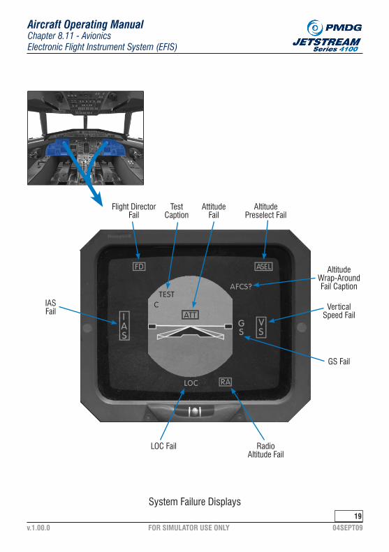
FOR SIMULATOR USE ONLY 04SEPT09v.1.00.0
Chapter 8.11 - AvionicsElectronic Flight Instrument System (EFIS)
Aircraft Operating Manual
19
System Failure Displays
IASFail
Flight DirectorFail
TestCaption
AttitudeFail
AltitudePreselect Fail
AltitudeWrap-AroundFail Caption
VerticalSpeed Fail
GS Fail
RadioAltitude Fail
LOC Fail

FOR SIMULATOR USE ONLY 04SEPT09v.1.00.0
Chapter 8.11 - AvionicsElectronic Flight Instrument System (EFIS)
Aircraft Operating Manual
20
5. Flight Director (FD) Failure
In the event of a FD failure (or during FCC warm-up), a FD warning is dis-played in a red box on the EADI. All FD cues and captions will be removed from the EADI.
· INTENTIONALLY LEFT BLANK ·
6. Comparison Monitoring
The EFIS compares on-side and cross-side system data continuously. If a difference between data exceeds predetermined values, or if data is invalid, the EFIS shows an amber ‘C’ on the EADI, and shows the mis-compared parameter on the EHSI.
The comparison monitor functions for the following parameters:
- Pitch- Roll- Heading- Airspeed- Localizer Deviation- Glideslope Deviation
If a single SG fails, the serviceable SG compares the data on the on-side and cross-side inputs. Any comparison failures will be indicated as de-scribed above.
7. Cooling Fan Failure
In the event of an EFIS cooling fan failure, a CAP (amber) caption will come on.
AV FAN

FOR SIMULATOR USE ONLY 04SEPT09v.1.00.0
Chapter 8.11 - AvionicsElectronic Flight Instrument System (EFIS)
Aircraft Operating Manual
21
H. EFIS Power Supplies
The two EFIS systems are electrically independent for the ASCB data bus that links the two SGs. The failure of one EFIS system does not affect the other system.
The No.1 system is supplied with power from the 28V dc left essential avionic busbar.
The No.2 system is supplied with power from the 28V dc right essential avionic busbar.
A single generator failure will have no effect on the system. A double generator failure will result in a total loss of the EFIS system. Data is available on the No.1 primary altimeter, No.1 RMI, DME indicator and standby instruments.
· INTENTIONALLY LEFT BLANK ·

FOR SIMULATOR USE ONLY 04SEPT09v.1.00.0
Chapter 8.11 - AvionicsAttitude and Heading Reference System (AHRS)
Aircraft Operating Manual
22
2. Attitude and Heading Reference System (AHRS)
A. General
The AHRS is a dual, all attitude inertial sensor installation which provides aircraft attitude, heading and flight data to the EFIS, flight control and weather radar systems. The gyroscopic elements are rate gyros that are accurately aligned with the axes of the aircraft. A digital AHRS reference unit integrates the rate data to obtain heading, pitch and roll. Flux valves provide long term references to the system.
The dual AHRS installation consists of the following equipment:
- Two AHRS reference units- Two flux valves- Two control/compensator units.
The standby attitude and heading instruments are:
- One standby artificial horizon- Two Radio Magnetic Indicators (RMIs)- One standby compass.
B. AHRS Reference Unit
Each AHRS reference unit is accurately installed in the nose equipment bay to within 0.2 degrees of the respective aircraft axes to ensure it provides accurate data. Each AHRS reference unit is cooled by an integral fan.
Two pitch and roll synchro outputs and three heading synchro outputs from each AHRS unit provide data for:
- Pitch and Roll No.1 On-side EFIS- Pitch and Roll No.2 Cross-side EFIS and FDR- Heading No.1 On-side EFIS- Heading No.2 Cross-side EFIS and FCS- Heading No.3 On-side RMI

FOR SIMULATOR USE ONLY 04SEPT09v.1.00.0
Chapter 8.11 - AvionicsAttitude and Heading Reference System (AHRS)
Aircraft Operating Manual
2�
B. AHRS Reference Unit (continued...)
RMI No.1 has a heading output to the FDR. Both AHRS provide dedicated pitch and roll signals to the FCS. The No.2 AHRS is also interfaced to the weather radar system via outputs of pitch and roll which are used to stabilize the radar scanner.
C. Flux Valves and Control/Compensator Units
The flux valves are mounted in the horizontal stabilizers. They interface with the AHRS reference units through the compensator section of the associated control /compensator unit. The control/compensator units are located on the left and right side instrument panels.
D. AHRS Control and Operation
AHRS has four modes of operation: normal and basic for the attitude channel and slaved and DG for the heading channel.
The normal mode utilizes TAS (from the DADCs) to compensate for acceleration induced attitude errors. The loss of TAS causes the AHRS to revert to the basic mode with reduced accuracy. A BASIC caption on the AHRS control unit comes on when TAS is lost.
The slaved mode utilizes input from the flux valves to align the heading outputs of the AHRS reference units. When it is not in the slaved mode, the AHRS oper-ates in the DG mode to produce heading with reduced accuracy and conven-tional gyro.
In the event of a flux valve failure, the DG mode is selected by a pushbutton switch labelled HDG/DG on the AHRS control unit. A SLAVE caption on the AHRS control unit comes on to indicate a slaving failure.
In the DG mode a rotary selector switch on the AHRS control unit, labelled FAST/SLOW, provides a two speed slew facility.
Each AHRS reference unit has a test facility which is activated by a TEST push-button switch on the AHRS control unit.

FOR SIMULATOR USE ONLY 04SEPT09v.1.00.0
Chapter 8.11 - AvionicsAttitude and Heading Reference System (AHRS)
Aircraft Operating Manual
24
D. AHRS Control and Operation (continued...)
When TEST is selected:
- Attitude is indicated as the current attitude reading +10 deg pitch up +20 deg right wing down- Heading turns towards east at 3 deg per sec- All AHRS controllers annunciators come on.
After 2.5 seconds, the indications revert to the individual information.
E. AHRS Indications
With the AHRS and EFIS systems functioning correctly, flight data is displayed as follows:
- No.1 AHRS heading and attitude No.1 EFIS- No.1 AHRS heading No.1 RMI- No.2 AHRS heading and attitude No.2 EFIS- No.2 AHRS heading No.2 RMI
In the event of a total EFIS failure, a heading display is still provided by the RMIs.
F. Standby Attitude and Heading Indication
1. Standby Artificial Horizon
The standby artificial horizon is installed in the centre instrument panel. It contains a gyro and is physically and electrically independent of the AHRS. The display provides an indication of aircraft pitch and roll, and includes an inclinometer. The display shows pitch to 85 deg and roll to 180 deg. Ad-ditionally it provides ILS glideslope and localizer data on two pointers with a ±2 dot scale.
Failure of attitude information (power failure or low gyro speed) is indicated by a red OFF flag on the instrument. When a localizer frequency is set on the No.1 NAV unit and the glideslope or localizer signal is invalid, a red G/S flag and/or LOC flag will show as appropriate.

FOR SIMULATOR USE ONLY 04SEPT09v.1.00.0
Chapter 8.11 - AvionicsAttitude and Heading Reference System (AHRS)
Aircraft Operating Manual
2�
2. Standby Compass
A standby magnetic compass is installed above the main windshield. It is provided with back lighting.
G. AHRS Failure
AHRS failure indications are described in the EFIS reversionary modes and indications. Cross-side AHRS data is obtained by setting the appropriate AHRS rev (reversionary) rotary switch, located on the coaming panel, to the remaining serviceable AHRS.
H. AHRS Power Supplies
Each AHRS reference unit has two 28V dc power inputs, primary and auxiliary. The normal power source is the primary power source. If the primary power source is interrupted, the auxiliary power source is automatically engaged. Each AHRS reference unit is also supplied with a 26V ac from the 26V ac avionic busbars.
The AHRS power supplies are arranged to ensure that at least one AHRU is supplied with power at all times, both on the ground and in flight, and during all operating conditions. To achieve this, the AHRS power supplies are switched by WOW slave relays on the ground.
The standby artificial horizon is normally supplied with power from the avionic emergency busbar.
A switch, labelled STBY INST POWER, located on the centre instrument panel, allows the power supply to the standby artificial horizon (and the standby altimeter) to be switches from the emergency switched avionic busbar to the standby battery busbar. This action is only to be carried out if the aircraft batter-ies become exhausted.
The No.1 RMI is supplied with power from the 28V dc emergency switched avionic busbar whilst the No.2 RMI is supplied with power from the 28V dc right essential busbar.

FOR SIMULATOR USE ONLY 04SEPT09v.1.00.0
Chapter 8.11 - AvionicsAttitude and Heading Reference System (AHRS)
Aircraft Operating Manual
2�
H. AHRS Power Supplies (continued...)
The standby compass does not require electrical power for its operation.
In the event of a single generator failure, the AHRS, standby artificial horizon and the RMIs will continue to operate normally without any reversionary switching. A double generator failure will cause the No.2 AHRS and the No.2 RMI to fail. The No.1 AHRS, standby artificial horizon and the No.1 RMI will continue to be powered.
Each SG can derive data from either AHRS.
Under normal operating conditions, failure of an ac inverter will cause primary attitude and heading to be lost from the appropriate EFIS. Primary heading and attitude are restored on the failed side by selecting the appropriate AHRS rev (reversionary) rotary switch, located on the coaming panel, to the remaining serviceable AHRS.
CAUTION: THE AHRS TAKES 3 MINUTES TO RUN UP AND 2 MINUTES TO RUN DOWN. THE AIRCRAFT MUST NOT BE MOVED DURING THESE RUN UP AND RUN DOWN TIMES OR DAMAGE MAY OCCUR TO THE GYROS.
· INTENTIONALLY LEFT BLANK ·

FOR SIMULATOR USE ONLY 04SEPT09v.1.00.0
System Reversionary Switches
Chapter 8.11 - AvionicsAttitude and Heading Reference System (AHRS)
Aircraft Operating Manual
2�

FOR SIMULATOR USE ONLY 04SEPT09v.1.00.0
The air data system provides dual primary and secondary air data functions and consists of the following equipment:
Chapter 8.11 - AvionicsAir Data System (ADS)
Aircraft Operating Manual
2�
�. Air Data System (ADS)
A. General
- Two Digital Air Data Computers (DADC)- Three pitot heads- Two dual passage static plates (S1-S2)- Two single passage static plates (S3)- One Total Air Temperature probe (TAT)- Two electric primary altimeters- One pneumatic standby altimeter- One pneumatic standby airspeed indicator
Two DADCs provide the primary air data functions. Each DADC is installed in the nose equipment bay.
The DADCs take inputs of static air pressure, pitot (ram) air pressure, tem-perature, baro-correction and stall warning data. From this the DADCs give the following outputs:
B. Digital Air Data Computers
- Pressure Altitude- Baro-corrected altitude- Indicated Airspeed (IAS)- Low airspeed awareness- True Airspeed (TAS)- Vertical Speed (VS)- Maximum Operating Speed (Vmo)- Static and Total Air Temperature (SAT and TAT)- Various airspeed determined switched outputs- Altitude alert.

FOR SIMULATOR USE ONLY 04SEPT09v.1.00.0
Chapter 8.11 - AvionicsAir Data System (ADS)
Aircraft Operating Manual
29
The No.1 DADC is connected to the No.1 pitot head and the No.1 static system. The No.2 DADC is connected to the No.2 pitot head and the No.2 static system.
The TAT interface is provided by a single, dual, element temperature probe. Each DADC is connected to a dedicated element.
Each DADC has two electrically independent ARINC 429 outputs which provides interface to the EFIS, FDR and pressurization systems. Primary altitude for each pilot is provided by an interface between each DADC and its related electric altimeter.
B. Digital Air Data Computers (continued...)
1. Altitude Display and Altitude Alert Indication
Altitude is displayed on electric altimeters located on the right side of each EADI. Each altimeter has a baro-correction knob on its bezel. The baro-cor-rection setting for each DADC is displayed on the associated altimeter in millibars (mb) and inches of mercury (in HG).
The altitude alert function is controlled by the altitude select knob on the co-pilots instrument controller. The set altitude (when set) is shown in cyan digits in the top right corner of each EADI, below the annotation ASEL.
As the aircraft reaches 1000 ft. from the selected altitude (above or below), the selected altitude changes to amber and will flash for 5 seconds. This is accompanied by an amber annunciator on each altimeter flashing and a two second audio warning in the pilots headset and cockpit speakers. The selected altitude and annunciators remain at amber until the aircraft is 250 ft. from the selected altitude.
Within 250 ft. the selected altitude display shows in cyan. If the aircraft de-viates from the selected altitude by more than 250 ft., the selected altitude will flash in amber for 5 seconds and then go steady.
C. Air Data Displays

FOR SIMULATOR USE ONLY 04SEPT09v.1.00.0
Altimeter, Standby Altimeter and Standby Airspeed Indicator
Chapter 8.11 - AvionicsAttitude and Heading Reference System (AHRS)
Aircraft Operating Manual
�0
Altimeter
Standby Altimeter
Standby Airspeed Indicator

FOR SIMULATOR USE ONLY 04SEPT09v.1.00.0
Chapter 8.11 - AvionicsAir Data System (ADS)
Aircraft Operating Manual
�1
1. Altitude Display and Altitude Alert Indication (continued...)
The annunciators on the altimeters will flash and a two second audio warn-ing will be given. The visual warning will continue until the aircraft returns to within 250 ft. of the selected altitude or a new selected altitude is set.
2. Airspeed, Vmo and Low Airspeed Awareness Indication
Airspeed is displayed on the left side of the EADI by digits on a vertical tape and on a rolling drum.
Vmo (Maximum Operating Speed) is displayed on the airspeed tape as a vertical red line, starting at Vmo and extending parallel to the airspeed tape for speeds greater than Vmo. When the airspeed tape indicates Vmo or greater, the digital IAS readout turns red.
Low airspeed awareness is displayed on the airspeed tape as a vertical red line, starting at the airspeed calculated by the DADC to be 1.07 Vs and extending parallel to the airspeed tape for speeds less than this value.
There are four adjustable airspeed bugs which can be displayed. The bugs are selected and set by the IAS control knob on the right instrument remote controller. The airspeed bugs are displayed by symbols adjacent to the ap-propriate speed on the airspeed tape.
Each DADC provides an output at 253 kts (Vmo + 3 kts) to activate an overspeed audio warning. Above altitudes of 17,400 ft. the overspeed warn-ing is limited to 0.525 M (Mmo + 0.005).
3. Vertical Speed Indication
Vertical speed is displayed on the right side of each EADI on a fixed arc scale with digits and a moving pointer.
· INTENTIONALLY LEFT BLANK ·

FOR SIMULATOR USE ONLY 04SEPT09v.1.00.0
Chapter 8.11 - AvionicsAir Data System (ADS)
Aircraft Operating Manual
�2
4. Invalid Air Data Displays
An invalid air data parameter is indicated by a removal of the associated tape and digital readout from the display and replacing it with the param-eters abbreviation (e.g. IAS) surrounded by a red box.
5. True Airspeed and Temperature indication
TAT and TAS are displayed on a dedicated indicator installed in the coam-ing panel. SAT can be set to momentarily display instead of TAT when the switch on the indicator is pushed and held in. The indicator receives TAT, TAS and SAT data from the No.1 DADC only. The input cannot be transferred to No.2 DADC on reversionary selection, when No.1 DADC is unserviceable.
1. Standby Altimeter
A standby altimeter is installed in the centre instrument panel and is con-nected to the No.3 static system. The instrument’s baro-correction is displayed in both mb and inHg
D. Standby Air Data Instruments
2. Standby Airspeed Indicator
A standby airspeed indicator (ASI) is installed in the centre instrument panel below the standby altimeter and it is connected to the No.3 pitot and No.3 static systems.
E. Pitot, Static and TAT Probe
The No.1 pitot head and the TAT probe are mounted on the left side of the for-ward fuselage. The No.2 and No.3 pitot heads are mounted on the right side of the forward fuselage.
There are three static systems with two vents each (to eliminate error caused by differential pressures). The two static plates (each with three vents) are mounted on the forward fuselage (one each side). The pitot heads, TAT probe and static plates are all electrically heated to prevent icing.

FOR SIMULATOR USE ONLY 04SEPT09v.1.00.0
TAS Temperature Indicator
Chapter 8.11 - AvionicsAttitude and Heading Reference System (AHRS)
Aircraft Operating Manual
��

FOR SIMULATOR USE ONLY 04SEPT09v.1.00.0
Chapter 8.11 - AvionicsNavigation System
Aircraft Operating Manual
�4
4. Navigation System
The navigation system contains the following components:
A. General
- Two Integrated Navigation Units with VOR/ILS, ADF, DME and marker sub-systems
- Two Radio Management Units (RMU)- One Clearance Delivery Unit (CDU)- Two DME indicators- Two RMIs- The antenna and coupler systems
Each NAV Unit is installed in the nose equipment bay.
B. Integrated Navigation Unit (NAV Unit)
1. DME
The DME function of the NAV Units can scan two DME channels at the same time. Distance, time-to-go, groundspeed and an alphanumeric station ident can be displayed for two DME stations.
DME data is displayed to each pilot on dedicated DME indicators located on the left and right instrument panels. Each indicator can be selected to any one channel at any one time. The selectable channels are No.1 NAV and No.2 NAV.
DME data for the active frequencies is displayed on the No.1 and No.2 EFIS displays.
2. CDU
Refer to 11-6 for the function, location and controls of the CDU.

FOR SIMULATOR USE ONLY 04SEPT09v.1.00.0
Chapter 8.11 - AvionicsNavigation System
Aircraft Operating Manual
��
Control of the navigation system is achieved by two RMUs, one for each NAV Unit. The RMUs are located on the centre instrument panel, to the left and right of the engine instrument panel.
The RMU is a color CRT display based controller that controls the navigation (NAV) and the communications (COMMS) systems by select keys. Additionally each RMU has the ability to be switched from its on-side NAV Unit to the cross-side NAV Unit.
The RMU has five tuning areas (windows) on its screen (COM, NAV, ADF, ATC and MLS). MLS is not installed in the aircraft and this window remains blank. Each window contains all the information associated with a particular function e.g. the ADF window shows the operating frequency and operating mode. Each window is controlled by a select button and concentric turning controls/knobs.
To change pages, press the PGE switch until the desired page is displayed. To display cross-side information press the 1/2 switch. A second press will return the display to the on-side selection.
C. Radio Management Unit (RMU)
The VOR, ILS and ADF information is primarily displayed on the EFIS, VOR and ADF data from each NAV Unit can be set to display on the RMIs. Navigation data from system 1 is shown on the single bar pointers (RMIs) and bearing No.1 pointer (ball) on the EFIS. Navigation data from system 2 is shown on the double bar pointers (RMIs) and bearing No.2 pointer (diamond) on the EFIS. VOR or ADF selections are made on the EFIS controller for the on-side EFIS and on each RMI for each RMI. Different selections can be made on each EFIS and each RMI.
ILS data from the No.1 NAV Unit is also displayed on the standby artificial horizon and is used as a back-up display in the event of a total failure of the EFIS system.
If a NAV Unit fails, the information from the serviceable NAV Unit is displayed on the cross-side EFIS display by pressing the V/L button on the appropriate EFIS controller.
D. Navigation System Displays and Failure Modes

FOR SIMULATOR USE ONLY 04SEPT09v.1.00.0
RMU (Radio Management Unit) Display
Aircraft Operating Manual
��
TransferSwitch
LineSelect
Switches
LineSelect
Switches
TransferSwitch
FunctionSwitches
TuningKnobs
Chapter 8.11 - AvionicsNavigation System

FOR SIMULATOR USE ONLY 04SEPT09v.1.00.0
Aircraft Operating Manual
DME Indicator��
DME Distance
DME Channel Select Parameter Select
ParameterDisplay
IdentKnots
MinutesNAV Channel
Select (DME1/2)
Chapter 8.11 - AvionicsNavigation System

FOR SIMULATOR USE ONLY 04SEPT09v.1.00.0
E. Navigation System Power Supply
The No.1 navigation system display is supplied with power from the 28V dc emergency switched avionic busbar. The No.2 navigation system is supplied with power from the 28V dc right essential avionic busbar.
If a single generator failure occurs, it will have no effect on the system. In the event of a double generator failure, the No.1 system remains fully functional but the No.2 system is lost.
Chapter 8.11 - AvionicsNavigation System
Aircraft Operating Manual
��
· INTENTIONALLY LEFT BLANK ·

FOR SIMULATOR USE ONLY 04SEPT09v.1.00.0
Chapter 8.11 - AvionicsCommunications and Audio System
Aircraft Operating Manual
�9
�. Communications and Audio System
The communications system consists of the following equipment:
A. General
- Two Integrated Communications Units (Comms Unit) with VHF Communications and ATC transponders
- Two RMUs (shared with the NAV system)- One Clearance Delivery Unit (CDU)- Three Audio Control Panels- PA and Cabin interphone- Two Comms antennas- Two ATC transponder antennas
The ground crew can plug a headset into a connector on the nose gear. The connector is in parallel with the pilot’s audio control panel and gives the ground crew direct communication to the pilot.
Each Comms Unit is installed in the nose equipment bay.
The Comms Units contain the VHF comms and ATC transponder systems and are normally controlled by their respective RMUs. A similar method of cross-side control as the NAV system is provided.
The ATC transponder functions has modes A, C and S. The dual ATC transpon-der system has a lockout to prevent both transponders being active at the same time. Control of the transponder system is via the RMUs.
B. Integrated Communications Unit (Comms Unit)
1. System Control
The Comms Units are normally controlled by the same RMUs that control the NAV units. The Comms Units have their own dedicated windows on the RMUs.

FOR SIMULATOR USE ONLY 04SEPT09v.1.00.0
Chapter 8.11 - AvionicsCommunications and Audio System
Aircraft Operating Manual
40
Audio Control Panel

FOR SIMULATOR USE ONLY 04SEPT09v.1.00.0
Chapter 8.11 - AvionicsCommunications and Audio System
Aircraft Operating Manual
41
Two ACPs, one located on the left and one located on the right instrument panel give selection and control of the audio received and transmitted by each pilot. The ACPs also change the digital sound on the digital bus to analog signals for the headsets and speakers. Each ACP controls on-side facilities (audio, mic signals and speaker).
The ACP allows individual selection of VHF1, VHF2, Interphone (INT) or pas-senger address (PA) for transmissions by buttons on the facia. The buttons are interlocked so only one facility can be selected at a time. Transmission on the selected radio is achieved by the operation of a PTT switch.
Received audio is controlled by rotary push-buttons. The appropriate receiver channel is selected when the required button is out. The push-buttons are not interlocked and can be selected as required. The speaker is controlled by a rotary push-button. Turning the button will adjust the speaker sidetone level. The volume of the headset and the speaker can be individually controlled by volume knobs on the ACP.
If power is lost or an ACP fails, pressing the EMER button on the ACP will cause all emergency VHF (1) comms and VHF (1) nav audio (analog format) to be output directly to the headset.
Each ACP interfaces with the audio warning system. All audio warnings are supplied to the headsets and flight deck speakers simultaneously. Warning audio signals to the speaker cannot be turned off by the speaker switch.
C. Audio Control Panel (ACP)
D. Communication and Audio System Power Supplies
Power for the No.1 and No.2 Radio Communications Units are supplied from the 28V dc unswitched emergency avionics busbar and the 28V dc right essential avionics busbar respectively.
The No.1 ACP is supplied from the 28V dc left essential busbar. The No.2 ACP is supplied from the 28V dc right essential busbar. Both ACPs are also dual-supplied from the 28V dc switched emergency avionics busbar to enable starts and smoke drills.

FOR SIMULATOR USE ONLY 04SEPT09v.1.00.0
Chapter 8.11 - AvionicsCommunications and Audio System
Aircraft Operating Manual
42
D. Communication and Audio System Power Supplies (continued...)
The No.1 and No.2 RMUs are supplied from the 28V dc emergency and the 28V dc right essential busbars respectively.
The CDU is supplied from the 28V dc emergency avionics busbar.
In the event of a single generator failure, all Communications and Audio Systems will be automatically supplied from the functional generator.
In the event of a double generator failure, the No.1 Comms system, all Audio Control Panels and the CDU will remain operational. The remaining components of the No.2 Comms system and the No.1 RMU will not be operational.
E. Clearance Delivery Unit (CDU)
The CDU is located on the left instrument panel and provides a means of tuning the No.1 Comms and NAV units. The controls on the front panel (and their func-tions) are:
- Transfer key: sets the arrow cursor adjacent to the displayed COM or NAV frequency
- SQ On/Off switch: Sets the Comms Unit squelch to on or off- NAV AUDIO On/Off switch: sets the NAV Unit audio to on or off- MODES switch: sets the mode of operation of the CDU. Normal
mode is set with the switch turned clockwise. Emergency mode is set with the switch turned counter-clockwise.
- Tuning Knobs: sets the Comms or NAV Unit frequency selected by the transfer key. The outer knob is used to adjust the whole (main) part of the frequency. The inner knob is used to adjust the decimal portion of the frequency.
· INTENTIONALLY LEFT BLANK ·

FOR SIMULATOR USE ONLY 04SEPT09v.1.00.0
Aircraft Operating Manual
Clearance Delivery Unit4�
Squelch On/Off
COM RadioTuning Caption
NAV RadioTuning Caption
Transfer Key
NORM/EMERGENCYMode Switch
Tuning Knobs
NAV AudioOn/Off Switch
System InstallationCaption
Remote TuneCaption
TuningCursor
Emergency ModeCaption
SquelchCaption
NAV Audio OnCaption
Chapter 8.11 - AvionicsCommunications and Audio System

FOR SIMULATOR USE ONLY 04SEPT09v.1.00.0
Chapter 8.11 - AvionicsCommunications and Audio System
Aircraft Operating Manual
44
F. Passenger Address (PA) System
The PA system provides the following functions:
- Interphone between the pilots and the flight attendant- Cabin announcements from the flight deck- Cabin announcements from the flight attendant- Cabin alerting by the illumination of Fasten Seatbelt and No Smoke
signs- Flight attendant and flight deck call features.
The PA system is linked to the cabin speakers. The system is accessible to the flight crew and flight attendant at all times. The PA system is supplied with 28V dc from the unswitched emergency avionics busbar.
· INTENTIONALLY LEFT BLANK ·

FOR SIMULATOR USE ONLY 04SEPT09v.1.00.0
Chapter 8.11 - AvionicsFlight Control System
Aircraft Operating Manual
4�
�. Flight Control System (FCS)
The Flight Control System (FCS) consists of:
- A Flight Control Computer (FCC)- A Mode Selector.
The FCC is installed under the cabin floor aft of the flight deck bulkhead.
The FCS functions as a Flight Director (FD) and provides lateral and vertical cues on the EADI for the following modes of operation:
A. Flight Control Computer (FCC)
1. Heading (HDG) Mode
Momentary depression of the mode selector HDG button engages the heading mode, if the compass system from the selected pilot is valid. When the mode is engaged, the mode selector button will indicate a green HDG caption. In this mode the command bar will indicate roll commands on the EADIs to achieve the selected heading. The heading mode can be cancelled by capture of another lateral mode, standby mode or momentary reselection of the HDG button.
2. Navigation (NAV) Mode
Momentary depression of the mode selector NAV button causes the FCC to engage either:
- NAV ARM and HDG if the aircraft is outside the 1 dot/5 deg capture zone
- NAV mode if the aircraft is within the capture zone with valid NAV and compass signals.
When the mode is engaged, the mode selector button will indicate an amber ARM or a green CAP caption and the EFIS will indicate a white NAV arm or green NAV caption as appropriate.

FOR SIMULATOR USE ONLY 04SEPT09v.1.00.0
Chapter 8.11 - AvionicsFlight Control System
Aircraft Operating Manual
4�
FD Mode Selector

FOR SIMULATOR USE ONLY 04SEPT09v.1.00.0
Chapter 8.11 - AvionicsFlight Control System
Aircraft Operating Manual
4�
2. Navigation (NAV) Mode (continued...)
In the NAV ARM mode the heading mode provides steering commands to capture an intercept angle set by the heading bug on the EHSIs. When the capture zone is entered, the heading commands are automatically cancelled and the nav mode produces the steering commands.
The navigation mode is cancelled by selection of another lateral mode*, standby mode or momentary reselection of the NAV button.
*NOTE: Back Course at any time. HDG if NAV is captured, though not if NAV is armed when HDG is on as well.
3. Approach (APR) Mode
Momentary depression of the mode selector APR button causes the FCC to engage either:
- NAV ARM, APR ARM and HDG or- APR CAP
The mode engaged depends on the aircraft’s position relative to the ILS. Operation of the APR mode is similar to the NAV mode but existing verti-cal guidance is maintained (and annunciated) until glideslope capture. Glideslope capture is locked-out until localizer capture.
During the approach, glideslope gain is a function of the altitude from the Radio Altimeter (Rad Alt). The gain is reduced as the aircraft gets closer to the glideslope transmitter. If the Rad Alt fails the glideslope gain is controlled as a two stage function as follows:
- Time from glideslope capture (and)- Time from middle marker
The approach mode is cancelled by selection of another lateral mode, standby mode or momentary reselection of the APR button.

FOR SIMULATOR USE ONLY 04SEPT09v.1.00.0
Chapter 8.11 - AvionicsFlight Control System
Aircraft Operating Manual
4�
4. Indicated Airspeed (IAS) Hold
Momentary depression of the mode selector IAS button causes the FCC to engage IAS hold if the DADC output is valid. The mode selector button indicates a green IAS caption and a green caption is presented on the EADIs when the IAS hold mode is engaged. The FCC produces pitch commands to maintain the IAS present when the mode is selected. This is displayed as the vertical deflection of the pitch command bar on the EADIs.
The mode is cancelled by selection of another vertical mode, standby mode or momentary reselection of the IAS button.
5. Vertical Speed (VS) Hold
Operation of the vertical speed mode is the same as the IAS mode except that the aircraft is controlled to the vertical speed present when the mode is selected. Cancellation of the mode is the same as cancellation of the IAS mode.
6. Back Course (BC)
Momentary operation of the mode selector BC button causes the FCC to engage the BC mode or if outside the reverse ILS capture zone it arms the mode. On selection outside the capture zone the BC button will indicate an amber ARM caption and a white BC caption is shown on the EADIs. When the capture zone is entered the mode selector BC button indicates a green CAP caption and the caption on the EADIs indicate a green BC.
Back course approaches can be carried out on any single direction ILS ap-proved for BC operations.
When BC is displayed, glideslope data is locked out and not displayed.
· INTENTIONALLY LEFT BLANK ·

FOR SIMULATOR USE ONLY 04SEPT09v.1.00.0
Chapter 8.11 - AvionicsFlight Control System
Aircraft Operating Manual
49
7. VOR Approach
The VOR approach mode permits precision lateral guidance on an approach to a runway, provided the runway has a VOR located on the extended centre line.
The mode is enabled by momentary depression of the mode selector APR button with the appropriate RMU tuned to the VOR frequency.
8. Altitude (ALT) Hold
Momentary depression of the mode selector ALT button causes the FCC to engage the altitude hold mode, if the DADC data is valid. When the mode is engaged the mode selector button indicates a green ALT caption and a green ALT caption is shown on the EADIs.
The FCC produces commands to maintain the aircraft at the altitude at which the mode is selected. The commands are shown by the vertical deflection of the command bar on the EADIs.
The mode is cancelled by a selection of another vertical mode, standby mode or momentary reselection of the ALT button.
9. Altitude Select (ALT SEL)
Momentary depression of the mode selector ALT SEL button causes the FCC to arm the ALT SEL mode. The mode selector ALT SEL button indicates an amber ARM and ALT ARM is shown on the EADIs.
The desired altitude is selected by the ALT SEL control (on the co-pilot’s instrument controller). The FCC then generates commands for the aircraft to acquire the selected altitude. As the aircraft approaches the selected altitude the mode selector ALT SEL button changes to indicate a green CAP and the EADIs change to show ALT CAP.
On reaching the selected altitude, the altitude hold mode is engaged and vertical commands are given on the command bar to maintain the selected altitude.

FOR SIMULATOR USE ONLY 04SEPT09v.1.00.0
Chapter 8.11 - AvionicsFlight Control System
Aircraft Operating Manual
�0
9. Altitude Select (ALT SEL) (continued...)
The ALT SEL mode cancels any other vertical mode. It can itself be can-celled by selection of another vertical mode, standby mode or reselection of the ALT SEL button.
10. Standby Mode (SBY)
Selection of SBY cancels all previously selected FD modes and removes the command bars from the EADIs. When SBY is pressed (and held) all the mode captions come on and the FD warning flag on the EADIs come into come into view. When SBY is released all the mode captions extinguish and the FD warning flag goes out of view.
11. Go-Around (GA)
Momentary operation of the GA switch on the left POWER lever causes the FCC to engage the GA mode and cancel all other selected modes.
The FCC produces commands to achieve a wing level, approximately 8 deg pitch up.
If autopilot is engaged when GA is selected it will be disengaged.
Selection of any lateral mode commands lateral guidance, but maintains the pitch angle. Selection of a vertical mode cancels the GA mode.
· INTENTIONALLY LEFT BLANK ·

FOR SIMULATOR USE ONLY 04SEPT09v.1.00.0
Chapter 8.11 - AvionicsFlight Control System
Aircraft Operating Manual
�1
Autopilot ModeAP (Green)
Lateral Arm(White)
BC/LOC/NAVVAP/VOR
Lateral Capture(Green)
BC/HDG/LOCNAV/VAP/VOR
Vertical Arm(White)ASL/GS
Vertical Capture(Green)
ALT/ASL/GAGS/IAS/VS
EADI with Autopilot/FD Mode Captions
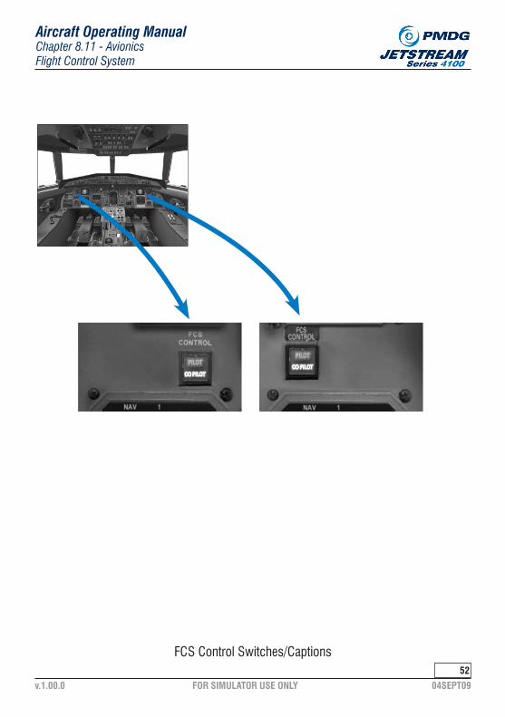
FOR SIMULATOR USE ONLY 04SEPT09v.1.00.0
Chapter 8.11 - AvionicsFlight Control System
Aircraft Operating Manual
�2
FCS Control Switches/Captions

FOR SIMULATOR USE ONLY 04SEPT09v.1.00.0
The mode selector is installed in the centre of the coaming panel. It is configured so that all lateral mode switch/captions are on the top row and all vertical ones on the bottom row.
Indication of mode selection is repeated on the EADIs.
B. Mode Selector
Chapter 8.11 - AvionicsFlight Control System
Aircraft Operating Manual
��
The Flight Control System (FCS) receives navigation, course and air data infor-mation from the NAV Unit (via the Symbol Generator), AHRS and DADC sys-tems, No.1 or No.2 as selected by the pilot/co-pilot.
The switching is controlled by pushbutton switch/annunciators with the split legend “PILOT/CO-PILOT”. The switches are labelled “FCS CONTROL” and are located on the left and right main instrument panels. The annunciation on a black background is PILOT (green) or CO-PILOT (white).
The switching system operates such that when selected to a particular pilot, the air data AHRS and NAV information selected to that pilot’s EFIS is also selected to the flight control system. When the switch is selected to the other pilot, all selected flight director modes are cancelled and must be reselected by the pilot to whom the FCS control has been switched.
C. Control of the Flight Control System
The FCC has internal fault monitoring circuits. In the event of a FCC failure a red FD FAIL warning annunciator is displayed on the top left center of the EADIs. All other FD cues and annunciators are removed from view.
If an autopilot is fitted and the monitoring circuits detect a “hard-over” the auto-pilot is automatically disengaged.
D. Flight Control System Fail Modes
· INTENTIONALLY LEFT BLANK ·

FOR SIMULATOR USE ONLY 04SEPT09v.1.00.0
Chapter 8.11 - AvionicsFlight Control System
Aircraft Operating Manual
�4
The FCS is supplied from the 28V dc left essential avionics and left 26V ac busbar.
In the event of a single generator failure, the FCS will be automatically supplied via the functional generator, and will not be shed.
In the event of a double generator failure the FCS will not be available to the flight crew.
E. Flight Control System Power Supplies
· INTENTIONALLY LEFT BLANK ·

FOR SIMULATOR USE ONLY 04SEPT09v.1.00.0
Chapter 8.11 - AvionicsWeather Radar System
Aircraft Operating Manual
��
�. Weather Radar System (WRS)
The WRS consists of the following equipment:
A. General
- Receiver/Transmitter/Antenna Unit (RTAU)- Weather Radar Indicator (WRI)
Weather radar information is controlled by and displayed on the dedicated WRI, it can also be displayed on the EHSIs.
The WRI is installed in the centre instrument panel. The WRI incorporates the following control and selector switches:
B. Weather Radar Indicator
OFF Sets the radar system to OFF.
STBY Sets the radar system to the standby mode, this inhibits the transmitter and the antenna scan. The system will warm up (45 seconds) during which time it displays WAIT. When warmed up, the system shows STBY
ON Sets the radar system to ON, and starts FP mode.
FP Sets the radar system in the Flight Plan mode. FP is shown on the screen.
TST Sets the radar self test mode. A special test pattern is displayed which al-lows verification of correct system operation. TST is shown on the screen. The radar radiates microwave energy during the test.
TGT Turns on/off the target alert feature. The alert feature advises the crew of potentially dangerous targets directly in front of the aircraft but outside of the selected range. TGT is shown on the screen.
RCT Turns on/off the Rain Echo Attenuation Compensation technique (REACT) mode. The REACT mode compensates for the attenuation of the radar signals as it passes through rainfall. The presence of a cyan field indi-cates areas where compensation is not possible and bad weather may be located.
NOTE: In this simulation, all items in italics are NOT being simulated. They are included for informational purposes only.

FOR SIMULATOR USE ONLY 04SEPT09v.1.00.0
Chapter 8.11 - AvionicsWeather Radar System
Aircraft Operating Manual
��
NOTE: In this simulation, all items in italics are NOT being simulated. They are included for informational purposes only.
B. Weather Radar Indicator (continued...)
WX Sets the radar system to weather detection mode (from GMAP or FP modes)
GMAP Sets the radar system to ground mapping mode. The system enhances returns from ground targets, and reduces returns from weather targets.
RANGE The maximum radar range on the EHSI is selectable by two switches. The switch with the up arrow increases the range, and the switch with the down arrow decreases the range. The selectable ranges are 5, 10, 25, 50, 100, 200 and 300 nm.
AZ Turns on/off the azimuth marks on the display at 30 degree intervals left and right of the aircraft centreline.
SCT Selects either 14 scans per minute (120deg scan) or 28 scans per minute (60 deg scan).
BRT Adjusts the brightness of the display. Clockwise to increase, and counter-clockwise to decrease the brightness.
TILT Sets the antenna tilt angle between ±15deg from the horizontal. When the switch is pulled out auto-stabilizations is switched off.
GAIN When the switches is pushed in, the gain of the receiver is preset (calli-brated) and rainfall rates are shown by the appropriate colour. When pulled out the gain can be varied to enhance the weather picture. When target alert is on, the gain is automatically fixed at the present value.
The WRS is supplied from the 28V dc right essential busbar. A stabilization reference voltage is supplied from the 26V ac right avionics busbar.
A single generator failure will have no affect on the system. A double generator failure will result in the total loss of the WRS display.
C. Weather Radar System Power Supply
· INTENTIONALLY LEFT BLANK ·

FOR SIMULATOR USE ONLY 04SEPT09v.1.00.0
Chapter 8.11 - AvionicsWeather Radar System
Aircraft Operating Manual
��
Weather Radar Indicator
EHSIRangeIncr.
EHSIRangeDecr.

FOR SIMULATOR USE ONLY 04SEPT09v.1.00.0
Chapter 8.11 - AvionicsRadio Altimeter System (Rad Alt)
Aircraft Operating Manual
��
�. Radio Altimeter System (Rad Alt)
The Rad Alt transmitter/receiver is installed beneath the cabin floor, aft of the flight deck bulkhead, on the left side of the fuselage.
The radio altimeter provides an accurate output of height data (above the ground) between 0 and 2500 ft. The height data goes to the EFIS, FDR and FCC (for gain programming).
A test facility is available and is initiated by the selection of test on the left or right EFIS control panel. The on-side Rad Alt display will show 100 ft. and the cross-side Rad Alt display will show RA in red (boxed). If the test is indicated by the coupled side (pilot/co-pilot switch) all FD/AP captions come on, (while the test switch is held in) and the FD goes into standby mode when the test switch is released. The Rad Alt can be tested in the air or on the ground.
A. Rad Alt Transmitter/Receiver
The Rad Alt system is supplied from the 28V dc left essential busbar.
A single generator failure will have no effect on the Rad Alt system. A double generator failure will result in the total loss of the Rad Alt system.
B. Rad Alt System Power Supplies
· INTENTIONALLY LEFT BLANK ·

FOR SIMULATOR USE ONLY 04SEPT09v.1.00.0
Chapter 8.11 - AvionicsAutopilot (AP)
Aircraft Operating Manual
�9
9. Autopilot (AP)
The AP converts the steering commands from the FCS into control surface movement to automatically follow the commanded flight path. It is controlled by an AP controller installed in the centre console to the rear of the engine controls. When the AP is engaged, the FCC provides an automatic electric trim facility.
A. General
The AP controller provides the means of engaging the AP and yaw damper. In addition it also gives manual control of the AP by a TURN KNOB and PITCH WHEEL. The controls on the AP controller are as follows:
B. Autopilot Controller
1. AP ENGAGE Switch/Caption
The AP ENGAGE switch is used to engage the autopilot. Engaging the AP automatically engages the yaw damper (YD). The AP may be engaged with the aircraft in any reasonable attitude and will couple automatically to any FD modes selected on the mode selector upon engagement.
Engagement of the AP causes the AP ENGAGE and YD ENGAGE switch/cap-tion to come on. Subsequent pressing of the switch will cause the AP to disengage but the YD will remain engaged. When the AP is engaged, the automatic electric trim (pitch only) will trim the aircraft if a continuous out-of-trim condition occurs.
2. YD ENGAGE Switch/Caption
When the AP is not engaged, the YD ENGAGE switch can be used to engage the yaw damper only. If the AP is engaged and the YD is disconnected, the AP will not disconnect. The AP must have two valid sources of attitude and one valid source of heading before it can be engaged.
· INTENTIONALLY LEFT BLANK ·

FOR SIMULATOR USE ONLY 04SEPT09v.1.00.0
Chapter 8.11 - AvionicsAutopilot (AP)
Aircraft Operating Manual
�0
3. SOFT RIDE Switch/Caption
The SOFT RIDE mode reduces AP gains whilst still maintaining stability in rough air. When this mode is selected, a green caption in the switch shows ON. SOFT RIDE mode can be used with any FD mode although it will be cancelled on localizer capture. The SOFT RIDE switch should only be used in turbulence.
4. BANK LIMIT Switch/Caption
When in the HDG mode, this facility limits the FD roll command bank. A green caption in the switch shows ON when the mode is on. Bank limits are 5 and 13 deg when heading error is less or more than 10 deg respectively.
5. PITCH Wheel
Rotation of the PITCH wheel results in a change of pitch attitude. The change in pitch attitude is proportional to the rotation and in the direction of the wheel movement.
Movement of the PITCH wheel cancels the ALTitude hold and the ALTitude SELect modes.
When the VS or IAS mode is selected movement of the PITCH wheel changes the air data command reference.
PITCH wheel movement has not effect when the FD has captured the glideslope.
4. TURN Knob
Rotation of the TURN knob out of the detent (centre) position results in a roll command. The roll angle is proportional to and in the direction of rotation of the TURN knob.
The TURN knob must be in the detent position before the AP can be en-gaged. Rotation of the TURN knob cancels any lateral mode selected.

FOR SIMULATOR USE ONLY 04SEPT09v.1.00.0
Chapter 8.11 - AvionicsAutopilot (AP)
Aircraft Operating Manual
�1
The AP OUT switches (instinctive cut-out) are mounted on the pilots’ control columns and are connected to the AP disconnect circuit. They provide a means of disengaging the AP and YD.
If the AP is engaged, the first push of the switch will disconnect the AP and the automatic electric trim.
The second push, (or the first push if the AP is not engaged) will disconnect the YD.
If a switch is pushed and held for more than three seconds, the AP and YD will be disconnected.
C. AP OUT Switches (ICO)
The AP master power switch is located on the coaming panel. The switch is labelled AP/TRIM PWR ON/OFF and controls the power supplies to the AP (FCC, including FD), YD and electric trim.
D. Master Power Switch
A cluster of captions are located on the coaming panel. These indicate as fol-lows:
E. Captions
- AP DISC (red)- YD OFF/TRIM WARN (red-split caption)- TRIM UP/TRIM DN (amber-split caption)- TRIM L/TRIM R (amber-split caption)
· INTENTIONALLY LEFT BLANK ·

FOR SIMULATOR USE ONLY 04SEPT09v.1.00.0
Chapter 8.11 - AvionicsAutopilot (AP)
Aircraft Operating Manual
�2
1. AP DISC
Disconnection of the autopilot causes the AP DISC (red) caption to come on.
The AP DISC caption comes on for two seconds following a pilot induced disconnection, and is continuously following an AP sensed failure condition or AHRS failure. A continuous warning is cancelled by pushing the AP OUT switch.
An output to the Audio Warning System (AWS) causes a ‘cavalry charge’ to sound following an AP disconnect. The horn sounds at the same time (and duration) as the AP DISC caption.
2. YD OFF/TRIM WARN
Following a yaw damper disconnection a YD OFF (amber) caption comes on. The caption follows the same logic as the AP DISC caption, as does the AWS operation of the ‘cavalry charge’.
The TRIM WARN (red) caption comes on to indicate a sustained servo operation in excess of 20 seconds.
3. TRIM captions
The split TRIM UP/TRIM DN and TRIM L/TRIM R (amber) captions (on the coaming panel) come on to indicate that the aircraft is out of trim in the pitch or roll axis. The pitch captions (also on the autopilot controller) show the direction of excessive trim. The roll captions show the direction in which the aircraft must be trimmed to reduce the out of trim condition.
· INTENTIONALLY LEFT BLANK ·

FOR SIMULATOR USE ONLY 04SEPT09v.1.00.0
Chapter 8.11 - AvionicsAutopilot (AP)
Aircraft Operating Manual
��
Each pilot has a split switch/caption which allows either pilot to couple the autopilot and Flight Control System (FCS). The inputs to the Flight Control Com-puter (FCC) are switched to use the appropriate on-side NAV, DADC and AHRS systems.
The split switch/caption will come on either PILOT (green) or COPILOT (white).
If PILOT is selected, the FCS receives data from NAV1, DADC1 and AHRS1. If the DADC or AHRS are selected to the reversionary mode, then number 2 system data is supplied to the FCS. The same logic applies to the selection of COPILOT using the number 2 system and number 1 reversionary selections.
F. Pilot in Command Switch
The autopilot will disengage if any of the following conditions exist:
G. Autopilot Cut-Out
- Pressing the AP ENGAGE button on the controller when it is lit- Pressing either pilot’s AP electric trim switch once- Pressing an AP OUT switch - Pressing the GA switch on left POWER lever- Operation of FCS CONTROL - PILOT/COPILOT switch- Setting AHRS to reversionary mode- Stick shaker operation- CAP “Press to Test”- ICO operation- Manual over-ride by the pilot beyond a point at which a servo
clutch becomes disengaged.
Inputs from the flap system indicate flap movement up or down. These inputs are used to reduce the control gain of the autopilot system during the time that the flaps are in motion.
H. Flaps Input

FOR SIMULATOR USE ONLY 04SEPT09v.1.00.0
Chapter 8.11 - AvionicsAutopilot (AP)
Aircraft Operating Manual
�4
I. Power Supplies
Power to the AP/TRIM master switch is supplied from the 28V dc left essential busbar.
A single generator failure will have no effect on the AP or electric trim functions. A double generator failure will result in the loss of the AP, YD and electric trim functions.
· INTENTIONALLY LEFT BLANK ·

FOR SIMULATOR USE ONLY 04SEPT09v.1.00.0
Chapter 8.11 - AvionicsAutopilot (AP)
Aircraft Operating Manual
��
Autopilot Controller and Control Switches/Captions

FOR SIMULATOR USE ONLY 04SEPT09v.1.00.0
Chapter 8.11 - AvionicsAutopilot (AP)
Aircraft Operating Manual
��
Go-Around Switch
Left PowerLever
Go-AroundSwitch

FOR SIMULATOR USE ONLY 04SEPT09v.1.00.0
Chapter 8.11 - AvionicsClocks
Aircraft Operating Manual
��
10. Clocks
A digital clock is installed on the left and right side of the main instrument panel.
Each clock displays time in hours, minutes and seconds; elapsed time in hours, minutes and seconds up to 99 hours 59 minutes; and flight time in hours, minutes and seconds.
The functions are individually selectable and controlled by two push-buttons located on the facia of each clock. At any time during the flight, the flight time which is started via the weight-on-wheels switch, can be examined without automatically zeroing.
A. General
GMT In 24-hour format.
LOCAL TIME In 24-hour format.
FLIGHT TIME In hours and minutes.
ELAPSED TIME COUNT-UP In minutes and seconds up to 59 minutes and 59 seconds, then hours and minutes up to 99 hours and 59 minutes.
ELAPSED TIME COUNT-DOWN Can be set to countdown anywhere from 1 second to 59 minutes and 59 seconds.
ELAPSED TIME ALARM When the countdown time reaches zero the display flashes.
B. Clock Functions
The left clock is powered from the 28V dc left essential avionic busbar, and the right clock from the 28V dc right essential avionic busbar.
The clocks have an internal alkaline battery to keep the clock circuits ‘alive’ when power is unavailable from the busbars.
C. Power Supplies

FOR SIMULATOR USE ONLY 04SEPT09v.1.00.0
Chapter 8.11 - AvionicsClocks
Aircraft Operating Manual
��
Digital Clock
FOR SIMULATOR USE ONLY 04SEPT09v.1.00.0
Chapter 8.11 - AvionicsGround Proximity Warning System (GPWS)
Aircraft Operating Manual
�9
11. Ground Proximity Warning System (GPWS)
The GPWS uses a Ground Proximity Warning Computer (GPWC) to provide alerts and warnings for inadvertent flight into terrain.
For flight in situations where the pilot must land without full flaps, the GPWS can be desensitized to eliminate unwanted alerts and warnings. This feature can also be utilized during operation at airports where steep approaches or incompatible terrain clearances are involved.
A. General
- ADCs (vertical speed, airspeed)- Navigation receivers (glideslope deviation)- AHRS (roll attitude)- Radio Altimeter (radio height)- Gear and flap systems (aircraft configuration)- EFIS (back course input)- Stall warning system (no callouts during stick shake)
The GPWS utilizes signals from the:
B. System Interfaces
The PILOT/COPILOT FCS CONTROL switches data from No.1 and No.2 sys-tems (ADC, EFIS, NAV receiver, and AHRS) to the GPWC. Audio alerts are output to all crew headsets and cockpit speakers.
· INTENTIONALLY LEFT BLANK ·

FOR SIMULATOR USE ONLY 04SEPT09v.1.00.0
Chapter 8.11 - AvionicsGround Proximity Warning System (GPWS)
Aircraft Operating Manual
�0
- Mode 1 - Excessive Descent Rate- Mode 2 - Excessive Closure Rate to Terrain- Mode 3 - Descent After Take-Off- Mode 4 - Insufficient Terrain Clearance- Mode 5 - Descent Below Glideslope- Mode 6 - Altitude Callouts/Excessive Bank Rate
There are 6 modes of operation:
C. Modes of Operation
1. Mode 1 - Excessive Descent Rate
Mode 1 provides alerts and warnings for high descent rates into terrain. When the outer alert envelope is penetrated, the message “SINKRATE” is given every 3 seconds and the GPWS alert lamps illuminate.
When the inner warning envelope is penetrated, an urgent “PULL UP” message with increased emphasis is given continuously. This warning starts 10 seconds before predicted ground impact. The GPWS lamps are illuminated.
Both the inner and outer warning envelopes are shifted to allow for glideslope deviations above and below the beam centreline to ensure that the warnings are timely and reduce possible nuisance warnings.
2. Mode 2 - Excessive Closure Rate to Terrain
Mode 2 provides 2 types of alerts and warnings to help protect the aircraft from impacting the ground.
a. Mode 2A is activated when:
- Flaps are not in the landing position- GPWS FLAPS OVRD is not selected

FOR SIMULATOR USE ONLY 04SEPT09v.1.00.0
Chapter 8.11 - AvionicsGround Proximity Warning System (GPWS)
Aircraft Operating Manual
�1
a. Mode 2A (continued...)
- The aircraft is not on ILS approach or glideslope mode has been manually cancelled or the aircraft is more than 1.3 dots below the glideslope.
When the warning envelope is penetrated, a “TERRAIN-TERRAIN” message is given once and the GPWS alert lamps are illuminated.
If the envelope penetration continues after the initial message, the normal “PULL UP” message occurs repetitively and the GPWS lamps remain illuminated.
When the envelope is excited, the message will cease but the GPWS lamps remain illuminated until:
- A gain in barometric altitude of 300 ft. or - An accumulation of radio altitude and time equal to 200,000 ft.
seconds occurs.
If during this time the terrain closure rate exceeds 2,000 ft/min the “TERRAIN-TERRAIN” message will be repeated every three seconds. If the warning envelope is re-entered the repetitive “PULL UP” mes-sage will be given and the accumulated combination value towards 300 ft. is reset to zero.
b. Mode 2B is activated when:
- The flaps are in the landing position or GPWS FLAPS OVRD is selected or whilst on an ILS approach and:
- The glideslope function is not cancelled - The aircraft is not more than 1.3 dots below the glideslope- The mode 2B envelope is penetrated the “TERRAIN-TERRAIN”
message is given and the GPWS lamps are illuminated

FOR SIMULATOR USE ONLY 04SEPT09v.1.00.0
Chapter 8.11 - AvionicsGround Proximity Warning System (GPWS)
Aircraft Operating Manual
�2
b. Mode 2B (continued...)
- If the landing gear is DOWN and either flaps are down or GPWS FLAPS OVRD is selected a repetitive “TERRAIN” message is given. Otherwise a repetitive normal “PULL UP” message is given when the previous is complete.
- When the warning envelope is exited the messages cease and the GPWS lamps go out.
3. Mode 3 - Descent After Take-Off
Mode 3 provides alerts for excessive altitude loss after take-off or a go-around from below 245 ft. When a mode 3 alert occurs, a “DON’T SINK” message is given every three seconds and the GPWS lamps illuminate.
Selection of GPWS FLAPS OVRD increases and the allowable altitude loss before the alerts and warnings are given. An additional desensitizing of the envelope occurs above 700 ft. AGL at the rate of 5 ft. additional altitude loss allowed per second.
4. Mode 4 - Insufficient Terrain Clearance
Mode 4 provides 3 types of alerts based on radio altitude, airspeed, and flight mode. These are subdivided into modes 4A , 4B and 4C.
Mode 4A is activated during cruise and approach with the landing gear up, 4B during cruise and approach with the landing gear down and the flaps up or GPWS FLAPS OVRD selected and 4C during take-off. Warnings for 4A, B and C cannot occur simultaneously.
a. Mode 4A
A mode 4A alert occurs when its envelope is penetrated and causes a message to be repeated every 3 seconds and the GPWS lights to illuminate.

FOR SIMULATOR USE ONLY 04SEPT09v.1.00.0
Chapter 8.11 - AvionicsGround Proximity Warning System (GPWS)
Aircraft Operating Manual
��
a. Mode 4A (continued...)
If the aircraft speed is below 168 kts the message is “TOO LOW GEAR”. Above 168 kts is “TOO LOW TERRAIN”.
b. Mode 4B
The mode 4B envelope is selected whenever the landing gear is down below 750 ft. AGL or GPWS FLAPS OVRD is selected. If the mode 4B envelope is penetrated the GPWS lights illuminate and one of 3 mes-sage is given.
Flaps retracted and the landing gear down and airspeed less than shown on the envelope and GPWS FLAPS OVRD not selected, a “TOO LOW FLAPS” message is repeated every three seconds.
Landing gear up, having previously been down below 700 ft. AGL to select this mode initially and; airspeed below the figure in the enve-lope a “TOO LOW GEAR” message is repeated every 3 seconds.
If the airspeed is above the figure in the envelope and GPWS FLAPS OVRD is not selected, a “TOO LOW TERRAIN” message is repeated every 3 seconds.
b. Mode 4C
Mode 4C is based on a minimum terrain clearance, or floor, that increases with radio altitude during take-off. The floor is 3/4’s of the highest value of radio altitude that has occurred during take-off. The mode 4C radio altitude on take-off continues until the approach mode is activated or until the radio altitude decreases below 30 ft. The up-per limit expands with airspeed. If a go-around is being performed, the warning floor is enabled at 245 ft.
· INTENTIONALLY LEFT BLANK ·

FOR SIMULATOR USE ONLY 04SEPT09v.1.00.0
Chapter 8.11 - AvionicsGround Proximity Warning System (GPWS)
Aircraft Operating Manual
�4
b. Mode 4C (continued...)
If the aircraft descends below accumulated floor value, which will occur if the aircraft commences a descent after take-off, or the terrain rises below the aircraft at a steeper gradient than the aircraft is climb-ing, the “TOO LOW TERRAIN” message is repeated every 3 seconds and the GPWS lamps illuminate. The alert and warnings continue until the aircraft has gained sufficient clearance from the terrain.
5. Mode 5 - Descent Below Glideslope
Mode 5 provides alerts and warnings for excessive glideslope deviation below the beam on front course ILS approaches. Depending on the sever-ity of the deviation, 2 levels of “GLIDESLOPE” message are given. The low volume alert is a ‘soft’ alert and the normal volume alert is referred to as a ‘hard’ alert. The time between messages is variable according to deviation and radio altitude. It decreases as the severity of the mode 5 condition increases.
In addition to the messages G-SLOPE warning lights illuminate with mode 5.
For simultaneous mode 5 and mode 1 alert conditions, “GLIDESLOPE”, pause, “SINKRATE” messages are repeated every 3 seconds.
6. Mode 6 - Altitude Callouts/Excessive Bank Rate
a. Altitude Callouts
“MINIMUMS-MINIMUMS” is called once per approach as the aircraft descends through the decision height (DH) altitude set on the indica-tor. For approaches when minimums callout is not required the DH setting should be se below 50 ft.
No GPWS lamps illuminate with this callout. If the callout cannot be made due to existing messages of a higher priority, the callout is latched off until the aircraft climbs through 925 ft AGL, when it is reset (no callout made).
FOR SIMULATOR USE ONLY 04SEPT09v.1.00.0
Chapter 8.11 - AvionicsGround Proximity Warning System (GPWS)
Aircraft Operating Manual
��
a. Excessive Bank Angle
A “BANK ANGLE” callout warns against excessively high bank angles at low altitude. Excessive roll rate advances the warning. The callout is repeated every 3 seconds until the flight condition is corrected.
No GPWS lights are illuminated with this callout.
GPWS/GPWC can be manually self tested on the ground by operating the GPWS test switch on the systems test panel (right console).
D. Self Test
The GPWC receives 28V dc from the avionics left essential busbar via a 1 amp circuit breaker.
E. GPWS Power Supplies
GPWS and GPWC are activated when the power supplies are available and deactivated when the power supply is removed from the avionics left essen-tial busbar. There is no separate/dedicated on/off switch. The six modes are activated when their envelopes are penetrated and deactivated when the alert situation no longer exists in accordance with the mode descriptions. The high-est priority warning is always the one broadcast when more than one warning is activated.
F. GPWS Control and Indication
1. Indications
On the left and right coaming panels there are identical indications and control buttons for the GPWS.
GPWS illuminates in accordance with the warnings described in the mode descriptions.
G-SLOPE illuminates with the warnings of glideslope deviation in mode 5 unless it is inhibited.

FOR SIMULATOR USE ONLY 04SEPT09v.1.00.0
Chapter 8.11 - AvionicsGround Proximity Warning System (GPWS)
Aircraft Operating Manual
��
1. Indications (continued...)
GPWS FLAPS OVRD illuminates when the caption is pressed to desensi-tise the system. This allows operations which would require the GPWS to be completely deactivated whilst retaining the GPWS functions. The effects of GPWS FLAPS OVRD are described in the mode operations.
GSLOPE INHIBIT illuminates when the caption is pressed and inhibits the glideslope alerts and warnings associated with mode 5.
A CAP (amber) caption illuminates when the power supplies to the GPWC fail or a fault is detected in the GPWS.
GPWSFAIL
· INTENTIONALLY LEFT BLANK ·

FOR SIMULATOR USE ONLY 04SEPT09v.1.00.0
Chapter 8.11 - AvionicsGround Proximity Warning System (GPWS)
Aircraft Operating Manual
��
GPWS Captions

FOR SIMULATOR USE ONLY 04SEPT09v.1.00.0
Chapter 8.11 - AvionicsTraffic Alert and Collision Avoidance System (TCAS)
Aircraft Operating Manual
��
12. Traffic Alert and Collision Avoidance System (TCAS)
The TCAS provides the flight crew with data on possible airspace danger from other aircraft.
The TCAS receives external data from other aircraft transponders. It uses this data to calculate the range, the altitude and the bearing of the other aircraft. From this calculated data, the TCAS informs the flight crew of the possible collision danger (from other aircraft) and the necessary avoidance measures to be taken.
TCAS can only interrogate aircraft that are fitted with Air Traffic Control Radio-Beacon System (ATCRABS) transponders (mode C or A/C) or mode S tran-sponders.
A. General
- Control and operation of the system from the radio management unit (RMU)
- Position of the landing gear from the extension and retraction system
- Aircraft-on-ground from the AOG switching system- Airspeed from the Air Data System (ADS)- Attitude valid from the Flight Director system (FD)- Attitude and heading from the Attitude and Heading Reference
System (AHRS)- Radio Altitude from the Radio Altitude system (Rad Alt)- Mode S transmitter signal from the ATC system- Audio-warning inhibit signal from the GPWS
The TCAS gets data about the:
B. System Interfaces

FOR SIMULATOR USE ONLY 04SEPT09v.1.00.0
Chapter 8.11 - AvionicsTraffic Alert and Collision Avoidance System (TCAS)
Aircraft Operating Manual
�9
The TCAS sends data about the position of other aircraft to the:
- Audio integrating system- Electronic Flight Instrument System (EFIS)
C. Modes of Operation
1. Manual Control
The RMU gives manual control of the modes of operation of the TCAS. The set modes of operation, controlled from the RMU ATC/TCAS control page, are the:
- ABOVE/NORMAL/BELOW- TCAS RANGE- INTRUDER ALTITUDE- TA DISPLAY
a. ABOVE/NORMAL/BELOW
The ABOVE/NORMAL/BELOW section of the control page, allows the flight crew to set the altitude display on EFIS, at the display limits that follow:
- ABOVE: 7000 ft. above and 2700 ft. below the aircraft
- NORMAL: 2700 ft. above and below the aircraft
- BELOW: 2700 ft. above and 7000 ft below the aircraft
b. TCAS RANGE
The TCAS section of the control page, allows the flight crew to set the TCAS range display on the EFIS. The ranges are 6nm, 12nm, 20nm or 40nm. The 6nm and the 12nm ranges also show a 2nm dotted range- ring on the display.

FOR SIMULATOR USE ONLY 04SEPT09v.1.00.0
Chapter 8.11 - AvionicsTraffic Alert and Collision Avoidance System (TCAS)
Aircraft Operating Manual
�0
c. INTRUDER ALTITUDE
The INTRUDER ALTITUDE section of the control page allows the flight crew to set either REL (relative) or FL (flight level) target acquisition on the EFIS.
When REL is set, the altitude of the target aircraft is shown in relation to own aircraft altitude. When FL is set, the altitude of the target aircraft is shown as a flight level.
NOTE: If FL is set on the RMU, the EFIS display returns to a REL display after 15 seconds.
d. TRAFFIC ADVISORY (TA) DISPLAY
The TA section of the control page allows the flight crew to set either the AUTO or MANUAL modes of operation.
1. In the AUTO mode, no TCAS targets are displayed on the EFIS until a TA intruder aircraft is detected. The TA intruder aircraft is then displayed on the EFIS. At the same time, all other TCAS traffic (proximity or non-threat) are also displayed.
2. In the MANUAL mode, all TCAS targets (maximum of 12) are displayed on the EFIS.
· INTENTIONALLY LEFT BLANK ·

FOR SIMULATOR USE ONLY 04SEPT09v.1.00.0
Chapter 8.11 - AvionicsTraffic Alert and Collision Avoidance System (TCAS)
Aircraft Operating Manual
�1
2. Aircraft Classification
TCAS identifies and displays the intruder aircraft on EHSI as:
- NON-THREAT- PROXIMITY- TRAFFIC ADVISORY
a. Non-threat Traffic Symbol
Non-threat aircraft are shown on the EFIS as an open blue diamond. The data tags (adjacent to the symbol) show the altitude and climb or descent direction of the non-threat aircraft.
b. Proximity Traffic Symbol
Proximity aircraft are shown on the EFIS as a filled blue diamond. The filled diamond shows the distance and bearing of the aircraft. The data tags (adjacent to the symbol) show aircraft altitude and climb or descent direction of the aircraft.
c. Traffic Advisory Symbol
Traffic advisory aircraft are shown on the EFIS as a filled amber circle. Shown adjacent to the symbol is the altitude data tags and a climb or descent arrow. At the same time, the audio warning ‘TRAFFIC TRAFFIC’ is sent to the flight crew headsets and the flight deck speakers.
· INTENTIONALLY LEFT BLANK ·

FOR SIMULATOR USE ONLY 04SEPT09v.1.00.0
Chapter 8.11 - AvionicsTraffic Alert and Collision Avoidance System (TCAS)
Aircraft Operating Manual
�2
Radio Management Unit (RMU) TCAS Control
TransferSwitch
LineSelect
Switches
LineSelect
Switches
TransferSwitch
FunctionSwitches
TuningKnobs
TCAS Control Page Selected TCAS Contros on RMU

FOR SIMULATOR USE ONLY 04SEPT09v.1.00.0
Chapter 8.11 - AvionicsTraffic Alert and Collision Avoidance System (TCAS)
Aircraft Operating Manual
EHSI with TCAS Display��
Non-Threat Traffic (Open Blue
Diamond)
Proximity Traffic(Solid Blue Diamond)
SetRange
TCAS FailureMessages:-
TCAS FailTCAS TestTA OnlyTCAS Off
Traffic Advisory(Filled Amber Circle)

FOR SIMULATOR USE ONLY 04SEPT09v.1.00.0
Chapter 8.11 - AvionicsTraffic Alert and Collision Avoidance System (TCAS)
Aircraft Operating Manual
�4
e. Non-Altitude Reporting (NAR) Aircraft Data
Intruder aircraft whose transponders reply in a mode A (non-altitude reporting) are shown on the EFIS as a TA symbol with no data tags.
f. No-Bearing Data
When the system has range but no bearing information to other aircraft the data is displayed in the lower right corner of the EHSI display.
g. TCAS Failure
TCAS failures are indicated on the EFIS by removal of the TCAS symbol (as appropriate) and an annunciated fail message ‘TCAS FAIL’
NOTE: TCAS cannot provide an alert for traffic conflicts with aircraft without operating transponders.
D. Threshold Warnings
1. TCAS divides the airspace around the aircraft into seven variable-sensitivity threshold levels, dependant on the aircraft altitude. These threshold levels give the threat level to the aircraft and generate the related traffic advisory warnings.
2. If another aircraft is 25 seconds (lower threshold) or 45 seconds (upper threshold) from the Closest Point of Approach (CPA) the system identifies the aircraft as an intruder. The intruder aircraft is shown on the EFIS as a TA display. At the same time, the traffic-advisory audio warning is sent to the flight crew headsets and the flight deck speakers.
3. If the intruder is 20 seconds (lower threshold) or 35 seconds (upper threshold) from the CPA, the system identifies the aircraft as a threat. The threat aircraft is shown on the EFIS as a RA display. At the same time the resolution advisory audio-warning is sent to the flight crew headsets and the flight deck speakers. The audio messages gives the recommended vertical change of altitude (shown on the VSI) to prevent a collision with the threat aircraft.

FOR SIMULATOR USE ONLY 04SEPT09v.1.00.0
Chapter 8.11 - AvionicsTraffic Alert and Collision Avoidance System (TCAS)
Aircraft Operating Manual
��
F. TCAS Power Supplies
The TCAS receives 28V dc from the avionics left essential busbar via a 7.5 amp circuit breaker.
E. System Self Test
TCAS sends a self-test complete or self-test fail signal to the audio interrogating system. On conclusion of a successful self-test, the audio message TCAS SYS-TEM TEST OK is given. If a failure is detected, the audio message TCAS SYSTEM TEST FAIL is given.
G. Validity Interfaces
The processor monitors the valid data inputs to the system from the other air-craft systems. If the processor detects a fault (in the data), a TCAS FAIL caption is shown on the EFIS.
· INTENTIONALLY LEFT BLANK ·

FOR SIMULATOR USE ONLY 04SEPT09v.1.00.0
Chapter 8.11 - AvionicsEmergency Locator Transmitter (ELT)
Aircraft Operating Manual
��
1�. Emergency Locator Transmitter (ELT)
The ELT system consists of the following items:
A. General
B. System Operation
- An ELT- An ELT antenna- A remote switch panel
The ELT is an automatically activated emergency location device that transmits a sweeping audio signal on the VHF and UHF emergency frequencies. The ELT will operate for approximately 50 hours. The ELT is located in the top of the rear equipment bay and the antenna is mounted in the top surface of the bay, to the left of the fin. The remote switch panel is mounted on the main instrument panel. The ELT must not be used except for emergencies.
1. Electrical Power Supply
The ELT has an internal battery pack (sealed non-rechargeable type) that can be replaced when the ELT is removed from the aircraft. 28V dc from the right essential busbar is used to provide manual control of the ELT from the remote switch panel.
2. Automatic Operation
The ELT will automatically switch on and transmit when it is subjected to a 2 g force. The ELT can be manually reset from the switch on the front or from the remote switch panel.
3. Manual Operation (from remote switch panel)
The remote switch panel has a two position rocker switch, annotated ARM and ON, and an indicator light. When the switch is set to ON the ELT is turned on. When the switch is set to ARM, the ELT will operate automati-cally in the event of a crash.

FOR SIMULATOR USE ONLY 04SEPT09v.1.00.0
Chapter 8.11 - AvionicsEmergency Locator Transmitter (ELT)
Aircraft Operating Manual
��
3. Manual Operation (from remote switch panel) (continued...)
The switch should be left in the ARM position. When the ELT is transmit-ting the indicator light will flash.
· INTENTIONALLY LEFT BLANK ·

FOR SIMULATOR USE ONLY 04SEPT09v.1.00.0
Chapter 8.11 - AvionicsFlight Management System (FMS)
Aircraft Operating Manual
��
14. Flight Management System (FMS)
A. General
1. The GNS-XLs Flight Management Computer (FMC) is an integrated system designed to give the flight crew centralized control for the navigation sen-sors, computer-based flight planning, fuel management and communica-tions management. It has a full-color flat-panel LCD display, alpha-numeric and function keys, a Global Positioning Sensor (GPS), and a navigation data base All these are housed in a panel-mounted Control Display Unit (CDU).
2. The GNS-XLs Flight Management System is approved for enroute and terminal operations in accordance with AC 20-138. The GNS-XLs Flight Management System is approved for enroute and terminal operations when RAIM is available or unavailable. The system, while capable of flying instru-ment approaches, is currently not approved for approach procedures in the J-41. In addition to the global positioning sensor, position information is accepted from VOR/DME radios The navigation sensor information inputs are blended to form a single composite position. Accuracy of the compos-ite position is enhanced by using the best characteristics of each type of sensor. The internal GPS sensor has excellent overall characteristics and will usually be the dominant sensor during blending. However, when RAIM is available, the GPS sensor is the sole contributor to the position. If the FMS fails enroute, pilots must navigate via VORs and/or radar vectors
NOTE: The Honeywell EDZ-805 Electronic Flight Instrument System, as installed, does not support the scaling specified in TSO C129 for approach opera-tions. Many airlines are not currently approved to use the GNS-XLs Flight Management System for instrument approach procedures.
NOTE: RAIM (Receiver Autonomous Integrity Monitoring) is a quality factor used to determine the accuracy of the GPS position. It is an internal function of the GPS receiver and determines the accuracy of its navigation solution.
· INTENTIONALLY LEFT BLANK ·

FOR SIMULATOR USE ONLY 04SEPT09v.1.00.0
Chapter 8.11 - AvionicsFlight Management System (FMS)
Aircraft Operating Manual
�9
3. The navigation database is updated on a 28-day cycle by way of memory card. The worldwide database contains over 50,000 waypoints, navaids and airports It also contains altitudes at appropriate waypoints, SID, STAR, AIRWAY and APPROACH procedures. In addition to this database, the memory can store up to 999 operator-generated waypoints.
4. Additional capabilities of the FMS include direct navigation from present position to any waypoint with trip plan and fuel plan functions available.
5. There is capability for creating a PSEUDO-VORTAC (selected course) to any waypoint and establishing an offset parallel course. The NAV radios can be tuned through the system or by using the individual control head.
B. AFIS
· INTENTIONALLY LEFT BLANK ·
NOTE: AFIS features are not modelled in this simulation.

FOR SIMULATOR USE ONLY 04SEPT09v.1.00.0
Chapter 8.11 - AvionicsFlight Management System (FMS)
Aircraft Operating Manual
90
C. Waypoints
1. Due to the way the FMS database is structured, waypoints must have unique identifiers. However, some duplicate ICAO identifiers exist for more than one waypoint. In these cases, the waypoint identifiers are renamed in the database. Two naming conventions are used, one for four-character identifiers and one for five-character identifiers.
2. Four-character waypoints keep the first four characters and the last two characters of the ICAO airport identifier, as shown in the following example:
1) ‘MAl 1” at KPRC becomes “MAl 1 RC” in the database.
3. Five-character waypoints keep the first five characters and add the last character of the ICAO airport identifier, as shown in the following example:
1) “MA27L” at KOAK becomes “MA27LK” in the database.
D. NDBs
1. NDBs stored in the internal database are listed in Jeppesen publications with a two or three-digit identifier. To distinguish these NDBs from VHF navaids, you must add an “NB” suffix to the database identifier, as shown in the following example:
1) ‘lA” NDB becomes “IANB” in the database.
E. Intersections
1. Most intersection waypoint identifiers consist of five letters. However, three, four and five-letter and number combinations exist. To access these waypoints, enter the identifier from the Jeppesen chart.
· INTENTIONALLY LEFT BLANK ·

FOR SIMULATOR USE ONLY 04SEPT09v.1.00.0
Chapter 8.11 - AvionicsFlight Management System (FMS)
Aircraft Operating Manual
91
F. Offset Waypoint
1. An offset waypoint is a set of coordinates determined by a selected radial and distance from a previously defined or database waypoint. An “*“ following the parent waypoint denotes an offset waypoint. More than one offset waypoint is allowed from one parent using ~ ~ ~ etc., as identify-ing notation.
2. The entries required to establish an offset waypoint are the radial from the parent waypoint in degrees and tenths of degrees, along which the offset is established and the distance from the parent waypoint to the offset way-point.
G. Definitions
1. The following general terms and abbreviations are used:
a. Field
1) A line of information.
b. Cursor
1) Yellow rectangular box placed over a field to enter or change the information in that field. The cursor is normally out of view but will reappear by depressing the Line Select keys on either side of the screen When information is entered into a field and the ENTER key depressed, the cursor will move to the next usable field or disappear from the screen when the last field is entered. Blinking of a field indicates that the computer has not accepted the entry because of unreasonable or invalid information.
· INTENTIONALLY LEFT BLANK ·

FOR SIMULATOR USE ONLY 04SEPT09v.1.00.0
Chapter 8.11 - AvionicsFlight Management System (FMS)
Aircraft Operating Manual
92
c. Page
1) Information is arranged in sections and subsections, much like chapters in a book. Individual screen displays are referred to as pages. Each section is selected by depressing the appropriate Display Selector key located at the top of the FMC. Each subse-quent push of the key will select the next page of that section. A subsection page is selected by depressing the Line Select key next to the topic desired, then depressing the ENTER key The PRy, NXT or BACK keys can be used to move forward or back-ward through pages of a subsection. If the first page of a subsec-tion is displayed, the BACK key will exit the subsection.
d. Waypoint
1) A navigation point, consisting of 1 to 6 alpha-numeric characters, that has a specific latitude and longitude.
· INTENTIONALLY LEFT BLANK ·

FOR SIMULATOR USE ONLY 04SEPT09v.1.00.0
Chapter 8.11 - AvionicsFlight Management System (FMS)
Aircraft Operating Manual
9�
H. Controls And Indicators
a. ON
1) Depress and release the ON key to apply power to the system. There is a warm-up period of approximately 30 seconds. The display illumi-nation will initially be set at 75% of full bright.
2) Depressing the ON key for approximately three seconds will initiate the system power-off sequence. During the sequence, the display will show SYSTEM TURNING OFF. This is to prevent inadvertent system shutdown.
b. BRT (brightness)
1) The BRT key is not functional in this simulation. In the real aircraft, the BRT key is used to change the illumination of the display. This key is also used for parallax adjustment of the Line Select keys. The illumi-nation of the front panel and keyboard is normally controlled through the aircraft panel lighting control.
c. MSG (message key/annunciator)
1) The MSG annunciator will flash to alert the operator that a message needs to be viewed on one of the SYSTEM MESSAGES or SENSOR MESSAGES pages.
2) Depressing the MSG key will display the message page. The newest message will be indicated with a flashing asterisk to the left of the message. If the message requires that some action be taken by the operator, the MSG annunciator will remain on steadily until the action is completed. If no action is required, the MSG annunciator will extin-guish when the message page is exited.
· INTENTIONALLY LEFT BLANK ·

FOR SIMULATOR USE ONLY 04SEPT09v.1.00.0
Chapter 8.11 - AvionicsFlight Management System (FMS)
Aircraft Operating Manual
94
d. Alpha Keys
1) The alpha keys are used to enter the 26 letters of the alphabet as well as the asterisk (*) key.
e. Numeric Keys
1) The numeric keys are used to enter numbers 01 to 9, # and ±.
f. HOLD key
1) If the cursor is positioned over a waypoint identifier and it is appro-priate to program a holding pattern at that waypoint, depressing the HOLD key accesses the holding pattern page.
2) If the cursor is not displayed, depressing the HOLD key accesses the POSITION FIX page, and is used for position updates and verification, as well as for entering the primary navigation mode.
g. BACK Key
1) The BACK key is used to erase errors and page backward when the cursor is not displayed. It can also be used to change data in a field if the cursor is present.
h. SP (space) key
1) The SF key is used to enter a space when entering a message on an AFIS page.
i. ENTER Key
1) When the ENTER key is depressed, data is entered into computer memory.
· INTENTIONALLY LEFT BLANK ·

FOR SIMULATOR USE ONLY 04SEPT09v.1.00.0
Chapter 8.11 - AvionicsFlight Management System (FMS)
Aircraft Operating Manual
9�
j. Display Selector Key
1) NAV (Navigation), VNAV (Vertical Navigation), AFIS (Airborne Flight Information System), FPL (Flight Plan), PLAN (Planning), HDG (Head-ing), TUNE (Radio Tuning) and D (Direct) are used to select the pages pertaining to that particular section. The first page of a section is dis-played when a Display Selector key is pressed. With each subsequent press of the key, the next sequential page will be displayed.
k. PRV (previous) Key
1) The PRV key is used to display the previous page of a section or subsection. This key also allows the operator to remain in a section or subsection by looping from the first to the last, and back to the first page of that section or subsection.
l. NXT (next) Key
1) The NXT key is used to display the next page of a section or sub-section. This key also allows the operator to remain in a section or subsection by looping from the first to the last, and back to the first page of that section or subsection.
m. Line Select Keys
1) These keys are used to place the cursor in the field next to that key. Each line select key controls 2 lines of text. White symbols (< or >) displayed on either side of the display indicate active line select keys for each individual page.
n. AFIS Section Selection
1) INOP
· INTENTIONALLY LEFT BLANK ·

FOR SIMULATOR USE ONLY 04SEPT09v.1.00.0
Chapter 8.11 - AvionicsFlight Management System (FMS)
Aircraft Operating Manual
9�
o. Colors
1) The CDU displays are color-coded to assist the operator in recog-nizing information. The following is a list of these colors and their meanings:
(1) Magenta: Lateral TO waypoint, vertical TO waypoint, and TO waypoint.
(2) Yellow: FROM waypoint, caution messages and data entered, but not yet accepted by the computer.
(3) Cyan: Date and times, tuned frequencies or codes and altitudes.
(4) Green: Navigation and fuel data, general page data.
(5) White: Page titles and prompts.
(6) Red: Warnings.
(7) Blue: Waypoint numbers.
I. Messages
1. System, sensor and AFIS messages are displayed on separate pages in the MESSAGE section. They are accessed by depressing the MSG key. The MESSAGE section will consist of as many pages as are required to display current messages. The MSG key is used to cycle through the AFIS, system and sensor message pages, and to return to the page that was displayed before accessing the MESSAGE section.
2. NXT, PRV and BACK keys can be used to page forward and backward through the message pages.
3. System messages describe the system’s operation with all related aircraft systems Sensor messages describe the operational status of each naviga-tion sensor.

FOR SIMULATOR USE ONLY 04SEPT09v.1.00.0
Chapter 8.11 - AvionicsFlight Management System (FMS)
Aircraft Operating Manual
9�
4. In most instances, when new messages are added, the message light will flash, and a flashing yellow asterisk will appear adjacent to the new mes-sage.
5. A list of these messages is located in Chapter 2 of the GNS-XLs FMS Operator’s Manual.
J. Annunciators NOTE: This feature is not implemented in this simulation.
K. Operating Procedures
1. The FMS provides the flight crew with navigation and database information, which can result in a significant workload reduction. Full workload reduc-tion is only obtainable when the system is operated as intended, including proper preflight initialization and in-flight changes. The FMS must always be monitored after any in-flight changes.
2. In general, the FMS should be used to provide the best possible navigation-al picture to the flight crew while keeping workload to a minimum in con-gested areas. When abnormal or emergency situations arise, the flight crew must decide whether the time and attention required to modify the FMS would compromise flight safety. In the event that flight plan changes occur at inopportune times or in areas of high traffic density, the crew should not hesitate to use conventional navigation and flight path control methods.
· INTENTIONALLY LEFT BLANK ·

FOR SIMULATOR USE ONLY 04SEPT09v.1.00.0
Chapter 8.11 - AvionicsFlight Management System (FMS)
Aircraft Operating Manual
9�
L. FMS Initialization
1. The FMS initialization is normally done by the First Officer.
2. The Allied Signal Aerospace Operator’s Manual, Global Wulfsberg GNS-XLs Flight Management System, Manual Number 006-08845-0000, Revision 7, dated Jan/96, or a later approved revision, must be available to the flight crew. Prior to flight, the crew must verify (by the Program Verification read-out on the bottom of the CDU initialization page) that Part Number 17960-0102 SMO4 (or later approved software modification) is displayed.
3. The Internal Data Base (IDB) must be updated to the latest revision every 28 days. Updating may be accomplished with an Allied Signal update card. Out-of- date data shall not be used.
4. When latitude/longitude data, transferred from the IDB, is displayed on the CDU, the flight crew must assure that it is a reasonable position for the requested identifier.
a. Date, GMT, and Database ValidityNOTE: FSX date/time settings are being used

FOR SIMULATOR USE ONLY 04SEPT09v.1.00.0
Chapter 8.11 - AvionicsFlight Management System (FMS)
Aircraft Operating Manual
99
b. Position Initialization
1) The initialization position should be the airport reference point Once the INITIALIZATION page appears, and after a brief delay, the IDENT field normally prefills with the ICAO ident of the airport closest to the aircraft position after shut-down, provided that the aircraft’s real position and system position were the same at system shutdown.
a) IDENT ..................................................................... INSERT
(1) If necessary, enter the letters of the departure airport’s ICAO identifier. The airport reference point coordinates will be displayed below.
a) POSITION COORDINATES ......................................... VERIFY
(1) Verify that the coordinates highlighted by the cursor on the INITIALIZATION page are correct.
· INTENTIONALLY LEFT BLANK ·

FOR SIMULATOR USE ONLY 04SEPT09v.1.00.0
Chapter 8.11 - AvionicsFlight Management System (FMS)
Aircraft Operating Manual
100
c. Company Flight Plan Route Entry (Stored Routes)
1) This page comes up immediately after the initialization page, or can be accessed by paging the FPL pages. These stored routes cannot be modified unless the route is the ACTIVE FLIGHT PLAN. Any modifications made at this time will not be stored as a company stored route.
a) ORIGIN .................................................................... VERIFY
(1) The page should come up with the origin already entered for the initialization page. If it does not, use the line select keys to highlight the ORIGIN field, and then enter the four-letter identifier.
· INTENTIONALLY LEFT BLANK ·

FOR SIMULATOR USE ONLY 04SEPT09v.1.00.0
Chapter 8.11 - AvionicsFlight Management System (FMS)
Aircraft Operating Manual
101
b) DESTINATION .......................................................... INSERT
(1) Use the line select keys to highlight the DESTINATION field and then enter the four-letter identifier.
c) VIA .......................................................................... INSERT
(1) You must enter the VIA field with the three-digit number that can be found on the dispatch release. This digit is lo-cated next to the FILED FLIGHT PLAN ROUTE line of the release. The VIA field will be pre-filled with the first stored flight plan for this city pair. Ensure that this is the proper route against the route listed on the dispatch release.
(2) Pressing the ENTER key will load this route into the AC-TIVE FLIGHT PLAN page.
· INTENTIONALLY LEFT BLANK ·

FOR SIMULATOR USE ONLY 04SEPT09v.1.00.0
Chapter 8.11 - AvionicsFlight Management System (FMS)
Aircraft Operating Manual
102
d. AFIS Initialization
1) The AFIS initialization page appears when the AFIS key is first pressed after power-up.
NOTE: AFIS features are not installed in this simulation.
· INTENTIONALLY LEFT BLANK ·

FOR SIMULATOR USE ONLY 04SEPT09v.1.00.0
Chapter 8.11 - AvionicsFlight Management System (FMS)
Aircraft Operating Manual
10�
e. Flight Plan Route Entry
1) If the Flight Plan is not located in the company route section, press the Line Select Key corresponding to the desired flight plan number; thus, placing the cursor over that number, then press ENTER.
2) If FPL indicates route is not in memory, the route must be manu-ally entered in the FLIGHT PLAN section. When a SID, STAR or enroute airway is added to an existing flight plan, duplicate waypoints may occur. To avoid an inconsistent flight plan, it may be necessary to delete any duplicate waypoints.
a) FLIGHT PLAN SECTION .......................................... SELECT
(1) Select the FLIGHT PLAN section with the FPL key.

FOR SIMULATOR USE ONLY 04SEPT09v.1.00.0
Chapter 8.11 - AvionicsFlight Management System (FMS)
Aircraft Operating Manual
104
b) DEPARTURE AIRPORT ............................................. ENTER
(1) Enter the ICAO identifier for the departure airport. If a specific runway, SID or transition is desired, select and enter the appropriate data. Certain SIDs that are based on radar vectors may not exist in the database.
c) WAYPOINTS ............................................................ ENTER
(1) Enter the remaining waypoints on the flight plan, verifying the reasonableness of the coordinates displayed.
d) AIRWAYS ................................................................ ENTER
(1) Highlight the waypoint from where the airway is to start, then type ‘#, followed by ‘V’ for victor airways or ‘J” for Jet routes, then enter the route number and ENTER. Highlight the waypoint where the route is to end, and depress ENTER. Alternatively you can type ‘#’ + the ‘TO’ waypoint, e.g. #J105+RSX. After pressing ENTER, the airway page will then pre-highlight the TO waypoint (RSX). Press ENTER to enter the selected airway segment into the flight plan.
e) DESTINATION AIRPORT ........................................... ENTER
(1) Enter the ICAO identifier for the destination airport. If a specific arrival or runway is desired, select and enter the appropriate data.
f) ROUTE .................................................................... VERIFY
(1) Verify the loaded route is identical to the dispatch release or PDC if available.
· INTENTIONALLY LEFT BLANK ·

FOR SIMULATOR USE ONLY 04SEPT09v.1.00.0
Chapter 8.11 - AvionicsFlight Management System (FMS)
Aircraft Operating Manual
10�
g) FLIGHTPLAN ......................................................... ACTIVE
(1) Proceed to the final page of the flight plan, highlight select, and press enter. ACTIVE should be denoted on NAV page one.
h) NAV PAGE 1 .......................................................... SELECT
(1) Select NAV page 1 for enroute navigation information.
i) FROM WAYPOINT ................................................... VERIFY
(1) Verify that the FROM waypoint is correct and depress ENTER.
j) TO WAYPOINT ........................................................ VERIFY
(1) Verify that the TO waypoint is correct and depress ENTER.
f. Flight Plan Data
a) PLAN SECTION ............................................................ SELECT
(1) Select the PLAN section with the PLAN key.
b) FUEL REMAINING ......................................................... ENTER
(1) Enter the total fuel on board.
(2) FUEL RESERVE ....................................................... ENTER
(3) Enter the reserve fuel.
(i) If no alternate is required, enter the larger of minimum desired landing fuel or FAR fuel.
(ii) If an alternate is required, enter the larger of burn to the most distant alternate or FAR fuel.
(iii) If an alternate is deleted or added enroute, update the FUEL RESERVE line.

FOR SIMULATOR USE ONLY 04SEPT09v.1.00.0
Chapter 8.11 - AvionicsFlight Management System (FMS)
Aircraft Operating Manual
10�
c) FUEL FLOW ................................................................. VERIFY
(1) Verify that the fuel flow is accurate and depress ENTER. The Fuel Mode is for advisory purposes only, and should not be used in lieu of the primary fuel flow and fuel quantity indica-tors.
d) PLAN PAGE 6 ............................................................. SELECT
(1) Verify that the fuel flow is accurate and depress ENTER. The Fuel Mode is for advisory purposes only, and should not be used in lieu of the primary fuel flow and fuel quantity indica-tors.
e) BASIC OPERATING WEIGHT ......................................... ENTER
(1) Enter the aircraft basic operating weight.
f) ESTIMATED PAYLOAD .................................................. ENTER
(1) Enter the estimated payload (passengers, baggage and cargo).
g) FUEL ON BOARD ......................................................... VERIFY
(1) Verify that the fuel on board is accurate and depress ENTER. The VERIFY INPUTS field will disappear and a GROSS WT field will appear.
M. Before Start
a. Flight Plan Confirmation
1) The technique for verifying the FMC flight plan routing is:
(1) The Captain will call out the waypoints from the hard copy of the flight plan. At the same time, the First Officer shall concurrently select the FLIGHT PLAN section, and then will advance through the FMS data, confirming the correct flight plan routing.

FOR SIMULATOR USE ONLY 04SEPT09v.1.00.0
Chapter 8.11 - AvionicsFlight Management System (FMS)
Aircraft Operating Manual
10�
b. After the weight manifest has been completed:
a) PLAN PAGE 6 ....................................................................... SELECT
(1) Select PLAN page 6.
b) PAYLOAD ............................................................................... ENTER
(1) Enter the actual payload (passengers, baggage and cargo).
N. Cruise
1. In cruise, start with NAV PAGE 1 for navigation information
a. NAV PAGE 1 ......................................................................... SELECT
(1) Select NAV page 1 for enroute navigation information.
2. The GNS-XLs Flight Management System position information must be checked for accuracy (reasonableness) prior to use as a means of naviga-tion and under the following conditions:
1) Prior to each compulsory reporting point during IFR RNAV operation when not under radar surveiUance or control.
2) At or prior to requesting off-airway routing, and at hourly intervals thereafter during RNAV operation.
3) Prior to requesting off-airway routing, and at hourly intervals thereafter during RNAV operation off RNAV routes.
3. During a period of dead reckoning, navigation shall not be predicated upon the GNS-XLs as a means of operation in the National Airspace System.
4. Following a period of dead reckoning, the aircraft position should be veri-fied by visually sighting ground reference points and/or by using other navigation equipment.
· INTENTIONALLY LEFT BLANK ·

FOR SIMULATOR USE ONLY 04SEPT09v.1.00.0
Chapter 8.11 - AvionicsFlight Management System (FMS)
Aircraft Operating Manual
10�
5. When the FMC sequences from Enroute to Terminal, the CDI sensitivity change may cause the airplane to bank slightly if the cross-track error is greater than 0.5 NM because of increased sensitivity of the CDI needle. Due to the nature of some leg types that are required to fly missed ap-proach procedures, the airplane must be flown manually or by use of the FMS Heading Mode to ensure that certain portions of the missed approach procedure are flown correctly.
· INTENTIONALLY LEFT BLANK ·

FOR SIMULATOR USE ONLY 04SEPT09v.1.00.0
Chapter 8.11 - AvionicsFlight Management System (FMS)
Aircraft Operating Manual
O. LNAV Functions Of The FMC
a. For Radar Vectors:
a) HEADING VECTOR SECTION .................................................. SELECT
(1) Enter the HEADING VECTOR page. The cursor will appear over the HDG field.
b) HEADING ................................................................................ INSERT
(1) Enter the desired heading in whole degrees, preceded by R or L, as applicable, to indicate turn direction.
c) HEADING SELECT MODE ....................................................... SELECT
(1) Depress ENTER to select HEADING SELECT mode and return to NAVIGATION page 1.
b. DIRECT to a Waypoint
a) If the airplane is in a turn at the time the DIRECT TO function is initiated, the airplane may roll wings level momentarily, then continue the turn to the TO waypoint.
a) DIRECT SECTION ............................................................ SELECT
(1) Depress the D key to enter the DIRECT page.
b) WAYPOINT ..................................................................... SELECT
(1) Select the desired waypoint using the LINE SELECT keys and depress enter. The display automatically advances to NAVIGA-TION page 1.
109
· INTENTIONALLY LEFT BLANK ·

FOR SIMULATOR USE ONLY 04SEPT09v.1.00.0
Chapter 8.11 - AvionicsFlight Management System (FMS)
Aircraft Operating Manual
110
c. INTERCEPT course to a waypoint
a) HEADING VECTOR SECTION .................................................. SELECT
(1) Enter the HEADING VECTOR page. The cursor will appear over the HDG field.
b) HEADING ................................................................................ INSERT
(1) Enter the desired heading in whole degrees, preceded by R or L, if applicable, to indicate turn direction.
c) INTERCEPT MODE ................................................................. SELECT
(1) Depress the BACK key and depress ENTER to select INTERCEPT mode. The cursor will move to the TO waypoint field.
d) WAYPOINT ............................................................................. SELECT
(1) Depress the BACK key to cycle through waypoints on the active flight plan, or manually insert an alternate waypoint if the waypoint page appears.
e) WAYPOINT ............................................................................. INSERT
(1) INSERT or VERIFY the waypoint coordinates.
f) DESIRED TRACK .................................................................... INSERT
(1) INSERT or VERIFY the desired track. If the desired track is changed, a PSEUDO VORTAC is programmed. It the DTK entry po-sitions the aircraft on the FROM side of the TO waypoint, the LEG CHANGE MODE on NAV page 1 switches to -MAN-; otherwise, it remains in -AUTO-. The Flight Crew must determine - MAN- or -AUTO- as appropriate.
e) ENTER KEY ......................................................................... DEPRESS
(1) Depress the ENTER key to return to NAV page 1.

FOR SIMULATOR USE ONLY 04SEPT09v.1.00.0
Chapter 8.11 - AvionicsFlight Management System (FMS)
Aircraft Operating Manual
111
P. ROUTE Modification
a. Adding a Waypoint
1) A waypoint may be added anywhere in a flight plan sequence, except prior to the current TO waypoint.
a) FLIGHT PLAN ................................................................. SELECT
(1) Position the cursor over the waypoint that will follow the new entry. Verify that the coordinates are reasonable. Adding a waypoint to a SID or STAR will invalidate that procedure, as indicated by the waypoints no longer being indented.
a) WAYPOINT ...................................................................... INSERT
(1) Position the cursor over the waypoint that will follow the new entry. Verify that the coordinates are reasonable. Adding a waypoint to a SID or STAR will invalidate that procedure, as indicated by the waypoints no longer being indented.
b. Deleting a Waypoint
a) WAYPOINT ............................................................................. SELECT
(1) Position the cursor over the waypoint to delete using the LINE SELECT keys, and depress the ENTER key.
b) WAYPOINT ............................................................................. DELETE
(1) Depress the BACK key A DELETE? prompt will appear adjacent to the waypoint to be deleted. Depress the ENTER key to DELETE the waypoint.
· INTENTIONALLY LEFT BLANK ·

FOR SIMULATOR USE ONLY 04SEPT09v.1.00.0
Chapter 8.11 - AvionicsFlight Management System (FMS)
Aircraft Operating Manual
112
Q. PLAN
1. The TRIP PLAN page provides the capabitity to calculate information for active flight plans without affecting any of the system’s navigation func-tions. To enter the active flight plan into the TRIP PLAN page:
a) PLAN SECTION ...................................................................... SELECT
(1) Depress the PLAN key to display the TRIP PLAN page.
b) ACTIVE FLIGHT PLAN ............................................................. INSERT
(1) Select the TRIP PLAN field with the line select keys and INSERT “A”.
· INTENTIONALLY LEFT BLANK ·

FOR SIMULATOR USE ONLY 04SEPT09v.1.00.0
Chapter 8.11 - AvionicsFlight Management System (FMS)
Aircraft Operating Manual
11�
a. Determining ETE and Distance to a Fix
a) PLAN SECTION ...................................................................... SELECT
(1) Depress the PLAN key to display PLAN page 2.
b) ACTIVE FLIGHT PLAN ............................................................. INSERT
(1) Select the TRIP PLAN field with the line select keys and INSERT “A”. The ETE and DIST will be updated and displayed.
b. Displaying ETA
a) PLAN SECTION ...................................................................... SELECT
(1) Depress the PLAN key to display PLAN page 2.
b) ACTIVE FLIGHT PLAN ............................................................. INSERT
(1) Select the TRIP PLAN field with the line select keys and INSERT A”. The ETA will be updated and displayed.
R. VNAV FUNCTIONS of the FMC
a. Entering Waypoint Altitude Constraints
1) Vertical navigation constraints can only be programmed for waypoints on the active flight plan, and though all active flight plan waypoints are displayed on VNAV pages. When entering new waypoints, the new waypoints must be added to the active flight plan before they appear on the VNAV flight plan waypoint pages.
· INTENTIONALLY LEFT BLANK ·
NOTE: FMS only provides advisory VNAV information, and VNAV info is only displayed on the FMS screens and not on the FD or EHSI.

FOR SIMULATOR USE ONLY 04SEPT09v.1.00.0
Chapter 8.11 - AvionicsFlight Management System (FMS)
Aircraft Operating Manual
114
a) VNAV SECTION ...................................................................... SELECT
(1) Select the NAV, FPL or DIRECT TO section with the applicable key and select the desired waypoint with the line select keys, or depress the VNAV key to display the VNAV waypoint page for the selected waypoint.
b) ALTITUDE ............................................................................... INSERT
(1) INSERT the desired altitude constraint. If the waypoint is part of a SID or a STAR, the appropriate altitude constraints will prefill the database.
· INTENTIONALLY LEFT BLANK ·

FOR SIMULATOR USE ONLY 04SEPT09v.1.00.0
Chapter 8.11 - AvionicsFlight Management System (FMS)
Aircraft Operating Manual
11�
c) FLIGHT PATH ANGLE .............................................................. INSERT
(1) INSERT or VERIFY the desired flight path angle. The FPA field prefills with the default (DEE) value programmed on the VNAV DATA page if this waypoint was accessed from the FPL page. If accessed from the NAV or DIRECT page, the FPA field prefills with the (DIR) value, If an FPA is manually entered, the FPA field changes to (MAN). A climb FPA cannot be programmed, but the direct FPA field will display the up angle between the aircraft’s present altitude and the altitude constraint that was entered. To cancel an FPA, INSERT “0”. The field changes to dashes indicat-ing no FPA is programmed and that the vertical deviation output is invalid and no vertical deviation information will be displayed.
S. FD/AUTOPILOT USE WITH LNAV
1. When the LNAV is selected as the data source to the EHSI, the EHSI will display FMS navigational information and course steering data will be avail-able to the Flight Director/Autopilot.
NOTE: Both pilots have the ability to independently select the FMS navigation system (LNAV) to their EHSI.
· INTENTIONALLY LEFT BLANK ·
b. Initializing DATA with Cruise Altitude
1) When the cruise altitude is entered it will automatically highlight the transition altitude for entry, and after that entry it will highlight the de-fault FPA. To keep the defaults for those, press ENTER twice. After that it will return to Vnav 1/2 page. DATA will always display on the bottom of the VNAV pages. LSK L5 will backlight it. Pressing ENTER if DATA? is highlighted will open the VNAV DATA page.

FOR SIMULATOR USE ONLY 04SEPT09v.1.00.0
T. DISPLAYING FMS DATA ON THE EHSI
1. Select LNAV on the appropriate DC-811 Display Controller.
2. The EHSI will display:
Chapter 8.11 - AvionicsFlight Management System (FMS)
Aircraft Operating Manual
11�
1) Desired track
2) Bearing to waypoint
3) Distance to waypoint
4) To-From waypoint
5) Crosstrack deviation
6) FMS validity through NAV flag
7) Magnetic Heading
U. REMOVE FMS DATA FROM THE EHSI
1. Select V/L on the appropriate DC-811 Display Controller. The displayed navigation data will be from the VHF Nay Receiver.
V. ENGAGING THE FLIGHT DIRECTOR IN FMS MODE
1. Select LNAV on the appropriate DC-811 Display Controller and the NAV mode on the MS-400 Flight Director/Autopilot Mode Selector.
2. The EADI will display:
1) NAV captured annunciation.
2) FMS steering data through the command bars.
3) FMS steering validity through the command bar display.
· INTENTIONALLY LEFT BLANK ·

FOR SIMULATOR USE ONLY 04SEPT09v.1.00.0
Chapter 8.11 - AvionicsFlight Management System (FMS)
Aircraft Operating Manual
11�
W. DISENGAGING THE FLIGHT DIRECTOR IN FMS MODE
1. Deselect the NAV mode, or select HDG mode on the MS-400 Flight Director Mode selector.
2. COUPLING THE FMS TO THE AUTOPILOT
1) Transfer control of the autopilot to the desired Flight Director System. With the autopilot disengaged, couple the FMS to the flight director. Engage the autopilot by selecting AP ENGAGE on the autopilot panel. The autopilot is now receiving FMS steering data.
NOTE: FMS DR or loss of TAS will cause the FMS steering to go invalid and the autopilot to revert to the basic autopilot mode (heading hold). An FMS invalid (red warning flag) on the EHSI may not necessarily cause the FMS steering to become invalid. FMS steering of the aircraft with an FMS flag in view is permitted if the aircraft’s position is continuously monitored.
X. UNCOUPLING THE FMS FROM THE AUTOPILOT
1. There are three ways to uncouple the FMS from the autopilot:
1) Press the AP DISC (ICO) button on either control wheel,
2) Press the AP Engage Switch located on the PC-400 Autopilot Con-troller, or
3) Deselect the NAV mode on the MS-400 Flight Director mode selector.
· INTENTIONALLY LEFT BLANK ·


![ma SC 5Z2I~]~J41](https://img.dokumen.tips/doc/110x75/618da769d73e4b600c49a0cc/ma-sc-5z2ij41.jpg)