Embed Size (px)
Citation preview

PM2.5 and PM10 2025 Sequential Sampler Standard Operating Procedure
May 2018 Publication 18-02-020

Publication and Contact Information This document is available on the Department of Ecology’s website at: https://fortress.wa.gov/ecy/publications/summarypages/1802020.html
For more information contact:
Anna YC. Tai Air Quality Program P.O. Box 47600 Olympia, WA 98504-7600 Phone: 360-407-6800
Washington State Department of Ecology — www.ecology.wa.gov
• Headquarters, Olympia 360-407-6000 • Northwest Regional Office, Bellevue 425-649-7000 • Southwest Regional Office, Olympia 360-407-6300 • Central Regional Office, Union Gap 509-575-2490 • Eastern Regional Office, Spokane 509-329-3400
To request ADA accommodation including materials in a format for the visually impaired, call Ecology at 360-407-6800 or visit https://ecology.wa.gov/accessibility. People with impaired hearing may call Washington Relay Service at 711. People with speech disability may call TTY at 877-833-6341.

PM2.5 and PM10 2025 Sequential Sampler Standard Operating Procedure
Air Quality Program
Washington State Department of Ecology
Olympia, Washington

This page is purposely left blank

Publication 18-02-020 i May 2018
Table of Contents Page
List of Figures ............................................................................................................... ii List of Tables ................................................................................................................ ii
1. Introduction ...........................................................................................................1 2. Principles of Operation ..........................................................................................3 3. Equipment and Supplies ........................................................................................4 4. Installation Procedure ............................................................................................5
4.1 Siting ................................................................................................................5 4.1.1 Siting criteria ............................................................................................5 4.1.2 Site security ..............................................................................................6
4.2 Installation........................................................................................................6 5. Field Operations ....................................................................................................8
5.1 Pre-Sampling....................................................................................................9 5.2 Post-Sampling ................................................................................................11
6. Quality Control & Calibration .............................................................................13 6.1 Field Quality Control Procedure ....................................................................13
6.1.1 Beginning the Quality Control Check....................................................14 6.1.2 Ambient Temperature Verification ........................................................15 6.1.3 Ambient Pressure Verification ...............................................................15 6.1.4 External Leak Check ..............................................................................15 6.1.5 Internal Leak Check ...............................................................................15 6.1.6 Flow Rate Verification ...........................................................................16 6.1.7 PM10 Head Inspection ............................................................................16 6.1.8 VSCC™ Inspection (PM2.5 only) ...........................................................17 6.1.9 Filter Temperature Verification .............................................................17 6.1.10 Finishing the Quality Control Check .................................................17
6.2 Calibration Procedure ....................................................................................18 6.2.1 Beginning the Calibration ......................................................................18 6.2.2 Ambient Temperature Calibration .........................................................19 6.2.3 Filter Temperature Calibration ..............................................................19 6.2.4 Ambient Pressure Calibration ................................................................20 6.2.5 Troubleshoot Leak Check ......................................................................20 6.2.6 Clock Calibration ...................................................................................21 6.2.7 Flow Calibration ....................................................................................22
7. Maintenance ........................................................................................................23 7.1 Clean the PM10 Head .....................................................................................24 7.2 Clean the VSCC™ (PM2.5 only) ....................................................................25 7.3 Inspect the V Seals .........................................................................................26

Publication 18-02-020 ii May 2018
7.4 Clean Interior Sample Case ...........................................................................27 7.5 Clean Air Intake Screens ...............................................................................28 7.6 Exchange Particle Trap Filters .......................................................................28 7.7 Clean the Downtube .......................................................................................28 7.8 Replace Batteries ...........................................................................................29
8. Laboratory Activities ...........................................................................................30 9. Data Validation and Reporting ............................................................................31
9.1 Data Validation ..............................................................................................31 9.2 Data Reporting ...............................................................................................32
10. References ...........................................................................................................33 Appendix A: Sequential Sampler Run Data Sheet ............................................................34 Appendix B: PM2.5/PM10 QC Check Form ........................................................................35 Appendix C: Maintenance Check Sheet ............................................................................36
List of Figures Page
Figure 1: Partisol® Plus 2025 Sequential Sampler (Thermo 2018). ...................................2 Figure 2. Filter cassette (blue) and magazine (Thermo 2018). ............................................3 Figure 3. Sample setup screen (Thermo 2006). ...................................................................7 Figure 4. System setup screen (Thermo 2006). ...................................................................7 Figure 5. Site identification screen (adapted from Thermo 2006). ......................................8 Figure 6. Filter list screen (Thermo 2006). ........................................................................10 Figure 7. Master menu (Thermo 2006). .............................................................................18 Figure 8. Service menu (Thermo 2006). ............................................................................19 Figure 9. PM10 inlet head components (Vaughn 2009). ....................................................24 Figure 10. Exploded cross-sectional view of PM10 inlet (EPA 2016). ..............................25 Figure 11. Exploded view of VSCC™ components and downtube adapter. .....................26 Figure 12. Location of downtube mount V seal. ...............................................................27 List of Tables
Page Table 1: Equipment and supplies for Sequential Sampler 4 Table 2: Consumable supplies for Sequential Sampler 4 Table 3: Summary of PM2.5/PM10 siting criteria. 5 Table 4: Sequential sampler quality control acceptance criteria 14 Table 5. Required maintenance activities 23 Table 6. Summary of critical and operational validation criteria in field activities 31 Table 7. Summary of critical and operational validation criteria in lab activities 32

Publication 18-02-020 1 May 2018
1. Introduction This document describes the Washington State Department of Ecology’s procedures for sampling ambient air for particulate matter with aerodynamic diameter of 2.5 µm or less (PM2.5) and aerodynamic diameter of 10 µm or less (PM10) using a Thermo (formerly Rupprecht & Patashnik) Partisol®-Plus 2025 Sequential Air Sampler (Sequential Sampler). It covers the configuration, operation and maintenance of the Sequential Sampler and is intended to be used with the model-specific information and instructions provided by the manufacturer. The filter-based Sequential Sampler provides 24-hour accumulative PM2.5 and/or PM10 mass concentration measurements in ambient conditions. It was originally designated as a Federal Reference Method (FRM) for measuring PM2.5 by the U.S. Environmental Protection Agency (EPA) in 1998 (RFPS-0498-118). In 2016, EPA requested states discontinue the use of the WINS Impactor and switch to the BGI Very Sharp Cut Cyclones (VSCC™) for making the cut from PM10 to PM2.5. This change has been designated a new Class I, Federal Equivalent Method (FEM, EQPM-0202-145) and amended in the Code of Federal Regulations (40 C.F.R. Part 50, Appendix L). PM10 monitoring collected by the Sequential Sampler remains as FRM (RFPS-1298-127). To meet the federal requirements for FEM PM2.5 measurement, the sampler must be:
• configured with an approved PM10 inlet, followed by a BGI VSCC™ particle size separator;
• either R&P-specified machined or molded filter cassettes; • equipped with software version 1.003 through 1.5 and Partisol® 2025i with firmware
version 2.0 or greater; • operated with modified filter shuttle mechanism; and • operated in accordance with the Partisol®-Plus 2025 or Partisol® 2025i operation
manual, as appropriate, with the BGI VSCC™ supplemental manual, and with the requirements specified in 40 CFR Part 50, Appendix L.
For FRM PM10 monitoring, the sampler is configured the same as above with the exclusion of the VSCC™ from the sample train and in accordance with the requirements in 40 CFR Part 50, Appendix J. In addition, if the purpose of the PM10 Sequential Sampler is to determine compliance with the National Ambient Air Quality Standards, the instrument’s reported mass concentration and all flow rate verifications and semi-annual performance audit results must be reported in standard conditions (i.e., EPA’s standard temperature of 25 °C and pressure of 760 mmHg). A photo of the Sequential Sampler is shown in Figure 1 below.

Publication 18-02-020 2 May 2018
Figure 1: Partisol® Plus 2025 Sequential Sampler (Thermo 2018).

Publication 18-02-020 3 May 2018
2. Principles of Operation The principle of operation for the Sequential Sampler is PM filter gravimetric analysis. This technique involves drawing ambient air at a flow rate of 16.67 liter per minute (lpm) through a PM10 size-selective inlet and (PM2.5 monitoring only) a BGI VSCC™ particle size separator to collect PM10 or PM2.5 on a standard 46.2 mm polytetrafluoroethylene (PTFE) filter. The sampler operates for a continuous 24-hour sampling period with a temperature control system in the filter compartment. Each sample filter is weighed by the Manchester Environmental Laboratory (MEL) before and after sampling to determine the net weight (mass) gain of the collected sample. The mass concentration is then calculated based on the mass gain of the sample and total volume derived from average flow rate over the sampling period and the exact sampling duration. The final mass concentration is reported in micrograms per cubic meter (µg/m3) at ambient temperature and pressure conditions. The Sequential Sampler uses a pair of filter cassette magazines that simplifies filter exchange and transport, and minimizes the risk of filter contamination during these procedures. The supply magazine contains pre-weighed filters for sample collection and the storage magazine receives the exposed filters. After a sample is taken, the sampler automatically advances the next filter into the sample chamber for the next scheduled run.
Figure 2. Filter cassette (blue) and magazine (Thermo 2018).

Publication 18-02-020 4 May 2018
3. Equipment and Supplies The equipment, tools, and supplies necessary to operate and maintain a 2025 Sequential Sampler are summarized in Tables 1 and 2.
Table 1: Equipment and supplies for Sequential Sampler
Tools and Equipment Purchase Schedule
2025 Sequential Sampler Once BGI VSCC™ (model VSCCA) (PM2.5 only) Once Filter cassettes (for sampling) Once; replace as needed Filter cassette (for QC) Once; replace as needed Leak check disk (for internal leak check) Once; replace as needed Inlet O-rings and V seals Once; replace as needed Bulb pump hose Once; replace as needed Filter magazines Once (by MEL) Filter magazine transportation cooler equipped with thermometer and white ice packs Once (by MEL)
Certified, NIST-traceable flow standard Once Leak check adapter Once Tygon® tubing Once NIST-traceable thermometer Once NIST-traceable handheld barometer Once Digital multi-meter Once Various hand tools (screwdriver, hexagonal wrench, etc.) Once
Table 2: Consumable supplies for Sequential Sampler
Consumables Purchase Schedule
46.2 mm diameter, 2 µm pore-size PTFE filters As needed (by MEL) Lint-free lab wipes (e.g. Kimwipes) As needed Cotton-tip applicators As needed Rubbing alcohol As needed

Publication 18-02-020 5 May 2018
4. Installation Procedure
Siting
4.1.1 Siting criteria Proper siting is essential to ensure that data collected are representative at the appropriate scale for the monitoring project. The majority of PM2.5 monitoring in the Washington State Ambient Air Monitoring Network (Washington Network) is conducted at the neighborhood scale. For PM10 monitoring, middle and neighborhood scales are more representative and thus appropriate to characterize the pollutant trends. Siting criteria for PM2.5 and PM10 monitoring sites are described extensively in 40 C.F.R. Part 58 Appendices D and E. The primary considerations are summarized in Table 2 below. Operators maintaining sites of other monitoring scales should refer to Appendices D and E for siting requirements.
Table 3: Summary of PM2.5/PM10 siting criteria.
Parameter Category Siting Requirement
Inlet height
General
2-15 m above ground for neighborhood scale or larger (PM2.5 and PM10); 2-7 m above ground for middle scale and microscale (PM10)
On rooftop 2 m above roof Collocated samplers Within 1 vertical m of each other Inlet tube length ≤ 4.9 m (16 ft)
Inlet radius clearance
General ≥ 1 m horizontal and vertical clearance; ≥ 2 m horizontal clearance for rooftop site placement
Collocated samplers 1-4 m between inlets (for flow rate ≤ 200 lpm) Near small obstructions (fences, walls, etc.) ≥ 2 m
Near large obstructions (buildings, sound walls, billboards, etc.) Distance ≥ 2x height of obstruction
Near overhanging trees ≥ 10 m from dripline; ≥ 20 m from dripline is recommended
Arc of air flow Unrestricted 270° arc that includes prevailing direction of high concentrations
Nearby air sources General As far away as possible from minor sources
such as vents and incineration flues Distance from roadways
< 3,000 vehicles per day ≥ 5 m from nearest traffic lane Elevated roadway (> 25 m high) ≥ 25 m away Unpaved roads As far away as possible

Publication 18-02-020 6 May 2018
Operators should refer to Ecology’s Air Monitoring Project Approval, Site Selection, and Installation Procedure (https://fortress.wa.gov/ecy/publications/documents/1602021.pdf) for further information on site selection.
4.1.2 Site security The sampler must be installed in a secure location that can be safely accessed by monitoring staff even during inclement weather. Ground-level sites with fences are common and advised. Rooftop sites may provide a secure alternative given that they meet the Air Quality Program’s safety requirements. Additionally, the site must be equipped with adequate and stable power to support routine operation.
Installation The Calibration & Repair Lab will provide a Sequential Sampler that has been fully pre-calibrated.
1. Upon receipt of the Sequential Sampler, visually inspect it to ensure that all components are accounted for. Notify the Calibration & Repair Lab immediately of any missing or damaged equipment and if there are questions about the assembly.
2. Carefully transport the sampler to the field site. Level and secure the sampler and stand in its location. Install any parts separated for shipping as described in the manufacturer’s operations manual. Note: When attaching the ambient temperature probe, place the washers between the ambient temperature bracket and sampler enclosure, not under the bracket screw head, to prevent water from entering the enclosure.
3. Install the PM10 head on the downtube of the base unit and check all tubing and power cords for crimps, cracks or breaks.
4. Once the sampler is completely assembled and secured, turn on the sampler and allow it to equilibrate at ambient conditions for about 15 minutes.
5. From the Main screen, press <F5: Setup> to access the Sample Setup screen. This page allows users to set sampling parameters like sample duration and sample frequency.
6. Press <F2: Set EPA> and <F1: Yes> to set up the default sample conditions in the Basic sampling program for EPA standard protocol for a 24-hour sampling period starting at midnight with a sample flow rate of 16.7 lpm, as shown in Figure 3.
7. Using the soft keypad, move to the Default Sample Repeat Time and enter the appropriate time for the run schedule for the sampler (1/1 = 24:00, 1/3 = 72:00, 1/6 = 144:00, 1/12 =288:00) and press <Enter> to save.
8. Verify that all other fields (sample start time, sample duration, filter type, flow rate, error mode, and separators) are exactly the same as shown in Figure 3.

Publication 18-02-020 7 May 2018
Figure 3. Sample setup screen (Thermo 2006).
9. While in the Sample Setup screen, press <F5: System> to enter the System Setup screen. This page allows the user to set operating parameters like current date/time. The sampler must be in Stop Mode to edit the variables in the System Setup screen.
10. Use the soft arrow keys to move among variables to be edited. As shown in Figure 4, set average/standard temp values to default “99” and average/standard pressure values to default “999”. These defaults allow the sampler to use ambient temperature and pressure readings to maintain proper sample flow rate. Set average time to 30 minutes so input data values are averaged over 30 minutes and stored every 30 minutes. Ensure the filter fan is set to “Auto” and auto run set to “On”.
Figure 4. System setup screen (Thermo 2006).

Publication 18-02-020 8 May 2018
11. Program the current date and time (in PST) using either <-List> and <+List> or direct keypad entry.
12. Program the site ID. In System Setup, press <F3: Site ID> and edit the IDs using the soft keypad for number and <A←> and <A→> for letter, as shown in Figure 5. Enter the AQS ID for the site in ID1 and the site name in ID2. Press <Enter> to save and <Esc> to return to the Main screen.
Figure 5. Site identification screen (adapted from Thermo 2006).
13. Perform a full initial quality control (QC) check as described in Section 6.1 to verify that the sampler is functioning properly. Submit the QC check results to the QA unit when complete.
14. If the sampler fails any of the QC acceptance limits defined in Table 3, recalibrate the failing parameter(s) according to the calibration procedure in Section 6.2. For additional assistance, contact the Calibration & Repair Lab.
5. Field Operations This section describes the field sampling procedures of a PM2.5/PM10 monitoring site. MEL’s technician supplies field operators (via FedEx or other courier service) with pre-weighed sample filters and corresponding Sequential Sampler Run Data Sheets (Run Data Sheet) in advance of sampling. An example of the Run Data Sheet is shown in Appendix A. The Run Data Sheet also serves as the chain of custody sheet for each sample. The Run Data Sheets come from the lab in the sequence in which the filters are stored in the magazine. Operators must make sure the filter ID numbers listed on the Run Data Sheets are in a logical numerical orders to ensure the correct Run Data Sheet is completed for the filter sampled on a specific run day. If there are any questions regarding the order of filters, operators should contact MEL and resolve any discrepancies before loading the filter cassettes into the sampler.

Publication 18-02-020 9 May 2018
Most of the equipment necessary to ensure proper transport of the samples, such as a sealable plastic bag, cooler, and white ice packs, will be supplied by MEL along with the pre-weighed samples and must be used in the post-sampling procedure. Note: For sites sampling less frequently than every day, install new filters and collect exposed filters on a non-run day whenever possible to minimize the risk of an invalid sampling period. For sites sampling every day, it is acceptable to perform the following pre- and post-sampling procedures while the sampler is in Run Mode.
Pre-Sampling 1. Upon receipt of the pre-weighed filter samples in the magazines in the cooler:
• Inspect the magazine to ensure filter cassettes are still pressed securely to the top of the magazine. If the gasket on the magazine’s metal bottom plate is worn, the plate can loosen and allow filters to flip upside down in the magazine and cause cassette transfer errors.
• Batches of filter samples that will last for approximately 3 weeks are sent by MEL prior to the sampling month. Make sure to use the filter magazine labeled for the specific run week to ensure all filters are sampled by their last viable sample date and meet the holding time requirement for pre-weighed samples.
Occasionally, the last filter in a cylinder is past the valid holding time of 30 days. Replace the filter when a new batch of filters is delivered.
• Place the white ice packs in a 0 ºF/-18 ºC freezer, optimally for 24 hours, to ensure they are frozen solid before return shipment of the exposed filters to the MEL.
2. Prior to sampling, affix the site information stickers containing the AQS ID, site location and site name at the top left portion of the Run Data Sheets.
3. Verify that the filter ID and cassette ID numbers listed on the Run Data Sheets are in the correct sequence. The filters are placed in the magazine in order such that an operator never has to touch or otherwise handle the filters individually. This helps to avoid contamination of filters.
4. Fill out the sample date, your (operator) name, start date/time, stop date/time, total sample time, sample volume and flow rate CV in the Run Data Sheet. Although the time fields are pre-programed in the sampler, the operator must check again when retrieving the samples in case the sampling was terminated outside the scheduled hours.
5. Open the sampler door and install the filter magazine containing pre-weighed filters in the supply side (left side) of the sampler. Ensure the cassettes are compressed to the top of the magazine using the bulb pump hose.

Publication 18-02-020 10 May 2018
6. Install a clean, empty magazine on the storage side (right side) of the sampler. Ensure the metal bottom plate of the storage magazine is at the top. This prevents the filter cassette from turning upside down as it drops through a large gap in the magazine.
7. In the Main screen, press <F3: FiltSet> to enter the Filter Setup screen, and then press <F4: FiltLst> to display the filter list, as shown in Figure 6.
8. In row #1, press <→> arrow to move the cursor, press <Edit> and enter the filter and cassette ID numbers from the first Run Data Sheet. To enter the remaining filter and cassette IDs numbers, use either Manual or Auto-Fill:
Manual: Move on to the next row and repeat for the subsequent Run Data Sheets. Press <Enter> to save.
Auto-Fill: Press <F3: Copy>, <F3: Both> and then <Yes> to copy both filter and cassette IDs you just entered and apply to the remaining sample list with one increment. Press <Enter> to save.
9. Make sure that filter and cassette ID numbers are entered in the same order as they are listed on the Run Data Sheets.
10. To identify field blanks, press <→> arrow to move the cursor to the Blank field; press <F1: -List> or <F2: +List> and select “Yes”. Press <Enter> to save.
11. Press <Esc> to go back to Main Menu.
Figure 6. Filter list screen (Thermo 2006).

Publication 18-02-020 11 May 2018
Post-Sampling 1. Sampled filters must be retrieved within 177 hours from the end of the sample collection
period. Carefully remove the sampled filter magazine from the sampler. Place a clean orange cap on the storage magazine to prevent sample contamination.
2. Ensure the exposed filter cassettes are not loose in the magazine by pumping up the piston with a bulb pump hose while keeping fingers on the cap so the cassettes do not blow out due to over-pressure.
3. Place the sampled filter magazine in a polyethene bag (e.g. plastic Ziploc bag) such that the cap does not come off. Place the magazine in a well-insulated, plastic cooler and cover the magazine with frozen ice packs. Proper equipment must be used to maintain a sample temperature below 25 °C. The sample should be cooled to 4 °C by placing leak-proof ice substitutes inside the cooler during the transport between retrieval from the sampler and a stationary refrigerator.
4. Check the sampling run status on the Main screen and note if the status is other than OK. Press <F4: Data> to view the filter data from the run. Fill out the rest of the fields in the Run Data Sheet.
If the status doesn’t show OK, verify the validity of the run by pressing <F3: More Dat>, until the Data Status Code screen appears.
5. On the Run Data Sheet, record any out-of-spec parameters (e.g. the flow rate, filter temperature, elapsed sample time, etc.), flags triggered by the sampler, or any unusual environmental conditions such as construction activities, fires or dust storms in the Operator Comments section.
6. If the validity of any sampled filter is questionable, note the validity concerns in the Operator Comments section on the corresponding Run Data Sheet. Handle the filter magazine as if all filters contained in it were valid samples.
7. Install the new loaded supply magazine and the empty storage magazine following procedures in Section 5.1 for the next sampling run.
8. If samples (including blanks) are not shipped out immediately, store the filter magazine in a refrigerator to keep samples from exposures to temperatures over 4°C. Never freeze the filters as this could rupture filter surfaces. See Table 6 for data validity and post-sampling filter holding time based on filter temperatures.
9. Put the Run Data Sheets for each sample in the plastic Ziploc bag along with the sample magazine and place them in the cooler. Carefully pack the cooler with frozen ice packs, place a lock tag security seal on the cooler and ship it to MEL via FedEx Priority Overnight using the shipping label supplied by MEL. To ensure filter viability, do not ship coolers on Fridays unless arrangements have been made with MEL.

Publication 18-02-020 12 May 2018
If under any circumstance you need to collect the exposed samples before all the samples in the supply magazine are used, the procedures below must be followed:
• wear lab-grade gloves before handling individual filter cassette,
• carefully transfer any remaining unexposed filters (maintained in sequence) from the supply magazine in the sampler to the top of the new supply magazine, and
• ensure the filter and cassette IDs in the Filter List Setup are programed correctly to include all the filters in the new supply magazine in the correct sequence.
The instructions are only provided here for the purpose of consistent field quality control. However, Ecology recommends retrieving the samples after all the scheduled runs are completed in one magazine to minimize the risk of mismatching the sample IDs and samples in the sampler and of contaminating the filter samples.

Publication 18-02-020 13 May 2018
6. Quality Control & Calibration This section describes the quality control (QC) and calibration procedures for verifying and ensuring the proper operation of the Sequential Sampler. Because PM2.5 concentration standards are not available for establishing calibration relationships, individual components of the sampling method, such as the sample flow rate, ambient temperature and pressure, must be periodically checked and calibrated as needed to ensure integrity of the reported data. It is also critical to maintain the clock accuracy to ensure that daily samples are comparable across the state and national PM2.5 and PM10 networks.
As listed in Table 1, the equipment used to verify and calibrate the sampler’s flow, temperature, and pressure, must be certified NIST-traceable sensors, referred to as transfer standards. The Calibration & Repair Lab will recertify these field standards for operators on an annual basis.
Operators are required to use the current electronic PM2.5/PM10 Quality Control Check Form. An example of the form is shown in Appendix B. The most current electronic QC Check Form can be obtained from Ecology’s Quality Assurance unit. See Appendix C for the Maintenance Check Sheet that must be kept at the station to help operator keep track of QC check frequency.
Section 6.1 describes the QC check procedure without any adjustment made to the sampler. Section 6.2 and Chapter 7 describe the calibration and maintenance work involving adjustments to ensure adequate performance of the sampler.
Field Quality Control Procedure In order to ensure proper operation of the Sequential Sampler and meet the requirements of 40 C.F.R. Part 58, Appendix A, a full QC check must be conducted every 30 days and following any instrument calibration.
An as-found QC must be conducted prior to any instrument calibration and an as-left QC must be conducted following calibration; these QCs must be documented in two separate forms. As-found and as-left QC checks must also be conducted following any major repairs or maintenance that could have an impact on sample mass (e.g., flows, temperatures, pressure).
Table 3 summarizes the QC check acceptance criteria. Criteria that trigger invalidation of data outside of acceptance limits are marked with a ✓. The validity of data outside of the remaining limits is evaluated by Quality Assurance personnel using a weight-of-evidence approach.
In addition to calibrating when a parameter falls outside the acceptance limits, the sampler must be calibrated after any repairs and after the sampler is transported.

Publication 18-02-020 14 May 2018
Table 4: Sequential sampler quality control acceptance criteria
Procedure Acceptance limits Invalid Section
Clock verification ± 1 min. of data logger Weight-of-evidence 6.1.1
Temperature verification ± 2 °C Weight-of-evidence 6.1.2 & 6.1.9
Pressure verification ± 10 mm Hg Weight-of-evidence 6.1.3
External Leak check < 80.1 mL/min (≤ 25 mmHg/min) ✓ 6.1.4
Internal Leak Check < 80.1 mL/min (≤ 140 mmHg/min) ✓ 6.1.5
Flow check (1-pt) ± 4 % actual flow; ± 5 % design flow ✓ 6.1.6
6.1.1 Beginning the Quality Control Check It is important to perform the procedures in the order in which they are described below. Verification or audit of any parameters must be performed when the sampler is in the Sampling (SAMP) mode or Wait (WAIT) Mode before starting the QC check.
Verify clock and enter Audit Mode on the sampler
1. Record the time shown on the sampler and data logger. The difference must be within ± 1 minute.
2. Press the following in order: <Run/Stop>, <F1: Audit>, then press <Menu> twice.
3. Press <Enter> to enter Audit Mode. Verify this by looking at the upper right corner of the display screen before proceeding with the audit or QC check.
Install the QC magazine
1. Remove the spent magazine from the right side. Cap it with an orange plastic cap and move it to the back of the inside of the sampler compartment so it’s out of the way.
2. Disconnect the pneumatic hose from the supply magazine on the left side.
3. Remove the supply magazine (containing pre-weighed filters) from the left side and install it in the storage position on the right.
4. Install a QC magazine in the supply position on the left side. This magazine should contain a blank cassette (i.e., hole in the middle of the plastic ring). The beveled edge on the inside of the hole of the audit cassette should be facing up.
5. Connect the pneumatic hose on the QC magazine on the left.
Publication 18-02-020 15 May 2018
6. Press <F4: FiltAdv>. This will advance the blank cassette into the sample position and move the current sample filter to the top of the magazine on the right.
7. Once the filter advance is complete, remove the magazine containing the supply filters from the right side and place it in the supply side on the left. Place the empty QC magazine in the spent position on the right. Make sure the pneumatic hose is connected on the left side after the swap.
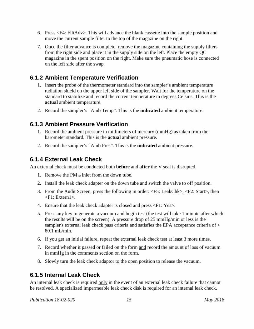
6.1.2 Ambient Temperature Verification 1. Insert the probe of the thermometer standard into the sampler’s ambient temperature
radiation shield on the upper left side of the sampler. Wait for the temperature on the standard to stabilize and record the current temperature in degrees Celsius. This is the actual ambient temperature.
2. Record the sampler’s “Amb Temp”. This is the indicated ambient temperature.
6.1.3 Ambient Pressure Verification 1. Record the ambient pressure in millimeters of mercury (mmHg) as taken from the
barometer standard. This is the actual ambient pressure.
2. Record the sampler’s “Amb Pres”. This is the indicated ambient pressure.
6.1.4 External Leak Check An external check must be conducted both before and after the V seal is disrupted.
1. Remove the PM10 inlet from the down tube.
2. Install the leak check adapter on the down tube and switch the valve to off position.
3. From the Audit Screen, press the following in order: <F5: LeakChk>, <F2: Start>, then <F1: Extern1>.
4. Ensure that the leak check adapter is closed and press <F1: Yes>.
5. Press any key to generate a vacuum and begin test (the test will take 1 minute after which the results will be on the screen). A pressure drop of 25 mmHg/min or less is the sampler's external leak check pass criteria and satisfies the EPA acceptance criteria of < 80.1 mL/min.
6. If you get an initial failure, repeat the external leak check test at least 3 more times.
7. Record whether it passed or failed on the form and record the amount of loss of vacuum in mmHg in the comments section on the form.
8. Slowly turn the leak check adaptor to the open position to release the vacuum.
6.1.5 Internal Leak Check An internal leak check is required only in the event of an external leak check failure that cannot be resolved. A specialized impermeable leak check disk is required for an internal leak check.

Publication 18-02-020 16 May 2018
Contact the Calibration & Repair Lab to acquire the leak check disk if you do not have one. A leak check adapter is not needed for an internal leak check.
1. Insert a leak check cassette that has a leak check disk in place of the usual filter. Advance the leak check cassette to the sampling chamber.
2. From the Audit Screen, press the following in order <F5: LeakChk>, <F2: Start>, then <F2: Intern1>.
3. Press any key to generate a vacuum and begin test (the test will take 1 minute after which the results will be on the screen). A pressure drop of 140 mmHg/min or less is the sampler's internal leak check pass criteria and satisfies the EPA acceptance criteria of < 80.1 mL/min. Record internal leak result in comments of the QC check form.
4. If a failure message has displayed, clean the cassette and leak check disk carefully. Examine the cassette and disk for any external nicks or scratches. Discard any damaged cassette or disks, and re-run the test with a clean, undamaged cassette and leak check disk.
5. Record whether it passed or failed on the form and record the amount of loss of vacuum in mmHg in the comments section on the form.
6.1.6 Flow Rate Verification Use a Gilibrator, Alicat or other certified, NIST-traceable flow standard to perform the flow rate verification as follows.
1. With the leak check adapter installed on the down tube, use nylon tubing to connect it to your flow transfer standard.
2. Turn on the pump by pressing <F1: Pump>, and open the valve by pressing <F2: Valve>.
3. Wait 5 minutes for the sampler’s “Cur Flow” to stabilize (it should be about 16.7 L/min).
4. Record the flow in L/min (at ambient temperature and pressure) as taken from the transfer standard. This is the actual flow.
5. Record the sampler’s “Cur Flow” in L/min. This is the indicated flow.
6. Turn off the pump by pressing <F1: Pump>, and close the valve by pressing <F2: Valve>.
6.1.7 PM10 Head Inspection 1. Pull up on the PM10 inlet to remove it from the down tube.
2. Unscrew the bottom portion of the inlet from the cap and inspect it for cleanliness.
3. Inspect the O-ring that seals the top and bottom of the inlet head. Note if it’s broken.
4. Note whether the impact plate is clean on the QC check form.
5. Carefully put the PM10 head back together and set it on the ground such that it’s out of the way and possible contaminants (rain, dust and insects) do not enter the collector assembly.

Publication 18-02-020 17 May 2018
6.1.8 VSCC™ Inspection (PM2.5 only) Remove the VSCC™ from the upper part of the sampler enclosure and inspect the transfer tube and emptying cup as shown in Figure 11. Inspect the O-rings for tear and/or damage.
6.1.9 Filter Temperature Verification *Important: An external check must be conducted before and after disrupting the VSCC™ and V seals as an “as-found” and “as-left” condition, respectively.
1. Open the top compartment of the sampler and remove the VSCC™ (PM2.5) or the downtube adapter (PM10).
1. Insert the thermometer standard probe into the tube from which the VSCC™ or downtube adapter was removed. This is where the sampler’s filter temperature probe is located.
2. Allow 3 minutes for your standard’s temperature to stabilize.
3. Record the filter temperature in degrees Celsius as taken from the thermometer standard. This is the actual filter temperature.
4. Record the sampler’s “Filt Temp”. This is the indicated filter temperature.
5. Reinstall the VSCC™ (PM2.5) or downtube adapter (PM10) and completely close and seal the top compartment of the sampler.
6.1.10 Finishing the Quality Control Check 1. Perform a final “as-left” external leak check and document the results on the QC check
form. If the external leak check fails, refer to the instructions in Section 6.1.4.
2. Remove the leak check adapter from the down tube.
3. Reinstall the PM10 head on the down tube.
4. Press <F4: FiltAdv> to advance the current sample filter back into sampling position and move the audit cassette back into the QC magazine on the right side of the sampler.
5. Remove the QC magazine from the storage side (right side) and cap it.
6. Uncap the spent magazine and reinstall it on the storage side.
7. Visually verify that you’ve put the sampler back together correctly and that the magazines are back in place as you found them at the beginning of the QC check.
8. Press <Run/Stop> to put the sampler back into the mode in which you found it (i.e., WAIT or SAMP). Verify this by looking at the upper right part of the screen.
9. Record the QC check stop time on the electronic QC form.
10. Calculations (the electronic Excel QC sheet will perform these for you). Perform all calculations before leaving the site. The electronic QC form will calculate these values automatically.
Flow Percent Difference = Indicated − Actual Actual × 100 %

Publication 18-02-020 18 May 2018
Design Value Percent Difference = Indicated − 16.67 16.67 × 100 %
11. Make an electronic logbook entry and record your quality control activities and findings.
Calibration Procedure • It is strongly recommend that calibration activities be performed on a day when sampling is
not scheduled, unless interrupting sampling is unavoidable (e.g., daily sampling).
• To calibrate any parameter, the sampler must first be in Stop Mode. From the Stop Mode, you can then access the sampler’s Service Mode where adjustments can be made.
• It is important that the procedures described in this section be performed in the order in which they are described.
6.2.1 Beginning the Calibration 1. Verify that the sampler is in Stop Mode. If not, press <Run/Stop> to place the
sampler in Stop mode.
2. Press <Menu> to display the Master Menu. Scroll to the Service Menu option, press <Enter>, as shown in Figure 7.
3. Press <F1: Audit> to enter Audit Mode. Verify this by looking at the upper right corner of the display screen before proceeding.
4. Insert a filter cassette containing a new 47 mm filter in the top-most position in the supply magazine (left side).
5. Press <F4: FiltAdv> to move the filter into the sampling position.
Figure 7. Master menu (Thermo 2006).

Publication 18-02-020 19 May 2018
To exit Service Mode at any time, select the Exit Service Mode option in Service Menu as shown in Figure 8.
Figure 8. Service menu (Thermo 2006).
6.2.2 Ambient Temperature Calibration 1. Press <Menu> to enter Service Menu. Scroll to the Calibration/Audit option, as shown in
Figure 8, press <F3: SensCal> to access the Sensor Calibration screen.
2. Loosen the two screws on either side of the temperature probe on the ambient temperature assembly and remove the probe from the radiation shield. Band together the reference and sampler probe and immerse them into the same depth in an insulated container of water.
Take measurements about 1 minute apart in three temperature conditions: in an ice slurry, at ambient conditions, and in warm water at approximately 120°F. Allow the reference and sampler probes to equilibrate for at least 5 minutes at each temperature before taking the reading. Use the average ambient measurement in the next step.
3. Press <Edit> then enter the average temperature of the reference standard in °C from Step 2 in the Actual column of the Amb Temp row on the screen and press <Enter>. The sampler automatically adjusts the corresponding offset based upon this input.
4. Perform a single point temperature verification to confirm the calibration.
5. Reinstall the ambient temperature probe in the radiation shield and tighten the two screws on either side of the probe.
6.2.3 Filter Temperature Calibration 1. Press <Menu> to enter the Service Menu. Scroll to the Calibration/Audit option, press
<F4: FiltCal> to enter the Filter Temperature Calibration Screen.
2. Open the top compartment of the sampler and remove the VSCC™ (PM2.5) or downtube (PM10).

Publication 18-02-020 20 May 2018
3. Using a thermometer standard, insert the probe into the tube from which the VSCC™ or downtube was removed and measure the current temperature at the location of the filter temperature probe in the sampler.
4. Press <Edit> and enter the measured filter temperature from the reference standard in °C in the Actual column of the Filt Temp row on the screen and press <Enter>. The sampler automatically adjusts the corresponding offset based upon this input.
5. Perform a single point temperature verification to verify the calibration.
6.2.4 Ambient Pressure Calibration 1. Press <Menu> to enter the Service Menu. Scroll to the Calibration/Audit option. Press
<F3: SensCal> to enter the Sensor Calibration Screen.
2. Record the current ambient pressure in mmHg from the reference standard.
3. Press <Edit> and enter the measured ambient pressure in the Actual column of the Amb Pres row of the Sensor Calibration Screen. Press <Enter>. The sampler automatically adjusts the corresponding offset based upon this input.
6.2.5 Troubleshoot Leak Check A leak check must be performed any time a seal in the sampler is disturbed. A failed leak check cannot be “calibrated” and must be resolved by identifying the leak source. This subsection describes basic procedures to troubleshoot a failed leak check during a calibration or QC check.
1. Follow leak check procedures in Section 6.1.4 and 6.1.5 if needed.
2. If a leak check fail message is displayed on the screen:
• External Insert a new filter cassette containing a new 47 mm filter in the topmost position of the supply magazine. From the Service Menu, go to <F1: Audit> to advance the cassette (<F4: FiltAdv>) into the sample position. Repeat the leak check procedure.
• Internal Clean the cassette and leak check disk carefully. Examine the cassette and disk for any external nicks or scratches. Discard any damaged cassette or disks, and re-run the test with a clean, undamaged cassette and leak check disk.
3. If the leak check fails again, attempt to find the leak and repair. Failure in both external and internal leak checks may indicate a defected bottom V seal or poor hose connection to the pump. A failed external but passed internal may indicate a leak above the filter position, such as the top V seal or inlet assembly.
4. If you can’t locate the source of the leak, contact the Calibration & Repair Lab for assistance.
5. When the leak check is complete and passed, slowly open the valve on the leak check adapter to release the vacuum.

Publication 18-02-020 21 May 2018
6. If performing a flow verification immediately, retain the filter cassette with filter in the sampling position. Otherwise, remove the adapter, reinstall the PM10 head and remove the blank test filter cassette in the sampling position (see Section 6.1.10, Steps 1-7).
6.2.6 Clock Calibration Depending on the mode prior to entering Stop Mode, follow the steps in which they are described below to perform clock adjustment. Bring a blank cassette for this procedure.
From Wait Mode:
1. Press <Run/Stop> and go to Stop Mode.
2. Press <F5: Setup> and then <F5: System> to enter the System Setup screen (Figure 4).
3. Press <Edit> and move the cursor to Curr Time. Adjust time using keypad or <+List> and <-List>.
4. Press <Enter> to save the change. This will take about 15 seconds to post in the system. Press <Esc> to return to the Main screen.
5. To ensure the sample matches the correct filter ID, go to the Filter List screen. Press <F3: FiltSet> and then <F4: FiltLst>.
6. With the cursor on filter #1, click <F4: Insert> to insert a new row. Enter the very next scheduled filter and cassette numbers and press <Enter> to save.
7. Press <Esc> once and then <F1: Times> to display the scheduled run. Curr and #1 should have the same date.
8. Swap the two magazines in position, then place a blank cassette on top of the left magazine.
9. Advance the filter. Press <Menu>, select <Service Mode>, select <F1: Audit>, then <F4: FilterAdv>. This advances the blank cassette to the sample chamber and pushes the actual sample to the magazine on the right.
10. Swap the two magazines again so the supply magazine is now on the left side with the sample previously in the sample chamber at the topmost position.
11. Press <Esc> to Main screen and press <Run/Stop>. Sampler should go back to Wait Mode. The next scheduled run will push out the blank cassette in the sample chamber.
From Done Mode:
1. After all the filters sampled and the sampler is in Done Mode with “No filter” error.
2. Adjust the time following steps 1-4 above. If you are entering the next batch of sample and cassette IDs, follow instructions in Section 5.1.
3. Clear error and hit <Run/Stop> to put it back to Wait Mode.
Instructions courtesy of Scott Honodel (NWRO) and John Wolbert (HQ)

Publication 18-02-020 22 May 2018
6.2.7 Flow Calibration Perform the temperature calibration, pressure calibration and leak check described above before performing the three-point flow calibration procedure.
1. Remove the PM10 head from the down tube and install a leak check adapter with its valve open.
2. Attach a certified flow standard to the leak check adapter.
3. Press <Edit> and enter the desired minimum and maximum calibration flow rates (Min. Flow and Max. Flow). The recommended flows are 15.0 lpm for Min Flow and 18.4 lpm for Max Flow. These values are 10 % below and 10 % above 16.7 lpm, respectively.
4. For Num Points, enter 3 for three calibration points.
5. Press <F5: More> and then <F4: Start> to initiate the flow.
6. Wait for the flow to stabilize, then press <Edit> and enter the measured flow (lpm) from the flow standard in the “Act Flow” field. Move to the next calibration point. Press <Enter> to save.
7. The sampler automatically adjusts the Offset and Span values in the Flow Calibration Screen once the calibration is complete.
8. Perform a single point flow rate verification to confirm the calibration.

Publication 18-02-020 23 May 2018
7. Maintenance This section describes the minimum routine maintenance that must take place to ensure proper instrument operation. Depending on the sampling environment, maintenance may need to be conducted more frequently. All maintenance activities must be documented in the electronic logbook. Table 4 summarizes the required maintenance procedures and frequencies. See Appendix C for the Maintenance Check Sheet that must be kept at the station to help operator keep track of QC check and maintenance frequency. *Important: Operator must perform a final as-left external leak check after maintenance involved disrupting the V seals and document the results in the electronic logbook or QC Check Form. Table 5. Required maintenance activities
Procedure Minimum Required Frequency Section Clean the PM10 head Every 30 days (monthly) 7.1
Inspect the condensation jar Every 5 sampling days; clean as needed 7.1, Step 8.
Clean the VSCC™ (PM2.5 only) Every 30 days 7.2
Inspect the V seals Every 30 days 7.3
Clean interior sample case Every 30 days 7.4
Clean air intake screens Every 180 days (semi-annually) 7.5
Exchange particle trap filters Every 365 days (annually) 7.6
Clean the downtube Every 365 days 7.7
Multi-point temperature verification Every 365 days 6.2.2
Multi-point flow rate verification Every 365 days 6.2.7
Pressure calibration Every 365 days 6.2.4
Replace batteries Every 365 days 7.8

Publication 18-02-020 24 May 2018
Clean the PM10 Head 1. Unscrew the collector assembly from the acceleration assembly as shown in Figure 9.
Acceleration Assembly 2. Remove the four screws on the underside of the lower plate of the assembly and separate
the top plate from the insect screen and assembly body.
3. Clean the plates and insect screen using brushes, lint-free cloth and/or compressed air. The parts may be cleaned with water, but they must be dried thoroughly before reassembly.
4. Reassemble the plates and screen, and secure with screws back on the assembly body.
5. Inspect the O-ring for damage. Replace if necessary. Some aluminum shards may stick on the O-ring from assembly misalignments; clean with brushes or lint-free cloth as needed. Apply a thin grease coating on the O-ring and the aluminum threads of the acceleration assembly using silicone grease.
Collector Assembly 6. Clean the collector plate and walls around the three vent tubes using brushes, lint-free
cloth, and cotton swabs. Likewise, wipe clean the bottom side of the collector assembly.
7. Using cotton swabs, clean the weep hole in the collector plate where the moisture runs out to the moisture trap.
8. Remove the condensation jar and wipe clean the jar and cap. Inspect the brass fitting to ensure tightness and non-blockage. When reinstalling the jar, grease the gasket inside the cap of the jar to ensure a leak-free seal.
9. Inspect the two inlet-to-inlet tube sealing O-rings for damage. Replace if necessary. Apply a thin grease coating on the O-rings to ensure a proper seal.
10. Hand-tighten the acceleration assembly and collector assembly.
Figure 9. PM10 inlet head components (Vaughn 2009).

Publication 18-02-020 25 May 2018
Figure 10. Exploded cross-sectional view of PM10 inlet (EPA 2016).
Clean the VSCC™ (PM2.5 only) 1. Remove the top cap and the emptying cup as shown in Figure 11.
2. Use a damp lint-free wipe to remove visible dirt and debris, paying close attention to the emptying cup and the cone inside the top cap.
3. Inspect the O-rings for damage and adequate lubrication. Replace O-rings and apply silicone grease if necessary.
4. Reinstall the VSCC™ on the inlet.

Publication 18-02-020 26 May 2018
Figure 11. Exploded view of VSCC™ components and downtube adapter.
Inspect the V Seals 1. Ensure the instrument is in Stop Mode.
2. Open the top cover of the sampler. Removing the PM10 inlet is optional when opening the cover.
3. Remove the VSCC™ (PM2.5) or downtube assembly (PM10) inside the sampler enclosure.
4. Locate the downtube mount V seal that is at the bottom of the enclosure lid as shown in Figure 12. Examine seal for drying and/or cracking. Grease the seal with a light coating of silicone grease or replace as necessary.
5. Remove the electronics cover from the top enclosure. Depending on the sampler models, you may have to remove the exit cylinder cover first before removing the electronics cover.
6. Remove the front cover of the electronics compartment by removing the four screws.
7. Enter Service Mode.
8. Scroll the pointer to the System Maintenance Routines option, select <F2: LeakChk> and then <F3: ClnSeal> to initiate the seal cleaning procedure.

Publication 18-02-020 27 May 2018
9. Following the instructions on the screen, remove the mounting plate where the top head is attached and the cassette in the sampling position from the enclosure. Press <F4: Done> when complete. The filter exchange assembly will push up so the bottom V seal is more accessible for cleaning.
10. The top and bottom V seals are now exposed. The top seal is located at the bottom of the top head. Examine both seals for drying and/or cracking. Grease the seals with a light coating of silicone grease or replace as necessary.
11. When cleaning is done, press <F4: Done>, then follow the instructions to re-install the components. Press <F4: Done> again when complete. The assembly will push back up to create the seal.
12. Replace all electronics covers and the VSCC™. Close the top cover.
13. Perform an external leak check following Sections 6.1.4.
14. Resume normal operation.
Figure 12. Location of downtube mount V seal.
Clean Interior Sample Case At a minimum of every 30 days, wipe down the interior of the sampler to remove bugs, dirt, and/or water deposits that may have collected inside the enclosure. This may be required more frequently during summer months. Examine the tubing fitting to ensure proper seal and tightness. Inspect the cooling air intake filter during the summer months and clean as necessary.

Publication 18-02-020 28 May 2018
Clean Air Intake Screens The two screens, one in the filter compartment and one in the pump compartment, should be cleaned at a minimum of every 6 months, and more frequently in highly polluted areas.
1. Locate the two air-intake fans. Each of these has an associated air intake screen.
2. Snap off the covers enclosing the air intake screens.
3. Take out the screens and clean them with a brush or wash them with a mild soap solution and water (must be dried thoroughly before reassembly).
4. Reinstall the screens in their holders and remount the covers.
Exchange Particle Trap Filters
The particle trap filters are located behind the filter exchange assembly. Perform the procedure below to inspect and exchange the particle trap filters once a year.
1. Turn off the sampler.
2. Locate the bowl-style filter behind the filter exchange assembly. Remove the filter bowl by unscrewing it from the filter manifold.
3. Carefully remove the filter stand by unscrewing it from the filter. The O-ring usually remains in the filter manifold.
4. Remove the gasket and top disk from the filter stand. The gasket might sometimes remain inside the filter manifold.
5. Inspect the filter element for cleanliness. To replace, remove the filter element from the filter stand and install a new element.
6. Install the top disk and gasket if necessary into the filter stand.
7. Install the filter stand into the filter manifold. Install the O-ring into the filter manifold, if necessary.
8. Install the filter bowl into the filter manifold.
9. Turn on the sampler and perform a system (external) leak check.
Clean the Downtube Inspect the outer and inner surfaces of the tip (closest to the sampler inlet) of the downtube. Remove any particulate deposits using isopropyl rubbing alcohol or water and lint-free wipes or brushes. Dry the downtube completely before reinstallation.

Publication 18-02-020 29 May 2018
Replace Batteries The three alkaline AA batteries in the electronics provide backup power for internal data storage and the clock/calendar. The expected lifetime of the batteries in the instrument is 1 year. Batteries must be tested annually and be replaced as needed. Operators should always wear appropriate anti-static gloves when working with the system electronics.
1. Remove the three screws securing the Pump Compartment Cover and the cover.
2. Open the electronics compartment of the sampling unit and locate the batteries.
3. Check whether the batteries need replacing by measuring the voltage across the test point labeled “BATT” (red) on the interface board and the ground test point labeled “188_PGND”. If the measured voltage is less than 4.2 VDC, the batteries need to be replaced. Skip to Step 6 if the voltage is acceptable.
4. Remove the clip that holds batteries in their mounting and pull the old batteries out and replace them with new ones, noting the proper polarity. Perform this exchange within an elapsed time of 5 minutes to avoid the loss of data stored in the battery-backed RAM.
5. Reinstall the clips that hold the batteries in position. Test for a voltage of 4.2 VDC as in Step 3.
6. Close the electronics compartment of the sampling unit.

Publication 18-02-020 30 May 2018
8. Laboratory Activities The Manchester Environmental Laboratory’s (MEL) PM2.5/PM10 gravimetric laboratory processes all Washington Network PM2.5 and PM10 samples from Sequential Samplers operated within the Washington Network. This work is performed in accordance with all requirements described in:
• 40 CFR Part 50, Appendix J and L, • EPA Quality Assurance Handbook for Air Pollution Measurement Systems, Volume II, • EPA Quality Assurance Guidance Document 2.12, and • EPA Technical Note (Oct 2015) on Holding Time Requirement for PM2.5 Filter Samples
The personnel responsible for the laboratory activities will perform tasks including, but not limited to:
• Ship and receive the samples to and from the operators • Verify the integrity of the samples upon receipt, including visual check of the filter
samples and storage/cooler conditions • Perform gravimetric analysis, including pre-weighing and post-weighing • Record any noticeable aspects of the filter sample and/or weighing conditions • Generate summary reports based on information gathered from the Sequential Sampler
Data Run Sheet and gravimetric analysis A detailed description of the laboratory activities can be found in the MEL’s PM2.5/PM10 Gravimetric Laboratory Standard Operating Procedure. Contact MEL for a copy if needed. After the gravimetric analysis, MEL sends PM10 samples to Eastern Research Group Inc. (ERG) for lead (Pb) analysis for NAAQS compliance purposes, as well as other metals analysis in accordance with the National Air Toxics Trends Stations (NATTS) Network requirements.
Publication 18-02-020 31 May 2018
9. Data Validation and Reporting
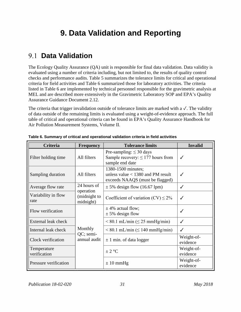
Data Validation The Ecology Quality Assurance (QA) unit is responsible for final data validation. Data validity is evaluated using a number of criteria including, but not limited to, the results of quality control checks and performance audits. Table 5 summarizes the tolerance limits for critical and operational criteria for field activities and Table 6 summarized those for laboratory activities. The criteria listed in Table 6 are implemented by technical personnel responsible for the gravimetric analysis at MEL and are described more extensively in the Gravimetric Laboratory SOP and EPA’s Quality Assurance Guidance Document 2.12.
The criteria that trigger invalidation outside of tolerance limits are marked with a ✓. The validity of data outside of the remaining limits is evaluated using a weight-of-evidence approach. The full table of critical and operational criteria can be found in EPA’s Quality Assurance Handbook for Air Pollution Measurement Systems, Volume II. Table 6. Summary of critical and operational validation criteria in field activities
Criteria Frequency Tolerance limits Invalid
Filter holding time All filters Pre-sampling: ≤ 30 days Sample recovery: ≤ 177 hours from sample end date
✓
Sampling duration All filters 1380-1500 minutes; unless value < 1380 and PM result exceeds NAAQS (must be flagged)
✓
Average flow rate 24 hours of operation (midnight to midnight)
± 5% design flow (16.67 lpm) ✓
Variability in flow rate Coefficient of variation (CV) ≤ 2% ✓
Flow verification
Monthly QC; semi-annual audit
± 4% actual flow; ± 5% design flow ✓
External leak check < 80.1 mL/min (≤ 25 mmHg/min) ✓
Internal leak check < 80.1 mL/min (≤ 140 mmHg/min) ✓
Clock verification ± 1 min. of data logger Weight-of-evidence
Temperature verification ± 2 °C Weight-of-
evidence
Pressure verification ± 10 mmHg Weight-of-evidence

Publication 18-02-020 32 May 2018
Table 7. Summary of critical and operational validation criteria in lab activities
Criteria Frequency Tolerance limits Invalid
Filter temperatures
All filters
< 25 °C from sample recovery to conditioning ✓
Filter holding time from sample end date to post-conditioning and weighing
Tmax: maximum temperature recorded in the cooler and must be < 25 °C Tavg: average temperature during the 24-hr sampling period • ≤ 30 days if Tmax ≤ Tavg • ≤ 10 days if Tmax > Tavg
✓
Conditioning 24 hours minimum ✓
Temperature 24-hr mean within 20-23 °C and ≤ ±2 °C over 24 hours ✓
Humidity (RH) 24-hr mean within 30-40 %, or within ± 5% sampling RH and ≥ 20 % RH ✓
Exposure lot blanks 3 filters/lot ± 15.1 µg change between weighings Weight-of-evidence
Data Reporting The following final PM analysis reports are sent electronically from MEL:
• A full gravimetric analysis report listing sample information, analysis results and flags if data is deemed invalid by MEL,
• A summary letter to the QA Coordinator, and • Formatted re-engineered AIRS files containing final mass concentrations to Ecology’s
QA and IT units. The IT staff loads the files into the Envista Air Resources Manager (EnvistaARM) software to facilitate data review and validation completed by the QA personnel.
Following final data validation, the Air Quality System (AQS) Coordinator electronically submits all validated data to EPA’s AQS. Additionally, MEL sends quarterly cooler and control chart of the laboratory to field operators and Ecology’s QA personnel to inform the quality control of the filter samples and laboratory condition.

Publication 18-02-020 33 May 2018
10. References 40 C.F.R. Part 50 Appendix J. Reference Method for the Determination of Particulate Matter as PM10 in the Atmosphere. 2016. 40 C.F.R. Part 50 Appendix L. Reference Method for the Determination of Fine Particulate Matter as PM2.5 in the Atmosphere. 2016. 40 C.F.R. Part 58 Appendix A. Quality Assurance Requirements for Monitors used in Evaluations of National Ambient Air Quality Standards. 2016. 40 C.F.R. Part 58 Appendix D. Network Design Criteria for Ambient Air Quality Monitoring. 2016. 40 C.F.R. Part 58 Appendix E. Probe and Monitoring Path Siting Criteria for Ambient Air Quality Monitoring. 2013. BGI, Inc. Very Sharp Cut Cyclone (VSCC) Instructions for Use and Maintenance. Version 1.3, Waltham, MA: BGI, Inc., 2013. Thermo Electron Corporation. Partisol-Plus 2025 Sequential Air Sampler Operating Manual. East Greenbush, NY, 2006. Thermo Fisher Scientific. N.d. “Partisol™ Plus 2025 Sequential Ambient Particulate Sampler.” Partisol™ Plus 2025 Sequential Ambient Particulate Sampler. Web. Accessed 3 Jan 2018. Thermo Fisher Scientific. Thermo Scientific Partisol-Plus 2025i/2025i-D Dichotomous Sequential Air Sampler: Operations Manual. Franklin, MA, 2015. U.S. EPA. Office of Air Quality Planning and Standards. List of Designated Reference and Equivalent Methods, issued December 15, 2017. U.S. EPA. Office of Air Quality Planning and Standards. Quality Assurance Document 2.12: Monitoring PM2.5 in Ambient Air Using Designated Reference or Class I Equivalent Methods. EPA-454/B-16-001, Research Triangle Park, 2016. U.S. EPA. Office of Air Quality Planning and Standards. Quality Assurance Handbook for Air Pollution Measurement Systems Volume II: Ambient Air Quality Monitoring Program. EPA-454/B-13-003, Research Triangle Park, 2013. Vaughn, David L. Standard Operating Procedure for the Continuous Measurement of Particulate Matter: Met One BAM-1020 PM2.5 Federal Equivalent Method EQPM-0308-170, Petaluma: Sonoma Technology, 2009.

Publication 18-02-020 34 May 2018
Appendix A: Sequential Sampler Run Data Sheet

Publication 18-02-020 35 May 2018
Appendix B: PM2.5/PM10 QC Check Form

Publication 18-02-020 36 May 2018
Appendix C: Maintenance Check Sheet
Parameter Frequency Initial and date boxes after each check is completed Acceptance
Criteria Jan Feb Mar Apr May Jun Jul Aug Sep Oct Nov Dec
One-Point Flow Rate Verification
1/ every 4 weeks
± 4 % of the Transfer Standard
Multi-Point Flow Rate Verification
Annual or if One-Point Failure
± 4 % of the Transfer Standard
Flow Rate Calibration If Multi-Point Failure
± 4 % of the Transfer Standard
One-Point Temperature Verification
1/ every 4 weeks
± 2 oC of Standard
Multi-Point Temperature Verification Annual
± 2 oC of Standard
Temperature Calibration If Multi-Point Failure
± 2 oC of Standard
Pressure Verification 1/ every 4 weeks
± 10 mmHg
Pressure Calibration Annual ± 10 mmHg
Clock/timer Verification 1/ every 4 weeks
± 1 minute
External Leak Check 1/ every 4 weeks
≤ 25 mmHg/min
Internal Leak Check If External Leak Failure
≤ 140 mmHg/min

Publication 18-02-020 37 May 2018
Parameter Frequency Initial and date boxes after each check is completed Acceptance
Criteria Jan Feb Mar Apr May Jun Jul Aug Sep Oct Nov Dec
Inspect and Clean PM10 inlet
1/ every 4 weeks
--
Inspect and Clean VSCC™ (PM2.5 only)
1/ every 4 weeks
--
Inspect the V Seals 1/ every 4 weeks
--
Clean Interior of Sample Case
1/ every 4 weeks
--
Clean Air Intake Screens 1 / every 6 months
--
Exchange Particle Trap Filters Annual
--
Water Collector Bottle Inspection
Every 5 sampling events
--