Embed Size (px)
Citation preview

PM IDD9000 Flame Amplifier Publication 372001-02 Rev K

PM IDD9000 Flame Amplifier 372001-02 Rev K
i
INTRODUCTION This manual contains information for the PM IDD9000 Flame Amplifier from Forney Corporation, 16479 North Dallas Parkway, Suite 600 Addison, TX 75001. All personnel should become thoroughly familiar with the contents of this manual before attempting to install, operate or maintain the PM IDD9000 Flame Amplifier system. Because it is virtually impossible to cover every situation that might occur during operation and maintenance of the equipment described in this publication, personnel are expected to use good engineering judgment when confronted with situations that are not specifically mentioned herein. PROPRIETARY NOTICE The contents of this publication are proprietary data of Forney Corporation. Reproduction or use of any part of the publication for purposes other than the support of the equipment for which it is published is permissible only if expressly authorized in writing by Forney. Revisions
Revision Date Comments A 02/2009 Initial Release B 11/2010 C 06/2011 Correct Time-out references for tuning D 07/2011 Add Table 2-13 E 10/2011 Remove Flame By-pass mode – Add TES F 03/2012 Blind Input – J8 section 2.6.1, add single channel model, correct
Alarm relay function & wiring G 09/2013 Add Section 2.5.2 Wiring for one IDD head to both channels H 04/2014 Dual channel amplifiers synchronization J 02/2015 Update Grounding sections and wiring diagrams K 01/2017 Add certificate information and general updates

PM IDD9000 Flame Amplifier 372001-02 Rev K
ii
TABLE OF CONTENTS
Section 1 General Description ..................................................................................... 1
1.1 Specifications ................................................................................................................................... 3
Section 2 Installation .................................................................................................... 4
2.1 Recommended Test/Tuning Equipment and Instructions ................................................................ 4 2.2 Mounting Considerations ................................................................................................................. 4 2.3 Electrical Connections ...................................................................................................................... 5
2.3.1 Amplifier Upgrade Wiring Tables ........................................................................................ 8 2.4 LED Status Displays ...................................................................................................................... 16 2.5 Flame Detector Connections ......................................................................................................... 16
2.5.1 Connecting IDD Detector Heads ....................................................................................... 17 2.5.3 Connecting One IDD Detector Head to Both IDD9000 Channels .................................... 18 2.5.4 Connecting UV-4 Detector Head ...................................................................................... 19 2.5.5 Connecting an IDD and a UV-4 ........................................................................................ 20
2.7 Hardware Control Inputs ................................................................................................................ 21 2.7.1 Blind Input – J8 ................................................................................................................. 21 2.7.2 Sense B Input – J8 ............................................................................................................ 21 2.7.3 Operating Profile Select Inputs – J7 ................................................................................. 21
2.8 Operating Modes ............................................................................................................................ 23 2.9 Configuring the Termiflex/SmartDisplay® Terminal with 25 Pin Connector ................................... 24
Section 3 Amplifier Tuning ......................................................................................... 26
3.1 Mode .............................................................................................................................................. 26 3.1.1 IDD Channel Tuning.......................................................................................................... 26 3.1.2 UV-4 Channel Tuning ....................................................................................................... 30
3.2 Flame Failure Response Time Delay for Modes 1 and 2 .............................................................. 31 3.3 Self-Check Cycle Time for Modes 1 and 2 .................................................................................... 31 3.4 Saving Configuration ...................................................................................................................... 32 3.5 Functions Unavailable While Tuning .............................................................................................. 33 3.6 Analog Outputs .............................................................................................................................. 33 3.7 Amplifier Shutdown/Failure ............................................................................................................ 33
Section 4 Maintenance ................................................................................................ 34
4.1 Tuning ............................................................................................................................................ 34 4.2 Troubleshooting ............................................................................................................................. 34 4.3 Storage and Handling Requirements ............................................................................................. 34

PM IDD9000 Flame Amplifier 372001-02 Rev K
iii
List of Figures Figure 1-1 IDD9000 Block Diagram ............................................................................................. 2
Figure 2-1 PM IDD9000 External Connectors .............................................................................. 5
Figure 2-2 Grounding PM IDD9000 ............................................................................................ 15
Figure 2-3 IDD Detector Head Wiring ......................................................................................... 17
Figure 2-4 Wiring one IDD Detector Head to both IDD9000 Channels ....................................... 18
Figure 2-5 UV-4 Detector Head Wiring ....................................................................................... 19
Figure 2-6 IDD and UV-4 Detector Head Wiring ......................................................................... 20
Figure 3-1 Incorrect Gain Setting ................................................................................................ 27
Figure 3-2 Correct Gain Setting .................................................................................................. 27
List of Tables
Table 2-1 Tuning Equipment ......................................................................................................... 4
Table 2-2 PM IDD9000 Pin-out Summary ................................................................................... 6
Table 2-3 IDD-IIIA to IDD 9000 .................................................................................................... 8
Table 2-4 PM DR6101E to IDD9000 Channel 1 for UV-4 Applications ...................................... 11
Table 2-5 PM DR6101E to PM IDD9000 Channel 1 for IDD Applications ................................. 12
Table 2-6 PM-DR6101E to IDD9000 Channel 2 for UV-4 Applications ...................................... 13
Table 2-7 PM DR6101E to IDD9000 Channel 2 for IDD Applications ........................................ 14
Table 2-8 PM IDD9000 LED Indicators ....................................................................................... 16
Table 2-9 Control Inputs and Flame Detectors (bottom left side panel)...................................... 16
Table 2-10 Profile Select Input Encoding .................................................................................... 22
Table 2-11 Operating Profiles ..................................................................................................... 23
Table 2-12 Termiflex/SmartDisplay® Configuration Settings for IDD 9000 Programming (Factory Default for Termiflex with 9-pin Adapter) ............................................................................. 24
Table 3-1 Keypad Commands ................................................................................................... 26
Table 6-1 Replacement Parts .................................................................................................... 35

PM IDD9000 Flame Amplifier 372001-02 Rev K
1
Section 1 General Description The Forney PM IDD9000 amplifier assembly is a panel-mounted flame detector amplifier, available as single or dual-channel. It is a stand-alone intelligent controller composed of two or three printed circuit board (PCB) assemblies depending on model, contained in a covered chassis. The dual channel IDD 9000 is comprised of two independent motherboards and one LED board with interface handshaking. The single channel contains one motherboard and one interface/LED board. All inputs and outputs are completely independent, including separate fused power feeds on each card. A ribbon cable connects each motherboard to the interface/LED board. The LED board has two sets of status LEDs (one set for each channel) and also facilitates synchronization of channels with each other. Each motherboard has two universal power supplies that produce the two output voltages, 15Vdc and 12Vdc. The 15Vdc supply, powers the detector heads directly, including the 50V Bias for the IDD detectors, the 50V Shutter activation voltage drive, 4-20mA and 0-10V. The 12Vdc powers the 4 signal relays and the logic. The amplifier should be located in a controlled environment such as a separate equipment cabinet. Electrical connection with external equipment is accomplished by means of screw terminal lugs on plug-in connectors for easy maintenance. The amplifier provides power control, signal conversion, and processing control for Infrared Dynamic Detectors (IDD) series and UV-4 detectors. The IDD9000 can support any of the following Forney flame detector head combinations:
Dual Channel Single Channel One or two IDD heads One IDD head
One or two UV-4 heads One UV-4 head One IDD head and one UV-4 head
The IDD flame detector head produces an analog data signal whose amplitude and frequency vary with light intensity; the UV-4 flame detector head produces a digital pulse train whose frequency varies with light intensity. Consequently, the amplifier provides different signal-processing circuitry for these two inputs. Signal processing for the UV-4 input merely blocks low amplitude noise and then routes the pulses to the input of a digital counter. In contrast, signal processing for the IDD signal amplifies the input, generates an averaged dc voltage level and converts it into a digital pulse train output. This pulse train then serves as the input to the microprocessor. At regular intervals, the microprocessor reads the value of the pulse counter(s) and compares those values with tuning parameters from memory. When the count value exceeds the corresponding value from memory, the microprocessor sets a flag to indicate flame presence. In addition, the count values provide a direct measure of infrared or ultraviolet light intensity striking the respective sensors. Accordingly, the PCB uses the two count values to generate separate analog output signals that can be used to drive flame intensity meters. A serial communication port for each channel is located on the front of the PM IDD9000. These ports enable communication between the microprocessors on the board and a hand-held Termiflex/ SmartDisplay® via RS422/RS485 communication protocols. Forney also offers a Windows based software package, Terminal Emulator Software (TES), that supports diagnostics and tuning of the flame detection system. If the firmware in the amplifier detects an internal failure, it generates a corresponding error message that can be downloaded to the Termiflex/ SmartDisplay®. Any failure will be continually broadcast until a reset pushbutton is pressed.

PM IDD9000 Flame Amplifier 372001-02 Rev K
2
Upon completion of installation, the user must connect the Termiflex/ SmartDisplay® to the amplifier and revise the tuning parameters suitable to detect the presence and absence of target flame. User-supplied tuning parameters are stored and remain unchanged until overwritten with new tuning parameters.
Figure 1-1 IDD9000 Block Diagram

PM IDD9000 Flame Amplifier 372001-02 Rev K
3
1.1 Specifications Environmental Extremes Temperature: 0° to 60° C (32° to 140° F)
Humidity: 5% to 95% non-condensing
Power Requirements Supply: 120/240 VAC at 50/60 Hz
Logic power: +12 VDC
Analog power: +15 VDC
Operational Characteristics Output relay rating (SPDT): 3 A at 125 VAC, 250 VAC & 30 VDC
3 relays are available for each channel (Lamp, Main Flame & Alarm*).
Dimensions: 7 7/8 x 10½ x 3 7/8 inches (20 x 26.6 x 9.8 cm)
Flame Strength: 4-20 mA or 0-10 VDC
Flame Failure Response Time (FFRT): 1.0, 2.0, 3.0 or 3.8 seconds
Flame Pickup Time: less than 2 seconds
Nonvolatile RAM: 8 complete operating profiles
Compatible Flame Detector Heads: IDD-II Filtered IR Detector (700nm – 3300nm) IDD-IIL Low Frequency IR Detector (700nm – 3300nm) IDD-IIU Unfiltered IR Detector (400nm – 3300nm) IDD-Ultra UV Detector (200nm – 425nm) UV-4 UV Detector (190nm – 260nm)
* Alarm Relay is energized under ‘No Alarm’ condition.
1.2 Certifications • FM Approved • CE
Compliant standards: FM 7610 -1997 Combustion Safeguards and Flame Sensing Systems EN 298 - 2012 Automatic burner control systems for burners and appliances burning gaseous or liquid fuels * EN61000-4-2 Ed. 2.0 ; 2008 Testing and measurement techniques - Electrostatic discharge immunity test
EN61000-4-3 Ed. 3.2 ; 2010 Testing and measurement techniques. Radiated, radio-frequency, electromagnetic field
immunity test EN61000-4-4 Ed. 2.0 ; 2010 Testing and measurement techniques - Electrical fast transient/burst immunity test EN61000-4-5 ; 2005 Testing and measurement techniques - Surge immunity test EN61000-4-6 Ed. 3.0 ; 2009 Testing and measurement techniques - Immunity to conducted disturbances, induced by radio-
frequency fields 2014/34/EU EU Directives * Complies to performance specification requirements of flame detector with EMC/Electrical assessment criteria II in EN-298; 20122 - FFRT must be set to 1 sec to comply with EN-298;2012
PM IDD9000 Flame Amplifier 372001-02 Rev K
4
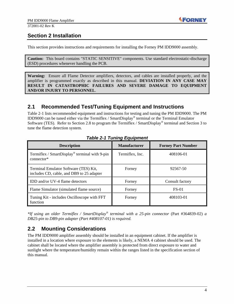
Section 2 Installation
This section provides instructions and requirements for installing the Forney PM IDD9000 assembly. Caution: This board contains "STATIC SENSITIVE" components. Use standard electrostatic-discharge (ESD) procedures whenever handling the PCB. Warning: Ensure all Flame Detector amplifiers, detectors, and cables are installed properly, and the amplifier is programmed exactly as described in this manual. DEVIATION IN ANY CASE MAY RESULT IN CATASTROPHIC FAILURES AND SEVERE DAMAGE TO EQUIPMENT AND/OR INJURY TO PERSONNEL.
2.1 Recommended Test/Tuning Equipment and Instructions Table 2-1 lists recommended equipment and instructions for testing and tuning the PM IDD9000. The PM IDD9000 can be tuned either via the Termiflex / SmartDisplay® terminal or the Terminal Emulator Software (TES). Refer to Section 2.8 to program the Termiflex / SmartDisplay® terminal and Section 3 to tune the flame detection system.
Table 2-1 Tuning Equipment Description Manufacturer Forney Part Number
Termiflex / SmartDisplay® terminal with 9-pin connector*
Termiflex, Inc. 408106-01
Terminal Emulator Software (TES) Kit, includes CD, cable, and DB9 to 25 adapter
Forney 92567-50
IDD and/or UV-4 flame detectors Forney Consult factory
Flame Simulator (simulated flame source) Forney FS-01
Tuning Kit - includes Oscilloscope with FFT function
Forney 408103-01
*If using an older Termiflex / SmartDisplay® terminal with a 25-pin connector (Part #364839-02) a DB25-pin to DB9-pin adapter (Part #408107-01) is required.
2.2 Mounting Considerations The PM IDD9000 amplifier assembly should be installed in an equipment cabinet. If the amplifier is installed in a location where exposure to the elements is likely, a NEMA 4 cabinet should be used. The cabinet shall be located where the amplifier assembly is protected from direct exposure to water and sunlight where the temperature/humidity remain within the ranges listed in the specification section of this manual.
PM IDD9000 Flame Amplifier 372001-02 Rev K
5
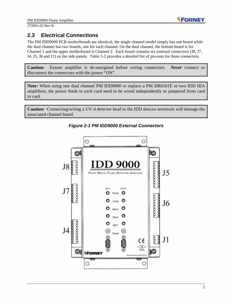
2.3 Electrical Connections The PM IDD9000 PCB motherboards are identical; the single channel model simply has one board while the dual channel has two boards, one for each channel. On the dual channel, the bottom board is for Channel 1 and the upper motherboard is Channel 2. Each board contains six external connectors (J8, J7, J4, J5, J6 and J1) on the side panels. Table 2-2 provides a detailed list of pin-outs for these connectors. Caution: Ensure amplifier is de-energized before wiring connectors. Never connect or disconnect the connectors with the power “ON”. Note: When using one dual channel PM IDD9000 to replace a PM DR6101E or two IDD IIIA amplifiers, the power feeds to each card need to be wired independently or jumpered from card to card. Caution: Connecting/wiring a UV-4 detector head to the IDD detector terminals will damage the associated channel board.
Figure 2-1 PM IDD9000 External Connectors

PM IDD9000 Flame Amplifier 372001-02 Rev K
6
+ Table 2-2 PM IDD9000 Pin-out Summary
Pin Label / Signal Name Function
J8 - VAC Opto Isolator Inputs Top of Left side panel (External connector Part # 9235311)
1 AC Blind
Hot AC Blind, 100 VAC –240 VAC
2 Neutral Neutral Return
3 Shield Cable Shield / Chassis Ground
4 AC Sense B (PS0)
Hot AC Sense B, 100 VAC –240 VAC
5 Neutral Neutral Return
J7 – Profile Select and Blind Inputs Middle of Left side panel (External connector Part #9235313)
1 Profile Select 2 Binary 4, Add all for 0-7 Profile Select
2 Profile Select 1 Binary 2, Add all for 0-7 Profile Select
3 Profile Select 0 Binary 1, Add all for 0-7 Profile Select
4 Ground Electrical ground return for Dry Relay Contacts for J7 pins 1, 2 and 3
5 Shield Cable Shield / Chassis Ground
6 Blind Blind initiated by Dry Relay Contacts
7 Ground Electrical ground return for Dry Relay Contacts for J7 pin 6
J4 – Control Inputs and Flame Detectors Bottom of Left side panel (External connector Part #9235314)
1
IDD Scanner
15 VDC () +15 VDC IDD detector (F2, 0.125A fuse)
2 Signal IDD flicker signal input
3 50 VDC Bias +50 VDC Bias, 5mA, (F6, 62mA fuse)
4 Ground Electrical ground return for detector
5 Shield Chassis (cable shield)
6
UV-4 Scanner
15 VDC (fused) +15 VDC PPS detector (F3, 0.250A fuse)
7 Signal UV-4 pulse signal input, 0-5VDC
8 Shutter out Shutter power, 50VDC pulse, 15VDC @ 400mA hold
9 Ground Shutter return / Electrical ground return

PM IDD9000 Flame Amplifier 372001-02 Rev K
7
Pin Label / Signal Name Function
J5 – Detector Analog Signal Outputs Top of Right side panel (External connector Part #9235312) 1
UV-4 Scanner
15 VDC (fused) +15 VDC UV-4 4-20mA (F4, 0.125A)
2 4-20 mA Return UV-4 Pulse Signal, 4-20mA return PPS
3 0-10 VDC UV-4 Pulse Signal, 0-10V analog output
4 Ground Electrical Ground return for detector
5 Shield Shield
6
IDD Scanner
15 VDC (fused) +15 VDC IDD 4-20mA (F5, 0.125A)
7 4-20 mA Return IDD flicker signal, 4-20mA return PPS
8 0-10 VDC IDD flicker signal, 0-10V PPS analog output
9 Ground Electrical Ground return for detector
10 Shield Cable Shield / Chassis Ground
J6 – Relay Contact Outputs – shown under no power condition Middle of Right side panel (External connector Part #9235310)
1
Flame*
Normally Open
2 Common
3 Normally Closed
4
Lamp*
Normally Open
5 Common
6 Normally Closed
7
Alarm**
Normally Open
8 Common
9 Normally Closed
J1 – Power Supply Bottom of Right side panel (External connector Part #9235309)
1 120/240 VAC Line voltage input (F1, 2.0 A fuse)
2 Neutral Neutral / Return
3 Chassis Ground Electrical Ground J2 and J3 are internal interface connectors on the motherboard. J2 is a 26-pin connector on the rear edge of the PCB. This connector mates with a heavy-duty multi-conductor ribbon cable that serves as the communication for the board. J3 is a 6-pin connector for the programming. * Relay energizes and normally open contacts close on stated condition. ** Alarm relay energizes and normally open contact closes when power is applied to IDD9000, if no
alarm condition exists. When alarm condition exists, the alarm relay de-energizes.

PM IDD9000 Flame Amplifier 372001-02 Rev K
8
2.3.1 Amplifier Upgrade Wiring Tables Upgrading from an IDD-IIIA The IDD-IIIA amplifier is a single channel amplifier that only supports and connects to a single IDD type flame detector. Only one channel of the PM IDD9000 is needed to replace one IDD-IIIA amplifier. (If a dual channel PM IDD9000 is used, the bottom board is Channel 1(CH1) and the top board is Channel 2 (CH2). Before removing the IDD-IIIA, label each wire that is connected to the IDD-IIIA with its terminal number. The wires will not reconnect to the same terminal numbers. Disconnect the wires and remove the IDD-IIIA; install the PM IDD9000, which has the same footprint. The PM IDD9000 has 6 External connectors that then connect to the amplifier. Connect wires to the appropriate IDD9000 External connector by using the table and/or diagrams. CAUTION: Connecting/wiring a UV-4 detector head to the IDD detector terminals will damage the associated channel board.
Table 2-3 IDD-IIIA to IDD 9000
IDD-IIIA Pin and Label on Amplifier Cover PM-IDD 9000 Connector / Pin and Label
Left Terminal Block
F 4-20 ma INPUT (Not Used) Not Used
E 4-20 ma OUTPUT J5 Pin 6 15 VDC (fused)
D 4-20 ma COM. J5 Pin 7 4-20 mA Return
C 0-10 VDC J5 Pin 8 0-10 VDC
B SENS B J7 Pin 3* Profile Select 0
SENS B is now Set 1 on the Termiflex.
A Fx4 J7 Pin 2* Profile Select 1
Fx4 is now Set 2 on the Termiflex.
12 Not Used N/A
11 Not Used N/A
10 120 VAC BLIND J8, Pin 1 AC Blind Hot
For AC Blinding you must also jumper J8 pin 2 (AC Blind Neutral) to J1 pin 2 (Neutral).
9 Not Used N/A
8 Not Used N/A
7 DET. GROUND (Black wire) J4 Pin 4 IDD Detector Ground
6 DET. SHIELD J4 Pin 5 Shield

PM IDD9000 Flame Amplifier 372001-02 Rev K
9
IDD-IIIA Pin and Label on Amplifier Cover PM-IDD 9000 Connector / Pin and Label
5 DET +15 VDC (Red wire) J4 Pin 1 IDD Detector 15 VDC (fused)
4 DET +50 VDC (green wire) J4 Pin 3 IDD Detector 50 VDC Bias
3 Not Used N/A
2 DET. SIGNAL (White wire) J4 Pin 2 IDD Detector Signal
1 METER (-) N/A
Right Terminal Block
G Not Used N/A
H SENS B 115 VAC J8 Pin 4 AC Sense B (PS0) Hot
I MAIN FLAME LIGHT N.C. J6 Pin 6 Lamp Normally Closed
J MAIN FLAME 2 N.C. N/A *Note 1
K MAIN FLAME 1 N.C. J6 Pin 3 Flame Normally Closed
L CHECK ALARM N.C. J6 Pin 7 Alarm Normally Open**
13 CHECK ALARM N.O. J6 Pin 9 Alarm Normally Closed **
14 CHECK ALARM COM. J6 Pin 8 Alarm Common**
15 MAIN FLAME 1 COM. J6 Pin 2 Flame Common
16 MAIN FLAME 1 N.O. J6 Pin 1 Flame Normally Open
17 MAIN FLAME 2 COM. N/A *Note 1
18 MAIN FLAME 2 N.O. N/A *Note 1
19 AC INPUT 240 V J1 Pin 1 120/240 VAC
20 AC INPUT 120 V J1 Pin 1 120/240 VAC
21 AC INPUT NEUT J1 Pin 2 Neutral
22 MAIN FLAME LIGHT N.O. J6 Pin 4 Lamp Normally Open
23 MAIN FLAME LIGHT COM J6 Pin 5 Lamp Common
24 METER (+) N/A *Note 2
* If your existing application uses SENS B or Fx4 you must wire as described in table and program Set 1 or 2 with the Termiflex. Dry Relay Contacts connect to ground (J7 pin 4) to activate. *Note 1: If Main Flame 2 on your IDD IIIA was wired as a seriesed safety relay, this is no longer necessary as it is wired internally on the IDD 9000. *Note 2: The IDD9000 does NOT support ±500 micro amp meter. ** Unlike the IDD-IIIA amplifier, ‘ALARM’ Relay on the PM-IDD9000 amplifier is energized on ‘NO ALARM’ condition.

PM IDD9000 Flame Amplifier 372001-02 Rev K
10
Upgrading from a PM DR6101E The PM DR6101E and the dual channel PM IDD9000 amplifiers are both dual channel amplifiers with each channel capable of supporting an IDD series or a UV-4 flame detector head. First determine the type of flame detector to be connected to the channels, either an IDD series or a UV-4 flame detector. Jumpers in the PM-DR6101E select the type of flame detector, and the Termiflex is used to select detector type for the PM IDD9000 channels. The bottom board of the PM IDD9000 is Channel 1 (CH 1) and the top board is Channel 2 (CH 2). Once the type of flame detector has been determined, remove the left and right terminal strips from the PM DR-6101E; remove the PM-DR6101E; install the dual channel PM IDD9000 which has the same footprint. Reconnect the wires one at a time from the PM-DR6101E terminal strips to the PM IDD9000 connectors. The dual channel PM IDD9000 has 6 External connectors per channel (12 total) that then connect to the amplifier. Connect wires to the appropriate IDD9000 External connector by using the following four tables. CAUTION: Connecting/wiring a UV-4 detector head to the IDD detector terminals will damage the associated channel board.

PM IDD9000 Flame Amplifier 372001-02 Rev K
11
Table 2-4 PM DR6101E to IDD9000 Channel 1 for UV-4 Applications
PM DR-6101E Pin and Label on Amplifier Cover
IDD9000 Connection / Pin and Label
Left-side P1-1 SHIELD J4, Pin 5 Shield
P1-3 CH 1 SIG (White wire) J4, Pin 7 UV-4 Detector - Signal
P1-4 POWER (15 VDC) (Red wire) J4, Pin 6 UV-4 Detector - 15 VDC (fused)
P1-5 UV SHTR HI (Green wire) J4, Pin 8 UV-4 Detector - Shutter Out
P1-6 UV SHTR RTN (Black wire) J4, Pin 9 UV-4 Detector - Ground
P1-11 CH 1 SENS B – 115/230V N J8, Pin 5 AC Sense B (PS0) - Neutral
P1-12 CH 1 SENS B – 115/230V H J8, Pin 4 AC Sense B (PS0) - Hot
P1-13 CH 1 BLD – 115/230V N J8, Pin 2 AC Blind - Neutral
P1-14 CH 1 BLD – 115/230V H J8, Pin 1 AC Blind - Hot
Right-side P3-1 GROUND J1, Pin 3 Chassis Ground
P3-2 115/230V IN-H J1, Pin 1 120/240 VAC
P3-3 115/230V IN-N J1, Pin 2 Neutral
P3-4 CH 1 LIGHT MFL – N.C. J6, Pin 6 Lamp - Normally Closed
P3-5 CH 1 LIGHT MFL - COM J6, Pin 5 Lamp - Common
P3-6 CH 1 LIGHT MFL – N.O. J6, Pin 4 Lamp - Normally Open
P3-7 CH 1 FLAME MF – N.C. J6, Pin 3 Flame - Normally Closed
P3-8 CH 1 FLAME MF - COM J6, Pin 2 Flame - Common
P3-9 CH 1 FLAME MF – N.O. J6, Pin 1 Flame - Normally Open
P3-10 CH 1 ALARM ALM – N.C. J6, Pin 7 Alarm - Normally Open*
P3-11 CH 1 ALARM ALM - COM J6, Pin 8 Alarm – Common*
P3-12 CH 1 ALARM ALM – N.O. J6, Pin 9 Alarm - Normally Closed*
P3-26 CH 1/ 0-10VDC OUT - H J5, Pin 3 UV-4 Detector - 0-10 VDC
P3-27 CH 1/ 0-10VDC OUT - L J5, Pin 4 UV-4 Detector - Ground
P3-28 CH 1/ 4-20mA OUT - H J5, Pin 1 UV-4 Detector - 15 VDC (fused)
P3-29 CH 1/ 4-20mA OUT - L J5, Pin 2 UV-4 Detector - 4-20 mA Return
* Unlike the PM DR6101E amplifier, ‘ALARM’ Relay on the PM-IDD9000 amplifier is energized on ‘NO ALARM’ condition.

PM IDD9000 Flame Amplifier 372001-02 Rev K
12
Table 2-5 PM DR6101E to PM IDD9000 Channel 1 for IDD Applications PM DR-6101E Pin and Label on Amplifier Cover
IDD9000 Connection / Pin and Label
Left-side
P1-1 SHIELD J4, Pin 5 Shield
P1-3 CH 1 SIG (White wire) J4, Pin 2 IDD Detector - Signal
P1-4 POWER (15 VDC) (Red wire) J4, Pin 1 IDD Detector - 15 VDC (fused)
P1-7 GOUND Black wire) J4, Pin 4 IDD Detector - Ground
P1-8 IDD BIAS (50 VDC) (Green wire)
J4, Pin 3 IDD Detector - 50 VDC Bias
P1-11 CH 1 SENS B – 115/230V N J8, Pin 5 AC Sense B (PS0) - Neutral
P1-12 CH 1 SENS B – 115/230V H J8, Pin 4 AC Sense B (PS0) - Hot
P1-13 CH 1 BLD – 115/230V N J8, Pin 2 AC Blind - Neutral
P1-14 CH 1 BLD – 115/230V H J8, Pin 1 AC Blind - Hot
Right-side
P3-1 GROUND J1, Pin 3 Chassis Ground
P3-2 115/230V IN-H J1, Pin 1 120/240 VAC
P3-3 115/230V IN-N J1, Pin 2 Neutral
P3-4 CH 1 LIGHT MFL – N.C. J6, Pin 6 Lamp - Normally Closed
P3-5 CH 1 LIGHT MFL - COM J6, Pin 5 Lamp - Common
P3-6 CH 1 LIGHT MFL – N.O. J6, Pin 4 Lamp - Normally Open
P3-7 CH 1 FLAME MF – N.C. J6, Pin 3 Flame - Normally Closed
P3-8 CH 1 FLAME MF - COM J6, Pin 2 Flame - Common
P3-9 CH 1 FLAME MF – N.O. J6, Pin 1 Flame - Normally Open
P3-10 CH 1 ALARM ALM – N.C. J6, Pin 7 Alarm - Normally Open*
P3-11 CH 1 ALARM ALM - COM J6, Pin 8 Alarm - Common*
P3-12 CH 1 ALARM ALM – N.O. J6, Pin 9 Alarm - Normally Closed*
P3-26 CH 1/ 0-10VDC OUT - H J5, Pin8 IDD Detector - 0-10 VDC
P3-27 CH 1/ 0-10VDC OUT - L J5, Pin 9 IDD Detector - Ground
P3-28 CH 1/ 4-20mA OUT - H J5, Pin 6 IDD Detector - 15 VDC (fused)
P3-29 CH 1/ 4-20mA OUT - L J5, Pin 7 IDD Detector - 4-20 mA Return
* Unlike the PM-DR6101E amplifier, ‘ALARM’ Relay on the PM IDD9000 amplifier is energized on ‘NO ALARM’ condition.

PM IDD9000 Flame Amplifier 372001-02 Rev K
13
Table 2-6 PM-DR6101E to IDD9000 Channel 2 for UV-4 Applications
PM-DR6101E Pin and Label on Amplifier Cover
IDD9000 Connection / Pin and Label
Left-side
P1-1 SHIELD J4, Pin 5 Shield
P1-2 CH 2 SIG (White wire) J4, Pin 7 UV-4 Detector - Signal
P1-4 POWER (15 VDC) (Red wire)
J4, Pin 6 UV-4 Detector - 15 VDC (fused)
P1-5 UV SHTR HI (Green wire) J4, Pin 8 UV-4 Detector - Shutter Out
P1-6 UV SHTR RTN (Black wire) J4, Pin 9 UV-4 Detector - Ground
P1-15 CH 2 SENS B – 115/230V N J8, Pin 5 AC Sense B (PS0) - Neutral
P1-16 CH 2 SENS B – 115/230V H J8, Pin 4 AC Sense B (PS0) - Hot
P1-17 CH 2 BLD – 115/230V N J8, Pin 2 AC Blind - Neutral
P1-18 CH 2 BLD – 115/230V H J8, Pin 1 AC Blind - Hot
Right-side
P3-1 GROUND J1, Pin 3 Chassis Ground
P3-2 115/230V IN-H J1, Pin 1 120/240 VAC
P3-3 115/230V IN-N J1, Pin 2 Neutral
P3-13 CH 2 LIGHT MFL – N.C. J6, Pin 6 Lamp - Normally Closed
P3-14 CH 2 LIGHT MFL - COM J6, Pin 5 Lamp - Common
P3-15 CH 2 LIGHT MFL – N.O. J6, Pin 4 Lamp - Normally Open
P3-16 CH 2 FLAME MF – N.C. J6, Pin 3 Flame - Normally Closed
P3-17 CH 2 FLAME MF - COM J6, Pin 2 Flame - Common
P3-18 CH 2 FLAME MF – N.O. J6, Pin 1 Flame - Normally Open
P3-19 CH 2 ALARM ALM – N.C. J6, Pin 7 Alarm - Normally Open*
P3-20 CH 2 ALARM ALM - COM J6, Pin 8 Alarm - Common*
P3-21 CH 2 ALARM ALM – N.O. J6, Pin 9 Alarm - Normally Closed*
P3-22 CH 2/ 0-10VDC OUT - H J5, Pin 3 UV-4 Detector - 0-10 VDC
P3-23 CH 2/ 0-10VDC OUT - L J5, Pin 4 UV-4 Detector - Ground
P3-24 CH 2/ 4-20mA OUT - H J5, Pin 1 UV-4 Detector - 15 VDC (fused)
P3-25 CH 2/ 4-20mA OUT - L J5, Pin 2 UV-4 Detector - 4-20 mA Return * Unlike the PM DR6101E amplifier, ‘ALARM’ Relay on the PM-IDD9000 amplifier is energized on ‘NO ALARM’ condition.

PM IDD9000 Flame Amplifier 372001-02 Rev K
14
Table 2-7 PM DR6101E to IDD9000 Channel 2 for IDD Applications
PM DR-6101E Pin and Label on Amplifier Cover
IDD9000 Connection / Pin and Label
Left-side
P1-1 SHIELD J4, Pin 5 Shield
P1-2 CH 2 SIG (White wire) J4, Pin 2 IDD Detector - Signal
P1-4 POWER (15 VDC) (Red wire) J4, Pin 1 IDD Detector - 15 VDC (fused)
P1-7 GOUND Black wire) J4, Pin 4 IDD Detector - Ground
P1-8 IDD BIAS (50 VDC) (Green wire)
J4, Pin 3 IDD Detector - 50 VDC Bias
P1-15 CH 2 SENS B – 115/230V N J8, Pin 5 AC Sense B (PS0) - Neutral
P1-16 CH 2 SENS B – 115/230V H J8, Pin 4 AC Sense B (PS0) - Hot
P1-17 CH 2 BLD – 115/230V N J8, Pin 2 AC Blind - Neutral
P1-18 CH 2 BLD – 115/230V H J8, Pin 1 AC Blind - Hot
Right-side
P3-1 GROUND J1, Pin 3 Chassis Ground
P3-2 115/230V IN-H J1, Pin 1 120/240 VAC
P3-3 115/230V IN-N J1, Pin 2 Neutral
P3-13 CH 2 LIGHT MFL – N.C. J6, Pin 6 Lamp - Normally Closed
P3-14 CH 2 LIGHT MFL - COM J6, Pin 5 Lamp - Common
P3-15 CH 2 LIGHT MFL – N.O. J6, Pin 4 Lamp - Normally Open
P3-16 CH 2 FLAME MF – N.C. J6, Pin 3 Flame - Normally Closed
P3-17 CH 2 FLAME MF - COM J6, Pin 2 Flame - Common
P3-18 CH 2 FLAME MF – N.O. J6, Pin 1 Flame - Normally Open
P3-19 CH 2 ALARM ALM – N.C. J6, Pin 7 Alarm - Normally Open*
P3-20 CH 2 ALARM ALM - COM J6, Pin 8 Alarm - Common*
P3-21 CH 2 ALARM ALM – N.O. J6, Pin 9 Alarm - Normally Closed*
P3-22 CH 2/ 0-10VDC OUT - H J5, Pin 8 IDD Detector - 0-10 VDC
P3-23 CH 2/ 0-10VDC OUT - L J5, Pin 9 IDD Detector - Ground
P3-24 CH 2/ 4-20mA OUT - H J5, Pin 6 IDD Detector - 15 VDC (fused)
P3-25 CH 2/ 4-20mA OUT - L J5, Pin 7 IDD Detector - 4-20 mA Return * Unlike the PM DR6101E amplifier, ‘ALARM’ Relay on the PM-IDD9000 amplifier is energized on ‘NO ALARM’ condition.

PM IDD9000 Flame Amplifier 372001-02 Rev K
15
2.3.2 Grounding the PM IDD9000 Proper grounding assures proper operation and is THE MOST IMPORTANT STEP in wiring the IDD9000 Amplifier. Improper grounding will cause check failures even when wiring and tuning is correct.
2.3.2.1 Grounding New Applications New applications have the shield connected to the detector head in the cable connector which ensures proper grounding of the PM-IDD9000. Do NOT ground the shield on both ends.
2.3.2.2 Retrofitting PM IDD9000 with IDD-II, IDD-IIU, or UV4 Detectors It is recommended to have a fiberglass nipple that the detector mounts onto. This is for heat and electrical isolation. Do NOT ground the shield on both ends.
2.3.2.3 Retrofitting PM IDD9000 with an IDD-Ultra Detector To eliminate any grounding problems with the IDD-Ultra, ground is broken between the detector head and the boiler. Any non-conducting phenolic, nylon or insulating material will shield the detector head from the boiler. The detector head casing must then be connected to the cable shield, which is connected back to the IDD9000 Amplifier.
Figure 2-2 Grounding PM IDD9000
*If the flame detector is directly installed on the sight pipe (without electrical insulating nipple), remove the shield connection to the ground on the amplifier end. Do NOT ground on both ends.
The IDD9000 has a Point of UNITY GROUND where all grounds converge. The hex standoff at the lower left corner of the IDD9000 is the UNITY GROUND Point. They are then connected to the AC Ground, (a.k.a. the Green Wire Ground) at the Bottom Pin on J1. A safety ground symbol is visible on the board. This MUST be connected to the incoming AC Ground. The entire chassis, safety and electrical grounds are all connected together.

PM IDD9000 Flame Amplifier 372001-02 Rev K
16
2.4 LED Status Displays The PM IDD9000 controls both local and remote status displays. The remote displays are driven through relay contacts on the board; local displays are provided by five LEDs on the front edge of the amplifier. Table 2-8 provides a complete list of these LEDs and their functions.
Table 2-8 PM IDD9000 LED Indicators Indicator LED Function Flame Yellow Shows the status of the flame relay at all times
Lamp Yellow Shows the flame detection status (flame on/off) at all times
Alarm Red LED lights up if a flame detector fails self-check and other failures
Blind Green The Blind LED is turned on during a system self-check or if the hardware BLIND input is asserted.
WDT Green The WDT (Watch Dog Timer) LED toggles at a half-second rate except when the system is being tuned. It indicates that the firmware program is functioning normally.
2.5 Flame Detector Connections Connect the cable from the flame detector head to the J4 terminal along the left side of the amplifier chassis as indicated in the table and diagrams that follows. CAUTION: Connecting/wiring a UV-4 detector head to the IDD detector terminals will damage the associated channel board.
Table 2-9 Control Inputs and Flame Detectors (bottom left side panel) Amplifier Pin Label / Signal Name Wire
Color Flame Detector Pin
1
IDD Scanner
15 VDC (fused) Red C
2 Signal White D
3 50 VDC Bias Green A
4 Ground Black B
5 Shield Shield Float or E
6
UV-4 Scanner
15 VDC (fused) Red C
7 Signal White D
8 Shutter out Green A
9 Ground Black B

PM IDD9000 Flame Amplifier 372001-02 Rev K
17
2.5.1 Connecting IDD Detector Heads The IDD9000 supports the IDD-II, IDD-IIL, IDD-IIU, IDD-J, IDD-UV, IDD-Ultra or an IDD-K. Wire each channel accordingly per IDD Detector Head as shown.
Figure 2-3 IDD Detector Head Wiring

PM IDD9000 Flame Amplifier 372001-02 Rev K
18
2.5.3 Connecting One IDD Detector Head to Both IDD9000 Channels One IDD Detector head can be wired as shown below to facilitate independent setting up a flame relay on each channel.
Figure 2-4 Wiring one IDD Detector Head to both IDD9000 Channels
Diode Recommendation: 1N4002 to 1N4007. Axial Leaded Diodes with a 1 Amp rating, and 100V reverse bias.
Note: If one IDD detector is wired to both channels as shown above, both channels must be powered up together through a common switch in AC input power line.
PM IDD9000 Flame Amplifier 372001-02 Rev K
19
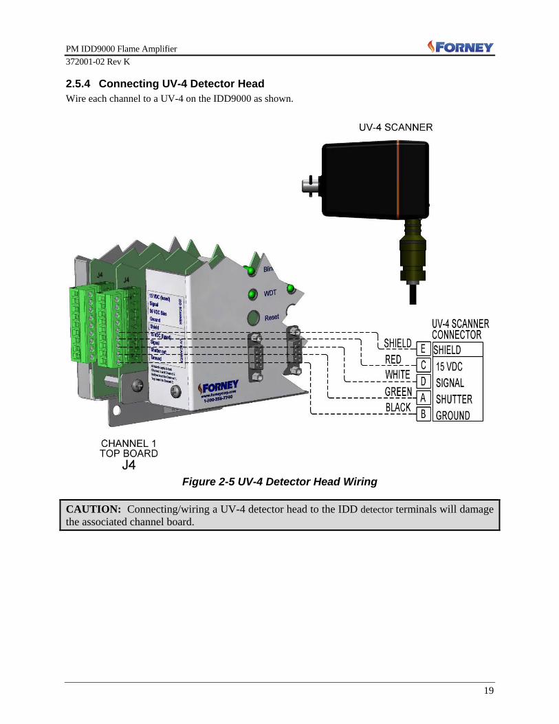
2.5.4 Connecting UV-4 Detector Head Wire each channel to a UV-4 on the IDD9000 as shown.
Figure 2-5 UV-4 Detector Head Wiring
CAUTION: Connecting/wiring a UV-4 detector head to the IDD detector terminals will damage the associated channel board.

PM IDD9000 Flame Amplifier 372001-02 Rev K
20
2.5.5 Connecting an IDD and a UV-4 Either channel of the IDD9000 can be wired for an IDD or UV-4 detector head. Wire according to the following diagram. Note: Each channel can only operate one detector at a time and should be wired to EITHER an IDD detector OR a UV-4 detector, not both on the same channel.
Figure 2-6 IDD and UV-4 Detector Head Wiring
PM IDD9000 Flame Amplifier 372001-02 Rev K
21
2.7 Hardware Control Inputs
2.7.1 Blind Input – J8 For compatibility with installed wiring when retrofitting legacy Forney flame amplifiers, two blind control inputs are provided, an AC power activated blind input and a ground activated input. Either of these inputs can be used to activate the amplifier's blind function. The ground actuated blind input is provided with an internal pull-up resistor to hold it in the logic high (not blinded) condition, so it is only necessary to apply a ground connection to activate it. When the amplifier is blinded, the flame failure response time (FFRT) timer is not disabled and signal level comparisons to pick-up and dropout points continues, so loss of flame indication will occur following the FFRT delay. Blind Verification Test
1. Disable the BLIND function, if used. Use an artificial light source (an incandescent lamp for infrared or a UV light source for UV), and verify that the appropriate FLAME LED lights.
2. Activate the BLIND function for the flame detector head(s) being used. Verify that the FLAME LED goes out.
CAUTION: The amplifier blind function does not close the flame detector shutters or switch off the photocell bias. Therefore, the blind function cannot be used to verify noisy flame detectors that are failing self-check. All flame detectors, noisy or not, will read zero signal when the amplifier blind function is used.
2.7.2 Sense B Input – J8 The AC powered Sensitivity B, "Sense B", operated input is provided for compatibility with installed wiring when retrofitting legacy Forney flame amplifiers. Powering the Sense B input is equivalent to grounding the “Profile Select 0” (PS0) input. The amplifier will operate with Profile number 0 if the Sense B input is not powered and Profile 1 when the Sense B input is powered. Additional wiring will need to be connected to the PS1 and PS2 inputs if access to the remaining six operating profiles is desired. Activating Sense B will increase the Active Profile Number selected by one (1). Example: Active Profile 2 will advance to 3; Active Profile 4 will advance to 5, etc.
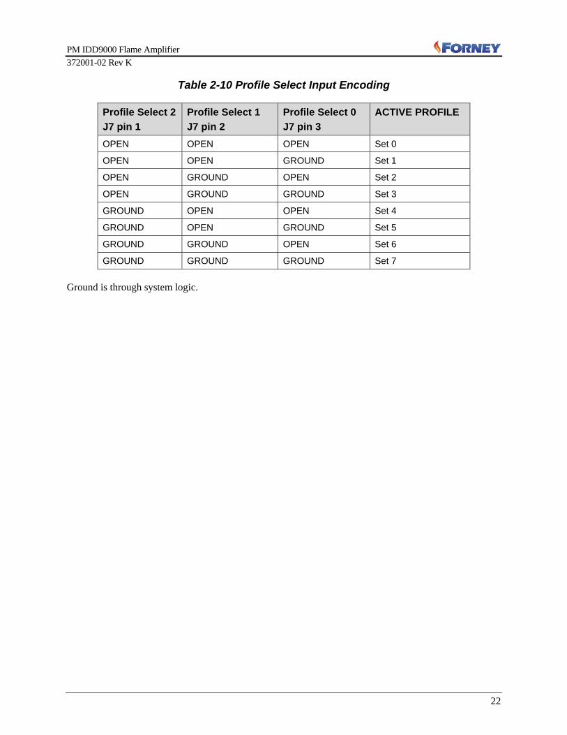
2.7.3 Operating Profile Select Inputs – J7 The IDD9000 Flame Amplifier has non-volatile memory storage for eight sets of operating profiles, numbered from 0 to 7. The stored profiles are intended to allow for easy switching between commonly used burner operating conditions without requiring manual re-tuning of the flame amplifier. The active profile is selected by three 5-Volt logic level inputs, PS2, PS1, and PS0. These inputs are encoded in reverse binary. Each profile contains a full set of operating parameters see Table 2-11 Operating Profiles. The amplifier constantly reads the profile selected by the Profile Select input code and displays the Active Profile number in the lower right corner of the Termiflex / SmartDisplay®. The Active Profile can be changed at any time other than while in the tuning loop by repositioning the Profile Select inputs. Any tuning parameter changes can be saved only to the Active Profile. Example: Active Profile 0 is displayed as “Set 0”. Note: It is only necessary to connect the hardwired inputs to the amplifier ground to select the desired profile.
PM IDD9000 Flame Amplifier 372001-02 Rev K
22
Table 2-10 Profile Select Input Encoding
Profile Select 2 J7 pin 1
Profile Select 1 J7 pin 2
Profile Select 0 J7 pin 3
ACTIVE PROFILE
OPEN OPEN OPEN Set 0
OPEN OPEN GROUND Set 1
OPEN GROUND OPEN Set 2
OPEN GROUND GROUND Set 3
GROUND OPEN OPEN Set 4
GROUND OPEN GROUND Set 5
GROUND GROUND OPEN Set 6
GROUND GROUND GROUND Set 7 Ground is through system logic.

PM IDD9000 Flame Amplifier 372001-02 Rev K
23
2.8 Operating Modes Note: MODE 1: IDD PPS is for operating a single IDD series (flame flicker) type detector only. MODE 2: UV-4 PPS is for operating a single output pulse detector only. All operating profiles are initialized via a profile flag and with the default settings shown.
Table 2-11 Operating Profiles Termiflex Display Mode 1: IDD PPS only Mode 2: UV-4 PPS
only IDD GAIN 0 -
SPECTRAL RANGES 1 -
CORNER 1 80 Hz -
CORNER 2 200 Hz -
WEIGHT 1 1 -
CORNER 3 1024 Hz -
CORNER 4 1024 Hz -
WEIGHT 2 1 -
IDD PICKUP- PPS 500 -
IDD DROPOUT- PPS 100 -
IDD ANALOG LOW- PPS 0 -
IDD ANALOG HIGH- PPS 3000 -
UV-4 MULTIPLIER - 1
UV-4 PICKUP- PPS - 500
UV-4 DROPOUT- PPS - 100
UV-4 ANALOG LOW- PPS - 0
UV-4 ANALOG HIGH- PPS - 3000
FFRT 3.8 Seconds
CHECK DELAY 120 Seconds

PM IDD9000 Flame Amplifier 372001-02 Rev K
24
2.9 Configuring the Termiflex/SmartDisplay® Terminal with 25 Pin Connector
The PM IDD9000 uses the same detachable Termiflex / SmartDisplay® unit for programming the amplifier as the previous Forney flame amplifiers, however the Termiflex / SmartDisplay® terminal with 25-pin must be reconfigured. NOTE: If the Termiflex / SmartDisplay® unit has a 9-pin connector, then the factory defaults are already set as required. Do NOT reconfigure. 1. Attach the 25 to 9- pin adapter to the Termiflex / SmartDisplay terminal. 2. To enter the Termiflex / SmartDisplay® configuration menu, press and hold the lower left blue ( )
and lower right red ( ) keys while the unit is executing its power-on-self-test. Hold both keys down until MAIN MENU display comes up.
a. Press F1 to enter COM Menu settings b. Press F2 (NXT) to scroll through settings until Baud Rate = 19.2K is displayed. c. Press F3 (CONT) to continue to Parity. Use F1 or F2 to scroll through settings until “even” is
displayed. d. Press F3 to continue to DATA, STOP BITS = 8, 1, e. Press F3 to continue to DISP SERIAL ERRORS ? Press F1 for YES f. Press F3 to continue to AUD SERIAL ERRORS ? Press F1 for YES g. Pressing F3 will take you back to the Main Menu. h. Press F2 for DSP - DISP CTL CHARS ? will be displayed. Use F1 and F2 to scroll
through the settings until “no” is displayed. i. Press F3 to continue to DISP ESC CHARS ? Use F1 and F2 to scroll through the settings
until “no” is displayed. j. Press F3 to continue to CURSOR VISIBLE ? Press F1 for “yes”.
Table 2-12 Termiflex/SmartDisplay® Configuration Settings for IDD 9000
Programming (Factory Default for Termiflex with 9-pin Adapter) COM: DSP: KBD:
Baud: 19.2K Disp Ctl Chars: No Local Echo: No
Parity: Even Disp Esc Chars: No Key Repeat: Slow
Data, Stop Bits: 8,1 Cursor Visible: Yes Audible Keys: Yes
DSP Serial Errs: Yes Auto Line Wrap: Yes Simplified KBD: No
Aud Serial Errs: Yes New Line on CR: No PGM Function Keys: No
Disp Self Test: Yes
Backlight Level: 0
Backlight On: No

PM IDD9000 Flame Amplifier 372001-02 Rev K
25
If you need to re-configure the Termiflex / SmartDisplay® for a PM-DR6101E reference the following table for appropriate settings.
Table 2-13: Termiflex / SmartDisplay® Configuration Settings for PM or RM DR6101E Programming (Factory Default for Termiflex with 25-pin adapter)
COM: DSP: KBD:
Baud: 4800 Disp Ctl Chars: No Local Echo: No
Parity: Even Disp Esc Chars: No Key Repeat: Slow
Data, Stop Bits: 7,1 Cursor Visible: Yes Audible Keys: No
DSP Serial Errs: No Auto Line Wrap: No Simplified KBD: No
Aud Serial Errs: No New Line on CR: No PGM Function Keys: No
Disp Self Test: Yes
Backlight Level: 5
Backlight On: No

PM IDD9000 Flame Amplifier 372001-02 Rev K
26
Section 3 Amplifier Tuning
The amplifier tuning mode can be reached using either the handheld Termiflex/SmartDisplay® or the Forney Terminal Emulator Software (TES) installed on a laptop computer. Table 3-1 Keypad Commands summarizes the keypad commands available in the IDD9000 Flame Amplifier firmware program.
Table 3-1 Keypad Commands Function Termiflex / SmartDisplay® Key
strokes Terminal Emulator Software
(TES) Button
Enter the tuning loop / 1 3 Slash one three Config
Do self-check now ? Question mark Self Test
The three key sequence “/13” (slash, one, three) is pressed to enter the tuning loop. The amplifier is tuned in the active mode only. Notes: • During tuning, any changes that cause loss of flame indication will be transmitted to the main flame
relay following the FFRT delay. • While tuning, if the main flame relay drops, the system will not re-initiate Flame-on status until the
user exits the tuning loop. If the flame lamp indicator is on when the tuning loop is exited, the system will then return to flame-on status.
• When one channel enters tuning mode, periodic self check is suspended on both channels. On exiting tuning mode, periodic self check operation resumes.
• The IDD9000 Flame Amplifier allows a maximum of 10 minutes of use while in the tuning loop before a time-out will occur. At a time-out, the tuning loop is exited and the system returns to active operation, any unsaved changes that were entered will be lost.
• Upon time-out, completion of tuning or unplugging the Termiflex, the IDD9000 returns to normal operating mode. This is indicated by the WDT LED starting to flash. Pressing the reset button ensures the IDD9000 has returned to normal operation.
3.1 Mode The first screen displayed in the tuning loop allows selection of the operating MODE. Each Channel of the amplifier can use a single IDD detector or a single output pulse detector (example UV-4). The numeric keys 1 or 2 are pressed to set that MODE. Press F4, “NXT” to continue. NOTE: Any flame detector connected to the unselected mode input will receive power but is not monitored for signal level or tested during self-check
3.1.1 IDD Channel Tuning If MODE 1 is selected, a sequence of IDD channel tuning screens will follow. If available, use the USB oscilloscope to facilitate IDD tuning. Any oscilloscope with an FFT function may be used, but Forney recommends using the Forney Tuning Kit which includes an oscilloscope with FFT. Reference Forney Publication 372001-10 for more details. While not required, an oscilloscope with FFT is more effective in determining the lower and upper corner frequencies; pick-up and dropout points; and analog output low and high points.

PM IDD9000 Flame Amplifier 372001-02 Rev K
27
3.1.1.1 IDD Gain To avoid saturation, the gain must be set to midrange or below. If the flame signal is clipped by excessive amplification, its spectrum is corrupted, making the flame on/off decision unreliable. Factory default is a gain value = “0”. Under most installations this should be sufficient gain for operation of the amplifier. The “weight factor” multiplier explained in the next section will also set output gain. If lack of gain is realized, then gain setting should be increased. Note: Gain setting should be as low as possible, typically 0, to ensure safety. As boiler load increases raw signal strength will increase. If this signal strength is too high, then gain will need to be reduced. Figure 3-2 & 3-3 will apply so as not to saturate the amplifier. “<<” need to be avoided as this a high signal strength near saturation. For best tuning and operation, adjust the gain up or down, so the most LEFT arrows are showing and no RIGHT arrows are visible. Use the F1, “DEC” and F2, “INC” keys on the Termiflex to make adjustments. The correct GAIN setting has the signal strength indicator “>” extending from the left side to the approximate center of the display while the burner is operating. The GAIN value is stored as a number from 0 to 7, where 7 corresponds to the maximum GAIN of 32x. Gain setting should be as low as possible, typically 0, to ensure safety.
Note: Because the IDD signal is monitored from the A/D converter output for the purpose of setting the GAIN, (ahead of the band-width filters and weights) any subsequent adjustments to the corner frequencies or weighting factors will not affect the GAIN setting. If the flame detector is adjusted or replaced, the GAIN setting will need to be rechecked.
3.1.1.2 IDD Frequency Ranges The Frequency Ranges allow the user to specify one or two discrete frequency ranges for inclusion into the IDD output signal level for pick-up and dropout comparisons. Each frequency range is defined by its lower and upper corner frequencies. Weight factors are also available to allow an imbalanced ratio of signal energy to be included from two ranges if desired. A single range is adequate to produce the low-pass, high-pass, or band-pass filter functions. Additionally, two frequency ranges can be used to do combinations of low-pass, high-pass, and band-pass filter functions. This feature is available to produce a notch filter function if a difficult application requires this option. The incoming detector head signal may be tuned in 1 or 2 ranges. The ranges cover from 12Hz to 1024HZ. The system defaults to 1 range. If 2 ranges are chosen, adjust them both, upper and lower ends, but NO overlapping of frequencies is allowed.
Press F1 - CHG then type “2” (to change from 1 range to 2 ranges) Press F4 – NXT
IDD Spectrum Ranges=2 CHG NXT
F1 F2 F3 F4
>>>>>>>>>>>> Gain=0 DEC INC NXT F1 F2 F3 F4
Figure 3-2 Correct Gain Setting
Figure 3-1 Incorrect Gain Setting >>>>>>>>>>>>««« Gain=1 DEC INC NXT F1 F2 F3 F4

PM IDD9000 Flame Amplifier 372001-02 Rev K
28
The next tuning screen displays the lower and upper corner frequencies and weighting factors defined for the range. Press F1, “CHG” to make changes. If two frequency ranges are selected, the display will show both frequency ranges’ corner frequencies and weighting factors. Press F1 - CHG1 or F2 - CHG2 to edit the corner frequencies or weighting factors for range 1 or range 2 respectively. The next screen will display the acceptable limits for the parameter to be changed and will not accept any values out-of-range (12-1024 Hz). The corner frequencies entered must be numbers evenly divisible by 4 or the system will reduce the value entered to the next smaller value that is evenly divisible by 4. For example, if the user enters 50Hz, the value will be automatically changed to 48Hz when it is accepted. Set the lower end first then the upper end. The Weight Factor is represented by WF on the Termiflex/ SmartDisplay screen. This is the multiplier for each range. When it is felt insufficient counts exist, use this Weight Factor to improve dynamic range of PPS Counts. Weight factors are limited to integers between 1 and 5 and are permitted to be the same for each range if desired. Larger weight factors can be used as a “downstream gain” setting to increase the IDD signal value. If a narrow bandwidth is being used, the user must be careful to stay below the maximum signal value of 8190. Press F1 - CHG F1 - LO - type in lower corner frequency i.e. “100” F4 - OK F2 - HI - type in higher corner frequency i.e. “140” F4 - OK F3 - WF - type in “2” F4 - OK F4 - OK F4 - NXT The second range, if used, must be located at higher frequencies than the first. No overlap between the two ranges is allowed. Therefore, the upper corner of the lower range cannot be specified to a frequency higher than the low corner of the upper range. Corners and WF for Range 2 are changed the same as Range 1.
Range 2 < 956> 100 - 140 x2 LO HI WF OK
F1 F2 F3 F4
Range 1 < 956> 100 - 140 x2 LO HI WF OK
F1 F2 F3 F4
Freq Range(s): 80 - 200 x1 CHG NXT
F1 F2 F3 F4
Freq Range(s): 80 - 200 x1 1024 - 1024 x1 CHG1 CHG2 NXT
F1 F2 F3 F4

PM IDD9000 Flame Amplifier 372001-02 Rev K
29
IDD SIGNAL: 956 PU: 800 HI: 1100 DO: 500 LO: 560 PU DO NXT F1 F2 F3 F4
3.1.1.3 IDD Pick-Up and Dropout Points This screen displays:
• Average IDD signal level in pulses per second (PPS) using the configuration settings entered thus far (IDD SIGNAL),
• Programmed pick-up (PU), • Dropout points (DO), • Highest and lowest signal values seen since accessing
this screen (HI and LO).
Note: Linger for several minutes on the IDD SIGNAL screen to gather some trend data. Remember, the SmartDisplay /Termiflex times out after 10 minutes of activity. Notice how the high (HI) and low (LO) value range keeps expanding. Pick-up and dropout points are limited to absolute minimum and maximum of 0 to 8190. The pick-up point should be less than the average signal value (i.e. IDD SIGNAL: 956) and greater than the minimum signal value (i.e. LO: 560). The dropout value should be less than the minimum signal value (i.e. LO: 560). The pick-up point must be greater than the dropout point. Press F1 - PU to change the pick-up value. i.e. 800 was selected for PU (560 < 800 > 956) Press F2 - DO to change the dropout point. i.e. 500 (500<560).
3.1.1.4 IDD Analog Output Low and High Points The analog output value corresponds to the average of the last five instantaneous counts of signal intensity. The IDD ANALOG OUTS screen shows the programmed values for the IDD analog output low and high points. Plus, it displays the pick-up and dropout points that were just programmed in the last section for reference. The Analog Output HI and LO will set the 0-10V and 4-20mA outputs and can be set to yield the most information to almost nothing more than ON/OFF. To convey the most information, set the HI to the actual high displayed on the IDD Signal screen and the low to a value lower than the dropout (DO) value, which would be 1100 & 300. To change the programmed values for IDD Analog Outputs on the Termiflex/SmartDisplay: Press F1 - HI – type in “1100” F4 - OK F2 - LO - type in “300” F4 - OK F4 – NXT
IDD SIGNAL: 956 PU: 450 HI: 980 DO: 300 LO: 770 PU DO NXT F1 F2 F3 F4
IDD ANALOG OUTS HI:1000 PU: 800 LO: 0 DO: 500 HI LO NXT F1 F2 F3 F4
IDD ANALOG OUTS HI:1100 PU: 800 LO: 300 DO: 500 HI LO NXT F1 F2 F3 F4

PM IDD9000 Flame Amplifier 372001-02 Rev K
30
Note: The 4-20 output is not to be considered a calibrated output, to this end the output scale from the factory is set at a default value of 3000 well beyond the usable range. In order to acquire a reasonably linear output for display purposes, after the amplifier is properly set up and tested for proper flame discrimination adjust these ranges as described above.
3.1.2 UV-4 Channel Tuning If operating Mode 2 is selected, the following screens will appear. Screen Values on Screen To Make Changes Notes
UV-4 Count Multiplier Programmed Drop Out (DO) and Pick Up (PU) PPS value of the incoming signal Multiplier value
Press F1, "DEC" or F2, "INC" to change the Multiplier Press F4, "NXT" will accept the value.
Multiplier value goes from 1 to 5. It is a straight multiplier to the PPS, to boost a low count. For best tuning and operation, adjust the multiplier so the PPS Count average is at least 500.
UV-4 Channel Pick-Up and Dropout Points
Active PPS signal level in Hz as an average Programmed pick-up points Dropout points Highest and lowest actual signal values seen
Press F1, “PU” or F2, “DO” Press F4, "NXT" will accept the value.
Pick-up and dropout points are limited to absolute minimum and maximum of 0 to 8190. The pick-up (PU) point should be less than the average signal value (i.e. PPS SIGNAL: 860). The dropout value should be less than the minimum signal. The pick-up point must be greater than the dropout point.
UV-4 Analog Output Low and High Points
Programmed values for the PPS analog output low and high points. Programmed pick-up and dropout points being used
Press F1, "HI" or F2, "LO" Press F4, "NXT" will accept the value.
The Analog Output HI and LO will set the 0-10V and 4-20mA outputs and can be set to yield the most information to almost nothing more than ON/OFF. To convey the most information, set the HI to the actual high displayed on the PPS Signal screen and the low to a value lower than the dropout (DO) value.
DO PU PPS 100 500 460 Multiplier = 1 DEC INC NXT F1 F2 F3 F4
PPS SIGNAL: 860 PU: 500 HI: 880 DO: 100 LO: 840 PU DO NXT F1 F2 F3 F4
PPS ANALOG OUTS HI: 1000 PU: 700 LO: 0 DO: 200 HI LO NXT F1 F2 F3 F4
NOTE: Linger for several minutes on this screen to gather some trend data. Remember, the SmartDisplay/Termiflex times out after 10 minutes. Notice how the high (HI) and low (LO) value range keeps expanding.
CAUTION: The analog outputs are not intended for control of safety critical processes.
PM IDD9000 Flame Amplifier 372001-02 Rev K
31
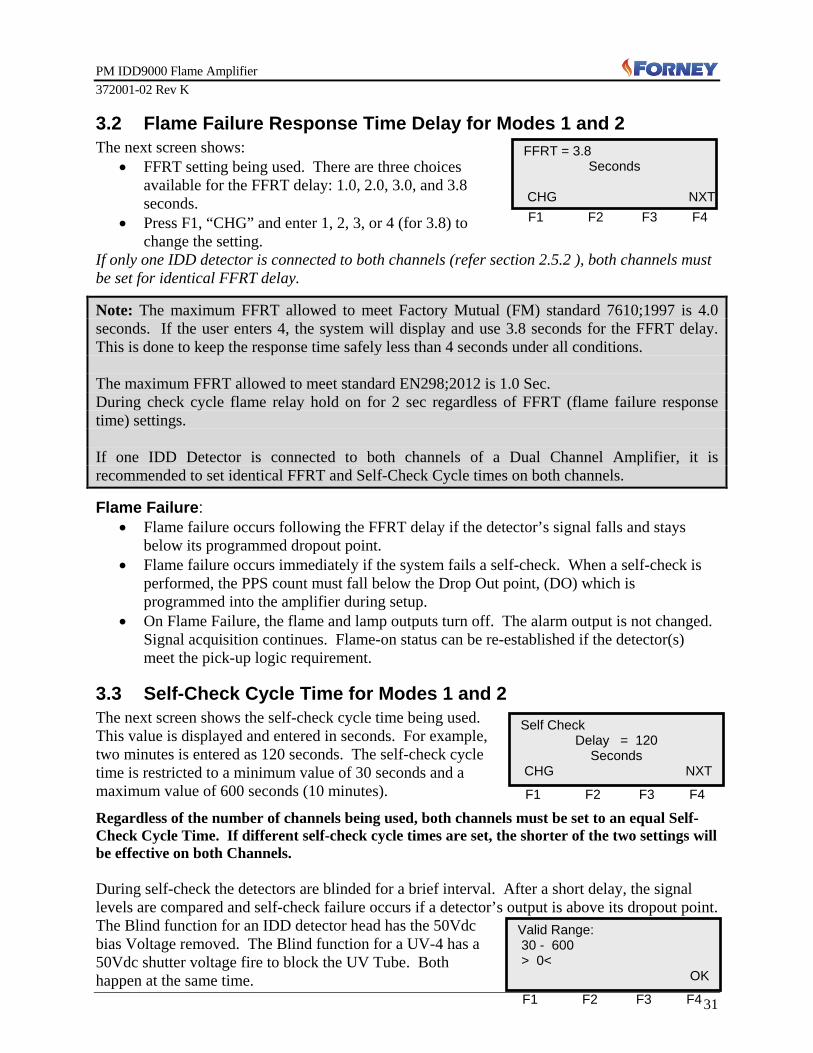
3.2 Flame Failure Response Time Delay for Modes 1 and 2 The next screen shows:
• FFRT setting being used. There are three choices available for the FFRT delay: 1.0, 2.0, 3.0, and 3.8 seconds.
• Press F1, “CHG” and enter 1, 2, 3, or 4 (for 3.8) to change the setting.
If only one IDD detector is connected to both channels (refer section 2.5.2 ), both channels must be set for identical FFRT delay.
Note: The maximum FFRT allowed to meet Factory Mutual (FM) standard 7610;1997 is 4.0 seconds. If the user enters 4, the system will display and use 3.8 seconds for the FFRT delay. This is done to keep the response time safely less than 4 seconds under all conditions. The maximum FFRT allowed to meet standard EN298;2012 is 1.0 Sec. During check cycle flame relay hold on for 2 sec regardless of FFRT (flame failure response time) settings. If one IDD Detector is connected to both channels of a Dual Channel Amplifier, it is recommended to set identical FFRT and Self-Check Cycle times on both channels.
Flame Failure: • Flame failure occurs following the FFRT delay if the detector’s signal falls and stays
below its programmed dropout point. • Flame failure occurs immediately if the system fails a self-check. When a self-check is
performed, the PPS count must fall below the Drop Out point, (DO) which is programmed into the amplifier during setup.
• On Flame Failure, the flame and lamp outputs turn off. The alarm output is not changed. Signal acquisition continues. Flame-on status can be re-established if the detector(s) meet the pick-up logic requirement.
3.3 Self-Check Cycle Time for Modes 1 and 2 The next screen shows the self-check cycle time being used. This value is displayed and entered in seconds. For example, two minutes is entered as 120 seconds. The self-check cycle time is restricted to a minimum value of 30 seconds and a maximum value of 600 seconds (10 minutes).
Regardless of the number of channels being used, both channels must be set to an equal Self-Check Cycle Time. If different self-check cycle times are set, the shorter of the two settings will be effective on both Channels. During self-check the detectors are blinded for a brief interval. After a short delay, the signal levels are compared and self-check failure occurs if a detector’s output is above its dropout point. The Blind function for an IDD detector head has the 50Vdc bias Voltage removed. The Blind function for a UV-4 has a 50Vdc shutter voltage fire to block the UV Tube. Both happen at the same time.
FFRT = 3.8 Seconds
CHG NXT F1 F2 F3 F4
Self Check Delay = 120
Seconds CHG NXT F1 F2 F3 F4
Valid Range: 30 - 600 > 0< OK F1 F2 F3 F4

PM IDD9000 Flame Amplifier 372001-02 Rev K
32
If one channel fails at any time, for any reason, the other channel will continue to operate.
Example set SELF CHECK Delay to 5 minutes. F1 - CHG – type in 300 F4 - OK F4 – NXT
Note: Timed self-check is inhibited if there is no flame indication or if the system is being tuned or blinded. System performs self-check 2 seconds after detection of flame. Any self-check failure will cause immediate flame failure. The Flame and Lamp LEDs will extinguish, and the Red Alarm LED will light. The display will show a repeating error message informing the user the flame detector failed.
3.4 Saving Configuration The RESTORE OR SAVE screen gives you 3 options.
• TEST your setup using F4 to do a SELF CHECK. • SAVE your setup using F2 to do a SAVE NEW. • DISCARD your setup using F1 to reload the
PREVIOUS SETTINGS. If the SELF CHECK fails, the unit does a lock out, to fail safe, as required. Press the RESET button on the front panel to restore the original settings, and start again. If SELF CHECK passes, select SAVE NEW and you may want to sweep thru the settings again for further tweaking.
• F2 - SAVE NEW
Caution: If the system is left in tuning mode without saving, it will time out after 10 minutes to the previously SAVED parameters. However, if the Termiflex is removed without saving the new configurations, it will revert to the previously SAVED parameters after 2 seconds.
Self Check Delay = 300
Seconds CHG NXT F1 F2 F3 F4
RESTORE OR SAVE 860 PPS UV LOAD SAVE SELF OLD NEW CHK F1 F2 F3 F4
PPS CHK FAIL PPS CHK FAIL PPS CHK FAIL
F1 F2 F3 F4
860 PPS UV Set 0 F1 F2 F3 F4

PM IDD9000 Flame Amplifier 372001-02 Rev K
33
3.5 Functions Unavailable While Tuning The following functions are not available when inside the tuning loop:
• The self-check cycle timer is not incremented while inside the tuning loop. The timer resumes counting and the amplifier self-checks when the tuning loop is exited.
• The profile select inputs are not checked while tuning. If the profile is changed while tuning, any changes made will be lost and the new profile loaded when the tuning loop is exited.
• The blind input is not checked while tuning. If this input is changed while tuning, the blind/un-blind will occur when the tuning loop is exited.
• The watchdog timer/code is active at all times, but the WDT LED stops toggling while in the tuning loop to serve as a visual reminder that tuning is still in progress.
3.6 Analog Outputs • The analog output value corresponds to the average of the last five instantaneous counts
of signal intensity. • The analog outputs (0-10V and 4-20mA) are linearly scaled between the programmed
low and high points respectively. These will output minimum (0V and 4mA) if the input channel is off or the signal level is at or below the programmed low point and will read full scale (10V and 20mA) if the signal level is at or above the programmed high point.
• No hardware zero or span adjustments are provided. • The 15 Volt outputs to the 4-20mA indicators are fused with 1/8-Ampere plug-in fuses
accessible by removing the amplifier cover. • The 0-10V outputs have a 1000-Ohm output resistance so these outputs can only be used
with a high input-resistance indicating or logging device. CAUTION: The analog outputs are not intended for control of safety critical processes.
3.7 Amplifier Shutdown/Failure If the amplifier fails or is shutdown the main flame and lamp outputs are turned off. The alarm output is turned on. Signal acquisition stops. An error message repeatedly displays. Power off/on or a Reset is required to restart the system.

PM IDD9000 Flame Amplifier 372001-02 Rev K
34
Section 4 Maintenance
This section contains maintenance instructions for the PM IDD9000. CAUTION: This amplifier contains "STATIC SENSITIVE" components. Use standard electrostatic-discharge (ESD) procedures whenever handling the board. WARNING: Ensure all Flame Detector amplifiers, detectors, and cables are installed properly, and the amplifier is programmed exactly as described in this manual. DEVIATION IN ANY CASE MAY RESULT IN CATASTROPHIC FAILURES AND SEVERE DAMAGE TO EQUIPMENT AND/OR INJURY TO PERSONNEL.
4.1 Tuning The flame detection system should be tuned at initial installation in accordance with Section 3 of this manual. Following initial installation, the tuning parameters should be rechecked at periodic intervals to maintain optimum system performance.
4.2 Troubleshooting If the flame detection system fails, isolate the fault to the flame detector head, the cable between the head or the amplifier. The following instructions provide general guideline for fault isolation. 1. Measure the power inputs at J1 of the PM IDD9000 PCB. Ensure that all voltage inputs
are at the correct level. (Refer to Table 2-2.)
2. If the PCB fails to respond correctly, the system program may be stalled. Press the Reset pushbutton switch to clear the CPU, and restart the program.
3. The PCB contains five clip-mounted fuses on the board. If restarting the program does
not resolve the problem, remove power from the system and check for open fuses. Replace open fuses as required. (Refer to Table 6-1 for a list of fuses mounted on the PCB.) If any other component requires replacement, return the PCB to Forney for repair.
4. Use documentation supplied with the flame detector head to isolate a fault to the head or
cable.
4.3 Storage and Handling Requirements Store the PM IDD9000 amplifier in its shipping box until used. See the specifications section of this manual for storage temperature and humidity ranges. Normal static precautions should be taken in handling parts sensitive to electrostatic discharge (ESD).

PM IDD9000 Flame Amplifier 372001-02 Rev K
35
Section 5 RMA / Warranty Forney Corporation warrants this product to be free of defective material and workmanship. Forney will replace this equipment as long as it is being used for its intended use and is found to be defective upon receipt up to the expiration of the warranty period. Prior to returning any material to Forney, please contact your Forney customer service representative and provide the contract number or the customer purchase order number.
Section 6 Spare Parts When ordering spare parts, contact Forney’s Aftermarket Department via any one of the following methods and furnish the following information. E-mail Phone Fax [email protected] 972-458-6100 or
972-458-6142 or 1-800-356-7740 (24-hour direct line)
972-458-6600
1. Contract number 2. Customer purchase order number 3. For each part ordered, provide the following information:
a. Part number b. Part description c. Quantity required
6.1 Recommended Spare Parts The recommended spare parts list in the table below advises of replacement parts that should be in the customer’s stock.
Table 6-1 Replacement Parts
Fuse Value Function Part No.
F1 4.0A Main AC Power 9235702
F2 .125A IDD Detector Power 9235704
F3 .250A UV-4 Detector Power 9235703
F4 .125A UV-4 4-20mA Output 9235704
F5 .125A IDD 4-20mA Output 9235704
F6 62mA IDD Bias 2820-55
Insulating Pipe Nipple, Fiberglass 75168-01
Kit for IDD-Ultra Retrofit – Grounding 370279-01 NOTE: Drawing number, stock number, and part number are interchangeable for Forney supplied items.

PM IDD9000 Flame Amplifier 372001-02 Rev K
36
Commissioning Checklist
Forney Contract No:
Site:
Burner/Igniter No. Tuning Parameter Settings Profile #____ Profile #____ Profile #____ Profile #____
MODE 1 Sense A
Sense B
Sense A
Sense B
Sense A
Sense B
Sense A
Sense B
IDD GAIN
FREQ RANGES
CORNER 1
CORNER 2
CORNER 3
CORNER 4
WEIGHT 1
WEIGHT 2
IDD PICKUP- PPS
IDD DROPOUT- PPS
IDD ANALOG LOW- PPS
IDD ANALOG HIGH- PPS
MODE 2
UV-4 MULTIPLIER
UV-4 PICKUP- PPS
UV-4 DROPOUT- PPS
UV-4 ANALOG LOW- PPS
UV-4 ANALOG HIGH- PPS
MODES 1 & 2
FFRT
CHECK DELAY If using more than four profiles, copy this sheet to document settings for all profiles.