Embed Size (px)
Citation preview

Jay R.SmithMfg.Co.®
Grease + Gard®GREASE REMOVAL SYSTEM
=
OPERATION&MAINTENANCEMANUAL
8165GG 8175GG

Grease+Gard® Installation &Operation InstructionsGrease+Gard® is designed to remove the grease from the interceptor keeping the interceptor free of grease.
However, Grease+Gard® is not a solids Interceptor. A solids interceptor is required prior to the Grease+Gard®
unit in order for it to function properly. Please reference Solids Interceptor, at www.jrsmith.com.
Installation1) Install Grease+Gard® in accordance to local, state or national plumbing codes, which ever applies to
your jurisdiction. If no codes apply in your area, please reference our installation guide. It is essen-tial the discharge is vented properly to prevent any siphon problems. Improper venting causingsiphon problems will void the warranty.
2) If this is a retrofit installation, jet (power clean) the lines prior to installation.3) Remove the GRD portion of the Grease+Gard® from the interceptor for installation. Install flow con-
trol, inlet and outlet piping.4) After installing the interceptor portion, fill the unit completely with water. Check for leaks.5) Once the unit is filled with water you are now able to install the GRD tower portion of the
Grease+Gard® unit. Latch the GRD tower down to the cover flange.6) Plug the Grease+Gard® unit into a GFI (ground fault circuit breaker) supplied by others.7) Adjust timer to your required needs. Reference timer diagram for adjustments and settings. To ini-
tially start, it is recommended setting the timer for 45 minutes after each meal. If breakfast, lunch &dinner are served, set the timer to come on from 10:00AM to 10:45AM, then 2:30PM to 3:15PM forlunch, then 9:30 PM to 10:15 PM for dinner. Do not exceed one hour running time.
Check the interceptor for grease over the next week to insure you are removing all the grease daily. Ifgrease is not being removed add some additional time to the clock. It is recommended for the clock tobe set for approximately 4:00AM to 4:45AM and time as needed to keep the interceptor clean.
For 24 hour high volume restaurants it is recommended to start by setting the timer 15 minutes per eachhour of the 24 hour time clock.
Weekly / Daily Maintenance1) Daily, remove grease container and empty daily or more if needed. Dispose of grease in a proper
location / rendering barrel. Do not dump back into the plumbing or drainage system. Check withlocal jurisdiction for proper disposal requirements.
1

2) Daily, when removing the grease container and after emptying, remove the grease trough & skimmerblade assembly to be cleaned.
3) Weekly, Unplug the Grease+Gard® and remove the GRD tower and inspect the interceptor. Thereshould be no grease to very little grease in the interceptor. If there is 1/4" or more of grease, the timeclock should have 45 minutes added to the cleaning cycles.
4) Weekly, when inspecting the interceptor check top for grease and bottom for solids and sludge. TheGrease+Gard® interceptor is to be cleaned when at 25% capacity. This is where most jurisdictionswill want to see the unit evacuated and fully cleaned then refill with water, once full with water in-stall the GRD tower portion, set time clock and plug in the Grease+Gard®.
BMP’s (Best Management Practices)To get the best performance out of your Grease+Gard® unit we recommend using good BMP’s.
The more you reference back to BMP’s the less you will have to clean the Grease+Gard®.
1) Have a garbage can at the pre-rinse sink. Dry scrap all pots and dishes prior to rinsing. The majorityof the grease is at the pre-rinse sink. The fats, oils and grease are attached to the food particles. Themore scraps you put into the garbage will reduce your maintenance with your solids interceptors andyour Grease+Gard® system.
2) Make sure your pre-rinse sink is 120˚F or hotter at the rinse station (use gloves if needed).
TroubleshootingGrease+Gard® unit is backed up:This could be caused by several different issues. There may be too many solids in the interceptorcausing a back up. There may also be a clogged pipe. It is recommended jetting the lines prior toinstalling the system. Also check the plumbing vents to make sure they are clear.
Make sure the flow control is installed properly with nothing blocking/restricting the flow on the inletside of the flow control. Reference back to installation guide.
No Grease in the Container:Check power first. The GFI breakers trip really easy. Reset breaker if needed.Check timer clock for the on settings. Reference back to the time setting diagram.Check to make sure the grease trough with skimmer blades are in place.Check belt and skimmer blades for wear. Replace if needed.Skimmer blades should be touching both sides of the belt. If not the skimmer blades need to be replaced.
Foul Odors coming from the unit:Make sure the grease is being skimmed properly.If odors occur it is caused by either excessive grease or excessive solids in the unit.Unplug the unit and remove the Grease+Gard® tower. Remove the lid and clean the interceptor portionof the Grease+Gard® by evacuating everything out of the interceptor.Fill it back up with water, replace lid and tower, reset the time clock and plug back in to GFI circuit.
2

Assembly
1) Insert the grease trough to the upper stripper assembly.
2) Install the grease container.
3) Reference your installation instructions for plumbing, electrical and timerrequirements.
4) Screw the base flange to the interceptor cover.
5) Install unit and secure latches.
FIG. 8165 CUSTOMERASSEMBLYAFTER SHIPMENT
3

Assembly
1) Insert the grease trough to the upper stripper assembly.
2) Install the grease container.
3) Reference you installation instructions for plumbing, electrical and timerrequirements.
4) Screw the base flange to the interceptor cover.
5) Install unit and secure latches.
FIG. 8175 CUSTOMERASSEMBLYAFTER SHIPMENT
4

Remove Grease Trap Lid. Use the GREASE+GARD® base flangeas a template. Inspect grease trap prior to cutting and drillingholes. Make sure there is proper clearance for theGREASE+GARD® grease belt to protrude into the grease trap.
5

Cut top by using a saw. If it is a plastic top we recommend arotozip saw. It is a metal top we recommend drilling four holes.Holes to cut by using a hole saw large enough to fit your sawzallblade through. We recommend each hole to be drilled in approxi-mately the center of each line. Cut to each corner. After cuttingout the material clean up sharp edges with a grinder or a file.
6

We recommend marking 2 of the 8 holes. Drill the two holes witha 3/8" bit. Insert the mounting bolts, nuts and washers and snugthem down. Now drill the remaining 6 holes by using the base as atemplate. Install the remaining 6 bolts, nuts and washers. Tightenthem down evenly. Do not over tighten.
7

Now install grease trap lid with base attached to the lid.
8

Install Grease+Gard® tower to the base flange. Connect latches.Plug in the Grease+Gard® unit to the wall. Make sure the plug isgoing to a GFI breaker. If not have a electrician change thebreaker to a GFI breaker.
9
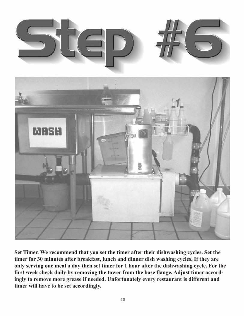
Set Timer. We recommend that you set the timer after their dishwashing cycles. Set thetimer for 30 minutes after breakfast, lunch and dinner dish washing cycles. If they areonly serving one meal a day then set timer for 1 hour after the dishwashing cycle. For thefirst week check daily by removing the tower from the base flange. Adjust timer accord-ingly to remove more grease if needed. Unfortunately every restaurant is different andtimer will have to be set accordingly.
10

FIGURE NUMBER 8165GG/8175GG, 8166GGL/8176GGL
PROGRAMMING OF THE GREASE+GARD® TIMER
VISIBLE PART OF THEORANGE DISC SECTIONSHOWS SWITCH-ON(GREASE REMOVAL) PERIOD.EACH DISC SECTION INDICATESMOTOR ON TIME OF 15MINUTES. DO NOT EXCEED ONEHOUR ON THE TIME CLOCK AT ATIME.
AT START UP ALLOW GREASEAROUND HEATER TO LIQUIFY IFNEEDED. SET FOR 45 MINUTESOF OPERATION AFTER EACHMEAL. INSPECT THE INTERCEP-TOR DAILY OVER THE NEXTWEEK TO MAKE SURE THEENOUGH TIME SET. IF IT IS RUN-NING TOO MUCH YOU WILLHAVE A LOT OF WATER IN THEGREASE THEN BACK OFF THECLOCK 15 MINUTES PER MEAL.
ROTATE TIMER DISC CLOCK-WISE AS SHOWN BY THEARROWS AND ALIGN WHITECENTER ARROW TO TIME OFDAY.
11
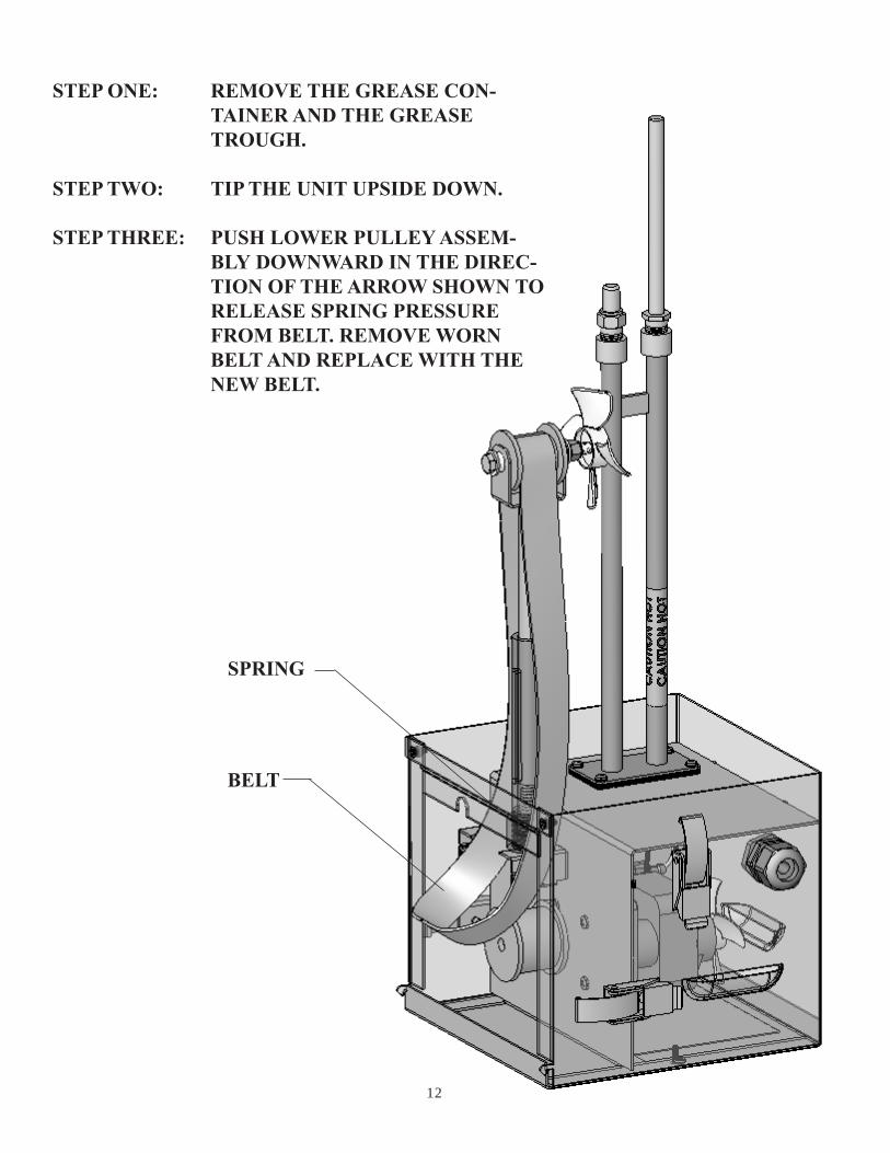
STEP ONE: REMOVE THE GREASE CON-TAINER AND THE GREASETROUGH.
STEP TWO: TIP THE UNIT UPSIDE DOWN.
STEP THREE: PUSH LOWER PULLEY ASSEM-BLY DOWNWARD IN THE DIREC-TION OF THE ARROW SHOWN TORELEASE SPRING PRESSUREFROM BELT. REMOVE WORNBELT AND REPLACE WITH THENEW BELT.
SPRING
BELT
12

GROUND TO HEATERMOUNT SCREW INSIDESS BODY COMPARTMENT
WHITEWIRES
HEATER THERMOSTATTIMER MOTOR TIMER CONTACT
BLACKWIRES
120VAC4 AMP
PLUG
1
M
M
2 3 4 5
13PM 2136B
07/2011